US10765312B2 - Shape discrimination vision assessment and tracking system - Google Patents
Shape discrimination vision assessment and tracking systemDownload PDFInfo
- Publication number
- US10765312B2 US10765312B2US15/403,656US201715403656AUS10765312B2US 10765312 B2US10765312 B2US 10765312B2US 201715403656 AUS201715403656 AUS 201715403656AUS 10765312 B2US10765312 B2US 10765312B2
- Authority
- US
- United States
- Prior art keywords
- user
- shapes
- recited
- vision
- results
- Prior art date
- Legal status (The legal status is an assumption and is not a legal conclusion. Google has not performed a legal analysis and makes no representation as to the accuracy of the status listed.)
- Active
Links
- 230000004438eyesightEffects0.000titleclaimsabstractdescription182
- 238000012360testing methodMethods0.000claimsabstractdescription322
- 238000000034methodMethods0.000claimsdescription56
- 125000001475halogen functional groupChemical group0.000claimsdescription16
- 230000036541healthEffects0.000claimsdescription15
- 229940079593drugDrugs0.000claimsdescription14
- 239000003814drugSubstances0.000claimsdescription14
- 230000004044responseEffects0.000claimsdescription14
- 230000033001locomotionEffects0.000claimsdescription11
- 210000001747pupilAnatomy0.000claimsdescription10
- 230000008859changeEffects0.000claimsdescription9
- 238000002483medicationMethods0.000claimsdescription8
- 230000003247decreasing effectEffects0.000claimsdescription7
- 230000002829reductive effectEffects0.000claimsdescription7
- 230000036772blood pressureEffects0.000claimsdescription4
- 230000000694effectsEffects0.000claimsdescription4
- 210000004279orbitAnatomy0.000claimsdescription4
- 206010015995Eyelid ptosisDiseases0.000claimsdescription3
- 210000000720eyelashAnatomy0.000claimsdescription3
- 201000003004ptosisDiseases0.000claimsdescription3
- 230000010344pupil dilationEffects0.000claimsdescription3
- 238000011282treatmentMethods0.000abstractdescription11
- 230000006870functionEffects0.000description32
- 230000009286beneficial effectEffects0.000description18
- 230000008901benefitEffects0.000description10
- 238000012544monitoring processMethods0.000description10
- 238000005259measurementMethods0.000description8
- 238000004458analytical methodMethods0.000description7
- 208000037265diseases, disorders, signs and symptomsDiseases0.000description7
- 230000004313glareEffects0.000description6
- 238000013459approachMethods0.000description5
- 208000035475disorderDiseases0.000description5
- 206010012689Diabetic retinopathyDiseases0.000description4
- WQZGKKKJIJFFOK-GASJEMHNSA-NGlucoseNatural productsOC[C@H]1OC(O)[C@H](O)[C@@H](O)[C@@H]1OWQZGKKKJIJFFOK-GASJEMHNSA-N0.000description4
- 239000003086colorantSubstances0.000description4
- 238000005516engineering processMethods0.000description4
- 238000011156evaluationMethods0.000description4
- 239000008103glucoseSubstances0.000description4
- 239000008280bloodSubstances0.000description3
- 210000004369bloodAnatomy0.000description3
- 230000001010compromised effectEffects0.000description3
- 238000010276constructionMethods0.000description3
- 230000001788irregularEffects0.000description3
- 208000002780macular degenerationDiseases0.000description3
- 238000003825pressingMethods0.000description3
- 238000012545processingMethods0.000description3
- 238000012216screeningMethods0.000description3
- 208000029257vision diseaseDiseases0.000description3
- 230000000007visual effectEffects0.000description3
- 201000004569BlindnessDiseases0.000description2
- 238000004891communicationMethods0.000description2
- 238000011109contaminationMethods0.000description2
- 238000012937correctionMethods0.000description2
- 238000013461designMethods0.000description2
- 201000010099diseaseDiseases0.000description2
- 208000030533eye diseaseDiseases0.000description2
- 238000004519manufacturing processMethods0.000description2
- 210000001525retinaAnatomy0.000description2
- 230000003068static effectEffects0.000description2
- 206010012667Diabetic glaucomaDiseases0.000description1
- LFQSCWFLJHTTHZ-UHFFFAOYSA-NEthanolChemical compoundCCOLFQSCWFLJHTTHZ-UHFFFAOYSA-N0.000description1
- 208000017442Retinal diseaseDiseases0.000description1
- 230000002159abnormal effectEffects0.000description1
- 230000004308accommodationEffects0.000description1
- 230000004913activationEffects0.000description1
- 230000001154acute effectEffects0.000description1
- 238000007792additionMethods0.000description1
- 206010064930age-related macular degenerationDiseases0.000description1
- 230000004075alterationEffects0.000description1
- 230000006399behaviorEffects0.000description1
- 230000005540biological transmissionEffects0.000description1
- 239000011111cardboardSubstances0.000description1
- 230000001413cellular effectEffects0.000description1
- 239000011248coating agentSubstances0.000description1
- 238000000576coating methodMethods0.000description1
- 238000004590computer programMethods0.000description1
- 239000012141concentrateSubstances0.000description1
- 238000013480data collectionMethods0.000description1
- 230000007547defectEffects0.000description1
- 230000007812deficiencyEffects0.000description1
- 238000012217deletionMethods0.000description1
- 230000037430deletionEffects0.000description1
- 239000000428dustSubstances0.000description1
- 210000000887faceAnatomy0.000description1
- 230000001815facial effectEffects0.000description1
- 239000000835fiberSubstances0.000description1
- 210000004209hairAnatomy0.000description1
- 235000004280healthy dietNutrition0.000description1
- 230000001771impaired effectEffects0.000description1
- 230000000670limiting effectEffects0.000description1
- 238000012886linear functionMethods0.000description1
- 239000000463materialSubstances0.000description1
- 238000007620mathematical functionMethods0.000description1
- 230000007246mechanismEffects0.000description1
- 238000010339medical testMethods0.000description1
- 239000002184metalSubstances0.000description1
- 229910052751metalInorganic materials0.000description1
- 150000002739metalsChemical class0.000description1
- 238000012986modificationMethods0.000description1
- 230000004048modificationEffects0.000description1
- 230000036651moodEffects0.000description1
- 230000006855networkingEffects0.000description1
- 239000000123paperSubstances0.000description1
- 239000011087paperboardSubstances0.000description1
- 230000036961partial effectEffects0.000description1
- 230000008447perceptionEffects0.000description1
- 239000004033plasticSubstances0.000description1
- 229920003023plasticPolymers0.000description1
- 230000002250progressing effectEffects0.000description1
- 238000012372quality testingMethods0.000description1
- 230000000284resting effectEffects0.000description1
- 238000012552reviewMethods0.000description1
- 230000035945sensitivityEffects0.000description1
- 230000011664signalingEffects0.000description1
- 238000006467substitution reactionMethods0.000description1
- 230000001360synchronised effectEffects0.000description1
- 230000004393visual impairmentEffects0.000description1
- 229940088594vitaminDrugs0.000description1
- 229930003231vitaminNatural products0.000description1
- 235000013343vitaminNutrition0.000description1
- 239000011782vitaminSubstances0.000description1
Images


Classifications
- A—HUMAN NECESSITIES
- A61—MEDICAL OR VETERINARY SCIENCE; HYGIENE
- A61B—DIAGNOSIS; SURGERY; IDENTIFICATION
- A61B3/00—Apparatus for testing the eyes; Instruments for examining the eyes
- A61B3/02—Subjective types, i.e. testing apparatus requiring the active assistance of the patient
- A61B3/028—Subjective types, i.e. testing apparatus requiring the active assistance of the patient for testing visual acuity; for determination of refraction, e.g. phoropters
- A61B3/032—Devices for presenting test symbols or characters, e.g. test chart projectors
- A—HUMAN NECESSITIES
- A61—MEDICAL OR VETERINARY SCIENCE; HYGIENE
- A61B—DIAGNOSIS; SURGERY; IDENTIFICATION
- A61B3/00—Apparatus for testing the eyes; Instruments for examining the eyes
- A61B3/02—Subjective types, i.e. testing apparatus requiring the active assistance of the patient
- A—HUMAN NECESSITIES
- A61—MEDICAL OR VETERINARY SCIENCE; HYGIENE
- A61B—DIAGNOSIS; SURGERY; IDENTIFICATION
- A61B3/00—Apparatus for testing the eyes; Instruments for examining the eyes
- A61B3/0016—Operational features thereof
- A61B3/0025—Operational features thereof characterised by electronic signal processing, e.g. eye models
- A—HUMAN NECESSITIES
- A61—MEDICAL OR VETERINARY SCIENCE; HYGIENE
- A61B—DIAGNOSIS; SURGERY; IDENTIFICATION
- A61B3/00—Apparatus for testing the eyes; Instruments for examining the eyes
- A61B3/0016—Operational features thereof
- A61B3/0033—Operational features thereof characterised by user input arrangements
- A—HUMAN NECESSITIES
- A61—MEDICAL OR VETERINARY SCIENCE; HYGIENE
- A61B—DIAGNOSIS; SURGERY; IDENTIFICATION
- A61B3/00—Apparatus for testing the eyes; Instruments for examining the eyes
- A61B3/0016—Operational features thereof
- A61B3/0041—Operational features thereof characterised by display arrangements
- A61B3/0058—Operational features thereof characterised by display arrangements for multiple images
- A—HUMAN NECESSITIES
- A61—MEDICAL OR VETERINARY SCIENCE; HYGIENE
- A61B—DIAGNOSIS; SURGERY; IDENTIFICATION
- A61B3/00—Apparatus for testing the eyes; Instruments for examining the eyes
- A61B3/02—Subjective types, i.e. testing apparatus requiring the active assistance of the patient
- A61B3/028—Subjective types, i.e. testing apparatus requiring the active assistance of the patient for testing visual acuity; for determination of refraction, e.g. phoropters
- A—HUMAN NECESSITIES
- A61—MEDICAL OR VETERINARY SCIENCE; HYGIENE
- A61B—DIAGNOSIS; SURGERY; IDENTIFICATION
- A61B3/00—Apparatus for testing the eyes; Instruments for examining the eyes
- A61B3/10—Objective types, i.e. instruments for examining the eyes independent of the patients' perceptions or reactions
- A61B3/11—Objective types, i.e. instruments for examining the eyes independent of the patients' perceptions or reactions for measuring interpupillary distance or diameter of pupils
- A61B3/111—Objective types, i.e. instruments for examining the eyes independent of the patients' perceptions or reactions for measuring interpupillary distance or diameter of pupils for measuring interpupillary distance
- A—HUMAN NECESSITIES
- A61—MEDICAL OR VETERINARY SCIENCE; HYGIENE
- A61B—DIAGNOSIS; SURGERY; IDENTIFICATION
- A61B3/00—Apparatus for testing the eyes; Instruments for examining the eyes
- A61B3/10—Objective types, i.e. instruments for examining the eyes independent of the patients' perceptions or reactions
- A61B3/12—Objective types, i.e. instruments for examining the eyes independent of the patients' perceptions or reactions for looking at the eye fundus, e.g. ophthalmoscopes
- A61B3/1225—Objective types, i.e. instruments for examining the eyes independent of the patients' perceptions or reactions for looking at the eye fundus, e.g. ophthalmoscopes using coherent radiation
Definitions
- PCT/US2010/034084filed on May 7, 2010, entitled “Shape Discrimination Vision Assessment System,” which was published in English under International Publication Number WO 2010/132304 on Nov. 18, 2010, and has a priority date of May 9, 2009 based on provisional application No. 61/176,885 filed by Michael Bartlett, et al. and also has a priority date of Oct. 13, 2009 based on provisional application No. 61/251,159 filed by Michael Bartlett, et al. All of the above applications are commonly assigned with this National Stage application.
- This inventionrelates to techniques for the design and implementation of a vision testing and assessment system.
- Vision assessment todayis most commonly carried out either with basic screening charts or by professional evaluation by a trained optometrist or ophthalmologist. Many well known screening tests are available.
- the well-known Snellen acuity chartis widely used, but other charts such as the “tumbling E” chart, the “Landolt C” chart, and the Amsler grid chart are also commonly used.
- Use of vision chartsis suitable for analysis of common vision problems such as focusing disorders, but they are of limited value for monitoring more serious disorders such as diabetic retinopathy, age-related macular degeneration, and other serious disorders. These diseases have the potential to become active and degenerate rapidly. If not properly treated, permanent vision loss or even blindness may occur.
- the Amsler grid testis simply a square grid ruled on paper or cardboard. The user tests each eye individually by fixating on the grid and noting any grid segments that appear to be missing, wavy, or distorted.
- the Amsler gridis difficult to use since the individual must subjectively assess their own condition, it is not quantitative, and it can be very hard for patients to determine if missing, wavy, or distorted grid segments are slightly more or less pronounced from one test to the next.
- a low cost vision screening and assessment systemthat can detect the early signs of vision disorders, track their progress, and/or assess their relative severity is highly valuable.
- Such a systemwould allow persons to test their vision for serious vision disorders such as macular degeneration, diabetic retinopathy, glaucoma, and other disorders. Persons suffering from such disorders could use such a system to track their condition and validate the effects of their treatment in an objective and quantitative manner. And, of course, objective and quantitative vision testing can also be very useful to care providers in optimizing treatments for their patients.
- a method to self-test vision of a user for use with a handheld vision testercomprises: allowing the user to trigger operations of the handheld tester; employing a touchscreen of the handheld vision tester to present different shapes, either statically or dynamically, generated by the tester to the user for vision self-testing; receiving user input responses to the different shapes via the touchscreen display; determining results of the vision self-testing from the user input responses; storing the results in the handheld vision tester; and transmitting the stored results to a healthcare provider.
- One of the different shapesmay be a modulated version of another similar shape displayed at the same time.
- the modulated version of the another similar shapeincludes a modulated edge.
- the healthcare provideruses the results to enhance treatment routines.
- a handheld vision testerfor vision self-testing by a user.
- the handheld vision testercomprises a touchscreen display, a control, and an interface port.
- the touchscreen displayis configured to present different shapes, either statically or dynamically, to the user for the vision self-testing.
- One of the different shapesmay be a modulated version of another similar shape displayed at the same time.
- the modulated version of the another similar shapeincludes a modulated edge.
- the controlis configured to allow a user to trigger operations of the tester and allow the user to select, with the touchscreen display, one of the different shapes.
- the handheld vision testeris configured to determine results of the vision self-testing from the user selections and store the results in the handheld vision tester.
- the interface portis configured to transmit the stored results to a healthcare provider who uses the results to enhance treatment routines.
- FIG. 1 ashows a handheld device suitable for running a vision test
- FIG. 1 bshows an image of a user's face including key dimensions that may be used to determine the distance the user is away from the camera used to collect the image;
- FIG. 2 ashows a Landolt C image for vision testing
- FIG. 2 bshows an Amsler grid image for vision testing
- FIG. 2 cshows an image for vision testing, including a reference circle and a circle with a modulated region
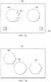
- FIG. 3 ashows an image for vision testing made up of multiple shapes in which one shape, a circle, is different from the other two, which are hexagons;
- FIG. 3 bshows an image similar to the one of FIG. 3 a , but where the shapes have been moved to other locations on the screen to avoid creating a point of fixation;
- FIG. 4 ashows a circle with pre-defined contrast as a function of radial dimension
- FIG. 4 bshows a modulated circle with pre-defined contrast as a function of radial dimension
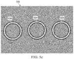
- FIG. 5 ashows a first three-way selection test with two circles and one modulated circle, all the shapes having pre-defined contrast as a function of radial dimension, and the modulated circle having strong modulation;
- FIG. 5 bshows a second three-way selection test with two circles and one modulated circle, all the shapes having pre-defined contrast as a function of radial dimension, and the modulated circle having moderate modulation;
- FIG. 5 cshows a third three-way selection test with two circles and one modulated circle, all the shapes having pre-defined contrast as a function of radial dimension and the modulated circle having slight modulation;
- FIG. 6shows a flow chart showing some elements of how a vision test routine may be controlled
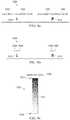
- FIG. 7 ashows a graphical result of a shape discrimination vision test
- FIG. 7 bshows a graphical result of a shape discrimination vision test that includes freebies
- FIG. 8 ashows a quantitative result presentation for a shape discrimination vision test
- FIG. 8 bshows a numerical example of a quantitative result presentation for a shape discrimination vision test
- FIG. 8 cshows a log MAR gray scale result presentation.
- the handheld device 100may include a case 102 , a display 104 , a cursor control 110 , a fingerprint sensor 114 , a camera 112 , a first button 106 , a second button 108 , a speaker 120 , a microphone 122 , a power connector 116 , and an interface port 118 .
- the display 104may include touch-screen and/or multi-touch capability so that the handheld device 100 may be controlled by touching the display 104 in various locations or manners within certain timeframes.
- the fingerprint sensor 114allows the handheld device 100 to identify the person using it (referred to as a user).
- identifying number or code for the specific handheld device 100might be beneficially marked or engraved somewhere on or inside the case 102 or other location of the handheld device 100 .
- Additional information regarding the user or the specific handheld devicesuch as its date code, manufacturing date, serial number, and other information might also be beneficially marked, engraved, or otherwise indicated on or inside the handheld device 100 . Warning messages, reminders, safety warnings and other information may also be marked on or inside the case 102 .
- the cursor control 110is a button that may be pressed to move a cursor across the display 104 and position it in a desired location. Pressing the cursor control 110 may also be used to trigger operations and to control the handheld device 100 . Alternative implementations of cursor controls including track balls, joysticks, touch pads, and other approaches may also be used in place of the cursor control 110 as shown in FIG. 1 a .
- the first button 106 and the second button 108may be used to control the handheld device 100 and to operate functions of the handheld device 100 .
- the handheld device 100may be operated through manipulation of the display 104 if a touch-screen or multi-touch capability is included, through the cursor control 110 , through the fingerprint sensor 114 , through the first button 106 and through the second button 108 . Additional buttons and controls are possible including buttons and controls on the sides and back of the handheld device 100 . It is also possible that the handheld device may include only one button, or no buttons at all. In addition, some embodiments of the handheld device 100 may include accelerometers, gyroscopes, or tilt sensors to monitor motion, rotation, and orientation of the handheld device 100 so that the handheld device 100 may be responsive to how it is held and physically oriented or moved.
- the handheld device 100may also include a microphone 122 and audio processing capability to so that voice or sound commands may be used to control it.
- the handheld device 100may include a speaker 120 , buzzer, vibrator, or other audible or physical signaling devices so that it can send messages and information to the user. Audible commands may benefit from use of a volume control that could be adjusted through the handheld device's 100 user control functions.
- the camera 112may be used to observe gestures, signals, sign language, and other symbols and movements of the user to control the handheld device 100 as well.
- Gestures involving actual motion of the handheld device 100may be monitored with a motion sensor, accelerometer, or other techniques. It is also possible to include additional buttons, displays, an external mouse or trackball, and other forms of input devices. It is also noted that haptic, audible, or other feedback such as a click, buzz, vibration, jog, or other signal delivered on each button press, touch-screen or multi-touch press, or other activation of an input mechanism to the handheld device 100 may be beneficial to acknowledge the user's input and assure them that the handheld device 100 has or will respond to their inputs.
- the case 102 of the handheld device 100may be constructed from metals, plastics, or other materials. While not shown in FIG. 1 a , the handheld device 100 may include removable panels on its front, back, or sides to allow batteries, memory cards, or optional accessories to be installed, connected, or removed.
- the power connector 116allows the device to be powered from an external electrical power source that may supply AC or DC power to the handheld device 100 .
- Some interface ports 118(such UNIVERSAL SERIAL BUS (USB®)) may also be capable of supplying power to the handheld device 100 .
- Interface port 118allows the handheld device 100 to be connected to an external host computer, external cameras, external calibration or test equipment, external accessories, or other systems or devices the user may desire to connect it to.
- the interface port 118 or the power connector 116could be configured to supply battery power from the handheld device 100 to an external device or interface connected to them.
- the interface port 118may be constructed from multiple physical interfaces and protocols. Some examples are USB®, P1394, Ethernet, RS232, and many other possible interfaces.
- the handheld device 100may include wireless connectivity. BLUETOOTH®, IEEE802.11, ZIGBEE®, and many other wireless communications protocols and radio electronics may be included in the handheld device 100 .
- the wired and or wireless connectivity of the handheld device 100allows it to send information to a network service, host computer, or other computing device; and also allows for calibration, configuration, test protocols, software updates, and other useful information to be sent from a host computer or other data processing device or interface to the handheld device 100 .
- the procedure for allowing the handheld device 100 to either send data out over its wired or wireless interfaces or to receive information from other sourcesshould normally include security features to ensure that the user's information and privacy are not compromised and also to ensure that configuration, calibration, and other important factors of the handheld device 100 operation cannot be compromised illicitly or accidentally.
- the handheld device 100may be beneficially battery operated so that it can be used in a portable fashion in many locations when and where it is convenient for the user. Additionally, the handheld device may use power supplied to it over the interface port 118 , the power connector 116 , through wireless power sources, or through other possible ways of provide power to the handheld device 100 . In the case of operation from an internal or external battery, the handheld device 100 may beneficially include capability to alert the user of the amount of charge available from the battery and alert the user when battery charging is needed. The handheld device 100 may also check the battery level before a vision test is begun to ensure that adequate energy is available to complete the test so that a test is not interrupted due to loss of power. The handheld device 100 may also include software routines constructed so that in the event of a sudden power loss the information stored in the handheld device 100 such as prior vision test results and other information is not corrupted or lost.
- the handheld device 100is used to provide a vision test suitable for detected eye diseases and to monitor their present status or severity. As some vision tests are sensitive to the distance from the user under test to the display device being observed, it may be important that the handheld device 100 operate in a fashion that ensures that each test sequence is undertaken at an appropriate viewing distance. There are several options for how this can be achieved. First, the camera 112 may take a picture or even continuously monitor a video sequence of the user and make appropriate measurements from the image to ensure that the user is at an acceptable distance from the handheld device 100 . An example of use of a camera image 150 to determine viewing distance is illustrated in FIG. 1 b . In FIG.
- a camera image 150 of a user's face 154is shown inside the camera's 112 image boundary 152 .
- a horizontal image dimension 156 and vertical image dimension 158are shown.
- Dimensions between some features of the user's face 154are also shown. These are the distance between the pupils 160 , the distance between the outer eye sockets 162 and the dimension between the pupils and the bottom of the nose 164 . It is noted that for the purposes here of determining viewing distance that dimensions of the user's face 154 that are substantially unchanged by dress, mood, hairstyle, or other variable factors are preferred. That is, dimensions such as the distance between the pupils 160 are preferred over more variable dimensions such as the opening between the sides of the user's hair.
- a user's face 154may be used in addition to those shown specifically in FIG. 1 b .
- Such a technique for monitoring the distance the user is from the handheld device 100may benefit from calibrating the actual dimensions of the user's face 154 to be used before testing begins.
- the handheld device 100can compensate for the actual size of the facial features of a specific user and more accurately estimate the distance the user is subsequently from the handheld device than would otherwise be possible.
- the camera 112 opticscould be calibrated against an object of known physical size, for example a ruler, placed at a know distance from the camera so that a reference image can be collected against which images may be compared. It is noted that the size of a dimension of the user's face 154 (or any other object for that matter) in a camera image 150 may not be a linear function of the distance it is from the camera 112 .
- non-linear correction factors or look-up tablesmay be beneficial in accurately computing the viewing distance from analysis of a given image 150 .
- the camera 112includes a zoom capability or other variable optics, it may be beneficial to take distance measurements with the camera 112 set to a known and fixed level of zoom every time such measurements are taken. Alternatively, variations in zoom could be accounted for in the distance computation.
- the handheld device 100may signal to the user through a visible, audible, or other way that he or she is either too close or too far away.
- the handheld device 100may not continue operation of the testing until the user has positioned himself or herself at an appropriate distance so that accurate and reliable testing is substantially ensured. If the camera 112 or some other means of monitoring the distance to the user from the handheld device 100 that can generate an image of the user is used; then it is further possible for the handheld device 100 to ensure that the test is being undertaken correctly. For example, in some vision tests, it is critical that the user cover one eye and undertake the testing one eye at a time.
- the camera 112can be used to monitor the user and ensure that the user has the correct eye covered for each test.
- the camera 112can also ensure that the same person is taking the test throughout the test sequence and the image of the user can be compared to images from past tests to ensure that the person taking the test is indeed the correct person.
- Other informationsuch as ensuring that the user taking the test is awake and upright and is holding the handheld device at a proper orientation can also be checked.
- the handheld device 100may automatically compensate for differences in desired viewing distances for some or all of the tests provided. That is, by monitoring how far the user is from the display 104 , the handheld device 100 may compensate for some variations in the viewing distance by adjusting the size of the test image presented in the display 104 or by varying other aspects of the test image (for example, viewing distance may also be compensated to some degree with the sharpness of the test image or by other factors). By automatically compensating for changes in viewing distance, the handheld device 100 may make it easier for a user to take their test. Instead of compensating for viewing distance by altering the size or other features of the test image, the handheld device 100 may also account for alternative viewing distances by scaling the user's resultant test score appropriately. And, of course, combinations of ways to automatically compensate for differences in viewing distance may also be applied.
- Visible glare that may appear on the display 104 of the handheld device 100may be a substantial problem for accurate vision testing if it obscures test images and makes it difficult for the user to distinguish the images provided on the display 104 .
- Use of a matte finished display (or other type of display that reduces glare) to reduce glaremay be beneficial.
- the camera 112may be used to sense ambient light conditions and alert the user to reduce ambient light or move to another location if too much ambient light is present that may result in glare or otherwise cause issues with vision testing. Scratches, smudges, chips, and other damage or contamination of the display 104 may also make accurate vision testing difficult.
- Use of a display 104 with a hard coating to avoid damage or with a screen protection filmmay be beneficial.
- a matte finishmay be beneficial, so a matte finished screen protection film (or other glare reducing film) may be desirable.
- the handheld device 100may at times remind the user to clean and wipe off the display 104 .
- auxiliary displayssuitable for use with the handheld device 100 include LCD display panels, CRT displays, light processing display devices, head mounted displays, binocular display devices, virtual reality viewers, and many other types of displays.
- LCD display panelsCRT displays
- light processing display deviceshead mounted displays
- binocular display devicesvirtual reality viewers
- many other types of displaysinclude LCD display panels, CRT displays, light processing display devices, head mounted displays, binocular display devices, virtual reality viewers, and many other types of displays.
- pico-projectorsSuch a pico-projector may be physically integrated into the handheld device 100 or may be used as an external separate device connected to the handheld device 100 through a wired or wireless communication link.
- the handheld device 100may include hardware and software to ensure that proper viewing distance and display properties are available so that a reliable test may be completed.
- images used for regular purposesmay be displayed on a wide variety of available displays, the handheld device 100 might only send images or video for vision testing to displays that it can ensure are suitable for good quality testing. This requirement may impose the need for additional connectivity to an auxiliary display and also additional calibration and security features if the auxiliary display is to be used for vision testing.
- the functions of the handheld device 100 shown in FIG. 1 amay also be incorporated into electronic handheld devices that are already used for other functions. That is, the function delivered by the handheld device 100 may be implemented on a portable game console, a cellular phone, a personal digital assistant, a tablet computer, a netbook computer, a notebook computer, a blood glucose meter, or many other electronic devices. It is noted that there may be some benefit to using devices with somewhat larger displays as a greater area of the retina can be covered in vision testing (this may be more important for some vision disorders, but will be less important for others). However, larger devices with larger displays are normally less portable and may be more expensive, so tradeoffs of cost and convenience versus retina test coverage may need to be made.
- the ability to combine many functions together into a single deviceallows for convenience for the user and also allows for beneficial combined functionality in some cases.
- the handheld device 100 of FIG. 1 aincludes the function of a glucometer, the user can record their blood glucose level when each vision test is taken so that a more complete record of vision capability and blood glucose can be generated (and this may be especially beneficial to users at risk with regard to diabetic retinopathy).
- the handheld deviceincludes a positioning technology such as the Global Positioning System (GPS)
- GPSGlobal Positioning System
- the records of vision testingcan be location stamped so that the user can more easily remember where they took each test and what the testing conditions were.
- the handheld device 100can easily include calendar and clock functions so that test results may also be time and date stamped.
- a Landolt C 408 test imageis shown.
- the Landolt C 408 testis suitable for use with the handheld device 100 already described.
- the test imageincludes a display 104 outer boundary 402 , soft keys 404 , and reference lines 406 .
- the Landolt C 408is rotated in 90 degree increments so that the “open” side of the “C” points to the right (as shown in FIG. 2 a ), to the left, upwards, or downwards.
- the userperforms the test by pressing the soft key 404 in the direction in which the Landolt C 408 has its opening.
- the Landolt C 408 testprovides for a vision acuity check.
- the testcan be easily extended to include additional angles of orientation for the directions in which the “open” side of the “C” can appear in the course of a test.
- the display 104 outer boundary 402is the limit of the display 104 area used for the test. It is noted that depending on the actual design of the handheld device 100 , the outer boundary 402 may be less than the physical limit of the display 104 . For example, to test for a high level of vision acuity, the Landolt C 408 may appear rather small in the handheld device 100 display 104 , so the entire display 104 area may not be used for some tests.
- the reference lines 406are optional for the Landolt C 408 test and are included to better define the region in which the Landolt C 408 is rotated.
- the soft keys 404may be pressed manually by the user with their fingers or with a stylus if that is preferred. And, instead of using the soft keys 404 for the user to provide their input on the orientation of the Landolt C 408 , this may be indicated by touching the touch-screen at a pre-defined location (perhaps in the “opening” of the C), by strokes on the touch-screen, by gestures monitored by the camera 112 , by movements of the handheld device 100 , through voice signals, or by other techniques.
- the Landolt C 408 testis based on a user's ability to distinguish the orientation of the “C” as a function of how large the image is presented. Of course, many other shapes may be used to create similar tests. Another common similar test is known as the “tumbling E” test. The “tumbling E” test is very similar to the Landolt C 408 test, the only key difference being the use of a letter E instead of a letter C. Of course, a very wide variety of shapes, such as circles, squares, triangles, and many other shapes that include some distortion, modulation, or other feature that allows their orientation to be specific so that a user can be challenged to identify it.
- FIG. 2 ban Amsler Grid test image is shown.
- the Amsler Gridconsists of grid segments 412 arranged in a regular rectangular grid within the outer boundary 402 .
- a center feature 414is provided for the user under test to fixate on while identifying any missing, wavy, or distorted grid segments 412 .
- a touch-screen capability in the display 104it is very easy for the user to indicate which grid segments 412 are missing, wavy, or distorted simply by pressing on the display 104 above such a grid segment 412 .
- multi-touch capability in the display 104the user may be able to indicate the location of missing, wavy, or distorted grid segments even more quickly and conveniently.
- a missing grid segment 412may signal a more severe or advanced condition than a wavy or distorted grid segment 412 , so information for each level of condition can be collected separately and tracked automatically.
- the soft key 404 shown in FIG. 2 bcan be used to indicate that the user sees all grid segments 412 normally.
- the Amsler Grid testlike all tests described here, can be performed with different light intensities, colors, feature sizes, line weights, contrasts, and other image parameters to test the sensitivity and capability of the user's vision in a wide array of conditions.
- FIG. 2 cshows an image for vision testing that includes a right circle 420 and a left circle 416 either of which may include a modulated region 418 .
- the outer boundary 402serves the same function as in the prior figures.
- the soft key 404is pressed by the user under test to indicate which of the two circles, the right circle 420 or the left circle 416 has a modulated region 418 .
- this selectioncan be done directly by touching the circle that has a modulated region 418 if a touch-screen display is used.
- other methods of capturing this input from the user based on visible gestures, movement of the handheld device 100 , sounds, etc.are also possible.
- the modulated region 418By changing the amplitude and location of the modulated region 418 and whether it appears on the left circle 416 or the right circle 420 it is possible to determine the user's ability to differentiate the presence or absence of a modulated region 418 .
- other shapesbesides circles such as hexagons, squares, and other shapes can be used.
- the modulated region 418need not be a smooth curve as shown in FIG. 2 c , but may be triangular, rectangular, or of other shapes.
- the modulated region 418may also appear at any angle around the circle including the top, the bottom, either side, or at other angles.
- FIG. 2 cshows two circles, it is possible to create a similar test using three, four, or any number of circles or other shapes. With a larger number of circles or other shapes used in vision testing, the user selects from a broader number of choices and this may create a test with desirable attributes (the test may run faster, have more redundancy, be more accurate, or have other desirable attributes).
- FIG. 3 ashows an image for vision testing suitable for use on a handheld device 100 made up of multiple shapes in which one shape, a circle 420 , is different from the other two, which are hexagons 424 .
- the display boundary 402is shown for reference.
- this vision testthe user selects the shape that is different from the other two by touching it on a touch-screen display 104 .
- this inputcould also be done with a keyboard, mouse, cursor controller 110 , soft keys, audible signals, gestures, movement of the handheld device 100 , or by other techniques.
- FIG. 3 ashows an image for vision testing suitable for use on a handheld device 100 made up of multiple shapes in which one shape, a circle 420 , is different from the other two, which are hexagons 424 .
- the display boundary 402is shown for reference.
- the userselects the shape that is different from the other two by touching it on a touch-screen display 104 .
- this inputcould also be done with a keyboard, mouse, cursor controller
- FIG. 3 blike FIG. 3 a , includes a display boundary 402 , a circle 420 and two hexagons 424 . However, the locations of the circle 420 and hexagons 424 have shifted inside the display boundary 402 . This is done intentionally to avoid the user fixating on one location in the test image and to encourage use of the user's broader vision. As with FIG. 3 a , the user when viewing FIG. 3 b would once again correctly select the circle 420 as the shape that is different from the other two.
- FIGS. 3 a and 3 bused circles 420 and hexagons 424 for shapes to be compared, may different shapes may be used. Squares, triangles, octagons, rectangles, and many other shapes can be applied. And while the circles 420 and hexagons 424 were relatively easy to distinguish from each other, shapes may be used that have only subtle differences so that the user is challenged to discriminate between them. In a vision test, a variety of easier and more difficult challenges in shape discrimination may be presented to the user so that the user's capability to detect small differences in shapes can be assessed.
- the subsequent images used for such testingmay progressively become more difficult to distinguish as testing progresses, they may become more difficult based on some rules regarding the ability of the user to discriminate shapes in prior images, or may even be presented to the user randomly. Very many sequences for presenting more or less difficult shapes to discriminate are possible. It is also possible to make use of shapes that are turning, moving, changing size, rotating, or otherwise being altered in time as the test is taken.
- a circle 604is shown that has pre-defined contrast as a function of radial dimension.
- the circle 604is shown as a light circular region on a gray background. It also includes dark halos 610 and light halos 612 on both the inside and outside of the light circular region. It is noted that the contrast level of the dark halos 610 and the light halos 612 are a function of the radial dimension of the point of consideration on the halo to the center of the circle 604 .
- the use of a circle 604 that has pre-defined contrast as a function of radial dimensionis beneficial in further encouraging the user of a vision testing system to avoid a specific point of fixation and instead employing their broader vision capability.
- shapes with pre-defined contrast as a function of radial dimensionalso relaxes the dependence of test results on viewing distance.
- shapes including pre-defined contrastsuch as the circle 604 of FIG. 4 a were used in the test described in FIGS. 3 a and 3 b .
- some benefit in the accuracy of the testingmay be achieved.
- many shapes including pre-defined contrastmay be used instead of circles. Squares, triangles, ovals, ellipses, and many other shapes may be used.
- the shapesneed not be regular (that is, irregular shapes may also be used) and it is not even needed that they be closed curves.
- other aspects of the shapesuch as how sharp or fuzzy the lines are, brightness, color, and any other aspect of how the shape is presented may be varied.
- a modulated circle 608is shown that has pre-defined contrast as a function of radial dimension.
- the modulated circle 608is shown as a light region on a gray background. It includes dark halos 610 and light halos 612 on both the inside and outside the light region.
- the modulated circle 608 of FIG. 4 bis very similar to the circle 604 of FIG. 4 a with the exception that it has a modulated radius and is not a regular circle. Note that when the modulated circle 608 was formed, the pre-defined contrast as a function of radial dimension was applied first and the circular shape was then modulated so that both the light region and the dark halos 610 and light halos 612 were all modulated all together.
- 4 bis a smooth curving change in radius as a function of angle, but many other modulations such as triangular modulations of radius, sinusoidal modulations of radius, and many other modulation functions can be applied. It is also possible to create irregular shapes and even shapes that are not closed curves for shape discrimination testing.
- FIGS. 5 a , 5 b , and 5 ca sequence of vision test images 700 that may be utilized on the handheld device 100 are shown. These would normally be shown to a user in turn and the next image would be shown once the user responds to the image being shown to them presently.
- the test images 700are three-way selection shape discrimination tests. In the first test image 700 shown in FIG. 5 a , two circles 604 and a modulated circle 608 , all of which have pre-defined contrast as a function of radial dimension, are shown. Similar to the vision test described in FIGS.
- the three-way shape discrimination test image 700is viewed by a user who selects which of the three or more shapes (in this embodiment three shapes are shown, but more can be used if desired) that is different from the others. This selection may be done by touching the display 104 over the shape being selected if a touch-screen or multi-touch display is used, or may be done with buttons, a mouse, cursor controls, audible inputs, gestures, or other techniques.
- the different shapeis clearly the modulated circle 608 .
- FIG. 5 bthere are still two circles 604 and one modulated circle 608 , but the modulation level of the modulated circle 608 has been reduced so that it is harder to distinguish from the circles 604 .
- the order of the shapeshas been changed so that the user must recognize that the modulated circle 608 is now to the right and no longer in the center location as it was in FIG. 5 a and the relative location of all the shapes has been shifted slightly upwards, downwards and/or side-to-side to avoid causing the user to fixate at a specific point in the image.
- the modulation phasehas been changed randomly to minimize the cues of localized deviation from circularity from one test trial to another. That is, the modulated circle 608 has also been rotated randomly so that the phase of the modulation may not provide any visual cues.
- the usermay then be shown the test image of FIG. 5 c in which the modulated circle 608 is now to the far left and the modulation level is very small so that it is rather difficult to notice that it is different from the circles 604 .
- the vision testing approach shown in FIGS. 5 a , 5 b , and 5 coffers several advantages. First, since it is desired that the user not fixate on a specific point in the images, there is no loss of accuracy if the user shifts their vision. In fact, it is desirable that the user make use of their broader vision. Second, the use of shapes such as the circle 604 and the modulated circle 608 that have contrast that varies with radial dimension makes the test less sensitive to small blurs in the display 104 that may be caused by manufacturing defects, dust, smudges, streaks, or other dirt and contamination.
- the testis less sensitive to imperfections of the visual accommodation of the user (that is, whether or not the user has good focusing ability and has a proper lens prescription if needed), and for substantially the same reasons, the test is also less sensitive to viewing distance from the user to the display 104 .
- the embodiment shown in FIGS. 5 a , 5 b , and 5 cused circles 604 and modulated circles 608 , but other shapes (such as squares, triangles, irregular closed and open curves, etc.) that are somewhat blurred, have halos, have variable contrast, have shading, have lighter and darker pixels, or are otherwise made somewhat fuzzy may also provide good results as vision test images.
- such shapesmay be presented in a wide variety of colors, contrast levels, brightness levels and with other alterations to their construction and presentation.
- FIG. 6shows a flow chart 800 showing some elements of how a vision test routine may be controlled through a computer program. While many program control flows are possible for the operation of the handheld device 100 , several novel features of the flow chart 800 are included to help ensure accurate and reliable testing results.
- First step 802indicates the beginning of the flow chart and the INPUT line 804 indicates that ID (identification) information for the user of the system and profile information about that person is made available to the program. This information may be received from prior inputs from the user, other programs, configuration information loaded by a health care provider or computer system administrator, over the internet, or via other means.
- First control step 806may check the user's ID against the information received by the program from the INPUT line 804 and may verify the user's identity.
- the identity information usedmay include a photograph of the user, a password, electronic fingerprints, or other methods of verifying identification.
- the handheld device 100may include a camera, fingerprint sensor, fundus camera, and means to collect other biometric data, there are potentially many ways to verify the user's identification.
- this biometric datamay be collected and stored in the handheld device to note the user's condition of health. Additionally, the biometric data may be date-stamped so that it can be associated to the user's health condition at a particular time and associated with particular vision testing results. Examples of biometric data include, without limitation, pupil dilation, iris color, eyelash growth, heart rate, blood pressure, ptosis, and results of other health condition measurements.
- user informationmay be updated once the user's identification has been verified.
- the user informationmay include information such as their preferred language, age, race, sex, blood pressure, glucose reading, resting heart rate, weight, medications, dosage levels, and other health related information.
- Biometric information, the results of health measurements and/or medical tests, the time and date of the dosage levels at which medications have been administered, side-effects the user may be experiencing from medications or treatments, and observations or comments the user may have regarding their state of healthmay be updated in second step 808 as well.
- auxiliary devicesuch as a glucometer, medication dosing aid, or other instruments and may be entered into the handheld device either manually by the user or automatically through an electronic interface. Medication dosing could also be recorded by the handheld device as a video to create a record of each medication dosing.
- the user informationmay also include other information about the user such as their email address, phone numbers, information regarding how to contact their health care provider, and other information the handheld device 100 may need to facilitate care for the user. It is noted that users may be likely to achieve the most accurate results when using their most comfortable language, hence, multilingual support based on the available user information may be important for the handheld device 100 .
- First control step 806may also check to ensure that the software loaded on the handheld device 100 is a recent version and has not expired.
- the handheld device's 100 softwaremay include expiration dates or a total number of times the software can be used before it is mandatory that the software be updated. This is an important safety feature as it ensures that old versions of the software cannot be used for a long time. Old software may have bugs that have been corrected in newer versions or newer software may have enhancements that make the vision testing more accurate, reliable, or beneficial in other ways. If the software version operating on the handheld device has expired or is not usable for some other reason, first control step 806 may pass control to exception handling service routine 828 , where the user may be directed to download updated software, request customer service, or otherwise address the situation.
- the handheld device 100may simply access the internet according to a regular schedule and check for possible updates to be downloaded and installed. Alternatively, if specific handheld devices 100 are registered with a host computer system, updates may be sent to the specific handheld devices 100 as soon as they are ready for use.
- Second control step 810pretests, determines light levels, and self-tests handheld device 100 .
- the pretestmay be included to verify that the user is in a correct state to allow a valid vision test to be completed. This may be important to ensure that the user is alert, awake, not under the influence of medications, drugs, or alcohol, and is generally ready for the vision test.
- the pretestmay be a short game, coordination check, or other check where the result is compared to past results for the user from prior testing.
- the handheld device 100may check the ambient light levels to ensure that the user is in an environment adequate for the vision testing. This may normally be done using the camera 112 to sense the ambient light levels, but may also be done with other light detectors such as a photodiode.
- Second control step 810may also include a device self-test.
- the handheld device 100may check its memory for proper functionality, and may check its interfaces and operating parameters for acceptable conditions.
- the self-testmay direct the user to further test or calibrate the handheld device 100 if a problem is detected.
- second control step 810has a valid outcome, a user-specific vision test or a standard test may be generated or accessed by the system software.
- the profile information from the INPUT line 804 , the user information received in the second step 808 , and possibly results from prior vision tests for the usermay be used to determine what vision tests should be included. For example, a user with macular degeneration may benefit most from different tests than a patient with diabetic retinopathy.
- a user specific test generationis generated in third step 812 and once the user specific test is ready, fourth step 814 runs the test while monitoring the user's viewing distance, which eye the user has covered, and possibly other parameters.
- These other parametersmight include monitoring an accelerometer or other motion sensor to sense if the user is shaking or otherwise moving more than would be acceptable for an accurate test result. It may also include monitoring of the ambient light levels, and/or checking for the presence of glare. The time the user takes for each test input may also be monitored so that interruptions of the testing or very long response times may be noted as possible indications of an invalid test. If any situations arise during the vision test that may compromise the accuracy of the results, the user may be notified to correct them. And if a correction is not made, the results may be marked to indicate they were received under questionable operating circumstances.
- Some means to allow the user to pause or abort testingmay be included in fourth step 814 functions, and also, may be included in other areas of the flow chart 800 as well. This is beneficial as the user may be interrupted with a phone call, visitor, or have some other reason to want to stop testing immediately and resume later. The ability to pause and resume testing may be limited to short interruptions as the reliability of the test may be compromised if the user's condition, ambient conditions, or other factors have changed since testing was paused. Consequently, a time out function may be necessary if a pause feature is included. It is noted that records of partial tests, aborted tests, and paused tests (whether or not they timed out) may be stored in the handheld device 100 , but should be properly recorded to ensure that they are not confused with valid and complete test results.
- Third control step 816checks to ensure that results from the test run in step 814 are reliable. This includes checking to ensure that all the parameters being monitored during the course of the test, such as viewing distance and proper eye coverage, etc., are nominal. And it may also include analysis of the test results to ensure consistency. That is, the vision test may be designed to include some redundancy in testing so that user responses on various tests are consistent with each other and indicate that the user took the test properly and was not guessing, making random inputs, or otherwise taking the test capriciously. One way this may be achieved is to occasionally present the user with a “freebie” test. That is, while the normal course of a vision test may be to subsequently make it more difficult for the user to distinguish the features of the test image (this was illustrated in the explanation of FIGS.
- Third control step 816may also check specifically for false negative test results. False negative results are especially troublesome as they may indicate to the user that their condition is okay, when they may actually have a vision condition that needs attention. A false negative may be the result of the user cheating on the test by moving the handheld device 100 closer to them than they should for some test decisions, studying the test image for a long time, asking a person with them what answer to provide, and possibly other ways. Additionally, a false negative may occur if the test is not specifically sensitive to the user's condition or possibly for other reasons. For this reason, it may be important to ensure that all operating parameters (user condition, ambient light conditions, response timing, etc.) are consistent with accurate testing before a negative test result is provided.
- third control step 816passes control to fourth control step 818 which may determine whether the test results show a significant change in vision. As noted previously, a substantial benefit of vision monitoring may be gained in noting if changes in a user's vision have occurred from previous testing. Hence, fourth control step 818 may check specifically for this and direct the program to fifth control step 820 which checks if an additional test is needed if significant changes may have occurred. If fifth control step 820 finds that prior test results are not consistent (or if there are no prior results to compare to), a new user-specific test may be generated by third step 812 so that the user is not influenced by remembering how he or she responded to the prior test.
- Fourth control step 818 and fifth control step 820may also make other assessments. For example, if this is the first time a new user is receiving the test, it may direct control to complete multiple tests simply to verify consistency of the test readings and to more rapidly build a database of results for the user.
- fourth control step 818passes control to fifth step 822 where a data archive kept in the handheld device 100 may be updated with the new results and results may be provided to the user.
- controlpasses to fifth control step 820 where the results of the previous test, if one has already been completed, are compared to the results of the present test. If a sufficient number of tests (the system could be configured for any number of additional tests as desired) show consistent results, control also passes on to fifth step 822 for data archiving and presentation of the results to the user.
- the Fifth step 822may perform two very important functions. First, it updates the data archives kept in the handheld device 100 .
- the archivesmay include all information about the testing that was just completed. For example, the date and time the test was taken, identification of the handheld device 100 used, where the test was taken (if position information is available), how the user's identification was validated, a picture of the user, the room conditions, the distance from the user to the handheld when the test was taken, the time taken for and the result of each response the user gave in the course of the test, the length of any pauses in the testing, any invalid results, any special conditions that arose, the results of all tests given, and other information may be archived.
- Additional informationsuch as screen shots of the handheld device's 100 display 104 at various points of the testing, and especially the screen shot presented to the user providing the results of their test, may also be archived.
- additional parametersmay be archived, or for some embodiments, it may not be necessary to include all the information listed here. In any case, however, sufficient information may be archived so that a substantially complete and accurate record of the testing is kept.
- the second key function of fifth step 822may be to notify the user of the results of his or her test. This may be done visually on the handheld device 100 display 104 , audibly, or by other means. But in any case, the results provided to the user may include their specific test scores and also some information about what the scores mean. That is, the handheld device 100 may assure the user that their scores are within reasonable bounds of their past scores. Or, if the user's vision has changed such that the handheld device 100 concludes that a professional evaluation is warranted, the handheld device 100 may direct the user to contact their health care provider for an evaluation. Of course, the handheld device 100 may also be used to keep track of the user's appointments including their scheduled visits with healthcare providers. So in some cases, the handheld device 100 may produce normal results for vision testing, but still remind the user that they have a regular appointment with a healthcare professional.
- the usermay benefit if they are given positive encouragement in the course of their testing and especially when their results are provided to them.
- Other information that may be beneficial to the usersuch as recommendations for a healthy diet with exercise, advertising and branding information, or other information may also be passed to the user from the handheld device 100 at multiple points through the course of its use and, in particular, when the user is provided and/or is about to be provided their testing results.
- the inspirational and other messagesmay be tailored to the user's specific preferences through information stored in the handheld device 100 . For example, if it is known to the handheld device 100 that the user is trying lose weight, some encouragement consistent with this goal may be especially beneficial. Similarly, if the user's religion is known, inspirational messages can be tailored to be appealing to them more specifically.
- Controlpasses from fifth step 822 to sixth step 824 where the testing results may be uploaded to a healthcare provider, clinical study coordinator, or other appropriate entity.
- the testing resultsmay also be uploaded to a data server.
- Users with especially acute conditionsmay want a professional to review their testing results on an ongoing basis. Or, since the handheld device 100 , could be damaged, destroyed, lost, or stolen, the user may want their results to be stored on a computer system server so that they can be recovered if needed.
- wired or wireless networking technologysuch as DSL, fiber optics, wireless LAN, wireless WAN, or other wired or wireless data transmission technologies may be used to upload the data.
- Some user'smay want email messages with their test results sent to specific email addresses and than can also be completed in sixth step 824 if desired.
- data uploaded from the handheld device 100may be used in the construction of databases of information that may be used to enhance knowledge of various testing and treatment routines. That is, if a user is known to be taking certain medication, uploading and analyzing their vision testing results allows comparison of their results with others so that a substantially complete and accurate knowledge of the effectiveness of certain treatments may be assessed.
- This informationmay be beneficial to developers of treatments and especially in the conduction of medical trials to assess the efficacy of treatments.
- business models in which companies or individuals wanting access to certain datamay financially compensate a handheld device 100 user, or a provider of vision testing technology, may also be possible.
- a health insurance providermay incentivize users to take regular tests and possibly also upload their test results in the interests of making overall disease management and/or treatment more cost effective.
- First control step 806 , second control step 810 , and third control step 816all include conditions for which negative or invalid results result in sending control to exception handling service routine 828 .
- exception handling service routine 828may direct the user to perform different functions so that proper testing can resume or be initiated. For example, if the user's identification fails, exception handling service routine 828 may simply notify the user and allow them to try again.
- the usermay be directed to test, service, or calibrate the handheld device 100 .
- Other conditionsmay be dealt with in appropriate manners as well. If the room ambient light is too bright, the user may be directed to change it. If inconsistent test results were determined and the test was deemed unreliable, the user may be notified and asked to take the test another time. If repeated unreliable results occur, the user may be directed to seek a professional evaluation from their healthcare provider. Since the handheld device 100 may make very many measurements and use very many techniques to ensure an accurate and reliable test, it is not practical to list many dozens or even hundreds of them here. However, the overall flow of the flow chart 800 makes it clear that the handheld device 100 will use many techniques to ensure accurate and dependable results.
- the handheld device 100may include alarm functions to alert a user that they have a scheduled vision test to complete. In such a case, the handheld device 100 may start up automatically and send audible and/or visible or other signals to the user to remind them to take their test.
- the handheld device 100may also include other calendar, appointment management, or other user convenience software. Additionally, it may be synchronized or updated by other calendar management software so that the user may conveniently keep track of their personal appointments along with their testing schedule, heath care provider appointments, medication schedule, reminders to take vitamins and/or exercise, and other aspects of their overall care.
- FIG. 7 ashows a graphical result of a shape discrimination vision test 900 .
- the first trial imageis represented by the first cross 901 which is shown at an elevated modulation level as it is positioned at a high level on the vertical axis 902 .
- the vertical axis 902represents modulation level and this is clear in FIG. 7 a as the words “Modulation Level” are shown as a title on the vertical axis 902 .
- Modulation level as shown in FIGS. 7 a and 7 brefers to the amplitude of the modulation of a modulated shape such as the modulated circle 608 of FIG. 4 b , or FIGS. 5 a , 5 b , and 5 c .
- Subsequent trialsare represented in FIG.
- the mistake trial 912illustrates this and shows that if a mistake is made, the modulation increases on a subsequent trial. Once correct responses to a trial resume, the modulation will again decrease on subsequent trials. It is noted that an amount modulation increases 914 when a mistake is made may be different from an amount modulation is decreased 916 when a correct answer is entered. After some number of trials, an accurate representation of the limit of the user's modulation threshold 906 may be estimated.
- the modulation threshold 906may be determined from the data in a number of ways. One approach would be to take the modulation threshold 906 to be the level at which an equal number of decreasing and increasing modulation trials (i.e., an equal number of mistakes and correct result entries) are made over some number of past trials.
- the modulation threshold 906could be taken as the level at which an equal number of correct results and mistakes occurred over the last four trials.
- the modulation threshold 906might also be taken as the modulation level that was crossed with correct (or incorrect) answers some fixed number of times.
- the modulation threshold 906is a level that was crossed three times with correct answers.
- the third correct crossing 918 in FIG. 7 aillustrates this.
- the modulation thresholdmight also be taken as the mean of several reversals (the level changes from correct to incorrect or from incorrect to correct).
- Another way to determine the thresholdmight be to fit a mathematical function that describes the threshold behavior of the visual system to the percent correct rates at various testing levels.
- the reliability of the threshold estimationmay be assessed by analyzing fitting parameters and by comparing threshold values obtained with various threshold determination methods.
- FIG. 7 bshows a similar graphical result of a shape discrimination vision test 900 to that shown in FIG. 7 a , but freebie 920 and freebie 922 are included.
- a freebie trialis a trial in which the user is presented with a rather large modulation with the expectation that it should be an easy test for them to answer correctly.
- observation of the user's replies to a freebieis one way of ensuring that the user is actively engaged in the test and isn't just guessing.
- Another measure of the user's ability to correctly take the testis the consistency of the level at which mistakes occur as the test trials progress. In FIG.
- the first mistake trial 912 , the second mistake trial 924 and the third mistake trial 926all occur at similar modulation levels. Consequently, the confidence in the modulation threshold 906 level for the user is relatively high as the user appears to be consistent in the level of modulation reached before a mistake is made.
- Other ways of assessing the user's consistencyinclude consistently correct answers for higher modulation levels above the modulation threshold 906 , and other possible statistical or other mathematical analysis techniques. It is noted that the amount the modulation is varied after the occurrence of a freebie may resume from the level of modulation prior to the freebie, may decrease from the level of modulation prior to the freebie assuming the freebie trial was answered correctly, or may follow other rules for variation of modulation including random variation of modulation rules and other rules.
- FIG. 8 aillustrates a quantitative result presentation 1000 for providing results to the user and/or tabulating results of a shape discrimination test.
- the L 1010indicates that the results above it are for the left eye and the R 1012 indicates that the results above it are for the right eye.
- the % Mod Result for the left eye 1002is the modulation threshold 906 shown in FIGS. 7 a and 7 b for the left eye of the user and the % Mod Result for the right eye 1006 is the modulation threshold 906 for the right eye of the user.
- the % Mod Result for the left eye 1002 and the % Mod Result for the right eye 1006may be presented as simple percentages of modulation, proportions of modulation to circle radius (or another key dimension whatever shape is used), in the well-known MAR (Minimum Angle of Resolution) measure, or in log MAR (the logarithm of MAR), or in other quantitative or relative measurement formats.
- the left eye consistency score 1004 and the right eye consistency score 1008are consistency measures as previously discussed for the users left eye and right eye tests respectively. Providing a consistency score of some sort to the user coaches them on their test taking ability and reinforces the need to take the vision test carefully and actively.
- the left eye consistency score 1004 and the right eye consistency score 1008are much like video game scores in that they tell the user how well they took the test. Storing the left eye consistency score 1004 and the right eye consistency score 1008 in the handheld device's 100 memory and making it a part of the test archive for the user is useful as it provides an indication of how well the test was taken, and hence, to what level the result may be trusted.
- an example quantitative result presentation 1000is provided with numerical example results for the % Mod Result for the left eye 1002 and the left eye consistency score 1004 shown above the L 1010 ; and with % Mod Result for the right eye 1006 and a right eye consistency score 1008 shown above the R 1012 .
- the left eye consistency score 1004 and the right eye consistency score 1008 as presented in FIG. 8 bare not numerical, but are represented as ++ and +, respectively, indicating relatively how consistent the user was in taking the tests.
- Numerical scoresare also possible, but relative scores using stars, smiling or frowning faces, different colors, or other approaches may be beneficial in providing a general indication of how consistently the user took the test.
- % Mod Result for the left eye 1002 and the % Mod Result for the right eye 1006may also be provided as relative scores if desired. Relative scores such as good/moderate/poor, normal/borderline/abnormal, and many other relative scores are possible.
- FIG. 8 cshows another example technique for result presentation.
- a log MAR gray scale 1030is shown including a title 1038 , a lower gray scale limit 1036 , an upper gray scale limit 1034 , and a gray scale 1032 .
- the title 1038identifies the result presentation of the log MAR gray scale 1030 as “log MAR Gray Scale”
- the lower gray scale limit 1036is illustrated as “ ⁇ 1.00”
- the upper gray scale limit 1034is illustrated as “1.00”.
- the gray scale 1032shows a range from white for results near the lower gray scale limit 1036 to black for results near the upper gray scale limit 1034 .
- a test scoremay be represented by using a gray level between the upper gray scale limit 1034 and the lower gray scale limit 1036 .
- the accuracy of the test scoremay be represented by the extension of that gray level, or a band of gray levels centered at the one that represents the test score. The narrower the gray level band, the more accurate or consistent the test score.
- a wide range of other options for using a segment of gray region within a gray scale 1032include showing a result presentation in which the center of a gray region represents a test score and the size, shape or other aspects of the gray region represent the consistency of the user in taking the test.
- many variants including use of variable color shades instead of a gray scale 1032varying shapes, sizes, and other variations may be used.
Landscapes
- Health & Medical Sciences (AREA)
- Life Sciences & Earth Sciences (AREA)
- Engineering & Computer Science (AREA)
- Surgery (AREA)
- General Health & Medical Sciences (AREA)
- Biophysics (AREA)
- Biomedical Technology (AREA)
- Heart & Thoracic Surgery (AREA)
- Medical Informatics (AREA)
- Molecular Biology (AREA)
- Physics & Mathematics (AREA)
- Animal Behavior & Ethology (AREA)
- Ophthalmology & Optometry (AREA)
- Public Health (AREA)
- Veterinary Medicine (AREA)
- Signal Processing (AREA)
- Eye Examination Apparatus (AREA)
- User Interface Of Digital Computer (AREA)
- Position Input By Displaying (AREA)
- Measurement Of The Respiration, Hearing Ability, Form, And Blood Characteristics Of Living Organisms (AREA)
Abstract
Description
Claims (92)
Priority Applications (3)
| Application Number | Priority Date | Filing Date | Title |
|---|---|---|---|
| US15/403,656US10765312B2 (en) | 2009-05-09 | 2017-01-11 | Shape discrimination vision assessment and tracking system |
| US16/935,055US11659990B2 (en) | 2009-05-09 | 2020-07-21 | Shape discrimination vision assessment and tracking system |
| US18/139,870US12357170B2 (en) | 2009-05-09 | 2023-04-26 | Shape discrimination vision assessment and tracking system |
Applications Claiming Priority (6)
| Application Number | Priority Date | Filing Date | Title |
|---|---|---|---|
| US17688509P | 2009-05-09 | 2009-05-09 | |
| US25115909P | 2009-10-13 | 2009-10-13 | |
| PCT/US2010/034084WO2010132304A1 (en) | 2009-05-09 | 2010-05-07 | Shape discrimination vision assessment and tracking system |
| US201113319305A | 2011-11-07 | 2011-11-07 | |
| US14/849,682US9743828B2 (en) | 2009-05-09 | 2015-09-10 | Shape discrimination vision assessment and tracking system |
| US15/403,656US10765312B2 (en) | 2009-05-09 | 2017-01-11 | Shape discrimination vision assessment and tracking system |
Related Parent Applications (3)
| Application Number | Title | Priority Date | Filing Date |
|---|---|---|---|
| US13/319,305ContinuationUS9155461B2 (en) | 2009-05-09 | 2010-05-07 | Shape discrimination vision assessment and tracking system |
| PCT/US2010/034084ContinuationWO2010132304A1 (en) | 2009-05-09 | 2010-05-07 | Shape discrimination vision assessment and tracking system |
| US14/849,682ContinuationUS9743828B2 (en) | 2009-05-09 | 2015-09-10 | Shape discrimination vision assessment and tracking system |
Related Child Applications (1)
| Application Number | Title | Priority Date | Filing Date |
|---|---|---|---|
| US16/935,055ContinuationUS11659990B2 (en) | 2009-05-09 | 2020-07-21 | Shape discrimination vision assessment and tracking system |
Publications (3)
| Publication Number | Publication Date |
|---|---|
| US20170119245A1 US20170119245A1 (en) | 2017-05-04 |
| US20190290122A9 US20190290122A9 (en) | 2019-09-26 |
| US10765312B2true US10765312B2 (en) | 2020-09-08 |
Family
ID=43085278
Family Applications (5)
| Application Number | Title | Priority Date | Filing Date |
|---|---|---|---|
| US13/319,305Active2031-12-17US9155461B2 (en) | 2009-05-09 | 2010-05-07 | Shape discrimination vision assessment and tracking system |
| US14/849,682Active2030-10-23US9743828B2 (en) | 2009-05-09 | 2015-09-10 | Shape discrimination vision assessment and tracking system |
| US15/403,656ActiveUS10765312B2 (en) | 2009-05-09 | 2017-01-11 | Shape discrimination vision assessment and tracking system |
| US16/935,055Active2030-12-25US11659990B2 (en) | 2009-05-09 | 2020-07-21 | Shape discrimination vision assessment and tracking system |
| US18/139,870Active2030-08-05US12357170B2 (en) | 2009-05-09 | 2023-04-26 | Shape discrimination vision assessment and tracking system |
Family Applications Before (2)
| Application Number | Title | Priority Date | Filing Date |
|---|---|---|---|
| US13/319,305Active2031-12-17US9155461B2 (en) | 2009-05-09 | 2010-05-07 | Shape discrimination vision assessment and tracking system |
| US14/849,682Active2030-10-23US9743828B2 (en) | 2009-05-09 | 2015-09-10 | Shape discrimination vision assessment and tracking system |
Family Applications After (2)
| Application Number | Title | Priority Date | Filing Date |
|---|---|---|---|
| US16/935,055Active2030-12-25US11659990B2 (en) | 2009-05-09 | 2020-07-21 | Shape discrimination vision assessment and tracking system |
| US18/139,870Active2030-08-05US12357170B2 (en) | 2009-05-09 | 2023-04-26 | Shape discrimination vision assessment and tracking system |
Country Status (21)
| Country | Link |
|---|---|
| US (5) | US9155461B2 (en) |
| EP (2) | EP4190226A1 (en) |
| JP (2) | JP5812986B2 (en) |
| KR (2) | KR20150068493A (en) |
| CN (1) | CN102458220B (en) |
| AU (2) | AU2010247901B2 (en) |
| BR (1) | BRPI1011373A8 (en) |
| CA (1) | CA2760694C (en) |
| CL (1) | CL2011002803A1 (en) |
| CO (1) | CO6460703A2 (en) |
| DK (1) | DK2427095T3 (en) |
| ES (1) | ES2959392T3 (en) |
| FI (1) | FI2427095T3 (en) |
| IL (1) | IL216184A (en) |
| LT (1) | LT2427095T (en) |
| MX (1) | MX2011011865A (en) |
| PT (1) | PT2427095T (en) |
| RU (2) | RU2541048C2 (en) |
| SG (2) | SG175920A1 (en) |
| SI (1) | SI2427095T1 (en) |
| WO (1) | WO2010132304A1 (en) |
Cited By (1)
| Publication number | Priority date | Publication date | Assignee | Title |
|---|---|---|---|---|
| US20200345227A1 (en)* | 2009-05-09 | 2020-11-05 | Genentech, Inc. | Shape Discrimination Vision Assessment and Tracking System |
Families Citing this family (96)
| Publication number | Priority date | Publication date | Assignee | Title |
|---|---|---|---|---|
| WO2010132305A1 (en)* | 2009-05-09 | 2010-11-18 | Vital Art And Science Incorporated | Handheld vision tester and calibration thereof |
| US8798534B2 (en) | 2010-07-09 | 2014-08-05 | Digimarc Corporation | Mobile devices and methods employing haptics |
| DE102011011767A1 (en)* | 2011-02-18 | 2012-08-23 | Fresenius Medical Care Deutschland Gmbh | Medical device with multi-function display |
| TW201239746A (en)* | 2011-03-24 | 2012-10-01 | Hon Hai Prec Ind Co Ltd | System and method for printing onscreen data |
| SG194471A1 (en)* | 2011-05-27 | 2013-12-30 | Novartis Ag | Method of treating vision disorders |
| US8702238B2 (en) | 2011-06-23 | 2014-04-22 | Orca Health, Inc. | Interactive medical diagnosing with portable consumer devices |
| US9323893B2 (en) | 2011-06-23 | 2016-04-26 | Orca Health, Inc. | Using mobile consumer devices to communicate with consumer medical devices |
| CA2848206A1 (en)* | 2011-09-08 | 2013-03-14 | Icheck Health Connection, Inc. | System and methods for documenting and recording of the pupillary red reflex test and corneal light reflex screening of the eye in infants and young children |
| US9462941B2 (en) | 2011-10-17 | 2016-10-11 | The Board Of Trustees Of The Leland Stanford Junior University | Metamorphopsia testing and related methods |
| WO2013059331A1 (en) | 2011-10-17 | 2013-04-25 | Digisight Technologies, Inc. | System and method for providing analysis of visual function using a mobile device with display |
| US9433346B2 (en) | 2011-11-21 | 2016-09-06 | Gobiquity, Inc. | Circular preferential hyperacuity perimetry video game to monitor macular and retinal diseases |
| WO2013078406A1 (en)* | 2011-11-21 | 2013-05-30 | Icheck Health Connection, Inc. | Video game to monitor retinal diseases |
| PT2820471T (en)* | 2012-03-01 | 2021-03-11 | Shamir Optical Ind Ltd | Method and system for improving an ophthalmic prescription |
| JP5710842B2 (en) | 2012-07-04 | 2015-04-30 | 株式会社ニデック | Optometry device controller, optometry system, and storage medium for storing optometry device program |
| US9160915B1 (en)* | 2013-01-09 | 2015-10-13 | Amazon Technologies, Inc. | Modifying device functionality based on device orientation |
| US8744645B1 (en)* | 2013-02-26 | 2014-06-03 | Honda Motor Co., Ltd. | System and method for incorporating gesture and voice recognition into a single system |
| GB2525817B (en)* | 2013-03-12 | 2020-02-26 | Opternative Inc | Computerized refraction and astigmatism determination |
| PL2988655T3 (en)* | 2013-04-26 | 2023-08-14 | Genentech, Inc. | Contour integration perimetry vision test |
| US20140354949A1 (en)* | 2013-05-31 | 2014-12-04 | Sherwyne R. Bakar | Interactive platform for health assessment |
| RU2657853C2 (en)* | 2013-06-06 | 2018-06-15 | 6 ОВЕР 6 ВИЖН Лтд | System and method for measurement of refractive error of an eye based on subjective distance metering |
| US10359857B2 (en)* | 2013-07-18 | 2019-07-23 | Immersion Corporation | Usable hidden controls with haptic feedback |
| US9704411B1 (en) | 2013-07-31 | 2017-07-11 | Edward Newill | Method and apparatus for determining reading acuity with automated calibration |
| US20150042789A1 (en)* | 2013-08-07 | 2015-02-12 | Blackberry Limited | Determining the distance of an object to an electronic device |
| US9959775B2 (en)* | 2013-09-09 | 2018-05-01 | Alexis Pracar | Monitoring, tracking, and managing symptoms of Alzheimer's disease |
| JP6599344B2 (en)* | 2013-10-25 | 2019-10-30 | ザ・チルドレンズ・ホスピタル・オブ・フィラデルフィア | Apparatus and method for examining visual function and functional vision by changing brightness level |
| FR3014673A1 (en)* | 2013-12-17 | 2015-06-19 | Essilor Int | APPARATUS AND METHOD FOR DETECTING VIEW FAULTS AND VISUAL ACUTE MEASUREMENT OF A USER |
| GB2523345B (en)* | 2014-02-20 | 2018-01-17 | Samsung Electronics Co Ltd | Detecting user viewing difficulty from facial parameters |
| US9933994B2 (en)* | 2014-06-24 | 2018-04-03 | Lenovo (Singapore) Pte. Ltd. | Receiving at a device audible input that is spelled |
| DE102014009459A1 (en) | 2014-06-25 | 2015-12-31 | Rodenstock Gmbh | Procedure for a visual acuity determination |
| WO2016001796A1 (en)* | 2014-07-02 | 2016-01-07 | Koninklijke Philips N.V. | Eye condition determination system |
| DE102014113682A1 (en) | 2014-09-22 | 2016-03-24 | Carl Zeiss Meditec Ag | Device for visual field measurement |
| TW201617786A (en)* | 2014-11-06 | 2016-05-16 | 富智康(香港)有限公司 | System and method for controlling time of usage of electronic device automatically |
| EP3223678B1 (en)* | 2014-11-26 | 2025-04-09 | Eyekon E.r.d. Ltd. | Dynamic computer images for improving visual perception |
| US9700200B2 (en)* | 2014-12-16 | 2017-07-11 | International Business Machines Corporation | Detecting visual impairment through normal use of a mobile device |
| CN104510442A (en)* | 2014-12-17 | 2015-04-15 | 中国科学院长春光学精密机械与物理研究所 | Digital colorful eyesight testing method |
| US20160235291A1 (en)* | 2015-02-13 | 2016-08-18 | Dennis Choohan Goh | Systems and Methods for Mapping and Evaluating Visual Distortions |
| CN104688176B (en)* | 2015-03-09 | 2016-08-24 | 上海电力学院 | A kind of wireless sight test means based on ZigBee |
| NZ773836A (en) | 2015-03-16 | 2022-07-01 | Magic Leap Inc | Methods and systems for diagnosing and treating health ailments |
| CN104739363B (en)* | 2015-04-17 | 2017-02-01 | 京东方科技集团股份有限公司 | Vision detecting method, device and system |
| ES2827485T3 (en)* | 2015-04-17 | 2021-05-21 | Cleveland Clinic Found | Low contrast visual sensitivity assessment |
| JP6553396B2 (en)* | 2015-04-30 | 2019-07-31 | 株式会社トプコン | Ophthalmic device |
| JP6553395B2 (en)* | 2015-04-30 | 2019-07-31 | 株式会社トプコン | Ophthalmic apparatus and control method thereof |
| US10470654B2 (en) | 2015-04-30 | 2019-11-12 | Oculocare Medical Ag | Method and device for determining the visual acuity of a user |
| JP6676296B2 (en)* | 2015-07-01 | 2020-04-08 | 株式会社トプコン | Ophthalmic examination device |
| CN105105705A (en)* | 2015-07-08 | 2015-12-02 | 甄毅 | Vision test terminal |
| CN105147235A (en)* | 2015-07-08 | 2015-12-16 | 甄毅 | Vision test system |
| US9770165B2 (en) | 2015-08-13 | 2017-09-26 | Jand, Inc. | Systems and methods for displaying objects on a screen at a desired visual angle |
| US9894475B2 (en)* | 2015-10-20 | 2018-02-13 | Perfect Sense, Inc. | Micro-location monitoring techniques |
| JP6923552B2 (en) | 2016-04-08 | 2021-08-18 | マジック リープ, インコーポレイテッドMagic Leap,Inc. | Augmented reality systems and methods with varifocal lens elements |
| CN105852878B (en)* | 2016-04-08 | 2020-05-22 | 武汉乐享天伦科技有限公司 | Blood glucose meter with data transmission function |
| DE102016110715A1 (en)* | 2016-06-10 | 2017-12-14 | Vorwerk & Co. Interholding Gmbh | Method for operating a food processor |
| CN109890264B (en)* | 2016-09-14 | 2021-12-07 | 依视路国际公司 | System and method for vision testing |
| EP3329837A1 (en)* | 2016-12-02 | 2018-06-06 | Carl Zeiss Vision International GmbH | Method for presentation of new optotypes, which discrimination require global information integration by the human visual system, test system for measuring refractive error and contrast sensitivity, and computer program product |
| CN110267583B (en)* | 2016-12-07 | 2022-09-16 | 奥克兰联合服务有限公司 | Stimulation and eye tracking system |
| IL311431A (en) | 2017-02-23 | 2024-05-01 | Magic Leap Inc | Display system with variable power reflector |
| US10318279B2 (en)* | 2017-05-30 | 2019-06-11 | Microsoft Technology Licensing, Llc | Autonomous upgrade of deployed resources in a distributed computing environment |
| TW201902412A (en) | 2017-06-06 | 2019-01-16 | 沈荷芳 | Virtual reality eye detection system and eye detection method thereof |
| EP3430974A1 (en)* | 2017-07-19 | 2019-01-23 | Sony Corporation | Main module, system and method for self-examination of a user's eye |
| NL2019319B1 (en)* | 2017-07-21 | 2019-02-06 | Easee Health B V | A method of performing an eye examination test. |
| US10674904B2 (en) | 2017-09-15 | 2020-06-09 | M.P. Optics, LLC | Systems, methods and apparatuses for subjective self-refraction |
| US11131849B2 (en) | 2017-11-16 | 2021-09-28 | International Business Machines Corporation | Vision improvement utilizing computer displays |
| US10413172B2 (en)* | 2017-12-11 | 2019-09-17 | 1-800 Contacts, Inc. | Digital visual acuity eye examination for remote physician assessment |
| CN107951464B (en)* | 2017-12-17 | 2021-05-28 | 苏州润创软件技术有限公司 | Vision detection system and method |
| CN108113638A (en)* | 2018-02-05 | 2018-06-05 | 中国人民解放军空军航空医学研究所 | A kind of dynamic visual acuity detection method |
| EP3542704A1 (en)* | 2018-03-22 | 2019-09-25 | Tilak Healthcare | Visual testing using mobile devices |
| US11234588B2 (en)* | 2018-04-09 | 2022-02-01 | Shui T Lai | Concise representation for review of a subjective refraction test |
| DE102018114400A1 (en) | 2018-06-15 | 2019-12-19 | Carl Zeiss Ag | Method and device for eye examination for neovascular, age-related macular degeneration |
| AU2019208212B2 (en)* | 2018-07-27 | 2025-02-27 | Welch Allyn, Inc. | Vision screening device and methods |
| CN109350001B (en)* | 2018-10-29 | 2021-04-23 | 长沙丰灼通讯科技有限公司 | Handheld electronic paper vision detection equipment and vision detection method thereof |
| CN111387932B (en)* | 2019-01-02 | 2023-05-09 | 中国移动通信有限公司研究院 | Vision detection method, device and equipment |
| CN109984719B (en)* | 2019-03-28 | 2022-12-13 | 深圳职业技术学院 | A visual color pathway function detection method and system |
| US11224339B2 (en) | 2019-07-16 | 2022-01-18 | International Business Machines Corporation | Dynamic eye condition self-diagnosis |
| US11944380B1 (en) | 2019-09-25 | 2024-04-02 | Welch Allyn, Inc. | Systems and methods to facilitate vision screening and reporting |
| JP7315501B2 (en)* | 2020-03-04 | 2023-07-26 | 株式会社クリュートメディカルシステムズ | Vision inspection device, vision inspection program and vision inspection method |
| US11918382B2 (en) | 2020-04-13 | 2024-03-05 | International Business Machines Corporation | Continual background monitoring of eye health |
| WO2021209159A1 (en)* | 2020-04-17 | 2021-10-21 | Tilak Healthcare Sas | Method for determining an indication of an acuity level of a user |
| KR102510017B1 (en)* | 2020-04-22 | 2023-03-14 | 이선미 | Apparatus and method for providing video contents for preventing user from harmful contents and protecting user's eyes |
| JP7195627B2 (en)* | 2020-06-18 | 2022-12-26 | 株式会社MITAS Medical | Optometry adapter |
| CN111627378B (en)* | 2020-06-28 | 2021-05-04 | 苹果公司 | Display with optical sensor for brightness compensation |
| US20230255474A1 (en)* | 2020-07-15 | 2023-08-17 | Essilor International | Method and system for evaluating visual accuity of a person |
| US20230309818A1 (en)* | 2020-09-04 | 2023-10-05 | Northeastern University | Method for Visual Function Assessment |
| EP4216796A4 (en)* | 2020-09-25 | 2025-01-22 | Veyezer, LLC | Holographic real space refractive system |
| US12343080B2 (en) | 2020-12-17 | 2025-07-01 | OcuXcel Corporation | Vision testing system and method |
| US20220192483A1 (en)* | 2020-12-17 | 2022-06-23 | 0869316 B.C. Ltd. Dba Vision Pros | Computerized self guided vision measurement |
| CN112932401A (en)* | 2021-02-01 | 2021-06-11 | 读书郎教育科技有限公司 | Intelligent vision detection system and method based on VR technology and gesture recognition |
| CN112932913B (en)* | 2021-02-04 | 2023-05-05 | 深圳小豆视觉科技有限公司 | System for realizing naked eye 3D amblyopia rehabilitation intelligent training by fusing cloud servers |
| CN116617057B (en)* | 2021-02-04 | 2025-08-26 | 小豆视觉(重庆)医疗科技有限公司 | An adaptive naked-eye 3D amblyopia rehabilitation intelligent training system |
| DE102021104127A1 (en)* | 2021-02-22 | 2022-08-25 | Christian-Albrechts-Universität zu Kiel, Körperschaft des öffentlichen Rechts | Method for operating a mobile computing device, computer program and mobile computing device |
| CN113380366A (en)* | 2021-08-16 | 2021-09-10 | 中国科学院自动化研究所 | Visual field abnormal data evaluation system |
| WO2023073240A1 (en)* | 2021-11-01 | 2023-05-04 | Ibisvision Ltd | Method and system for determining eye test screen distance |
| US20230148922A1 (en)* | 2021-11-16 | 2023-05-18 | Great Plain Technologies LLC | Systems and methods for screening subjects for neuropathology associated with covid-19 utilizing a mobile device |
| US11605462B1 (en) | 2021-12-30 | 2023-03-14 | Great Plain Technologies, Llc | System and methods for human identification of individuals with COVID-19 utilizing dynamic adaptive biometrics |
| EP4463055A1 (en)* | 2022-01-10 | 2024-11-20 | Remidio Innovative Solutions Pvt. Ltd | Autorefractive device |
| KR102770685B1 (en)* | 2022-04-18 | 2025-02-19 | 사회복지법인 삼성생명공익재단 | Apparatus and method for the estimation of central visual field |
| AU2023291510A1 (en)* | 2022-06-17 | 2024-12-05 | 6 Over 6 Vision Ltd. | Single device remote visual acuity testing systems and methods |
| WO2024124214A1 (en)* | 2022-12-08 | 2024-06-13 | Nanoscope Instruments, Inc. | Apparatus and method for measurement of functional vision in patients with low vision |
Citations (42)
| Publication number | Priority date | Publication date | Assignee | Title |
|---|---|---|---|---|
| US4105302A (en)* | 1976-06-23 | 1978-08-08 | Tate Jr George W | Automatic refraction apparatus and method |
| US4511228A (en) | 1982-07-29 | 1985-04-16 | The United States Of America As Represented By The Secretary Of The Air Force | Measurement of visual contrast sensitivity |
| US5090799A (en) | 1989-04-10 | 1992-02-25 | Kowa Company Ltd. | Ophthalmological measurement method and apparatus |
| US5094521A (en) | 1990-11-07 | 1992-03-10 | Vision Research Laboratories | Apparatus for evaluating eye alignment |
| US5436681A (en)* | 1994-04-12 | 1995-07-25 | Michaels; Brian A. | Apparatus and method for screening individuals for ametropic conditions |
| JPH08140933A (en) | 1994-11-18 | 1996-06-04 | Browning Johannes | Visual function inspection device and inspection method |
| US5596379A (en) | 1995-10-24 | 1997-01-21 | Kawesch; Gary M. | Portable visual acuity testing system and method |
| JPH1057317A (en) | 1996-08-19 | 1998-03-03 | Nikon Corp | Ophthalmic equipment |
| US5946075A (en)* | 1996-05-21 | 1999-08-31 | Horn; Gerald | Vision screening system |
| US6048064A (en) | 1997-06-30 | 2000-04-11 | Nidek Co., Ltd. | Optometric apparatus |
| US6112114A (en) | 1991-12-16 | 2000-08-29 | Laser Diagnostic Technologies, Inc. | Eye examination apparatus employing polarized light probe |
| KR100280899B1 (en) | 1992-10-23 | 2001-02-01 | 헨켈 카르스텐 | Vision test system and vision test method |
| US6227668B1 (en) | 1999-05-14 | 2001-05-08 | Visionrx Inc. | Visual test using counter-phase chromatic and achromatic stimuli |
| JP2001145613A (en) | 1999-11-22 | 2001-05-29 | Oki Electric Ind Co Ltd | Camera apparatus with range finding function |
| US6293675B1 (en) | 1999-07-12 | 2001-09-25 | Elmer H. Eger | Macular stressmeter |
| JP2002315725A (en) | 2001-04-20 | 2002-10-29 | Menicon Co Ltd | Visual acuity chart |
| US6494579B1 (en) | 1998-12-03 | 2002-12-17 | Jeffrey N. Weiss | Eye self-test device |
| US6656131B2 (en) | 2000-10-06 | 2003-12-02 | Notal Vision Inc. | Method and system for detecting eye disease |
| US20030223038A1 (en) | 2002-02-19 | 2003-12-04 | Yair Alster | Methods, devices and systems for assessing eye disease |
| US20040036840A1 (en)* | 2001-03-21 | 2004-02-26 | Marino Joseph A | Apparatus and method for testing visual acuity and fixation control |
| US6715878B1 (en) | 1999-09-24 | 2004-04-06 | Fondazione Centro S. Raffaele Del Monte Tabor | Apparatus for measuring visual performance |
| US20040105073A1 (en) | 2000-06-28 | 2004-06-03 | Maddalena Desmond J | Vision testing system |
| US20040141152A1 (en) | 2002-09-27 | 2004-07-22 | Marino Joseph A. | Apparatus and method for conducting vision screening |
| WO2004093668A1 (en) | 2003-04-22 | 2004-11-04 | John Andrew Murray Mcgrath | Method and apparatus for the diagnosis of glaucoma and other visual disorders |
| US20050124375A1 (en) | 2002-03-12 | 2005-06-09 | Janusz Nowosielski | Multifunctional mobile phone for medical diagnosis and rehabilitation |
| KR20050089232A (en) | 2004-03-04 | 2005-09-08 | 주식회사 팬택 | Wireless communication terminal and its method for providing eyesight test function |
| US20060001831A1 (en) | 2004-06-30 | 2006-01-05 | Nidek Co., Ltd. | Perimeter |
| US20060023163A1 (en) | 2004-07-28 | 2006-02-02 | Bart Foster | Automated vision screening apparatus and method |
| US6997556B2 (en) | 2001-10-01 | 2006-02-14 | Ernst Pfleger | Method for detecting, evaluating, and analyzing look sequences |
| JP2007286521A (en) | 2006-04-19 | 2007-11-01 | Eyedentify:Kk | Simple imaging device for forming 3d image which can be three-dimensionally viewed with naked eye from images in a plurality of imaging bodies |
| JP2008055021A (en) | 2006-09-01 | 2008-03-13 | Namco Bandai Games Inc | Program, information storage medium, and display control apparatus |
| US7350921B2 (en) | 2003-06-23 | 2008-04-01 | Phillip V. Ridings | iQueVision: animated / vision testing system |
| US20080137036A1 (en) | 2006-12-06 | 2008-06-12 | Bedell Harold E | System and method for detecting central retinal distortions associated with macular diseases |
| US20090060287A1 (en) | 2007-09-05 | 2009-03-05 | Hyde Roderick A | Physiological condition measuring device |
| US20090192361A1 (en)* | 2007-09-26 | 2009-07-30 | Nike, Inc. | Remote vision testing data collection |
| US7665847B2 (en) | 2003-05-05 | 2010-02-23 | Reichert, Inc. | Eye mapping |
| WO2010132304A1 (en) | 2009-05-09 | 2010-11-18 | Vital Art And Science Incorporated | Shape discrimination vision assessment and tracking system |
| WO2010132305A1 (en) | 2009-05-09 | 2010-11-18 | Vital Art And Science Incorporated | Handheld vision tester and calibration thereof |
| US20110027766A1 (en)* | 2009-08-03 | 2011-02-03 | Nike, Inc. | Unified Vision Testing And/Or Training |
| US7891812B2 (en) | 2004-03-22 | 2011-02-22 | Visionica, Ltd. | Aberrometer provided with a visual acuity testing system |
| US20120106813A1 (en) | 2009-06-29 | 2012-05-03 | Essilor International (Compagnie Generale D'optique) | Characterization of a perception of blur |
| US9039182B2 (en) | 2011-11-21 | 2015-05-26 | Icheck Health Connection, Inc. | Video game to monitor retinal diseases |
Family Cites Families (85)
| Publication number | Priority date | Publication date | Assignee | Title |
|---|---|---|---|---|
| US4403840A (en) | 1981-03-09 | 1983-09-13 | Okun Milton R | Variable focus eyeglasses |
| US4486180A (en) | 1982-04-27 | 1984-12-04 | Riley Michael D | Testing system with test of subject matters, identification and security |
| JPS58166385U (en) | 1982-04-28 | 1983-11-05 | 株式会社トミー | Stereoscopic game device |
| US4750830A (en) | 1985-11-29 | 1988-06-14 | Lee Arnold St J | Method and apparatus for monitoring blood-glucose concentration by measuring focal properties of the eye |
| US4863258A (en) | 1986-08-29 | 1989-09-05 | Ernest Greene | Apparatus and stimulus design for producing and evaluating binocular field effects in vision |
| US4756305A (en) | 1986-09-23 | 1988-07-12 | Mateik William J | Eye training device |
| US5121981A (en)* | 1987-11-03 | 1992-06-16 | Mentor O & O, Inc. | Visual acuity tester |
| US4891630A (en) | 1988-04-22 | 1990-01-02 | Friedman Mark B | Computer vision system with improved object orientation technique |
| US5088810A (en) | 1989-01-23 | 1992-02-18 | Galanter Stephen M | Vision training method and apparatus |
| US5173724A (en) | 1989-07-05 | 1992-12-22 | Celeste Virginia Bonham | Optical system which helps reduce eye strain |
| US5051931A (en) | 1989-07-25 | 1991-09-24 | Dynavision, Inc. | Method and apparatus for exercising the eyes |
| US4971434A (en) | 1989-11-28 | 1990-11-20 | Visual Resources, Inc. | Method for diagnosing deficiencies in and expanding a person's useful field of view |
| US5645513A (en) | 1992-11-02 | 1997-07-08 | Computer Athlete, Inc. | Exercising apparatus which interacts with a video game apparatus during exercise |
| US5515069A (en) | 1993-11-01 | 1996-05-07 | Dillon, Iii; John A. | Apparatus for relieving eyestrain and fatigue |
| IL110547A0 (en)* | 1994-08-02 | 1994-11-11 | Optitest Ltd | A method and a system for vision testing |
| US5546941A (en)* | 1994-10-28 | 1996-08-20 | Cds Technologies, L.L.C. | Patient operated tonometers |
| US5550602A (en) | 1994-11-09 | 1996-08-27 | Johannes Braeuning | Apparatus and method for examining visual functions |
| US5539481A (en) | 1994-12-22 | 1996-07-23 | Vax; Guennadi | Acuity therapy apparatus and method thereof |
| US5568209A (en) | 1995-04-17 | 1996-10-22 | Priester; William B. | Automated pocket-sized near vision tester |
| US5589897A (en) | 1995-05-01 | 1996-12-31 | Stephen H. Sinclair | Method and apparatus for central visual field mapping and optimization of image presentation based upon mapped parameters |
| US5646710A (en) | 1996-01-03 | 1997-07-08 | Caskey; Patrick | Ophthalmological self-test unit for evaluating macular degeneration |
| US5861936A (en) | 1996-07-26 | 1999-01-19 | Gillan Holdings Limited | Regulating focus in accordance with relationship of features of a person's eyes |
| US6033076A (en) | 1996-07-31 | 2000-03-07 | Virtual-Eye.Com, Inc. | Visual field testing via telemedicine |
| US5864384A (en) | 1996-07-31 | 1999-01-26 | Mcclure; Richard J. | Visual field testing method and apparatus using virtual reality |
| WO1998005251A1 (en) | 1996-08-02 | 1998-02-12 | Vega Vista, Inc. | Methods and systems for relieving eye strain |
| US5737060A (en) | 1996-08-16 | 1998-04-07 | Kasha, Jr.; John R. | Visual field perimetry using virtual reality glasses |
| US6542081B2 (en) | 1996-08-19 | 2003-04-01 | William C. Torch | System and method for monitoring eye movement |
| US5801810A (en) | 1996-10-11 | 1998-09-01 | Visual Resources, Inc. | Method and apparatus for testing visual attention capabilities of a subject |
| JP3703310B2 (en)* | 1997-05-30 | 2005-10-05 | 株式会社ニデック | Hand-held ophthalmic device |
| US5781274A (en) | 1997-06-18 | 1998-07-14 | Moreno; Gil G. | Device for exercising the ciliary muscle |
| US5883692A (en) | 1997-10-01 | 1999-03-16 | Retsan, Inc. | Visual field measurement apparatus |
| JPH1184539A (en) | 1997-09-12 | 1999-03-26 | Noritsu Koki Co Ltd | Photo processing equipment |
| WO1999052419A1 (en) | 1998-04-10 | 1999-10-21 | Visual Resources, Inc. | Method and apparatus for training visual attention capabilities of a subject |
| US6139149A (en) | 1999-11-03 | 2000-10-31 | Marvin Lyle Shafer | Device to reduce eye strain |
| US6409513B1 (en) | 1999-11-24 | 2002-06-25 | Infinite Mind, L.C. | Method for improving reading speed and comprehension skills |
| JP2001161646A (en) | 1999-12-07 | 2001-06-19 | Canon Inc | Ophthalmic imaging equipment |
| WO2001058343A2 (en) | 2000-02-09 | 2001-08-16 | Michael Quigley | Fundus photographic technique to determine eye refraction for optic disc size calculations |
| US6478425B2 (en) | 2000-12-29 | 2002-11-12 | Koninlijke Phillip Electronics N. V. | System and method for automatically adjusting a lens power through gaze tracking |
| JP2002209849A (en)* | 2001-01-16 | 2002-07-30 | Taketoshi Suzuki | Method and apparatus for testing retinal function |
| JP2002209851A (en) | 2001-01-24 | 2002-07-30 | Canon Inc | Optometry device |
| US6533417B1 (en) | 2001-03-02 | 2003-03-18 | Evian Corporation, Inc. | Method and apparatus for relieving eye strain and fatigue |
| CA2357432A1 (en) | 2001-09-06 | 2003-03-06 | Utar Scientific Inc. | System and method for relieving eye strain |
| WO2003041571A1 (en) | 2001-11-13 | 2003-05-22 | Kabushiki Kaisha Topcon | Optometric device |
| US7367671B2 (en) | 2002-02-08 | 2008-05-06 | Novavision, Inc. | Process and device for the training of human vision |
| US20030157464A1 (en) | 2002-02-20 | 2003-08-21 | Cesare Tanassi | Instrument for eye examination and method |
| JP2003290144A (en) | 2002-03-29 | 2003-10-14 | Nidek Co Ltd | Ophthalmologic photographing device |
| US6742892B2 (en) | 2002-04-16 | 2004-06-01 | Exercise Your Eyes, Llc | Device and method for exercising eyes |
| GB0210288D0 (en) | 2002-05-04 | 2002-06-12 | Univ Nottingham | Ocular display apparatus for assessment and measurement of and for treatment of ocular disorders, and methods therefor |
| JP4219634B2 (en) | 2002-08-01 | 2009-02-04 | 凌和電子株式会社 | Magnetic sensor, side-open TEM cell, and apparatus using them |
| WO2004112576A2 (en)* | 2003-06-20 | 2004-12-29 | Visx, Incorporated | Systems and methods for prediction of objective visual acuity based on wavefront measurements |
| US7552980B2 (en)* | 2003-07-15 | 2009-06-30 | Schulman Carl H | Electronic component furniture construction and methods and apparatus therefor |
| JP4179946B2 (en) | 2003-08-08 | 2008-11-12 | オリンパス株式会社 | Stereoscopic endoscope device |
| JP2005168856A (en)* | 2003-12-12 | 2005-06-30 | National Institute Of Advanced Industrial & Technology | Fatigue level measuring apparatus and fatigue level measuring method |
| JP4503354B2 (en) | 2004-05-31 | 2010-07-14 | 株式会社トプコン | Optometry equipment |
| WO2006002070A2 (en) | 2004-06-15 | 2006-01-05 | Novavision, Inc. | Method and device for guiding a user's head during vision training |
| US20060012674A1 (en) | 2004-07-14 | 2006-01-19 | Culture.Com Technology (Macau) Ltd. | Image display system and method |
| ES2246174B1 (en)* | 2004-07-29 | 2006-11-01 | Universitat De Valencia | DEVICE AND PROCEDURE TO DETERMINE SENSITIVITY TO THE CONTRAST OF THE VISUAL SYSTEM OF A SUBJECT. |
| US20060044399A1 (en)* | 2004-09-01 | 2006-03-02 | Eastman Kodak Company | Control system for an image capture device |
| FR2876826B1 (en)* | 2004-10-19 | 2007-03-02 | France Etat Ponts Chaussees | DEVICE FOR MEASURING VISIBILITY DISTANCE |
| JP2006126899A (en) | 2004-10-26 | 2006-05-18 | Matsushita Electric Ind Co Ltd | Biological discrimination device, biological discrimination method, and authentication system using the same |
| US7334892B2 (en) | 2004-12-03 | 2008-02-26 | Searete Llc | Method and system for vision enhancement |
| JP4626980B2 (en) | 2005-01-21 | 2011-02-09 | 独立行政法人情報通信研究機構 | Visual training apparatus and visual training method |
| US7448753B1 (en) | 2005-07-19 | 2008-11-11 | Chinnock Randal B | Portable Digital Medical Camera for Capturing Images of the Retina or the External Auditory Canal, and Methods of Use |
| JP4226575B2 (en) | 2005-07-29 | 2009-02-18 | 株式会社トプコン | Optometry display device |
| US20090153796A1 (en)* | 2005-09-02 | 2009-06-18 | Arthur Rabner | Multi-functional optometric-ophthalmic system for testing diagnosing, or treating, vision or eyes of a subject, and methodologies thereof |
| JP2007143665A (en)* | 2005-11-24 | 2007-06-14 | Funai Electric Co Ltd | Television device with visual acuity test function, and video display device |
| US8668334B2 (en) | 2006-02-27 | 2014-03-11 | Vital Art And Science Incorporated | Vision measurement and training system and method of operation thereof |
| CN101443911A (en) | 2006-03-22 | 2009-05-27 | 艾可尼西斯公司 | Imager system |
| KR100876854B1 (en)* | 2007-01-15 | 2008-12-31 | 주식회사 휴비츠 | Corneal shape measuring apparatus and method |
| JP5085957B2 (en) | 2007-02-26 | 2012-11-28 | 株式会社ニデック | Target presentation device |
| US10226171B2 (en) | 2007-04-13 | 2019-03-12 | Nike, Inc. | Vision cognition and coordination testing and training |
| US8444270B2 (en) | 2007-05-30 | 2013-05-21 | Steven B. Nordstrom | Auto-phoropter interface and computer monitor filter |
| GB0711738D0 (en) | 2007-06-18 | 2007-07-25 | Visicomp Res Linmited | Vision testing apparatus & method |
| JP5392790B2 (en) | 2007-07-17 | 2014-01-22 | ハイデルベルク・エンジニアリング・ゲー・エム・ベー・ハー | Method and apparatus for visual field evaluation |
| US7789510B2 (en) | 2008-01-14 | 2010-09-07 | Sina Fateh | System and method for improving the peripheral vision of a subject |
| US8537543B2 (en) | 2008-04-11 | 2013-09-17 | Apple Inc. | Portable electronic device housing structures |
| US8066376B2 (en) | 2008-05-01 | 2011-11-29 | Vital Art & Science Incorporated | Dynamic shape discrimination vision test |
| US8162919B2 (en) | 2008-12-08 | 2012-04-24 | Bausch & Lomb Incorporated | Flow control system based on leakage |
| US7942525B2 (en) | 2009-07-09 | 2011-05-17 | Nike, Inc. | Contrast sensitivity testing and/or training using circular contrast zones |
| US20120120051A1 (en) | 2010-11-16 | 2012-05-17 | Shu-Ming Liu | Method and system for displaying stereoscopic images |
| CN201929941U (en) | 2010-11-23 | 2011-08-17 | 杭州华泰医疗科技有限公司 | Hemispheric stimulating vision function diagnosis and treatment instrument |
| US8888288B2 (en) | 2011-02-23 | 2014-11-18 | Nikoo Iravani | Method and system for self-administering a visual examination using a mobile computing device |
| US8953242B2 (en) | 2011-03-31 | 2015-02-10 | Honeywell International Inc. | Varible focus stereoscopic display system and method |
| US20120249951A1 (en) | 2011-03-31 | 2012-10-04 | Nidek Co., Ltd. | Optotype presenting apparatus |
| PL2988655T3 (en) | 2013-04-26 | 2023-08-14 | Genentech, Inc. | Contour integration perimetry vision test |
- 2010
- 2010-05-07FIFIEP10775298.2Tpatent/FI2427095T3/enactive
- 2010-05-07MXMX2011011865Apatent/MX2011011865A/enactiveIP Right Grant
- 2010-05-07USUS13/319,305patent/US9155461B2/enactiveActive
- 2010-05-07RURU2011150045/14Apatent/RU2541048C2/enactive
- 2010-05-07SGSG2011081817Apatent/SG175920A1/enunknown
- 2010-05-07BRBRPI1011373Apatent/BRPI1011373A8/ennot_activeIP Right Cessation
- 2010-05-07EPEP23151972.9Apatent/EP4190226A1/enactivePending
- 2010-05-07CNCN201080026823.1Apatent/CN102458220B/enactiveActive
- 2010-05-07AUAU2010247901Apatent/AU2010247901B2/enactiveActive
- 2010-05-07ESES10775298Tpatent/ES2959392T3/enactiveActive
- 2010-05-07CACA2760694Apatent/CA2760694C/enactiveActive
- 2010-05-07WOPCT/US2010/034084patent/WO2010132304A1/enactiveApplication Filing
- 2010-05-07SGSG10201402138PApatent/SG10201402138PA/enunknown
- 2010-05-07KRKR1020157014389Apatent/KR20150068493A/ennot_activeCeased
- 2010-05-07LTLTEPPCT/US2010/034084Tpatent/LT2427095T/enunknown
- 2010-05-07EPEP10775298.2Apatent/EP2427095B1/enactiveActive
- 2010-05-07PTPT107752982Tpatent/PT2427095T/enunknown
- 2010-05-07DKDK10775298.2Tpatent/DK2427095T3/enactive
- 2010-05-07KRKR1020117029227Apatent/KR101785255B1/enactiveActive
- 2010-05-07SISI201032133Tpatent/SI2427095T1/enunknown
- 2010-05-07JPJP2012510883Apatent/JP5812986B2/enactiveActive
- 2011
- 2011-11-07ILIL216184Apatent/IL216184A/enactiveIP Right Grant
- 2011-11-09CLCL2011002803Apatent/CL2011002803A1/enunknown
- 2011-11-09COCO11151616Apatent/CO6460703A2/ennot_activeApplication Discontinuation
- 2014
- 2014-12-17RURU2014151374Apatent/RU2014151374A/ennot_activeApplication Discontinuation
- 2015
- 2015-05-01JPJP2015093818Apatent/JP6049798B2/enactiveActive
- 2015-08-13AUAU2015213323Apatent/AU2015213323B2/enactiveActive
- 2015-09-10USUS14/849,682patent/US9743828B2/enactiveActive
- 2017
- 2017-01-11USUS15/403,656patent/US10765312B2/enactiveActive
- 2020
- 2020-07-21USUS16/935,055patent/US11659990B2/enactiveActive
- 2023
- 2023-04-26USUS18/139,870patent/US12357170B2/enactiveActive
Patent Citations (51)
| Publication number | Priority date | Publication date | Assignee | Title |
|---|---|---|---|---|
| US4105302A (en)* | 1976-06-23 | 1978-08-08 | Tate Jr George W | Automatic refraction apparatus and method |
| US4511228A (en) | 1982-07-29 | 1985-04-16 | The United States Of America As Represented By The Secretary Of The Air Force | Measurement of visual contrast sensitivity |
| US5090799A (en) | 1989-04-10 | 1992-02-25 | Kowa Company Ltd. | Ophthalmological measurement method and apparatus |
| US5094521A (en) | 1990-11-07 | 1992-03-10 | Vision Research Laboratories | Apparatus for evaluating eye alignment |
| US6112114A (en) | 1991-12-16 | 2000-08-29 | Laser Diagnostic Technologies, Inc. | Eye examination apparatus employing polarized light probe |
| KR100280899B1 (en) | 1992-10-23 | 2001-02-01 | 헨켈 카르스텐 | Vision test system and vision test method |
| US5436681A (en)* | 1994-04-12 | 1995-07-25 | Michaels; Brian A. | Apparatus and method for screening individuals for ametropic conditions |
| JPH08140933A (en) | 1994-11-18 | 1996-06-04 | Browning Johannes | Visual function inspection device and inspection method |
| US5596379A (en) | 1995-10-24 | 1997-01-21 | Kawesch; Gary M. | Portable visual acuity testing system and method |
| US5946075A (en)* | 1996-05-21 | 1999-08-31 | Horn; Gerald | Vision screening system |
| JPH1057317A (en) | 1996-08-19 | 1998-03-03 | Nikon Corp | Ophthalmic equipment |
| US6048064A (en) | 1997-06-30 | 2000-04-11 | Nidek Co., Ltd. | Optometric apparatus |
| US6494579B1 (en) | 1998-12-03 | 2002-12-17 | Jeffrey N. Weiss | Eye self-test device |
| US6227668B1 (en) | 1999-05-14 | 2001-05-08 | Visionrx Inc. | Visual test using counter-phase chromatic and achromatic stimuli |
| US6293675B1 (en) | 1999-07-12 | 2001-09-25 | Elmer H. Eger | Macular stressmeter |
| US6715878B1 (en) | 1999-09-24 | 2004-04-06 | Fondazione Centro S. Raffaele Del Monte Tabor | Apparatus for measuring visual performance |
| JP2001145613A (en) | 1999-11-22 | 2001-05-29 | Oki Electric Ind Co Ltd | Camera apparatus with range finding function |
| US20040105073A1 (en) | 2000-06-28 | 2004-06-03 | Maddalena Desmond J | Vision testing system |
| US7367675B2 (en) | 2000-06-28 | 2008-05-06 | Aivision Pty Ltd. | Vision testing system |
| US6656131B2 (en) | 2000-10-06 | 2003-12-02 | Notal Vision Inc. | Method and system for detecting eye disease |
| US7275830B2 (en) | 2000-10-06 | 2007-10-02 | Notal Vision Inc. | Methods devices and systems for detecting eye disease |
| US20040036840A1 (en)* | 2001-03-21 | 2004-02-26 | Marino Joseph A | Apparatus and method for testing visual acuity and fixation control |
| JP2002315725A (en) | 2001-04-20 | 2002-10-29 | Menicon Co Ltd | Visual acuity chart |
| US6997556B2 (en) | 2001-10-01 | 2006-02-14 | Ernst Pfleger | Method for detecting, evaluating, and analyzing look sequences |
| US20030223038A1 (en) | 2002-02-19 | 2003-12-04 | Yair Alster | Methods, devices and systems for assessing eye disease |
| US7220000B2 (en) | 2002-02-19 | 2007-05-22 | Notal Vision Inc. | Methods, devices and systems for assessing eye disease |
| JP2005519686A (en) | 2002-03-12 | 2005-07-07 | イーアールエー センター ピーティーワイ リミテッド | Multi-function mobile phone for medical diagnosis and rehabilitation. |
| US20050124375A1 (en) | 2002-03-12 | 2005-06-09 | Janusz Nowosielski | Multifunctional mobile phone for medical diagnosis and rehabilitation |
| US20040141152A1 (en) | 2002-09-27 | 2004-07-22 | Marino Joseph A. | Apparatus and method for conducting vision screening |
| WO2004093668A1 (en) | 2003-04-22 | 2004-11-04 | John Andrew Murray Mcgrath | Method and apparatus for the diagnosis of glaucoma and other visual disorders |
| US7665847B2 (en) | 2003-05-05 | 2010-02-23 | Reichert, Inc. | Eye mapping |
| US7350921B2 (en) | 2003-06-23 | 2008-04-01 | Phillip V. Ridings | iQueVision: animated / vision testing system |
| KR20050089232A (en) | 2004-03-04 | 2005-09-08 | 주식회사 팬택 | Wireless communication terminal and its method for providing eyesight test function |
| US7891812B2 (en) | 2004-03-22 | 2011-02-22 | Visionica, Ltd. | Aberrometer provided with a visual acuity testing system |
| JP2006014902A (en) | 2004-06-30 | 2006-01-19 | Nidek Co Ltd | Perimeter |
| US20060001831A1 (en) | 2004-06-30 | 2006-01-05 | Nidek Co., Ltd. | Perimeter |
| US20060023163A1 (en) | 2004-07-28 | 2006-02-02 | Bart Foster | Automated vision screening apparatus and method |
| JP2007286521A (en) | 2006-04-19 | 2007-11-01 | Eyedentify:Kk | Simple imaging device for forming 3d image which can be three-dimensionally viewed with naked eye from images in a plurality of imaging bodies |
| JP2008055021A (en) | 2006-09-01 | 2008-03-13 | Namco Bandai Games Inc | Program, information storage medium, and display control apparatus |
| US20080137036A1 (en) | 2006-12-06 | 2008-06-12 | Bedell Harold E | System and method for detecting central retinal distortions associated with macular diseases |
| JP2009171544A (en) | 2007-09-05 | 2009-07-30 | Searete Llc | Physiological condition measuring device |
| US20090060287A1 (en) | 2007-09-05 | 2009-03-05 | Hyde Roderick A | Physiological condition measuring device |
| US20090192361A1 (en)* | 2007-09-26 | 2009-07-30 | Nike, Inc. | Remote vision testing data collection |
| US9155461B2 (en)* | 2009-05-09 | 2015-10-13 | Vital Art And Science, Llc | Shape discrimination vision assessment and tracking system |
| WO2010132304A1 (en) | 2009-05-09 | 2010-11-18 | Vital Art And Science Incorporated | Shape discrimination vision assessment and tracking system |
| WO2010132305A1 (en) | 2009-05-09 | 2010-11-18 | Vital Art And Science Incorporated | Handheld vision tester and calibration thereof |
| US9743828B2 (en)* | 2009-05-09 | 2017-08-29 | Vital Art And Science, Llc | Shape discrimination vision assessment and tracking system |
| US20120050685A1 (en)* | 2009-05-09 | 2012-03-01 | Vital Art And Science Incorporated | Shape discrimination vision assessment and tracking system |
| US20120106813A1 (en) | 2009-06-29 | 2012-05-03 | Essilor International (Compagnie Generale D'optique) | Characterization of a perception of blur |
| US20110027766A1 (en)* | 2009-08-03 | 2011-02-03 | Nike, Inc. | Unified Vision Testing And/Or Training |
| US9039182B2 (en) | 2011-11-21 | 2015-05-26 | Icheck Health Connection, Inc. | Video game to monitor retinal diseases |
Non-Patent Citations (5)
| Title |
|---|
| ID Office Action received for Patent Application No. P00201405052. (with English Translation), dated Aug. 9, 2019. |
| ID Office Action received for Patent Application No. P00201405052. (with English Translation), dated Jan. 10, 2020. |
| IN Office Action received for Patent Application No. 8638/DELNP/2011. (with English Translation), dated Nov. 12, 2018. |
| Yi-Zhong Wang, PhD, "Effects of Aging on Shape Discrimination", Optometry and Vision Science, vol. 78, No. 6, Jun. 2001, 8 pages. |
| Yi-Zhong Want, PhD, et al., "Shape Discrimination in Age-Related Macular Degeneration", Investigative Ophthalmology & Visual Science, vol. 43, No. 6, Jun. 2002, 8 pages. |
Cited By (3)
| Publication number | Priority date | Publication date | Assignee | Title |
|---|---|---|---|---|
| US20200345227A1 (en)* | 2009-05-09 | 2020-11-05 | Genentech, Inc. | Shape Discrimination Vision Assessment and Tracking System |
| US11659990B2 (en)* | 2009-05-09 | 2023-05-30 | Genentech, Inc. | Shape discrimination vision assessment and tracking system |
| US12357170B2 (en) | 2009-05-09 | 2025-07-15 | Genentech, Inc. | Shape discrimination vision assessment and tracking system |
Also Published As
Similar Documents
| Publication | Publication Date | Title |
|---|---|---|
| US12357170B2 (en) | Shape discrimination vision assessment and tracking system | |
| US9721065B2 (en) | Interactive medical diagnosing with portable consumer devices | |
| US10849491B2 (en) | Method and device for determining the visual acuity of a user | |
| US10070787B2 (en) | System and method for detection and monitoring of a physical condition of a user |
Legal Events
| Date | Code | Title | Description |
|---|---|---|---|
| AS | Assignment | Owner name:VITAL ART & SCIENCE INCORPORATED, TEXAS Free format text:ASSIGNMENT OF ASSIGNORS INTEREST;ASSIGNORS:BARLETT, MICHAEL;WANG, YI-ZHONG;REEL/FRAME:040947/0789 Effective date:20111101 Owner name:VITAL ART AND SCIENCE, LLC, TEXAS Free format text:ENTITY CONVERSION;ASSIGNOR:VITAL ART AND SCIENCE INCORPORATED;REEL/FRAME:041331/0612 Effective date:20140624 | |
| AS | Assignment | Owner name:MONTGOMERY CAPITAL PARTNERS II, LP, TEXAS Free format text:SECURITY INTEREST;ASSIGNOR:VITAL ART AND SCIENCE, LLC;REEL/FRAME:042303/0686 Effective date:20170421 | |
| AS | Assignment | Owner name:GENENTECH, INC., CALIFORNIA Free format text:ASSIGNMENT OF ASSIGNORS INTEREST;ASSIGNOR:VITAL ART AND SCIENCE, LLC;REEL/FRAME:047558/0832 Effective date:20181025 | |
| STPP | Information on status: patent application and granting procedure in general | Free format text:FINAL REJECTION MAILED | |
| FEPP | Fee payment procedure | Free format text:ENTITY STATUS SET TO UNDISCOUNTED (ORIGINAL EVENT CODE: BIG.); ENTITY STATUS OF PATENT OWNER: LARGE ENTITY | |
| STPP | Information on status: patent application and granting procedure in general | Free format text:DOCKETED NEW CASE - READY FOR EXAMINATION | |
| FEPP | Fee payment procedure | Free format text:PETITION RELATED TO MAINTENANCE FEES GRANTED (ORIGINAL EVENT CODE: PTGR); ENTITY STATUS OF PATENT OWNER: LARGE ENTITY | |
| STPP | Information on status: patent application and granting procedure in general | Free format text:NON FINAL ACTION MAILED | |
| STPP | Information on status: patent application and granting procedure in general | Free format text:RESPONSE TO NON-FINAL OFFICE ACTION ENTERED AND FORWARDED TO EXAMINER | |
| STPP | Information on status: patent application and granting procedure in general | Free format text:NOTICE OF ALLOWANCE MAILED -- APPLICATION RECEIVED IN OFFICE OF PUBLICATIONS | |
| STPP | Information on status: patent application and granting procedure in general | Free format text:PUBLICATIONS -- ISSUE FEE PAYMENT RECEIVED | |
| STCF | Information on status: patent grant | Free format text:PATENTED CASE | |
| MAFP | Maintenance fee payment | Free format text:PAYMENT OF MAINTENANCE FEE, 4TH YEAR, LARGE ENTITY (ORIGINAL EVENT CODE: M1551); ENTITY STATUS OF PATENT OWNER: LARGE ENTITY Year of fee payment:4 |