US10765167B2 - Topless shoe - Google Patents
Topless shoeDownload PDFInfo
- Publication number
- US10765167B2 US10765167B2US15/693,678US201715693678AUS10765167B2US 10765167 B2US10765167 B2US 10765167B2US 201715693678 AUS201715693678 AUS 201715693678AUS 10765167 B2US10765167 B2US 10765167B2
- Authority
- US
- United States
- Prior art keywords
- layer
- shoe
- foot
- sole
- tabs
- Prior art date
- Legal status (The legal status is an assumption and is not a legal conclusion. Google has not performed a legal analysis and makes no representation as to the accuracy of the status listed.)
- Active - Reinstated
Links
Images


Classifications
- A—HUMAN NECESSITIES
- A43—FOOTWEAR
- A43B—CHARACTERISTIC FEATURES OF FOOTWEAR; PARTS OF FOOTWEAR
- A43B3/00—Footwear characterised by the shape or the use
- A43B3/0036—Footwear characterised by the shape or the use characterised by a special shape or design
- A—HUMAN NECESSITIES
- A43—FOOTWEAR
- A43B—CHARACTERISTIC FEATURES OF FOOTWEAR; PARTS OF FOOTWEAR
- A43B13/00—Soles; Sole-and-heel integral units
- A43B13/02—Soles; Sole-and-heel integral units characterised by the material
- A43B13/12—Soles with several layers of different materials
- A—HUMAN NECESSITIES
- A43—FOOTWEAR
- A43B—CHARACTERISTIC FEATURES OF FOOTWEAR; PARTS OF FOOTWEAR
- A43B11/00—Footwear with arrangements to facilitate putting-on or removing, e.g. with straps
- A—HUMAN NECESSITIES
- A43—FOOTWEAR
- A43B—CHARACTERISTIC FEATURES OF FOOTWEAR; PARTS OF FOOTWEAR
- A43B13/00—Soles; Sole-and-heel integral units
- A43B13/14—Soles; Sole-and-heel integral units characterised by the constructive form
- A43B13/141—Soles; Sole-and-heel integral units characterised by the constructive form with a part of the sole being flexible, e.g. permitting articulation or torsion
- A—HUMAN NECESSITIES
- A43—FOOTWEAR
- A43B—CHARACTERISTIC FEATURES OF FOOTWEAR; PARTS OF FOOTWEAR
- A43B3/00—Footwear characterised by the shape or the use
- A43B3/10—Low shoes, e.g. comprising only a front strap; Slippers
Definitions
- the inventionrelates to a topless shoe configured to be conveniently put on.
- the basic parts of most footwear articlesare a sole and a top part.
- the soleprotects the wearer's foot from direct contact with the ground, while the top part keeps the foot secured to the shoe when the foot is lifted off the ground.
- the top partcovers a substantial portion of the foot, and is normally connected to the sole by a strip of material called a “welt.”
- the welt and the top partare combined.
- so-called “open shoes,” such as flip-flops or sandalsthere is often only minimal structure holding onto the foot or parts thereof from the top. Strings and straps of various types are common examples.
- a shoecomprising: a concave body defined by an inwardly-biased circumferential wall having one or more foot securing areas along at least a portion of the circumference of said wall, wherein said one or more foot securing areas are normally inwardly-protruding, so as to secure a foot in said concave body when said shoe is worn, and wherein said one or more foot securing areas have an elasticity which enables said one or more foot securing areas to be pushed outwardly to receive the foot.
- inwardly-protrudingcomprises said one or more foot securing areas having a vertical-axis differential of approximately 0.1-2 centimeters between an inward-most area and an outwards most area of said wall.
- said one or more foot securing areasextend along at least 50% of the circumference of said wall.
- said one or more foot securing areasextend along at least 70% of the circumference of said wall.
- said concave bodyconsists of a unitary piece of material.
- said concave bodycomprises: a first layer serving as an insole; and a second layer disposed on an outer surface of said first layer.
- said second layerserves as an outsole.
- said second layerserves as a midsole
- the shoefurther comprises a third layer serving as an outsole and being disposed on an outer surface of said second layer.
- said first layeris made at least partially of silicone.
- said first layeris made at least partially of polyethylene foam.
- said second layeris made at least partially of acrylonitrile butadiene styrene (ABS).
- said third layeris made at least partially of silicone.
- said third layeris made at least partially of high-density polyurethane.
- a shoecomprising a sole-shaped surface having one or more elastic, polymeric foot securing areas along at least 50% of a circumference of said sole-shaped surface, wherein each of said one or more foot securing areas is inwardly-protruding, such that a vertical-axis differential of approximately 0.1-2 centimeters exists between an inward-most area and an outwards most area of said each of said one or more foot securing areas, and wherein said one or more foot securing areas are configured to be pushed outwardly when receiving the foot.
- said one or more foot securing areasextend along at least 70% of the circumference of said sole-shaped surface.
- said one or more foot securing areasextend along at least 90% of the circumference of said sole-shaped surface.
- said sole-shaped surface and said one or more foot securing areasare integrally formed and consist of a unitary piece of material.
- each of said sole-shaped surface and said one or more foot securing areasis made of at least one polymeric material selected from the group consisting of: silicone, polyethylene foam, acrylonitrile butadiene styrene (ABS) and high-density polyurethane.
- polymeric materialselected from the group consisting of: silicone, polyethylene foam, acrylonitrile butadiene styrene (ABS) and high-density polyurethane.
- a shoecomprising:
- a concave bodydefining sidewalls and a sole of the shoe, and comprising a first layer received within a second layer,
- the first layercomprising at least a portion of the sole and a plurality of upwardly-projecting tabs constituting an inner circumferential wall having an upper edge defining an opening, the opening being substantially similar to the sole and being disposed entirely thereabove, and
- the second layercomprising a plurality of U-shaped elements each of which comprises two walls and a bottom connecting therebetween, each of the two walls forming a portion of an outer circumferential wall of the shoe, and the bottoms forming a sole-shaped part of the second layer, the second layer being disposed on an outer surface of the first layer such that adjacent U-shaped elements are spaced from one another,
- the tabsare characterized by an elasticity that enables them to be pushed outwardly thereby expanding the opening to facilitate receipt of a foot therethrough, and wherein the tabs are inwardly-biased thereby being configured to bear upon the foot when received within the cavity thereby facilitating gripping of the received foot by the shoe.
- the openingmay be characterized by substantially the same size, shape, and/or proportions as the sole.
- One or more of the tabsmay each comprise an inwardly-protruding foot-securing member.
- Each of the foot-securing membersmay extend in a substantially sideways direction.
- the shoemay comprise the foot-securing members along a majority of its circumference.
- the shoemay comprise the foot-securing members along at least 70% of its circumference.
- the first layermay comprise a sole-shaped part, the sole-shaped parts of the first and second layers having different thicknesses at different parts thereof to match the curvature of a plantar surface of one wearing the shoe.
- the first layermay consist of a unitary piece of material.
- the shoemay further comprise a third layer disposed on an outer surface of the second layer.
- the spaces formed between bottoms of adjacent U-shaped elementsmay match the dynamics of a foot while walking.
- the first and second layersmay be made of different materials.
- the material of the second layermay be more rigid than the material of the first layer.
- a shoe made of a unitary piece of materialcomprising:
- a plurality of upwardly-projecting tabsconstituting an inner circumferential wall of the shoe and having an upper edge defining an opening, the opening being substantially similar to the sole and being disposed entirely thereabove,
- the tabsare characterized by an elasticity that enables them to be pushed outwardly thereby expanding the opening to facilitate receipt of a foot therethrough, and wherein the tabs are inwardly-biased thereby being configured to bear upon the foot when received within the cavity thereby facilitating gripping of the received foot by the shoe.
- the openingmay be characterized by substantially the same size, shape, and/or proportions as the sole.
- One or more of the tabsmay each comprise an inwardly-protruding foot-securing member.
- Each of the foot-securing membersmay extend in a substantially sideways direction.
- the shoemay comprise the foot-securing members along a majority of its circumference.
- the shoemay comprise the foot-securing members along at least 70% of its circumference.
- the term “inward,” “inner,” and related termsrefers to a direction toward the area defined within the walls of the shoe, i.e., that area into which is foot is placed during use.
- terms relating to a vertical directione.g., “up,” “upwards,” “above,” etc. are to be understood with respect to the orientation in which the shoe is typically arranged during use, i.e., the walls extending upwards from the sole, the cavity within the walls being above the sole, etc.
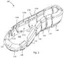
- FIG. 1shows a front isometric view of a shoe, according to some embodiments
- FIG. 2shows a back isometric view of a shoe, according to some embodiments
- FIG. 3shows a front planar view of a shoe, according to some embodiments
- FIG. 4shows a back planar view of a shoe, according to some embodiments
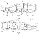
- FIG. 5shows a left planar view of a shoe, according to some embodiments.
- FIG. 6shows a right planar view of a shoe, according to some embodiments.
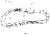
- FIG. 7shows a top planar view of a shoe, according to some embodiments.
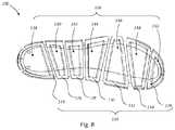
- FIG. 8shows a bottom planar view of a shoe, according to some embodiments.
- FIG. 9shows a longitudinal cross sectional view of a shoe, according to some embodiments.
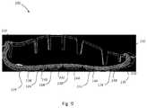
- FIG. 10shows a latitudinal cross sectional view of a shoe, according to some embodiments.
- the shoeis, essentially, a generally sole-shaped concave body, configured, on its own, to secure a wearer's foot inside it.
- this securingis achieved without any substantial structure to hold on to the foot from above.
- the concave bodyis comprised of a sole defined by an inwardly-biased circumferential wall.
- the wallhas one or more areas (hereinafter “foot securing areas”) where it is slightly inwardly-protruding, so as to provide a structurally-minimal but nonetheless effective means of securing the foot in the vertical axis.
- the shoeis structured with these foot securing areas being normally in an inwardly-protruding position, while still having a sufficient elasticity to enable them to be pushed outwardly by the foot when the shoe is put on.
- a person wishing to put on the shoemay position his or her foot over it and approximately in alignment with the sole shape of the shoe's body, and then simply push down the foot into the shoe.
- the circumferential wall of the shoeis engaged by the descending foot, its foot securing areas are pushed outwards, essentially expanding the circumferential wall and allowing the foot to enter the concave body of the shoe.
- the areasstart to return to their normal, inwardly-protruding position.
- the foot securing areasfinally reach their normal, inwardly-protruding position approximately when the foot is fully down the concave body of the shoe.
- the normally inwardly-protruding foot securing areasprevent the shoe from falling off the foot. Still, the elasticity of these foot securing areas allows for voluntary removal of the shoe, by application for force stronger than the typical downwards force exerted on the shoe naturally when walking. The degree of elasticity of these foot securing areas is carefully designed to this end.
- FIGS. 1-2show isometric views of an exemplary topless shoe (hereinafter “shoe”) 100 from the front and back, respectively.
- FIGS. 3-8show planar views of shoe 100 from the front, back, left, right, top and bottom, respectively, as well as to FIGS. 9-10 which show longitudinal (A) and latitudinal (B) cross-sections of the shoe, respectively.
- the figuresdepict a right shoe, but are naturally intended to apply also to a left shoe, mutatis mutandis.
- shoe 100may include three layers: a first layer 102 , e.g., serving as an insole, a second layer 104 , e.g., serving as a midsole, and a third layer 106 , e.g., serving as an outsole.
- a shoemay include only a single layer, while having a shape similar to that of the embodiment of the figures.
- a shoemay include two layers, while having a shape similar to that of the embodiment of the figures.
- a shoemay include four or more layers, while a shape similar to that of the embodiment of the figures.
- the term “sole”will be used to refer to all of these layers collectively.
- Those of skill in the artwill recognize, based on the former and following discussions, that all of the aforementioned, non-showed embodiments have multiple configurational aspects in common, despite being structured with a different number of layers and/or parts.
- Exemplary aspectsare the one or more foot securing areas which only minimally protrude inwardly. Such aspects endow these embodiments with advantageous qualities, such as the ability to secure a foot without any substantial structure to hold on to the foot from above, as discussed.
- the first layer 102may have a generally sole-shaped concave body, made of at least a sole-shaped part (or “surface”) 106 and an inwardly-biased circumferential wall 108 which defines the concave body.
- the wall 108may be divided, up to at least a portion of its height, into tabs, such as tabs 112 a - c , defining a plurality of vertical slots therebetween.
- Sole-shaped part 106 and rim 108may be unitarily formed, such as by injection molding, or be two separate parts attached together.
- the wall 108may be structured as a circumferential wall encompassing sole-shaped part 106 .
- the wall 108is intended, inter alia, to provide lateral support to the foot, somewhat similar to a welt of a conventional shoe. However, in contrast to many conventional shoes, the wall 108 is additionally configured, advantageously, to secure the foot vertically, without the need for substantial structures such as straps or strings that cover parts of the foot from above. This may be achieved by virtue of one or more foot securing areas, such as a representative foot securing area 110 a , shown encircled in FIG. 1 for demonstration reasons.
- Foot securing area 110 ais, essentially, an inwardly-protruding member of tab 112 a ; the wall 108 may be divided, across at least a portion of its height, into multiple tabs, such as tabs 112 a - c and the like.
- the sides of the footmay snugly fit into these lower areas of the tabs and at the same time be secured from above using the inwardly-protrusion of the foot securing areas.
- Foot securing areas of a shoesuch as shoe 100
- the degree of securingis usually a factor of the circumferential portion occupied by foot securing areas, versus the amount of inwardly protrusion of these areas. Generally, the more protruding these areas are, the less of them is required, and vice versa.
- the foot securing areas 110 a - cin accordance with some embodiments, may inwardly protruding to a only a minimal degree, i.e., such that the shoe 100 is essentially “topless”, and therefore extend along a substantial portion of the shoe's circumference, as discussed above.
- the shoe 100is open over a majority of the area above the sole thereof, for example as defined by the first layer 102 , i.e., an upper edge of the wall 108 at an uppermost edge of the shoe defines an opening which is formed substantially similar to the sole, e.g., being of similar proportions, size, and/or shape thereof.
- the openingmay be formed such that it is not exactly similar to the insole, for example owing to inwardly-projecting foot-securing areas 110 a - c , frontal parts 122 (discussed below) which function as a toe protector, etc., which still falling within the scope of being formed substantially similar to the sole.
- the openingmay be disposed above the sole, for example such that is lies substantially in registration therewith (i.e., wherein corresponding parts of its shape are disposed above analogous parts of the shape of the sole).
- the cross section in FIG. 10shows two points: a innermost point 114 of foot securing area 112 c , and an outermost point 116 of a lower area of tab 112 c (which may simply be referred to as the outermost point of the tab).
- a vertical-axis differential Dis marked between a vertical axis 114 a on which innermost point 114 resides, and between a vertical axis 116 a on which outermost point 116 resides.
- Dmay have different measurements at different circumferential areas of the wall 108 , to fit the foot's anatomy. This may both enhance the comfort of shoe 100 to its wearer, and enhance the shoe's securing of the foot.
- frontal parts of the footsuch as its dorsal surface, which are farther away from the foot's connection to the leg, may require securing using a larger D since they have a substantial lateral curvature.
- posterior parts of the footsuch as around the heel bone, may generally require securing using a smaller D; in some persons, however, parts surrounding the heel bone may sometimes lack a substantial lateral curvature, so that D may be very small or even zero.
- some areas of the wallmay extend higher up than others, to match the natural curvature of the foot's sides.
- Dmay measure between approximately 0.1-3 centimeters, depending on the foot part, as discussed above. In some other embodiments, D may measure between approximately 0.1-2 cm, 0.2-2 cm, 0.3-2 cm, 0.4-2 cm, 0.5-2 cm, 0.6-2 cm, 0.7-2 cm, 0.8-2 cm, 0.9-2 cm, 1-2 cm, 1.1-2 cm, 1.2-2 cm, 1.3-2 cm, 1.4-2 cm, 1.5-2 cm, 1.6-2 cm, 1.7-2 cm, 1.8-2 cm or 1.9-2 cm, for example depending on the foot part, the shoe size and/or the like. In further embodiments, D may exceed the aforementioned measurements.
- tabs 112 a - cmay purposely weaken the wall 108 structurally, so it may be conveniently pushed outwards by the foot when shoe 100 is put on.
- the first layer and/or the second layermay necessitate more tabs, while little or no tabs may be needed when more elastic materials are used—since the material elasticity, on its own, may be sufficient to allow the wall to widen to receive the foot.
- D and the rigidity/elasticity of the materialshave been carefully chosen and correlated in order to provide a functionally-beneficial tradeoff between a size of a top structure of shoe 100 , which is desired to be minimal, and the ability of such structure to secure the foot sufficiently.
- the second layer 104may be attached to the first layer 102 externally, such as by glue, melting and/or the like, and the interface between the two may follow the same (or a similar) curvature and shape along a substantial part of their area or even its entirety.
- first layer 102applies, mutatis mutandis, to the second layer 104 .
- similarly-shaped elements of the second layer 104shall be referred to using the same terminology of their respective elements in of the first layer 102 .
- functions of the first layer and the second layermay be materialized using a single layer serving both purposes, as discussed above.
- the first layer plus the second layer structureis adopted in order to combine comfort characteristics of the first layer 102 with more technical-functional characteristics of the second layer 104 .
- the structure of the second layer 104may depart from that of the first layer 102 in some parts thereof.
- One of the differences between the first layer 102 and the second layer 104may be, for example, their manufacturing from different materials.
- the first layer 102which comes in contact with the wearer's foot, may be made of a comfortable, soft and/or antimicrobial material(s)
- the second layer 104may be made of a more rigid material(s).
- the first layer 102may be made at least partially of one or more of silicone, polyethylene foam, another polymeric material, a non-polymeric material or any combination thereof.
- the thickness of the first layer 102 or parts thereofmay be in the range of 0.2 cm to 1.5 cm. In other embodiments, the thickness of the first layer 102 or parts thereof may be higher than 1.5 cm.
- the second layer 104may be made, for instance, at least partially of one or more of acrylonitrile butadiene styrene (ABS), another polymeric material, a non-polymeric material or any combination thereof.
- ABSacrylonitrile butadiene styrene
- the thickness of the second layer 104 or parts thereofmay be in the range of 0.2 cm to 1.5 cm. In other embodiments, the thickness of the second layer 104 or parts thereof may be higher than 1.5 cm.
- first layer 102 and the second layer 104may differ in the configuration of a top area of their walls.
- tab 110 c (and optionally other tabs) of the first layer 102may include a top area 118 c above foot securing area 112 c .
- Top area 118 cextends between innermost point 114 and an edge 118 , wherein the edge is disposed outwardly relative to innermost point 114 .
- the wall 108essentially becomes wider above innermost point 114 . This widening allows for easy entry of the foot into shoe 100 .
- tab 112 cis pushed outwards.
- edge 118is vertically-aligned, exactly or approximately, with outermost point 116 . Since the location of outermost point 116 is set to accommodate the foot's width, edge 118 has to be positioned at least on the same vertical axis as the outermost point, if not farther outwardly, in order for it to be wide enough to receive the foot.
- the division of the wall 108 of the first layer 102 into tabsdoes not necessarily correspond to a similar division of the second layer 104 .
- two or more adjacent tabs of the first layer 102may extend over a single tab of the second layer 104 , or vice versa.
- the structural weakening of shoe 100 using tab divisionmay be performed in only part of the layers of the shoe, and only in certain area(s).
- top area 120 cdoes not, in some embodiments, need to come in contact with the foot when shoe 100 is put on. Therefore, top area 120 c may be structured in such a way that it just supports top area 118 c of inner sole 102 . Top area 120 c may be structured, for example, as an outwards-curling part, which reinforces top area 118 c from outside.
- a sole-shaped part 106 of the first layer 102 , and that of the second layer 104may have different thicknesses across different parts thereof, in order to match the natural curvature of the foot's plantar surface. For example, greater thickness may be provided beneath the arches of the foot, and lower thickness may be disposed beneath the heel bone and the forefoot.
- a frontal part of shoe 100which is generally referenced as 122 , optionally lacks foot securing areas. Instead, frontal part 122 may be shaped as a toe protector, covering the toes or a part thereof. Frontal part 122 is optionally made of an extension of the first layer 102 . Since the toes are flexible, as opposed to other parts of the foot, a foot securing area in front of the toes is usually inefficient—the toes can easily escape it. Therefore, toe protection may be provided by frontal part 122 , or, in other embodiments (not shown), a frontal part of a shoe may lack such a cover altogether. Even if a cover exists, it may be structured and positioned such that there is a vertical gap between it and the toes when the shoe is worn; namely, it may not serve to secure the foot in place.
- a further difference between the first layer 102 and the second layer 104may be, for example, the extension of tabs of the second layer further down from tabs 112 a - c of the first layer.
- FIG. 8shows shoe 100 from a bottom view.
- the second layer 104is actually made up of a plurality of separate U-shaped elements, such as elements 124 - 136 , wherein the walls of the U-shape are the inwardly-biased circumferential wall of the second layer, and the bottom of the U-shape is the sole-shaped part of the second layer.
- At least the bottoms of at least some of the U-shaped elements of the second layer 104are separated and attached to the first layer 102 in such locations, that the spaces formed between the elements match the dynamics of the foot when walking.
- Thisas opposed to many conventional shoes in which the soles are only minimally-flexible and usually have the same degree of flexibility along their areas.
- shoe 100in general gives its wearer a feeling close to the feeling of walking barefoot. The natural, dynamic motion of different parts of the foot is only minimally affected due to the separation.
- the third layer 106may include pieces, such as pieces 138 - 150 , attached to elements 124 - 136 , respectively, externally.
- the third layer 106may be made of a highly-durable material, allowing it to last throughout prolonged use.
- a suitable materialis high-density polyurethane, but other materials are possible as well.
- the shoemay be provided without the third layer, and a the second layer may be made of a material(s) suitable both for supporting the first layer and durably interfacing with the ground.
- the shoe 100may comprise only the first layer 102 , as described above, without the second or third layers 104 , 106 . It may be made from any suitable material, for example a polymer or mix thereof having both thermoplastic and elastomeric properties such as thermoplastic elastomers or rubbers, from thermoplastic polyurethane, etc.
Landscapes
- Chemical & Material Sciences (AREA)
- Engineering & Computer Science (AREA)
- Materials Engineering (AREA)
- Footwear And Its Accessory, Manufacturing Method And Apparatuses (AREA)
Abstract
Description
Claims (14)
Priority Applications (1)
| Application Number | Priority Date | Filing Date | Title |
|---|---|---|---|
| US15/693,678US10765167B2 (en) | 2011-10-31 | 2017-09-01 | Topless shoe |
Applications Claiming Priority (4)
| Application Number | Priority Date | Filing Date | Title |
|---|---|---|---|
| US201161553401P | 2011-10-31 | 2011-10-31 | |
| PCT/IB2012/055231WO2013064925A1 (en) | 2011-10-31 | 2012-09-30 | Topless shoe |
| US201414355370A | 2014-04-30 | 2014-04-30 | |
| US15/693,678US10765167B2 (en) | 2011-10-31 | 2017-09-01 | Topless shoe |
Related Parent Applications (2)
| Application Number | Title | Priority Date | Filing Date |
|---|---|---|---|
| PCT/IB2012/055231Continuation-In-PartWO2013064925A1 (en) | 2011-10-31 | 2012-09-30 | Topless shoe |
| US14/355,370Continuation-In-PartUS20140305006A1 (en) | 2011-10-31 | 2012-09-30 | Topless shoe |
Publications (2)
| Publication Number | Publication Date |
|---|---|
| US20170360141A1 US20170360141A1 (en) | 2017-12-21 |
| US10765167B2true US10765167B2 (en) | 2020-09-08 |
Family
ID=60660963
Family Applications (1)
| Application Number | Title | Priority Date | Filing Date |
|---|---|---|---|
| US15/693,678Active - ReinstatedUS10765167B2 (en) | 2011-10-31 | 2017-09-01 | Topless shoe |
Country Status (1)
| Country | Link |
|---|---|
| US (1) | US10765167B2 (en) |
Cited By (11)
| Publication number | Priority date | Publication date | Assignee | Title |
|---|---|---|---|---|
| USD910291S1 (en)* | 2020-09-01 | 2021-02-16 | Keekoo Inc | Shoe |
| US20220287406A1 (en)* | 2020-11-20 | 2022-09-15 | Fast Ip, Llc | Rapid-entry footwear having a split back |
| US11918071B2 (en) | 2019-01-07 | 2024-03-05 | Fast Ip, Llc | Rapid-entry footwear having a compressible lattice structure |
| US11992092B2 (en) | 2016-04-22 | 2024-05-28 | Fast Ip, Llc | Rapid-entry footwear with rebounding fit system |
| US12022916B2 (en) | 2018-06-28 | 2024-07-02 | Fast Ip, Llc | Rapid-entry footwear having an actuator arm |
| US12048347B2 (en) | 2019-09-03 | 2024-07-30 | Fast Ip, Llc | Rapid-entry footwear having a pocket for a compressed medium |
| US12201180B2 (en) | 2020-01-28 | 2025-01-21 | Fast Ip, Llc | Rapid-entry footwear having rotatable straps |
| US12268272B2 (en) | 2020-10-13 | 2025-04-08 | Fast Ip, Llc | Rapid-entry footwear having a rotating rear portion and a fulcrum |
| US12274325B2 (en) | 2019-07-29 | 2025-04-15 | Fast Ip, Llc | Rapid-entry footwear having a stabilizer and an elastic element |
| US12364310B2 (en) | 2019-02-26 | 2025-07-22 | Fast Ip, Llc | Rapid-entry footwear having a heel arm and a resilient member |
| US12414609B2 (en) | 2021-03-24 | 2025-09-16 | Fast Ip, Llc | Rapid-entry footwear having a rotating tongue |
Families Citing this family (30)
| Publication number | Priority date | Publication date | Assignee | Title |
|---|---|---|---|---|
| US10624418B2 (en)* | 2016-01-25 | 2020-04-21 | Cole Haan Llc | Shoe having features for increased flexibility |
| USD895949S1 (en)* | 2018-12-07 | 2020-09-15 | Reebok International Limited | Shoe |
| USD1041852S1 (en) | 2019-04-26 | 2024-09-17 | Nike, Inc. | Shoe |
| USD1010300S1 (en) | 2019-04-26 | 2024-01-09 | Nike, Inc. | Shoe |
| USD900450S1 (en)* | 2019-04-26 | 2020-11-03 | Nike, Inc. | Shoe |
| USD903254S1 (en) | 2019-05-13 | 2020-12-01 | Reebok International Limited | Sole |
| USD899743S1 (en)* | 2019-05-14 | 2020-10-27 | Nike, Inc. | Shoe |
| USD900442S1 (en)* | 2019-05-14 | 2020-11-03 | Nike, Inc. | Shoe |
| US11490680B2 (en) | 2019-09-09 | 2022-11-08 | Fast Ip, Llc | Rapid-entry footwear having an arm for expanding an opening |
| USD925881S1 (en)* | 2019-11-27 | 2021-07-27 | Cole Haan Llc | Shoe sole |
| USD925879S1 (en)* | 2019-11-27 | 2021-07-27 | Cole Haan Llc | Shoe sole |
| USD932149S1 (en)* | 2019-11-27 | 2021-10-05 | Cole Haan Llc | Shoe sole |
| USD932169S1 (en)* | 2019-11-27 | 2021-10-05 | Cole Haan Llc | Shoe sole |
| USD925882S1 (en)* | 2019-11-27 | 2021-07-27 | Cole Haan Llc | Shoe sole |
| USD925885S1 (en)* | 2019-11-27 | 2021-07-27 | Cole Haan Llc | Shoe sole |
| USD925880S1 (en)* | 2019-11-27 | 2021-07-27 | Cole Haan Llc | Shoe sole |
| USD925883S1 (en)* | 2019-11-27 | 2021-07-27 | Cole Haan Llc | Shoe sole |
| USD925884S1 (en)* | 2019-11-27 | 2021-07-27 | Cole Haan Llc | Shoe sole |
| USD959802S1 (en)* | 2019-12-09 | 2022-08-09 | Airwair International Ltd. | Footwear |
| EP3838051A1 (en)* | 2019-12-20 | 2021-06-23 | Ecco Sko A/S | An article of footwear |
| EP3838050A1 (en)* | 2019-12-20 | 2021-06-23 | Ecco Sko A/S | An article of footwear |
| US11399590B2 (en)* | 2020-02-21 | 2022-08-02 | Nike, Inc. | Sole structure for article of footwear |
| USD933342S1 (en)* | 2020-04-04 | 2021-10-19 | Ecco Sko A/S | Footwear |
| WO2021234557A2 (en)* | 2020-05-18 | 2021-11-25 | Mittal Satyajit | Improved expandable shoe capable to grow with a wearer/user's feet for more than three sizes |
| USD995074S1 (en)* | 2020-07-09 | 2023-08-15 | Ecco Sko A/S | Footwear |
| USD928481S1 (en)* | 2020-09-03 | 2021-08-24 | Skechers U.S.A., Inc. Ii | Shoe midsole periphery |
| USD923309S1 (en)* | 2020-09-03 | 2021-06-29 | Skechers U.S.A., Inc. Ii | Shoe outsole bottom |
| AU2022221720A1 (en) | 2021-02-17 | 2023-07-27 | Fast Ip, Llc | Rapid-entry footwear having a transforming footbed |
| GB2607093B (en)* | 2021-05-28 | 2024-05-01 | William Fredrick Dean Martin | Footwear |
| USD1052865S1 (en) | 2022-10-04 | 2024-12-03 | Reebok International Limited | Shoe |
Citations (19)
| Publication number | Priority date | Publication date | Assignee | Title |
|---|---|---|---|---|
| US1811781A (en) | 1930-03-26 | 1931-06-23 | Eugene R Degge | Overshoe |
| US2677201A (en) | 1950-07-06 | 1954-05-04 | Lyon George Albert | Shoe of thin gauge sheet metal |
| US2693039A (en)* | 1953-01-26 | 1954-11-02 | Raymond R Balut | Quarter construction for slippers |
| GB1245975A (en) | 1968-04-02 | 1971-09-15 | Morris Goldschmidt | Clip-on shoe or sandal |
| US4542598A (en) | 1983-01-10 | 1985-09-24 | Colgate Palmolive Company | Athletic type shoe for tennis and other court games |
| US4779360A (en) | 1987-06-08 | 1988-10-25 | Bible George R | Shoe attachment to reduce inner and outer skidding |
| CA2079929A1 (en) | 1991-10-07 | 1993-04-08 | Renzo Giaconi | Method for the forming of open footwear, and footwear thus constituted |
| US5315767A (en) | 1989-09-07 | 1994-05-31 | Bradbury Frank M | Shoe sole saver |
| US5682685A (en) | 1995-10-12 | 1997-11-04 | Ballet Makers Inc. | Dance shoe sole |
| US20010005947A1 (en) | 1999-12-30 | 2001-07-05 | Luca Sordi | Shoe with a sole comprising a forefoot part divided into at least two elements |
| US20020078591A1 (en) | 2000-12-27 | 2002-06-27 | Ballet Makers, Inc. | Dance shoe with tri-split |
| WO2003001938A1 (en) | 2001-06-29 | 2003-01-09 | Noam Bernstein | Side entry footwear |
| USD475180S1 (en) | 2002-03-06 | 2003-06-03 | Pillows For Pointes, Inc. | Irish ghillie dance shoe |
| US20040098881A1 (en) | 2002-11-27 | 2004-05-27 | Bacchiega Flavio | Shoe structure |
| US20050066543A1 (en) | 2003-09-25 | 2005-03-31 | Rosen Glenn M. | Shoe cover |
| US20060288611A1 (en) | 2005-06-27 | 2006-12-28 | Hogan Patrick J | Suspended orthotic shoe and methods of making same |
| USD558964S1 (en) | 2005-12-23 | 2008-01-08 | Ecco Sko A/S | Shoe sole |
| US20080184592A1 (en) | 2005-09-15 | 2008-08-07 | Alfred Cloutier Ltee | Adaptable Shoe Cover |
| US20090288314A1 (en) | 2008-05-20 | 2009-11-26 | Richard Keith Kay | Cover for cleated shoes |
- 2017
- 2017-09-01USUS15/693,678patent/US10765167B2/enactiveActive - Reinstated
Patent Citations (23)
| Publication number | Priority date | Publication date | Assignee | Title |
|---|---|---|---|---|
| US1811781A (en) | 1930-03-26 | 1931-06-23 | Eugene R Degge | Overshoe |
| US2677201A (en) | 1950-07-06 | 1954-05-04 | Lyon George Albert | Shoe of thin gauge sheet metal |
| US2693039A (en)* | 1953-01-26 | 1954-11-02 | Raymond R Balut | Quarter construction for slippers |
| GB1245975A (en) | 1968-04-02 | 1971-09-15 | Morris Goldschmidt | Clip-on shoe or sandal |
| US4542598A (en) | 1983-01-10 | 1985-09-24 | Colgate Palmolive Company | Athletic type shoe for tennis and other court games |
| US4779360A (en) | 1987-06-08 | 1988-10-25 | Bible George R | Shoe attachment to reduce inner and outer skidding |
| US5315767A (en) | 1989-09-07 | 1994-05-31 | Bradbury Frank M | Shoe sole saver |
| CA2079929A1 (en) | 1991-10-07 | 1993-04-08 | Renzo Giaconi | Method for the forming of open footwear, and footwear thus constituted |
| US5682685A (en) | 1995-10-12 | 1997-11-04 | Ballet Makers Inc. | Dance shoe sole |
| US6634121B2 (en) | 1999-12-30 | 2003-10-21 | Freddy S.P.A. | Shoe with a sole comprising a forefoot part divided into at least two elements |
| US20010005947A1 (en) | 1999-12-30 | 2001-07-05 | Luca Sordi | Shoe with a sole comprising a forefoot part divided into at least two elements |
| US20020078591A1 (en) | 2000-12-27 | 2002-06-27 | Ballet Makers, Inc. | Dance shoe with tri-split |
| US6578288B2 (en)* | 2001-06-29 | 2003-06-17 | Noam Bernstein | Side entry footwear |
| WO2003001938A1 (en) | 2001-06-29 | 2003-01-09 | Noam Bernstein | Side entry footwear |
| USD475180S1 (en) | 2002-03-06 | 2003-06-03 | Pillows For Pointes, Inc. | Irish ghillie dance shoe |
| US20040098881A1 (en) | 2002-11-27 | 2004-05-27 | Bacchiega Flavio | Shoe structure |
| US20050066543A1 (en) | 2003-09-25 | 2005-03-31 | Rosen Glenn M. | Shoe cover |
| US6988328B2 (en) | 2003-09-25 | 2006-01-24 | Rosen Glenn M | Shoe cover |
| US20060288611A1 (en) | 2005-06-27 | 2006-12-28 | Hogan Patrick J | Suspended orthotic shoe and methods of making same |
| US20080184592A1 (en) | 2005-09-15 | 2008-08-07 | Alfred Cloutier Ltee | Adaptable Shoe Cover |
| US8474153B2 (en) | 2005-09-15 | 2013-07-02 | Alfred Cloutier Ltée | Adaptable shoe cover |
| USD558964S1 (en) | 2005-12-23 | 2008-01-08 | Ecco Sko A/S | Shoe sole |
| US20090288314A1 (en) | 2008-05-20 | 2009-11-26 | Richard Keith Kay | Cover for cleated shoes |
Non-Patent Citations (3)
| Title |
|---|
| "ToplessShoes Concept by Zhao Xiaoliang, Han Like, Liu Peng, Meng Qingbao, Ren Mingjun, Yang Xiao, Chen Xuan & Lin Lin", TechCracksConcept Design Gallery, last modified on Mar. 1, 2012. |
| The International Search Report (PCT/ISA/210) for International Application No. PCT/IB2012/055231, 3 pages, dated Feb. 25, 2013. |
| The Supplementary European Search Report, 2 pages, search completed on Feb. 16, 2016. |
Cited By (14)
| Publication number | Priority date | Publication date | Assignee | Title |
|---|---|---|---|---|
| US12102178B2 (en) | 2016-04-22 | 2024-10-01 | Fast Ip, Llc | Rapid-entry footwear with rebounding fit system |
| US12207702B2 (en) | 2016-04-22 | 2025-01-28 | Fast Ip, Llc | Rapid-entry footwear with rebounding fit system |
| US11992092B2 (en) | 2016-04-22 | 2024-05-28 | Fast Ip, Llc | Rapid-entry footwear with rebounding fit system |
| US12022916B2 (en) | 2018-06-28 | 2024-07-02 | Fast Ip, Llc | Rapid-entry footwear having an actuator arm |
| US11918071B2 (en) | 2019-01-07 | 2024-03-05 | Fast Ip, Llc | Rapid-entry footwear having a compressible lattice structure |
| US12364310B2 (en) | 2019-02-26 | 2025-07-22 | Fast Ip, Llc | Rapid-entry footwear having a heel arm and a resilient member |
| US12274325B2 (en) | 2019-07-29 | 2025-04-15 | Fast Ip, Llc | Rapid-entry footwear having a stabilizer and an elastic element |
| US12048347B2 (en) | 2019-09-03 | 2024-07-30 | Fast Ip, Llc | Rapid-entry footwear having a pocket for a compressed medium |
| US12201180B2 (en) | 2020-01-28 | 2025-01-21 | Fast Ip, Llc | Rapid-entry footwear having rotatable straps |
| USD910291S1 (en)* | 2020-09-01 | 2021-02-16 | Keekoo Inc | Shoe |
| US12268272B2 (en) | 2020-10-13 | 2025-04-08 | Fast Ip, Llc | Rapid-entry footwear having a rotating rear portion and a fulcrum |
| US20220287406A1 (en)* | 2020-11-20 | 2022-09-15 | Fast Ip, Llc | Rapid-entry footwear having a split back |
| US12426666B2 (en)* | 2020-11-20 | 2025-09-30 | Fast Ip, Llc | Rapid-entry footwear having a split back |
| US12414609B2 (en) | 2021-03-24 | 2025-09-16 | Fast Ip, Llc | Rapid-entry footwear having a rotating tongue |
Also Published As
| Publication number | Publication date |
|---|---|
| US20170360141A1 (en) | 2017-12-21 |
Similar Documents
| Publication | Publication Date | Title |
|---|---|---|
| US10765167B2 (en) | Topless shoe | |
| EP2804501B1 (en) | Topless shoe | |
| US12042004B2 (en) | Articles of footwear transitional between a foot insertion or removal configuration and a foot supporting configuration | |
| EP3616546B1 (en) | Comfort in motion footwear | |
| US9504293B2 (en) | Outsole with extendable traction elements | |
| US8215036B2 (en) | Removable heel bucket | |
| EP2395868B1 (en) | Stability and comfort system for an article of footwear | |
| EP2906066B1 (en) | Ultralightweight adaptive heel member | |
| CN108354264B (en) | Article of footwear with sole structure | |
| US8001704B2 (en) | Footwear with a foot stabilizer | |
| US7685742B2 (en) | Impact-attenuation systems for articles of footwear and other foot-receiving devices | |
| US9468251B2 (en) | Sole assembly including a central support structure for an article of footwear | |
| US20130255106A1 (en) | Assembled footwear | |
| WO1999039601A1 (en) | Shoe sole | |
| EP3110276B1 (en) | Footwear system with removable inserts | |
| CN111741693A (en) | Insole, insole for high-heeled shoes and manufacturing and using methods of insole and insole | |
| EP3881706A1 (en) | Sock lining for footwear, etc | |
| JP3178435U (en) | Insoles | |
| HK1093664A (en) | Footwear sole |
Legal Events
| Date | Code | Title | Description |
|---|---|---|---|
| FEPP | Fee payment procedure | Free format text:ENTITY STATUS SET TO UNDISCOUNTED (ORIGINAL EVENT CODE: BIG.); ENTITY STATUS OF PATENT OWNER: MICROENTITY | |
| FEPP | Fee payment procedure | Free format text:ENTITY STATUS SET TO MICRO (ORIGINAL EVENT CODE: MICR); ENTITY STATUS OF PATENT OWNER: MICROENTITY Free format text:ENTITY STATUS SET TO SMALL (ORIGINAL EVENT CODE: SMAL); ENTITY STATUS OF PATENT OWNER: MICROENTITY | |
| AS | Assignment | Owner name:AZOULAY, YEHUDA, ISRAEL Free format text:ASSIGNMENT OF ASSIGNORS INTEREST;ASSIGNOR:GROSSMAN, OLGA;REEL/FRAME:044329/0185 Effective date:20171116 | |
| STPP | Information on status: patent application and granting procedure in general | Free format text:RESPONSE TO NON-FINAL OFFICE ACTION ENTERED AND FORWARDED TO EXAMINER | |
| STPP | Information on status: patent application and granting procedure in general | Free format text:FINAL REJECTION MAILED | |
| STPP | Information on status: patent application and granting procedure in general | Free format text:DOCKETED NEW CASE - READY FOR EXAMINATION | |
| STPP | Information on status: patent application and granting procedure in general | Free format text:NON FINAL ACTION MAILED | |
| STPP | Information on status: patent application and granting procedure in general | Free format text:RESPONSE TO NON-FINAL OFFICE ACTION ENTERED AND FORWARDED TO EXAMINER | |
| ZAAA | Notice of allowance and fees due | Free format text:ORIGINAL CODE: NOA | |
| ZAAB | Notice of allowance mailed | Free format text:ORIGINAL CODE: MN/=. | |
| FEPP | Fee payment procedure | Free format text:ENTITY STATUS SET TO MICRO (ORIGINAL EVENT CODE: MICR); ENTITY STATUS OF PATENT OWNER: MICROENTITY | |
| STCF | Information on status: patent grant | Free format text:PATENTED CASE | |
| FEPP | Fee payment procedure | Free format text:MAINTENANCE FEE REMINDER MAILED (ORIGINAL EVENT CODE: REM.); ENTITY STATUS OF PATENT OWNER: MICROENTITY | |
| LAPS | Lapse for failure to pay maintenance fees | Free format text:PATENT EXPIRED FOR FAILURE TO PAY MAINTENANCE FEES (ORIGINAL EVENT CODE: EXP.); ENTITY STATUS OF PATENT OWNER: MICROENTITY | |
| STCH | Information on status: patent discontinuation | Free format text:PATENT EXPIRED DUE TO NONPAYMENT OF MAINTENANCE FEES UNDER 37 CFR 1.362 | |
| FP | Lapsed due to failure to pay maintenance fee | Effective date:20240908 | |
| PRDP | Patent reinstated due to the acceptance of a late maintenance fee | Effective date:20250501 | |
| FEPP | Fee payment procedure | Free format text:ENTITY STATUS SET TO SMALL (ORIGINAL EVENT CODE: SMAL); ENTITY STATUS OF PATENT OWNER: MICROENTITY Free format text:PETITION RELATED TO MAINTENANCE FEES FILED (ORIGINAL EVENT CODE: PMFP); ENTITY STATUS OF PATENT OWNER: MICROENTITY Free format text:PETITION RELATED TO MAINTENANCE FEES GRANTED (ORIGINAL EVENT CODE: PMFG); ENTITY STATUS OF PATENT OWNER: MICROENTITY Free format text:ENTITY STATUS SET TO MICRO (ORIGINAL EVENT CODE: MICR); ENTITY STATUS OF PATENT OWNER: MICROENTITY Free format text:SURCHARGE, PETITION TO ACCEPT PYMT AFTER EXP, UNINTENTIONAL (ORIGINAL EVENT CODE: M3558); ENTITY STATUS OF PATENT OWNER: MICROENTITY | |
| MAFP | Maintenance fee payment | Free format text:PAYMENT OF MAINTENANCE FEE, 4TH YEAR, MICRO ENTITY (ORIGINAL EVENT CODE: M3551); ENTITY STATUS OF PATENT OWNER: MICROENTITY Year of fee payment:4 | |
| STCF | Information on status: patent grant | Free format text:PATENTED CASE |