US10764747B2 - Key management for wireless communication system for communicating engine data - Google Patents
Key management for wireless communication system for communicating engine dataDownload PDFInfo
- Publication number
- US10764747B2 US10764747B2US15/632,488US201715632488AUS10764747B2US 10764747 B2US10764747 B2US 10764747B2US 201715632488 AUS201715632488 AUS 201715632488AUS 10764747 B2US10764747 B2US 10764747B2
- Authority
- US
- United States
- Prior art keywords
- destination server
- computing device
- remote computing
- key
- engine
- Prior art date
- Legal status (The legal status is an assumption and is not a legal conclusion. Google has not performed a legal analysis and makes no representation as to the accuracy of the status listed.)
- Active
Links
- 238000004891communicationMethods0.000titleclaimsdescription79
- 238000000034methodMethods0.000claimsabstractdescription31
- 238000012546transferMethods0.000claimsdescription26
- 230000004044responseEffects0.000claimsdescription7
- 230000000977initiatory effectEffects0.000claimsdescription4
- 239000000567combustion gasSubstances0.000description10
- 238000002485combustion reactionMethods0.000description6
- 238000010586diagramMethods0.000description6
- 239000007789gasSubstances0.000description6
- 239000000446fuelSubstances0.000description5
- 238000012423maintenanceMethods0.000description4
- 238000007726management methodMethods0.000description4
- 230000006399behaviorEffects0.000description3
- 230000008901benefitEffects0.000description3
- 230000001413cellular effectEffects0.000description3
- 238000012986modificationMethods0.000description3
- 230000004048modificationEffects0.000description3
- 230000008859changeEffects0.000description2
- 230000006870functionEffects0.000description2
- 230000007246mechanismEffects0.000description2
- 238000012545processingMethods0.000description2
- 230000001141propulsive effectEffects0.000description2
- 230000005540biological transmissionEffects0.000description1
- 239000004020conductorSubstances0.000description1
- 238000013500data storageMethods0.000description1
- 238000013461designMethods0.000description1
- 238000005538encapsulationMethods0.000description1
- 230000036541healthEffects0.000description1
- 238000012360testing methodMethods0.000description1
- 230000007704transitionEffects0.000description1
Images


Classifications
- H—ELECTRICITY
- H04—ELECTRIC COMMUNICATION TECHNIQUE
- H04L—TRANSMISSION OF DIGITAL INFORMATION, e.g. TELEGRAPHIC COMMUNICATION
- H04L9/00—Cryptographic mechanisms or cryptographic arrangements for secret or secure communications; Network security protocols
- H04L9/08—Key distribution or management, e.g. generation, sharing or updating, of cryptographic keys or passwords
- H04L9/0816—Key establishment, i.e. cryptographic processes or cryptographic protocols whereby a shared secret becomes available to two or more parties, for subsequent use
- H04L9/0819—Key transport or distribution, i.e. key establishment techniques where one party creates or otherwise obtains a secret value, and securely transfers it to the other(s)
- H04L9/0825—Key transport or distribution, i.e. key establishment techniques where one party creates or otherwise obtains a secret value, and securely transfers it to the other(s) using asymmetric-key encryption or public key infrastructure [PKI], e.g. key signature or public key certificates
- H—ELECTRICITY
- H04—ELECTRIC COMMUNICATION TECHNIQUE
- H04L—TRANSMISSION OF DIGITAL INFORMATION, e.g. TELEGRAPHIC COMMUNICATION
- H04L9/00—Cryptographic mechanisms or cryptographic arrangements for secret or secure communications; Network security protocols
- H04L9/08—Key distribution or management, e.g. generation, sharing or updating, of cryptographic keys or passwords
- H04L9/0816—Key establishment, i.e. cryptographic processes or cryptographic protocols whereby a shared secret becomes available to two or more parties, for subsequent use
- H04L9/0819—Key transport or distribution, i.e. key establishment techniques where one party creates or otherwise obtains a secret value, and securely transfers it to the other(s)
- H04L9/0827—Key transport or distribution, i.e. key establishment techniques where one party creates or otherwise obtains a secret value, and securely transfers it to the other(s) involving distinctive intermediate devices or communication paths
- H—ELECTRICITY
- H04—ELECTRIC COMMUNICATION TECHNIQUE
- H04W—WIRELESS COMMUNICATION NETWORKS
- H04W12/00—Security arrangements; Authentication; Protecting privacy or anonymity
- H04W12/04—Key management, e.g. using generic bootstrapping architecture [GBA]
- H—ELECTRICITY
- H04—ELECTRIC COMMUNICATION TECHNIQUE
- H04W—WIRELESS COMMUNICATION NETWORKS
- H04W12/00—Security arrangements; Authentication; Protecting privacy or anonymity
- H04W12/04—Key management, e.g. using generic bootstrapping architecture [GBA]
- H04W12/041—Key generation or derivation
- H—ELECTRICITY
- H04—ELECTRIC COMMUNICATION TECHNIQUE
- H04L—TRANSMISSION OF DIGITAL INFORMATION, e.g. TELEGRAPHIC COMMUNICATION
- H04L2209/00—Additional information or applications relating to cryptographic mechanisms or cryptographic arrangements for secret or secure communication H04L9/00
- H04L2209/80—Wireless
- H—ELECTRICITY
- H04—ELECTRIC COMMUNICATION TECHNIQUE
- H04L—TRANSMISSION OF DIGITAL INFORMATION, e.g. TELEGRAPHIC COMMUNICATION
- H04L2209/00—Additional information or applications relating to cryptographic mechanisms or cryptographic arrangements for secret or secure communication H04L9/00
- H04L2209/84—Vehicles
- H—ELECTRICITY
- H04—ELECTRIC COMMUNICATION TECHNIQUE
- H04L—TRANSMISSION OF DIGITAL INFORMATION, e.g. TELEGRAPHIC COMMUNICATION
- H04L9/00—Cryptographic mechanisms or cryptographic arrangements for secret or secure communications; Network security protocols
- H04L9/08—Key distribution or management, e.g. generation, sharing or updating, of cryptographic keys or passwords
- H04L9/0861—Generation of secret information including derivation or calculation of cryptographic keys or passwords
Definitions
- the present subject matterrelates generally to aviation systems.
- An aerial vehiclecan include one or more engines for propulsion of the aerial vehicle.
- the one or more enginescan include and/or can be in communication with one or more electronic engine controllers (EECs).
- EECselectronic engine controllers
- the one or more EECscan record data related to the one or more engines. If the data resides on the EECs, then it can be difficult for a ground system to use the data. Automated engine data transfer replaces manual data retrieval and increases the availability of data at the ground system.
- the wireless communication unitcan include one or more memory devices.
- the wireless communication unitcan include one or more processors.
- the one or more processorscan be configured to generate a pair of keys, wherein one of the pair of keys is a private key, and wherein one of the pair of keys is a public key.
- the one or more processorscan be configured to transmit the public key to a first remote computing device, wherein the first remote computing device transmits the public key to a second remote computing device.
- the one or more processorscan be configured to receive a host key from the first remote computing device, wherein the first remote computing device received the host key from the second remote computing device.
- the one or more processorscan be configured to access the second remote computing device using the private key.
- the one or more processorscan be configured to verify a request from the second remote computing device using the host key.
- FIG. 1depicts an aerial vehicle according to example embodiments of the present disclosure
- FIG. 2depicts an engine according to example embodiments of the present disclosure
- FIG. 3depicts a wireless communication system according to example embodiments of the present disclosure
- FIG. 4depicts a flow diagram of an example method according to example embodiments of the present disclosure
- FIG. 5depicts a computing system for implementing one or more aspects according to example embodiments of the present disclosure.
- FIG. 6depicts a sequence diagram of an example method according to example embodiments of the present disclosure.
- Example aspects of the present disclosureare directed to methods and systems for recording and communicating engine data on an aerial vehicle.
- the aerial vehiclecan include one or more engines for operations, such as propulsion of the aerial vehicle.
- the one or more enginescan include and/or be in communication with one or more electronic engine controllers (EECs).
- EECselectronic engine controllers
- the one or more engines and/or the one or more EECscan include and/or can be in communication with one or more wireless communication units (WCUs).
- WCUswireless communication units
- the one or more EECscan record data related to the one or more engines and can communicate (e.g., transmit, send, push, etc.) the data to the one or more WCUs, where the WCUs can store the data in a memory.
- Each EECcan communicate the data to its own associated WCU.
- each EECcan communicate data to a single WCU located on the aerial vehicle.
- the one or more WCUscan communicate the data to a ground system over a wireless network, such as a cellular network.
- the WCUcan be adaptable for communication with the EEC via an interface.
- the interfacecan be a Telecommunications Industry Association (TIA) TIA-485 interface, an Ethernet interface, an Aeronautical Radio INC (ARINC) 664 interface, an RS-232 interface, etc.
- the WCUcan be adaptable for communication with the ground system via an antenna.
- the WCUcan transmit information received from the EEC to the ground system.
- the ground systemcan use the information received from the WCU to determine a status (e.g., state, health, etc.) of an engine associated with the WCU.
- the WCUcan be adaptable for communication with a portable maintenance access terminal (PMAT) for maintenance.
- PMATportable maintenance access terminal
- the WCUcan have a need for a pair of encryption keys.
- the WCUcan be new and need a first pair of encryption keys.
- a pair of encryption keys currently stored by the WCUcan expire.
- the WCUcan generate a pair of encryption keys.
- the pair of encryption keyscan include a public key and a private key.
- the WCUcan transmit (e.g., send, transfer, etc.) the public key to a secure key server.
- the secure key servercan be addressable by a fixed Internet Protocol (IP) address.
- IPInternet Protocol
- the WCUcan login to the secure key server with a login and/or a password.
- the secure key servercan receive one or more server host keys from one or more destination servers.
- the one or more destination serverscan communicate via Secure Shell (SSH) using the one or more server host keys and/or the pair of keys.
- SSHSecure Shell
- the one or more destination serverscan be addressable at one or more fixed IP addresses.
- the one or more destination serverscan be protected with a password.
- the WCUcan receive the one or more server host keys from the secure key server.
- the one or more destination serverscan receive the public key from the secure key server using a transfer protocol that uses SSH to encrypt messages, such as Secure File Transfer Protocol (SFTP), Secure Copy (SCP), etc.
- SFTPSecure File Transfer Protocol
- SCPSecure Copy
- the WCUcan transmit a Domain Name System (DNS) query to a DNS server.
- DNSDomain Name System
- the DNS servercan transmit a DNS response to the WCU.
- the WCUcan receive an IP address for a closest destination server of the one or more destination servers. A determination of the closest destination server can be made based on a provided cell location.
- the WCUcan access the closest destination server through a Secure Shell (SSH) tunnel with the private key.
- SSHSecure Shell
- the WCUcan use the server host key to verify the identity of the closest destination server.
- the WCUcan log into a closest destination file transfer protocol (FTP) server with a username and/or a password.
- FTPfile transfer protocol
- the WCUcan receive a Login acknowledgement from the closest destination server.
- the WCUcan initiate a bulk transfer of data to the closest destination server.
- the closest destination servercan forward the data to a database. In an embodiment, any data transmitted to any of the one or more destination servers can be forwarded to the database.
- the wireless communication unitcan include one or more memory devices.
- the wireless communication unitcan include one or more processors.
- the one or more processorscan be configured to generate a pair of keys, wherein one of the pair of keys is a private key, and wherein one of the pair of keys is a public key.
- the one or more processorscan be configured to transmit the public key to a first remote computing device, wherein the first remote computing device transmits the public key to a second remote computing device.
- the one or more processorscan be configured to receive a host key from the first remote computing device, wherein the first remote computing device received the host key from the second remote computing device.
- the one or more processorscan be configured to access the second remote computing device using the private key.
- the one or more processorscan be configured to verify a request from the second remote computing device using the host key.
- the wireless communication unitis associated with an engine. In an embodiment, the wireless communication unit is associated with an aerial vehicle. In an embodiment, the first remote computing device is associated with a ground system. In an embodiment, the second remote computing device is associated with a ground system. In an embodiment, the first remote computing device is a secure key server addressable by a fixed Internet Protocol address. In an embodiment, the second remote computing device is a destination server addressable by a fixed Internet Protocol address. In an embodiment, the one or more processors of the wireless communication unit are further configured to initiate a bulk transfer of data to the destination server. In an embodiment, the destination server forwards the transferred data to a third remote computing device. In an embodiment, the third remote computing device includes a data lake.
- the methodincludes generating, by one or more local computing devices configured to be located in a nacelle associated with an engine of an aerial vehicle, a pair of keys, wherein one of the pair of keys is a private key, and wherein one of the pair of keys is a public key.
- the methodincludes transmitting, by the one or more local computing devices, the public key to a first remote computing device, wherein the first remote computing device transmits the public key to a second remote computing device.
- the methodincludes receiving, by the one or more local computing devices, a host key from the first remote computing device, wherein the first remote computing device received the host key from the second remote computing device.
- the methodincludes accessing, by the one or more local computing devices, the second remote computing device using the private key.
- the methodincludes verifying, by the one or more local computing devices, a request from the second remote computing device using the host key.
- a wireless communication unitincludes the one or more local computing devices.
- the wireless communication unitis associated with an engine.
- the wireless communication unitis associated with an aerial vehicle.
- the first remote computing deviceis associated with a ground system.
- the second remote computing deviceis associated with a ground system.
- the first remote computing deviceis a secure key server addressable by a fixed Internet Protocol address.
- the second remote computing deviceis a destination server addressable by a fixed Internet Protocol address.
- the methodfurther includes initiating a bulk transfer of data to the destination server.
- the destination serverforwards the transferred data to a third remote computing device.
- the third remote computing deviceincludes a data lake.
- the systemcan include a wireless communication unit configured to be located in a nacelle associated with an engine of an aerial vehicle.
- the wireless communication unitcan include one or more memory devices.
- the wireless communication unitcan include one or more processors.
- the one or more processorscan be configured to generate a pair of keys, wherein one of the pair of keys is a private key, and wherein one of the pair of keys is a public key.
- the one or more processorscan be configured to transmit the public key to a first remote computing device, wherein the first remote computing device transmits the public key to a second remote computing device.
- the one or more processorscan be configured to receive a host key from the first remote computing device, wherein the first remote computing device received the host key from the second remote computing device.
- the one or more processorscan be configured to access the second remote computing device using the private key.
- the one or more processorscan be configured to verify a request from the second remote computing device using the host key.
- the wireless communication unitis associated with an engine. In an embodiment, the wireless communication unit is associated with an aerial vehicle. In an embodiment, the first remote computing device is associated with a ground system. In an embodiment, the second remote computing device is associated with a ground system. In an embodiment, the first remote computing device is a secure key server addressable by a fixed Internet Protocol address. In an embodiment, the second remote computing device is a destination server addressable by a fixed Internet Protocol address. In an embodiment, the one or more processors of the wireless communication unit are further configured to initiate a bulk transfer of data to the destination server. In an embodiment, the destination server forwards the transferred data to a third remote computing device. In an embodiment, the third remote computing device includes a data lake.
- the aerial vehicleincludes a wireless communication unit.
- the wireless communication unitcan include one or more memory devices.
- the wireless communication unitcan include one or more processors.
- the one or more processorscan be configured to generate a pair of keys, wherein one of the pair of keys is a private key, and wherein one of the pair of keys is a public key.
- the one or more processorscan be configured to transmit the public key to a first remote computing device, wherein the first remote computing device transmits the public key to a second remote computing device.
- the one or more processorscan be configured to receive a host key from the first remote computing device, wherein the first remote computing device received the host key from the second remote computing device.
- the one or more processorscan be configured to access the second remote computing device using the private key.
- the one or more processorscan be configured to verify a request from the second remote computing device using the host key.
- the wireless communication unitis associated with an engine.
- the first remote computing deviceis associated with a ground system.
- the second remote computing deviceis associated with a ground system.
- the first remote computing deviceis a secure key server addressable by a fixed Internet Protocol address.
- the second remote computing deviceis a destination server addressable by a fixed Internet Protocol address.
- the one or more processors of the wireless communication unitare further configured to initiate a bulk transfer of data to the destination server.
- the destination serverforwards the transferred data to a third remote computing device.
- the third remote computing deviceincludes a data lake.
- FIG. 1depicts a block diagram of an aerial vehicle 100 according to example embodiments of the present disclosure.
- the aerial vehicle 100can include one or more engines 102 .
- the one or more engines 102can cause operations, such as propulsion, of the aerial vehicle 100 .
- An engine 102can include a nacelle 50 for housing components.
- An engine 102can be a gas turbine engine.
- a gas turbine enginecan include a fan and a core arranged in flow communication with one another. Additionally, the core of the gas turbine engine generally includes, in serial flow order, a compressor section, a combustion section, a turbine section, and an exhaust section. In operation, air is provided from the fan to an inlet of the compressor section where one or more axial compressors progressively compress the air until it reaches the combustion section.
- Fuelis mixed with the compressed air and burned within the combustion section to provide combustion gases.
- the combustion gasesare routed from the combustion section to the turbine section.
- the flow of combustion gases through the turbine sectiondrives the turbine section and is then routed through the exhaust section, e.g., to atmosphere.
- the one or more engines 102can include and/or be in communication with one or more electronic engine controllers (EECs) 104 .
- the one or more engines 102 and/or the one or more EECs 104can include and/or be in communication with one or more wireless communication units (WCUs) 106 .
- the one or more EECs 104can record data related to the one or more engines 102 and communicate (e.g., transmit, send, push, etc.) the data to the one or more WCUs 106 .
- the one or more WCUs 106can communicate the data to a ground system, via, for instance, an antenna positioned and configured within the nacelle 50 .
- the one or more WCUs 106can be located within a nacelle 50 housing an engine 102 or another location on the aerial vehicle 100 .
- FIG. 2depicts an engine 102 according to example embodiments of the present disclosure.
- the engine 102can be one of the one or more engines 102 on the aerial vehicle 100 in FIG. 1 . More particularly, for the embodiment of FIG. 2 , the engine 102 is configured as a gas turbine engine, or rather as a high-bypass turbofan jet engine 102 , referred to herein as “turbofan engine 102 .”
- Turbofan engine 102a gas turbine engine, or rather as a high-bypass turbofan jet engine 102 , referred to herein as “turbofan engine 102 .”
- WCUscan be used in conjunction with other types of propulsion engines without deviating from the scope of the present disclosure, including engines associated with helicopters and propellers.
- the turbofan engine 102defines an axial direction A (extending parallel to a longitudinal centerline 13 provided for reference), a radial direction R, and a circumferential direction (not shown) extending about the axial direction A.
- the turbofanincludes a fan section 14 and a core turbine engine 16 disposed downstream from the fan section 14 .
- the exemplary core turbine engine 16 depictedgenerally includes a substantially tubular outer casing 18 that defines an annular inlet 20 .
- the outer casing 18encases and the core turbine engine 16 includes, in serial flow relationship, a compressor section including a booster or low pressure (LP) compressor 22 and a high pressure (HP) compressor 24 ; a combustion section 26 ; a turbine section including a high pressure (HP) turbine 28 and a low pressure (LP) turbine 30 ; and a jet exhaust nozzle section 32 .
- a high pressure (HP) shaft or spool 34drivingly connects the HP turbine 28 to the HP compressor 24 .
- a low pressure (LP) shaft or spool 36drivingly connects the LP turbine 30 to the LP compressor 22 .
- the LP shaft 36 and HP shaft 34are each rotary components, rotating about the axial direction A during operation of the turbofan engine 102 .
- the turbofan engineincludes a plurality of air bearings 80 attached to various structural components within the turbofan engine 102 .
- the bearings 80facilitate rotation of, e.g., the LP shaft 36 and HP shaft 34 and dampen vibrational energy imparted to bearings 80 during operation of the turbofan engine 102 .
- bearings 80are described and illustrated as being located generally at forward and aft ends of the respective LP shaft 36 and HP shaft 34 , the bearings 80 may additionally, or alternatively, be located at any desired location along the LP shaft 36 and HP shaft 34 including, but not limited to, central or mid-span regions of the shafts 34 , 36 , or other locations along shafts 34 , 36 where the use of conventional bearings 80 would present significant design challenges. Further, bearings 80 may be used in combination with conventional oil-lubricated bearings. For example, in one embodiment, conventional oil-lubricated bearings may be located at the ends of shafts 34 , 36 , and one or more bearings 80 may be located along central or mid-span regions of shafts 34 , 36 .
- the fan section 14includes a fan 38 having a plurality of fan blades 40 coupled to a disk 42 in a spaced apart manner. As depicted, the fan blades 40 extend outwardly from disk 42 generally along the radial direction R. Each fan blade 40 is rotatable relative to the disk 42 about a pitch axis P by virtue of the fan blades 40 being operatively coupled to a suitable pitch change mechanism 44 configured to collectively vary the pitch of the fan blades 40 in unison.
- the fan blades 40 , disk 42 , and pitch change mechanism 44are together rotatable about the longitudinal axis 13 by LP shaft 36 across a power gear box 46 .
- the power gear box 46includes a plurality of gears for adjusting the rotational speed of the fan 38 relative to the LP shaft 36 to a more efficient rotational fan speed. More particularly, the fan section includes a fan shaft rotatable by the LP shaft 36 across the power gearbox 46 . Accordingly, the fan shaft may also be considered a rotary component, and is similarly supported by one or more bearings.
- the disk 42is covered by a rotatable front hub 48 aerodynamically contoured to promote an airflow through the plurality of fan blades 40 .
- the exemplary fan section 14includes an annular fan casing or outer nacelle 50 that circumferentially surrounds the fan 38 and/or at least a portion of the core turbine engine 16 .
- the exemplary nacelle 50is supported relative to the core turbine engine 16 by a plurality of circumferentially-spaced outlet guide vanes 52 .
- a downstream section 54 of the nacelle 50extends over an outer portion of the core turbine engine 16 so as to define a bypass airflow passage 56 therebetween.
- a volume of air 58enters the turbofan through an associated inlet 60 of the nacelle 50 and/or fan section 14 .
- a first portion of the air 58 as indicated by arrows 62is directed or routed into the bypass airflow passage 56 and a second portion of the air 58 as indicated by arrow 64 is directed or routed into the core air flowpath, or more specifically into the LP compressor 22 .
- the ratio between the first portion of air 62 and the second portion of air 64is commonly known as a bypass ratio.
- the pressure of the second portion of air 64is then increased as it is routed through the high pressure (HP) compressor 24 and into the combustion section 26 , where it is mixed with fuel and burned to provide combustion gases 66 .
- HPhigh pressure
- the combustion gases 66are routed through the HP turbine 28 where a portion of thermal and/or kinetic energy from the combustion gases 66 is extracted via sequential stages of HP turbine stator vanes 68 that are coupled to the outer casing 18 and HP turbine rotor blades 70 that are coupled to the HP shaft or spool 34 , thus causing the HP shaft or spool 34 to rotate, thereby supporting operation of the HP compressor 24 .
- the combustion gases 66are then routed through the LP turbine 30 where a second portion of thermal and kinetic energy is extracted from the combustion gases 66 via sequential stages of LP turbine stator vanes 72 that are coupled to the outer casing 18 and LP turbine rotor blades 74 that are coupled to the LP shaft or spool 36 , thus causing the LP shaft or spool 36 to rotate, thereby supporting operation of the LP compressor 22 and/or rotation of the fan 38 .
- the combustion gases 66are subsequently routed through the jet exhaust nozzle section 32 of the core turbine engine 16 to provide propulsive thrust. Simultaneously, the pressure of the first portion of air 62 is substantially increased as the first portion of air 62 is routed through the bypass airflow passage 56 before it is exhausted from a fan nozzle exhaust section 76 of the turbofan, also providing propulsive thrust.
- the HP turbine 28 , the LP turbine 30 , and the jet exhaust nozzle section 32at least partially define a hot gas path 78 for routing the combustion gases 66 through the core turbine engine 16 .
- turbofan engine 102 depicted in FIG. 2is provided by way of example only, and that in other exemplary embodiments, the turbofan engine 102 may have any other suitable configuration.
- aspects of the present disclosuremay be incorporated into any other suitable gas turbine engine or other propulsion engine.
- aspects of the present disclosuremay be incorporated into, e.g., a turboprop engine, a turboshaft engine, or a turbojet engine.
- aspects of the present disclosuremay be incorporated into any other suitable turbomachine, including, without limitation, a steam turbine, a turboshaft, a centrifugal compressor, and/or a turbocharger.
- the engine 102can include an electronic engine controller (EEC) 104 .
- the EEC 104can record operational and performance data for the engine 102 .
- the EEC 104can be in communication with a wireless communication unit (WCU) 106 .
- the WCU 106can be mounted on the engine 102 .
- the EEC 104 and the WCU 106can communicate using wireless and/or wired communications.
- the communication with the EEC 104 and the WCU 106can be one-way communication (e.g., the EEC 104 to the WCU 106 ).
- the communication with the EEC 104 and the WCU 106can be two-way communication.
- the WCU 106can be located on the engine or elsewhere on the aircraft.
- the nacelle 50can include an antenna (not shown).
- the antennacan be integrated with the WCU 106 .
- the antennacan be located elsewhere on the aircraft and used by the WCU and optionally other devices.
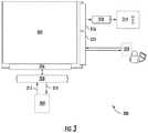
- FIG. 3depicts a wireless communication system (WCS) 300 according to example embodiments of the present disclosure.
- the system 300can include a wireless communication unit (WCU) 302 .
- the WCU 302can be the WCU 106 of FIGS. 1 and 2 .
- the WCU 302can be in communication with an electronic engine controller (EEC) 304 over a suitable interface 306 .
- EECelectronic engine controller
- the EEC 304can be the same as the EEC 104 of FIGS. 1 and 2 .
- the interface 306can be, for instance, a Telecommunications Industry Association (TIA) TIA-485 interface 306 .
- TIATelecommunications Industry Association
- the WCU 302 and the EEC 304can communicate via a connection 308 with, for instance, the TIA-485 interface 306 .
- the connection 308can, for example, accommodate other interfaces, such as an Ethernet connection, a wireless connection, or other interface.
- the connection 308can be, for example, a wired connection, such as, for example, an Ethernet connection.
- the connection 308can be, for example, a wireless connection, such as, for example, a BlueTooth® connection.
- the WCU 302can transmit addressing (e.g., memory location, bit size, etc.) information and/or acknowledgements 310 to the EEC 304 via the connection 308 .
- the WCU 302can receive data 312 from the EEC 304 via the connection 308 and can store the data in one or more memory device.
- the data 312can be, for instance, continuous engine operation data, such as thrust level inputs, engine response to thrust level inputs, vibration, flameout, fuel consumption, ignition state, N1 rotation, N2 rotation, N3 rotation, anti-ice capability, fuel filter state, fuel valve state, oil filter state, etc.
- the WCU 302can be configured to communicate the data 312 over a wireless network via an antenna 314 upon the occurrence of one or more trigger conditions, such as trigger conditions based on signals indicative of an aircraft being on the ground or near the ground.
- the antenna 314can be integrated into the WCU 302 .
- the WCU 302can include a radio frequency (RF) interface 316 .
- the antenna 314can be in communication with the RF interface 316 via an RF cable 318 .
- the antenna 314can be placed in the nacelle 50 of an aircraft 102 .
- the nacelle 50 of an aerial vehicle 100can be made of conductive materials, which can obstruct cellular reception and transmission.
- the antennacan be a directional antenna that is oriented near one or more gaps in the nacelle 50 to permit the antenna 314 to communicate directionally outside of the nacelle 50 when the aerial vehicle 100 is landing or upon the occurrence of other trigger conditions.
- the WCU 302can include an interface for communicating with a portable maintenance access terminal (PMAT) 320 .
- the access terminalcan be implemented, for instance, on a laptop, tablet, mobile device, or other suitable computing device.
- the interfacecan be, for instance, a Generic Stream Encapsulation (GSE) interface 322 or other suitable interface.
- GSEGeneric Stream Encapsulation
- the PMAT 320can be used by a maintenance person to calibrate, troubleshoot, initialize, test, etc. the WCU 302 .
- the WCU 302can communicate using wireless communication.
- the wireless communicationcan be performed using any suitable wireless technique and/or protocol.
- the wireless communicationcan be performed using peer-to-peer communications, network communications, cellular-based communications, satellite-based communications, etc.
- the wireless communicationscan be performed using Wi-Fi, Bluetooth, ZigBee, etc.
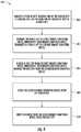
- FIG. 4depicts a flow diagram of an example method ( 400 ) for key management.
- the method of FIG. 4can be implemented using, for instance, the WCU 302 of FIG. 3 .
- FIG. 4depicts steps performed in a particular order for purposes of illustration and discussion. Those of ordinary skill in the art, using the disclosures provided herein, will understand that various steps of any of the methods disclosed herein can be adapted, modified, rearranged, or modified in various ways without deviating from the scope of the present disclosure.
- a pair of keyscan be generated.
- the WCU 302can generate a pair of keys.
- the WCU 302can be associated with an engine and/or an aerial vehicle.
- One of the pair of keyscan include a private key.
- One of the pair of keyscan include a public key.
- the public keycan be a key obtainable and usable by any party for encrypting a message to the WCU 302 .
- the private keycan be a key known only by the WCU 302 that is used to decrypt messages encrypted by the public key.
- the public keycan be transmitted to a first remote computing device.
- the WCU 302can transmit the public key to a key server.
- the first remote computing devicecan be associated with a ground system.
- the first remote computing devicecan be a secure key server addressable by a fixed Internet Protocol address.
- the first remote computing devicecan transmit the public key to a second remote computing device.
- the second remote computing devicecan be associated with a ground system.
- the second remote computing devicecan be a destination server addressable by a fixed Internet Protocol address.
- a host keycan be received from the first remote computing device.
- the WCU 302can receive a host key from the key server.
- the host keycan have been received by the first remote computing device from the second remote computing device.
- the host keycan be a public key associated with the second remote computing device.
- the second remote computing devicecan be accessed using the private key.
- the WCU 302can access the second remote computing device using the private key.
- a request from the second remote computing devicecan be verified using the host key.
- the WCU 302can verify a request from the second remote computing device using the host key.
- a bulk transfer of data to the destination servercan be initiated.
- the WCU 302can initiate a bulk transfer of data to the destination server.
- the destination servercan forward the transferred data to a third remote computing device.
- the third remote computing devicecan include a data lake.
- the third remote computing devicecan include a data storage repository.
- the third remote computing devicecan include a database.
- FIG. 5depicts a block diagram of an example computing system that can be used to implement a wireless communication unit (WCU) 500 , such as WCU 302 , or other systems according to example embodiments of the present disclosure.
- the WCU 500can include one or more computing device(s) 502 .
- the one or more computing device(s) 502can include one or more processor(s) 504 and one or more memory device(s) 506 .
- the one or more processor(s) 504can include any suitable processing device, such as a microprocessor, microcontroller, integrated circuit, logic device, or other suitable processing device.
- the one or more memory device(s) 506can include one or more computer-readable media, including, but not limited to, non-transitory computer-readable media, RAM, ROM, hard drives, flash drives, or other memory devices.
- the one or more memory device(s) 506can store information accessible by the one or more processor(s) 504 , including computer-readable instructions 508 that can be executed by the one or more processor(s) 504 .
- the instructions 508can be any set of instructions that when executed by the one or more processor(s) 504 , cause the one or more processor(s) 504 to perform operations.
- the instructions 508can be software written in any suitable programming language or can be implemented in hardware.
- the instructions 508can be executed by the one or more processor(s) 504 to cause the one or more processor(s) 504 to perform operations, such as the operations for recording and communicating engine data, as described with reference to FIG. 4 , and/or any other operations or functions of the one or more computing device(s) 502 .
- the memory device(s) 506can further store data 510 that can be accessed by the processors 504 .
- the data 510can include data associated with engine performance, engine operation, engine failure, errors in engine performance, errors in engine operation, errors in engine behavior, expected engine behavior, actual engine behavior, etc., as described herein.
- the data 510can include one or more table(s), function(s), algorithm(s), model(s), equation(s), etc. according to example embodiments of the present disclosure.
- the one or more computing device(s) 502can also include a communication interface 512 used to communicate, for example, with the other components of system.
- the communication interface 512can accommodate communications with the EEC 304 , the antenna 314 , the PMAT 320 , a ground control system, other WCUs 302 , a central computing device, any other device, and/or any combination of the foregoing.
- the communication interface 512can include any suitable components for interfacing with one or more network(s), including for example, transmitters, receivers, transceivers, ports, controllers, antennas, or other suitable components.
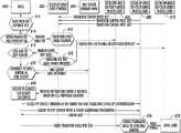
- FIG. 6depicts a sequence diagram of an example method according to example embodiments of the present disclosure.
- the WCU 600can have a need for a pair of encryption keys.
- the WCU 600can be new and need a first pair of encryption keys.
- a pair of encryption keys currently stored by the WCU 600can expire.
- the WCU 600can generate a pair of encryption keys.
- the pair of encryption keyscan include a public key and a private key.
- the WCU 600can transmit (e.g., send, transfer, etc.) the public key to a secure key server 602 .
- the secure key servercan be addressable by a fixed Internet Protocol (IP) address.
- IPInternet Protocol
- the WCU 600can login to the secure key server 602 with a login and/or a password.
- the secure key server 602can receive one or more server host keys from one or more destination servers 606 , 608 , 610 .
- the one or more destination servers 606 , 608 , 610can communicate via Secure Shell (SSH) using the one or more server host keys and/or the pair of keys.
- SSHSecure Shell
- the one or more destination servers 606 , 608 , 610can be addressable at one or more fixed IP addresses.
- the one or more destination servers 606 , 608 , 610can be protected with a password.
- the WCU 600can receive the one or more server host keys from the secure key server 602 .
- the one or more destination servers 606 , 608 , 610can receive the public key from the secure key server 602 using a transfer protocol that uses SSH to encrypt messages, such as Secure File Transfer Protocol (SFTP), Secure Copy (SCP), etc.
- SFTPSecure File Transfer Protocol
- SCPSecure Copy
- the WCU 600can transmit a Domain Name System (DNS) query to a DNS server 604 . Also at ( 622 ), the DNS server 604 can transmit a DNS response to the WCU 600 .
- the WCU 600can receive an IP address for a closest destination server of the one or more destination servers 606 , 608 , 610 . A determination of the closest destination server 608 can be made based on a provided cell location.
- the WCU 600can access the closest destination server 608 through a Secure Shell (SSH) tunnel with the private key.
- SSHSecure Shell
- the WCU 600can use the server host key to verify the identity of the closest destination server 608 .
- the WCU 600can log into a closest destination file transfer protocol (FTP) server 608 with a username and/or a password.
- FTPfile transfer protocol
- the WCU 600can receive a Login acknowledgement from the closest destination server 608 .
- the WCU 600can initiate a bulk transfer of data to the closest destination server 608 .
- the closest destination server 608can forward the data to a data lake 628 .
- any data transmitted to any of the one or more destination servers 606 , 608 , 610can be forwarded to the data lake 628 .
Landscapes
- Engineering & Computer Science (AREA)
- Computer Security & Cryptography (AREA)
- Computer Networks & Wireless Communication (AREA)
- Signal Processing (AREA)
- Selective Calling Equipment (AREA)
Abstract
Description
Claims (19)
Priority Applications (1)
| Application Number | Priority Date | Filing Date | Title |
|---|---|---|---|
| US15/632,488US10764747B2 (en) | 2016-06-30 | 2017-06-26 | Key management for wireless communication system for communicating engine data |
Applications Claiming Priority (2)
| Application Number | Priority Date | Filing Date | Title |
|---|---|---|---|
| US201662356633P | 2016-06-30 | 2016-06-30 | |
| US15/632,488US10764747B2 (en) | 2016-06-30 | 2017-06-26 | Key management for wireless communication system for communicating engine data |
Publications (2)
| Publication Number | Publication Date |
|---|---|
| US20180007547A1 US20180007547A1 (en) | 2018-01-04 |
| US10764747B2true US10764747B2 (en) | 2020-09-01 |
Family
ID=60806916
Family Applications (1)
| Application Number | Title | Priority Date | Filing Date |
|---|---|---|---|
| US15/632,488ActiveUS10764747B2 (en) | 2016-06-30 | 2017-06-26 | Key management for wireless communication system for communicating engine data |
Country Status (1)
| Country | Link |
|---|---|
| US (1) | US10764747B2 (en) |
Families Citing this family (2)
| Publication number | Priority date | Publication date | Assignee | Title |
|---|---|---|---|---|
| US10946973B2 (en)* | 2018-06-27 | 2021-03-16 | Honeywell International Inc. | System and method for providing end-use specific customization of gas turbine engine operation |
| GB2608103A (en)* | 2021-06-15 | 2022-12-28 | Continental Automotive Gmbh | Method and system to retrieve public keys in a memory constrained system |
Citations (95)
| Publication number | Priority date | Publication date | Assignee | Title |
|---|---|---|---|---|
| US5444861A (en) | 1992-06-01 | 1995-08-22 | United Technologies Corporation | System for downloading software |
| US5848367A (en) | 1996-09-13 | 1998-12-08 | Sony Corporation | System and method for sharing a non-volatile memory element as a boot device |
| JP2957370B2 (en) | 1993-01-14 | 1999-10-04 | 松下電工株式会社 | Automatic tracking antenna device |
| US6092008A (en) | 1997-06-13 | 2000-07-18 | Bateman; Wesley H. | Flight event record system |
| US6351603B2 (en) | 2000-03-09 | 2002-02-26 | Arwa Technologies, Inc. | Automatic water heating system |
| US6353734B1 (en) | 1999-06-25 | 2002-03-05 | Harris Corporation | Wireless spread spectrum ground link-based aircraft data communication system for engine event reporting |
| US6385513B1 (en) | 1998-12-08 | 2002-05-07 | Honeywell International, Inc. | Satellite emergency voice/data downlink |
| US20030158963A1 (en) | 2002-02-20 | 2003-08-21 | Sturdy James T. | Smartbridge for tactical network routing applications |
| US6628995B1 (en) | 2000-08-11 | 2003-09-30 | General Electric Company | Method and system for variable flight data collection |
| US20030225492A1 (en)* | 2002-05-29 | 2003-12-04 | Cope Gary G. | Flight data transmission via satellite link and ground storage of data |
| US6671589B2 (en) | 2001-02-13 | 2003-12-30 | William Holst | Method and apparatus to support remote and automatically initiated data loading and data acquisition of airborne computers using a wireless spread spectrum aircraft data services link |
| US20040186636A1 (en)* | 2001-10-01 | 2004-09-23 | Ehud Mendelson | Integrated aircraft early warning system, method for analyzing early warning data, and method for providing early warnings |
| US6831912B1 (en) | 2000-03-09 | 2004-12-14 | Raytheon Company | Effective protocol for high-rate, long-latency, asymmetric, and bit-error prone data links |
| US6868325B2 (en) | 2003-03-07 | 2005-03-15 | Honeywell International Inc. | Transient fault detection system and method using Hidden Markov Models |
| US6894611B2 (en) | 2002-09-23 | 2005-05-17 | General Electric Company | Method and system for uploading and downloading engine control data |
| US7218277B1 (en) | 2005-11-14 | 2007-05-15 | Aviation Communication & Surveillance Systems, Llc | Antenna failure detection |
| US20080272915A1 (en) | 2007-05-04 | 2008-11-06 | Pratt & Whitney Canada Corp. | Equipment monitoring system and method |
| US20090012691A1 (en)* | 2003-07-23 | 2009-01-08 | Harris Corporation | Wireless engine monitoring system |
| US20090058682A1 (en) | 2007-08-27 | 2009-03-05 | Honeywell International Inc. | Aircraft data network access for personal electronic devices |
| US20090186611A1 (en)* | 2007-12-18 | 2009-07-23 | Voyant International Corporation | Aircraft broadband wireless system and methods |
| US7595730B2 (en) | 2004-06-02 | 2009-09-29 | Panasonic Corporation | State recognition tag |
| US7636568B2 (en) | 2002-12-02 | 2009-12-22 | The Boeing Company | Remote aircraft manufacturing, monitoring, maintenance and management system |
| US7720442B2 (en) | 2005-11-15 | 2010-05-18 | Honeywell International, Inc. | Testing systems and methods for aircraft radios |
| US7844385B2 (en) | 2004-01-28 | 2010-11-30 | United Technologies Corporation | Microserver engine control card |
| US7908042B2 (en) | 2001-02-13 | 2011-03-15 | The Boeing Company | Methods and apparatus for wireless upload and download of aircraft data |
| US20110125348A1 (en) | 2009-11-23 | 2011-05-26 | Gordon Robert Andrew Sandell | Automatic Emergency Reporting |
| US8051031B2 (en) | 2008-02-06 | 2011-11-01 | The Boeing Company | Metadata for software aircraft parts |
| US8055393B2 (en) | 2008-02-06 | 2011-11-08 | The Boeing Company | Method and apparatus for loading software aircraft parts |
| US8121140B2 (en) | 2007-02-28 | 2012-02-21 | Honeywell International Inc. | Cost containment of mobile datalink communications |
| US8140298B2 (en) | 2007-04-06 | 2012-03-20 | Airbus Operations Sas | System and method for diagnosing aircraft components for maintenance purposes |
| US20120095662A1 (en) | 2010-10-14 | 2012-04-19 | Hamilton Sundstrand Corporation | Electronic engine control software reconfiguration for distributed eec operation |
| US8220038B1 (en) | 2008-04-25 | 2012-07-10 | Lockheed Martin Corporation | Method for securely routing communications |
| US8259002B2 (en) | 2010-12-10 | 2012-09-04 | Honeywell International Inc. | Radar altimeter antenna performance monitoring via reflected power measurements |
| US8285865B2 (en) | 2007-09-03 | 2012-10-09 | Airbus Operations | Method for transmitting ACARS messages over IP |
| US8284674B2 (en) | 2007-08-08 | 2012-10-09 | Honeywell International Inc. | Aircraft data link network routing |
| US8351927B2 (en) | 1995-11-14 | 2013-01-08 | Harris Corporation | Wireless ground link-based aircraft data communication system with roaming feature |
| US8401021B2 (en) | 2007-09-12 | 2013-03-19 | Proximetry, Inc. | Systems and methods for prioritizing wireless communication of aircraft |
| US8457034B2 (en) | 2008-06-17 | 2013-06-04 | Raytheon Company | Airborne communication network |
| US8462793B2 (en) | 2007-05-25 | 2013-06-11 | Caterpillar Inc. | System for strategic management and communication of data in machine environments |
| US20130242864A1 (en)* | 2012-03-16 | 2013-09-19 | Airbus Operations (Sas) | Method and system for transmitting data in a network of aircraft in flight |
| US8615384B2 (en) | 2007-10-31 | 2013-12-24 | The Boeing Company | Method and apparatus for simulating aircraft data processing systems |
| US20140013002A1 (en) | 2012-07-09 | 2014-01-09 | The Boeing Company | System and method for air-to-ground data streaming |
| US8639401B2 (en) | 2011-09-20 | 2014-01-28 | The Boeing Company | Dynamic adaptation of trigger thresholds to manage when data messages are transmitted |
| US20140068265A1 (en) | 2012-08-30 | 2014-03-06 | Raytheon Company | Method and system for transmitting data within a secure computer system |
| US8683266B2 (en) | 2010-03-03 | 2014-03-25 | Airbus Operations S.A.S. | Methods and devices for configuration validation of a complex multi-element system |
| US8699403B2 (en) | 2007-03-30 | 2014-04-15 | Livetv, Llc | Aircraft communications system with network selection controller and associated method |
| US8723692B2 (en) | 2002-11-21 | 2014-05-13 | Systems And Software Enterprises, Llc | Secure terminal data loader apparatus and method for a mobile platform |
| US8732812B2 (en) | 2008-10-20 | 2014-05-20 | Airbus Operations | Method of operating an item of on-board equipment, associated equipment and aircraft comprising such equipment |
| US8781982B1 (en) | 2011-09-23 | 2014-07-15 | Lockheed Martin Corporation | System and method for estimating remaining useful life |
| US8798817B2 (en) | 2012-01-31 | 2014-08-05 | Gulfstream Aerospace Corporation | Methods and systems for requesting and retrieving aircraft data during flight of an aircraft |
| US8823357B2 (en) | 2011-08-24 | 2014-09-02 | Spectralux Corporation | Radio frequency power amplifier protection system |
| US8856277B2 (en) | 2007-04-06 | 2014-10-07 | Airbus | System enabling communication between an aircraft-based computer network and a ground-based computer network |
| US8881294B2 (en) | 2011-02-18 | 2014-11-04 | Honeywell International Inc. | Methods and systems for securely uploading files onto aircraft |
| US8903601B2 (en) | 2009-12-09 | 2014-12-02 | Lufthansa Technik Ag | Line replaceable unit for an aircraft |
| US8984346B2 (en) | 2011-07-18 | 2015-03-17 | Airbus Operations Sas | Method for automatically reloading software and a device for automatically reloading software |
| US8988249B2 (en) | 2009-10-08 | 2015-03-24 | Connectif Solutions Inc. | System, method and integrated circuit chip for wireless multi-network meter reading |
| US8997197B2 (en) | 2012-12-12 | 2015-03-31 | Citrix Systems, Inc. | Encryption-based data access management |
| US9026279B2 (en) | 2012-06-06 | 2015-05-05 | Harris Corporation | Wireless engine monitoring system and configurable wireless engine sensors |
| US9026273B2 (en) | 2012-06-06 | 2015-05-05 | Harris Corporation | Wireless engine monitoring system with multiple hop aircraft communications capability and on-board processing of engine data |
| US9038047B2 (en) | 2007-11-27 | 2015-05-19 | The Boeing Company | Aircraft software part library |
| US20150161618A1 (en) | 2013-12-05 | 2015-06-11 | The Boeing Company | Aircraft Configuration and Software Part Management Using a Configuration Software Part |
| CN204495911U (en) | 2015-01-14 | 2015-07-22 | 无锡睿思凯科技有限公司 | A kind of model airplane remote controller antenna condition detection system |
| US9092629B2 (en) | 2007-04-16 | 2015-07-28 | The Directv Group, Inc. | Method and apparatus for authenticating a code image upon starting a device |
| US9100361B1 (en) | 2008-04-25 | 2015-08-04 | Lockheed Martin Corporation | Secure routing module |
| US20150222604A1 (en) | 2011-12-21 | 2015-08-06 | Ssh Communications Security Oyj | Automated Access, Key, Certificate, and Credential Management |
| US20150244683A1 (en) | 2012-08-29 | 2015-08-27 | Gerald Schreiber | Method and system for assigning information contents |
| US9124580B1 (en) | 2014-02-07 | 2015-09-01 | The Boeing Company | Method and system for securely establishing cryptographic keys for aircraft-to-aircraft communications |
| US20150276837A1 (en) | 2014-03-31 | 2015-10-01 | Samsung Electronics Co., Ltd. | Electronic device and antenna state determining method of the electronic device |
| US20150293765A1 (en) | 2014-04-11 | 2015-10-15 | The Boeing Company | Vehicle Configuration Driven Loading of Software Parts |
| US20150330869A1 (en) | 2012-06-06 | 2015-11-19 | Harris Corporation | Wireless engine monitoring system and associated engine wireless sensor network |
| US9208308B2 (en) | 2007-11-27 | 2015-12-08 | The Boeing Company | Alternate parts signature list file |
| US9225765B2 (en) | 2007-11-27 | 2015-12-29 | The Boeing Company | Onboard electronic distribution system |
| US20160075443A1 (en) | 2014-09-15 | 2016-03-17 | L-3 Communications Corporation | Fail safe aircraft monitoring and tracking |
| US20160092192A1 (en) | 2014-09-26 | 2016-03-31 | Airbus Operations (S.A.S.) | System and method for automatic reloading of software into embarked equipment |
| US20160098259A1 (en) | 2014-10-02 | 2016-04-07 | The Boeing Company | Software Aircraft Part Installation System |
| US9313276B2 (en) | 2012-03-13 | 2016-04-12 | Ge Aviation Systems Llc | Method for transmitting aircraft flight data |
| US20160110179A1 (en) | 2012-12-20 | 2016-04-21 | Lufthansa Technik Ag | Data loading device and data loading method for loading software into aircraft systems |
| US20160124738A1 (en) | 2014-05-16 | 2016-05-05 | Rosemount Aerospace Inc. | Tablet based airborne data loader |
| US20160154391A1 (en) | 2014-11-27 | 2016-06-02 | Airbus Operations Limited | Avionics networks |
| US9369548B2 (en) | 2013-06-25 | 2016-06-14 | The Boeing Company | Arinc 629 ethernet converter |
| US9390381B2 (en) | 2014-03-31 | 2016-07-12 | Shahram Davari | Intelligent water heater controller |
| US20160203659A1 (en) | 2013-05-22 | 2016-07-14 | Air China Limited | Apparatus and Method for Testing Aircraft Message Trigger Logics |
| US20160200455A1 (en) | 2015-01-09 | 2016-07-14 | Garmin International, Inc. | Line replacement unit (lru) replacement process |
| US20160219022A1 (en) | 2015-01-22 | 2016-07-28 | Dell Products L.P. | Secure shell public key audit system |
| US9420595B2 (en) | 2010-07-13 | 2016-08-16 | United Technologies Corporation | Communication of avionic data |
| US9418493B1 (en) | 2015-04-30 | 2016-08-16 | The Boeing Company | Methods and systems for data analytics |
| EP2579473B1 (en) | 2011-10-06 | 2016-08-17 | The Boeing Company | Aircraft emulation system |
| US9426650B2 (en) | 2014-10-31 | 2016-08-23 | Gogo Llc | Autonomous-mode content delivery and key management |
| US20160257429A1 (en) | 2015-03-03 | 2016-09-08 | Honeywell International Inc. | Aircraft lru data collection and reliability prediction |
| US20160314632A1 (en) | 2015-04-24 | 2016-10-27 | The Boeing Company | System and method for detecting vehicle system faults |
| US9481473B2 (en) | 2013-03-15 | 2016-11-01 | Rolls-Royce North American Technologies, Inc. | Distributed control system with smart actuators and sensors |
| US9490876B2 (en) | 2014-02-20 | 2016-11-08 | Samsung Electronics Co., Ltd. | Electronic device and operating method thereof |
| US9576404B2 (en) | 2004-09-16 | 2017-02-21 | Harris Corporation | System and method of transmitting data from an aircraft |
| US9639997B2 (en) | 2013-05-22 | 2017-05-02 | Air China Limited | Test apparatus and test method based on DFDAU |
| US20170187539A1 (en)* | 2014-09-14 | 2017-06-29 | Thompson Aerospace, Inc. | Method and system for security and authentication of aircraft data transmissions |
- 2017
- 2017-06-26USUS15/632,488patent/US10764747B2/enactiveActive
Patent Citations (97)
| Publication number | Priority date | Publication date | Assignee | Title |
|---|---|---|---|---|
| US5444861A (en) | 1992-06-01 | 1995-08-22 | United Technologies Corporation | System for downloading software |
| JP2957370B2 (en) | 1993-01-14 | 1999-10-04 | 松下電工株式会社 | Automatic tracking antenna device |
| US8351927B2 (en) | 1995-11-14 | 2013-01-08 | Harris Corporation | Wireless ground link-based aircraft data communication system with roaming feature |
| US5848367A (en) | 1996-09-13 | 1998-12-08 | Sony Corporation | System and method for sharing a non-volatile memory element as a boot device |
| US6092008A (en) | 1997-06-13 | 2000-07-18 | Bateman; Wesley H. | Flight event record system |
| US6385513B1 (en) | 1998-12-08 | 2002-05-07 | Honeywell International, Inc. | Satellite emergency voice/data downlink |
| US6353734B1 (en) | 1999-06-25 | 2002-03-05 | Harris Corporation | Wireless spread spectrum ground link-based aircraft data communication system for engine event reporting |
| US6351603B2 (en) | 2000-03-09 | 2002-02-26 | Arwa Technologies, Inc. | Automatic water heating system |
| US6831912B1 (en) | 2000-03-09 | 2004-12-14 | Raytheon Company | Effective protocol for high-rate, long-latency, asymmetric, and bit-error prone data links |
| US6628995B1 (en) | 2000-08-11 | 2003-09-30 | General Electric Company | Method and system for variable flight data collection |
| US6671589B2 (en) | 2001-02-13 | 2003-12-30 | William Holst | Method and apparatus to support remote and automatically initiated data loading and data acquisition of airborne computers using a wireless spread spectrum aircraft data services link |
| US7908042B2 (en) | 2001-02-13 | 2011-03-15 | The Boeing Company | Methods and apparatus for wireless upload and download of aircraft data |
| US20040186636A1 (en)* | 2001-10-01 | 2004-09-23 | Ehud Mendelson | Integrated aircraft early warning system, method for analyzing early warning data, and method for providing early warnings |
| US20030158963A1 (en) | 2002-02-20 | 2003-08-21 | Sturdy James T. | Smartbridge for tactical network routing applications |
| US20030225492A1 (en)* | 2002-05-29 | 2003-12-04 | Cope Gary G. | Flight data transmission via satellite link and ground storage of data |
| US6894611B2 (en) | 2002-09-23 | 2005-05-17 | General Electric Company | Method and system for uploading and downloading engine control data |
| US8723692B2 (en) | 2002-11-21 | 2014-05-13 | Systems And Software Enterprises, Llc | Secure terminal data loader apparatus and method for a mobile platform |
| US7636568B2 (en) | 2002-12-02 | 2009-12-22 | The Boeing Company | Remote aircraft manufacturing, monitoring, maintenance and management system |
| US6868325B2 (en) | 2003-03-07 | 2005-03-15 | Honeywell International Inc. | Transient fault detection system and method using Hidden Markov Models |
| US7755512B2 (en) | 2003-07-23 | 2010-07-13 | Harris Corporation | Wireless engine monitoring system |
| US20090012691A1 (en)* | 2003-07-23 | 2009-01-08 | Harris Corporation | Wireless engine monitoring system |
| US9367970B2 (en) | 2003-07-23 | 2016-06-14 | Harris Corporation | Wireless engine monitoring system |
| US7844385B2 (en) | 2004-01-28 | 2010-11-30 | United Technologies Corporation | Microserver engine control card |
| US7595730B2 (en) | 2004-06-02 | 2009-09-29 | Panasonic Corporation | State recognition tag |
| US9576404B2 (en) | 2004-09-16 | 2017-02-21 | Harris Corporation | System and method of transmitting data from an aircraft |
| US7218277B1 (en) | 2005-11-14 | 2007-05-15 | Aviation Communication & Surveillance Systems, Llc | Antenna failure detection |
| US7720442B2 (en) | 2005-11-15 | 2010-05-18 | Honeywell International, Inc. | Testing systems and methods for aircraft radios |
| US8121140B2 (en) | 2007-02-28 | 2012-02-21 | Honeywell International Inc. | Cost containment of mobile datalink communications |
| US8699403B2 (en) | 2007-03-30 | 2014-04-15 | Livetv, Llc | Aircraft communications system with network selection controller and associated method |
| US8140298B2 (en) | 2007-04-06 | 2012-03-20 | Airbus Operations Sas | System and method for diagnosing aircraft components for maintenance purposes |
| US8856277B2 (en) | 2007-04-06 | 2014-10-07 | Airbus | System enabling communication between an aircraft-based computer network and a ground-based computer network |
| US9092629B2 (en) | 2007-04-16 | 2015-07-28 | The Directv Group, Inc. | Method and apparatus for authenticating a code image upon starting a device |
| US20080272915A1 (en) | 2007-05-04 | 2008-11-06 | Pratt & Whitney Canada Corp. | Equipment monitoring system and method |
| US8462793B2 (en) | 2007-05-25 | 2013-06-11 | Caterpillar Inc. | System for strategic management and communication of data in machine environments |
| US8284674B2 (en) | 2007-08-08 | 2012-10-09 | Honeywell International Inc. | Aircraft data link network routing |
| US20090058682A1 (en) | 2007-08-27 | 2009-03-05 | Honeywell International Inc. | Aircraft data network access for personal electronic devices |
| US8285865B2 (en) | 2007-09-03 | 2012-10-09 | Airbus Operations | Method for transmitting ACARS messages over IP |
| US8401021B2 (en) | 2007-09-12 | 2013-03-19 | Proximetry, Inc. | Systems and methods for prioritizing wireless communication of aircraft |
| US8615384B2 (en) | 2007-10-31 | 2013-12-24 | The Boeing Company | Method and apparatus for simulating aircraft data processing systems |
| US9225765B2 (en) | 2007-11-27 | 2015-12-29 | The Boeing Company | Onboard electronic distribution system |
| US9208308B2 (en) | 2007-11-27 | 2015-12-08 | The Boeing Company | Alternate parts signature list file |
| US9038047B2 (en) | 2007-11-27 | 2015-05-19 | The Boeing Company | Aircraft software part library |
| US20090186611A1 (en)* | 2007-12-18 | 2009-07-23 | Voyant International Corporation | Aircraft broadband wireless system and methods |
| US8055393B2 (en) | 2008-02-06 | 2011-11-08 | The Boeing Company | Method and apparatus for loading software aircraft parts |
| US8051031B2 (en) | 2008-02-06 | 2011-11-01 | The Boeing Company | Metadata for software aircraft parts |
| US8220038B1 (en) | 2008-04-25 | 2012-07-10 | Lockheed Martin Corporation | Method for securely routing communications |
| US9100361B1 (en) | 2008-04-25 | 2015-08-04 | Lockheed Martin Corporation | Secure routing module |
| US8457034B2 (en) | 2008-06-17 | 2013-06-04 | Raytheon Company | Airborne communication network |
| US8732812B2 (en) | 2008-10-20 | 2014-05-20 | Airbus Operations | Method of operating an item of on-board equipment, associated equipment and aircraft comprising such equipment |
| US8988249B2 (en) | 2009-10-08 | 2015-03-24 | Connectif Solutions Inc. | System, method and integrated circuit chip for wireless multi-network meter reading |
| US20110125348A1 (en) | 2009-11-23 | 2011-05-26 | Gordon Robert Andrew Sandell | Automatic Emergency Reporting |
| US8903601B2 (en) | 2009-12-09 | 2014-12-02 | Lufthansa Technik Ag | Line replaceable unit for an aircraft |
| US8683266B2 (en) | 2010-03-03 | 2014-03-25 | Airbus Operations S.A.S. | Methods and devices for configuration validation of a complex multi-element system |
| US9420595B2 (en) | 2010-07-13 | 2016-08-16 | United Technologies Corporation | Communication of avionic data |
| US20120095662A1 (en) | 2010-10-14 | 2012-04-19 | Hamilton Sundstrand Corporation | Electronic engine control software reconfiguration for distributed eec operation |
| US8259002B2 (en) | 2010-12-10 | 2012-09-04 | Honeywell International Inc. | Radar altimeter antenna performance monitoring via reflected power measurements |
| US8881294B2 (en) | 2011-02-18 | 2014-11-04 | Honeywell International Inc. | Methods and systems for securely uploading files onto aircraft |
| US8984346B2 (en) | 2011-07-18 | 2015-03-17 | Airbus Operations Sas | Method for automatically reloading software and a device for automatically reloading software |
| US8823357B2 (en) | 2011-08-24 | 2014-09-02 | Spectralux Corporation | Radio frequency power amplifier protection system |
| US8639401B2 (en) | 2011-09-20 | 2014-01-28 | The Boeing Company | Dynamic adaptation of trigger thresholds to manage when data messages are transmitted |
| US8781982B1 (en) | 2011-09-23 | 2014-07-15 | Lockheed Martin Corporation | System and method for estimating remaining useful life |
| EP2579473B1 (en) | 2011-10-06 | 2016-08-17 | The Boeing Company | Aircraft emulation system |
| US20150222604A1 (en) | 2011-12-21 | 2015-08-06 | Ssh Communications Security Oyj | Automated Access, Key, Certificate, and Credential Management |
| US8798817B2 (en) | 2012-01-31 | 2014-08-05 | Gulfstream Aerospace Corporation | Methods and systems for requesting and retrieving aircraft data during flight of an aircraft |
| US9313276B2 (en) | 2012-03-13 | 2016-04-12 | Ge Aviation Systems Llc | Method for transmitting aircraft flight data |
| US20130242864A1 (en)* | 2012-03-16 | 2013-09-19 | Airbus Operations (Sas) | Method and system for transmitting data in a network of aircraft in flight |
| US9026279B2 (en) | 2012-06-06 | 2015-05-05 | Harris Corporation | Wireless engine monitoring system and configurable wireless engine sensors |
| US20150330869A1 (en) | 2012-06-06 | 2015-11-19 | Harris Corporation | Wireless engine monitoring system and associated engine wireless sensor network |
| US9026273B2 (en) | 2012-06-06 | 2015-05-05 | Harris Corporation | Wireless engine monitoring system with multiple hop aircraft communications capability and on-board processing of engine data |
| US20140013002A1 (en) | 2012-07-09 | 2014-01-09 | The Boeing Company | System and method for air-to-ground data streaming |
| US20150244683A1 (en) | 2012-08-29 | 2015-08-27 | Gerald Schreiber | Method and system for assigning information contents |
| US20140068265A1 (en) | 2012-08-30 | 2014-03-06 | Raytheon Company | Method and system for transmitting data within a secure computer system |
| US8997197B2 (en) | 2012-12-12 | 2015-03-31 | Citrix Systems, Inc. | Encryption-based data access management |
| US20160110179A1 (en) | 2012-12-20 | 2016-04-21 | Lufthansa Technik Ag | Data loading device and data loading method for loading software into aircraft systems |
| US9481473B2 (en) | 2013-03-15 | 2016-11-01 | Rolls-Royce North American Technologies, Inc. | Distributed control system with smart actuators and sensors |
| US9639997B2 (en) | 2013-05-22 | 2017-05-02 | Air China Limited | Test apparatus and test method based on DFDAU |
| US20160203659A1 (en) | 2013-05-22 | 2016-07-14 | Air China Limited | Apparatus and Method for Testing Aircraft Message Trigger Logics |
| US9369548B2 (en) | 2013-06-25 | 2016-06-14 | The Boeing Company | Arinc 629 ethernet converter |
| US20150161618A1 (en) | 2013-12-05 | 2015-06-11 | The Boeing Company | Aircraft Configuration and Software Part Management Using a Configuration Software Part |
| US9124580B1 (en) | 2014-02-07 | 2015-09-01 | The Boeing Company | Method and system for securely establishing cryptographic keys for aircraft-to-aircraft communications |
| US9490876B2 (en) | 2014-02-20 | 2016-11-08 | Samsung Electronics Co., Ltd. | Electronic device and operating method thereof |
| US20150276837A1 (en) | 2014-03-31 | 2015-10-01 | Samsung Electronics Co., Ltd. | Electronic device and antenna state determining method of the electronic device |
| US9390381B2 (en) | 2014-03-31 | 2016-07-12 | Shahram Davari | Intelligent water heater controller |
| US20150293765A1 (en) | 2014-04-11 | 2015-10-15 | The Boeing Company | Vehicle Configuration Driven Loading of Software Parts |
| US20160124738A1 (en) | 2014-05-16 | 2016-05-05 | Rosemount Aerospace Inc. | Tablet based airborne data loader |
| US20170187539A1 (en)* | 2014-09-14 | 2017-06-29 | Thompson Aerospace, Inc. | Method and system for security and authentication of aircraft data transmissions |
| US20160075443A1 (en) | 2014-09-15 | 2016-03-17 | L-3 Communications Corporation | Fail safe aircraft monitoring and tracking |
| US20160092192A1 (en) | 2014-09-26 | 2016-03-31 | Airbus Operations (S.A.S.) | System and method for automatic reloading of software into embarked equipment |
| US20160098259A1 (en) | 2014-10-02 | 2016-04-07 | The Boeing Company | Software Aircraft Part Installation System |
| US9426650B2 (en) | 2014-10-31 | 2016-08-23 | Gogo Llc | Autonomous-mode content delivery and key management |
| US20160154391A1 (en) | 2014-11-27 | 2016-06-02 | Airbus Operations Limited | Avionics networks |
| US20160200455A1 (en) | 2015-01-09 | 2016-07-14 | Garmin International, Inc. | Line replacement unit (lru) replacement process |
| CN204495911U (en) | 2015-01-14 | 2015-07-22 | 无锡睿思凯科技有限公司 | A kind of model airplane remote controller antenna condition detection system |
| US20160219022A1 (en) | 2015-01-22 | 2016-07-28 | Dell Products L.P. | Secure shell public key audit system |
| US20160257429A1 (en) | 2015-03-03 | 2016-09-08 | Honeywell International Inc. | Aircraft lru data collection and reliability prediction |
| US20160314632A1 (en) | 2015-04-24 | 2016-10-27 | The Boeing Company | System and method for detecting vehicle system faults |
| US9418493B1 (en) | 2015-04-30 | 2016-08-16 | The Boeing Company | Methods and systems for data analytics |
Also Published As
| Publication number | Publication date |
|---|---|
| US20180007547A1 (en) | 2018-01-04 |
Similar Documents
| Publication | Publication Date | Title |
|---|---|---|
| US10529150B2 (en) | Remote data loading for configuring wireless communication unit for communicating engine data | |
| US10819601B2 (en) | Wireless control unit server for conducting connectivity test | |
| US10681132B2 (en) | Protocol for communicating engine data to wireless communication unit | |
| US11061394B2 (en) | In-situ measurement logging by wireless communication unit for communicating engine data | |
| US10644630B2 (en) | Turbomachine with an electric machine assembly and method for operation | |
| CA2951671C (en) | System and method of reducing post-shutdown engine temperatures | |
| CN111594320B (en) | Method and system for engine operation | |
| US10200110B2 (en) | Aviation protocol conversion | |
| US9266618B2 (en) | Gas turbine engine turbine blade tip active clearance control system and method | |
| CN114291290B (en) | Flexible engine monitoring | |
| US11713990B2 (en) | Monitoring and control system for a flow duct | |
| US10764747B2 (en) | Key management for wireless communication system for communicating engine data | |
| US11956063B2 (en) | Engine control system | |
| US10470114B2 (en) | Wireless network selection | |
| JP2019535960A (en) | Turbine engine and cooling method thereof | |
| US11003603B2 (en) | Management of data transfers | |
| US10712377B2 (en) | Antenna diagnostics for wireless communication unit for communicating engine data | |
| US20110252295A1 (en) | Avionic data validation system | |
| US10467016B2 (en) | Managing an image boot | |
| US20160102679A1 (en) | Electromagnetic shaft-wheel coupling for arbitrary distribution of shaft torque in a turbine engine | |
| US20180005459A1 (en) | Triggering Scheme for Communicating Engine Data | |
| US20180002040A1 (en) | Data load connectivity test for wireless communication unit for communicating engine data | |
| EP4084445B1 (en) | Gas turbine engine communication data management function communicating via aircraft wireless gateway |
Legal Events
| Date | Code | Title | Description |
|---|---|---|---|
| AS | Assignment | Owner name:GE AVIATION SYSTEMS LLC, MICHIGAN Free format text:ASSIGNMENT OF ASSIGNORS INTEREST;ASSIGNORS:SCHOLTEN, MICHAEL CLAY;PRINCE, DANIEL JAMES;REIFFER, RICHARD JOHN, JR.;AND OTHERS;REEL/FRAME:042810/0045 Effective date:20170623 | |
| STPP | Information on status: patent application and granting procedure in general | Free format text:NON FINAL ACTION MAILED | |
| STPP | Information on status: patent application and granting procedure in general | Free format text:RESPONSE TO NON-FINAL OFFICE ACTION ENTERED AND FORWARDED TO EXAMINER | |
| STPP | Information on status: patent application and granting procedure in general | Free format text:FINAL REJECTION MAILED | |
| STPP | Information on status: patent application and granting procedure in general | Free format text:DOCKETED NEW CASE - READY FOR EXAMINATION | |
| STPP | Information on status: patent application and granting procedure in general | Free format text:NON FINAL ACTION MAILED | |
| STPP | Information on status: patent application and granting procedure in general | Free format text:NOTICE OF ALLOWANCE MAILED -- APPLICATION RECEIVED IN OFFICE OF PUBLICATIONS | |
| STCF | Information on status: patent grant | Free format text:PATENTED CASE | |
| MAFP | Maintenance fee payment | Free format text:PAYMENT OF MAINTENANCE FEE, 4TH YEAR, LARGE ENTITY (ORIGINAL EVENT CODE: M1551); ENTITY STATUS OF PATENT OWNER: LARGE ENTITY Year of fee payment:4 |