US10764133B2 - System and method to manage server configuration profiles in a data center - Google Patents
System and method to manage server configuration profiles in a data centerDownload PDFInfo
- Publication number
- US10764133B2 US10764133B2US15/961,332US201815961332AUS10764133B2US 10764133 B2US10764133 B2US 10764133B2US 201815961332 AUS201815961332 AUS 201815961332AUS 10764133 B2US10764133 B2US 10764133B2
- Authority
- US
- United States
- Prior art keywords
- data processing
- configuration
- change
- processing system
- setting
- Prior art date
- Legal status (The legal status is an assumption and is not a legal conclusion. Google has not performed a legal analysis and makes no representation as to the accuracy of the status listed.)
- Active
Links
Images


Classifications
- H—ELECTRICITY
- H04—ELECTRIC COMMUNICATION TECHNIQUE
- H04L—TRANSMISSION OF DIGITAL INFORMATION, e.g. TELEGRAPHIC COMMUNICATION
- H04L41/00—Arrangements for maintenance, administration or management of data switching networks, e.g. of packet switching networks
- H04L41/08—Configuration management of networks or network elements
- H04L41/0803—Configuration setting
- H04L41/0813—Configuration setting characterised by the conditions triggering a change of settings
- H04L41/0816—Configuration setting characterised by the conditions triggering a change of settings the condition being an adaptation, e.g. in response to network events
- H—ELECTRICITY
- H04—ELECTRIC COMMUNICATION TECHNIQUE
- H04L—TRANSMISSION OF DIGITAL INFORMATION, e.g. TELEGRAPHIC COMMUNICATION
- H04L12/00—Data switching networks
- H04L12/28—Data switching networks characterised by path configuration, e.g. LAN [Local Area Networks] or WAN [Wide Area Networks]
- H04L12/46—Interconnection of networks
- H04L12/4641—Virtual LANs, VLANs, e.g. virtual private networks [VPN]
- H—ELECTRICITY
- H04—ELECTRIC COMMUNICATION TECHNIQUE
- H04L—TRANSMISSION OF DIGITAL INFORMATION, e.g. TELEGRAPHIC COMMUNICATION
- H04L41/00—Arrangements for maintenance, administration or management of data switching networks, e.g. of packet switching networks
- H04L41/08—Configuration management of networks or network elements
- H04L41/0803—Configuration setting
- H04L41/084—Configuration by using pre-existing information, e.g. using templates or copying from other elements
Definitions
- This disclosuregenerally relates to information handling systems, and more particularly relates to managing server configuration profiles in a data center.
- An information handling systemgenerally processes, compiles, stores, and/or communicates information or data for business, personal, or other purposes. Because technology and information handling needs and requirements may vary between different applications, information handling systems may also vary regarding what information is handled, how the information is handled, how much information is processed, stored, or communicated, and how quickly and efficiently the information may be processed, stored, or communicated. The variations in information handling systems allow for information handling systems to be general or configured for a specific user or specific use such as financial transaction processing, reservations, enterprise data storage, or global communications. In addition, information handling systems may include a variety of hardware and software resources that may be configured to process, store, and communicate information and may include one or more computer systems, data storage systems, and networking systems.
- An information handling systemmay include first and second data processing systems and a configuration management system.
- the configuration management systemmay determine to change a first configuration setting for the first data processing system, modify a first configuration profile for the first data processing system to include the changed first configuration setting, determine that the change to a first configuration setting necessitates a change to a second configuration setting for the second data processing system, modify a second configuration profile for the second data processing system to include the changed second configuration setting, export the modified second configuration profile to the second data processing system, and export the modified first configuration profile to the first data processing system after exporting the modified second configuration profile to the second data processing system.
- FIG. 1is a block diagram of a data center according to an embodiment of the present disclosure
- FIG. 2is a block diagram of a server rack according to an embodiment of the present disclosure
- FIG. 3is a flowchart illustrating a method for applying operational system configuration profile templates in a data center according to an embodiment of the present disclosure
- FIG. 4is a flowchart illustrating a method for applying configuration setting changes in a data center according to an embodiment of the present disclosure
- FIG. 5is a flowchart illustrating a method for assessing configuration changes on applications running in a server according to an embodiment of the present disclosure.
- FIG. 6is a block diagram illustrating a generalized information handling system according to an embodiment of the present disclosure.
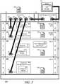
- FIG. 1illustrates an embodiment of a data center 100 including server aisle 110 , and a data center management controller (DCMC) 160 .
- Server aisle 110includes server racks 110 , 120 , 130 , 140 , and 150 .
- Server racks 120 , 130 , 140 , and 150include various equipment that operates to perform the data storage and processing functions of data center 100 .
- one or more elements of data center 100including the equipment in server racks 120 , 130 , 140 , and 150 and DCMC 160 can be realized as an information handling system.
- Each of server racks 110 , 120 , 130 , 140 , and 150includes a respective rack management controller (RMC) 112 , 122 , 132 , 142 , and 152 .
- RMCrack management controller
- RMCs 112 , 122 , 132 , 142 , and 152represent service processors that operate in accordance with an Intelligent Platform Management Interface (IPMI) functional implementation to provide monitoring, management, and maintenance functionality to the respective server racks 110 , 120 , 130 , 140 , and 150 , and to the equipment therein.
- IPMIIntelligent Platform Management Interface
- Examples of RMCs 112 , 122 , 132 , 142 , and 152can include service processors, such as baseboard management controllers (BMCs), an Integrated Dell Remote Access Controller (iDRAC), another service processor, or a combination thereof.
- BMCsbaseboard management controllers
- iDRACIntegrated Dell Remote Access Controller
- RMCs 112 , 122 , 132 , 142 , and 152 , and DCMC 160are connected together with various service processors associated with the equipment in server racks 110 , 120 , 130 , 140 , and 150 into a management network whereby the DCMC can remotely manage the equipment in the server racks.
- the equipment in server racks 110 , 120 , 130 , 140 , and 150include stand-alone servers, blade servers, storage arrays, I/O and network switches and routers, power supplies, and the like, as needed or desired.
- Each element of server racks 110 , 120 , 130 , 140 , and 150needs to be configured to operate within the overall processing environment of data center 100 .
- the configuration of each elementis particular to the function provided by the element, the physical and virtual locations of the elements on various data and storage networks of data center 100 , the desired management and environmental parameters of the data center and the particular elements, BIOS or UEFI settings, and the like.
- each element of server racks 110 , 120 , 130 , 140 , and 150includes a management controller such as a Baseboard Management Controller, or the like, that permits DCMC 160 to manage the configurations of the elements of the server racks.
- a management controllersuch as a Baseboard Management Controller, or the like, that permits DCMC 160 to manage the configurations of the elements of the server racks.
- each manageable parameter of the elements of server racks 110 , 120 , 130 , 140 , and 150may be individually managed, in practical fact, many of the manageable parameters of the elements of the server racks will have similar configuration settings as other similar elements of the server rack.
- BIOS settingssuch as system controller settings, system clock settings, system boot configurations and boot order, and the like may be the same for all stand-alone servers or blade servers of a particular type.
- the elements of server racks 110 , 120 , 130 , 140 , and 150are each configured based upon a Server Configuration Profile (SCP).
- SCPembodies the concept of performing server configuration through a single file.
- a SCPcan be generated in a XML or JSON format and can be exported to the elements of server racks 110 , 120 , 130 , 140 , and 150 with an Export Server Configuration operation.
- Configuration changescan be edited into the SCP and can be applied to one or more of the elements of server racks 110 , 120 , 130 , 140 , and 150 with an Import Server Configuration operation.
- server rack 110is associated with a SCP 114
- server rack 120is associated with a SCP 124
- server rack 130is associated with a SCP 134
- server rack 140is associated with a SCP 144
- server rack 150is associated with a SCP 154 .
- each element of server racks 110 , 120 , 130 , 140 , and 150will include its own SCP, and thus each of SCPs 114 , 124 , 134 , 144 , and 154 are illustrative of several SCPs, one for each element of the associated server rack.
- DCMC 160creates, maintains, and implements SCPs 162 for the various types of elements within server racks 110 , 120 , 130 , 140 , and 150 .
- An example of configuration settings that can be set utilizing SCPs 114 , 124 , 134 , 144 , and 154includes BIOS configuration settings, such as BIOS passwords, BIOS boot mode (e.g.
- BIOS boot orderand other configuration settings that are configurable via a BIOS setup utility
- network configuration settingssuch as static IP addresses, network adapter partitions, VLANs, and other network configuration settings
- storage configuration settingssuch as RAID configuration settings, boot image locations, virtual drive settings, and other network configuration settings
- management network settingssuch as management VLANs, environmental alarm limits, power limits and other management network settings, as needed or desired.
- FIG. 2illustrates a server rack 200 typical of server racks 110 , 120 , 130 , 140 , and 150 .
- Server rack 200includes a rack space that represents a standard server rack, such as a 19-inch rack equipment mounting frame or a 23-inch rack equipment mounting frame, and includes six rack units.
- the rack unitsrepresent special divisions of the rack space that are a standardized unit of, for example, 1.75 inches high.
- a piece of equipment that will fit into one of the rack unitsshall herein be referred to as a 1-U piece of equipment, another piece of equipment that takes up two of the rack units is commonly referred to as a 2-U piece of equipment, and so forth.
- rack unitsare numbered sequentially from the bottom to the top as 1U, 2U, 3U, 4U, 5U, and 6U.
- rack unitscan be defined by the Electronic Components Industry Association standards council.
- Server rack 200further includes a rack management controller 210 and a rack management switch 220 , and is illustrated as being populated with two 2-U servers 230 and 240 , and with two 1-U storage arrays 250 and 260 .
- 2-U server 230is installed in rack spaces 1U and 2U
- 2-U server 240is installed in rack spaces 3U and 4U
- 1-U storage array 250is installed in rack space 5U
- 1-U storage array 260is installed in rack space 6U.
- Rack management controller 210includes network connections 212 and 214
- rack switch 220includes network connections 222 , 223 , 224 , 225 , and 226 .
- rack management controller 210is connected via network connection 214 to a management network that includes a DCMC 280 similar to DCMC 160 , and is connected via network connection 212 to network connection 222 of rack switch 220 to extend the management network to servers 230 and 240 , and to storage arrays 250 and 260 .
- server 230includes a BMC 231 that is connected to network connection 223 via a network connection 232
- server 240includes a BMC 241 that is connected to network connection 224 via a network connection 242
- storage array 250includes a BMC 251 that is connected to network connection 225 via a network connection 252
- storage array 260includes a BMC 261 that is connected to network connection 226 via a network connection 262 .
- the management networkincludes RMC 210 , BMCs 231 , 241 , 251 , and 261 , and DCMC 280 .
- DCMC 280is configured to initiate management transactions with RMC 210 to monitor, manage, and maintain elements of server rack 200 , of management switch 220 , of servers 230 and 240 , and of storage arrays 250 , and 260 via respective BMCs 321 , 241 , 251 , and 261 .
- BMC 231operates to monitor, manage, and maintain server 230 .
- BMC 231accesses various sensors for monitoring various physical characteristics of the server, such as temperature sensors, fan speed sensors, voltage sensors on the various voltage rails, current sensors on the voltage rails, humidity sensors, and the like, to characterize the environmental conditions within which the server is operating.
- BMC 231further accesses various state information of the elements of server 230 , such as by accessing I/O state information related to the operating condition of the elements of the server, and the like, to further characterize the environmental conditions within the elements of the server.
- BMC 231further accesses various software and firmware information, such as processor loading information, memory and storage utilization information, network and I/O bandwidth information, and the like, to characterize the processing conditions of server 230 .
- BMC 231further operates to provide the monitoring information to RMC 210 and to DCMC 280 via the management network, as needed or desired.
- BMC 231utilizes the monitoring information from the server to provide inputs to control various physical operations of the server, such as fan speeds, voltage levels, processor clock rates, I/O speeds, and the like, to ensure that the environmental conditions of the server and the elements thereof remain within acceptable limits.
- BMC 231further operates to provide indications as to the environmental and processing conditions to RMC 210 and DCMC 280 , as needed or desired. For example, when temperature conditions within server 230 exceed a particular threshold, then BMC 231 can provide a high-temp indication to that effect to RMC 210 and the RMC can direct a heating/ventilation/air conditioning (HVAC) system of the data center to direct additional cooling to server 230 . Similarly, when temperature conditions within server 230 drop below another threshold, then BMC 231 can provide a low-temp indication to that effect to RMC 210 and the RMC can direct the HVAC system to direct less cooling to server 230 .
- HVACheating/ventilation/air conditioning
- BMC 231further utilizes the monitoring information from the server to provide inputs to control various processing conditions of the server. For example, when processing conditions, such as processor loading or memory utilization, within server 230 exceed a particular threshold, then BMC 231 can provide a high-utilization indication to that effect to DCMC 280 , and the DCMC can direct spare servers of the data center to come on line to offload the workload from the server. Similarly, when processing conditions within server 230 drop below another threshold, then BMC 231 can provide a low-utilization indication to that effect to DCMC 280 and the DCMC can direct initiate steps to shut down server 230 and place it into a pool of spare servers for the data center.
- processing conditionssuch as processor loading or memory utilization
- BMC 231In maintaining server 230 , BMC 231 operates to ensure that the operating thresholds, set points, and other limits are maintained, and to reset or change the thresholds, set points and other limits as needed or desired. Further, BMC 231 operates to maintain software and firmware in server 230 , as needed or desired. BMCs 241 , 251 , and 261 operate to monitor, manage, and maintain respective servers 240 , 250 , and 260 similarly to the way that BMC 231 operates on server 230 , as described above. Moreover, RMC 210 operates to monitor, manage, and maintain functions and features of server rack 200 , as needed or desired.
- RMC 210operates as a central node of the management network between BMCs 231 , 241 , 251 , and 261 , and DCMC 280 , colleting monitoring information from the BMCs and providing management and maintenance information to the BMCs, as needed or desired.
- DCMC 280includes a SCP manager 282 that operates to create, modify, and deploy SCPs for the elements of server rack 200 .
- rack switch 220includes a SCP 228
- servers 230 and 240include respective SCPs 238 and 248
- storage arrays 250 and 260include respective SCPs 258 and 268 .
- SCP manager 282can create, modify, and deploy SCPs 228 , 238 , 248 , 258 , and 268 separately and as needed or desired. For example, if it is determined that server 230 needs a new configuration setting applied, SCP manager 282 operates to modify a copy of SCP 238 maintained at DCMC 280 and to deploy the modified SCP to the server.
- SCP manager 282deploys SCPs by directly communicating the SCPs to the elements of server rack 200 for the elements to apply to themselves, as needed of desired.
- rack switch 220may include an in-band mechanism, such as a management VLAN that permits the rack switch to receive management information and to deploy the management information to the rack switch.
- SCP manager 282can deploy SCP 228 via the in-band mechanism to rack switch 220 , and the rack switch operates to make the modifications to its configuration as provided by the SCP.
- SCP manger 282deploys SCPs by communicating the SCPs to a management controller of the elements, and the management controller applies the SCPs to the associated elements.
- server 230includes BMC 231 .
- SCP manager 282can deploy SCP 238 via an out-of-band transaction to BMC 231 , and the BMC operates to make the modifications to the configuration of server 230 as provided by the SCP.
- SCP manager 282does not create, modify, and deploy SCPs individually on the elements of server rack 200 . Instead, SCP manager 282 maintains various operational SCP templates based upon different types or classes of elements within server rack 200 and within the data center that includes the server rack. For example, where elements of the data center are of a same type, such as where server racks are deployed with a common top-of-rack switch, or where a large number of blade servers of a particular model are deployed throughout the data center, SCP manager 282 can implement one operational SCP template for the top-of-rack switches and a different operational SCP template for the blade servers.
- SCP manager 282can more easily maintain the elements of the data center. For example, where a configuration setting that is common for a large number of the elements of the data center, such as a RTC setting, SCP manger 282 can make changes to the common setting in the smaller number of operational SCP templates and deploy the changes by exporting the templated SCPs across the data center. Then, only when a change effects only one element of the data center, such as a MAC or IP address, SCP manager can deploy changes to the individual SCPs as described above.
- SCP manager 282operates to maintain dependency information between the configuration settings in the operational SCP templates, and to deploy updated SCPs based upon the dependency information. For example, as noted above, many of the configuration settings for a particular type of equipment may be modified and deployed without reference to any other equipment in the data center.
- a serversuch as server 230 . Changes to the RTC setting of the server may not depend upon, interfere with, or be interfered with by any other equipment in the data center.
- the RTC setting of an operational SCP template for serversmay indicate that changes to the RTC setting of servers is not dependent upon any other equipment of the data center.
- a change to the boot directory of a servermay necessitate updating of one or more storage elements like storage arrays 250 and 260 , before a next boot cycle of the server is performed, and so the operational SCP template for servers may indicate that changes to the boot directory of servers must be accompanied by the consequent changes to storage arrays prior to any system reboot of the servers. Further, a change to a VLAN of a server may cause unintended loss of data if the other elements that are associated with the modified VLAN setting are not modified before the server.
- RMC 210 and BMC 242are to communicate with each other over a new VLAN, it may be necessary to first provide a modified SCP for rack switch 220 , setting up the rack switch to accommodate the new VLAN, before either the RMC or server 240 are updated.
- Table 1, belowillustrates an example of an operational SCP template for server equipment in a data center. It will be understood that, for some modifications to an operational SCP template, there will be multiple overlapping, and possibly conflicting dependencies. As such, an operational SCP template may further specify a priority of action for the dependency actions, as needed or desired.
- FIG. 3illustrates a method for applying operational SCP templates in a data center, starting at block 300 .
- Configuration setting changes to an operational SCP templateare determined in block 302 .
- the changesare evaluated with reference to the operations SCP template to identify the dependencies that are created by the configuration setting changes in block 304 .
- the change with the most dependencies to resolveis selected and the identified prior activities and modifications are performed on the identified equipment in block 306 .
- the mitigation of one or more dependencymay need to be resolved by the modification of one or more other operational SCP templates or individual SCPs, as needed or desired.
- a decisionis made as to whether or not the resolved dependency is the last unresolved dependency in decision block 308 .
- the “NO” branch of decision block 308is taken and the method returns to block 306 where the change with the next most dependencies to resolve is selected and the identified prior activities and modifications are performed on the identified equipment. If the resolved dependency is the last unresolved dependency, the “YES” branch of decision block 308 is taken, the operational SCP template is applied to the identified equipment in block 310 , and the method ends in block 312 .
- BMC 231includes a configuration manager 232 that operates to maintain the configuration options of server 230 , to determine when changes are made within the server, to determine from SCP manager 282 whether or not there are any dependencies related to the changes, and to take steps to mitigate the dependencies on server 230 .
- configuration manger 232is local to server 230 , but this is not necessarily so, and the functions and features of the configuration manager, as described below, may be applied equally to other equipment of data center 200 , as needed or desired.
- SCP manager 282also provides, on an as needed basis, a remediation policy to the BMC.
- the remediation policycan be provided as a file that includes the dependency information from the operational SCP template for server 230 , such that configuration manager 232 can determine when a configuration setting change involves any dependencies.
- configuration manager 232when configuration manager 232 detects a change to the configuration options of server 230 , the configuration manager provides a request to SCP manger 282 over the management network to request the remediation policy information. Then configuration manger 232 determines if the configuration change involves any dependencies. If so, then configuration manager 232 operates to implement the remediation steps associated with the dependencies, if the dependencies implicate configuration settings within server 230 . If the identified dependencies are outside of server 230 , and therefore beyond the ability of configuration manager 232 to remedy, then the configuration manager sends a request to SCP manager 282 indicating that the configuration manager intends to perform the configuration change, and requesting the SCP manger to perform the remedial actions on the other elements of data center 200 , as indicated by the remediation policy information.
- configuration manager 232can hold the requested configuration change from being implemented until SCP manager 282 indicates that the remediation actions have been performed. Then configuration manager 232 performs the requested configuration change.
- the amount of management network trafficis reduced because BMC 231 initiates action only when a configuration setting is requested to be changed. Otherwise, SPC manger 282 would be required to poll all the elements of the data center to ensure that all requested configuration changes are evaluated for potential dependencies, thus consuming an increased amount of the processing resources on the management network.
- the SCP managerwhen configuration manager 232 detects a configuration change request and requests the remediation policy information from SCP manger 282 , the SCP manager provides the full remediation policy for server 230 . In this way, configuration manager 232 has access to all of the dependency mitigation actions, and, on the assumption that one configuration change will be rapidly followed by other configuration change request, will not need to re-download the remediation policy information.
- the SCP managerwhen configuration manager 232 detects a configuration change request and requests the remediation policy information from SCP manger 282 , the SCP manager provides only the remediation policy information related to the requested configuration change.
- FIG. 4illustrates a method for applying configuration setting changes in a data center, starting at block 400 .
- a request to change a configuration setting of an element of a data centeris detected in block 402 .
- the element to be changedhas detected the change request.
- the element that detected the change requestissues a request to a DCMC to receive a remediation policy related to the change request in block 404 .
- the DCMCdetermines whether or not the requested change has any dependencies based upon the operational SCP template and provides a remediation policy in block 406 .
- a decisionis made by the element of the data center as to whether or not the remediation policy received from the DCMC indicates any dependencies related to the detected configuration setting change request in decision block 408 .
- the “NO” branch of decision block 408is taken, the requested configuration setting is changed in block 414 , and the method ends in block 416 .
- the remediation policy received from the DCMCindicates dependencies related to the detected configuration setting change request
- the “YES” branch of decision block 408is taken and the element of the data center requests the DCMC to perform any mitigations associated with the requested change on other elements of the data center in block 410 .
- a decisionis made as to whether or not the dependencies have been mitigated in decision block 412 . If not, the “NO” branch of decision block 412 is taken and the method returns to decision block 412 until the dependencies have been mitigated. When the dependencies have been mitigated, the “YES branch of decision block 412 is taken, the requested configuration setting is changed in block 414 , and the method ends in block 416 .
- server 240includes a host-to-management pass through 244 and BMC 241 includes a configuration manager 242 similar to configuration manager 232 .
- Host-to-management pass through 244represents an in-band agent resident in a hosted environment of server 240 that communicates management information between the hosted environment of the server and the out-of-band environment of BMC 241 .
- host-to-management pass through 244operates to track the software and applications operating on the hosted environment and to determine the hardware resources that are utilized by the software and applications.
- Host-to-management pass through 244then identifies the operating software and applications, along with the associated hardware resources utilized thereby, to configuration manger 242 .
- Communication manager 242operates to maintain the configuration options of server 240 , to determine when changes are made to the configuration settings of the server, and to determine whether the configuration setting changes impact the hardware resources of the operating software and applications on the hosted environment of the server.
- configuration manger 242 and host-to-management pass through 244are local to server 240 , but this is not necessarily so, and the functions and features of the configuration manager and the host-to-management pass through, as described below, may be applied equally to other equipment of data center 200 , as needed or desired.
- configuration manager 242determines that a configuration setting change will impact the hardware resources of the operating software and applications on the hosted environment of server 240 , the configuration manager operates to provide a warning that the proposed configuration setting changes may adversely impact the operation of the operating software and applications. Such a warning can be provided to a user of server 240 , or to DCMC 280 via the management network, as needed or desired. In addition to the warning, configuration manager 242 operates to prevent the proposed configuration changes until an authorization for such changes is received by the configuration manager, such as from the user or from DCMC 280 , as needed or desired.
- FIG. 5illustrates a method for assessing configuration changes on applications running in a server, starting at block 500 .
- An in-band agentsuch as a host-to-management pass through, detects the operating software and applications in the hosted environment of a particular piece of equipment in a data center in block 502 .
- the in-band agentcorrelates the operating software and applications with the hardware resources utilized thereby in block 504 .
- the in-band agentcommunicates information related to the operating software and applications and the associated hardware resources to a management controller of an out-of-band environment of the piece of equipment in block 506 .
- a decisionis made by the management controller as to whether or not a configuration setting change has been requested in decision block 508 .
- the “NO” branch of decision block 508is taken and the method loops to decision block 508 until a configuration setting change has been requested. After a configuration change has been requested, the “YES” branch of decision block 508 is taken and a decision is made as to whether or not the configuration setting change is associated with a hardware resource dependency in decision block 510 . If not, the “NO” branch of decision block 510 is taken, the configuration setting is changed in block 512 , and the method ends in block 514 .
- the “YES” branch of decision block 510is taken, the management controller provides an warning that the pending configuration setting change is associated with a hardware resource dependency and halts execution of the configuration setting change in block 516 , and the method ends in block 514 .
- FIG. 6illustrates a generalized embodiment of information handling system 600 .
- information handling system 600can include any instrumentality or aggregate of instrumentalities operable to compute, classify, process, transmit, receive, retrieve, originate, switch, store, display, manifest, detect, record, reproduce, handle, or utilize any form of information, intelligence, or data for business, scientific, control, entertainment, or other purposes.
- information handling system 600can be a personal computer, a laptop computer, a smart phone, a tablet device or other consumer electronic device, a network server, a network storage device, a switch router or other network communication device, or any other suitable device and may vary in size, shape, performance, functionality, and price.
- information handling system 600can include processing resources for executing machine-executable code, such as a central processing unit (CPU), a programmable logic array (PLA), an embedded device such as a System-on-a-Chip (SoC), or other control logic hardware.
- Information handling system 600can also include one or more computer-readable medium for storing machine-executable code, such as software or data.
- Additional components of information handling system 600can include one or more storage devices that can store machine-executable code, one or more communications ports for communicating with external devices, and various input and output (I/O) devices, such as a keyboard, a mouse, and a video display.
- Information handling system 600can also include one or more buses operable to transmit information between the various hardware components.
- Information handling system 600can include devices or modules that embody one or more of the devices or modules described above, and operates to perform one or more of the methods described above.
- Information handling system 600includes a processors 602 and 604 , a chipset 610 , a memory 620 , a graphics interface 630 , include a basic input and output system/extensible firmware interface (BIOS/EFI) module 640 , a disk controller 650 , a disk emulator 660 , an input/output (I/O) interface 670 , and a network interface 680 .
- BIOS/EFIbasic input and output system/extensible firmware interface
- Processor 602is connected to chipset 610 via processor interface 606
- processor 604is connected to the chipset via processor interface 608 .
- Memory 620is connected to chipset 610 via a memory bus 622 .
- Graphics interface 630is connected to chipset 610 via a graphics interface 632 , and provides a video display output 636 to a video display 634 .
- information handling system 600includes separate memories that are dedicated to each of processors 602 and 604 via separate memory interfaces.
- An example of memory 620includes random access memory (RAM) such as static RAM (SRAM), dynamic RAM (DRAM), non-volatile RAM (NV-RAM), or the like, read only memory (ROM), another type of memory, or a combination thereof.
- RAMrandom access memory
- SRAMstatic RAM
- DRAMdynamic RAM
- NV-RAMnon-volatile RAM
- ROMread only memory
- BIOS/EFI module 640disk controller 650 , and I/O interface 670 are connected to chipset 610 via an I/O channel 612 .
- I/O channel 612includes a Peripheral Component Interconnect (PCI) interface, a PCI-Extended (PCI-X) interface, a high-speed PCI-Express (PCIe) interface, another industry standard or proprietary communication interface, or a combination thereof.
- PCIPeripheral Component Interconnect
- PCI-XPCI-Extended
- PCIehigh-speed PCI-Express
- Chipset 610can also include one or more other I/O interfaces, including an Industry Standard Architecture (ISA) interface, a Small Computer Serial Interface (SCSI) interface, an Inter-Integrated Circuit (I 2 C) interface, a System Packet Interface (SPI), a Universal Serial Bus (USB), another interface, or a combination thereof.
- BIOS/EFI module 640includes BIOS/EFI code operable to detect resources within information handling system 600 , to provide drivers for the resources, initialize the resources, and access the resources.
- BIOS/EFI module 640includes code that operates to detect resources within information handling system 600 , to provide drivers for the resources, to initialize the resources, and to access the resources.
- Disk controller 650includes a disk interface 652 that connects the disc controller to a hard disk drive (HDD) 654 , to an optical disk drive (ODD) 656 , and to disk emulator 660 .
- disk interface 652includes an Integrated Drive Electronics (IDE) interface, an Advanced Technology Attachment (ATA) such as a parallel ATA (PATA) interface or a serial ATA (SATA) interface, a SCSI interface, a USB interface, a proprietary interface, or a combination thereof.
- Disk emulator 660permits a solid-state drive 664 to be connected to information handling system 600 via an external interface 662 .
- An example of external interface 662includes a USB interface, an IEEE 1394 (Firewire) interface, a proprietary interface, or a combination thereof.
- solid-state drive 664can be disposed within information handling system 600 .
- I/O interface 670includes a peripheral interface 672 that connects the I/O interface to an add-on resource 674 , to a TPM 676 , and to network interface 680 .
- Peripheral interface 672can be the same type of interface as I/O channel 612 , or can be a different type of interface. As such, I/O interface 670 extends the capacity of I/O channel 612 when peripheral interface 672 and the I/O channel are of the same type, and the I/O interface translates information from a format suitable to the I/O channel to a format suitable to the peripheral channel 672 when they are of a different type.
- Add-on resource 674can include a data storage system, an additional graphics interface, a network interface card (NIC), a sound/video processing card, another add-on resource, or a combination thereof.
- Add-on resource 674can be on a main circuit board, on separate circuit board or add-in card disposed within information handling system 600 , a device that is external to the information handling system, or a combination thereof.
- Network interface 680represents a NIC disposed within information handling system 600 , on a main circuit board of the information handling system, integrated onto another component such as chipset 610 , in another suitable location, or a combination thereof.
- Network interface device 680includes network channels 682 and 684 that provide interfaces to devices that are external to information handling system 600 .
- network channels 682 and 684are of a different type than peripheral channel 672 and network interface 680 translates information from a format suitable to the peripheral channel to a format suitable to external devices.
- An example of network channels 682 and 684includes InfiniBand channels, Fibre Channel channels, Gigabit Ethernet channels, proprietary channel architectures, or a combination thereof.
- Network channels 682 and 684can be connected to external network resources (not illustrated).
- the network resourcecan include another information handling system, a data storage system, another network, a grid management system, another suitable resource, or a combination thereof.
- an information handling system devicemay be hardware such as, for example, an integrated circuit (such as an Application Specific Integrated Circuit (ASIC), a Field Programmable Gate Array (FPGA), a structured ASIC, or a device embedded on a larger chip), a card (such as a Peripheral Component Interface (PCI) card, a PCI-express card, a Personal Computer Memory Card International Association (PCMCIA) card, or other such expansion card), or a system (such as a motherboard, a system-on-a-chip (SoC), or a stand-alone device).
- an integrated circuitsuch as an Application Specific Integrated Circuit (ASIC), a Field Programmable Gate Array (FPGA), a structured ASIC, or a device embedded on a larger chip
- a cardsuch as a Peripheral Component Interface (PCI) card, a PCI-express card, a Personal Computer Memory Card International Association (PCMCIA) card, or other such expansion card
- PCIPeripheral Component Interface
- the device or modulecan include software, including firmware embedded at a device, such as a Pentium class or PowerPCTM brand processor, or other such device, or software capable of operating a relevant environment of the information handling system.
- the device or modulecan also include a combination of the foregoing examples of hardware or software.
- an information handling systemcan include an integrated circuit or a board-level product having portions thereof that can also be any combination of hardware and software.
- Devices, modules, resources, or programs that are in communication with one anotherneed not be in continuous communication with each other, unless expressly specified otherwise.
- devices, modules, resources, or programs that are in communication with one anothercan communicate directly or indirectly through one or more intermediaries.
Landscapes
- Engineering & Computer Science (AREA)
- Computer Networks & Wireless Communication (AREA)
- Signal Processing (AREA)
- Computer Security & Cryptography (AREA)
- Stored Programmes (AREA)
Abstract
Description
| TABLE 1 |
| Exemplary Operational SCP Template For A Server |
| Setting | Dependency | Timeframe |
| Server RTC | N/A | N/A |
| Server Boot Directory | Storage Array | Prior to Next Boot |
| Management VLAN | 1) Rack Switch | Before Server |
| 2) RMC | Simultaneous With Server | |
Claims (18)
Priority Applications (1)
| Application Number | Priority Date | Filing Date | Title |
|---|---|---|---|
| US15/961,332US10764133B2 (en) | 2018-04-24 | 2018-04-24 | System and method to manage server configuration profiles in a data center |
Applications Claiming Priority (1)
| Application Number | Priority Date | Filing Date | Title |
|---|---|---|---|
| US15/961,332US10764133B2 (en) | 2018-04-24 | 2018-04-24 | System and method to manage server configuration profiles in a data center |
Publications (2)
| Publication Number | Publication Date |
|---|---|
| US20190327141A1 US20190327141A1 (en) | 2019-10-24 |
| US10764133B2true US10764133B2 (en) | 2020-09-01 |
Family
ID=68237053
Family Applications (1)
| Application Number | Title | Priority Date | Filing Date |
|---|---|---|---|
| US15/961,332ActiveUS10764133B2 (en) | 2018-04-24 | 2018-04-24 | System and method to manage server configuration profiles in a data center |
Country Status (1)
| Country | Link |
|---|---|
| US (1) | US10764133B2 (en) |
Cited By (2)
| Publication number | Priority date | Publication date | Assignee | Title |
|---|---|---|---|---|
| US11729053B1 (en)* | 2017-05-10 | 2023-08-15 | Appian Corporation | Dynamic application configuration techniques |
| US11750458B1 (en)* | 2022-03-22 | 2023-09-05 | Arista Networks, Inc. | Structured network change controls |
Families Citing this family (3)
| Publication number | Priority date | Publication date | Assignee | Title |
|---|---|---|---|---|
| US11472455B2 (en)* | 2020-03-04 | 2022-10-18 | Hyperloop Technologies, Inc. | System and method for network communication within a hyperloop bogie during a critical period of time |
| US11663611B2 (en)* | 2020-04-23 | 2023-05-30 | Capital One Services, Llc | Device requirement and configuration analysis |
| CN113542097B (en)* | 2021-07-08 | 2022-05-13 | 北京百度网讯科技有限公司 | Server deployment method and device, electronic equipment, storage medium and product |
Citations (42)
| Publication number | Priority date | Publication date | Assignee | Title |
|---|---|---|---|---|
| US5727928A (en) | 1995-12-14 | 1998-03-17 | Dell Usa L.P. | Fan speed monitoring system for determining the speed of a PWM fan |
| US5857102A (en) | 1995-03-14 | 1999-01-05 | Sun Microsystems, Inc. | System and method for determining and manipulating configuration information of servers in a distributed object environment |
| US6567849B2 (en) | 1998-08-17 | 2003-05-20 | International Business Machines Corporation | System and method for configuring and administering multiple instances of web servers |
| US20030189905A1 (en) | 2002-04-03 | 2003-10-09 | Accton Technology Corporation | Method of setting network configuration and device and system thereof |
| US20030225867A1 (en)* | 2002-05-30 | 2003-12-04 | Wedlake Martine B. | Server configuration using profile templates |
| US6868444B1 (en) | 2000-05-05 | 2005-03-15 | Interland, Inc. | Server configuration management and tracking |
| US20060242626A1 (en)* | 2005-04-21 | 2006-10-26 | Pham Quang D | Template configuration tool for application servers |
| US20070156706A1 (en) | 2005-12-27 | 2007-07-05 | Christian Hayes | Apparatus, system, and method for monitoring the usage of computers and groups of computers |
| US20070153443A1 (en) | 2005-12-31 | 2007-07-05 | Lucent Technologies, Inc. | Method and apparatus for preemptively detecting fan failure in an electronic system |
| US20080027785A1 (en) | 1997-02-24 | 2008-01-31 | Mechaley Robert Jr | Voice responsive telephone assistant having network upgrade capability |
| US20090282143A1 (en) | 2008-05-06 | 2009-11-12 | Nvidia Corporation | Testing operation of processors setup to operate in different modes |
| US20100131625A1 (en)* | 2008-11-26 | 2010-05-27 | Dehaan Michael Paul | Systems and methods for remote network management having multi-node awareness |
| US20100186010A1 (en) | 2009-01-16 | 2010-07-22 | International Business Machines Corporation | Dynamic Checking of Hardware Resources for Virtual Environments |
| US20100306357A1 (en) | 2009-05-27 | 2010-12-02 | Aten International Co., Ltd. | Server, computer system, and method for monitoring computer system |
| US20110055318A1 (en) | 2009-09-03 | 2011-03-03 | Sudharshan Srinivasan | Thin client system with round trip reduction using client side code generation |
| US7904734B1 (en) | 2007-09-04 | 2011-03-08 | Juniper Networks, Inc. | Increasing mean time between failures for power supplies |
| US20120131180A1 (en) | 2010-11-19 | 2012-05-24 | Hitachi Ltd. | Server system and method for managing the same |
| US8352608B1 (en) | 2008-09-23 | 2013-01-08 | Gogrid, LLC | System and method for automated configuration of hosting resources |
| US20130185715A1 (en)* | 2012-01-12 | 2013-07-18 | Red Hat Inc. | Management of inter-dependent configurations of virtual machines in a cloud |
| US20130198349A1 (en)* | 2012-01-31 | 2013-08-01 | Edward Allen Wright | Remote server configuration |
| US8811619B2 (en) | 2008-10-31 | 2014-08-19 | Dell Products, Lp | Encryption key management system and methods thereof |
| US20140297827A1 (en) | 2013-03-28 | 2014-10-02 | Fujitsu Limited | Computer-readable recording medium, verification method, and verification device |
| US20140298091A1 (en) | 2013-04-01 | 2014-10-02 | Nebula, Inc. | Fault Tolerance for a Distributed Computing System |
| US20140324192A1 (en) | 2013-04-30 | 2014-10-30 | Verizon Patent And Licensing, Inc. | User activity-based mode creation in an automation system |
| US20150039806A1 (en) | 2013-08-05 | 2015-02-05 | HGST Netherlands B.V. | System and method for controlling a storage device |
| US20150120908A1 (en)* | 2013-10-29 | 2015-04-30 | International Business Machines Corporation | Real-time, distributed administration of information describing dependency relationships among configuration items in a data center |
| US20150304233A1 (en) | 2014-04-22 | 2015-10-22 | Cisco Technology, Inc. | Efficient management and configuration of in-band resources |
| US20150324135A1 (en)* | 2014-05-06 | 2015-11-12 | Netapp, Inc. | Automatic storage system configuration based on workload monitoring |
| US20160048405A1 (en) | 2014-08-13 | 2016-02-18 | International Business Machines Corporation | Suspending and resuming virtual machines |
| US20160066120A1 (en) | 2014-08-29 | 2016-03-03 | Naver Corporation | System and method for collecting usage history of smartphone, recommending user fitting application, and providing research service based on reward using smartphone optimizing application |
| US20160092343A1 (en)* | 2014-09-25 | 2016-03-31 | Bank Of America Corporation | Datacenter management computing system |
| US20160112252A1 (en)* | 2014-10-15 | 2016-04-21 | Cisco Technology, Inc. | Deployment and upgrade of network devices in a network environment |
| US20160366135A1 (en) | 2015-06-11 | 2016-12-15 | International Business Machines Corporation | Configuration management for virtual machine environment |
| US20170075712A1 (en)* | 2015-09-13 | 2017-03-16 | Avaya Inc. | Dynamic templates for virtualized systems |
| US20170116103A1 (en)* | 2015-03-09 | 2017-04-27 | Vapor IO Inc. | Data center management via out-of-band, low-pin count, external access to local motherboard monitoring and control |
| US9652216B2 (en) | 2012-10-04 | 2017-05-16 | Dell Products L.P. | System and method for providing out-of-band software or firmware upgrades for a switching device |
| US20170139738A1 (en) | 2015-11-17 | 2017-05-18 | Electronics And Telecommunications Research Institute | Method and apparatus for virtual desktop service |
| US20170168845A1 (en) | 2015-12-14 | 2017-06-15 | Dell Products, L.P. | Managing dependencies for human interface infrastructure (hii) devices |
| US20170168797A1 (en)* | 2015-12-09 | 2017-06-15 | Microsoft Technology Licensing, Llc | Model-driven updates distributed to changing topologies |
| US20170242446A1 (en) | 2015-04-27 | 2017-08-24 | Hewlett Packard Enterprise Development Lp | Virtualized fan speed measurement |
| US9940159B1 (en) | 2016-06-09 | 2018-04-10 | Parallels IP Holdings GmbH | Facilitating hibernation mode transitions for virtual machines |
| US20180248749A1 (en)* | 2017-02-24 | 2018-08-30 | Quanta Computer Inc. | System and method for automatically updating bios setup options |
- 2018
- 2018-04-24USUS15/961,332patent/US10764133B2/enactiveActive
Patent Citations (42)
| Publication number | Priority date | Publication date | Assignee | Title |
|---|---|---|---|---|
| US5857102A (en) | 1995-03-14 | 1999-01-05 | Sun Microsystems, Inc. | System and method for determining and manipulating configuration information of servers in a distributed object environment |
| US5727928A (en) | 1995-12-14 | 1998-03-17 | Dell Usa L.P. | Fan speed monitoring system for determining the speed of a PWM fan |
| US20080027785A1 (en) | 1997-02-24 | 2008-01-31 | Mechaley Robert Jr | Voice responsive telephone assistant having network upgrade capability |
| US6567849B2 (en) | 1998-08-17 | 2003-05-20 | International Business Machines Corporation | System and method for configuring and administering multiple instances of web servers |
| US6868444B1 (en) | 2000-05-05 | 2005-03-15 | Interland, Inc. | Server configuration management and tracking |
| US20030189905A1 (en) | 2002-04-03 | 2003-10-09 | Accton Technology Corporation | Method of setting network configuration and device and system thereof |
| US20030225867A1 (en)* | 2002-05-30 | 2003-12-04 | Wedlake Martine B. | Server configuration using profile templates |
| US20060242626A1 (en)* | 2005-04-21 | 2006-10-26 | Pham Quang D | Template configuration tool for application servers |
| US20070156706A1 (en) | 2005-12-27 | 2007-07-05 | Christian Hayes | Apparatus, system, and method for monitoring the usage of computers and groups of computers |
| US20070153443A1 (en) | 2005-12-31 | 2007-07-05 | Lucent Technologies, Inc. | Method and apparatus for preemptively detecting fan failure in an electronic system |
| US7904734B1 (en) | 2007-09-04 | 2011-03-08 | Juniper Networks, Inc. | Increasing mean time between failures for power supplies |
| US20090282143A1 (en) | 2008-05-06 | 2009-11-12 | Nvidia Corporation | Testing operation of processors setup to operate in different modes |
| US8352608B1 (en) | 2008-09-23 | 2013-01-08 | Gogrid, LLC | System and method for automated configuration of hosting resources |
| US8811619B2 (en) | 2008-10-31 | 2014-08-19 | Dell Products, Lp | Encryption key management system and methods thereof |
| US20100131625A1 (en)* | 2008-11-26 | 2010-05-27 | Dehaan Michael Paul | Systems and methods for remote network management having multi-node awareness |
| US20100186010A1 (en) | 2009-01-16 | 2010-07-22 | International Business Machines Corporation | Dynamic Checking of Hardware Resources for Virtual Environments |
| US20100306357A1 (en) | 2009-05-27 | 2010-12-02 | Aten International Co., Ltd. | Server, computer system, and method for monitoring computer system |
| US20110055318A1 (en) | 2009-09-03 | 2011-03-03 | Sudharshan Srinivasan | Thin client system with round trip reduction using client side code generation |
| US20120131180A1 (en) | 2010-11-19 | 2012-05-24 | Hitachi Ltd. | Server system and method for managing the same |
| US20130185715A1 (en)* | 2012-01-12 | 2013-07-18 | Red Hat Inc. | Management of inter-dependent configurations of virtual machines in a cloud |
| US20130198349A1 (en)* | 2012-01-31 | 2013-08-01 | Edward Allen Wright | Remote server configuration |
| US9652216B2 (en) | 2012-10-04 | 2017-05-16 | Dell Products L.P. | System and method for providing out-of-band software or firmware upgrades for a switching device |
| US20140297827A1 (en) | 2013-03-28 | 2014-10-02 | Fujitsu Limited | Computer-readable recording medium, verification method, and verification device |
| US20140298091A1 (en) | 2013-04-01 | 2014-10-02 | Nebula, Inc. | Fault Tolerance for a Distributed Computing System |
| US20140324192A1 (en) | 2013-04-30 | 2014-10-30 | Verizon Patent And Licensing, Inc. | User activity-based mode creation in an automation system |
| US20150039806A1 (en) | 2013-08-05 | 2015-02-05 | HGST Netherlands B.V. | System and method for controlling a storage device |
| US20150120908A1 (en)* | 2013-10-29 | 2015-04-30 | International Business Machines Corporation | Real-time, distributed administration of information describing dependency relationships among configuration items in a data center |
| US20150304233A1 (en) | 2014-04-22 | 2015-10-22 | Cisco Technology, Inc. | Efficient management and configuration of in-band resources |
| US20150324135A1 (en)* | 2014-05-06 | 2015-11-12 | Netapp, Inc. | Automatic storage system configuration based on workload monitoring |
| US20160048405A1 (en) | 2014-08-13 | 2016-02-18 | International Business Machines Corporation | Suspending and resuming virtual machines |
| US20160066120A1 (en) | 2014-08-29 | 2016-03-03 | Naver Corporation | System and method for collecting usage history of smartphone, recommending user fitting application, and providing research service based on reward using smartphone optimizing application |
| US20160092343A1 (en)* | 2014-09-25 | 2016-03-31 | Bank Of America Corporation | Datacenter management computing system |
| US20160112252A1 (en)* | 2014-10-15 | 2016-04-21 | Cisco Technology, Inc. | Deployment and upgrade of network devices in a network environment |
| US20170116103A1 (en)* | 2015-03-09 | 2017-04-27 | Vapor IO Inc. | Data center management via out-of-band, low-pin count, external access to local motherboard monitoring and control |
| US20170242446A1 (en) | 2015-04-27 | 2017-08-24 | Hewlett Packard Enterprise Development Lp | Virtualized fan speed measurement |
| US20160366135A1 (en) | 2015-06-11 | 2016-12-15 | International Business Machines Corporation | Configuration management for virtual machine environment |
| US20170075712A1 (en)* | 2015-09-13 | 2017-03-16 | Avaya Inc. | Dynamic templates for virtualized systems |
| US20170139738A1 (en) | 2015-11-17 | 2017-05-18 | Electronics And Telecommunications Research Institute | Method and apparatus for virtual desktop service |
| US20170168797A1 (en)* | 2015-12-09 | 2017-06-15 | Microsoft Technology Licensing, Llc | Model-driven updates distributed to changing topologies |
| US20170168845A1 (en) | 2015-12-14 | 2017-06-15 | Dell Products, L.P. | Managing dependencies for human interface infrastructure (hii) devices |
| US9940159B1 (en) | 2016-06-09 | 2018-04-10 | Parallels IP Holdings GmbH | Facilitating hibernation mode transitions for virtual machines |
| US20180248749A1 (en)* | 2017-02-24 | 2018-08-30 | Quanta Computer Inc. | System and method for automatically updating bios setup options |
Cited By (3)
| Publication number | Priority date | Publication date | Assignee | Title |
|---|---|---|---|---|
| US11729053B1 (en)* | 2017-05-10 | 2023-08-15 | Appian Corporation | Dynamic application configuration techniques |
| US12206548B1 (en) | 2017-05-10 | 2025-01-21 | Appian Corporation | Dynamic application configuration techniques |
| US11750458B1 (en)* | 2022-03-22 | 2023-09-05 | Arista Networks, Inc. | Structured network change controls |
Also Published As
| Publication number | Publication date |
|---|---|
| US20190327141A1 (en) | 2019-10-24 |
Similar Documents
| Publication | Publication Date | Title |
|---|---|---|
| US10764133B2 (en) | System and method to manage server configuration profiles in a data center | |
| JP6515132B2 (en) | Chassis management system and chassis management method | |
| US9804881B2 (en) | System and method for resizing a virtual desktop infrastructure using virtual desktop infrastructure monitoring tools | |
| US9122652B2 (en) | Cascading failover of blade servers in a data center | |
| US10097409B2 (en) | System and method for managing multi-tenant chassis environment using virtual private chassis management controllers | |
| US10761858B2 (en) | System and method to manage a server configuration profile of an information handling system in a data center | |
| US10372639B2 (en) | System and method to avoid SMBus address conflicts via a baseboard management controller | |
| US10116744B2 (en) | System and method for providing management network communication and control in a data center | |
| US10809779B2 (en) | Managing power in a high performance computing system for resiliency and cooling | |
| US10437477B2 (en) | System and method to detect storage controller workloads and to dynamically split a backplane | |
| US20180083854A1 (en) | Secure data erasure verification in hyperscale computing systems | |
| US11144486B2 (en) | System and method for overcoming in-band interrupt starvation with dynamic address remapping | |
| US20180082066A1 (en) | Secure data erasure in hyperscale computing systems | |
| US11226862B1 (en) | System and method for baseboard management controller boot first resiliency | |
| EP3295275B1 (en) | Managing power in a high performance computing system for resiliency and cooling | |
| US10990496B2 (en) | System and method to derive health information for a general purpose processing unit through aggregation of board parameters | |
| US10540308B2 (en) | System and method for providing a remote keyboard/video/mouse in a headless server | |
| US20220334945A1 (en) | Predicting storage array capacity | |
| US10778518B2 (en) | System and method to manage a server configuration profile based upon applications running on an information handling system | |
| US20250124401A1 (en) | Declarative instantaneous inventory collection | |
| US12093724B2 (en) | Systems and methods for asynchronous job scheduling among a plurality of managed information handling systems | |
| US12368683B2 (en) | Dynamic configuration of switch network port bandwidth based on server priority | |
| US12101355B2 (en) | Secure VSAN cluster using device authentication and integrity measurements | |
| US20230336363A1 (en) | Unauthorized communication detection in hybrid cloud |
Legal Events
| Date | Code | Title | Description |
|---|---|---|---|
| FEPP | Fee payment procedure | Free format text:ENTITY STATUS SET TO UNDISCOUNTED (ORIGINAL EVENT CODE: BIG.); ENTITY STATUS OF PATENT OWNER: LARGE ENTITY | |
| AS | Assignment | Owner name:DELL PRODUCTS, LP, TEXAS Free format text:ASSIGNMENT OF ASSIGNORS INTEREST;ASSIGNORS:GANESAN, VAIDEESWARAN;GOEL, NAMAN;BHATTACHARYA, ABHIJEET;REEL/FRAME:045866/0636 Effective date:20180412 | |
| AS | Assignment | Owner name:CREDIT SUISSE AG, CAYMAN ISLANDS BRANCH, AS COLLAT Free format text:PATENT SECURITY AGREEMENT (CREDIT);ASSIGNORS:DELL PRODUCTS L.P.;EMC CORPORATION;EMC IP HOLDING COMPANY LLC;REEL/FRAME:046286/0653 Effective date:20180529 Owner name:THE BANK OF NEW YORK MELLON TRUST COMPANY, N.A., A Free format text:PATENT SECURITY AGREEMENT (NOTES);ASSIGNORS:DELL PRODUCTS L.P.;EMC CORPORATION;EMC IP HOLDING COMPANY LLC;REEL/FRAME:046366/0014 Effective date:20180529 Owner name:CREDIT SUISSE AG, CAYMAN ISLANDS BRANCH, AS COLLATERAL AGENT, NORTH CAROLINA Free format text:PATENT SECURITY AGREEMENT (CREDIT);ASSIGNORS:DELL PRODUCTS L.P.;EMC CORPORATION;EMC IP HOLDING COMPANY LLC;REEL/FRAME:046286/0653 Effective date:20180529 Owner name:THE BANK OF NEW YORK MELLON TRUST COMPANY, N.A., AS COLLATERAL AGENT, TEXAS Free format text:PATENT SECURITY AGREEMENT (NOTES);ASSIGNORS:DELL PRODUCTS L.P.;EMC CORPORATION;EMC IP HOLDING COMPANY LLC;REEL/FRAME:046366/0014 Effective date:20180529 | |
| AS | Assignment | Owner name:THE BANK OF NEW YORK MELLON TRUST COMPANY, N.A., T Free format text:SECURITY AGREEMENT;ASSIGNORS:CREDANT TECHNOLOGIES, INC.;DELL INTERNATIONAL L.L.C.;DELL MARKETING L.P.;AND OTHERS;REEL/FRAME:049452/0223 Effective date:20190320 Owner name:THE BANK OF NEW YORK MELLON TRUST COMPANY, N.A., TEXAS Free format text:SECURITY AGREEMENT;ASSIGNORS:CREDANT TECHNOLOGIES, INC.;DELL INTERNATIONAL L.L.C.;DELL MARKETING L.P.;AND OTHERS;REEL/FRAME:049452/0223 Effective date:20190320 | |
| STPP | Information on status: patent application and granting procedure in general | Free format text:NON FINAL ACTION MAILED | |
| STPP | Information on status: patent application and granting procedure in general | Free format text:RESPONSE TO NON-FINAL OFFICE ACTION ENTERED AND FORWARDED TO EXAMINER | |
| STPP | Information on status: patent application and granting procedure in general | Free format text:FINAL REJECTION MAILED | |
| AS | Assignment | Owner name:THE BANK OF NEW YORK MELLON TRUST COMPANY, N.A., TEXAS Free format text:SECURITY AGREEMENT;ASSIGNORS:CREDANT TECHNOLOGIES INC.;DELL INTERNATIONAL L.L.C.;DELL MARKETING L.P.;AND OTHERS;REEL/FRAME:053546/0001 Effective date:20200409 | |
| STPP | Information on status: patent application and granting procedure in general | Free format text:NOTICE OF ALLOWANCE MAILED -- APPLICATION RECEIVED IN OFFICE OF PUBLICATIONS | |
| STPP | Information on status: patent application and granting procedure in general | Free format text:NOTICE OF ALLOWANCE MAILED -- APPLICATION RECEIVED IN OFFICE OF PUBLICATIONS | |
| STPP | Information on status: patent application and granting procedure in general | Free format text:PUBLICATIONS -- ISSUE FEE PAYMENT VERIFIED | |
| STCF | Information on status: patent grant | Free format text:PATENTED CASE | |
| CC | Certificate of correction | ||
| AS | Assignment | Owner name:EMC IP HOLDING COMPANY LLC, TEXAS Free format text:RELEASE OF SECURITY INTEREST AT REEL 046286 FRAME 0653;ASSIGNOR:CREDIT SUISSE AG, CAYMAN ISLANDS BRANCH;REEL/FRAME:058298/0093 Effective date:20211101 Owner name:EMC CORPORATION, MASSACHUSETTS Free format text:RELEASE OF SECURITY INTEREST AT REEL 046286 FRAME 0653;ASSIGNOR:CREDIT SUISSE AG, CAYMAN ISLANDS BRANCH;REEL/FRAME:058298/0093 Effective date:20211101 Owner name:DELL PRODUCTS L.P., TEXAS Free format text:RELEASE OF SECURITY INTEREST AT REEL 046286 FRAME 0653;ASSIGNOR:CREDIT SUISSE AG, CAYMAN ISLANDS BRANCH;REEL/FRAME:058298/0093 Effective date:20211101 | |
| AS | Assignment | Owner name:EMC IP HOLDING COMPANY LLC, TEXAS Free format text:RELEASE OF SECURITY INTEREST IN PATENTS PREVIOUSLY RECORDED AT REEL/FRAME (046366/0014);ASSIGNOR:THE BANK OF NEW YORK MELLON TRUST COMPANY, N.A., AS NOTES COLLATERAL AGENT;REEL/FRAME:060450/0306 Effective date:20220329 Owner name:EMC CORPORATION, MASSACHUSETTS Free format text:RELEASE OF SECURITY INTEREST IN PATENTS PREVIOUSLY RECORDED AT REEL/FRAME (046366/0014);ASSIGNOR:THE BANK OF NEW YORK MELLON TRUST COMPANY, N.A., AS NOTES COLLATERAL AGENT;REEL/FRAME:060450/0306 Effective date:20220329 Owner name:DELL PRODUCTS L.P., TEXAS Free format text:RELEASE OF SECURITY INTEREST IN PATENTS PREVIOUSLY RECORDED AT REEL/FRAME (046366/0014);ASSIGNOR:THE BANK OF NEW YORK MELLON TRUST COMPANY, N.A., AS NOTES COLLATERAL AGENT;REEL/FRAME:060450/0306 Effective date:20220329 | |
| AS | Assignment | Owner name:DELL MARKETING L.P. (ON BEHALF OF ITSELF AND AS SUCCESSOR-IN-INTEREST TO CREDANT TECHNOLOGIES, INC.), TEXAS Free format text:RELEASE OF SECURITY INTEREST IN PATENTS PREVIOUSLY RECORDED AT REEL/FRAME (053546/0001);ASSIGNOR:THE BANK OF NEW YORK MELLON TRUST COMPANY, N.A., AS NOTES COLLATERAL AGENT;REEL/FRAME:071642/0001 Effective date:20220329 Owner name:DELL INTERNATIONAL L.L.C., TEXAS Free format text:RELEASE OF SECURITY INTEREST IN PATENTS PREVIOUSLY RECORDED AT REEL/FRAME (053546/0001);ASSIGNOR:THE BANK OF NEW YORK MELLON TRUST COMPANY, N.A., AS NOTES COLLATERAL AGENT;REEL/FRAME:071642/0001 Effective date:20220329 Owner name:DELL PRODUCTS L.P., TEXAS Free format text:RELEASE OF SECURITY INTEREST IN PATENTS PREVIOUSLY RECORDED AT REEL/FRAME (053546/0001);ASSIGNOR:THE BANK OF NEW YORK MELLON TRUST COMPANY, N.A., AS NOTES COLLATERAL AGENT;REEL/FRAME:071642/0001 Effective date:20220329 Owner name:DELL USA L.P., TEXAS Free format text:RELEASE OF SECURITY INTEREST IN PATENTS PREVIOUSLY RECORDED AT REEL/FRAME (053546/0001);ASSIGNOR:THE BANK OF NEW YORK MELLON TRUST COMPANY, N.A., AS NOTES COLLATERAL AGENT;REEL/FRAME:071642/0001 Effective date:20220329 Owner name:EMC CORPORATION, MASSACHUSETTS Free format text:RELEASE OF SECURITY INTEREST IN PATENTS PREVIOUSLY RECORDED AT REEL/FRAME (053546/0001);ASSIGNOR:THE BANK OF NEW YORK MELLON TRUST COMPANY, N.A., AS NOTES COLLATERAL AGENT;REEL/FRAME:071642/0001 Effective date:20220329 Owner name:DELL MARKETING CORPORATION (SUCCESSOR-IN-INTEREST TO FORCE10 NETWORKS, INC. AND WYSE TECHNOLOGY L.L.C.), TEXAS Free format text:RELEASE OF SECURITY INTEREST IN PATENTS PREVIOUSLY RECORDED AT REEL/FRAME (053546/0001);ASSIGNOR:THE BANK OF NEW YORK MELLON TRUST COMPANY, N.A., AS NOTES COLLATERAL AGENT;REEL/FRAME:071642/0001 Effective date:20220329 Owner name:EMC IP HOLDING COMPANY LLC, TEXAS Free format text:RELEASE OF SECURITY INTEREST IN PATENTS PREVIOUSLY RECORDED AT REEL/FRAME (053546/0001);ASSIGNOR:THE BANK OF NEW YORK MELLON TRUST COMPANY, N.A., AS NOTES COLLATERAL AGENT;REEL/FRAME:071642/0001 Effective date:20220329 | |
| MAFP | Maintenance fee payment | Free format text:PAYMENT OF MAINTENANCE FEE, 4TH YEAR, LARGE ENTITY (ORIGINAL EVENT CODE: M1551); ENTITY STATUS OF PATENT OWNER: LARGE ENTITY Year of fee payment:4 |