US10761404B2 - Privacy shutter for computer camera - Google Patents
Privacy shutter for computer cameraDownload PDFInfo
- Publication number
- US10761404B2 US10761404B2US15/837,778US201715837778AUS10761404B2US 10761404 B2US10761404 B2US 10761404B2US 201715837778 AUS201715837778 AUS 201715837778AUS 10761404 B2US10761404 B2US 10761404B2
- Authority
- US
- United States
- Prior art keywords
- frame
- slider
- aperture
- channel
- head
- Prior art date
- Legal status (The legal status is an assumption and is not a legal conclusion. Google has not performed a legal analysis and makes no representation as to the accuracy of the status listed.)
- Active, expires
Links
Images


Classifications
- G—PHYSICS
- G03—PHOTOGRAPHY; CINEMATOGRAPHY; ANALOGOUS TECHNIQUES USING WAVES OTHER THAN OPTICAL WAVES; ELECTROGRAPHY; HOLOGRAPHY
- G03B—APPARATUS OR ARRANGEMENTS FOR TAKING PHOTOGRAPHS OR FOR PROJECTING OR VIEWING THEM; APPARATUS OR ARRANGEMENTS EMPLOYING ANALOGOUS TECHNIQUES USING WAVES OTHER THAN OPTICAL WAVES; ACCESSORIES THEREFOR
- G03B11/00—Filters or other obturators specially adapted for photographic purposes
- G03B11/04—Hoods or caps for eliminating unwanted light from lenses, viewfinders or focusing aids
- G03B11/043—Protective lens closures or lens caps built into cameras
- G—PHYSICS
- G03—PHOTOGRAPHY; CINEMATOGRAPHY; ANALOGOUS TECHNIQUES USING WAVES OTHER THAN OPTICAL WAVES; ELECTROGRAPHY; HOLOGRAPHY
- G03B—APPARATUS OR ARRANGEMENTS FOR TAKING PHOTOGRAPHS OR FOR PROJECTING OR VIEWING THEM; APPARATUS OR ARRANGEMENTS EMPLOYING ANALOGOUS TECHNIQUES USING WAVES OTHER THAN OPTICAL WAVES; ACCESSORIES THEREFOR
- G03B11/00—Filters or other obturators specially adapted for photographic purposes
- G03B11/04—Hoods or caps for eliminating unwanted light from lenses, viewfinders or focusing aids
- G03B11/041—Lens caps as separate accessory
- G—PHYSICS
- G06—COMPUTING OR CALCULATING; COUNTING
- G06F—ELECTRIC DIGITAL DATA PROCESSING
- G06F1/00—Details not covered by groups G06F3/00 - G06F13/00 and G06F21/00
- G06F1/16—Constructional details or arrangements
- G06F1/1613—Constructional details or arrangements for portable computers
- G06F1/1633—Constructional details or arrangements of portable computers not specific to the type of enclosures covered by groups G06F1/1615 - G06F1/1626
- G06F1/1684—Constructional details or arrangements related to integrated I/O peripherals not covered by groups G06F1/1635 - G06F1/1675
- G06F1/1686—Constructional details or arrangements related to integrated I/O peripherals not covered by groups G06F1/1635 - G06F1/1675 the I/O peripheral being an integrated camera
Definitions
- the present inventionrelates generally to a privacy shutter to selectively cover a lens of a computer camera.
- Camerasare routinely included on computers, such as laptops, to allow for live video transmission. Privacy concerns continue to grow with respect to unintended video capture or malicious access to the camera.
- the inventionprovides a privacy shutter to selectively cover and expose a camera lens on a computer.
- the shuttercomprises a frame with an inner side to be affixed to a surface surrounding the camera lens on the computer device, an outer side and an aperture circumscribed by the frame.
- a slideris carried by the frame and slidable with respect to the aperture.
- the sliderhas an outer surface.
- the slideris slidable with respect to the frame between: a closed position in which the slider is disposed across the aperture of the frame and is configured to be disposed over the camera lens on the computer device; and an open position in which the slider exposes the aperture of the frame and is configured to expose the camera lens on the computer device.
- a channelis disposed in the outer side of the frame and extends from the aperture to a perimeter of the frame.
- the channelhas opposite open ends with one open end in the aperture and another open end in the perimeter. The opposite open ends slidably receive the slider therethrough.
- the channelhas an outer opening and an inner cavity slidably receiving the slider therein.
- the outer opening of the channelexposes the outer surface of the slider in both the closed and opened positions.
- the outer openingis narrower than the inner cavity and forms opposite lips extending over the slider to retain the slider in the inner cavity of the channel.
- the outer opening of the channel of the framehas a width between the lips less than a width of the aperture of the frame.
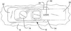
- FIG. 1 ais a perspective view of a privacy shutter in accordance with an embodiment of the present invention, shown in a closed or privacy position;
- FIG. 1 bis a perspective view of the privacy shutter of FIG. 1 a , shown in the open or use position;
- FIG. 2 ais a front view of the privacy shutter of FIG. 1 a , shown in the closed or privacy position on a computer;
- FIG. 2 bis a front view of the privacy shutter of FIG. 1 a , shown in the open or use position;
- FIG. 3is a schematic view of the privacy shutter of FIG. 1 a , shown in the open or use position on a computer;
- FIG. 4 ais a front view of the privacy shutter of FIG. 1 a , shown in the closed or privacy position;
- FIG. 4 bis a side view of the privacy shutter of FIG. 1 a , shown in the closed or privacy position;
- FIG. 4 cis an end view of the privacy shutter of FIG. 1 a , shown in the closed or privacy position;
- FIG. 4 dis an opposite end view of the privacy shutter of FIG. 1 a , shown in the closed or privacy position;
- FIG. 4 eis a rear view of the privacy shutter of FIG. 1 a , shown in the closed or privacy position;
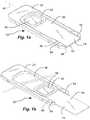
- FIG. 5 ais a perspective view of a frame of the privacy shutter of FIG. 1 a;
- FIG. 5 bis a front view of the frame of the privacy shutter of FIG. 1 a;
- FIG. 5 cis a rear view of the frame of the privacy shutter of FIG. 1 a;
- FIG. 5 dis a rear perspective view of the frame of the privacy shutter of FIG. 1 a;
- FIG. 6 ais a perspective view of a slider of the privacy shutter of FIG. 1 a;
- FIG. 6 bis a front view of the slider of the privacy shutter of FIG. 1 a;
- FIG. 6 cis a rear view of the slider of the privacy shutter of FIG. 1 a;
- FIG. 6 dis a rear perspective view of the slider of the privacy shutter of FIG. 1 a;
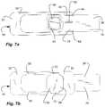
- FIG. 7 ais a front view of the privacy shutter of FIG. 1 a , shown in the closed or privacy position;
- FIG. 7 bis a rear view of the privacy shutter of FIG. 1 a , shown in the open or use position.
- ⁇As used herein, the terms “computer” and “computer device” are used interchangeably to refer to a computer, such as a laptop computer, tablet computer, desktop computer, or cellular phone, with a camera.
- businessis used broadly and interchangeably herein to refer to an organization that provides a product or a service.
- the business, company or organizationcan have a name, logo, slogan, trademark, service mark, etc. that is capable of identifying and/or distinguishing the business or company, or product or service, or both, or can otherwise be utilized to market, promote, and/or brand the business or company, or product or service, or both.
- a privacy shutteris presented that can be adhered to a surface of a computer surrounding a camera lens of a computer camera.
- the privacy shuttercan selectively cover and expose the camera lens.
- the shuttercan be thin to accommodate a thin gap between a display and a keyboard of a laptop computer when folded.
- the shuttercan be small to accommodate the limited space surrounding the camera lens.
- the shuttercan present a surface for indicium.
- the shuttercan be configured to present the indicium at all times without covering or obscuring the indicium.
- a privacy shutterindicated generally at 10 , in an example implementation in accordance with the invention is shown for selectively covering and exposing a camera lens 14 on a computer device 18 .
- the privacy shutter 10has a frame 22 and a slider 26 carried by the frame.
- the frame 22has an inner side 30 disposed against, and at least a portion of affixed to, a surface surrounding the camera lens 14 on the computer device 18 .
- the frame 22has an outer side 34 opposite the inner side 30 .
- An aperture 38is disposed in the frame and circumscribed by the frame 22 .
- the aperture 38can be aligned with and can circumscribe the camera lens 14 .
- the frame 22can be thin.
- the frame 22 and the shutter 10can have a thickness between the inner and outer sides less than 0.1 inches (2.5 mm) in one aspect, less than 0.08 inches (2 mm) in another aspect, and approximately 0.06 inches (1.5 mm) in another aspect.
- the frame 22 and the shutter 10can be elongated, and can have a length along a longitudinal axis 40 longer than a width thereof.
- a channel 42is disposed in the outer side 34 of the frame 22 and extends from the aperture 38 to a perimeter 44 of the frame.
- the channel 42has opposite open ends with one open end in the aperture 38 and another open end in the perimeter 44 .
- the channel 42can be formed in a perimeter side of the frame 22 , at one end of the frame with respect to the longitudinal axis 40 .
- the channel 42can be aligned with a long axis or longitudinal axis 40 of the frame 22 .
- the channel 42has an outer opening 46 in the outer side 34 or the frame 22 , and an inner cavity 50 in the frame 22 .
- the outer opening 46faces outwardly along with the outer side 34 .
- the outer opening 46is narrower than the inner cavity 50 , forming opposite lips 54 extending over the inner cavity 50 of the channel 42 .
- the outer opening 46has a width between the lips 54 , and orthogonal to the longitudinal axis 40 .
- the width of the outer opening 46can be less than a width of the aperture 38 of the frame 22 , with the width of the aperture 38 parallel with the width of the outer opening 46 , and orthogonal to the longitudinal axis 40 .
- the lips 54 of the channel 42can form opposing grooves 56 ( FIGS. 4 c and 5 a ) that face one another across the channel 42 .
- the grooves 56extend along a length of the channel 42 parallel with the longitudinal axis 40 and between the aperture 38 and the perimeter side, but not along the aperture 38 itself.
- a pair of slots 58are formed in the inner side 30 of the frame 22 on opposite sides of the aperture 38 , forming a track.
- the slots 58are open to the aperture 38 and extend along opposite sides thereof along a length of the slot 38 parallel with the longitudinal axis 40 .
- the slots 58can have a cross-sectional profile, perpendicular to the longitudinal axis 40 , with one side and a bottom formed by the frame 22 , and the other side formed by the surface of the computer device 18 .
- the slots 58can oppose one another and can have openings that face one another across the aperture 38 .
- the slider 26is carried by the frame 22 and slidably with respect to the aperture 38 and the frame 22 .
- the slider 26has a head 62 slidably disposed in the aperture 38 of the frame 22 .
- the head 62remains in the aperture 38 as it slides therein, and as the slider 26 slides.
- the head 62 or the slider 26has an inner surface 66 that can be flush with the inner side 30 of the frame 22 , and that can abut to and slide against the surface of the computer device 18 .
- a pair of tabs 70extend from opposite sides of the head 62 and into the pair of slots 58 , respectively, as shown in FIG. 4 e .
- the pair of tabs 70is slidable in the pair of slots 58 as the slider 26 slides.
- the pair of tabs 70are held between the frame 22 and the computer device 18 .
- the pair of tabs 70retain the head 62 in the aperture 38 , and resist the head 62 from coming out of the aperture 38 .
- the slider 26has a flap 74 that extends from the head 62 and into the channel 42 of the frame 22 .
- the flap 74is slidable in the channel 42 and between the lips 54 and in the grooves 56 , with the lips 54 and the grooves 56 retaining the flap 74 in the channel 42 .
- the flap 74 and the slider 26have an outer surface 78 that is exposed in the outer opening 46 of the channel 42 , and between the lips 54 of the channel.
- the flap 74or at least a portion thereof, remains in the channel 42 , and over a portion of the frame 22 , while a portion of the slider 26 or the flap 74 can extend out of the aperture 38 and beyond the perimeter 44 of the frame 22 .
- the slider 26is held at two separate and distinct points, namely the head 62 being held in the aperture 38 with the tabs 70 thereof held in the slots 58 , and the flap 74 held in the channel 42 and in the grooves 56 thereof.
- the slider 26can be held firmly and sliding motion of the slider can be smooth and binding resisted due to the two points of retention.
- the slider 26is held from opposite sides of the frame 22 with the tabs 70 in the slots 58 on the back side and the flap 74 I the grooves 56 on the front side.
- the flap 74 of the slider 26is held only by the lips 54 and in the grooves 56 , and not in the aperture 38 , to facilitate assembly of the slider 26 with the frame 22 .
- the flap 74 of the slider 26can be inserted into the aperture 38 from the back and into the grooves 56 , and the head 62 inserted into the aperture 38 with the tabs 70 in the slots 58 , because the width of the channel 42 between the lips 54 are narrower than the width of the aperture 38 , and because the grooves 56 only extend along the channel 42 , and not into the aperture 38 .
- the slider 26is slidable with respect to the frame 22 and the aperture 38 between open and closed positions.
- the slider 22In the closed position, the slider 22 is disposed across the aperture 38 of the frame 22 , to be disposed over the camera lens 14 of the computer device 18 , as shown in FIG. 2 a .
- the slider 22can be disposed across the entire aperture 38 , and can span the aperture 38 , as shown.
- the slider 22can be disposed across a portion of the aperture 38 of the frame 22 corresponding to the camera lens 14 of the computer device 18 .
- the head 62is disposed in the aperture 38 of the frame 22 in the closed position.
- the flap 74is disposed in the aperture 38 of the frame 22 in the closed position, while the remaining portion of the flap 74 is disposed in the channel 42 .
- the slidercan be characterized as being disposed in the aperture in the closed position.
- the entire slider 26including the head 62 and the flap 74 , can be contained within a perimeter of the frame 22 in the closed position, thus reducing the risk of a portion of the slider becoming snagged during use.
- the head 62remains in the aperture 38 in both the open and the closed positions.
- a distal end of the flap 74opposite the head 62 , is disposed in the channel 46 and over a portion of the frame 22 in the closed position.
- the slider 22 and the flap 74 and the head 62expose the aperture 38 of the frame 22 , to expose the camera lens 14 of the computer device 18 , as shown in FIG. 2 b .
- a portion of the slider 26 or the flap 74extends beyond the perimeter 44 of the frame 22 in the open position.
- the outer opening 46 of the channel 42 between the lips 54exposes the outer surface 78 of the slider 26 and the flap 74 in the opened position, as well as the closed position.
- indicium 82such as a logo, can be disposed on the outer surface 78 of the slider 26 and the flap 74 .
- the indicium 82is exposed in both the open and the closed positions of the slider 26 .
- the indicium 82can be disposed between the lips 54 , and over the channel 42 of the frame 22 in the open position of the slider 26 and the flap 74 , as shown in FIG. 2 b .
- the indicium 82can be indicative of or represent a business, a product, or both.
- the shutter 10can be used as a promotional product.
- the head 62can be a raised head and can extend from the outer surface 78 of the slider 26 and the flap 74 .
- the head 62can have an outer surface 84 ( FIG. 4 a ) substantially flush with the outer side 34 of the frame 22 .
- the head 62can have a thickness substantially the same as the thickness of the frame 22 .
- An indentation 86can be formed in the head 62 or outer surface 84 thereof to form a finger recess to facilitate engaging the slider 26 and sliding the slider back and forth. Because the inner surface 66 of the head 62 can abut to the surface of the computer device 18 , force applied to the head 62 or the indentation 86 can bear against the computer device 18 and not the frame 22 .
- the head 62 and the finger recess or indentation 86is contained within a perimeter of the frame 22 .
- a perimeter of the head 62can circumscribe the indentation 86 .
- the head 62is disposed in the aperture 38 of the frame 22 , and slidable therein.
- the head 62has a width orthogonal to the longitudinal axis 40 that spans the width of the aperture 38 of the frame 22 .
- the width of the outer opening 46 of the channel 42 of the frame 22is less than the width of the aperture 38 of the frame 22 , and the head 62 .
- the head 62abuts to the pair of lips 54 and the open end of the channel 46 in the aperture 38 in the open position to retain the slider 26 in the frame 22 .
- an adhesive 90is disposed on the inner side 30 of the frame 22 to adhere the frame 22 to the surface surrounding the camera lens 14 on the computer device 18 .
- the adhesive 90is disposed on opposite sides of the aperture 39 .
- the adhesive 90is disposed on the inner side 30 of the frame 22 opposite the channel 42 .
Landscapes
- Physics & Mathematics (AREA)
- General Physics & Mathematics (AREA)
- Engineering & Computer Science (AREA)
- Computer Hardware Design (AREA)
- Theoretical Computer Science (AREA)
- Human Computer Interaction (AREA)
- General Engineering & Computer Science (AREA)
- Studio Devices (AREA)
Abstract
Description
Claims (20)
Priority Applications (2)
| Application Number | Priority Date | Filing Date | Title |
|---|---|---|---|
| US15/837,778US10761404B2 (en) | 2017-12-11 | 2017-12-11 | Privacy shutter for computer camera |
| US16/399,306US11054719B2 (en) | 2017-12-11 | 2019-04-30 | Privacy shutter for computer camera with finger grip |
Applications Claiming Priority (1)
| Application Number | Priority Date | Filing Date | Title |
|---|---|---|---|
| US15/837,778US10761404B2 (en) | 2017-12-11 | 2017-12-11 | Privacy shutter for computer camera |
Related Child Applications (1)
| Application Number | Title | Priority Date | Filing Date |
|---|---|---|---|
| US16/399,306Continuation-In-PartUS11054719B2 (en) | 2017-12-11 | 2019-04-30 | Privacy shutter for computer camera with finger grip |
Publications (2)
| Publication Number | Publication Date |
|---|---|
| US20190179212A1 US20190179212A1 (en) | 2019-06-13 |
| US10761404B2true US10761404B2 (en) | 2020-09-01 |
Family
ID=66696692
Family Applications (1)
| Application Number | Title | Priority Date | Filing Date |
|---|---|---|---|
| US15/837,778Active2038-11-08US10761404B2 (en) | 2017-12-11 | 2017-12-11 | Privacy shutter for computer camera |
Country Status (1)
| Country | Link |
|---|---|
| US (1) | US10761404B2 (en) |
Cited By (14)
| Publication number | Priority date | Publication date | Assignee | Title |
|---|---|---|---|---|
| US10884459B1 (en)* | 2019-09-26 | 2021-01-05 | Chicony Electronics Co., Ltd. | Electronic device and moving module thereof |
| USD909454S1 (en)* | 2019-06-19 | 2021-02-02 | 1Coverme Limited | Camera cover |
| US11079657B1 (en)* | 2020-06-10 | 2021-08-03 | Inventec (Pudong) Technology Corporation | Display module |
| US20210273419A1 (en)* | 2018-07-20 | 2021-09-02 | Brilliant Home Technology, Inc. | Shutter mechanism for an electronic device |
| US11240438B1 (en)* | 2021-05-10 | 2022-02-01 | Dell Products L.P. | Information handling system camera with automated tilt, pan and shutter functionality |
| US20220171258A1 (en)* | 2020-11-30 | 2022-06-02 | Viewsonic International Corporation | Webcam module |
| TWI789697B (en)* | 2021-01-27 | 2023-01-11 | 仁寶電腦工業股份有限公司 | Camera module |
| US20240012454A1 (en)* | 2021-03-24 | 2024-01-11 | Panasonic Intellectual Property Management Co., Ltd. | Electronic device |
| US12101539B2 (en) | 2023-01-05 | 2024-09-24 | Dell Products L.P. | Information handling system camera shutter with secondary security by power removal |
| US12155939B2 (en) | 2023-01-05 | 2024-11-26 | Dell Products L.P. | Information handling system floating camera shutter with adaptive height |
| US12181774B2 (en) | 2023-01-05 | 2024-12-31 | Dell Products L.P. | Information handling system electromechanical camera shutter with plural apertures |
| US12212833B2 (en) | 2023-01-05 | 2025-01-28 | Dell Products L.P. | Information handling system camera shutter with external fail safe |
| US12284449B2 (en) | 2023-01-05 | 2025-04-22 | Dell Products L.P. | Information handling system camera shutter with audio feedback of position change |
| USD1094521S1 (en)* | 2022-07-12 | 2025-09-23 | Flashbay Electronics Hong Kong Limited | Webcam cover |
Families Citing this family (21)
| Publication number | Priority date | Publication date | Assignee | Title |
|---|---|---|---|---|
| USD926182S1 (en)* | 2017-01-30 | 2021-07-27 | Kameron Miller | Cell phone privacy cover |
| US11054719B2 (en) | 2017-12-11 | 2021-07-06 | Handstands Promo, Llc | Privacy shutter for computer camera with finger grip |
| US11143937B2 (en)* | 2017-12-15 | 2021-10-12 | Hewlett-Packard Development Company, L.P. | Shutter assemblies for electronic devices |
| CN208014265U (en)* | 2017-12-30 | 2018-10-26 | 邓志军 | Display screen peep-proof device and display screen screen protective device supporting member |
| WO2019156683A1 (en)* | 2018-02-12 | 2019-08-15 | Hewlett-Packard Development Company, L.P. | View shutters with slider magnets |
| US20190272005A1 (en)* | 2018-03-05 | 2019-09-05 | Targus International Llc | Display cover with webcam cover |
| US11054720B1 (en) | 2018-05-01 | 2021-07-06 | Handstands Promo, Llc | Sliding miniature lens cover |
| DE102018112763B3 (en)* | 2018-05-29 | 2019-06-19 | Yusuf Güzel | Retrofit Ausspähschutz |
| USD940121S1 (en)* | 2018-06-06 | 2022-01-04 | Ye Lu | Mobile phone case |
| US20190391464A1 (en)* | 2018-06-21 | 2019-12-26 | Adam Mancuso | Shutter device for a mobile device |
| TWI768162B (en)* | 2018-12-12 | 2022-06-21 | 群光電子股份有限公司 | Electronic device and privacy protection module thereof |
| DE212020000722U1 (en) | 2019-09-18 | 2022-04-26 | Gopro, Inc. | door assemblies for imaging devices |
| US12066748B2 (en) | 2019-09-18 | 2024-08-20 | Gopro, Inc. | Door assemblies for image capture devices |
| WO2022000417A1 (en) | 2020-07-02 | 2022-01-06 | Gopro, Inc. | Removable battery door assemblies for image capture devices |
| USD1050227S1 (en) | 2020-08-14 | 2024-11-05 | Gopro, Inc. | Camera door |
| USD1066462S1 (en)* | 2021-02-12 | 2025-03-11 | Gopro, Inc. | Camera door |
| USD961575S1 (en)* | 2022-01-19 | 2022-08-23 | GuangDong ReDian Electronic Technology Co., Ltd. | Case for mobile telephone |
| USD1061682S1 (en) | 2022-08-04 | 2025-02-11 | Gopro, Inc. | Camera door |
| USD1052569S1 (en)* | 2023-11-17 | 2024-11-26 | Shenzhen Lanhe Technologies Co., Ltd. | Case for electronic device |
| USD1028958S1 (en)* | 2023-12-11 | 2024-05-28 | Foshan xiongda electronic technology co., ltd. | Phone case |
| USD1038102S1 (en)* | 2024-03-11 | 2024-08-06 | Pengtao ZHANG | Case for mobile telephone |
Citations (29)
| Publication number | Priority date | Publication date | Assignee | Title |
|---|---|---|---|---|
| US20110182029A1 (en) | 2010-01-22 | 2011-07-28 | Asustek Computer Inc. | Notebook Computer Device with Image Capture Module |
| USD669112S1 (en) | 2011-02-22 | 2012-10-16 | Gust Marketing, L.L.C. | Webcam cover |
| US8471956B2 (en) | 2009-10-29 | 2013-06-25 | Bornbex Handels- Und Vertriebs Gmbh & Co. Kg | Closure device for an image capture facility |
| USD708657S1 (en) | 2011-02-22 | 2014-07-08 | Sol Pals, Llc | Webcam cover |
| US20140220269A1 (en) | 2013-02-05 | 2014-08-07 | Anthony Ogufere Ogufere | Computer webcam lens blocker assembly |
| US20150009399A1 (en) | 2013-07-06 | 2015-01-08 | Karl S. Jonsson | Webcam privacy shield |
| US20150015777A1 (en) | 2013-07-09 | 2015-01-15 | Lenovo (Singapore) Pte. Ltd. | Control flap |
| USD721396S1 (en) | 2013-11-20 | 2015-01-20 | Sol Pals, Llc | Webcam cover |
| US20150070575A1 (en) | 2013-09-11 | 2015-03-12 | Podo Labs, Inc. | Digital camera utilizing surface for temporary mounting |
| US20160088264A1 (en) | 2014-09-19 | 2016-03-24 | Andrew J. Freeze | Security Door for Electronic Communication Devices |
| US20160161830A1 (en) | 2013-06-24 | 2016-06-09 | Jose Manuel Gonzalez Sanchez | Security Cover on Web Cameras with Parental Control |
| USD763843S1 (en) | 2015-03-13 | 2016-08-16 | Sol Pals, Llc | Webcam cover |
| USD782562S1 (en) | 2015-12-15 | 2017-03-28 | Sol Pals, Llc | Webcam cover |
| USD793465S1 (en) | 2014-12-23 | 2017-08-01 | Intel Corporation | Movable camera module for portable electronic device |
| USD794108S1 (en) | 2015-05-26 | 2017-08-08 | Samsung Electronics Co., Ltd. | Cover for camera |
| USD794645S1 (en) | 2016-01-12 | 2017-08-15 | Nancy Erlick | Device cover |
| US20170329206A1 (en) | 2016-05-13 | 2017-11-16 | Sol Pals, Llc | Camera obstructing device |
| US20170371128A1 (en) | 2016-06-27 | 2017-12-28 | Ming-Jui LI | Disposable lens applied to electronic operation device for recognition |
| USD807947S1 (en) | 2016-06-10 | 2018-01-16 | Sol Pals, Llc | Sliding webcam cover |
| USD808457S1 (en) | 2016-05-13 | 2018-01-23 | Sol Pals, Llc | Webcam cover |
| USD810180S1 (en) | 2016-05-13 | 2018-02-13 | Sol Pals, Llc | Webcam cover |
| US20180059510A1 (en)* | 2016-05-13 | 2018-03-01 | Sol Pals, Llc | Camera obstructing device |
| USD816149S1 (en) | 2016-09-22 | 2018-04-24 | Sun Coast Merchandise Corp. | Webcam cover |
| US20180123631A1 (en) | 2016-10-31 | 2018-05-03 | Tamim Mohammad Hessabi | (Smartphone) Camera Cover Case Specifications |
| US10015296B1 (en) | 2017-06-21 | 2018-07-03 | Handstands Promo, Llc | Lens cover |
| US10070021B1 (en) | 2017-06-06 | 2018-09-04 | Ryan Rolle | Camera-covering accessory for a computer |
| USD836154S1 (en) | 2016-05-13 | 2018-12-18 | C-Slide Holdings, Llc | Webcam cover with stone element |
| USD837279S1 (en) | 2014-05-02 | 2019-01-01 | Kaseem George Penn | Camera block apparatus |
| USD839946S1 (en) | 2017-01-03 | 2019-02-05 | Secuferro B.V. | Webcam cover |
- 2017
- 2017-12-11USUS15/837,778patent/US10761404B2/enactiveActive
Patent Citations (32)
| Publication number | Priority date | Publication date | Assignee | Title |
|---|---|---|---|---|
| US8471956B2 (en) | 2009-10-29 | 2013-06-25 | Bornbex Handels- Und Vertriebs Gmbh & Co. Kg | Closure device for an image capture facility |
| US20110182029A1 (en) | 2010-01-22 | 2011-07-28 | Asustek Computer Inc. | Notebook Computer Device with Image Capture Module |
| USD669112S1 (en) | 2011-02-22 | 2012-10-16 | Gust Marketing, L.L.C. | Webcam cover |
| USD708657S1 (en) | 2011-02-22 | 2014-07-08 | Sol Pals, Llc | Webcam cover |
| US20140220269A1 (en) | 2013-02-05 | 2014-08-07 | Anthony Ogufere Ogufere | Computer webcam lens blocker assembly |
| US20160161830A1 (en) | 2013-06-24 | 2016-06-09 | Jose Manuel Gonzalez Sanchez | Security Cover on Web Cameras with Parental Control |
| US20150009399A1 (en) | 2013-07-06 | 2015-01-08 | Karl S. Jonsson | Webcam privacy shield |
| US20150015777A1 (en) | 2013-07-09 | 2015-01-15 | Lenovo (Singapore) Pte. Ltd. | Control flap |
| US20150070575A1 (en) | 2013-09-11 | 2015-03-12 | Podo Labs, Inc. | Digital camera utilizing surface for temporary mounting |
| USD721396S1 (en) | 2013-11-20 | 2015-01-20 | Sol Pals, Llc | Webcam cover |
| USD837279S1 (en) | 2014-05-02 | 2019-01-01 | Kaseem George Penn | Camera block apparatus |
| US20160088264A1 (en) | 2014-09-19 | 2016-03-24 | Andrew J. Freeze | Security Door for Electronic Communication Devices |
| USD793465S1 (en) | 2014-12-23 | 2017-08-01 | Intel Corporation | Movable camera module for portable electronic device |
| USD763843S1 (en) | 2015-03-13 | 2016-08-16 | Sol Pals, Llc | Webcam cover |
| USD794108S1 (en) | 2015-05-26 | 2017-08-08 | Samsung Electronics Co., Ltd. | Cover for camera |
| USD782562S1 (en) | 2015-12-15 | 2017-03-28 | Sol Pals, Llc | Webcam cover |
| USD794645S1 (en) | 2016-01-12 | 2017-08-15 | Nancy Erlick | Device cover |
| US20170329206A1 (en) | 2016-05-13 | 2017-11-16 | Sol Pals, Llc | Camera obstructing device |
| USD836154S1 (en) | 2016-05-13 | 2018-12-18 | C-Slide Holdings, Llc | Webcam cover with stone element |
| US10317776B2 (en) | 2016-05-13 | 2019-06-11 | Sol Pals, Llc | Camera obstructing device |
| USD808457S1 (en) | 2016-05-13 | 2018-01-23 | Sol Pals, Llc | Webcam cover |
| USD810180S1 (en) | 2016-05-13 | 2018-02-13 | Sol Pals, Llc | Webcam cover |
| US20180059510A1 (en)* | 2016-05-13 | 2018-03-01 | Sol Pals, Llc | Camera obstructing device |
| USD849123S1 (en) | 2016-05-13 | 2019-05-21 | Sol Pals, Llc | Webcam cover |
| US9829770B1 (en) | 2016-05-13 | 2017-11-28 | Sol Pals, Llc | Camera obstructing device |
| USD807947S1 (en) | 2016-06-10 | 2018-01-16 | Sol Pals, Llc | Sliding webcam cover |
| US20170371128A1 (en) | 2016-06-27 | 2017-12-28 | Ming-Jui LI | Disposable lens applied to electronic operation device for recognition |
| USD816149S1 (en) | 2016-09-22 | 2018-04-24 | Sun Coast Merchandise Corp. | Webcam cover |
| US20180123631A1 (en) | 2016-10-31 | 2018-05-03 | Tamim Mohammad Hessabi | (Smartphone) Camera Cover Case Specifications |
| USD839946S1 (en) | 2017-01-03 | 2019-02-05 | Secuferro B.V. | Webcam cover |
| US10070021B1 (en) | 2017-06-06 | 2018-09-04 | Ryan Rolle | Camera-covering accessory for a computer |
| US10015296B1 (en) | 2017-06-21 | 2018-07-03 | Handstands Promo, Llc | Lens cover |
Non-Patent Citations (2)
| Title |
|---|
| Hit Promotional Products, "#265 Security Webcam Cover", https://www.hitpromo.net/product/show/265/security-webcam-cover as accessed on this date: Dec. 14, 2017. |
| Targus, "Spy Guard Webcam Cover", http://www.targus.com/us/spy-guard-webcam-cover-3-pack-awh012us as accessed on this date: Dec. 14, 2017. |
Cited By (19)
| Publication number | Priority date | Publication date | Assignee | Title |
|---|---|---|---|---|
| US12249813B2 (en) | 2018-07-20 | 2025-03-11 | Brilliant NextGen, Inc. | Shutter mechanism for an electronic device |
| US20210273419A1 (en)* | 2018-07-20 | 2021-09-02 | Brilliant Home Technology, Inc. | Shutter mechanism for an electronic device |
| US11715938B2 (en) | 2018-07-20 | 2023-08-01 | Brilliant Home Technology, Inc | Mounting device with fastener receiving structure |
| US11728628B2 (en)* | 2018-07-20 | 2023-08-15 | Brilliant Home Technology, Inc. | Shutter mechanism for an electronic device |
| USD909454S1 (en)* | 2019-06-19 | 2021-02-02 | 1Coverme Limited | Camera cover |
| US10884459B1 (en)* | 2019-09-26 | 2021-01-05 | Chicony Electronics Co., Ltd. | Electronic device and moving module thereof |
| US11079657B1 (en)* | 2020-06-10 | 2021-08-03 | Inventec (Pudong) Technology Corporation | Display module |
| US20220171258A1 (en)* | 2020-11-30 | 2022-06-02 | Viewsonic International Corporation | Webcam module |
| US12253789B2 (en)* | 2020-11-30 | 2025-03-18 | Viewsonic International Corporation | Webcam module |
| TWI789697B (en)* | 2021-01-27 | 2023-01-11 | 仁寶電腦工業股份有限公司 | Camera module |
| US20240012454A1 (en)* | 2021-03-24 | 2024-01-11 | Panasonic Intellectual Property Management Co., Ltd. | Electronic device |
| US12405633B2 (en)* | 2021-03-24 | 2025-09-02 | Panasonic Intellectual Property Management Co., Ltd. | Electronic device |
| US11240438B1 (en)* | 2021-05-10 | 2022-02-01 | Dell Products L.P. | Information handling system camera with automated tilt, pan and shutter functionality |
| USD1094521S1 (en)* | 2022-07-12 | 2025-09-23 | Flashbay Electronics Hong Kong Limited | Webcam cover |
| US12212833B2 (en) | 2023-01-05 | 2025-01-28 | Dell Products L.P. | Information handling system camera shutter with external fail safe |
| US12181774B2 (en) | 2023-01-05 | 2024-12-31 | Dell Products L.P. | Information handling system electromechanical camera shutter with plural apertures |
| US12155939B2 (en) | 2023-01-05 | 2024-11-26 | Dell Products L.P. | Information handling system floating camera shutter with adaptive height |
| US12284449B2 (en) | 2023-01-05 | 2025-04-22 | Dell Products L.P. | Information handling system camera shutter with audio feedback of position change |
| US12101539B2 (en) | 2023-01-05 | 2024-09-24 | Dell Products L.P. | Information handling system camera shutter with secondary security by power removal |
Also Published As
| Publication number | Publication date |
|---|---|
| US20190179212A1 (en) | 2019-06-13 |
Similar Documents
| Publication | Publication Date | Title |
|---|---|---|
| US10761404B2 (en) | Privacy shutter for computer camera | |
| US7789437B2 (en) | Lockable door assembly of an electronic device | |
| US10003371B1 (en) | Electronic device case comprising sliding camera lens covers | |
| US9901151B2 (en) | Card holder embedded into a mobile device case | |
| US20100206923A1 (en) | Carrying Cases Having Sound Enhancing Capability, For Portable Communication Devices | |
| US11054719B2 (en) | Privacy shutter for computer camera with finger grip | |
| WO2005086764A3 (en) | Data structure with performance descriptors | |
| US20130004012A1 (en) | Electronic tablet device's sound guide cover | |
| EP2398115A1 (en) | A front plate for a socket | |
| US20170159881A1 (en) | Head mounted display housing | |
| KR200470353Y1 (en) | Protection case for smart phone | |
| US20060261711A1 (en) | Computer bezel | |
| US20090045079A1 (en) | Optical casing with skylight arrangement | |
| US20170341455A1 (en) | Single booster binder mechanism | |
| USD914687S1 (en) | Notebook computer | |
| US7845381B2 (en) | Adhesive tape cutter | |
| KR200478502Y1 (en) | Hand phone protection case for camera protection | |
| KR102460208B1 (en) | Card storage type mobile phone case | |
| JP4826972B2 (en) | Cover unit for storage unit | |
| US20060108403A1 (en) | Expanding file holder having a window | |
| CN209787221U (en) | rebound SIM card slot | |
| KR200442456Y1 (en) | Slider assembly for digital camera lens cover | |
| CN207939616U (en) | A kind of protection cap for digital electronic goods camera | |
| CN219699260U (en) | Writing case with card punching function | |
| US8109461B2 (en) | Film transfer device with slidable protection cap |
Legal Events
| Date | Code | Title | Description |
|---|---|---|---|
| AS | Assignment | Owner name:HANDSTANDS PROMO, LLC, UTAH Free format text:ASSIGNMENT OF ASSIGNORS INTEREST;ASSIGNOR:LEIMER, STEFAN;REEL/FRAME:044356/0543 Effective date:20171208 | |
| FEPP | Fee payment procedure | Free format text:ENTITY STATUS SET TO UNDISCOUNTED (ORIGINAL EVENT CODE: BIG.); ENTITY STATUS OF PATENT OWNER: SMALL ENTITY | |
| FEPP | Fee payment procedure | Free format text:ENTITY STATUS SET TO SMALL (ORIGINAL EVENT CODE: SMAL); ENTITY STATUS OF PATENT OWNER: SMALL ENTITY | |
| STPP | Information on status: patent application and granting procedure in general | Free format text:DOCKETED NEW CASE - READY FOR EXAMINATION | |
| AS | Assignment | Owner name:FIDUS INVESTMENT CORPORATION, ILLINOIS Free format text:SECURITY INTEREST;ASSIGNOR:HANDSTANDS PROMO, LLC;REEL/FRAME:047848/0248 Effective date:20181221 | |
| AS | Assignment | Owner name:CRESCENT DIRECT LENDING, LLC, AS AGENT, MASSACHUSE Free format text:SECURITY INTEREST;ASSIGNOR:HANDSTANDS PROMO, LLC;REEL/FRAME:048040/0367 Effective date:20181221 Owner name:CRESCENT DIRECT LENDING, LLC, AS AGENT, MASSACHUSETTS Free format text:SECURITY INTEREST;ASSIGNOR:HANDSTANDS PROMO, LLC;REEL/FRAME:048040/0367 Effective date:20181221 | |
| STPP | Information on status: patent application and granting procedure in general | Free format text:NON FINAL ACTION MAILED | |
| STPP | Information on status: patent application and granting procedure in general | Free format text:NOTICE OF ALLOWANCE MAILED -- APPLICATION RECEIVED IN OFFICE OF PUBLICATIONS | |
| STPP | Information on status: patent application and granting procedure in general | Free format text:PUBLICATIONS -- ISSUE FEE PAYMENT VERIFIED | |
| STCF | Information on status: patent grant | Free format text:PATENTED CASE | |
| AS | Assignment | Owner name:HANDSTANDS PROMO, LLC, UTAH Free format text:CORRECTIVE ASSIGNMENT TO CORRECT THE ASSIGNEE'S ENTITY NAME IN THE ASSIGNMENT DOCUMENT PREVIOUSLY RECORDED AT REEL: 044356 FRAME: 0543. ASSIGNOR(S) HEREBY CONFIRMS THE ASSIGNMENT;ASSIGNOR:LEIMER, STEFAN;REEL/FRAME:056062/0003 Effective date:20171208 | |
| AS | Assignment | Owner name:CRESCENT AGENCY SERVICES, LLC, MASSACHUSETTS Free format text:SECURITY INTEREST;ASSIGNORS:WEBB BUSINESS PROMOTIONS, LLC;BEST PROMOTIONS, LLC;HANDSTANDS PROMO, LLC;AND OTHERS;REEL/FRAME:063754/0633 Effective date:20230425 | |
| AS | Assignment | Owner name:FIDUS INVESTMENT CORPORATION, ILLINOIS Free format text:SECURITY INTEREST;ASSIGNORS:WEBB BUSINESS PROMOTIONS, LLC;BEST PROMOTIONS, LLC;HANDSTANDS PROMO, LLC;AND OTHERS;REEL/FRAME:063470/0871 Effective date:20230425 Owner name:HANDSTANDS PROMO, LLC, UTAH Free format text:RELEASE BY SECURED PARTY;ASSIGNOR:FIDUS INVESTMENT CORPORATION;REEL/FRAME:063448/0441 Effective date:20230425 | |
| AS | Assignment | Owner name:WEBB BUSINESS PROMOTIONS, INCORPORATED, MINNESOTA Free format text:RELEASE BY SECURED PARTY;ASSIGNOR:CRESCENT DIRECT LENDING, LLC;REEL/FRAME:063473/0865 Effective date:20230425 Owner name:HANDSSTANDS PROMO, LLC, UTAH Free format text:RELEASE BY SECURED PARTY;ASSIGNOR:CRESCENT DIRECT LENDING, LLC;REEL/FRAME:063473/0865 Effective date:20230425 Owner name:BEST PROMOTIONS, LLC, NEW YORK Free format text:RELEASE BY SECURED PARTY;ASSIGNOR:CRESCENT DIRECT LENDING, LLC;REEL/FRAME:063473/0865 Effective date:20230425 Owner name:HUB PEN COMPANY, LLC, MASSACHUSETTS Free format text:RELEASE BY SECURED PARTY;ASSIGNOR:CRESCENT DIRECT LENDING, LLC;REEL/FRAME:063473/0865 Effective date:20230425 | |
| MAFP | Maintenance fee payment | Free format text:PAYMENT OF MAINTENANCE FEE, 4TH YR, SMALL ENTITY (ORIGINAL EVENT CODE: M2551); ENTITY STATUS OF PATENT OWNER: SMALL ENTITY Year of fee payment:4 |