US10760731B2 - Arm-supporting structure - Google Patents
Arm-supporting structureDownload PDFInfo
- Publication number
- US10760731B2 US10760731B2US15/941,226US201815941226AUS10760731B2US 10760731 B2US10760731 B2US 10760731B2US 201815941226 AUS201815941226 AUS 201815941226AUS 10760731 B2US10760731 B2US 10760731B2
- Authority
- US
- United States
- Prior art keywords
- upper support
- support
- adjusting means
- lower support
- arm connector
- Prior art date
- Legal status (The legal status is an assumption and is not a legal conclusion. Google has not performed a legal analysis and makes no representation as to the accuracy of the status listed.)
- Active, expires
Links
- 230000007246mechanismEffects0.000claimsdescription10
- 238000013459approachMethods0.000description2
- 230000001174ascending effectEffects0.000description2
- 230000009286beneficial effectEffects0.000description1
- 230000006835compressionEffects0.000description1
- 238000007906compressionMethods0.000description1
- 230000007423decreaseEffects0.000description1
- 230000003247decreasing effectEffects0.000description1
- 230000007812deficiencyEffects0.000description1
- 230000000694effectsEffects0.000description1
- 238000009434installationMethods0.000description1
- 230000007774longtermEffects0.000description1
- 238000003754machiningMethods0.000description1
Images


Classifications
- F—MECHANICAL ENGINEERING; LIGHTING; HEATING; WEAPONS; BLASTING
- F16—ENGINEERING ELEMENTS AND UNITS; GENERAL MEASURES FOR PRODUCING AND MAINTAINING EFFECTIVE FUNCTIONING OF MACHINES OR INSTALLATIONS; THERMAL INSULATION IN GENERAL
- F16M—FRAMES, CASINGS OR BEDS OF ENGINES, MACHINES OR APPARATUS, NOT SPECIFIC TO ENGINES, MACHINES OR APPARATUS PROVIDED FOR ELSEWHERE; STANDS; SUPPORTS
- F16M11/00—Stands or trestles as supports for apparatus or articles placed thereon ; Stands for scientific apparatus such as gravitational force meters
- F—MECHANICAL ENGINEERING; LIGHTING; HEATING; WEAPONS; BLASTING
- F16—ENGINEERING ELEMENTS AND UNITS; GENERAL MEASURES FOR PRODUCING AND MAINTAINING EFFECTIVE FUNCTIONING OF MACHINES OR INSTALLATIONS; THERMAL INSULATION IN GENERAL
- F16M—FRAMES, CASINGS OR BEDS OF ENGINES, MACHINES OR APPARATUS, NOT SPECIFIC TO ENGINES, MACHINES OR APPARATUS PROVIDED FOR ELSEWHERE; STANDS; SUPPORTS
- F16M13/00—Other supports for positioning apparatus or articles; Means for steadying hand-held apparatus or articles
- F16M13/02—Other supports for positioning apparatus or articles; Means for steadying hand-held apparatus or articles for supporting on, or attaching to, an object, e.g. tree, gate, window-frame, cycle
- F16M13/022—Other supports for positioning apparatus or articles; Means for steadying hand-held apparatus or articles for supporting on, or attaching to, an object, e.g. tree, gate, window-frame, cycle repositionable
- F—MECHANICAL ENGINEERING; LIGHTING; HEATING; WEAPONS; BLASTING
- F16—ENGINEERING ELEMENTS AND UNITS; GENERAL MEASURES FOR PRODUCING AND MAINTAINING EFFECTIVE FUNCTIONING OF MACHINES OR INSTALLATIONS; THERMAL INSULATION IN GENERAL
- F16F—SPRINGS; SHOCK-ABSORBERS; MEANS FOR DAMPING VIBRATION
- F16F9/00—Springs, vibration-dampers, shock-absorbers, or similarly-constructed movement-dampers using a fluid or the equivalent as damping medium
- F16F9/02—Springs, vibration-dampers, shock-absorbers, or similarly-constructed movement-dampers using a fluid or the equivalent as damping medium using gas only or vacuum
- F16F9/0209—Telescopic
- F16F9/0245—Means for adjusting the length of, or for locking, the spring or dampers
- F—MECHANICAL ENGINEERING; LIGHTING; HEATING; WEAPONS; BLASTING
- F16—ENGINEERING ELEMENTS AND UNITS; GENERAL MEASURES FOR PRODUCING AND MAINTAINING EFFECTIVE FUNCTIONING OF MACHINES OR INSTALLATIONS; THERMAL INSULATION IN GENERAL
- F16F—SPRINGS; SHOCK-ABSORBERS; MEANS FOR DAMPING VIBRATION
- F16F9/00—Springs, vibration-dampers, shock-absorbers, or similarly-constructed movement-dampers using a fluid or the equivalent as damping medium
- F16F9/32—Details
- F16F9/54—Arrangements for attachment
- F—MECHANICAL ENGINEERING; LIGHTING; HEATING; WEAPONS; BLASTING
- F16—ENGINEERING ELEMENTS AND UNITS; GENERAL MEASURES FOR PRODUCING AND MAINTAINING EFFECTIVE FUNCTIONING OF MACHINES OR INSTALLATIONS; THERMAL INSULATION IN GENERAL
- F16M—FRAMES, CASINGS OR BEDS OF ENGINES, MACHINES OR APPARATUS, NOT SPECIFIC TO ENGINES, MACHINES OR APPARATUS PROVIDED FOR ELSEWHERE; STANDS; SUPPORTS
- F16M11/00—Stands or trestles as supports for apparatus or articles placed thereon ; Stands for scientific apparatus such as gravitational force meters
- F16M11/02—Heads
- F16M11/04—Means for attachment of apparatus; Means allowing adjustment of the apparatus relatively to the stand
- F16M11/043—Allowing translations
- F16M11/046—Allowing translations adapted to upward-downward translation movement
- F—MECHANICAL ENGINEERING; LIGHTING; HEATING; WEAPONS; BLASTING
- F16—ENGINEERING ELEMENTS AND UNITS; GENERAL MEASURES FOR PRODUCING AND MAINTAINING EFFECTIVE FUNCTIONING OF MACHINES OR INSTALLATIONS; THERMAL INSULATION IN GENERAL
- F16M—FRAMES, CASINGS OR BEDS OF ENGINES, MACHINES OR APPARATUS, NOT SPECIFIC TO ENGINES, MACHINES OR APPARATUS PROVIDED FOR ELSEWHERE; STANDS; SUPPORTS
- F16M11/00—Stands or trestles as supports for apparatus or articles placed thereon ; Stands for scientific apparatus such as gravitational force meters
- F16M11/02—Heads
- F16M11/04—Means for attachment of apparatus; Means allowing adjustment of the apparatus relatively to the stand
- F16M11/043—Allowing translations
- F16M11/048—Allowing translations adapted to forward-backward translation movement
- F—MECHANICAL ENGINEERING; LIGHTING; HEATING; WEAPONS; BLASTING
- F16—ENGINEERING ELEMENTS AND UNITS; GENERAL MEASURES FOR PRODUCING AND MAINTAINING EFFECTIVE FUNCTIONING OF MACHINES OR INSTALLATIONS; THERMAL INSULATION IN GENERAL
- F16M—FRAMES, CASINGS OR BEDS OF ENGINES, MACHINES OR APPARATUS, NOT SPECIFIC TO ENGINES, MACHINES OR APPARATUS PROVIDED FOR ELSEWHERE; STANDS; SUPPORTS
- F16M11/00—Stands or trestles as supports for apparatus or articles placed thereon ; Stands for scientific apparatus such as gravitational force meters
- F16M11/02—Heads
- F16M11/04—Means for attachment of apparatus; Means allowing adjustment of the apparatus relatively to the stand
- F16M11/06—Means for attachment of apparatus; Means allowing adjustment of the apparatus relatively to the stand allowing pivoting
- F16M11/12—Means for attachment of apparatus; Means allowing adjustment of the apparatus relatively to the stand allowing pivoting in more than one direction
- F16M11/121—Means for attachment of apparatus; Means allowing adjustment of the apparatus relatively to the stand allowing pivoting in more than one direction constituted of several dependent joints
- F—MECHANICAL ENGINEERING; LIGHTING; HEATING; WEAPONS; BLASTING
- F16—ENGINEERING ELEMENTS AND UNITS; GENERAL MEASURES FOR PRODUCING AND MAINTAINING EFFECTIVE FUNCTIONING OF MACHINES OR INSTALLATIONS; THERMAL INSULATION IN GENERAL
- F16F—SPRINGS; SHOCK-ABSORBERS; MEANS FOR DAMPING VIBRATION
- F16F2230/00—Purpose; Design features
- F16F2230/0005—Attachment, e.g. to facilitate mounting onto confer adjustability
- F—MECHANICAL ENGINEERING; LIGHTING; HEATING; WEAPONS; BLASTING
- F16—ENGINEERING ELEMENTS AND UNITS; GENERAL MEASURES FOR PRODUCING AND MAINTAINING EFFECTIVE FUNCTIONING OF MACHINES OR INSTALLATIONS; THERMAL INSULATION IN GENERAL
- F16M—FRAMES, CASINGS OR BEDS OF ENGINES, MACHINES OR APPARATUS, NOT SPECIFIC TO ENGINES, MACHINES OR APPARATUS PROVIDED FOR ELSEWHERE; STANDS; SUPPORTS
- F16M2200/00—Details of stands or supports
- F16M2200/04—Balancing means
- F16M2200/041—Balancing means for balancing rotational movement of the head
- F—MECHANICAL ENGINEERING; LIGHTING; HEATING; WEAPONS; BLASTING
- F16—ENGINEERING ELEMENTS AND UNITS; GENERAL MEASURES FOR PRODUCING AND MAINTAINING EFFECTIVE FUNCTIONING OF MACHINES OR INSTALLATIONS; THERMAL INSULATION IN GENERAL
- F16M—FRAMES, CASINGS OR BEDS OF ENGINES, MACHINES OR APPARATUS, NOT SPECIFIC TO ENGINES, MACHINES OR APPARATUS PROVIDED FOR ELSEWHERE; STANDS; SUPPORTS
- F16M2200/00—Details of stands or supports
- F16M2200/06—Arms
- F16M2200/063—Parallelogram arms
Definitions
- the present disclosurerelates to a bracket, and particularly to an arm-supporting structure.
- brackets for mounting electronic devicesare made to support an electronic device and adjust its height through an arm.
- the arm-structure for height adjustment and supportis achieved as follows.
- One end of both of the upper support and the lower supportis articulated (i.e., in hinge connection) to a base, and the other end thereof is articulated to a connector.
- the baseis provided thereon with a screw which is locked in axial direction but rotatable in a circumferential direction.
- a nut screw that is connected onto the screwis articulated with one end of a gas spring, and the other end of the gas spring is articulated with the upper support, so as to provide support.
- One end of the gas springis made to move up and down by adjusting the screw, so that the length of one side of a triangle formed by the gas spring, the base and the upper support is varied so as to change the elastic support force of the gas spring. Since the fulcrum of the screw and the fulcrum of the gas spring are both located on the base, no matter how the arm is swinging, the fulcrum position of the gas spring remains unchanged. Additionally, there is no connection between the lower support and the gas spring as well as between the lower support and the adjusting means. The lower arm only functions to keep the swivel head horizontal when ascending or descending a device, rather than to support the device. As a result, such an arm-structure has a limited bearing capacity which is normally from 3 kg to 9 kg.
- the present disclosureprovides an arm-supporting structure which is easy to operate, flexible and smooth to adjust, and effort-saving.
- an arm-supporting structureincluding a front arm connector, a rear arm connector, an adjusting means for an upper support and a lower support, and an elastic supporting means, where the front arm connector, the upper support, the rear arm connector and the lower support are articulated (i.e., in hinge connection) sequentially to form a parallelogram structure.
- An upper end and a lower end of the adjusting meansare articulated with the upper support and the lower support, respectively.
- Two ends of the elastic supporting meansare connected to the adjusting means and the upper support, respectively.
- the elastic supporting meansis elastically stretchable in length.
- the adjusting meansis configured to be parallel to the rear arm connector and the front arm connector.
- the adjusting meansincludes a bracket, a slide block and a height adjusting mechanism, where an upper end and a lower end of the bracket are articulated with the upper support and the lower support, respectively, where the slide block can be positioned movably on the bracket along extension direction of the bracket, where the height adjusting means can drive the slide block to move, and where one end of the elastic supporting means is articulated with the slide block.
- the height adjusting meansis an adjusting screw that is rotatably positioned on the bracket in circumferential direction but non-movable in axial direction, where the adjusting screw is in threaded connection with the slide block, and where the upper support is provided thereon with a hollow portion that directly faces a head portion of the adjusting screw.
- two sides of the slide blockare provided with a first articulating shaft that extends along horizontal direction
- one end of the elastic supporting meansis provided with a U-shaped member having two connecting arm
- the connecting arms of the U-shaped memberare sleeved on two sides of the slide block
- each of the connecting arms of the U-shaped memberis provided with a shaft hole
- a bearingis provided in the shaft hole
- the first articulating shaft on the two sidewalls of the slide blockare inserted into the bearings.
- the elastic supporting meansis provided thereon with a stud that extends in an axial direction of the elastic supporting means, where the U-shaped member is provided thereon with a threaded hole, and the stud on the elastic supporting means is in threaded connection with the threaded hole on the U-shaped member.
- the elastic supporting meansis a gas spring.
- the two sidewalls of an upper end of the adjusting meansare each provided with a second articulating shaft that extends in a horizontal direction, where inner side surfaces of the upper support are provided thereon with opening slots, where the second articulating shafts are rotatably inserted into the opening slots of the upper support, where two sidewalls at a lower end of the adjusting means are each provided with a threaded connecting hole that extends axially in the horizontal direction, where two sidewalls at one end of the lower support are each provided with a through-hole, and a connecting screw is further provided, with the connecting screw being configured to pass (or penetrate) through the through-holes in the two sidewalls at the one end of the lower support and being in threaded connection with the threaded connecting holes on the adjusting means.
- each of the opening slots on the upper supportis an elongated opening slot structure that is perpendicular to the inner side surfaces of the upper support, and where opening portions of the opening slots at the inner side surfaces are each provided with a chamfer structure.
- the upper support and the lower supportare U-shaped structures with openings of the U-shaped structures opposing to each other, where sidewalls at two ends of the upper support and sidewalls at two ends of the lower support are each configured to have an arc-shaped end face, where the front arm connector and the rear arm connector are respectively inserted into interiors of the two ends of the upper support and the lower support, where a sidewall of the rear arm connector is further provided thereon with a curved stepped stopping face that matches the arc-shaped end faces of the upper support and the lower support, such that the arc-shaped end faces of the upper support and the lower support are rotatably stopped by the curved stepped stopping face of the rear arm connector.
- the present disclosureprovides the following beneficial technical effects: by articulating the upper end and the lower end of the adjusting means with the upper support and the lower support, respectively, the upper support and the lower support together provide a support for the adjusting means, such that a large support strength is provided and a greater weight can be bore. Moreover, the position of the adjusting means can be automatically adjusted with the swinging of the upper support and the lower support, which allows the position of the fulcrum of the elastic supporting means to be shifted and a balance of force to be achieved spontaneously. This protects the adjusting means from bearing a torque, and makes the adjusting means time-saving, effort-saving and easy to adjust. Thanks to the self-balancing system, the bracket can be kept at a stable position during the installation of an electronic device of any weight. The bracket can also be kept stable when no electronic device is mounted thereon, and will not incline upward. This increases the weight range of the electronic devices that can be suspended thereon.
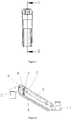
- FIG. 1is a perspective view of the present disclosure
- FIG. 2is an exploded view of the present disclosure
- FIG. 3is a front view of the present disclosure in a first mode
- FIG. 4is a left view the present disclosure in the first mode
- FIG. 5is a sectional view taken along A-A line of FIG. 4 ;
- FIG. 6is a front view of the present disclosure in a second mode
- FIG. 7is a left view of the present disclosure in the second mode
- FIG. 8is a sectional view taken along B-B line of FIG. 7 ;
- FIG. 9is a schematic view of the adjusting means.
- FIG. 1is a perspective view of the present disclosure
- FIG. 2is an exploded view of the present disclosure
- FIG. 3is a front view according to the first embodiment of the present disclosure
- FIG. 4is a left view according to the first embodiment of the present disclosure.
- FIG. 5is a sectional view taken along A-A line of FIG. 4 ;
- FIG. 6is a front view according to the second embodiment of the present disclosure.
- FIG. 7is a left view according to the second embodiment of the present disclosure.
- FIG. 8is a sectional view taken along B-B line of FIG. 7 ;
- FIG. 9is a schematic view of the adjusting means.
- an arm-supporting structureincluding a front arm connector 1 , a rear arm connector 2 , an adjusting means for an upper support 3 and a lower support 4 , and an elastic supporting means 5 .
- the front arm connector 1 , the upper support 3 , the rear arm connector 2 and the lower support 4are hingedly connected sequentially to form a parallelogram structure.
- the upper end and the lower end of the adjusting meansare hingedly connected with the upper support 3 and the lower support 4 , respectively.
- Two ends of the elastic supporting means 5are connected to the adjusting means and the upper support 3 , respectively, and the length of the elastic supporting means 5 is elastically stretchable.
- the front arm connector 1 , the upper support 3 , the rear arm connector 2 and the lower support 4form a parallelogram structure (the parallelogram structure ensures that the front and rear connectors have the same motion angle.
- the rear arm connector 2forms an overall fixed support.
- the front arm connector 1is made to ascend or descend.
- the position of the front arm connectoris supported and oriented by the elastic force from the elastic supporting means 5 .
- the elastic supporting means 5is swinging together with the swinging of the upper support 3 and the lower support 4 swings and changing its length accordingly, and constantly form a stable triangle supporting structure with the adjusting means and the upper support 3 .
- the fulcrum of the elastic supporting means 5is the hinge point between the elastic supporting means and the adjusting means.
- the fulcrumvaries along with the swinging of the upper support and the lower support 4 , and the torque it bears is also varying. It forms a balance with the elastic force that is generated by the elastic stretch from the elastic supporting means 5 when it swings together with the upper support and the lower support 4 .
- the entire supporting structurecan shift the fulcrum automatically to approach a balance. Regardless of the weight of the object to be mounted on the front arm connector, the structure will automatically adjust the fulcrum to reach a balance, and a wide range of bearing capacity is achieved.
- the upper end and the lower end of the adjusting meansare connected, respectively, to the upper support 3 and the lower support 4 , and deliver the force applied thereon to the upper support 3 and the lower support 4 , such that the upper support 3 and the lower support 4 together form a support.
- the adjusting meansdistributes the torque it bears to the upper support 3 and the lower support 4 and the adjusting means itself bears no torsional moment. Therefore, the adjusting means is not prone to damages as it only functions to adjust the length of the elastic supporting means 5 , but not to bear torque.
- the adjusting meansis in parallel with the rear arm connector 2 and the front arm connector 1 .
- the adjusting meansincludes a bracket 6 , a slide block 7 and a height adjusting mechanism.
- the upper and the lower ends of the bracket 6are articulated (i.e., in hinge connection) with the upper support 3 and the lower support 4 , respectively.
- the slide block 7can be positioned movably on the bracket 6 along the extension direction of the bracket 6 .
- the height adjusting mechanismcan drive the movement of the slide block 7 .
- One end of the elastic supporting means 5is articulated with the slide block 7 and slides on the bracket 6 via the slide block 7 .
- the height adjusting mechanismis an adjusting screw 8 which can be rotatably positioned on the bracket 6 in circumferential direction but stopped in axial direction.
- the adjusting screw 8is in threaded connection with the slide block 7 .
- the upper support 3is provided thereon with a hollow portion 17 that is directly facing the head portion of the adjusting screw 8 .
- By rotating the adjusting screw 8the ascending and descending of the slide block 7 is achieved.
- the structureis simple and the adjusting screw 8 is easy and effort-saving to be rotated.
- other height adjusting mechanismsmay be provided, such as a crank-slide block 7 mechanism, a cylinder device or a gear rack mechanism.
- the slide block 7is provided at each of two sides with a first articulating shaft that extends in horizontal direction.
- One end of the elastic supporting means 5is provided with a U-shaped member 9 having two connecting arms.
- the connecting arms of U-shaped connecting member 9are sleeved on two sides of the slide block 7 .
- Each of the connecting arms of the U-shaped member 9is provided thereon with a shaft hole.
- the shaft holeis provided therein with a bearing 10 .
- the first articulating shafts on the two sides of the slide block 7are inserted into the bearings 10 .
- the first articulating shaftis supported by the bearing 10 , which ensures that the first articulating shaft rotates normally, such that the elastic supporting means 5 can swing together with the upper support 3 and the lower support 4 and automatically adjust its position to reach a balance of force.
- the elastic supporting means 5is provided thereon with a stud 11 that extends along an axial direction thereof.
- the U-shaped connecting member 9is provided thereon with a threaded hole.
- the stud 11 on the elastic supporting means 5is in threaded connection with the threaded hole on the U-shaped member 9 .
- the elastic supporting means 5is a gas spring, but can also be a compression spring.
- Two sides of upper end of the adjusting meansare provided, respectively, with a second articulating shaft 12 that extends in horizontal direction.
- the inner side surface of the upper support 3is provided thereon with an opening slot 13 .
- the second articulating shaft 12is rotatably inserted right into the opening slot 13 of the upper support 3 .
- Two sides of lower end of the adjusting meansare each provided with a threaded connecting hole that extends axially in the horizontal direction.
- Two sides at one end of the lower support 4are each provided with a through-hole 14 , and a connecting screw 15 is further provided.
- the connecting screw 15is configured to pass (or penetrate) through the through-hole 14 located on the two sides of the one end of the lower support 4 , and is in threaded connection with the threaded connecting hole provided on the adjusting means.
- the opening slot 13 on the upper support 3is an elongated opening slot structure perpendicular to the inner side surfaces of the upper support 3 .
- An opening portion of the opening slotis provided at each of two inner sides with a chamfer structure.
- the upper support 3 and the lower support 4are in U-shaped structures with openings of the U-shaped structures opposing to each other.
- the sides of two ends of the upper support 3 and the lower support 4are each configured to have an arc-shaped end face.
- the front arm connector 1 and the rear arm connector 2are each inserted into the inner sides of the two ends of the upper support 3 and the lower support 4 .
- the side of the rear arm connector 2is further provided thereon with a curved stepped stopping face 16 that matches the arc-shaped end faces of the upper support 3 and the lower support 4 .
- the arc-shaped end faces of the upper support 3 and the lower support 4are configured to be rotatably stopped by the curved stepped stopping face 16 of the rear arm connector 2 .
- the rear arm connector 2functions to support one end of the upper support 3 and the lower support 4 , to reduce the shear force borne by the hinge bearing 10 , to protect the articulating shaft from damage, and to increase the life span of the whole mechanism.
Landscapes
- Engineering & Computer Science (AREA)
- General Engineering & Computer Science (AREA)
- Mechanical Engineering (AREA)
- Casings For Electric Apparatus (AREA)
Abstract
Description
Claims (2)
Applications Claiming Priority (3)
| Application Number | Priority Date | Filing Date | Title |
|---|---|---|---|
| CN201711286937 | 2017-12-07 | ||
| CN201711286937.XACN107830324B (en) | 2017-12-07 | 2017-12-07 | Arm supporting structure |
| CN201711286937.X | 2017-12-07 |
Publications (2)
| Publication Number | Publication Date |
|---|---|
| US20190178440A1 US20190178440A1 (en) | 2019-06-13 |
| US10760731B2true US10760731B2 (en) | 2020-09-01 |
Family
ID=61642357
Family Applications (1)
| Application Number | Title | Priority Date | Filing Date |
|---|---|---|---|
| US15/941,226Active2038-07-13US10760731B2 (en) | 2017-12-07 | 2018-03-30 | Arm-supporting structure |
Country Status (2)
| Country | Link |
|---|---|
| US (1) | US10760731B2 (en) |
| CN (1) | CN107830324B (en) |
Cited By (5)
| Publication number | Priority date | Publication date | Assignee | Title |
|---|---|---|---|---|
| US11035518B2 (en)* | 2018-08-21 | 2021-06-15 | Modernsolid Industrial Co., Ltd. | Support arm apparatus |
| US11224495B2 (en)* | 2019-06-07 | 2022-01-18 | Welch Allyn, Inc. | Medical device support system |
| US11320090B2 (en)* | 2019-11-21 | 2022-05-03 | Oasys Healthcare Corporation | Arm linkage for device bearing spring arms |
| US20220373126A1 (en)* | 2021-05-24 | 2022-11-24 | Ningbo Tlingt Technology Co., Ltd. | Articulated structure and suspension arm stand having the same |
| US20240090970A1 (en)* | 2020-12-15 | 2024-03-21 | Magventure A/S | A balancing, positioning and fixating assembly |
Families Citing this family (20)
| Publication number | Priority date | Publication date | Assignee | Title |
|---|---|---|---|---|
| US20200025326A1 (en)* | 2018-07-19 | 2020-01-23 | Visioner Inc. | Novel holder |
| CN110770491B (en)* | 2018-08-01 | 2021-08-17 | 深圳市大疆创新科技有限公司 | Shooting equipment and cradle head stability augmentation device thereof |
| TWI663359B (en)* | 2018-08-08 | 2019-06-21 | 青輔實業股份有限公司 | Adjustable cantilever device |
| TWI686687B (en)* | 2018-08-08 | 2020-03-01 | 青輔實業股份有限公司 | Cantilever device |
| CN109550156B (en)* | 2018-12-19 | 2021-01-01 | 广州美锐健康产业股份有限公司 | Suspension arm structure |
| US20210064096A1 (en)* | 2019-08-28 | 2021-03-04 | Intel Corporation | Infinite Holding Pivot Mechanisms for Dual Screen Systems |
| CN110792901A (en)* | 2019-12-06 | 2020-02-14 | 深圳开立生物医疗科技股份有限公司 | Lifting support mechanism and medical equipment |
| JP7721546B2 (en)* | 2020-04-20 | 2025-08-12 | ニンポー トゥオトゥオ リバー デザイン カンパニー | Height-adjustable monitor stand |
| CN111609031B (en)* | 2020-06-24 | 2025-04-08 | 上海安翰医疗技术有限公司 | Mechanical limiting mechanism |
| CN113786248B (en)* | 2021-09-22 | 2022-12-23 | 西安市第一医院 | A slit lamp auxiliary arm bracket |
| CN114135767B (en)* | 2021-12-14 | 2025-05-09 | 宁波沱沱河设计有限公司 | A display stand |
| CN114321635A (en)* | 2021-12-31 | 2022-04-12 | 联想(北京)有限公司 | Supporting device and electronic equipment |
| CN114576513A (en)* | 2022-03-31 | 2022-06-03 | 安徽泓杰人体工学科技有限公司 | Electronic equipment balance force control mechanism |
| CN115325336A (en)* | 2022-07-19 | 2022-11-11 | 中煤科工集团沈阳研究院有限公司 | A gas outburst parameter meter for gas control that is convenient for stable placement |
| USD1078744S1 (en)* | 2022-07-28 | 2025-06-10 | Yiping Huang | Support arm |
| USD1003305S1 (en)* | 2022-12-28 | 2023-10-31 | Ningbo Tuotuo River Design Company | Monitor arm link |
| USD1070827S1 (en)* | 2023-08-10 | 2025-04-15 | Pengyue Liang | Microphone stand |
| JP1787190S (en)* | 2023-11-07 | 2024-12-17 | Monitor Stand | |
| JP1787189S (en)* | 2023-11-07 | 2024-12-17 | Monitor Stand | |
| USD1071910S1 (en)* | 2025-01-17 | 2025-04-22 | Shenzhen Santian Industrial Co., Ltd | Microphone stand |
Citations (25)
| Publication number | Priority date | Publication date | Assignee | Title |
|---|---|---|---|---|
| US1078577A (en)* | 1909-07-01 | 1913-11-11 | Farnham Fox | Telephone-bracket. |
| US4591122A (en)* | 1983-06-06 | 1986-05-27 | Friedhelm Kreuzer | Support structure with a support arm pivotal for height adjustment |
| US4826123A (en)* | 1983-05-16 | 1989-05-02 | Knoll International, Inc. | Adjustable keyboard support |
| US5743503A (en)* | 1996-03-08 | 1998-04-28 | Ergotron, Inc. | Computer suspension system |
| US5826846A (en)* | 1996-06-28 | 1998-10-27 | Hill-Rom, Inc. | Monitor arm with constant counterbalance |
| US5975472A (en)* | 1998-11-19 | 1999-11-02 | Hung; Chin-Jui | Video display support having angle adjustment |
| US5992809A (en)* | 1996-06-07 | 1999-11-30 | Ergotron, Inc. | Mounting system for flat panel display, keyboard, and stand |
| US6012693A (en)* | 1998-02-19 | 2000-01-11 | Ergotron, Inc. | Multi-function display mounting system |
| US6592090B1 (en)* | 2002-08-23 | 2003-07-15 | Chin-Chu Li | Object supporting structure |
| US20050224670A1 (en)* | 2004-04-12 | 2005-10-13 | Andrzej Metelski | Stand, in particular for surgical microscopes, having an energy storage element |
| US20050230585A1 (en)* | 2004-04-19 | 2005-10-20 | Chin-Jui Hung | Support apparatus for suspending a display |
| US20060231710A1 (en)* | 2005-04-19 | 2006-10-19 | Yuan-Hsiang Huang | Flat display holder arm |
| US20070102596A1 (en)* | 2005-11-08 | 2007-05-10 | Roger Sung | Tension adjusting device of support assembly for liquid crystal display |
| US20070108355A1 (en)* | 2004-11-12 | 2007-05-17 | Chin-Chu Li | Supporting shelf |
| US20080029670A1 (en)* | 2006-08-04 | 2008-02-07 | Chin-Jui Hung | Support apparatus for suspending a monitor |
| US7748666B2 (en)* | 2006-09-15 | 2010-07-06 | Innovative Office Products, Inc. | Extension arm with moving clevis |
| US20110147546A1 (en)* | 2009-12-23 | 2011-06-23 | Humanscale Corporation | Adjustable Display Arm |
| US20110260017A1 (en)* | 2010-04-23 | 2011-10-27 | Humanscale Corporation | Adjustable Support Arm |
| US20110315843A1 (en)* | 2010-06-24 | 2011-12-29 | Modernsolid Industrial Co., Ltd. | Supporting arm assembly for a display |
| US20130009034A1 (en)* | 2011-07-05 | 2013-01-10 | Mediamounts, Ltd. | Dual bar linkage monitor support with adustment feature |
| US20130161465A1 (en)* | 2011-12-22 | 2013-06-27 | Ming Hua Huang | Support Arm Structure |
| US8777172B2 (en)* | 2011-06-07 | 2014-07-15 | Knoll, Inc. | Support apparatus for display devices and other objects |
| US9243743B2 (en)* | 2013-03-01 | 2016-01-26 | Icwusa.Com, Inc. | Support arm |
| US20170082819A1 (en)* | 2015-09-22 | 2017-03-23 | Novartis Ag | Brake system |
| US9657889B1 (en)* | 2013-03-15 | 2017-05-23 | Humanscale Corporation | Adjustable support arm |
Family Cites Families (13)
| Publication number | Priority date | Publication date | Assignee | Title |
|---|---|---|---|---|
| CN100342298C (en)* | 2005-01-25 | 2007-10-10 | 名达亚洲有限公司 | Three-dimensionally adjustable computer flat display support device |
| CN201636510U (en)* | 2010-03-26 | 2010-11-17 | 东莞照彰五金电器制品有限公司 | LCD support |
| CN201723633U (en)* | 2010-07-01 | 2011-01-26 | 深圳市蓝韵实业有限公司 | Adjustable connecting rod support |
| CN202181177U (en)* | 2011-07-15 | 2012-04-04 | 宁波乐歌视讯科技股份有限公司 | Self-balancing linking arm |
| CN202647129U (en)* | 2012-06-13 | 2013-01-02 | 昆山呈杰电脑配件有限公司 | Display lifting structure adopting gas spring |
| CN202834623U (en)* | 2012-09-11 | 2013-03-27 | 北京东方惠尔图像技术有限公司 | Displayer support |
| CN105299413B (en)* | 2014-06-12 | 2018-01-09 | 昆山泓杰电子股份有限公司 | Height Adjustable cantilever type television machine support |
| CN204785361U (en)* | 2015-07-07 | 2015-11-18 | 昆山泓杰电子有限公司 | Adjustable constant force formula supporting mechanism |
| CN106195567A (en)* | 2016-08-25 | 2016-12-07 | 昆山泓杰电子股份有限公司 | Stand and sit dual-purpose work supporting stand |
| CN106195559B (en)* | 2016-08-25 | 2019-11-01 | 昆山泓杰电子股份有限公司 | The adjusting supporting mechanism of display bracket |
| CN106195587A (en)* | 2016-08-26 | 2016-12-07 | 昆山泓杰电子股份有限公司 | Table upper bracket |
| CN205956672U (en)* | 2016-08-26 | 2017-02-15 | 昆山奇朗数码科技有限公司 | Power value adjustable structure of display support |
| CN207687580U (en)* | 2017-12-07 | 2018-08-03 | 昆山泓杰电子股份有限公司 | Arm support structure |
- 2017
- 2017-12-07CNCN201711286937.XApatent/CN107830324B/enactiveActive
- 2018
- 2018-03-30USUS15/941,226patent/US10760731B2/enactiveActive
Patent Citations (28)
| Publication number | Priority date | Publication date | Assignee | Title |
|---|---|---|---|---|
| US1078577A (en)* | 1909-07-01 | 1913-11-11 | Farnham Fox | Telephone-bracket. |
| US4826123A (en)* | 1983-05-16 | 1989-05-02 | Knoll International, Inc. | Adjustable keyboard support |
| US4591122A (en)* | 1983-06-06 | 1986-05-27 | Friedhelm Kreuzer | Support structure with a support arm pivotal for height adjustment |
| US5743503A (en)* | 1996-03-08 | 1998-04-28 | Ergotron, Inc. | Computer suspension system |
| US5992809A (en)* | 1996-06-07 | 1999-11-30 | Ergotron, Inc. | Mounting system for flat panel display, keyboard, and stand |
| US5826846A (en)* | 1996-06-28 | 1998-10-27 | Hill-Rom, Inc. | Monitor arm with constant counterbalance |
| US6012693A (en)* | 1998-02-19 | 2000-01-11 | Ergotron, Inc. | Multi-function display mounting system |
| US5975472A (en)* | 1998-11-19 | 1999-11-02 | Hung; Chin-Jui | Video display support having angle adjustment |
| US6592090B1 (en)* | 2002-08-23 | 2003-07-15 | Chin-Chu Li | Object supporting structure |
| US20050224670A1 (en)* | 2004-04-12 | 2005-10-13 | Andrzej Metelski | Stand, in particular for surgical microscopes, having an energy storage element |
| US20050230585A1 (en)* | 2004-04-19 | 2005-10-20 | Chin-Jui Hung | Support apparatus for suspending a display |
| US20070108355A1 (en)* | 2004-11-12 | 2007-05-17 | Chin-Chu Li | Supporting shelf |
| US20060231710A1 (en)* | 2005-04-19 | 2006-10-19 | Yuan-Hsiang Huang | Flat display holder arm |
| US20070102596A1 (en)* | 2005-11-08 | 2007-05-10 | Roger Sung | Tension adjusting device of support assembly for liquid crystal display |
| US20080029670A1 (en)* | 2006-08-04 | 2008-02-07 | Chin-Jui Hung | Support apparatus for suspending a monitor |
| US7338022B2 (en)* | 2006-08-04 | 2008-03-04 | Chin-Jui Hung | Support apparatus for suspending a monitor |
| US7748666B2 (en)* | 2006-09-15 | 2010-07-06 | Innovative Office Products, Inc. | Extension arm with moving clevis |
| US20110147546A1 (en)* | 2009-12-23 | 2011-06-23 | Humanscale Corporation | Adjustable Display Arm |
| US20110260017A1 (en)* | 2010-04-23 | 2011-10-27 | Humanscale Corporation | Adjustable Support Arm |
| US8366060B2 (en)* | 2010-06-24 | 2013-02-05 | Modernsolid Industrial Co., Ltd. | Supporting arm assembly for a display |
| US20110315843A1 (en)* | 2010-06-24 | 2011-12-29 | Modernsolid Industrial Co., Ltd. | Supporting arm assembly for a display |
| US8777172B2 (en)* | 2011-06-07 | 2014-07-15 | Knoll, Inc. | Support apparatus for display devices and other objects |
| US20130009034A1 (en)* | 2011-07-05 | 2013-01-10 | Mediamounts, Ltd. | Dual bar linkage monitor support with adustment feature |
| US8960632B2 (en)* | 2011-07-05 | 2015-02-24 | Mediamounts, Ltd. | Dual bar linkage monitor support with adustment feature |
| US20130161465A1 (en)* | 2011-12-22 | 2013-06-27 | Ming Hua Huang | Support Arm Structure |
| US9243743B2 (en)* | 2013-03-01 | 2016-01-26 | Icwusa.Com, Inc. | Support arm |
| US9657889B1 (en)* | 2013-03-15 | 2017-05-23 | Humanscale Corporation | Adjustable support arm |
| US20170082819A1 (en)* | 2015-09-22 | 2017-03-23 | Novartis Ag | Brake system |
Cited By (7)
| Publication number | Priority date | Publication date | Assignee | Title |
|---|---|---|---|---|
| US11035518B2 (en)* | 2018-08-21 | 2021-06-15 | Modernsolid Industrial Co., Ltd. | Support arm apparatus |
| US11224495B2 (en)* | 2019-06-07 | 2022-01-18 | Welch Allyn, Inc. | Medical device support system |
| US11684449B2 (en) | 2019-06-07 | 2023-06-27 | Welch Allyn, Inc. | Medical device support system |
| US11320090B2 (en)* | 2019-11-21 | 2022-05-03 | Oasys Healthcare Corporation | Arm linkage for device bearing spring arms |
| US20240090970A1 (en)* | 2020-12-15 | 2024-03-21 | Magventure A/S | A balancing, positioning and fixating assembly |
| US12426986B2 (en)* | 2020-12-15 | 2025-09-30 | Magventure A/S | Balancing, positioning and fixating assembly |
| US20220373126A1 (en)* | 2021-05-24 | 2022-11-24 | Ningbo Tlingt Technology Co., Ltd. | Articulated structure and suspension arm stand having the same |
Also Published As
| Publication number | Publication date |
|---|---|
| CN107830324B (en) | 2024-06-07 |
| US20190178440A1 (en) | 2019-06-13 |
| CN107830324A (en) | 2018-03-23 |
Similar Documents
| Publication | Publication Date | Title |
|---|---|---|
| US10760731B2 (en) | Arm-supporting structure | |
| CA2512839C (en) | Articulated mount | |
| US8891249B2 (en) | Display mount with adjustable position tilt axis | |
| US9027894B2 (en) | Support apparatus for display devices and other objects | |
| US7726616B2 (en) | Support stand for flat-panel display monitor | |
| US10295114B2 (en) | Supporting module | |
| WO2021213342A1 (en) | Display support having freely adjustable height | |
| WO2006132781A2 (en) | Self-balancing adjustable mounting system with friction adjustment | |
| WO2011156569A1 (en) | Articulating monitor arm with chain and spring | |
| US20220373126A1 (en) | Articulated structure and suspension arm stand having the same | |
| US9456511B2 (en) | Support assembly for a device | |
| CN111609277A (en) | Display support with freely adjustable height | |
| CN219635116U (en) | Self-driving car and its camera mounting bracket | |
| CN114658997B (en) | Display support | |
| CN113107118B (en) | Stainless steel connection claw for curtain wall installation fitting | |
| CA2682418A1 (en) | Dental apparatus having an adjustable articulated arm | |
| CN223204077U (en) | Angle adjusting mechanism of display support and corresponding display support | |
| CN217153681U (en) | Display support | |
| CN216118599U (en) | Angle adjusting mechanism and electronic equipment | |
| KR200448395Y1 (en) | Tension spring adjusting device mounted on the arm stand for display device | |
| CN203852427U (en) | Indoor tower crane | |
| CN222558377U (en) | A bearing structure and door and window device | |
| CN216414507U (en) | Microphone bracket | |
| CN215111877U (en) | Projection equipment hanger | |
| TWM529101U (en) | Simple liftingbracket |
Legal Events
| Date | Code | Title | Description |
|---|---|---|---|
| AS | Assignment | Owner name:KUNSHAN HONGJIE ELECTRONICS CO., LTD., CHINA Free format text:ASSIGNMENT OF ASSIGNORS INTEREST;ASSIGNOR:CHANG, XIAOJIE;REEL/FRAME:045395/0505 Effective date:20180320 | |
| FEPP | Fee payment procedure | Free format text:ENTITY STATUS SET TO UNDISCOUNTED (ORIGINAL EVENT CODE: BIG.); ENTITY STATUS OF PATENT OWNER: SMALL ENTITY | |
| FEPP | Fee payment procedure | Free format text:ENTITY STATUS SET TO SMALL (ORIGINAL EVENT CODE: SMAL); ENTITY STATUS OF PATENT OWNER: SMALL ENTITY | |
| STPP | Information on status: patent application and granting procedure in general | Free format text:DOCKETED NEW CASE - READY FOR EXAMINATION | |
| STPP | Information on status: patent application and granting procedure in general | Free format text:NON FINAL ACTION MAILED | |
| STPP | Information on status: patent application and granting procedure in general | Free format text:RESPONSE TO NON-FINAL OFFICE ACTION ENTERED AND FORWARDED TO EXAMINER | |
| STPP | Information on status: patent application and granting procedure in general | Free format text:PUBLICATIONS -- ISSUE FEE PAYMENT VERIFIED | |
| STCF | Information on status: patent grant | Free format text:PATENTED CASE | |
| MAFP | Maintenance fee payment | Free format text:PAYMENT OF MAINTENANCE FEE, 4TH YR, SMALL ENTITY (ORIGINAL EVENT CODE: M2551); ENTITY STATUS OF PATENT OWNER: SMALL ENTITY Year of fee payment:4 |