US10760384B2 - Method of creating and finishing perforations in a hydrocarbon well - Google Patents
Method of creating and finishing perforations in a hydrocarbon wellDownload PDFInfo
- Publication number
- US10760384B2 US10760384B2US16/036,920US201816036920AUS10760384B2US 10760384 B2US10760384 B2US 10760384B2US 201816036920 AUS201816036920 AUS 201816036920AUS 10760384 B2US10760384 B2US 10760384B2
- Authority
- US
- United States
- Prior art keywords
- propellant
- pieces
- piece
- combustion
- container
- Prior art date
- Legal status (The legal status is an assumption and is not a legal conclusion. Google has not performed a legal analysis and makes no representation as to the accuracy of the status listed.)
- Active, expires
Links
- 238000000034methodMethods0.000titleclaimsabstractdescription22
- 229930195733hydrocarbonNatural products0.000titleclaimsabstractdescription12
- 150000002430hydrocarbonsChemical class0.000titleclaimsabstractdescription12
- 239000004215Carbon black (E152)Substances0.000titleclaimsabstractdescription10
- 230000007423decreaseEffects0.000claimsabstractdescription13
- 239000003380propellantSubstances0.000claimsdescription70
- 238000002485combustion reactionMethods0.000claimsdescription30
- 239000002923metal particleSubstances0.000claimsdescription5
- 239000000463materialSubstances0.000abstractdescription3
- 239000007789gasSubstances0.000description23
- 239000011435rockSubstances0.000description10
- 229910000831SteelInorganic materials0.000description8
- 239000010959steelSubstances0.000description8
- RYGMFSIKBFXOCR-UHFFFAOYSA-NCopperChemical compound[Cu]RYGMFSIKBFXOCR-UHFFFAOYSA-N0.000description4
- 229910052802copperInorganic materials0.000description4
- 239000010949copperSubstances0.000description4
- 239000000020NitrocelluloseSubstances0.000description3
- 229920001220nitrocellulosPolymers0.000description3
- 239000002245particleSubstances0.000description3
- SNIOPGDIGTZGOP-UHFFFAOYSA-NNitroglycerinChemical compound[O-][N+](=O)OCC(O[N+]([O-])=O)CO[N+]([O-])=OSNIOPGDIGTZGOP-UHFFFAOYSA-N0.000description2
- 239000000006NitroglycerinSubstances0.000description2
- 238000007792additionMethods0.000description2
- 239000002360explosiveSubstances0.000description2
- 229960003711glyceryl trinitrateDrugs0.000description2
- 239000007788liquidSubstances0.000description2
- 238000012986modificationMethods0.000description2
- 230000004048modificationEffects0.000description2
- QVGXLLKOCUKJST-UHFFFAOYSA-Natomic oxygenChemical compound[O]QVGXLLKOCUKJST-UHFFFAOYSA-N0.000description1
- 239000004568cementSubstances0.000description1
- 230000003247decreasing effectEffects0.000description1
- 238000005474detonationMethods0.000description1
- 239000000446fuelSubstances0.000description1
- 239000002184metalSubstances0.000description1
- 229910052751metalInorganic materials0.000description1
- 239000007800oxidant agentSubstances0.000description1
- 239000001301oxygenSubstances0.000description1
- 229910052760oxygenInorganic materials0.000description1
Images


Classifications
- E—FIXED CONSTRUCTIONS
- E21—EARTH OR ROCK DRILLING; MINING
- E21B—EARTH OR ROCK DRILLING; OBTAINING OIL, GAS, WATER, SOLUBLE OR MELTABLE MATERIALS OR A SLURRY OF MINERALS FROM WELLS
- E21B43/00—Methods or apparatus for obtaining oil, gas, water, soluble or meltable materials or a slurry of minerals from wells
- E21B43/11—Perforators; Permeators
- E21B43/116—Gun or shaped-charge perforators
- E21B43/117—Shaped-charge perforators
- E—FIXED CONSTRUCTIONS
- E21—EARTH OR ROCK DRILLING; MINING
- E21B—EARTH OR ROCK DRILLING; OBTAINING OIL, GAS, WATER, SOLUBLE OR MELTABLE MATERIALS OR A SLURRY OF MINERALS FROM WELLS
- E21B43/00—Methods or apparatus for obtaining oil, gas, water, soluble or meltable materials or a slurry of minerals from wells
- E21B43/11—Perforators; Permeators
- E21B43/116—Gun or shaped-charge perforators
- E21B43/118—Gun or shaped-charge perforators characterised by lowering in vertical position and subsequent tilting to operating position
- F—MECHANICAL ENGINEERING; LIGHTING; HEATING; WEAPONS; BLASTING
- F42—AMMUNITION; BLASTING
- F42B—EXPLOSIVE CHARGES, e.g. FOR BLASTING, FIREWORKS, AMMUNITION
- F42B3/00—Blasting cartridges, i.e. case and explosive
- F42B3/22—Elements for controlling or guiding the detonation wave, e.g. tubes
- F—MECHANICAL ENGINEERING; LIGHTING; HEATING; WEAPONS; BLASTING
- F42—AMMUNITION; BLASTING
- F42D—BLASTING
- F42D1/00—Blasting methods or apparatus, e.g. loading or tamping
- F42D1/04—Arrangements for ignition
- F42D1/043—Connectors for detonating cords and ignition tubes, e.g. Nonel tubes
- F—MECHANICAL ENGINEERING; LIGHTING; HEATING; WEAPONS; BLASTING
- F42—AMMUNITION; BLASTING
- F42D—BLASTING
- F42D1/00—Blasting methods or apparatus, e.g. loading or tamping
- F42D1/04—Arrangements for ignition
- F42D1/045—Arrangements for electric ignition
- Y—GENERAL TAGGING OF NEW TECHNOLOGICAL DEVELOPMENTS; GENERAL TAGGING OF CROSS-SECTIONAL TECHNOLOGIES SPANNING OVER SEVERAL SECTIONS OF THE IPC; TECHNICAL SUBJECTS COVERED BY FORMER USPC CROSS-REFERENCE ART COLLECTIONS [XRACs] AND DIGESTS
- Y10—TECHNICAL SUBJECTS COVERED BY FORMER USPC
- Y10T—TECHNICAL SUBJECTS COVERED BY FORMER US CLASSIFICATION
- Y10T29/00—Metal working
- Y10T29/49—Method of mechanical manufacture
- Y10T29/49826—Assembling or joining
Definitions
- Embodiments hereinpertain to creating and finishing perforations in a hydrocarbon well.
- a hydrocarbon well(oil or gas) is typically finished using a device known as a perforating gun.
- This deviceincludes a steel tube containing a set of devices, typically referred to as “shaped charges” each of which includes a charge of high explosive and a small amount of copper.
- the tubeis lowered into the well, and the high explosive charges are detonated, fragmenting the copper and accelerating the resultant copper particles to a speed on the order of 30 mach, so that it blasts through the wall of the steel tube, through any steel casing forming the wall of the well, and perforates the surrounding rock, thereby permitting oil or gas or both to flow into the well.
- the resultant perforationhas some characteristics that inhibit the flow of liquid or gas into the perforation from the surrounding rock.
- the copper particlespush into the rock it pushes the rock immediately in its path rearward and to the side, and also heats this rock, resulting in perforation surfaces that are less permeable to the flow of liquids and gasses than would otherwise be the case.
- Embodiments hereinpertain to a method of creating and finishing perforations in a hydrocarbon well having a well wall that may include one or more of: shooting a high velocity jet of metal particles into the well wall, thereby creating a perforation in the well wall; pushing a gas blast into the perforation, for a blast time duration, the gas blast creating an increasing pressure at the perforation, until a maximum is reached, the pressure of the gas then undergoing a period of rapid decline to a level of less than 50% of the maximum pressure.
- the period of rapid declinetakes less than one-sixth of the blast time duration.
- the time pattern of speed and pressure of the gas blastmay result in a higher maximum pressure at the perforation than would have happened had the maximum pressure been reached midway through the gas blast, thereby resulting in localized fracturing, emanating from the perforation. This may permit a greater flow of hydrocarbons into the perforation and from the perforation into the well.
- the period of rapid declinemay take less than one-tenth of the blast time duration.
- the gas blastmay flow at an increasing speed, as the pressure increases.
- inventions hereinpertain to a method of creating and finishing perforations in a hydrocarbon well having a well wall that may include one or more of: operating a perforation assembly to cause a high velocity jet of a material to shoot into the well wall, thereby creating a perforation in the well wall.
- the perforation assemblymay include: a tube having a tube wall; a plurality of shaped charges disposed within the tube and adapted to shoot the high velocity jet through the tube wall and into the well wall; a propellant also disposed within the tube, the propellant having a surface area; and a detonating cord operable to ignite the shaped charges and the propellant.
- the propellantmay be configured to undergo a combustion until it is substantially consumed by the combustion.
- the propellantmay initially combust slowly enough that the combustion of the propellant does not interfere with functioning of an at least one of any of the plurality of shaped charges.
- the methodmay further include introducing a gas blast into the perforation for a blast time duration, the gas blast eventually reaching a maximum pressure.
- the methodmay include allowing a pressure of the gas blast to undergo a period of rapid decline to a level of less than 50% of the maximum pressure.
- the period of rapid declinemay take less than one-sixth of the blast time duration.
- Still other embodiments hereinpertain to a method of perforating a well wall that may include one or more of: providing a perforation creating-and-finishing assembly for use in a well having a well wall.
- the assemblymay include: a tube having a tube wall; a plurality of shaped charges positioned within the tube; a propellant also positioned within the tube, the propellant having a surface area and being configured so as to combust at an increasing rate until substantially consumed; and a detonator disposed within the tube.
- the methodmay include lowering the assembly into the well to a predetermined position.
- the methodmay include operating the assembly to ignite the detonator, thereby igniting the plurality of shaped charges and the propellant.
- the plurality of shaped chargesmay be configured to provide or facilitate the shooting of a high velocity jet of metal particles through the tube wall and into the well wall, thereby creating a perforation.
- Yet still other embodiments of the disclosurepertain to a method of creating and finishing perforations in a hydrocarbon well having a well wall that may include one or more of: causing a high velocity jet of a material to shoot into the well wall, thereby creating a perforation in the well wall; introducing a gas blast into the perforation, for a blast time duration, the gas blast creating an increasing pressure at the perforation until a maximum pressure is reached; and allowing the pressure of the gas blast to undergo a period of rapid decline to a level of less than 50% of the maximum pressure.
- the period of rapid declinemay take less than one-sixth of the blast time duration.
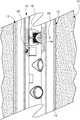
- FIG. 1is a sectional view 5 of a portion of a hydrocarbon well having a perforation creating and finishing device, shown in a side view for ease of description.
- FIG. 2shows the environment and device of FIG. 1 , during detonation of the device.
- FIG. 3shows the environment and device of FIG. 1 , at a further stage of deployment, after a perforation in the well wall has been created.
- FIG. 4is an expanded sectional detail view of the well wall perforation of FIG. 3 , taken along line 4 - 4 of FIG. 3 .
- FIG. 5shows the environment and device of FIG. 1 , at a final stage of deployment, showing the finished perforation.
- FIG. 6is an expanded sectional detail view of the finished well wall perforation of FIG. 5 , taken along line 6 - 6 of FIG. 5 .
- FIG. 7is an isometric view of a cylindrical carton filled with pieces of propellant.
- FIG. 8is a graph of combustion rate over time of the propellant in the device of FIGS. 1-3 and 5 .
- a perforating gun 15is lowered into proximity of a portion of wall 10 , to be treated.
- Perforating gun 15includes a charge tube 16 , which supports a number of shaped charges 18 , containers 20 of propellant 38 ( FIG. 7 ) and a detonating cord 22 , all encased in a fluid-impermeable sealed steel carrier 24 .
- the detonating cord 22is ignited, causing the shaped charges 18 to expel particles of metal 26 ( FIG. 2 —shown as an ellipse for ease of presentation) at a high velocity, within ten microseconds. Travelling at approximately 30 mach, the metal particles 26 penetrate through steel carrier 24 , creating a carrier perforation 27 ( FIG. 3 ) and into the wall 10 , creating a perforation 28 ( FIG. 3 ) through the steel casing 12 , and a further perforation 29 ( FIG. 3 ) in the rock 14 , thereby facilitating the flow of hydrocarbons into the well.
- the movement of the metal particles 26 into the rockcreates a perforation 29 , having walls 30 , which have been seared and made more dense by rock 14 that has been pushed to the side or pushed toward the back of the perforation 29 . Consequently, the perforation does not facilitate the flow of oil as much as might be possible.
- the containers 20 of propellant 38combust over a period between 10 and 100 milliseconds, far more slowly than the action of the shaped charges 18 .
- the rate of combustion 56 of the propellant 38increases with greater pressure, causing the combustion rate to increase at a greater than linear rate 48 as some propellant 38 combusts and the gas thereby released creates a higher pressure; however, at least one additional piece 39 of propellant 38 may not combust at an increasing rate after being ignited.
- the combustionhas spread over the surface areas of the pieces 39 of propellant 38 ( FIG. 7 ), including the interior surface areas, created by a set of seven through-holes 40 in each piece 39 of propellant 38 .
- the pieces 39 of propellant 38are packed together in groups, with each group including seven pieces 39 of propellant 38 , and being interposed between two shaped charges.
- the combustion rate 48 of propellant 38reaches a maximum 50 ( FIG. 8 ), directly before the fuel is exhausted, resulting in a high maximum combustion rate 50 , followed by a rapid plunge 58 to zero 60 .
- the rapid decline 58takes less than one-sixth of the blast time duration. In another preferred embodiment, the rapid decline 58 takes less than one-tenth of the blast time duration. Not only does the combustion rate increase due to through-holes 40 , but also because propellant 38 combusts more rapidly under higher pressure.
- the combustion cessation periodtakes less than one-tenth of the total time period of combustion 56 .
- the combustion cessation periodis less than one-thirtieth of the period of combustion 56 (for the same piece 39 of propellant 38 ).
- the hot gas 70that is the product of the propellant combustion is pushed rapidly and forcefully out of the tubing carrier perforations 27 with increasing speed that is proportional to the increasing pressure caused by the gas blast, and into well wall perforations 28 and 29 , which are still fairly well aligned with carrier perforation 27 , as the relatively massive perforating gun 16 accelerates and moves relatively slowly.
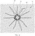
- the pressure created by gas 70increases until a maximum is reached before declining rapidly. Both the speed and the pressure of the gas 70 act to break apart the rock 14 , and create a star pattern of fissures 72 emanating radially from perforation 28 , thereby facilitating the flow of oil and gas into the well.
- the through-holes 40 of propellant 38result in a higher maximum combustion rate and a corresponding higher pressure at perforation 29 , than would be otherwise the case. Surprisingly, because of the through-holes 40 , the maximum pressure applied to the perforations 29 is high enough to be effective, even though large portions of steel carrier 24 are taken up by shaped charges 18 , and thereby not available for stowage of propellant 38 .
- the propellant 38includes its own oxidizer, and so does not need any external source of oxygen to combust. Further, propellant 38 may be either single-based (nitrocellulose), double-based (nitrocellulose and nitroglycerin), or triple-based (nitrocellulose, nitroglycerin, and nitroguanadine). These propellants may be available from BAE Systems, in Radford, Va.
Landscapes
- Life Sciences & Earth Sciences (AREA)
- Engineering & Computer Science (AREA)
- Geology (AREA)
- Mining & Mineral Resources (AREA)
- Physics & Mathematics (AREA)
- Environmental & Geological Engineering (AREA)
- Fluid Mechanics (AREA)
- General Life Sciences & Earth Sciences (AREA)
- Geochemistry & Mineralogy (AREA)
- Portable Nailing Machines And Staplers (AREA)
- Drilling And Exploitation, And Mining Machines And Methods (AREA)
Abstract
Description
Claims (20)
Priority Applications (3)
| Application Number | Priority Date | Filing Date | Title |
|---|---|---|---|
| US16/036,920US10760384B2 (en) | 2014-12-30 | 2018-07-16 | Method of creating and finishing perforations in a hydrocarbon well |
| US16/292,620US11073005B2 (en) | 2014-12-30 | 2019-03-05 | Propellant container for a perforating gun |
| US17/384,947US20210355796A1 (en) | 2014-12-30 | 2021-07-26 | Propellant container for a perforating gun |
Applications Claiming Priority (2)
| Application Number | Priority Date | Filing Date | Title |
|---|---|---|---|
| US14/585,956US10024145B1 (en) | 2014-12-30 | 2014-12-30 | Method of creating and finishing perforations in a hydrocarbon well |
| US16/036,920US10760384B2 (en) | 2014-12-30 | 2018-07-16 | Method of creating and finishing perforations in a hydrocarbon well |
Related Parent Applications (1)
| Application Number | Title | Priority Date | Filing Date |
|---|---|---|---|
| US14/585,956ContinuationUS10024145B1 (en) | 2014-12-30 | 2014-12-30 | Method of creating and finishing perforations in a hydrocarbon well |
Related Child Applications (1)
| Application Number | Title | Priority Date | Filing Date |
|---|---|---|---|
| US16/292,620Continuation-In-PartUS11073005B2 (en) | 2014-12-30 | 2019-03-05 | Propellant container for a perforating gun |
Publications (2)
| Publication Number | Publication Date |
|---|---|
| US20180320491A1 US20180320491A1 (en) | 2018-11-08 |
| US10760384B2true US10760384B2 (en) | 2020-09-01 |
Family
ID=62837121
Family Applications (2)
| Application Number | Title | Priority Date | Filing Date |
|---|---|---|---|
| US14/585,956Active2036-08-31US10024145B1 (en) | 2014-12-30 | 2014-12-30 | Method of creating and finishing perforations in a hydrocarbon well |
| US16/036,920Active2035-03-06US10760384B2 (en) | 2014-12-30 | 2018-07-16 | Method of creating and finishing perforations in a hydrocarbon well |
Family Applications Before (1)
| Application Number | Title | Priority Date | Filing Date |
|---|---|---|---|
| US14/585,956Active2036-08-31US10024145B1 (en) | 2014-12-30 | 2014-12-30 | Method of creating and finishing perforations in a hydrocarbon well |
Country Status (1)
| Country | Link |
|---|---|
| US (2) | US10024145B1 (en) |
Cited By (1)
| Publication number | Priority date | Publication date | Assignee | Title |
|---|---|---|---|---|
| US11767739B2 (en)* | 2020-04-30 | 2023-09-26 | Expro Americas, Llc | Perforating gun for oil and gas wells, and system and method for using the same |
Families Citing this family (3)
| Publication number | Priority date | Publication date | Assignee | Title |
|---|---|---|---|---|
| US10024145B1 (en)* | 2014-12-30 | 2018-07-17 | The Gasgun, Inc. | Method of creating and finishing perforations in a hydrocarbon well |
| US10907460B2 (en)* | 2018-02-12 | 2021-02-02 | The Johns Hopkins University | Energetic charge for propellant fracturing |
| US11002119B2 (en) | 2019-06-13 | 2021-05-11 | Halliburton Energy Services, Inc. | Energetic perforator fill and delay method |
Citations (30)
| Publication number | Priority date | Publication date | Assignee | Title |
|---|---|---|---|---|
| US3422760A (en) | 1966-10-05 | 1969-01-21 | Petroleum Tool Research Inc | Gas-generating device for stimulating the flow of well fluids |
| US3630284A (en)* | 1970-04-02 | 1971-12-28 | Amoco Prod Co | Method for treatment of fluid-bearing formations |
| US4039030A (en) | 1976-06-28 | 1977-08-02 | Physics International Company | Oil and gas well stimulation |
| US4081031A (en) | 1976-09-13 | 1978-03-28 | Kine-Tech Corporation | Oil well stimulation method |
| US4386569A (en) | 1979-05-30 | 1983-06-07 | The United States Of America As Represented By The Secretary Of The Army | Solid propellant grain for improved ballistic performance guns |
| US4391337A (en) | 1981-03-27 | 1983-07-05 | Ford Franklin C | High-velocity jet and propellant fracture device for gas and oil well production |
| US4491185A (en) | 1983-07-25 | 1985-01-01 | Mcclure Gerald B | Method and apparatus for perforating subsurface earth formations |
| US4548252A (en) | 1984-04-04 | 1985-10-22 | Mobil Oil Corporation | Controlled pulse fracturing |
| US4633951A (en) | 1984-12-27 | 1987-01-06 | Mt. Moriah Trust | Well treating method for stimulating recovery of fluids |
| US4673039A (en) | 1986-01-24 | 1987-06-16 | Mohaupt Henry H | Well completion technique |
| US4798244A (en) | 1987-07-16 | 1989-01-17 | Trost Stephen A | Tool and process for stimulating a subterranean formation |
| US5212342A (en)* | 1991-02-11 | 1993-05-18 | Giat Industries | Container for receiving propellant charges |
| US5295545A (en) | 1992-04-14 | 1994-03-22 | University Of Colorado Foundation Inc. | Method of fracturing wells using propellants |
| US5690171A (en) | 1994-09-20 | 1997-11-25 | Winch; Peter Clive | Wellbore stimulation and completion |
| US6082450A (en) | 1996-09-09 | 2000-07-04 | Marathon Oil Company | Apparatus and method for stimulating a subterranean formation |
| US6354219B1 (en) | 1998-05-01 | 2002-03-12 | Owen Oil Tools, Inc. | Shaped-charge liner |
| US20030155125A1 (en) | 2002-01-22 | 2003-08-21 | Tiernan John P. | System for fracturing wells using supplemental longer-burning propellants |
| US20030155112A1 (en) | 2002-01-11 | 2003-08-21 | Tiernan John P. | Modular propellant assembly for fracturing wells |
| US20050109509A1 (en) | 2003-11-08 | 2005-05-26 | Snider Philip M. | Propellant ignition assembly and process |
| US6991044B2 (en) | 2001-02-06 | 2006-01-31 | Xi'an Tongyuan Petrotech Co., Ltd. | High-energy combined well perforating device |
| US20060185898A1 (en) | 2005-02-23 | 2006-08-24 | Dale Seekford | Method and apparatus for stimulating wells with propellants |
| US20070084604A1 (en) | 2005-10-18 | 2007-04-19 | Owen Oil Tools Lp | System and method for performing multiple downhole operations |
| US7228907B2 (en) | 2005-07-22 | 2007-06-12 | The Gas Gun, Llc | High energy gas fracturing charge device and method of use |
| US7393423B2 (en)* | 2001-08-08 | 2008-07-01 | Geodynamics, Inc. | Use of aluminum in perforating and stimulating a subterranean formation and other engineering applications |
| US7431075B2 (en) | 2004-10-05 | 2008-10-07 | Schlumberger Technology Corporation | Propellant fracturing of wells |
| US7913761B2 (en) | 2005-10-18 | 2011-03-29 | Owen Oil Tools Lp | System and method for enhanced wellbore perforations |
| US8336437B2 (en) | 2009-07-01 | 2012-12-25 | Halliburton Energy Services, Inc. | Perforating gun assembly and method for controlling wellbore pressure regimes during perforating |
| US8342094B2 (en) | 2009-10-22 | 2013-01-01 | Schlumberger Technology Corporation | Dissolvable material application in perforating |
| US8381652B2 (en) | 2010-03-09 | 2013-02-26 | Halliburton Energy Services, Inc. | Shaped charge liner comprised of reactive materials |
| US10024145B1 (en)* | 2014-12-30 | 2018-07-17 | The Gasgun, Inc. | Method of creating and finishing perforations in a hydrocarbon well |
- 2014
- 2014-12-30USUS14/585,956patent/US10024145B1/enactiveActive
- 2018
- 2018-07-16USUS16/036,920patent/US10760384B2/enactiveActive
Patent Citations (32)
| Publication number | Priority date | Publication date | Assignee | Title |
|---|---|---|---|---|
| US3422760A (en) | 1966-10-05 | 1969-01-21 | Petroleum Tool Research Inc | Gas-generating device for stimulating the flow of well fluids |
| US3630284A (en)* | 1970-04-02 | 1971-12-28 | Amoco Prod Co | Method for treatment of fluid-bearing formations |
| US4039030A (en) | 1976-06-28 | 1977-08-02 | Physics International Company | Oil and gas well stimulation |
| US4081031A (en) | 1976-09-13 | 1978-03-28 | Kine-Tech Corporation | Oil well stimulation method |
| US4386569A (en) | 1979-05-30 | 1983-06-07 | The United States Of America As Represented By The Secretary Of The Army | Solid propellant grain for improved ballistic performance guns |
| US4391337A (en) | 1981-03-27 | 1983-07-05 | Ford Franklin C | High-velocity jet and propellant fracture device for gas and oil well production |
| US4491185A (en) | 1983-07-25 | 1985-01-01 | Mcclure Gerald B | Method and apparatus for perforating subsurface earth formations |
| US4548252A (en) | 1984-04-04 | 1985-10-22 | Mobil Oil Corporation | Controlled pulse fracturing |
| US4633951A (en) | 1984-12-27 | 1987-01-06 | Mt. Moriah Trust | Well treating method for stimulating recovery of fluids |
| US4673039A (en) | 1986-01-24 | 1987-06-16 | Mohaupt Henry H | Well completion technique |
| US4798244A (en) | 1987-07-16 | 1989-01-17 | Trost Stephen A | Tool and process for stimulating a subterranean formation |
| US5212342A (en)* | 1991-02-11 | 1993-05-18 | Giat Industries | Container for receiving propellant charges |
| US5295545A (en) | 1992-04-14 | 1994-03-22 | University Of Colorado Foundation Inc. | Method of fracturing wells using propellants |
| US5690171A (en) | 1994-09-20 | 1997-11-25 | Winch; Peter Clive | Wellbore stimulation and completion |
| US6082450A (en) | 1996-09-09 | 2000-07-04 | Marathon Oil Company | Apparatus and method for stimulating a subterranean formation |
| US6354219B1 (en) | 1998-05-01 | 2002-03-12 | Owen Oil Tools, Inc. | Shaped-charge liner |
| US6991044B2 (en) | 2001-02-06 | 2006-01-31 | Xi'an Tongyuan Petrotech Co., Ltd. | High-energy combined well perforating device |
| US7393423B2 (en)* | 2001-08-08 | 2008-07-01 | Geodynamics, Inc. | Use of aluminum in perforating and stimulating a subterranean formation and other engineering applications |
| US20030155112A1 (en) | 2002-01-11 | 2003-08-21 | Tiernan John P. | Modular propellant assembly for fracturing wells |
| US20030155125A1 (en) | 2002-01-22 | 2003-08-21 | Tiernan John P. | System for fracturing wells using supplemental longer-burning propellants |
| US20050109509A1 (en) | 2003-11-08 | 2005-05-26 | Snider Philip M. | Propellant ignition assembly and process |
| US7431075B2 (en) | 2004-10-05 | 2008-10-07 | Schlumberger Technology Corporation | Propellant fracturing of wells |
| US20060185898A1 (en) | 2005-02-23 | 2006-08-24 | Dale Seekford | Method and apparatus for stimulating wells with propellants |
| US7228907B2 (en) | 2005-07-22 | 2007-06-12 | The Gas Gun, Llc | High energy gas fracturing charge device and method of use |
| US20070084604A1 (en) | 2005-10-18 | 2007-04-19 | Owen Oil Tools Lp | System and method for performing multiple downhole operations |
| US7621332B2 (en) | 2005-10-18 | 2009-11-24 | Owen Oil Tools Lp | Apparatus and method for perforating and fracturing a subterranean formation |
| US7913761B2 (en) | 2005-10-18 | 2011-03-29 | Owen Oil Tools Lp | System and method for enhanced wellbore perforations |
| US8033332B2 (en) | 2005-10-18 | 2011-10-11 | Owen Oil Tools, Lp | Apparatus and method for perforating and fracturing a subterranean formation |
| US8336437B2 (en) | 2009-07-01 | 2012-12-25 | Halliburton Energy Services, Inc. | Perforating gun assembly and method for controlling wellbore pressure regimes during perforating |
| US8342094B2 (en) | 2009-10-22 | 2013-01-01 | Schlumberger Technology Corporation | Dissolvable material application in perforating |
| US8381652B2 (en) | 2010-03-09 | 2013-02-26 | Halliburton Energy Services, Inc. | Shaped charge liner comprised of reactive materials |
| US10024145B1 (en)* | 2014-12-30 | 2018-07-17 | The Gasgun, Inc. | Method of creating and finishing perforations in a hydrocarbon well |
Cited By (1)
| Publication number | Priority date | Publication date | Assignee | Title |
|---|---|---|---|---|
| US11767739B2 (en)* | 2020-04-30 | 2023-09-26 | Expro Americas, Llc | Perforating gun for oil and gas wells, and system and method for using the same |
Also Published As
| Publication number | Publication date |
|---|---|
| US20180320491A1 (en) | 2018-11-08 |
| US10024145B1 (en) | 2018-07-17 |
Similar Documents
| Publication | Publication Date | Title |
|---|---|---|
| US10760384B2 (en) | Method of creating and finishing perforations in a hydrocarbon well | |
| US4391337A (en) | High-velocity jet and propellant fracture device for gas and oil well production | |
| US8186425B2 (en) | Sympathetic ignition closed packed propellant gas generator | |
| EP2242896B1 (en) | System and method for enhanced wellbore perforations | |
| RU2427707C2 (en) | Procedure for increased production of methane from coal bearing strata by rapid oxidation (versions) | |
| US7431075B2 (en) | Propellant fracturing of wells | |
| US10597987B2 (en) | System and method for perforating a formation | |
| RU2007101134A (en) | Borehole Shooting Punch (OPTIONS) AND WELL PUNCHING METHOD | |
| US6453818B1 (en) | Method of controlled blasting | |
| RU2014136989A (en) | MULTI-ELEMENT HYBRID PERFORATING DEVICE | |
| US20020162662A1 (en) | System for lifting water from gas wells using a propellant | |
| US20070095529A1 (en) | Reactive stimulation of oil and gas wells | |
| US20110198913A1 (en) | Gas Generator For Splitting And Destructing Materials, Ignition Unit And Composition For Use In Gas Generators | |
| RU111189U1 (en) | POWDER PRESSURE GENERATOR | |
| RU2469180C2 (en) | Perforation and treatment method of bottom-hole zone, and device for its implementation | |
| RU2633883C1 (en) | Perforation and bottomhole treatment method and device for its implementation | |
| US9689246B2 (en) | Stimulation devices, initiation systems for stimulation devices and related methods | |
| RU2460873C1 (en) | Powder generator of pressure and method for its implementation | |
| RU108795U1 (en) | POWDER PRESSURE GENERATOR | |
| US3685453A (en) | Antipersonnel mine destruct system | |
| RU2513052C2 (en) | Solid-propellant rocket engine to withdraw rocket jettisonable parts | |
| US3209650A (en) | Gun perforator and explosive projectile therefor | |
| US11073005B2 (en) | Propellant container for a perforating gun | |
| RU2569389C1 (en) | Formation fracturing method and device for its implementation | |
| RU2553611C1 (en) | Method of forming compact metal element |
Legal Events
| Date | Code | Title | Description |
|---|---|---|---|
| FEPP | Fee payment procedure | Free format text:ENTITY STATUS SET TO UNDISCOUNTED (ORIGINAL EVENT CODE: BIG.); ENTITY STATUS OF PATENT OWNER: SMALL ENTITY | |
| AS | Assignment | Owner name:THE GASGUN, INC., OREGON Free format text:ASSIGNMENT OF ASSIGNORS INTEREST;ASSIGNORS:SCHMIDT, ADAM C.;SCHMIDT, JAIA D.;SCHMIDT, RICHARD A.;REEL/FRAME:046421/0236 Effective date:20150122 | |
| AS | Assignment | Owner name:THE GASGUN, LLC, OREGON Free format text:ASSIGNMENT OF ASSIGNORS INTEREST;ASSIGNOR:THE GASGUN, INC.;REEL/FRAME:046467/0579 Effective date:20180713 | |
| FEPP | Fee payment procedure | Free format text:ENTITY STATUS SET TO SMALL (ORIGINAL EVENT CODE: SMAL); ENTITY STATUS OF PATENT OWNER: SMALL ENTITY | |
| STPP | Information on status: patent application and granting procedure in general | Free format text:DOCKETED NEW CASE - READY FOR EXAMINATION | |
| STPP | Information on status: patent application and granting procedure in general | Free format text:PRE-INTERVIEW COMMUNICATION MAILED | |
| STPP | Information on status: patent application and granting procedure in general | Free format text:RESPONSE TO NON-FINAL OFFICE ACTION ENTERED AND FORWARDED TO EXAMINER | |
| STPP | Information on status: patent application and granting procedure in general | Free format text:NON FINAL ACTION MAILED | |
| STPP | Information on status: patent application and granting procedure in general | Free format text:RESPONSE TO NON-FINAL OFFICE ACTION ENTERED AND FORWARDED TO EXAMINER | |
| STPP | Information on status: patent application and granting procedure in general | Free format text:FINAL REJECTION MAILED | |
| STPP | Information on status: patent application and granting procedure in general | Free format text:RESPONSE AFTER FINAL ACTION FORWARDED TO EXAMINER | |
| STPP | Information on status: patent application and granting procedure in general | Free format text:PUBLICATIONS -- ISSUE FEE PAYMENT VERIFIED | |
| STCF | Information on status: patent grant | Free format text:PATENTED CASE | |
| MAFP | Maintenance fee payment | Free format text:PAYMENT OF MAINTENANCE FEE, 4TH YR, SMALL ENTITY (ORIGINAL EVENT CODE: M2551); ENTITY STATUS OF PATENT OWNER: SMALL ENTITY Year of fee payment:4 |