US10759090B2 - Methods for producing panels using 3D-printed tooling shells - Google Patents
Methods for producing panels using 3D-printed tooling shellsDownload PDFInfo
- Publication number
- US10759090B2 US10759090B2US15/430,395US201715430395AUS10759090B2US 10759090 B2US10759090 B2US 10759090B2US 201715430395 AUS201715430395 AUS 201715430395AUS 10759090 B2US10759090 B2US 10759090B2
- Authority
- US
- United States
- Prior art keywords
- tooling
- tooling shell
- printed
- shell
- composite
- Prior art date
- Legal status (The legal status is an assumption and is not a legal conclusion. Google has not performed a legal analysis and makes no representation as to the accuracy of the status listed.)
- Active, expires
Links
Images


Classifications
- B—PERFORMING OPERATIONS; TRANSPORTING
- B29—WORKING OF PLASTICS; WORKING OF SUBSTANCES IN A PLASTIC STATE IN GENERAL
- B29C—SHAPING OR JOINING OF PLASTICS; SHAPING OF MATERIAL IN A PLASTIC STATE, NOT OTHERWISE PROVIDED FOR; AFTER-TREATMENT OF THE SHAPED PRODUCTS, e.g. REPAIRING
- B29C33/00—Moulds or cores; Details thereof or accessories therefor
- B29C33/38—Moulds or cores; Details thereof or accessories therefor characterised by the material or the manufacturing process
- B29C33/3842—Manufacturing moulds, e.g. shaping the mould surface by machining
- B—PERFORMING OPERATIONS; TRANSPORTING
- B22—CASTING; POWDER METALLURGY
- B22F—WORKING METALLIC POWDER; MANUFACTURE OF ARTICLES FROM METALLIC POWDER; MAKING METALLIC POWDER; APPARATUS OR DEVICES SPECIALLY ADAPTED FOR METALLIC POWDER
- B22F10/00—Additive manufacturing of workpieces or articles from metallic powder
- B22F10/10—Formation of a green body
- B22F10/18—Formation of a green body by mixing binder with metal in filament form, e.g. fused filament fabrication [FFF]
- B—PERFORMING OPERATIONS; TRANSPORTING
- B22—CASTING; POWDER METALLURGY
- B22F—WORKING METALLIC POWDER; MANUFACTURE OF ARTICLES FROM METALLIC POWDER; MAKING METALLIC POWDER; APPARATUS OR DEVICES SPECIALLY ADAPTED FOR METALLIC POWDER
- B22F10/00—Additive manufacturing of workpieces or articles from metallic powder
- B22F10/20—Direct sintering or melting
- B22F10/28—Powder bed fusion, e.g. selective laser melting [SLM] or electron beam melting [EBM]
- B—PERFORMING OPERATIONS; TRANSPORTING
- B22—CASTING; POWDER METALLURGY
- B22F—WORKING METALLIC POWDER; MANUFACTURE OF ARTICLES FROM METALLIC POWDER; MAKING METALLIC POWDER; APPARATUS OR DEVICES SPECIALLY ADAPTED FOR METALLIC POWDER
- B22F12/00—Apparatus or devices specially adapted for additive manufacturing; Auxiliary means for additive manufacturing; Combinations of additive manufacturing apparatus or devices with other processing apparatus or devices
- B22F12/50—Means for feeding of material, e.g. heads
- B22F12/55—Two or more means for feeding material
- B—PERFORMING OPERATIONS; TRANSPORTING
- B22—CASTING; POWDER METALLURGY
- B22F—WORKING METALLIC POWDER; MANUFACTURE OF ARTICLES FROM METALLIC POWDER; MAKING METALLIC POWDER; APPARATUS OR DEVICES SPECIALLY ADAPTED FOR METALLIC POWDER
- B22F2203/00—Controlling
- B22F2203/05—Controlling thermal expansion
- B—PERFORMING OPERATIONS; TRANSPORTING
- B22—CASTING; POWDER METALLURGY
- B22F—WORKING METALLIC POWDER; MANUFACTURE OF ARTICLES FROM METALLIC POWDER; MAKING METALLIC POWDER; APPARATUS OR DEVICES SPECIALLY ADAPTED FOR METALLIC POWDER
- B22F2999/00—Aspects linked to processes or compositions used in powder metallurgy
- B22F3/008—
- B22F3/1055—
- B—PERFORMING OPERATIONS; TRANSPORTING
- B22—CASTING; POWDER METALLURGY
- B22F—WORKING METALLIC POWDER; MANUFACTURE OF ARTICLES FROM METALLIC POWDER; MAKING METALLIC POWDER; APPARATUS OR DEVICES SPECIALLY ADAPTED FOR METALLIC POWDER
- B22F5/00—Manufacture of workpieces or articles from metallic powder characterised by the special shape of the product
- B22F5/007—Manufacture of workpieces or articles from metallic powder characterised by the special shape of the product of moulds
- B—PERFORMING OPERATIONS; TRANSPORTING
- B29—WORKING OF PLASTICS; WORKING OF SUBSTANCES IN A PLASTIC STATE IN GENERAL
- B29C—SHAPING OR JOINING OF PLASTICS; SHAPING OF MATERIAL IN A PLASTIC STATE, NOT OTHERWISE PROVIDED FOR; AFTER-TREATMENT OF THE SHAPED PRODUCTS, e.g. REPAIRING
- B29C70/00—Shaping composites, i.e. plastics material comprising reinforcements, fillers or preformed parts, e.g. inserts
- B29C70/04—Shaping composites, i.e. plastics material comprising reinforcements, fillers or preformed parts, e.g. inserts comprising reinforcements only, e.g. self-reinforcing plastics
- B29C70/28—Shaping operations therefor
- B29C70/40—Shaping or impregnating by compression not applied
- B29C70/42—Shaping or impregnating by compression not applied for producing articles of definite length, i.e. discrete articles
- B29C70/46—Shaping or impregnating by compression not applied for producing articles of definite length, i.e. discrete articles using matched moulds, e.g. for deforming sheet moulding compounds [SMC] or prepregs
- B29C70/48—Shaping or impregnating by compression not applied for producing articles of definite length, i.e. discrete articles using matched moulds, e.g. for deforming sheet moulding compounds [SMC] or prepregs and impregnating the reinforcements in the closed mould, e.g. resin transfer moulding [RTM], e.g. by vacuum
- B—PERFORMING OPERATIONS; TRANSPORTING
- B29—WORKING OF PLASTICS; WORKING OF SUBSTANCES IN A PLASTIC STATE IN GENERAL
- B29K—INDEXING SCHEME ASSOCIATED WITH SUBCLASSES B29B, B29C OR B29D, RELATING TO MOULDING MATERIALS OR TO MATERIALS FOR MOULDS, REINFORCEMENTS, FILLERS OR PREFORMED PARTS, e.g. INSERTS
- B29K2105/00—Condition, form or state of moulded material or of the material to be shaped
- B29K2105/06—Condition, form or state of moulded material or of the material to be shaped containing reinforcements, fillers or inserts
- B29K2105/08—Condition, form or state of moulded material or of the material to be shaped containing reinforcements, fillers or inserts of continuous length, e.g. cords, rovings, mats, fabrics, strands or yarns
- B29K2105/0872—Prepregs
- B—PERFORMING OPERATIONS; TRANSPORTING
- B29—WORKING OF PLASTICS; WORKING OF SUBSTANCES IN A PLASTIC STATE IN GENERAL
- B29K—INDEXING SCHEME ASSOCIATED WITH SUBCLASSES B29B, B29C OR B29D, RELATING TO MOULDING MATERIALS OR TO MATERIALS FOR MOULDS, REINFORCEMENTS, FILLERS OR PREFORMED PARTS, e.g. INSERTS
- B29K2307/00—Use of elements other than metals as reinforcement
- B29K2307/04—Carbon
- B—PERFORMING OPERATIONS; TRANSPORTING
- B29—WORKING OF PLASTICS; WORKING OF SUBSTANCES IN A PLASTIC STATE IN GENERAL
- B29K—INDEXING SCHEME ASSOCIATED WITH SUBCLASSES B29B, B29C OR B29D, RELATING TO MOULDING MATERIALS OR TO MATERIALS FOR MOULDS, REINFORCEMENTS, FILLERS OR PREFORMED PARTS, e.g. INSERTS
- B29K2905/00—Use of metals, their alloys or their compounds, as mould material
- B29K2905/08—Transition metals
- B29K2905/12—Iron
- B—PERFORMING OPERATIONS; TRANSPORTING
- B33—ADDITIVE MANUFACTURING TECHNOLOGY
- B33Y—ADDITIVE MANUFACTURING, i.e. MANUFACTURING OF THREE-DIMENSIONAL [3-D] OBJECTS BY ADDITIVE DEPOSITION, ADDITIVE AGGLOMERATION OR ADDITIVE LAYERING, e.g. BY 3-D PRINTING, STEREOLITHOGRAPHY OR SELECTIVE LASER SINTERING
- B33Y10/00—Processes of additive manufacturing
- C—CHEMISTRY; METALLURGY
- C22—METALLURGY; FERROUS OR NON-FERROUS ALLOYS; TREATMENT OF ALLOYS OR NON-FERROUS METALS
- C22C—ALLOYS
- C22C1/00—Making non-ferrous alloys
- C22C1/04—Making non-ferrous alloys by powder metallurgy
- C22C1/0433—Nickel- or cobalt-based alloys
- C—CHEMISTRY; METALLURGY
- C22—METALLURGY; FERROUS OR NON-FERROUS ALLOYS; TREATMENT OF ALLOYS OR NON-FERROUS METALS
- C22C—ALLOYS
- C22C49/00—Alloys containing metallic or non-metallic fibres or filaments
- C22C49/14—Alloys containing metallic or non-metallic fibres or filaments characterised by the fibres or filaments
- Y—GENERAL TAGGING OF NEW TECHNOLOGICAL DEVELOPMENTS; GENERAL TAGGING OF CROSS-SECTIONAL TECHNOLOGIES SPANNING OVER SEVERAL SECTIONS OF THE IPC; TECHNICAL SUBJECTS COVERED BY FORMER USPC CROSS-REFERENCE ART COLLECTIONS [XRACs] AND DIGESTS
- Y02—TECHNOLOGIES OR APPLICATIONS FOR MITIGATION OR ADAPTATION AGAINST CLIMATE CHANGE
- Y02P—CLIMATE CHANGE MITIGATION TECHNOLOGIES IN THE PRODUCTION OR PROCESSING OF GOODS
- Y02P10/00—Technologies related to metal processing
- Y02P10/25—Process efficiency
Definitions
- the present disclosurerelates generally to tooling techniques in manufacturing, and more specifically to producing panels for use in vehicles, boats, aircraft and other mechanical structures.
- Panelsmay be internal to the body of the structure, such as, for example, interior door panels within a vehicle. Panels may also include exterior body panels assembled as part of a vehicle's chassis. Among other functions, such exterior panels define the external shape and structure of the vehicle and are viewable by an observer outside the vehicle.
- Panelsmay be composed of molded plastic, metal, fiberglass, and wood, among other materials. More modern materials use composite materials that often include high strength-to-weight ratios and are optimal for addressing performance and safety specifications associated with vehicles and other transport structures.
- One aspect of a method for producing a composite panel for a transport or other mechanical structure using a three-dimensional (3-D) printed tooling shell including Invarincludes applying a composite material on a surface of the 3-D printed tooling shell, and forming the composite panel from the composite material using the 3-D printed tooling shell as a section of a mold.
- Another aspect of a method of producing a panel for a transport or other mechanical structure using a three-dimensional (3-D) printed tooling shell including a hollow sectionincludes applying a material on a surface of the 3-D printed tooling shell, and forming the panel from the material using the 3-D printed tooling shell as a section of a mold.
- Another aspect of a method of producing a panel for a transport or other mechanical structure using a three-dimensional (3-D) printed tooling shell including a channel to enable resin infusion, vacuum generation, or heat transferincludes applying a material on a surface of the 3-D printed tooling shell, and forming the panel from the material using the 3-D printed tooling shell as a section of a mold.
- Another aspect of a method of producing a composite panel for a transport or other mechanical structure using a three-dimensional (3-D) printed tooling shellincludes applying a composite material on a surface of the 3-D printed tooling shell, and forming the composite panel from the composite material using the 3-D printed tooling shell as a section of a mold, wherein the 3-D printed tooling shell comprises an alloy configured to include thermal characteristics and a stiffness suitable for forming the composite panel from the composite material.
- FIG. 1is a flow diagram illustrating an exemplary process of initiating a process of 3-D printing.
- FIG. 2is a block diagram of an exemplary 3-D printer.
- FIGS. 3A-Dare diagrams illustrating side views of an exemplary panel and exemplary 3D-printed tooling shells, and various stages of a process for using a 3D-printed tooling shell for producing the panel.
- FIGS. 4A-Bare a flow diagram illustrating an exemplary process for producing a 3D-printed tooling shell used for producing a panel for use in a structure.
- FIG. 5is a cross-sectional view of an exemplary 3-D printed tooling shell incorporating hollow structures and integrated channels.
- FIG. 6is a flow diagram illustrating an exemplary process for producing a panel using a 3D-printed tooling shell incorporating hollow structures and integrated channels and for producing a panel therefrom.
- composite materialsfor creating panels.
- a composite materialis formed from two or more different materials that are combined together to create specific properties that are superior to the original properties of the individual materials.
- Composite materialssuch as fiberglass and carbon fiber are used in the manufacture of composite panels used in transport or other mechanical structures.
- CFRPCarbon Fiber Reinforced Polymer
- CFRPincludes materials formed using a combination of carbon fibers and a polymer-based resin (or other binding agent) to form a new composite material with durable properties that exceed its constituent materials. Due to its strength and lightweight nature, CFRP is frequently used in the manufacture of body panels and other components for vehicles, boats, motorcycles, aircraft, and other mechanized assemblies, in addition to having numerous other industrial and commercial applications.
- a tool for molding the composite materialis typically manufactured using labor-intensive processes.
- a machining processmay be used to manufacture a pair of tooling shells which may each constitute one of a positive and a negative section of a mold. Materials and resin may be placed in the mold between the positive and negative tooling shell sections to thereby shape a panel constituting the target composite material.
- the tooling shellsare typically composed of one or more materials that are chemically and structurally suitable for use in molding the subject materials.
- Suitable candidate materials for the tooling shellsinclude those that can withstand the pressures associated with molding and that have thermal characteristics compatible with a given composite material.
- many such candidate materialsare difficult and costly to machine into tooling shells using traditional methods. These latter methods often involve the time-consuming and laborious process of shaping an expensive block of material having tough or ductile properties or other undesirable characteristics not conducive to the machining process.
- some otherwise desirable materialsmay be soft and gummy, making them difficult to accurately cut. This renders tasks like carving the material and formulating detailed structure therein a particular manufacturing challenge. For these and other reasons, labor-intensive machining techniques can result in complex and costly obstacles to manufacturers.
- the resulting tooling shellmay be bulky and unwieldy, imposing additional burdens on persons working with the materials to mold panels. Certain aspects of the disclosure herein consequently address the challenges of producing panels using tooling shells.
- One such aspectincludes the use of 3-D printed tooling shells to mold the panels, as described further below.
- 3-D printingin the context of composite tooling provides significant flexibility for enabling manufacturers of structures incorporating body panels to manufacture parts with complex geometries.
- 3-D printing techniquesprovide manufacturers with the flexibility to design and build parts having intricate internal lattice structures and/or profiles that are not possible to manufacture via traditional manufacturing processes.
- FIG. 1is a flow diagram 100 illustrating an exemplary process of initiating a process of 3-D printing.
- a data model of the desired 3-D object to be printedis rendered (step 110 ).
- a data modelis a virtual design of the 3-D object.
- the data modelmay reflect the geometrical and structural features of the 3-D object, as well as its material composition.
- the data modelmay be created using a variety of methods, including 3D scanning, 3D modeling software, photogrammetry software, and camera imaging.
- 3D scanning methods for creating the data modelmay also use a variety of techniques for generating a 3-D model. These techniques may include, for example, time-of flight, volumetric scanning, structured light, modulated light, laser scanning, triangulation, and the like.
- 3-D modeling softwaremay include one of numerous commercially available 3-D modeling software applications.
- Data modelsmay be rendered using a suitable computer-aided design (CAD) package, for example in an STL format.
- STL filesare one example of a file format associated with commercially available CAD software.
- a CAD programmay be used to create the data model of the 3-D object as an STL file. Thereupon, the STL file may undergo a process whereby errors in the file are identified and resolved.
- the data modelcan be “sliced” by a software application known as a slicer to thereby produce a set of instructions for 3-D printing the object, with the instructions being compatible and associated with the particular 3-D printing technology to be utilized (step 120 ).
- a slicera software application known as a slicer to thereby produce a set of instructions for 3-D printing the object, with the instructions being compatible and associated with the particular 3-D printing technology to be utilized (step 120 ).
- Numerous slicer programsare commercially available.
- the slicer programconverts the data model into a series of individual layers representing thin slices (e.g., 100 microns thick) of the object be printed, along with a file containing the printer-specific instructions for 3-D printing these successive individual layers to produce an actual 3-D printed representation of the data model.
- a common type of file used for this purposeis a G-code file, which is a numerical control programming language that includes instructions for 3-D printing the object.
- the G-code file, or other file constituting the instructionsis uploaded to the 3-D printer (step 130 ). Because the file containing these instructions is typically configured to be operable with a specific 3-D printing process, it will be appreciated that many formats of the instruction file are possible depending on the 3-D printing technology used.
- the appropriate physical materials necessary for use by the 3-D printer in rendering the objectare loaded into the 3-D printer using any of several conventional and often printer-specific methods (step 140 ).
- FDMfused deposition modelling
- materialsare often loaded as filaments on spools, which are placed on one or more spool holders.
- the filamentsare typically fed into an extruder apparatus which, in operation, heats the filament into a melted form before ejecting the material onto a build plate or other substrate, as further explained below.
- SLSselective laser sintering
- the materialsmay be loaded as powders into chambers that feed the powder to a build platform.
- other techniques for loading printing materialsmay be used.
- the respective data slices of the 3-D objectare then printed based on the provided instructions using the material(s) (step 150 ).
- a laserscans a powder bed and melts the powder together where structure is desired, and avoids scanning areas where the sliced data indicates that nothing is to be printed. This process may be repeated thousands of times until the desired structure is formed, after which the printed part is removed from a fabricator.
- fused deposition modellingparts are printed by applying successive layers of model and support materials to a substrate. In general, any suitable 3-D printing technology may be employed for purposes of this disclosure.
- FIG. 2is a block diagram of an exemplary 3-D printer 200 . While any number of 3-D printed technologies can be suitably employed, the 3-D printer 200 of FIG. 2 is discussed in the context of an FDM technique.
- 3-D printer 200includes an FDM head 210 which in turn includes extrusion nozzles 250 A and 250 B, a moveable build stage 220 , and a build plate 230 at the top of the build stage 220 .
- a plurality of materialsmay be used for printing an object.
- One or more suitable filament materials 260may be wound on a spool (not shown) and fed into FDM head 210 .
- the materialmay be provided as a powder or in other forms).
- the FDM head 210can be moved in X-Y directions based on the received printing instructions by a numerically controlled mechanism such as a stepper motor or servo motor.
- the materialwhich may in one exemplary embodiment constitute a thermoplastic polymer, may be fed to the FDM head 210 which includes the extrusion nozzles 250 A and 250 B.
- the extruder in FDM head 210heats the filament material 260 into a molten form, and extrusion nozzle 250 a ejects the molten material and deposits it onto the build plate 230 of build stage 220 .
- the FDM head 210moves about a horizontal (X-Y) plane such that extrusion nozzle 250 A drops the material 260 at the target location to form a line 240 of applied material.
- the FDM head 210may also be configured to move in the Z-direction and/or to rotate about one or more axes in certain configurations).
- the layer 270 of material 260is formed by depositing the material 260 line by line, with each line of the material 260 hardening as the material is deposited on the build plate 230 . After one layer 270 is formed at the appropriate locations in the X-Y plane, the next layer may be formed in a similar way.
- the build plate 230may be a component of a controlled table moveable in at least the vertical Z direction.
- the build stage 220 and build plate 230may lower by an amount proportional to the thickness of layer 270 in the vertical (Z) direction so that the printer can begin application of the next layer, and so on until a plurality of cross sectional layers 240 having a desired shape and composition are created.
- a plurality of different materialsmay be used to print the object.
- two different materials 260 and 280may concurrently be applied by respective extruder nozzles 250 A and 250 B.
- Panels for transport and other mechanical structuresmay be constructed from various composite materials that provide strong support with a lightweight structure.
- One such material attractive for use in molding these panelsis Invar, a nickel steel (Ni—Fe) alloy.
- Invaris used as a tooling shell in the production of composites such as CFRP and the like.
- Invaris known for its low coefficient of thermal expansion (CTE) and thus its relative lack of expansion or contraction with temperature changes.
- CTECarbon Fiber Reinforced Polymer
- CFRPCarbon Fiber Reinforced Polymer
- Invaris commonly used as a mold in CFRP composite tooling.
- the use of an Invar toolmay be particularly desirable for producing CFRP structures because a significant CTE mismatch between the tooling material and the composite material can cause unwanted thermal expansion of materials.
- Invarin connection with CFRP tooling reduces the phenomenon of CTE mismatch. Invar is stable and nearly immune to shrinkage or expansion due to extreme changes in temperature. Invar is consequently desirable for use in molding CFRP and similar materials.
- the approximate modulus of elasticity of Invaris 20.5 Mpsi.
- the elasticity modulusis a general measure of a material's resistance to being deformed when a force (such as a molding force) is applied to it. This value of the modulus of elasticity provides Invar with a high stiffness that is suitable for dimensional stability of the resulting tooling shell.
- a method for 3-D printing tooling shellincludes using, in lieu of Invar, a different alloy that has thermal properties and stiffness characteristics that are suitable for molding a composite panel including carbon fiber.
- a different alloy that has thermal properties and stiffness characteristicsthat are suitable for molding a composite panel including carbon fiber.
- an alloy that includes characteristics that are comparable to the exemplary values described abovemay be a suitable material for the 3-D printed tooling shell.
- a 3-D printed tooling shellmay be incorporated, for example, as a section of a mold for use in producing panels for use in structures.
- the 3-D printed tooling shellincludes Invar or similarly performing alloys and is used to mold composite body panels using a carbon fiber composite material such as CFRP.
- the 3-D printed tooling shellis comprised of substantially Invar or a similar alloy.
- substantially Invarmeans that the 3-D printed tooling shell is comprised of pure Invar, or principally of Invar with some minor composition of other materials (whether intended materials or impurities) that do not materially affect the CTE or other desirable properties of the tooling shell to serve its intended purpose, or of an Invar-like alloy that has similar mechanical and thermal (CTE) characteristics.
- FIGS. 3A-Dare diagrams illustrating side views of a panel and 3D-printed tooling shells, and various stages of a process for using a 3D-printed tooling shell for producing the panel.
- FIG. 4is a flow diagram illustrating an exemplary process for producing a 3D-printed tooling shell used for producing a panel for use in a structure.
- the tooling shellis being used as one of a positive or negative a mold to produce the body panel in one of any conventional molding processes.
- the body panel contemplated for productionis composed of CFRP.
- tooling shells hereinare not limited to molding composite body panels, and practitioners in the art will appreciate that the disclosed tooling shells can be used in a variety of industrial and commercial applications.
- FIGS. 3 and 4will be collectively referenced, where appropriate.
- the geometry and composition of a composite body panel 302may be designed (step 410 ). That is, the panel's overall topology, its specific composition of materials, its geometrical and structural features, and any other desired properties or characteristics may be defined at this stage.
- the material layout for the body panelmay be optimized based on an understood set of loads and design constraints such that the layout adheres to some target performance objectives. In the case of manufacturing an automobile, for example, this step may include identifying the structure, shape and features of the panel desired, and the composition of materials necessary for producing the panel, that allow the panel to fall within certain desired specifications (e.g., weight requirements and safety specifications, etc.).
- the specific panel assembly techniquesmay then be identified (step 420 ).
- This stepmay include, for example, identification and selection of the specific method of assembly of the panel 302 (such as an identification of the molding and resin infusion processes to be used), selection of the layup process (such as wet versus dry layup, etc.), determination of the resin infusion process, and determination of the architecture and composition of the tooling shells. That is, this step may further include determination of the desired structures, geometries and compositions of the tooling shells based on the above-identified properties of the panel design. For example, tooling shells may have different structures based on whether the tooling shell is part of a positive or negative mold section, as described further below.
- part or all of the steps 410 and 420 in FIG. 4may equally well occur in reverse order such that the manufacturing and assembly techniques may precede one or more of the steps involved in designing the features of the panel.
- a molding process as described hereinmay use a first tooling shell as a positive section of the mold and a second tooling shell as a negative section of the mold.
- the positive section of the moldmay ultimately embody the intended shape of the part, such as the external surface of a body panel on a vehicle.
- the construction and number of tooling shells used hereinmay consequently vary depending on the specific molding techniques employed. It should be noted that wide variety of molding techniques may be employed depending on the application and potentially other factors such as the anticipated volume of production, etc.
- Vacuum baggingis a technique used to create mechanical pressure on the laminate during the cure cycle.
- pressurizing the composite laminate using vacuum baggingremoves trapped air, compacts the fiber layers, and reduces humidity.
- autoclave molding using high pressuresis employed. Autoclave molding is a standard composite manufacturing procedure that provides pressure and temperature according to a particular thermal curing cycle. The high pressure applied using this technique ensures a significant void reduction inside the composite structure.
- the aforementioned techniquesmay be suitable in certain implementations involving low production volumes of parts.
- a suitable data modelmay be constructed based on these features (step 430 ).
- the data modelmay describe the 3-D geometry and composition of the tooling shells as identified with respect to step 410 .
- a CAD programis used to create one or more files, such as an STL file, containing the data model.
- the data model generation processmay overlap with one or more of the processes identified with respect to steps 410 and 420 .
- the data modelmay be generated concurrently with the panel design.
- the data model generated in step 430may be converted via a slicer program or other available procedure to a set of instructions suitable for input to a 3D printer (step 440 ).
- a slicer program or other available procedureto a set of instructions suitable for input to a 3D printer (step 440 ).
- the structure and geometry of the tooling shells to be renderedmay be developed and described in one or more electronic files and/or software programs to be used as the input of a 3-D printer, as is conventionally understood.
- the 3-D printeris then loaded with the suitable printing materials, by way of example, Invar or, if desired, additional materials for use as the model material in constructing the tooling shell along with any support materials required (step 450 ).
- the materialsmay be loaded as a spool with filament in a 3D printer, as a powder, or through another suitable technique specific to the 3-D printer in use.
- the program files generated in connection with step 440are input to the 3-D printer such that the 3-D printer receives instructions for printing the tooling shell (step 460 ). It will be appreciated that the supplying of materials to the 3-D printer may occur at any suitable stage of the processes described herein and is not necessarily limited to the order ascribed this step in FIG. 4 .
- the 3-D printerprints a tooling shell 304 ( FIG. 3B , FIG. 4 , step 470 ).
- 3-D printingmay include a process of making a three-dimensional structure based on a computational or electronic model as an input.
- the 3-D printermay print the tooling shell having a complex inner lattice matrix section in the tooling shell.
- the 3-D printercan be configured to generate the tooling shell through additive and/or subtractive manufacturing, or via another method. Any suitable 3-D printing process may be used.
- the 3-D printermay be a direct metal laser sintering (DMLS) printer, electron beam melting (EBM) printer, fused deposition modeling (FDM) printer, a Polyjet printer, or any of the techniques described elsewhere in this disclosure.
- DMLSdirect metal laser sintering
- EBMelectron beam melting
- FDMfused deposition modeling
- the 3-D printermay use extrusion deposition, granular binding, lamination, or stereolithography. As described above, the 3-D printing process may involve breaking down the design of the 3-D object into a series of successive digital layers or slices, which the printer will then form layer-by-layer until the rendered object is completed.
- Tooling shells as described hereinmay have different geometries and complexities and may be printed in a layer-by-layer fashion. A wide range of geometric designs and detailed internal and external features of the tooling shell may also be accommodated.
- the 3-D printing as contemplated hereinmay involve complex matrix arrays as backing structures, eliminating the need for temporary support material during the 3DP process, and giving reduced tooling thermal mass and lower material usage, thereby reducing manufacturing cost of the tool and lower molding process time due to reduced thermal cycle time.
- FIG. 3Bshows a simplified geometry of a resulting tooling shell 304 that is intentionally designed to be relatively thin.
- the tooling shellmay be an Invar tooling shell, which is a tooling shell substantially composed of Invar as defined above.
- Shell thickness and backing structure matrix densitycan be optimized to minimize tool mass based on tool size and form so that sufficient tool stiffness and stability during curing is met. Geometry and dimensions for channels can be optimized similarly.
- 3-D printing the tooling shellprovides significant flexibility to design and print a tool having a shape and geometry that is generally easier to manipulate in the manufacturing process.
- the 3-D printed tooling shell 304may be constructed to be relatively thin and lightweight, saving material costs.
- a geometry 305 of a panel to be molded within the tooling shell 304may be designed to conform to the shape of an inner surface of the tooling shell 304 , depending on how the mold is configured. In this manner, the tooling shell acts as a section of a mold to shape the composite material that will be cured into the panel, as described further below.
- FIG. 3Cillustrates a second 3-D printed tooling shell 307 designed to be used in conjunction with the first 3-D printed tooling shell 304 as first and second sections of a mold.
- carbon fiber material 306(or another suitable material) may be applied via a layup process on the back or outer surface of the tooling shell 307 as a first step in producing a panel.
- the carbon fiber material 306may be laid over the tooling shell 307 . (In other embodiments, the material 306 may alternately or additionally be applied over an inner surface of tooling shell 304 ).
- a layupuses pre-impregnated (“prepreg”) carbon fiber plies that are delivered onto the tooling shell 307 with the resin matrix applied.
- prepregpre-impregnated
- the prepreg techniqueprovides effective resin penetration and assists in ensuring substantially uniform dispersion of the resin.
- the prepreg pliesmay be applied onto the tooling shell 307 to form a laminate stack.
- a dry layupmay use dry woven fiber sheets. Resin may thereupon be applied to the dry plies after layup is complete, such as by resin infusion. In an alternative exemplary embodiment, wet layup may be used wherein each ply may be coated with resin and compacted after being placed.
- FIG. 3Dshows a mold 308 .
- the Invar tooling shell 304is applied over the Invar tooling shell 307 as positive and negative sections in a mold to shape the carbon fiber material into the form of the body panel 302 (step 490 ).
- the carbon fiber materialmay, for example, be vacuum compacted and baked in an oven for a designated time period.
- the 3-D-printed tooling shellmay be used in connection with a variety of composite manufacturing techniques including, for example, Resin Transfer Molding (RTM), hand layup, prepregs, sheet molding, and Vacuum Assisted Resin Transfer Molding (VARTM).
- RTMResin Transfer Molding
- VARTMVacuum Assisted Resin Transfer Molding
- clampsmay be affixed on respective left and right sides of the mold 308 to press tooling shells 304 and 307 together.
- One of the tooling shellsmay include a channel (as described below) through which low viscosity resin and an appropriate catalyst can flow via a resin injector. Temperature control may also be maintained via one or more heating channels.
- the use of the above-described techniques to produce the tooling shells 304 and 307may be suitable in some implementations for manufacturing approximately 1-500 composite body panels. In other instances, these techniques may be employed to produce more than 500 parts, whether alone or using a platen press or other method.
- the tooling technique according to these aspectsaccords manufacturers with significant flexibility to produce both tooling shells and composite panels having varying geometries and complexities.
- tooling shellsmay be 3-D printed incorporating one or more hollow sections.
- the use of defined hollow sections in the tooling shells achieved via 3-D-printingmay result in considerable weight savings for the tooling.
- the tooling shells constructed as described hereinmay be made easier and less wieldy for use in the panel tooling process.
- the tooling shellsare 3-D-printed with integrated channel structures.
- Various channelsmay be used in connection with the manufacturing processes of composite panels and other structures. These channels may, for example, include heating or cooling channels, channels for resin infusion, channels for vacuum generation, and the like.
- the channelscan easily be integrated into the tooling shells themselves via 3-D printing techniques. In addition to providing great flexibility, these techniques may save the manufacturer considerable time and expense with respect to the machining processes of Invar and other materials used in such tooling shells.
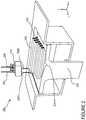
- FIG. 5is an exemplary cross-sectional view of a 3-D printed tooling shell 500 incorporating hollow structures and integrated channels.
- the tooling shellmay be composed of Invar, in whole or part, or of one or more different materials, depending on the application for which the tooling shell is suited and on the composition of the panel to be produced.
- the 3-D printed tooling shell 500 of FIG. 5can be modeled to include any number of complex geometries.
- the tooling shell 500may comprise a plurality of hollow sections 508 .
- These hollow sections 508are, more fundamentally, defined volumes of material vacancies within the tooling shell 500 . These defined volumes function to reduce an overall weight of the tooling shell 500 without sacrificing the amount of structural integrity required for the tooling shell 500 to be used in the molding process. While four hollow sections 508 are shown in this example, any number of hollow sections, including a single hollow section disposed substantially along an axis of the tooling shell 500 , may be used.
- the hollow sections 508may also be formed as one or more indentations in the material, such that at least one surface of the hollow section is exposed and such that the hollow section is not necessarily entirely within the tooling shell 500 .
- the sections 508may not be entirely empty but may, for maintenance of structural integrity or for other purposes, be filled with a substance that is substantially lighter than the base material(s) used to create the tooling shell.
- hollow sections 508is particularly advantageous in numerous contexts.
- One contextinvolves workers performing various stages of a manual molding process. Carrying the tooling shells and assembling the mold becomes easier, especially where, as is commonplace, the base materials from which the tooling shells are formed are otherwise heavy and impose burdens on the workers assembling and using the mold.
- the 3-D printed tooling shell 500comprises a plurality of integrated channels 502 , 504 , 506 . These channels constitute spaces within the tooling shell 500 that channel substances, gasses or heat to or from a surface 514 of the tooling shell 500 .
- channel 502is used for resin infusion
- channel 504is used to create a vacuum between the tooling shells to facilitate resin infusion from channel 502
- channel network 506is used to maintain a temperature of a material by transferring heat to or from surface 514 .
- Channel network 506may also be used to provide high heat conditions to an area near surface 514 for heating the materials or curing resin.
- Openings 510are provided for each of the channels 502 , 504 and 506 to transfer the substances or heat to or from surface 514 .
- openings 512shown at the lower surface 516 of the tooling shell 500 , may be coupled to devices such as a resin injector, vacuum chamber, or temperature control unit. It will be appreciated that the number, geometry and functions of the channels 502 , 504 and 506 can vary depending on the desired implementation.
- openings 510 and 512are shown at the upper surface 514 and lower surface 516 , respectively, of the 3-D printed tooling shell 500 , the openings may extend to different parts of the tooling shell 500 . For example, one or more of the openings 512 may be disposed on a side of the tooling shell.
- tooling shell 500would not be practical for many materials suitable for molding.
- many manufacturers of compositeslack the equipment necessary to cut and polish metal tools such as Invar, so the services of a tooling specialist may be required, adding to the manufacturers' cost.
- Invaris one of the most expensive metallic tooling materials and, especially for large parts, the sheer size and weight of the tools makes them difficult to handle. Additional parts including, for example, jigs and fixtures may be needed to add features to blocks of material during a conventional machining process, making the conventional techniques more complex and time consuming.
- the use of 3-D printing to render a tooling shell having a streamlined, preconfigured geometry with hollow sections for lightweight handling and molding features including integrated channel structuresmay impart substantial cost savings and provide significant benefits.
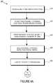
- FIG. 6is a flow diagram 600 illustrating an exemplary process for producing a 3D-printed tooling shell incorporating hollow structures and integrated channels.
- a 3-D printerreceives instructions for printing based on a data model as described in more detail above.
- the 3-D printerreceives one or more materials for use in printing the tooling shell, such as the material(s) constituting the tooling shell.
- the required materialsmay include support materials for use in temporarily providing support to the structure by supporting structure overhangs and providing a temporary fill for the volumes of the hollow sections and/or channels to be formed.
- the tooling shellis 3-D printed using any suitable printing technique.
- a sub-step 608may involve forming a plurality of channels disposed within the structure that will be used for resin infusion, vacuum generation, or heat transfer.
- a sub-step 610may involve the formation of one or more hollow sections to reduce an overall weight of the tooling shell, while not removing so much material as to compromise the tooling shell's overall structural integrity to perform the task it is designed to perform.
- a panelis molded with the tooling shell using any suitable technique, such as those described in this disclosure.
Landscapes
- Engineering & Computer Science (AREA)
- Manufacturing & Machinery (AREA)
- Mechanical Engineering (AREA)
- Chemical & Material Sciences (AREA)
- Materials Engineering (AREA)
- Moulding By Coating Moulds (AREA)
- Composite Materials (AREA)
Abstract
Description
| Temperature (° F.) | CTE (×10−6° F.−1) | ||
| 200 | 0.72 | ||
| 300 | 1.17 | ||
| 500 | 2.32 | ||
| 700 | 4.22 | ||
Claims (9)
Priority Applications (3)
| Application Number | Priority Date | Filing Date | Title |
|---|---|---|---|
| US15/430,395US10759090B2 (en) | 2017-02-10 | 2017-02-10 | Methods for producing panels using 3D-printed tooling shells |
| PCT/US2018/015235WO2018148025A1 (en) | 2017-02-10 | 2018-01-25 | Methods for producing panels using 3d-printed tooling shells |
| US16/884,808US11247367B2 (en) | 2017-02-10 | 2020-05-27 | 3D-printed tooling shells |
Applications Claiming Priority (1)
| Application Number | Priority Date | Filing Date | Title |
|---|---|---|---|
| US15/430,395US10759090B2 (en) | 2017-02-10 | 2017-02-10 | Methods for producing panels using 3D-printed tooling shells |
Related Child Applications (1)
| Application Number | Title | Priority Date | Filing Date |
|---|---|---|---|
| US16/884,808ContinuationUS11247367B2 (en) | 2017-02-10 | 2020-05-27 | 3D-printed tooling shells |
Publications (2)
| Publication Number | Publication Date |
|---|---|
| US20180229402A1 US20180229402A1 (en) | 2018-08-16 |
| US10759090B2true US10759090B2 (en) | 2020-09-01 |
Family
ID=63106636
Family Applications (2)
| Application Number | Title | Priority Date | Filing Date |
|---|---|---|---|
| US15/430,395Active2037-12-03US10759090B2 (en) | 2017-02-10 | 2017-02-10 | Methods for producing panels using 3D-printed tooling shells |
| US16/884,808ActiveUS11247367B2 (en) | 2017-02-10 | 2020-05-27 | 3D-printed tooling shells |
Family Applications After (1)
| Application Number | Title | Priority Date | Filing Date |
|---|---|---|---|
| US16/884,808ActiveUS11247367B2 (en) | 2017-02-10 | 2020-05-27 | 3D-printed tooling shells |
Country Status (2)
| Country | Link |
|---|---|
| US (2) | US10759090B2 (en) |
| WO (1) | WO2018148025A1 (en) |
Cited By (2)
| Publication number | Priority date | Publication date | Assignee | Title |
|---|---|---|---|---|
| US20220055306A1 (en)* | 2019-04-29 | 2022-02-24 | Hewlett-Packard Development Company, L.P. | Cooling unit with a self-locking latch mechanism |
| US11731320B2 (en)* | 2017-11-27 | 2023-08-22 | Essentium Ipco, Llc | Tool assembly for manufacturing parts and a method of producing a tooling assembly |
Families Citing this family (7)
| Publication number | Priority date | Publication date | Assignee | Title |
|---|---|---|---|---|
| US10493525B2 (en)* | 2016-05-10 | 2019-12-03 | Honeywell Federal Manufacturing & Technologies, Llc | Lifting and removal device for additive manufacturing system |
| US10836120B2 (en)* | 2018-08-27 | 2020-11-17 | Divergent Technologies, Inc . | Hybrid composite structures with integrated 3-D printed elements |
| WO2020159835A1 (en)* | 2019-01-28 | 2020-08-06 | Smith William E | Mechanical systems to assemble or deploy pre-stressed structures |
| WO2021026096A1 (en)* | 2019-08-02 | 2021-02-11 | Airtech International, Inc. | Adjustable cte polymer compositions for extrusion and additive manufacturing processes |
| US20250074017A1 (en) | 2021-12-27 | 2025-03-06 | Tusas- Turk Havacilik Ve Uzay Sanayii Anonim Sirketi | Production system |
| CN115742360A (en)* | 2022-11-08 | 2023-03-07 | 株洲瀚捷航空科技有限公司 | Process for manufacturing special-shaped product by using carbon fiber synthetic resin |
| US20240278511A1 (en) | 2023-02-21 | 2024-08-22 | Embraer S.A. | Hybrid tooling structures of additively manufactured thermoplastics reinforced with rigid metal supports and methods for the design and manufacture thereof |
Citations (306)
| Publication number | Priority date | Publication date | Assignee | Title |
|---|---|---|---|---|
| US5203226A (en) | 1990-04-17 | 1993-04-20 | Toyoda Gosei Co., Ltd. | Steering wheel provided with luminous display device |
| WO1996036525A1 (en) | 1995-05-19 | 1996-11-21 | Edag Engineering + Design Ag | Process for automatically fitting a motor vehicle body component |
| WO1996036455A1 (en) | 1995-05-16 | 1996-11-21 | Edag Engineering + Design Ag | Device for feeding welding bolts to a welding gun |
| WO1996038260A1 (en) | 1995-05-30 | 1996-12-05 | Edag Engineering + Design Ag | Container changer |
| US5742385A (en) | 1996-07-16 | 1998-04-21 | The Boeing Company | Method of airplane interiors assembly using automated rotating laser technology |
| US5990444A (en) | 1995-10-30 | 1999-11-23 | Costin; Darryl J. | Laser method and system of scribing graphics |
| US6010155A (en) | 1996-12-31 | 2000-01-04 | Dana Corporation | Vehicle frame assembly and method for manufacturing same |
| US6096249A (en) | 1996-12-05 | 2000-08-01 | Teijin Limited | Method for molding fiber aggregate |
| US6140602A (en) | 1997-04-29 | 2000-10-31 | Technolines Llc | Marking of fabrics and other materials using a laser |
| US6252196B1 (en) | 1996-10-11 | 2001-06-26 | Technolines Llc | Laser method of scribing graphics |
| US6250533B1 (en) | 1999-02-18 | 2001-06-26 | Edag Engineering & Design Ag | Clamping device for use in motor vehicle production lines and production line having such a clamping device |
| US6318642B1 (en) | 1999-12-22 | 2001-11-20 | Visteon Global Tech., Inc | Nozzle assembly |
| US6354361B1 (en) | 1995-10-31 | 2002-03-12 | Massachusetts Institute Of Technology | Tooling having advantageously located heat transfer channels |
| US6365057B1 (en) | 1999-11-01 | 2002-04-02 | Bmc Industries, Inc. | Circuit manufacturing using etched tri-metal media |
| US6391251B1 (en) | 1999-07-07 | 2002-05-21 | Optomec Design Company | Forming structures from CAD solid models |
| US6409930B1 (en) | 1999-11-01 | 2002-06-25 | Bmc Industries, Inc. | Lamination of circuit sub-elements while assuring registration |
| US6468439B1 (en) | 1999-11-01 | 2002-10-22 | Bmc Industries, Inc. | Etching of metallic composite articles |
| WO2003024641A1 (en) | 2001-08-31 | 2003-03-27 | Edag Engineering + Design Aktiengesellschaft | Roller folding head and method for folding a flange |
| US6554345B2 (en) | 1997-10-23 | 2003-04-29 | Ssab Hardtech Ab | Lightweight beam |
| US6585151B1 (en) | 2000-05-23 | 2003-07-01 | The Regents Of The University Of Michigan | Method for producing microporous objects with fiber, wire or foil core and microporous cellular objects |
| US6644721B1 (en) | 2002-08-30 | 2003-11-11 | Ford Global Technologies, Llc | Vehicle bed assembly |
| US20040135294A1 (en) | 2001-06-11 | 2004-07-15 | The Boeing Company | Resin infusion mold tool system and vacuum assisted resin transfer molding with subsequent pressure bleed |
| US6811744B2 (en) | 1999-07-07 | 2004-11-02 | Optomec Design Company | Forming structures from CAD solid models |
| WO2004108343A1 (en) | 2003-06-05 | 2004-12-16 | Erwin Martin Heberer | Device for shielding coherent electromagnetic radiation and laser booth provided with such a device |
| US6866497B2 (en) | 2001-06-13 | 2005-03-15 | Kabushiki Kaisha Tokai Rika Denki Seisakusho | Molding apparatus having a projecting bulge located in a die half |
| US6919035B1 (en) | 2001-05-18 | 2005-07-19 | Ensci Inc. | Metal oxide coated polymer substrates |
| US6926970B2 (en) | 2001-11-02 | 2005-08-09 | The Boeing Company | Apparatus and method for forming weld joints having compressive residual stress patterns |
| WO2005093773A1 (en) | 2004-03-25 | 2005-10-06 | Audi Ag | System comprising an automotive fuse and an a/d converter |
| US20060108783A1 (en) | 2004-11-24 | 2006-05-25 | Chi-Mou Ni | Structural assembly for vehicles and method of making same |
| WO2007003375A1 (en) | 2005-06-30 | 2007-01-11 | Edag Engineering + Design Ag | Method and device for joining joining structures, particularly during the assembly of vehicle components |
| WO2007110235A1 (en) | 2006-03-28 | 2007-10-04 | Edag Gmbh & Co. Kgaa | Clamping device for holding and clamping components |
| WO2007110236A1 (en) | 2006-03-28 | 2007-10-04 | Edag Gmbh & Co. Kgaa | Clamping device for holding and clamping components |
| WO2007128586A2 (en) | 2006-05-10 | 2007-11-15 | Edag Gmbh & Co. Kgaa | Energy beam brazing or welding of components |
| WO2008019847A1 (en) | 2006-08-18 | 2008-02-21 | Fft Edag Produktionssysteme Gmbh & Co. Kg | Monitoring device for a laser machining device |
| US7344186B1 (en) | 2007-01-08 | 2008-03-18 | Ford Global Technologies, Llc | A-pillar structure for an automotive vehicle |
| WO2008068314A2 (en) | 2006-12-08 | 2008-06-12 | Edag Gmbh & Co. Kgaa | Flanging hand tool |
| WO2008086994A1 (en) | 2007-01-15 | 2008-07-24 | Edag Gmbh & Co. Kgaa | Sheet-metal composite, method for joining sheets and joining device |
| WO2008087024A1 (en) | 2007-01-18 | 2008-07-24 | Toyota Motor Corporation | Composite of sheet metal parts |
| WO2008107130A1 (en) | 2007-03-02 | 2008-09-12 | Edag Gmbh & Co. Kgaa | Automobile with facilitated passenger exit |
| WO2008138503A1 (en) | 2007-05-11 | 2008-11-20 | Edag Gmbh & Co. Kgaa | Crimping components in series production having short cycle times |
| WO2008145396A1 (en) | 2007-06-01 | 2008-12-04 | Edag Gmbh & Co. Kgaa | Edge curling tool |
| US7500373B2 (en) | 2004-09-24 | 2009-03-10 | Edag Gmbh & Co. Kgaa | Flanging device and flanging method with component protection |
| WO2009083609A2 (en) | 2008-01-03 | 2009-07-09 | Edag Gmbh & Co. Kgaa | Method for bending a workpiece |
| US20090189320A1 (en) | 2008-01-28 | 2009-07-30 | North Carolina Agricultural And Technical State University | Heat vacuum assisted resin transfer molding processes for manufacturing composite materials |
| WO2009098285A1 (en) | 2008-02-07 | 2009-08-13 | Edag Gmbh & Co. Kgaa | Rotating table |
| WO2009112520A1 (en) | 2008-03-11 | 2009-09-17 | Edag Gmbh & Co. Kgaa | Tool, system and method for the manufacture of a cable harness |
| WO2009135938A1 (en) | 2008-05-09 | 2009-11-12 | Edag Gmbh & Co. Kgaa | Method and tool for producing a fixed connection to components joined in a form-fitted manner |
| WO2009140977A1 (en) | 2008-05-21 | 2009-11-26 | Edag Gmbh & Co. Kgaa | Clamping frame-less joining of components |
| US7637134B2 (en) | 2005-01-31 | 2009-12-29 | Edag Gmbh & Co. Kgaa | Flanging with a leading and following flanging die |
| US7710347B2 (en) | 2007-03-13 | 2010-05-04 | Raytheon Company | Methods and apparatus for high performance structures |
| US7716802B2 (en) | 2006-01-03 | 2010-05-18 | The Boeing Company | Method for machining using sacrificial supports |
| US7745293B2 (en) | 2004-06-14 | 2010-06-29 | Semiconductor Energy Laboratory Co., Ltd | Method for manufacturing a thin film transistor including forming impurity regions by diagonal doping |
| US7766123B2 (en) | 2006-03-29 | 2010-08-03 | Yamaha Hatsudoki Kabushiki Kaisha | Vehicle exhaust system |
| WO2010125058A1 (en) | 2009-04-27 | 2010-11-04 | Edag Gmbh & Co. Kgaa | Clamping device, system, and method for processing changing component types |
| WO2010125057A2 (en) | 2009-04-27 | 2010-11-04 | Edag Gmbh & Co. Kgaa | Robot support |
| US7852388B2 (en) | 2006-05-23 | 2010-12-14 | Panasonic Corporation | Imaging device |
| WO2010142703A2 (en) | 2009-06-09 | 2010-12-16 | Edag Gmbh & Co. Kgaa | Method and tool for edging a workpiece |
| US7908922B2 (en) | 2008-01-24 | 2011-03-22 | Delphi Technologies, Inc. | Silicon integrated angular rate sensor |
| WO2011032533A1 (en) | 2009-09-15 | 2011-03-24 | Edag Gmbh & Co. Kgaa | Vehicle body component composed of an exterior element and a fibre-reinforced plastic structural component connected to the rear side of said exterior element |
| US7951324B2 (en) | 2006-09-14 | 2011-05-31 | Ibiden Co., Ltd. | Method for manufacturing honeycomb structure |
| US8108982B2 (en)* | 2005-01-18 | 2012-02-07 | Floodcooling Technologies, L.L.C. | Compound mold tooling for controlled heat transfer |
| US8163077B2 (en) | 2005-09-28 | 2012-04-24 | Yissum Research Development Company Of The Hebrew University Of Jerusalem | Ink providing etch-like effect for printing on ceramic surfaces |
| US8286236B2 (en) | 2007-12-21 | 2012-10-09 | The Invention Science Fund I, Llc | Manufacturing control system |
| US8289352B2 (en) | 2010-07-15 | 2012-10-16 | HJ Laboratories, LLC | Providing erasable printing with nanoparticles |
| US8297096B2 (en) | 2007-07-20 | 2012-10-30 | Nippon Steel Corporation | Method for hydroforming and hydroformed product |
| US8354170B1 (en) | 2009-10-06 | 2013-01-15 | Hrl Laboratories, Llc | Elastomeric matrix composites |
| US8383028B2 (en) | 2008-11-13 | 2013-02-26 | The Boeing Company | Method of manufacturing co-molded inserts |
| US8429754B2 (en) | 2007-12-21 | 2013-04-23 | The Invention Science Fund I, Llc | Control technique for object production rights |
| US8437513B1 (en) | 2012-08-10 | 2013-05-07 | EyeVerify LLC | Spoof detection for biometric authentication |
| US8444903B2 (en) | 2007-07-13 | 2013-05-21 | The Boeing Company | Method of fabricating three dimensional printed part |
| US8452073B2 (en) | 2009-04-08 | 2013-05-28 | The United States Of America As Represented By The Administrator Of The National Aeronautics And Space Administration | Closed-loop process control for electron beam freeform fabrication and deposition processes |
| US8599301B2 (en) | 2006-04-17 | 2013-12-03 | Omnivision Technologies, Inc. | Arrayed imaging systems having improved alignment and associated methods |
| US8606540B2 (en) | 2009-11-10 | 2013-12-10 | Projectionworks, Inc. | Hole measurement apparatuses |
| US8610761B2 (en) | 2009-11-09 | 2013-12-17 | Prohectionworks, Inc. | Systems and methods for optically projecting three-dimensional text, images and/or symbols onto three-dimensional objects |
| WO2014016437A1 (en) | 2012-07-27 | 2014-01-30 | Fft Edag Produktionssysteme Gmbh & Co. Kg | Hemming press |
| US8678060B2 (en) | 2011-03-04 | 2014-03-25 | Fft Edag Produktionssysteme Gmbh & Co. Kg | Joining surface treatment device and method |
| US8686997B2 (en) | 2009-12-18 | 2014-04-01 | Sassault Systemes | Method and system for composing an assembly |
| US8694284B2 (en) | 2010-04-02 | 2014-04-08 | Dassault Systemes | Part modeled by parallel geodesic curves |
| US8752166B2 (en) | 2007-12-21 | 2014-06-10 | The Invention Science Fund I, Llc | Security-activated operational components |
| US20140159267A1 (en)* | 2011-07-28 | 2014-06-12 | Plasan Carbon Composites, Inc. | System and method for forming composite articles |
| US8755923B2 (en) | 2009-12-07 | 2014-06-17 | Engineering Technology Associates, Inc. | Optimization system |
| US8818771B2 (en) | 2010-06-21 | 2014-08-26 | Johan Gielis | Computer implemented tool box systems and methods |
| US20140277669A1 (en) | 2013-03-15 | 2014-09-18 | Sikorsky Aircraft Corporation | Additive topology optimized manufacturing for multi-functional components |
| US8873238B2 (en) | 2012-06-11 | 2014-10-28 | The Boeing Company | Chassis system and method for holding and protecting electronic modules |
| WO2014187720A1 (en) | 2013-05-22 | 2014-11-27 | Fft Edag Produktionssysteme Gmbh & Co. Kg | Joining a workpiece with a concealed joint seam |
| WO2014195340A1 (en) | 2013-06-07 | 2014-12-11 | Fft Produktionssyteme Gmbh & Co. Kg | Device for use in the handling of a load and method for producing such a device |
| US20150041098A1 (en) | 2013-08-06 | 2015-02-12 | Wisys Technology Foundation, Inc. | 3-D Printed Casting Shell And Method Of Manufacture |
| US20150044430A1 (en)* | 2012-11-02 | 2015-02-12 | The Boeing Company | Wrinkle diffuser system for composites |
| US8978535B2 (en) | 2010-08-11 | 2015-03-17 | Massachusetts Institute Of Technology | Articulating protective system for resisting mechanical loads |
| US9071436B2 (en) | 2007-12-21 | 2015-06-30 | The Invention Science Fund I, Llc | Security-activated robotic system |
| US9101979B2 (en) | 2011-10-31 | 2015-08-11 | California Institute Of Technology | Methods for fabricating gradient alloy articles with multi-functional properties |
| US9128476B2 (en) | 2007-12-21 | 2015-09-08 | The Invention Science Fund I, Llc | Secure robotic operational system |
| US9126365B1 (en) | 2013-03-22 | 2015-09-08 | Markforged, Inc. | Methods for composite filament fabrication in three dimensional printing |
| US9138924B2 (en) | 2014-01-06 | 2015-09-22 | Prior Company Limited | Manufacturing method of decorated molding article and manufacturing method of decorated film |
| US9149988B2 (en) | 2013-03-22 | 2015-10-06 | Markforged, Inc. | Three dimensional printing |
| US9156205B2 (en) | 2013-03-22 | 2015-10-13 | Markforged, Inc. | Three dimensional printer with composite filament fabrication |
| US9186848B2 (en) | 2013-03-22 | 2015-11-17 | Markforged, Inc. | Three dimensional printing of composite reinforced structures |
| WO2015193331A1 (en) | 2014-06-17 | 2015-12-23 | Fft Produktionssysteme Gmbh & Co. Kg | Segmented retaining plate for a workpiece |
| US9244986B2 (en) | 2013-01-11 | 2016-01-26 | Buckyball Mobile, Inc. | Method and system for interactive geometric representations, configuration and control of data |
| US9248611B2 (en) | 2013-10-07 | 2016-02-02 | David A. Divine | 3-D printed packaging |
| US9254535B2 (en) | 2014-06-20 | 2016-02-09 | Velo3D, Inc. | Apparatuses, systems and methods for three-dimensional printing |
| US9266566B2 (en) | 2014-04-09 | 2016-02-23 | Hyundai Motor Company | Front body member for vehicle |
| US9269022B2 (en) | 2013-04-11 | 2016-02-23 | Digimarc Corporation | Methods for object recognition and related arrangements |
| US9329020B1 (en) | 2013-01-02 | 2016-05-03 | Lockheed Martin Corporation | System, method, and computer program product to provide wireless sensing based on an aggregate magnetic field reading |
| US9389315B2 (en) | 2012-12-19 | 2016-07-12 | Basf Se | Detector comprising a transversal optical sensor for detecting a transversal position of a light beam from an object and a longitudinal optical sensor sensing a beam cross-section of the light beam in a sensor region |
| WO2016116414A1 (en) | 2015-01-19 | 2016-07-28 | Fft Produktionssysteme Gmbh & Co. Kg | Flanging system, flanging unit and flanging method for autonomous flanging |
| US9457514B2 (en) | 2012-03-08 | 2016-10-04 | Klaus Schwärzler | Method and device for layered buildup of a shaped element |
| US9469057B2 (en) | 2012-05-18 | 2016-10-18 | 3D Systems, Inc. | Support structures and deposition techniques for 3D printing |
| US9481402B1 (en) | 2015-05-26 | 2016-11-01 | Honda Motor Co., Ltd. | Methods and apparatus for supporting vehicle components |
| US9486960B2 (en) | 2014-12-19 | 2016-11-08 | Palo Alto Research Center Incorporated | System for digital fabrication of graded, hierarchical material structures |
| US9502993B2 (en) | 2011-02-07 | 2016-11-22 | Ion Geophysical Corporation | Method and apparatus for sensing signals |
| US9525262B2 (en) | 2011-08-04 | 2016-12-20 | Martin A. Stuart | Slab laser and amplifier and method of use |
| US20160368585A1 (en) | 2015-06-19 | 2016-12-22 | Airbus Operations (Sas) | Process for the manufacture of a fuselage panel by overmolding and fuselage panel so obtained |
| US9533526B1 (en) | 2012-06-15 | 2017-01-03 | Joel Nevins | Game object advances for the 3D printing entertainment industry |
| US9557856B2 (en) | 2013-08-19 | 2017-01-31 | Basf Se | Optical detector |
| US9555580B1 (en) | 2013-03-21 | 2017-01-31 | Temper Ip, Llc. | Friction stir welding fastener |
| US9555315B2 (en) | 2013-12-05 | 2017-01-31 | Aaron Benjamin Aders | Technologies for transportation |
| US9566742B2 (en) | 2012-04-03 | 2017-02-14 | Massachusetts Institute Of Technology | Methods and apparatus for computer-assisted spray foam fabrication |
| US9566758B2 (en) | 2010-10-19 | 2017-02-14 | Massachusetts Institute Of Technology | Digital flexural materials |
| WO2017036461A1 (en) | 2015-09-04 | 2017-03-09 | Edag Engineering Gmbh | Mobile communication device and software code, and traffic entity |
| US9595795B2 (en) | 2014-12-09 | 2017-03-14 | Te Connectivity Corporation | Header assembly |
| US9597843B2 (en) | 2014-05-15 | 2017-03-21 | The Boeing Company | Method and apparatus for layup tooling |
| US9600929B1 (en) | 2014-12-01 | 2017-03-21 | Ngrain (Canada) Corporation | System, computer-readable medium and method for 3D-differencing of 3D voxel models |
| US9609755B2 (en) | 2013-01-17 | 2017-03-28 | Hewlett-Packard Development Company, L.P. | Nanosized particles deposited on shaped surface geometries |
| US9610737B2 (en) | 2015-03-04 | 2017-04-04 | Ebert Composites Corporation | 3D thermoplastic composite pultrusion system and method |
| US9611667B2 (en) | 2015-05-05 | 2017-04-04 | West Virginia University | Durable, fire resistant, energy absorbing and cost-effective strengthening systems for structural joints and members |
| US9626489B2 (en) | 2013-03-13 | 2017-04-18 | Intertrust Technologies Corporation | Object rendering systems and methods |
| US9626487B2 (en) | 2007-12-21 | 2017-04-18 | Invention Science Fund I, Llc | Security-activated production device |
| US20170113344A1 (en) | 2015-10-21 | 2017-04-27 | Fft Produktionssysteme Gmbh & Co. Kg | Absolute Robot-Assisted Positioning Method |
| US9643361B2 (en) | 2014-05-27 | 2017-05-09 | Jian Liu | Method and apparatus for three-dimensional additive manufacturing with a high energy high power ultrafast laser |
| US9665182B2 (en) | 2013-08-19 | 2017-05-30 | Basf Se | Detector for determining a position of at least one object |
| US9662840B1 (en) | 2015-11-06 | 2017-05-30 | Velo3D, Inc. | Adept three-dimensional printing |
| US9672389B1 (en) | 2012-06-26 | 2017-06-06 | The Mathworks, Inc. | Generic human machine interface for a graphical model |
| US9672550B2 (en) | 2010-09-24 | 2017-06-06 | Amazon Technologies, Inc. | Fulfillment of orders for items using 3D manufacturing on demand |
| US9684919B2 (en) | 2010-09-24 | 2017-06-20 | Amazon Technologies, Inc. | Item delivery using 3D manufacturing on demand |
| US9688032B2 (en) | 2013-07-01 | 2017-06-27 | GM Global Technology Operations LLC | Thermoplastic component repair |
| US9690286B2 (en) | 2012-06-21 | 2017-06-27 | Massachusetts Institute Of Technology | Methods and apparatus for digital material skins |
| US9703896B2 (en) | 2014-03-11 | 2017-07-11 | Microsoft Technology Licensing, Llc | Generation of custom modular objects |
| US9718434B2 (en) | 2015-01-21 | 2017-08-01 | GM Global Technology Operations LLC | Tunable energy absorbers |
| US9718302B2 (en) | 2015-09-22 | 2017-08-01 | The Boeing Company | Decorative laminate with non-visible light activated material and system and method for using the same |
| US9724877B2 (en) | 2013-06-23 | 2017-08-08 | Robert A. Flitsch | Methods and apparatus for mobile additive manufacturing of advanced structures and roadways |
| US9725178B2 (en) | 2015-05-08 | 2017-08-08 | Raymond R M Wang | Airflow modification apparatus and method |
| US9731773B2 (en) | 2015-03-11 | 2017-08-15 | Caterpillar Inc. | Node for a space frame |
| US9731730B2 (en) | 2014-09-24 | 2017-08-15 | Holland Lp | Grating connector and spacer apparatus, system, and methods of using the same |
| US9741954B2 (en) | 2013-06-13 | 2017-08-22 | Basf Se | Optical detector and method for manufacturing the same |
| US9765226B2 (en) | 2014-03-27 | 2017-09-19 | Disney Enterprises, Inc. | Ultraviolet printing with luminosity control |
| US9764415B2 (en) | 2013-03-15 | 2017-09-19 | The United States Of America As Represented By The Administrator Of Nasa | Height control and deposition measurement for the electron beam free form fabrication (EBF3) process |
| US9773393B2 (en) | 2015-10-07 | 2017-09-26 | Michael D. Velez | Flow alarm |
| US9782936B2 (en) | 2014-03-01 | 2017-10-10 | Anguleris Technologies, Llc | Method and system for creating composite 3D models for building information modeling (BIM) |
| US9783977B2 (en) | 2015-11-20 | 2017-10-10 | University Of South Florida | Shape-morphing space frame apparatus using unit cell bistable elements |
| US9783324B2 (en) | 2014-08-26 | 2017-10-10 | The Boeing Company | Vessel insulation assembly |
| US9789548B2 (en) | 2015-08-31 | 2017-10-17 | The Boeing Company | Geodesic structure forming systems and methods |
| US9789922B2 (en) | 2014-12-18 | 2017-10-17 | The Braun Corporation | Modified door opening of a motorized vehicle for accommodating a ramp system and method thereof |
| US9796137B2 (en) | 2015-06-08 | 2017-10-24 | The Boeing Company | Additive manufacturing methods |
| US9802108B2 (en) | 2013-12-05 | 2017-10-31 | Aaron Benjamin Aders | Technologies for transportation |
| US9809977B2 (en) | 2015-05-07 | 2017-11-07 | Massachusetts Institute Of Technology | Digital material assembly by passive means and modular isotropic lattice extruder system |
| US9817922B2 (en) | 2014-03-01 | 2017-11-14 | Anguleris Technologies, Llc | Method and system for creating 3D models from 2D data for building information modeling (BIM) |
| US9818071B2 (en) | 2007-12-21 | 2017-11-14 | Invention Science Fund I, Llc | Authorization rights for operational components |
| US9823143B2 (en) | 2013-10-07 | 2017-11-21 | United Technologies Corporation | Additively grown enhanced impact resistance features for improved structure and joint protection |
| US9821339B2 (en) | 2014-12-19 | 2017-11-21 | Palo Alto Research Center Incorporated | System and method for digital fabrication of graded, hierarchical material structures |
| US9829564B2 (en) | 2013-06-13 | 2017-11-28 | Basf Se | Detector for optically detecting at least one longitudinal coordinate of one object by determining a number of illuminated pixels |
| US20170341309A1 (en) | 2016-05-24 | 2017-11-30 | Airbus Operations Gmbh | System and method for handling a component |
| US9846933B2 (en) | 2015-11-16 | 2017-12-19 | General Electric Company | Systems and methods for monitoring components |
| US9854828B2 (en) | 2014-09-29 | 2018-01-02 | William Langeland | Method, system and apparatus for creating 3D-printed edible objects |
| US9858604B2 (en) | 2010-09-24 | 2018-01-02 | Amazon Technologies, Inc. | Vendor interface for item delivery via 3D manufacturing on demand |
| US9862834B2 (en) | 2014-09-09 | 2018-01-09 | Graphene Platform Corporation | Composite reinforcing material and molding material |
| US9863885B2 (en) | 2015-10-07 | 2018-01-09 | The Regents Of The University Of Californa | Graphene-based multi-modal sensors |
| US9870629B2 (en) | 2008-06-20 | 2018-01-16 | New Bis Safe Luxco S.À R.L | Methods, apparatus and systems for data visualization and related applications |
| US9879981B1 (en) | 2016-12-02 | 2018-01-30 | General Electric Company | Systems and methods for evaluating component strain |
| US9884663B2 (en) | 2014-05-16 | 2018-02-06 | Divergent Technologies, Inc. | Modular formed nodes for vehicle chassis and their methods of use |
| US9898776B2 (en) | 2010-09-24 | 2018-02-20 | Amazon Technologies, Inc. | Providing services related to item delivery via 3D manufacturing on demand |
| US9914150B2 (en) | 2010-09-22 | 2018-03-13 | Hexagon Technology Center Gmbh | Graphical application system |
| US9919360B2 (en) | 2016-02-18 | 2018-03-20 | Velo3D, Inc. | Accurate three-dimensional printing |
| US9933092B2 (en) | 2016-08-18 | 2018-04-03 | Deflecto, LLC | Tubular structures and knurling systems and methods of manufacture and use thereof |
| US9933031B2 (en) | 2015-11-21 | 2018-04-03 | Ats Mer, Llc | Systems and methods for forming a layer onto a surface of a solid substrate and products formed thereby |
| US9957031B2 (en) | 2015-08-31 | 2018-05-01 | The Boeing Company | Systems and methods for manufacturing a tubular structure |
| US9963978B2 (en) | 2015-06-09 | 2018-05-08 | Ebert Composites Corporation | 3D thermoplastic composite pultrusion system and method |
| US9962767B2 (en) | 2015-12-10 | 2018-05-08 | Velo3D, Inc. | Apparatuses for three-dimensional printing |
| US9976063B2 (en) | 2016-03-11 | 2018-05-22 | The Boeing Company | Polyarylether ketone imide sulfone adhesives |
| US9988136B2 (en) | 2014-11-06 | 2018-06-05 | Airbus Operations Gmbh | Structural component and method for producing a structural component |
| US9996890B1 (en) | 2017-07-14 | 2018-06-12 | Synapse Technology Corporation | Detection of items |
| US9996945B1 (en) | 2016-12-12 | 2018-06-12 | Fyusion, Inc. | Live augmented reality guides |
| US10006156B2 (en) | 2014-03-21 | 2018-06-26 | Goodrich Corporation | Systems and methods for calculated tow fiber angle |
| US10013777B2 (en) | 2013-11-25 | 2018-07-03 | 7D Surgical Inc. | System and method for generating partial surface from volumetric data for registration to surface topology image data |
| US10015908B2 (en) | 2016-12-07 | 2018-07-03 | The Boeing Company | System and method for cryogenic cooling of electromagnetic induction filter |
| US10011089B2 (en) | 2011-12-31 | 2018-07-03 | The Boeing Company | Method of reinforcement for additive manufacturing |
| US10011685B2 (en) | 2016-03-11 | 2018-07-03 | The Boeing Company | Polyarylether ketone imide adhesives |
| US10018576B2 (en) | 2014-04-09 | 2018-07-10 | Texas Instruments Incorporated | Material detection and analysis using a dielectric waveguide |
| US10016852B2 (en) | 2014-11-13 | 2018-07-10 | The Boeing Company | Apparatuses and methods for additive manufacturing |
| US10017384B1 (en) | 2017-01-06 | 2018-07-10 | Nanoclear Technologies Inc. | Property control of multifunctional surfaces |
| US10022912B2 (en) | 2015-11-13 | 2018-07-17 | GM Global Technology Operations LLC | Additive manufacturing of a unibody vehicle |
| US10027376B2 (en) | 2015-09-11 | 2018-07-17 | Texas Instruments Incorporated | Guided near field communication for short range data communication |
| US10022792B2 (en) | 2014-11-13 | 2018-07-17 | The Indian Institute of Technology | Process of dough forming of polymer-metal blend suitable for shape forming |
| US10029415B2 (en) | 2012-08-16 | 2018-07-24 | Stratasys, Inc. | Print head nozzle for use with additive manufacturing system |
| US10040239B2 (en) | 2015-03-20 | 2018-08-07 | Chevron Phillips Chemical Company Lp | System and method for writing an article of manufacture into bulk material |
| US10046412B2 (en) | 2013-08-02 | 2018-08-14 | Rolls-Royce Plc | Method of manufacturing a component |
| US10048769B2 (en) | 2015-11-18 | 2018-08-14 | Ted Selker | Three-dimensional computer-aided-design system user interface |
| US20180229401A1 (en)* | 2017-02-10 | 2018-08-16 | Divergent Technologies, Inc. | 3d-printed tooling and methods for producing same |
| US10055536B2 (en) | 2012-07-30 | 2018-08-21 | Materialise, Nv | Systems and methods for forming and utilizing bending maps for object design |
| US10052712B2 (en) | 2013-08-02 | 2018-08-21 | Rolls-Royce Plc | Method of manufacturing a component |
| US10052820B2 (en) | 2013-09-13 | 2018-08-21 | Made In Space, Inc. | Additive manufacturing of extended structures |
| US10065367B2 (en) | 2015-03-20 | 2018-09-04 | Chevron Phillips Chemical Company Lp | Phonon generation in bulk material for manufacturing |
| US10068316B1 (en) | 2017-03-03 | 2018-09-04 | Fyusion, Inc. | Tilts as a measure of user engagement for multiview digital media representations |
| US10065361B2 (en) | 2017-02-07 | 2018-09-04 | Thermwood Corporation | Apparatus and method for printing long composite thermoplastic parts on a dual gantry machine during additive manufacturing |
| US20180250889A1 (en)* | 2017-03-01 | 2018-09-06 | Divergent Technologies, Inc. | 3-d printing using spray forming |
| US10074128B2 (en) | 2014-06-08 | 2018-09-11 | Shay C. Colson | Pre-purchase mechanism for autonomous vehicles |
| US10072179B2 (en) | 2013-04-26 | 2018-09-11 | Dsm Ip Assets B.V. | Vinyl functionalized urethane resins for powder coating compositions |
| US10076876B2 (en) | 2013-03-22 | 2018-09-18 | Markforged, Inc. | Three dimensional printing |
| US10081140B2 (en) | 2014-10-29 | 2018-09-25 | The Boeing Company | Apparatus for and method of compaction of a prepreg |
| US10081431B2 (en) | 2013-12-20 | 2018-09-25 | Airbus Operations Gmbh | Load bearing element and a method for manufacturing a load bearing element |
| US10086568B2 (en) | 2013-10-21 | 2018-10-02 | Made In Space, Inc. | Seamless scanning and production devices and methods |
| US10087556B2 (en) | 2013-11-21 | 2018-10-02 | Sabic Global Technologies B.V. | Reduced density article |
| US10087320B2 (en) | 2017-02-17 | 2018-10-02 | Polydrop, Llc | Conductive polymer-matrix compositions and uses thereof |
| US10108766B2 (en) | 2014-11-05 | 2018-10-23 | The Boeing Company | Methods and apparatus for analyzing fatigue of a structure and optimizing a characteristic of the structure based on the fatigue analysis |
| US10118579B2 (en) | 2015-01-28 | 2018-11-06 | Jaguar Land Rover Limited | Impact energy absorbing device for a vehicle |
| US10124546B2 (en) | 2015-03-04 | 2018-11-13 | Ebert Composites Corporation | 3D thermoplastic composite pultrusion system and method |
| US10124570B2 (en) | 2015-07-31 | 2018-11-13 | The Boeing Company | Methods for additively manufacturing composite parts |
| US10138354B2 (en) | 2014-12-10 | 2018-11-27 | Fraunhofer-Gesellschaft zur Förderung der angewandten Forschung e.V. | Polymer composition having delayed crystallization behavior, additive composition that influences the crystallization behavior, method for reducing the crystallization point and/or the crystallization speed, and use of an additive composition |
| US10137500B2 (en) | 2013-08-02 | 2018-11-27 | Rolls-Royce Plc | Method of manufacturing a component |
| US10144126B2 (en) | 2015-08-26 | 2018-12-04 | Airbus Operations Gmbh | Robot system and method of operating a robot system |
| US10152661B2 (en) | 2014-08-11 | 2018-12-11 | Brian Kieser | Structurally encoded component and method of manufacturing structurally encoded component |
| US20180363691A1 (en)* | 2017-06-19 | 2018-12-20 | Divergent Technologies, Inc. | 3-d-printed components including fasteners and methods for producing same |
| US10161021B2 (en) | 2016-04-20 | 2018-12-25 | Arconic Inc. | FCC materials of aluminum, cobalt and nickel, and products made therefrom |
| US10160278B2 (en) | 2014-12-16 | 2018-12-25 | Aktv8 LLC | System and method for vehicle stabilization |
| US10171578B1 (en) | 2017-06-29 | 2019-01-01 | Texas Instruments Incorporated | Tapered coax launch structure for a near field communication system |
| US10178800B2 (en) | 2017-03-30 | 2019-01-08 | Honeywell International Inc. | Support structure for electronics having fluid passageway for convective heat transfer |
| US10173255B2 (en) | 2016-06-09 | 2019-01-08 | Divergent Technologies, Inc. | Systems and methods for arc and node design and manufacture |
| US10179640B2 (en) | 2016-08-24 | 2019-01-15 | The Boeing Company | Wing and method of manufacturing |
| US10200677B2 (en) | 2017-05-22 | 2019-02-05 | Fyusion, Inc. | Inertial measurement unit progress estimation |
| US10197338B2 (en) | 2013-08-22 | 2019-02-05 | Kevin Hans Melsheimer | Building system for cascading flows of matter and energy |
| US10196539B2 (en) | 2013-11-21 | 2019-02-05 | Dsm Ip Assets B.V. | Thermosetting powder coating compositions comprising methyl-substituted benzoyl peroxide |
| US10202673B2 (en) | 2016-04-20 | 2019-02-12 | Arconic Inc. | Fcc materials of aluminum, cobalt, iron and nickel, and products made therefrom |
| US10201941B2 (en) | 2015-07-31 | 2019-02-12 | The Boeing Company | Systems for additively manufacturing composite parts |
| US10204216B2 (en) | 2014-02-24 | 2019-02-12 | Singapore University Of Technology And Design | Verification methods and verification devices |
| WO2019030248A1 (en) | 2017-08-09 | 2019-02-14 | Edag Engineering Gmbh | BEARING STORAGE FOR A VEHICLE |
| US10210662B2 (en) | 2016-12-09 | 2019-02-19 | Fyusion, Inc. | Live augmented reality using tracking |
| US10209065B2 (en) | 2014-11-17 | 2019-02-19 | The Boeing Company | Detachable protective coverings and protection methods |
| US10214275B2 (en) | 2013-06-13 | 2019-02-26 | Airbus Operations Gmbh | Method of installing a fixture |
| US10214252B2 (en) | 2014-11-13 | 2019-02-26 | Sabic Global Technologies B.V. | Drag reducing aerodynamic vehicle components and methods of making the same |
| US10214248B2 (en) | 2016-11-14 | 2019-02-26 | Hall Labs Llc | Tripartite support mechanism for frame-mounted vehicle components |
| US10213837B2 (en) | 2014-01-24 | 2019-02-26 | Hi-Lex Corporation | Titanium powder containing solid-soluted nitrogen, titanium material, and method for producing titanium powder containing solid-soluted nitrogen |
| US10221530B2 (en) | 2017-06-12 | 2019-03-05 | Driskell Holdings, LLC | Directional surface marking safety and guidance devices and systems |
| US10220881B2 (en) | 2016-08-26 | 2019-03-05 | Ford Global Technologies, Llc | Cellular structures with fourteen-cornered cells |
| US10220575B2 (en) | 2011-06-02 | 2019-03-05 | A. Raymond Et Cie | Method of making nut fasteners |
| WO2019042504A1 (en) | 2017-09-01 | 2019-03-07 | Fft Produktionssysteme Gmbh & Co. Kg | VEHICLE FOR CARRYING AND POSITIONING AN AIRCRAFT PARTS |
| WO2019048680A1 (en) | 2017-09-08 | 2019-03-14 | Edag Engineering Gmbh | MATERIAL-OPTIMIZED CONNECTION NODES |
| WO2019048682A1 (en) | 2017-09-08 | 2019-03-14 | Edag Engineering Gmbh | GENERATED BATTERY MOUNT |
| WO2019048010A1 (en) | 2017-09-05 | 2019-03-14 | Fft Produktionssysteme Gmbh & Co. Kg | FILLING DEVICE FOR FILLING AIR CONDITIONING WITH CO2 |
| WO2019048498A1 (en) | 2017-09-05 | 2019-03-14 | Edag Engineering Gmbh | SWIVEL JOINT WITH ADDITIONAL FREEDOM |
| US10232550B2 (en) | 2015-07-31 | 2019-03-19 | The Boeing Company | Systems for additively manufacturing composite parts |
| US10234342B2 (en) | 2016-04-04 | 2019-03-19 | Xerox Corporation | 3D printed conductive compositions anticipating or indicating structural compromise |
| US10237477B2 (en) | 2017-05-22 | 2019-03-19 | Fyusion, Inc. | Loop closure |
| US10252336B2 (en) | 2016-06-29 | 2019-04-09 | Velo3D, Inc. | Three-dimensional printing and three-dimensional printers |
| US10254499B1 (en) | 2016-08-05 | 2019-04-09 | Southern Methodist University | Additive manufacturing of active devices using dielectric, conductive and magnetic materials |
| US10257499B2 (en) | 2015-01-08 | 2019-04-09 | Kenneth J Hintz | Motion sensor |
| US10272862B2 (en) | 2015-08-14 | 2019-04-30 | Scrape Armor, Inc. | Vehicle protection apparatus |
| US10272860B2 (en) | 2014-07-25 | 2019-04-30 | Sabic Global Technologies B.V. | Crushable polymeric rail extension, systems, and methods of making and using the same |
| US10275564B2 (en) | 2016-06-17 | 2019-04-30 | The Boeing Company | System for analysis of a repair for a structure |
| US10285219B2 (en) | 2014-09-25 | 2019-05-07 | Aurora Flight Sciences Corporation | Electrical curing of composite structures |
| US10289263B2 (en) | 2016-01-08 | 2019-05-14 | The Boeing Company | Data acquisition and encoding process linking physical objects with virtual data for manufacturing, inspection, maintenance and repair |
| US10286961B2 (en) | 2015-08-28 | 2019-05-14 | Edag Engineering Gmbh | Lightweight vehicle structure flexibly manufactured |
| US10291193B2 (en) | 2016-09-02 | 2019-05-14 | Texas Instruments Incorporated | Combining power amplifiers at millimeter wave frequencies |
| US10289875B2 (en) | 2015-07-31 | 2019-05-14 | Portland State University | Embedding data on objects using surface modulation |
| US10294552B2 (en) | 2016-01-27 | 2019-05-21 | GM Global Technology Operations LLC | Rapidly solidified high-temperature aluminum iron silicon alloys |
| US10294982B2 (en) | 2014-03-28 | 2019-05-21 | The Boeing Company | Systems, methods, and apparatus for supported shafts |
| US10303159B2 (en) | 2016-05-24 | 2019-05-28 | Divergent Technologies, Inc. | Systems and methods for additive manufacturing of transport structures |
| US10307824B2 (en) | 2014-01-10 | 2019-06-04 | Katsuyoshi Kondoh | Titanium powder, titanium material, and method for producing titanium powder containing solid-soluted oxygen |
| US10310197B1 (en) | 2018-09-17 | 2019-06-04 | Waymo Llc | Transmitter devices having bridge structures |
| US10313651B2 (en) | 2017-05-22 | 2019-06-04 | Fyusion, Inc. | Snapshots at predefined intervals or angles |
| US10315252B2 (en) | 2017-03-02 | 2019-06-11 | Velo3D, Inc. | Three-dimensional printing of three-dimensional objects |
| US10337952B2 (en) | 2014-09-16 | 2019-07-02 | The Boeing Company | Systems and methods for icing flight tests |
| US10339266B2 (en) | 2016-02-16 | 2019-07-02 | Board Of Regents Of The University Of Texas Systems | Mechanisms for constructing spline surfaces to provide inter-surface continuity |
| US10336050B2 (en) | 2016-03-07 | 2019-07-02 | Thermwood Corporation | Apparatus and methods for fabricating components |
| US10337542B2 (en) | 2017-02-28 | 2019-07-02 | The Boeing Company | Curtain retention bracket |
| US10343355B2 (en) | 2015-07-31 | 2019-07-09 | The Boeing Company | Systems for additively manufacturing composite parts |
| US10343725B2 (en) | 2017-03-03 | 2019-07-09 | GM Global Technology Operations LLC | Automotive structural component and method of manufacture |
| US10343330B2 (en) | 2015-07-31 | 2019-07-09 | The Boeing Company | Systems for additively manufacturing composite parts |
| US10343724B2 (en) | 2017-06-02 | 2019-07-09 | Gm Global Technology Operations Llc. | System and method for fabricating structures |
| US10343331B2 (en) | 2015-12-22 | 2019-07-09 | Carbon, Inc. | Wash liquids for use in additive manufacturing with dual cure resins |
| US10350823B2 (en) | 2015-12-22 | 2019-07-16 | Carbon, Inc. | Dual precursor resin systems for additive manufacturing with dual cure resins |
| US10356341B2 (en) | 2017-10-13 | 2019-07-16 | Fyusion, Inc. | Skeleton-based effects and background replacement |
| US10356395B2 (en) | 2017-03-03 | 2019-07-16 | Fyusion, Inc. | Tilts as a measure of user engagement for multiview digital media representations |
| US10359756B2 (en) | 2016-08-23 | 2019-07-23 | Echostar Technologies Llc | Dynamic 3D object recognition and printing |
| US10382739B1 (en) | 2018-04-26 | 2019-08-13 | Fyusion, Inc. | Visual annotation using tagging sessions |
| US10384393B2 (en) | 2016-05-27 | 2019-08-20 | Florida State University Research Foundation, Inc. | Polymeric ceramic precursors, apparatuses, systems, and methods |
| US10389410B2 (en) | 2017-06-29 | 2019-08-20 | Texas Instruments Incorporated | Integrated artificial magnetic launch surface for near field communication system |
| US10392097B2 (en) | 2017-02-16 | 2019-08-27 | The Boeing Company | Efficient sub-structures |
| US10392131B2 (en) | 2016-08-26 | 2019-08-27 | The Boeing Company | Additive manufactured tool assembly |
| US10391710B2 (en) | 2017-06-27 | 2019-08-27 | Arevo, Inc. | Deposition of non-uniform non-overlapping curvilinear segments of anisotropic filament to form non-uniform layers |
| US10393315B2 (en) | 2016-04-26 | 2019-08-27 | Ford Global Technologies, Llc | Cellular structures with twelve-cornered cells |
| US10401832B2 (en) | 2013-10-21 | 2019-09-03 | Made In Space, Inc. | Terrestrial and space-based manufacturing systems |
| US10400080B2 (en) | 2015-03-16 | 2019-09-03 | Sabic Global Technologies B.V. | Fibrillated polymer compositions and methods of their manufacture |
| US10412283B2 (en) | 2015-09-14 | 2019-09-10 | Trinamix Gmbh | Dual aperture 3D camera and method using differing aperture areas |
| US10406750B2 (en) | 2016-08-04 | 2019-09-10 | The Regents Of The University Of Michigan | Fiber-reinforced 3D printing |
| US10421496B2 (en) | 2017-09-15 | 2019-09-24 | Honda Motor Co., Ltd. | Panoramic roof stiffener reinforcement |
| US10425793B2 (en) | 2017-06-29 | 2019-09-24 | Texas Instruments Incorporated | Staggered back-to-back launch topology with diagonal waveguides for field confined near field communication system |
| US10422478B2 (en) | 2014-08-04 | 2019-09-24 | Washington State University | Vapor cooled shielding liner for cryogenic storage in composite pressure vessels |
| US10427364B2 (en) | 2017-01-09 | 2019-10-01 | Ford Global Technologies, Llc | Smoothing of a surface of an article formed from a plastic |
| US10429006B2 (en) | 2016-10-12 | 2019-10-01 | Ford Global Technologies, Llc | Cellular structures with twelve-cornered cells |
| US10440351B2 (en) | 2017-03-03 | 2019-10-08 | Fyusion, Inc. | Tilts as a measure of user engagement for multiview interactive digital media representations |
| US10438407B2 (en) | 2017-04-05 | 2019-10-08 | Aerion Intellectual Property Management Corporation | Solid modeler that provides spatial gradients of 3D CAD models of solid objects |
| US10436038B2 (en) | 2015-12-07 | 2019-10-08 | General Electric Company | Turbine engine with an airfoil having a tip shelf outlet |
| US10442002B2 (en) | 2014-11-19 | 2019-10-15 | Airbus Operations Gmbh | Manufacturing of components of a vehicle using additive layer manufacturing |
| US10449737B2 (en) | 2015-03-04 | 2019-10-22 | Ebert Composites Corporation | 3D thermoplastic composite pultrusion system and method |
| US10449696B2 (en) | 2017-03-28 | 2019-10-22 | Velo3D, Inc. | Material manipulation in three-dimensional printing |
| US10461810B2 (en) | 2017-06-29 | 2019-10-29 | Texas Instruments Incorporated | Launch topology for field confined near field communication system |
Family Cites Families (2)
| Publication number | Priority date | Publication date | Assignee | Title |
|---|---|---|---|---|
| US10814564B2 (en)* | 2017-10-11 | 2020-10-27 | Divergent Technologies, Inc. | Composite material inlay in additively manufactured structures |
| US10836120B2 (en)* | 2018-08-27 | 2020-11-17 | Divergent Technologies, Inc . | Hybrid composite structures with integrated 3-D printed elements |
- 2017
- 2017-02-10USUS15/430,395patent/US10759090B2/enactiveActive
- 2018
- 2018-01-25WOPCT/US2018/015235patent/WO2018148025A1/ennot_activeCeased
- 2020
- 2020-05-27USUS16/884,808patent/US11247367B2/enactiveActive
Patent Citations (399)
| Publication number | Priority date | Publication date | Assignee | Title |
|---|---|---|---|---|
| US5203226A (en) | 1990-04-17 | 1993-04-20 | Toyoda Gosei Co., Ltd. | Steering wheel provided with luminous display device |
| WO1996036455A1 (en) | 1995-05-16 | 1996-11-21 | Edag Engineering + Design Ag | Device for feeding welding bolts to a welding gun |
| WO1996036525A1 (en) | 1995-05-19 | 1996-11-21 | Edag Engineering + Design Ag | Process for automatically fitting a motor vehicle body component |
| WO1996038260A1 (en) | 1995-05-30 | 1996-12-05 | Edag Engineering + Design Ag | Container changer |
| US5990444A (en) | 1995-10-30 | 1999-11-23 | Costin; Darryl J. | Laser method and system of scribing graphics |
| US6354361B1 (en) | 1995-10-31 | 2002-03-12 | Massachusetts Institute Of Technology | Tooling having advantageously located heat transfer channels |
| US5742385A (en) | 1996-07-16 | 1998-04-21 | The Boeing Company | Method of airplane interiors assembly using automated rotating laser technology |
| US6252196B1 (en) | 1996-10-11 | 2001-06-26 | Technolines Llc | Laser method of scribing graphics |
| US6096249A (en) | 1996-12-05 | 2000-08-01 | Teijin Limited | Method for molding fiber aggregate |
| US6010155A (en) | 1996-12-31 | 2000-01-04 | Dana Corporation | Vehicle frame assembly and method for manufacturing same |
| US6140602A (en) | 1997-04-29 | 2000-10-31 | Technolines Llc | Marking of fabrics and other materials using a laser |
| US6554345B2 (en) | 1997-10-23 | 2003-04-29 | Ssab Hardtech Ab | Lightweight beam |
| US6250533B1 (en) | 1999-02-18 | 2001-06-26 | Edag Engineering & Design Ag | Clamping device for use in motor vehicle production lines and production line having such a clamping device |
| US6391251B1 (en) | 1999-07-07 | 2002-05-21 | Optomec Design Company | Forming structures from CAD solid models |
| US6811744B2 (en) | 1999-07-07 | 2004-11-02 | Optomec Design Company | Forming structures from CAD solid models |
| US6365057B1 (en) | 1999-11-01 | 2002-04-02 | Bmc Industries, Inc. | Circuit manufacturing using etched tri-metal media |
| US6409930B1 (en) | 1999-11-01 | 2002-06-25 | Bmc Industries, Inc. | Lamination of circuit sub-elements while assuring registration |
| US6468439B1 (en) | 1999-11-01 | 2002-10-22 | Bmc Industries, Inc. | Etching of metallic composite articles |
| US6318642B1 (en) | 1999-12-22 | 2001-11-20 | Visteon Global Tech., Inc | Nozzle assembly |
| US6585151B1 (en) | 2000-05-23 | 2003-07-01 | The Regents Of The University Of Michigan | Method for producing microporous objects with fiber, wire or foil core and microporous cellular objects |
| US6919035B1 (en) | 2001-05-18 | 2005-07-19 | Ensci Inc. | Metal oxide coated polymer substrates |
| US20040135294A1 (en) | 2001-06-11 | 2004-07-15 | The Boeing Company | Resin infusion mold tool system and vacuum assisted resin transfer molding with subsequent pressure bleed |
| US6866497B2 (en) | 2001-06-13 | 2005-03-15 | Kabushiki Kaisha Tokai Rika Denki Seisakusho | Molding apparatus having a projecting bulge located in a die half |
| US7152292B2 (en) | 2001-08-31 | 2006-12-26 | Edag Engineering + Design Ag | Roller folding head |
| WO2003024641A1 (en) | 2001-08-31 | 2003-03-27 | Edag Engineering + Design Aktiengesellschaft | Roller folding head and method for folding a flange |
| US6926970B2 (en) | 2001-11-02 | 2005-08-09 | The Boeing Company | Apparatus and method for forming weld joints having compressive residual stress patterns |
| US6644721B1 (en) | 2002-08-30 | 2003-11-11 | Ford Global Technologies, Llc | Vehicle bed assembly |
| US7586062B2 (en) | 2003-06-05 | 2009-09-08 | Fft Edag Produktionssysteme Gmbh & Co. Kg | Laser booth with device for shielding coherent electromagnetic radiation |
| WO2004108343A1 (en) | 2003-06-05 | 2004-12-16 | Erwin Martin Heberer | Device for shielding coherent electromagnetic radiation and laser booth provided with such a device |
| WO2005093773A1 (en) | 2004-03-25 | 2005-10-06 | Audi Ag | System comprising an automotive fuse and an a/d converter |
| US7745293B2 (en) | 2004-06-14 | 2010-06-29 | Semiconductor Energy Laboratory Co., Ltd | Method for manufacturing a thin film transistor including forming impurity regions by diagonal doping |
| US7500373B2 (en) | 2004-09-24 | 2009-03-10 | Edag Gmbh & Co. Kgaa | Flanging device and flanging method with component protection |
| US20060108783A1 (en) | 2004-11-24 | 2006-05-25 | Chi-Mou Ni | Structural assembly for vehicles and method of making same |
| US8108982B2 (en)* | 2005-01-18 | 2012-02-07 | Floodcooling Technologies, L.L.C. | Compound mold tooling for controlled heat transfer |
| US7637134B2 (en) | 2005-01-31 | 2009-12-29 | Edag Gmbh & Co. Kgaa | Flanging with a leading and following flanging die |
| WO2007003375A1 (en) | 2005-06-30 | 2007-01-11 | Edag Engineering + Design Ag | Method and device for joining joining structures, particularly during the assembly of vehicle components |
| US8163077B2 (en) | 2005-09-28 | 2012-04-24 | Yissum Research Development Company Of The Hebrew University Of Jerusalem | Ink providing etch-like effect for printing on ceramic surfaces |
| US7716802B2 (en) | 2006-01-03 | 2010-05-18 | The Boeing Company | Method for machining using sacrificial supports |
| WO2007110235A1 (en) | 2006-03-28 | 2007-10-04 | Edag Gmbh & Co. Kgaa | Clamping device for holding and clamping components |
| WO2007110236A1 (en) | 2006-03-28 | 2007-10-04 | Edag Gmbh & Co. Kgaa | Clamping device for holding and clamping components |
| US8720876B2 (en) | 2006-03-28 | 2014-05-13 | Edag Gmbh & Co. Kgaa | Clamping device for holding and clamping components |
| US7766123B2 (en) | 2006-03-29 | 2010-08-03 | Yamaha Hatsudoki Kabushiki Kaisha | Vehicle exhaust system |
| US10002215B2 (en) | 2006-04-17 | 2018-06-19 | Omnivision Technologies, Inc. | Arrayed imaging systems having improved alignment and associated methods |
| US9418193B2 (en) | 2006-04-17 | 2016-08-16 | Omnivision Technologies, Inc. | Arrayed imaging systems having improved alignment and associated methods |
| US8599301B2 (en) | 2006-04-17 | 2013-12-03 | Omnivision Technologies, Inc. | Arrayed imaging systems having improved alignment and associated methods |
| US8686314B2 (en) | 2006-05-10 | 2014-04-01 | Fft Edag Produktionssysteme Gmbh & Co. Kg | Method of soldering or welding components |
| WO2007128586A3 (en) | 2006-05-10 | 2008-06-05 | Edag Gmbh & Co Kgaa | Energy beam brazing or welding of components |
| WO2007128586A2 (en) | 2006-05-10 | 2007-11-15 | Edag Gmbh & Co. Kgaa | Energy beam brazing or welding of components |
| US7852388B2 (en) | 2006-05-23 | 2010-12-14 | Panasonic Corporation | Imaging device |
| US8094036B2 (en) | 2006-08-18 | 2012-01-10 | Fft Edag Produktionssysteme Gmbh & Co. Kg | Monitoring device for a laser machining device |
| WO2008019847A1 (en) | 2006-08-18 | 2008-02-21 | Fft Edag Produktionssysteme Gmbh & Co. Kg | Monitoring device for a laser machining device |
| US7951324B2 (en) | 2006-09-14 | 2011-05-31 | Ibiden Co., Ltd. | Method for manufacturing honeycomb structure |
| WO2008068314A2 (en) | 2006-12-08 | 2008-06-12 | Edag Gmbh & Co. Kgaa | Flanging hand tool |
| US7344186B1 (en) | 2007-01-08 | 2008-03-18 | Ford Global Technologies, Llc | A-pillar structure for an automotive vehicle |
| US9006605B2 (en) | 2007-01-15 | 2015-04-14 | Fft Produktionssysteme Gmbh & Co. Kg | Sheet-metal composite, method for joining sheets and joining device |
| WO2008086994A1 (en) | 2007-01-15 | 2008-07-24 | Edag Gmbh & Co. Kgaa | Sheet-metal composite, method for joining sheets and joining device |
| US8631996B2 (en) | 2007-01-18 | 2014-01-21 | Toyota Motor Corporation | Composite of sheet metal parts |
| WO2008087024A1 (en) | 2007-01-18 | 2008-07-24 | Toyota Motor Corporation | Composite of sheet metal parts |
| WO2008107130A1 (en) | 2007-03-02 | 2008-09-12 | Edag Gmbh & Co. Kgaa | Automobile with facilitated passenger exit |
| US7710347B2 (en) | 2007-03-13 | 2010-05-04 | Raytheon Company | Methods and apparatus for high performance structures |
| WO2008138503A1 (en) | 2007-05-11 | 2008-11-20 | Edag Gmbh & Co. Kgaa | Crimping components in series production having short cycle times |
| US8408036B2 (en) | 2007-06-01 | 2013-04-02 | Fft Edag Produktionssysteme Gmbh & Co. Kg | Edge curling tool |
| WO2008145396A1 (en) | 2007-06-01 | 2008-12-04 | Edag Gmbh & Co. Kgaa | Edge curling tool |
| US8444903B2 (en) | 2007-07-13 | 2013-05-21 | The Boeing Company | Method of fabricating three dimensional printed part |
| US8297096B2 (en) | 2007-07-20 | 2012-10-30 | Nippon Steel Corporation | Method for hydroforming and hydroformed product |
| US8286236B2 (en) | 2007-12-21 | 2012-10-09 | The Invention Science Fund I, Llc | Manufacturing control system |
| US8429754B2 (en) | 2007-12-21 | 2013-04-23 | The Invention Science Fund I, Llc | Control technique for object production rights |
| US9071436B2 (en) | 2007-12-21 | 2015-06-30 | The Invention Science Fund I, Llc | Security-activated robotic system |
| US9626487B2 (en) | 2007-12-21 | 2017-04-18 | Invention Science Fund I, Llc | Security-activated production device |
| US9818071B2 (en) | 2007-12-21 | 2017-11-14 | Invention Science Fund I, Llc | Authorization rights for operational components |
| US8752166B2 (en) | 2007-12-21 | 2014-06-10 | The Invention Science Fund I, Llc | Security-activated operational components |
| US9128476B2 (en) | 2007-12-21 | 2015-09-08 | The Invention Science Fund I, Llc | Secure robotic operational system |
| WO2009083609A2 (en) | 2008-01-03 | 2009-07-09 | Edag Gmbh & Co. Kgaa | Method for bending a workpiece |
| US7908922B2 (en) | 2008-01-24 | 2011-03-22 | Delphi Technologies, Inc. | Silicon integrated angular rate sensor |
| US20090189320A1 (en) | 2008-01-28 | 2009-07-30 | North Carolina Agricultural And Technical State University | Heat vacuum assisted resin transfer molding processes for manufacturing composite materials |
| WO2009098285A1 (en) | 2008-02-07 | 2009-08-13 | Edag Gmbh & Co. Kgaa | Rotating table |
| WO2009112520A1 (en) | 2008-03-11 | 2009-09-17 | Edag Gmbh & Co. Kgaa | Tool, system and method for the manufacture of a cable harness |
| WO2009135938A1 (en) | 2008-05-09 | 2009-11-12 | Edag Gmbh & Co. Kgaa | Method and tool for producing a fixed connection to components joined in a form-fitted manner |
| WO2009140977A1 (en) | 2008-05-21 | 2009-11-26 | Edag Gmbh & Co. Kgaa | Clamping frame-less joining of components |
| US9870629B2 (en) | 2008-06-20 | 2018-01-16 | New Bis Safe Luxco S.À R.L | Methods, apparatus and systems for data visualization and related applications |
| US8383028B2 (en) | 2008-11-13 | 2013-02-26 | The Boeing Company | Method of manufacturing co-molded inserts |
| US8452073B2 (en) | 2009-04-08 | 2013-05-28 | The United States Of America As Represented By The Administrator Of The National Aeronautics And Space Administration | Closed-loop process control for electron beam freeform fabrication and deposition processes |
| WO2010125058A1 (en) | 2009-04-27 | 2010-11-04 | Edag Gmbh & Co. Kgaa | Clamping device, system, and method for processing changing component types |
| WO2010125057A2 (en) | 2009-04-27 | 2010-11-04 | Edag Gmbh & Co. Kgaa | Robot support |
| WO2010142703A2 (en) | 2009-06-09 | 2010-12-16 | Edag Gmbh & Co. Kgaa | Method and tool for edging a workpiece |
| WO2011032533A1 (en) | 2009-09-15 | 2011-03-24 | Edag Gmbh & Co. Kgaa | Vehicle body component composed of an exterior element and a fibre-reinforced plastic structural component connected to the rear side of said exterior element |
| US8354170B1 (en) | 2009-10-06 | 2013-01-15 | Hrl Laboratories, Llc | Elastomeric matrix composites |
| US9332251B2 (en) | 2009-11-09 | 2016-05-03 | Delta Sigma Company | Systems and methods for optically projecting three-dimensional text, images and/or symbols onto three-dimensional objects |
| US8610761B2 (en) | 2009-11-09 | 2013-12-17 | Prohectionworks, Inc. | Systems and methods for optically projecting three-dimensional text, images and/or symbols onto three-dimensional objects |
| US8606540B2 (en) | 2009-11-10 | 2013-12-10 | Projectionworks, Inc. | Hole measurement apparatuses |
| US8755923B2 (en) | 2009-12-07 | 2014-06-17 | Engineering Technology Associates, Inc. | Optimization system |
| US8686997B2 (en) | 2009-12-18 | 2014-04-01 | Sassault Systemes | Method and system for composing an assembly |
| US8694284B2 (en) | 2010-04-02 | 2014-04-08 | Dassault Systemes | Part modeled by parallel geodesic curves |
| US8818771B2 (en) | 2010-06-21 | 2014-08-26 | Johan Gielis | Computer implemented tool box systems and methods |
| US8289352B2 (en) | 2010-07-15 | 2012-10-16 | HJ Laboratories, LLC | Providing erasable printing with nanoparticles |
| US8978535B2 (en) | 2010-08-11 | 2015-03-17 | Massachusetts Institute Of Technology | Articulating protective system for resisting mechanical loads |
| US9914150B2 (en) | 2010-09-22 | 2018-03-13 | Hexagon Technology Center Gmbh | Graphical application system |
| US9684919B2 (en) | 2010-09-24 | 2017-06-20 | Amazon Technologies, Inc. | Item delivery using 3D manufacturing on demand |
| US9898776B2 (en) | 2010-09-24 | 2018-02-20 | Amazon Technologies, Inc. | Providing services related to item delivery via 3D manufacturing on demand |
| US9858604B2 (en) | 2010-09-24 | 2018-01-02 | Amazon Technologies, Inc. | Vendor interface for item delivery via 3D manufacturing on demand |
| US9672550B2 (en) | 2010-09-24 | 2017-06-06 | Amazon Technologies, Inc. | Fulfillment of orders for items using 3D manufacturing on demand |
| US10384416B2 (en) | 2010-10-19 | 2019-08-20 | Massachusetts Institute Of Technology | Digital flexural materials |
| US9566758B2 (en) | 2010-10-19 | 2017-02-14 | Massachusetts Institute Of Technology | Digital flexural materials |
| US9502993B2 (en) | 2011-02-07 | 2016-11-22 | Ion Geophysical Corporation | Method and apparatus for sensing signals |
| US8678060B2 (en) | 2011-03-04 | 2014-03-25 | Fft Edag Produktionssysteme Gmbh & Co. Kg | Joining surface treatment device and method |
| US10220575B2 (en) | 2011-06-02 | 2019-03-05 | A. Raymond Et Cie | Method of making nut fasteners |
| US20140159267A1 (en)* | 2011-07-28 | 2014-06-12 | Plasan Carbon Composites, Inc. | System and method for forming composite articles |
| US9525262B2 (en) | 2011-08-04 | 2016-12-20 | Martin A. Stuart | Slab laser and amplifier and method of use |
| US9101979B2 (en) | 2011-10-31 | 2015-08-11 | California Institute Of Technology | Methods for fabricating gradient alloy articles with multi-functional properties |
| US10011089B2 (en) | 2011-12-31 | 2018-07-03 | The Boeing Company | Method of reinforcement for additive manufacturing |
| US9457514B2 (en) | 2012-03-08 | 2016-10-04 | Klaus Schwärzler | Method and device for layered buildup of a shaped element |
| US10189187B2 (en) | 2012-04-03 | 2019-01-29 | Massachusetts Institute Of Technology | Methods and apparatus for computer-assisted spray foam fabrication |
| US9566742B2 (en) | 2012-04-03 | 2017-02-14 | Massachusetts Institute Of Technology | Methods and apparatus for computer-assisted spray foam fabrication |
| US9469057B2 (en) | 2012-05-18 | 2016-10-18 | 3D Systems, Inc. | Support structures and deposition techniques for 3D printing |
| US8873238B2 (en) | 2012-06-11 | 2014-10-28 | The Boeing Company | Chassis system and method for holding and protecting electronic modules |
| US9533526B1 (en) | 2012-06-15 | 2017-01-03 | Joel Nevins | Game object advances for the 3D printing entertainment industry |
| US10295989B1 (en) | 2012-06-15 | 2019-05-21 | Joel Nevins | Surprise object advances for the 3D printing entertainment industry |
| US10268181B1 (en) | 2012-06-15 | 2019-04-23 | Joel Nevins | Advancing the 3D printing industry with temporarily-viewable content, including advertisements, sculptures, indicia, and dynamically-changing presentations |
| US10226900B1 (en) | 2012-06-15 | 2019-03-12 | Joel Nevins | Synchronizing instructional media with object builds to advance the 3D printing industry |
| US9690286B2 (en) | 2012-06-21 | 2017-06-27 | Massachusetts Institute Of Technology | Methods and apparatus for digital material skins |
| US9672389B1 (en) | 2012-06-26 | 2017-06-06 | The Mathworks, Inc. | Generic human machine interface for a graphical model |
| WO2014016437A1 (en) | 2012-07-27 | 2014-01-30 | Fft Edag Produktionssysteme Gmbh & Co. Kg | Hemming press |
| US9776234B2 (en) | 2012-07-27 | 2017-10-03 | Fft Produktionssysteme Gmbh & Co. Kg | Flanging press |
| US10055536B2 (en) | 2012-07-30 | 2018-08-21 | Materialise, Nv | Systems and methods for forming and utilizing bending maps for object design |
| US8437513B1 (en) | 2012-08-10 | 2013-05-07 | EyeVerify LLC | Spoof detection for biometric authentication |
| US8675925B2 (en) | 2012-08-10 | 2014-03-18 | EyeVerify LLC | Spoof detection for biometric authentication |
| US8787628B1 (en) | 2012-08-10 | 2014-07-22 | EyeVerify LLC | Spoof detection for biometric authentication |
| US9971920B2 (en) | 2012-08-10 | 2018-05-15 | EyeVerify LLC | Spoof detection for biometric authentication |
| US9104921B2 (en) | 2012-08-10 | 2015-08-11 | EyeVerify, LLC. | Spoof detection for biometric authentication |
| US10029415B2 (en) | 2012-08-16 | 2018-07-24 | Stratasys, Inc. | Print head nozzle for use with additive manufacturing system |
| US20150044430A1 (en)* | 2012-11-02 | 2015-02-12 | The Boeing Company | Wrinkle diffuser system for composites |
| US9389315B2 (en) | 2012-12-19 | 2016-07-12 | Basf Se | Detector comprising a transversal optical sensor for detecting a transversal position of a light beam from an object and a longitudinal optical sensor sensing a beam cross-section of the light beam in a sensor region |
| US10120078B2 (en) | 2012-12-19 | 2018-11-06 | Basf Se | Detector having a transversal optical sensor and a longitudinal optical sensor |
| US9329020B1 (en) | 2013-01-02 | 2016-05-03 | Lockheed Martin Corporation | System, method, and computer program product to provide wireless sensing based on an aggregate magnetic field reading |
| US9747352B2 (en) | 2013-01-11 | 2017-08-29 | Sharada Kalanidhi Karmarkar | Method and system for interactive geometric representations, configuration and control of data |
| US9244986B2 (en) | 2013-01-11 | 2016-01-26 | Buckyball Mobile, Inc. | Method and system for interactive geometric representations, configuration and control of data |
| US9609755B2 (en) | 2013-01-17 | 2017-03-28 | Hewlett-Packard Development Company, L.P. | Nanosized particles deposited on shaped surface geometries |
| US10061906B2 (en) | 2013-03-13 | 2018-08-28 | Intertrust Technologies Corporation | Object rendering systems and methods |
| US9626489B2 (en) | 2013-03-13 | 2017-04-18 | Intertrust Technologies Corporation | Object rendering systems and methods |
| US9764415B2 (en) | 2013-03-15 | 2017-09-19 | The United States Of America As Represented By The Administrator Of Nasa | Height control and deposition measurement for the electron beam free form fabrication (EBF3) process |
| US20140277669A1 (en) | 2013-03-15 | 2014-09-18 | Sikorsky Aircraft Corporation | Additive topology optimized manufacturing for multi-functional components |
| US9555580B1 (en) | 2013-03-21 | 2017-01-31 | Temper Ip, Llc. | Friction stir welding fastener |
| US10076876B2 (en) | 2013-03-22 | 2018-09-18 | Markforged, Inc. | Three dimensional printing |
| US9327452B2 (en) | 2013-03-22 | 2016-05-03 | Markforged, Inc. | Methods for composite filament fabrication in three dimensional printing |
| US10099427B2 (en) | 2013-03-22 | 2018-10-16 | Markforged, Inc. | Three dimensional printer with composite filament fabrication |
| US9156205B2 (en) | 2013-03-22 | 2015-10-13 | Markforged, Inc. | Three dimensional printer with composite filament fabrication |
| US9149988B2 (en) | 2013-03-22 | 2015-10-06 | Markforged, Inc. | Three dimensional printing |
| US10016942B2 (en) | 2013-03-22 | 2018-07-10 | Markforged, Inc. | Three dimensional printing |
| US9126365B1 (en) | 2013-03-22 | 2015-09-08 | Markforged, Inc. | Methods for composite filament fabrication in three dimensional printing |
| US10076875B2 (en) | 2013-03-22 | 2018-09-18 | Markforged, Inc. | Methods for composite filament fabrication in three dimensional printing |
| US9186848B2 (en) | 2013-03-22 | 2015-11-17 | Markforged, Inc. | Three dimensional printing of composite reinforced structures |
| US9990565B2 (en) | 2013-04-11 | 2018-06-05 | Digimarc Corporation | Methods for object recognition and related arrangements |
| US9269022B2 (en) | 2013-04-11 | 2016-02-23 | Digimarc Corporation | Methods for object recognition and related arrangements |
| US9478063B2 (en) | 2013-04-11 | 2016-10-25 | Digimarc Corporation | Methods for object recognition and related arrangements |
| US10072179B2 (en) | 2013-04-26 | 2018-09-11 | Dsm Ip Assets B.V. | Vinyl functionalized urethane resins for powder coating compositions |
| WO2014187720A1 (en) | 2013-05-22 | 2014-11-27 | Fft Edag Produktionssysteme Gmbh & Co. Kg | Joining a workpiece with a concealed joint seam |
| US9700966B2 (en) | 2013-05-22 | 2017-07-11 | Fft Produktionssysteme Gmbh & Co. Kg | Joining a workpiece in a concealed joining seam |
| WO2014195340A1 (en) | 2013-06-07 | 2014-12-11 | Fft Produktionssyteme Gmbh & Co. Kg | Device for use in the handling of a load and method for producing such a device |
| US10173327B2 (en) | 2013-06-07 | 2019-01-08 | Fft Produktionssysteme Gmbh & Co. Kg | Device for use in the handling of a load and method for producing such a device |
| US9989623B2 (en) | 2013-06-13 | 2018-06-05 | Basf Se | Detector for determining a longitudinal coordinate of an object via an intensity distribution of illuminated pixels |
| US9829564B2 (en) | 2013-06-13 | 2017-11-28 | Basf Se | Detector for optically detecting at least one longitudinal coordinate of one object by determining a number of illuminated pixels |
| US9741954B2 (en) | 2013-06-13 | 2017-08-22 | Basf Se | Optical detector and method for manufacturing the same |
| US10214275B2 (en) | 2013-06-13 | 2019-02-26 | Airbus Operations Gmbh | Method of installing a fixture |
| US9724877B2 (en) | 2013-06-23 | 2017-08-08 | Robert A. Flitsch | Methods and apparatus for mobile additive manufacturing of advanced structures and roadways |
| US9987792B2 (en) | 2013-06-23 | 2018-06-05 | Robert A. Flitsch | Methods and apparatus for mobile additive manufacturing |
| US10201932B2 (en) | 2013-06-23 | 2019-02-12 | Robert A. Flitsch | Methods and apparatus for mobile additive manufacturing |
| US9688032B2 (en) | 2013-07-01 | 2017-06-27 | GM Global Technology Operations LLC | Thermoplastic component repair |
| US10137500B2 (en) | 2013-08-02 | 2018-11-27 | Rolls-Royce Plc | Method of manufacturing a component |
| US10052712B2 (en) | 2013-08-02 | 2018-08-21 | Rolls-Royce Plc | Method of manufacturing a component |
| US10046412B2 (en) | 2013-08-02 | 2018-08-14 | Rolls-Royce Plc | Method of manufacturing a component |
| US20150041098A1 (en) | 2013-08-06 | 2015-02-12 | Wisys Technology Foundation, Inc. | 3-D Printed Casting Shell And Method Of Manufacture |
| US10012532B2 (en) | 2013-08-19 | 2018-07-03 | Basf Se | Optical detector |
| US9557856B2 (en) | 2013-08-19 | 2017-01-31 | Basf Se | Optical detector |
| US9958535B2 (en) | 2013-08-19 | 2018-05-01 | Basf Se | Detector for determining a position of at least one object |
| US9665182B2 (en) | 2013-08-19 | 2017-05-30 | Basf Se | Detector for determining a position of at least one object |
| US10197338B2 (en) | 2013-08-22 | 2019-02-05 | Kevin Hans Melsheimer | Building system for cascading flows of matter and energy |
| US10052820B2 (en) | 2013-09-13 | 2018-08-21 | Made In Space, Inc. | Additive manufacturing of extended structures |
| US9994339B2 (en) | 2013-10-07 | 2018-06-12 | Shay C. Colson | 3-D printed packaging |
| US9823143B2 (en) | 2013-10-07 | 2017-11-21 | United Technologies Corporation | Additively grown enhanced impact resistance features for improved structure and joint protection |
| US10435185B2 (en) | 2013-10-07 | 2019-10-08 | David A. Divine | 3-D printed packaging |
| US9248611B2 (en) | 2013-10-07 | 2016-02-02 | David A. Divine | 3-D printed packaging |
| US10401832B2 (en) | 2013-10-21 | 2019-09-03 | Made In Space, Inc. | Terrestrial and space-based manufacturing systems |
| US10086568B2 (en) | 2013-10-21 | 2018-10-02 | Made In Space, Inc. | Seamless scanning and production devices and methods |
| US10087556B2 (en) | 2013-11-21 | 2018-10-02 | Sabic Global Technologies B.V. | Reduced density article |
| US10196539B2 (en) | 2013-11-21 | 2019-02-05 | Dsm Ip Assets B.V. | Thermosetting powder coating compositions comprising methyl-substituted benzoyl peroxide |
| US10403009B2 (en) | 2013-11-25 | 2019-09-03 | 7D Surgical Inc. | System and method for generating partial surface from volumetric data for registration to surface topology image data |
| US10013777B2 (en) | 2013-11-25 | 2018-07-03 | 7D Surgical Inc. | System and method for generating partial surface from volumetric data for registration to surface topology image data |
| US9802108B2 (en) | 2013-12-05 | 2017-10-31 | Aaron Benjamin Aders | Technologies for transportation |
| US9555315B2 (en) | 2013-12-05 | 2017-01-31 | Aaron Benjamin Aders | Technologies for transportation |
| US10058764B2 (en) | 2013-12-05 | 2018-08-28 | Aaron Benjamin Aders | Technologies for transportation |
| US10081431B2 (en) | 2013-12-20 | 2018-09-25 | Airbus Operations Gmbh | Load bearing element and a method for manufacturing a load bearing element |
| US9138924B2 (en) | 2014-01-06 | 2015-09-22 | Prior Company Limited | Manufacturing method of decorated molding article and manufacturing method of decorated film |
| US10307824B2 (en) | 2014-01-10 | 2019-06-04 | Katsuyoshi Kondoh | Titanium powder, titanium material, and method for producing titanium powder containing solid-soluted oxygen |
| US10213837B2 (en) | 2014-01-24 | 2019-02-26 | Hi-Lex Corporation | Titanium powder containing solid-soluted nitrogen, titanium material, and method for producing titanium powder containing solid-soluted nitrogen |
| US10204216B2 (en) | 2014-02-24 | 2019-02-12 | Singapore University Of Technology And Design | Verification methods and verification devices |
| US9782936B2 (en) | 2014-03-01 | 2017-10-10 | Anguleris Technologies, Llc | Method and system for creating composite 3D models for building information modeling (BIM) |
| US9817922B2 (en) | 2014-03-01 | 2017-11-14 | Anguleris Technologies, Llc | Method and system for creating 3D models from 2D data for building information modeling (BIM) |
| US9703896B2 (en) | 2014-03-11 | 2017-07-11 | Microsoft Technology Licensing, Llc | Generation of custom modular objects |
| US10006156B2 (en) | 2014-03-21 | 2018-06-26 | Goodrich Corporation | Systems and methods for calculated tow fiber angle |
| US9765226B2 (en) | 2014-03-27 | 2017-09-19 | Disney Enterprises, Inc. | Ultraviolet printing with luminosity control |
| US10294982B2 (en) | 2014-03-28 | 2019-05-21 | The Boeing Company | Systems, methods, and apparatus for supported shafts |
| US10018576B2 (en) | 2014-04-09 | 2018-07-10 | Texas Instruments Incorporated | Material detection and analysis using a dielectric waveguide |
| US9266566B2 (en) | 2014-04-09 | 2016-02-23 | Hyundai Motor Company | Front body member for vehicle |
| US10416095B2 (en) | 2014-04-09 | 2019-09-17 | Texas Instruments Incorporated | Material detection and analysis using a dielectric waveguide |
| US9597843B2 (en) | 2014-05-15 | 2017-03-21 | The Boeing Company | Method and apparatus for layup tooling |
| US10118347B2 (en) | 2014-05-15 | 2018-11-06 | The Boeing Company | Apparatuses for layup tooling |
| US9884663B2 (en) | 2014-05-16 | 2018-02-06 | Divergent Technologies, Inc. | Modular formed nodes for vehicle chassis and their methods of use |
| US9643361B2 (en) | 2014-05-27 | 2017-05-09 | Jian Liu | Method and apparatus for three-dimensional additive manufacturing with a high energy high power ultrafast laser |
| US9770760B2 (en) | 2014-05-27 | 2017-09-26 | Jian Liu | Method and apparatus for three-dimensional additive manufacturing with a high energy high power ultrafast laser |
| US10074128B2 (en) | 2014-06-08 | 2018-09-11 | Shay C. Colson | Pre-purchase mechanism for autonomous vehicles |
| WO2015193331A1 (en) | 2014-06-17 | 2015-12-23 | Fft Produktionssysteme Gmbh & Co. Kg | Segmented retaining plate for a workpiece |
| US9486878B2 (en) | 2014-06-20 | 2016-11-08 | Velo3D, Inc. | Apparatuses, systems and methods for three-dimensional printing |
| US9573225B2 (en) | 2014-06-20 | 2017-02-21 | Velo3D, Inc. | Apparatuses, systems and methods for three-dimensional printing |
| US9346127B2 (en) | 2014-06-20 | 2016-05-24 | Velo3D, Inc. | Apparatuses, systems and methods for three-dimensional printing |
| US9586290B2 (en) | 2014-06-20 | 2017-03-07 | Velo3D, Inc. | Systems for three-dimensional printing |
| US9821411B2 (en) | 2014-06-20 | 2017-11-21 | Velo3D, Inc. | Apparatuses, systems and methods for three-dimensional printing |
| US9254535B2 (en) | 2014-06-20 | 2016-02-09 | Velo3D, Inc. | Apparatuses, systems and methods for three-dimensional printing |
| US9399256B2 (en) | 2014-06-20 | 2016-07-26 | Velo3D, Inc. | Apparatuses, systems and methods for three-dimensional printing |
| US9573193B2 (en) | 2014-06-20 | 2017-02-21 | Velo3D, Inc. | Apparatuses, systems and methods for three-dimensional printing |
| US9403235B2 (en) | 2014-06-20 | 2016-08-02 | Velo3D, Inc. | Apparatuses, systems and methods for three-dimensional printing |
| US10195693B2 (en) | 2014-06-20 | 2019-02-05 | Vel03D, Inc. | Apparatuses, systems and methods for three-dimensional printing |
| US10272860B2 (en) | 2014-07-25 | 2019-04-30 | Sabic Global Technologies B.V. | Crushable polymeric rail extension, systems, and methods of making and using the same |
| US10422478B2 (en) | 2014-08-04 | 2019-09-24 | Washington State University | Vapor cooled shielding liner for cryogenic storage in composite pressure vessels |
| US10152661B2 (en) | 2014-08-11 | 2018-12-11 | Brian Kieser | Structurally encoded component and method of manufacturing structurally encoded component |
| US9783324B2 (en) | 2014-08-26 | 2017-10-10 | The Boeing Company | Vessel insulation assembly |
| US9862834B2 (en) | 2014-09-09 | 2018-01-09 | Graphene Platform Corporation | Composite reinforcing material and molding material |
| US9862833B2 (en) | 2014-09-09 | 2018-01-09 | Graphene Platform Corporation | Composite reinforcing material and method of producing a composite reinforcing material |
| US10421863B2 (en) | 2014-09-09 | 2019-09-24 | Graphene Platform Corporation | Composite reinforcing material and molding material |
| US10337952B2 (en) | 2014-09-16 | 2019-07-02 | The Boeing Company | Systems and methods for icing flight tests |
| US9731730B2 (en) | 2014-09-24 | 2017-08-15 | Holland Lp | Grating connector and spacer apparatus, system, and methods of using the same |
| US10285219B2 (en) | 2014-09-25 | 2019-05-07 | Aurora Flight Sciences Corporation | Electrical curing of composite structures |
| US9854828B2 (en) | 2014-09-29 | 2018-01-02 | William Langeland | Method, system and apparatus for creating 3D-printed edible objects |
| US10081140B2 (en) | 2014-10-29 | 2018-09-25 | The Boeing Company | Apparatus for and method of compaction of a prepreg |
| US10108766B2 (en) | 2014-11-05 | 2018-10-23 | The Boeing Company | Methods and apparatus for analyzing fatigue of a structure and optimizing a characteristic of the structure based on the fatigue analysis |
| US9988136B2 (en) | 2014-11-06 | 2018-06-05 | Airbus Operations Gmbh | Structural component and method for producing a structural component |
| US10022792B2 (en) | 2014-11-13 | 2018-07-17 | The Indian Institute of Technology | Process of dough forming of polymer-metal blend suitable for shape forming |
| US10016852B2 (en) | 2014-11-13 | 2018-07-10 | The Boeing Company | Apparatuses and methods for additive manufacturing |
| US10214252B2 (en) | 2014-11-13 | 2019-02-26 | Sabic Global Technologies B.V. | Drag reducing aerodynamic vehicle components and methods of making the same |
| US10209065B2 (en) | 2014-11-17 | 2019-02-19 | The Boeing Company | Detachable protective coverings and protection methods |
| US10442002B2 (en) | 2014-11-19 | 2019-10-15 | Airbus Operations Gmbh | Manufacturing of components of a vehicle using additive layer manufacturing |
| US9600929B1 (en) | 2014-12-01 | 2017-03-21 | Ngrain (Canada) Corporation | System, computer-readable medium and method for 3D-differencing of 3D voxel models |
| US9595795B2 (en) | 2014-12-09 | 2017-03-14 | Te Connectivity Corporation | Header assembly |
| US10138354B2 (en) | 2014-12-10 | 2018-11-27 | Fraunhofer-Gesellschaft zur Förderung der angewandten Forschung e.V. | Polymer composition having delayed crystallization behavior, additive composition that influences the crystallization behavior, method for reducing the crystallization point and/or the crystallization speed, and use of an additive composition |
| US10160278B2 (en) | 2014-12-16 | 2018-12-25 | Aktv8 LLC | System and method for vehicle stabilization |
| US9789922B2 (en) | 2014-12-18 | 2017-10-17 | The Braun Corporation | Modified door opening of a motorized vehicle for accommodating a ramp system and method thereof |
| US9486960B2 (en) | 2014-12-19 | 2016-11-08 | Palo Alto Research Center Incorporated | System for digital fabrication of graded, hierarchical material structures |
| US9821339B2 (en) | 2014-12-19 | 2017-11-21 | Palo Alto Research Center Incorporated | System and method for digital fabrication of graded, hierarchical material structures |
| US9713903B2 (en) | 2014-12-19 | 2017-07-25 | Palo Alto Research Center Incorporated | System for digital fabrication of graded, hierarchical material structures |
| US10257499B2 (en) | 2015-01-08 | 2019-04-09 | Kenneth J Hintz | Motion sensor |
| WO2016116414A1 (en) | 2015-01-19 | 2016-07-28 | Fft Produktionssysteme Gmbh & Co. Kg | Flanging system, flanging unit and flanging method for autonomous flanging |
| US9718434B2 (en) | 2015-01-21 | 2017-08-01 | GM Global Technology Operations LLC | Tunable energy absorbers |
| US10118579B2 (en) | 2015-01-28 | 2018-11-06 | Jaguar Land Rover Limited | Impact energy absorbing device for a vehicle |
| US10449737B2 (en) | 2015-03-04 | 2019-10-22 | Ebert Composites Corporation | 3D thermoplastic composite pultrusion system and method |
| US9610737B2 (en) | 2015-03-04 | 2017-04-04 | Ebert Composites Corporation | 3D thermoplastic composite pultrusion system and method |
| US9616623B2 (en) | 2015-03-04 | 2017-04-11 | Ebert Composites Corporation | 3D thermoplastic composite pultrusion system and method |
| US10124546B2 (en) | 2015-03-04 | 2018-11-13 | Ebert Composites Corporation | 3D thermoplastic composite pultrusion system and method |
| US9764520B2 (en) | 2015-03-04 | 2017-09-19 | Ebert Composites Corporation | 3D thermoplastic composite pultrusion system and method |
| US9724881B2 (en) | 2015-03-04 | 2017-08-08 | Ebert Composites Corporation | 3D thermoplastic composite pultrusion system and method |
| US9731773B2 (en) | 2015-03-11 | 2017-08-15 | Caterpillar Inc. | Node for a space frame |
| US10400080B2 (en) | 2015-03-16 | 2019-09-03 | Sabic Global Technologies B.V. | Fibrillated polymer compositions and methods of their manufacture |
| US10040239B2 (en) | 2015-03-20 | 2018-08-07 | Chevron Phillips Chemical Company Lp | System and method for writing an article of manufacture into bulk material |
| US10065367B2 (en) | 2015-03-20 | 2018-09-04 | Chevron Phillips Chemical Company Lp | Phonon generation in bulk material for manufacturing |
| US10100542B2 (en) | 2015-05-05 | 2018-10-16 | West Virginia University | Durable, fire resistant, energy absorbing and cost-effective strengthening systems for structural joints and members |
| US9611667B2 (en) | 2015-05-05 | 2017-04-04 | West Virginia University | Durable, fire resistant, energy absorbing and cost-effective strengthening systems for structural joints and members |
| US10145110B2 (en) | 2015-05-07 | 2018-12-04 | Massachusetts Institute Of Technology | Digital material assembly by passive means and modular isotropic lattice extruder system |
| US9809977B2 (en) | 2015-05-07 | 2017-11-07 | Massachusetts Institute Of Technology | Digital material assembly by passive means and modular isotropic lattice extruder system |
| US9725178B2 (en) | 2015-05-08 | 2017-08-08 | Raymond R M Wang | Airflow modification apparatus and method |
| US9481402B1 (en) | 2015-05-26 | 2016-11-01 | Honda Motor Co., Ltd. | Methods and apparatus for supporting vehicle components |
| US9796137B2 (en) | 2015-06-08 | 2017-10-24 | The Boeing Company | Additive manufacturing methods |
| US9963978B2 (en) | 2015-06-09 | 2018-05-08 | Ebert Composites Corporation | 3D thermoplastic composite pultrusion system and method |
| US10190424B2 (en) | 2015-06-09 | 2019-01-29 | Ebert Composites Corporation | 3D thermoplastic composite pultrusion system and method |
| US20160368585A1 (en) | 2015-06-19 | 2016-12-22 | Airbus Operations (Sas) | Process for the manufacture of a fuselage panel by overmolding and fuselage panel so obtained |
| US10166753B2 (en) | 2015-07-31 | 2019-01-01 | The Boeing Company | Systems and methods for additively manufacturing composite parts |
| US10343355B2 (en) | 2015-07-31 | 2019-07-09 | The Boeing Company | Systems for additively manufacturing composite parts |
| US10124570B2 (en) | 2015-07-31 | 2018-11-13 | The Boeing Company | Methods for additively manufacturing composite parts |
| US10189241B2 (en) | 2015-07-31 | 2019-01-29 | The Boeing Company | Methods for additively manufacturing composite parts |
| US10189240B2 (en) | 2015-07-31 | 2019-01-29 | The Boeing Company | Methods for additively manufacturing composite parts |
| US10189242B2 (en) | 2015-07-31 | 2019-01-29 | The Boeing Company | Methods for additively manufacturing composite parts |
| US10289875B2 (en) | 2015-07-31 | 2019-05-14 | Portland State University | Embedding data on objects using surface modulation |
| US10183478B2 (en) | 2015-07-31 | 2019-01-22 | The Boeing Company | Methods for additively manufacturing composite parts |
| US10343330B2 (en) | 2015-07-31 | 2019-07-09 | The Boeing Company | Systems for additively manufacturing composite parts |
| US10279580B2 (en) | 2015-07-31 | 2019-05-07 | The Boeing Company | Method for additively manufacturing composite parts |
| US10232550B2 (en) | 2015-07-31 | 2019-03-19 | The Boeing Company | Systems for additively manufacturing composite parts |
| US10201941B2 (en) | 2015-07-31 | 2019-02-12 | The Boeing Company | Systems for additively manufacturing composite parts |
| US10166752B2 (en) | 2015-07-31 | 2019-01-01 | The Boeing Company | Methods for additively manufacturing composite parts |
| US10272862B2 (en) | 2015-08-14 | 2019-04-30 | Scrape Armor, Inc. | Vehicle protection apparatus |
| US10144126B2 (en) | 2015-08-26 | 2018-12-04 | Airbus Operations Gmbh | Robot system and method of operating a robot system |
| US10286961B2 (en) | 2015-08-28 | 2019-05-14 | Edag Engineering Gmbh | Lightweight vehicle structure flexibly manufactured |
| US9789548B2 (en) | 2015-08-31 | 2017-10-17 | The Boeing Company | Geodesic structure forming systems and methods |
| US9957031B2 (en) | 2015-08-31 | 2018-05-01 | The Boeing Company | Systems and methods for manufacturing a tubular structure |
| WO2017036461A1 (en) | 2015-09-04 | 2017-03-09 | Edag Engineering Gmbh | Mobile communication device and software code, and traffic entity |
| US10027376B2 (en) | 2015-09-11 | 2018-07-17 | Texas Instruments Incorporated | Guided near field communication for short range data communication |
| US10412283B2 (en) | 2015-09-14 | 2019-09-10 | Trinamix Gmbh | Dual aperture 3D camera and method using differing aperture areas |
| US9718302B2 (en) | 2015-09-22 | 2017-08-01 | The Boeing Company | Decorative laminate with non-visible light activated material and system and method for using the same |
| US9863885B2 (en) | 2015-10-07 | 2018-01-09 | The Regents Of The University Of Californa | Graphene-based multi-modal sensors |
| US10269225B2 (en) | 2015-10-07 | 2019-04-23 | Michael D. Velez | Flow alarm |
| US9773393B2 (en) | 2015-10-07 | 2017-09-26 | Michael D. Velez | Flow alarm |
| US20170113344A1 (en) | 2015-10-21 | 2017-04-27 | Fft Produktionssysteme Gmbh & Co. Kg | Absolute Robot-Assisted Positioning Method |
| US10357957B2 (en) | 2015-11-06 | 2019-07-23 | Velo3D, Inc. | Adept three-dimensional printing |
| US10065270B2 (en) | 2015-11-06 | 2018-09-04 | Velo3D, Inc. | Three-dimensional printing in real time |
| US9676145B2 (en) | 2015-11-06 | 2017-06-13 | Velo3D, Inc. | Adept three-dimensional printing |
| US9662840B1 (en) | 2015-11-06 | 2017-05-30 | Velo3D, Inc. | Adept three-dimensional printing |
| US10022912B2 (en) | 2015-11-13 | 2018-07-17 | GM Global Technology Operations LLC | Additive manufacturing of a unibody vehicle |
| US9846933B2 (en) | 2015-11-16 | 2017-12-19 | General Electric Company | Systems and methods for monitoring components |
| US10048769B2 (en) | 2015-11-18 | 2018-08-14 | Ted Selker | Three-dimensional computer-aided-design system user interface |
| US9783977B2 (en) | 2015-11-20 | 2017-10-10 | University Of South Florida | Shape-morphing space frame apparatus using unit cell bistable elements |
| US10107344B2 (en) | 2015-11-21 | 2018-10-23 | Ats Mer, Llc | Systems and methods for forming a layer onto a surface of a solid substrate and products formed thereby |
| US9933031B2 (en) | 2015-11-21 | 2018-04-03 | Ats Mer, Llc | Systems and methods for forming a layer onto a surface of a solid substrate and products formed thereby |
| US10113600B2 (en) | 2015-11-21 | 2018-10-30 | Ats Mer, Llc | Systems and methods for forming a layer onto a surface of a solid substrate and products formed thereby |
| US10100890B2 (en) | 2015-11-21 | 2018-10-16 | Ats Mer, Llc | Systems and methods for forming a layer onto a surface of a solid substrate and products formed thereby |
| US10151363B2 (en) | 2015-11-21 | 2018-12-11 | Ats Mer, Llc | Systems and methods for forming a layer onto a surface of a solid substrate and products formed thereby |
| US10436038B2 (en) | 2015-12-07 | 2019-10-08 | General Electric Company | Turbine engine with an airfoil having a tip shelf outlet |
| US10058920B2 (en) | 2015-12-10 | 2018-08-28 | Velo3D, Inc. | Skillful three-dimensional printing |
| US10183330B2 (en) | 2015-12-10 | 2019-01-22 | Vel03D, Inc. | Skillful three-dimensional printing |
| US10207454B2 (en) | 2015-12-10 | 2019-02-19 | Velo3D, Inc. | Systems for three-dimensional printing |
| US9962767B2 (en) | 2015-12-10 | 2018-05-08 | Velo3D, Inc. | Apparatuses for three-dimensional printing |
| US10286603B2 (en) | 2015-12-10 | 2019-05-14 | Velo3D, Inc. | Skillful three-dimensional printing |
| US10071422B2 (en) | 2015-12-10 | 2018-09-11 | Velo3D, Inc. | Skillful three-dimensional printing |
| US10343331B2 (en) | 2015-12-22 | 2019-07-09 | Carbon, Inc. | Wash liquids for use in additive manufacturing with dual cure resins |
| US10350823B2 (en) | 2015-12-22 | 2019-07-16 | Carbon, Inc. | Dual precursor resin systems for additive manufacturing with dual cure resins |
| US10289263B2 (en) | 2016-01-08 | 2019-05-14 | The Boeing Company | Data acquisition and encoding process linking physical objects with virtual data for manufacturing, inspection, maintenance and repair |
| US10294552B2 (en) | 2016-01-27 | 2019-05-21 | GM Global Technology Operations LLC | Rapidly solidified high-temperature aluminum iron silicon alloys |
| US10435773B2 (en) | 2016-01-27 | 2019-10-08 | GM Global Technology Operations LLC | Rapidly solidified high-temperature aluminum iron silicon alloys |
| US10339266B2 (en) | 2016-02-16 | 2019-07-02 | Board Of Regents Of The University Of Texas Systems | Mechanisms for constructing spline surfaces to provide inter-surface continuity |
| US9931697B2 (en) | 2016-02-18 | 2018-04-03 | Velo3D, Inc. | Accurate three-dimensional printing |
| US9919360B2 (en) | 2016-02-18 | 2018-03-20 | Velo3D, Inc. | Accurate three-dimensional printing |
| US10252335B2 (en) | 2016-02-18 | 2019-04-09 | Vel03D, Inc. | Accurate three-dimensional printing |
| US10434573B2 (en) | 2016-02-18 | 2019-10-08 | Velo3D, Inc. | Accurate three-dimensional printing |
| US10336050B2 (en) | 2016-03-07 | 2019-07-02 | Thermwood Corporation | Apparatus and methods for fabricating components |
| US10011685B2 (en) | 2016-03-11 | 2018-07-03 | The Boeing Company | Polyarylether ketone imide adhesives |
| US9976063B2 (en) | 2016-03-11 | 2018-05-22 | The Boeing Company | Polyarylether ketone imide sulfone adhesives |
| US10234342B2 (en) | 2016-04-04 | 2019-03-19 | Xerox Corporation | 3D printed conductive compositions anticipating or indicating structural compromise |
| US10161021B2 (en) | 2016-04-20 | 2018-12-25 | Arconic Inc. | FCC materials of aluminum, cobalt and nickel, and products made therefrom |
| US10202673B2 (en) | 2016-04-20 | 2019-02-12 | Arconic Inc. | Fcc materials of aluminum, cobalt, iron and nickel, and products made therefrom |
| US10393315B2 (en) | 2016-04-26 | 2019-08-27 | Ford Global Technologies, Llc | Cellular structures with twelve-cornered cells |
| US20170341309A1 (en) | 2016-05-24 | 2017-11-30 | Airbus Operations Gmbh | System and method for handling a component |
| US10303159B2 (en) | 2016-05-24 | 2019-05-28 | Divergent Technologies, Inc. | Systems and methods for additive manufacturing of transport structures |
| US10384393B2 (en) | 2016-05-27 | 2019-08-20 | Florida State University Research Foundation, Inc. | Polymeric ceramic precursors, apparatuses, systems, and methods |
| US10173255B2 (en) | 2016-06-09 | 2019-01-08 | Divergent Technologies, Inc. | Systems and methods for arc and node design and manufacture |
| US10275564B2 (en) | 2016-06-17 | 2019-04-30 | The Boeing Company | System for analysis of a repair for a structure |
| US10259044B2 (en) | 2016-06-29 | 2019-04-16 | Velo3D, Inc. | Three-dimensional printing and three-dimensional printers |
| US10286452B2 (en) | 2016-06-29 | 2019-05-14 | Velo3D, Inc. | Three-dimensional printing and three-dimensional printers |
| US10252336B2 (en) | 2016-06-29 | 2019-04-09 | Velo3D, Inc. | Three-dimensional printing and three-dimensional printers |
| US10406750B2 (en) | 2016-08-04 | 2019-09-10 | The Regents Of The University Of Michigan | Fiber-reinforced 3D printing |
| US10254499B1 (en) | 2016-08-05 | 2019-04-09 | Southern Methodist University | Additive manufacturing of active devices using dielectric, conductive and magnetic materials |
| US9933092B2 (en) | 2016-08-18 | 2018-04-03 | Deflecto, LLC | Tubular structures and knurling systems and methods of manufacture and use thereof |
| US10359756B2 (en) | 2016-08-23 | 2019-07-23 | Echostar Technologies Llc | Dynamic 3D object recognition and printing |
| US10179640B2 (en) | 2016-08-24 | 2019-01-15 | The Boeing Company | Wing and method of manufacturing |
| US10220881B2 (en) | 2016-08-26 | 2019-03-05 | Ford Global Technologies, Llc | Cellular structures with fourteen-cornered cells |
| US10392131B2 (en) | 2016-08-26 | 2019-08-27 | The Boeing Company | Additive manufactured tool assembly |
| US10291193B2 (en) | 2016-09-02 | 2019-05-14 | Texas Instruments Incorporated | Combining power amplifiers at millimeter wave frequencies |
| US10429006B2 (en) | 2016-10-12 | 2019-10-01 | Ford Global Technologies, Llc | Cellular structures with twelve-cornered cells |
| US10214248B2 (en) | 2016-11-14 | 2019-02-26 | Hall Labs Llc | Tripartite support mechanism for frame-mounted vehicle components |
| US9879981B1 (en) | 2016-12-02 | 2018-01-30 | General Electric Company | Systems and methods for evaluating component strain |
| US10015908B2 (en) | 2016-12-07 | 2018-07-03 | The Boeing Company | System and method for cryogenic cooling of electromagnetic induction filter |
| US10210662B2 (en) | 2016-12-09 | 2019-02-19 | Fyusion, Inc. | Live augmented reality using tracking |
| US9996945B1 (en) | 2016-12-12 | 2018-06-12 | Fyusion, Inc. | Live augmented reality guides |
| US10017384B1 (en) | 2017-01-06 | 2018-07-10 | Nanoclear Technologies Inc. | Property control of multifunctional surfaces |
| US10427364B2 (en) | 2017-01-09 | 2019-10-01 | Ford Global Technologies, Llc | Smoothing of a surface of an article formed from a plastic |
| US10065361B2 (en) | 2017-02-07 | 2018-09-04 | Thermwood Corporation | Apparatus and method for printing long composite thermoplastic parts on a dual gantry machine during additive manufacturing |
| US10071525B2 (en) | 2017-02-07 | 2018-09-11 | Thermwood Corporation | Apparatus and method for printing long composite thermoplastic parts on a dual gantry machine during additive manufacturing |
| US20180229401A1 (en)* | 2017-02-10 | 2018-08-16 | Divergent Technologies, Inc. | 3d-printed tooling and methods for producing same |
| US10392097B2 (en) | 2017-02-16 | 2019-08-27 | The Boeing Company | Efficient sub-structures |
| US10087320B2 (en) | 2017-02-17 | 2018-10-02 | Polydrop, Llc | Conductive polymer-matrix compositions and uses thereof |
| US10337542B2 (en) | 2017-02-28 | 2019-07-02 | The Boeing Company | Curtain retention bracket |
| US20180250889A1 (en)* | 2017-03-01 | 2018-09-06 | Divergent Technologies, Inc. | 3-d printing using spray forming |
| US10357829B2 (en) | 2017-03-02 | 2019-07-23 | Velo3D, Inc. | Three-dimensional printing of three-dimensional objects |
| US10315252B2 (en) | 2017-03-02 | 2019-06-11 | Velo3D, Inc. | Three-dimensional printing of three-dimensional objects |
| US10442003B2 (en) | 2017-03-02 | 2019-10-15 | Velo3D, Inc. | Three-dimensional printing of three-dimensional objects |
| US10369629B2 (en) | 2017-03-02 | 2019-08-06 | Veo3D, Inc. | Three-dimensional printing of three-dimensional objects |
| US10343725B2 (en) | 2017-03-03 | 2019-07-09 | GM Global Technology Operations LLC | Automotive structural component and method of manufacture |
| US10356395B2 (en) | 2017-03-03 | 2019-07-16 | Fyusion, Inc. | Tilts as a measure of user engagement for multiview digital media representations |
| US10440351B2 (en) | 2017-03-03 | 2019-10-08 | Fyusion, Inc. | Tilts as a measure of user engagement for multiview interactive digital media representations |
| US10068316B1 (en) | 2017-03-03 | 2018-09-04 | Fyusion, Inc. | Tilts as a measure of user engagement for multiview digital media representations |
| US10449696B2 (en) | 2017-03-28 | 2019-10-22 | Velo3D, Inc. | Material manipulation in three-dimensional printing |
| US10178800B2 (en) | 2017-03-30 | 2019-01-08 | Honeywell International Inc. | Support structure for electronics having fluid passageway for convective heat transfer |
| US10438407B2 (en) | 2017-04-05 | 2019-10-08 | Aerion Intellectual Property Management Corporation | Solid modeler that provides spatial gradients of 3D CAD models of solid objects |
| US10200677B2 (en) | 2017-05-22 | 2019-02-05 | Fyusion, Inc. | Inertial measurement unit progress estimation |
| US10313651B2 (en) | 2017-05-22 | 2019-06-04 | Fyusion, Inc. | Snapshots at predefined intervals or angles |
| US10237477B2 (en) | 2017-05-22 | 2019-03-19 | Fyusion, Inc. | Loop closure |
| US10343724B2 (en) | 2017-06-02 | 2019-07-09 | Gm Global Technology Operations Llc. | System and method for fabricating structures |
| US10221530B2 (en) | 2017-06-12 | 2019-03-05 | Driskell Holdings, LLC | Directional surface marking safety and guidance devices and systems |
| US20180363691A1 (en)* | 2017-06-19 | 2018-12-20 | Divergent Technologies, Inc. | 3-d-printed components including fasteners and methods for producing same |
| US10391710B2 (en) | 2017-06-27 | 2019-08-27 | Arevo, Inc. | Deposition of non-uniform non-overlapping curvilinear segments of anisotropic filament to form non-uniform layers |
| US10425793B2 (en) | 2017-06-29 | 2019-09-24 | Texas Instruments Incorporated | Staggered back-to-back launch topology with diagonal waveguides for field confined near field communication system |
| US10171578B1 (en) | 2017-06-29 | 2019-01-01 | Texas Instruments Incorporated | Tapered coax launch structure for a near field communication system |
| US10389410B2 (en) | 2017-06-29 | 2019-08-20 | Texas Instruments Incorporated | Integrated artificial magnetic launch surface for near field communication system |
| US10461810B2 (en) | 2017-06-29 | 2019-10-29 | Texas Instruments Incorporated | Launch topology for field confined near field communication system |
| US9996890B1 (en) | 2017-07-14 | 2018-06-12 | Synapse Technology Corporation | Detection of items |
| WO2019030248A1 (en) | 2017-08-09 | 2019-02-14 | Edag Engineering Gmbh | BEARING STORAGE FOR A VEHICLE |
| WO2019042504A1 (en) | 2017-09-01 | 2019-03-07 | Fft Produktionssysteme Gmbh & Co. Kg | VEHICLE FOR CARRYING AND POSITIONING AN AIRCRAFT PARTS |
| WO2019048498A1 (en) | 2017-09-05 | 2019-03-14 | Edag Engineering Gmbh | SWIVEL JOINT WITH ADDITIONAL FREEDOM |
| WO2019048010A1 (en) | 2017-09-05 | 2019-03-14 | Fft Produktionssysteme Gmbh & Co. Kg | FILLING DEVICE FOR FILLING AIR CONDITIONING WITH CO2 |
| WO2019048682A1 (en) | 2017-09-08 | 2019-03-14 | Edag Engineering Gmbh | GENERATED BATTERY MOUNT |
| WO2019048680A1 (en) | 2017-09-08 | 2019-03-14 | Edag Engineering Gmbh | MATERIAL-OPTIMIZED CONNECTION NODES |
| US10421496B2 (en) | 2017-09-15 | 2019-09-24 | Honda Motor Co., Ltd. | Panoramic roof stiffener reinforcement |
| US10356341B2 (en) | 2017-10-13 | 2019-07-16 | Fyusion, Inc. | Skeleton-based effects and background replacement |
| US10382739B1 (en) | 2018-04-26 | 2019-08-13 | Fyusion, Inc. | Visual annotation using tagging sessions |
| US10310197B1 (en) | 2018-09-17 | 2019-06-04 | Waymo Llc | Transmitter devices having bridge structures |
Non-Patent Citations (4)
| Title |
|---|
| International Search Report and Written Opinion dated May 4, 2018, regarding PCT/US2018/015235. |
| US 10,449,880, 10/2019, Mizobata et al. (withdrawn). |
| US 9,202,136 B2, 12/2015, Schmidt et al. (withdrawn) |
| US 9,809,265, 11/2017, Kinjo (withdrawn). |
Cited By (3)
| Publication number | Priority date | Publication date | Assignee | Title |
|---|---|---|---|---|
| US11731320B2 (en)* | 2017-11-27 | 2023-08-22 | Essentium Ipco, Llc | Tool assembly for manufacturing parts and a method of producing a tooling assembly |
| US20220055306A1 (en)* | 2019-04-29 | 2022-02-24 | Hewlett-Packard Development Company, L.P. | Cooling unit with a self-locking latch mechanism |
| US12319003B2 (en)* | 2019-04-29 | 2025-06-03 | Peridot Print Llc | Cooling unit with a self-locking latch mechanism |
Also Published As
| Publication number | Publication date |
|---|---|
| US20180229402A1 (en) | 2018-08-16 |
| WO2018148025A1 (en) | 2018-08-16 |
| US20200290241A1 (en) | 2020-09-17 |
| US11247367B2 (en) | 2022-02-15 |
Similar Documents
| Publication | Publication Date | Title |
|---|---|---|
| US11247367B2 (en) | 3D-printed tooling shells | |
| US11155005B2 (en) | 3D-printed tooling and methods for producing same | |
| US11584094B2 (en) | Composite material inlay in additively manufactured structures | |
| US20220355569A1 (en) | Methods and apparatus for manufacturing optimized panels and other composite structures | |
| US10336056B2 (en) | Hybrid additive manufacturing method | |
| US6630093B1 (en) | Method for making freeform-fabricated core composite articles | |
| US8088317B1 (en) | Partially automated fabrication of composite parts | |
| US20160375609A1 (en) | Compression mold, compression molding tool and compression molding method | |
| CN102105296A (en) | Device and method for the manufacture of three dimensional beam type elements in composite material | |
| US10836120B2 (en) | Hybrid composite structures with integrated 3-D printed elements | |
| US10682821B2 (en) | Flexible tooling system and method for manufacturing of composite structures | |
| US7496424B2 (en) | Method of manufacturing a pressure intensifying tool and tool produced thereby | |
| US7858012B2 (en) | Automated prototyping of a composite airframe | |
| US10493689B1 (en) | Methods for forming thermoplastic parts with freeform tooling | |
| Velu et al. | Design and robotic fabrication of 3D printed moulds for composites | |
| JP7312609B2 (en) | Compressive matched die device | |
| HK40007063A (en) | Composite material inlay in additively manufactured structures | |
| Gupta et al. | Preparation and applications of polyether ether ketone based composites | |
| MCCRAE et al. | ADDITIVE MANUFACTURING. |
Legal Events
| Date | Code | Title | Description |
|---|---|---|---|
| AS | Assignment | Owner name:DIVERGENT TECHNOLOGIES, INC., CALIFORNIA Free format text:ASSIGNMENT OF ASSIGNORS INTEREST;ASSIGNOR:GUNNER, JON PAUL;REEL/FRAME:041280/0178 Effective date:20170213 | |
| AS | Assignment | Owner name:DIVERGENT TECHNOLOGIES, INC., CALIFORNIA Free format text:ASSIGNMENT OF ASSIGNORS INTEREST;ASSIGNOR:LAKSHMAN, NARENDER SHANKAR;REEL/FRAME:041318/0025 Effective date:20170213 | |
| STPP | Information on status: patent application and granting procedure in general | Free format text:NON FINAL ACTION MAILED | |
| STPP | Information on status: patent application and granting procedure in general | Free format text:RESPONSE TO NON-FINAL OFFICE ACTION ENTERED AND FORWARDED TO EXAMINER | |
| STPP | Information on status: patent application and granting procedure in general | Free format text:FINAL REJECTION MAILED | |
| STPP | Information on status: patent application and granting procedure in general | Free format text:NOTICE OF ALLOWANCE MAILED -- APPLICATION RECEIVED IN OFFICE OF PUBLICATIONS | |
| AS | Assignment | Owner name:DIVERGENT TECHNOLOGIES, INC., CALIFORNIA Free format text:ASSIGNMENT OF ASSIGNORS INTEREST;ASSIGNORS:GUNNER, JON PAUL;LAKSHMAN, NARENDER SHANKAR;REEL/FRAME:052764/0582 Effective date:20170213 | |
| STPP | Information on status: patent application and granting procedure in general | Free format text:AWAITING TC RESP., ISSUE FEE NOT PAID | |
| STPP | Information on status: patent application and granting procedure in general | Free format text:NOTICE OF ALLOWANCE MAILED -- APPLICATION RECEIVED IN OFFICE OF PUBLICATIONS | |
| STPP | Information on status: patent application and granting procedure in general | Free format text:PUBLICATIONS -- ISSUE FEE PAYMENT RECEIVED | |
| STCF | Information on status: patent grant | Free format text:PATENTED CASE | |
| AS | Assignment | Owner name:WESTERN ALLIANCE BANK, ARIZONA Free format text:SECURITY INTEREST;ASSIGNOR:DIVERGENT TECHNOLOGIES, INC.;REEL/FRAME:062152/0613 Effective date:20220629 | |
| MAFP | Maintenance fee payment | Free format text:PAYMENT OF MAINTENANCE FEE, 4TH YR, SMALL ENTITY (ORIGINAL EVENT CODE: M2551); ENTITY STATUS OF PATENT OWNER: SMALL ENTITY Year of fee payment:4 | |
| AS | Assignment | Owner name:WESTERN ALLIANCE BANK, CALIFORNIA Free format text:SECURITY INTEREST;ASSIGNOR:DIVERGENT TECHNOLOGIES, INC.;REEL/FRAME:067569/0171 Effective date:20240529 | |
| AS | Assignment | Owner name:DIVERGENT TECHNOLOGIES, INC., DELAWARE Free format text:RELEASE BY SECURED PARTY;ASSIGNOR:WESTERN ALLIANCE BANK;REEL/FRAME:070048/0543 Effective date:20250128 |