US10758707B2 - Multiple lumen microcatheter tube and method for manufacturing multiple lumen microcatheter tubes - Google Patents
Multiple lumen microcatheter tube and method for manufacturing multiple lumen microcatheter tubesDownload PDFInfo
- Publication number
- US10758707B2 US10758707B2US14/972,370US201514972370AUS10758707B2US 10758707 B2US10758707 B2US 10758707B2US 201514972370 AUS201514972370 AUS 201514972370AUS 10758707 B2US10758707 B2US 10758707B2
- Authority
- US
- United States
- Prior art keywords
- tube
- lumens
- lumen
- microcatheter
- permeable material
- Prior art date
- Legal status (The legal status is an assumption and is not a legal conclusion. Google has not performed a legal analysis and makes no representation as to the accuracy of the status listed.)
- Active, expires
Links
- 238000004519manufacturing processMethods0.000titleclaimsdescription14
- 238000000034methodMethods0.000titleclaimsdescription10
- 238000000926separation methodMethods0.000claimsabstractdescription15
- 239000000853adhesiveSubstances0.000claimsdescription37
- 230000001070adhesive effectEffects0.000claimsdescription37
- 239000000463materialSubstances0.000claimsdescription37
- 239000000835fiberSubstances0.000claimsdescription15
- 239000002657fibrous materialSubstances0.000claimsdescription9
- 238000004026adhesive bondingMethods0.000claimsdescription6
- 239000003292glueSubstances0.000claimsdescription3
- 239000007788liquidSubstances0.000claimsdescription2
- 238000003780insertionMethods0.000claims1
- 230000037431insertionEffects0.000claims1
- 239000000523sampleSubstances0.000abstractdescription3
- 238000007789sealingMethods0.000description11
- 238000001723curingMethods0.000description6
- 238000004080punchingMethods0.000description5
- 238000005520cutting processMethods0.000description4
- 239000012530fluidSubstances0.000description4
- 239000012790adhesive layerSubstances0.000description3
- 238000004891communicationMethods0.000description3
- 238000007599dischargingMethods0.000description3
- 230000000694effectsEffects0.000description3
- 230000035515penetrationEffects0.000description3
- OKTJSMMVPCPJKN-UHFFFAOYSA-NCarbonChemical compound[C]OKTJSMMVPCPJKN-UHFFFAOYSA-N0.000description2
- 239000004952PolyamideSubstances0.000description2
- 229920002614Polyether block amidePolymers0.000description2
- 239000004697PolyetherimideSubstances0.000description2
- 229910052799carbonInorganic materials0.000description2
- 229920002492poly(sulfone)Polymers0.000description2
- 229920002647polyamidePolymers0.000description2
- 229920001601polyetherimidePolymers0.000description2
- 229920001651CyanoacrylatePolymers0.000description1
- MWCLLHOVUTZFKS-UHFFFAOYSA-NMethyl cyanoacrylateChemical compoundCOC(=O)C(=C)C#NMWCLLHOVUTZFKS-UHFFFAOYSA-N0.000description1
- 238000003848UV Light-CuringMethods0.000description1
- 238000004458analytical methodMethods0.000description1
- 230000015572biosynthetic processEffects0.000description1
- 239000008280bloodSubstances0.000description1
- 210000004369bloodAnatomy0.000description1
- 229920001577copolymerPolymers0.000description1
- 238000000502dialysisMethods0.000description1
- 238000011143downstream manufacturingMethods0.000description1
- 238000005516engineering processMethods0.000description1
- 238000001125extrusionMethods0.000description1
- 230000003993interactionEffects0.000description1
- 239000010410layerSubstances0.000description1
- 238000005259measurementMethods0.000description1
- 238000002360preparation methodMethods0.000description1
- 230000005855radiationEffects0.000description1
- 239000000126substanceSubstances0.000description1
- 229920001169thermoplasticPolymers0.000description1
- 239000004416thermosoftening plasticSubstances0.000description1
Images


Classifications
- A—HUMAN NECESSITIES
- A61—MEDICAL OR VETERINARY SCIENCE; HYGIENE
- A61M—DEVICES FOR INTRODUCING MEDIA INTO, OR ONTO, THE BODY; DEVICES FOR TRANSDUCING BODY MEDIA OR FOR TAKING MEDIA FROM THE BODY; DEVICES FOR PRODUCING OR ENDING SLEEP OR STUPOR
- A61M25/00—Catheters; Hollow probes
- A61M25/0021—Catheters; Hollow probes characterised by the form of the tubing
- A61M25/0023—Catheters; Hollow probes characterised by the form of the tubing by the form of the lumen, e.g. cross-section, variable diameter
- A61M25/0026—Multi-lumen catheters with stationary elements
- A61M25/003—Multi-lumen catheters with stationary elements characterized by features relating to least one lumen located at the distal part of the catheter, e.g. filters, plugs or valves
- A—HUMAN NECESSITIES
- A61—MEDICAL OR VETERINARY SCIENCE; HYGIENE
- A61M—DEVICES FOR INTRODUCING MEDIA INTO, OR ONTO, THE BODY; DEVICES FOR TRANSDUCING BODY MEDIA OR FOR TAKING MEDIA FROM THE BODY; DEVICES FOR PRODUCING OR ENDING SLEEP OR STUPOR
- A61M25/00—Catheters; Hollow probes
- A61M25/0009—Making of catheters or other medical or surgical tubes
- A61M25/001—Forming the tip of a catheter, e.g. bevelling process, join or taper
- A—HUMAN NECESSITIES
- A61—MEDICAL OR VETERINARY SCIENCE; HYGIENE
- A61M—DEVICES FOR INTRODUCING MEDIA INTO, OR ONTO, THE BODY; DEVICES FOR TRANSDUCING BODY MEDIA OR FOR TAKING MEDIA FROM THE BODY; DEVICES FOR PRODUCING OR ENDING SLEEP OR STUPOR
- A61M25/00—Catheters; Hollow probes
- A61M25/0021—Catheters; Hollow probes characterised by the form of the tubing
- A61M25/0023—Catheters; Hollow probes characterised by the form of the tubing by the form of the lumen, e.g. cross-section, variable diameter
- A61M25/0026—Multi-lumen catheters with stationary elements
- A61M2025/0034—Multi-lumen catheters with stationary elements characterized by elements which are assembled, connected or fused, e.g. splittable tubes, outer sheaths creating lumina or separate cores
- A—HUMAN NECESSITIES
- A61—MEDICAL OR VETERINARY SCIENCE; HYGIENE
- A61M—DEVICES FOR INTRODUCING MEDIA INTO, OR ONTO, THE BODY; DEVICES FOR TRANSDUCING BODY MEDIA OR FOR TAKING MEDIA FROM THE BODY; DEVICES FOR PRODUCING OR ENDING SLEEP OR STUPOR
- A61M25/00—Catheters; Hollow probes
- A61M25/0021—Catheters; Hollow probes characterised by the form of the tubing
- A61M25/0023—Catheters; Hollow probes characterised by the form of the tubing by the form of the lumen, e.g. cross-section, variable diameter
- A61M25/0026—Multi-lumen catheters with stationary elements
- A61M2025/0037—Multi-lumen catheters with stationary elements characterized by lumina being arranged side-by-side
- A—HUMAN NECESSITIES
- A61—MEDICAL OR VETERINARY SCIENCE; HYGIENE
- A61M—DEVICES FOR INTRODUCING MEDIA INTO, OR ONTO, THE BODY; DEVICES FOR TRANSDUCING BODY MEDIA OR FOR TAKING MEDIA FROM THE BODY; DEVICES FOR PRODUCING OR ENDING SLEEP OR STUPOR
- A61M25/00—Catheters; Hollow probes
- A61M25/0021—Catheters; Hollow probes characterised by the form of the tubing
- A61M2025/0042—Microcatheters, cannula or the like having outside diameters around 1 mm or less
Definitions
- the inventionrelates to a multiple-lumen micro-catheter tube with at least two tube lumens.
- the inventionfurther relates to a method for manufacturing such a multiple-lumen micro-catheter tubes.
- Multiple-lumen tubesare known from WO 2014/149 708 A1. Such multiple-lumen can be used in medical technology as micro-tubes.
- the object of the present inventionis to further develop a multiple-lumen tube in such a manner that its parameters are improved, for example as a probe to measure tissue parameters.
- the inventive multiple-lumen tube micro-catheterallows conducting a medium through a lumen of the tube toward the distal end of the tube and through the at least one passage opening and through the other of the two tube lumens from the distal end of the tube back again.
- Thisallows conducting a diagnostic, analysis, or treatment medium to the place of use in the area of the distal end of the tube and can there possibly specifically interact with the tissue material.
- a proximal end of the tubemay be in fluid communication with a supply or discharge device for supplying or discharging.
- a proximal end of the tubemay be associated in fluid communication with a supply or discharge device for supplying or discharging a medium.
- At least one window passage opening in at least one of the tube lumensensures an intensive exchange interaction between at least one inner lumen of the tube lumens and a surrounding tube.
- the possibly multiple window passage openingscan be designed as a measuring window.
- At least one window passage openingcan be present in the two tube lumens.
- the window passage openings of the two tube lumenscan be axially offset from one another in the direction of a longitudinal tube axis, which can increase the mechanical stability of the micro-catheter tube.
- the at least one window passage openingcan be formed near the distal end of the tube.
- the multiple-lumen micro-catheter tubecan have inner lumens with an inner diameter of 1 mm and less.
- Just one window passage opening according to claim 3reduces the manufacturing cost and allows reproducible conditions for media exchange.
- multiple window passage openings per tube lumencan be used. If one of the tube lumens has exactly one window passage opening, this can apply to all tube lumens. Alternatively, one of the tube lumens can have exactly one window passage opening and another tube lumen can have several window passage openings.
- a permeable material according to claim 4allows a defined exchange between a medium supplied and discharged through the tube lumen and an environment of the micro-catheter tube.
- the permeable materialis permeable for the medium to be conducted in the micro-catheter tube.
- the permeable materialcan be permeable for the for the tissue material or blood surrounding the micro-catheter tube in the window passage opening.
- the permeable materialcan be a fibrous material. In the direction of the longitudinal axis the tube, i.e. axially, the permeable material can be longer than the associated window passage opening. In this way, an axial fixation of the permeable material in the pertinent tube lumen can be guaranteed.
- An adhesive layer or glue layer according to claim 5ensures a secure fixing of the permeable material.
- the adhesive layercan lead to a sealing of the permeable material toward an inner wall of the associated tube lumen. This forces a passage of the supplied or discharged fluid through the permeable material and avoids a short-circuit current between the tube lumen and the micro-catheter tube environment past the permeable material.
- the adhesive layermay be formed by a specific curable adhesive. The viscosity of the adhesive may be prior to curing in the range between 250 Pa-s and 400 Pa-s.
- a fluid-tight closure of the distal end of the tube according to claim 6avoids an unwanted media outlet at the distal end of the micro-catheter tube.
- the distal end of the tubecan also be closed by a permeable material so that a distal opening of the micro-catheter tube can also be used as a measuring window.
- Such a closure by permeable materialcan be realized by a membrane-sealing plug or by a plug of fibrous material.
- Inner diameters of the tube lumen according to claim 7have been found particularly suitable for the particular application.
- the tube lumencan have the same inner diameter. However, this is not a compelling design.
- a manufacturing method according to claim 8can be realized with mass production methods.
- the multiple-lumen tubemay be produced by extrusion.
- the window passage openingcan be fitted by punching or cutting.
- the viscosity or the amount of the adhesivecan be adapted to the dimension of a gap between the tube lumen wall and the permeable material in the region of the respective window passage opening.
- a manufacturing method according to claim 9enables the formation of a passage opening between the remaining separating strip and the closure of the distal tube end, thus enabling an inter-lumen junction between the tube lumens of the multiple-lumen tubes, when this production process can also be realized with methods of mass production.
- An occlusive adhesive according to claim 10can have a viscosity in the range between 400 Pa-s and 800 Pa-s.
- a capillary effect of the adhesivecan be utilized in accordance with what has already been stated above in connection with the gluing of the permeable material.
- micro-catheter tube manufacturing methodswhich have been explained above may be combined.
- the adhesivecan in each case be dosed to the respective bonding position by means of an appropriate metering device.
- a metering devicemay be designed as a syringe.
- FIG. 1shows a cross-section of a multiple-lumen microcatheter tube using the example of a two-lumen tube
- FIG. 2shows an axial longitudinal section of the microcatheter tube according to FIG. 1 in the area of a distal end of the tube;
- FIG. 3shows a frontal view of the microcatheter tube in the viewing direction III from FIG. 2 ;
- FIG. 4shows in a representation similar to FIG. 2 the microcatheter tube with the distal tube end closed by means of an adhesive and the fiber material inserted into the two tube lumens;
- FIG. 5shows in an axial longitudinal section a section of the microcatheter tube in the area of the window passage opening through which the media exchange between the tube lumen and an environment is made possible;
- FIG. 6shows in a representation similar to FIG. 5 the tube section after the introduction of the fiber material into the tube lumen at the level of the respective window passage opening
- FIG. 7shows in a representation similar to FIG. 6 the tube section after fixing of the fiber material in the tube lumen by gluing
- FIGS. 8 to 10show in a representation similar to FIG. 5 the tube section including the distal tube end with further variants of embedded windows-passage openings;
- FIG. 11shows a side view of the tubular section according to FIG. 10 from the viewing direction XI in FIG. 10 ;
- FIG. 12shows in a representation similar to FIG. 4 the microcatheter tube with a further variant of embedded window passage openings, where opposite to the distal end of the tube, a connection adapter to a non-illustrated supply and discharge device of a catheter system is indicated.
- a multiple-lumen micro-catheter tube 1 illustrated in FIG. 12can be used as part of a dialysis probe. Such application is described in DE 693 23 563 T2.
- the micro-catheter tube 1is designed as a two-lumen tube.
- the micro-catheter tube 1is made of a bondable carbon, for example, of a thermoplastic carbon. Examples include polyetherimide (PEI), polyether block amide (PEBA), polyamide (PA) or polysulfone (PSU). Copolymers of these materials can be also used.
- the micro-catheter tube 1has two tube lumens 2 , 3 .
- the tube lumens 2 , 3have an inner diameter in the range between 0.1 mm and 2 mm. In the illustrated example, the inner diameter is about 0.3 mm.
- a separating strip 4 between the two tube lumens 2 , 3has a minimum thickness of about 0.1 mm. Even lower minimum thicknesses are possible.
- micro-catheter tube 1can also have more than two tube lumens.
- the inner diameters of the tube lumens 2 , 3 in the illustrated embodimentare equal. Also different inner diameters are possible.
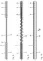
- FIGS. 2 and 3show the micro-catheter tube 1 in the region of a distal tube end 5 .
- the separation strip 4is removed so that an inter-lumen passage opening 6 results, which enables a media passage between the tube lumens 2 and 3 .
- the removal of the separation strip 4 in the area of the distal end of the tube 5can be done by removing material from the distal end side of the micro-catheter tube 1 . This is indicated in FIG. 3 by a circular material removal area 7 covering the separation strip 3 .
- FIG. 4shows the micro-catheter tube 1 again in the region of the distal tube end 5 after performing additional manufacturing steps.
- Fiber material in the form of measuring fibers 8 , 9is introduced into the tube lumens 2 and 3 as a permeable material.
- the distal end of the tube end 5is hermetically sealed by an adhesive sealing plug 10 .
- the latterhas a penetration depth E into the distal end of the tube end 5 , which is so low that the inter-lumen passage opening 6 is not closed by the adhesive sealing plug 10 .
- a removal depth A of the separation strip 4is therefore greater than the penetration depth E.
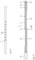
- FIG. 5shows a tube section of the micro-catheter tubes 1 .
- This tube sectioncan be in the region of the distal end of the tube; but this is not mandatory.
- the two tube lumens 2 , 3have in the area of this tube section in each case a window passage opening 11 , 12 , through which a media exchange between the tube lumens 2 , 3 and an environment 13 of the micro-catheter tube 1 is enabled.
- each of the tube lumens 2 , 3has exactly one window passage opening 11 , 12 .
- the micro-catheter tube 1has at least one window passage opening exclusively in one of the two tube lumens 2 or 3 .
- the introduction of the window passage openings 11 , 12can be performed by punching or cutting
- An axial extension AF of the window passage openings 11 , 12i.e. an extension along a longitudinal axis of the tube 14 , is in the range between 2 mm and 30 mm, in particular in the range between 5 mm and 25 mm and can be for example 15 mm.
- FIGS. 6 and 7illustrate various manufacturing steps in the further fabrication of the tubes 1 .
- the measuring fibers 8 and 9are inserted into the tube lumens 2 , 3 each at the height of the window passage openings 11 , 12 .
- Axial extensions AM 1 , AM 2 of the measuring fibers 8 , 9are greater than the axial extension AF of the measurement windows 11 , 12 .
- the axial extensions AM 1 , AM 2can differ from each other; but this is not mandatory.
- the axial extensions AM 1 , AM 2are greater than the axial extension AF, an insert position of the measuring fibers 8 , 9 in the tube lumens 2 , 3 can be guaranteed, in which the measuring fibers 8 , 9 at their end protrude into the opening free lumen areas of tube lumens 2 , 3 , which favors an axial fixation of the measuring fibers 8 , 9 in the tube lumens 2 , 3 in the area of window passage openings 11 , 12 .
- FIG. 7shows the downstream manufacturing step in the further fixing of the measuring fibers 8 , 9 in the tube lumens 2 , 3 by gluing.
- a liquid, curable adhesiveis applied to bonding positions 15 ; the adhesive's viscosity and quantity is matched to a measure of an adhesive gap between an inner tube lumen wall and the measuring fibers 8 , 9 .
- this adhesive gapSeen in a section perpendicular to the longitudinal axis of tube 14 , this adhesive gap has a gap area in the range between 0.01 mm 2 and 0.1 mm 2 , for example, a gap area of 0.04 mm 2 Due to the adjusted viscosity, the adhesive is drawn in by capillary action in the direction of arrows 16 in FIG.
- the quantity of the adhesiveis so adjusted that the adhesive does not penetrate up to the front ends of the measuring fibers 8 , 9 so that an undesired closing of this front-face of the measuring fiber ends by the adhesive is prevented.
- the adhesiveis a targeted curable adhesive substance, for example, an adhesive curable under UV radiation, in particular cyanoacrylate.
- the adhesivemay have a viscosity in the range from 2,500 cP to 4,000 cP (2.5 Pa-s to 4.0 Pa-s) or is in the range between 250 and 400 Pa-s.
- an adhesivecan also be used, in which the curing effect occurs by other influence parameters, for example, by a temperature-controlled curing, a humidity-controlled curing or a purely time-controlled curing.
- an adhesive adjusted in terms of its amount and viscositywhich in particular is adjusted to the inside diameter of the micro-catheter tube 1 in the region of the distal tube end 5 .
- the inner diametercompared to the inter diameter of the tube lumens 2 , 3 , is increased due to the removal of the separation strip 4 , and perpendicular to the separation strip 4 is more than twice as large than the inner diameter of each of the tube lumens 2 , 3 .
- the viscosity of the adhesive for the adhesive sealing plug 10is adjusted so that there results the penetration depth E, which is smaller than the depth A of the removed separation strip 4 .
- the adhesiveis applied to the distal tube end 5 which has an area between 0.1 mm 2 and 0.5 mm 2 and can be, for example, 0.20 mm 2
- the viscosity of the adhesive for the adhesive sealing plug 10lies in the range between 4,000 cP and 8,000 cP (4.0 Pa-s to 8.0 Pa-s) or in the range between 400 and 800 Pa-s.
- a different adhesivethan for the preparation of the adhesive sealing plug 10 .
- FIGS. 8 to 12show further variants of window passage opening that can be used instead of the window openings 11 , 12 .
- the components which correspond to those which have already been explained above in reference to FIGS. 1 to 7have the same reference numerals and will not be discussed again in detail.
- the window passage openings 11 , 12are designed as punched components with sharp, axial-end stages 17 .
- each of the tube lumens 2 , 3has a plurality, namely by way of example shown eight, window passage openings 18 .
- Theseare designed as edge-side punchings in the outer walls of the tube lumens 2 , 3 , wherein the punching movement runs parallel to a separation plane 19 defined by the course of the separation strip 4 (see FIGS. 1 and 9 ), i.e. perpendicular to the drawing plane of FIG. 9 .
- the window passage openings 20are produced by cutting or punching with a cutting motion perpendicular to the parting plane 19 .
- FIG. 12shows a variant of the micro-catheter tubes 1 with two axially staggered window passage openings 21 , 22 which with respect to their axial extension correspond to the window passage openings 11 , 12 according to FIGS. 5 and 8 .
- the axial staggering of the window passage openings 21 , 22 to each otheris so great that the window passage openings 21 , 22 do not axially overlap.
- connection adapter 24is thus attached to the proximal end of the micro-catheter tube 1 .
- this proximal tube endcan be in fluid communication with a supply and discharge device for supplying or discharging a medium.
Landscapes
- Health & Medical Sciences (AREA)
- Life Sciences & Earth Sciences (AREA)
- Biomedical Technology (AREA)
- Pulmonology (AREA)
- Engineering & Computer Science (AREA)
- Anesthesiology (AREA)
- Biophysics (AREA)
- Heart & Thoracic Surgery (AREA)
- Hematology (AREA)
- Animal Behavior & Ethology (AREA)
- General Health & Medical Sciences (AREA)
- Public Health (AREA)
- Veterinary Medicine (AREA)
- Media Introduction/Drainage Providing Device (AREA)
- Measurement Of The Respiration, Hearing Ability, Form, And Blood Characteristics Of Living Organisms (AREA)
Abstract
Description
Claims (21)
Applications Claiming Priority (3)
| Application Number | Priority Date | Filing Date | Title |
|---|---|---|---|
| DE102014226628 | 2014-12-19 | ||
| DE102014226628.9ADE102014226628A1 (en) | 2014-12-19 | 2014-12-19 | Multi-lumen microcatheter tube and method of making a multi-lumen microcatheter tube |
| DE102014226628.9 | 2014-12-19 |
Publications (2)
| Publication Number | Publication Date |
|---|---|
| US20160175558A1 US20160175558A1 (en) | 2016-06-23 |
| US10758707B2true US10758707B2 (en) | 2020-09-01 |
Family
ID=55022286
Family Applications (1)
| Application Number | Title | Priority Date | Filing Date |
|---|---|---|---|
| US14/972,370Active2037-09-08US10758707B2 (en) | 2014-12-19 | 2015-12-17 | Multiple lumen microcatheter tube and method for manufacturing multiple lumen microcatheter tubes |
Country Status (4)
| Country | Link |
|---|---|
| US (1) | US10758707B2 (en) |
| EP (1) | EP3033998B1 (en) |
| DE (1) | DE102014226628A1 (en) |
| DK (1) | DK3033998T3 (en) |
Citations (38)
| Publication number | Priority date | Publication date | Assignee | Title |
|---|---|---|---|---|
| US4274417A (en)* | 1978-09-22 | 1981-06-23 | National Research Development Corporation | Instruments for use in the measurement of gases in body fluids |
| GB2130916B (en)* | 1982-12-01 | 1986-07-09 | Carl Urban Ungerstedt | Dialysis probe |
| US5191900A (en)* | 1991-04-10 | 1993-03-09 | The Board Of Trustees Of The University Of Illinois | Dialysis probe |
| US5195962A (en)* | 1987-12-22 | 1993-03-23 | Vas-Cath Incorporated | Triple lumen catheter |
| US5364344A (en)* | 1993-10-22 | 1994-11-15 | The Kendall Company | Dual lumen catheter |
| US5607390A (en) | 1992-12-15 | 1997-03-04 | Institute Of Neurology | Dialysis probe |
| US5718678A (en)* | 1996-06-26 | 1998-02-17 | Medical Components, Inc. | Multi-lumen coaxial catheter and method for making same |
| DE19714572C1 (en) | 1997-04-09 | 1998-06-25 | Haindl Hans | Catheter for measuring chemical parameters in biological tissue |
| US5800414A (en)* | 1996-10-18 | 1998-09-01 | Synthelabo | Catheter with flexible and elongate body |
| WO2001003752A1 (en) | 1999-07-14 | 2001-01-18 | Cma/Microdialysis Ab | Microdialysis probe |
| US6245187B1 (en)* | 1996-06-05 | 2001-06-12 | Siemens Aktiengesellschaft | Mechanically firm glued connections between surfaces and the method for producing the same |
| US6254628B1 (en)* | 1996-12-09 | 2001-07-03 | Micro Therapeutics, Inc. | Intracranial stent |
| US6264627B1 (en)* | 1998-03-11 | 2001-07-24 | Jan Liska | Catheter to be inserted into a blood vessel, and a method for detection of substances and metabolic changes in a heart |
| WO2004060465A2 (en) | 2002-12-23 | 2004-07-22 | Boston Scientific Limited | Methods and apparatuses for performing procedures in the subarachnoid space |
| US6772761B1 (en)* | 2002-08-19 | 2004-08-10 | Joseph W. Rucker, Jr. | Gas delivery tube |
| US20040193098A1 (en)* | 2001-10-05 | 2004-09-30 | Angela Wentling | Continuous flow peritoneal dialysis catheter |
| US20050119597A1 (en)* | 2003-12-02 | 2005-06-02 | Chf Solutions, Inc. | Method and apparatus for ultrafiltration utilizing a peripheral access dual lumen venous cannula |
| US20050137579A1 (en)* | 2003-12-23 | 2005-06-23 | Medtronic, Inc. | Permeable membrane catheters, systems, and methods |
| US20050261663A1 (en)* | 2004-03-03 | 2005-11-24 | Patterson Ryan C | Loop-tip catheter |
| US20060142703A1 (en)* | 2004-12-07 | 2006-06-29 | Cook Incorporated | Catheter aperture with related structures and method |
| US20060173440A1 (en)* | 2001-01-17 | 2006-08-03 | Medtronic Vascular, Inc. | Microcatheter Devices and Methods for Targeted Substance Delivery |
| US20070255230A1 (en)* | 2006-04-27 | 2007-11-01 | Sdgi Holdings, Inc. | Vented directional delivery cannula with openings of different size for use with flowable materials and method for use thereof |
| US20080082080A1 (en)* | 2006-09-29 | 2008-04-03 | Tyco Healthcare Group Lp | Acute hemodialysis catheter assembly |
| US20090118661A1 (en)* | 2007-11-01 | 2009-05-07 | C. R. Bard, Inc. | Catheter assembly including triple lumen tip |
| US20090192435A1 (en)* | 2007-10-26 | 2009-07-30 | C. R. Bard, Inc. | Solid-body catheter including lateral distal openings |
| US20090198219A1 (en)* | 2003-01-17 | 2009-08-06 | Campbell Carey V | Catheter Assembly |
| WO2009095020A1 (en) | 2008-01-30 | 2009-08-06 | Diramo A/S | A micro-dialysis probe and a method of making the probe |
| US20090209940A1 (en)* | 2008-02-15 | 2009-08-20 | Spire Corporation | Fusion manufacture of multi-lumen catheters |
| US20090216151A1 (en)* | 2008-02-27 | 2009-08-27 | Speeg Trevor W V | Biopsy Probe With Hypodermic Lumen |
| US20100324503A1 (en)* | 2008-04-22 | 2010-12-23 | Becton, Dickinson And Company | Catheter hole having a flow breaking feature |
| US20110130745A1 (en)* | 2008-04-22 | 2011-06-02 | Becton, Dickinson And Company | Catheter hole having an inclined trailing edge |
| US20110270368A1 (en)* | 1998-08-24 | 2011-11-03 | Zoll Circulation Inc. | Heat Exchange Catheter System |
| US8066660B2 (en)* | 2007-10-26 | 2011-11-29 | C. R. Bard, Inc. | Split-tip catheter including lateral distal openings |
| US20120041419A1 (en)* | 2010-08-12 | 2012-02-16 | C. R. Bard, Inc. | Trimmable catheter including distal portion stability features |
| US20120172791A1 (en)* | 2002-03-22 | 2012-07-05 | Twin Star Medical, Inc. | Method and system for treating tissue swelling |
| US8333740B2 (en)* | 2009-05-01 | 2012-12-18 | Shippert Ronald D | Tissue transfer cannula |
| WO2014149708A1 (en) | 2013-03-15 | 2014-09-25 | Cook Medical Technologies Llc | Pressure sensing catheter |
| US20170348512A1 (en)* | 2015-07-20 | 2017-12-07 | Strataca Systems, LLC | Ureteral and Bladder Catheters and Methods of Inducing Negative Pressure to Increase Renal Perfusion |
Family Cites Families (2)
| Publication number | Priority date | Publication date | Assignee | Title |
|---|---|---|---|---|
| US3893448A (en)* | 1973-11-26 | 1975-07-08 | John W Brantigan | Catheter device for use in detecting gas in body fluids and tissue |
| EP2027812A1 (en)* | 2007-08-24 | 2009-02-25 | F. Hoffman-la Roche AG | Method for manufacturing a micro-dialysis catheter and micro-dialysis catheter manufactured accordingly |
- 2014
- 2014-12-19DEDE102014226628.9Apatent/DE102014226628A1/enactivePending
- 2015
- 2015-12-15DKDK15200215.0Tpatent/DK3033998T3/enactive
- 2015-12-15EPEP15200215.0Apatent/EP3033998B1/enactiveActive
- 2015-12-17USUS14/972,370patent/US10758707B2/enactiveActive
Patent Citations (41)
| Publication number | Priority date | Publication date | Assignee | Title |
|---|---|---|---|---|
| US4274417A (en)* | 1978-09-22 | 1981-06-23 | National Research Development Corporation | Instruments for use in the measurement of gases in body fluids |
| GB2130916B (en)* | 1982-12-01 | 1986-07-09 | Carl Urban Ungerstedt | Dialysis probe |
| US5195962A (en)* | 1987-12-22 | 1993-03-23 | Vas-Cath Incorporated | Triple lumen catheter |
| US5191900A (en)* | 1991-04-10 | 1993-03-09 | The Board Of Trustees Of The University Of Illinois | Dialysis probe |
| DE69323563T2 (en) | 1992-12-15 | 1999-09-16 | Institute Of Neurology, London | PROBE FOR DIALYSIS |
| US5607390A (en) | 1992-12-15 | 1997-03-04 | Institute Of Neurology | Dialysis probe |
| US5364344A (en)* | 1993-10-22 | 1994-11-15 | The Kendall Company | Dual lumen catheter |
| US6245187B1 (en)* | 1996-06-05 | 2001-06-12 | Siemens Aktiengesellschaft | Mechanically firm glued connections between surfaces and the method for producing the same |
| US5718678A (en)* | 1996-06-26 | 1998-02-17 | Medical Components, Inc. | Multi-lumen coaxial catheter and method for making same |
| US5800414A (en)* | 1996-10-18 | 1998-09-01 | Synthelabo | Catheter with flexible and elongate body |
| US6254628B1 (en)* | 1996-12-09 | 2001-07-03 | Micro Therapeutics, Inc. | Intracranial stent |
| US6669719B2 (en)* | 1996-12-09 | 2003-12-30 | Microtherapeutics, Inc. | Intracranial stent and method of use |
| DE19714572C1 (en) | 1997-04-09 | 1998-06-25 | Haindl Hans | Catheter for measuring chemical parameters in biological tissue |
| US6264627B1 (en)* | 1998-03-11 | 2001-07-24 | Jan Liska | Catheter to be inserted into a blood vessel, and a method for detection of substances and metabolic changes in a heart |
| US20110270368A1 (en)* | 1998-08-24 | 2011-11-03 | Zoll Circulation Inc. | Heat Exchange Catheter System |
| US6929618B1 (en)* | 1999-07-14 | 2005-08-16 | Cma/Microdialysis Ab | Microdialysis probe |
| WO2001003752A1 (en) | 1999-07-14 | 2001-01-18 | Cma/Microdialysis Ab | Microdialysis probe |
| US20060173440A1 (en)* | 2001-01-17 | 2006-08-03 | Medtronic Vascular, Inc. | Microcatheter Devices and Methods for Targeted Substance Delivery |
| US20040193098A1 (en)* | 2001-10-05 | 2004-09-30 | Angela Wentling | Continuous flow peritoneal dialysis catheter |
| US20120172791A1 (en)* | 2002-03-22 | 2012-07-05 | Twin Star Medical, Inc. | Method and system for treating tissue swelling |
| US6772761B1 (en)* | 2002-08-19 | 2004-08-10 | Joseph W. Rucker, Jr. | Gas delivery tube |
| WO2004060465A2 (en) | 2002-12-23 | 2004-07-22 | Boston Scientific Limited | Methods and apparatuses for performing procedures in the subarachnoid space |
| US20090198219A1 (en)* | 2003-01-17 | 2009-08-06 | Campbell Carey V | Catheter Assembly |
| US20050119597A1 (en)* | 2003-12-02 | 2005-06-02 | Chf Solutions, Inc. | Method and apparatus for ultrafiltration utilizing a peripheral access dual lumen venous cannula |
| US20050137579A1 (en)* | 2003-12-23 | 2005-06-23 | Medtronic, Inc. | Permeable membrane catheters, systems, and methods |
| US20050261663A1 (en)* | 2004-03-03 | 2005-11-24 | Patterson Ryan C | Loop-tip catheter |
| US20060142703A1 (en)* | 2004-12-07 | 2006-06-29 | Cook Incorporated | Catheter aperture with related structures and method |
| US20070255230A1 (en)* | 2006-04-27 | 2007-11-01 | Sdgi Holdings, Inc. | Vented directional delivery cannula with openings of different size for use with flowable materials and method for use thereof |
| US20080082080A1 (en)* | 2006-09-29 | 2008-04-03 | Tyco Healthcare Group Lp | Acute hemodialysis catheter assembly |
| US8066660B2 (en)* | 2007-10-26 | 2011-11-29 | C. R. Bard, Inc. | Split-tip catheter including lateral distal openings |
| US20090192435A1 (en)* | 2007-10-26 | 2009-07-30 | C. R. Bard, Inc. | Solid-body catheter including lateral distal openings |
| US20090118661A1 (en)* | 2007-11-01 | 2009-05-07 | C. R. Bard, Inc. | Catheter assembly including triple lumen tip |
| WO2009095020A1 (en) | 2008-01-30 | 2009-08-06 | Diramo A/S | A micro-dialysis probe and a method of making the probe |
| US20090209940A1 (en)* | 2008-02-15 | 2009-08-20 | Spire Corporation | Fusion manufacture of multi-lumen catheters |
| US20090216151A1 (en)* | 2008-02-27 | 2009-08-27 | Speeg Trevor W V | Biopsy Probe With Hypodermic Lumen |
| US20100324503A1 (en)* | 2008-04-22 | 2010-12-23 | Becton, Dickinson And Company | Catheter hole having a flow breaking feature |
| US20110130745A1 (en)* | 2008-04-22 | 2011-06-02 | Becton, Dickinson And Company | Catheter hole having an inclined trailing edge |
| US8333740B2 (en)* | 2009-05-01 | 2012-12-18 | Shippert Ronald D | Tissue transfer cannula |
| US20120041419A1 (en)* | 2010-08-12 | 2012-02-16 | C. R. Bard, Inc. | Trimmable catheter including distal portion stability features |
| WO2014149708A1 (en) | 2013-03-15 | 2014-09-25 | Cook Medical Technologies Llc | Pressure sensing catheter |
| US20170348512A1 (en)* | 2015-07-20 | 2017-12-07 | Strataca Systems, LLC | Ureteral and Bladder Catheters and Methods of Inducing Negative Pressure to Increase Renal Perfusion |
Also Published As
| Publication number | Publication date |
|---|---|
| EP3033998A1 (en) | 2016-06-22 |
| DE102014226628A1 (en) | 2016-06-23 |
| US20160175558A1 (en) | 2016-06-23 |
| EP3033998B1 (en) | 2020-02-12 |
| DK3033998T3 (en) | 2020-05-11 |
Similar Documents
| Publication | Publication Date | Title |
|---|---|---|
| US20200305930A1 (en) | Bone Marrow Access Device | |
| CN102791209B (en) | Puncture needle for bone cement injection | |
| US8002763B2 (en) | Catheter flushing mandrel | |
| JP6518797B2 (en) | Flexible biopsy needle | |
| JP2017035520A (en) | Overmolded medical connector tubing and method | |
| KR102431658B1 (en) | System for navigation and visualization of body passages | |
| CN104771803A (en) | Catheter aseembly blood control device and related methods | |
| CN105492063A (en) | Delivery catheter apparatus and methods | |
| WO2007041450A3 (en) | Needle-based medical device including needle guide and method for constructing | |
| US10434265B2 (en) | Medical hollow needle assembly and method of manufacturing hollow needle | |
| US10188845B2 (en) | Hemostasis valve assembly | |
| CN102753219A (en) | Method for producing a component having a cannula, cannula, component having a cannula and insertion head | |
| US9572955B2 (en) | Catheter-to-extension tube assembly and method of making same | |
| CN108310622B (en) | Needle set | |
| US20040116830A1 (en) | Blood testing deivce | |
| US10758707B2 (en) | Multiple lumen microcatheter tube and method for manufacturing multiple lumen microcatheter tubes | |
| US6616625B2 (en) | Catheter for measuring chemical parameters, in particular for introducing biological tissues, liquids or the like | |
| EP3800353B1 (en) | Joint structure, joint unit and assembly method of joint unit | |
| CN110167627B (en) | Groove seal | |
| US11376396B2 (en) | Catheter assembly | |
| JP6787626B2 (en) | Needle assembly with flashback chamber for collecting blood or other liquid samples | |
| EP3142724B1 (en) | Medical technology measuring device and measurement method | |
| WO2013025862A1 (en) | Device and method for use in the collection of whole saliva in research and diagnostics | |
| US8911405B2 (en) | Needle device | |
| CN205339000U (en) | A sampling needle and sampling needle subassembly for puncture |
Legal Events
| Date | Code | Title | Description |
|---|---|---|---|
| AS | Assignment | Owner name:RAUMEDIC AG, GERMANY Free format text:ASSIGNMENT OF ASSIGNORS INTEREST;ASSIGNOR:GLAESEL, BJOERN;REEL/FRAME:038281/0184 Effective date:20160120 | |
| STPP | Information on status: patent application and granting procedure in general | Free format text:FINAL REJECTION MAILED | |
| STPP | Information on status: patent application and granting procedure in general | Free format text:DOCKETED NEW CASE - READY FOR EXAMINATION | |
| STPP | Information on status: patent application and granting procedure in general | Free format text:NON FINAL ACTION MAILED | |
| STPP | Information on status: patent application and granting procedure in general | Free format text:NOTICE OF ALLOWANCE MAILED -- APPLICATION RECEIVED IN OFFICE OF PUBLICATIONS | |
| STPP | Information on status: patent application and granting procedure in general | Free format text:PUBLICATIONS -- ISSUE FEE PAYMENT RECEIVED | |
| STCF | Information on status: patent grant | Free format text:PATENTED CASE | |
| FEPP | Fee payment procedure | Free format text:SURCHARGE FOR LATE PAYMENT, LARGE ENTITY (ORIGINAL EVENT CODE: M1554); ENTITY STATUS OF PATENT OWNER: LARGE ENTITY | |
| MAFP | Maintenance fee payment | Free format text:PAYMENT OF MAINTENANCE FEE, 4TH YEAR, LARGE ENTITY (ORIGINAL EVENT CODE: M1551); ENTITY STATUS OF PATENT OWNER: LARGE ENTITY Year of fee payment:4 |