US10758399B2 - Device, system, kit or method for collecting effluent from an individual - Google Patents
Device, system, kit or method for collecting effluent from an individualDownload PDFInfo
- Publication number
- US10758399B2 US10758399B2US14/273,066US201414273066AUS10758399B2US 10758399 B2US10758399 B2US 10758399B2US 201414273066 AUS201414273066 AUS 201414273066AUS 10758399 B2US10758399 B2US 10758399B2
- Authority
- US
- United States
- Prior art keywords
- reservoir
- insertable member
- effluent
- insertable
- conduit
- Prior art date
- Legal status (The legal status is an assumption and is not a legal conclusion. Google has not performed a legal analysis and makes no representation as to the accuracy of the status listed.)
- Expired - Fee Related, expires
Links
Images


Classifications
- A—HUMAN NECESSITIES
- A61—MEDICAL OR VETERINARY SCIENCE; HYGIENE
- A61M—DEVICES FOR INTRODUCING MEDIA INTO, OR ONTO, THE BODY; DEVICES FOR TRANSDUCING BODY MEDIA OR FOR TAKING MEDIA FROM THE BODY; DEVICES FOR PRODUCING OR ENDING SLEEP OR STUPOR
- A61M1/00—Suction or pumping devices for medical purposes; Devices for carrying-off, for treatment of, or for carrying-over, body-liquids; Drainage systems
- A61M1/71—Suction drainage systems
- A61M1/77—Suction-irrigation systems
- A—HUMAN NECESSITIES
- A61—MEDICAL OR VETERINARY SCIENCE; HYGIENE
- A61F—FILTERS IMPLANTABLE INTO BLOOD VESSELS; PROSTHESES; DEVICES PROVIDING PATENCY TO, OR PREVENTING COLLAPSING OF, TUBULAR STRUCTURES OF THE BODY, e.g. STENTS; ORTHOPAEDIC, NURSING OR CONTRACEPTIVE DEVICES; FOMENTATION; TREATMENT OR PROTECTION OF EYES OR EARS; BANDAGES, DRESSINGS OR ABSORBENT PADS; FIRST-AID KITS
- A61F5/00—Orthopaedic methods or devices for non-surgical treatment of bones or joints; Nursing devices ; Anti-rape devices
- A61F5/44—Devices worn by the patient for reception of urine, faeces, catamenial or other discharge; Colostomy devices
- A61F5/451—Genital or anal receptacles
- A61M1/0023—
- A61M1/0052—
- A61M1/008—
- A—HUMAN NECESSITIES
- A61—MEDICAL OR VETERINARY SCIENCE; HYGIENE
- A61M—DEVICES FOR INTRODUCING MEDIA INTO, OR ONTO, THE BODY; DEVICES FOR TRANSDUCING BODY MEDIA OR FOR TAKING MEDIA FROM THE BODY; DEVICES FOR PRODUCING OR ENDING SLEEP OR STUPOR
- A61M1/00—Suction or pumping devices for medical purposes; Devices for carrying-off, for treatment of, or for carrying-over, body-liquids; Drainage systems
- A61M1/71—Suction drainage systems
- A61M1/78—Means for preventing overflow or contamination of the pumping systems
- A61M1/784—Means for preventing overflow or contamination of the pumping systems by filtering, sterilising or disinfecting the exhaust air, e.g. swellable filter valves
- A—HUMAN NECESSITIES
- A61—MEDICAL OR VETERINARY SCIENCE; HYGIENE
- A61M—DEVICES FOR INTRODUCING MEDIA INTO, OR ONTO, THE BODY; DEVICES FOR TRANSDUCING BODY MEDIA OR FOR TAKING MEDIA FROM THE BODY; DEVICES FOR PRODUCING OR ENDING SLEEP OR STUPOR
- A61M1/00—Suction or pumping devices for medical purposes; Devices for carrying-off, for treatment of, or for carrying-over, body-liquids; Drainage systems
- A61M1/84—Drainage tubes; Aspiration tips
- A61M1/85—Drainage tubes; Aspiration tips with gas or fluid supply means, e.g. for supplying rinsing fluids or anticoagulants
- A—HUMAN NECESSITIES
- A61—MEDICAL OR VETERINARY SCIENCE; HYGIENE
- A61M—DEVICES FOR INTRODUCING MEDIA INTO, OR ONTO, THE BODY; DEVICES FOR TRANSDUCING BODY MEDIA OR FOR TAKING MEDIA FROM THE BODY; DEVICES FOR PRODUCING OR ENDING SLEEP OR STUPOR
- A61M13/00—Insufflators for therapeutic or disinfectant purposes, i.e. devices for blowing a gas, powder or vapour into the body
- A61M13/003—Blowing gases other than for carrying powders, e.g. for inflating, dilating or rinsing
- A61M1/0084—
- A—HUMAN NECESSITIES
- A61—MEDICAL OR VETERINARY SCIENCE; HYGIENE
- A61M—DEVICES FOR INTRODUCING MEDIA INTO, OR ONTO, THE BODY; DEVICES FOR TRANSDUCING BODY MEDIA OR FOR TAKING MEDIA FROM THE BODY; DEVICES FOR PRODUCING OR ENDING SLEEP OR STUPOR
- A61M2209/00—Ancillary equipment
- A61M2209/08—Supports for equipment
- A61M2209/084—Supporting bases, stands for equipment
- A—HUMAN NECESSITIES
- A61—MEDICAL OR VETERINARY SCIENCE; HYGIENE
- A61M—DEVICES FOR INTRODUCING MEDIA INTO, OR ONTO, THE BODY; DEVICES FOR TRANSDUCING BODY MEDIA OR FOR TAKING MEDIA FROM THE BODY; DEVICES FOR PRODUCING OR ENDING SLEEP OR STUPOR
- A61M2210/00—Anatomical parts of the body
- A61M2210/10—Trunk
- A61M2210/1042—Alimentary tract
- A61M2210/1067—Anus
Definitions
- the present inventionrelates to a device, method, system and kit for collecting effluent from an individual during or after a medical or diagnostic procedure.
- the term “effluent”includes, but is not limited to, any solid, semi-solid, liquid, or gaseous matter from the inside of an individual's body.
- the present inventionprovides a means by which a desired medium can pass to and from a body cavity of an individual undergoing a medical or diagnostic procedure, and, at the same time, prevent the individual's effluent from coming into contact with the equipment used to perform the medical or diagnostic procedure.
- the term “medium”,includes, but is not limited to, any solid, semi-solid, liquid or gaseous matter administered to an individual in order to perform a useful medical or diagnostic procedure.
- the diagnostic performance of gastrointestinal imagingis facilitated by distending a desired body part prior to and during the diagnostic procedure.
- distentionis maintained throughout the procedure to obtain the most accurate image.
- insufflatorto the proximal end of a rectal catheter inserted into the rectum of the individual.
- CO 2air or CO 2 , for example, is introduced into the colon.
- insufflation equipmentis used with multiple individuals. In this regard, it is essential that the equipment not be contaminated from use by any other patient. Frequently, effluent, such as stool, is expelled from the patient during the insufflation procedure, and often contacts and thus contaminates the insufflation equipment.
- the present inventionprovides an effluent collection reservoir interfaced with a conduit used to administer a medium into an individual's body cavity during or after a medical or diagnostic procedure.
- a conduitused to administer a medium into an individual's body cavity during or after a medical or diagnostic procedure.
- any effluent expelled at the onset of a proceduremigrates and collects in this reservoir, thereby preventing the effluent from impeding the administration of the medium.
- the desired mediumis free to migrate through the conduit and into the individual's cavity.
- the present inventionis suitable for use with insufflation devices because it provides an efficient, disposable device by which a medium can pass to the patient while maintaining the sterility of the insufflator, such that it can be used with multiple individuals.
- distention gasis free to flow bi-directionally, thereby allowing one to utilize the pressure-sensing capability of an electro-pneumatic insufflator, for example, which is used to distend a cavity (e.g., colon) automatically by a constant, user set pressure.
- a barrieris positioned in front of the connection site between the present invention and the equipment used to perform the medical or diagnostic procedure.
- effluent escaping from the reservoircannot contact the equipment during the procedure.
- barriers positioned in front of each opening to the effluent reservoirthe expelled stool/effluent can be easily contained to minimize mess and ease disposal of the effluent at the end of a procedure.
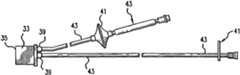
- FIG. 1shows an alternative embodiment of the present invention, without an insertable member.
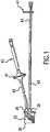
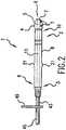
- FIGS. 2-5are perspective views of alternative effluent collection reservoirs of the present invention.
- FIG. 6is a side view of an alternative effluent barrier of the present invention.
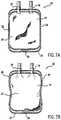
- FIGS. 7A, 7B, and 8are perspective views of alternative means for preventing the passage of effluent or medium from one location to another.
- FIG. 9is a perspective view of an alternative insertable member of the present invention.
- FIG. 10is a perspective view of an alternative insertable member of the present invention, with enlarged expandable member.
- FIG. 11is a front and side view of an alternative insertable member showing the expandable portion in non-enlarged and enlarged positions.
- FIGS. 12 and 13are perspective views of an alternative insertable member of the present invention.
- FIG. 14shows alternative embodiment of the present invention, with insertable member connected thereto.
- FIG. 15shows an alternative embodiment of the present invention used in connection with an insufflator unit.
- FIG. 16shows an alternative embodiment of the present invention including sensors.
- FIG. 17shows an alternative embodiment of the present invention including a porous filter media.
- the device, system, kit or method of the present inventioncomprises an effluent reservoir. More specifically, the present invention comprises an effluent reservoir adapted for use in connection with performing a medical or diagnostic procedure of an anatomical area of interest. Such procedures may also include, but are not limited to, gastrointestinal imaging, including, but not limited to, X-ray imaging or virtual gastrointestinal imaging, for example. Virtual gastrointestinal imaging includes any technique of using computer software to view the inside of any section of the gastrointestinal tract, including CT imaging, MR imaging, PET imaging, PET imaging, or the like. Such medical or diagnostic procedures may also include fiberoptic endoscopy, optical colonoscopy, sigmoidoscopy and the like.
- the effluent collection devicecomprising one or more means of interfacing with the device(s) used in the medical or diagnostic procedure, including, but not limited to an instrument for examining the interior of a body cavity, such as an endoscope, for example.
- Such device(s)may also include an insufflator or any other instrument for administering a powder, gas, liquid or vapor into a body cavity.
- Such device(s)may further include an aspirator or any other instrument that is used to create a partial or complete vacuum in a body cavity, or an instrument that removes liquids, solids or gases from a space by suction, particularly instruments used medicinally to evacuate a body cavity during or after a medical or diagnostic procedure.
- the effluent reservoirinterfaces with a medical or diagnostic device such that a medically and/or diagnostically useful procedure can be performed involving an individual's body cavity, and at the same time, prevent effluent passing through an opening of said cavity from impeding or otherwise adversely affecting the procedure or the outcome of the procedure.
- the effluent reservoirmay also interface with the medical or diagnostic device(s) such that the effluent does not contact, and thus contaminate said device(s) during or after the medical or diagnostic procedure.
- the effluent reservoirmay comprise a hollow interior capable of receiving and collecting effluent that passes through an opening of an individual's internal cavity during or after a diagnostic or medical procedure, for example.
- the effluent reservoiris particularly useful as a reservoir for collecting effluent from an individual's body cavity, thus preventing it from reentering the body cavity or contaminating a component, device or apparatus used in connection with a medical or diagnostic procedure.
- the effluent reservoircomprises an interior area having a closed bottom, and front and rear walls secured together around their periphery.
- the reservoirmay also comprise one or more ports or openings for admitting or removing effluent to the interior of the effluent reservoir.
- the reservoirmay further include one or more ports or opening for use in conveying a desired medium through the interior of the effluent reservoir.
- the reservoirmay hold about 10 cc to 500 cc of fluid, preferably about 10 cc to 100 cc, more preferably about 60 cc to 100 cc.
- the effluent reservoirmay hold approximately 60 cc or 100 cc of fluid, respectively.
- the effluent reservoir of the present inventionhas a bag-like shape. Alternatively, it may have a bottle-like, tray-like, box-like, or tube-like shape, for example. In another embodiment, the effluent reservoir may comprise a rigid container or jar, or it make take the form of a collapsible container.
- a collapsible containeris its smaller material volume which facilitates handling during manufacture, storage, shipping, use and disposal.
- connection meansincludes, but is not limited to means for forming a connection with one or more other components.
- connection meansincludes, but is not limited to, means for forming a Luer connection, Colder connection, barbed connection, male/female type connection or any equivalent thereof.
- connection meansprovides means for forming a fluid-type seal between at least one effluent opening and one or more conduits, insertable members or apparatuses used in connection with a medical or diagnostic procedure.
- the effluent reservoir of the present inventionmay be prepared from suitable plastic material whereby a strong, lightweight, reliable, yet economic container is provided.
- the effluent reservoir of the present inventionmay be constructed of any suitable elastomeric material, such as olefin-based materials, including but not limited to, polyethylene, ethylene-propylene copolymers, ethylene-vinyl acetate copolymers, ethylene-acrylic ester copolymers, iononomers, and combinations thereof.
- film layers of polymers having gas barrier propertysuch as polyvinylidene chloride and ethylene-vinyl alcohol copolymers, as well as film layers of such polymers as polyvinyl chloride, polyester, polyamide and polyurethanes may also be used.
- the effluent reservoirsmay also comprise any flexible material, including polyethylene film, plasticized polyvinyl chloride film, plasticized polyvinylidene chloride film polyethylene/ethylene-vinyl acetate copolymer laminate, ethylene-vinyl acetate copolymer/polyvinylidene chloride/ethylene-vinyl acetate copolymer laminate, and polyethylene/ethylene-vinyl acetate copolymer/polyethylene chloride/ethylene-vinyl acetate copolymer/polyethylene laminate, among others.
- the effluent reservoirmay comprise materials that make it suitable for disposal in a flush toilet. Such materials comprising a biodegradable polymer, for example.
- the effluent reservoirmay be interfaced with one or more apparatus used to perform a medical or diagnostic procedure. Such interface may be achieved through one or more conduits positioned between the effluent reservoir and apparatus, for example.
- a conduitmay include any hollow area capable of conveying any medium or effluent from one location to another.
- the conduitmay include a structure that comprises one or more hollow areas, and is capable of conveying a medium or effluent or otherwise functions as a passageway for those materials.
- the conduitmay include, but is not limited to, a hollow cylinder such as a tube, channel, or pipe.
- the conduitmay also comprise a single lumen or multilumens.
- connection meansincludes, but is not limited to, means for forming a connection with one or more components.
- connection meansincludes a Luer connection, Colder connection, barbed connection, male/female connection or any equivalent thereof.
- connection meansprovides means for forming a fluid-type seal between one or more portions of the conduit and an insertable member, opening of the effluent reservoir or one or more apparatuses used in the medical or diagnostic procedure.
- the conduit of the present inventionmay be constituted of any suitable elastomeric material, such as olefin-based materials, including but not limited to, polyethylene, ethylene, ethylene-propylene copolymers, ethylene-vinyl acetate copolymers, ethylene-acrylic ester copolymers, lonomers, and combinations thereof.
- the conduitsmay be constructed of ployviylders chloride or ethylene-vinyl alcohol copolymers, as well as polyvinyl chloride, polyester, polyamide or polyurethanes, silicone, rubber, nylon, PTFE.
- the present inventionmay also comprise one or more bathers to prevent effluent or medium from migrating from one location to another.
- the one or more barriersmay be positioned at one or more sites including, but not limited to, any location between the effluent reservoir and the area to be protected from contact with the individual's effluent.
- one or more bathersmay be so positioned in order to prevent effluent from contacting, and thus contaminating a component, device or apparatus used in connection with a medical or diagnostic procedure.
- the barriersmay be so positioned in various locations in order to prevent the medium or expelled effluent from migrating through the cavity opening and into the individual's internal cavity.
- the barriermay comprise one or more layers of material impervious to the passage of water, but not gas. Such a barrier may materially reduce the transfer of pathogens, such as viruses and bacteria, mucous and fluid.
- the effluent barriermay comprise a hydrophobic membrane to provide an anti-viral and anti-bacterial barrier, including but not limited to a 0.1 micron hydrophobic membrane.
- the effluent barriermay also comprise any other well known, commercially available filtration media system impervious to biological matter.
- the filtration media's performancemay be enhanced by placing an in-line check valve or unidirectional valve on a side of the filtration media.
- the effluent barrierneed not be an independent, stand-alone structure. It can form an integral part of any component of the present invention.
- an appropriate hydrophobic membranemay form an integral part of the one or more openings of the effluent reservoir.
- the barriermay also form an integral part of the interior of the conduit or insertable member.
- the present inventionmay have an adjustable barrier for limiting or preventing the effluent or medium from migrating from one location to another during or after the medical or diagnostic procedure.
- the adjustable barriermay include but is not limited to, a clamp, valve, stop-cock, slide clamp or pinch clamp.
- the insertable membermay support a locking pinch clamp.
- the insertable memberis suitable for insertion into an opening of a cavity of an individual.
- the insertable membermay have one or more hollow areas, such as a multilumen tube, for example.
- the body cavities of the individualmay include, but are not limited to, the mouth, vagina, urethra, ear, nostril, uterus, appendix, cecum, hepatitic flexure, transverse colon, descending colon, sigmoid, rectum or any other body orifice, channel or opening to an individual's body, including incisions into the individual's body.
- the insertable membermay include, but is not limited to, an instrument for examining the interior of the individual's cavity, such as a trocar, endoscope, enema tip, Foley catheter, entry needle, for example. It may also include an instrument for administering a powder, gas, liquid or vapor into a body cavity, such as an automatic or manual insufflator. The insertable member may further include an instrument for removing liquid, gas or solid from the interior of an individual's cavity.
- connection meansincluding, but is not limited to, means for forming a connection with one or more other components.
- connection meansincludes, but is not limited to, means for forming a Luer connection, Colder connection, barbed connection, male/female type connection or any equivalent thereof.
- connection meansprovides means for forming a fluid-type seal between a hollow area of an insertable member with one or more conduits or openings of the effluent reservoir.
- the front portioncomprising a tip structure supported thereon.
- the tip structureis adapted to initiate entry of the insertable member into an opening to an individual's body cavity.
- the insertable membermay be structured so that part or at least substantially all of said member is inserted through the opening of the individual's cavity.
- the insertable membermay have a hollow portion positioned internally. The hollow portion extending from the front end of the insertable member to its rear end.
- the insertable memberis capable of maintaining an opening to the cavity.
- the tipmay be lubricated and gently passed into the cavity. The tip can be removed from the cavity at any time by gentle traction therefrom.
- the configuration of the tip structuremay comprise various shapes and forms.
- the tip structuremay be cylindrical or non-cylindrical.
- the circumference of the tip structuremay be substantially equal to or greater than other portions of the insertable member.
- the tip structuremay also comprise an apex.
- the shape or form of one or more sections of the tip structuremay include, but is not limited to, annular, planar, circular, rounded concave, convex, conical, elliptical, ellipsoidal, conidial, crescent-like, helical, oblong, oval, parabolic, round, sinusoidal, spherical, hemi-spherical, tapered, tubular, triangular, wedge-like, head-like or any other configuration capable of insertion into the opening of an individual's body cavity.
- the insertable membermay comprise a shaft having a distal end and proximal end.
- the tip structuremay be positioned adjacent to the proximal end of the shaft.
- the distal endmay be interfaced with the effluent reservoir.
- the interior of the shaftmay comprise one or more hollow areas extending along part of or at least substantially the entire length of the shaft.
- the hollow area of the shaftcan be completely or partially aligned with a hollow area of the tip structure of the insertable member, thus forming a conduit extending from the front portion of the insertable member to its rear portion.
- the tip and shaftmay represent separate identifiable components or they may represent one single component of the insertable member.
- the insertable membermay comprise a solid, substantially rigid material. Such materials may also include PVC or Polyethylene, for example. It may also comprise a substantially resilient material, such as rubber or an elastomeric polymer, such as a soft plastic, polyurethane, latex, nylon, PTFE, silicone or a blend thereof.
- a substantially resilient materialsuch as rubber or an elastomeric polymer, such as a soft plastic, polyurethane, latex, nylon, PTFE, silicone or a blend thereof.
- Restraining Meanse.g., Inflatable Cuff
- the present inventionmay also comprise one or more restraining means to maintain the insertable member in a desired position once inserted through the opening of the individual's body cavity.
- the restraining meansmay prevent the tip of the insertable member from being displaced after insertion into the individual's body cavity. Further, the restraining means may prevent further penetration and/or maintain an appropriate seal between the insertable member and the outer periphery of the cavity once said member passes through the opening of the cavity.
- the restraining meansmay be selectively adjustable so that the insertion depth of the insertable member or its rotational orientation can be varied to fit different size anatomies.
- the restraining meansmay comprise an expandable member adapted to facilitate placement of the insertable member in the individual's cavity.
- the expandable membermay be positioned, in whole or in part, on the outer surface or within the insertable member.
- the shaft or tip structuremay be provided with an expandable member.
- the expandable membermay be movable.
- the expandable structuremay be slidable along the shaft or tip structure. The expandable structure can be fixed on or selectively adjusted along the shaft or tip structure of the insertable member.
- the expandable structuremay take the form of an inflatable balloon-like structure supported on the shaft or tip structure of the insertable member.
- the expandable structuremay be connected to an inflation conduit which extends into the interior of the insertable member.
- the conduitmay be provided with a stopcock or any other valve which can be connected to an inflation pump.
- the conduitmay comprise an inflation control stopcock and a connection for attaching the conduit to the nozzle of a suitable air pump, including, but not limited to, a syringe or other pump.
- the expandable structure supported on the shaft or tip structurecan be inflated from its normal flat state into a distended balloon-like doughnut to prevent outward migration of the insertable member.
- the insertable membermay be adjusted longitudinally along the shaft to adjust the depth into which the insertable member is inserted in the body cavity.
- the position of the insertable membermay be maintained by inflating the expandable structure inside the body cavity, and preferably in the vicinity of the body cavity's opening.
- the expandable memberexpands to a doughnut shape which is appropriate to accommodate the contour of the internal cavity, particularly the entry portion of the cavity.
- the present inventionis a device for collecting effluent from an individual's body cavity through an opening of said cavity.
- Such devicecomprising an elongated hollow insertable member of solid non-inflatable construct having means defining an upper opening at an upper end of the insertable member and means defining a lower opening at the lower end of the insertable member.
- the insertable memberhaving a hollow area of sufficient cross-section for the passage of effluent from the upper opening there through to the lower opening.
- the upper part of the insertable memberbeing rounded and being insertable into the cavity opening.
- An annular expandable memberis fixed to and encircles the upper part adjacent to the upper opening.
- the expandable membermay be constructed to be expanded radially outwardly to circumferentially surround the insertable member in the vicinity of the upper opening to seal off the cavity opening such that effluent can escape from the cavity only through the hollow insertable member.
- the deviceincluding means for inflating the expandable member to expand it after it is positioned within the cavity opening.
- the spacing along the exterior of the insertable member between the expandable member and the lower end of the insertable memberbeing such that after the upper part of the insertable member has been inserted into the cavity opening and the expandable member expanded, the cavity opening is compressed between the annular expandable member and the surface of the insertable member to seal the opening externally of the insertable member such that effluent material flows out only through the insertable member.
- the hollow insertable memberincluding means at the lower end of the insertable member for securing an effluent reservoir to the lower end of the insertable member for passage of effluent out of the lower end and into the reservoir.
- the restraining meansmay also include an abutment positioned on the insertable member.
- the restraining meansmay comprise an insertable member positionable in or near the opening to an individual's body cavity (e.g., anal sphincter) for support therein by one or more abutment surfaces.
- the tip structure of the insertable memberhas a generally cone-shape configuration. The base of the cone forming a first radial abutment surface. The apex of the cone is used to initiate entry of the insertable member into the opening of the individual's body cavity.
- the tip structurealso comprises a central section having a distal end and proximal end.
- the proximal end of the central sectionis positioned adjacent to the base of the cone.
- the proximal end of the central sectionhas a diameter less than that of the base of the cone.
- the distal end of the central sectionhas a diameter greater than that of its proximal end, forming a second radial abutment surface.
- the restraining meansmay also comprise a cylindrical head, having a first circumference along an axis.
- the insertable memberalso comprises a central section near or adjacent to the base of the cylindrical head.
- the central sectionhaving a proximal end and a distal end.
- Said distal sectionhaving a generally cone-shaped configuration, thus providing a generally planar radial first abutment surface.
- the present inventioncomprises an effluent reservoir ( 33 ).
- the interior ( 47 ) of the reservoir ( 33 )may comprise a hollow area ( 34 ) capable of receiving and collecting effluent that passes from an individual's internal cavity through the insertable member ( 1 ) during or after a diagnostic or medical procedure, for example.
- the effluent reservoir ( 33 )comprises a hollow area ( 34 ) having a closed bottom ( 35 ), and front and rear walls ( 36 , 37 ) secured together around their periphery ( 38 ).
- the reservoir ( 33 )may also comprise one or more ports ( 39 ) for admitting or removing effluent to the interior of the effluent reservoir.
- the reservoir ( 33 )may further include one or more ports ( 39 ) for use in conveying a medium to or from the interior ( 34 ) of the effluent reservoir ( 33 ).
- the effluent reservoir ( 33 )make take the form of a collapsible container.
- the effluent reservoirmay comprise a rigid container ( 48 ), or it make take the form of a collapsible container.
- the present inventionmay also comprise one or more barriers ( 41 ).
- the one or more barriers ( 41 )may be positioned at one or more sites including, but not limited to, any location between the effluent reservoir ( 33 ) and the area to be protected from contacting the individual's effluent.
- one or more barriers ( 41 )may be positioned in order to prevent effluent from contacting, and thus contaminating a component, device or apparatus used in connection with a medical or diagnostic procedure.
- the one or more barriers ( 41 )may be positioned in various locations in order to prevent the effluent or medium migrating from the effluent reservoir ( 33 ) through the insertable member ( 1 ) and into the individual's internal cavity.
- the barrier ( 41 )may comprise one or more layers of material impervious to the passage of water, but not gas. Such a barrier may materially reduce the transfer of pathogens, such as viruses and bacteria, mucous and fluid.
- the effluent barrier ( 41 )may comprise a hydrophobic membrane to provide an anti-viral and anti-bacterial barrier, including but not limited to a 0.1 micron hydrophobic membrane.
- the adjustable barriermay include a clamp, valve, stop-cock, locking pinch clamp ( 49 ).
- the effluent reservoir ( 33 ) or desired medical equipmentmay be engaged with one or more conduits ( 43 ).
- a conduitmay include a hollow area ( 45 ) capable of conveying any medium or effluent from one location to another.
- the inventionmay also comprise an insertable member.
- insertable member ( 1 )may have a front portion ( 2 ) and a rear portion ( 3 ). The front portion having a tip structure ( 4 ) supported on the insertable member ( 1 ). The tip structure is suitable for initiating entry of the insertable member ( 1 ) into an opening to an individual's body cavity.
- the apex of the tip structure ( 6 )having one or more openings ( 7 ).
- the one or more openingsmay be interfaced with at least one hollow area ( 5 ) positioned in the interior of apex ( 6 ).
- the hollow area ( 5 )may extend along the length of the tip structure ( 4 ).
- the tip structure ( 4 )may comprise multiple openings each interfaced with a hollow area ( 5 ) positioned inside the tip structure ( 4 ).
- the insertable member ( 1 )may comprise shaft ( 8 ) having a distal end ( 9 ) and proximal end ( 10 ).
- the tip structure ( 4 )may be positioned at or near the proximal end of the shaft ( 10 ).
- the interior of the shaft ( 8 )may comprise one or more hollow area ( 11 ).
- One or more hollow areasmay extend along the length of the shaft ( 8 ).
- the hollow area ( 11 ) of the shaft ( 8 )can be aligned with the hollow area ( 5 ) of the tip structure ( 4 ), thus forming a channel extending from the front portion of the insertable member ( 2 ) to its rear portion ( 3 ).
- the insertable member ( 1 )may comprise means for fastening said member to one or more conduits ( 43 ) leading to an effluent reservoir ( 33 ), or medical apparatus or any component thereof.
- the insertable member of the present inventionmay also comprise one or more restraining means ( 12 ).
- the restraining meansmay comprise an expandable structure ( 13 ).
- the shaft ( 8 ) or tip structure ( 4 )may be provided with an expandable structure ( 13 ).
- the expandable structure ( 13 )may take the form of an inflatable balloon-like structure ( 14 ) supported on the shaft ( 8 ) or tip structure ( 4 ) of the insertable member ( 1 ).
- the balloon-like structure ( 14 )may be connected to an inflation conduit ( 15 ) which may be positioned in the interior or exterior of the insertable member ( 1 ).
- the inflation conduit ( 15 )may be interfaced with an inflation pump ( 16 ) such that a gas or liquid can be pumped through the conduit ( 15 ) and in the balloon-like structure. Also, the inflation conduit ( 15 ) may be interfaced with a stopcock, valve, clamp or any other means for preventing or allowing the flow of gas or liquid from escaping or passing through the inflation conduit ( 15 ). In one embodiment, conduit ( 15 ) may comprise an inflation control stopcock ( 17 ) and a means for attaching the inflation conduit ( 15 ) to the nozzle of inflation pump ( 16 ). In one embodiment, expandable structure ( 13 ) is an E-Z-EM Flexi-Cuff® silicone elastomer retention cuff, or a similar device. This product is sold by E-Z-EM, Inc., Westbury, N.Y.
- the balloon-like structure ( 14 ) supported on the shaft ( 8 ) or tip structure ( 4 )can be inflated from its normal flat state ( 19 ) into a distended balloon-like doughnut ( 20 ) to prevent undesirable movement of the insertable member ( 1 ).
- the restraining means ( 12 )may also include an abutment positioned on or in the vicinity of the insertable member ( 1 ).
- the restraining means ( 12 )may comprise an insertable member ( 1 ) positionable in or near the opening to an individual's body cavity (e.g., anal sphincter) for support therein by one or more abutment surfaces.
- the tip structure ( 6 ) of the insertable member ( 1 )has a generally cone-shape configuration ( 22 ) The base of the cone ( 23 ) forming a first radial abutment surface ( 24 ).
- the apex ( 6 ) of the tip structure ( 4 )is used to initiate entry of the insertable member ( 1 ) into the opening of the individual's body cavity.
- the insertable member ( 1 )also comprises a central section ( 25 ) having a distal end ( 26 ) and proximal end ( 27 ).
- the proximal end ( 27 ) of the central section ( 25 )is positioned adjacent to the base of the cone ( 23 ).
- the proximal end ( 27 ) of the central section ( 25 )has a diameter less than that of the base of the cone ( 23 ).
- the distal end ( 26 ) of the central section ( 25 )may have a diameter greater than that of its proximal end ( 27 ), thus forming a second radial abutment surface.
- the restraining means ( 12 )may also comprise a cylindrical head ( 29 ) having a first circumference along an axis.
- the insertable member ( 1 )also comprises a central section ( 25 ) having a distal section ( 26 ). It also has a proximal section ( 27 ) having a generally cone-shaped configuration ( 32 ), thus providing a generally planar radial first abutment surface ( 24 ) at or near the proximal section ( 27 ). There is also a second abutment surface ( 28 ) adjacent to the distal end ( 26 ) of the central section ( 25 ).
- the device ( 50 )is for use with an automatic insufflation unit ( 51 ).
- An insufflation unit suitable for use with the tubing device of the present inventionincludes, but is not limited to, the E-Z-EM PROTOCO 2 L774TM Colon Insufflator or a similar device. This product is sold by E-Z-EM, Inc., Westbury, N.Y.
- E-Z-EM, Inc.Westbury, N.Y.
- device ( 50 )prevents contamination of the unit by any effluent discharged by the individual through the rectum.
- device ( 50 )is supplied in sterile form.
- one or more components of the present inventionis provided in latex-free form.
- Device ( 50 )may be suitable for use with a single patient.
- Device ( 50 )provides tube ( 52 ).
- Tube ( 52 )may include, but is not limited to, a flexible tube comprising vinyl or a similar plastic.
- Device ( 50 )also includes a single lumen insertable member ( 1 ) located at the distal end of tube ( 52 ). Insertable member ( 1 ) is insertable into an individual's rectum.
- the single lumen insertable memberis E-Z-EM Catalog No. 8816, E-Z-EM Flexi-Tip®, or any equivalent thereof. This product is also sold by E-Z-EM of Westbury, N.Y.
- tip structure ( 4 )is a dip molded vinyl tip. The molded vinyl tip may be integrally connected to a locking pinch clamp ( 49 ).
- Clamp ( 53 )is located on tubing ( 52 ) proximally to insertable member ( 1 ).
- clamp ( 53 )is a slide clamp attached to tubing ( 52 ).
- Clamp ( 53 )may be used alone or in conjunction with effluent reservoir ( 33 ) to collect any expelled stool/effluent from the individual during or after the duration of the procedure.
- effluent reservoir ( 33 )may be used alone or in conjunction with effluent reservoir ( 33 ) to collect any expelled stool/effluent from the individual during or after the duration of the procedure.
- the expelled stool/affluentis contained inside effluent reservoir ( 33 ) to minimize mess and ease disposal of the effluent.
- Effluent reservoir ( 33 )is used to retain stool/effluent expelled by the patient during the insufflation procedure. Effluent reservoir ( 33 ) may be located proximally to clamp ( 53 ). In one embodiment, effluent reservoir ( 33 ) is a flexible container, preferably a collapsible polyvinyl bag. Effluent reservoir ( 33 ) is directly in-line with CO 2 gas flow through tubing ( 52 ).
- effluent reservoir ( 33 )is directly in-line with the insufflation gas flow through tubing ( 52 ), any residual stool expelled at the onset of the procedure migrates and collects in this reservoir ( 33 ), thereby preventing a large column of effluent from blocking passage of the insufflation gas during the procedure.
- gas from a pneumatic electro-pneumatic insufflator or manual insufflatoris free to migrate to the patient through tubing ( 52 ).
- distention gasis free to flow bi-directionally, thereby allowing one to utilize the pressure-sensing capability of the electro-pneumatic insufflator. This permits the colon to be distended automatically by a constant, user-set pressure.
- effluent reservoir ( 33 )includes container ( 40 ).
- Container ( 40 )may comprise, for example, a flexible plastic such as vinyl such that the bag is flexible and collapsible.
- Container ( 40 )having a volume including, but is not limited to, about 20 cc to about 150 cc, or 80 cc, 60 cc, or 120 cc or 140 cc.
- Effluent reservoir ( 33 )also includes two tubing connection ports ( 39 ) and ( 39 ) integral to its top surface.
- connection ports ( 39 )are commercially available Colder locking medical tubing connections, or similar devices.
- container ( 40 )comprises a rigid container, such as a plastic vial. The primary advantage of a flexible bag over a rigid container, however, is the bag's smaller material volume that needs to be handled during manufacture, storage, shipping, use and subsequent post-procedure disposal.
- effluent reservoir ( 33 )is kept at or below the level of the patient during the diagnostic procedure.
- effluent reservoir ( 33 )may be elevated above the level of the patient while the patient is still attached to the device. Under these circumstances, it might be beneficial to completely close slide clamp ( 53 ) to prevent effluent/stool from reentering the individual's cavity through the insertable member.
- Barrier ( 41 )is located in-line on tubing ( 52 ). Barrier ( 41 ) may be located adjacent or proximally to effluent reservoir ( 33 ). In one embodiment, the barrier may be a filter. Filters suitable for use herein include, but are not limited to, any filter suitable for providing an anti-viral and anti-bacterial barrier to prevent contamination of the insufflation apparatus. In one embodiment, barrier ( 41 ) is a hydrophobic filter, especially a 0.1-micron hydrophobic membrane. By utilizing a hydrophobic filter proximal to effluent reservoir ( 33 ), any viral and/or bacterial matter expelled from the patient is contained in the reservoir ( 33 ) for the duration of the procedure.
- Tubing set ( 52 )attaches at connection ( 55 ) to an insufflator.
- connection ( 55 )is a commercially available Colder locking medical tubing connection, or a similar device.
- tubing ( 52 )is connected to an automatic CO 2 gas insufflator.
- Insertable member ( 1 )includes expandable structure ( 13 ) for maintaining the level of colonic distention during the diagnostic procedure. When inflated, expandable structure ( 13 ) prevents gas from escaping during the diagnostic procedure. This represents an improvement over the currently used hand bulb distention method, because gas can leak from the rectal cavity during the diagnostic procedure.
- a balloon suitable for use in hereinincludes, but is not limited to, E-Z-EM Balloon Inflators Cat. No. 9529 [REF 9529EU].
- expandable structure ( 13 )is inflated about 1 cc to about 100 cc with air.
- cart ( 60 )is designed to accommodate the human factors associated with the environment in which the present invention is used. Its primary functions are support of the insufflator unit and CO 2 supply cylinders on a mobile platform within the CT or colonoscopy suite. Additionally, cart ( 60 ) provides a mounting fixture for the present inventions effluent trap keeping it upright during the procedure. This maximizes its effectiveness by localizing any expelled liquid effluent/stool at the bottom of the trap away from the gas lumen. Also, the vertical height of the effluent reservoir is kept below the insufflator and exam table. Fixation of the effluent reservoir at a position lower than both the insufflator and individual facilitates the collection of effluent into the reservoir through gravity.
- insufflator ( 51 )is an automatic insufflator unit.
- Automatic insufflator units suitable for use hereininclude, but are not limited to, any electronic device for displacing gas into the colon.
- the unitis an electro-pneumatic carbon dioxide insufflator, such that the unit delivers CO 2 to the patient's colon for distention by specifying the following parameters at the control interface.
- an appropriate distention pressure of CO 2may include 0 to 25 mm Hg.
- Set flow rates of CO 2may include about 1-20 L/mm, and set pressure from about 10 mm Hg to about 50 mm Hg, preferably about 3 to 6 L/mm, and 20-30 mm Hg, respectively.
- the insufflation system of the present inventionis an E-Z-EM PROTOCO 2 LTM ADMINISTRATION SET, or a similar system, used to displace and regulate CO 2 as a distention media to a patient's colon for purposes of CT colonography, or any other diagnostic procedure requiring colon distention.
- the PROTOCO 2 L insufflator unitis based on currently marketed laparoscopic insufflator technology. This insufflator unit is a software controlled electromechanical system that precisely regulates pressure and meters flow of CO 2 from a supply cylinder to the patient.
- the PROTOCO 2 L ADMINISTRATION SETcomprising eight feet of vinyl tubing, two balloon inflators, plastic tubing clamp, Flexi-Tip with Flexi-Cuff silicone elastomer retention cuff; 0.1 micrometer hydrophobic filter, 100 mL effluent collection container, and connector to PROTOCO 2 L Colon Insufflator.
- the systempreferably provided in latex free form to prevent allergic reaction of the patient.
- the system described abovemay be used with any pneumatic manual insufflator, including the E-Z-EM hard bulb or E-Z-EM E-Z-Flat device, sold by E-Z-EM, Inc., Westbury, N.Y.
- the present inventionfurther relates to a method of collecting effluent discharged from the opening of an individual's body cavity administering a medium prior to or during a medical or diagnostic procedure.
- the methodcomprising one or more the following steps: (1) interfacing an effluent reservoir with an insertable member or other apparatus necessary to perform a medical or diagnostic procedure; (2) inserting the insertable member through the opening of an individual's body cavity; (3) performing a medical or diagnostic procedure while the insertable member is inserted in the individual's cavity, (4) collecting effluent passing through the opening of the individual's cavity into the effluent reservoir during or after the procedure; (4) manipulating the elevation of the effluent reservoir, if necessary, to facilitate passage of effluent into the effluent reservoir; (5) disconnecting the effluent reservoir from the insertable member or apparatus; and (6) engaging one or more clamps so as to prevent effluent from escaping the effluent reservoir during handling thereof.
- FIG. 15illustrates an embodiment of the invention whereby the effluent trap is mounted to automatic insufflator ( 68 ) rather than an accessory cart.
- the figureillustrates a top mounted and tilted control panel ( 70 ) that will permit the operator to control it when it is positioned in a vertical position below the patient.
- the advantage of such an arrangementis the placement of a sensor ( 71 ), including but not limited electro-optical sensors adapted to detect the presence of an effluent prior to the administration of CO 2 to the patient.
- the purpose for such a sensoris two fold. First it prevents unintended operation of the device. Secondly, a sensing arrangement can be used to assure that an effluent reservoir is properly interfaced with the insufflator apparatus.
- FIG. 16again illustrates an embodiment of the invention whereby the effluent trap is mounted to automatic insufflator ( 68 ) rather than an accessory cart.
- sensors ( 71 ) and ( 72 )may comprise an electro-optical means. These sensors are used to detect the presence of the effluent trap and the hydrophobic filter, respectively. These sensors have the same purpose as that of the sensor used on the effluent trap shown in FIG. 15 .
- medical hydrophobic filtersare typically mounted in a rigid plastic housing, the front face of the insufflator that is now providing support for the effluent trap can now include geometric features to accept the geometry of the hydrophobic filter.
- This mounting arrangement for the filter, in conjunction with the sensor (electro-optical),can be designed to house filters having unique geometric attributes.
- the placement of the filter electro-optic sensor ( 72 ) of FIG. 16can be placed upstream/distal side of the membrane.
- the properties of the electro-optic sensorcan be tuned such that the sensor can also detect a failure, namely breech of liquid across the filter membrane.
- An alternative sensing technology for serving this same purposewould be ultra-sonic.
- FIG. 17illustrates an embodiment of the invention whereby a porous filter media is attached to the venting port of an electro pneumatic insufflator.
- a porous filter mediamay comprise activated charcoal or other scrubbing media that can be used to eliminate or minimize the escape of malodorous gas to the surrounding clinical atmosphere originating from the patient during the course of the procedure.
Landscapes
- Health & Medical Sciences (AREA)
- Heart & Thoracic Surgery (AREA)
- Animal Behavior & Ethology (AREA)
- Veterinary Medicine (AREA)
- Public Health (AREA)
- Engineering & Computer Science (AREA)
- Biomedical Technology (AREA)
- General Health & Medical Sciences (AREA)
- Life Sciences & Earth Sciences (AREA)
- Anesthesiology (AREA)
- Hematology (AREA)
- Vascular Medicine (AREA)
- Surgery (AREA)
- Pulmonology (AREA)
- Oral & Maxillofacial Surgery (AREA)
- Epidemiology (AREA)
- Nursing (AREA)
- Orthopedic Medicine & Surgery (AREA)
- Infusion, Injection, And Reservoir Apparatuses (AREA)
- External Artificial Organs (AREA)
- Apparatus For Radiation Diagnosis (AREA)
- Endoscopes (AREA)
Abstract
Description
Claims (20)
Priority Applications (1)
| Application Number | Priority Date | Filing Date | Title |
|---|---|---|---|
| US14/273,066US10758399B2 (en) | 2001-11-21 | 2014-05-08 | Device, system, kit or method for collecting effluent from an individual |
Applications Claiming Priority (6)
| Application Number | Priority Date | Filing Date | Title |
|---|---|---|---|
| US33207201P | 2001-11-21 | 2001-11-21 | |
| US10/497,625US7361170B2 (en) | 2001-11-21 | 2002-11-21 | Device, system, kit or method for collecting effluent from an individual |
| PCT/US2002/037384WO2003045303A2 (en) | 2001-11-21 | 2002-11-21 | Device, system, kit or method for collecting effluent from an individual |
| US12/029,159US8057448B2 (en) | 2001-11-21 | 2008-02-11 | Device, system, kit or method for collecting effluent from an individual |
| US13/267,434US8771245B2 (en) | 2001-11-21 | 2011-10-06 | Device, system, kit or method for collecting effluent from an individual |
| US14/273,066US10758399B2 (en) | 2001-11-21 | 2014-05-08 | Device, system, kit or method for collecting effluent from an individual |
Related Parent Applications (1)
| Application Number | Title | Priority Date | Filing Date |
|---|---|---|---|
| US13/267,434DivisionUS8771245B2 (en) | 2001-11-21 | 2011-10-06 | Device, system, kit or method for collecting effluent from an individual |
Publications (2)
| Publication Number | Publication Date |
|---|---|
| US20140296806A1 US20140296806A1 (en) | 2014-10-02 |
| US10758399B2true US10758399B2 (en) | 2020-09-01 |
Family
ID=23296612
Family Applications (4)
| Application Number | Title | Priority Date | Filing Date |
|---|---|---|---|
| US10/497,625Expired - LifetimeUS7361170B2 (en) | 2001-11-21 | 2002-11-21 | Device, system, kit or method for collecting effluent from an individual |
| US12/029,159Expired - Fee RelatedUS8057448B2 (en) | 2001-11-21 | 2008-02-11 | Device, system, kit or method for collecting effluent from an individual |
| US13/267,434Expired - LifetimeUS8771245B2 (en) | 2001-11-21 | 2011-10-06 | Device, system, kit or method for collecting effluent from an individual |
| US14/273,066Expired - Fee RelatedUS10758399B2 (en) | 2001-11-21 | 2014-05-08 | Device, system, kit or method for collecting effluent from an individual |
Family Applications Before (3)
| Application Number | Title | Priority Date | Filing Date |
|---|---|---|---|
| US10/497,625Expired - LifetimeUS7361170B2 (en) | 2001-11-21 | 2002-11-21 | Device, system, kit or method for collecting effluent from an individual |
| US12/029,159Expired - Fee RelatedUS8057448B2 (en) | 2001-11-21 | 2008-02-11 | Device, system, kit or method for collecting effluent from an individual |
| US13/267,434Expired - LifetimeUS8771245B2 (en) | 2001-11-21 | 2011-10-06 | Device, system, kit or method for collecting effluent from an individual |
Country Status (8)
| Country | Link |
|---|---|
| US (4) | US7361170B2 (en) |
| EP (1) | EP1455857B1 (en) |
| JP (1) | JP4336750B2 (en) |
| AT (1) | ATE518553T1 (en) |
| AU (1) | AU2002352851A1 (en) |
| CA (2) | CA2642135C (en) |
| ES (1) | ES2331226T3 (en) |
| WO (1) | WO2003045303A2 (en) |
Families Citing this family (49)
| Publication number | Priority date | Publication date | Assignee | Title |
|---|---|---|---|---|
| CA2642135C (en) | 2001-11-21 | 2013-04-09 | E-Z-Em, Inc. | Device, system, kit or method for collecting effluent from an individual |
| ATE480293T1 (en) | 2002-01-31 | 2010-09-15 | Fenwal Inc | IRREVERSIBLY CLOSABLE CURRENT CONTROL TERMINAL |
| US8262639B2 (en) | 2002-01-31 | 2012-09-11 | Fenwal, Inc. | Irreversible flow control clamp |
| US8636721B2 (en) | 2003-11-20 | 2014-01-28 | Henry M. Jackson Foundation For The Advancement Of Military Medicine, Inc. | Portable hand pump for evacuation of fluids |
| WO2005105198A1 (en)* | 2004-04-23 | 2005-11-10 | E-Z-Em, Inc. | Manually operated insufflator |
| US8337475B2 (en) | 2004-10-12 | 2012-12-25 | C. R. Bard, Inc. | Corporeal drainage system |
| US20080172010A1 (en)* | 2005-05-11 | 2008-07-17 | G.I. View Ltd. | Disposable Endoscope Connector |
| US7806850B2 (en) | 2005-10-24 | 2010-10-05 | Bracco Diagnostics Inc. | Insufflating system, method, and computer program product for controlling the supply of a distending media to an endoscopic device |
| DE102005052122A1 (en)* | 2005-10-28 | 2007-05-10 | W.O.M. World Of Medicine Ag | tubing |
| DE102005061593B3 (en)* | 2005-12-22 | 2007-08-23 | Ethicon Gmbh | Anal pressure measuring adapter |
| US20070161949A1 (en)* | 2006-01-06 | 2007-07-12 | Knox Susan J | Catheter system for minimizing retrograde bacterial transmission from a catheter tubing |
| JP2007209764A (en)* | 2006-02-10 | 2007-08-23 | Us Endoscopy Group Inc | Polyp trap |
| JP2009528138A (en)* | 2006-03-02 | 2009-08-06 | カタロス メディカル システムズ インコーポレーティッド | Method and device for recovery of medical drugs from a physiological export fluid collection site |
| US20070270714A1 (en)* | 2006-05-19 | 2007-11-22 | E-Z-Em, Inc. | System and method for tissue specimen collection |
| CA2916746C (en)* | 2006-10-17 | 2018-11-27 | C.R. Bard, Inc. | Waste management system |
| US8079988B2 (en)* | 2007-03-01 | 2011-12-20 | The Beechie Company | Enema device |
| US20080215011A1 (en)* | 2007-03-01 | 2008-09-04 | Iron Fire Innovations, Llc | Enema device |
| US8777912B2 (en) | 2007-07-22 | 2014-07-15 | C. R. Bard, Inc. | Waste management system |
| WO2009045874A1 (en)* | 2007-09-28 | 2009-04-09 | Hollister Incorporated | Multi-layer odor barrier tube, and combination odor barrier tube and odor barrier collection bag |
| US8936583B2 (en) | 2007-09-28 | 2015-01-20 | Hollister Incorporated | Multi-layer catheter tubes with odor barrier |
| EP2209416A4 (en) | 2007-10-15 | 2014-05-14 | Univ Maryland | APPARATUS AND METHOD FOR ANALYZING THE INTESTINES OF A PATIENT |
| EP2211969A1 (en)* | 2007-11-13 | 2010-08-04 | University of Maryland, Baltimore | Apparatus and method for automating an enema with controlled distension |
| US20120239004A1 (en)* | 2008-03-03 | 2012-09-20 | Mk International Pty Ltd | Catheter with friction reducing surface shaping |
| US7699820B1 (en) | 2008-08-12 | 2010-04-20 | French Ronald J | Device for irrigating the ear canal |
| US8187236B1 (en) | 2008-08-12 | 2012-05-29 | French Ronald J | Device for irrigating the ear canal |
| JP2010227484A (en)* | 2009-03-30 | 2010-10-14 | Horii Yakuhin Kogyo Kk | Gas injector |
| WO2011008758A2 (en)* | 2009-07-16 | 2011-01-20 | Mayo Foundation For Medical Education And Research | Colonic lavage catheter |
| ES2338855B2 (en)* | 2009-11-18 | 2011-12-30 | Nicolas Anthony Costovici | DEVICE FOR THE INSUFLATE OF GAS AND COLLECTION OF CORPORATE CAVITY EFFLUENTS OF AN INDIVIDUAL. |
| ES2341086B2 (en)* | 2010-01-29 | 2011-01-03 | Nicolas Anthony Costovici | CATHETER FOR THE PRACTICE OF COLONOSCOPY BY IMAGE. |
| CH703435A2 (en)* | 2010-07-07 | 2012-01-13 | Raphael Haberthuer | Apparatus for rectal hydration. |
| US9561335B2 (en) | 2010-11-24 | 2017-02-07 | Bracco Diagnostics Inc. | System, device, and method for providing and controlling the supply of a distending media for CT colonography |
| EP2651314B1 (en) | 2010-12-15 | 2018-07-18 | Colospan Ltd. | Systems for bypassing an anastomosis site |
| JP2015109881A (en)* | 2012-03-22 | 2015-06-18 | テルモ株式会社 | Sheath for introducer |
| US9833606B2 (en) | 2012-09-07 | 2017-12-05 | Fenwal, Inc. | Non-reopenable flow control clamp |
| US9867931B2 (en) | 2013-10-02 | 2018-01-16 | Cook Medical Technologies Llc | Therapeutic agents for delivery using a catheter and pressure source |
| US9878125B2 (en) | 2013-06-20 | 2018-01-30 | Zcath Llc | Intermittent urinary catheter |
| US9486603B2 (en) | 2013-06-20 | 2016-11-08 | Philip J. Dye | Intermittent urinary catheter |
| US9289575B2 (en)* | 2013-06-20 | 2016-03-22 | Philip J. Dye | Catheter |
| CN105431093B (en)* | 2013-08-06 | 2019-03-29 | 奥林巴斯株式会社 | Pneumoperitoneum device |
| EP3206634B1 (en) | 2014-10-14 | 2019-07-03 | Colospan Ltd. | Apparatus for delivering a device to a hollow organ |
| WO2018017365A1 (en) | 2016-07-18 | 2018-01-25 | Merit Medical Systems, Inc. | Inflatable radial artery compression device |
| US10850063B2 (en)* | 2017-05-09 | 2020-12-01 | Carol E. Williams | Central line cap care kit and methods of using the same |
| CN111132594A (en) | 2017-05-11 | 2020-05-08 | 碧安多有限责任公司 | Blow into the holding device |
| US10918815B2 (en) | 2017-05-11 | 2021-02-16 | Bpendo, Llc | Insufflation retention device with balloon |
| EP4161346A2 (en) | 2020-06-05 | 2023-04-12 | Cook Medical Technologies LLC | Medical scopes for delivering therapeutic agents |
| US11998158B2 (en)* | 2020-07-20 | 2024-06-04 | Thomas Joseph Collery | Patient excretion collection devices |
| US12426864B2 (en) | 2021-06-18 | 2025-09-30 | Merit Medical Systems, Inc. | Hemostasis devices and methods of use |
| WO2024030558A1 (en)* | 2022-08-03 | 2024-02-08 | Board Of Regents Of The University Of Nebraska | Portable evacuation system |
| WO2025137662A1 (en)* | 2023-12-22 | 2025-06-26 | University Of Pittsburgh - Of The Commonwealth System Of Higher Education | Devices, systems, and methods for collecting samples for analysis |
Citations (225)
| Publication number | Priority date | Publication date | Assignee | Title |
|---|---|---|---|---|
| US2539189A (en) | 1947-04-18 | 1951-01-23 | Sherman S Garrett | Apparatus for anatomical use of gas |
| US3177871A (en) | 1961-02-24 | 1965-04-13 | Meyers Phillip Henry | Disposable sanitary container for radiographic enemas |
| US3374762A (en) | 1967-01-27 | 1968-03-26 | Alan W. Baldwin | Pressure indicator |
| US3674010A (en) | 1970-07-15 | 1972-07-04 | Diversified Medical Corp | Apparatus for automatic inflation of cavities of the body |
| JPS4843279A (en) | 1971-10-04 | 1973-06-22 | ||
| US3858572A (en) | 1972-10-27 | 1975-01-07 | Kendall & Co | Insufflation device |
| US3867941A (en) | 1973-08-29 | 1975-02-25 | Hans Joachim Lindemann | Insufflation apparatus for introducing limited quantities of carbon dioxide into the human body for operative purposes |
| US3870072A (en) | 1973-05-10 | 1975-03-11 | Lindemann Hans Joachim | Insufflation apparatus for introducing limited quantities of carbon dioxide into the human body for operative purposes |
| US3885567A (en)* | 1973-02-20 | 1975-05-27 | John R Ross | Gastrointestinal aspirator pump |
| US3940237A (en) | 1974-12-13 | 1976-02-24 | Reynolds Metals Company | Furnace effluent filter for a carbon baking furnace |
| US3943938A (en) | 1974-02-27 | 1976-03-16 | Paul Wexler | Anal sphincter device and barium enema plug |
| US3982533A (en) | 1975-03-14 | 1976-09-28 | F. M. Wiest Kg | Insufflation apparatus |
| US3982538A (en)* | 1973-07-09 | 1976-09-28 | N.V. Internationale Octrooi Maatschappij "Octropa" | Safety valves for protection against liquid contamination |
| US3982540A (en)* | 1973-02-20 | 1976-09-28 | Ross John R | Gastrointestinal aspirator pump system and method |
| US4013076A (en) | 1975-06-17 | 1977-03-22 | Diemolding Corporation | Aspirator jar |
| US4019515A (en) | 1975-12-08 | 1977-04-26 | Daniel Kornblum | Enemata administering device |
| US4030500A (en) | 1974-12-16 | 1977-06-21 | Hadar Yngve Ronnquist | Fecal matter collector |
| US4048992A (en) | 1974-10-26 | 1977-09-20 | Lindemann Hans Joachim | Insufflator |
| US4052986A (en) | 1974-10-09 | 1977-10-11 | Reckitt & Colman Products Limited | Device for introducing medicaments or the like into body cavities |
| US4090502A (en) | 1975-08-22 | 1978-05-23 | Medical Institute Of Hoshokai | Remote-controlled barium injection apparatus |
| US4117847A (en) | 1976-02-05 | 1978-10-03 | Clayton Ralph S | Colon catheter |
| US4182332A (en) | 1978-02-17 | 1980-01-08 | Delaney Richard P | Rectal catheter |
| US4207887A (en) | 1975-10-04 | 1980-06-17 | Richard Wolf Gmbh | Gas insufflation apparatus |
| US4260496A (en) | 1978-10-04 | 1981-04-07 | Hoechst Aktiengesellschaft | Filtration process and apparatus |
| US4276874A (en) | 1978-11-15 | 1981-07-07 | Datascope Corp. | Elongatable balloon catheter |
| US4391280A (en) | 1980-04-04 | 1983-07-05 | Miller Roscoe E | Enema apparata improvements relating to double contrast studies |
| US4419099A (en) | 1980-04-04 | 1983-12-06 | Miller Roscoe E | Enema apparata improvements relating to double contrast studies |
| US4429693A (en) | 1980-09-16 | 1984-02-07 | Blake L W | Surgical fluid evacuator |
| US4448207A (en) | 1981-11-03 | 1984-05-15 | Vital Metrics, Inc. | Medical fluid measuring system |
| US4459139A (en)* | 1981-09-14 | 1984-07-10 | Gelman Sciences Inc. | Disposable filter device and liquid aspirating system incorporating same |
| US4464169A (en) | 1981-10-15 | 1984-08-07 | Kurt Semm | Apparatus and method for insufflating fluid media into a cavity |
| US4504270A (en) | 1980-04-04 | 1985-03-12 | Miller Roscoe E | Enema apparata improvements relating to double contrast studies |
| US4554078A (en) | 1984-05-21 | 1985-11-19 | At&T Technologies, Inc. | Methods of and apparatus for effluent disposal |
| US4637814A (en)* | 1985-04-05 | 1987-01-20 | Arnold Leiboff | Method and apparatus for intestinal irrigation |
| US4664114A (en) | 1985-08-12 | 1987-05-12 | Kamran Ghodsian | Dilator for cervical canal |
| US4676744A (en) | 1983-03-11 | 1987-06-30 | British Gas Plc | Regenerative heating apparatus |
| US4676774A (en) | 1984-04-11 | 1987-06-30 | Kurt Semm | Apparatus for the insufflation of gas |
| US4682979A (en) | 1985-06-17 | 1987-07-28 | Girouard Jimmy J | Colon washing methods and apparatus |
| US4687002A (en) | 1986-03-06 | 1987-08-18 | Lahr Christopher J | Sphincterogram and anal exercising device |
| US4734109A (en) | 1982-01-04 | 1988-03-29 | Cox James P | Effluent treatment apparatus and method of operating same |
| US4758221A (en) | 1986-02-18 | 1988-07-19 | St. Louis University | Catheter with a tip manipulation feature |
| US4795429A (en) | 1987-10-28 | 1989-01-03 | Feldstein Marvin A | Method and apparatus for use in the control of intravenous medication introduction |
| US4813935A (en)* | 1987-07-27 | 1989-03-21 | Habley Medical Technology Corporation | Urinary catheter |
| US4865018A (en) | 1987-09-03 | 1989-09-12 | Olympus Optical Co., Ltd. | Control apparatus for endoscopes |
| US4874362A (en) | 1986-03-27 | 1989-10-17 | Wiest Peter P | Method and device for insufflating gas |
| US4875899A (en) | 1987-05-14 | 1989-10-24 | Laboratories Biotrol | Filter system with an incorporated gas escape opening, intended to be fitted in artificial anus drainage bags during their manufacture |
| US4883462A (en) | 1987-01-30 | 1989-11-28 | Baxter Travenol Laboratories, Inc. | Blood extraction assist apparatus and method |
| JPH0217141A (en) | 1988-07-05 | 1990-01-22 | Agency Of Ind Science & Technol | Conversion of aromatic hydrocarbons |
| US4902484A (en) | 1985-07-18 | 1990-02-20 | John Zink Company | Oxygen injector means for secondary reformer |
| US4917692A (en) | 1986-05-09 | 1990-04-17 | E. R. Squibb And Sons, Inc. | Faecal incontinence bag |
| US4930997A (en) | 1987-08-19 | 1990-06-05 | Bennett Alan N | Portable medical suction device |
| US4946720A (en) | 1987-12-17 | 1990-08-07 | Nippon Gohsei Kagaku Kogyo Kabushiki Kaisha | Containers for filthy matter |
| US4957486A (en) | 1989-10-02 | 1990-09-18 | Davis Emsley A | Rectal-stomal insert apparatus and method |
| US4963134A (en)* | 1989-03-03 | 1990-10-16 | United States Medical Corporation | Laser surgery plume evacuator with aspirator |
| US4971034A (en) | 1985-01-16 | 1990-11-20 | Asahi Kogaku Kogyo Kabushiki Kaisha | Body cavity pressure adjusting device for endoscope and laser medical treatment apparatus including body cavity pressure adjusting device |
| US4973311A (en)* | 1986-12-27 | 1990-11-27 | Kabushiki Kaisha Toshiba | Aspirator for endoscopic system |
| US5006109A (en) | 1989-09-12 | 1991-04-09 | Donald D. Douglas | Method and device for controlling pressure, volumetric flow rate and temperature during gas insuffication procedures |
| US5019059A (en) | 1986-12-15 | 1991-05-28 | Uresil Corporation | Apparatus and method for collecting body fluids |
| US5029580A (en) | 1990-07-18 | 1991-07-09 | Ballard Medical Products | Medical aspirating apparatus with multi-lumen catheter tube and methods |
| US5061239A (en) | 1990-01-31 | 1991-10-29 | Shiels William E | Intussusception air reduction system |
| US5084060A (en) | 1989-02-15 | 1992-01-28 | Freund Precision, Inc. | Apparatus for enlarging a vessel or clearing obstructive tissue from a vessel according to vessel compliance |
| JPH0427943A (en) | 1990-05-23 | 1992-01-30 | Konica Corp | Silver halide color photographic sensitive material |
| US5098375A (en) | 1989-07-11 | 1992-03-24 | Richard Wolf Gmbh | Unit for insufflating and cleaning gas |
| JPH0492249A (en) | 1990-08-06 | 1992-03-25 | Toshiba Corp | Shutter opening/closing mechanism for optical disk drives |
| US5102416A (en) | 1989-11-21 | 1992-04-07 | Rock John M | Vessel vector invasive catheter |
| JPH04133845A (en) | 1990-09-25 | 1992-05-07 | Nissin Kogyo Kk | Brake fluid pressure control device for rear wheel brake |
| US5131906A (en) | 1988-10-20 | 1992-07-21 | Chen Fusen H | Incontinence device |
| FR2673524A1 (en) | 1991-03-05 | 1992-09-11 | Vincent Paul | Anorectal manometry probe with three balloons, and insufflation and measurement device for its operation |
| JPH04297219A (en) | 1991-03-27 | 1992-10-21 | Norikazu Hattori | Accessary of endoscope and endoscope |
| US5160325A (en) | 1986-10-06 | 1992-11-03 | C. R. Bard, Inc. | Catheter with novel lumens shapes |
| US5176630A (en) | 1988-09-22 | 1993-01-05 | Aegis Medical, Inc. | Rectal insertion device and control valve means therefor |
| US5176629A (en) | 1989-07-31 | 1993-01-05 | C. R. Bard, Inc. | Irrigation system for use with endoscopic procedure |
| US5178606A (en) | 1989-02-02 | 1993-01-12 | Societe Dite Sinergy S.A., A French Corp. | Irrigation and aspiration apparatus for use in endoscopic surgery |
| US5184074A (en) | 1991-02-04 | 1993-02-02 | The Regents Of The University Of California | Real-time mr imaging inside gantry room |
| US5196244A (en) | 1989-03-20 | 1993-03-23 | Donald Guthrie Foundation For Medical Research, Inc. | Disposable tissue trap with aseptic barrier |
| JPH05154094A (en) | 1991-12-03 | 1993-06-22 | Olympus Optical Co Ltd | Pneumoperitoneum apparatus |
| JPH05226193A (en) | 1992-02-14 | 1993-09-03 | Matsushita Electric Ind Co Ltd | Solid-state chip electrolytic capacitor |
| EP0569241A2 (en) | 1992-05-07 | 1993-11-10 | William A. Cook Australia Pty. Ltd. | An improved apparatus and method for insufflation with gas |
| DE4219859A1 (en) | 1992-06-17 | 1993-12-23 | Erbe Elektromedizin | Body cavity inflation system with microprocessor control of pressure - uses single or multiple needle access for inflation and deflation for diagnostic and/or operative purposes |
| JPH05344950A (en) | 1992-06-17 | 1993-12-27 | Nagano Keiki Seisakusho Ltd | Gas flow device and anomaly judging method therefor |
| DE9218373U1 (en) | 1992-12-14 | 1994-01-27 | Dornier Medizintechnik GmbH, 81663 München | Workplace for minimally invasive surgery |
| US5292304A (en) | 1992-06-02 | 1994-03-08 | Northgate Technologies, Inc. | Insufflator digital gas flow system |
| US5312343A (en) | 1989-11-24 | 1994-05-17 | Michael Krog | Device for segmental perfusion and aspiration of colon and rectum |
| US5322070A (en) | 1992-08-21 | 1994-06-21 | E-Z-Em, Inc. | Barium enema insufflation system |
| US5328458A (en) | 1991-12-03 | 1994-07-12 | Olympus Optical Co., Ltd. | Insufflation apparatus |
| US5330486A (en) | 1992-07-29 | 1994-07-19 | Wilk Peter J | Laparoscopic or endoscopic anastomosis technique and associated instruments |
| US5360396A (en) | 1992-07-07 | 1994-11-01 | Andronic Devices Ltd. | Apparatus and method for improved insufflation |
| US5364363A (en) | 1993-07-08 | 1994-11-15 | Survival Technology, Inc. | Rectal administrator |
| US5365928A (en) | 1992-11-25 | 1994-11-22 | Medrad, Inc. | Endorectal probe with planar moveable MRI coil |
| US5382229A (en) | 1993-09-21 | 1995-01-17 | Abbott Laboratories | Irrigation solution re-circulating system |
| US5383456A (en) | 1992-12-18 | 1995-01-24 | The Ohio State University Research Foundation | Radiation-based laparoscopic method for determining treatment modality |
| US5405319A (en) | 1993-12-30 | 1995-04-11 | Abell; Roy | Bowel evacuation system |
| US5411474A (en) | 1993-07-14 | 1995-05-02 | Douglas E. Ott | Method and apparatus for conditioning insufflation gas for laparoscopic surgery |
| US5423741A (en) | 1993-05-28 | 1995-06-13 | Bei Medical Sytems, Inc. | Apparatus and method for the insufflation of gas into a body cavity |
| US5433216A (en)* | 1993-06-14 | 1995-07-18 | Mountpelier Investments, S.A. | Intra-abdominal pressure measurement apparatus and method |
| US5439441A (en) | 1993-10-12 | 1995-08-08 | Snowden-Pencer, Inc. | Surgical insufflation system with improved determination of body cavity pressure |
| JPH07265261A (en) | 1994-01-28 | 1995-10-17 | Richard Wolf Gmbh | Device to inject gas in cavity |
| US5458586A (en)* | 1994-11-14 | 1995-10-17 | Pall Corporation | Universal connector for vacuum systems |
| US5487376A (en) | 1993-02-25 | 1996-01-30 | Olympus Optical Co., Ltd. | Washing apparatus for a protection cover for an endoscope |
| US5569216A (en) | 1993-12-02 | 1996-10-29 | Kim; Jae H. | Multipurpose colostomy device having balloons on an end thereof |
| JPH0938092A (en) | 1995-07-31 | 1997-02-10 | Olympus Optical Co Ltd | Pneumoperitoneum device |
| US5676155A (en) | 1994-06-13 | 1997-10-14 | Storz Endoskop Gmbh | Apparatus for insufflating gases |
| US5678568A (en) | 1993-07-27 | 1997-10-21 | Olympus Optical Co., Ltd. | System control apparatus, medical system control apparatus and image-plane display method of medical system control apparatus |
| US5688256A (en) | 1994-03-03 | 1997-11-18 | Lap-Cap Associates | Evacuation unit and method for controlling the release of gas from a body cavity following surgery |
| US5720717A (en) | 1995-02-28 | 1998-02-24 | D'andrea; Mark A. | Intracavitary catheter for use in therapeutic radiation procedures |
| US5779662A (en) | 1996-05-20 | 1998-07-14 | Linvatec Corporation | Laparoscopic tissue resection system |
| US5788688A (en) | 1992-11-05 | 1998-08-04 | Bauer Laboratories, Inc. | Surgeon's command and control |
| US5800381A (en) | 1994-02-25 | 1998-09-01 | Ognier; Jean-François | Medical gas insufflator with automatic gas flow control |
| US5800493A (en) | 1995-04-26 | 1998-09-01 | Gynecare, Inc. | Intrauterine ablation system |
| US5817124A (en) | 1997-06-02 | 1998-10-06 | Karell; Manuel L. | Anal dilator with self-expanding element |
| US5897525A (en) | 1995-03-15 | 1999-04-27 | Dey, Uwe And Mueller, Bernd | Process and apparatus for introducing a fluid |
| US5978697A (en) | 1998-01-05 | 1999-11-02 | Galil Medical Ltd. | System and method for MRI-guided cryosurgery |
| US5992419A (en) | 1998-08-20 | 1999-11-30 | Mmtc, Inc. | Method employing a tissue-heating balloon catheter to produce a "biological stent" in an orifice or vessel of a patient's body |
| US6004509A (en) | 1995-03-15 | 1999-12-21 | Dmv-Medizintecknik Gmbh | Process for maintaining the sterility of a medical instrument |
| US6026684A (en) | 1998-07-17 | 2000-02-22 | Haemonetics Corporation | Active donor hand gripper for use in a blood collection apparatus |
| US6059717A (en) | 1995-12-18 | 2000-05-09 | Dabney; J. Conway | Sexual aid |
| US6066139A (en) | 1996-05-14 | 2000-05-23 | Sherwood Services Ag | Apparatus and method for sterilization and embolization |
| US6068609A (en) | 1998-05-19 | 2000-05-30 | Douglas E. Ott | Method and apparatus for conditioning gas for medical procedures having humidity monitoring and recharge alert |
| US6083162A (en)* | 1994-10-27 | 2000-07-04 | Wake Forest University | Method and system for producing interactive, three-dimensional renderings of selected body organs having hollow lumens to enable simulated movement through the lumen |
| US6136292A (en) | 1996-09-23 | 2000-10-24 | Nycomed Imaging As | Determination of non-functioning areas of the g.i. tract using MRI of manganese composition |
| WO2000069511A1 (en) | 1999-05-18 | 2000-11-23 | Lexion Medical, Llc | Method and apparatus for treating gas for delivery to an animal |
| USRE36994E (en) | 1995-05-26 | 2000-12-19 | Starchtech, Inc. | Rectal plug and method of introducing same into a slaughtered animal |
| US6193649B1 (en) | 1998-09-11 | 2001-02-27 | Asahi Kogaku Kogyo Kabushiki Kaisha | Endoscope air sending device |
| US6228048B1 (en) | 1998-10-23 | 2001-05-08 | Cm Robbins Company Inc. | Colonic irrigation apparatus and method |
| EP1101506A2 (en) | 1999-11-17 | 2001-05-23 | W.O.M. World of Medicine GmbH | Gas insufflation device |
| US6261227B1 (en) | 1998-11-12 | 2001-07-17 | Asahi Kogaku Kogyo Kabushiki Kaisha | Air feeding device for endoscope |
| US6299592B1 (en) | 1998-03-31 | 2001-10-09 | Northgate Technologies Inc. | Laparoscopic insufflator |
| US20010037063A1 (en) | 2000-03-29 | 2001-11-01 | Albert Mitchell S. | Low-field MRI |
| US6315716B1 (en) | 1998-09-09 | 2001-11-13 | Asahi Kogaku Kogyo Kabushiki Kaisha | Endoscope air sending device |
| US6328690B1 (en) | 1998-07-03 | 2001-12-11 | Asahi Kogaku Kogyo Kabushiki Kaisha | Air feeding device for endoscope |
| US20020045153A1 (en) | 1996-09-16 | 2002-04-18 | Kaufman Arie E. | System and method for performing a three-dimensional virtual segmentation and examination with optical texture mapping |
| US6400157B1 (en) | 1997-11-26 | 2002-06-04 | Fonar Corporation | MRI methods and systems |
| US6402714B1 (en) | 1999-11-12 | 2002-06-11 | Karl Storz Gmbh & Co., Kg | Apparatus and method for controlling high flow insufflation |
| US6402688B1 (en) | 1998-10-29 | 2002-06-11 | Asahi Kogaku Kogyo Kabushiki Kaisha | Air delivery unit for endoscope |
| US6407308B1 (en) | 1998-06-29 | 2002-06-18 | The Procter & Gamble Company | Disposable article having sensor to detect impending elimination of bodily waste |
| US6433939B2 (en) | 2000-01-28 | 2002-08-13 | Asahi Kogaku Kogyo Kabushiki Kaisha | Zoom lens system |
| US6458093B1 (en) | 1999-02-05 | 2002-10-01 | Storz Endoskop Gmbh | Apparatus for insufflating gas into a corporeal cavity of a human or animal body |
| US6467775B1 (en) | 1999-05-25 | 2002-10-22 | C. Stiefelmayer Gmbh & Co. Kg | Clamping device for objects, for example for workpieces to be treated |
| US6471638B1 (en) | 2000-04-28 | 2002-10-29 | Origin Medsystems, Inc. | Surgical apparatus |
| US20020161304A1 (en) | 2001-04-30 | 2002-10-31 | Eide Per Kristian | Monitoring pressure in a body cavity |
| US6473943B1 (en) | 2000-08-31 | 2002-11-05 | Dayco Products, Inc. | Hose clamp |
| US6478782B1 (en) | 2000-02-11 | 2002-11-12 | Kaoru Wada | Enema |
| US20020169415A1 (en) | 2001-05-08 | 2002-11-14 | Liebel-Flarsheim Company | Remotely powered injector |
| US6485412B1 (en) | 1998-10-05 | 2002-11-26 | Donny M. Byrne | Adapter for the connection of a water bottle to an endoscope |
| US20020193687A1 (en) | 1994-10-27 | 2002-12-19 | Vining David J. | Automatic analysis in virtual endoscopy |
| US6554780B1 (en) | 1999-11-10 | 2003-04-29 | Novacept | System and method for detecting perforations in a body cavity |
| US6563633B2 (en) | 2000-05-02 | 2003-05-13 | Mitaka Kohki Co., Ltd. | Microscope for MRI and support stand for MRI |
| US20030093503A1 (en) | 2001-09-05 | 2003-05-15 | Olympus Optical Co., Ltd. | System for controling medical instruments |
| US20030145849A1 (en) | 2002-02-04 | 2003-08-07 | Darrel Drinan | Agent delivery and aspiration device |
| US20030158499A1 (en) | 2001-12-04 | 2003-08-21 | Dave Smith | Automated plunger-based sample/buffer mixing assembly |
| US6682479B1 (en) | 1999-02-02 | 2004-01-27 | Pentax Corporation | Air feeding device for endoscope |
| US20040030367A1 (en) | 2002-08-09 | 2004-02-12 | Olympus Optical Co., Ltd. | Medical control device, control method for medical control device, medical system device and control system |
| US20040059393A1 (en) | 2001-01-05 | 2004-03-25 | Shai Policker | Regulation of eating habits |
| US20040102731A1 (en) | 2000-10-16 | 2004-05-27 | Blackhurst Michael Joseph | Apparatus used for the humidification of gases in medical procedures |
| US20040138586A1 (en) | 2002-11-20 | 2004-07-15 | Ganz Robert A. | Apparatus and method for determining yield pressure |
| US20040193045A1 (en) | 2003-02-21 | 2004-09-30 | Nelson Scarborough | Spinal fluid introduction |
| US20040230157A1 (en) | 2003-05-16 | 2004-11-18 | Perry Stephen J. | Fluid delivery system and related methods of use |
| US6824539B2 (en) | 2002-08-02 | 2004-11-30 | Storz Endoskop Produktions Gmbh | Touchscreen controlling medical equipment from multiple manufacturers |
| US20050038374A1 (en) | 2001-11-21 | 2005-02-17 | E-Z-Em, Inc. | Device, system, kit or method for collecting effluent from an individual |
| US6866654B2 (en) | 2000-10-18 | 2005-03-15 | Medrad, Inc. | Pressure isolation mechanisms and fluid delivery systems including pressure isolation mechanisms |
| US20050107766A1 (en) | 1998-05-19 | 2005-05-19 | Ott Douglas E. | Method and apparatus for delivering an agent to the abdomen |
| US20050137529A1 (en) | 2003-10-07 | 2005-06-23 | Mantell Robert R. | System and method for delivering a substance to a body cavity |
| US6950691B2 (en) | 2001-04-10 | 2005-09-27 | Olympus Corporation | Surgery support system and surgery support method |
| US20050222535A1 (en) | 2004-03-30 | 2005-10-06 | Takefumi Uesugi | Method and apparatus for supplying predetermined gas into body cavities of a specimen |
| US20050222534A1 (en) | 2004-03-30 | 2005-10-06 | Takefumi Uesugi | System and method for supplying predetermined gas at two different pressure values |
| US20050222491A1 (en) | 2004-03-31 | 2005-10-06 | Kenji Noda | Method and system for supplying predetermined gas into body cavities of a specimen |
| US20050245803A1 (en) | 2002-03-14 | 2005-11-03 | Glenn Jr William V | System and method for analyzing and displaying computed tomography data |
| US6975968B2 (en) | 2001-02-08 | 2005-12-13 | Olympus Corporation | Medical system control apparatus, and method for dealing with trouble with the medical system control apparatus |
| WO2005120329A1 (en) | 2004-06-07 | 2005-12-22 | Medigus Ltd. | Multipurpose endoscopy suite |
| US20060004322A1 (en) | 2004-07-01 | 2006-01-05 | Takefumi Uesugi | Method and system for supplying gas into a body |
| WO2006002635A1 (en) | 2004-06-30 | 2006-01-12 | Gregersen Enterprises Aps | Morphometry of a bodily hollow system |
| US20060030751A1 (en) | 2004-08-04 | 2006-02-09 | Olympus Corporation | Endoscopic system equipped with gas supply apparatus |
| US20060047184A1 (en) | 2004-08-26 | 2006-03-02 | Scimed Life Systems, Inc. | Endoscope having auto-insufflation and exsufflation |
| US20060052661A1 (en) | 2003-01-23 | 2006-03-09 | Ramot At Tel Aviv University Ltd. | Minimally invasive control surgical system with feedback |
| US20060055544A1 (en) | 2004-09-10 | 2006-03-16 | Morguelan Fred N | Signaling device |
| US20060058617A1 (en) | 2004-08-24 | 2006-03-16 | Daisuke Sano | Method and system for displaying medical images |
| US20060079758A1 (en) | 2004-10-12 | 2006-04-13 | Susi Roger E | Non-magnetic medical infusion device |
| US7035681B2 (en) | 2000-03-10 | 2006-04-25 | Mayo Foundation For Medical Education And Research | Colonography of an unprepared colon |
| US20060089571A1 (en) | 2004-03-23 | 2006-04-27 | Michael Gertner | Obesity treatment systems |
| US20060100500A1 (en) | 2004-06-03 | 2006-05-11 | E-Z-Em, Inc. | System, imaging suite, and method for using an electro-pneumatic insufflator for magnetic resonance imaging |
| US20060129087A1 (en) | 2004-03-31 | 2006-06-15 | Takefumi Uesugi | Method and apparatus for supplying predetermined gas into body cavities of a patient |
| US7066173B2 (en) | 1999-06-30 | 2006-06-27 | University Of Florida Research Foundation, Inc. | Medical ventilator and method of controlling same |
| US20060253098A1 (en) | 2004-11-30 | 2006-11-09 | Anthony Garabet | Method and apparatus for pressurizing a body cavity for diagnostic and rehabilitative purposes |
| US20060257008A1 (en) | 2003-10-17 | 2006-11-16 | Martin Nolle | Method and apparatus for generating an image including editing comments in a sterile working area of a medical facility |
| US7147627B2 (en) | 2002-08-21 | 2006-12-12 | Hollister Incorporated | Bowel management system |
| JP2007075396A (en) | 2005-09-15 | 2007-03-29 | Pentax Corp | Medical air supply |
| WO2007050516A2 (en) | 2005-10-24 | 2007-05-03 | E-Z-Em, Inc. | Insufflating system, method, and computer program product for controlling the supply of a distending media to an endoscopic device |
| US20070112299A1 (en) | 2005-05-27 | 2007-05-17 | Stryker Corporation | Hand-held fluid delivery device with sensors to determine fluid pressure and volume of fluid delivered to intervertebral discs during discography |
| US20070163585A1 (en) | 2006-01-13 | 2007-07-19 | Olympus Medical Systems Corp. | Method for accessing abdominal cavity and medical procedure via natural orifice |
| US7250035B1 (en) | 1998-05-19 | 2007-07-31 | Lexion Medical, Llc | Method and apparatus for treating gas for delivery to an animal |
| US20070179432A1 (en) | 2005-12-27 | 2007-08-02 | Stryker Gi Ltd. | Endoscopic Apparatus Provided With Pressure Relief Arrangement |
| US20070244363A1 (en) | 2004-12-15 | 2007-10-18 | Olympus Medical Systems Corp. | Gas supplying apparatus, control method of the same, gas supplying system, and endoscope system |
| US20070244424A1 (en) | 2006-04-13 | 2007-10-18 | Stryker Corporation | Method and Apparatus to Detect Biocontamination in an Insufflator for use in Endoscopy |
| US20070255165A1 (en) | 2006-01-13 | 2007-11-01 | Olympus Medical Systems Corporation | Natural orifice medical operation and endoscopic overtube |
| US20070282219A1 (en) | 2006-06-02 | 2007-12-06 | Bo Holte | Method and system for measuring the intra-abdominal pressure of a patient |
| US20070293734A1 (en) | 2001-06-07 | 2007-12-20 | Intuitive Surgical, Inc. | Methods and apparatus for surgical planning |
| US7320599B2 (en) | 2003-10-02 | 2008-01-22 | Gary Jay Morris | Blood pressure simulation apparatus with tactile interface |
| JP2008093489A (en) | 2006-06-28 | 2008-04-24 | National Institute For Minamata Disease Ministry Of The Environment | Mercury adsorption method |
| WO2008053485A1 (en) | 2006-11-05 | 2008-05-08 | Gyrus Group Plc | Modular surgical workstation |
| US20080133602A1 (en) | 2005-01-19 | 2008-06-05 | Koichi Tashiro | Operation Data Management Device, Operation Control Device, and Operation Data Processing Method |
| US7485115B2 (en) | 2002-11-20 | 2009-02-03 | Olympus Corporation | Remote operation support system and method |
| US7485114B2 (en) | 2000-09-05 | 2009-02-03 | Storz Endoskop Gmbh | System and method for the central control of devices used during an operation |
| US20090036749A1 (en) | 2007-08-03 | 2009-02-05 | Paul Donald Freiburger | Multi-volume rendering of single mode data in medical diagnostic imaging |
| US20090048506A1 (en) | 2007-08-13 | 2009-02-19 | Fong-Ichimura Alina K | Method and system for assessing brain function using functional magnetic resonance imaging |
| WO2009052100A2 (en) | 2007-10-15 | 2009-04-23 | University Of Maryland, Baltimore | Apparatus and method for use in analyzing a patient's bowel |
| US7549421B2 (en) | 2003-09-17 | 2009-06-23 | Datex-Ohmeda Inc. | Method and system for integrating ventilator and medical device activities |
| US7569027B2 (en) | 2004-03-29 | 2009-08-04 | Olympus Corporation | Apparatus for supplying gas at two different pressures |
| US20090203995A1 (en) | 2008-02-08 | 2009-08-13 | Ethicon, Inc. | Double balloon isolation catheters and methods therefor |
| US20100022834A1 (en) | 2008-07-28 | 2010-01-28 | Olympus Medical Systems Corp. | Endoscope apparatus |
| US7654975B2 (en) | 2003-04-24 | 2010-02-02 | Northgate Technologies, Inc. | Mixed-gas insufflation system |
| US20100114011A1 (en) | 2006-07-24 | 2010-05-06 | Wolfgang Herrmann | Metering system for ozone or ozone/oxygen mixture |
| US7722559B2 (en) | 2004-03-31 | 2010-05-25 | Olympus Corporation | Method and apparatus for supplying predetermined gas into body cavities of a patient |
| US20100130917A1 (en) | 2006-11-08 | 2010-05-27 | Alain Sezeur | Gas blowing device for an optimal and safe of pressuries gas vessels |
| US20100185139A1 (en) | 2008-10-10 | 2010-07-22 | Ralph Stearns | System and method for improved gas recirculation in surgical trocars with pneumatic sealing |
| JP2010227484A (en) | 2009-03-30 | 2010-10-14 | Horii Yakuhin Kogyo Kk | Gas injector |
| US20100268154A1 (en) | 2007-11-13 | 2010-10-21 | University Of Maryland, Baltimore | Apparatus and method for automating an enema with controlled distension |
| US20110030678A1 (en) | 2009-08-10 | 2011-02-10 | Aerosurgical Limited | Insufflation system |
| US20110060272A1 (en) | 2009-09-09 | 2011-03-10 | Pajhand Iranitalab | Apparatus for preventing cross contamination by sterilizing an insufflation device |
| US20110066078A1 (en) | 2009-09-14 | 2011-03-17 | Artann Laboratories, Inc. | Pain monitor for a patient undergoing a medical procedure |
| US7918816B2 (en) | 1998-05-19 | 2011-04-05 | Lexion Medical, Llc | Method and apparatus for delivering an agent to the abdomen |
| US7931588B2 (en) | 2009-09-14 | 2011-04-26 | Artann Laboratories | System for assessment of colonoscope manipulation |
| US20110263939A1 (en) | 2010-04-26 | 2011-10-27 | Kaye Christopher J | Water bottle adapter for coupling an endoscope to a water bottle |
| US20120016293A1 (en) | 2010-07-14 | 2012-01-19 | Fujifilm Corporation | Endoscope gas delivery system |
| US20120130304A1 (en) | 2010-11-24 | 2012-05-24 | Bracco Diagnostics, Inc. | System, device, and method for providing and controlling the supply of a distending media for ct colonography |
| US8414550B2 (en) | 2006-09-29 | 2013-04-09 | Lexion Medical, Llc | System and method to vent gas from a body cavity |
Family Cites Families (6)
| Publication number | Priority date | Publication date | Assignee | Title |
|---|---|---|---|---|
| US4837814A (en)* | 1986-09-29 | 1989-06-06 | Anritsu Corporation | Telephone set |
| US5089375A (en) | 1986-10-30 | 1992-02-18 | Hitachi Maxell, Ltd. | Optical information recording medium and production method thereof |
| US6467755B2 (en)* | 2000-02-02 | 2002-10-22 | Winch Winder Company | Power driven winch winding tool |
| US7085111B2 (en) | 2003-03-13 | 2006-08-01 | Hitachi Global Storage Technologies Netherlands B.V. | Low resistance antiparallel tab magnetoresistive sensor |
| JP4297219B2 (en) | 2004-09-17 | 2009-07-15 | アルゼ株式会社 | Game machine |
| JP4843279B2 (en) | 2005-09-15 | 2011-12-21 | 本田技研工業株式会社 | Hydrogen dilution device |
- 2002
- 2002-11-21CACA2642135Apatent/CA2642135C/ennot_activeExpired - Lifetime
- 2002-11-21USUS10/497,625patent/US7361170B2/ennot_activeExpired - Lifetime
- 2002-11-21WOPCT/US2002/037384patent/WO2003045303A2/enactiveApplication Filing
- 2002-11-21ATAT02789809Tpatent/ATE518553T1/ennot_activeIP Right Cessation
- 2002-11-21AUAU2002352851Apatent/AU2002352851A1/ennot_activeAbandoned
- 2002-11-21ESES02789809Tpatent/ES2331226T3/ennot_activeExpired - Lifetime
- 2002-11-21JPJP2003546808Apatent/JP4336750B2/ennot_activeExpired - Lifetime
- 2002-11-21CACA002467969Apatent/CA2467969C/ennot_activeExpired - Lifetime
- 2002-11-21EPEP02789809Apatent/EP1455857B1/ennot_activeExpired - Lifetime
- 2008
- 2008-02-11USUS12/029,159patent/US8057448B2/ennot_activeExpired - Fee Related
- 2011
- 2011-10-06USUS13/267,434patent/US8771245B2/ennot_activeExpired - Lifetime
- 2014
- 2014-05-08USUS14/273,066patent/US10758399B2/ennot_activeExpired - Fee Related
Patent Citations (257)
| Publication number | Priority date | Publication date | Assignee | Title |
|---|---|---|---|---|
| US2539189A (en) | 1947-04-18 | 1951-01-23 | Sherman S Garrett | Apparatus for anatomical use of gas |
| US3177871A (en) | 1961-02-24 | 1965-04-13 | Meyers Phillip Henry | Disposable sanitary container for radiographic enemas |
| US3374762A (en) | 1967-01-27 | 1968-03-26 | Alan W. Baldwin | Pressure indicator |
| US3674010A (en) | 1970-07-15 | 1972-07-04 | Diversified Medical Corp | Apparatus for automatic inflation of cavities of the body |
| JPS4843279A (en) | 1971-10-04 | 1973-06-22 | ||
| US3858572A (en) | 1972-10-27 | 1975-01-07 | Kendall & Co | Insufflation device |
| US3885567A (en)* | 1973-02-20 | 1975-05-27 | John R Ross | Gastrointestinal aspirator pump |
| US3982540A (en)* | 1973-02-20 | 1976-09-28 | Ross John R | Gastrointestinal aspirator pump system and method |
| US3870072A (en) | 1973-05-10 | 1975-03-11 | Lindemann Hans Joachim | Insufflation apparatus for introducing limited quantities of carbon dioxide into the human body for operative purposes |
| US3982538A (en)* | 1973-07-09 | 1976-09-28 | N.V. Internationale Octrooi Maatschappij "Octropa" | Safety valves for protection against liquid contamination |
| US3867941A (en) | 1973-08-29 | 1975-02-25 | Hans Joachim Lindemann | Insufflation apparatus for introducing limited quantities of carbon dioxide into the human body for operative purposes |
| US3943938A (en) | 1974-02-27 | 1976-03-16 | Paul Wexler | Anal sphincter device and barium enema plug |
| US4052986A (en) | 1974-10-09 | 1977-10-11 | Reckitt & Colman Products Limited | Device for introducing medicaments or the like into body cavities |
| US4048992A (en) | 1974-10-26 | 1977-09-20 | Lindemann Hans Joachim | Insufflator |
| US3940237A (en) | 1974-12-13 | 1976-02-24 | Reynolds Metals Company | Furnace effluent filter for a carbon baking furnace |
| US4030500A (en) | 1974-12-16 | 1977-06-21 | Hadar Yngve Ronnquist | Fecal matter collector |
| US3982533A (en) | 1975-03-14 | 1976-09-28 | F. M. Wiest Kg | Insufflation apparatus |
| US4013076A (en) | 1975-06-17 | 1977-03-22 | Diemolding Corporation | Aspirator jar |
| US4090502A (en) | 1975-08-22 | 1978-05-23 | Medical Institute Of Hoshokai | Remote-controlled barium injection apparatus |
| US4207887A (en) | 1975-10-04 | 1980-06-17 | Richard Wolf Gmbh | Gas insufflation apparatus |
| US4019515A (en) | 1975-12-08 | 1977-04-26 | Daniel Kornblum | Enemata administering device |
| US4117847A (en) | 1976-02-05 | 1978-10-03 | Clayton Ralph S | Colon catheter |
| US4182332A (en) | 1978-02-17 | 1980-01-08 | Delaney Richard P | Rectal catheter |
| US4260496A (en) | 1978-10-04 | 1981-04-07 | Hoechst Aktiengesellschaft | Filtration process and apparatus |
| US4276874A (en) | 1978-11-15 | 1981-07-07 | Datascope Corp. | Elongatable balloon catheter |
| US4391280A (en) | 1980-04-04 | 1983-07-05 | Miller Roscoe E | Enema apparata improvements relating to double contrast studies |
| US4419099A (en) | 1980-04-04 | 1983-12-06 | Miller Roscoe E | Enema apparata improvements relating to double contrast studies |
| US4504270A (en) | 1980-04-04 | 1985-03-12 | Miller Roscoe E | Enema apparata improvements relating to double contrast studies |
| US4429693A (en) | 1980-09-16 | 1984-02-07 | Blake L W | Surgical fluid evacuator |
| US4459139A (en)* | 1981-09-14 | 1984-07-10 | Gelman Sciences Inc. | Disposable filter device and liquid aspirating system incorporating same |
| US4464169A (en) | 1981-10-15 | 1984-08-07 | Kurt Semm | Apparatus and method for insufflating fluid media into a cavity |
| US4448207A (en) | 1981-11-03 | 1984-05-15 | Vital Metrics, Inc. | Medical fluid measuring system |
| US4734109A (en) | 1982-01-04 | 1988-03-29 | Cox James P | Effluent treatment apparatus and method of operating same |
| US4676744A (en) | 1983-03-11 | 1987-06-30 | British Gas Plc | Regenerative heating apparatus |
| US4676774A (en) | 1984-04-11 | 1987-06-30 | Kurt Semm | Apparatus for the insufflation of gas |
| US4554078A (en) | 1984-05-21 | 1985-11-19 | At&T Technologies, Inc. | Methods of and apparatus for effluent disposal |
| US4971034A (en) | 1985-01-16 | 1990-11-20 | Asahi Kogaku Kogyo Kabushiki Kaisha | Body cavity pressure adjusting device for endoscope and laser medical treatment apparatus including body cavity pressure adjusting device |
| US4637814A (en)* | 1985-04-05 | 1987-01-20 | Arnold Leiboff | Method and apparatus for intestinal irrigation |
| US4682979A (en) | 1985-06-17 | 1987-07-28 | Girouard Jimmy J | Colon washing methods and apparatus |
| US4902484A (en) | 1985-07-18 | 1990-02-20 | John Zink Company | Oxygen injector means for secondary reformer |
| US4664114A (en) | 1985-08-12 | 1987-05-12 | Kamran Ghodsian | Dilator for cervical canal |
| US4758221A (en) | 1986-02-18 | 1988-07-19 | St. Louis University | Catheter with a tip manipulation feature |
| US4687002A (en) | 1986-03-06 | 1987-08-18 | Lahr Christopher J | Sphincterogram and anal exercising device |
| US4874362A (en) | 1986-03-27 | 1989-10-17 | Wiest Peter P | Method and device for insufflating gas |
| US4917692A (en) | 1986-05-09 | 1990-04-17 | E. R. Squibb And Sons, Inc. | Faecal incontinence bag |
| US5160325A (en) | 1986-10-06 | 1992-11-03 | C. R. Bard, Inc. | Catheter with novel lumens shapes |
| US5019059A (en) | 1986-12-15 | 1991-05-28 | Uresil Corporation | Apparatus and method for collecting body fluids |
| US4973311A (en)* | 1986-12-27 | 1990-11-27 | Kabushiki Kaisha Toshiba | Aspirator for endoscopic system |
| US4883462A (en) | 1987-01-30 | 1989-11-28 | Baxter Travenol Laboratories, Inc. | Blood extraction assist apparatus and method |
| US4875899A (en) | 1987-05-14 | 1989-10-24 | Laboratories Biotrol | Filter system with an incorporated gas escape opening, intended to be fitted in artificial anus drainage bags during their manufacture |
| US4813935A (en)* | 1987-07-27 | 1989-03-21 | Habley Medical Technology Corporation | Urinary catheter |
| US4930997A (en) | 1987-08-19 | 1990-06-05 | Bennett Alan N | Portable medical suction device |
| US4865018A (en) | 1987-09-03 | 1989-09-12 | Olympus Optical Co., Ltd. | Control apparatus for endoscopes |
| US4795429A (en) | 1987-10-28 | 1989-01-03 | Feldstein Marvin A | Method and apparatus for use in the control of intravenous medication introduction |
| US4946720A (en) | 1987-12-17 | 1990-08-07 | Nippon Gohsei Kagaku Kogyo Kabushiki Kaisha | Containers for filthy matter |
| JPH0217141A (en) | 1988-07-05 | 1990-01-22 | Agency Of Ind Science & Technol | Conversion of aromatic hydrocarbons |
| US5176630A (en) | 1988-09-22 | 1993-01-05 | Aegis Medical, Inc. | Rectal insertion device and control valve means therefor |
| US5131906A (en) | 1988-10-20 | 1992-07-21 | Chen Fusen H | Incontinence device |
| US5178606A (en) | 1989-02-02 | 1993-01-12 | Societe Dite Sinergy S.A., A French Corp. | Irrigation and aspiration apparatus for use in endoscopic surgery |
| US5084060A (en) | 1989-02-15 | 1992-01-28 | Freund Precision, Inc. | Apparatus for enlarging a vessel or clearing obstructive tissue from a vessel according to vessel compliance |
| US4963134A (en)* | 1989-03-03 | 1990-10-16 | United States Medical Corporation | Laser surgery plume evacuator with aspirator |
| US5196244A (en) | 1989-03-20 | 1993-03-23 | Donald Guthrie Foundation For Medical Research, Inc. | Disposable tissue trap with aseptic barrier |
| US5098375A (en) | 1989-07-11 | 1992-03-24 | Richard Wolf Gmbh | Unit for insufflating and cleaning gas |
| US5176629A (en) | 1989-07-31 | 1993-01-05 | C. R. Bard, Inc. | Irrigation system for use with endoscopic procedure |
| US5006109A (en) | 1989-09-12 | 1991-04-09 | Donald D. Douglas | Method and device for controlling pressure, volumetric flow rate and temperature during gas insuffication procedures |
| US4957486A (en) | 1989-10-02 | 1990-09-18 | Davis Emsley A | Rectal-stomal insert apparatus and method |
| US5102416A (en) | 1989-11-21 | 1992-04-07 | Rock John M | Vessel vector invasive catheter |
| US5312343A (en) | 1989-11-24 | 1994-05-17 | Michael Krog | Device for segmental perfusion and aspiration of colon and rectum |
| US5061239A (en) | 1990-01-31 | 1991-10-29 | Shiels William E | Intussusception air reduction system |
| JPH0427943A (en) | 1990-05-23 | 1992-01-30 | Konica Corp | Silver halide color photographic sensitive material |
| US5029580A (en) | 1990-07-18 | 1991-07-09 | Ballard Medical Products | Medical aspirating apparatus with multi-lumen catheter tube and methods |
| JPH0492249A (en) | 1990-08-06 | 1992-03-25 | Toshiba Corp | Shutter opening/closing mechanism for optical disk drives |
| JPH04133845A (en) | 1990-09-25 | 1992-05-07 | Nissin Kogyo Kk | Brake fluid pressure control device for rear wheel brake |
| US5184074A (en) | 1991-02-04 | 1993-02-02 | The Regents Of The University Of California | Real-time mr imaging inside gantry room |
| FR2673524A1 (en) | 1991-03-05 | 1992-09-11 | Vincent Paul | Anorectal manometry probe with three balloons, and insufflation and measurement device for its operation |
| JPH04297219A (en) | 1991-03-27 | 1992-10-21 | Norikazu Hattori | Accessary of endoscope and endoscope |
| US5328458A (en) | 1991-12-03 | 1994-07-12 | Olympus Optical Co., Ltd. | Insufflation apparatus |
| JPH05154094A (en) | 1991-12-03 | 1993-06-22 | Olympus Optical Co Ltd | Pneumoperitoneum apparatus |
| JPH05226193A (en) | 1992-02-14 | 1993-09-03 | Matsushita Electric Ind Co Ltd | Solid-state chip electrolytic capacitor |
| EP0569241A2 (en) | 1992-05-07 | 1993-11-10 | William A. Cook Australia Pty. Ltd. | An improved apparatus and method for insufflation with gas |
| US5292304A (en) | 1992-06-02 | 1994-03-08 | Northgate Technologies, Inc. | Insufflator digital gas flow system |
| DE4219859A1 (en) | 1992-06-17 | 1993-12-23 | Erbe Elektromedizin | Body cavity inflation system with microprocessor control of pressure - uses single or multiple needle access for inflation and deflation for diagnostic and/or operative purposes |
| JPH05344950A (en) | 1992-06-17 | 1993-12-27 | Nagano Keiki Seisakusho Ltd | Gas flow device and anomaly judging method therefor |
| US5360396A (en) | 1992-07-07 | 1994-11-01 | Andronic Devices Ltd. | Apparatus and method for improved insufflation |
| US5330486A (en) | 1992-07-29 | 1994-07-19 | Wilk Peter J | Laparoscopic or endoscopic anastomosis technique and associated instruments |
| US5322070A (en) | 1992-08-21 | 1994-06-21 | E-Z-Em, Inc. | Barium enema insufflation system |
| US5788688A (en) | 1992-11-05 | 1998-08-04 | Bauer Laboratories, Inc. | Surgeon's command and control |
| US5365928A (en) | 1992-11-25 | 1994-11-22 | Medrad, Inc. | Endorectal probe with planar moveable MRI coil |
| DE9218373U1 (en) | 1992-12-14 | 1994-01-27 | Dornier Medizintechnik GmbH, 81663 München | Workplace for minimally invasive surgery |
| US5383456A (en) | 1992-12-18 | 1995-01-24 | The Ohio State University Research Foundation | Radiation-based laparoscopic method for determining treatment modality |
| US5487376A (en) | 1993-02-25 | 1996-01-30 | Olympus Optical Co., Ltd. | Washing apparatus for a protection cover for an endoscope |
| US5423741A (en) | 1993-05-28 | 1995-06-13 | Bei Medical Sytems, Inc. | Apparatus and method for the insufflation of gas into a body cavity |
| US5433216A (en)* | 1993-06-14 | 1995-07-18 | Mountpelier Investments, S.A. | Intra-abdominal pressure measurement apparatus and method |
| US5364363A (en) | 1993-07-08 | 1994-11-15 | Survival Technology, Inc. | Rectal administrator |
| US5411474A (en) | 1993-07-14 | 1995-05-02 | Douglas E. Ott | Method and apparatus for conditioning insufflation gas for laparoscopic surgery |
| US5678568A (en) | 1993-07-27 | 1997-10-21 | Olympus Optical Co., Ltd. | System control apparatus, medical system control apparatus and image-plane display method of medical system control apparatus |
| US5382229A (en) | 1993-09-21 | 1995-01-17 | Abbott Laboratories | Irrigation solution re-circulating system |
| US5439441A (en) | 1993-10-12 | 1995-08-08 | Snowden-Pencer, Inc. | Surgical insufflation system with improved determination of body cavity pressure |
| US5569216A (en) | 1993-12-02 | 1996-10-29 | Kim; Jae H. | Multipurpose colostomy device having balloons on an end thereof |
| US5405319A (en) | 1993-12-30 | 1995-04-11 | Abell; Roy | Bowel evacuation system |
| JPH07265261A (en) | 1994-01-28 | 1995-10-17 | Richard Wolf Gmbh | Device to inject gas in cavity |
| US5549546A (en) | 1994-01-28 | 1996-08-27 | Richard Wolf Gmbh | Insufflation device |
| US5800381A (en) | 1994-02-25 | 1998-09-01 | Ognier; Jean-François | Medical gas insufflator with automatic gas flow control |
| US5688256A (en) | 1994-03-03 | 1997-11-18 | Lap-Cap Associates | Evacuation unit and method for controlling the release of gas from a body cavity following surgery |
| US5676155A (en) | 1994-06-13 | 1997-10-14 | Storz Endoskop Gmbh | Apparatus for insufflating gases |
| US6083162A (en)* | 1994-10-27 | 2000-07-04 | Wake Forest University | Method and system for producing interactive, three-dimensional renderings of selected body organs having hollow lumens to enable simulated movement through the lumen |
| US6272366B1 (en) | 1994-10-27 | 2001-08-07 | Wake Forest University | Method and system for producing interactive three-dimensional renderings of selected body organs having hollow lumens to enable simulated movement through the lumen |
| US20020193687A1 (en) | 1994-10-27 | 2002-12-19 | Vining David J. | Automatic analysis in virtual endoscopy |
| US20010044576A1 (en) | 1994-10-27 | 2001-11-22 | Vining David J. | Method and system for producing interactive three-dimensional renderings of selected body organs having hollow lumens to enable simulated movement through the lumen |
| US7149564B2 (en) | 1994-10-27 | 2006-12-12 | Wake Forest University Health Sciences | Automatic analysis in virtual endoscopy |
| US5458586A (en)* | 1994-11-14 | 1995-10-17 | Pall Corporation | Universal connector for vacuum systems |
| US5720717A (en) | 1995-02-28 | 1998-02-24 | D'andrea; Mark A. | Intracavitary catheter for use in therapeutic radiation procedures |
| US5897525A (en) | 1995-03-15 | 1999-04-27 | Dey, Uwe And Mueller, Bernd | Process and apparatus for introducing a fluid |
| US6004509A (en) | 1995-03-15 | 1999-12-21 | Dmv-Medizintecknik Gmbh | Process for maintaining the sterility of a medical instrument |
| US5800493A (en) | 1995-04-26 | 1998-09-01 | Gynecare, Inc. | Intrauterine ablation system |
| USRE36994E (en) | 1995-05-26 | 2000-12-19 | Starchtech, Inc. | Rectal plug and method of introducing same into a slaughtered animal |
| JPH0938092A (en) | 1995-07-31 | 1997-02-10 | Olympus Optical Co Ltd | Pneumoperitoneum device |
| US6059717A (en) | 1995-12-18 | 2000-05-09 | Dabney; J. Conway | Sexual aid |
| US6066139A (en) | 1996-05-14 | 2000-05-23 | Sherwood Services Ag | Apparatus and method for sterilization and embolization |
| US5779662A (en) | 1996-05-20 | 1998-07-14 | Linvatec Corporation | Laparoscopic tissue resection system |
| US7148887B2 (en) | 1996-09-16 | 2006-12-12 | The Research Foundation Of State University Of New York | System and method for performing a three-dimensional virtual segmentation and examination with optical texture mapping |
| US20020045153A1 (en) | 1996-09-16 | 2002-04-18 | Kaufman Arie E. | System and method for performing a three-dimensional virtual segmentation and examination with optical texture mapping |
| US6136292A (en) | 1996-09-23 | 2000-10-24 | Nycomed Imaging As | Determination of non-functioning areas of the g.i. tract using MRI of manganese composition |
| US5817124A (en) | 1997-06-02 | 1998-10-06 | Karell; Manuel L. | Anal dilator with self-expanding element |
| US6400157B1 (en) | 1997-11-26 | 2002-06-04 | Fonar Corporation | MRI methods and systems |
| US5978697A (en) | 1998-01-05 | 1999-11-02 | Galil Medical Ltd. | System and method for MRI-guided cryosurgery |
| US6299592B1 (en) | 1998-03-31 | 2001-10-09 | Northgate Technologies Inc. | Laparoscopic insufflator |
| US20050107766A1 (en) | 1998-05-19 | 2005-05-19 | Ott Douglas E. | Method and apparatus for delivering an agent to the abdomen |
| US6068609A (en) | 1998-05-19 | 2000-05-30 | Douglas E. Ott | Method and apparatus for conditioning gas for medical procedures having humidity monitoring and recharge alert |
| US7250035B1 (en) | 1998-05-19 | 2007-07-31 | Lexion Medical, Llc | Method and apparatus for treating gas for delivery to an animal |
| US7918816B2 (en) | 1998-05-19 | 2011-04-05 | Lexion Medical, Llc | Method and apparatus for delivering an agent to the abdomen |
| US6407308B1 (en) | 1998-06-29 | 2002-06-18 | The Procter & Gamble Company | Disposable article having sensor to detect impending elimination of bodily waste |
| US6328690B1 (en) | 1998-07-03 | 2001-12-11 | Asahi Kogaku Kogyo Kabushiki Kaisha | Air feeding device for endoscope |
| US6026684A (en) | 1998-07-17 | 2000-02-22 | Haemonetics Corporation | Active donor hand gripper for use in a blood collection apparatus |
| US5992419A (en) | 1998-08-20 | 1999-11-30 | Mmtc, Inc. | Method employing a tissue-heating balloon catheter to produce a "biological stent" in an orifice or vessel of a patient's body |
| US6315716B1 (en) | 1998-09-09 | 2001-11-13 | Asahi Kogaku Kogyo Kabushiki Kaisha | Endoscope air sending device |
| US6193649B1 (en) | 1998-09-11 | 2001-02-27 | Asahi Kogaku Kogyo Kabushiki Kaisha | Endoscope air sending device |
| US6485412B1 (en) | 1998-10-05 | 2002-11-26 | Donny M. Byrne | Adapter for the connection of a water bottle to an endoscope |
| US6228048B1 (en) | 1998-10-23 | 2001-05-08 | Cm Robbins Company Inc. | Colonic irrigation apparatus and method |
| US6402688B1 (en) | 1998-10-29 | 2002-06-11 | Asahi Kogaku Kogyo Kabushiki Kaisha | Air delivery unit for endoscope |
| US6261227B1 (en) | 1998-11-12 | 2001-07-17 | Asahi Kogaku Kogyo Kabushiki Kaisha | Air feeding device for endoscope |
| US6682479B1 (en) | 1999-02-02 | 2004-01-27 | Pentax Corporation | Air feeding device for endoscope |
| US6458093B1 (en) | 1999-02-05 | 2002-10-01 | Storz Endoskop Gmbh | Apparatus for insufflating gas into a corporeal cavity of a human or animal body |
| WO2000069511A1 (en) | 1999-05-18 | 2000-11-23 | Lexion Medical, Llc | Method and apparatus for treating gas for delivery to an animal |
| US6467775B1 (en) | 1999-05-25 | 2002-10-22 | C. Stiefelmayer Gmbh & Co. Kg | Clamping device for objects, for example for workpieces to be treated |
| US7066173B2 (en) | 1999-06-30 | 2006-06-27 | University Of Florida Research Foundation, Inc. | Medical ventilator and method of controlling same |
| US7063670B2 (en) | 1999-11-10 | 2006-06-20 | Cytyc Surgical Products | System and method for detecting perforations in a body cavity |
| US6554780B1 (en) | 1999-11-10 | 2003-04-29 | Novacept | System and method for detecting perforations in a body cavity |
| US6402714B1 (en) | 1999-11-12 | 2002-06-11 | Karl Storz Gmbh & Co., Kg | Apparatus and method for controlling high flow insufflation |
| US6632194B1 (en) | 1999-11-17 | 2003-10-14 | W.O.M. World Of Medicine Gmbh | Device for insufflating gas |
| EP1101506A2 (en) | 1999-11-17 | 2001-05-23 | W.O.M. World of Medicine GmbH | Gas insufflation device |
| US6433939B2 (en) | 2000-01-28 | 2002-08-13 | Asahi Kogaku Kogyo Kabushiki Kaisha | Zoom lens system |
| US6478782B1 (en) | 2000-02-11 | 2002-11-12 | Kaoru Wada | Enema |
| US7035681B2 (en) | 2000-03-10 | 2006-04-25 | Mayo Foundation For Medical Education And Research | Colonography of an unprepared colon |
| US20010037063A1 (en) | 2000-03-29 | 2001-11-01 | Albert Mitchell S. | Low-field MRI |
| US6471638B1 (en) | 2000-04-28 | 2002-10-29 | Origin Medsystems, Inc. | Surgical apparatus |
| US6563633B2 (en) | 2000-05-02 | 2003-05-13 | Mitaka Kohki Co., Ltd. | Microscope for MRI and support stand for MRI |
| US6473943B1 (en) | 2000-08-31 | 2002-11-05 | Dayco Products, Inc. | Hose clamp |
| US20090143644A1 (en) | 2000-09-05 | 2009-06-04 | Heinz-Werner Stiller | System And Method For The Central Control Of Devices Used During An Operation |
| US7485114B2 (en) | 2000-09-05 | 2009-02-03 | Storz Endoskop Gmbh | System and method for the central control of devices used during an operation |
| US20040102731A1 (en) | 2000-10-16 | 2004-05-27 | Blackhurst Michael Joseph | Apparatus used for the humidification of gases in medical procedures |
| US6866654B2 (en) | 2000-10-18 | 2005-03-15 | Medrad, Inc. | Pressure isolation mechanisms and fluid delivery systems including pressure isolation mechanisms |
| US20040059393A1 (en) | 2001-01-05 | 2004-03-25 | Shai Policker | Regulation of eating habits |
| US6975968B2 (en) | 2001-02-08 | 2005-12-13 | Olympus Corporation | Medical system control apparatus, and method for dealing with trouble with the medical system control apparatus |
| US7272430B2 (en) | 2001-04-10 | 2007-09-18 | Olympus Corporation | Surgery support system and surgery support method |
| US6950691B2 (en) | 2001-04-10 | 2005-09-27 | Olympus Corporation | Surgery support system and surgery support method |
| US20020161304A1 (en) | 2001-04-30 | 2002-10-31 | Eide Per Kristian | Monitoring pressure in a body cavity |
| US20020169415A1 (en) | 2001-05-08 | 2002-11-14 | Liebel-Flarsheim Company | Remotely powered injector |
| US20070293734A1 (en) | 2001-06-07 | 2007-12-20 | Intuitive Surgical, Inc. | Methods and apparatus for surgical planning |
| US20050097191A1 (en) | 2001-09-05 | 2005-05-05 | Olympus Corporation | Control system for controlling medical equipment |
| US20030093503A1 (en) | 2001-09-05 | 2003-05-15 | Olympus Optical Co., Ltd. | System for controling medical instruments |
| US8057448B2 (en) | 2001-11-21 | 2011-11-15 | Bracco Diagnostics Inc. | Device, system, kit or method for collecting effluent from an individual |
| US20050038374A1 (en) | 2001-11-21 | 2005-02-17 | E-Z-Em, Inc. | Device, system, kit or method for collecting effluent from an individual |
| US7361170B2 (en) | 2001-11-21 | 2008-04-22 | E-Z-Em, Inc. | Device, system, kit or method for collecting effluent from an individual |
| US20030158499A1 (en) | 2001-12-04 | 2003-08-21 | Dave Smith | Automated plunger-based sample/buffer mixing assembly |
| US20030145849A1 (en) | 2002-02-04 | 2003-08-07 | Darrel Drinan | Agent delivery and aspiration device |
| US20050245803A1 (en) | 2002-03-14 | 2005-11-03 | Glenn Jr William V | System and method for analyzing and displaying computed tomography data |
| US6824539B2 (en) | 2002-08-02 | 2004-11-30 | Storz Endoskop Produktions Gmbh | Touchscreen controlling medical equipment from multiple manufacturers |
| US20040030367A1 (en) | 2002-08-09 | 2004-02-12 | Olympus Optical Co., Ltd. | Medical control device, control method for medical control device, medical system device and control system |
| US7147627B2 (en) | 2002-08-21 | 2006-12-12 | Hollister Incorporated | Bowel management system |
| US20040138586A1 (en) | 2002-11-20 | 2004-07-15 | Ganz Robert A. | Apparatus and method for determining yield pressure |
| US7485115B2 (en) | 2002-11-20 | 2009-02-03 | Olympus Corporation | Remote operation support system and method |
| US20060052661A1 (en) | 2003-01-23 | 2006-03-09 | Ramot At Tel Aviv University Ltd. | Minimally invasive control surgical system with feedback |
| US20040193045A1 (en) | 2003-02-21 | 2004-09-30 | Nelson Scarborough | Spinal fluid introduction |
| US7654975B2 (en) | 2003-04-24 | 2010-02-02 | Northgate Technologies, Inc. | Mixed-gas insufflation system |
| US7938793B2 (en) | 2003-04-24 | 2011-05-10 | Northgate Technologies, Inc. | Mixed-gas insufflation system |
| US20040230157A1 (en) | 2003-05-16 | 2004-11-18 | Perry Stephen J. | Fluid delivery system and related methods of use |
| US7549421B2 (en) | 2003-09-17 | 2009-06-23 | Datex-Ohmeda Inc. | Method and system for integrating ventilator and medical device activities |
| US7320599B2 (en) | 2003-10-02 | 2008-01-22 | Gary Jay Morris | Blood pressure simulation apparatus with tactile interface |
| US7704223B2 (en) | 2003-10-07 | 2010-04-27 | Northgate Technologies Inc. | System and method for delivering a substance to a body cavity |
| US20100268153A1 (en) | 2003-10-07 | 2010-10-21 | Northgate Technologies Inc. | System and method for delivering a substance to a body cavity |
| US20050137529A1 (en) | 2003-10-07 | 2005-06-23 | Mantell Robert R. | System and method for delivering a substance to a body cavity |
| US20060257008A1 (en) | 2003-10-17 | 2006-11-16 | Martin Nolle | Method and apparatus for generating an image including editing comments in a sterile working area of a medical facility |
| US20060089571A1 (en) | 2004-03-23 | 2006-04-27 | Michael Gertner | Obesity treatment systems |
| US7569027B2 (en) | 2004-03-29 | 2009-08-04 | Olympus Corporation | Apparatus for supplying gas at two different pressures |
| US20050222534A1 (en) | 2004-03-30 | 2005-10-06 | Takefumi Uesugi | System and method for supplying predetermined gas at two different pressure values |
| US20050222535A1 (en) | 2004-03-30 | 2005-10-06 | Takefumi Uesugi | Method and apparatus for supplying predetermined gas into body cavities of a specimen |
| US7722559B2 (en) | 2004-03-31 | 2010-05-25 | Olympus Corporation | Method and apparatus for supplying predetermined gas into body cavities of a patient |
| US20100106080A1 (en) | 2004-03-31 | 2010-04-29 | Olympus Corporation | Method and apparatus for supplying predetermined gas into body cavities of a patient |
| US7981072B2 (en) | 2004-03-31 | 2011-07-19 | Olympus Corporation | Method and apparatus for supplying predetermined gas into body cavities of a patient |
| US20050222491A1 (en) | 2004-03-31 | 2005-10-06 | Kenji Noda | Method and system for supplying predetermined gas into body cavities of a specimen |
| US20060129087A1 (en) | 2004-03-31 | 2006-06-15 | Takefumi Uesugi | Method and apparatus for supplying predetermined gas into body cavities of a patient |
| US20060100500A1 (en) | 2004-06-03 | 2006-05-11 | E-Z-Em, Inc. | System, imaging suite, and method for using an electro-pneumatic insufflator for magnetic resonance imaging |
| US20130102882A1 (en) | 2004-06-03 | 2013-04-25 | Bracco Diagnostics Inc. | System, imaging suite, and method for using an electro-pneumatic insufflator for magnetic resonance imaging |
| US20070265492A1 (en) | 2004-06-07 | 2007-11-15 | Elazar Sonnenschein | Multipurpose Endoscopy Suite |
| WO2005120329A1 (en) | 2004-06-07 | 2005-12-22 | Medigus Ltd. | Multipurpose endoscopy suite |
| WO2006002635A1 (en) | 2004-06-30 | 2006-01-12 | Gregersen Enterprises Aps | Morphometry of a bodily hollow system |
| JP2006014961A (en) | 2004-07-01 | 2006-01-19 | Olympus Corp | Air feeding system |
| US7476213B2 (en) | 2004-07-01 | 2009-01-13 | Olympus Corporation | Method and system for supplying gas into a body |
| US20060004322A1 (en) | 2004-07-01 | 2006-01-05 | Takefumi Uesugi | Method and system for supplying gas into a body |
| US20060030751A1 (en) | 2004-08-04 | 2006-02-09 | Olympus Corporation | Endoscopic system equipped with gas supply apparatus |
| US20060058617A1 (en) | 2004-08-24 | 2006-03-16 | Daisuke Sano | Method and system for displaying medical images |
| US20060047184A1 (en) | 2004-08-26 | 2006-03-02 | Scimed Life Systems, Inc. | Endoscope having auto-insufflation and exsufflation |
| US20060055544A1 (en) | 2004-09-10 | 2006-03-16 | Morguelan Fred N | Signaling device |
| US20060079758A1 (en) | 2004-10-12 | 2006-04-13 | Susi Roger E | Non-magnetic medical infusion device |
| US20060253098A1 (en) | 2004-11-30 | 2006-11-09 | Anthony Garabet | Method and apparatus for pressurizing a body cavity for diagnostic and rehabilitative purposes |
| US20070244363A1 (en) | 2004-12-15 | 2007-10-18 | Olympus Medical Systems Corp. | Gas supplying apparatus, control method of the same, gas supplying system, and endoscope system |
| US20080133602A1 (en) | 2005-01-19 | 2008-06-05 | Koichi Tashiro | Operation Data Management Device, Operation Control Device, and Operation Data Processing Method |
| US20070112299A1 (en) | 2005-05-27 | 2007-05-17 | Stryker Corporation | Hand-held fluid delivery device with sensors to determine fluid pressure and volume of fluid delivered to intervertebral discs during discography |
| JP2007075396A (en) | 2005-09-15 | 2007-03-29 | Pentax Corp | Medical air supply |
| CN101312763A (en) | 2005-10-24 | 2008-11-26 | E-Z-Em有限公司 | Insufflating system, method, and computer program product for controlling the supply of a distending media to an endoscopic device |
| US20110034862A1 (en) | 2005-10-24 | 2011-02-10 | Bracco Diagnostics Inc. | Insufflating system, method, and computer program product for controlling the supply of a distending media to an endoscopic device |
| JP2009512535A (en) | 2005-10-24 | 2009-03-26 | イー‐ゼット‐イーエム,インコーポレイテッド | Injection system, method and computer program product for controlling the supply of inflation media to an endoscopic device |
| US20070106209A1 (en) | 2005-10-24 | 2007-05-10 | E-Z-Em, Inc. | Insufflating system, method, and computer program product for controlling the supply of a distending media to an endoscopic device |
| WO2007050516A2 (en) | 2005-10-24 | 2007-05-03 | E-Z-Em, Inc. | Insufflating system, method, and computer program product for controlling the supply of a distending media to an endoscopic device |
| US8157763B2 (en) | 2005-10-24 | 2012-04-17 | Bracco Diagnostics Inc. | Insufflating system, method, and computer program product for controlling the supply of a distending media to an endoscopic device |
| US7806850B2 (en) | 2005-10-24 | 2010-10-05 | Bracco Diagnostics Inc. | Insufflating system, method, and computer program product for controlling the supply of a distending media to an endoscopic device |
| US20120157770A1 (en) | 2005-10-24 | 2012-06-21 | Bracco Diagnostics Inc. | Insufflating System, Method, And Computer Program Product For Controlling The Supply Of A Distending Media To An Endoscopic Device |
| US20070179432A1 (en) | 2005-12-27 | 2007-08-02 | Stryker Gi Ltd. | Endoscopic Apparatus Provided With Pressure Relief Arrangement |
| US20070255165A1 (en) | 2006-01-13 | 2007-11-01 | Olympus Medical Systems Corporation | Natural orifice medical operation and endoscopic overtube |
| CN101370420A (en) | 2006-01-13 | 2009-02-18 | 奥林巴斯医疗株式会社 | Outer sleeve for endoscope |
| US20070163585A1 (en) | 2006-01-13 | 2007-07-19 | Olympus Medical Systems Corp. | Method for accessing abdominal cavity and medical procedure via natural orifice |
| US20070244424A1 (en) | 2006-04-13 | 2007-10-18 | Stryker Corporation | Method and Apparatus to Detect Biocontamination in an Insufflator for use in Endoscopy |
| US20070282219A1 (en) | 2006-06-02 | 2007-12-06 | Bo Holte | Method and system for measuring the intra-abdominal pressure of a patient |
| JP2008093489A (en) | 2006-06-28 | 2008-04-24 | National Institute For Minamata Disease Ministry Of The Environment | Mercury adsorption method |
| US20100114011A1 (en) | 2006-07-24 | 2010-05-06 | Wolfgang Herrmann | Metering system for ozone or ozone/oxygen mixture |
| US8414550B2 (en) | 2006-09-29 | 2013-04-09 | Lexion Medical, Llc | System and method to vent gas from a body cavity |
| WO2008053485A1 (en) | 2006-11-05 | 2008-05-08 | Gyrus Group Plc | Modular surgical workstation |
| US20100130917A1 (en) | 2006-11-08 | 2010-05-27 | Alain Sezeur | Gas blowing device for an optimal and safe of pressuries gas vessels |
| US20090036749A1 (en) | 2007-08-03 | 2009-02-05 | Paul Donald Freiburger | Multi-volume rendering of single mode data in medical diagnostic imaging |
| US20090048506A1 (en) | 2007-08-13 | 2009-02-19 | Fong-Ichimura Alina K | Method and system for assessing brain function using functional magnetic resonance imaging |
| US20100228100A1 (en) | 2007-10-15 | 2010-09-09 | Vining David J | Apparatus and method for use in analyzing a patient's bowel |
| WO2009052100A2 (en) | 2007-10-15 | 2009-04-23 | University Of Maryland, Baltimore | Apparatus and method for use in analyzing a patient's bowel |
| US20100268154A1 (en) | 2007-11-13 | 2010-10-21 | University Of Maryland, Baltimore | Apparatus and method for automating an enema with controlled distension |
| US20090203995A1 (en) | 2008-02-08 | 2009-08-13 | Ethicon, Inc. | Double balloon isolation catheters and methods therefor |
| US20100022834A1 (en) | 2008-07-28 | 2010-01-28 | Olympus Medical Systems Corp. | Endoscope apparatus |
| US20100185139A1 (en) | 2008-10-10 | 2010-07-22 | Ralph Stearns | System and method for improved gas recirculation in surgical trocars with pneumatic sealing |
| JP2010227484A (en) | 2009-03-30 | 2010-10-14 | Horii Yakuhin Kogyo Kk | Gas injector |
| US20110030678A1 (en) | 2009-08-10 | 2011-02-10 | Aerosurgical Limited | Insufflation system |
| US20110060272A1 (en) | 2009-09-09 | 2011-03-10 | Pajhand Iranitalab | Apparatus for preventing cross contamination by sterilizing an insufflation device |
| US7931588B2 (en) | 2009-09-14 | 2011-04-26 | Artann Laboratories | System for assessment of colonoscope manipulation |
| US20110066078A1 (en) | 2009-09-14 | 2011-03-17 | Artann Laboratories, Inc. | Pain monitor for a patient undergoing a medical procedure |
| US20110263939A1 (en) | 2010-04-26 | 2011-10-27 | Kaye Christopher J | Water bottle adapter for coupling an endoscope to a water bottle |
| US20120016293A1 (en) | 2010-07-14 | 2012-01-19 | Fujifilm Corporation | Endoscope gas delivery system |
| CN102334973A (en) | 2010-07-14 | 2012-02-01 | 富士胶片株式会社 | Endoscope gas delivery system |
| US20120130304A1 (en) | 2010-11-24 | 2012-05-24 | Bracco Diagnostics, Inc. | System, device, and method for providing and controlling the supply of a distending media for ct colonography |
| WO2012071399A1 (en) | 2010-11-24 | 2012-05-31 | Bracco Diagnostics Inc. | System, device, and method for providing and controlling the supply of a distending media for ct colonography |
Non-Patent Citations (85)
| Title |
|---|
| "Enema Container for X-ray in Large Bowel—Enemaunit;" Horii Pharm. Ind., Ltd.; dated Oct. 1, 1977. |
| "Enemaunit—Disposable Implement for Intestinal Infusion upon X-ray Testing in Large Bowel;" Horii Pharm. Ind., Ltd.; dated Jul. 1998. |
| "E-Z-EM Balloon Inflators Cat. No. 9529 [REF9529EU];" Merry X-Ray ; Product: 250422; retrieved on Nov. 14, 2013 from <http://orders.merryxray.com/webapp/wcs/stores/servlet/ProductDisplay?catalogId=11202&storeId=10051&productId=25341&langId=-1&parent_cateogry_rn=20280&lv10=19579&lv11=19737&lv12=&lvl3=>. |
| "E-Z-EM Flexi-Cuff silicone elastomer retention cuff;" Merry X-Ray ; Product: 263980; retrieved on Nov. 14, 2013 from <http://orders.merryxray.com/webapp/wcs/stores/servlet/ProductDisplay?catalogId=11202&storeId=10051&productId=25387&langId=-1&parent_cateogry_rn=20280&lv10=19579&lv11=19737&lv12=&lvl3=>. |
| "E-Z-EM Flexi-Tip;" Merry X-Ray—Product: 190005; retrieved on Nov. 14, 2013 from <http://orders.merryxray.com/webapp/wcs/stores/servlet/ProductDisplay?catalogId=11202&storeId=10051&productId=25345&langId=-1&parent_cateogry_rn=20280&lv10=19579&lv11=19737&lv12=&lvl3=>. |
| "E-Z-EM hard bulb or E-Z-EM E-Z-Flat device;" Merry X-Ray—Product: 292003; retrieved on Nov. 14, 2031 from <http://orders.merryxray.com/webapp/wcs/stores/servlet/ProductDisplay?catalogId=11202&storeId=10051&productId=25405&langId=-1&parent_cateogry_rn=101313&lv10=19579&lv11=19737&lv12=&lvl3=>. |
| Canadian Office Action for Application No. 2,642,135 dated Mar. 24, 2010. |
| Canadian Office Action for Application No. 2,642,135; dated Oct. 4, 2011. |
| Communication for European Application No. EP 02 789 809.7 dated Sep. 21, 2010. |
| Espacenet—INPADOC patent family EP1101506.pdf. |
| Examination Report for Australian Patent Application No. 2011331936 dated Jun. 24, 2014. |
| Examiner's First Report on Australian Patent Application No. 2006306361 dated Sep. 6, 2011. |
| Extended European Search Report for European Patent Application No. 05855170.6, dated Jun. 4, 2010. |
| Flow Orifices and Flow Restrictors Information | Engineering360, [online] [retrieved Dec. 5, 2017]. Retrieved from the Internet: <URL: http://www.globalspec.com/learnmore/flow_control_fluid_transfer/pipe_tubing_hose_fittings_accessories/flow_orifices_flow_restrictors>. (2017) 2 pages. |
| Intention to Grant for Application No. EP 02 789 809.7 dated Apr. 27, 2011. |
| Intention to Grant for EP Application No. 02 789 809.7 dated Apr. 27, 2011. |
| International Preliminary Search Report for Application No. PCT/US2008/079826 dated Apr. 20, 2010. |
| International Preliminary Search Report for Application No. PCT/US2008/083115 dated May 18, 2010. |
| International Search Report and Written Opinion for Application No. PCT/US2006/041291 dated Sep. 13, 2007. |
| International Search Report and Written Opinion for Application No. PCT/US2008/038115 dated Apr. 24, 2009. |
| International Search Report and Written Opinion for Application No. PCT/US2008/079826 dated Apr. 20, 2009. |
| International Search Report and Written Opinion for Application No. PCT/US2011/061824 dated Feb. 9, 2012. |
| International Search Report and Written Opinion for Application No. PCT/US2013/032005 dated Jun. 18, 2013. |
| International Search Report and Written Opinion of the Searching Authority for Application No. PCT/US05/46561; dated Sep. 13, 2007. |
| International Search Report for Application No. PCT/US2002/37384 dated May 19, 2003. |
| Notice of Acceptance for Australian Application No. 2011331936 dated Feb. 10, 2015. |
| Notice of Allowance for corresponding Canadian Application No. 2,818,844 dated Jul. 14, 2015. |
| Notice of Allowance for corresponding Chinese Application No. 201180056406.6 dated Jul. 2, 2015. |
| Notice of Allowance for corresponding Japanese Application No. 2013-541016 dated Sep. 8, 2015. |
| Notice of Allowance for corresponding Korean Application No. 10-2013-7016190 dated Jul. 31, 2015. |
| Notice of Allowance for U.S. Appl. No. 11/257,229 dated Jun. 17, 2010. |
| Notice of Allowance for U.S. Appl. No. 12/845,475 dated Dec. 23, 2011. |
| Notice of Allowance for U.S. Appl. No. 13/267,434 dated Feb. 19, 2014. |
| Notice of Allowance U.S. Appl. No. 13/302,484 dated Sep. 19, 2016. |
| Office Action for Application No. EP 02 789 809.7 dated Oct. 22, 2009. |
| Office Action for Canadian Application No. 2,702,489 dated Jun. 1, 2015. |
| Office Action for Canadian Application No. 2,818,844 dated Aug. 19, 2014. |
| Office Action for Chinese Application No. 200680043998.7 dated Jan. 29, 2010. |
| Office Action for Chinese Application No. 200680043998.7 dated Oct. 27, 2010. |
| Office Action for Chinese Application No. 201180056406.6 dated Jan. 23, 2015. |
| Office Action for Chinese Application No. 201180056406.6 dated Jul. 3, 2014. |
| Office Action for European Application No. 05 855 170.6 dated Jan. 31, 2011. |
| Office Action for European Application No. 11 790 835.0 dated Oct. 14, 2015. |
| Office Action for European Application No. 14188116.9 dated Aug. 23, 2019. |
| Office Action for European Application No. EP 08 84 0766.3 dated Apr. 29, 2014. |
| Office Action for Japanese Application No. 2008-537841 dated Mar. 30, 2012. |
| Office Action for Japanese Application No. 2008-537841 dated Oct. 2, 2012. |
| Office Action for Japanese Application No. 2013-541016 dated Feb. 10, 2015. |
| Office Action for Japanese Application No. 2013-541016 dated Jun. 3, 2014. |
| Office Action for Korean Application No. 10-2008-7012245 dated Jan. 30, 2012. |
| Office Action for Korean Application No. 10-2008-7012245 dated Sep. 21, 2012. |
| Office Action for Korean Application No. 10-2013-7016190 dated Dec. 29, 2014. |
| Office Action for Korean Application No. 10-2013-7016190 dated Jun. 27, 2014. |
| Office Action for Mexican Application No. MX/a/2013/005850 dated Jun. 25, 2015. |
| Office Action for U.S. Appl. No. 11/257,229 dated Apr. 16, 2008. |
| Office Action for U.S. Appl. No. 11/257,229 dated Mar. 10, 2009. |
| Office Action for U.S. Appl. No. 11/257,229 dated Sep. 1, 2009. |
| Office Action for U.S. Appl. No. 11/257,229 dated Sep. 25, 2008. |
| Office Action for U.S. Appl. No. 11/315,049 dated Mar. 21, 2012. |
| Office Action for U.S. Appl. No. 12/742,358 dated Aug. 2, 2012. |
| Office Action for U.S. Appl. No. 12/742,358 dated Mar. 20, 2012. |
| Office Action for U.S. Appl. No. 12/845,475 dated Jul. 27, 2011. |
| Office Action for U.S. Appl. No. 13/267,434 dated Nov. 8, 2013. |
| Office Action for U.S. Appl. No. 13/302,484 dated Apr. 9, 2015. |
| Office Action for U.S. Appl. No. 13/302,484 dated Dec. 30, 2013. |
| Office Action for U.S. Appl. No. 13/302,484 dated Jul. 29, 2014. |
| Office Action for U.S. Appl. No. 13/302,484 dated Oct. 21, 2015. |
| Office Action for U.S. Appl. No. 13/302,484, dated Apr. 7, 2016, 16 pages. |
| Office Action for U.S. Appl. No. 13/402,455 dated Aug. 13, 2015. |
| Office Action for U.S. Appl. No. 13/402,455 dated Jan. 20, 2016. |
| Office Action for U.S. Appl. No. 13/402,455 dated Jan. 25, 2015. |
| Office Action for U.S. Appl. No. 13/711,802 dated Jan. 20, 2015. |
| Office Action for U.S. Appl. No. 14/459,365 dated Feb. 18, 2015. |
| Office Action for U.S. Appl. No. 14/459,365 dated Jun. 24, 2015. |
| Office Action for U.S. Appl. No. 14/459,365 dated Nov. 3, 2015. |
| Office Action for U.S. Appl. No. 14/459,365 dated Sep. 17, 2014. |
| PROTOCO2L™, Automated Carbon Dioxide Insufflation System for Virtual Colonoscopy; E-Z-EM; Virtual Colonoscopy; retrieved on Dec. 9, 2005 from <http://www.ezem.com/virtual_colon/proto.htm>. |
| Search Report for European Application No. EP 14 18 8116 dated Feb. 17, 2015. |
| Special Section: Flow: Sizing orifice plates—ISA, [online] [retrieved Dec. 5, 2017]. Retrieved from the Internet: <URL: https://www.isa.org/standards-and-publications/isa-publications/intech-magazine/2012/february/sizing-orifice-plates/>. (2012) 4 pages. |
| Supplementary European Search Report for Application No. EP 02 78 9809 dated May 28, 2009. |
| Supplementary European Search Report for Application No. EP 08 84 0766 dated Apr. 10, 2014. |
| Third Party Oberservation for Application No. EP 02 789 809.7 dated Oct. 15, 2010. |
| Translation of Second Notification of Office Action for Chinese Application No. 200680043998.7 dated Jul. 14, 2010 (5 sheets). |
| Translation_EP1101506_Claims_EuropeanPatent Office.pdf; Mehner et al; Jul. 3, 2002. |
| Translation_EP1101506_Description_EuropeanPatent Office.pdf; Mehner et al; Jul. 3, 2002. |
Also Published As
| Publication number | Publication date |
|---|---|
| WO2003045303A2 (en) | 2003-06-05 |
| US8057448B2 (en) | 2011-11-15 |
| US20120078081A1 (en) | 2012-03-29 |
| AU2002352851A8 (en) | 2003-06-10 |
| CA2642135A1 (en) | 2003-06-05 |
| ATE518553T1 (en) | 2011-08-15 |
| CA2467969A1 (en) | 2003-06-05 |
| US8771245B2 (en) | 2014-07-08 |
| US7361170B2 (en) | 2008-04-22 |
| AU2002352851A1 (en) | 2003-06-10 |
| EP1455857A2 (en) | 2004-09-15 |
| ES2331226T1 (en) | 2009-12-28 |
| EP1455857A4 (en) | 2009-06-24 |
| JP4336750B2 (en) | 2009-09-30 |
| JP2005510298A (en) | 2005-04-21 |
| US20140296806A1 (en) | 2014-10-02 |
| US20050038374A1 (en) | 2005-02-17 |
| ES2331226T3 (en) | 2011-10-24 |
| EP1455857B1 (en) | 2011-08-03 |
| CA2642135C (en) | 2013-04-09 |
| WO2003045303A3 (en) | 2003-07-31 |
| CA2467969C (en) | 2009-01-27 |
| US20080228154A1 (en) | 2008-09-18 |
Similar Documents
| Publication | Publication Date | Title |
|---|---|---|
| US10758399B2 (en) | Device, system, kit or method for collecting effluent from an individual | |
| JP2005510298A5 (en) | ||
| US11497845B2 (en) | Trans anal irrigation platform with bed module | |
| US20090171268A1 (en) | Manually Operated Insufflator | |
| US20060025729A1 (en) | Transanal colorectal irrigators | |
| US6939293B2 (en) | Gastrointestinal lavage system | |
| US4776845A (en) | Rectal-stomal insert apparatus | |
| KR20180071251A (en) | Dual Port Tubes for Suction and Supply Systems, Methods, and Apparatus | |
| JPH08168465A (en) | Trocar | |
| US5947926A (en) | Apparatus and method for the treatment of the gastrointestinal tract | |
| ES2894298T3 (en) | Medical device | |
| GB2488148A (en) | Insufflation Apparatus |
Legal Events
| Date | Code | Title | Description |
|---|---|---|---|
| AS | Assignment | Owner name:E-Z-EM, INC., NEW YORK Free format text:ASSIGNMENT OF ASSIGNORS INTEREST;ASSIGNORS:WILLIAMS, ROBERT C.;BRATTON, HARRY;REEL/FRAME:033290/0886 Effective date:20070604 Owner name:E-Z-EM, INC., NEW YORK Free format text:ASSIGNMENT OF ASSIGNORS INTEREST;ASSIGNOR:VINING, DAVID J.;REEL/FRAME:033290/0915 Effective date:20051018 | |
| AS | Assignment | Owner name:BRACCO DIAGNOSTICS INC., NEW JERSEY Free format text:ASSIGNMENT OF ASSIGNORS INTEREST;ASSIGNOR:E-Z-EM, INC.;REEL/FRAME:033294/0159 Effective date:20081106 | |
| STPP | Information on status: patent application and granting procedure in general | Free format text:DOCKETED NEW CASE - READY FOR EXAMINATION | |
| STPP | Information on status: patent application and granting procedure in general | Free format text:NON FINAL ACTION MAILED | |
| STPP | Information on status: patent application and granting procedure in general | Free format text:RESPONSE TO NON-FINAL OFFICE ACTION ENTERED AND FORWARDED TO EXAMINER | |
| STPP | Information on status: patent application and granting procedure in general | Free format text:FINAL REJECTION MAILED | |
| STPP | Information on status: patent application and granting procedure in general | Free format text:RESPONSE AFTER FINAL ACTION FORWARDED TO EXAMINER | |
| ZAAA | Notice of allowance and fees due | Free format text:ORIGINAL CODE: NOA | |
| ZAAB | Notice of allowance mailed | Free format text:ORIGINAL CODE: MN/=. | |
| STPP | Information on status: patent application and granting procedure in general | Free format text:PUBLICATIONS -- ISSUE FEE PAYMENT RECEIVED | |
| STCF | Information on status: patent grant | Free format text:PATENTED CASE | |
| FEPP | Fee payment procedure | Free format text:MAINTENANCE FEE REMINDER MAILED (ORIGINAL EVENT CODE: REM.); ENTITY STATUS OF PATENT OWNER: LARGE ENTITY | |
| LAPS | Lapse for failure to pay maintenance fees | Free format text:PATENT EXPIRED FOR FAILURE TO PAY MAINTENANCE FEES (ORIGINAL EVENT CODE: EXP.); ENTITY STATUS OF PATENT OWNER: LARGE ENTITY | |
| STCH | Information on status: patent discontinuation | Free format text:PATENT EXPIRED DUE TO NONPAYMENT OF MAINTENANCE FEES UNDER 37 CFR 1.362 | |
| FP | Lapsed due to failure to pay maintenance fee | Effective date:20240901 |