US10758374B2 - Carpometacarpal (CMC) implants and methods - Google Patents
Carpometacarpal (CMC) implants and methodsDownload PDFInfo
- Publication number
- US10758374B2 US10758374B2US15/085,796US201615085796AUS10758374B2US 10758374 B2US10758374 B2US 10758374B2US 201615085796 AUS201615085796 AUS 201615085796AUS 10758374 B2US10758374 B2US 10758374B2
- Authority
- US
- United States
- Prior art keywords
- implant
- lumen
- deployment system
- introducer
- aligning
- Prior art date
- Legal status (The legal status is an assumption and is not a legal conclusion. Google has not performed a legal analysis and makes no representation as to the accuracy of the status listed.)
- Active, expires
Links
Images


Classifications
- A—HUMAN NECESSITIES
- A61—MEDICAL OR VETERINARY SCIENCE; HYGIENE
- A61F—FILTERS IMPLANTABLE INTO BLOOD VESSELS; PROSTHESES; DEVICES PROVIDING PATENCY TO, OR PREVENTING COLLAPSING OF, TUBULAR STRUCTURES OF THE BODY, e.g. STENTS; ORTHOPAEDIC, NURSING OR CONTRACEPTIVE DEVICES; FOMENTATION; TREATMENT OR PROTECTION OF EYES OR EARS; BANDAGES, DRESSINGS OR ABSORBENT PADS; FIRST-AID KITS
- A61F2/00—Filters implantable into blood vessels; Prostheses, i.e. artificial substitutes or replacements for parts of the body; Appliances for connecting them with the body; Devices providing patency to, or preventing collapsing of, tubular structures of the body, e.g. stents
- A61F2/02—Prostheses implantable into the body
- A61F2/30—Joints
- A61F2/46—Special tools for implanting artificial joints
- A61F2/4603—Special tools for implanting artificial joints for insertion or extraction of endoprosthetic joints or of accessories thereof
- A61F2/4606—Special tools for implanting artificial joints for insertion or extraction of endoprosthetic joints or of accessories thereof of wrists or ankles; of hands, e.g. fingers; of feet, e.g. toes
- A—HUMAN NECESSITIES
- A61—MEDICAL OR VETERINARY SCIENCE; HYGIENE
- A61B—DIAGNOSIS; SURGERY; IDENTIFICATION
- A61B17/00—Surgical instruments, devices or methods
- A61B17/16—Instruments for performing osteoclasis; Drills or chisels for bones; Trepans
- A61B17/1662—Instruments for performing osteoclasis; Drills or chisels for bones; Trepans for particular parts of the body
- A61B17/1686—Instruments for performing osteoclasis; Drills or chisels for bones; Trepans for particular parts of the body for the hand or wrist
- A—HUMAN NECESSITIES
- A61—MEDICAL OR VETERINARY SCIENCE; HYGIENE
- A61F—FILTERS IMPLANTABLE INTO BLOOD VESSELS; PROSTHESES; DEVICES PROVIDING PATENCY TO, OR PREVENTING COLLAPSING OF, TUBULAR STRUCTURES OF THE BODY, e.g. STENTS; ORTHOPAEDIC, NURSING OR CONTRACEPTIVE DEVICES; FOMENTATION; TREATMENT OR PROTECTION OF EYES OR EARS; BANDAGES, DRESSINGS OR ABSORBENT PADS; FIRST-AID KITS
- A61F2/00—Filters implantable into blood vessels; Prostheses, i.e. artificial substitutes or replacements for parts of the body; Appliances for connecting them with the body; Devices providing patency to, or preventing collapsing of, tubular structures of the body, e.g. stents
- A61F2/02—Prostheses implantable into the body
- A61F2/30—Joints
- A61F2/42—Joints for wrists or ankles; for hands, e.g. fingers; for feet, e.g. toes
- A61F2/4241—Joints for wrists or ankles; for hands, e.g. fingers; for feet, e.g. toes for hands, e.g. fingers
- A—HUMAN NECESSITIES
- A61—MEDICAL OR VETERINARY SCIENCE; HYGIENE
- A61F—FILTERS IMPLANTABLE INTO BLOOD VESSELS; PROSTHESES; DEVICES PROVIDING PATENCY TO, OR PREVENTING COLLAPSING OF, TUBULAR STRUCTURES OF THE BODY, e.g. STENTS; ORTHOPAEDIC, NURSING OR CONTRACEPTIVE DEVICES; FOMENTATION; TREATMENT OR PROTECTION OF EYES OR EARS; BANDAGES, DRESSINGS OR ABSORBENT PADS; FIRST-AID KITS
- A61F2/00—Filters implantable into blood vessels; Prostheses, i.e. artificial substitutes or replacements for parts of the body; Appliances for connecting them with the body; Devices providing patency to, or preventing collapsing of, tubular structures of the body, e.g. stents
- A61F2/02—Prostheses implantable into the body
- A61F2/30—Joints
- A61F2/46—Special tools for implanting artificial joints
- A61F2/4603—Special tools for implanting artificial joints for insertion or extraction of endoprosthetic joints or of accessories thereof
- A61F2/4618—Special tools for implanting artificial joints for insertion or extraction of endoprosthetic joints or of accessories thereof of cartilage
- A—HUMAN NECESSITIES
- A61—MEDICAL OR VETERINARY SCIENCE; HYGIENE
- A61F—FILTERS IMPLANTABLE INTO BLOOD VESSELS; PROSTHESES; DEVICES PROVIDING PATENCY TO, OR PREVENTING COLLAPSING OF, TUBULAR STRUCTURES OF THE BODY, e.g. STENTS; ORTHOPAEDIC, NURSING OR CONTRACEPTIVE DEVICES; FOMENTATION; TREATMENT OR PROTECTION OF EYES OR EARS; BANDAGES, DRESSINGS OR ABSORBENT PADS; FIRST-AID KITS
- A61F2/00—Filters implantable into blood vessels; Prostheses, i.e. artificial substitutes or replacements for parts of the body; Appliances for connecting them with the body; Devices providing patency to, or preventing collapsing of, tubular structures of the body, e.g. stents
- A61F2/02—Prostheses implantable into the body
- A61F2/30—Joints
- A61F2/46—Special tools for implanting artificial joints
- A61F2/4657—Measuring instruments used for implanting artificial joints
- A—HUMAN NECESSITIES
- A61—MEDICAL OR VETERINARY SCIENCE; HYGIENE
- A61B—DIAGNOSIS; SURGERY; IDENTIFICATION
- A61B17/00—Surgical instruments, devices or methods
- A61B17/16—Instruments for performing osteoclasis; Drills or chisels for bones; Trepans
- A61B17/1613—Component parts
- A61B17/1615—Drill bits, i.e. rotating tools extending from a handpiece to contact the worked material
- A—HUMAN NECESSITIES
- A61—MEDICAL OR VETERINARY SCIENCE; HYGIENE
- A61B—DIAGNOSIS; SURGERY; IDENTIFICATION
- A61B17/00—Surgical instruments, devices or methods
- A61B17/16—Instruments for performing osteoclasis; Drills or chisels for bones; Trepans
- A61B2017/1602—Mills
- A—HUMAN NECESSITIES
- A61—MEDICAL OR VETERINARY SCIENCE; HYGIENE
- A61B—DIAGNOSIS; SURGERY; IDENTIFICATION
- A61B90/00—Instruments, implements or accessories specially adapted for surgery or diagnosis and not covered by any of the groups A61B1/00 - A61B50/00, e.g. for luxation treatment or for protecting wound edges
- A61B90/03—Automatic limiting or abutting means, e.g. for safety
- A61B2090/033—Abutting means, stops, e.g. abutting on tissue or skin
- A—HUMAN NECESSITIES
- A61—MEDICAL OR VETERINARY SCIENCE; HYGIENE
- A61F—FILTERS IMPLANTABLE INTO BLOOD VESSELS; PROSTHESES; DEVICES PROVIDING PATENCY TO, OR PREVENTING COLLAPSING OF, TUBULAR STRUCTURES OF THE BODY, e.g. STENTS; ORTHOPAEDIC, NURSING OR CONTRACEPTIVE DEVICES; FOMENTATION; TREATMENT OR PROTECTION OF EYES OR EARS; BANDAGES, DRESSINGS OR ABSORBENT PADS; FIRST-AID KITS
- A61F2/00—Filters implantable into blood vessels; Prostheses, i.e. artificial substitutes or replacements for parts of the body; Appliances for connecting them with the body; Devices providing patency to, or preventing collapsing of, tubular structures of the body, e.g. stents
- A61F2/02—Prostheses implantable into the body
- A61F2/30—Joints
- A61F2/3094—Designing or manufacturing processes
- A61F2/30942—Designing or manufacturing processes for designing or making customized prostheses, e.g. using templates, CT or NMR scans, finite-element analysis or CAD-CAM techniques
- A—HUMAN NECESSITIES
- A61—MEDICAL OR VETERINARY SCIENCE; HYGIENE
- A61F—FILTERS IMPLANTABLE INTO BLOOD VESSELS; PROSTHESES; DEVICES PROVIDING PATENCY TO, OR PREVENTING COLLAPSING OF, TUBULAR STRUCTURES OF THE BODY, e.g. STENTS; ORTHOPAEDIC, NURSING OR CONTRACEPTIVE DEVICES; FOMENTATION; TREATMENT OR PROTECTION OF EYES OR EARS; BANDAGES, DRESSINGS OR ABSORBENT PADS; FIRST-AID KITS
- A61F2/00—Filters implantable into blood vessels; Prostheses, i.e. artificial substitutes or replacements for parts of the body; Appliances for connecting them with the body; Devices providing patency to, or preventing collapsing of, tubular structures of the body, e.g. stents
- A61F2/02—Prostheses implantable into the body
- A61F2/30—Joints
- A61F2002/30001—Additional features of subject-matter classified in A61F2/28, A61F2/30 and subgroups thereof
- A61F2002/30003—Material related properties of the prosthesis or of a coating on the prosthesis
- A61F2002/3006—Properties of materials and coating materials
- A61F2002/30075—Properties of materials and coating materials swellable, e.g. when wetted
- A—HUMAN NECESSITIES
- A61—MEDICAL OR VETERINARY SCIENCE; HYGIENE
- A61F—FILTERS IMPLANTABLE INTO BLOOD VESSELS; PROSTHESES; DEVICES PROVIDING PATENCY TO, OR PREVENTING COLLAPSING OF, TUBULAR STRUCTURES OF THE BODY, e.g. STENTS; ORTHOPAEDIC, NURSING OR CONTRACEPTIVE DEVICES; FOMENTATION; TREATMENT OR PROTECTION OF EYES OR EARS; BANDAGES, DRESSINGS OR ABSORBENT PADS; FIRST-AID KITS
- A61F2/00—Filters implantable into blood vessels; Prostheses, i.e. artificial substitutes or replacements for parts of the body; Appliances for connecting them with the body; Devices providing patency to, or preventing collapsing of, tubular structures of the body, e.g. stents
- A61F2/02—Prostheses implantable into the body
- A61F2/30—Joints
- A61F2002/30001—Additional features of subject-matter classified in A61F2/28, A61F2/30 and subgroups thereof
- A61F2002/30108—Shapes
- A61F2002/30199—Three-dimensional shapes
- A61F2002/30224—Three-dimensional shapes cylindrical
- A—HUMAN NECESSITIES
- A61—MEDICAL OR VETERINARY SCIENCE; HYGIENE
- A61F—FILTERS IMPLANTABLE INTO BLOOD VESSELS; PROSTHESES; DEVICES PROVIDING PATENCY TO, OR PREVENTING COLLAPSING OF, TUBULAR STRUCTURES OF THE BODY, e.g. STENTS; ORTHOPAEDIC, NURSING OR CONTRACEPTIVE DEVICES; FOMENTATION; TREATMENT OR PROTECTION OF EYES OR EARS; BANDAGES, DRESSINGS OR ABSORBENT PADS; FIRST-AID KITS
- A61F2/00—Filters implantable into blood vessels; Prostheses, i.e. artificial substitutes or replacements for parts of the body; Appliances for connecting them with the body; Devices providing patency to, or preventing collapsing of, tubular structures of the body, e.g. stents
- A61F2/02—Prostheses implantable into the body
- A61F2/30—Joints
- A61F2002/30001—Additional features of subject-matter classified in A61F2/28, A61F2/30 and subgroups thereof
- A61F2002/30108—Shapes
- A61F2002/30199—Three-dimensional shapes
- A61F2002/30301—Three-dimensional shapes saddle-shaped
- A—HUMAN NECESSITIES
- A61—MEDICAL OR VETERINARY SCIENCE; HYGIENE
- A61F—FILTERS IMPLANTABLE INTO BLOOD VESSELS; PROSTHESES; DEVICES PROVIDING PATENCY TO, OR PREVENTING COLLAPSING OF, TUBULAR STRUCTURES OF THE BODY, e.g. STENTS; ORTHOPAEDIC, NURSING OR CONTRACEPTIVE DEVICES; FOMENTATION; TREATMENT OR PROTECTION OF EYES OR EARS; BANDAGES, DRESSINGS OR ABSORBENT PADS; FIRST-AID KITS
- A61F2/00—Filters implantable into blood vessels; Prostheses, i.e. artificial substitutes or replacements for parts of the body; Appliances for connecting them with the body; Devices providing patency to, or preventing collapsing of, tubular structures of the body, e.g. stents
- A61F2/02—Prostheses implantable into the body
- A61F2/30—Joints
- A61F2002/30001—Additional features of subject-matter classified in A61F2/28, A61F2/30 and subgroups thereof
- A61F2002/30667—Features concerning an interaction with the environment or a particular use of the prosthesis
- A61F2002/30677—Means for introducing or releasing pharmaceutical products, e.g. antibiotics, into the body
- A—HUMAN NECESSITIES
- A61—MEDICAL OR VETERINARY SCIENCE; HYGIENE
- A61F—FILTERS IMPLANTABLE INTO BLOOD VESSELS; PROSTHESES; DEVICES PROVIDING PATENCY TO, OR PREVENTING COLLAPSING OF, TUBULAR STRUCTURES OF THE BODY, e.g. STENTS; ORTHOPAEDIC, NURSING OR CONTRACEPTIVE DEVICES; FOMENTATION; TREATMENT OR PROTECTION OF EYES OR EARS; BANDAGES, DRESSINGS OR ABSORBENT PADS; FIRST-AID KITS
- A61F2/00—Filters implantable into blood vessels; Prostheses, i.e. artificial substitutes or replacements for parts of the body; Appliances for connecting them with the body; Devices providing patency to, or preventing collapsing of, tubular structures of the body, e.g. stents
- A61F2/02—Prostheses implantable into the body
- A61F2/30—Joints
- A61F2/42—Joints for wrists or ankles; for hands, e.g. fingers; for feet, e.g. toes
- A61F2/4241—Joints for wrists or ankles; for hands, e.g. fingers; for feet, e.g. toes for hands, e.g. fingers
- A61F2002/4256—Joints for wrists or ankles; for hands, e.g. fingers; for feet, e.g. toes for hands, e.g. fingers for carpo-metacarpal joints, i.e. CMC joints
- A61F2002/4258—Joints for wrists or ankles; for hands, e.g. fingers; for feet, e.g. toes for hands, e.g. fingers for carpo-metacarpal joints, i.e. CMC joints for trapezo-metacarpal joints of thumbs
- A—HUMAN NECESSITIES
- A61—MEDICAL OR VETERINARY SCIENCE; HYGIENE
- A61F—FILTERS IMPLANTABLE INTO BLOOD VESSELS; PROSTHESES; DEVICES PROVIDING PATENCY TO, OR PREVENTING COLLAPSING OF, TUBULAR STRUCTURES OF THE BODY, e.g. STENTS; ORTHOPAEDIC, NURSING OR CONTRACEPTIVE DEVICES; FOMENTATION; TREATMENT OR PROTECTION OF EYES OR EARS; BANDAGES, DRESSINGS OR ABSORBENT PADS; FIRST-AID KITS
- A61F2/00—Filters implantable into blood vessels; Prostheses, i.e. artificial substitutes or replacements for parts of the body; Appliances for connecting them with the body; Devices providing patency to, or preventing collapsing of, tubular structures of the body, e.g. stents
- A61F2/02—Prostheses implantable into the body
- A61F2/30—Joints
- A61F2/46—Special tools for implanting artificial joints
- A61F2/4603—Special tools for implanting artificial joints for insertion or extraction of endoprosthetic joints or of accessories thereof
- A61F2002/4625—Special tools for implanting artificial joints for insertion or extraction of endoprosthetic joints or of accessories thereof with relative movement between parts of the instrument during use
- A61F2002/4627—Special tools for implanting artificial joints for insertion or extraction of endoprosthetic joints or of accessories thereof with relative movement between parts of the instrument during use with linear motion along or rotating motion about the instrument axis or the implantation direction, e.g. telescopic, along a guiding rod, screwing inside the instrument
- A—HUMAN NECESSITIES
- A61—MEDICAL OR VETERINARY SCIENCE; HYGIENE
- A61F—FILTERS IMPLANTABLE INTO BLOOD VESSELS; PROSTHESES; DEVICES PROVIDING PATENCY TO, OR PREVENTING COLLAPSING OF, TUBULAR STRUCTURES OF THE BODY, e.g. STENTS; ORTHOPAEDIC, NURSING OR CONTRACEPTIVE DEVICES; FOMENTATION; TREATMENT OR PROTECTION OF EYES OR EARS; BANDAGES, DRESSINGS OR ABSORBENT PADS; FIRST-AID KITS
- A61F2/00—Filters implantable into blood vessels; Prostheses, i.e. artificial substitutes or replacements for parts of the body; Appliances for connecting them with the body; Devices providing patency to, or preventing collapsing of, tubular structures of the body, e.g. stents
- A61F2/02—Prostheses implantable into the body
- A61F2/30—Joints
- A61F2/46—Special tools for implanting artificial joints
- A61F2/4657—Measuring instruments used for implanting artificial joints
- A61F2002/4662—Measuring instruments used for implanting artificial joints for measuring penetration depth
Definitions
- This disclosurerelates generally to implants, and, more specifically, to hydrogel joint implants and various tools, devices, systems, and methods related thereto.
- Implantscan be used to replace deteriorated or otherwise damaged cartilage within a joint.
- Such devicescan be used to treat osteoarthritis, rheumatoid arthritis, other inflammatory diseases, generalized joint pain, joints damaged in an accident, joints damaged while participating in athletics, joints damaged due to repetitive use, and/or other joint diseases.
- an implantcomprises, or alternatively consists essentially of, a hydrogel body comprising an upper surface, a planar lower surface opposite the upper surface, and sidewalls extending between the upper surface and the lower surface.
- the upper surfacecomprises a saddle shape.
- the incredibly shapeincludes a first peak, a second peak, a first trough, and a second trough.
- the first troughis laterally between the first peak and the second peak.
- the second troughis laterally between the first peak and the second peak.
- the first peakis laterally between the first trough and the second trough.
- the second peakis laterally between the first trough and the second trough.
- the hydrogelmay comprise polyvinyl alcohol (PVA).
- PVApolyvinyl alcohol
- the hydrogelmay comprise water.
- the hydrogelmay comprise saline.
- the upper surfacemay be contoured to correspond to an outer surface of a trapezium.
- the bodymay have a diameter between 4 mm and 8 mm.
- the implantmay be load bearing.
- the implantmay be non-biodegradable.
- the implantmay be configured to be placed in a carpometacarpal joint.
- the lower surfacemay be configured to be placed in a cavity in a first metacarpal bone.
- the upper surfacemay be configured to abut a trapezium.
- a distance between at least one of the first peak and the second peak and the planar lower surfacemay be between 10% and 20% greater than a distance between at least one of the first trough and the second trough and the planar lower surface.
- a placercomprises, or alternatively consists essentially of, a first end, a second end opposite the first end, and a body extending between the first end and the second end.
- the first endcomprises a saddle shape.
- the saddle shapeincludes a first peak, a second peak, a first trough, and a second trough.
- the first troughis laterally between the first peak and the second peak.
- the second troughis laterally between the first peak and the second peak.
- the first peakis laterally between the first trough and the second trough.
- the second peakis laterally between the first trough and the second trough.
- the placermay further comprise a lumen extending through the body from the first end to the second end.
- the lumenmay be configured to facilitate placement of a guide pin.
- the placermay further comprise a measurement band proximate to the second end.
- the measurement bandmay comprise a plurality of measurement bands spaced by 1 mm.
- the first endmay be contoured to correspond to an outer surface of a first metacarpal bone.
- a drill bitcomprises, or alternatively consists essentially of, a distal end, a proximal end opposite the distal end, and a body extending between the distal end and the proximal end.
- the distal endcomprises a flange and a plurality of cutters distal to the flange.
- the flangehas a lateral dimension greater than a lateral dimension of the body.
- the proximal endis configured to be coupled to a drill.
- the plurality of cuttersmay comprise three cutters.
- the plurality of cuttersmay be spaced 120° from each other.
- Each of the plurality of cuttersmay extend from a hub.
- the drill bitmay further comprise a lumen extending through the body from the proximal end to the distal end.
- the lumenmay be configured to be tracked over a guide pin.
- the proximal endmay comprise a polygonal lateral cross-section.
- an introducercomprises, or alternatively consists essentially of, a distal end, a proximal end opposite the distal end, and a body extending between the distal end and the proximal end.
- the distal endcomprises a neck portion.
- the bodyis coupled to the neck portion at a shoulder.
- the bodycomprises a lumen including a flared shape proximate to the proximal end.
- the bodymay comprise alignment indicia.
- the bodymay be cylindrical.
- a plungercomprises, or alternatively consists essentially of, a distal end, a proximal end opposite the distal end, and a body extending between the distal end and the proximal end.
- the distal endcomprises a saddle shape.
- the saddle shapeincludes a first peak, a second peak, a first trough, and a second trough.
- the first troughis laterally between the first peak and the second peak.
- the second troughis laterally between the first peak and the second peak.
- the first peakis laterally between the first trough and the second trough.
- the second peakis laterally between the first trough and the second trough.
- the proximal endcomprises a head portion.
- the distal endmay be configured to abut an end surface of an implant contoured to abut a trapezium.
- the bodymay comprise alignment indicia.
- the head portionmay comprise a T-shaped handle.
- the bodymay comprise alignment indicia.
- the bodymay be cylindrical.
- a deployment systemcomprises, or alternatively consists essentially of, the introducer and the plunger.
- the body of the plungermay be configured to extend at least partially through the lumen of the introducer.
- the plungermay be configured distally advance an implant through the lumen of the introducer.
- the plungermay be radially inwardly compress an implant in the lumen of the introducer.
- the plungermay be configured deploy an implant out of the distal end of the introducer.
- a kitcomprises, or alternatively consists essentially of, at least two of the placer, the drill bit, the introducer, the plunger, and a guide pin.
- the kitmay further comprise the implant.
- a method of positioning an implant in a carpometacarpal jointcomprises, or alternatively consists essentially of, aligning an implant deployment system with a recess in a carpometacarpal bone.
- the carpometacarpal bonecomprises the first metacarpal bone.
- the jointcomprises a surface of a trapezium.
- the recessfaces a carpometacarpal joint.
- the implant deployment systemcomprises an introducer comprising first alignment indicia and a plunger comprising second alignment indicia.
- the methodfurther comprises deploying the implant out of the implant deployment system partially and partially into the recess.
- the implantcomprises a contoured upper surface contoured to abut the surface of the trapezium.
- the contoured upper surfacecomprises a first peak, a second peak, a first trough laterally between the first peak and the second peak, and a second trough laterally between the first peak and the second peak.
- the first peakis laterally between the first trough and the second trough.
- the second peakis laterally between the first trough and the second trough.
- Aligning the implant deployment systemmay comprise aligning the first alignment indicia with a surface feature of the carpometacarpal bone.
- the methodmay further comprise radially compressing the implant in the implant deployment system by distally urging the implant through a lumen of the introducer using the plunger.
- a method of positioning an implant in a carpometacarpal jointcomprises, or alternatively consists essentially of, aligning an implant deployment system with a recess in a carpometacarpal bone and deploying the implant out of the implant deployment system partially and partially into the recess.
- the recessfaces a carpometacarpal joint.
- the implantcomprises a contoured upper surface.
- the carpometacarpal bonemay comprise the first metacarpal bone.
- the jointmay comprise a surface of a trapezium.
- the upper surface of the implantmay be contoured to abut the surface of the trapezium.
- An introducer of the implant deployment systemmay comprise alignment indicia. Aligning the implant deployment system may comprise aligning the alignment indicia with a surface feature of the carpometacarpal bone. Aligning the implant deployment system may comprise positioning neck portion of an introducer of the implant deployment system at least partially in the recess. Aligning the implant deployment system may comprise abutting a shoulder of an introducer of the implant deployment system against a surface of the carpometacarpal bone.
- the implantmay comprise one of the implants described above.
- the implantmay be 1 mm to 3 mm proud.
- the deployment systemmay comprise one of the introducers described above.
- the deployment systemmay comprise one of the plungers described above.
- the deployment systemmay comprise one of the deployment systems described above.
- the methodmay further comprise loading the implant in the implant deployment system. Loading the implant may comprise aligning the implant in the implant deployment system.
- An introducer of the implant deployment systemmay comprise alignment indicia.
- a plunger of the implant deployment systemmay comprise alignment indicia.
- a plunger of the implant deployment systemmay comprise a contoured distal end.
- the methodmay further comprise radially compressing the implant in the implant deployment system.
- Radially compressing the implant in the implant deployment systemmay comprise distally urging the implant through a lumen of an introducer of the implant deployment system using a plunger of the implant deployment system.
- the lumen of the introducer of the implant deployment systemmay comprise a flared shape.
- Deploying the implantmay comprise urging the implant through a lumen of an introducer of the implant deployment system using a plunger of the implant deployment system.
- Deploying the implantmay be manual.
- Deploying the implantmay comprise distally advancing a head portion of a plunger. Deploying the implant may be mechanically assisted.
- the methodmay further comprise forming an incision proximate to the carpometacarpal joint.
- the methodmay further comprise moving the carpometacarpal bone to expose the carpometacarpal joint.
- the methodmay further comprise tamping a guide pin in the carpometacarpal bone. Tamping the guide pin may comprise using a placer.
- the placermay comprise one of the placers described above.
- the methodmay further comprise, before deploying the implant, removing the guide pin.
- the drill bitmay comprise one of drill bits described above.
- the drill bitmay comprise a flange.
- Forming the recess in the carpometacarpal bonemay comprise abutting a surface of in the carpometacarpal bone with the flange.
- the methodmay further comprise measuring a depth of the recess in the carpometacarpal bone. Measuring the recess may comprise using an end of a placer comprising measurement bands. Measuring the recess may comprise comparing a feature of a surface of the carpometacarpal bone to the measurement bands.
- the feature of the surface of the carpometacarpal bonemay comprise a peak.
- the feature of the surface of the carpometacarpal bonemay comprise a trough.
- Measuring the recessmay comprise comparing a lateral dimension of the recess in the carpometacarpal bone to a lateral dimension of a placer.
- the placermay comprise one of placers described above.
- the methodmay further comprise, after measuring the recess, increasing at least one of a depth and a diameter of the recess.
- the methodmay further comprise, after deploying the implant, moving the carpometacarpal bone to close the carpometacarpal joint.
- the carpometacarpal bonemay comprise the first metacarpal bone.
- the jointmay comprises a surface of a trapezium.
- the upper surface of the implantmay be contoured to abut the surface of the trapezium.
- An introducer of the implant deployment systemmay comprise alignment indicia. Aligning the implant deployment system may comprise aligning the alignment indicia with a surface feature of the carpometacarpal bone.
- the upper surface of the implantmay comprise a first peak, a second peak, a first trough laterally between the first peak and the second peak, a second trough.
- the second troughmay be laterally between the first peak and the second peak
- the first peakmay be laterally between the first trough and the second trough
- the second peakmay be laterally between the first trough and the second trough.
- the methodmay further comprise radially compressing the implant in the implant deployment system by distally urging the implant through a lumen of an introducer of the implant deployment system using a plunger of the implant deployment system.
- the methodmay further comprise tamping a guide pin in the carpometacarpal bone using a placer.
- the methodmay further comprise forming the recess in the carpometacarpal bone using a drill bit.
- FIG. 1Ais a bottom and side perspective view of an example carpometacarpal implant.
- FIG. 1Bis a top and side perspective view of the implant of FIG. 1A .
- FIG. 1Cis a top plan view of the implant of FIG. 1A .
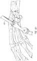
- FIG. 2Ais a side perspective view of an example placer.
- FIG. 2Bis a first end and side perspective view of the placer of FIG. 2A .
- FIG. 2Cis a second end and side perspective view of the placer of FIG. 2A .
- FIG. 3Ais a side and bottom perspective view of an example drill bit.
- FIG. 3Bis a side perspective view of the drill bit of FIG. 3A .
- FIG. 3Cis a bottom plan view of the drill bit of FIG. 3A .
- FIG. 3Dis a top and side perspective view of the drill bit of FIG. 3A .
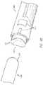
- FIG. 4Ais a side and bottom perspective view of an example introducer.
- FIG. 4Bis a side and top perspective view of the introducer of FIG. 4A .
- FIG. 5Ais a side and bottom perspective view of an example plunger.
- FIG. 5Bis a side perspective view of the plunger of FIG. 5A .
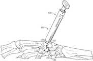
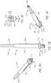
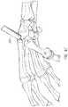
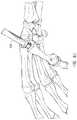
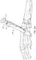
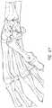
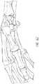
- FIGS. 6A-6Zschematically illustrate an example method of positioning an example carpometacarpal implant.
- a cartilage implantas well as various tools, systems, and methods related thereto.
- a number of these devices and associated treatment methodsare particularly well suited to replace deteriorated or otherwise damaged cartilage within a joint.
- Such implantsare configured to remain within the patient's joint on a long-term basis (e.g., for most or all of the life of the patient or subject), and, as such, are configured, in some embodiments, to replace native cartilage.
- an implantis configured to be substantially non-biodegradable and/or non-erodable.
- an implantis configured to remain within the patient's joint or other portion of the anatomy for a minimum of 10 years, up to 100 years (e.g., about 10 years, about 20 years, about 25 years, about 30 years, about 35 years, about 40 years, about 45 years, about 50 years, about 55 years, about 60 years, about 65 years, about 70 years, about 75 years, about 80 years, about 85 years, about 90 years, about 95 years, about 100 years, duration ranges between the foregoing values, etc.) without losing structural and/or physical properties and/or without losing ability to function as a cartilage replacement component or device.
- 100 yearse.g., about 10 years, about 20 years, about 25 years, about 30 years, about 35 years, about 40 years, about 45 years, about 50 years, about 55 years, about 60 years, about 65 years, about 70 years, about 75 years, about 80 years, about 85 years, about 90 years, about 95 years, about 100 years, duration ranges between the foregoing values, etc.
- an implantis configured to remain within the anatomy for greater than 100 years without losing structural and/or physical properties and/or without losing ability to function as a cartilage replacement component.
- Certain implants described hereincan be used to treat osteoarthritis, rheumatoid arthritis, other inflammatory diseases, generalized joint pain, joints damaged in an accident, joints damaged while participating in athletics, joints damaged due to repetitive use, and/or other joint diseases.
- the various devices, systems, methods, and other features of the embodiments disclosed hereinmay be utilized or applied to other types of apparatuses, systems, procedures, and/or methods, including arrangements that have non-medical benefits or applications.
- Certain embodiments described hereinmay be advantageous because they include one, several, or all of the following benefits: (i) improved treatment of the carpometacarpal joint; (ii) improved coupling of disparate implant materials; (iii) improved cavity wall apposition; (iv) improved implant site preparation tooling and/or systems; (v) improved implant site preparation methods; (vi) improved implant deployment tooling and/or systems; and/or (vii) improved implant deployment methods.
- Thumb arthritis or basal joint arthritiscan be caused by cartilage in the joint at the base of the thumb wearing out or being damaged. Thumb arthritis can cause debilitating hand pain, making simple tasks, such as turning door knobs, sink faucets, and other activities, difficult. Treatment has generally been limited to immobilization, pain relief medicaments, removal of the trapezium, and/or ligament reconstruction and tendon interposition (LRTI). While these treatments may reduce pain, they inhibit function of the thumb and the hand and may result in further or ongoing medicament use. Devices (e.g., implants), systems, kits, and methods described herein can provide a treatment for thumb arthritis that preserves the trapezium.
- LRTIligament reconstruction and tendon interposition
- FIG. 1Ais a bottom and side perspective view of one embodiment of a carpometacarpal (CMC) implant 100 .
- FIG. 1Bis a top and side perspective view of the implant 100 of FIG. 1A .
- FIG. 1Cis a top plan view of the implant 100 of FIG. 1A .
- the implant 100comprises, or alternatively consists essentially of, a hydrogel, such as, for example, polyvinyl alcohol (PVA), other polymeric materials, and/or the like.
- PVApolyvinyl alcohol
- the PVA content of a hydrogelis about 40% by weight.
- the PVA content of hydrogel in an implant 100can be less than or more than about 40% by weight (e.g., about 10%, about 15%, about 20%, about 25%, about 30%, about 32%, about 34%, about 36%, about 37%, about 38%, about 39%, about 41%, about 42%, about 43%, about 44%, about 46%, about 48%, about 50%, about 55%, about 60%, about 65%, about 70%, less than about 10%, more than about 70%, ranges between such values, etc.), as desired or required.
- 40% by weighte.g., about 10%, about 15%, about 20%, about 25%, about 30%, about 32%, about 34%, about 36%, about 37%, about 38%, about 39%, about 41%, about 42%, about 43%, about 44%, about 46%, about 48%, about 50%, about 55%, about 60%, about 65%, about 70%, less than about 10%, more than about 70%, ranges between such values, etc.
- the hydrogel of the implant 100can comprise water, saline, other liquids, combinations thereof, and/or the like.
- salinemay be used instead of water, because, under certain circumstances, saline can help maintain osmotic balance with surrounding anatomical tissues following implantation.
- the exact composition of hydrogel in an implant 100e.g., PVA or other hydrogel materials, water, saline or other liquids, other additives, etc.
- any hydrogel portion of the implants disclosed hereinconsist essentially of saline and PVA. In some embodiments, such hydrogel portions of the implants do not comprise any additional additives (e.g., growth factors, surface or other coatings, etc.). In addition, according to some embodiments, the hydrogel portions of any of the implant configurations disclosed herein comprise a consistent concentration (e.g., no concentration gradients), density, and/or other chemical and/or physical properties throughout.
- the implant 100is configured or adapted for drug delivery and/or is seeded with growth factors and/or cells.
- the implant 100comprises one or more of the following: chondrocytes, growth factors, bone morphogenetic proteins, collagen, hyaluronic acid, nucleic acids, and stem cells.
- chondrocytesgrowth factors
- bone morphogenetic proteinsgrowth factors
- collagenhyaluronic acid
- nucleic acidsnucleic acids
- stem cellsstem cells.
- Such factors and/or any other materials included in the implant 100 and selectively delivered to an implant sitecan help facilitate and/or promote the long-term fixation of the implant 100 at the joint or other target area of the anatomy.
- the hydrogelcomprises PVA and/or any other polymeric material.
- the content of PVA in the hydrogelis between about 35% and about 45% by weight (e.g., about 35%, about 36%, about 37%, about 38%, about 39%, about 40%, about 41%, about 42%, about 43%, about 44%, about 45%, ranges between such values, etc.).
- the content of PVA in the hydrogelis greater than about 45% by weight (e.g., about 45%, about 50%, about 55%, about 60%, about 65%, about 70%, greater than about 70%, ranges between such values, etc.) or less than about 35% by weight (e.g., about 5%, about 10%, about 15%, about 20%, about 25%, about 30%, about 35%, ranges between such values, less than about 5%, etc.).
- the content of PVA or other component in the hydrogelis about 40% by weight.
- the implant 100is load bearing and generally non-biodegradable (e.g., non-bioerodible).
- the implant 100is configured or adapted for placement in at least one of a toe, finger, ankle, knee, shoulder, hip, or any other joint, preferably a carpometacarpal joint and more preferably between a first metacarpal bone and a trapezium.
- a transition between the upper surface 102 and the sidewalls 106is generally arcuate, curved, or otherwise smooth, for example compared to including an angle or corner. In some embodiments, such a transition can be non-curved or non-smooth, as desired or required.
- the implants disclosed hereinare configured for anchoring during implantation.
- the implantcan comprise one or more anchor sites (e.g., comprising non-hydrogel portions or tabs) to facilitate anchoring (e.g., suturing, stapling, etc.).
- the implantis pre-coupled to one or more anchors.
- Such anchorscan comprise removable and/or permanent fixtures.
- the anchorsare resorbable or otherwise dissolvable after implantation (e.g., following a particular time period, such as, for instance, 1-30 days, 2-30 weeks, 6-12 months, 1-5 years, greater than 5 years, less than 1 day, etc.).
- the implantcomprises at least one abrasive surface.
- the implantcomprises one or more adhesive components.
- one or more implant surfacescan be configured to promote bone adhesion by one or more coatings, substances, and/or the like and/or by using an appropriate surface texture along the surface(s).
- the implant surfacecan be roughened, can include pores (e.g., superficial pores), and/or can include any other feature, as desired or required.
- the implants disclosed hereinare supported or reinforced by a rigid support frame, such as a ceramic, metallic, or other type (e.g., plastic, composite, etc.) of frame.
- the implants disclosed hereinare supported or reinforced by a flexible or rigid mesh structure.
- the implantsdo not contain or are substantially free or free of any support or reinforcement structure.
- any of the implant embodiments disclosed herein, or equivalents thereof,can be manufactured using freeze/thaw cycling and/or any other production method.
- a hydrogel formulationcomprising water, saline, PVA (and/or other hydrogel materials), other polymeric materials, other additives, and/or the like can be heated and/or otherwise treated as part of a freeze/thaw manufacturing process.
- a hydrogel solutioncomprising saline and about 40% PVA by weight is heated to about 121° C. under elevated pressure conditions (e.g., to effect dissolution of the polymer).
- elevated pressure conditionse.g., to effect dissolution of the polymer.
- such a solutioncan be autoclaved to facilitate complete or substantially complete dissolution of the PVA in the saline, water, and/or other liquid.
- the temperature and/or pressure of the solutioncan be lowered to permit entrapped air and/or other gases to escape.
- the solutionis generally maintained at a temperature of approximately 95° C. and atmospheric pressure for a predetermined time period.
- the solutioncan then be transferred (e.g., pumped, poured, etc.) into an open mold where, once set, the solution forms the desired shape of the implant.
- the moldcan include a plurality of individual mold cavities, each of which is configured to receive a hydrogel solution to form an implant.
- the hydrogel solutionmay be configured to fill only a lower portion of a cavity of a mold, or the cavity can be filled with the hydrogel solution to a level above the lower portion of the cavity including an upper portion of the cavity.
- the cavity of the moldcan be shaped, sized, and/or otherwise configured so that the implant formed therein comprises a desired configuration. Once the implant has been molded, the implant can be removed from the mold.
- the implantcan be removed either after initial formation or after undergoing additional treatment (e.g., freeze/thaw cycling, other heat and/or pressure treatment, etc.).
- additional treatmente.g., freeze/thaw cycling, other heat and/or pressure treatment, etc.
- the implantmay be cut, altered, or otherwise processed. For example, a portion of the implant formed in an upper portion of the cavity may be excised and discarded as part of a subsequent reshaping step.
- the amount of contraction or expansion of the implantcan be based on one or more factors or conditions, such as, for example, the number of freeze/thaw cycles to which the implant is subjected, the temperature and/or pressure ranges associated with the remaining steps, and/or the like.
- the implantcan be formed, at least in part, using an injection molding process and/or any other molding or casting procedure.
- injection or transfer molding techniquesonce the hydrogel or other implant solution has been prepared, the solution can be loaded into an injection cylinder or other container of a molding press. The solution can then be forcibly transferred into a closed mold assembly using a pneumatic or hydraulic ram or any other electromechanical device, system, and/or method.
- the hydrogel and/or other solution or implant componentis injected into a corresponding closed mold assembly through a standard runner and gate system.
- Injection molding of implantscan provide one or more benefits relative to open mold assemblies.
- an implant formed using an injection molding techniquemay be substantially free of or free of additional cutting, reshaping, resizing, and/or processing, due to being in essentially a final shape after completion of injection molding.
- the implantcan be subsequently subjected to one or more freeze/thaw cycles, as desired or required.
- an implant in a mold cavityis cooled using a total of four freeze/thaw cycles in which the temperature is sequentially varied between about ⁇ 20° C. and about 20° C.
- the number of freeze/thaw cycles, the temperature fluctuation, and/or other detailscan be different than disclosed herein, in accordance with a specific production protocol and/or implant design.
- the implantcan be at least partially removed (e.g., including fully removed) from the mold and placed in one or more saline and/or other fluid (e.g., other liquid) baths where the implant can be subjected to additional cooling and/or other treatment procedures (e.g., to further stabilize the physical properties of the implant).
- additional cooling and/or other treatment procedurese.g., to further stabilize the physical properties of the implant.
- the implantundergoes an additional eight freeze/thaw cycles while in saline.
- follow-up cooling procedurescan be either different (e.g., more or fewer freeze/thaw cycles, different type of bath, etc.) or altogether eliminated from the production process, as desired or required.
- the implantscan be inspected for any manufacturing flaws or other defects. At least some of the implants can be subjected to selective testing for physical and other characteristics, in accordance with the original design goals and/or target parameters.
- the implantmay be cut or otherwise processed to remove any excess portions (e.g., flash).
- one or more completed implant(s)is packaged in hermetically sealed plastic trays or other containers comprising foil or other types of lids or covering members. A volume of saline and/or other liquid can be included within such trays or other containers to provide hydration of the implant(s) during storage and/or any other steps preceding use.
- the implant tray or other containeris terminally sterilized using e-beam exposure between about 25 kilogray (kGy) and about 40 kGy.
- the implant 100has a lateral dimension (e.g., diameter) between about 4 mm and about 8 mm (e.g., about 4 mm, about 5 mm, about 6 mm, about 7 mm, about 8 mm, ranges between such values, etc.), as measured in an uncompressed state. Lateral dimensions smaller than about 4 mm (e.g., between about 2 mm and about 4 mm) and larger than about 8 mm (e.g., between about 8 mm and about 10 mm) are also possible for use in subjects with small or large bones, respectively.
- a lateral dimensione.g., diameter
- the implant 100comprises, or alternatively consists essentially of, or alternatively consists of, a top or upper surface 102 , a bottom or lower surface 104 generally opposite the upper surface 102 , and a hydrogel body between the upper surface 102 and the lower surface 104 .
- the implant 100comprises a hydrogel (e.g., PVA) implant 100 or any other type of substrate-based implant 100 .
- the implant 100is capable of being used and/or is configured to be used in a joint treatment method as disclosed herein, modifications thereof, and/or other methods.
- sidewalls 106generally extend between the upper surface 102 and the lower surface 104 .
- the implant 100is configured for placement in an implant site having a corresponding recess.
- the overall height (e.g., between the top surface 102 and the bottom surface 104 ) of the implant 100is between about 4 mm and about 8 mm (e.g., about 4 mm, about 5 mm, about 6 mm, about 7 mm, about 8 mm, ranges between such values, etc.), as measured in an uncompressed state. Heights smaller than about 4 mm (e.g., between about 2 mm and about 4 mm) and larger than about 8 mm (e.g., between about 8 mm and about 10 mm) are also possible for use in subjects with small or large bones, respectively.
- the upper surface 102may be configured to form an articulation surface when the implant 100 is implanted in a joint.
- the upper surface 102can comprise a contour configured to correspond to contours of a lower surface of a first metacarpal bone (facing the trapezium) and/or an upper surface of a trapezium (facing the first metacarpal bone).
- the upper surface 102has a saddle shape comprising peaks 118 a , 118 b and troughs 120 a , 120 b .
- the contours of the upper surface 102are illustrated by line contours in FIG. 1C .
- the contours of the upper surface 102 of the implant 100may be modified to match a specific anatomy (e.g., a surface (e.g., inferior surface) of a trapezium).
- a surface of a bone (e.g., first metacarpal bone) and/or an opposing bone (e.g., trapezium)may be scanned (e.g., via computerized tomography (CT), computerized axial tomography (CAT), positron emission tomography (PET), magnetic resonance imaging (MRI), combinations thereof, etc.), which can be used to make a mold (e.g., via 3D printing, CAD-CAM milling, etc.) to match specific anatomical features of a specific patient or subject, which can be advantageous, for example, when the anatomy has been damaged or otherwise includes unique characteristics.
- CTcomputerized tomography
- CATcomputerized axial tomography
- PETpositron emission tomography
- MRImagnetic resonance imaging
- the upper surface 102comprises, or alternatively consists essentially of, or alternatively consists of, a saddle shape including a first peak 118 a , a second peak 118 b , a first trough 120 a laterally between the first peak 118 a and the second peak 118 b , and a second trough 120 b laterally between the first peak 118 a and the second peak 118 b .
- the first peak 118 ais laterally between the first trough 120 a and the second trough 120 b .
- the second peak 118 bis laterally between the first trough 120 a and the second trough 120 b .
- a distance between the first peak 118 a and/or the second peak 118 b and the lower surface 104is between about 10% and about 20% greater than a distance between at least one of the first trough 120 a and the second trough 120 b and the lower surface 104 .
- One or both of the peaks 118 a , 118 bmay be between about 1 mm and about 1.5 mm (e.g., about 1 mm, about 1.1 mm, about 1.2 mm, about 1.3 mm, about 1.4 mm, about 1.5 mm, ranges between such values, etc.) higher than one or both of the troughs 120 a , 120 b.
- the implant 100is illustrated as a substantially cylindrical plug or shape, other shapes of the implant 100 are also possible.
- an upper surface 102 and/or the lower surface 104may be contoured to abut particular anatomy (e.g., planar (e.g., flat), non-planar (e.g., curved, concave, convex, undulating, fluted)) and/or modified anatomy (e.g., a recess formed in a bone).
- the implant 100can include a generally circular or oval cross-sectional shape.
- the implant 100is generally shaped like a cylinder.
- the overall shape of any of the implants disclosed hereincan vary depending on the specific application or use.
- the shape of at least part of the implant 100can be generally polygonal (e.g., rectangular, round, hexagonal), irregular, and/or the like.
- the implant 100lacks, is devoid of, is substantially free of, etc. attachment tabs or other features configured to fix the implant 100 in place.
- the implant 100may maintain position by being slightly oversized with respect to a cavity in which a portion of the implant 100 is positioned.
- the implant 100lacks, is devoid of, is substantially free of, etc. surface contours on the bottom surface 104 .
- the implant 100may lack configuration to be placed between a first metacarpal bone and a trapezium without forming a cavity in the first metacarpal bone.
- the implant 100lacks, is devoid of, is substantially free of, etc. an upper surface 102 configured to replace a bone or an end of a bone.
- the implant 100may be configured to replace part of an end surface of a bone (e.g., a central portion, a bearing surface, etc.), but not to replace the entire bone and/or the end surface.
- FIGS. 2A-5Billustrate example tooling or systems that may be used to deploy the implant 100 in a carpometacarpal joint such as between the first metacarpal bone and the trapezium.
- the implant 100 or variations thereofmay also be used at other joints.
- a plurality of implantse.g., the implant 100
- FIGS. 6A-6Zillustrate or explain an aspect, potential advantage, etc. of a tool or system.
- One or more of the toolscan be used in combination with a substantially cylindrical, elongate guide pin having a sharpened end (or another guiding device), which can aid in alignment of the tools throughout a treatment method.
- the bone anchormay fit in a hole created by the guide pin. Absence of a guide pin or other guiding device is also possible.
- FIGS. 2A-3Dillustrate example components of a system, for example, usable to create a cavity into which the implant 100 may be inserted.
- the introducer placer 200 of FIGS. 2A-2Cmay be used in combination with a drill bit or other system different than the drill bit 300 of FIGS. 3A-3D .
- the drill bit 300 of FIGS. 3A-3Dmay be used in combination with a placer or other system different than the placer 200 of FIGS. 2A-2C .
- Other systems and methods for creating a cavityare also possible, including modifications to the placer 200 and/or the drill bit 300 .
- the spacer 200 and/or drill bit 300may be used in combination with the introducer 400 of FIGS. 4A and 4B , other introducers, the plunger 500 of FIGS. 5A and 5B , other plungers, or other systems.
- FIG. 2Ais a side perspective view of an example placer 200 .
- the placer 200comprises a first end 202 , a second end 204 generally opposite the first end 202 , and a body 206 extending between the first end 202 and the second end 204 .
- the body 206is generally cylindrical, although other shapes are also possible (e.g., having an elliptical cross-section, having a polygonal cross-section, etc.).
- the placer 200can comprise stainless steel (e.g., surgical grade stainless steel), plastic, combinations thereof, and/or the like.
- FIG. 2Bis a first end 202 and side perspective view of the placer 200 of FIG. 2A .
- the first end 202has a saddle shape comprising peaks 218 a , 218 b and troughs 220 a , 220 b .
- the contours of the first end 202are illustrated by line contours in FIG. 2B .
- the contours of the first end 202may be modified to match a specific anatomy (e.g., a surface (e.g., inferior surface) of a trapezium) and/or anatomy of a specific patient or subject (e.g., using scanning and manufacturing process as described herein).
- the first end 202 of the placer 200may be exchangeable (e.g., using a first end 202 configured to engage a standard body 206 using threads or other attachment mechanism).
- the first end 202is substantially flat or planar.
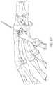
- FIG. 2Cis a second end 204 and side perspective view of the placer 200 of FIG. 2A .
- the second end 204is substantially flat or planar.
- the second end 204has a shape configured to correspond to a shape created by a certain drill bit.
- the second end 204 of the placer 200may be exchangeable (e.g., using a second end 204 configured to engage a standard body 206 using threads or other attachment mechanism).
- the body 206may comprise a substantially cylindrical body having threads or other coupling mechanisms at one or both ends for coupling to a modular first end 202 (e.g., for different anatomies) and/or a modular second end 204 (e.g., for different drill bits).
- the threads or other coupling mechanisms at one or both endsmay be the same (e.g., to allow either side of the body 206 to be used for the first end 202 or the second end 204 ) or different (e.g., to inhibit or prevent use of different sides of the body 206 for the same ends 202 , 204 ).
- the placer 200includes a lumen 208 in the body 206 between the first end 202 and the second end 204 .
- the lumen 208is configured to accept a guide pin therethrough, for example as described with respect to FIG. 6E .
- the lumen 208may be centered in the body 206 or may be radially offset.
- the body 206comprises a plurality of lumens (e.g., allowing a user to select a lumen based on the interaction of the first end 202 of the spacer 200 with the anatomy).
- the drill bit 300can be advanced to the targeted drill site of the patient bone or other anatomical location with the assistance of a guide pin or other guiding device or member.
- a cannulated drill bit 300as discussed herein, can be passed over the guide pin to ensure that the distal, working end 302 of the drill bit 300 is properly positioned relative to the treatment site (e.g., bone, joint).
- the placer 200may comprise, for example proximate to the second end 204 , a plurality of arcuate bands 210 a , 210 b , 210 c , 210 d , 210 e that can be used to measure depth of a cavity, for example a cavity resulting from drilling into bone.
- the band 210 amay correspond to a depth from the second end 204 of about 6 mm
- the band 210 amay correspond to a depth from the second end 204 of about 6 mm
- the band 210 bmay correspond to a depth from the second end 204 of about 7 mm
- the band 210 cmay correspond to a depth from the second end 204 of about 8 mm
- the band 210 dmay correspond to a depth from the second end 204 of about 9 mm
- the band 210 emay correspond to a depth from the second end 204 of about 10 mm
- the bands 210 a , 210 b , 210 c , 210 d , 210 ebeing spaced by about 1 mm.
- the bands 210 a , 210 b , 210 c , 210 d , 210 emay be spaced by about 0.1 mm, about 0.2 mm, about 0.3 mm, about 0.4 mm, about 0.5 mm, about 0.6 mm, about 0.7 mm, about 0.8 mm, about 0.9 mm, about 1 mm, about 1.1 mm, about 1.2 mm, about 1.3 mm, about 1.4 mm, about 1.5 mm, about 1.6 mm, about 1.7 mm, about 1.8 mm, about 1.9 mm, about 2 mm, greater than about 2 mm, combinations thereof, and the like.
- the plurality of bandsmay comprise between four bands and six bands (e.g., four, five, six, ranges between such values, etc.). More bands (e.g., between six bands and ten bands) or fewer bands (e.g., between one band and four bands) are also possible.
- the bandsmay start closer to the second end 204 (e.g., about 0.1 mm, about 0.5 mm, about 1 mm, etc. from the second end 204 ).
- the bandsmay be fully arcuate (e.g., extending around part of the circumference of the body 206 ) and/or partially arcuate (e.g., extending around part of the circumference of the body 206 ).
- the bandsmay each be the same or may be different from each other.
- the bandsmay be used to measure a depth of a drilled hole in a bone, for example as described in further detail with respect to FIG. 6K .
- the bandsmay comprise distinguishing indicia.
- the bandsmay comprise different dash patterns (e.g., a dotted band 210 a , a solid band 210 b , a dashed band 210 c , a solid band 210 d , and a dotted band 210 e ), different colors (e.g., different colors in the color palette, different shades, etc.), numbers (e.g., indicative of depth, band number, etc.), combinations thereof, and the like.
- the placer 200may comprise the features described herein with respect to one or both of the first end 202 (e.g., a saddle shape) and the second end 204 (e.g., measurement bands).
- a first toolcan include the features of the first end 202 and a second, separate, tool can include the features of the second end 204 .
- FIG. 3Ais a side and bottom perspective view of an example drill bit 300 .
- FIG. 3Bis a side perspective view of the drill bit 300 of FIG. 3A .
- FIG. 3Cis a bottom plan view of the drill bit 300 of FIG. 3A .
- FIG. 3Dis a top and side perspective view of the drill bit 300 of FIG. 3A .
- the drill bit 300can be used to create a recess or hole or cavity or aperture or crater or pit or pocket in a bone, for example in which an implant 100 can be placed.
- the drill bit 300comprises, or alternatively consists essentially of, a distal end 302 , a proximal end 304 generally opposite the distal end 302 , and a body 306 extending between the distal end 302 and the proximal end 304 .
- the drill bit 300may comprise, for example, stainless steel.
- the body 306 of the drill bit 300includes a generally cylindrical distal section 306 a and a polygonal proximal section 306 b .
- the cylindrical distal section 306 amay provide strength to the drill bit 300 and/or reduce eccentricity during drill rotation.
- the polygonal proximal section 306 bis sized, shaped, and otherwise configured to selectively mate with a corresponding portion of a bone drill (not shown).
- the proximal section 306 bcomprises a generally triangular cross-sectional area, but other shapes, sizes, and/or other details of the proximal section 306 b can vary.
- Bone drills with which the drill bit 300 or variations thereof can be coupledmay be manually operated and/or power driven (e.g., mechanically, pneumatically, hydraulically, etc.).
- the distal end 302 of the drill bit 300can include a flange 312 and one or more abrading members or blades or cutters 310 a , 310 b , 310 c extending distally from the flange 312 .
- the drill bit 300can comprise a total of three cutters 310 a , 310 b , 310 c that are generally equally spaced apart (e.g., at angles of approximately 120° relative to each other).
- the quantity, size, shape, position, orientation, spacing, and/or other characteristics or properties of the cutters 310can vary.
- a drill bitcan include more than three cutters or fewer than three cutters (e.g., 1, 2, 4, 5, more than 5, etc.), as desired or required.
- a drill bitcan include cutters that are larger and/or smaller, that extend along different portions of the distal end of the drill bit, combinations thereof, and the like.
- the flange 312can provide a non-cutting “stop” surface that can inhibit the drill bit 300 from cutting below a certain depth, even if further rotation and pressure are applied. The flange 312 can aid in removal of cut material, for example inhibiting or preventing cut material from spraying past the flange unabated.
- the drill bit 300comprises a lumen 308 extending (e.g., longitudinally) through the drill bit 300 .
- the lumen 308can generally extend from the distal end 302 to the proximal end 304 .
- a lumen 308can help ensure that the drill bit 300 is accurately positioned relative to a joint, bone, and/or other portion of anatomy of a subject (e.g., over a guide pin) before commencing and/or during a drilling procedure.
- sharp edges formed along the distal and/or peripheral portions of the cutters 310 a , 310 b , 310 ccan abrade and remove cartilage, bone, and/or other tissue.
- the longitudinal distance between the distal face of the flange 312 and the distal ends of the cutters 310 a , 310 b , 310 ccan limit the depth of the recess or opening that is created by the drill bit 300 .
- Peripheral surfaces of the cutters 310 a , 310 b , 310 ccan define a diameter ⁇ c ( FIG.
- the drill bit 300can thereby be configured to create an implant site having specific dimensions (e.g., depth, diameter, etc.).
- drill bits of varying size and shapeare available to the surgeon or other clinician in order to accurately create a specific desired implant site.
- the distal edges and/or other surfaces of the cutting blades or cutterscan be generally flat and/or otherwise contoured (e.g., to generally match and/or receive the base of the implant).
- the flange 312can include one or more openings, for example in the form of through holes, channels, edge features, etc. Abraded materials can stay clear of and not interfere with the working end of the drill bit 300 , allowing the cutters 310 a , 310 b , 310 c to continue to function normally. Once the distal face of the flange 312 abuts the top surface of the bone being drilled, further advancement of the drill bit 300 can be inhibited or prevented. Resistance to further advancement can alert the clinician that an implant site having the desired depth and diameter has been properly created.
- the cutters 310 a , 310 b , 310 ccan be joined along a hub 314 along or near the center of the distal face of the flange 312 . As shown, the cutters 310 a , 310 b , 310 c can extend at least radially outwardly from the hub 314 , toward the outer periphery of the flange 312 . The radial length of the cutters 310 a , 310 b , 310 c can help determine a diameter of a recess or opening created by the drill bit 300 .
- the corresponding opening created by the drill bit 300is generally cylindrical.
- the cutterscan extend distally from a distal-facing surface, such as the distal-facing surface of the flange 312 , without a hub 314 .
- FIGS. 4A-5Billustrate example components of a deployment system or delivery device, for example usable to deploy the implant 100 .
- the introducer 400 of FIGS. 4A and 4Bmay be used in combination with a plunger or other system different than the plunger 500 of FIGS. 5A and 5B .
- the plunger 500 of FIGS. 5A and 5Bmay be used in combination with an introducer or other system different than the introducer 400 of FIGS. 4A and 4B .
- Other systems and methods for deploying or delivering an implantare also possible, including modifications to the introducer 400 and/or the plunger 500 .
- the introducer 400 and/or plunger 500may be used in combination with the placer 200 of FIGS. 2A-2C , other placers, the drill bit 300 of FIGS. 3A-3D , other placers, or other systems.
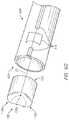
- FIG. 4Ais a side and bottom perspective view of one embodiment of an introducer 400 .
- the introducer 400can comprise, or alternatively consist essentially of, a distal end 402 , a proximal end 404 generally opposite the distal end 402 , and a generally cylindrical tube 406 having an opening or lumen 408 through which an implant (e.g., the implant 100 ) may be passed.
- the distal end 402 of the introducer 400comprises a neck portion or other narrowed portion 410 .
- the neck portion 410is configured to be positioned at least partially in a recess created by a drill bit and in which an implant will be at least partially secured.
- the introducer 400is sized, shaped, and otherwise configured to that the neck portion 410 fits generally snugly within the implant site.
- the shoulder 412 or other feature where the introducer 400 returns to the normal or nominal or larger diametercan act as a depth stop, which can ensure that the implant is positioned in the recess.
- the shoulder 412can help protect the structural integrity of the implant as the implant is being deployed.
- the shoulder 412comprises a distally-facing surface that is substantially flat or planar (e.g., as illustrated in FIG. 4A ).
- the shoulder 412comprises a distally-facing surface that is contoured (e.g., to correspond to an undrilled surface of a first metacarpal bone).
- the body 406may comprise a substantially cylindrical body having threads or other coupling mechanisms for coupling to a modular distal end 402 (e.g., for different anatomies).
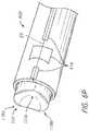
- FIG. 4Bis a side and top perspective view of the introducer 400 of FIG. 4A .
- the internal diameter of the introducer 400can vary along its longitudinal length.
- the proximal end 404 of the introducer 400comprises, at least partially, a flared shape 414 in which at least a portion of the inside diameter of the lumen 408 is progressively reduced in the proximal to distal direction.
- the lumen 408can maintain a generally constant inner diameter distal to the flared shape 414 forming a generally cylindrical interior portion.
- the lumen 408can have a diameter that his smaller than a diameter of an uncompressed implant such that the implant is radially inwardly compressed as the implant is distally advanced through the flared shape 414 .
- compression of the implantmay aid in deployment of the implant by allowing the compressed implant to be positioned in a recess in bone having a smaller diameter than a diameter of the uncompressed implant, which can allow the implant to radially outwardly expand to provide apposition against sidewalls of the recess.
- compression of the implantmay inhibit the implant from falling out of the introducer 400 during deployment (e.g., due to apposition of the implant against sidewalls of the lumen 408 ).
- the introducer 400comprises alignment indicia 416 configured to align an implant having a contoured surface (e.g., a contoured upper surface) before and/or during deployment.
- a contoured surfacee.g., a contoured upper surface
- the trough 120 a or 120 b of an implant 100 having a saddle shapemay be aligned with the indicia 416 at the proximal end 404 of the introducer 400 .
- the indicia 416may include pictures or other terms indicative of what should be aligned (e.g., a trough shape as shown in FIG. 4A , the term “trough,” combinations thereof, and the like). As described with respect to FIGS.
- the trough 20 a or 20 b of a bone surface having a saddle shapemay be aligned with the indicia 416 at the distal end 402 of the introducer 400 .
- compression of the implantcan inhibit or prevent rotation of the implant in the introducer 400 such that alignment at the proximal end 404 can provide alignment at the distal end 402 .
- the peak 118 a or 118 b of an implant 100 having a saddle shapemay be aligned with the indicia 416 .
- the lumen 408may have a corresponding lateral cross-section, which can inhibit or prevent rotation of the implant in the introducer 400 such that alignment at the proximal end 404 can provide alignment at the distal end 402 .
- the introducer 400comprises a viewing window that permits an implant to be viewed as it is advanced through the introducer 400 , for example prior to and/or during deployment.
- the viewing windowcan be separate or integrated as part of the alignment indicia 416 .
- the alignment indicia 416may comprise ink, etching, and/or windows (e.g., comprising unfilled slits and/or a biologically compatible non-opaque or at least partially optically transparent material).
- the inner diameter, length, other dimension, and/or other details or properties of the introducer 400can be different than shown and described herein.
- the flared shape 414can extend along more, or even all or substantially all, of the length of the lumen 408 .
- the interior surface of the body 406may be at least partially non-linear (e.g., curved, rounded, irregular, etc.), in addition to or in lieu of any generally linear and/or constant portions, as desired or required.
- the longitudinal axis of the introducer 400(and the longitudinal axis along which the implant is advanced through the introducer 400 ) is substantially perpendicular or perpendicular with or at another desired angle to the surface of the bone or other anatomical site (e.g., bottom of the recess) into which the implant will be delivered and/or the distal end 402 or a portion thereof is substantially parallel or parallel to a longitudinal axis of the bone or other anatomical structure (e.g., longitudinal axis of the recess).
- At least a portion of the interior of the introducer 400comprises and/or is coated or lined with one or more absorbable or lubricious layers, materials, and/or other substances. Such materials can help preserve a moisture level of the implant during deployment.
- the interior surface of the introducer 400can comprise a low coefficient of friction to facilitate the delivery of an implant through the lumen 408 .
- reducing an effective coefficient of friction along the interior of the introducer 400can comprise polishing the interior surfaces of the introducer 400 .
- the introducer 400including interior surfaces, can comprise stainless steel (e.g., surgical grade stainless steel), titanium, other metals and/or alloys, plastic, combinations thereof, and/or the like.
- FIG. 5Ais a side and bottom perspective view of an example plunger 500 .
- FIG. 5Bis a side perspective view of the plunger 500 of FIG. 5A .
- the plunger 500may be used in combination with the introducer 400 to form a deployment system.
- the plunger 500comprises, or alternatively consists essentially of, a distal end 502 , a proximal end 504 generally opposite the distal end 502 , and a body 506 between the distal end 502 and the proximal end 504 .
- the distal end 502has a saddle shape comprising peaks 518 a , 518 b and troughs 520 a , 520 b .
- the contours of the distal end 502 are of the plunger 500may be modified to match a specific anatomy (e.g., a surface (e.g., inferior surface) of a trapezium).
- the body 506may comprise a substantially cylindrical body having threads or other coupling mechanisms for coupling to a modular distal end 502 (e.g., for different anatomies).
- a modular distal endcan be used as the distal end 202 of the spacer 200 and the distal end 502 of the plunger 500 . As described with respect to FIGS.
- the peaks 118 a , 118 b and troughs 120 a , 120 b of an implant 100 having a saddle shapemay be aligned with the peaks 518 a , 518 b and troughs 520 a , 520 b of the distal end 502 of the plunger 500 .
- a properly seated plunger 500e.g., with the contours of the distal end 502 aligned with the contours of an implant
- the plunger proximal end 504 of the plungermay comprise indicia 516 .
- the indicia 516may include pictures or other terms indicative of what should be aligned (e.g., a trough shape as shown in FIGS. 5A and 5B , the term “trough,” combinations thereof, and the like). In some embodiments, if the indicia 516 are aligned with the indicia 416 at the proximal end 404 of the introducer 400 (e.g., as shown in FIG. 6T ) and the plunger 500 is properly seated, then the implant can be expected to be aligned with the indicia 416 of the introducer 400 .
- pictures or other terms indicative of what should be alignede.g., a trough shape as shown in FIGS. 5A and 5B , the term “trough,” combinations thereof, and the like.
- the implantshould be properly aligned upon deployment.
- the proximal end 504e.g., the radially outward extending arms of a T-shape
- indicia 516may be used as indicia 516 .
- the proximal end 504 of the plunger 500may comprise an enlarged head portion 512 .
- the head portion 512is in a T-shape (e.g., as illustrated in FIGS. 5A and 5B ).
- the head portion 512comprises a ball, a flat surface, a handle, a grasping portion configured to be selectively gripped and manipulated, or any other surface suitable for engagement by a hand.
- the head portion 512is configured to engage an external power-assist device (e.g., mechanically, pneumatically, hydraulically, etc.), as desired or required.
- the body 506may comprise a substantially cylindrical body having threads or other coupling mechanisms for coupling to a modular proximal end 504 (e.g., for user preference of a manual handle, for optional connection to a power-assist device).
- the body 506may be the same as the body 206 , and modular first or distal ends 202 , 502 and/or second or proximal ends 204 , 504 may be coupled for use as a spacer or a head portion.
- a bodycan be coupled to a modular distal end and first modular proximal end for use as a spacer, after which the first modular proximal end can be exchanged with a second modular proximal end for use as a plunger.
- the bands for a spacer and the indicia for a plungermay be integrated with each other on the body, the bands may be part of a modular proximal end, and/or the indicia may be part of a modular distal end.
- Such embodimentscan reduce costs (e.g., because the same body is used for the spacer and the plunger and/or provide better alignment (e.g., because the same modular distal end is used to guide the drill bit and to deploy the implant). If the modular distal end of the plunger does not correspond to the proximal end of the implant, that could indicate a problem with the modular distal end and/or the implant, which could inhibit or prevent placement of improper implants that may be difficult to remove once deployed.
- the plunger 500includes a motion limiter or depth stop.
- the motion limitercan comprise one or more knobs, protrusion members, and/or other features that generally extend outwardly from the body 506 and/or the head portion 512 .
- a motion limiteris configured to slide in a portion of the lumen 408 of the introducer 400 (e.g., in the flared shape 414 but not distal thereto).
- a motion limitercan help inhibit or prevent distal movement of the plunger 500 relative to the introducer 400 (e.g., when the motion limiter contacts or abuts a surface of the introducer 400 ).
- a motion limitedcan help inhibit or prevent rotation of the plunger 500 relative to the introducer 400 during use, which can aid in proper alignment and positioning of the implant during deployment.
- the body 506 of the plunger 500can comprise a generally cylindrical shape configured to fit through the lumen 408 of the introducer 400 (e.g., including distal to the flared shape 414 ).
- the body 506can have a lateral dimension (e.g., diameter) that is slightly smaller than a smallest lateral dimension (e.g., diameter) of the lumen 408 of the introducer 400 .
- a clinician, surgeon, or other usercan selectively move the plunger 500 within an interior portion of the introducer 400 in order to urge an implant (e.g., the implant 100 ) through the distal end 402 of the introducer 400 and in a targeted implant site.
- the body 506may be hollow (e.g., to reduce weight or material used, if the same as the body 206 ), solid (e.g., to increase strength or rigidity), and the like.
- the deployment system or delivery devicecomprises and/or is operatively coupled to one or more pressure gauges or other pressure or force measuring devices, members, and/or features.
- gauges or other measurement devicescan help ensure that a certain (e.g., maximum or threshold) backpressure or force is not exceeded when operating the device, which can help protect the integrity of an implant being deployed (e.g., to maintain the structural integrity, water composition, and/or other properties of the implant), protect the delivery device, protect the user and/or the subject, and/or provide one or more other advantages or benefits.
- the components of the delivery devicecan comprise one or more rigid and/or semi-rigid materials configured to withstand the forces, moments, chemicals, and/or other substances, temperature fluctuations, and/or other elements to which they may be exposed.
- the components of the implant delivery devicecan comprise one or more metals (e.g., stainless steel, surgical stainless steel, other types of steel, etc.), alloys, plastics, combinations thereof, and/or the like. Such materials can permit the device to be autoclaved, sterilized, or otherwise cleaned during a specific disinfection protocol.
- the structural and other physical characteristics of the devicecan permit the user to exert appropriate forces to deliver implants of various sizes, shapes, and/or configurations through the introducer and in a target implant site of a subject.
- a kitcomprises at least two of the placer, drill bit, introducer, plunger, and guide pin.
- the kitmay comprise the placer and drill bit; the placer and introducer; the placer and plunger; the placer and guide pin; the placer, drill bit, and introducer; the placer, drill bit, and plunger; the placer, drill bit, and guide pin; the placer, drill bit, introducer, and plunger; the placer, drill bit, introducer, and plunger; the placer, drill bit, introducer, and guide pin; the placer, drill bit, plunger, and guide pin; the drill bit and introducer; the drill bit and plunger; the drill bit and plunger; the drill bit and guide pin; the drill bit, introducer, and plunger; the drill bit, introducer, and guide pin; the drill bit, plunger, and guide pin; the drill bit, introducer, plunger; the introducer, plunger, and guide pin; the drill bit, introducer, plunger, and guide pin; the introducer and plunger; the introducer
- the kitcomprises at least two of means for placing an implant (e.g., the placer), means for forming a cavity (e.g., the drill bit), and means for deploying an implant (e.g., comprising the introducer and/or the plunger).
- the kitfurther comprises means for treating a joint (e.g., the implant).
- the kitcomprises a body having a proximal end and a distal end.
- the distal end of the bodycomprises a coupling feature (e.g., threads).
- the kitfurther comprises at least one modular distal end comprising a coupling feature (e.g., threads) complementary to the coupling feature of the distal end of the body.
- a distal surface of the modular distal endcomprises a saddle shape configured to correspond to a surface of an implant.
- the proximal end of the bodycomprises a coupling feature (e.g., threads).
- the kitfurther comprises at least one modular proximal end comprising a coupling feature (e.g., threads) complementary to the coupling feature of the proximal end of the body.
- the kitcomprises a plurality of modular proximal ends.
- a first modular proximal endmay comprise a substantially flat surface and depth bands and a second modular proximal end may comprise a T-shaped handle and implant alignment indicia.
- FIGS. 6A-6Zschematically illustrate an example method of positioning an example carpometacarpal implant 100 .
- the implant 100the placer 200 , the drill bit 300 , the introducer 400 , and the plunger 500 , as described above in detail, other implants, tools, systems, and methods are possible.
- positioning the implant 100 in a right handpositioning in the left hand is also possible.
- an incision 14is made proximate to (e.g., close enough to sufficiently access) the joint between the trapezium 10 and the first metacarpal bone 12 .
- the cartilage between the trapezium 10 and the first metacarpal bone 12has been worn out or damaged. Additional steps and/or other actions associated with a procedure, such, as, for example, sterilization, anesthesia, site preparation, and the like, may be used; however, details have been omitted from the description of the procedure herein for brevity.
- the thumb including the first metacarpal bone 12can be bent (e.g., downwardly) to expose the joint between the trapezium 10 and the first metacarpal bone 12 , including an end surface 16 of the first metacarpal bone 12 .
- Skin, muscle, ligaments, etc.are omitted from FIGS. 6B-6M and 6U-6Z for clarity.
- the end surface 16has a generally concave saddle shape including peaks 18 a , 18 b and troughs 20 a , 20 b .
- Surfaces of the implant 100 , the placer 200 , the introducer 400 , and/or the plunger 500may be contoured to correspond to a surface of one or more others of the implant 100 , the placer 200 , the introducer 400 , and/or the plunger 500 , a surface of a metacarpal bone, and/or a surface of a trapezium.
- a placer 200is advanced toward the end surface 16 through the incision 14 ( FIG. 6A ).
- the placer 200may be generally longitudinally aligned with the first metacarpal bone 12 .
- the first end 202 of the placer 200abuts the end surface 16 .
- a guide pin 22is advanced through the lumen 208 of the placer 200 and positioned in or “tamped” at least partially in the first metacarpal bone 16 .
- FIG. 6Eshows the guide pin 22 placed using the placer 200 . Placement of the guide pin 22 without a placer is also possible.
- the guide pin 22may be substantially parallel or parallel with a longitudinal axis of the first metacarpal bone 16 , at an angle (e.g., about 90°, less than about 90°, greater than about 90°) to the end surface 16 or a portion (e.g., a certain contour) thereof.
- the guide pin 22may be advanced through the anatomy using a trocar or similar device.
- FIGS. 6F-6Iillustrate the drill bit 300 forming a cavity or recess or hole or aperture or crater or pit or pocket 24 in the first metacarpal bone 12 .
- FIG. 6Fshows the drill bit 300 being tracked over the guide pin 22 towards the end surface 16 of the first metacarpal bone 12 .
- the guide pin 22can help ensure that the drill bit 300 is properly positioned relative to the treatment site (e.g., joint). Forming the cavity 24 without a guide pin 22 is also possible.
- FIG. 6Gshows the inception of formation of the cavity 24 due to rotation about the longitudinal axis of the drill bit 300 and distal longitudinal advancement towards the end surface 16 . In the embodiment of FIG.
- FIG. 6Ishows the drill bit 300 being proximally retracted over the guide pin 22 after forming the cavity 24 .
- the cavity 24has a diameter and depth based on the configuration of the drill bit 300 (e.g., dimensions of the cutters 310 a , 310 b , 310 c , the flange 312 , etc.).
- the lateral dimension (e.g., diameter) of the cavity 24is smaller than the lateral dimension (e.g., diameter) of the implant 100 , which may flex radially inwardly.
- the lateral dimension (e.g., diameter) of the implant 100may flex radially inwardly.
- other shapesare also possible (e.g., trapezoidal tapering inwards towards the upper surface).
- a lateral dimension and/or cross-sectional area of the cavity 24is about 5% to about 15% (e.g., about 5%, about 6%, about 7%, about 8%, about 9%, about 10%, about 11%, about 12%, about 13%, about 14%, about 15%, ranges between such values, etc.) narrower or otherwise smaller than the lateral dimension and/or cross-sectional area of the implant 100 .
- the cavity 24may be coated or otherwise treated prior to positioning of the implant 100 .
- FIGS. 6F-6Iillustrate the placer 200 being used to measure and/or check depth of the cavity 24 .
- the placer 200has been flipped so the second end 204 faces the cavity 24 .
- a separate toolis used.
- the placer 200is tracked over the guide pin 22 towards and, as shown in FIG. 6K , partially into the cavity 24 . Measurement of the cavity 24 without a guide pin 22 is also possible.
- the bands 210 a , 210 b , 210 c , 210 d , 210 eare used to measure the depth of the cavity 24 .
- the depthis measured at the peak 18 a
- a usercan visualize the last band that is visible over the peak 18 a (e.g., the band 210 c in FIG. 6K , corresponding to a depth of about 8 mm).
- the depthis measured at the peak 18 b , trough 20 a , trough 20 b , or some other portion of the end surface 16 . If the cavity 24 has an incorrect depth, if the second end 204 is not able to fit in the cavity 24 , or the second end 204 evidences other issues, the drill bit 300 or another drill bit can be used to correct the defect in the cavity 24 .
- FIG. 6Lshows the placer 200 being proximally retracted over the guide pin 22 after measuring the cavity 24 .
- FIG. 6Mshows the guide pin 22 being removed from the first metacarpal bone 12 .
- a sharp distal end of the guide pin 22which can pierce the bone during tamping and/or help to wedge the guide pin 22 through the bone, is visible.
- the bone anchormay fit in a hole created by the guide pin.
- FIGS. 6N-6Tshow preparation of the implant 100 for deployment using a deployment system comprising the introducer 400 and the plunger 500 .
- the deployment preparationcan be before, during, or after other steps of the procedure.
- a first usercan prepare the implant 100 for deployment while a second user forms the cavity 24 , which can reduce overall operation time.
- the implant 100is soaked in saline, water, or another fluid or otherwise treated prior to implantation.
- the bottom surface 104 of the implant 100is aligned for placement in the proximal end 404 of the introducer 400 .
- the implant 100is oriented so that the trough 120 a (alternatively, the trough 120 b ) is rotationally aligned with the indicia 416 , as shown by the dashed line 25 , which shifts account for the introducer thickness in the perspective view.
- the peaks 118 a , 118 bshould face the top and bottom and the troughs 120 a , 120 b should face the sides.
- the implantis positioned partially in the introducer 400 . Further advancement into the introducer 400 may be limited by the flared shape 414 .
- FIG. 6Qshows the use of the distal end 502 of the plunger 500 approaching the upper surface 102 of the implant 100 .
- the topography or contours of the distal end 502 of the plunger 500may correspond to the topography or contours of the end surface 102 of the implant.
- FIG. 6Rshows engagement of the plunger 500 with the implant 100 .
- the indicia 416 of the introducer 400show that the implant 100 is still properly aligned in the introducer 400 .
- the plunger 500is advanced in the direction shown by the arrow 26 to advance the implant 100 into the introducer 400 .
- the plunger 500is held stationary and the introducer 400 is advanced in the direction opposite the arrow 26 .
- the plunger 500is advanced in the direction 26 and the introducer 400 is advanced in the direction opposite the arrow 26 .
- the plunger 500can help advance the implant 100 past the flared shape 414 , radially inwardly compressing the implant 100 .
- the implant 100is compressed by between about 5% and about 50% (e.g., about 5%, about 10%, about 15%, about 20%, about 25%, about 30%, about 35%, about 40%, about 45%, about 50%, ranges between these values, etc.) by the flared shape 414 of the introducer 400 .
- the plunger 500is advanced to a deployment position.
- the indicia 516 and the indicia 416can be used to verify that the implant 100 , now proximate to the distal end 402 of the introducer 400 , is still aligned, as shown by the dashed line 27 , which shifts account for the introducer thickness in the perspective view. If the implant 100 is not aligned, the implant 100 may be deployed from the distal end 402 of the introducer by further advancing the plunger 500 , and the loading process may be started over at FIG. 6N using the same implant 100 or a different implant. In some embodiments in which a same implant 100 is used, the implant may be treated prior to reloading (e.g., soaked for a period of time prior to reloading).
- FIGS. 6U-6Xshow deployment of the implant 100 in the cavity 24 in the first metacarpal bone 12 .
- the introducer 400is advanced towards the cavity 24 .
- the indicia 416are aligned with contours of the end surface 16 , as shown by the dashed line 29 , which shifts account for the introducer thickness in the perspective view.
- the line of the indicia 416is aligned to a trough 20 b of the end surface 16 .
- Various alignment processes described hereinmay be described as concave-to-convex.
- the neck portion 410 of the introducer 400is positioned at least partially within the cavity 24 in which the implant 100 will be positioned.
- the shoulder 412acts as a depth stop.
- FIG. 6Valso shows the alignment of the indicia 416 with the trough 20 b and the indicia 516 , as shown by the dashed line 31 , which shifts account for the introducer thickness in the perspective view.
- the introducer 400is sized, shaped, and otherwise configured to that the neck portion 410 fits generally snugly in the cavity 24 .
- the plunger 500is illustrated with the head portion 512 in a first position.
- the head portion 512is distally advanced in the direction of the arrow 28 to urge the implant 100 out of the distal end 402 of the introducer 400 and in the cavity 24 .
- the plunger 500can be operated manually and/or with the assistance of an external power-assist device (e.g., mechanically, pneumatically, hydraulically, etc.), as desired or required.
- the lower surface 104 of the implant 100is located at or proximate to the bottom or floor of the cavity 24 .
- FIG. 6Xshows the implant 100 after being deployed in the anatomical position and the deployment device being proximally retracted.
- the peak 118 a of the implant 100is aligned with the peak 18 a of the end surface 16
- the peak 118 b of the implant 100is aligned with the trough 18 b of the end surface 16
- the trough 120 a of the implant 100is aligned with the trough 20 a of the end surface 16
- the trough 120 b of the implant 100is aligned with the trough 20 b of the end surface 16 .
- the guide pin 22for example, can be used to urge the implant 100 out of the cavity 24 .
- the implantis between about 1 mm and about 3 mm proud above the end surface 16 , for example measured peak-to-peak (e.g., 18 a to 118 a or 18 b to 118 b ) or trough-to-trough (e.g., 20 a to 120 a or 20 b to 120 b ).
- the thumbis bent so that the first metacarpal bone 12 is in a normal anatomical position with respect to the trapezium 10 .
- the incision 14may then be stitched or otherwise closed.
- any methods disclosed hereinthe acts or operations can be performed in any suitable sequence and are not necessarily limited to any particular disclosed sequence and not be performed in the order recited.
- Various operationscan be described as multiple discrete operations in turn, in a manner that can be helpful in understanding certain embodiments; however, the order of description should not be construed to imply that these operations are order dependent.
- any structures described hereincan be embodied as integrated components or as separate components. For purposes of comparing various embodiments, certain aspects and advantages of these embodiments are described. Not necessarily all such aspects or advantages are achieved by any particular embodiment. Thus, for example, embodiments can be carried out in a manner that achieves or optimizes one advantage or group of advantages without necessarily achieving other advantages or groups of advantages.
- the methods disclosed hereininclude certain actions taken by a practitioner; however, they can also include any third-party instruction of those actions, either expressly or by implication.
- actions such as “deploying an implant”include “instructing deployment of an implant.”
- the ranges disclosed hereinalso encompass any and all overlap, sub-ranges, and combinations thereof.
- Language such as “up to,” “at least,” “greater than,” “less than,” “between,” and the likeincludes the number recited. Numbers preceded by a term such as “about” or “approximately” include the recited numbers and should be interpreted based on the circumstances (e.g., as accurate as reasonably possible under the circumstances, for example ⁇ 5%, ⁇ 10%, ⁇ 15%, etc.).
Landscapes
- Health & Medical Sciences (AREA)
- Orthopedic Medicine & Surgery (AREA)
- Life Sciences & Earth Sciences (AREA)
- Transplantation (AREA)
- Oral & Maxillofacial Surgery (AREA)
- General Health & Medical Sciences (AREA)
- Engineering & Computer Science (AREA)
- Biomedical Technology (AREA)
- Heart & Thoracic Surgery (AREA)
- Veterinary Medicine (AREA)
- Public Health (AREA)
- Animal Behavior & Ethology (AREA)
- Vascular Medicine (AREA)
- Cardiology (AREA)
- Surgery (AREA)
- Physical Education & Sports Medicine (AREA)
- Nuclear Medicine, Radiotherapy & Molecular Imaging (AREA)
- Dentistry (AREA)
- Medical Informatics (AREA)
- Molecular Biology (AREA)
- Biophysics (AREA)
- Prostheses (AREA)
Abstract
Description
Claims (23)
Priority Applications (3)
| Application Number | Priority Date | Filing Date | Title |
|---|---|---|---|
| US15/085,796US10758374B2 (en) | 2015-03-31 | 2016-03-30 | Carpometacarpal (CMC) implants and methods |
| US16/940,429US20200352737A1 (en) | 2015-03-31 | 2020-07-28 | Carpometacarpal (cmc) implants and methods |
| US17/656,744US11839552B2 (en) | 2015-03-31 | 2022-03-28 | Carpometacarpal (CMC) implants and methods |
Applications Claiming Priority (2)
| Application Number | Priority Date | Filing Date | Title |
|---|---|---|---|
| US201562141186P | 2015-03-31 | 2015-03-31 | |
| US15/085,796US10758374B2 (en) | 2015-03-31 | 2016-03-30 | Carpometacarpal (CMC) implants and methods |
Related Child Applications (1)
| Application Number | Title | Priority Date | Filing Date |
|---|---|---|---|
| US16/940,429ContinuationUS20200352737A1 (en) | 2015-03-31 | 2020-07-28 | Carpometacarpal (cmc) implants and methods |
Publications (2)
| Publication Number | Publication Date |
|---|---|
| US20160287407A1 US20160287407A1 (en) | 2016-10-06 |
| US10758374B2true US10758374B2 (en) | 2020-09-01 |
Family
ID=57005372
Family Applications (3)
| Application Number | Title | Priority Date | Filing Date |
|---|---|---|---|
| US15/085,796Active2036-08-03US10758374B2 (en) | 2015-03-31 | 2016-03-30 | Carpometacarpal (CMC) implants and methods |
| US16/940,429AbandonedUS20200352737A1 (en) | 2015-03-31 | 2020-07-28 | Carpometacarpal (cmc) implants and methods |
| US17/656,744Active2036-06-09US11839552B2 (en) | 2015-03-31 | 2022-03-28 | Carpometacarpal (CMC) implants and methods |
Family Applications After (2)
| Application Number | Title | Priority Date | Filing Date |
|---|---|---|---|
| US16/940,429AbandonedUS20200352737A1 (en) | 2015-03-31 | 2020-07-28 | Carpometacarpal (cmc) implants and methods |
| US17/656,744Active2036-06-09US11839552B2 (en) | 2015-03-31 | 2022-03-28 | Carpometacarpal (CMC) implants and methods |
Country Status (5)
| Country | Link |
|---|---|
| US (3) | US10758374B2 (en) |
| EP (3) | EP3636226A1 (en) |
| AU (3) | AU2016243660B2 (en) |
| CA (1) | CA2981064C (en) |
| WO (1) | WO2016161026A1 (en) |
Families Citing this family (17)
| Publication number | Priority date | Publication date | Assignee | Title |
|---|---|---|---|---|
| CA2837303C (en) | 2011-05-26 | 2019-08-20 | Cartiva, Inc. | Tapered joint implant and related tools |
| US9737294B2 (en) | 2013-01-28 | 2017-08-22 | Cartiva, Inc. | Method and system for orthopedic repair |
| US9907663B2 (en) | 2015-03-31 | 2018-03-06 | Cartiva, Inc. | Hydrogel implants with porous materials and methods |
| EP3282961A4 (en) | 2015-04-14 | 2018-12-05 | Cartiva, Inc. | Tooling for creating tapered opening in tissue and related methods |
| US10660676B2 (en) | 2017-02-20 | 2020-05-26 | Paragon 28, Inc. | Implants, devices, instruments, systems and methods of forming and implanting |
| EP3592265B1 (en) | 2017-03-10 | 2023-09-20 | Paragon 28, Inc. | Bone implant devices |
| CA3086956A1 (en) | 2018-01-02 | 2019-07-11 | Cartiheal (2009) Ltd. | Implantation tool and protocol for optimized solid substrates promoting cell and tissue growth |
| FR3078418B1 (en)* | 2018-02-26 | 2021-05-14 | Univ De Technologie De Compiegne | PROCESS FOR MANUFACTURING A COMPLEX SUBSTITUTION OBJECT FROM A REAL OBJECT |
| RU195378U1 (en)* | 2019-07-05 | 2020-01-23 | Общество с ограниченной ответственностью "Мойе Керамик-Имплантате" | FIRST Wrist-FACIAL JOINT OF THE FINGER OF THE BRUSH |
| EP3763337B1 (en)* | 2019-07-08 | 2025-05-07 | Episurf IP-Management AB | Mandrel comprising positioning mark |
| AU2020348594B2 (en)* | 2019-09-16 | 2023-05-11 | Stryker Corporation | Hydrogel implant procedure |
| WO2021097491A1 (en) | 2019-11-15 | 2021-05-20 | Paragon 28, Inc. | Instruments, systems, and methods of using |
| US11633879B2 (en)* | 2020-01-21 | 2023-04-25 | United States Government As Represented By The Department Of Veterans Affairs | Anatomic tissue-engineered osteochondral implant and method for fabrication thereof |
| EP4142627A4 (en)* | 2020-05-01 | 2024-05-22 | Ensemble Orthopedics, LLC | Implantable interpositional orthopedic pain management |
| US20210338433A1 (en)* | 2020-05-01 | 2021-11-04 | Ensemble Orthopedics, Inc. | Implantable interpositional orthopedic pain management |
| US11642226B2 (en) | 2020-05-01 | 2023-05-09 | Ensemble Orthopedics, Inc. | Implantable interpositional orthopedic pain management |
| US12290443B2 (en) | 2020-05-01 | 2025-05-06 | Ensemble Orthopedics, Inc. | Implantable interpositional orthopedic pain management |
Citations (411)
| Publication number | Priority date | Publication date | Assignee | Title |
|---|---|---|---|---|
| US3276996A (en) | 1963-07-15 | 1966-10-04 | Lazare Leon | Separating water from saline solutions |
| US3663470A (en) | 1969-06-05 | 1972-05-16 | Kanegafuchi Spinning Co Ltd | Method of producing polyvinyl acetal porous articles and the shaped porous articles made therefrom |
| US3673612A (en) | 1970-08-28 | 1972-07-04 | Massachusetts Inst Technology | Non-thrombogenic materials and methods for their preparation |
| US3849238A (en) | 1972-04-07 | 1974-11-19 | S Ronel | Artificial skin |
| US3859421A (en) | 1969-12-05 | 1975-01-07 | Edward E Hucke | Methods of producing carbonaceous bodies and the products thereof |
| US4083906A (en) | 1974-03-07 | 1978-04-11 | Hoechst Aktiengesellschaft | Process for the manufacture of open-pore shaped articles of polyvinyl alcohol-acetal sponge |
| US4158684A (en) | 1975-08-21 | 1979-06-19 | The United States Of America As Represented By The Secretary Of The Navy | Method of making ceramic prosthetic implant suitable for a knee joint |
| US4205400A (en) | 1978-12-04 | 1980-06-03 | Zimmer Usa, Inc. | Metallo-polymeric prosthesis with cavitied interconnection |
| GB2056882A (en) | 1979-06-29 | 1981-03-25 | Union Carbide Corp | Prosthetic devices |
| US4472542A (en) | 1982-08-13 | 1984-09-18 | Nippon Oil Co., Ltd. | Freeze-dried polyvinyl alcohol gel |
| US4517295A (en) | 1983-02-18 | 1985-05-14 | Diagnostic, Inc. | Hyaluronic acid from bacterial culture |
| US4524064A (en) | 1982-05-26 | 1985-06-18 | Nippon Oil Company, Limited | Wound-covering materials |
| US4609337A (en) | 1983-12-06 | 1986-09-02 | Ceskoslovenska Akademie Ved | Apparatus for inserting molds filled with a monomer mixture into rotating polymerization columns |
| US4663358A (en) | 1985-05-01 | 1987-05-05 | Biomaterials Universe, Inc. | Porous and transparent poly(vinyl alcohol) gel and method of manufacturing the same |
| US4664857A (en) | 1981-02-05 | 1987-05-12 | Nippon Oil Company, Limited | Process for preparing a hydrogel |
| EP0222404A1 (en) | 1985-11-15 | 1987-05-20 | Kollmorgen Technologies Corporation | Gallium arsenide crystals and process for growing same |
| EP0222407A2 (en) | 1985-11-14 | 1987-05-20 | Nippon Oil Co. Ltd. | Denture base |
| US4693939A (en) | 1983-06-03 | 1987-09-15 | Minnesota Mining And Manufacturing Company | Article coated with copolymer of poly(vinyl alcohol) |
| US4731081A (en) | 1984-09-11 | 1988-03-15 | Mentor Corporation | Rupture-resistant prosthesis with creasable shell and method of forming same |
| US4734097A (en) | 1981-09-25 | 1988-03-29 | Nippon Oil Company, Ltd. | Medical material of polyvinyl alcohol and process of making |
| US4738255A (en) | 1986-04-07 | 1988-04-19 | Biotron Labs, Inc. | Suture anchor system |
| US4753761A (en) | 1986-11-10 | 1988-06-28 | Agency Of Industrial Science & Technology | Method for production of expansible macromolecular material and porous macromolecular membrane |
| US4759766A (en) | 1984-09-04 | 1988-07-26 | Humboldt-Universitaet Zu Berlin | Intervertebral disc endoprosthesis |
| US4772284A (en) | 1986-03-27 | 1988-09-20 | Collagenix Corporation | Breast prosthesis with improved biocompatibility and method of making the same |
| US4784990A (en) | 1985-01-18 | 1988-11-15 | Bio-Technology General Corporation | High molecular weight sodium hyaluronate |
| US4787905A (en) | 1987-07-24 | 1988-11-29 | Nearly Me | Gel for breast prosthesis |
| US4808353A (en) | 1982-09-24 | 1989-02-28 | Nippon Oil Co., Ltd. | Process for preparing an artificial biological membrane |
| US4828493A (en) | 1986-11-13 | 1989-05-09 | Nippon Oil Co., Ltd. | Denture base |
| US4851168A (en) | 1988-12-28 | 1989-07-25 | Dow Corning Corporation | Novel polyvinyl alcohol compositions and products prepared therefrom |
| EP0346129A1 (en) | 1988-06-10 | 1989-12-13 | University Of Medicine And Dentistry Of New Jersey | Functional and biocompatible intervertebral disc spacer |
| US4911720A (en) | 1983-03-10 | 1990-03-27 | Collier John P | Particular surface replacement prosthesis |
| US4916170A (en) | 1985-12-27 | 1990-04-10 | Nippon Oil Co., Ltd. | Process for making skin marker |
| WO1990007575A1 (en) | 1988-12-30 | 1990-07-12 | Anderson David M | Stabilized microporous materials and hydrogel materials |
| JPH02184580A (en) | 1989-01-10 | 1990-07-19 | Seiko Epson Corp | Cellular artificial dental root |
| US4946461A (en) | 1986-01-17 | 1990-08-07 | Fischer William B | Tool for removing the ball of the femur |
| WO1990010018A1 (en) | 1989-02-23 | 1990-09-07 | Creative Biomolecules, Inc. | Bone collagen matrix for implants |
| US4988761A (en) | 1988-09-22 | 1991-01-29 | Dow Corning K.K. | Process for producing a low water content PVA hydrogel |
| US4995882A (en) | 1989-08-28 | 1991-02-26 | Washington University | Radiolucent breast implant |
| US5047055A (en) | 1990-12-21 | 1991-09-10 | Pfizer Hospital Products Group, Inc. | Hydrogel intervertebral disc nucleus |
| US5080674A (en) | 1988-09-08 | 1992-01-14 | Zimmer, Inc. | Attachment mechanism for securing an additional portion to an implant |
| JPH0453843A (en) | 1990-06-21 | 1992-02-21 | Agency Of Ind Science & Technol | Production of porous high-molecular material for use in artificial muscle |
| US5095037A (en) | 1989-12-21 | 1992-03-10 | Nissho Corporation | Combined anti-inflammatory agent |
| US5106743A (en) | 1981-01-26 | 1992-04-21 | Trustees Of Boston University | Hydrogels capable of supporting cell growth |
| US5106876A (en) | 1988-09-22 | 1992-04-21 | Terumo Kabushiki Kaisha | Water-insoluble hydrogel and method for production thereof by using radiation, freezing and thawing |
| US5108428A (en) | 1988-03-02 | 1992-04-28 | Minnesota Mining And Manufacturing Company | Corneal implants and manufacture and use thereof |
| US5108436A (en) | 1988-09-29 | 1992-04-28 | Collagen Corporation | Implant fixation |
| US5118667A (en) | 1991-05-03 | 1992-06-02 | Celtrix Pharmaceuticals, Inc. | Bone growth factors and inhibitors of bone resorption for promoting bone formation |
| US5141973A (en) | 1988-12-27 | 1992-08-25 | Nippon Oil Co., Ltd. | Method of preparing polyvinyl alcohol gel |
| EP0505634A1 (en) | 1991-03-29 | 1992-09-30 | Kyocera Corporation | A prosthesis |
| US5171322A (en) | 1990-02-13 | 1992-12-15 | Kenny Charles H | Stabilized meniscus prosthesis |
| US5192326A (en) | 1990-12-21 | 1993-03-09 | Pfizer Hospital Products Group, Inc. | Hydrogel bead intervertebral disc nucleus |
| US5206023A (en) | 1991-01-31 | 1993-04-27 | Robert F. Shaw | Method and compositions for the treatment and repair of defects or lesions in cartilage |
| US5219360A (en) | 1991-05-10 | 1993-06-15 | Fortis Research Corporation | Mammary prosthesis fill and method of making same |
| US5234456A (en) | 1990-02-08 | 1993-08-10 | Pfizer Hospital Products Group, Inc. | Hydrophilic stent |
| WO1993016664A1 (en) | 1992-02-28 | 1993-09-02 | Limbs & Things Limited | Artificial spinal disc |
| US5244799A (en) | 1987-05-20 | 1993-09-14 | Anderson David M | Preparation of a polymeric hydrogel containing micropores and macropores for use as a cell culture substrate |
| EP0410010B1 (en) | 1989-07-22 | 1993-10-27 | Johannes Friedrich Prof. Dr. Osborn | Osteotropic implant material |
| US5258042A (en) | 1991-12-16 | 1993-11-02 | Henry Ford Health System | Intravascular hydrogel implant |
| US5258043A (en) | 1987-07-20 | 1993-11-02 | Regen Corporation | Method for making a prosthetic intervertebral disc |
| US5258023A (en) | 1992-02-12 | 1993-11-02 | Reger Medical Development, Inc. | Prosthetic heart valve |
| US5260066A (en) | 1992-01-16 | 1993-11-09 | Srchem Incorporated | Cryogel bandage containing therapeutic agent |
| WO1994001483A1 (en) | 1992-07-02 | 1994-01-20 | Collagen Corporation | Biocompatible polymer conjugates |
| US5287857A (en) | 1992-06-22 | 1994-02-22 | David Mann | Apparatus and method for obtaining an arterial biopsy |
| US5290494A (en) | 1990-03-05 | 1994-03-01 | Board Of Regents, The University Of Texas System | Process of making a resorbable implantation device |
| US5314477A (en) | 1990-03-07 | 1994-05-24 | J.B.S. Limited Company | Prosthesis for intervertebral discs and instruments for implanting it |
| US5326364A (en) | 1992-12-16 | 1994-07-05 | Wright Medical Technology, Inc. | Trapezial implant |
| US5336551A (en) | 1992-12-14 | 1994-08-09 | Mizu Systems, Inc. | Reinforced polyvinyl alcohol hydrogels containing uniformly dispersed crystalline fibrils and method for preparing same |
| US5336767A (en) | 1985-07-08 | 1994-08-09 | Fidia, S.P.A. | Total or partial esters of hyaluronic acid |
| US5343877A (en) | 1992-09-09 | 1994-09-06 | University Of Iowa Research Foundation | Orthopedic implant and method |
| US5344459A (en) | 1991-12-03 | 1994-09-06 | Swartz Stephen J | Arthroscopically implantable prosthesis |
| US5346935A (en) | 1991-05-28 | 1994-09-13 | Takeda Chemical Industries, Ltd. | Hydrogel |
| US5399591A (en) | 1993-09-17 | 1995-03-21 | Nalco Chemical Company | Superabsorbent polymer having improved absorption rate and absorption under pressure |
| US5401269A (en) | 1992-03-13 | 1995-03-28 | Waldemar Link Gmbh & Co. | Intervertebral disc endoprosthesis |
| US5409904A (en) | 1984-11-13 | 1995-04-25 | Alcon Laboratories, Inc. | Hyaluronic acid compositions and methods |
| US5410016A (en) | 1990-10-15 | 1995-04-25 | Board Of Regents, The University Of Texas System | Photopolymerizable biodegradable hydrogels as tissue contacting materials and controlled-release carriers |
| US5442053A (en) | 1982-09-28 | 1995-08-15 | Fidia, S.P.A. | Salts and mixtures of hyaluronic acid with pharmaceutically active substances, pharmaceutical compositions containing the same and methods for administration of such compositions |
| WO1995025183A1 (en) | 1994-03-17 | 1995-09-21 | Teledyne Industries, Incorporated | Composite article, alloy and method |
| JPH07247365A (en) | 1994-03-14 | 1995-09-26 | Kuraray Co Ltd | Polymeric granular hydrogel and method for producing the same |
| US5458645A (en) | 1992-04-03 | 1995-10-17 | Bertin; Kim C. | Method for resecting the knee using a resection guide and provisional prosthetic component |
| US5486197A (en) | 1994-03-24 | 1996-01-23 | Ethicon, Inc. | Two-piece suture anchor with barbs |
| US5489310A (en) | 1994-06-27 | 1996-02-06 | Mikhail; W. E. Michael | Universal glenoid shoulder prosthesis and method for implanting |
| US5490962A (en) | 1993-10-18 | 1996-02-13 | Massachusetts Institute Of Technology | Preparation of medical devices by solid free-form fabrication methods |
| US5492697A (en) | 1990-03-05 | 1996-02-20 | Board Of Regents, Univ. Of Texas System | Biodegradable implant for fracture nonunions |
| US5494940A (en) | 1991-12-20 | 1996-02-27 | Alliedsignal Inc. | Low density materials having high surface areas and articles formed therefrom |
| US5502082A (en) | 1991-12-20 | 1996-03-26 | Alliedsignal Inc. | Low density materials having good compression strength and articles formed therefrom |
| US5512475A (en) | 1986-04-18 | 1996-04-30 | Advanced Tissue Sciences, Inc. | Three-dimensional skin cell and tissue culture system |
| US5522898A (en) | 1993-09-16 | 1996-06-04 | Howmedica Inc. | Dehydration of hydrogels |
| US5534028A (en) | 1993-04-20 | 1996-07-09 | Howmedica, Inc. | Hydrogel intervertebral disc nucleus with diminished lateral bulging |
| US5545229A (en) | 1988-08-18 | 1996-08-13 | University Of Medicine And Dentistry Of Nj | Functional and biocompatible intervertebral disc spacer containing elastomeric material of varying hardness |
| US5549690A (en) | 1993-12-17 | 1996-08-27 | Avanta Orthopaedics | Prosthetic thumb joint and method of manufacture |
| US5556431A (en) | 1992-03-13 | 1996-09-17 | B+E,Uml U+Ee Ttner-Janz; Karin | Intervertebral disc endoprosthesis |
| US5556429A (en) | 1994-05-06 | 1996-09-17 | Advanced Bio Surfaces, Inc. | Joint resurfacing system |
| US5578217A (en) | 1994-11-30 | 1996-11-26 | Alliedsignal Inc. | Use a solvent impregnated crosslinked matrix for metal recovery |
| US5601562A (en) | 1995-02-14 | 1997-02-11 | Arthrex, Inc. | Forked insertion tool and metnod of arthroscopic surgery using the same |
| WO1997006101A1 (en) | 1995-08-03 | 1997-02-20 | The Secretary Of State For Defence | Biomaterial |
| US5626861A (en) | 1994-04-01 | 1997-05-06 | Massachusetts Institute Of Technology | Polymeric-hydroxyapatite bone composite |
| US5645592A (en) | 1992-05-20 | 1997-07-08 | M.u.r.s.t. Italian Ministry for Universities and Scientific and Technological Research | Use of hydrogels to fix bone replacements |
| US5645605A (en) | 1995-09-18 | 1997-07-08 | Ascension Orthopedics, Inc. | Implant device to replace the carpometacarpal joint of the human thumb |
| US5656450A (en) | 1994-05-27 | 1997-08-12 | Board Of Regents, The University Of Texas System | Activation of latent transforming growth factor β by matrix vesicles |
| US5658329A (en) | 1995-02-14 | 1997-08-19 | Mentor Corporation | Filling material for soft tissue implant prostheses and implants made therewith |
| US5674296A (en) | 1994-11-14 | 1997-10-07 | Spinal Dynamics Corporation | Human spinal disc prosthesis |
| US5674241A (en) | 1995-02-22 | 1997-10-07 | Menlo Care, Inc. | Covered expanding mesh stent |
| US5674295A (en) | 1994-10-17 | 1997-10-07 | Raymedica, Inc. | Prosthetic spinal disc nucleus |
| US5688459A (en) | 1994-08-30 | 1997-11-18 | Chin Rehabilitation Research Center | Process for preparing high water-containing elastomer medical catheter |
| WO1997046178A1 (en) | 1996-06-07 | 1997-12-11 | Interpore International | Improved porous biomaterials and methods for their manufacture |
| US5700289A (en) | 1995-10-20 | 1997-12-23 | North Shore University Hospital Research Corporation | Tissue-engineered bone repair using cultured periosteal cells |
| US5705780A (en) | 1995-06-02 | 1998-01-06 | Howmedica Inc. | Dehydration of hydrogels |
| WO1998002146A2 (en) | 1996-07-16 | 1998-01-22 | Medlogic Global Corporation | Chemo-mechanical expansion delivery system |
| US5716416A (en) | 1996-09-10 | 1998-02-10 | Lin; Chih-I | Artificial intervertebral disk and method for implanting the same |
| US5750585A (en) | 1995-04-04 | 1998-05-12 | Purdue Research Foundation | Super absorbent hydrogel foams |
| EP0845480A1 (en) | 1996-11-28 | 1998-06-03 | Kuraray Co., Ltd. | Polyvinyl alcohol hydrogel and process for producing the same |
| US5769899A (en) | 1994-08-12 | 1998-06-23 | Matrix Biotechnologies, Inc. | Cartilage repair unit |
| US5769897A (en) | 1991-12-13 | 1998-06-23 | Haerle; Anton | Synthetic bone |
| US5789464A (en) | 1993-08-06 | 1998-08-04 | Ciba Vision Corporation | Photocrosslinked polymers |
| US5824093A (en) | 1994-10-17 | 1998-10-20 | Raymedica, Inc. | Prosthetic spinal disc nucleus |
| US5824094A (en) | 1997-10-17 | 1998-10-20 | Acromed Corporation | Spinal disc |
| WO1998050017A1 (en) | 1997-05-05 | 1998-11-12 | Georgia Tech Research Corporation | Poly(vinyl alcohol) cryogel |
| US5844016A (en) | 1995-03-23 | 1998-12-01 | Focal, Inc. | Redox and photoinitiator priming for improved adherence of gels to substrates |
| US5847046A (en) | 1997-03-12 | 1998-12-08 | United States Surgical Corporation | Biodegradable bone cement |
| US5855610A (en) | 1995-05-19 | 1999-01-05 | Children's Medical Center Corporation | Engineering of strong, pliable tissues |
| US5863551A (en) | 1996-10-16 | 1999-01-26 | Organogel Canada Ltee | Implantable polymer hydrogel for therapeutic uses |
| US5863297A (en) | 1995-10-11 | 1999-01-26 | Osteobiologics, Inc. | Moldable, hand-shapable biodegradable implant material |
| JPH1135732A (en) | 1997-07-18 | 1999-02-09 | Unitika Chem Co Ltd | Production of polyvinyl alcohol sponge |
| US5876741A (en) | 1995-03-30 | 1999-03-02 | Medlogic Global Corporation | Chemo-mechanical expansion delivery system |
| US5876452A (en) | 1992-02-14 | 1999-03-02 | Board Of Regents, University Of Texas System | Biodegradable implant |
| US5880216A (en) | 1995-12-22 | 1999-03-09 | Kuraray Co., Ltd. | Polyvinyl alcohol and gel containing the same |
| US5882351A (en) | 1995-09-29 | 1999-03-16 | Biomedical Enterprises, Inc. | Fasteners having coordinated self-seeking conforming members and uses thereof |
| US5900245A (en) | 1996-03-22 | 1999-05-04 | Focal, Inc. | Compliant tissue sealants |
| WO1999025391A2 (en) | 1997-11-14 | 1999-05-27 | Bonetec Corporation | Biodegradable polymer scaffold |
| US5916585A (en) | 1996-06-03 | 1999-06-29 | Gore Enterprise Holdings, Inc. | Materials and method for the immobilization of bioactive species onto biodegradable polymers |
| WO1999034845A1 (en) | 1997-12-31 | 1999-07-15 | Biorthex Inc. | Porous nickel-titanium alloy article |
| US5925626A (en) | 1983-10-10 | 1999-07-20 | Fidia S.P.A. | Hyaluronic acid fractions having pharmaceutical activity, and pharmaceutical compositions containing the same |
| US5928239A (en) | 1998-03-16 | 1999-07-27 | University Of Washington | Percutaneous surgical cavitation device and method |
| US5935129A (en) | 1997-03-07 | 1999-08-10 | Innovasive Devices, Inc. | Methods and apparatus for anchoring objects to bone |
| US5944754A (en) | 1995-11-09 | 1999-08-31 | University Of Massachusetts | Tissue re-surfacing with hydrogel-cell compositions |
| US5948829A (en) | 1997-11-25 | 1999-09-07 | Kimberly-Clark Worldwide, Inc. | Process for preparing an absorbent foam |
| US5947844A (en) | 1996-09-26 | 1999-09-07 | Bridgestone Sports Co., Ltd. | Golf ball and mold therefor |
| US5957787A (en) | 1998-07-01 | 1999-09-28 | Woohak Leispia Inc. | Golf ball having annular dimples |
| US5976186A (en) | 1994-09-08 | 1999-11-02 | Stryker Technologies Corporation | Hydrogel intervertebral disc nucleus |
| US6001352A (en) | 1997-03-31 | 1999-12-14 | Osteobiologics, Inc. | Resurfacing cartilage defects with chondrocytes proliferated without differentiation using platelet-derived growth factor |
| US6027744A (en) | 1998-04-24 | 2000-02-22 | University Of Massachusetts Medical Center | Guided development and support of hydrogel-cell compositions |
| US6060534A (en) | 1996-07-11 | 2000-05-09 | Scimed Life Systems, Inc. | Medical devices comprising ionically and non-ionically crosslinked polymer hydrogels having improved mechanical properties |
| WO2000030998A1 (en) | 1998-11-20 | 2000-06-02 | Board Of Trustees Operating Michigan State University | Porous ceramic composites |
| US6093205A (en) | 1997-06-25 | 2000-07-25 | Bridport-Gundry Plc C/O Pearsalls Implants | Surgical implant |
| WO2000042991A1 (en) | 1999-01-26 | 2000-07-27 | Partisyn, Inc. | Inorganic shaped bodies and methods for their production and use |
| US6103255A (en) | 1999-04-16 | 2000-08-15 | Rutgers, The State University | Porous polymer scaffolds for tissue engineering |
| US6102954A (en) | 1992-05-18 | 2000-08-15 | Astra Aktiebolag | Joint prosthesis and apparatus for preparing the bone prior to fitting of the prosthesis |
| US6132465A (en) | 1998-06-04 | 2000-10-17 | Raymedica, Inc. | Tapered prosthetic spinal disc nucleus |
| WO2000062829A1 (en) | 1999-04-16 | 2000-10-26 | Rutgers, The State University | Porous polymer scaffolds for tissue engineering |
| WO2000066191A1 (en) | 1999-05-04 | 2000-11-09 | Porex Surgical, Inc. | Porous polyvinyl alcohol freeze-thaw hydrogel |
| US6171610B1 (en) | 1998-04-24 | 2001-01-09 | University Of Massachusetts | Guided development and support of hydrogel-cell compositions |
| WO2001002033A1 (en) | 1999-06-30 | 2001-01-11 | Ethicon, Inc. | Process for manufacturing biomedical foams |
| US6187329B1 (en) | 1997-12-23 | 2001-02-13 | Board Of Regents Of The University Of Texas System | Variable permeability bone implants, methods for their preparation and use |
| US6206927B1 (en) | 1999-04-02 | 2001-03-27 | Barry M. Fell | Surgically implantable knee prothesis |
| WO2001022902A2 (en) | 1999-09-30 | 2001-04-05 | Stoy Vladimir A | Spinal nucleus implant |
| US6224630B1 (en) | 1998-05-29 | 2001-05-01 | Advanced Bio Surfaces, Inc. | Implantable tissue repair device |
| US6245026B1 (en) | 1996-07-29 | 2001-06-12 | Farallon Medsystems, Inc. | Thermography catheter |
| US6255359B1 (en) | 1997-12-23 | 2001-07-03 | Board Of Regents Of The University Of Texas System | Permeable compositions and methods for their preparation |
| US6271278B1 (en) | 1997-05-13 | 2001-08-07 | Purdue Research Foundation | Hydrogel composites and superporous hydrogel composites having fast swelling, high mechanical strength, and superabsorbent properties |
| WO2001059160A1 (en) | 2000-02-10 | 2001-08-16 | The Board Of Trustees Of The Leland Stanford Junior University | Detection of polymorphisms by denaturing high-performance liquid chromatography |
| US20010016741A1 (en)* | 2000-02-04 | 2001-08-23 | Burkus J. Kenneth | Methods and instrumentation for vertebral interbody fusion |
| WO2001064030A1 (en) | 2000-03-02 | 2001-09-07 | Csir | Implantation |
| WO2001070436A1 (en) | 2000-03-20 | 2001-09-27 | Societe Victhom Corporation | Porous intermetallic alloy |
| US20010039455A1 (en) | 2000-03-14 | 2001-11-08 | Timothy Simon | Cartilage repair plug |
| US20010046488A1 (en) | 1999-06-29 | 2001-11-29 | Herman H. Vandenburgh | Compositions and methods for delivery of an organized tissue to an organism |
| WO2001091822A1 (en) | 2000-05-31 | 2001-12-06 | Mnemoscience Gmbh | Shape memory thermoplastics and polymer networks for tissue engineering |
| US6334044B1 (en) | 2000-10-20 | 2001-12-25 | Toshiba Tec Kabushiki Kaisha | Image forming apparatus |
| US6340369B1 (en) | 1999-08-13 | 2002-01-22 | Bret A. Ferree | Treating degenerative disc disease with harvested disc cells and analogues of the extracellular matrix |
| US6341952B2 (en) | 1997-03-20 | 2002-01-29 | Therics, Inc. | Fabrication of tissue products with additives by casting or molding using a mold formed by solid free-form methods |
| US6344058B1 (en) | 1999-08-13 | 2002-02-05 | Bret A. Ferree | Treating degenerative disc disease through transplantation of allograft disc and vertebral endplates |
| WO2002009647A2 (en) | 2000-07-28 | 2002-02-07 | Emory University | Biological component comprising artificial membrane |
| US20020026244A1 (en) | 2000-08-30 | 2002-02-28 | Trieu Hai H. | Intervertebral disc nucleus implants and methods |
| US20020031500A1 (en) | 2000-01-27 | 2002-03-14 | Maclaughlin David T. | Delivery of therapeutic biologicals from implantable tissue matrices |
| US6358251B1 (en) | 2000-03-21 | 2002-03-19 | University Of Washington | Method and apparatus for forming a cavity in soft tissue or bone |
| US6371984B1 (en) | 1999-09-13 | 2002-04-16 | Keraplast Technologies, Ltd. | Implantable prosthetic or tissue expanding device |
| WO2002030480A1 (en) | 2000-10-11 | 2002-04-18 | Hans-Knöll-Institut für Naturstoff-Forschung e.V. | Biocompatible composite material for medical applications |
| US6402785B1 (en) | 1999-06-04 | 2002-06-11 | Sdgi Holdings, Inc. | Artificial disc implant |
| US6402784B1 (en) | 1997-07-10 | 2002-06-11 | Aberdeen Orthopaedic Developments Limited | Intervertebral disc nucleus prosthesis |
| US20020072116A1 (en) | 2000-10-12 | 2002-06-13 | Bhatia Sangeeta N. | Nanoporous silicon bioreactor |
| US6419704B1 (en) | 1999-10-08 | 2002-07-16 | Bret Ferree | Artificial intervertebral disc replacement methods and apparatus |
| US6428576B1 (en) | 1999-04-16 | 2002-08-06 | Endospine, Ltd. | System for repairing inter-vertebral discs |
| WO2002064182A2 (en) | 2001-02-14 | 2002-08-22 | Genzyme Corporation | Biocompatible fleece for hemostasis and tissue engineering |
| US6451059B1 (en) | 1999-11-12 | 2002-09-17 | Ethicon, Inc. | Viscous suspension spinning process for producing resorbable ceramic fibers and scaffolds |
| US6472210B1 (en) | 1997-11-14 | 2002-10-29 | Bonetec Corporation | Polymer scaffold having microporous polymer struts defining interconnected macropores |
| US6482234B1 (en) | 2000-04-26 | 2002-11-19 | Pearl Technology Holdings, Llc | Prosthetic spinal disc |
| US20020173855A1 (en) | 2001-02-05 | 2002-11-21 | Mansmann Kevin A. | Cartilage repair implant with soft bearing surface and flexible anchoring device |
| US20020183845A1 (en) | 2000-11-30 | 2002-12-05 | Mansmann Kevin A. | Multi-perforated non-planar device for anchoring cartilage implants and high-gradient interfaces |
| US20020183848A1 (en) | 1999-04-05 | 2002-12-05 | Raymedica, Inc. | Prosthetic spinal disc nucleus having a shape change characteristic |
| US20030008396A1 (en) | 1999-03-17 | 2003-01-09 | Ku David N. | Poly(vinyl alcohol) hydrogel |
| US20030021823A1 (en) | 2001-06-27 | 2003-01-30 | Rudiger Landers | Coated polymer material, its use and process for its production |
| DE20218703U1 (en) | 2002-11-26 | 2003-02-13 | Aesculap AG & Co. KG, 78532 Tuttlingen | Foamed material for use in medical instruments or implants comprises a high-melting plastic chemically foamed by a metal (especially titanium or zirconium) hydride |
| EP1287796A1 (en) | 2001-09-04 | 2003-03-05 | Biorthex Inc. | Intervertebral fusion device |
| US6531523B1 (en) | 2000-10-10 | 2003-03-11 | Renal Tech International, Llc | Method of making biocompatible polymeric adsorbing material for purification of physiological fluids of organism |
| US6534084B1 (en) | 1999-06-30 | 2003-03-18 | Ethicon, Inc. | Porous tissue scaffoldings for the repair or regeneration of tissue |
| US20030059463A1 (en) | 1999-12-07 | 2003-03-27 | Mika Lahtinen | Medical device |
| WO2003030787A1 (en) | 2001-10-05 | 2003-04-17 | Therics, Inc. | System and method for rapidly customizing design, manufacture and/or selection of biomedical devices |
| US20030082808A1 (en) | 1998-11-13 | 2003-05-01 | Limin Guan | Composite biodegradable polymer scaffold |
| US6558421B1 (en) | 2000-09-19 | 2003-05-06 | Barry M. Fell | Surgically implantable knee prosthesis |
| US6607558B2 (en) | 2001-07-03 | 2003-08-19 | Axiomed Spine Corporation | Artificial disc |
| US6610094B2 (en) | 1995-11-08 | 2003-08-26 | Sulzer Orthopaedie Ag | Intervertebral prosthesis |
| EP1344538A1 (en) | 2002-03-14 | 2003-09-17 | Degradable Solutions AG | Porous biodegradable implant material and method for its fabrication |
| US20030175656A1 (en) | 2000-09-05 | 2003-09-18 | Erella Livne | Hydrogel incorporated with bone growth promoting agents for dental and oral surgery |
| US20030176922A1 (en) | 2002-03-13 | 2003-09-18 | Cross Medical Products, Inc. | Keeled prosthetic nucleus |
| US6629997B2 (en) | 2000-03-27 | 2003-10-07 | Kevin A. Mansmann | Meniscus-type implant with hydrogel surface reinforced by three-dimensional mesh |
| US20030199984A1 (en) | 2000-08-30 | 2003-10-23 | Trieu Hai H. | Intervertebral disc nucleus implants and methods |
| US6645248B2 (en) | 2001-08-24 | 2003-11-11 | Sulzer Orthopedics Ltd. | Artificial intervertebral disc |
| WO2003092760A1 (en) | 2002-04-29 | 2003-11-13 | Biomet Deutschland Gmbh | Structured composites as a matrix (scaffold) for the tissue engineering of bones |
| US20030220695A1 (en) | 2000-09-26 | 2003-11-27 | Sevrain Lionel C. | Inter-vertebral disc prosthesis for lumbar rachis through posterior surgery thereof |
| US20030233150A1 (en) | 2002-03-29 | 2003-12-18 | George Bourne | Tissue treatment |
| US6667049B2 (en) | 1999-06-14 | 2003-12-23 | Ethicon, Inc. | Relic process for producing bioresorbable ceramic tissue scaffolds |
| US20030236573A1 (en) | 2002-06-13 | 2003-12-25 | Evans Douglas G. | Devices and methods for treating defects in the tissue of a living being |
| US20040010048A1 (en) | 2002-07-06 | 2004-01-15 | Evans Douglas G. | Resorbable structure for treating and healing of tissue defects |
| US6679917B2 (en) | 2000-05-01 | 2004-01-20 | Arthrosurface, Incorporated | System and method for joint resurface repair |
| US6686437B2 (en) | 2001-10-23 | 2004-02-03 | M.M.A. Tech Ltd. | Medical implants made of wear-resistant, high-performance polyimides, process of making same and medical use of same |
| US20040024465A1 (en) | 1999-08-18 | 2004-02-05 | Gregory Lambrecht | Devices and method for augmenting a vertebral disc |
| US20040044412A1 (en) | 1999-08-18 | 2004-03-04 | Gregory Lambrecht | Devices and method for augmenting a vertebral disc |
| US6707558B2 (en) | 2000-08-02 | 2004-03-16 | Kvh Industries, Inc. | Decreasing the effects of linear birefringence in a fiber-optic sensor by use of Berry's topological phase |
| US6710126B1 (en) | 1999-11-15 | 2004-03-23 | Bio Cure, Inc. | Degradable poly(vinyl alcohol) hydrogels |
| US20040059425A1 (en) | 2002-09-20 | 2004-03-25 | Reinhold Schmieding | Method and instrumentation for osteochondral repair using preformed implants |
| US20040059415A1 (en) | 2000-06-09 | 2004-03-25 | Reinhold Schmieding | Method of ACL reconstruction using allograft bone cross pin implant |
| US20040064195A1 (en) | 2002-07-15 | 2004-04-01 | Hugh Herr | Variable-mechanical-impedance artificial legs |
| US20040073312A1 (en) | 2002-01-09 | 2004-04-15 | Lukas Eisermann | Intervertebral prosthetic joint |
| US6733533B1 (en) | 2002-11-19 | 2004-05-11 | Zimmer Technology, Inc. | Artificial spinal disc |
| US20040092653A1 (en) | 2002-08-02 | 2004-05-13 | Cambridge Polymer Group, Inc. | Systems and methods for controlling and forming polymer gels |
| US20040117022A1 (en) | 2002-12-13 | 2004-06-17 | Theirry Marnay | Intervertebral implant, insertion tool and method of inserting same |
| US20040143327A1 (en) | 2003-01-17 | 2004-07-22 | Ku David N. | Solid implant |
| US20040143333A1 (en) | 2002-11-26 | 2004-07-22 | Bain Allison C. | Prosthetic spinal disc nucleus with elevated swelling rate |
| WO2004060554A1 (en) | 2002-12-30 | 2004-07-22 | Polymerics Gmbh | Adsorbing material for blood and plasma cleaning method and for albumin purification |
| US20040147016A1 (en) | 2002-09-30 | 2004-07-29 | Rowley Jonathan A. | Programmable scaffold and methods for making and using the same |
| US6773713B2 (en) | 2001-02-23 | 2004-08-10 | University Of Massachusetts | Injection molding of living tissues |
| US6783546B2 (en) | 1999-09-13 | 2004-08-31 | Keraplast Technologies, Ltd. | Implantable prosthetic or tissue expanding device |
| US6783721B2 (en) | 2001-10-30 | 2004-08-31 | Howmedica Osteonics Corp. | Method of making an ion treated hydrogel |
| US20040172135A1 (en) | 2002-10-29 | 2004-09-02 | St. Francis Medical Technologies, Inc. | Artificial vertebral disk replacement implant with crossbar spacer and method |
| US6800298B1 (en) | 2000-05-11 | 2004-10-05 | Clemson University | Biological lubricant composition and method of applying lubricant composition |
| US20040220670A1 (en) | 2003-02-12 | 2004-11-04 | Sdgi Holdings, Inc. | Articular disc prosthesis and method for treating spondylolisthesis |
| US20040220669A1 (en) | 2001-06-27 | 2004-11-04 | Armin Studer | Intervertebral disk prosthesis |
| US20040220296A1 (en) | 2003-04-30 | 2004-11-04 | Lowman Anthony M. | Thermogelling polymer blends for biomaterial applications |
| WO2004101013A1 (en) | 2003-05-15 | 2004-11-25 | Orthogem Limited | Biomaterial |
| US6827743B2 (en) | 2001-02-28 | 2004-12-07 | Sdgi Holdings, Inc. | Woven orthopedic implants |
| US20040249465A1 (en) | 2003-06-06 | 2004-12-09 | Ferree Bret A. | Methods and apparatus for total disc replacements with oblique keels |
| US6840960B2 (en) | 2002-09-27 | 2005-01-11 | Stephen K. Bubb | Porous implant system and treatment method |
| US6855743B1 (en) | 2001-10-29 | 2005-02-15 | Nanosystems Research, Inc. | Reinforced, laminated, impregnated, and composite-like materials as crosslinked polyvinyl alcohol hydrogel structures |
| US20050037052A1 (en) | 2003-08-13 | 2005-02-17 | Medtronic Vascular, Inc. | Stent coating with gradient porosity |
| US20050049706A1 (en) | 2001-05-01 | 2005-03-03 | Amedica Corporation, A Delaware Corporation | Radiolucent spinal fusion cage |
| US20050055099A1 (en) | 2003-09-09 | 2005-03-10 | Ku David N. | Flexible spinal disc |
| US20050055094A1 (en) | 2002-11-05 | 2005-03-10 | Kuslich Stephen D. | Semi-biological intervertebral disc replacement system |
| US6875386B1 (en) | 1999-11-17 | 2005-04-05 | Isense Corp. | Neovascularization promoting membrane for bioimplants |
| US6875232B2 (en) | 1998-12-23 | 2005-04-05 | Anamed, Inc. | Corneal implant and method of manufacture |
| US20050074877A1 (en) | 2003-07-28 | 2005-04-07 | Mao Jeremy Jian | Biological engineering of articular structures containing both cartilage and bone |
| US6878384B2 (en) | 2001-03-13 | 2005-04-12 | Microvention, Inc. | Hydrogels that undergo volumetric expansion in response to changes in their environment and their methods of manufacture and use |
| US20050079200A1 (en) | 2003-05-16 | 2005-04-14 | Jorg Rathenow | Biocompatibly coated medical implants |
| US20050090901A1 (en) | 2001-12-05 | 2005-04-28 | Armin Studer | Intervertebral disk prosthesis or nucleus replacement prosthesis |
| US20050096744A1 (en) | 2003-11-05 | 2005-05-05 | Sdgi Holdings, Inc. | Compressible corpectomy device |
| US6893463B2 (en) | 1999-05-10 | 2005-05-17 | Barry M. Fell | Surgically implantable knee prosthesis having two-piece keyed components |
| US20050137677A1 (en) | 2003-12-17 | 2005-06-23 | Rush Scott L. | Endovascular graft with differentiable porosity along its length |
| US20050137707A1 (en) | 2003-12-18 | 2005-06-23 | Malek Michel H. | Systems and methods for agent delivery |
| US20050143826A1 (en) | 2003-12-11 | 2005-06-30 | St. Francis Medical Technologies, Inc. | Disk repair structures with anchors |
| US20050149196A1 (en) | 2004-01-07 | 2005-07-07 | St. Francis Medical Technologies, Inc. | Artificial spinal disk replacement device with rotation limiter and lateral approach implantation method |
| US20050154463A1 (en) | 2000-08-30 | 2005-07-14 | Trieu Hal H. | Spinal nucleus replacement implants and methods |
| US20050154462A1 (en) | 2003-12-02 | 2005-07-14 | St. Francis Medical Technologies, Inc. | Laterally insertable artificial vertebral disk replacement implant with translating pivot point |
| US6923811B1 (en) | 1999-05-10 | 2005-08-02 | Spray Venture Partners | Systems and methods for spinal fixation |
| US20050171608A1 (en) | 2004-01-09 | 2005-08-04 | Sdgi Holdings, Inc. | Centrally articulating spinal device and method |
| US20050177238A1 (en) | 2001-05-01 | 2005-08-11 | Khandkar Ashok C. | Radiolucent bone graft |
| WO2005077013A2 (en) | 2004-02-06 | 2005-08-25 | Georgia Tech Research Corporation | Surface directed cellular attachment |
| WO2005077304A1 (en) | 2004-02-06 | 2005-08-25 | Georgia Tech Research Corporation | Load bearing biocompatible device |
| US20050216087A1 (en) | 2004-01-05 | 2005-09-29 | St. Francis Medical Technologies, Inc. | Disk repair structures for positioning disk repair material |
| EP1584338A2 (en) | 2004-04-07 | 2005-10-12 | Millenium Biologix Inc. | Silicon substituted oxyapatite |
| US20050228500A1 (en) | 2003-08-01 | 2005-10-13 | Spinal Kinetics, Inc. | Prosthetic intervertebral disc and methods for using same |
| WO2005097006A2 (en) | 2004-03-31 | 2005-10-20 | Sdgi Holdings, Inc. | Shape memory alloy disc replacement device |
| US6960617B2 (en) | 2002-04-22 | 2005-11-01 | Purdue Research Foundation | Hydrogels having enhanced elasticity and mechanical strength properties |
| US20050261682A1 (en) | 2002-04-13 | 2005-11-24 | Ferree Bret A | Vertebral shock absorbers |
| US20050273176A1 (en) | 2001-05-01 | 2005-12-08 | Amedica Corporation | Hip prosthesis with monoblock ceramic acetabular cup |
| US20050278025A1 (en) | 2004-06-10 | 2005-12-15 | Salumedica Llc | Meniscus prosthesis |
| US20050277921A1 (en) | 2004-05-28 | 2005-12-15 | Sdgi Holdings, Inc. | Prosthetic joint and nucleus supplement |
| US20050287187A1 (en) | 2003-10-02 | 2005-12-29 | Mansmann Kevin A | Hydrogel implants for replacing hyaline cartilage, with charged surfaces and improved anchoring |
| US6982298B2 (en) | 2003-01-10 | 2006-01-03 | The Cleveland Clinic Foundation | Hydroxyphenyl cross-linked macromolecular network and applications thereof |
| US20060002890A1 (en) | 2004-07-05 | 2006-01-05 | Ulrich Hersel | Hydrogel formulations |
| US6993406B1 (en) | 2003-04-24 | 2006-01-31 | Sandia Corporation | Method for making a bio-compatible scaffold |
| WO2006018531A2 (en) | 2004-07-27 | 2006-02-23 | Institut National Des Sciences Appliquees | Porous bioglass and preparation method thereof |
| US7008635B1 (en) | 1999-09-10 | 2006-03-07 | Genzyme Corporation | Hydrogels for orthopedic repair |
| US20060052878A1 (en) | 2004-08-18 | 2006-03-09 | Reinhold Schmieding | Modular joint replacement implant with hydrogel surface |
| US20060052875A1 (en) | 2001-05-01 | 2006-03-09 | Amedica Corporation | Knee prosthesis with ceramic tibial component |
| US20060052874A1 (en) | 2004-09-09 | 2006-03-09 | Johnson Wesley M | Prostheses for spine discs having fusion capability |
| US7012034B2 (en) | 1999-08-26 | 2006-03-14 | Curasan Ag | Resorbable bone replacement and bone formation material |
| US20060064172A1 (en) | 2000-08-30 | 2006-03-23 | Trieu Hai H | Composite intervertebral disc implants and methods for forming the same |
| WO2006030054A1 (en) | 2004-08-12 | 2006-03-23 | Universitat Politècnica De Catalunya | Injectable, self-setting calcium phosphate foam |
| US20060064173A1 (en) | 2004-09-08 | 2006-03-23 | Arthrex, Inc. | Modular system for replacement of radial head |
| WO2006034365A2 (en) | 2004-09-21 | 2006-03-30 | Massachusetts Institute Of Technology | Gradient scaffolding and methods of producing the same |
| US7029479B2 (en) | 2000-05-01 | 2006-04-18 | Arthrosurface, Inc. | System and method for joint resurface repair |
| JP2006101893A (en) | 2004-09-30 | 2006-04-20 | Olympus Corp | Living body tissue prosthesis and its production method |
| US20060083728A1 (en) | 2003-08-20 | 2006-04-20 | Akihiko Kusanagi | Acellular matrix implant for treatment of cartilage lesions, injuries and defects |
| US20060100304A1 (en) | 2004-05-21 | 2006-05-11 | Synthes Inc. | Replacement or supplementation of a nucleus pulposus using a hydrogel |
| US7052515B2 (en) | 2001-12-07 | 2006-05-30 | Simonson Rush E | Vertebral implant with dampening matrix adapted for posterior insertion |
| WO2006060416A2 (en) | 2004-11-30 | 2006-06-08 | Osteobiologics, Inc. | Implants and delivery system for treating defects in articulating surfaces |
| US7060097B2 (en) | 2003-03-31 | 2006-06-13 | Depuy Spine, Inc. | Method and apparatus for implant stability |
| US20060136064A1 (en) | 2003-06-02 | 2006-06-22 | Sherman Michael C | Intervertebral disc implants and methods for manufacturing and using the same |
| US20060136065A1 (en) | 2004-12-16 | 2006-06-22 | Replication Medical Inc. | Radially compressed dehydrated spinal nucleus implants |
| US7066960B1 (en) | 2002-06-28 | 2006-06-27 | Dickman Curtis A | Intervertebral disk replacement |
| US7066958B2 (en) | 2002-05-10 | 2006-06-27 | Ferree Bret A | Prosthetic components with partially contained compressible resilient members |
| US7083649B2 (en) | 2002-10-29 | 2006-08-01 | St. Francis Medical Technologies, Inc. | Artificial vertebral disk replacement implant with translating pivot point |
| US7091191B2 (en) | 2003-12-19 | 2006-08-15 | Ethicon, Inc. | Modified hyaluronic acid for use in musculoskeletal tissue repair |
| US20060200250A1 (en) | 2005-03-04 | 2006-09-07 | Ku David N | Biocompatible implant device |
| US20060206209A1 (en) | 2003-10-23 | 2006-09-14 | Cragg Andrew H | Prosthetic nucleus apparatus and methods |
| US20060224244A1 (en) | 2005-03-31 | 2006-10-05 | Zimmer Technology, Inc. | Hydrogel implant |
| US20060235541A1 (en) | 2005-04-15 | 2006-10-19 | Zimmer Technology, Inc. | Bearing implant |
| US20060241777A1 (en) | 2004-11-30 | 2006-10-26 | Partin Jason I | Resorbable medical implants and methods |
| US20060257560A1 (en) | 2004-12-30 | 2006-11-16 | Affymetrix, Inc. | Polymer surfaces for insitu synthesis of polymer arrays |
| US20060259144A1 (en) | 2004-01-27 | 2006-11-16 | Warsaw Orthopedic Inc. | Hybrid intervertebral disc system |
| US20060282165A1 (en) | 2004-03-19 | 2006-12-14 | Perumala Corporation | Intervertebral disc implant |
| US20060282166A1 (en) | 2005-06-09 | 2006-12-14 | Sdgi Holdings, Inc. | Compliant porous coating |
| US20060287730A1 (en) | 2005-06-15 | 2006-12-21 | Jerome Segal | Mechanical apparatus and method for artificial disc replacement |
| US20060293561A1 (en) | 2005-06-24 | 2006-12-28 | Abay Eustaquio O Ii | System and methods for intervertebral disc surgery |
| US20060293751A1 (en) | 2001-06-29 | 2006-12-28 | Lotz Jeffrey C | Biodegradable/bioactive nucleus pulposus implant and method for treating degenerated intervertebral discs |
| US20070010889A1 (en) | 2005-07-06 | 2007-01-11 | Sdgi Holdings, Inc. | Foldable nucleus replacement device |
| US20070032873A1 (en) | 2005-08-02 | 2007-02-08 | Perumala Corporation | Total artificial intervertebral disc |
| US20070038301A1 (en) | 2005-08-10 | 2007-02-15 | Zimmer Spine, Inc. | Devices and methods for disc nucleus replacement |
| US7186419B2 (en) | 2000-08-25 | 2007-03-06 | Contura Sa | Polyacrylamide hydrogel for arthritis |
| US20070067036A1 (en) | 2005-09-20 | 2007-03-22 | Zimmer Spine, Inc. | Hydrogel total disc prosthesis |
| US20070073402A1 (en) | 2005-08-26 | 2007-03-29 | Edward Vresilovic | Hydrogel balloon prosthesis for nucleus pulposus |
| US7201776B2 (en) | 1999-10-08 | 2007-04-10 | Ferree Bret A | Artificial intervertebral disc replacements with endplates |
| US7201774B2 (en) | 1999-10-08 | 2007-04-10 | Ferree Bret A | Artificial intervertebral disc replacements incorporating reinforced wall sections |
| US20070093906A1 (en) | 2005-10-26 | 2007-04-26 | Zimmer Spine, Inc. | Nucleus implant and method |
| US7214245B1 (en) | 1999-10-29 | 2007-05-08 | Drexel University | Associating hydrogels for nucleus pulposus replacement in intervertebral discs |
| US20070106387A1 (en) | 1999-10-29 | 2007-05-10 | Michele Marcolongo | Associating hydrogels for nucleus pulposus replacement in intervertebral discs |
| US20070118218A1 (en) | 2005-11-22 | 2007-05-24 | Hooper David M | Facet joint implant and procedure |
| US20070116678A1 (en) | 2005-11-23 | 2007-05-24 | Hsing-Wen Sung | Medical device with living cell sheet |
| US20070118225A1 (en) | 2005-11-18 | 2007-05-24 | Zimmer Spine, Inc. | Artificial spinal discs and methods |
| US20070135922A1 (en) | 2005-04-25 | 2007-06-14 | Trieu Hai H | Selectively Expandable Composite Structures for Spinal Arthroplasty |
| US20070134333A1 (en) | 2005-12-07 | 2007-06-14 | Zimmer, Inc. | Methods of bonding or modifying hydrogels using irradiation |
| US20070142326A1 (en) | 2004-09-30 | 2007-06-21 | Youe-Kong Shue | Treatment of a condition in a mammal with administration of aminosugar and uses thereof |
| US7235592B2 (en) | 2004-10-12 | 2007-06-26 | Zimmer Gmbh | PVA hydrogel |
| US20070162135A1 (en) | 2005-06-15 | 2007-07-12 | Jerome Segal | Mechanical apparatus and method for artificial disc replacement |
| US20070168039A1 (en) | 2006-01-13 | 2007-07-19 | Sdgi Holdings, Inc. | Materials, devices and methods for treating multiple spinal regions including vertebral body and endplate regions |
| US20070173951A1 (en) | 2003-07-15 | 2007-07-26 | Stichting Voor De Technische Wetenschappen | Tissue substitute material |
| US20070179618A1 (en) | 2006-01-31 | 2007-08-02 | Sdgi Holdings, Inc. | Intervertebral prosthetic disc |
| US20070179622A1 (en) | 2006-01-25 | 2007-08-02 | Salumedica, Llc | Methods of producing pva hydrogel implants and related devices |
| US20070179617A1 (en) | 2006-01-25 | 2007-08-02 | Spinemedica Corporation | Prosthetic wide range motion facets and methods of fabricating same |
| US20070179614A1 (en) | 2006-01-30 | 2007-08-02 | Sdgi Holdings, Inc. | Intervertebral prosthetic disc and method of installing same |
| US20070179615A1 (en) | 2006-01-31 | 2007-08-02 | Sdgi Holdings, Inc. | Intervertebral prosthetic disc |
| US20070179621A1 (en) | 2006-01-25 | 2007-08-02 | Spinemedica Corporation | Spinal disc implants with flexible keels and methods of fabricating implants |
| US20070179620A1 (en) | 2005-11-22 | 2007-08-02 | Seaton James P Jr | Method and composition for repair and reconstruction of intervertebral discs and other reconstructive surgery |
| US20070179606A1 (en) | 2003-07-15 | 2007-08-02 | Huyghe Jacques M R | Prosthesis made of a fibre-reinforced hydrogel, method of manufacturing the prosthesis and use thereof. |
| US7258692B2 (en) | 2000-03-07 | 2007-08-21 | Zimmer, Inc. | Method and apparatus for reducing femoral fractures |
| US20070196454A1 (en) | 2006-01-11 | 2007-08-23 | Hyperbranch Medical Technology, Inc. | Crosslinked gels comprising polyalkyleneimines, and their uses as medical devices |
| US20070203580A1 (en) | 2006-02-24 | 2007-08-30 | Paonan Biotech Co., Ltd. | Intervertebral filling |
| US20070202074A1 (en) | 2003-01-15 | 2007-08-30 | Shalaby Shalaby W | Polymeric precursors of non-absorbable, in situ-forming hydrogels and applications thereof |
| US20070203095A1 (en) | 2005-12-14 | 2007-08-30 | Anika Therapeutics, Inc. | Treatment of arthritis and other musculoskeletal disorders with crosslinked hyaluronic acid |
| US20070208426A1 (en) | 2006-03-03 | 2007-09-06 | Sdgi Holdings, Inc. | Spinal implant with improved surface properties for delivery |
| US20070213823A1 (en) | 2006-02-14 | 2007-09-13 | Sdgi Holdings, Inc. | Treatment of the vertebral column |
| US20070213825A1 (en) | 2006-02-13 | 2007-09-13 | Lanx, Llc | Method and apparatus for intervertebral disc support and repair |
| US20070213718A1 (en) | 2006-02-14 | 2007-09-13 | Sdgi Holdings, Inc. | Treatment of the vertebral column |
| US20070224238A1 (en) | 2006-03-23 | 2007-09-27 | Mansmann Kevin A | Implants for replacing hyaline cartilage, with hydrogel reinforced by three-dimensional fiber arrays |
| US20070225823A1 (en) | 2006-03-24 | 2007-09-27 | Zimmer, Inc. | Methods of preparing hydrogel coatings |
| US20070233135A1 (en) | 2006-03-28 | 2007-10-04 | Gil Carlos E | Osteochondral repair assembly including retracting spacer, kit and method |
| US20070233259A1 (en) | 2001-01-17 | 2007-10-04 | Muhanna Nabil L | Intervertebral disc prosthesis and methods of implantation |
| US20070227547A1 (en) | 2006-02-14 | 2007-10-04 | Sdgi Holdings, Inc. | Treatment of the vertebral column |
| US7282165B2 (en) | 2004-04-27 | 2007-10-16 | Howmedica Osteonics Corp. | Wear resistant hydrogel for bearing applications |
| US7291169B2 (en) | 2005-04-15 | 2007-11-06 | Zimmer Technology, Inc. | Cartilage implant |
| US20070265626A1 (en) | 2006-05-09 | 2007-11-15 | Steven Seme | Systems and methods for stabilizing a functional spinal unit |
| US20070270970A1 (en) | 2006-03-14 | 2007-11-22 | Sdgi Holdings, Inc. | Spinal implants with improved wear resistance |
| US20070270971A1 (en) | 2006-03-14 | 2007-11-22 | Sdgi Holdings, Inc. | Intervertebral prosthetic disc with improved wear resistance |
| US20070270876A1 (en) | 2006-04-07 | 2007-11-22 | Yi-Chen Kuo | Vertebra bone cement introduction system |
| US20070276392A1 (en) | 2007-01-09 | 2007-11-29 | Disc-O-Tech Medical Technologies Ltd | Soft Tissue to Bone Fixation |
| US7316919B2 (en) | 2003-02-19 | 2008-01-08 | Nysa Membrane Technologies | Composite materials comprising supported porous gels |
| US20080015697A1 (en) | 2005-06-03 | 2008-01-17 | Nuvasive, Inc. | Prosthetic spinal disc and related methods |
| US20080021563A1 (en) | 2006-06-23 | 2008-01-24 | Surmodics, Inc. | Hydrogel-based joint repair system and method |
| US20080031962A1 (en) | 2004-10-08 | 2008-02-07 | Boyan Barbara D | Microencapsulation of Cells in Hydrogels Using Electrostatic Potentials |
| US20080045949A1 (en) | 2005-06-17 | 2008-02-21 | Hunt Margaret M | Method of treating degenerative spinal disorders |
| US20080057128A1 (en) | 2003-07-18 | 2008-03-06 | Omeros Corporation | Biodegradable triblock copolymers, synthesis methods therefore, and hydrogels and biomaterials made there from |
| US20080075657A1 (en) | 2006-04-18 | 2008-03-27 | Abrahams John M | Biopolymer system for tissue sealing |
| US20080077244A1 (en) | 2006-09-26 | 2008-03-27 | Robinson Janine C | Prosthetic intervertebral discs having cast end plates and methods for making and using them |
| US20080077242A1 (en) | 2006-09-27 | 2008-03-27 | Reo Michael L | Prosthetic intervertebral discs having compressible core elements bounded by fiber-containing membranes |
| US7357798B2 (en) | 1996-07-16 | 2008-04-15 | Arthrocare Corporation | Systems and methods for electrosurgical prevention of disc herniations |
| US20080097606A1 (en) | 2006-10-19 | 2008-04-24 | Cragg Andrew H | Knee joint prosthesis and hyaluronate compositions for treatment of osteoarthritis |
| US20080114367A1 (en) | 2006-11-10 | 2008-05-15 | Syberspine Limited | Method and relaxable distracters for in-situ formation of intervertebral disc prosthesis |
| US7377942B2 (en) | 2003-08-06 | 2008-05-27 | Warsaw Orthopedic, Inc. | Posterior elements motion restoring device |
| US20080125870A1 (en) | 2006-11-06 | 2008-05-29 | Carmichael Ralph W | Nerve regeneration device |
| US20080131425A1 (en) | 2006-09-19 | 2008-06-05 | Georgia Tech Research Corporation | Biomolecular coating for implants |
| US20080145404A1 (en) | 2003-10-22 | 2008-06-19 | Encelle, Inc. | Methods and compositions for regenerating connective tissue |
| US20080154372A1 (en) | 2006-12-21 | 2008-06-26 | Peckham Steven M | Osteochondral implant using a growth factor concentration gradient for repair of bone and cartilage tissue |
| US20080166329A1 (en) | 2005-10-24 | 2008-07-10 | Hsing-Wen Sung | Medical device and methods for living cell injection |
| US20080221505A1 (en) | 2007-03-07 | 2008-09-11 | Andres Betts | Expandable Blade Device for Stabilizing Compression Fractures |
| US20080269908A1 (en)* | 2007-04-27 | 2008-10-30 | Piper Medical, Inc. | Carpometacarpal (cmc) joint arthoplasty implants and related jigs, medical kits and methods |
| US20090043398A1 (en) | 2007-08-09 | 2009-02-12 | Zimmer, Inc. | Method of producing gradient articles by centrifugation molding or casting |
| US20090138015A1 (en) | 2007-11-19 | 2009-05-28 | Magellan Spine Technologies, Inc. | Spinal implants and methods |
| US20090177205A1 (en) | 2008-01-09 | 2009-07-09 | Providence Medical Technology, Inc. | Methods and apparatus for accessing and treating the facet joint |
| US20090182421A1 (en) | 2007-07-17 | 2009-07-16 | Tom Silvestrini | Ocular implant with hydrogel expansion capabilities |
| US7731988B2 (en) | 2007-08-03 | 2010-06-08 | Zimmer, Inc. | Multi-polymer hydrogels |
| US20100161073A1 (en) | 2008-07-28 | 2010-06-24 | Zimmer, Inc. | Mosaicplasty constructs |
| US20100198258A1 (en) | 2009-01-30 | 2010-08-05 | Kfx Medical Corporation | System and method for attaching soft tissue to bone |
| US7828853B2 (en) | 2004-11-22 | 2010-11-09 | Arthrosurface, Inc. | Articular surface implant and delivery system |
| US20100324693A1 (en) | 2009-06-23 | 2010-12-23 | Hardenbrook Frederick H | Carpometacarpal joint spacer |
| US20100324694A1 (en) | 2009-06-19 | 2010-12-23 | Michel Hassler | Trapeziometacarpal joint implant and associated methods |
| US20110040332A1 (en) | 2009-08-11 | 2011-02-17 | Interventional Spine, Inc. | Spinous process spacer and implantation procedure |
| US20110208305A1 (en) | 2008-08-05 | 2011-08-25 | University Of Miami | Composite bone grafts, particulate bone-calcium sulfate constructs, and methods of treating joint injuries |
| US20110270400A1 (en) | 2008-05-27 | 2011-11-03 | Drexel University | Phase transitioning hydrogels |
| US20110318704A1 (en) | 2010-06-24 | 2011-12-29 | Gernot Teichmann | Endosseus implant for use in a jaw cavity and template for making the cavity |
| US20120022568A1 (en) | 2010-03-03 | 2012-01-26 | Orthovita, Inc. | Instrument for Use in Bone and Method of Use |
| US20120053642A1 (en) | 2010-08-31 | 2012-03-01 | Lozier Antony J | Osteochondral graft delivery device and uses thereof |
| US20120203346A1 (en) | 2009-10-20 | 2012-08-09 | Tpl Technology Patents Licenses, Kilian Kraus | Implant, method and tool for kyphoplasty |
| WO2012162552A1 (en) | 2011-05-26 | 2012-11-29 | Cartiva, Inc. | Tapered joint implant and related tools |
| US8334044B2 (en) | 2007-02-06 | 2012-12-18 | The Board Of Trustees Of The Leland Stanford Junior University | Hydrogel-metal assembly |
| US8475503B2 (en) | 2007-01-19 | 2013-07-02 | Mimedx Group, Inc. | Methods for forming implants with selectively exposed mesh for fixation and related implants |
| US20130211451A1 (en) | 2012-02-09 | 2013-08-15 | Anulex Technologies, Inc. | Bone anchor and related instrumentation and methods |
| US8709045B1 (en) | 2009-03-27 | 2014-04-29 | A. Clint Folsom | Joint fusing system |
| US20140214080A1 (en) | 2013-01-28 | 2014-07-31 | Cartiva, Inc. | Method and system for orthopedic repair |
| US20140324169A1 (en) | 2013-04-26 | 2014-10-30 | New York Society For The Ruptured And Crippled Maintaining The Hospital For Special Surgery | Multi-component non-biodegradable implant, a method of making and a method of implantation |
| US20150351815A1 (en) | 2013-01-28 | 2015-12-10 | Cartiva, Inc. | Systems and methods for orthopedic repair |
| US20160287392A1 (en) | 2015-03-31 | 2016-10-06 | Cartiva, Inc. | Hydrogel implants with porous materials and methods |
| US20160302930A1 (en) | 2012-05-24 | 2016-10-20 | Cartiva, Inc. | Tooling for creating tapered opening in tissue and related methods |
| US20170304039A1 (en) | 2016-04-20 | 2017-10-26 | Emory University | Soft Tissue Implant Systems, Kits, Implants, Devices and Associated Methods |
Family Cites Families (7)
| Publication number | Priority date | Publication date | Assignee | Title |
|---|---|---|---|---|
| FR2483145A2 (en) | 1980-05-23 | 1981-11-27 | France Etat | IMPROVEMENTS TO DIGITAL SWITCHING NETWORKS WITH TIME DIVISION BIT AT BIT |
| US6641395B2 (en)* | 2000-08-02 | 2003-11-04 | Nobel Biocare Ab | Endosseous implant drill |
| US20070043376A1 (en)* | 2003-02-21 | 2007-02-22 | Osteobiologics, Inc. | Bone and cartilage implant delivery device |
| US8226654B2 (en)* | 2008-12-04 | 2012-07-24 | Aeton Medical Llc | Trocar-tipped drill bit |
| EP2427147A1 (en)* | 2009-05-08 | 2012-03-14 | Tornier, Inc. | Joint reconstruction system and method |
| US10159499B2 (en)* | 2011-04-08 | 2018-12-25 | Paragon 26, Inc. | Bone implants and cutting apparatuses and methods |
| US8728084B2 (en)* | 2011-06-27 | 2014-05-20 | Biomet Sports Medicine, Llc | Apparatus for repairing bone defects |
- 2016
- 2016-03-30USUS15/085,796patent/US10758374B2/enactiveActive
- 2016-03-30EPEP19213121.7Apatent/EP3636226A1/ennot_activeWithdrawn
- 2016-03-30WOPCT/US2016/025081patent/WO2016161026A1/ennot_activeCeased
- 2016-03-30EPEP16774134.7Apatent/EP3277228B1/enactiveActive
- 2016-03-30CACA2981064Apatent/CA2981064C/enactiveActive
- 2016-03-30EPEP21176506.0Apatent/EP3892241A1/ennot_activeWithdrawn
- 2016-03-30AUAU2016243660Apatent/AU2016243660B2/enactiveActive
- 2020
- 2020-07-28USUS16/940,429patent/US20200352737A1/ennot_activeAbandoned
- 2021
- 2021-01-19AUAU2021200319Apatent/AU2021200319B2/enactiveActive
- 2022
- 2022-03-28USUS17/656,744patent/US11839552B2/enactiveActive
- 2022-04-22AUAU2022202680Apatent/AU2022202680A1/ennot_activeAbandoned
Patent Citations (516)
| Publication number | Priority date | Publication date | Assignee | Title |
|---|---|---|---|---|
| US3276996A (en) | 1963-07-15 | 1966-10-04 | Lazare Leon | Separating water from saline solutions |
| US3663470A (en) | 1969-06-05 | 1972-05-16 | Kanegafuchi Spinning Co Ltd | Method of producing polyvinyl acetal porous articles and the shaped porous articles made therefrom |
| US3859421A (en) | 1969-12-05 | 1975-01-07 | Edward E Hucke | Methods of producing carbonaceous bodies and the products thereof |
| US3673612A (en) | 1970-08-28 | 1972-07-04 | Massachusetts Inst Technology | Non-thrombogenic materials and methods for their preparation |
| US3849238A (en) | 1972-04-07 | 1974-11-19 | S Ronel | Artificial skin |
| US4083906A (en) | 1974-03-07 | 1978-04-11 | Hoechst Aktiengesellschaft | Process for the manufacture of open-pore shaped articles of polyvinyl alcohol-acetal sponge |
| US4158684A (en) | 1975-08-21 | 1979-06-19 | The United States Of America As Represented By The Secretary Of The Navy | Method of making ceramic prosthetic implant suitable for a knee joint |
| US4205400A (en) | 1978-12-04 | 1980-06-03 | Zimmer Usa, Inc. | Metallo-polymeric prosthesis with cavitied interconnection |
| GB2056882A (en) | 1979-06-29 | 1981-03-25 | Union Carbide Corp | Prosthetic devices |
| US4351069A (en) | 1979-06-29 | 1982-09-28 | Union Carbide Corporation | Prosthetic devices having sintered thermoplastic coatings with a porosity gradient |
| GB2128501A (en) | 1979-06-29 | 1984-05-02 | Union Carbide Corp | Prosthetic devices |
| US5106743A (en) | 1981-01-26 | 1992-04-21 | Trustees Of Boston University | Hydrogels capable of supporting cell growth |
| US4664857A (en) | 1981-02-05 | 1987-05-12 | Nippon Oil Company, Limited | Process for preparing a hydrogel |
| US4734097A (en) | 1981-09-25 | 1988-03-29 | Nippon Oil Company, Ltd. | Medical material of polyvinyl alcohol and process of making |
| US4524064A (en) | 1982-05-26 | 1985-06-18 | Nippon Oil Company, Limited | Wound-covering materials |
| US4472542A (en) | 1982-08-13 | 1984-09-18 | Nippon Oil Co., Ltd. | Freeze-dried polyvinyl alcohol gel |
| US4808353A (en) | 1982-09-24 | 1989-02-28 | Nippon Oil Co., Ltd. | Process for preparing an artificial biological membrane |
| US5442053A (en) | 1982-09-28 | 1995-08-15 | Fidia, S.P.A. | Salts and mixtures of hyaluronic acid with pharmaceutically active substances, pharmaceutical compositions containing the same and methods for administration of such compositions |
| US4517295A (en) | 1983-02-18 | 1985-05-14 | Diagnostic, Inc. | Hyaluronic acid from bacterial culture |
| US4911720A (en) | 1983-03-10 | 1990-03-27 | Collier John P | Particular surface replacement prosthesis |
| US4693939A (en) | 1983-06-03 | 1987-09-15 | Minnesota Mining And Manufacturing Company | Article coated with copolymer of poly(vinyl alcohol) |
| US5925626A (en) | 1983-10-10 | 1999-07-20 | Fidia S.P.A. | Hyaluronic acid fractions having pharmaceutical activity, and pharmaceutical compositions containing the same |
| US4609337A (en) | 1983-12-06 | 1986-09-02 | Ceskoslovenska Akademie Ved | Apparatus for inserting molds filled with a monomer mixture into rotating polymerization columns |
| US4759766A (en) | 1984-09-04 | 1988-07-26 | Humboldt-Universitaet Zu Berlin | Intervertebral disc endoprosthesis |
| US4731081A (en) | 1984-09-11 | 1988-03-15 | Mentor Corporation | Rupture-resistant prosthesis with creasable shell and method of forming same |
| US5409904A (en) | 1984-11-13 | 1995-04-25 | Alcon Laboratories, Inc. | Hyaluronic acid compositions and methods |
| US4784990A (en) | 1985-01-18 | 1988-11-15 | Bio-Technology General Corporation | High molecular weight sodium hyaluronate |
| US4663358A (en) | 1985-05-01 | 1987-05-05 | Biomaterials Universe, Inc. | Porous and transparent poly(vinyl alcohol) gel and method of manufacturing the same |
| US5336767A (en) | 1985-07-08 | 1994-08-09 | Fidia, S.P.A. | Total or partial esters of hyaluronic acid |
| EP0222407A2 (en) | 1985-11-14 | 1987-05-20 | Nippon Oil Co. Ltd. | Denture base |
| EP0222404A1 (en) | 1985-11-15 | 1987-05-20 | Kollmorgen Technologies Corporation | Gallium arsenide crystals and process for growing same |
| US4916170A (en) | 1985-12-27 | 1990-04-10 | Nippon Oil Co., Ltd. | Process for making skin marker |
| US4946461A (en) | 1986-01-17 | 1990-08-07 | Fischer William B | Tool for removing the ball of the femur |
| US4772284A (en) | 1986-03-27 | 1988-09-20 | Collagenix Corporation | Breast prosthesis with improved biocompatibility and method of making the same |
| US4738255A (en) | 1986-04-07 | 1988-04-19 | Biotron Labs, Inc. | Suture anchor system |
| US5512475A (en) | 1986-04-18 | 1996-04-30 | Advanced Tissue Sciences, Inc. | Three-dimensional skin cell and tissue culture system |
| US4753761A (en) | 1986-11-10 | 1988-06-28 | Agency Of Industrial Science & Technology | Method for production of expansible macromolecular material and porous macromolecular membrane |
| US4828493A (en) | 1986-11-13 | 1989-05-09 | Nippon Oil Co., Ltd. | Denture base |
| US5244799A (en) | 1987-05-20 | 1993-09-14 | Anderson David M | Preparation of a polymeric hydrogel containing micropores and macropores for use as a cell culture substrate |
| US5258043A (en) | 1987-07-20 | 1993-11-02 | Regen Corporation | Method for making a prosthetic intervertebral disc |
| US4787905A (en) | 1987-07-24 | 1988-11-29 | Nearly Me | Gel for breast prosthesis |
| US5108428A (en) | 1988-03-02 | 1992-04-28 | Minnesota Mining And Manufacturing Company | Corneal implants and manufacture and use thereof |
| EP0346129A1 (en) | 1988-06-10 | 1989-12-13 | University Of Medicine And Dentistry Of New Jersey | Functional and biocompatible intervertebral disc spacer |
| US5545229A (en) | 1988-08-18 | 1996-08-13 | University Of Medicine And Dentistry Of Nj | Functional and biocompatible intervertebral disc spacer containing elastomeric material of varying hardness |
| US5080674A (en) | 1988-09-08 | 1992-01-14 | Zimmer, Inc. | Attachment mechanism for securing an additional portion to an implant |
| US5106876A (en) | 1988-09-22 | 1992-04-21 | Terumo Kabushiki Kaisha | Water-insoluble hydrogel and method for production thereof by using radiation, freezing and thawing |
| US4988761A (en) | 1988-09-22 | 1991-01-29 | Dow Corning K.K. | Process for producing a low water content PVA hydrogel |
| US5108436A (en) | 1988-09-29 | 1992-04-28 | Collagen Corporation | Implant fixation |
| US5141973A (en) | 1988-12-27 | 1992-08-25 | Nippon Oil Co., Ltd. | Method of preparing polyvinyl alcohol gel |
| US4851168A (en) | 1988-12-28 | 1989-07-25 | Dow Corning Corporation | Novel polyvinyl alcohol compositions and products prepared therefrom |
| WO1990007575A1 (en) | 1988-12-30 | 1990-07-12 | Anderson David M | Stabilized microporous materials and hydrogel materials |
| WO1990007545A2 (en) | 1988-12-30 | 1990-07-12 | Anderson David M | Stabilized microporous materials and hydrogel materials |
| JPH02184580A (en) | 1989-01-10 | 1990-07-19 | Seiko Epson Corp | Cellular artificial dental root |
| EP0411105B1 (en) | 1989-02-23 | 1995-06-21 | Stryker Corporation | Bone collagen matrix for implants |
| WO1990010018A1 (en) | 1989-02-23 | 1990-09-07 | Creative Biomolecules, Inc. | Bone collagen matrix for implants |
| US5171574A (en) | 1989-02-23 | 1992-12-15 | Stryker Corporation | Bone collagen matrix for implants |
| EP0410010B1 (en) | 1989-07-22 | 1993-10-27 | Johannes Friedrich Prof. Dr. Osborn | Osteotropic implant material |
| US4995882A (en) | 1989-08-28 | 1991-02-26 | Washington University | Radiolucent breast implant |
| US5095037B1 (en) | 1989-12-21 | 1995-12-19 | Nissho Kk | Combined anti-inflammatory agent |
| US5095037A (en) | 1989-12-21 | 1992-03-10 | Nissho Corporation | Combined anti-inflammatory agent |
| US5234456A (en) | 1990-02-08 | 1993-08-10 | Pfizer Hospital Products Group, Inc. | Hydrophilic stent |
| US5171322A (en) | 1990-02-13 | 1992-12-15 | Kenny Charles H | Stabilized meniscus prosthesis |
| US5492697A (en) | 1990-03-05 | 1996-02-20 | Board Of Regents, Univ. Of Texas System | Biodegradable implant for fracture nonunions |
| US5290494A (en) | 1990-03-05 | 1994-03-01 | Board Of Regents, The University Of Texas System | Process of making a resorbable implantation device |
| US5397572A (en) | 1990-03-05 | 1995-03-14 | Board Of Regents, The University Of Texas System | Resorbable materials based on independently gelling polymers of a single enantiomeric lactide |
| US5314477A (en) | 1990-03-07 | 1994-05-24 | J.B.S. Limited Company | Prosthesis for intervertebral discs and instruments for implanting it |
| JPH0453843A (en) | 1990-06-21 | 1992-02-21 | Agency Of Ind Science & Technol | Production of porous high-molecular material for use in artificial muscle |
| US5410016A (en) | 1990-10-15 | 1995-04-25 | Board Of Regents, The University Of Texas System | Photopolymerizable biodegradable hydrogels as tissue contacting materials and controlled-release carriers |
| US5047055A (en) | 1990-12-21 | 1991-09-10 | Pfizer Hospital Products Group, Inc. | Hydrogel intervertebral disc nucleus |
| US5192326A (en) | 1990-12-21 | 1993-03-09 | Pfizer Hospital Products Group, Inc. | Hydrogel bead intervertebral disc nucleus |
| US5206023A (en) | 1991-01-31 | 1993-04-27 | Robert F. Shaw | Method and compositions for the treatment and repair of defects or lesions in cartilage |
| US5314478A (en) | 1991-03-29 | 1994-05-24 | Kyocera Corporation | Artificial bone connection prosthesis |
| US5458643A (en) | 1991-03-29 | 1995-10-17 | Kyocera Corporation | Artificial intervertebral disc |
| EP0505634A1 (en) | 1991-03-29 | 1992-09-30 | Kyocera Corporation | A prosthesis |
| US5118667A (en) | 1991-05-03 | 1992-06-02 | Celtrix Pharmaceuticals, Inc. | Bone growth factors and inhibitors of bone resorption for promoting bone formation |
| US5219360A (en) | 1991-05-10 | 1993-06-15 | Fortis Research Corporation | Mammary prosthesis fill and method of making same |
| US5346935A (en) | 1991-05-28 | 1994-09-13 | Takeda Chemical Industries, Ltd. | Hydrogel |
| US5344459A (en) | 1991-12-03 | 1994-09-06 | Swartz Stephen J | Arthroscopically implantable prosthesis |
| US5769897A (en) | 1991-12-13 | 1998-06-23 | Haerle; Anton | Synthetic bone |
| US5258042A (en) | 1991-12-16 | 1993-11-02 | Henry Ford Health System | Intravascular hydrogel implant |
| US5502082A (en) | 1991-12-20 | 1996-03-26 | Alliedsignal Inc. | Low density materials having good compression strength and articles formed therefrom |
| US5494940A (en) | 1991-12-20 | 1996-02-27 | Alliedsignal Inc. | Low density materials having high surface areas and articles formed therefrom |
| US5541234A (en) | 1991-12-20 | 1996-07-30 | Alliedsignal Inc. | Process for making low density hydrogel materials having high surface areas |
| US5260066A (en) | 1992-01-16 | 1993-11-09 | Srchem Incorporated | Cryogel bandage containing therapeutic agent |
| US5288503A (en) | 1992-01-16 | 1994-02-22 | Srchem Incorporated | Cryogel oral pharmaceutical composition containing therapeutic agent |
| US5258023A (en) | 1992-02-12 | 1993-11-02 | Reger Medical Development, Inc. | Prosthetic heart valve |
| US5876452A (en) | 1992-02-14 | 1999-03-02 | Board Of Regents, University Of Texas System | Biodegradable implant |
| WO1993016664A1 (en) | 1992-02-28 | 1993-09-02 | Limbs & Things Limited | Artificial spinal disc |
| US5556431A (en) | 1992-03-13 | 1996-09-17 | B+E,Uml U+Ee Ttner-Janz; Karin | Intervertebral disc endoprosthesis |
| US5401269A (en) | 1992-03-13 | 1995-03-28 | Waldemar Link Gmbh & Co. | Intervertebral disc endoprosthesis |
| US5458645A (en) | 1992-04-03 | 1995-10-17 | Bertin; Kim C. | Method for resecting the knee using a resection guide and provisional prosthetic component |
| US6102954A (en) | 1992-05-18 | 2000-08-15 | Astra Aktiebolag | Joint prosthesis and apparatus for preparing the bone prior to fitting of the prosthesis |
| US5645592A (en) | 1992-05-20 | 1997-07-08 | M.u.r.s.t. Italian Ministry for Universities and Scientific and Technological Research | Use of hydrogels to fix bone replacements |
| US5287857A (en) | 1992-06-22 | 1994-02-22 | David Mann | Apparatus and method for obtaining an arterial biopsy |
| WO1994001483A1 (en) | 1992-07-02 | 1994-01-20 | Collagen Corporation | Biocompatible polymer conjugates |
| US5343877A (en) | 1992-09-09 | 1994-09-06 | University Of Iowa Research Foundation | Orthopedic implant and method |
| US5336551A (en) | 1992-12-14 | 1994-08-09 | Mizu Systems, Inc. | Reinforced polyvinyl alcohol hydrogels containing uniformly dispersed crystalline fibrils and method for preparing same |
| US5326364A (en) | 1992-12-16 | 1994-07-05 | Wright Medical Technology, Inc. | Trapezial implant |
| US5534028A (en) | 1993-04-20 | 1996-07-09 | Howmedica, Inc. | Hydrogel intervertebral disc nucleus with diminished lateral bulging |
| EP0919209A1 (en) | 1993-04-20 | 1999-06-02 | Howmedica Inc. | Hydrogel intervertabral disc nucleus with diminished lateral bulging |
| US5789464A (en) | 1993-08-06 | 1998-08-04 | Ciba Vision Corporation | Photocrosslinked polymers |
| US5522898A (en) | 1993-09-16 | 1996-06-04 | Howmedica Inc. | Dehydration of hydrogels |
| US5399591A (en) | 1993-09-17 | 1995-03-21 | Nalco Chemical Company | Superabsorbent polymer having improved absorption rate and absorption under pressure |
| US5490962A (en) | 1993-10-18 | 1996-02-13 | Massachusetts Institute Of Technology | Preparation of medical devices by solid free-form fabrication methods |
| US5549690A (en) | 1993-12-17 | 1996-08-27 | Avanta Orthopaedics | Prosthetic thumb joint and method of manufacture |
| JPH07247365A (en) | 1994-03-14 | 1995-09-26 | Kuraray Co Ltd | Polymeric granular hydrogel and method for producing the same |
| WO1995025183A1 (en) | 1994-03-17 | 1995-09-21 | Teledyne Industries, Incorporated | Composite article, alloy and method |
| US5486197A (en) | 1994-03-24 | 1996-01-23 | Ethicon, Inc. | Two-piece suture anchor with barbs |
| US5626861A (en) | 1994-04-01 | 1997-05-06 | Massachusetts Institute Of Technology | Polymeric-hydroxyapatite bone composite |
| US5766618A (en) | 1994-04-01 | 1998-06-16 | Massachusetts Institute Of Technology | Polymeric-hydroxyapatite bone composite |
| US5795353A (en) | 1994-05-06 | 1998-08-18 | Advanced Bio Surfaces, Inc. | Joint resurfacing system |
| US5556429A (en) | 1994-05-06 | 1996-09-17 | Advanced Bio Surfaces, Inc. | Joint resurfacing system |
| US5656450A (en) | 1994-05-27 | 1997-08-12 | Board Of Regents, The University Of Texas System | Activation of latent transforming growth factor β by matrix vesicles |
| US5489310A (en) | 1994-06-27 | 1996-02-06 | Mikhail; W. E. Michael | Universal glenoid shoulder prosthesis and method for implanting |
| US5769899A (en) | 1994-08-12 | 1998-06-23 | Matrix Biotechnologies, Inc. | Cartilage repair unit |
| US5688459A (en) | 1994-08-30 | 1997-11-18 | Chin Rehabilitation Research Center | Process for preparing high water-containing elastomer medical catheter |
| US6280475B1 (en) | 1994-09-08 | 2001-08-28 | Stryker Technologies Corporation | Hydrogel intervertebral disc nucleus implantation method |
| US5976186A (en) | 1994-09-08 | 1999-11-02 | Stryker Technologies Corporation | Hydrogel intervertebral disc nucleus |
| US5674295A (en) | 1994-10-17 | 1997-10-07 | Raymedica, Inc. | Prosthetic spinal disc nucleus |
| US5824093A (en) | 1994-10-17 | 1998-10-20 | Raymedica, Inc. | Prosthetic spinal disc nucleus |
| US6156067A (en) | 1994-11-14 | 2000-12-05 | Spinal Dynamics Corporation | Human spinal disc prosthesis |
| US5674296A (en) | 1994-11-14 | 1997-10-07 | Spinal Dynamics Corporation | Human spinal disc prosthesis |
| US5578217A (en) | 1994-11-30 | 1996-11-26 | Alliedsignal Inc. | Use a solvent impregnated crosslinked matrix for metal recovery |
| US6376573B1 (en) | 1994-12-21 | 2002-04-23 | Interpore International | Porous biomaterials and methods for their manufacture |
| US5658329A (en) | 1995-02-14 | 1997-08-19 | Mentor Corporation | Filling material for soft tissue implant prostheses and implants made therewith |
| US5601562A (en) | 1995-02-14 | 1997-02-11 | Arthrex, Inc. | Forked insertion tool and metnod of arthroscopic surgery using the same |
| US5674241A (en) | 1995-02-22 | 1997-10-07 | Menlo Care, Inc. | Covered expanding mesh stent |
| US5844016A (en) | 1995-03-23 | 1998-12-01 | Focal, Inc. | Redox and photoinitiator priming for improved adherence of gels to substrates |
| US5876741A (en) | 1995-03-30 | 1999-03-02 | Medlogic Global Corporation | Chemo-mechanical expansion delivery system |
| US5750585A (en) | 1995-04-04 | 1998-05-12 | Purdue Research Foundation | Super absorbent hydrogel foams |
| US5855610A (en) | 1995-05-19 | 1999-01-05 | Children's Medical Center Corporation | Engineering of strong, pliable tissues |
| US5705780A (en) | 1995-06-02 | 1998-01-06 | Howmedica Inc. | Dehydration of hydrogels |
| US20040052867A1 (en) | 1995-08-03 | 2004-03-18 | Psimedica Limited | Biomaterial |
| US20020034646A1 (en) | 1995-08-03 | 2002-03-21 | Qinetiq Limited. | Biomaterial |
| WO1997006101A1 (en) | 1995-08-03 | 1997-02-20 | The Secretary Of State For Defence | Biomaterial |
| US5645605A (en) | 1995-09-18 | 1997-07-08 | Ascension Orthopedics, Inc. | Implant device to replace the carpometacarpal joint of the human thumb |
| US5882351A (en) | 1995-09-29 | 1999-03-16 | Biomedical Enterprises, Inc. | Fasteners having coordinated self-seeking conforming members and uses thereof |
| US5863297A (en) | 1995-10-11 | 1999-01-26 | Osteobiologics, Inc. | Moldable, hand-shapable biodegradable implant material |
| US5700289A (en) | 1995-10-20 | 1997-12-23 | North Shore University Hospital Research Corporation | Tissue-engineered bone repair using cultured periosteal cells |
| US6610094B2 (en) | 1995-11-08 | 2003-08-26 | Sulzer Orthopaedie Ag | Intervertebral prosthesis |
| US5944754A (en) | 1995-11-09 | 1999-08-31 | University Of Massachusetts | Tissue re-surfacing with hydrogel-cell compositions |
| US5880216A (en) | 1995-12-22 | 1999-03-09 | Kuraray Co., Ltd. | Polyvinyl alcohol and gel containing the same |
| US5900245A (en) | 1996-03-22 | 1999-05-04 | Focal, Inc. | Compliant tissue sealants |
| US5916585A (en) | 1996-06-03 | 1999-06-29 | Gore Enterprise Holdings, Inc. | Materials and method for the immobilization of bioactive species onto biodegradable polymers |
| WO1997046178A1 (en) | 1996-06-07 | 1997-12-11 | Interpore International | Improved porous biomaterials and methods for their manufacture |
| US6060534A (en) | 1996-07-11 | 2000-05-09 | Scimed Life Systems, Inc. | Medical devices comprising ionically and non-ionically crosslinked polymer hydrogels having improved mechanical properties |
| US7357798B2 (en) | 1996-07-16 | 2008-04-15 | Arthrocare Corporation | Systems and methods for electrosurgical prevention of disc herniations |
| WO1998002146A2 (en) | 1996-07-16 | 1998-01-22 | Medlogic Global Corporation | Chemo-mechanical expansion delivery system |
| US6245026B1 (en) | 1996-07-29 | 2001-06-12 | Farallon Medsystems, Inc. | Thermography catheter |
| US5716416A (en) | 1996-09-10 | 1998-02-10 | Lin; Chih-I | Artificial intervertebral disk and method for implanting the same |
| US5947844A (en) | 1996-09-26 | 1999-09-07 | Bridgestone Sports Co., Ltd. | Golf ball and mold therefor |
| US5863551A (en) | 1996-10-16 | 1999-01-26 | Organogel Canada Ltee | Implantable polymer hydrogel for therapeutic uses |
| EP0845480A1 (en) | 1996-11-28 | 1998-06-03 | Kuraray Co., Ltd. | Polyvinyl alcohol hydrogel and process for producing the same |
| US5935129A (en) | 1997-03-07 | 1999-08-10 | Innovasive Devices, Inc. | Methods and apparatus for anchoring objects to bone |
| US5847046A (en) | 1997-03-12 | 1998-12-08 | United States Surgical Corporation | Biodegradable bone cement |
| US6341952B2 (en) | 1997-03-20 | 2002-01-29 | Therics, Inc. | Fabrication of tissue products with additives by casting or molding using a mold formed by solid free-form methods |
| US6001352A (en) | 1997-03-31 | 1999-12-14 | Osteobiologics, Inc. | Resurfacing cartilage defects with chondrocytes proliferated without differentiation using platelet-derived growth factor |
| US6231605B1 (en) | 1997-05-05 | 2001-05-15 | Restore Therapeutics | Poly(vinyl alcohol) hydrogel |
| US20070299540A1 (en) | 1997-05-05 | 2007-12-27 | Salumedica Llc | Methods of making medical implants of poly (vinyl alcohol) hydrogel |
| WO1998050017A1 (en) | 1997-05-05 | 1998-11-12 | Georgia Tech Research Corporation | Poly(vinyl alcohol) cryogel |
| US5981826A (en) | 1997-05-05 | 1999-11-09 | Georgia Tech Research Corporation | Poly(vinyl alcohol) cryogel |
| US20010029399A1 (en) | 1997-05-05 | 2001-10-11 | Ku David N. | Poly (vinyl alcohol) hydrogel |
| US6271278B1 (en) | 1997-05-13 | 2001-08-07 | Purdue Research Foundation | Hydrogel composites and superporous hydrogel composites having fast swelling, high mechanical strength, and superabsorbent properties |
| US20010038831A1 (en) | 1997-05-13 | 2001-11-08 | Kiham Park | Super-absorbent hydrogel foams |
| US6093205A (en) | 1997-06-25 | 2000-07-25 | Bridport-Gundry Plc C/O Pearsalls Implants | Surgical implant |
| US6402784B1 (en) | 1997-07-10 | 2002-06-11 | Aberdeen Orthopaedic Developments Limited | Intervertebral disc nucleus prosthesis |
| JPH1135732A (en) | 1997-07-18 | 1999-02-09 | Unitika Chem Co Ltd | Production of polyvinyl alcohol sponge |
| US5824094A (en) | 1997-10-17 | 1998-10-20 | Acromed Corporation | Spinal disc |
| US6472210B1 (en) | 1997-11-14 | 2002-10-29 | Bonetec Corporation | Polymer scaffold having microporous polymer struts defining interconnected macropores |
| US20030008395A1 (en) | 1997-11-14 | 2003-01-09 | Holy Chantal E. | Process for growing tissue in a biocompatible macroporous polymer scaffold and products therefrom |
| EP1030697B1 (en) | 1997-11-14 | 2003-08-27 | Bonetec Corporation | Biodegradable polymer scaffold |
| US6379962B1 (en) | 1997-11-14 | 2002-04-30 | Bonetec Corporation | Polymer scaffold having microporous polymer struts defining interconnected macropores |
| WO1999025391A2 (en) | 1997-11-14 | 1999-05-27 | Bonetec Corporation | Biodegradable polymer scaffold |
| US6875442B2 (en) | 1997-11-14 | 2005-04-05 | Bonetec Corporation | Process for growing tissue in a biocompatible macroporous polymer scaffold and products therefrom |
| US5948829A (en) | 1997-11-25 | 1999-09-07 | Kimberly-Clark Worldwide, Inc. | Process for preparing an absorbent foam |
| US6255359B1 (en) | 1997-12-23 | 2001-07-03 | Board Of Regents Of The University Of Texas System | Permeable compositions and methods for their preparation |
| US6187329B1 (en) | 1997-12-23 | 2001-02-13 | Board Of Regents Of The University Of Texas System | Variable permeability bone implants, methods for their preparation and use |
| WO1999034845A1 (en) | 1997-12-31 | 1999-07-15 | Biorthex Inc. | Porous nickel-titanium alloy article |
| US5928239A (en) | 1998-03-16 | 1999-07-27 | University Of Washington | Percutaneous surgical cavitation device and method |
| US6027744A (en) | 1998-04-24 | 2000-02-22 | University Of Massachusetts Medical Center | Guided development and support of hydrogel-cell compositions |
| US6171610B1 (en) | 1998-04-24 | 2001-01-09 | University Of Massachusetts | Guided development and support of hydrogel-cell compositions |
| US6224630B1 (en) | 1998-05-29 | 2001-05-01 | Advanced Bio Surfaces, Inc. | Implantable tissue repair device |
| US6132465A (en) | 1998-06-04 | 2000-10-17 | Raymedica, Inc. | Tapered prosthetic spinal disc nucleus |
| US5957787A (en) | 1998-07-01 | 1999-09-28 | Woohak Leispia Inc. | Golf ball having annular dimples |
| US7022522B2 (en) | 1998-11-13 | 2006-04-04 | Limin Guan | Macroporous polymer scaffold containing calcium phosphate particles |
| US20030082808A1 (en) | 1998-11-13 | 2003-05-01 | Limin Guan | Composite biodegradable polymer scaffold |
| WO2000030998A1 (en) | 1998-11-20 | 2000-06-02 | Board Of Trustees Operating Michigan State University | Porous ceramic composites |
| US6875232B2 (en) | 1998-12-23 | 2005-04-05 | Anamed, Inc. | Corneal implant and method of manufacture |
| WO2000042991A1 (en) | 1999-01-26 | 2000-07-27 | Partisyn, Inc. | Inorganic shaped bodies and methods for their production and use |
| US6383519B1 (en) | 1999-01-26 | 2002-05-07 | Vita Special Purpose Corporation | Inorganic shaped bodies and methods for their production and use |
| US20020140137A1 (en) | 1999-01-26 | 2002-10-03 | Vita Special Purpose Corporation | Inorganic shaped bodies and methods for their production and use |
| US20030008396A1 (en) | 1999-03-17 | 2003-01-09 | Ku David N. | Poly(vinyl alcohol) hydrogel |
| US20040143329A1 (en) | 1999-03-17 | 2004-07-22 | Ku David N. | Poly(vinyl alcohol) hydrogel |
| US20050071003A1 (en) | 1999-03-17 | 2005-03-31 | Ku David N. | Poly(vinyl alcohol) hydrogel |
| US20050106255A1 (en) | 1999-03-17 | 2005-05-19 | Ku David N. | Poly(vinyl alcohol) hydrogel |
| US6206927B1 (en) | 1999-04-02 | 2001-03-27 | Barry M. Fell | Surgically implantable knee prothesis |
| US20020183848A1 (en) | 1999-04-05 | 2002-12-05 | Raymedica, Inc. | Prosthetic spinal disc nucleus having a shape change characteristic |
| US6602291B1 (en) | 1999-04-05 | 2003-08-05 | Raymedica, Inc. | Prosthetic spinal disc nucleus having a shape change characteristic |
| US6337198B1 (en) | 1999-04-16 | 2002-01-08 | Rutgers, The State University | Porous polymer scaffolds for tissue engineering |
| US6103255A (en) | 1999-04-16 | 2000-08-15 | Rutgers, The State University | Porous polymer scaffolds for tissue engineering |
| WO2000062829A1 (en) | 1999-04-16 | 2000-10-26 | Rutgers, The State University | Porous polymer scaffolds for tissue engineering |
| US6428576B1 (en) | 1999-04-16 | 2002-08-06 | Endospine, Ltd. | System for repairing inter-vertebral discs |
| US6268405B1 (en) | 1999-05-04 | 2001-07-31 | Porex Surgical, Inc. | Hydrogels and methods of making and using same |
| WO2000066191A1 (en) | 1999-05-04 | 2000-11-09 | Porex Surgical, Inc. | Porous polyvinyl alcohol freeze-thaw hydrogel |
| US6893463B2 (en) | 1999-05-10 | 2005-05-17 | Barry M. Fell | Surgically implantable knee prosthesis having two-piece keyed components |
| US6923811B1 (en) | 1999-05-10 | 2005-08-02 | Spray Venture Partners | Systems and methods for spinal fixation |
| US6402785B1 (en) | 1999-06-04 | 2002-06-11 | Sdgi Holdings, Inc. | Artificial disc implant |
| US6881228B2 (en) | 1999-06-04 | 2005-04-19 | Sdgi Holdings, Inc. | Artificial disc implant |
| US6667049B2 (en) | 1999-06-14 | 2003-12-23 | Ethicon, Inc. | Relic process for producing bioresorbable ceramic tissue scaffolds |
| US20010046488A1 (en) | 1999-06-29 | 2001-11-29 | Herman H. Vandenburgh | Compositions and methods for delivery of an organized tissue to an organism |
| US20050260178A1 (en) | 1999-06-29 | 2005-11-24 | Cell Based Delivery | Delivery of an organized tissue to an organism |
| US6355699B1 (en) | 1999-06-30 | 2002-03-12 | Ethicon, Inc. | Process for manufacturing biomedical foams |
| US6534084B1 (en) | 1999-06-30 | 2003-03-18 | Ethicon, Inc. | Porous tissue scaffoldings for the repair or regeneration of tissue |
| WO2001002033A1 (en) | 1999-06-30 | 2001-01-11 | Ethicon, Inc. | Process for manufacturing biomedical foams |
| US6344058B1 (en) | 1999-08-13 | 2002-02-05 | Bret A. Ferree | Treating degenerative disc disease through transplantation of allograft disc and vertebral endplates |
| US6340369B1 (en) | 1999-08-13 | 2002-01-22 | Bret A. Ferree | Treating degenerative disc disease with harvested disc cells and analogues of the extracellular matrix |
| US20040024465A1 (en) | 1999-08-18 | 2004-02-05 | Gregory Lambrecht | Devices and method for augmenting a vertebral disc |
| US20040044412A1 (en) | 1999-08-18 | 2004-03-04 | Gregory Lambrecht | Devices and method for augmenting a vertebral disc |
| US7012034B2 (en) | 1999-08-26 | 2006-03-14 | Curasan Ag | Resorbable bone replacement and bone formation material |
| US7008635B1 (en) | 1999-09-10 | 2006-03-07 | Genzyme Corporation | Hydrogels for orthopedic repair |
| US6849092B2 (en) | 1999-09-13 | 2005-02-01 | Keraplast Technologies, Ltd. | Implantable prosthetic or tissue expanding device |
| US6783546B2 (en) | 1999-09-13 | 2004-08-31 | Keraplast Technologies, Ltd. | Implantable prosthetic or tissue expanding device |
| US6371984B1 (en) | 1999-09-13 | 2002-04-16 | Keraplast Technologies, Ltd. | Implantable prosthetic or tissue expanding device |
| US20050169963A1 (en) | 1999-09-13 | 2005-08-04 | Southwest Ressearch Institute | Implantable prosthetic or tissue expanding device |
| WO2001022902A2 (en) | 1999-09-30 | 2001-04-05 | Stoy Vladimir A | Spinal nucleus implant |
| US6264695B1 (en) | 1999-09-30 | 2001-07-24 | Replication Medical, Inc. | Spinal nucleus implant |
| US6726721B2 (en) | 1999-09-30 | 2004-04-27 | Replication Medical Inc. | Hydrogel-based prosthetic device for replaceing at least a part of the nucleus of a spinal disc |
| US6419704B1 (en) | 1999-10-08 | 2002-07-16 | Bret Ferree | Artificial intervertebral disc replacement methods and apparatus |
| US7201774B2 (en) | 1999-10-08 | 2007-04-10 | Ferree Bret A | Artificial intervertebral disc replacements incorporating reinforced wall sections |
| US7201776B2 (en) | 1999-10-08 | 2007-04-10 | Ferree Bret A | Artificial intervertebral disc replacements with endplates |
| US20070106387A1 (en) | 1999-10-29 | 2007-05-10 | Michele Marcolongo | Associating hydrogels for nucleus pulposus replacement in intervertebral discs |
| US7214245B1 (en) | 1999-10-29 | 2007-05-08 | Drexel University | Associating hydrogels for nucleus pulposus replacement in intervertebral discs |
| US6451059B1 (en) | 1999-11-12 | 2002-09-17 | Ethicon, Inc. | Viscous suspension spinning process for producing resorbable ceramic fibers and scaffolds |
| US6710126B1 (en) | 1999-11-15 | 2004-03-23 | Bio Cure, Inc. | Degradable poly(vinyl alcohol) hydrogels |
| US6875386B1 (en) | 1999-11-17 | 2005-04-05 | Isense Corp. | Neovascularization promoting membrane for bioimplants |
| US20030059463A1 (en) | 1999-12-07 | 2003-03-27 | Mika Lahtinen | Medical device |
| US20020031500A1 (en) | 2000-01-27 | 2002-03-14 | Maclaughlin David T. | Delivery of therapeutic biologicals from implantable tissue matrices |
| US20010016741A1 (en)* | 2000-02-04 | 2001-08-23 | Burkus J. Kenneth | Methods and instrumentation for vertebral interbody fusion |
| WO2001059160A1 (en) | 2000-02-10 | 2001-08-16 | The Board Of Trustees Of The Leland Stanford Junior University | Detection of polymorphisms by denaturing high-performance liquid chromatography |
| WO2001064030A1 (en) | 2000-03-02 | 2001-09-07 | Csir | Implantation |
| US7258692B2 (en) | 2000-03-07 | 2007-08-21 | Zimmer, Inc. | Method and apparatus for reducing femoral fractures |
| US20010039455A1 (en) | 2000-03-14 | 2001-11-08 | Timothy Simon | Cartilage repair plug |
| WO2001070436A1 (en) | 2000-03-20 | 2001-09-27 | Societe Victhom Corporation | Porous intermetallic alloy |
| US6358251B1 (en) | 2000-03-21 | 2002-03-19 | University Of Washington | Method and apparatus for forming a cavity in soft tissue or bone |
| US6629997B2 (en) | 2000-03-27 | 2003-10-07 | Kevin A. Mansmann | Meniscus-type implant with hydrogel surface reinforced by three-dimensional mesh |
| US6533818B1 (en) | 2000-04-26 | 2003-03-18 | Pearl Technology Holdings, Llc | Artificial spinal disc |
| US6482234B1 (en) | 2000-04-26 | 2002-11-19 | Pearl Technology Holdings, Llc | Prosthetic spinal disc |
| US7029479B2 (en) | 2000-05-01 | 2006-04-18 | Arthrosurface, Inc. | System and method for joint resurface repair |
| US6679917B2 (en) | 2000-05-01 | 2004-01-20 | Arthrosurface, Incorporated | System and method for joint resurface repair |
| US6800298B1 (en) | 2000-05-11 | 2004-10-05 | Clemson University | Biological lubricant composition and method of applying lubricant composition |
| WO2001091822A1 (en) | 2000-05-31 | 2001-12-06 | Mnemoscience Gmbh | Shape memory thermoplastics and polymer networks for tissue engineering |
| US20040059415A1 (en) | 2000-06-09 | 2004-03-25 | Reinhold Schmieding | Method of ACL reconstruction using allograft bone cross pin implant |
| US20040063200A1 (en) | 2000-07-28 | 2004-04-01 | Elliot Chaikof | Biological component comprising artificial membrane |
| WO2002009647A2 (en) | 2000-07-28 | 2002-02-07 | Emory University | Biological component comprising artificial membrane |
| US6707558B2 (en) | 2000-08-02 | 2004-03-16 | Kvh Industries, Inc. | Decreasing the effects of linear birefringence in a fiber-optic sensor by use of Berry's topological phase |
| US7186419B2 (en) | 2000-08-25 | 2007-03-06 | Contura Sa | Polyacrylamide hydrogel for arthritis |
| US20060064172A1 (en) | 2000-08-30 | 2006-03-23 | Trieu Hai H | Composite intervertebral disc implants and methods for forming the same |
| US20030199984A1 (en) | 2000-08-30 | 2003-10-23 | Trieu Hai H. | Intervertebral disc nucleus implants and methods |
| US20020026244A1 (en) | 2000-08-30 | 2002-02-28 | Trieu Hai H. | Intervertebral disc nucleus implants and methods |
| US6893466B2 (en) | 2000-08-30 | 2005-05-17 | Sdgi Holdings, Inc. | Intervertebral disc nucleus implants and methods |
| US20050154463A1 (en) | 2000-08-30 | 2005-07-14 | Trieu Hal H. | Spinal nucleus replacement implants and methods |
| US20030175656A1 (en) | 2000-09-05 | 2003-09-18 | Erella Livne | Hydrogel incorporated with bone growth promoting agents for dental and oral surgery |
| US6558421B1 (en) | 2000-09-19 | 2003-05-06 | Barry M. Fell | Surgically implantable knee prosthesis |
| US20030220695A1 (en) | 2000-09-26 | 2003-11-27 | Sevrain Lionel C. | Inter-vertebral disc prosthesis for lumbar rachis through posterior surgery thereof |
| US6531523B1 (en) | 2000-10-10 | 2003-03-11 | Renal Tech International, Llc | Method of making biocompatible polymeric adsorbing material for purification of physiological fluids of organism |
| WO2002030480A1 (en) | 2000-10-11 | 2002-04-18 | Hans-Knöll-Institut für Naturstoff-Forschung e.V. | Biocompatible composite material for medical applications |
| US6734000B2 (en) | 2000-10-12 | 2004-05-11 | Regents Of The University Of California | Nanoporous silicon support containing macropores for use as a bioreactor |
| US20040171143A1 (en) | 2000-10-12 | 2004-09-02 | Chin Vicki I. | Nanoporous silicon bioreactor |
| US20020072116A1 (en) | 2000-10-12 | 2002-06-13 | Bhatia Sangeeta N. | Nanoporous silicon bioreactor |
| US6334044B1 (en) | 2000-10-20 | 2001-12-25 | Toshiba Tec Kabushiki Kaisha | Image forming apparatus |
| US20020183845A1 (en) | 2000-11-30 | 2002-12-05 | Mansmann Kevin A. | Multi-perforated non-planar device for anchoring cartilage implants and high-gradient interfaces |
| US20070233259A1 (en) | 2001-01-17 | 2007-10-04 | Muhanna Nabil L | Intervertebral disc prosthesis and methods of implantation |
| US20020173855A1 (en) | 2001-02-05 | 2002-11-21 | Mansmann Kevin A. | Cartilage repair implant with soft bearing surface and flexible anchoring device |
| US20020187182A1 (en) | 2001-02-14 | 2002-12-12 | Genzyme Corporation | Biocompatible fleece for hemostasis and tissue engineering |
| WO2002064182A3 (en) | 2001-02-14 | 2003-01-09 | Genzyme Corp | Biocompatible fleece for hemostasis and tissue engineering |
| WO2002064182A2 (en) | 2001-02-14 | 2002-08-22 | Genzyme Corporation | Biocompatible fleece for hemostasis and tissue engineering |
| US6773713B2 (en) | 2001-02-23 | 2004-08-10 | University Of Massachusetts | Injection molding of living tissues |
| US20050043733A1 (en) | 2001-02-28 | 2005-02-24 | Lukas Eisermann | Woven orthopedic implants |
| US6827743B2 (en) | 2001-02-28 | 2004-12-07 | Sdgi Holdings, Inc. | Woven orthopedic implants |
| US6878384B2 (en) | 2001-03-13 | 2005-04-12 | Microvention, Inc. | Hydrogels that undergo volumetric expansion in response to changes in their environment and their methods of manufacture and use |
| US20050177238A1 (en) | 2001-05-01 | 2005-08-11 | Khandkar Ashok C. | Radiolucent bone graft |
| US20050049706A1 (en) | 2001-05-01 | 2005-03-03 | Amedica Corporation, A Delaware Corporation | Radiolucent spinal fusion cage |
| US20050273176A1 (en) | 2001-05-01 | 2005-12-08 | Amedica Corporation | Hip prosthesis with monoblock ceramic acetabular cup |
| US20060052875A1 (en) | 2001-05-01 | 2006-03-09 | Amedica Corporation | Knee prosthesis with ceramic tibial component |
| US20040220669A1 (en) | 2001-06-27 | 2004-11-04 | Armin Studer | Intervertebral disk prosthesis |
| US20030021823A1 (en) | 2001-06-27 | 2003-01-30 | Rudiger Landers | Coated polymer material, its use and process for its production |
| US20060293751A1 (en) | 2001-06-29 | 2006-12-28 | Lotz Jeffrey C | Biodegradable/bioactive nucleus pulposus implant and method for treating degenerated intervertebral discs |
| US7156877B2 (en) | 2001-06-29 | 2007-01-02 | The Regents Of The University Of California | Biodegradable/bioactive nucleus pulposus implant and method for treating degenerated intervertebral discs |
| US6607558B2 (en) | 2001-07-03 | 2003-08-19 | Axiomed Spine Corporation | Artificial disc |
| US6645248B2 (en) | 2001-08-24 | 2003-11-11 | Sulzer Orthopedics Ltd. | Artificial intervertebral disc |
| EP1287796A1 (en) | 2001-09-04 | 2003-03-05 | Biorthex Inc. | Intervertebral fusion device |
| US20030055505A1 (en) | 2001-09-04 | 2003-03-20 | Benoit Sicotte | Intervertebral fusion device |
| WO2003030787A1 (en) | 2001-10-05 | 2003-04-17 | Therics, Inc. | System and method for rapidly customizing design, manufacture and/or selection of biomedical devices |
| US6686437B2 (en) | 2001-10-23 | 2004-02-03 | M.M.A. Tech Ltd. | Medical implants made of wear-resistant, high-performance polyimides, process of making same and medical use of same |
| US6855743B1 (en) | 2001-10-29 | 2005-02-15 | Nanosystems Research, Inc. | Reinforced, laminated, impregnated, and composite-like materials as crosslinked polyvinyl alcohol hydrogel structures |
| US7332117B2 (en) | 2001-10-30 | 2008-02-19 | Howmedica Osteonics Corp. | Ion treated hydrogel |
| US6783721B2 (en) | 2001-10-30 | 2004-08-31 | Howmedica Osteonics Corp. | Method of making an ion treated hydrogel |
| US20050090901A1 (en) | 2001-12-05 | 2005-04-28 | Armin Studer | Intervertebral disk prosthesis or nucleus replacement prosthesis |
| US7052515B2 (en) | 2001-12-07 | 2006-05-30 | Simonson Rush E | Vertebral implant with dampening matrix adapted for posterior insertion |
| US20040073312A1 (en) | 2002-01-09 | 2004-04-15 | Lukas Eisermann | Intervertebral prosthetic joint |
| US6740118B2 (en) | 2002-01-09 | 2004-05-25 | Sdgi Holdings, Inc. | Intervertebral prosthetic joint |
| US6802863B2 (en) | 2002-03-13 | 2004-10-12 | Cross Medical Products, Inc. | Keeled prosthetic nucleus |
| US20030176922A1 (en) | 2002-03-13 | 2003-09-18 | Cross Medical Products, Inc. | Keeled prosthetic nucleus |
| EP1344538A1 (en) | 2002-03-14 | 2003-09-17 | Degradable Solutions AG | Porous biodegradable implant material and method for its fabrication |
| US20050209704A1 (en) | 2002-03-14 | 2005-09-22 | Maspero Fabrizio A | Porous biocompatible implant material and method for its fabrication |
| EP1482996B1 (en) | 2002-03-14 | 2005-11-09 | Degradable Solutions AG | Porous biocompatible implant material and method for its fabrication |
| US20030233150A1 (en) | 2002-03-29 | 2003-12-18 | George Bourne | Tissue treatment |
| US20050261682A1 (en) | 2002-04-13 | 2005-11-24 | Ferree Bret A | Vertebral shock absorbers |
| US6960617B2 (en) | 2002-04-22 | 2005-11-01 | Purdue Research Foundation | Hydrogels having enhanced elasticity and mechanical strength properties |
| US20050233454A1 (en) | 2002-04-29 | 2005-10-20 | Berthold Nies | Structured composites as a matrix (scaffold) for the tissue engineering of bones |
| WO2003092760A1 (en) | 2002-04-29 | 2003-11-13 | Biomet Deutschland Gmbh | Structured composites as a matrix (scaffold) for the tissue engineering of bones |
| US7066958B2 (en) | 2002-05-10 | 2006-06-27 | Ferree Bret A | Prosthetic components with partially contained compressible resilient members |
| US20030236573A1 (en) | 2002-06-13 | 2003-12-25 | Evans Douglas G. | Devices and methods for treating defects in the tissue of a living being |
| US20040034434A1 (en)* | 2002-06-13 | 2004-02-19 | Evans Douglas G. | Devices and methods for treating defects in the tissue of a living being |
| US7066960B1 (en) | 2002-06-28 | 2006-06-27 | Dickman Curtis A | Intervertebral disk replacement |
| US20040010048A1 (en) | 2002-07-06 | 2004-01-15 | Evans Douglas G. | Resorbable structure for treating and healing of tissue defects |
| US20040064195A1 (en) | 2002-07-15 | 2004-04-01 | Hugh Herr | Variable-mechanical-impedance artificial legs |
| US20070167541A1 (en) | 2002-08-02 | 2007-07-19 | Cambridge Polymer Group | Systems and methods for controlling and forming polymer gels |
| US7745532B2 (en) | 2002-08-02 | 2010-06-29 | Cambridge Polymer Group, Inc. | Systems and methods for controlling and forming polymer gels |
| US20040092653A1 (en) | 2002-08-02 | 2004-05-13 | Cambridge Polymer Group, Inc. | Systems and methods for controlling and forming polymer gels |
| US20040059425A1 (en) | 2002-09-20 | 2004-03-25 | Reinhold Schmieding | Method and instrumentation for osteochondral repair using preformed implants |
| US7264634B2 (en) | 2002-09-20 | 2007-09-04 | Arthrex, Inc. | Method and instrumentation for osteochondral repair using preformed implants |
| US6840960B2 (en) | 2002-09-27 | 2005-01-11 | Stephen K. Bubb | Porous implant system and treatment method |
| US20040147016A1 (en) | 2002-09-30 | 2004-07-29 | Rowley Jonathan A. | Programmable scaffold and methods for making and using the same |
| US20040172135A1 (en) | 2002-10-29 | 2004-09-02 | St. Francis Medical Technologies, Inc. | Artificial vertebral disk replacement implant with crossbar spacer and method |
| US7083649B2 (en) | 2002-10-29 | 2006-08-01 | St. Francis Medical Technologies, Inc. | Artificial vertebral disk replacement implant with translating pivot point |
| US20050055094A1 (en) | 2002-11-05 | 2005-03-10 | Kuslich Stephen D. | Semi-biological intervertebral disc replacement system |
| US6733533B1 (en) | 2002-11-19 | 2004-05-11 | Zimmer Technology, Inc. | Artificial spinal disc |
| US20040143333A1 (en) | 2002-11-26 | 2004-07-22 | Bain Allison C. | Prosthetic spinal disc nucleus with elevated swelling rate |
| DE20218703U1 (en) | 2002-11-26 | 2003-02-13 | Aesculap AG & Co. KG, 78532 Tuttlingen | Foamed material for use in medical instruments or implants comprises a high-melting plastic chemically foamed by a metal (especially titanium or zirconium) hydride |
| US20040117022A1 (en) | 2002-12-13 | 2004-06-17 | Theirry Marnay | Intervertebral implant, insertion tool and method of inserting same |
| US20060058413A1 (en) | 2002-12-30 | 2006-03-16 | Aniela Leistner | Adsorbing material for blood and plasma cleaning method and for albumin purification |
| WO2004060554A1 (en) | 2002-12-30 | 2004-07-22 | Polymerics Gmbh | Adsorbing material for blood and plasma cleaning method and for albumin purification |
| US6982298B2 (en) | 2003-01-10 | 2006-01-03 | The Cleveland Clinic Foundation | Hydroxyphenyl cross-linked macromolecular network and applications thereof |
| US20070202074A1 (en) | 2003-01-15 | 2007-08-30 | Shalaby Shalaby W | Polymeric precursors of non-absorbable, in situ-forming hydrogels and applications thereof |
| US20060229721A1 (en) | 2003-01-17 | 2006-10-12 | Ku David N | Solid implant |
| US20040143327A1 (en) | 2003-01-17 | 2004-07-22 | Ku David N. | Solid implant |
| US20040220670A1 (en) | 2003-02-12 | 2004-11-04 | Sdgi Holdings, Inc. | Articular disc prosthesis and method for treating spondylolisthesis |
| US20050043802A1 (en) | 2003-02-12 | 2005-02-24 | Sdgi Holdings, Inc. | Articular disc prosthesis for lateral insertion |
| US7316919B2 (en) | 2003-02-19 | 2008-01-08 | Nysa Membrane Technologies | Composite materials comprising supported porous gels |
| US7060097B2 (en) | 2003-03-31 | 2006-06-13 | Depuy Spine, Inc. | Method and apparatus for implant stability |
| US6993406B1 (en) | 2003-04-24 | 2006-01-31 | Sandia Corporation | Method for making a bio-compatible scaffold |
| US20040220296A1 (en) | 2003-04-30 | 2004-11-04 | Lowman Anthony M. | Thermogelling polymer blends for biomaterial applications |
| US20060122706A1 (en) | 2003-05-15 | 2006-06-08 | Lo Wei J | Synthetic bone graft biomaterial |
| WO2004101013A1 (en) | 2003-05-15 | 2004-11-25 | Orthogem Limited | Biomaterial |
| US20050079200A1 (en) | 2003-05-16 | 2005-04-14 | Jorg Rathenow | Biocompatibly coated medical implants |
| US20060136064A1 (en) | 2003-06-02 | 2006-06-22 | Sherman Michael C | Intervertebral disc implants and methods for manufacturing and using the same |
| US20040249465A1 (en) | 2003-06-06 | 2004-12-09 | Ferree Bret A. | Methods and apparatus for total disc replacements with oblique keels |
| US7048766B2 (en) | 2003-06-06 | 2006-05-23 | Ferree Bret A | Methods and apparatus for total disc replacements with oblique keels |
| US20070173951A1 (en) | 2003-07-15 | 2007-07-26 | Stichting Voor De Technische Wetenschappen | Tissue substitute material |
| US20070179606A1 (en) | 2003-07-15 | 2007-08-02 | Huyghe Jacques M R | Prosthesis made of a fibre-reinforced hydrogel, method of manufacturing the prosthesis and use thereof. |
| US20080057128A1 (en) | 2003-07-18 | 2008-03-06 | Omeros Corporation | Biodegradable triblock copolymers, synthesis methods therefore, and hydrogels and biomaterials made there from |
| US20050074877A1 (en) | 2003-07-28 | 2005-04-07 | Mao Jeremy Jian | Biological engineering of articular structures containing both cartilage and bone |
| US20050228500A1 (en) | 2003-08-01 | 2005-10-13 | Spinal Kinetics, Inc. | Prosthetic intervertebral disc and methods for using same |
| US20080103599A1 (en) | 2003-08-01 | 2008-05-01 | Spinal Kinetics, Inc. | Prosthetic Intervertebral Discs Having Substantially Rigid End Plates and Fibers Between Those End Plates |
| US7377942B2 (en) | 2003-08-06 | 2008-05-27 | Warsaw Orthopedic, Inc. | Posterior elements motion restoring device |
| US20050037052A1 (en) | 2003-08-13 | 2005-02-17 | Medtronic Vascular, Inc. | Stent coating with gradient porosity |
| US20070014867A1 (en) | 2003-08-20 | 2007-01-18 | Histogenics Corp | Acellular matrix implants for treatment of articular cartilage, bone or osteochondral defects and injuries and a method for use thereof |
| US7217294B2 (en) | 2003-08-20 | 2007-05-15 | Histogenics Corp. | Acellular matrix implants for treatment of articular cartilage, bone or osteochondral defects and injuries and method for use thereof |
| US20060083728A1 (en) | 2003-08-20 | 2006-04-20 | Akihiko Kusanagi | Acellular matrix implant for treatment of cartilage lesions, injuries and defects |
| US20070164464A1 (en) | 2003-09-09 | 2007-07-19 | Spinemedica Corporation | Flexible spinal disc |
| US20050055099A1 (en) | 2003-09-09 | 2005-03-10 | Ku David N. | Flexible spinal disc |
| US20050287187A1 (en) | 2003-10-02 | 2005-12-29 | Mansmann Kevin A | Hydrogel implants for replacing hyaline cartilage, with charged surfaces and improved anchoring |
| US20080145404A1 (en) | 2003-10-22 | 2008-06-19 | Encelle, Inc. | Methods and compositions for regenerating connective tissue |
| US20060206209A1 (en) | 2003-10-23 | 2006-09-14 | Cragg Andrew H | Prosthetic nucleus apparatus and methods |
| US20080004707A1 (en) | 2003-10-23 | 2008-01-03 | Cragg Andrew H | Prosthetic nucleus apparatus and method |
| US20050096744A1 (en) | 2003-11-05 | 2005-05-05 | Sdgi Holdings, Inc. | Compressible corpectomy device |
| US20050154462A1 (en) | 2003-12-02 | 2005-07-14 | St. Francis Medical Technologies, Inc. | Laterally insertable artificial vertebral disk replacement implant with translating pivot point |
| US20050143826A1 (en) | 2003-12-11 | 2005-06-30 | St. Francis Medical Technologies, Inc. | Disk repair structures with anchors |
| JP2005199054A (en) | 2003-12-17 | 2005-07-28 | Cordis Corp | Endovascular graft with discriminably differentiable porosity along its length |
| US20050137677A1 (en) | 2003-12-17 | 2005-06-23 | Rush Scott L. | Endovascular graft with differentiable porosity along its length |
| US20050137707A1 (en) | 2003-12-18 | 2005-06-23 | Malek Michel H. | Systems and methods for agent delivery |
| US7091191B2 (en) | 2003-12-19 | 2006-08-15 | Ethicon, Inc. | Modified hyaluronic acid for use in musculoskeletal tissue repair |
| US20050216087A1 (en) | 2004-01-05 | 2005-09-29 | St. Francis Medical Technologies, Inc. | Disk repair structures for positioning disk repair material |
| US20050149196A1 (en) | 2004-01-07 | 2005-07-07 | St. Francis Medical Technologies, Inc. | Artificial spinal disk replacement device with rotation limiter and lateral approach implantation method |
| US20050171608A1 (en) | 2004-01-09 | 2005-08-04 | Sdgi Holdings, Inc. | Centrally articulating spinal device and method |
| US20060259144A1 (en) | 2004-01-27 | 2006-11-16 | Warsaw Orthopedic Inc. | Hybrid intervertebral disc system |
| US7250060B2 (en) | 2004-01-27 | 2007-07-31 | Sdgi Holdings, Inc. | Hybrid intervertebral disc system |
| US20060178748A1 (en)* | 2004-02-05 | 2006-08-10 | Dinger Fred B Iii | Implants and delivery system for treating defects in articulating surfaces |
| US8318192B2 (en) | 2004-02-06 | 2012-11-27 | Georgia Tech Research Corporation | Method of making load bearing hydrogel implants |
| US7682540B2 (en) | 2004-02-06 | 2010-03-23 | Georgia Tech Research Corporation | Method of making hydrogel implants |
| US8486436B2 (en) | 2004-02-06 | 2013-07-16 | Georgia Tech Research Corporation | Articular joint implant |
| US8002830B2 (en) | 2004-02-06 | 2011-08-23 | Georgia Tech Research Corporation | Surface directed cellular attachment |
| US20090263446A1 (en) | 2004-02-06 | 2009-10-22 | Georgia Tech Research Corporation | Method of making load bearing hydrogel implants |
| WO2005077013A2 (en) | 2004-02-06 | 2005-08-25 | Georgia Tech Research Corporation | Surface directed cellular attachment |
| US20110172771A1 (en) | 2004-02-06 | 2011-07-14 | Georgia Tech Research Corporation | Hydrogel implant with superficial pores |
| US7910124B2 (en) | 2004-02-06 | 2011-03-22 | Georgia Tech Research Corporation | Load bearing biocompatible device |
| WO2005077304A1 (en) | 2004-02-06 | 2005-08-25 | Georgia Tech Research Corporation | Load bearing biocompatible device |
| US20080279943A1 (en) | 2004-02-06 | 2008-11-13 | Georgia Tech Research Corporation | Method of making hydrogel implants |
| US8142808B2 (en) | 2004-02-06 | 2012-03-27 | Georgia Tech Research Corporation | Method of treating joints with hydrogel implants |
| US8895073B2 (en) | 2004-02-06 | 2014-11-25 | Georgia Tech Research Corporation | Hydrogel implant with superficial pores |
| US20080279941A1 (en) | 2004-02-06 | 2008-11-13 | Georgia Tech Research Corporation | Method of treating joints with hydrogel implants |
| US20060282165A1 (en) | 2004-03-19 | 2006-12-14 | Perumala Corporation | Intervertebral disc implant |
| WO2005097006A2 (en) | 2004-03-31 | 2005-10-20 | Sdgi Holdings, Inc. | Shape memory alloy disc replacement device |
| US20050244449A1 (en) | 2004-04-07 | 2005-11-03 | Michael Sayer | Silicon substituted oxyapatite |
| EP1584338A2 (en) | 2004-04-07 | 2005-10-12 | Millenium Biologix Inc. | Silicon substituted oxyapatite |
| US7282165B2 (en) | 2004-04-27 | 2007-10-16 | Howmedica Osteonics Corp. | Wear resistant hydrogel for bearing applications |
| US20060100304A1 (en) | 2004-05-21 | 2006-05-11 | Synthes Inc. | Replacement or supplementation of a nucleus pulposus using a hydrogel |
| US20050277921A1 (en) | 2004-05-28 | 2005-12-15 | Sdgi Holdings, Inc. | Prosthetic joint and nucleus supplement |
| US20050278025A1 (en) | 2004-06-10 | 2005-12-15 | Salumedica Llc | Meniscus prosthesis |
| US20060002890A1 (en) | 2004-07-05 | 2006-01-05 | Ulrich Hersel | Hydrogel formulations |
| WO2006018531A2 (en) | 2004-07-27 | 2006-02-23 | Institut National Des Sciences Appliquees | Porous bioglass and preparation method thereof |
| WO2006030054A1 (en) | 2004-08-12 | 2006-03-23 | Universitat Politècnica De Catalunya | Injectable, self-setting calcium phosphate foam |
| WO2006019634A1 (en) | 2004-08-12 | 2006-02-23 | Medtronic Vascular, Inc. | Stent coating with gradient porosity |
| US20060052878A1 (en) | 2004-08-18 | 2006-03-09 | Reinhold Schmieding | Modular joint replacement implant with hydrogel surface |
| US20060064173A1 (en) | 2004-09-08 | 2006-03-23 | Arthrex, Inc. | Modular system for replacement of radial head |
| US20060052874A1 (en) | 2004-09-09 | 2006-03-09 | Johnson Wesley M | Prostheses for spine discs having fusion capability |
| WO2006034365A2 (en) | 2004-09-21 | 2006-03-30 | Massachusetts Institute Of Technology | Gradient scaffolding and methods of producing the same |
| US20060121609A1 (en) | 2004-09-21 | 2006-06-08 | Yannas Ioannis V | Gradient scaffolding and methods of producing the same |
| JP2006101893A (en) | 2004-09-30 | 2006-04-20 | Olympus Corp | Living body tissue prosthesis and its production method |
| US20070142326A1 (en) | 2004-09-30 | 2007-06-21 | Youe-Kong Shue | Treatment of a condition in a mammal with administration of aminosugar and uses thereof |
| US20080031962A1 (en) | 2004-10-08 | 2008-02-07 | Boyan Barbara D | Microencapsulation of Cells in Hydrogels Using Electrostatic Potentials |
| US7235592B2 (en) | 2004-10-12 | 2007-06-26 | Zimmer Gmbh | PVA hydrogel |
| US7985781B2 (en) | 2004-10-12 | 2011-07-26 | Zimmer Gmbh | PVA hydrogel |
| US7828853B2 (en) | 2004-11-22 | 2010-11-09 | Arthrosurface, Inc. | Articular surface implant and delivery system |
| US20060241777A1 (en) | 2004-11-30 | 2006-10-26 | Partin Jason I | Resorbable medical implants and methods |
| WO2006060416A2 (en) | 2004-11-30 | 2006-06-08 | Osteobiologics, Inc. | Implants and delivery system for treating defects in articulating surfaces |
| US20060136065A1 (en) | 2004-12-16 | 2006-06-22 | Replication Medical Inc. | Radially compressed dehydrated spinal nucleus implants |
| US20060257560A1 (en) | 2004-12-30 | 2006-11-16 | Affymetrix, Inc. | Polymer surfaces for insitu synthesis of polymer arrays |
| US20060200250A1 (en) | 2005-03-04 | 2006-09-07 | Ku David N | Biocompatible implant device |
| US20060224244A1 (en) | 2005-03-31 | 2006-10-05 | Zimmer Technology, Inc. | Hydrogel implant |
| US20080051889A1 (en) | 2005-04-15 | 2008-02-28 | Zimmer, Inc. | Cartilage implant |
| US20060235541A1 (en) | 2005-04-15 | 2006-10-19 | Zimmer Technology, Inc. | Bearing implant |
| US7291169B2 (en) | 2005-04-15 | 2007-11-06 | Zimmer Technology, Inc. | Cartilage implant |
| US20070135922A1 (en) | 2005-04-25 | 2007-06-14 | Trieu Hai H | Selectively Expandable Composite Structures for Spinal Arthroplasty |
| US20080015697A1 (en) | 2005-06-03 | 2008-01-17 | Nuvasive, Inc. | Prosthetic spinal disc and related methods |
| US20060282166A1 (en) | 2005-06-09 | 2006-12-14 | Sdgi Holdings, Inc. | Compliant porous coating |
| US20070162135A1 (en) | 2005-06-15 | 2007-07-12 | Jerome Segal | Mechanical apparatus and method for artificial disc replacement |
| US20060287730A1 (en) | 2005-06-15 | 2006-12-21 | Jerome Segal | Mechanical apparatus and method for artificial disc replacement |
| US20080045949A1 (en) | 2005-06-17 | 2008-02-21 | Hunt Margaret M | Method of treating degenerative spinal disorders |
| US20060293561A1 (en) | 2005-06-24 | 2006-12-28 | Abay Eustaquio O Ii | System and methods for intervertebral disc surgery |
| US20070010889A1 (en) | 2005-07-06 | 2007-01-11 | Sdgi Holdings, Inc. | Foldable nucleus replacement device |
| US20070043441A1 (en) | 2005-08-02 | 2007-02-22 | Perumala Corporation | Total artificial disc |
| US20070032873A1 (en) | 2005-08-02 | 2007-02-08 | Perumala Corporation | Total artificial intervertebral disc |
| US20070038301A1 (en) | 2005-08-10 | 2007-02-15 | Zimmer Spine, Inc. | Devices and methods for disc nucleus replacement |
| US20070073402A1 (en) | 2005-08-26 | 2007-03-29 | Edward Vresilovic | Hydrogel balloon prosthesis for nucleus pulposus |
| US20070067036A1 (en) | 2005-09-20 | 2007-03-22 | Zimmer Spine, Inc. | Hydrogel total disc prosthesis |
| US20080166329A1 (en) | 2005-10-24 | 2008-07-10 | Hsing-Wen Sung | Medical device and methods for living cell injection |
| US20070093906A1 (en) | 2005-10-26 | 2007-04-26 | Zimmer Spine, Inc. | Nucleus implant and method |
| US20070118225A1 (en) | 2005-11-18 | 2007-05-24 | Zimmer Spine, Inc. | Artificial spinal discs and methods |
| US20070118218A1 (en) | 2005-11-22 | 2007-05-24 | Hooper David M | Facet joint implant and procedure |
| US20070179620A1 (en) | 2005-11-22 | 2007-08-02 | Seaton James P Jr | Method and composition for repair and reconstruction of intervertebral discs and other reconstructive surgery |
| US20070116678A1 (en) | 2005-11-23 | 2007-05-24 | Hsing-Wen Sung | Medical device with living cell sheet |
| US20070134333A1 (en) | 2005-12-07 | 2007-06-14 | Zimmer, Inc. | Methods of bonding or modifying hydrogels using irradiation |
| US20070203095A1 (en) | 2005-12-14 | 2007-08-30 | Anika Therapeutics, Inc. | Treatment of arthritis and other musculoskeletal disorders with crosslinked hyaluronic acid |
| US20070196454A1 (en) | 2006-01-11 | 2007-08-23 | Hyperbranch Medical Technology, Inc. | Crosslinked gels comprising polyalkyleneimines, and their uses as medical devices |
| US20070168039A1 (en) | 2006-01-13 | 2007-07-19 | Sdgi Holdings, Inc. | Materials, devices and methods for treating multiple spinal regions including vertebral body and endplate regions |
| US20070179621A1 (en) | 2006-01-25 | 2007-08-02 | Spinemedica Corporation | Spinal disc implants with flexible keels and methods of fabricating implants |
| US20070179617A1 (en) | 2006-01-25 | 2007-08-02 | Spinemedica Corporation | Prosthetic wide range motion facets and methods of fabricating same |
| US20070179622A1 (en) | 2006-01-25 | 2007-08-02 | Salumedica, Llc | Methods of producing pva hydrogel implants and related devices |
| US20070179614A1 (en) | 2006-01-30 | 2007-08-02 | Sdgi Holdings, Inc. | Intervertebral prosthetic disc and method of installing same |
| US20070179618A1 (en) | 2006-01-31 | 2007-08-02 | Sdgi Holdings, Inc. | Intervertebral prosthetic disc |
| US20070179615A1 (en) | 2006-01-31 | 2007-08-02 | Sdgi Holdings, Inc. | Intervertebral prosthetic disc |
| US20070213825A1 (en) | 2006-02-13 | 2007-09-13 | Lanx, Llc | Method and apparatus for intervertebral disc support and repair |
| US20070213823A1 (en) | 2006-02-14 | 2007-09-13 | Sdgi Holdings, Inc. | Treatment of the vertebral column |
| US20070213718A1 (en) | 2006-02-14 | 2007-09-13 | Sdgi Holdings, Inc. | Treatment of the vertebral column |
| US20070213824A1 (en) | 2006-02-14 | 2007-09-13 | Sdgi Holdings, Inc. | Treatment of the vertebral column |
| US20070213822A1 (en) | 2006-02-14 | 2007-09-13 | Sdgi Holdings, Inc. | Treatment of the vertebral column |
| US20070227547A1 (en) | 2006-02-14 | 2007-10-04 | Sdgi Holdings, Inc. | Treatment of the vertebral column |
| US20070203580A1 (en) | 2006-02-24 | 2007-08-30 | Paonan Biotech Co., Ltd. | Intervertebral filling |
| US20070208426A1 (en) | 2006-03-03 | 2007-09-06 | Sdgi Holdings, Inc. | Spinal implant with improved surface properties for delivery |
| US20070270971A1 (en) | 2006-03-14 | 2007-11-22 | Sdgi Holdings, Inc. | Intervertebral prosthetic disc with improved wear resistance |
| US20070270970A1 (en) | 2006-03-14 | 2007-11-22 | Sdgi Holdings, Inc. | Spinal implants with improved wear resistance |
| US20070224238A1 (en) | 2006-03-23 | 2007-09-27 | Mansmann Kevin A | Implants for replacing hyaline cartilage, with hydrogel reinforced by three-dimensional fiber arrays |
| US20070225823A1 (en) | 2006-03-24 | 2007-09-27 | Zimmer, Inc. | Methods of preparing hydrogel coatings |
| US20070233135A1 (en) | 2006-03-28 | 2007-10-04 | Gil Carlos E | Osteochondral repair assembly including retracting spacer, kit and method |
| US20070270876A1 (en) | 2006-04-07 | 2007-11-22 | Yi-Chen Kuo | Vertebra bone cement introduction system |
| US20080075657A1 (en) | 2006-04-18 | 2008-03-27 | Abrahams John M | Biopolymer system for tissue sealing |
| US20070265626A1 (en) | 2006-05-09 | 2007-11-15 | Steven Seme | Systems and methods for stabilizing a functional spinal unit |
| US20080021563A1 (en) | 2006-06-23 | 2008-01-24 | Surmodics, Inc. | Hydrogel-based joint repair system and method |
| US20080131425A1 (en) | 2006-09-19 | 2008-06-05 | Georgia Tech Research Corporation | Biomolecular coating for implants |
| US20080077244A1 (en) | 2006-09-26 | 2008-03-27 | Robinson Janine C | Prosthetic intervertebral discs having cast end plates and methods for making and using them |
| US20080077242A1 (en) | 2006-09-27 | 2008-03-27 | Reo Michael L | Prosthetic intervertebral discs having compressible core elements bounded by fiber-containing membranes |
| US20080097606A1 (en) | 2006-10-19 | 2008-04-24 | Cragg Andrew H | Knee joint prosthesis and hyaluronate compositions for treatment of osteoarthritis |
| US20080125870A1 (en) | 2006-11-06 | 2008-05-29 | Carmichael Ralph W | Nerve regeneration device |
| US20080114367A1 (en) | 2006-11-10 | 2008-05-15 | Syberspine Limited | Method and relaxable distracters for in-situ formation of intervertebral disc prosthesis |
| US20080154372A1 (en) | 2006-12-21 | 2008-06-26 | Peckham Steven M | Osteochondral implant using a growth factor concentration gradient for repair of bone and cartilage tissue |
| US20070276392A1 (en) | 2007-01-09 | 2007-11-29 | Disc-O-Tech Medical Technologies Ltd | Soft Tissue to Bone Fixation |
| US8475503B2 (en) | 2007-01-19 | 2013-07-02 | Mimedx Group, Inc. | Methods for forming implants with selectively exposed mesh for fixation and related implants |
| US8334044B2 (en) | 2007-02-06 | 2012-12-18 | The Board Of Trustees Of The Leland Stanford Junior University | Hydrogel-metal assembly |
| US20080221505A1 (en) | 2007-03-07 | 2008-09-11 | Andres Betts | Expandable Blade Device for Stabilizing Compression Fractures |
| US20080269908A1 (en)* | 2007-04-27 | 2008-10-30 | Piper Medical, Inc. | Carpometacarpal (cmc) joint arthoplasty implants and related jigs, medical kits and methods |
| US20090182421A1 (en) | 2007-07-17 | 2009-07-16 | Tom Silvestrini | Ocular implant with hydrogel expansion capabilities |
| US7731988B2 (en) | 2007-08-03 | 2010-06-08 | Zimmer, Inc. | Multi-polymer hydrogels |
| US20090043398A1 (en) | 2007-08-09 | 2009-02-12 | Zimmer, Inc. | Method of producing gradient articles by centrifugation molding or casting |
| US20090138015A1 (en) | 2007-11-19 | 2009-05-28 | Magellan Spine Technologies, Inc. | Spinal implants and methods |
| US20090177205A1 (en) | 2008-01-09 | 2009-07-09 | Providence Medical Technology, Inc. | Methods and apparatus for accessing and treating the facet joint |
| US20110270400A1 (en) | 2008-05-27 | 2011-11-03 | Drexel University | Phase transitioning hydrogels |
| US20100161073A1 (en) | 2008-07-28 | 2010-06-24 | Zimmer, Inc. | Mosaicplasty constructs |
| US20110208305A1 (en) | 2008-08-05 | 2011-08-25 | University Of Miami | Composite bone grafts, particulate bone-calcium sulfate constructs, and methods of treating joint injuries |
| US20100198258A1 (en) | 2009-01-30 | 2010-08-05 | Kfx Medical Corporation | System and method for attaching soft tissue to bone |
| US8709045B1 (en) | 2009-03-27 | 2014-04-29 | A. Clint Folsom | Joint fusing system |
| US20100324694A1 (en) | 2009-06-19 | 2010-12-23 | Michel Hassler | Trapeziometacarpal joint implant and associated methods |
| US20100324693A1 (en) | 2009-06-23 | 2010-12-23 | Hardenbrook Frederick H | Carpometacarpal joint spacer |
| US20110040332A1 (en) | 2009-08-11 | 2011-02-17 | Interventional Spine, Inc. | Spinous process spacer and implantation procedure |
| US20120203346A1 (en) | 2009-10-20 | 2012-08-09 | Tpl Technology Patents Licenses, Kilian Kraus | Implant, method and tool for kyphoplasty |
| US20120022568A1 (en) | 2010-03-03 | 2012-01-26 | Orthovita, Inc. | Instrument for Use in Bone and Method of Use |
| US20110318704A1 (en) | 2010-06-24 | 2011-12-29 | Gernot Teichmann | Endosseus implant for use in a jaw cavity and template for making the cavity |
| US20120053642A1 (en) | 2010-08-31 | 2012-03-01 | Lozier Antony J | Osteochondral graft delivery device and uses thereof |
| US20160038308A1 (en) | 2011-05-26 | 2016-02-11 | Cartiva, Inc. | Methods of repairing a joint using a wedge-shaped implant |
| WO2012162552A1 (en) | 2011-05-26 | 2012-11-29 | Cartiva, Inc. | Tapered joint implant and related tools |
| US20170165074A1 (en) | 2011-05-26 | 2017-06-15 | Cartiva, Inc. | Devices and methods for creating wedge-shaped recesses |
| US9526632B2 (en) | 2011-05-26 | 2016-12-27 | Cartiva, Inc. | Methods of repairing a joint using a wedge-shaped implant |
| US20130006368A1 (en) | 2011-05-26 | 2013-01-03 | Cartiva, Inc. | Tapered joint implant and related tools |
| US9155543B2 (en) | 2011-05-26 | 2015-10-13 | Cartiva, Inc. | Tapered joint implant and related tools |
| US20130211451A1 (en) | 2012-02-09 | 2013-08-15 | Anulex Technologies, Inc. | Bone anchor and related instrumentation and methods |
| US20160302930A1 (en) | 2012-05-24 | 2016-10-20 | Cartiva, Inc. | Tooling for creating tapered opening in tissue and related methods |
| US20150351815A1 (en) | 2013-01-28 | 2015-12-10 | Cartiva, Inc. | Systems and methods for orthopedic repair |
| US20140214080A1 (en) | 2013-01-28 | 2014-07-31 | Cartiva, Inc. | Method and system for orthopedic repair |
| US9737294B2 (en) | 2013-01-28 | 2017-08-22 | Cartiva, Inc. | Method and system for orthopedic repair |
| US20140324169A1 (en) | 2013-04-26 | 2014-10-30 | New York Society For The Ruptured And Crippled Maintaining The Hospital For Special Surgery | Multi-component non-biodegradable implant, a method of making and a method of implantation |
| US9545310B2 (en) | 2013-04-26 | 2017-01-17 | New York Society For The Ruptured And Crippled Maintaining The Hospital For Special Surgery | Multi-component non-biodegradable implant, a method of making and a method of implantation |
| US20160287392A1 (en) | 2015-03-31 | 2016-10-06 | Cartiva, Inc. | Hydrogel implants with porous materials and methods |
| US9907663B2 (en) | 2015-03-31 | 2018-03-06 | Cartiva, Inc. | Hydrogel implants with porous materials and methods |
| US20180185159A1 (en) | 2015-03-31 | 2018-07-05 | Cartiva, Inc. | Hydrogel implants with porous materials and methods |
| US20170304039A1 (en) | 2016-04-20 | 2017-10-26 | Emory University | Soft Tissue Implant Systems, Kits, Implants, Devices and Associated Methods |
Non-Patent Citations (54)
Also Published As
| Publication number | Publication date |
|---|---|
| EP3277228A4 (en) | 2018-12-05 |
| AU2016243660B2 (en) | 2020-11-12 |
| AU2021200319A1 (en) | 2021-03-18 |
| AU2021200319B2 (en) | 2022-01-27 |
| EP3277228A1 (en) | 2018-02-07 |
| US20220211519A1 (en) | 2022-07-07 |
| CA2981064C (en) | 2024-01-02 |
| EP3277228B1 (en) | 2020-01-15 |
| US20200352737A1 (en) | 2020-11-12 |
| US20160287407A1 (en) | 2016-10-06 |
| EP3892241A1 (en) | 2021-10-13 |
| WO2016161026A1 (en) | 2016-10-06 |
| US11839552B2 (en) | 2023-12-12 |
| EP3636226A1 (en) | 2020-04-15 |
| CA2981064A1 (en) | 2016-10-06 |
| AU2016243660A1 (en) | 2017-10-26 |
| AU2022202680A1 (en) | 2022-05-19 |
Similar Documents
| Publication | Publication Date | Title |
|---|---|---|
| US11839552B2 (en) | Carpometacarpal (CMC) implants and methods | |
| US11944545B2 (en) | Implant introducer | |
| US11701231B2 (en) | Tooling for creating tapered opening in tissue and related methods |
Legal Events
| Date | Code | Title | Description |
|---|---|---|---|
| AS | Assignment | Owner name:CARTIVA, INC., GEORGIA Free format text:ASSIGNMENT OF ASSIGNORS INTEREST;ASSIGNORS:PATRICK, TIMOTHY J.;RAMEY, CARRIBETH B.;TUDOR, LETITIA;SIGNING DATES FROM 20160331 TO 20160425;REEL/FRAME:038405/0799 | |
| AS | Assignment | Owner name:MIDCAP FUNDING IV TRUST, MARYLAND Free format text:INTELLECTUAL PROPERTY SECURITY AGREEMENT;ASSIGNOR:CARTIVA, INC.;REEL/FRAME:047308/0912 Effective date:20181016 | |
| STPP | Information on status: patent application and granting procedure in general | Free format text:RESPONSE TO NON-FINAL OFFICE ACTION ENTERED AND FORWARDED TO EXAMINER | |
| STPP | Information on status: patent application and granting procedure in general | Free format text:FINAL REJECTION MAILED | |
| STPP | Information on status: patent application and granting procedure in general | Free format text:DOCKETED NEW CASE - READY FOR EXAMINATION | |
| STPP | Information on status: patent application and granting procedure in general | Free format text:NOTICE OF ALLOWANCE MAILED -- APPLICATION RECEIVED IN OFFICE OF PUBLICATIONS | |
| FEPP | Fee payment procedure | Free format text:ENTITY STATUS SET TO UNDISCOUNTED (ORIGINAL EVENT CODE: BIG.); ENTITY STATUS OF PATENT OWNER: LARGE ENTITY | |
| STPP | Information on status: patent application and granting procedure in general | Free format text:PUBLICATIONS -- ISSUE FEE PAYMENT VERIFIED | |
| STCF | Information on status: patent grant | Free format text:PATENTED CASE | |
| AS | Assignment | Owner name:CARTIVA, INC., GEORGIA Free format text:RELEASE BY SECURED PARTY;ASSIGNOR:MIDCAP FUNDING IV TRUST;REEL/FRAME:054417/0200 Effective date:20201112 | |
| MAFP | Maintenance fee payment | Free format text:PAYMENT OF MAINTENANCE FEE, 4TH YEAR, LARGE ENTITY (ORIGINAL EVENT CODE: M1551); ENTITY STATUS OF PATENT OWNER: LARGE ENTITY Year of fee payment:4 | |
| AS | Assignment | Owner name:STRYKER CORPORATION, MICHIGAN Free format text:NUNC PRO TUNC ASSIGNMENT;ASSIGNOR:CARTIVA, INC.;REEL/FRAME:069335/0614 Effective date:20241021 |