US10758308B2 - Controller to select optical channel parameters in a catheter - Google Patents
Controller to select optical channel parameters in a catheterDownload PDFInfo
- Publication number
- US10758308B2 US10758308B2US13/826,053US201313826053AUS10758308B2US 10758308 B2US10758308 B2US 10758308B2US 201313826053 AUS201313826053 AUS 201313826053AUS 10758308 B2US10758308 B2US 10758308B2
- Authority
- US
- United States
- Prior art keywords
- catheter
- optical
- target
- laser
- optical channel
- Prior art date
- Legal status (The legal status is an assumption and is not a legal conclusion. Google has not performed a legal analysis and makes no representation as to the accuracy of the status listed.)
- Active, expires
Links
Images


Classifications
- A—HUMAN NECESSITIES
- A61—MEDICAL OR VETERINARY SCIENCE; HYGIENE
- A61B—DIAGNOSIS; SURGERY; IDENTIFICATION
- A61B18/00—Surgical instruments, devices or methods for transferring non-mechanical forms of energy to or from the body
- A61B18/18—Surgical instruments, devices or methods for transferring non-mechanical forms of energy to or from the body by applying electromagnetic radiation, e.g. microwaves
- A61B18/20—Surgical instruments, devices or methods for transferring non-mechanical forms of energy to or from the body by applying electromagnetic radiation, e.g. microwaves using laser
- A61B18/22—Surgical instruments, devices or methods for transferring non-mechanical forms of energy to or from the body by applying electromagnetic radiation, e.g. microwaves using laser the beam being directed along or through a flexible conduit, e.g. an optical fibre; Couplings or hand-pieces therefor
- A61B18/24—Surgical instruments, devices or methods for transferring non-mechanical forms of energy to or from the body by applying electromagnetic radiation, e.g. microwaves using laser the beam being directed along or through a flexible conduit, e.g. an optical fibre; Couplings or hand-pieces therefor with a catheter
- A—HUMAN NECESSITIES
- A61—MEDICAL OR VETERINARY SCIENCE; HYGIENE
- A61B—DIAGNOSIS; SURGERY; IDENTIFICATION
- A61B5/00—Measuring for diagnostic purposes; Identification of persons
- A61B5/0033—Features or image-related aspects of imaging apparatus, e.g. for MRI, optical tomography or impedance tomography apparatus; Arrangements of imaging apparatus in a room
- A61B5/0036—Features or image-related aspects of imaging apparatus, e.g. for MRI, optical tomography or impedance tomography apparatus; Arrangements of imaging apparatus in a room including treatment, e.g., using an implantable medical device, ablating, ventilating
- A—HUMAN NECESSITIES
- A61—MEDICAL OR VETERINARY SCIENCE; HYGIENE
- A61B—DIAGNOSIS; SURGERY; IDENTIFICATION
- A61B5/00—Measuring for diagnostic purposes; Identification of persons
- A61B5/0059—Measuring for diagnostic purposes; Identification of persons using light, e.g. diagnosis by transillumination, diascopy, fluorescence
- A—HUMAN NECESSITIES
- A61—MEDICAL OR VETERINARY SCIENCE; HYGIENE
- A61B—DIAGNOSIS; SURGERY; IDENTIFICATION
- A61B5/00—Measuring for diagnostic purposes; Identification of persons
- A61B5/68—Arrangements of detecting, measuring or recording means, e.g. sensors, in relation to patient
- A61B5/6846—Arrangements of detecting, measuring or recording means, e.g. sensors, in relation to patient specially adapted to be brought in contact with an internal body part, i.e. invasive
- A61B5/6847—Arrangements of detecting, measuring or recording means, e.g. sensors, in relation to patient specially adapted to be brought in contact with an internal body part, i.e. invasive mounted on an invasive device
- A61B5/6852—Catheters
- A—HUMAN NECESSITIES
- A61—MEDICAL OR VETERINARY SCIENCE; HYGIENE
- A61B—DIAGNOSIS; SURGERY; IDENTIFICATION
- A61B5/00—Measuring for diagnostic purposes; Identification of persons
- A61B5/0059—Measuring for diagnostic purposes; Identification of persons using light, e.g. diagnosis by transillumination, diascopy, fluorescence
- A61B5/0062—Arrangements for scanning
- A61B5/0066—Optical coherence imaging
- A—HUMAN NECESSITIES
- A61—MEDICAL OR VETERINARY SCIENCE; HYGIENE
- A61B—DIAGNOSIS; SURGERY; IDENTIFICATION
- A61B5/00—Measuring for diagnostic purposes; Identification of persons
- A61B5/0059—Measuring for diagnostic purposes; Identification of persons using light, e.g. diagnosis by transillumination, diascopy, fluorescence
- A61B5/0071—Measuring for diagnostic purposes; Identification of persons using light, e.g. diagnosis by transillumination, diascopy, fluorescence by measuring fluorescence emission
- A—HUMAN NECESSITIES
- A61—MEDICAL OR VETERINARY SCIENCE; HYGIENE
- A61B—DIAGNOSIS; SURGERY; IDENTIFICATION
- A61B5/00—Measuring for diagnostic purposes; Identification of persons
- A61B5/0059—Measuring for diagnostic purposes; Identification of persons using light, e.g. diagnosis by transillumination, diascopy, fluorescence
- A61B5/0075—Measuring for diagnostic purposes; Identification of persons using light, e.g. diagnosis by transillumination, diascopy, fluorescence by spectroscopy, i.e. measuring spectra, e.g. Raman spectroscopy, infrared absorption spectroscopy
- A—HUMAN NECESSITIES
- A61—MEDICAL OR VETERINARY SCIENCE; HYGIENE
- A61B—DIAGNOSIS; SURGERY; IDENTIFICATION
- A61B5/00—Measuring for diagnostic purposes; Identification of persons
- A61B5/48—Other medical applications
- A61B5/4836—Diagnosis combined with treatment in closed-loop systems or methods
Definitions
- laser cathetersare used to cut or ablate adhesions holding implanted objects in biological tissue. For safety reasons, it may be desirable to ablate only the tissue in contact with the laser delivery device tip and to avoid ablating tissue adjacent to the wall or artery to prevent perforation.
- laser catheterstypically energize all of the fibers simultaneously to achieve bulk ablation.
- Such fiber activationoutputs energy from all fibers simultaneously.
- the resultant instantaneous energy required to achieve the fluence, or energy density values for ablationcan become high enough to induce undesirable tissue damage, including laser induced dissection.
- a systemin accordance with this disclosure, can include a microprocessor executable controller configured, based on one or more of total fiber active area of a laser catheter, imaging information regarding the target and/or non-target endovascular structure(s), target endovascular structure characterization information, current location and/or orientation of a distal tip of the laser catheter, and area of contact of the distal tip with the target and/or non-target endovascular structure to select at least one of a fiber active area for each optical channel, a number of optical channels, a configuration of fibers in an optical channel, an optical channel to be irradiated, and an ordering of optical channel irradiation.
- a tangible, non-transient computer readable mediumcan include microprocessor executable instructions that, when executed, perform operations comprising selecting, based on one or more of total fiber active area of a laser catheter, imaging information regarding the target and/or non-target endovascular structure(s), target endovascular structure characterization information, current location and/or orientation of a distal tip of the laser catheter, and area of contact of the distal tip with the target and/or non-target endovascular structure at least one of a fiber active area for each optical channel, a number of optical channels, a configuration of fibers in an optical channel, an optical channel to be irradiated, and an ordering of optical channel irradiation.
- the microprocessor executable controllercan be configured to select the number of optical channels and fiber active area per optical channel to maintain a level of energy delivered by the irradiated optical channel below an adverse effect threshold but above a level to provide a proper fluence value for tissue ablation.
- the microprocessor executable controllercan be configured to select a first number of optical channels for a first catheter and a second number of optical channels for a second catheter, wherein the first and second numbers of optical channels are different, and wherein a first total fiber active area of the first catheter is different from a second total fiber active area of the second catheter.
- the microprocessor executable controllercan be configured to select the at least one of a fiber active area for each optical channel, a number of optical channels, a configuration of fibers in an optical channel, an optical channel to be irradiated, and an ordering of optical channel irradiation based on total fiber active area of the laser catheter.
- the microprocessor executable controllercan select the at least one of a fiber active area for each optical channel, a number of optical channels, a configuration of fibers in an optical channel, an optical channel to be irradiated, and an ordering of optical channel irradiation based on imaging information regarding the target and/or non-target endovascular structure(s), target endovascular structure characterization information, current location and/or orientation of a distal tip of the laser catheter, and area of contact of the distal tip with the target and/or non-target endovascular structure.
- Laser energycan be controllably and selectively delivered onto single fibers or smaller sub-bundles of subsets of fibers that make up the total number of fibers that are incorporated into the device. This can reduce the overall impact of heat or acoustic shock that can damage tissue adjacent to the treatment site by dividing the transmitted laser energy into smaller packets. It can enable selective treating and targeting of specific zones encountered by the distal tip of the catheter by activating only the fibers required to heat those zones. It can reduce the overall power and energy requirements of the treatment laser by activating smaller portions of fibers in the catheter rather than activating all of the fibers simultaneously.
- Controllable and selective fiber energizingcan enable activating only the portion of the distal tip in contact with the diseased tissue. Additionally, it can ablate only the tissue in contact with the laser delivery device tip and avoid ablating tissue adjacent to the wall or artery to prevent perforation. It can avoid providing too much instantaneous energy and inducing undesirable tissue damage, including laser induced dissection. In other words, it can maintain the instantaneous energy delivered by laser angioplasty catheters below the “adverse effect” threshold, while at the same time delivering the proper fluence values for tissue ablation, thereby providing a significant reduction in the incidence of undesirable tissue damage should occur.
- each of the expressions “at least one of A, B and C”, “at least one of A, B, or C”, “one or more of A, B, and C”, “one or more of A, B, or C” and “A, B, and/or C”means A alone, B alone, C alone, A and B together, A and C together, B and C together, or A, B and C together.
- An “axicon”is an optical element that produces a line image lying along the axis from a point source of light; therefore, it has no definite focal length.
- An exampleis a lens with a weak conical surface on one face.
- Non-volatile mediaincludes, for example, NVRAM, or magnetic or optical disks.
- Volatile mediaincludes dynamic memory, such as main memory.
- a digital file attachment to e-mail or other self-contained information archive or set of archivesis considered a distribution medium equivalent to a tangible storage medium.
- the computer-readable mediais configured as a database, it is to be understood that the database may be any type of database, such as relational, hierarchical, object-oriented, and/or the like. Accordingly, the disclosure is considered to include a tangible storage medium or distribution medium and prior art-recognized equivalents and successor media, in which the software implementations of the present disclosure are stored.
- Computer-readable storage mediumcommonly excludes transient storage media, particularly electrical, magnetic, electromagnetic, optical, magneto-optical signals.
- a “laser emitter”refers to an end portion of a fiber or an optical component that emits laser light from a distal end of the catheter towards a desired target, which is typically tissue.
- a “catheter”is a tube that can be inserted into a body cavity, duct, lumen, or vessel, such as the vasculature system.
- a catheteris a thin, flexible tube (“soft” catheter), though in some uses, it may be a larger, solid less flexible—but possibly still flexible—catheter (“hard” catheter).
- “Coronary catheterization”is a generally minimally invasive procedure to access the coronary circulation and/or blood filled chambers of the heart using a catheter. It is performed for both diagnostic and interventional (treatment) purposes.
- a “coupler” or “fiber optic coupler”refers to the optical fiber device with one or more input fibers and one or several output fibers.
- Fiber couplersare commonly special optical fiber devices with one or more input fibers for distributing optical signals into two or more output fibers. Optical energy is passively split into multiple output signals (fibers), each containing light with properties identical to the original except for reduced amplitude.
- Fiber couplershave input and output configurations defined as M ⁇ N. M is the number of input ports (one or more). N is the number of output ports and is always equal to or greater than M. Fibers can be thermally tapered and fused so that their cores come into intimate contact.
- Couplerscan also be made from bulk optics, for example in the form of microlenses and beam splitters, which can be coupled to fibers (“fiber pig-tailed”).
- Electromagnetic radiationor “EM radiation” or “EMR” is a form of energy emitted and absorbed by charged particles which exhibits wave-like behavior as it travels through space.
- EMRhas both electric and magnetic field components, which stand in a fixed ratio of intensity to each other, and which oscillate in phase perpendicular to each other and perpendicular to the direction of energy and wave propagation.
- the electromagnetic spectrumin order of increasing frequency and decreasing wavelength, consists of radio waves, microwaves, infrared radiation, visible light, ultraviolet radiation, X-rays and gamma rays.
- a “lead”is a conductive structure, typically an electrically insulated coiled wire.
- the electrically conductive materialcan be any conductive material, with metals and intermetallic alloys common.
- the outer sheath of insulative materialis biocompatible and biostable (e.g., non-dissolving in the body) and generally includes organic materials such as polyurethane and polyimide.
- Lead typesinclude, by way of non-limiting example, epicardial and endocardial leads. Leads are commonly implanted into a body percutaneously or surgically.
- modulerefers to any known or later developed hardware, software, firmware, artificial intelligence, fuzzy logic, or combination of hardware and software that is capable of performing the functionality associated with that element. Also, while the disclosure is presented in terms of exemplary embodiments, it should be appreciated that individual aspects of the disclosure can be separately claimed.
- optical fiberor “laser active fiber” is a flexible, transparent fiber made of an optically transmissive material, such as glass (silica) or plastic, that functions as a waveguide, or “light pipe”, to transmit light between the two ends of the fiber.
- optically transmissive materialsuch as glass (silica) or plastic
- a “surgical implant”is a medical device manufactured to replace a missing biological structure, support, stimulate, or treat a damaged biological structure, or enhance, stimulate, or treat an existing biological structure.
- Medical implantsare man-made devices, in contrast to a transplant, which is a transplanted biomedical tissue. In some cases implants contain electronics, including, without limitation, artificial pacemaker, defibrillator, electrodes, and cochlear implants. Some implants are bioactive, including, without limitation, subcutaneous drug delivery devices in the form of implantable pills or drug-eluting stents.
- FIG. 1depicts a distal tip of a laser catheter containing a lumen
- FIG. 2depicts a distal tip of a lumenless laser catheter
- FIG. 3is a cross-sectional view of the distal tip of FIG. 1 approaching target tissue or other endovascular structure;
- FIG. 4is a block diagram of a multiplexed laser catheter according to an embodiment
- FIG. 5is a block diagram of a multiplexed laser catheter according to an embodiment
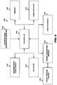
- FIG. 6is a block diagram of a control system according to an embodiment
- FIGS. 7A-Bdepict a fiber array according to an embodiment
- FIG. 8depicts a multiplexing system according to an embodiment
- FIGS. 9A-Cdepict a fiber array according to an embodiment
- FIG. 10depicts a control algorithm according to an embodiment
- FIG. 11depicts a first energizing mode
- FIGS. 12A-Bdepict a second energizing mode
- FIGS. 13A-Cdepict a third energizing mode
- FIGS. 14A-Ddepict a fourth energizing mode.
- FIGS. 1 and 2depict the working or distal ends of various known prior art laser catheters having plural optical fibers 324 embedded therein.
- FIG. 1shows a flexible catheter 100 comprising a catheter lumen 104 to receive an implanted lead or guide wire (not shown) and plural laser emitters 108 positioned around the periphery or diameter of the catheter lumen 104 .
- FIG. 2shows a flexible catheter 200 comprising plural laser emitters 108 packed into the distal end of the catheter.
- the number of rows of optical fibers and emitters located in the catheter and/or located concentrically around the lumen and the number of optical fibers and emitters in each rowcan vary by application and are not limited to the depicted configurations.
- the primary difference between the catheters in FIGS. 1 and 2is the absence of a catheter lumen 104 in the catheter of FIG. 2 .
- a laser ablation catheter 300is positioned in a body lumen 304 , such as a blood vessel, to remove a complete or partial occlusion 308 .
- a guide wire 312passes through the body lumen 304 and occlusion 308 on the one hand and the catheter lumen 316 formed by a substantially cylindrical inner catheter surface 320 on the other to guide the catheter to the occlusion 308 .
- Laser emitters 108are positioned at the distal end of the catheter to ablate the occlusion.
- Optical fiber 324connects a corresponding emitter to the laser via the proximal end or coupler ( FIG. 8 ).
- FIG. 8depicts a laser assembly 800 including a laser 804 , such as a low-temperature excimer laser operating in the ultraviolet spectrum at around 308 nm, a lens assembly 824 (which includes one or more lenses and/or filters), a fiber selector 808 to controllably and selectively energize fibers 108 , a coupler 812 to couple to a proximal end of the laser catheter 300 , and plural optical channels, each channel being represented by a corresponding first, second, third, . . . nth optic fiber set 818 a - n .
- the laser 804emits laser energy or beam 828 , which is directed by the laser assembly 800 to the fiber selector 808 .
- the fiber selector 808directs the laser energy 828 , through the coupler 812 , and onto a selected one of the first, second, third, . . . nth optic fiber set 818 a - n .
- the laser 804can be the same for both treatment and diagnostic laser pulses or different lasers may be employed. When compared to treatment laser pulses, diagnostic laser pulses use lower power.
- FIG. 6depicts a control system 600 according to an embodiment.
- the control system 600includes a controller 604 (which is typically a microprocessor) in signal and electrical communication with a memory 608 , laser circuitry 612 to operate the laser 804 , a user interface 616 to receive commands from and provide queries, target tissue or other endovascular structure information, and other feedback to a user, a target acquisition module 620 to determine target tissue or other endovascular structure location and/or characterization information, a detector 624 to select an optical channel from among plural optical channels for energization, scanner drive electronics 628 to operate the fiber selector 808 for energizing selected optical channels, and an optional catheter size information receiver 632 to receive information regarding the total fiber active area at the distal tip of the catheter.
- a controller 604which is typically a microprocessor
- laser circuitry 612to operate the laser 804
- a user interface 616to receive commands from and provide queries, target tissue or other endovascular structure information, and other feedback to a user
- the controller 604can use target tissue or other endovascular structure location and other imaging or diagnostic information, target tissue or other endovascular structure characterization information (such as tissue density, type, location, and configuration) and/or target tissue or other endovascular structure proximity to other non-target tissue structures, such as blood vessel walls, and total fiber active area at the distal end or tip to select not only laser parameters (such as, for each selected optical channel, fluence, energy density value, intensity, an active area, a maximum allowable fluence, a minimum allowable fluence, repetition rate (e.g., lasing on/off time), and lasing train time) but also the number of optical channels, the fiber active area for each optical channel, the fiber configuration for each optical channel, the specific optical channels to energize for target tissue ablation, and the sequence for energizing the selected channels.
- target tissue or other endovascular structure characterization informationsuch as tissue density, type, location, and configuration
- target tissue or other endovascular structure proximity to other non-target tissue structuressuch as blood vessel walls
- the memory 608can be any computer readable medium and stores, for a current catheterization procedure, a variety of information, including target tissue or other endovascular structure location, characterization information, target tissue or other endovascular structure proximity to non-target tissue structures and other imaging information, laser parameters, optical channel number and configuration, optical channel energizing sequence or ordering, patient information, total fiber active area of the distal end or tip, timestamps, and the like. It can also store various look up tables to enable the controller 604 to configure the optical channels for a currently connected catheter based on the total fiber active area of the catheter. Thus, different models or types or configurations of catheters having different total fiber active areas can have different numbers and configurations of optical channels.
- Laser circuitry 612enables operation of the laser by the controller 604 in response to user commands received by the user interface 616 .
- the laser circuitry 612is conventional.
- the user interface 616can be any audio, video, and/or tactile interface, such as a keyboard, display, microphone, and the like.
- the target acquisition module 620acquires imaging information via a target imaging (and/or diagnostic) module 636 (hereinafter referred to as target imaging module 636 ).
- the imaging informationrelates not only to the structure of the target tissue or other endovascular structure, such as an occlusion, unwanted tissue growth in proximity to a surgically implanted structure, and the like but also to non-target tissue structures in proximity to the target tissue structure.
- the target imaging module 636can be any suitable imaging device, such as, but not limited to, laser induced fluorescence spectroscopy, optical coherence reflectometry, optical coherence tomography, and Raman spectroscopy.
- the imaging informationcan be a two, three, or four dimensional representation of the imaged tissue structures.
- the detector 624operatively engages the fiber selector 808 to determine a current optical channel positioned for energizing by the laser and/or a position of a selected optical channel relative to a desired position for the optical channel.
- the detector 624can be any suitable configuration, whether a mechanical, optical, electrical, and/or electromagnetic device for tracking movement and/or a current position of the fiber selector 808 . It can also be configured as one or more proximity sensors to fire the laser at the precise time that the beam is incident on the target fibers or bundles (or set) of fibers.
- the scanner drive electronics 628one or more of controllably directs the laser beam in a desired orientation and/or controls movement of the fiber selector 808 .
- An example of the former configurationis described in U.S. Pat. No. 5,400,428 to Grace, which is incorporated herein by this reference.
- Gracediscloses a dielectric mirror mounted on a galvanometer scanner that is moved to cause successive laser pulses to irradiate different optical channels, thereby enabling each fiber to receive radiation having sufficient fluence while reducing the energy per pulse (or the cw equivalent). Examples of the latter configuration are discussed below.
- the catheter size information receiver 632can be any configuration. For example, it can be based on a lookup table using an identifier of the catheter.
- the identifiercan be provided by a pin sequence or configuration on the proximal end of the catheter.
- the sequence and/or configuration of pinsis mounted to the proximal end of the catheter.
- the pin arrangement or sequenceactuates switches in the catheter's coupler to generate a signal, which is forwarded to the controller 604 .
- the controller 604can identify the type and/or model of the catheter and therefore the appropriate catheter specifications, requirements, and other operating information.
- Each type and/or model of catheterhas a unique pin sequence to actuate different switches for generating different signals.
- the fiber selector 808is shown as being distal to the coupler, it may be positioned within or proximal to the coupler, depending on the application.
- FIG. 4a first fiber selector configuration is depicted. While FIG. 4 and other figures depict the optical fibers as a linear array for purposes of simplicity, it is to be understood that other fiber arrangements can be employed, particularly fibers oriented in a three dimensional array.
- the fiber selector 808comprises a rotating wedge optical member 400 positioned in the optical path 404 of the laser beam 408 to redirect, by optical refraction, the laser beam onto one or more selected fibers 324 , with the optical fiber(s) irradiated at any one time corresponding to an optical channel and optical fiber(s) irradiated at different times corresponding to different optical channels.
- a wedge prismcan be uncoated or coated with an anti-reflection coating and can deviate an angle of an incident beam. Typically, the wedge prism deviates the angle of the laser beam by an amount ranging from about 70 to about 20 degrees.
- the wedge optical member 400typically has a thickness that is dependent upon the desired beam deviation, which is a also a function of the size of the coupler. This causes the laser beam 408 to be diverted at an angle ⁇ 428 relative to the optical path 404 along a diverging optical path.
- the motor-driven rotation of the optical membercan be at fixed and/or variable speeds.
- plural wedge optical memberscan be used to redirect the laser beam.
- two wedge prismscan be used as an anamorphic pair to steer the beam anywhere within a circle described by the full angle 40 , where ⁇ is the deviation from a single prism. This beam steering is accomplished by rotating the two wedge prisms independently of each other.
- the position of the wedge optical member 400can be determined by the detector 624 based upon, for example, radiation reflected by a locating member 432 , which rotates simultaneously and in an amount related to rotation of the wedge optical member 400 .
- the locating member 432can be encoded with encoding elements that reflect light uniquely or substantially uniquely for any position around the circumference of the locating member 432 .
- To produce the unique light reflectancecan be the result of the encoding elements being differently sized, spaced, and/or colored.
- An example of such encoding elementsis a bar code.
- the detector 624emits light onto the locating member, detects the reflected spectra, and maps the reflected spectra against a lookup table that indexes each absolute and/or relative position around the locating member 432 against a corresponding set of reflected spectra. Based on the comparison, a locating signal is generated and sent to the controller 604 , which then instructs a subcontroller (not shown), which further instructs the motor (not shown) to rotate the wedge optical member 400 a selected angle to align the selected optical channel with the redirected laser beam 408 .
- the lasercan be fired at the time the beam is deflected to the position to couple into the desired fiber or bundle of fibers. While tracking the position of the wedge optical member 400 is discussed with reference to an optical encoder, other types of encoders may be employed, such as mechanical, electrical, and/or electromagnetic position tracking devices.
- FIG. 5a second fiber selector configuration is depicted.
- the fiber selector 808comprises a rotating parallel-faced optical member 500 positioned in the optical path 404 of the laser beam 408 to redirect, by optical refraction, the laser beam onto one or more selected fibers 324 .
- the parallel-faced optical member 500comprises opposing parallel faces 504 and 508 and is inclined relative to the optical path 404 at an angle ⁇ 512 sufficient to deviate the laser beam 408 from the optical path 408 by an angle ranging from about 70 to about 20 degrees.
- the optical member 500typically has a thickness that is dependent upon the desired beam deviation, which is a also a function of the size of the coupler.
- the inclined parallel surfaces 504 and 512cause the laser beam 408 to be diverted and offset relative to and substantially parallel to the optical path 404 .
- the direction of rotationis a matter of design choice.
- optical membersmay be used.
- a faceted optical memberknown as an axicon
- a faceted optical elementis employed.
- FIGS. 7A-Ba third fiber selector configuration is depicted. This configuration is further discussed in U.S. Pat. No. 5,400,428 referenced above.
- a grooved fiber holder 700holds two equally sized bundles of fibers 818 a,b , each bundle corresponding to a different optical channel. Bundles 818 a,b are centered upon the same linear transverse axis 704 .
- the laser beamis focused so that the first incident beam pulse irradiates all of fiber bundle 818 b ( FIG. 7A ), which is half of the total fibers. Either the beam or the fibers are then shifted so that next pulse of the laser beam is focused on bundle 818 a ( FIG. 7B ).
- the grooved fiber holder 700can be translated along the linear transverse axis 704 by displacing the holder 700 laterally in a carrier member 708 , such as energizing a piezoelectric stack or a motor.
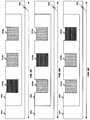
- FIGS. 9A-Ca fourth fiber selector configuration is depicted.
- FIGS. 9A-Cillustrate three bundles of optical fibers 818 a , 818 b and 818 c , each bundle corresponding to a different optical channel.
- Each bundle of fibers 818 a , 818 b and 818 ccontains 1 ⁇ 3 of the total number of fibers.
- the optical fiber bundlesare disposed in a grooved fiber holder 900 that moves laterally within a holder 904 as discussed above.
- First scan positionFIG. 9A
- a second scan positionFIG.
- the beam and fibersare moved relative to one another to irradiate the second fiber bundle 818 b .
- the next laser pulseis directed at the third bundle of optical fibers 818 c .
- the fiber bundlesare disposed in a linear manner along the same transverse axis 320 to provide for linear scanning.
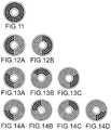
- the distal end or tip of the catheterenergizes all or part of the laser emitters 108 as shown in FIGS. 11, 12A -B, 13 A-C, and 14 A-D.
- the portion of the laser emitters 108 energized, or the number of optical channels employeddepend on one or more of target tissue or other endovascular structure location, target tissue or other endovascular structure characterization information (such as tissue density, type, location, and configuration), current location and/or orientation of the distal tip of the catheter, and/or target tissue or other endovascular structure proximity to other non-target tissue structures, and total fiber active area at the distal end or tip.
- darkened laser emittersrefer to those being energized while undarkened laser emitters refer to those not being energized.
- FIG. 11depicts a first operating mode in which all of the laser emitters 108 in the distal tip of the catheter are energized simultaneously.
- FIGS. 12A-Bdepict a second operating mode for a 2-way multiplexing configuration in which one-half of the laser emitters 108 are energized simultaneously at a first time and the other half of the laser emitters 108 are energized simultaneously at a second (different) time.
- This operating modecan be produced by any of the first, second, and third fiber selector configurations.
- FIGS. 13A-Cdepict a third operating mode for a 3-way multiplexing configuration in which a first one-third of the laser emitters 108 is energized simultaneously at a first time, a second one-third of the laser emitters 108 is energized simultaneously at a second time, and a third one-third of the laser emitters 108 is energized simultaneously at a third time.
- the first, second, and third timesare different.
- This operating modecan be produced by any of the first, second, and fourth fiber selector configurations.
- FIGS. 14A-Ddepict a fourth operating mode for a 4-way multiplexing configuration in which a first one-quarter of the laser emitters 108 is energized simultaneously at a first time, a second one-quarter of the laser emitters 108 is energized simultaneously at a second time, a third one-quarter of the laser emitters 108 is energized simultaneously at a third time, and a fourth one-quarter of the laser emitters 108 is energized simultaneously at a fourth time.
- the first, second, third, and fourth timesare different.
- This operating modecan be produced by any of the first and second fiber selector configurations.
- multiplexingmay be performed up to N ways, with N being a whole number. Multiplexing is not limited to 2, 3, and 4 ways as shown in the above figures.
- the geometrical pattern of laser emitters 108 energizedcan be different from those shown.
- the laser emitters 108can be energized along an arc, be randomly distributed, and/or be uniformly or nonuniformly distributed around the circumference of the distal tip of the catheter.
- the operationcommences in step 1000 in which the controller 604 detects a stimulus.
- the stimuluscan be, for example, a command received from an operator, such as a physician, via the user interface 616 .
- the controller 604determines a total fiber active area of the catheter currently coupled to the coupler 812 .
- the controller 604selects a number of optical channels based on the determined total fiber active area. As noted, this can be done using a lookup table. In other configurations, the controller 604 can use other information, particularly imaging information (including target tissue or other endovascular structure location, target tissue or other endovascular structure characterization information (such as tissue density, type, location, and configuration), current location and/or orientation of the distal tip of the catheter, and/or target tissue or other endovascular structure proximity to other non-target tissue structures) received from the target acquisition module 620 in addition to or lieu of the total fiber active area in selecting the number of optical channels. In that event, step 1008 would follow step 1012 .
- imaging informationincluding target tissue or other endovascular structure location, target tissue or other endovascular structure characterization information (such as tissue density, type, location, and configuration), current location and/or orientation of the distal tip of the catheter, and/or target tissue or other endovascular structure proximity to other non-target tissue structures
- the controller 604selects one or more of a fiber active area for each optical channel, a number of optical channels, a configuration of fibers in an optical channel, an optical channel to be irradiated, and an ordering of optical channel irradiation based on one or more of total fiber active area of the laser catheter, imaging information regarding the target and/or non-target endovascular structure(s), target endovascular structure characterization information, and current location and/or orientation of a distal tip of the laser catheter.
- the controller 604receives target acquisition information from the target acquisition module 620 and indirectly from the target imaging module 636 .
- the target acquisition informationis typically imaging information.
- additional wavelengths of lightare launched down the fibers and through the laser emitters in the catheter and returned or reflected light analyzed to determine reflectivity and absorption data. This can be used to determine target and/or non-target tissue or other endovascular structure location, type, and/or contact area (area of contact between the distal tip and structure of the target tissue or other endovascular structure).
- step 1016the controller 604 selects which of the optical channels to energize to ablate the target tissue or other endovascular structure. This can be determined based upon any or all of the information referenced in the prior paragraph and/or user input.
- step 1020the controller 604 determines an energization sequence.
- the sequencegoverns which optical channels are energized and in what order and times. This can be determined based upon any or all of the information referenced previously including imaging information and user input.
- step 1024the controller 604 initiates optical channel energization in accordance with the determined energization sequence.
- exemplary aspects, embodiments, and/or configurations illustrated hereinshow the various components of the system collocated, certain components of the system can be located remotely, at distant portions of a distributed network, such as a LAN and/or the Internet, or within a dedicated system.
- a distributed networksuch as a LAN and/or the Internet
- the components of the systemcan be combined in to one or more devices, such as a base unit, or collocated on a particular node of a distributed network.
- the various links connecting the elementscan be wired or wireless links, or any combination thereof, or any other known or later developed element(s) that is capable of supplying and/or communicating data to and from the connected elements.
- These wired or wireless linkscan also be secure links and may be capable of communicating encrypted information.
- Transmission media used as linkscan be any suitable carrier for electrical signals, including coaxial cables, copper wire and fiber optics, and may take the form of acoustic or light waves, such as those generated during radio-wave and infra-red data communications.
- the systems and methods of this disclosurecan be implemented in conjunction with a special purpose computer, a programmed microprocessor or microcontroller and peripheral integrated circuit element(s), an ASIC or other integrated circuit, a digital signal processor, a hard-wired electronic or logic circuit such as discrete element circuit, a programmable logic device or gate array such as PLD, PLA, FPGA, PAL, special purpose computer, any comparable means, or the like.
- a special purpose computera programmed microprocessor or microcontroller and peripheral integrated circuit element(s), an ASIC or other integrated circuit, a digital signal processor, a hard-wired electronic or logic circuit such as discrete element circuit, a programmable logic device or gate array such as PLD, PLA, FPGA, PAL, special purpose computer, any comparable means, or the like.
- any device(s) or means capable of implementing the methodology illustrated hereincan be used to implement the various aspects of this disclosure.
- Exemplary hardwarethat can be used for the disclosed embodiments, configurations and aspects includes computers, handheld devices, telephones (e.g., cellular, Internet enabled, digital, analog, hybrids, and others), and other hardware known in the art. Some of these devices include processors (e.g., a single or multiple microprocessors), memory, nonvolatile storage, input devices, and output devices.
- processorse.g., a single or multiple microprocessors
- memorye.g., a single or multiple microprocessors
- nonvolatile storagee.g., a single or multiple microprocessors
- input devicese.g., input devices
- output devicese.g., input devices, and output devices.
- alternative software implementationsincluding, but not limited to, distributed processing or component/object distributed processing, parallel processing, or virtual machine processing can also be constructed to implement the methods described herein.
- the disclosed methodsmay be readily implemented in conjunction with software using object or object-oriented software development environments that provide portable source code that can be used on a variety of computer or workstation platforms.
- the disclosed systemmay be implemented partially or fully in hardware using standard logic circuits or VLSI design. Whether software or hardware is used to implement the systems in accordance with this disclosure is dependent on the speed and/or efficiency requirements of the system, the particular function, and the particular software or hardware systems or microprocessor or microcomputer systems being utilized.
- the disclosed methodsmay be partially implemented in software that can be stored on a storage medium, executed on programmed general-purpose computer with the cooperation of a controller and memory, a special purpose computer, a microprocessor, or the like.
- the systems and methods of this disclosurecan be implemented as program embedded on personal computer such as an applet, JAVA® or CGI script, as a resource residing on a server or computer workstation, as a routine embedded in a dedicated measurement system, system component, or the like.
- the systemcan also be implemented by physically incorporating the system and/or method into a software and/or hardware system.
- the present disclosurein various aspects, embodiments, and/or configurations, includes components, methods, processes, systems and/or apparatus substantially as depicted and described herein, including various aspects, embodiments, configurations embodiments, subcombinations, and/or subsets thereof.
- the present disclosurein various aspects, embodiments, and/or configurations, includes providing devices and processes in the absence of items not depicted and/or described herein or in various aspects, embodiments, and/or configurations hereof, including in the absence of such items as may have been used in previous devices or processes, e.g., for improving performance, achieving ease and ⁇ or reducing cost of implementation.
Landscapes
- Health & Medical Sciences (AREA)
- Life Sciences & Earth Sciences (AREA)
- Physics & Mathematics (AREA)
- Surgery (AREA)
- Public Health (AREA)
- Animal Behavior & Ethology (AREA)
- Veterinary Medicine (AREA)
- Engineering & Computer Science (AREA)
- Biomedical Technology (AREA)
- Heart & Thoracic Surgery (AREA)
- Medical Informatics (AREA)
- Molecular Biology (AREA)
- General Health & Medical Sciences (AREA)
- Biophysics (AREA)
- Pathology (AREA)
- Nuclear Medicine, Radiotherapy & Molecular Imaging (AREA)
- Optics & Photonics (AREA)
- Electromagnetism (AREA)
- Otolaryngology (AREA)
- Radiology & Medical Imaging (AREA)
- Laser Surgery Devices (AREA)
- Spectroscopy & Molecular Physics (AREA)
Abstract
Description
Claims (9)
Priority Applications (3)
| Application Number | Priority Date | Filing Date | Title |
|---|---|---|---|
| US13/826,053US10758308B2 (en) | 2013-03-14 | 2013-03-14 | Controller to select optical channel parameters in a catheter |
| PCT/US2014/019283WO2014158688A1 (en) | 2013-03-14 | 2014-02-28 | Smart multiplexed medical laser system |
| EP14773432.1AEP2967751B1 (en) | 2013-03-14 | 2014-02-28 | Smart multiplexed medical laser system |
Applications Claiming Priority (1)
| Application Number | Priority Date | Filing Date | Title |
|---|---|---|---|
| US13/826,053US10758308B2 (en) | 2013-03-14 | 2013-03-14 | Controller to select optical channel parameters in a catheter |
Publications (2)
| Publication Number | Publication Date |
|---|---|
| US20140276690A1 US20140276690A1 (en) | 2014-09-18 |
| US10758308B2true US10758308B2 (en) | 2020-09-01 |
Family
ID=51530870
Family Applications (1)
| Application Number | Title | Priority Date | Filing Date |
|---|---|---|---|
| US13/826,053Active2038-10-28US10758308B2 (en) | 2013-03-14 | 2013-03-14 | Controller to select optical channel parameters in a catheter |
Country Status (1)
| Country | Link |
|---|---|
| US (1) | US10758308B2 (en) |
Families Citing this family (34)
| Publication number | Priority date | Publication date | Assignee | Title |
|---|---|---|---|---|
| US8545488B2 (en) | 2004-09-17 | 2013-10-01 | The Spectranetics Corporation | Cardiovascular imaging system |
| US9068952B2 (en)* | 2009-09-02 | 2015-06-30 | Kla-Tencor Corporation | Method and apparatus for producing and measuring dynamically focussed, steered, and shaped oblique laser illumination for spinning wafer inspection system |
| US9623211B2 (en) | 2013-03-13 | 2017-04-18 | The Spectranetics Corporation | Catheter movement control |
| US11642169B2 (en)* | 2013-03-14 | 2023-05-09 | The Spectranetics Corporation | Smart multiplexed medical laser system |
| US9757200B2 (en) | 2013-03-14 | 2017-09-12 | The Spectranetics Corporation | Intelligent catheter |
| US10835313B2 (en)* | 2014-01-30 | 2020-11-17 | Medlumics S.L. | Radiofrequency ablation catheter with optical tissue evaluation |
| US10987168B2 (en) | 2014-05-29 | 2021-04-27 | Spectranetics Llc | System and method for coordinated laser delivery and imaging |
| JP2018503485A (en)* | 2014-12-29 | 2018-02-08 | アイ シン アジョイ | Arterial treatment system and method |
| US10646118B2 (en) | 2014-12-30 | 2020-05-12 | Regents Of The University Of Minnesota | Laser catheter with use of reflected light to determine material type in vascular system |
| US10646275B2 (en) | 2014-12-30 | 2020-05-12 | Regents Of The University Of Minnesota | Laser catheter with use of determined material type in vascular system in ablation of material |
| US10646274B2 (en) | 2014-12-30 | 2020-05-12 | Regents Of The University Of Minnesota | Laser catheter with use of reflected light and force indication to determine material type in vascular system |
| WO2017154005A1 (en)* | 2016-03-10 | 2017-09-14 | Biop - Medical Ltd | Device for diagnosing a tissue |
| US11020563B2 (en) | 2016-07-14 | 2021-06-01 | C. R. Bard, Inc. | Automated catheter-to-vessel size comparison tool and related methods |
| US11253317B2 (en) | 2017-03-20 | 2022-02-22 | Precise Light Surgical, Inc. | Soft tissue selective ablation surgical systems |
| US11759166B2 (en) | 2019-09-20 | 2023-09-19 | Bard Access Systems, Inc. | Automatic vessel detection tools and methods |
| US11877810B2 (en) | 2020-07-21 | 2024-01-23 | Bard Access Systems, Inc. | System, method and apparatus for magnetic tracking of ultrasound probe and generation of 3D visualization thereof |
| EP4185209A1 (en) | 2020-08-04 | 2023-05-31 | Bard Access Systems, Inc. | System and method for optimized medical component insertion monitoring and imaging enhancement |
| WO2022035760A1 (en) | 2020-08-10 | 2022-02-17 | Bard Access Systems, Inc. | System and method for generating vessel representations in mixed reality/virtual reality |
| US11890139B2 (en) | 2020-09-03 | 2024-02-06 | Bard Access Systems, Inc. | Portable ultrasound systems |
| US11992363B2 (en) | 2020-09-08 | 2024-05-28 | Bard Access Systems, Inc. | Dynamically adjusting ultrasound-imaging systems and methods thereof |
| CN216257185U (en) | 2020-09-10 | 2022-04-12 | 巴德阿克塞斯系统股份有限公司 | Ultrasound Probes and Ultrasound Systems |
| WO2022067101A1 (en) | 2020-09-25 | 2022-03-31 | Bard Access Systems, Inc. | Minimum catheter length tool |
| WO2022072727A2 (en) | 2020-10-02 | 2022-04-07 | Bard Access Systems, Inc. | Ultrasound systems and methods for sustained spatial attention |
| EP4228516A1 (en) | 2020-10-15 | 2023-08-23 | Bard Access Systems, Inc. | Ultrasound imaging system for generation of a three-dimensional ultrasound image |
| CN216933458U (en) | 2020-11-24 | 2022-07-12 | 巴德阿克塞斯系统股份有限公司 | Object recognition and needle guidance system |
| CN114569155A (en) | 2020-12-01 | 2022-06-03 | 巴德阿克塞斯系统股份有限公司 | Ultrasound imaging system and method for obtaining ultrasound image by the same |
| CN114569156A (en) | 2020-12-01 | 2022-06-03 | 巴德阿克塞斯系统股份有限公司 | Ultrasound imaging system and method for identifying one or more of a plurality of blood vessels |
| EP4258997A1 (en) | 2020-12-14 | 2023-10-18 | Bard Access Systems, Inc. | Securement of hands-free ultrasound probe |
| CN217960146U (en) | 2021-04-15 | 2022-12-06 | 巴德阿克塞斯系统股份有限公司 | Ultrasound imaging system |
| CN116058873A (en) | 2021-11-03 | 2023-05-05 | 巴德阿克塞斯系统股份有限公司 | Interoperation optimization function through Doppler and image-based vessel discrimination |
| CN114431955B (en)* | 2022-02-14 | 2024-06-14 | 清华大学 | Ultra-fast laser galvanometer scanning coupling method |
| US12433567B2 (en) | 2022-03-16 | 2025-10-07 | Bard Access Systems, Inc. | Ultrasound imaging system |
| US12102481B2 (en) | 2022-06-03 | 2024-10-01 | Bard Access Systems, Inc. | Ultrasound probe with smart accessory |
| US12137989B2 (en) | 2022-07-08 | 2024-11-12 | Bard Access Systems, Inc. | Systems and methods for intelligent ultrasound probe guidance |
Citations (170)
| Publication number | Priority date | Publication date | Assignee | Title |
|---|---|---|---|---|
| US4053845A (en) | 1967-03-06 | 1977-10-11 | Gordon Gould | Optically pumped laser amplifiers |
| US4641912A (en) | 1984-12-07 | 1987-02-10 | Tsvi Goldenberg | Excimer laser delivery system, angioscope and angioplasty system incorporating the delivery system and angioscope |
| US4669465A (en) | 1984-12-10 | 1987-06-02 | Gv Medical, Inc. | Laser catheter control and connecting apparatus |
| US4686979A (en) | 1984-01-09 | 1987-08-18 | The United States Of America As Represented By The United States Department Of Energy | Excimer laser phototherapy for the dissolution of abnormal growth |
| US4732448A (en) | 1984-12-07 | 1988-03-22 | Advanced Interventional Systems, Inc. | Delivery system for high-energy pulsed ultraviolet laser light |
| US4747405A (en) | 1984-03-01 | 1988-05-31 | Vaser, Inc. | Angioplasty catheter |
| US4769005A (en) | 1987-08-06 | 1988-09-06 | Robert Ginsburg | Selective catheter guide |
| US4784132A (en) | 1983-03-25 | 1988-11-15 | Fox Kenneth R | Method of and apparatus for laser treatment of body lumens |
| US4788975A (en) | 1987-11-05 | 1988-12-06 | Medilase, Inc. | Control system and method for improved laser angioplasty |
| US4799754A (en) | 1985-09-25 | 1989-01-24 | Advanced Interventional Systems, Inc. | Delivery system for high-energy pulsed ultraviolet laser light |
| US4807620A (en) | 1987-05-22 | 1989-02-28 | Advanced Interventional Systems, Inc. | Apparatus for thermal angioplasty |
| GB2208807A (en) | 1985-05-22 | 1989-04-19 | Bard Inc C R | Laser catheter |
| US4830460A (en) | 1987-05-19 | 1989-05-16 | Advanced Interventional Systems, Inc. | Guidance system and method for delivery system for high-energy pulsed ultraviolet laser light |
| US4844062A (en) | 1987-10-23 | 1989-07-04 | Spectranetics Corporation | Rotating fiberoptic laser catheter assembly with eccentric lumen |
| US4848336A (en) | 1981-12-11 | 1989-07-18 | Fox Kenneth R | Apparatus for laser treatment of body lumens |
| US4850686A (en) | 1987-02-06 | 1989-07-25 | Asahi Kogaku Kogyo K.K. | Apparatus for adjusting light beam direction |
| US4913142A (en)* | 1985-03-22 | 1990-04-03 | Massachusetts Institute Of Technology | Catheter for laser angiosurgery |
| US4919508A (en)* | 1988-08-04 | 1990-04-24 | The Spectranetics Corporation | Fiberoptic coupler |
| US4925265A (en) | 1988-04-11 | 1990-05-15 | Xintec Corporation | Apparatus for directing a laser beam into optical fibers |
| US4924863A (en) | 1988-05-04 | 1990-05-15 | Mmtc, Inc. | Angioplastic method for removing plaque from a vas |
| US5016964A (en) | 1989-10-04 | 1991-05-21 | Spectranetics Corporation | Optical fiber coupler with linear input |
| US5024234A (en) | 1989-10-17 | 1991-06-18 | Cardiovascular Imaging Systems, Inc. | Ultrasonic imaging catheter with guidewire channel |
| US5026366A (en) | 1984-03-01 | 1991-06-25 | Cardiovascular Laser Systems, Inc. | Angioplasty catheter and method of use thereof |
| US5029588A (en) | 1989-06-15 | 1991-07-09 | Cardiovascular Imaging Systems, Inc. | Laser catheter with imaging capability |
| US5034010A (en) | 1985-03-22 | 1991-07-23 | Massachusetts Institute Of Technology | Optical shield for a laser catheter |
| US5040548A (en) | 1989-06-01 | 1991-08-20 | Yock Paul G | Angioplasty mehtod |
| US5041108A (en) | 1981-12-11 | 1991-08-20 | Pillco Limited Partnership | Method for laser treatment of body lumens |
| US5047952A (en) | 1988-10-14 | 1991-09-10 | The Board Of Trustee Of The Leland Stanford Junior University | Communication system for deaf, deaf-blind, or non-vocal individuals using instrumented glove |
| US5154680A (en) | 1990-03-27 | 1992-10-13 | Rutgers University | Pressure waveform monitor |
| US5165897A (en) | 1990-08-10 | 1992-11-24 | Tini Alloy Company | Programmable tactile stimulator array system and method of operation |
| US5188632A (en) | 1984-12-07 | 1993-02-23 | Advanced Interventional Systems, Inc. | Guidance and delivery system for high-energy pulsed laser light |
| US5207672A (en) | 1989-05-03 | 1993-05-04 | Intra-Sonix, Inc. | Instrument and method for intraluminally relieving stenosis |
| US5217454A (en) | 1991-08-01 | 1993-06-08 | Angiolaz, Incorporated | Laser delivery catheter |
| US5243546A (en) | 1991-01-10 | 1993-09-07 | Ashland Oil, Inc. | Spectroscopic instrument calibration |
| US5250045A (en) | 1991-06-11 | 1993-10-05 | The Spectranetics Corporation | Optical fiber catheter with spaced optical fiber |
| US5263953A (en) | 1991-12-31 | 1993-11-23 | Spine-Tech, Inc. | Apparatus and system for fusing bone joints |
| US5267341A (en) | 1991-10-30 | 1993-11-30 | Baxter International Inc. | Fluid catheter with aqueous fluid core and method of use |
| US5300085A (en) | 1986-04-15 | 1994-04-05 | Advanced Cardiovascular Systems, Inc. | Angioplasty apparatus facilitating rapid exchanges and method |
| US5304171A (en) | 1990-10-18 | 1994-04-19 | Gregory Kenton W | Catheter devices and methods for delivering |
| US5318032A (en) | 1992-02-05 | 1994-06-07 | Devices For Vascular Intervention | Guiding catheter having soft tip |
| US5350377A (en) | 1992-10-26 | 1994-09-27 | Ultrasonic Sensing & Monitoring Systems, Inc. | Medical catheter using optical fibers that transmit both laser energy and ultrasonic imaging signals |
| US5350375A (en) | 1993-03-15 | 1994-09-27 | Yale University | Methods for laser induced fluorescence intensity feedback control during laser angioplasty |
| US5352197A (en) | 1992-03-18 | 1994-10-04 | The Spectranetics Corporation | Turn limiter for a catheter with twistable tip |
| US5377683A (en) | 1989-07-31 | 1995-01-03 | Barken; Israel | Ultrasound-laser surgery apparatus and method |
| US5400428A (en) | 1992-05-13 | 1995-03-21 | Spectranetics Corporation | Method and apparatus for linearly scanning energy over an optical fiber array and coupler for coupling energy to the optical fiber array |
| US5415653A (en) | 1992-08-26 | 1995-05-16 | Advanced Interventional Systems, Inc. | Optical catheter with stranded fibers |
| US5423740A (en) | 1991-07-22 | 1995-06-13 | Theratek International, Inc. | Controller for intravascular catheter system |
| US5425355A (en) | 1991-01-28 | 1995-06-20 | Laserscope | Energy discharging surgical probe and surgical process having distal energy application without concomitant proximal movement |
| US5429604A (en) | 1992-03-18 | 1995-07-04 | Spectranetics Corporation | Fiber optic catheter with twistable tip |
| US5429617A (en) | 1993-12-13 | 1995-07-04 | The Spectranetics Corporation | Radiopaque tip marker for alignment of a catheter within a body |
| US5440664A (en) | 1994-01-13 | 1995-08-08 | Rutgers, The State University Of New Jersey | Coherent, flexible, coated-bore hollow-fiber waveguide |
| US5456680A (en) | 1993-09-14 | 1995-10-10 | Spectranetics Corp | Fiber optic catheter with shortened guide wire lumen |
| US5464395A (en) | 1994-04-05 | 1995-11-07 | Faxon; David P. | Catheter for delivering therapeutic and/or diagnostic agents to the tissue surrounding a bodily passageway |
| US5470330A (en) | 1984-12-07 | 1995-11-28 | Advanced Interventional Systems, Inc. | Guidance and delivery system for high-energy pulsed laser light |
| US5483080A (en) | 1992-09-18 | 1996-01-09 | Tam; Lisa A. | Method and device for measuring and controlling cell density in microbiological culture |
| US5484433A (en) | 1993-12-30 | 1996-01-16 | The Spectranetics Corporation | Tissue ablating device having a deflectable ablation area and method of using same |
| US5492131A (en) | 1994-09-06 | 1996-02-20 | Guided Medical Systems, Inc. | Servo-catheter |
| US5514128A (en) | 1992-08-18 | 1996-05-07 | Spectranetics Corporation | Fiber optic guide wire and support catheter therefor |
| US5536242A (en) | 1994-07-01 | 1996-07-16 | Scimed Life Systems, Inc. | Intravascular device utilizing fluid to extract occlusive material |
| EP0211984B2 (en) | 1985-08-19 | 1996-09-11 | Inc. Vpl Research | Computer data entry and manipulation apparatus |
| US5571151A (en) | 1994-10-25 | 1996-11-05 | Gregory; Kenton W. | Method for contemporaneous application of laser energy and localized pharmacologic therapy |
| US5573531A (en) | 1994-06-20 | 1996-11-12 | Gregory; Kenton W. | Fluid core laser angioscope |
| US5623940A (en) | 1994-08-02 | 1997-04-29 | S.L.T. Japan Co., Ltd. | Catheter apparatus with a sensor |
| US5649923A (en) | 1988-10-24 | 1997-07-22 | The General Hospital Corporation | Catheter devices for delivering laser energy |
| US5657760A (en) | 1994-05-03 | 1997-08-19 | Board Of Regents, The University Of Texas System | Apparatus and method for noninvasive doppler ultrasound-guided real-time control of tissue damage in thermal therapy |
| US5722972A (en) | 1993-08-12 | 1998-03-03 | Power; John A. | Method and apparatus for ablation of atherosclerotic blockage |
| WO1998019614A1 (en) | 1996-11-08 | 1998-05-14 | Fogarty Thomas J | Transvascular tmr device and method |
| US5755714A (en) | 1996-09-17 | 1998-05-26 | Eclipse Surgical Technologies, Inc. | Shaped catheter for transmyocardial revascularization |
| US5792118A (en) | 1994-03-07 | 1998-08-11 | Kurth; Paul A. | Permanent catheter with an exterior balloon valve and method of using the same |
| US5800350A (en) | 1993-11-01 | 1998-09-01 | Polartechnics, Limited | Apparatus for tissue type recognition |
| US5803083A (en) | 1995-11-09 | 1998-09-08 | Cordis Corporation | Guiding catheter with ultrasound imaging capability |
| US5807377A (en) | 1996-05-20 | 1998-09-15 | Intuitive Surgical, Inc. | Force-reflecting surgical instrument and positioning mechanism for performing minimally invasive surgery with enhanced dexterity and sensitivity |
| US5817144A (en) | 1994-10-25 | 1998-10-06 | Latis, Inc. | Method for contemporaneous application OF laser energy and localized pharmacologic therapy |
| US5824026A (en) | 1996-06-12 | 1998-10-20 | The Spectranetics Corporation | Catheter for delivery of electric energy and a process for manufacturing same |
| US5830209A (en) | 1992-02-05 | 1998-11-03 | Angeion Corporation | Multi-fiber laser catheter |
| USRE36104E (en) | 1992-10-30 | 1999-02-16 | Cordis Corporation | Dilation catheter with eccentric balloon |
| US5891133A (en) | 1996-03-29 | 1999-04-06 | Eclipse Surgical Technologies, Inc. | Apparatus for laser-assisted intra-coronary transmyocardial revascularization and other applications |
| US5938609A (en) | 1990-05-18 | 1999-08-17 | Cardiovascular Imaging Systems, Inc. | Guidewire with imaging capability |
| US5976124A (en) | 1998-01-05 | 1999-11-02 | Spectranetics Corporation | Phototherapy device and method |
| US5986643A (en) | 1987-03-24 | 1999-11-16 | Sun Microsystems, Inc. | Tactile feedback mechanism for a data processing system |
| US5989243A (en) | 1984-12-07 | 1999-11-23 | Advanced Interventional Systems, Inc. | Excimer laser angioplasty system |
| US6022342A (en) | 1998-06-02 | 2000-02-08 | Mukherjee; Dipankar | Catheter introducer for antegrade and retrograde medical procedures |
| US6033402A (en) | 1998-09-28 | 2000-03-07 | Irvine Biomedical, Inc. | Ablation device for lead extraction and methods thereof |
| US6056743A (en) | 1997-11-04 | 2000-05-02 | Scimed Life Systems, Inc. | Percutaneous myocardial revascularization device and method |
| US6117128A (en) | 1997-04-30 | 2000-09-12 | Kenton W. Gregory | Energy delivery catheter and method for the use thereof |
| WO2000057228A2 (en) | 1999-03-23 | 2000-09-28 | Renishaw Plc | Apparatus for producing and guiding a light beam |
| US6231563B1 (en) | 1996-01-25 | 2001-05-15 | Baxter International Inc. | Directional catheter |
| US20010014805A1 (en) | 1998-12-08 | 2001-08-16 | Fred Burbank | Devices for occlusion of the uterine arteries |
| US6287297B1 (en) | 1999-03-05 | 2001-09-11 | Plc Medical Systems, Inc. | Energy delivery system and method for performing myocardial revascular |
| US6290668B1 (en) | 1998-04-30 | 2001-09-18 | Kenton W. Gregory | Light delivery catheter and methods for the use thereof |
| US6302875B1 (en) | 1996-10-11 | 2001-10-16 | Transvascular, Inc. | Catheters and related devices for forming passageways between blood vessels or other anatomical structures |
| US20020013572A1 (en) | 2000-05-19 | 2002-01-31 | Berlin Michael S. | Delivery system and method of use for the eye |
| US20020026118A1 (en) | 2000-08-18 | 2002-02-28 | Assaf Govari | Three-dimensional reconstruction using ultrasound |
| US6370411B1 (en) | 1998-02-10 | 2002-04-09 | Biosense, Inc. | Catheter calibration |
| US20020045811A1 (en) | 1985-03-22 | 2002-04-18 | Carter Kittrell | Laser ablation process and apparatus |
| US20020072661A1 (en) | 2000-12-13 | 2002-06-13 | Wiesmann William P. | Minimally invasive system for assessment of organ function |
| US6419684B1 (en) | 2000-05-16 | 2002-07-16 | Linvatec Corporation | End-cutting shaver blade for axial resection |
| US20020103459A1 (en) | 2000-12-05 | 2002-08-01 | Sparks Kurt D. | Catheter system for vascular re-entry from a sub-intimal space |
| US20020107445A1 (en) | 1999-03-11 | 2002-08-08 | Assaf Govari | Implantable and insertable passive tags |
| US6432115B1 (en) | 1999-04-05 | 2002-08-13 | Starion Instruments Corporation | Suture welding device |
| US6447525B2 (en) | 1999-08-19 | 2002-09-10 | Fox Hollow Technologies, Inc. | Apparatus and methods for removing material from a body lumen |
| US6447504B1 (en) | 1998-07-02 | 2002-09-10 | Biosense, Inc. | System for treatment of heart tissue using viability map |
| US6458098B1 (en) | 2000-03-17 | 2002-10-01 | Nozomu Kanesaka | Vascular therapy device |
| US20020159685A1 (en) | 2001-04-27 | 2002-10-31 | Cormack Robert H. | 1xN optical fiber switch |
| US20030032936A1 (en) | 2001-08-10 | 2003-02-13 | Lederman Robert J. | Side-exit catheter and method for its use |
| US20030045798A1 (en) | 2001-09-04 | 2003-03-06 | Richard Hular | Multisensor probe for tissue identification |
| US6539132B2 (en) | 2000-02-22 | 2003-03-25 | Gennadii Ivtsenkov | Acousto-optical switch for fiber optic lines |
| US20030078566A1 (en) | 2001-04-27 | 2003-04-24 | Scimed Life Systems, Inc. | Medical suction device |
| US20030204185A1 (en) | 2002-04-26 | 2003-10-30 | Sherman Marshall L. | System and method for monitoring use of disposable catheters |
| US20030219202A1 (en) | 2002-05-21 | 2003-11-27 | Loeb Marvin P. | Laser channeling devices |
| US20040010204A1 (en) | 2002-03-28 | 2004-01-15 | Pearl Technology Holdings, Llc | Electronic/fiberoptic tissue differentiation instrumentation |
| US20040059280A1 (en) | 1995-10-13 | 2004-03-25 | Trans Vascular, Inc. | Methods and apparatus for bypassing arterial obstructions and/or performing other transvascular procedures |
| US20040057659A1 (en) | 2002-09-20 | 2004-03-25 | Baugh James C. | Rotating fiber optic switch |
| US20040075919A1 (en) | 2002-10-17 | 2004-04-22 | Diaz Dennis Carlo | System and method for adjusting the optical path length of an optical path |
| US6733495B1 (en) | 1999-09-08 | 2004-05-11 | Curon Medical, Inc. | Systems and methods for monitoring and controlling use of medical devices |
| US6743208B1 (en) | 2003-06-19 | 2004-06-01 | Medtronic Vascular, Inc | Occlusion balloon catheter with distal valve |
| US20040111016A1 (en) | 1996-09-20 | 2004-06-10 | Texas Heart Institute | Method and apparatus for detection of vulnerable atherosclerotic plaque |
| US20040127889A1 (en) | 2002-12-31 | 2004-07-01 | Yongxing Zhang | Medical device with force monitoring features and method therefor |
| US20040133154A1 (en) | 1996-10-11 | 2004-07-08 | Flaherty J. Christopher | Systems and methods for delivering drugs to selected locations within the body |
| US20040162548A1 (en) | 2003-02-18 | 2004-08-19 | Christopher Reiser | Method and apparatus for excimer laser ablation of obstructions |
| US6792390B1 (en) | 1999-09-07 | 2004-09-14 | Scimed Life Systems, Inc. | Systems and methods to identify and disable re-used devices based on detecting environmental changes |
| US20050004453A1 (en) | 2003-01-24 | 2005-01-06 | Tearney Guillermo J. | System and method for identifying tissue using low-coherence interferometry |
| US20050149176A1 (en) | 2003-12-29 | 2005-07-07 | Scimed Life Systems, Inc. | Selectively light curable support members for medical devices |
| US20050203416A1 (en) | 2004-03-10 | 2005-09-15 | Angelsen Bjorn A. | Extended, ultrasound real time 2D imaging probe for insertion into the body |
| US20060020260A1 (en) | 2004-07-22 | 2006-01-26 | Dover Jeffrey S | Method and apparatus of treating tissue |
| US20060217695A1 (en) | 2003-12-31 | 2006-09-28 | Debenedictis Leonard C | Optically-induced treatment of internal tissue |
| US20060247532A1 (en) | 2005-05-02 | 2006-11-02 | Nirmala Ramanujam | Method for extraction of optical properties from diffuse reflectance spectra |
| US20070060879A1 (en) | 2001-02-15 | 2007-03-15 | Hansen Medical, Inc. | Coaxial catheter system |
| US20070106289A1 (en) | 2005-09-26 | 2007-05-10 | O'sullivan Martin F | System and method for monitoring esophagus proximity |
| US20070115152A1 (en) | 2003-12-16 | 2007-05-24 | Anoto Ab | Method, apparatus, computer program and sotrage medium for recording a movement of a user unit |
| US7238178B2 (en) | 2004-02-20 | 2007-07-03 | Siemens Aktiengesellschaft | Device for performing laser angioplasty with OCT monitoring |
| US7319566B2 (en) | 2003-05-28 | 2008-01-15 | Agilent Technologies, Inc. | Beam manipulation using sets of wedges |
| US20080019657A1 (en) | 2005-06-30 | 2008-01-24 | The Regents Of The University Of California | System for diffusing light from an optical fiber or light guide |
| US20080058629A1 (en) | 2006-08-21 | 2008-03-06 | University Of Washington | Optical fiber scope with both non-resonant illumination and resonant collection/imaging for multiple modes of operation |
| US20080106388A1 (en) | 2006-11-03 | 2008-05-08 | Knight Thomas F | Radio frequency verification system and device |
| US20080108867A1 (en) | 2005-12-22 | 2008-05-08 | Gan Zhou | Devices and Methods for Ultrasonic Imaging and Ablation |
| US20080154296A1 (en) | 2006-12-22 | 2008-06-26 | The Spectranetics Corporation | Tissue Separating Systems and Methods |
| US20090177095A1 (en) | 2006-06-09 | 2009-07-09 | Nicolas Aeby | Triaxial fiber optic force sensing catheter |
| US7568619B2 (en) | 2004-12-15 | 2009-08-04 | Alcon, Inc. | System and method for identifying and controlling ophthalmic surgical devices and components |
| US7572254B2 (en) | 2004-09-17 | 2009-08-11 | The Spectranetics Corporation | Apparatus and methods for directional delivery of laser energy |
| US20090203989A1 (en) | 2008-02-11 | 2009-08-13 | C. R. Bard, Inc. | Systems and methods for positioning a catheter |
| WO2010042249A2 (en) | 2008-04-24 | 2010-04-15 | Duke University | A diffuse reflectance spectroscopy device for quantifying tissue absorption and scattering |
| US20100114081A1 (en) | 2008-11-05 | 2010-05-06 | Spectranetics | Biasing laser catheter: monorail design |
| US20100152717A1 (en) | 2008-12-17 | 2010-06-17 | Spectranetics | Eccentric balloon laser catheter |
| US20100168569A1 (en) | 2008-12-30 | 2010-07-01 | Sliwa John W | Image-guided ablation system and method for monitoring an ablation procedure |
| US20100177309A1 (en) | 2007-04-05 | 2010-07-15 | Scaiano Juan C | Modular spectroscopy laboratory |
| US20100200076A1 (en)* | 2006-06-14 | 2010-08-12 | ACIST Medical Systems , Inc. | Fluid purge in a medical injection system |
| US7930065B2 (en) | 2005-12-30 | 2011-04-19 | Intuitive Surgical Operations, Inc. | Robotic surgery system including position sensors using fiber bragg gratings |
| US7959608B2 (en) | 2004-04-27 | 2011-06-14 | The Spectranetics Corporation | Thrombectomy and soft debris removal device |
| US20110160681A1 (en) | 2008-12-04 | 2011-06-30 | Searete Llc, A Limited Liability Corporation Of The State Of Delaware | Systems, devices, and methods including catheters having light removable coatings based on a sensed condition |
| US7988633B2 (en) | 2005-10-12 | 2011-08-02 | Volcano Corporation | Apparatus and method for use of RFID catheter intelligence |
| US20110196291A1 (en) | 2010-02-11 | 2011-08-11 | Medela Holding Ag | Apparatus and method for recognizing couplings between two system components |
| US8016748B2 (en) | 2002-05-30 | 2011-09-13 | The Board Of Trustees Of The Leland Stanford Jr. University | Apparatus and methods for coronary sinus access |
| US8016745B2 (en) | 2005-02-24 | 2011-09-13 | Ethicon Endo-Surgery, Inc. | Monitoring of a food intake restriction device |
| US20110224649A1 (en) | 2010-03-15 | 2011-09-15 | Medtronic Vascular, Inc. | Catheter Having Improved Traceability |
| US8050739B2 (en) | 2005-12-15 | 2011-11-01 | Koninklijke Philips Electronics N.V. | System and method for visualizing heart morphology during electrophysiology mapping and treatment |
| US8100893B2 (en) | 2007-11-28 | 2012-01-24 | The Spectranetics Corporation | Laser catheter calibrator |
| US20120181331A1 (en) | 2011-01-18 | 2012-07-19 | Fresenius Medical Care Deutschland Gmbh | Method for querying a specification feature of a medical technical functional means, a medical technical functional means, a medical device and a control unit |
| US20120253360A1 (en) | 2011-03-30 | 2012-10-04 | University Of Washington | Motion and video capture for tracking and evaluating robotic surgery and associated systems and methods |
| US20120302828A1 (en) | 2009-09-14 | 2012-11-29 | Memorial Sloan Kettering Cancer Center | Apparatus, system and method for providing laser steering and focusing for incision, excision and ablation of tissue in minimally-invasive surgery |
| US8361097B2 (en) | 2008-04-23 | 2013-01-29 | Avinger, Inc. | Catheter system and method for boring through blocked vascular passages |
| US20130131579A1 (en) | 2011-11-23 | 2013-05-23 | Robert Mantell | System for identifying the presence and correctness of a medical device accessory |
| US20130253490A1 (en) | 2012-03-23 | 2013-09-26 | Vascomed Gmbh | Catheter arrangement |
| US8545488B2 (en) | 2004-09-17 | 2013-10-01 | The Spectranetics Corporation | Cardiovascular imaging system |
| US8628519B2 (en) | 2004-09-17 | 2014-01-14 | The Spectranetics Corporation | Rapid exchange bias laser catheter design |
| US20140275982A1 (en) | 2013-03-13 | 2014-09-18 | The Spectranetics Corporation | Catheter movement control |
| US20140276689A1 (en) | 2013-03-14 | 2014-09-18 | The Spectranetics Corporation | Smart multiplexed medical laser system |
| US20140276603A1 (en) | 2013-03-14 | 2014-09-18 | The Spectranetics Corporation | Intelligent catheter |
| US20150011843A1 (en) | 2012-01-26 | 2015-01-08 | Tricord Holdings, L.L.C. | Controlled sympathectomy and micro-ablation systems and methods |
| US20150141768A1 (en) | 2013-10-24 | 2015-05-21 | The University Of Akron | Smart Fiber-Optic Sensor System and Method for Optical Spectroscopy in Robotic Surgical Systems |
- 2013
- 2013-03-14USUS13/826,053patent/US10758308B2/enactiveActive
Patent Citations (188)
| Publication number | Priority date | Publication date | Assignee | Title |
|---|---|---|---|---|
| US4053845A (en) | 1967-03-06 | 1977-10-11 | Gordon Gould | Optically pumped laser amplifiers |
| US4053845B1 (en) | 1967-03-06 | 1987-04-28 | ||
| US5041108A (en) | 1981-12-11 | 1991-08-20 | Pillco Limited Partnership | Method for laser treatment of body lumens |
| US4848336A (en) | 1981-12-11 | 1989-07-18 | Fox Kenneth R | Apparatus for laser treatment of body lumens |
| US4784132B1 (en) | 1983-03-25 | 1990-03-13 | R Fox Kenneth | |
| US4784132A (en) | 1983-03-25 | 1988-11-15 | Fox Kenneth R | Method of and apparatus for laser treatment of body lumens |
| US4686979A (en) | 1984-01-09 | 1987-08-18 | The United States Of America As Represented By The United States Department Of Energy | Excimer laser phototherapy for the dissolution of abnormal growth |
| US5026366A (en) | 1984-03-01 | 1991-06-25 | Cardiovascular Laser Systems, Inc. | Angioplasty catheter and method of use thereof |
| US4747405A (en) | 1984-03-01 | 1988-05-31 | Vaser, Inc. | Angioplasty catheter |
| US4732448A (en) | 1984-12-07 | 1988-03-22 | Advanced Interventional Systems, Inc. | Delivery system for high-energy pulsed ultraviolet laser light |
| US5989243A (en) | 1984-12-07 | 1999-11-23 | Advanced Interventional Systems, Inc. | Excimer laser angioplasty system |
| US5188632A (en) | 1984-12-07 | 1993-02-23 | Advanced Interventional Systems, Inc. | Guidance and delivery system for high-energy pulsed laser light |
| US5470330A (en) | 1984-12-07 | 1995-11-28 | Advanced Interventional Systems, Inc. | Guidance and delivery system for high-energy pulsed laser light |
| US4641912A (en) | 1984-12-07 | 1987-02-10 | Tsvi Goldenberg | Excimer laser delivery system, angioscope and angioplasty system incorporating the delivery system and angioscope |
| US4669465A (en) | 1984-12-10 | 1987-06-02 | Gv Medical, Inc. | Laser catheter control and connecting apparatus |
| US20020045811A1 (en) | 1985-03-22 | 2002-04-18 | Carter Kittrell | Laser ablation process and apparatus |
| US4913142A (en)* | 1985-03-22 | 1990-04-03 | Massachusetts Institute Of Technology | Catheter for laser angiosurgery |
| US5034010A (en) | 1985-03-22 | 1991-07-23 | Massachusetts Institute Of Technology | Optical shield for a laser catheter |
| GB2208807A (en) | 1985-05-22 | 1989-04-19 | Bard Inc C R | Laser catheter |
| EP0211984B2 (en) | 1985-08-19 | 1996-09-11 | Inc. Vpl Research | Computer data entry and manipulation apparatus |
| US4799754A (en) | 1985-09-25 | 1989-01-24 | Advanced Interventional Systems, Inc. | Delivery system for high-energy pulsed ultraviolet laser light |
| US5350395A (en) | 1986-04-15 | 1994-09-27 | Yock Paul G | Angioplasty apparatus facilitating rapid exchanges |
| US5300085A (en) | 1986-04-15 | 1994-04-05 | Advanced Cardiovascular Systems, Inc. | Angioplasty apparatus facilitating rapid exchanges and method |
| US6575993B1 (en) | 1986-04-15 | 2003-06-10 | Paul G. Yock | Angioplasty apparatus facilitating rapid exchanges |
| US6036715A (en) | 1986-04-15 | 2000-03-14 | Yock; Paul G. | Angioplasty apparatus facilitating rapid exchanges |
| US5451233A (en) | 1986-04-15 | 1995-09-19 | Yock; Paul G. | Angioplasty apparatus facilitating rapid exchanges |
| US4850686A (en) | 1987-02-06 | 1989-07-25 | Asahi Kogaku Kogyo K.K. | Apparatus for adjusting light beam direction |
| US5986643A (en) | 1987-03-24 | 1999-11-16 | Sun Microsystems, Inc. | Tactile feedback mechanism for a data processing system |
| US4830460A (en) | 1987-05-19 | 1989-05-16 | Advanced Interventional Systems, Inc. | Guidance system and method for delivery system for high-energy pulsed ultraviolet laser light |
| US4807620A (en) | 1987-05-22 | 1989-02-28 | Advanced Interventional Systems, Inc. | Apparatus for thermal angioplasty |
| US4769005A (en) | 1987-08-06 | 1988-09-06 | Robert Ginsburg | Selective catheter guide |
| US4844062A (en) | 1987-10-23 | 1989-07-04 | Spectranetics Corporation | Rotating fiberoptic laser catheter assembly with eccentric lumen |
| US4788975A (en) | 1987-11-05 | 1988-12-06 | Medilase, Inc. | Control system and method for improved laser angioplasty |
| US4788975B1 (en) | 1987-11-05 | 1999-03-02 | Trimedyne Inc | Control system and method for improved laser angioplasty |
| US4925265A (en) | 1988-04-11 | 1990-05-15 | Xintec Corporation | Apparatus for directing a laser beam into optical fibers |
| US4924863A (en) | 1988-05-04 | 1990-05-15 | Mmtc, Inc. | Angioplastic method for removing plaque from a vas |
| US4919508A (en)* | 1988-08-04 | 1990-04-24 | The Spectranetics Corporation | Fiberoptic coupler |
| US5047952A (en) | 1988-10-14 | 1991-09-10 | The Board Of Trustee Of The Leland Stanford Junior University | Communication system for deaf, deaf-blind, or non-vocal individuals using instrumented glove |
| US6066130A (en) | 1988-10-24 | 2000-05-23 | The General Hospital Corporation | Delivering laser energy |
| US5649923A (en) | 1988-10-24 | 1997-07-22 | The General Hospital Corporation | Catheter devices for delivering laser energy |
| US5207672A (en) | 1989-05-03 | 1993-05-04 | Intra-Sonix, Inc. | Instrument and method for intraluminally relieving stenosis |
| US5040548A (en) | 1989-06-01 | 1991-08-20 | Yock Paul G | Angioplasty mehtod |
| US5029588A (en) | 1989-06-15 | 1991-07-09 | Cardiovascular Imaging Systems, Inc. | Laser catheter with imaging capability |
| US5377683A (en) | 1989-07-31 | 1995-01-03 | Barken; Israel | Ultrasound-laser surgery apparatus and method |
| US5016964A (en) | 1989-10-04 | 1991-05-21 | Spectranetics Corporation | Optical fiber coupler with linear input |
| US5024234A (en) | 1989-10-17 | 1991-06-18 | Cardiovascular Imaging Systems, Inc. | Ultrasonic imaging catheter with guidewire channel |
| US5154680A (en) | 1990-03-27 | 1992-10-13 | Rutgers University | Pressure waveform monitor |
| US5938609A (en) | 1990-05-18 | 1999-08-17 | Cardiovascular Imaging Systems, Inc. | Guidewire with imaging capability |
| US5165897A (en) | 1990-08-10 | 1992-11-24 | Tini Alloy Company | Programmable tactile stimulator array system and method of operation |
| US5304171A (en) | 1990-10-18 | 1994-04-19 | Gregory Kenton W | Catheter devices and methods for delivering |
| US5243546A (en) | 1991-01-10 | 1993-09-07 | Ashland Oil, Inc. | Spectroscopic instrument calibration |
| US5425355A (en) | 1991-01-28 | 1995-06-20 | Laserscope | Energy discharging surgical probe and surgical process having distal energy application without concomitant proximal movement |
| US5250045A (en) | 1991-06-11 | 1993-10-05 | The Spectranetics Corporation | Optical fiber catheter with spaced optical fiber |
| US5423740A (en) | 1991-07-22 | 1995-06-13 | Theratek International, Inc. | Controller for intravascular catheter system |
| US5217454A (en) | 1991-08-01 | 1993-06-08 | Angiolaz, Incorporated | Laser delivery catheter |
| US5267341A (en) | 1991-10-30 | 1993-11-30 | Baxter International Inc. | Fluid catheter with aqueous fluid core and method of use |
| US5263953A (en) | 1991-12-31 | 1993-11-23 | Spine-Tech, Inc. | Apparatus and system for fusing bone joints |
| US5318032A (en) | 1992-02-05 | 1994-06-07 | Devices For Vascular Intervention | Guiding catheter having soft tip |
| US5830209A (en) | 1992-02-05 | 1998-11-03 | Angeion Corporation | Multi-fiber laser catheter |
| US5429604A (en) | 1992-03-18 | 1995-07-04 | Spectranetics Corporation | Fiber optic catheter with twistable tip |
| US5352197A (en) | 1992-03-18 | 1994-10-04 | The Spectranetics Corporation | Turn limiter for a catheter with twistable tip |
| US5400428A (en) | 1992-05-13 | 1995-03-21 | Spectranetics Corporation | Method and apparatus for linearly scanning energy over an optical fiber array and coupler for coupling energy to the optical fiber array |
| US5514128A (en) | 1992-08-18 | 1996-05-07 | Spectranetics Corporation | Fiber optic guide wire and support catheter therefor |
| US5643251A (en) | 1992-08-18 | 1997-07-01 | Spectranetics Corporation | Fibert optic guide wire and support catheter therefor |
| US5415653A (en) | 1992-08-26 | 1995-05-16 | Advanced Interventional Systems, Inc. | Optical catheter with stranded fibers |
| US5483080A (en) | 1992-09-18 | 1996-01-09 | Tam; Lisa A. | Method and device for measuring and controlling cell density in microbiological culture |
| US5350377A (en) | 1992-10-26 | 1994-09-27 | Ultrasonic Sensing & Monitoring Systems, Inc. | Medical catheter using optical fibers that transmit both laser energy and ultrasonic imaging signals |
| USRE36104E (en) | 1992-10-30 | 1999-02-16 | Cordis Corporation | Dilation catheter with eccentric balloon |
| US5350375A (en) | 1993-03-15 | 1994-09-27 | Yale University | Methods for laser induced fluorescence intensity feedback control during laser angioplasty |
| US5722972A (en) | 1993-08-12 | 1998-03-03 | Power; John A. | Method and apparatus for ablation of atherosclerotic blockage |
| US5456680A (en) | 1993-09-14 | 1995-10-10 | Spectranetics Corp | Fiber optic catheter with shortened guide wire lumen |
| US5800350A (en) | 1993-11-01 | 1998-09-01 | Polartechnics, Limited | Apparatus for tissue type recognition |
| US5429617A (en) | 1993-12-13 | 1995-07-04 | The Spectranetics Corporation | Radiopaque tip marker for alignment of a catheter within a body |
| US5484433A (en) | 1993-12-30 | 1996-01-16 | The Spectranetics Corporation | Tissue ablating device having a deflectable ablation area and method of using same |
| US5440664A (en) | 1994-01-13 | 1995-08-08 | Rutgers, The State University Of New Jersey | Coherent, flexible, coated-bore hollow-fiber waveguide |
| US5792118A (en) | 1994-03-07 | 1998-08-11 | Kurth; Paul A. | Permanent catheter with an exterior balloon valve and method of using the same |
| US5464395A (en) | 1994-04-05 | 1995-11-07 | Faxon; David P. | Catheter for delivering therapeutic and/or diagnostic agents to the tissue surrounding a bodily passageway |
| US5657760A (en) | 1994-05-03 | 1997-08-19 | Board Of Regents, The University Of Texas System | Apparatus and method for noninvasive doppler ultrasound-guided real-time control of tissue damage in thermal therapy |
| US5573531A (en) | 1994-06-20 | 1996-11-12 | Gregory; Kenton W. | Fluid core laser angioscope |
| US5536242A (en) | 1994-07-01 | 1996-07-16 | Scimed Life Systems, Inc. | Intravascular device utilizing fluid to extract occlusive material |
| US5623940A (en) | 1994-08-02 | 1997-04-29 | S.L.T. Japan Co., Ltd. | Catheter apparatus with a sensor |
| US5492131A (en) | 1994-09-06 | 1996-02-20 | Guided Medical Systems, Inc. | Servo-catheter |
| US5817144A (en) | 1994-10-25 | 1998-10-06 | Latis, Inc. | Method for contemporaneous application OF laser energy and localized pharmacologic therapy |
| US5571151A (en) | 1994-10-25 | 1996-11-05 | Gregory; Kenton W. | Method for contemporaneous application of laser energy and localized pharmacologic therapy |
| US20040059280A1 (en) | 1995-10-13 | 2004-03-25 | Trans Vascular, Inc. | Methods and apparatus for bypassing arterial obstructions and/or performing other transvascular procedures |
| US5803083A (en) | 1995-11-09 | 1998-09-08 | Cordis Corporation | Guiding catheter with ultrasound imaging capability |
| US6231563B1 (en) | 1996-01-25 | 2001-05-15 | Baxter International Inc. | Directional catheter |
| US5891133A (en) | 1996-03-29 | 1999-04-06 | Eclipse Surgical Technologies, Inc. | Apparatus for laser-assisted intra-coronary transmyocardial revascularization and other applications |
| US5807377A (en) | 1996-05-20 | 1998-09-15 | Intuitive Surgical, Inc. | Force-reflecting surgical instrument and positioning mechanism for performing minimally invasive surgery with enhanced dexterity and sensitivity |
| US5836946A (en) | 1996-06-12 | 1998-11-17 | The Spectranetics Corporation | Catheter for delivery of electric energy and a process for manufacturing same |
| US5824026A (en) | 1996-06-12 | 1998-10-20 | The Spectranetics Corporation | Catheter for delivery of electric energy and a process for manufacturing same |
| US5755714A (en) | 1996-09-17 | 1998-05-26 | Eclipse Surgical Technologies, Inc. | Shaped catheter for transmyocardial revascularization |
| US20040111016A1 (en) | 1996-09-20 | 2004-06-10 | Texas Heart Institute | Method and apparatus for detection of vulnerable atherosclerotic plaque |
| US20040133154A1 (en) | 1996-10-11 | 2004-07-08 | Flaherty J. Christopher | Systems and methods for delivering drugs to selected locations within the body |
| US6302875B1 (en) | 1996-10-11 | 2001-10-16 | Transvascular, Inc. | Catheters and related devices for forming passageways between blood vessels or other anatomical structures |
| WO1998019614A1 (en) | 1996-11-08 | 1998-05-14 | Fogarty Thomas J | Transvascular tmr device and method |
| US6117128A (en) | 1997-04-30 | 2000-09-12 | Kenton W. Gregory | Energy delivery catheter and method for the use thereof |
| US6056743A (en) | 1997-11-04 | 2000-05-02 | Scimed Life Systems, Inc. | Percutaneous myocardial revascularization device and method |
| US5976124A (en) | 1998-01-05 | 1999-11-02 | Spectranetics Corporation | Phototherapy device and method |
| US6370411B1 (en) | 1998-02-10 | 2002-04-09 | Biosense, Inc. | Catheter calibration |
| US6290668B1 (en) | 1998-04-30 | 2001-09-18 | Kenton W. Gregory | Light delivery catheter and methods for the use thereof |
| US6022342A (en) | 1998-06-02 | 2000-02-08 | Mukherjee; Dipankar | Catheter introducer for antegrade and retrograde medical procedures |
| US6447504B1 (en) | 1998-07-02 | 2002-09-10 | Biosense, Inc. | System for treatment of heart tissue using viability map |
| US6033402A (en) | 1998-09-28 | 2000-03-07 | Irvine Biomedical, Inc. | Ablation device for lead extraction and methods thereof |
| US20010014805A1 (en) | 1998-12-08 | 2001-08-16 | Fred Burbank | Devices for occlusion of the uterine arteries |
| US6287297B1 (en) | 1999-03-05 | 2001-09-11 | Plc Medical Systems, Inc. | Energy delivery system and method for performing myocardial revascular |
| US20020107445A1 (en) | 1999-03-11 | 2002-08-08 | Assaf Govari | Implantable and insertable passive tags |
| WO2000057228A2 (en) | 1999-03-23 | 2000-09-28 | Renishaw Plc | Apparatus for producing and guiding a light beam |
| US6432115B1 (en) | 1999-04-05 | 2002-08-13 | Starion Instruments Corporation | Suture welding device |
| US6447525B2 (en) | 1999-08-19 | 2002-09-10 | Fox Hollow Technologies, Inc. | Apparatus and methods for removing material from a body lumen |
| US6792390B1 (en) | 1999-09-07 | 2004-09-14 | Scimed Life Systems, Inc. | Systems and methods to identify and disable re-used devices based on detecting environmental changes |
| US6733495B1 (en) | 1999-09-08 | 2004-05-11 | Curon Medical, Inc. | Systems and methods for monitoring and controlling use of medical devices |
| US6539132B2 (en) | 2000-02-22 | 2003-03-25 | Gennadii Ivtsenkov | Acousto-optical switch for fiber optic lines |
| US6458098B1 (en) | 2000-03-17 | 2002-10-01 | Nozomu Kanesaka | Vascular therapy device |
| US6419684B1 (en) | 2000-05-16 | 2002-07-16 | Linvatec Corporation | End-cutting shaver blade for axial resection |
| US20020013572A1 (en) | 2000-05-19 | 2002-01-31 | Berlin Michael S. | Delivery system and method of use for the eye |
| US20020026118A1 (en) | 2000-08-18 | 2002-02-28 | Assaf Govari | Three-dimensional reconstruction using ultrasound |
| US20060094930A1 (en) | 2000-12-05 | 2006-05-04 | Sparks Kurt D | Catheter system for vascular re-entry from a sub-intimal space |
| US20020103459A1 (en) | 2000-12-05 | 2002-08-01 | Sparks Kurt D. | Catheter system for vascular re-entry from a sub-intimal space |
| US20020072661A1 (en) | 2000-12-13 | 2002-06-13 | Wiesmann William P. | Minimally invasive system for assessment of organ function |
| US20070060879A1 (en) | 2001-02-15 | 2007-03-15 | Hansen Medical, Inc. | Coaxial catheter system |
| US6597829B2 (en) | 2001-04-27 | 2003-07-22 | Robert H. Cormack | 1xN optical fiber switch |
| US20030078566A1 (en) | 2001-04-27 | 2003-04-24 | Scimed Life Systems, Inc. | Medical suction device |
| US20020159685A1 (en) | 2001-04-27 | 2002-10-31 | Cormack Robert H. | 1xN optical fiber switch |
| US20030032936A1 (en) | 2001-08-10 | 2003-02-13 | Lederman Robert J. | Side-exit catheter and method for its use |
| US20030045798A1 (en) | 2001-09-04 | 2003-03-06 | Richard Hular | Multisensor probe for tissue identification |
| US20040010204A1 (en) | 2002-03-28 | 2004-01-15 | Pearl Technology Holdings, Llc | Electronic/fiberoptic tissue differentiation instrumentation |
| US20030204185A1 (en) | 2002-04-26 | 2003-10-30 | Sherman Marshall L. | System and method for monitoring use of disposable catheters |
| US20030219202A1 (en) | 2002-05-21 | 2003-11-27 | Loeb Marvin P. | Laser channeling devices |
| US8016748B2 (en) | 2002-05-30 | 2011-09-13 | The Board Of Trustees Of The Leland Stanford Jr. University | Apparatus and methods for coronary sinus access |
| US20040057659A1 (en) | 2002-09-20 | 2004-03-25 | Baugh James C. | Rotating fiber optic switch |
| US20040075919A1 (en) | 2002-10-17 | 2004-04-22 | Diaz Dennis Carlo | System and method for adjusting the optical path length of an optical path |
| US20040127889A1 (en) | 2002-12-31 | 2004-07-01 | Yongxing Zhang | Medical device with force monitoring features and method therefor |
| EP2319404B1 (en) | 2003-01-24 | 2015-03-11 | The General Hospital Corporation | System and method for identifying tissue low-coherence interferometry |
| US20050004453A1 (en) | 2003-01-24 | 2005-01-06 | Tearney Guillermo J. | System and method for identifying tissue using low-coherence interferometry |
| US20040162548A1 (en) | 2003-02-18 | 2004-08-19 | Christopher Reiser | Method and apparatus for excimer laser ablation of obstructions |
| US7319566B2 (en) | 2003-05-28 | 2008-01-15 | Agilent Technologies, Inc. | Beam manipulation using sets of wedges |
| US6743208B1 (en) | 2003-06-19 | 2004-06-01 | Medtronic Vascular, Inc | Occlusion balloon catheter with distal valve |
| US20070115152A1 (en) | 2003-12-16 | 2007-05-24 | Anoto Ab | Method, apparatus, computer program and sotrage medium for recording a movement of a user unit |
| US20050149176A1 (en) | 2003-12-29 | 2005-07-07 | Scimed Life Systems, Inc. | Selectively light curable support members for medical devices |
| US20060217695A1 (en) | 2003-12-31 | 2006-09-28 | Debenedictis Leonard C | Optically-induced treatment of internal tissue |
| US7238178B2 (en) | 2004-02-20 | 2007-07-03 | Siemens Aktiengesellschaft | Device for performing laser angioplasty with OCT monitoring |
| US20050203416A1 (en) | 2004-03-10 | 2005-09-15 | Angelsen Bjorn A. | Extended, ultrasound real time 2D imaging probe for insertion into the body |
| US7959608B2 (en) | 2004-04-27 | 2011-06-14 | The Spectranetics Corporation | Thrombectomy and soft debris removal device |
| US20060020260A1 (en) | 2004-07-22 | 2006-01-26 | Dover Jeffrey S | Method and apparatus of treating tissue |
| US7846153B2 (en) | 2004-09-17 | 2010-12-07 | The Spectranetics Corporation | Apparatus and methods for directional delivery of laser energy |
| US20130338500A1 (en) | 2004-09-17 | 2013-12-19 | The Spectranetics Corporation | Cardiovascular imaging system |
| US8545488B2 (en) | 2004-09-17 | 2013-10-01 | The Spectranetics Corporation | Cardiovascular imaging system |
| US8628519B2 (en) | 2004-09-17 | 2014-01-14 | The Spectranetics Corporation | Rapid exchange bias laser catheter design |
| US20140114298A1 (en) | 2004-09-17 | 2014-04-24 | The Spectranetics Coparation | Rapid exchange bias laser catheter design |
| US7572254B2 (en) | 2004-09-17 | 2009-08-11 | The Spectranetics Corporation | Apparatus and methods for directional delivery of laser energy |
| US7568619B2 (en) | 2004-12-15 | 2009-08-04 | Alcon, Inc. | System and method for identifying and controlling ophthalmic surgical devices and components |
| US8016745B2 (en) | 2005-02-24 | 2011-09-13 | Ethicon Endo-Surgery, Inc. | Monitoring of a food intake restriction device |
| US20060247532A1 (en) | 2005-05-02 | 2006-11-02 | Nirmala Ramanujam | Method for extraction of optical properties from diffuse reflectance spectra |
| US20080019657A1 (en) | 2005-06-30 | 2008-01-24 | The Regents Of The University Of California | System for diffusing light from an optical fiber or light guide |
| US20070106289A1 (en) | 2005-09-26 | 2007-05-10 | O'sullivan Martin F | System and method for monitoring esophagus proximity |
| US20110270091A1 (en) | 2005-10-12 | 2011-11-03 | Volcano Corporation | Apparatus and Method for Use of RFID Catheter Intelligence |
| US7988633B2 (en) | 2005-10-12 | 2011-08-02 | Volcano Corporation | Apparatus and method for use of RFID catheter intelligence |
| US8050739B2 (en) | 2005-12-15 | 2011-11-01 | Koninklijke Philips Electronics N.V. | System and method for visualizing heart morphology during electrophysiology mapping and treatment |
| US20080108867A1 (en) | 2005-12-22 | 2008-05-08 | Gan Zhou | Devices and Methods for Ultrasonic Imaging and Ablation |
| US7930065B2 (en) | 2005-12-30 | 2011-04-19 | Intuitive Surgical Operations, Inc. | Robotic surgery system including position sensors using fiber bragg gratings |
| US20090177095A1 (en) | 2006-06-09 | 2009-07-09 | Nicolas Aeby | Triaxial fiber optic force sensing catheter |
| US20100200076A1 (en)* | 2006-06-14 | 2010-08-12 | ACIST Medical Systems , Inc. | Fluid purge in a medical injection system |
| US20080058629A1 (en) | 2006-08-21 | 2008-03-06 | University Of Washington | Optical fiber scope with both non-resonant illumination and resonant collection/imaging for multiple modes of operation |
| US20080106388A1 (en) | 2006-11-03 | 2008-05-08 | Knight Thomas F | Radio frequency verification system and device |
| US20080154296A1 (en) | 2006-12-22 | 2008-06-26 | The Spectranetics Corporation | Tissue Separating Systems and Methods |
| US20100177309A1 (en) | 2007-04-05 | 2010-07-15 | Scaiano Juan C | Modular spectroscopy laboratory |
| US8100893B2 (en) | 2007-11-28 | 2012-01-24 | The Spectranetics Corporation | Laser catheter calibrator |
| US20090203989A1 (en) | 2008-02-11 | 2009-08-13 | C. R. Bard, Inc. | Systems and methods for positioning a catheter |
| US8361097B2 (en) | 2008-04-23 | 2013-01-29 | Avinger, Inc. | Catheter system and method for boring through blocked vascular passages |
| WO2010042249A4 (en) | 2008-04-24 | 2010-08-05 | Duke University | A diffuse reflectance spectroscopy device for quantifying tissue absorption and scattering |
| WO2010042249A2 (en) | 2008-04-24 | 2010-04-15 | Duke University | A diffuse reflectance spectroscopy device for quantifying tissue absorption and scattering |
| US20100114081A1 (en) | 2008-11-05 | 2010-05-06 | Spectranetics | Biasing laser catheter: monorail design |
| US20110160681A1 (en) | 2008-12-04 | 2011-06-30 | Searete Llc, A Limited Liability Corporation Of The State Of Delaware | Systems, devices, and methods including catheters having light removable coatings based on a sensed condition |
| US20100152717A1 (en) | 2008-12-17 | 2010-06-17 | Spectranetics | Eccentric balloon laser catheter |
| US20100168569A1 (en) | 2008-12-30 | 2010-07-01 | Sliwa John W | Image-guided ablation system and method for monitoring an ablation procedure |
| US20120302828A1 (en) | 2009-09-14 | 2012-11-29 | Memorial Sloan Kettering Cancer Center | Apparatus, system and method for providing laser steering and focusing for incision, excision and ablation of tissue in minimally-invasive surgery |
| US20110196291A1 (en) | 2010-02-11 | 2011-08-11 | Medela Holding Ag | Apparatus and method for recognizing couplings between two system components |
| US20110224649A1 (en) | 2010-03-15 | 2011-09-15 | Medtronic Vascular, Inc. | Catheter Having Improved Traceability |
| US20120181331A1 (en) | 2011-01-18 | 2012-07-19 | Fresenius Medical Care Deutschland Gmbh | Method for querying a specification feature of a medical technical functional means, a medical technical functional means, a medical device and a control unit |
| US20120253360A1 (en) | 2011-03-30 | 2012-10-04 | University Of Washington | Motion and video capture for tracking and evaluating robotic surgery and associated systems and methods |
| US20130131579A1 (en) | 2011-11-23 | 2013-05-23 | Robert Mantell | System for identifying the presence and correctness of a medical device accessory |
| US20150011843A1 (en) | 2012-01-26 | 2015-01-08 | Tricord Holdings, L.L.C. | Controlled sympathectomy and micro-ablation systems and methods |
| US20130253490A1 (en) | 2012-03-23 | 2013-09-26 | Vascomed Gmbh | Catheter arrangement |
| US20140275982A1 (en) | 2013-03-13 | 2014-09-18 | The Spectranetics Corporation | Catheter movement control |
| US20140276689A1 (en) | 2013-03-14 | 2014-09-18 | The Spectranetics Corporation | Smart multiplexed medical laser system |
| US20140276603A1 (en) | 2013-03-14 | 2014-09-18 | The Spectranetics Corporation | Intelligent catheter |
| US20150141768A1 (en) | 2013-10-24 | 2015-05-21 | The University Of Akron | Smart Fiber-Optic Sensor System and Method for Optical Spectroscopy in Robotic Surgical Systems |
Non-Patent Citations (182)
| Title |
|---|
| Abeysinghe et. Al. A Novel MEMS Pressure Sensor Fabricated on an Optical Fiber; IEEE Photonics Technology Letters vol. 13. No. 9 Sep. 2001 pp. 993-995. |
| Advisory Action issued in U.S. Appl. No. 12/337,232, dated Aug. 8, 2013, 3 pages. |
| Agency for Healthcare Research and Quality Adjunctive Devices in PCI to Remove Thrombi or Protect Against Distal Embolization in Patients With ACS: A Clinician Research Summary; Effective Health Care Program; AHRQ Pub. No. 11 (12)-EHC089-3 May 2012 4 pages. |
| Arifler et. al. Light Scattering From Collagen Fiber Networks: Micro-Optical Properties of Normal and Neoplastic Stroma; Biophysical Journal vol. 92 May 2007, pp. 3260-3274. |
| Ashok et al. Raman Spectroscopy Sensor for Surgical Robotics—Instrumentation and Tissue Differentiation Algorithm Biomedical Optics and 3D Imaging OSA 2012 4 pages. |
| Bach et al., Design and Fabrication of 60-Gb/s InP-Based Monolithic Photoreceiver OEICs and Modules, IEEE Journal of Selected Topics in Quantum Electronics, vol. 8, No. 6, Nov. 1, 2002, 6 pgs. |
| Baddour et al. Update on Cardiovascular Implantation Electronic Device Infections and Their Management: A Scientific Statement From the American Heart Association Circulation 121: Jan. 2010, pp. 458-477. |
| Badr et al. The State of the Excimer Laser for Coronary Intervention in the Drug-Eluting Stent ERA Cardiovascular Revascularization Medicine 14, 2013, pp. 93-98. |
| Bann et al. Attitudes Towards Skills Examinations for Basic Surgical Trainees J. Clin Pract Jan. 2005, 59, 1. pp. 107-113. |
| Baztarrica et al. Transvenous Extraction of Pacemaker Leads in Infective Endocarditis With Vegetations ≥ 20MM: Our Experience; Clinl. Cardiol 35, 4, 2012 pp. 244-249. |
| Beauvoit et al. Contribution of the Mitochondrial Compartment to the Optical Properties of the Rat Liver: A Theoretical and Practical Approach Biophysical Journal vol. 67 Dec. 1994 pp. 2501-2510. |
| Beccai et al. Design and Fabrication of a Hybrid Silicon Three-Axial Force Sensor for Biomechanical Applications; Sensors and Actuators A 120, 2005, pp. 370-382. |
| Berkelman et al. A Miniature Microsurgical Instrument Tip Force Sensor for Enhanced Force Feedback During Robot-Assisted Manipulation; IEEE Transactions on Robotics and Automaton, vol. 19, No. 5, Oct. 2003, pp. 917-922. |
| Bilodeau et al. Novel Use of a High-Energy Excimer Laser Catheter for Calcified and Complex Coronary Artery Lesions Catheterization and Cardiovascular Interventions 62: 2004 pp. 155-161. |
| Bindig et al. Fiber-Optical and Microscopic Detection of Malignant Tissue by Use of Infrared Spectrometry Journal of Biomedical Optics vol. 7 No. 1 Jan. 2002 pp. 100-108. |
| Bishop et al. Paid Malpractice Claims for Adverse Events in Inpatient and Outpatient Settings; JAMA vol. 205 No. 23 Jun. 15, 2011, pp. 2427-2431. |
| Bittl et al. Meta-Analysis of Randomized Trials of Percutaneous Transluminal Coronary Angioplasty Versus Atherectomy, Cutting Balloon Atherotomy, or Laser Angioplasty Journal of the American College of Cardiology vol. 43 No. 6 2004 pp. 936-942. |
| Bongiomi et al. Transvenous Removal of Pacing and Implantable Cardiac Defibrillating Leads Using Single Sheath Mechanical Dilatation and Multiple Venous Approaches; High Success Rate and Safety in More Than 200 Leads; European Heart Journal vol. 29, 2008, pp. 2886-2893. |
| Bracke et al. Pacemaker Lead Complications: When Is Extraction Appropriate and What Can We Learn From Published Data? Heart 2001 vol. 85 pp. 254-259. |
| Brennan et al. Analysis of Errors Reported by Surgeons at Three Teaching Hospitals, Surgery vol. 3, No. 6, 2003 pp. 614-621. |
| Britton Chance Optical Method; Annu Rev. Biophys. Chem vol. 20 1991 pp. 1-30. |
| Buch et al. Pacemaker and Defibrillator Lead Extraction; Circulation 2011:123 pp. 378-380. |
| Byrd et al. Clinical Study of the Laser Sheath for Lead Extraction: The Total Experience in the United States; Journal of Pacing and Clinical Electrophysiology, vol. 25 No. 5, May 2002 pp. 804-808. |
| Byrd et al. Intravascular Lead Extraction Using Locking Stylets and Sheaths; Pace vol. 13 Dec. 1990, pp. 1871-1875. |
| Candefjord et al. Combining Fibre Optic Raman Spectroscopy and Tactile Resonance Measurement for Tissue Characterization; Meas. Sci Technol. vol. 21, 2010 125801 8 pages. |
| Candinas et al. Postmortem Analysis of Encapsulation Around Long-Term Ventricular Endocardial Pacing Leads; Mayo Clin Proc. vol. 74, Feb. 1999, pp. 120-125. |
| Carlson et al. Motion Capture Measures Variability in Laryngoscopic Movement During Endotracheal Intubation: A Preliminary Report; 2012 Society for Simulation in Healthcare, vol. 7, No. 1, Aug. 2012 pp. 255-260. |
| Chan et al. Effects of Compression on Soft Tissue Optical Properties; IEEE Journal of Selected Topics in Quantum Electronics, vol. 2 No. 4, Dec. 1996 pp. 943-950. |
| Cheong et al. A Review of the Optical Properties of Biological Tissues; IEEE Journal of Quantum Electronics vol. 26, No. 12, Dec. 1990 pp. 2166-2185. |
| Chung, Kit Man. Advanced Fibre Bragg Grating and Microfibre Bragg Grating Fabrication Techniques; A Thesis Submitted in Partial Fulfillment of the Requirements for the Degree of Doctor of Philosophy, the Hong Kong Polytechnic University; Mar. 2012 (abstract of thesis/document attached; full printed version of thesis/document unavailable; entire online version of thesis/document available at http://repository.lib.polyu.edu.hk/jspui/handle/10397/5524). |
| Cruz et al. Internal Mammary Arterial Injury From Lead Extraction: A Clinically Subtle Yet Important Complication of Implantable Device Removal; Cardiology Research and Practice vol. 2011, Article ID 408640, (2011) 5 pages. |
| Da et al. Overview of the Vascular Interventional Robot; The International Journal of Medical Robotics and computer assisted surgery 2008;4: pp. 289-294. |
| Dallon et al. A Mathematical Model for Spatially Varying Extracellular Matrix Alighment; Siam J. Appl. Math. vol. 61, No. 2, 2000, pp. 506-527. |
| Deharo et al. Pathways for Training and Accreditation for Transvenous Lead Extraction: A European Heart Rhythm Association Position Paper; Europace 14 (2012) pp. 124-134. |
| Dipietro et al. Evaluaton of an Instrumented Glove for Hand-Movement Acquisition; Journal of Rehabilitation Research and Development vol. 40, No. 2, Mar./Apr. 2003, pp. 179-190. |
| Eichhorn et al. Carbon Nanotube Filled Composite Material Analysis Utilizing Nano and Conventional Testing Techniques; NIP & Digital Fabrication Conference, 2010 International Conference on Digital Printing Technologies. 5 Pages. |
| Eichhorn et al. Flexible Carbon Nanotube Composite Sensors for Medical Device Application; J. Med. Devices 7(2), 020943 (Jun. 11, 2013) (2 pages)Paper No. MED-13/1050; doi: 10.1115/1.4024311. |
| ELCA Coronary Laser Atherectomy Catheter Brochure, Spectranetics, 2012. |
| El-Sawah et al. A Prototype for 3-D Hand Tracking and Posture Estimation; IEEE Transactions on Instrumentation and Measurement, vol. 57, No. 8, Aug. 2008, pp. 1627-1636. |
| Endo et al. Clinical Utility of Intraprocedural Transesophagael Echocardiography During Transvenous Lead Extraction; Journal of the American Society of Echocardiography vol. 21 No. 7, Jul. 2008 pp. 862-867. |
| Epstein et al. Gross and Microscopic Pathological Changes Associated With Nonthoracotomy Implantable Defibrillator Lead; Circulation 1998:98: 1517-1524. |
| Erturk et al. Outcome of Surgery for Acromegaly Performed by Different Surgeons: Importance of Surgical Experience; Pituitary 8: 2005, pp. 93-97. |
| Esenaliev et al. Laser Ablation of Atherosclerotic Blood Vessel Tissue Under Various Irradiation Conditions; IEEE Transactions on Biomedical. |
| Esposito et al. Morphologic and Immunohistochemical Observations of Tissues Surrounding Retrieved Transvenous Pacemaker Leads; Wiley Periodicals, Inc. 2002, pp. 548-558. |
| European Search Report issued in EP Application No. 05796879.4 dated Mar. 6, 2008, 7 pages. |
| European Search Report issued in EP Application No. 08010688.3. dated Feb. 17, 2009, 6 pages. |
| Extended European Search Report issued in European Patent Application 14773432.1, dated Oct. 4, 2016. |
| Faber et al. Light Absorption of (Oxy-) Hemoglobin Assessed by Spectroscopic Optical Coherence Tomography; Optics Letters vol. 28, No. 16, Aug. 15, 2003 pp. 1436-1438. |
| Fanson et al. A System for Laparoscopic Surgery Ergonomics and Skills Evaluation; Journal of Endourology vol. 25, No. 7, Jul. 2011 pp. 1111-1114. |
| Final Official Action for U.S. Appl. No. 12/337,232 dated Apr. 23, 2013, 11 pages. |
| FSR: Force Sensing Resistor Integration Guide and Evaluation Parts Catalog: 400 Series Evaluation Parts With Suggested Electrical Interfaces; Interface Electronics; Version 1.0 (90-45632 Rev. D), 26 pages. |
| Fung et al. A PMMA-Based Micro Pressure Sensor Chip Using Carbon Nanotubes as Sensing Elements; IEEE International Conference on Micro Electro Mechanical Systems, vol. 18, 2005 pp. 251-254. |
| Ghosh et al. Laser Lead Extraction: Is There a Learning Curve?; Pace, vol. 28; Mar. 2005 pp. 180-184. |
| Golzio et al. Prevention and Treatment of Lead Extraction Complications; Transvenous Lead Extraction; Springer-Verlag Italia 2011 pp. 129-136. |
| Griffin et al. Calibration and Mapping of a Human Hand for Dexterous Telemanipulation; ASME IMECE Conference, 2000, 8 pages. |
| Grundfest, Warren S., MD, et al., "Laser Ablation of Human Atherosclerotic Plaque Without Adjacent Tissue Injury," JACC vol. 5, No. 4, (Apr. 1985), pp. 929-933. |
| Hager-Ross et al. Quantifying the Independence of Human Finger Movements: Comparisons of Digits, Hands, and Movement Frequencies; The Journal of Neurosciences, vol. 20 No. 22, Nov. 15, 2000, pp. 8542-8550. |
| Hajjarian et al. Intravascular Laser Speckle Imaging Catheter for the Mechanical Evaluation of the Arterial Wall; Journal of Biomedical Optics vol. 16(2) Feb. 2011, 7 pages. |
| Hanke et al. Morphological Changes and Smooth Muscle Cell Proliferation After Experimental Excimer Laser Treatment; Circulation vol. 83, 1991 pp. 1380-1389. |
| Hattori et al. Invivo Raman Study of the Living Rat Esophagus and Stomach Using a Micro-Raman Probe Under an Endoscope; Applied Spectroscopy vol. 61, No. 6, 2007, 8 pages. |
| Hauser Deaths and Cardiovascular Injuries Due to Device-Assisted Implantable Cardioverter-Defibrillator and Pacemaker Lead Extraction; Eurospace vol. 12, 2010, pp. 395-401. |
| Henning et al. An in Vivo Strain Gage Study of Elongation of the Anterior Cruciate Ligament; The American Journal of Sports Medicine, vol. 13, No. 1m 1985, pp. 22-26. |
| Inmann et al. An Instrument Object for Evaluation of Lateral Hand Grasp During Functional Tasks; Journal of Medical Engineering & Technology, vol. 25. No. 5, Sep./Oct. 2001, pp. 207-211. |
| Insull the Pathology of Atherosclerosis; Plaque Development and Plaque Responses to Medical Treatment; The American Journal of Medicine, vol. 122, No. 1A, Jan. 2009, 12 pages. |
| International Preliminary Report on Patentability issued in PCT/US2009/066133, dated Jun. 21, 2011, 8 pages. |
| International Search Report and Written Opinion issued in PCT/2014/019258, dated Aug. 8, 2014, 21 pages. |
| International Search Report and Written Opinion issued in PCT/2014/019283, dated Jun. 20, 2014, 15 pages. |
| International Search Report and Written Opinion issued in PCT/2014019278, dated May 7, 2014, 14 pages. |
| International Search Report and Written Opinion issued in PCT/US2005/033029, dated Oct. 3, 2006, 1 page. |
| International Search Report and Written Opinion issued in PCT/US2009/066133, dated Jan. 26, 2010, 8 pages. |
| Jagsi et al. Original Investigation: Residents Report on Adverse Events and Their Causes; Arch Intern Med/ vol. 163 Dec. 12-26, 2005 7 pages. |
| Johns et al. Determination of Reduced Scattering Coefficient of Biological Tissue From a Needle-Like Probe; Optics Express vol. 13, No. 13. Jun. 27, 2005 pp. 4828-4842. |
| Kahol et al. Effect of Fatigue on Psychomotor and Cognitive Skills; The. |
| Kane et al. A Traction Stress Sensor Array for Use in High-Resolution Robotic Tactile Imaging; Journal of Microelectromechanical Systems, vol. 9, No. 4, Dec. 2000, pp. 425-434. |
| Kang et al. A Carbon Nanotube Strain Sensor for Structural Health Monitoring; Smart Matter. Struct. vol. 15, 2006, pp. 737-748. |
| Karimov et al. A Carbon Nanotube-Based Pressure Sensor, Phys. Scr. 83, 2011, 5 pages. |
| Karsch et al. Percutaneous Coronary Excimer Laser Angioplasty Initial Clinical Results; The Lancet, Sep. 16, 1989 pp. 647-650. |
| Kennergren Excimer Laser Assisted Extraction of Permanent Pacemaker and ICD Leads: Present Experiences of a European Multi-Centre Study; European Journal of Cardio-Thoracic Surgery 15, 1990, pp. 856-860. |
| Khairy et al. Laser Lead Extraction in Adult Congenital Heart Disease; J. Cardiovasc Electrophysiol, vol. 18, 2006, pp. 507-511. |
| Khalil et al. Tissue Elasticity Estimation With Optical Coherence Elastography: Toward Mechanical Characterization of in Vivo Soft Tissue; Annals of Biomedical Engineering, vol. 33, No. 11, Nov. 2005, pp. 1631-1639. |
| Kochiadakis et al. The Role of Laser-Induced Fluorescence in Myocardial Tissue Characterization: An Experimental Invitro Study; Chest vol. 120, 2001, pp. 233-239. |
| Koulouris et al. Intravascular Lead Extractions: Tips and Tricks; Intech Open Science/Open Minds http//creativecommons.org/licenses/by/3.0, 2012 pp. 189-216. |
| Kremers et al. The National ICD Registry Report: Version 2.1 Including Leads and Pediatrics for Years 2010 and 2011; pp. 59-65. |
| Lathan et al. The Effects of Operator Spatial Perception and Sensory Feedback on Human-Robot Teleoperation Performance; Presence, vol. 11, No. 4, Aug. 2002, 368-377. |
| Levine et al. 2011 ACCF/AHA/SCAI Guideline for Percutaneous Coronary Intervention: Executive Summary; Journal of the American College of Cardiology vol. 58, No. 24, 2011, pp. 2250-2583. |
| Li et al. Strain and Pressure Sensing Using Single-Walled Carbon Nanotubes; Nanotechnology vol. 15, 2004, pp. 1493-1496. |
| Lieber et al. Sarcomere Length Determination Using Laser Diffraction: Effect of Beam and Fiber Diameter; Biophys J. vol. 45, May 1984, pp. 1007-1016. |
| Lipomi et al. Skin-Like Pressure and Strain Sensors Based on Transparent Elastic Films of Carbon Nanotubes; Nature Nanotechnology, vol. 6, Dec. 2011, pp. 788-792. |
| Maréchal, L. et al. "Measurement System for Gesture Characterization During Chest Physiotherapy Act on Newborn Babies Suffering from Bronchiolitis." Proceedings of the 29th Annual International Conference of the IEEE EMBS, Cité Internationale, Lyon, France. Aug. 23-26, 2007. pp. 5770-5773. |
| Maytin et al. Multicenter Experience With Extraction of the Sprint Fidelis Implantable Cardioverter-Defibrillator Lead; Journal of the American College of Cardiology vol. 56, No. 8, 2010, pp. 642-646. |
| Maytin et al. The Challenges of Transvenous Lead Extraction; Heart vol. 97, 2011, pp. 425-434. |
| Medtronic's Brochure; Implantable Pacemaker and Defibrillator Information; Apr. 2006, 2 pages. |
| Meier-Ewert et al. Endocardial Pacemaker or Defibrillator Leads With Infected Vegetations: A Single-Center Experience and Consequences of Transvenous Extraction; AM Heart Journal vol. 146, 2003, pp. 339-344/. |
| Menciassi et al. Force Sensing Microinstrument for Measuring Tissue Properties and Pulse in Microsurgery, IEEE/ASME Transactions on Mechatronics, vol. 8, No. 1, Mar. 2003, pp. 10-17. |
| Mishra et al. Fiber Grating Sensors in Medicine: Current and Emerging Applications; Sensors and Actualtors A, 167, 2011, pp. 279-290. |
| Missinne Flexible Miniature Shear Sensors for Prosthetics; SPIE Newsroom SPIE, May 13, 2013, 4 pages. |
| Missinne, Jeroen et al. "Embedded Flexible Optical Shear Sensor." IEEE Sensors 2010 Conference. 2010. pp. 987-990. |
| Mond et al. The Electrode-Tissue Interface: The Revolutionary Role of Steroid Elution; Pace vol. 15, Jan. 1992, pp. 95-107. |
| Moscato et al. A Micromachined Intensity-Modulated Fiber Optic Sensor for Strain Measurements: Working Principle and Static Calibration; 34th Annual International Conference of the IEEE EMBS, 2012, pp. 5790-5793. |
| Mujat et al.; Automated Algorithm for Breast Tissue Differentiation in Optical Coherence Tomogrpahy; Journal of Biomedical Optics 14(3), 2009, 9 pages. |
| Neuzil et al. Pacemaker and ICD Lead Extraction With Electrosurgical Dissection Sheaths and Standard Transvenous Extraction Systems: Results of a Randomized Trial; Europace 9 , 2007, pp. 98-104. |
| Nikonovas et al. The Application of Force-Sensing Resistor Sensors for Measuring Forces Developed by the Human Hand; Proc. Instn Mech Engrs. vol. 218 Part H, 2004, 9 pages. |
| Nilsson et al Near Infrared Diffuse Reflection and Laser-Induced Fluorescence Spectroscopy for Myocardial Tissue Characterization; Spectrochimica ACTA Part A 53, 1997, pp. 1901-1912. |
| Noble et al. High Energy Excimer Laser to Treat Coronary in-Stent Restenosis in an Under Expanded Stent; Catheter and Cardiovascular Interventions vol. 71, 2008, pp. 803-807. |
| Noonan et al. A Dual-Function Wheeled Probe for Tissue Viscoelastic Property Identification During Minimally Invasive Surgery; IEEE International Conference on Robotics and Automation, Apr. 10-14, 2007, 6 pages. |
| Notice of Allowance for U.S. Appl. No. 11/228,845 dated Jun. 5, 2009, 8 pages. |
| Notice of Allowance for U.S. Appl. No. 12/406,807 dated Aug. 2, 2010, 7 pages. |
| Notice of Allowance for U.S. Appl. No. 12/649,759 dated May 16, 2013, 12 pages. |
| Notice of Alowance for U.S. Appl. No. 12/337,232 dated Sep. 6, 2013, 11 pages. |
| Official Action for U.S. Appl. No. 11/228,845 dated Jan. 12, 2009, 13 pages. |
| Official Action for U.S. Appl. No. 11/228,845 dated Sep. 3, 2008, 10 pages. |
| Official Action for U.S. Appl. No. 12/337,232 dated Mar. 23, 2012, 9 pages. |
| Official Action for U.S. Appl. No. 12/337,232 dated Sep. 13, 2012, 10 pages. |
| Official Action for U.S. Appl. No. 12/649,759 dated Aug. 30, 2012, 11 pages. |
| Official Action for U.S. Appl. No. 12/649,759 dated Jul. 16, 2012, 9 pages. (Restriction Requirement). |
| Okumura et al. A Systematic Analysis of in Vivo Contact Forces on Virtual Catheter Tip/Tissue Surface Contact During Cardiac Mapping and Intervention; J. Cardiovasc Electrophysiol, vol. 19, Jun. 2008, pp. 632-640. |
| Orengo et al. Characterization of Piezoresistive Sensors for Goniometric Glove in Hand Prostheses; Wireless VITAE, 2009 pp. 684-687. |
| Park et al. Exoskeletal Force-Sensing End-Effectors With Embedded Optical Fiber-Bragg Grating Sensors; IEEE Transactions on Robotics, vol. 25, No. 6, Dec. 2009, pp. 1319-1331. |
| Park et al. Fingertip Force Control With Embedded Fiber Bragg Grating Sensors; IEEE conference on Robotics and Automation, May 19-23, 2008, pp. 3431-3436. |
| Park et al. Force Sensing Robot Fingers Using Embedded Fiber Bragg Grating Sensors and Shape Deposition Manufacturing; ; IEEE International Conference on Robotics and Automation, Apr. 10-14, 2007, . pp. 1510-1516. |
| Parker et al. Advanced Imaging Catheter Gives Surgeons the Inside Picture; Brochure Jun. 12, 2013: https//www.llnl.gov/str/DaSilva.html. |
| Patterson et al. Time Resolved Reflectance and Transmittance for the Non-Invasive Measurement of Tissue Optical Properties; Applied Optics vol. 28, No. 12, Jun. 15, 1989 pp. 2331-2336. |
| Peracchia Surgical Education in the Third Millennium; Annuals of Surgery, vol. 234, No. 6. 2001. pp. 709-712. |
| Pettit et al. Dynamic Optical Properties of Collagen-Based Tissue During ARF Excimer Laser Ablation; Applied Optics vol. 32, No. 4 Feb. 1, 1993, pp. 488-493. |
| Piers et al. A Micro Optical Force Sensor for Force Feedback During Minimally Invasive Robotic Surgery; Elsevier Sensors and Actuators A 115, 2004, pp. 447-455. |
| Polygerinos et al. MRI-Compatible Fiber-Optic Force Sensors for Catheterization Procedures; IEEE Sensors Journal vol. 10 No. 10, Oct. 2010, pp. 1598-1608. |
| Post et al.; Outcome After Complete Percutaneous Removal of Infected Pacemaker Systems and Implantable Cardiac Defibrillators; Internal Medicine Journal 36, 2006, pp. 790-792. |
| Prasad et al. A Modular 2-DOF Force-Sensing Instrument for Laparoscopic Surgery; MICCAI 2003, LNCS 2878 pp. 279-286. |
| Puangmali et al. State-of-the Art in Force and Tactile Sensing for Minimally Invasive Surgery; IEEE Sensors Journal vol. 8, No. 4, Apr. 2008, pp. 371-381. |
| Rajan et al. Photonic Crystal Fiber Sensors for Minimally Invasive Surgical Devices; IEEE Transactions on Biomedical Engineering, vol. 59, No. 2, Feb. 2012, pp. 332-338. |
| Reiley et al. Review of Methods for Objective Surgical Skill Evaluation Surg Endosc, vol. 25, 2011 pp. 356-366. |
| Richards et al. Skills Evaluation in Minimally Invasive Surgery Using Force/Torque Signatures; Surg Endosc vol. 14, 2000, pp. 791-798. |
| Rinaldi et al. Determinants of Procedural Outcome of Chronically Implanted Pacemaker and Defibrillator Leads Using the Excimer Laser Sheath Heart.bmj.com, Dec. 5, 2012, 3 pages. |
| Rocha et al. Fluorescence and Reflectance Spectroscopy for Identification of Atherosclerosis in Human Carotid Arteries Using Principal Components Analysis; Photomedicine and Laser Surgery vol. 26, No. 4, 2008, pp. 329-335. |
| Rosen et al. Markov Modeling of Minimally Invasive Surgery Based on Tool/Tissue Interaction and Force/Torque Signatures for Evaluating Surgical Skills; IEEE Transactions on Biomedical Engineering, vol. 48, No. 5 May 2001, 13 pages. |
| Rovithakis Artificial Neural Networks for Discriminating Pathologic From Normal Peripheral Vascular Tissue; IEEE Transactions on Biomedical Engineering, vol. 48, No. 10, Oct. 2001 pp. 1088-1097. |
| Ruttmann et al. Transvenous Pacemaker Lead Removal Is Safe and Effective Even in Large Vegetations: An Analysis of 53 Cases of Pacemaker Lead Endocarditis; Pace vol. 26, Mar. 2006 pp. 231-236. |
| Sangpradit et al. Tissue Identification Using Inverse Finite Element Analysis of Rolling Indentation; 2009 IEEE International Conference on Robotics and Automation; Kobe, Japan, May 12, 17, 2009, 6 pages. |
| Schroeder et al. Visualizing Surgical Training Databases: Exploratory Visualization, Data Modeling, and Formative Feedback for Improving Skill Acquisition: IEEE Computer Graphics and Applications, 2011, 11 pages; DOI 10.1109/MCG.2012.67. |
| Seibold et al. Prototype of Instrument for Minimally Invasive Surgery With 6-Axis Force Sensing Capability ; Proceedings of the 2005 IEEE International Conference on Robotics and Automation, Apr. 2005, 6 pages. |
| Sensor-Response-Compressive Force versus CNT sensor readout Chart, 2 pages. |
| Shah et al. Evaluation of a New Catheter Sensor for Real-Time Measurement of Tissue Contact; Heart Rhythm, vol. 3, No. 5, Supplement, May 2006 pp. S75-S76. |
| Simone et al. A Low Cost Instrumented Glove for Extended Monitoring and Functional Hand Assessment; Journal of Neuroscience Methods 160, 2007 pp. 335-348. |
| Smith et al. Extraction of Transvenous Pacing and ICD Leads; Pace vol. 31 Jun. 2008 pp. 736-752. |
| Sohail et al. Management and Outcome of Permanent Pacemaker and Implantable Cardioverter-Defibrillator Infections; Journal of the American College of Cardiology, vol. 49, No. 18, 2007 pp. 1851-1859. |
| Sokollik et al. New Model for Skills Assessment and Training Progress in Minimally Invasive Surgery; Surg Endosc vol. 18, 2004, pp. 495-500. |
| Sosa et al. The Importance of Surgeon Experience for Clinical and Economic Outcomes From Thyroidectomy; Annals of Surgery vol. 228, No. 3 pp. 320-330. |
| Spectranetics User Manual VisiSheath Dilator Sheath, 2011, 112 Pages. |
| Spectranetics Vascular Intervention ELCA: Coronary Laser Atherectomy Catheter Brochure (2012), 3 pages. |
| Spectranetics X80 User Manual ELCA Coronary Laser Atherectomy Catheter. Mar. 2012, 16 pages. |
| SPI2006 Shear Sensor Brochure—Real-Time Surface Shear Sensing Application: Human Interface; Tactilus Technology, 2006, 1 page. |
| Sturman et al. A Survey of Glove-Based Input; Clumsy Intermediary Devices Constrain Our Interaction With Computers and Their Applications. Glove-Based Input Devices Let Us Apply Our Manual Dexterity to the Task: IEEE Computer Graphics & Applications, Jan. 1994. pp. 30-39. |
| Sun et al. A Sub-Millemetric, 0.25 Mn Resolution Fully Integrated Fiber-Optic Force Sensing Tool for Retinal Microsurgery; Int J Comput Assist Radiol Surg. vol. 4(4): Jun. 2009, pp. 383-390. |
| Takano et al. Changes in Coronary Plaque Color and Morphology by Lipid-Lowering Therapy With Atorvastatin: Serial Evaluation by Coronary Angioscopy; The Journal of the American College of Cardiology, vol. 42, No. 4, 2003 pp. 680-686. |
| Taroni et al. In Vivo Absorption and Scattering Spectroscopy of Biological Tissues; Photochem. Photobiol. Sci. vol. 2, 2003. pp. 124-129. |
| Turchin et al. Novel Algorithm of Processing Optical Coherence Tomography Images for Differentiation of Biological Tissue Pathologies; Journal of Biomedical Optics 10(6), Nov./Dec. 2005, 11 pages. |
| Turner et al. Development and Testing of a Telemanipulation System With Arm and Hand Motion; Accepted to 2000 ASME IMECE Symp. Haptic Interfaces, 2000, 7 pages. |
| U.S. Appl. No. 09/947,171, filed Sep. 4, 2001, 71 pages. |
| U.S. Appl. No. 14/586,312, filed Dec. 30, 2014. |
| U.S. Appl. No. 14/586,529, filed Dec. 30, 2014. |
| U.S. Appl. No. 14/586,543, filed Dec. 30, 2014. |
| Valdastri et al. Integration of a Miniaturized Triaxial Force Sensor in a Minimally Invasive Surgical Tool; IEEE Transactions on Biomedical Engineering, vol. 53, No. 11, Nov. 2006 pp. 2397-2400. |
| Van der Meer et al. Quantitative Optical Coherence Tomography of Arterial Wall Components; Lasers in Medical Science vol. 20, 2005, pp. 45-51. |
| Van der Meijden et al. The Valve of Haptic Feedback in Conventional and Robot-Assisted Minimal Invasive Surgery and Virtual Reality Training: A Current Review; Surg. Endosc vol. 23, 2009. pp. 1180-1190. |
| Van Leeuwen et al. Origin of Arterial Wall Dissections Induced by Pulsed Excimer and Mid-Infrared Laser Ablation in the Pigl; JACC vol. 19, No. 7, Jun. 1992, pp. 1610-1618. |
| Van Lindert et al. The Influence of Surgical Experience on the Rate of Intraoperative Aneurysm Rupture and Its Impact on Aneurysm Treatment Outcome; Surg Neurol vol. 56, 2001, pp. 151-158. |
| Wagner et al. The Role of Force Feedback in Surgery: Analysis of Blunt Dissection; Presented at the Tenth Symposium on Haptic Interfaces for Virtual Environment and Teleoperator Systems, Mar. 24, 25, 2002, 7 pages. |
| Walker et al. Surgical Safety Checklists: Do They Improve Outcomes?; British Journal of Anaesthesia, 2012, pp. 1-8. |
| Wang et al. Characterization of a Silicon=Based Shear-Force Sensor on Human Subjects; IEEE Trans Biomed Eng., 2002 1 page. |
| Wang et al. Miniature All-Silica Optical Fiber Pressure Sensor With an Ultrathin Uniform Diaphragm; Optics Express vol. 18, No. 9, Apr. 26, 2010 pp. 9006-9014. |
| Wang et al. Review: The Physiological and Computational Approaches for Atherosclerosis Treatment; IJCA-15372, 2012, 13 pages. |
| Wang, Lin et al. "Characterization of a Silicon-Based Shear-Force Sensor on Human Subjects." IEEE Transactions on Biomedical Engineering, vol. 49, No. 11. Nov. 2002. pp. 1340-1347. |
| Wazni et al. Lead Extraction in the Contemporary Setting: The Lexicon Study; Journal of the American College of Cardiology vol. 55, No. 6, 2010, pp. 579-586. |
| Weiss et al. Muscular and Postural Synergies of the Human Hand; J. Neurophysiol 92, 2004pp. 523-535. |
| Wikipedia, Linear discriminant analysis, Dec. 21, 2013, http://en.wikipedia.org/wiki/Linear_discriminant_analysis. |
| Wilkoff et al. Transvenous Lead Extraction: Heart Rhythm Society Expert Consensus on Facilities, Training, Indications, and Patient Management; Heart Rhythm, vol. 6, No. 7, Jul. 2009, pp. 1086-1104. |
| Wise et al. Evaluation of a Fiber Optic Glove for Semi-Automated Goniometric Measurements; Journal of Rehabilitation Research and Development vol. 27 No. 4, 1990, pp. 411-424. |
| Wollmann et al. Two Different Therapeutic Strategies in ICD Lead Defects: Additional Combined Lead Versus Replacement of the Lead; Journal of Cardiovascular Electrophysiology vol. 18, No. 11, Nov. 2007, pp. 1172-1177. |
| Yamamoto et al. Tissue Property Estimation and Graphical Display for Teleoperated Robot-Assisted Surgery; 2009 IEEE International Conference on Robotics and Automation, May 12, 17, 2009, 7 pages. |
| Yokoyama et al. Novel Contact Force Sensor Incorporated in Irrigated Radiofrequency Ablation Catheter Predicts Lesion Size and Incidence of Steam Pop and Thrombus Clinical Perspective; Circulation Arrhythmia and electrophysiology: Journal of the American Heart Association, Dec. 2008, pp. 353-362. |
| Yun et al. An Instrumented Glove for Grasp Specification in Virtual-Reality-Based Point and Direct Telerobotics; IEEE Transactions on Systems, Man, and Cybernetics—Bart B: Cybernetics, vol. 27, No. 5, Oct. 1997, pp. 835-846. |
| Zhan et al. Excess Length of Stay, Charges, and Mortality Attributable to Medical Injuries During Hospitalization; Journal of American Medical Association, vol. 290, No. 14, Oct. 8, 2003, pp. 1868-1874. |
Also Published As
| Publication number | Publication date |
|---|---|
| US20140276690A1 (en) | 2014-09-18 |
Similar Documents
| Publication | Publication Date | Title |
|---|---|---|
| US10758308B2 (en) | Controller to select optical channel parameters in a catheter | |
| US11642169B2 (en) | Smart multiplexed medical laser system | |
| EP2967751B1 (en) | Smart multiplexed medical laser system | |
| US20230039891A1 (en) | Optical-guided ablation system for use with pulsed fields or other energy sources | |
| EP3651676B1 (en) | Laser generator using diffractive optical element | |
| US8647335B2 (en) | Laser applicator | |
| US5746738A (en) | Laser surgical device | |
| CA2199384C (en) | Phototherapeutic apparatus | |
| US20130023865A1 (en) | Imaging and Eccentric Atherosclerotic Material Laser Remodeling and/or Ablation Catheter | |
| EP3332755B1 (en) | Particle therapy apparatus for eye treatment | |
| KR20090015024A (en) | Cardiac ablation system and method using laser guided optical breakdown | |
| JP2012510316A (en) | Non-contact handpiece for laser tissue cutting | |
| US10441358B2 (en) | Multi-function laser irradiating apparatus | |
| US20240108408A1 (en) | Treatment apparatus | |
| US20160157935A1 (en) | Device and method for non-invasive treatment of skin using laser light | |
| EP3072470A1 (en) | Medical tool and phototherapeutic device | |
| US11947146B2 (en) | Configurable optical applicator | |
| CN113616329B (en) | An interventional laser ablation system with in vivo 3D navigation surgery function | |
| EP1527798A2 (en) | Diffusive tip assembly | |
| US10568519B1 (en) | Terahertz scanning system for an intravascular space | |
| WO1999004706A1 (en) | Reduction of restenosis | |
| Kim et al. | Fabrication of novel bundled fiber and performance assessment for clinical applications | |
| Peshko et al. | Fiber photo-catheters for laser treatment of atrial fibrillation | |
| JPS61257637A (en) | Method for removing living tissue by radiation energy and catheter used therein | |
| Bowker | Laser-tissue interaction and arterial perforation thresholds in laser angioplasty |
Legal Events
| Date | Code | Title | Description |
|---|---|---|---|
| AS | Assignment | Owner name:THE SPECTRANETICS CORPORATION, COLORADO Free format text:ASSIGNMENT OF ASSIGNORS INTEREST;ASSIGNOR:GRACE, KENNETH P.;REEL/FRAME:030215/0048 Effective date:20130411 | |
| AS | Assignment | Owner name:WELLS FARGO BANK, NATIONAL ASSOCIATION, COLORADO Free format text:SECURITY INTEREST;ASSIGNOR:THE SPECTRANETICS CORPORATION;REEL/FRAME:036055/0156 Effective date:20150626 | |
| AS | Assignment | Owner name:THE SPECTRANETICS CORPORATION, COLORADO Free format text:RELEASE BY SECURED PARTY;ASSIGNOR:WELLS FARGO BANK, NATIONAL ASSOCIATION;REEL/FRAME:037268/0793 Effective date:20151208 Owner name:MIDCAP FINANCIAL TRUST, AS AGENT, MARYLAND Free format text:SECURITY INTEREST (TERM);ASSIGNOR:THE SPECTRANETICS CORPORATION;REEL/FRAME:037269/0506 Effective date:20151207 Owner name:MIDCAP FINANCIAL TRUST, AS AGENT, MARYLAND Free format text:SECURITY INTEREST (REVOLVER);ASSIGNOR:THE SPECTRANETICS CORPORATION;REEL/FRAME:037269/0425 Effective date:20151207 | |
| AS | Assignment | Owner name:THE SPECTRANETICS CORPORATION, COLORADO Free format text:RELEASE BY SECURED PARTY;ASSIGNOR:MIDCAP FINANCIAL TRUST;REEL/FRAME:043518/0142 Effective date:20170809 Owner name:ANGIOSCORE INC., CALIFORNIA Free format text:RELEASE BY SECURED PARTY;ASSIGNOR:MIDCAP FINANCIAL TRUST;REEL/FRAME:043518/0066 Effective date:20170809 Owner name:THE SPECTRANETICS CORPORATION, COLORADO Free format text:RELEASE BY SECURED PARTY;ASSIGNOR:MIDCAP FINANCIAL TRUST;REEL/FRAME:043518/0066 Effective date:20170809 Owner name:ANGIOSCORE INC., CALIFORNIA Free format text:RELEASE BY SECURED PARTY;ASSIGNOR:MIDCAP FINANCIAL TRUST;REEL/FRAME:043518/0142 Effective date:20170809 | |
| STCV | Information on status: appeal procedure | Free format text:NOTICE OF APPEAL FILED | |
| STCV | Information on status: appeal procedure | Free format text:APPEAL BRIEF (OR SUPPLEMENTAL BRIEF) ENTERED AND FORWARDED TO EXAMINER | |
| STPP | Information on status: patent application and granting procedure in general | Free format text:NON FINAL ACTION MAILED | |
| STPP | Information on status: patent application and granting procedure in general | Free format text:FINAL REJECTION MAILED | |
| STPP | Information on status: patent application and granting procedure in general | Free format text:NOTICE OF ALLOWANCE MAILED -- APPLICATION RECEIVED IN OFFICE OF PUBLICATIONS | |
| STCF | Information on status: patent grant | Free format text:PATENTED CASE | |
| MAFP | Maintenance fee payment | Free format text:PAYMENT OF MAINTENANCE FEE, 4TH YEAR, LARGE ENTITY (ORIGINAL EVENT CODE: M1551); ENTITY STATUS OF PATENT OWNER: LARGE ENTITY Year of fee payment:4 |