US10758283B2 - Fixation devices having fenestrations and methods for using the same - Google Patents
Fixation devices having fenestrations and methods for using the sameDownload PDFInfo
- Publication number
- US10758283B2 US10758283B2US15/675,104US201715675104AUS10758283B2US 10758283 B2US10758283 B2US 10758283B2US 201715675104 AUS201715675104 AUS 201715675104AUS 10758283 B2US10758283 B2US 10758283B2
- Authority
- US
- United States
- Prior art keywords
- fenestrations
- porous structure
- screw
- patient
- shaft
- Prior art date
- Legal status (The legal status is an assumption and is not a legal conclusion. Google has not performed a legal analysis and makes no representation as to the accuracy of the status listed.)
- Active, expires
Links
- 238000000034methodMethods0.000titleabstractdescription23
- 239000000463materialSubstances0.000claimsdescription24
- 238000004519manufacturing processMethods0.000claimsdescription9
- 210000000988bone and boneAnatomy0.000claimsdescription5
- 238000000110selective laser sinteringMethods0.000claimsdescription5
- 102000007350Bone Morphogenetic ProteinsHuman genes0.000claimsdescription4
- 108010007726Bone Morphogenetic ProteinsProteins0.000claimsdescription4
- 239000000654additiveSubstances0.000claimsdescription4
- 230000000996additive effectEffects0.000claimsdescription4
- 230000037182bone densityEffects0.000claimsdescription3
- 238000010894electron beam technologyMethods0.000claimsdescription3
- 230000008018meltingEffects0.000claimsdescription3
- 238000002844meltingMethods0.000claimsdescription3
- 229910052751metalInorganic materials0.000claimsdescription3
- 239000002184metalSubstances0.000claimsdescription3
- 229920000642polymerPolymers0.000claimsdescription3
- 2380000101463D printingMethods0.000claimsdescription2
- 229910000838Al alloyInorganic materials0.000claimsdescription2
- 229920000049Carbon (fiber)Polymers0.000claimsdescription2
- 229910000599Cr alloyInorganic materials0.000claimsdescription2
- 239000004696Poly ether ether ketoneSubstances0.000claimsdescription2
- 239000004698PolyethyleneSubstances0.000claimsdescription2
- 229910001069Ti alloyInorganic materials0.000claimsdescription2
- 229920000122acrylonitrile butadiene styrenePolymers0.000claimsdescription2
- 238000000149argon plasma sinteringMethods0.000claimsdescription2
- JUPQTSLXMOCDHR-UHFFFAOYSA-Nbenzene-1,4-diol;bis(4-fluorophenyl)methanoneChemical compoundOC1=CC=C(O)C=C1.C1=CC(F)=CC=C1C(=O)C1=CC=C(F)C=C1JUPQTSLXMOCDHR-UHFFFAOYSA-N0.000claimsdescription2
- 239000004917carbon fiberSubstances0.000claimsdescription2
- 239000000788chromium alloySubstances0.000claimsdescription2
- 238000004891communicationMethods0.000claimsdescription2
- 230000008021depositionEffects0.000claimsdescription2
- 229920001971elastomerPolymers0.000claimsdescription2
- 229920000126latexPolymers0.000claimsdescription2
- 239000004816latexSubstances0.000claimsdescription2
- 229910001092metal group alloyInorganic materials0.000claimsdescription2
- VNWKTOKETHGBQD-UHFFFAOYSA-NmethaneChemical compoundCVNWKTOKETHGBQD-UHFFFAOYSA-N0.000claimsdescription2
- 229920002530polyetherether ketonePolymers0.000claimsdescription2
- -1polyethylenePolymers0.000claimsdescription2
- 229920000573polyethylenePolymers0.000claimsdescription2
- 239000004814polyurethaneSubstances0.000claimsdescription2
- 229920002635polyurethanePolymers0.000claimsdescription2
- 239000011347resinSubstances0.000claimsdescription2
- 229920005989resinPolymers0.000claimsdescription2
- 239000012260resinous materialSubstances0.000claimsdescription2
- 239000005060rubberSubstances0.000claimsdescription2
- 239000010935stainless steelSubstances0.000claimsdescription2
- 229910001220stainless steelInorganic materials0.000claimsdescription2
- 229920003051synthetic elastomerPolymers0.000claimsdescription2
- 229920002994synthetic fiberPolymers0.000claimsdescription2
- 239000005061synthetic rubberSubstances0.000claimsdescription2
- 230000037361pathwayEffects0.000claims7
- 150000001875compoundsChemical class0.000claims2
- 230000013011matingEffects0.000claims1
- 239000005445natural materialSubstances0.000claims1
- 239000007787solidSubstances0.000abstractdescription17
- 239000007943implantSubstances0.000abstractdescription12
- 239000000560biocompatible materialSubstances0.000abstractdescription3
- 230000000399orthopedic effectEffects0.000abstractdescription3
- 210000003484anatomyAnatomy0.000description16
- 238000001356surgical procedureMethods0.000description9
- 230000008901benefitEffects0.000description8
- 230000004927fusionEffects0.000description5
- 238000012986modificationMethods0.000description5
- 230000004048modificationEffects0.000description5
- 230000006870functionEffects0.000description3
- 230000008569processEffects0.000description3
- 206010061246Intervertebral disc degenerationDiseases0.000description2
- 208000027418Wounds and injuryDiseases0.000description2
- 230000004075alterationEffects0.000description2
- 229940112869bone morphogenetic proteinDrugs0.000description2
- 238000012512characterization methodMethods0.000description2
- 238000012937correctionMethods0.000description2
- 230000006378damageEffects0.000description2
- 230000007423decreaseEffects0.000description2
- 208000018180degenerative disc diseaseDiseases0.000description2
- 230000014509gene expressionEffects0.000description2
- 208000014674injuryDiseases0.000description2
- 238000003780insertionMethods0.000description2
- 208000021600intervertebral disc degenerative diseaseDiseases0.000description2
- 208000003618Intervertebral Disc DisplacementDiseases0.000description1
- 206010050296Intervertebral disc protrusionDiseases0.000description1
- 208000007623LordosisDiseases0.000description1
- 208000008930Low Back PainDiseases0.000description1
- 241001465754MetazoaSpecies0.000description1
- 206010029174Nerve compressionDiseases0.000description1
- 208000002193PainDiseases0.000description1
- 229910045601alloyInorganic materials0.000description1
- 239000000956alloySubstances0.000description1
- 238000013459approachMethods0.000description1
- 208000037873arthrodesisDiseases0.000description1
- 239000008280bloodSubstances0.000description1
- 210000004369bloodAnatomy0.000description1
- 239000003795chemical substances by applicationSubstances0.000description1
- 238000002591computed tomographyMethods0.000description1
- 230000003247decreasing effectEffects0.000description1
- 238000013461designMethods0.000description1
- 208000037265diseases, disorders, signs and symptomsDiseases0.000description1
- 208000035475disorderDiseases0.000description1
- 238000005553drillingMethods0.000description1
- 239000012530fluidSubstances0.000description1
- 238000002513implantationMethods0.000description1
- 230000037431insertionEffects0.000description1
- 230000001788irregularEffects0.000description1
- 238000005304joiningMethods0.000description1
- 230000004807localizationEffects0.000description1
- 238000002595magnetic resonance imagingMethods0.000description1
- 150000002739metalsChemical class0.000description1
- 238000002324minimally invasive surgeryMethods0.000description1
- 208000015122neurodegenerative diseaseDiseases0.000description1
- 210000004409osteocyteAnatomy0.000description1
- 230000002188osteogenic effectEffects0.000description1
- 230000000717retained effectEffects0.000description1
- 238000012552reviewMethods0.000description1
- 239000004576sandSubstances0.000description1
- 239000011343solid materialSubstances0.000description1
- 210000000278spinal cordAnatomy0.000description1
- 239000000126substanceSubstances0.000description1
- 229920001059synthetic polymerPolymers0.000description1
- 210000001519tissueAnatomy0.000description1
- 210000005166vasculatureAnatomy0.000description1
- 210000002517zygapophyseal jointAnatomy0.000description1
Images


Classifications
- A—HUMAN NECESSITIES
- A61—MEDICAL OR VETERINARY SCIENCE; HYGIENE
- A61B—DIAGNOSIS; SURGERY; IDENTIFICATION
- A61B17/00—Surgical instruments, devices or methods
- A61B17/56—Surgical instruments or methods for treatment of bones or joints; Devices specially adapted therefor
- A61B17/58—Surgical instruments or methods for treatment of bones or joints; Devices specially adapted therefor for osteosynthesis, e.g. bone plates, screws or setting implements
- A61B17/68—Internal fixation devices, including fasteners and spinal fixators, even if a part thereof projects from the skin
- A61B17/70—Spinal positioners or stabilisers, e.g. stabilisers comprising fluid filler in an implant
- A61B17/7001—Screws or hooks combined with longitudinal elements which do not contact vertebrae
- A61B17/7032—Screws or hooks with U-shaped head or back through which longitudinal rods pass
- A—HUMAN NECESSITIES
- A61—MEDICAL OR VETERINARY SCIENCE; HYGIENE
- A61B—DIAGNOSIS; SURGERY; IDENTIFICATION
- A61B17/00—Surgical instruments, devices or methods
- A61B17/56—Surgical instruments or methods for treatment of bones or joints; Devices specially adapted therefor
- A61B17/58—Surgical instruments or methods for treatment of bones or joints; Devices specially adapted therefor for osteosynthesis, e.g. bone plates, screws or setting implements
- A61B17/68—Internal fixation devices, including fasteners and spinal fixators, even if a part thereof projects from the skin
- A61B17/84—Fasteners therefor or fasteners being internal fixation devices
- A61B17/86—Pins or screws or threaded wires; nuts therefor
- A61B17/8625—Shanks, i.e. parts contacting bone tissue
- A—HUMAN NECESSITIES
- A61—MEDICAL OR VETERINARY SCIENCE; HYGIENE
- A61B—DIAGNOSIS; SURGERY; IDENTIFICATION
- A61B17/00—Surgical instruments, devices or methods
- A61B17/56—Surgical instruments or methods for treatment of bones or joints; Devices specially adapted therefor
- A61B17/58—Surgical instruments or methods for treatment of bones or joints; Devices specially adapted therefor for osteosynthesis, e.g. bone plates, screws or setting implements
- A61B17/68—Internal fixation devices, including fasteners and spinal fixators, even if a part thereof projects from the skin
- A61B17/84—Fasteners therefor or fasteners being internal fixation devices
- A61B17/86—Pins or screws or threaded wires; nuts therefor
- A61B17/864—Pins or screws or threaded wires; nuts therefor hollow, e.g. with socket or cannulated
- A—HUMAN NECESSITIES
- A61—MEDICAL OR VETERINARY SCIENCE; HYGIENE
- A61B—DIAGNOSIS; SURGERY; IDENTIFICATION
- A61B17/00—Surgical instruments, devices or methods
- A61B17/56—Surgical instruments or methods for treatment of bones or joints; Devices specially adapted therefor
- A61B17/58—Surgical instruments or methods for treatment of bones or joints; Devices specially adapted therefor for osteosynthesis, e.g. bone plates, screws or setting implements
- A61B17/68—Internal fixation devices, including fasteners and spinal fixators, even if a part thereof projects from the skin
- A61B17/84—Fasteners therefor or fasteners being internal fixation devices
- A61B17/86—Pins or screws or threaded wires; nuts therefor
- A61B17/866—Material or manufacture
- A—HUMAN NECESSITIES
- A61—MEDICAL OR VETERINARY SCIENCE; HYGIENE
- A61F—FILTERS IMPLANTABLE INTO BLOOD VESSELS; PROSTHESES; DEVICES PROVIDING PATENCY TO, OR PREVENTING COLLAPSING OF, TUBULAR STRUCTURES OF THE BODY, e.g. STENTS; ORTHOPAEDIC, NURSING OR CONTRACEPTIVE DEVICES; FOMENTATION; TREATMENT OR PROTECTION OF EYES OR EARS; BANDAGES, DRESSINGS OR ABSORBENT PADS; FIRST-AID KITS
- A61F2/00—Filters implantable into blood vessels; Prostheses, i.e. artificial substitutes or replacements for parts of the body; Appliances for connecting them with the body; Devices providing patency to, or preventing collapsing of, tubular structures of the body, e.g. stents
- A61F2/02—Prostheses implantable into the body
- A61F2/30—Joints
- A61F2/46—Special tools for implanting artificial joints
- A61F2/4603—Special tools for implanting artificial joints for insertion or extraction of endoprosthetic joints or of accessories thereof
- A61F2/4611—Special tools for implanting artificial joints for insertion or extraction of endoprosthetic joints or of accessories thereof of spinal prostheses
- G—PHYSICS
- G09—EDUCATION; CRYPTOGRAPHY; DISPLAY; ADVERTISING; SEALS
- G09B—EDUCATIONAL OR DEMONSTRATION APPLIANCES; APPLIANCES FOR TEACHING, OR COMMUNICATING WITH, THE BLIND, DEAF OR MUTE; MODELS; PLANETARIA; GLOBES; MAPS; DIAGRAMS
- G09B23/00—Models for scientific, medical, or mathematical purposes, e.g. full-sized devices for demonstration purposes
- G09B23/28—Models for scientific, medical, or mathematical purposes, e.g. full-sized devices for demonstration purposes for medicine
- G09B23/30—Anatomical models
- A—HUMAN NECESSITIES
- A61—MEDICAL OR VETERINARY SCIENCE; HYGIENE
- A61B—DIAGNOSIS; SURGERY; IDENTIFICATION
- A61B17/00—Surgical instruments, devices or methods
- A61B17/34—Trocars; Puncturing needles
- A61B17/3417—Details of tips or shafts, e.g. grooves, expandable, bendable; Multiple coaxial sliding cannulas, e.g. for dilating
- A61B17/3421—Cannulas
- A61B2017/3445—Cannulas used as instrument channel for multiple instruments
- A61B2017/3447—Linked multiple cannulas
- A—HUMAN NECESSITIES
- A61—MEDICAL OR VETERINARY SCIENCE; HYGIENE
- A61B—DIAGNOSIS; SURGERY; IDENTIFICATION
- A61B17/00—Surgical instruments, devices or methods
- A61B17/56—Surgical instruments or methods for treatment of bones or joints; Devices specially adapted therefor
- A61B2017/561—Implants with special means for releasing a drug
- A—HUMAN NECESSITIES
- A61—MEDICAL OR VETERINARY SCIENCE; HYGIENE
- A61B—DIAGNOSIS; SURGERY; IDENTIFICATION
- A61B17/00—Surgical instruments, devices or methods
- A61B17/56—Surgical instruments or methods for treatment of bones or joints; Devices specially adapted therefor
- A61B17/58—Surgical instruments or methods for treatment of bones or joints; Devices specially adapted therefor for osteosynthesis, e.g. bone plates, screws or setting implements
- A61B17/68—Internal fixation devices, including fasteners and spinal fixators, even if a part thereof projects from the skin
- A61B17/84—Fasteners therefor or fasteners being internal fixation devices
- A61B17/86—Pins or screws or threaded wires; nuts therefor
- A61B2017/8655—Pins or screws or threaded wires; nuts therefor with special features for locking in the bone
- A—HUMAN NECESSITIES
- A61—MEDICAL OR VETERINARY SCIENCE; HYGIENE
- A61B—DIAGNOSIS; SURGERY; IDENTIFICATION
- A61B34/00—Computer-aided surgery; Manipulators or robots specially adapted for use in surgery
- A61B34/10—Computer-aided planning, simulation or modelling of surgical operations
- A61B2034/101—Computer-aided simulation of surgical operations
- A61B2034/102—Modelling of surgical devices, implants or prosthesis
- A—HUMAN NECESSITIES
- A61—MEDICAL OR VETERINARY SCIENCE; HYGIENE
- A61F—FILTERS IMPLANTABLE INTO BLOOD VESSELS; PROSTHESES; DEVICES PROVIDING PATENCY TO, OR PREVENTING COLLAPSING OF, TUBULAR STRUCTURES OF THE BODY, e.g. STENTS; ORTHOPAEDIC, NURSING OR CONTRACEPTIVE DEVICES; FOMENTATION; TREATMENT OR PROTECTION OF EYES OR EARS; BANDAGES, DRESSINGS OR ABSORBENT PADS; FIRST-AID KITS
- A61F2/00—Filters implantable into blood vessels; Prostheses, i.e. artificial substitutes or replacements for parts of the body; Appliances for connecting them with the body; Devices providing patency to, or preventing collapsing of, tubular structures of the body, e.g. stents
- A61F2/02—Prostheses implantable into the body
- A61F2/30—Joints
- A61F2/3094—Designing or manufacturing processes
- A61F2/30965—Reinforcing the prosthesis by embedding particles or fibres during moulding or dipping
- A—HUMAN NECESSITIES
- A61—MEDICAL OR VETERINARY SCIENCE; HYGIENE
- A61F—FILTERS IMPLANTABLE INTO BLOOD VESSELS; PROSTHESES; DEVICES PROVIDING PATENCY TO, OR PREVENTING COLLAPSING OF, TUBULAR STRUCTURES OF THE BODY, e.g. STENTS; ORTHOPAEDIC, NURSING OR CONTRACEPTIVE DEVICES; FOMENTATION; TREATMENT OR PROTECTION OF EYES OR EARS; BANDAGES, DRESSINGS OR ABSORBENT PADS; FIRST-AID KITS
- A61F2/00—Filters implantable into blood vessels; Prostheses, i.e. artificial substitutes or replacements for parts of the body; Appliances for connecting them with the body; Devices providing patency to, or preventing collapsing of, tubular structures of the body, e.g. stents
- A61F2/02—Prostheses implantable into the body
- A61F2/30—Joints
- A61F2/44—Joints for the spine, e.g. vertebrae, spinal discs
- A61F2/4405—Joints for the spine, e.g. vertebrae, spinal discs for apophyseal or facet joints, i.e. between adjacent spinous or transverse processes
- A—HUMAN NECESSITIES
- A61—MEDICAL OR VETERINARY SCIENCE; HYGIENE
- A61F—FILTERS IMPLANTABLE INTO BLOOD VESSELS; PROSTHESES; DEVICES PROVIDING PATENCY TO, OR PREVENTING COLLAPSING OF, TUBULAR STRUCTURES OF THE BODY, e.g. STENTS; ORTHOPAEDIC, NURSING OR CONTRACEPTIVE DEVICES; FOMENTATION; TREATMENT OR PROTECTION OF EYES OR EARS; BANDAGES, DRESSINGS OR ABSORBENT PADS; FIRST-AID KITS
- A61F2/00—Filters implantable into blood vessels; Prostheses, i.e. artificial substitutes or replacements for parts of the body; Appliances for connecting them with the body; Devices providing patency to, or preventing collapsing of, tubular structures of the body, e.g. stents
- A61F2/02—Prostheses implantable into the body
- A61F2/30—Joints
- A61F2/3094—Designing or manufacturing processes
- A61F2/30942—Designing or manufacturing processes for designing or making customized prostheses, e.g. using templates, CT or NMR scans, finite-element analysis or CAD-CAM techniques
- A61F2002/30948—Designing or manufacturing processes for designing or making customized prostheses, e.g. using templates, CT or NMR scans, finite-element analysis or CAD-CAM techniques using computerized tomography, i.e. CT scans
- A—HUMAN NECESSITIES
- A61—MEDICAL OR VETERINARY SCIENCE; HYGIENE
- A61F—FILTERS IMPLANTABLE INTO BLOOD VESSELS; PROSTHESES; DEVICES PROVIDING PATENCY TO, OR PREVENTING COLLAPSING OF, TUBULAR STRUCTURES OF THE BODY, e.g. STENTS; ORTHOPAEDIC, NURSING OR CONTRACEPTIVE DEVICES; FOMENTATION; TREATMENT OR PROTECTION OF EYES OR EARS; BANDAGES, DRESSINGS OR ABSORBENT PADS; FIRST-AID KITS
- A61F2/00—Filters implantable into blood vessels; Prostheses, i.e. artificial substitutes or replacements for parts of the body; Appliances for connecting them with the body; Devices providing patency to, or preventing collapsing of, tubular structures of the body, e.g. stents
- A61F2/02—Prostheses implantable into the body
- A61F2/30—Joints
- A61F2/3094—Designing or manufacturing processes
- A61F2/30942—Designing or manufacturing processes for designing or making customized prostheses, e.g. using templates, CT or NMR scans, finite-element analysis or CAD-CAM techniques
- A61F2002/30952—Designing or manufacturing processes for designing or making customized prostheses, e.g. using templates, CT or NMR scans, finite-element analysis or CAD-CAM techniques using CAD-CAM techniques or NC-techniques
- A—HUMAN NECESSITIES
- A61—MEDICAL OR VETERINARY SCIENCE; HYGIENE
- A61F—FILTERS IMPLANTABLE INTO BLOOD VESSELS; PROSTHESES; DEVICES PROVIDING PATENCY TO, OR PREVENTING COLLAPSING OF, TUBULAR STRUCTURES OF THE BODY, e.g. STENTS; ORTHOPAEDIC, NURSING OR CONTRACEPTIVE DEVICES; FOMENTATION; TREATMENT OR PROTECTION OF EYES OR EARS; BANDAGES, DRESSINGS OR ABSORBENT PADS; FIRST-AID KITS
- A61F2/00—Filters implantable into blood vessels; Prostheses, i.e. artificial substitutes or replacements for parts of the body; Appliances for connecting them with the body; Devices providing patency to, or preventing collapsing of, tubular structures of the body, e.g. stents
- A61F2/02—Prostheses implantable into the body
- A61F2/30—Joints
- A61F2/46—Special tools for implanting artificial joints
- A61F2002/4687—Mechanical guides for implantation instruments
- A—HUMAN NECESSITIES
- A61—MEDICAL OR VETERINARY SCIENCE; HYGIENE
- A61F—FILTERS IMPLANTABLE INTO BLOOD VESSELS; PROSTHESES; DEVICES PROVIDING PATENCY TO, OR PREVENTING COLLAPSING OF, TUBULAR STRUCTURES OF THE BODY, e.g. STENTS; ORTHOPAEDIC, NURSING OR CONTRACEPTIVE DEVICES; FOMENTATION; TREATMENT OR PROTECTION OF EYES OR EARS; BANDAGES, DRESSINGS OR ABSORBENT PADS; FIRST-AID KITS
- A61F2310/00—Prostheses classified in A61F2/28 or A61F2/30 - A61F2/44 being constructed from or coated with a particular material
- A61F2310/00005—The prosthesis being constructed from a particular material
- A61F2310/00011—Metals or alloys
- A61F2310/00017—Iron- or Fe-based alloys, e.g. stainless steel
- A—HUMAN NECESSITIES
- A61—MEDICAL OR VETERINARY SCIENCE; HYGIENE
- A61F—FILTERS IMPLANTABLE INTO BLOOD VESSELS; PROSTHESES; DEVICES PROVIDING PATENCY TO, OR PREVENTING COLLAPSING OF, TUBULAR STRUCTURES OF THE BODY, e.g. STENTS; ORTHOPAEDIC, NURSING OR CONTRACEPTIVE DEVICES; FOMENTATION; TREATMENT OR PROTECTION OF EYES OR EARS; BANDAGES, DRESSINGS OR ABSORBENT PADS; FIRST-AID KITS
- A61F2310/00—Prostheses classified in A61F2/28 or A61F2/30 - A61F2/44 being constructed from or coated with a particular material
- A61F2310/00005—The prosthesis being constructed from a particular material
- A61F2310/00011—Metals or alloys
- A61F2310/00023—Titanium or titanium-based alloys, e.g. Ti-Ni alloys
- A—HUMAN NECESSITIES
- A61—MEDICAL OR VETERINARY SCIENCE; HYGIENE
- A61F—FILTERS IMPLANTABLE INTO BLOOD VESSELS; PROSTHESES; DEVICES PROVIDING PATENCY TO, OR PREVENTING COLLAPSING OF, TUBULAR STRUCTURES OF THE BODY, e.g. STENTS; ORTHOPAEDIC, NURSING OR CONTRACEPTIVE DEVICES; FOMENTATION; TREATMENT OR PROTECTION OF EYES OR EARS; BANDAGES, DRESSINGS OR ABSORBENT PADS; FIRST-AID KITS
- A61F2310/00—Prostheses classified in A61F2/28 or A61F2/30 - A61F2/44 being constructed from or coated with a particular material
- A61F2310/00005—The prosthesis being constructed from a particular material
- A61F2310/00011—Metals or alloys
- A61F2310/00029—Cobalt-based alloys, e.g. Co-Cr alloys or Vitallium
- A—HUMAN NECESSITIES
- A61—MEDICAL OR VETERINARY SCIENCE; HYGIENE
- A61F—FILTERS IMPLANTABLE INTO BLOOD VESSELS; PROSTHESES; DEVICES PROVIDING PATENCY TO, OR PREVENTING COLLAPSING OF, TUBULAR STRUCTURES OF THE BODY, e.g. STENTS; ORTHOPAEDIC, NURSING OR CONTRACEPTIVE DEVICES; FOMENTATION; TREATMENT OR PROTECTION OF EYES OR EARS; BANDAGES, DRESSINGS OR ABSORBENT PADS; FIRST-AID KITS
- A61F2310/00—Prostheses classified in A61F2/28 or A61F2/30 - A61F2/44 being constructed from or coated with a particular material
- A61F2310/00005—The prosthesis being constructed from a particular material
- A61F2310/00011—Metals or alloys
- A61F2310/00035—Other metals or alloys
- A61F2310/00047—Aluminium or Al-based alloys
- A—HUMAN NECESSITIES
- A61—MEDICAL OR VETERINARY SCIENCE; HYGIENE
- A61F—FILTERS IMPLANTABLE INTO BLOOD VESSELS; PROSTHESES; DEVICES PROVIDING PATENCY TO, OR PREVENTING COLLAPSING OF, TUBULAR STRUCTURES OF THE BODY, e.g. STENTS; ORTHOPAEDIC, NURSING OR CONTRACEPTIVE DEVICES; FOMENTATION; TREATMENT OR PROTECTION OF EYES OR EARS; BANDAGES, DRESSINGS OR ABSORBENT PADS; FIRST-AID KITS
- A61F2310/00—Prostheses classified in A61F2/28 or A61F2/30 - A61F2/44 being constructed from or coated with a particular material
- A61F2310/00005—The prosthesis being constructed from a particular material
- A61F2310/00011—Metals or alloys
- A61F2310/00035—Other metals or alloys
- A61F2310/00059—Chromium or Cr-based alloys
Definitions
- the present disclosurerelates to the field of medical devices generally. More specifically, the present disclosure relates to a fixation device, such as a screw, comprising one or more fenestrations. Systems and methods for using the foregoing devices are also disclosed herein.
- fusionspinal fusion surgery or lumbar arthrodesis (“fusion”) is commonly used to treat the degenerative disease. Fusion commonly involves distracting and/or decompressing one or more intervertebral spaces, followed by removing any associated facet joints or discs, and then joining or “fusing” two or more adjacent vertebra together.
- Fusion of vertebral bodiesalso commonly involves fixation of two or more adjacent vertebrae, which may be accomplished through introduction of rods or plates, and screws or other devices into a vertebral joint to join various portions of a vertebra to a corresponding portion on an adjacent vertebra.
- fixation devicessuffer from significant disadvantages, such as poor stability, poor flexibility, poor accuracy, difficulty in handling, lack of customized features, inability to combine with other materials, loss of fixation over time, subsidence and other disadvantages. Certain fixation devices also impair visibility and provide little or no ability for the operator to gauge depth or accuracy. These problems and shortcomings are even more noticeable for fixation devices used in surgical settings or which otherwise require precision.
- fixation devices used in surgical settingscan also suffer from further shortcomings.
- pedicle screwsare subject to relatively high failure rates, which is often attributed to a failure of the bone-screw interface. Screws for use in surgical settings may also be limited for use in only certain bony anatomies, or with only certain types of drilling apparatus, and may not be suitable for combination with other devices or materials.
- fixation devicethat decreases the mean time for affixing the device to the desired location, enhances depth control, stability and accuracy, and which otherwise overcomes the disadvantages of the prior art.
- a more customized fixation devicesuch as an orthopedic screw, which includes one or more porous elements or fenestrations to aid in osteo-integration when implanting the fixation device.
- the fixation devicemay be additively manufactured using biocompatible materials such that the solid and porous aspects of the device are fused together into a single solid construct, and potentially having the porous elements interdigitated within and around various solid elements of the device.
- the prior artalso fails to teach a system for creating a customized fixation device based on patient data, such as data derived from a patient's MRI or CT scan.
- patient datasuch as data derived from a patient's MRI or CT scan.
- patient-specific datafor example, a vertebral body
- the use of patient datamay also assist a surgeon in selecting a desired trajectory for an fixation device so as to avoid, for example, crossing the pedicle wall and violating the spinal canal during a spine-related procedure.
- patient-specific datapermits the surgeon to avoid these types of mistakes and may comprise specific orientation, end-stops/hard stops, or other safety related features to avoid over-torque or over-insertion of the fixation device.
- This dataalso permits the surgeon to quickly and efficiently locate and place devices with corresponding patient-contacting surface(s), while ensuring the fixation device is in the appropriate location and orientation.
- the present disclosuredescribes a fixation device, such as a screw, comprising one or more fenestrations which permit introduction of at least one other material or substance to through the fenestrations in the fixation device.
- the fenestrationspermit the fixation device to capture and retain material.
- a method of using the fixation devices described hereinis disclosed, including but not limited to in a surgical setting.
- a fixation devicesuch as an orthopedic pedicle screw or implant, that is manufactured such that it includes one or more porous elements or fenestrations in order to aid in osteo-integration of the implanted fixation device.
- a pedicle screw(as one type of fixation device) may be additively manufactured using biocompatible materials such that the solid and porous aspects of the screw are fused together into a single solid construct with the porous elements interdigitated within and around various solid elements of the screw.
- a surgical screw designhaving at least a portion or section incorporating a porous structure enables bony ingrowth through the porous section/portion of the screw, and thereby facilitate biocompatibility and improve mechanical characteristics.
- the porous elements of the screwmay be designed to more closely resemble that of the patient's anatomy, in order to reduce discontinuities and stress risers at the bone/screw interface. Bony ingrowth within one or more porous elements of the screw in turn facilitates screw pullout strength, and may reduce the risk of loosening of a fixation device under dynamic loading situations.
- each of the expressions “at least one of A, B and C,” “at least one of A, B, or C,” “one or more of A, B, and C,” “one or more of A, B, or C,” and “A, B, and/or C”means A alone, B alone, C alone, A and B together, A and C together, B and C together, or A, B and C together.
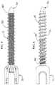
- FIG. 1shows a side elevation view of a fixation device according to one embodiment of the present disclosure
- FIG. 2shows a detailed view of the fixation device of FIG. 1 ;
- FIG. 3shows a sectional view of a fixation device according to another embodiment of the present disclosure
- FIG. 4shows a detailed view of the fixation device of FIG. 3 ;
- FIG. 5shows a sectional view of a fixation device according to another embodiment of the present disclosure
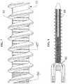
- FIG. 6shows an elevation view of a fixation device according to another embodiment of the present disclosure
- FIG. 7shows a detailed view of the fixation device of FIG. 6 ;
- FIG. 8shows a sectional view of a fixation device according to another embodiment of the present disclosure.
- FIG. 9shows a perspective, sectional view of the fixation device of FIG. 8 ;
- fixation devices shown in FIGS. 1-9preferably comprise a porous or fenestrated structure, which may be exposed at specific regions along the fixation device, and which aid with osteo-integration while increasing the mechanical stability of the device.
- the fixation deviceis provided in the form of a screw having a head portion 10 and a distal portion 20 , with threads 30 located on the shaft 15 between the head portion 10 and the distal portion 20 .
- the head portion 10is affixed to the body of the fixation device, while in other embodiments the head is allowed to float and thereby provide a poly-axial screw assembly.
- the headmay be temporarily attached to the body of the fixation device.
- the porous or fenestrated structureis comprised of the shaft 15 of the screw, but not covering the head portion 10 or the threads 30 . The number of fenestrations or porosity of the porous structure of the screw may be greater or lesser than depicted in FIG. 1 .
- the fenestrations 40are arranged in series and extend substantially the entire width of the shaft 15 between the threads 30 .
- the fenestrationsmay be fewer in number than shown, and may not be uniform in their location and arrangement.
- the fenestrationsmay be circular or any other shape suitable for the fixation device.
- the fenestrationsextend even through the threads 30 of the screw.
- the screwmay be additively manufactured such that the porous structure may be exposed to the interfacing bone but also contained within the core of the screw.
- the screwmay be additively manufactured, by way of example but not limitation, out of biocompatible alloys, including by using electron-beam melting or selective laser sintering methods to produce various surface finishes on the porous and solid aspects of the screw.
- the screwmay be a manufactured as a single part, fixed angle screw, or may be poly-axial.
- the screwmay comprise a substantially hollow section that is in communication with the plurality of fenestrations 40 .
- the screwmay comprise a porous structure in a solid core to provide superior mechanical characteristics.
- the porous structuremay be confined to only a certain region of the screw, or may extend substantially the entire length of the screw.
- the fenestrations 40may extend the entire width of the screw for substantially the entire length of the shaft 15 , as shown. In this manner, the number of fenestrations 40 may be increased, thereby increasing the number of locations along the outer surface of the screw that either material can be introduced (via the screw) or material may be collected (via suction as described above).
- the screwmay have a longitudinal channel 35 that runs lengthwise through the screw and permits material to be introduced through the longitudinal channel and into the plurality of fenestrations 40 .
- the longitudinal channelmay be accessible from the head portion 10 of the screw, such that an operator may inject fluid or solid material into the longitudinal channel 35 and ultimately through the porous structure of the screw via fenestrations 40 .
- the fenestrations 40(which surround the outer surface of the shaft 15 of the screw) may be used with vacuum or suction applied to the head portion 10 of the screw to retract material adjacent to the fenestrations 40 and either retained by the porous structure of the screw or within the longitudinal channel 35 .
- the screwcould either be infused with bone morphogenetic protein or equivalent to enhance fusion between the screw and the patient's anatomy, or the screw could suction and retain autogenous blood into the fenestrations, which in turn stimulates bony ingrowth in the porous section of the screw. Variations on this embodiment are considered within the scope of the present disclosure.
- one embodimentcomprises a varying array of fenestrations 40 , which may increase or decrease along the length of the screw.
- the number of fenestrations 40may vary in a second portion of the screw, such that there is a decreased number or pattern of fenestrations 40 ′ than at a different portion of the screw.
- the shaft 15may not comprise any fenestrations at all. This variation is best shown in the detailed view of FIG. 7 .
- materialmay either be collected or introduced via the screw only at desired locations along the length of the screw, which may be desirable given the particular bone density and surrounding anatomical features of a particular patient.
- the longitudinal channelmay comprise additional fenestrations in certain portions to better accommodate a particular patient's anatomy.
- a first portion of the longitudinal channel 35is as depicted in FIG. 3
- a second portion of the longitudinal channel 35 ′may comprise a greater number of fenestrations and therefore a greater porosity.
- the fixation devicemay be a pedicle screw, which may be additively manufactured such that the solid and porous aspects of the screw are fused together into a single solid construct.
- the solid and porous structuremay be co-extensive with the porous elements interdigitated within and around various solid elements of the screw. Variations on these embodiments are considered within the spirit of the presently claimed invention.
- porous elements of the fixation device, screw or implantmay be designed to more closely resemble that of a specific patient's anatomy. Accordingly, one advantage of the present disclosure is to promote bony ingrowth throughout the porous portions or sections of the implant, which in turn reduces the risk of loosening of the device under dynamic loading situations.
- only a portion of the screwis manufactured with a porous surface.
- the exposed porous aspects of the screwmay be localized along the minor diameter of the thread form.
- the screwmay therefore comprise hollow, porous or solid core elements to allow for varying levels of implant stiffness. These areas may be surrounded by a mostly solid thread form to facilitate smooth implantation and firm seating of the screw. Particular reference is made to FIGS. 3-4 when referring to this embodiment.
- the porous elements of the screwmay be designed with localized fenestrations, which may be at least partially accessible from the screw head, and thereby facilitate delivery of osteogenic agents such as bone-morphogenetic proteins, HA and or allograph or autograph tissue into the porous portions of the screw. This in turn allows for bony ingrowth and greater pullout resistance, as described above.
- the exposed porous structuremay be located on the proximal portion of the screw, adjacent the screw head, in order to localize ingrowth. Localization of ingrowth may increase mechanical characteristics of the bone screw interface, and subsequently allow for easier implant removal in the case of revision surgery.
- the localized porous elementsmay be tapered outward to increase the interference fit of the porous elements with the surrounding anatomy.
- the porous featuresare representative of porous cancellous bone with porosity preferably ranging between 30-80% to allow for ingrowth of osteocytes and supporting vasculature. Stated another way, the porous features, when compared to the solid features of the device, make up about 30-80% of the volume of the device. In a most preferred embodiment, the porosity is about 50%. In certain embodiments, the porous structure may be regular and geometric or irregular in form. In yet other embodiments, the porous density may be homogenous throughout the screw, or may be heterogeneous in order to attain desired stiffness and or improve the structural interface of the solid and porous elements.
- the implant length and diametermay be pre-surgically planned to match the anatomical size of the patient's anatomy.
- the implant porosity and subsequent modulusmay be pre-surgically planned to match the bone density of the intended patient.
- the surgical devices described abovemay be matched to an anatomic feature of a patient that has degenerated and needs to be restored.
- the surgical devicemay be necessary to correct structural or physiological deformities present in the patient anatomy, and thereby serve to correct position or alignment of the patient anatomy.
- Other devicesmay be patient specific but do not serve a restorative or “structural” function.
- the surgical devices described hereinmay be manufactured via additive manufacturing.
- the surgical devicesmay be used in all approaches (anterior, direct lateral, transforaminal, posterior, posterior lateral, direct lateral posterior, etc).
- Specific features of the surgical devicecan address certain surgical objectives, for example restoring lordosis, restoring disc height, restoring sagittal or coronal balance, etc.
- the fixation and surgical devices described hereinmay then be fabricated by any method.
- Fabrication methodsmay comprise the use of a rapid prototyping machine, a 3D printing machine, a stereolithography (STL) machine, selective laser sintering (SLS) machine, or a fused deposition modeling (FDM) machine, direct metal laser sintering (DMLS), electron beam melting (EBM) machine, or other additive manufacturing machine.
- a rapid prototyping machinea 3D printing machine, a stereolithography (STL) machine, selective laser sintering (SLS) machine, or a fused deposition modeling (FDM) machine, direct metal laser sintering (DMLS), electron beam melting (EBM) machine, or other additive manufacturing machine.
- STLstereolithography
- SLSselective laser sintering
- FDMfused deposition modeling
- DMLSdirect metal laser sintering
- EBMelectron beam melting
- the outer surfaces of the fixation devicemay further comprise one or more spikes or teeth or other surface features, which serve to contact and at least partially penetrate or “grip” the patient anatomy to secure the fixation device in place.
- the surface featuresmay be made of the same material and may be permanently attached to the fixation device.
- the surface featuresmay be comprised of an overlay, and/or may be made of a different material, such as the ones described herein, and may further be selectively inserted onto the fixation device(s) as desired.
- embodiments of the present disclosuremay have various sizes.
- the sizes of the various elements of embodiments of the present disclosuremay be sized based on various factors including, for example, the anatomy of the patient, the person or other device operating with or otherwise using the apparatus, the surgical site location, physical features of the devices and instruments used with the apparatus described herein, including, for example, width, length and thickness, and the size of the surgical apparatus.
- embodiments of the present disclosuremay be constructed of materials known to provide, or predictably manufactured to provide the various aspects of the present disclosure. These materials may include, for example, stainless steel, titanium alloy, aluminum alloy, chromium alloy, and other metals or metal alloys. These materials may also include, for example, PEEK, carbon fiber, ABS plastic, polyurethane, polyethylene, photo-polymers, resins, particularly fiber-encased resinous materials, rubber, latex, synthetic rubber, synthetic materials, polymers, and natural materials.
- embodiments of the present disclosuremay be used in conjunction devices that employ automated or semi-automated manipulation.
- Various apparatus and implants described hereinmay be provided to facilitate or control the entry point, angular trajectory, height, and/or head orientation of a screw, for example. This is desirable, particularly with placement of screws in the human body, as it permits a surgeon/user to optimize spinal screw head alignment for subsequent rod insertion across multiple bony landmarks.
- a patient specific rodmay be designed and manufactured to either match the pre-planned screw placement, or offer angular corrections in order to optimize curvature of the spine.
- surgical devicesmay soon be capable of fabrication in a number of different and convenient settings, including but not limited to an off-site manufacturing location, an on-site manufacturing location, using equipment present in a surgeon's clinic or offices or in a public or private hospital.
- modulesmay be fabricated based on a particular patient need and immediately fabricated once the need is identified, and then provided directly to the surgeon.
- Additional benefits of the systems and methods described hereininclude improving device fixation, and/or preventing unwanted contact between devices and patient anatomy (e.g. the patient's spinal cord).
- the further use of methods described above, including the use of software analytics,may further aid in determining screw placement and orientation to achieve the ideal screw placement and/or rod shape.
- the use of various apparatus described herein to achieve desired screw placement and orientationin turn provides improved alignment of a secondary device, such as a rod, with the screws heads. This benefit in turn allows the surgeon/user to achieve optimal sagittal and/or coronal alignment, which assists in rod placement and improves correction of the patient's anatomy.
- a patientcould be either a human patient or an animal patient, and the apparatus and methods described herein apply equally to veterinary science as they would to surgical procedures performed on human anatomy.
- the apparatus and methods described hereintherefore have application beyond surgical procedures used by spinal surgeons, and the concepts may be applied to other types of “patients” and procedures without departing from the spirit of the present disclosure.
- the present inventionsinclude components, methods, processes, systems and/or apparatuses substantially as depicted and described herein, including various embodiments, subcombinations, and subsets thereof. Those of skill in the art will understand how to make and use the present inventions after understanding the present disclosure.
- the present inventionsinclude providing devices and processes in the absence of items not depicted and/or described herein or in various embodiments hereof, including in the absence of such items as may have been used in previous devices or processes, e.g., for improving performance, achieving ease and/or reducing cost of implementation.
Landscapes
- Health & Medical Sciences (AREA)
- Orthopedic Medicine & Surgery (AREA)
- Life Sciences & Earth Sciences (AREA)
- Surgery (AREA)
- Engineering & Computer Science (AREA)
- Neurology (AREA)
- Biomedical Technology (AREA)
- General Health & Medical Sciences (AREA)
- Heart & Thoracic Surgery (AREA)
- Animal Behavior & Ethology (AREA)
- Public Health (AREA)
- Veterinary Medicine (AREA)
- Medical Informatics (AREA)
- Nuclear Medicine, Radiotherapy & Molecular Imaging (AREA)
- Molecular Biology (AREA)
- Transplantation (AREA)
- General Physics & Mathematics (AREA)
- Physics & Mathematics (AREA)
- Oral & Maxillofacial Surgery (AREA)
- Chemical & Material Sciences (AREA)
- Cardiology (AREA)
- Vascular Medicine (AREA)
- Business, Economics & Management (AREA)
- Educational Administration (AREA)
- Computational Mathematics (AREA)
- Physical Education & Sports Medicine (AREA)
- Mathematical Analysis (AREA)
- Mathematical Optimization (AREA)
- Mathematical Physics (AREA)
- Pure & Applied Mathematics (AREA)
- Medicinal Chemistry (AREA)
- Algebra (AREA)
- Educational Technology (AREA)
- Theoretical Computer Science (AREA)
- Prostheses (AREA)
- Surgical Instruments (AREA)
- Dentistry (AREA)
- Manufacturing & Machinery (AREA)
- Materials Engineering (AREA)
- Robotics (AREA)
Abstract
Description
This application is a continuation-in-part of U.S. patent application Ser. No. 15/416,975, filed on Jan. 26, 2017. This application also claims priority under 35 U.S.C. § 119(e) to U.S. Provisional Application No. 62/373,855, filed Aug. 11, 2016.
The present disclosure relates to the field of medical devices generally. More specifically, the present disclosure relates to a fixation device, such as a screw, comprising one or more fenestrations. Systems and methods for using the foregoing devices are also disclosed herein.
Individuals who suffer degenerative disc disease, natural spine deformations, a herniated disc, spine injuries or other spine disorders often require surgery on the affected region to relieve pain and prevent further injury. Such spinal surgeries may involve fixation of two or more adjacent vertebral bodies. For patients with varying degrees of degenerative disc disease and/or nerve compression with associated lower back pain, spinal fusion surgery or lumbar arthrodesis (“fusion”) is commonly used to treat the degenerative disease. Fusion commonly involves distracting and/or decompressing one or more intervertebral spaces, followed by removing any associated facet joints or discs, and then joining or “fusing” two or more adjacent vertebra together. Fusion of vertebral bodies also commonly involves fixation of two or more adjacent vertebrae, which may be accomplished through introduction of rods or plates, and screws or other devices into a vertebral joint to join various portions of a vertebra to a corresponding portion on an adjacent vertebra. Given the complexities of surgical procedures, as well as anatomical variation between patients who receive surgical devices, it is often challenging to provide a device or implant that achieves the needs of a particular patient without completely customizing the device or implant for a single patient.
Many prior art fixation devices suffer from significant disadvantages, such as poor stability, poor flexibility, poor accuracy, difficulty in handling, lack of customized features, inability to combine with other materials, loss of fixation over time, subsidence and other disadvantages. Certain fixation devices also impair visibility and provide little or no ability for the operator to gauge depth or accuracy. These problems and shortcomings are even more noticeable for fixation devices used in surgical settings or which otherwise require precision.
In addition, fixation devices used in surgical settings can also suffer from further shortcomings. For example, pedicle screws are subject to relatively high failure rates, which is often attributed to a failure of the bone-screw interface. Screws for use in surgical settings may also be limited for use in only certain bony anatomies, or with only certain types of drilling apparatus, and may not be suitable for combination with other devices or materials.
Accordingly, there is a need for a fixation device that decreases the mean time for affixing the device to the desired location, enhances depth control, stability and accuracy, and which otherwise overcomes the disadvantages of the prior art. There is also need for a more customized fixation device, such as an orthopedic screw, which includes one or more porous elements or fenestrations to aid in osteo-integration when implanting the fixation device. The fixation device may be additively manufactured using biocompatible materials such that the solid and porous aspects of the device are fused together into a single solid construct, and potentially having the porous elements interdigitated within and around various solid elements of the device.
The prior art also fails to teach a system for creating a customized fixation device based on patient data, such as data derived from a patient's MRI or CT scan. For example, the availability of patient-specific data (for example, a vertebral body) may allow a surgeon to accommodate for subtle variations in the position and orientation of a screw or other fixation device to avoid particular bony anatomy, or irregularities in the positioning and alignment of the adjoining vertebral bodies. As another example, the use of patient data may also assist a surgeon in selecting a desired trajectory for an fixation device so as to avoid, for example, crossing the pedicle wall and violating the spinal canal during a spine-related procedure. The use of patient-specific data permits the surgeon to avoid these types of mistakes and may comprise specific orientation, end-stops/hard stops, or other safety related features to avoid over-torque or over-insertion of the fixation device. This data also permits the surgeon to quickly and efficiently locate and place devices with corresponding patient-contacting surface(s), while ensuring the fixation device is in the appropriate location and orientation.
It would therefore be advantageous to provide a fixation device that significantly reduces, if not eliminates, the shortcoming, problems and risks noted above. Other advantages over the prior art will become known upon review of the Summary and Detailed Description and the appended claims.
According to various embodiments presented herein, the present disclosure describes a fixation device, such as a screw, comprising one or more fenestrations which permit introduction of at least one other material or substance to through the fenestrations in the fixation device. In other embodiments, the fenestrations permit the fixation device to capture and retain material. In yet another aspect of the present disclosure, a method of using the fixation devices described herein is disclosed, including but not limited to in a surgical setting.
One particular aspect of the present disclosure involves a fixation device, such as an orthopedic pedicle screw or implant, that is manufactured such that it includes one or more porous elements or fenestrations in order to aid in osteo-integration of the implanted fixation device. For instance, a pedicle screw (as one type of fixation device) may be additively manufactured using biocompatible materials such that the solid and porous aspects of the screw are fused together into a single solid construct with the porous elements interdigitated within and around various solid elements of the screw.
In yet another aspect, a surgical screw design having at least a portion or section incorporating a porous structure enables bony ingrowth through the porous section/portion of the screw, and thereby facilitate biocompatibility and improve mechanical characteristics. The porous elements of the screw may be designed to more closely resemble that of the patient's anatomy, in order to reduce discontinuities and stress risers at the bone/screw interface. Bony ingrowth within one or more porous elements of the screw in turn facilitates screw pullout strength, and may reduce the risk of loosening of a fixation device under dynamic loading situations.
Incorporated by reference in their entireties are the following U.S. patents and patent applications directed generally to methods and apparatus related to surgical procedures, thus providing written description support for various aspects of the present disclosure. The U.S. patents and pending applications incorporated by reference are as follows: U.S. Pat. Nos. 7,957,824, 7,844,356, 7,658,610, 6,830,570, 6,368,325, 3,486,505 and U.S. Pat. Pub. Nos. 2010/0217336, 2009/0138020, 2009/0087276, 2008/0161817, 2008/0114370, and 2007/0270875.
Additionally, U.S. Pat. Nos. 8,758,357, 8,870,889, 9,198,678 and 9,642,633 are incorporated by reference for the express purpose of illustrating systems and methods for creating a device, such as the one described herein, using additive manufacturing or other techniques, wherein the device incorporates one or more patient-matched surfaces or is otherwise customized to a particular patient.
The phrases “at least one,” “one or more,” and “and/or,” as used herein, are open-ended expressions that are both conjunctive and disjunctive in operation. For example, each of the expressions “at least one of A, B and C,” “at least one of A, B, or C,” “one or more of A, B, and C,” “one or more of A, B, or C,” and “A, B, and/or C” means A alone, B alone, C alone, A and B together, A and C together, B and C together, or A, B and C together.
Unless otherwise indicated, all numbers expressing quantities, dimensions, conditions, and so forth used in the specification and claims are to be understood as being approximations which may be modified in all instances as required for a particular application of the novel apparatus described herein.
The term “a” or “an” entity, as used herein, refers to one or more of that entity. As such, the terms “a” (or “an”), “one or more” and “at least one” can be used interchangeably herein.
The use of “including,” “comprising,” or “having” and variations thereof herein is meant to encompass the items listed thereafter and equivalents thereof as well as additional items. Accordingly, the terms “including,” “comprising,” or “having” and variations thereof can be used interchangeably herein.
It shall be understood that the term “means” as used herein shall be given its broadest possible interpretation in accordance with 35 U.S.C., Section 112(f). Accordingly, a claim incorporating the term “means” shall cover all structures, materials, or acts set forth herein, and all of the equivalents thereof. Further, the structures, materials, or acts and the equivalents thereof shall include all those described in the Summary, Brief Description of the Drawings, Detailed Description, Abstract, and Claims themselves.
The Summary is neither intended, nor should it be construed, as being representative of the full extent and scope of the present disclosure. Moreover, references made herein to “the present disclosure” or aspects thereof should be understood to mean certain embodiments of the present disclosure, and should not necessarily be construed as limiting all embodiments to a particular description. The present disclosure is set forth in various levels of detail in the Summary as well as in the attached drawings and the Detailed Description, and no limitation as to the scope of the present disclosure is intended by either the inclusion or non-inclusion of elements or components when describing certain embodiments herein. Additional aspects of the present disclosure will become more readily apparent from the Detailed Description, particularly when taken together with the drawings.
The above-described benefits, embodiments, and/or characterizations are not necessarily complete or exhaustive, and in particular, as to the patentable subject matter disclosed herein. Other benefits, embodiments, and/or characterizations of the present disclosure are possible utilizing, alone or in combination, as set forth above and/or described in the accompanying figures and/or in the description herein below.
The accompanying drawings, which are incorporated herein and constitute a part of the specification, illustrate embodiments of the disclosure, and together with the Summary and the Detailed Description serve to explain the principles of these embodiments. In certain instances, details that are not necessary for an understanding of the disclosure or that render other details difficult to perceive may have been omitted. It should be understood, of course, that the present disclosure is not necessarily limited to the particular embodiments illustrated herein. Additionally, it should be understood that the drawings are not necessarily to scale. In the drawings:
Similar components and/or features may have the same reference number. Components of the same type may be distinguished by a letter following the reference number. If only the reference number is used, the description is applicable to any one of the similar components having the same reference number.
The present disclosure has significant benefits across a broad spectrum of endeavors. It is the Applicant's intent that this specification and the claims appended hereto be accorded a breadth in keeping with the scope and spirit of the disclosure and various embodiments disclosed, despite what might appear to be limiting language imposed by specific examples disclosed in the specifications. To acquaint persons skilled in the pertinent arts most closely related to the present disclosure, preferred and/or exemplary embodiments are described in detail without attempting to describe all of the various forms and modifications in which the novel apparatus, devices, systems and methods might be embodied. As such, the embodiments described herein are illustrative, and as will become apparent to those skilled in the arts, may be modified in numerous ways within the spirit of the disclosure.
By way of providing additional background, context, and to further satisfy the written description requirements of 35 U.S.C. § 112, the following are incorporated by reference in their entireties for the express purpose of explaining and further describing the various tools and other apparatus commonly associated therewith surgical procedures, including minimally invasive surgery (“MIS”) procedures: U.S. Pat. No. 6,309,395 to Smith et al.; U.S. Pat. No. 6,142,998 to Smith et al.; U.S. Pat. No. 7,014,640 to Kemppanien et al.; U.S. Pat. No. 7,406,775 to Funk, et al.; U.S. Pat. No. 7,387,643 to Michelson; U.S. Pat. No. 7,341,590 to Ferree; U.S. Pat. No. 7,288,093 to Michelson; U.S. Pat. No. 7,207,992 to Ritland; U.S. Pat. No. 7,077,864 Byrd III, et al.; U.S. Pat. No. 7,025,769 to Ferree; U.S. Pat. No. 6,719,795 to Cornwall, et al.; U.S. Pat. No. 6,364,880 to Michelson; U.S. Pat. No. 6,328,738 to Suddaby; U.S. Pat. No. 6,290,724 to Marino; U.S. Pat. No. 6,113,602 to Sand; U.S. Pat. No. 6,030,401 to Marino; U.S. Pat. No. 5,865,846 to Bryan, et al.; U.S. Pat. No. 5,569,246 to Ojima, et al.; U.S. Pat. No. 5,527,312 to Ray; and U.S. Pat. Appl. No. 2008/0255564 to Michelson.
Referring now toFIGS. 1-9 , varying embodiments of the present disclosure are shown. The fixation devices shown inFIGS. 1-9 preferably comprise a porous or fenestrated structure, which may be exposed at specific regions along the fixation device, and which aid with osteo-integration while increasing the mechanical stability of the device. Various benefits of the fixation device, which in a preferred embodiment is in the form of a screw, are described herein.
In the embodiment ofFIG. 1 , the fixation device is provided in the form of a screw having a head portion10 and adistal portion 20, withthreads 30 located on the shaft15 between the head portion10 and thedistal portion 20. In certain embodiments, the head portion10 is affixed to the body of the fixation device, while in other embodiments the head is allowed to float and thereby provide a poly-axial screw assembly. In other embodiments, the head may be temporarily attached to the body of the fixation device. According to this particular embodiment, the porous or fenestrated structure is comprised of the shaft15 of the screw, but not covering the head portion10 or thethreads 30. The number of fenestrations or porosity of the porous structure of the screw may be greater or lesser than depicted inFIG. 1 .
Referring now toFIG. 2 , a detailed view of the porous screw is depicted. In this drawing, thefenestrations 40 are arranged in series and extend substantially the entire width of the shaft15 between thethreads 30. In alternate embodiments, the fenestrations may be fewer in number than shown, and may not be uniform in their location and arrangement. The fenestrations may be circular or any other shape suitable for the fixation device. In alternate embodiments, the fenestrations extend even through thethreads 30 of the screw.
The screw may be additively manufactured such that the porous structure may be exposed to the interfacing bone but also contained within the core of the screw. The screw may be additively manufactured, by way of example but not limitation, out of biocompatible alloys, including by using electron-beam melting or selective laser sintering methods to produce various surface finishes on the porous and solid aspects of the screw. The screw may be a manufactured as a single part, fixed angle screw, or may be poly-axial.
Referring now toFIGS. 3-4 , the screw may comprise a substantially hollow section that is in communication with the plurality offenestrations 40. For example, as shown inFIG. 3 , the screw may comprise a porous structure in a solid core to provide superior mechanical characteristics. The porous structure may be confined to only a certain region of the screw, or may extend substantially the entire length of the screw.
Referring now toFIG. 5 , thefenestrations 40 may extend the entire width of the screw for substantially the entire length of the shaft15, as shown. In this manner, the number offenestrations 40 may be increased, thereby increasing the number of locations along the outer surface of the screw that either material can be introduced (via the screw) or material may be collected (via suction as described above). In embodiments, the screw may have alongitudinal channel 35 that runs lengthwise through the screw and permits material to be introduced through the longitudinal channel and into the plurality offenestrations 40. For example, the longitudinal channel may be accessible from the head portion10 of the screw, such that an operator may inject fluid or solid material into thelongitudinal channel 35 and ultimately through the porous structure of the screw viafenestrations 40. In a similar manner, the fenestrations40 (which surround the outer surface of the shaft15 of the screw) may be used with vacuum or suction applied to the head portion10 of the screw to retract material adjacent to thefenestrations 40 and either retained by the porous structure of the screw or within thelongitudinal channel 35. By way of example, the screw could either be infused with bone morphogenetic protein or equivalent to enhance fusion between the screw and the patient's anatomy, or the screw could suction and retain autogenous blood into the fenestrations, which in turn stimulates bony ingrowth in the porous section of the screw. Variations on this embodiment are considered within the scope of the present disclosure.
Referring toFIG. 6 , one embodiment comprises a varying array offenestrations 40, which may increase or decrease along the length of the screw. As shown inFIG. 6 , the number offenestrations 40 may vary in a second portion of the screw, such that there is a decreased number or pattern offenestrations 40′ than at a different portion of the screw. In other portions of the screw, the shaft15 may not comprise any fenestrations at all. This variation is best shown in the detailed view ofFIG. 7 . In this manner, material may either be collected or introduced via the screw only at desired locations along the length of the screw, which may be desirable given the particular bone density and surrounding anatomical features of a particular patient. In reference toFIGS. 6 and 7 , in certain embodiments the longitudinal channel may comprise additional fenestrations in certain portions to better accommodate a particular patient's anatomy. For instance, a first portion of thelongitudinal channel 35 is as depicted inFIG. 3 , while a second portion of thelongitudinal channel 35′ may comprise a greater number of fenestrations and therefore a greater porosity.
Further variations of the embodiments described above are shown inFIGS. 8-9 . For example, the fixation device may be a pedicle screw, which may be additively manufactured such that the solid and porous aspects of the screw are fused together into a single solid construct. In other embodiments, the solid and porous structure may be co-extensive with the porous elements interdigitated within and around various solid elements of the screw. Variations on these embodiments are considered within the spirit of the presently claimed invention.
The porous elements of the fixation device, screw or implant may be designed to more closely resemble that of a specific patient's anatomy. Accordingly, one advantage of the present disclosure is to promote bony ingrowth throughout the porous portions or sections of the implant, which in turn reduces the risk of loosening of the device under dynamic loading situations.
In still other embodiments, only a portion of the screw is manufactured with a porous surface. For example, the exposed porous aspects of the screw may be localized along the minor diameter of the thread form. The screw may therefore comprise hollow, porous or solid core elements to allow for varying levels of implant stiffness. These areas may be surrounded by a mostly solid thread form to facilitate smooth implantation and firm seating of the screw. Particular reference is made toFIGS. 3-4 when referring to this embodiment.
As referred to above, the porous elements of the screw may be designed with localized fenestrations, which may be at least partially accessible from the screw head, and thereby facilitate delivery of osteogenic agents such as bone-morphogenetic proteins, HA and or allograph or autograph tissue into the porous portions of the screw. This in turn allows for bony ingrowth and greater pullout resistance, as described above. The exposed porous structure may be located on the proximal portion of the screw, adjacent the screw head, in order to localize ingrowth. Localization of ingrowth may increase mechanical characteristics of the bone screw interface, and subsequently allow for easier implant removal in the case of revision surgery. The localized porous elements may be tapered outward to increase the interference fit of the porous elements with the surrounding anatomy.
The porous features are representative of porous cancellous bone with porosity preferably ranging between 30-80% to allow for ingrowth of osteocytes and supporting vasculature. Stated another way, the porous features, when compared to the solid features of the device, make up about 30-80% of the volume of the device. In a most preferred embodiment, the porosity is about 50%. In certain embodiments, the porous structure may be regular and geometric or irregular in form. In yet other embodiments, the porous density may be homogenous throughout the screw, or may be heterogeneous in order to attain desired stiffness and or improve the structural interface of the solid and porous elements.
The implant length and diameter may be pre-surgically planned to match the anatomical size of the patient's anatomy. The implant porosity and subsequent modulus may be pre-surgically planned to match the bone density of the intended patient. For example, in one embodiment, the surgical devices described above may be matched to an anatomic feature of a patient that has degenerated and needs to be restored. In another embodiment, the surgical device may be necessary to correct structural or physiological deformities present in the patient anatomy, and thereby serve to correct position or alignment of the patient anatomy. Other devices may be patient specific but do not serve a restorative or “structural” function.
The surgical devices described herein may be manufactured via additive manufacturing. In the context of spinal implants, the surgical devices may be used in all approaches (anterior, direct lateral, transforaminal, posterior, posterior lateral, direct lateral posterior, etc). Specific features of the surgical device can address certain surgical objectives, for example restoring lordosis, restoring disc height, restoring sagittal or coronal balance, etc. The fixation and surgical devices described herein may then be fabricated by any method. Fabrication methods may comprise the use of a rapid prototyping machine, a 3D printing machine, a stereolithography (STL) machine, selective laser sintering (SLS) machine, or a fused deposition modeling (FDM) machine, direct metal laser sintering (DMLS), electron beam melting (EBM) machine, or other additive manufacturing machine.
To add further stability to the seating and placement of the fixation devices described herein to the patient anatomy, the outer surfaces of the fixation device may further comprise one or more spikes or teeth or other surface features, which serve to contact and at least partially penetrate or “grip” the patient anatomy to secure the fixation device in place. In one embodiment, the surface features may be made of the same material and may be permanently attached to the fixation device. In another embodiment, the surface features may be comprised of an overlay, and/or may be made of a different material, such as the ones described herein, and may further be selectively inserted onto the fixation device(s) as desired.
One having skill in the art will appreciate that embodiments of the present disclosure may have various sizes. The sizes of the various elements of embodiments of the present disclosure may be sized based on various factors including, for example, the anatomy of the patient, the person or other device operating with or otherwise using the apparatus, the surgical site location, physical features of the devices and instruments used with the apparatus described herein, including, for example, width, length and thickness, and the size of the surgical apparatus.
One having skill in the art will appreciate that embodiments of the present disclosure may be constructed of materials known to provide, or predictably manufactured to provide the various aspects of the present disclosure. These materials may include, for example, stainless steel, titanium alloy, aluminum alloy, chromium alloy, and other metals or metal alloys. These materials may also include, for example, PEEK, carbon fiber, ABS plastic, polyurethane, polyethylene, photo-polymers, resins, particularly fiber-encased resinous materials, rubber, latex, synthetic rubber, synthetic materials, polymers, and natural materials.
One having skill in the art will appreciate that embodiments of the present disclosure may be used in conjunction devices that employ automated or semi-automated manipulation. Various apparatus and implants described herein may be provided to facilitate or control the entry point, angular trajectory, height, and/or head orientation of a screw, for example. This is desirable, particularly with placement of screws in the human body, as it permits a surgeon/user to optimize spinal screw head alignment for subsequent rod insertion across multiple bony landmarks. Additionally, by controlling screw placement, a patient specific rod may be designed and manufactured to either match the pre-planned screw placement, or offer angular corrections in order to optimize curvature of the spine.
The present disclosure may also be advantageous in light of recent improvements in decentralized manufacturing. For example, surgical devices may soon be capable of fabrication in a number of different and convenient settings, including but not limited to an off-site manufacturing location, an on-site manufacturing location, using equipment present in a surgeon's clinic or offices or in a public or private hospital. For example, modules may be fabricated based on a particular patient need and immediately fabricated once the need is identified, and then provided directly to the surgeon.
Additional benefits of the systems and methods described herein include improving device fixation, and/or preventing unwanted contact between devices and patient anatomy (e.g. the patient's spinal cord). The further use of methods described above, including the use of software analytics, may further aid in determining screw placement and orientation to achieve the ideal screw placement and/or rod shape. For example, the use of various apparatus described herein to achieve desired screw placement and orientation in turn provides improved alignment of a secondary device, such as a rod, with the screws heads. This benefit in turn allows the surgeon/user to achieve optimal sagittal and/or coronal alignment, which assists in rod placement and improves correction of the patient's anatomy.
While various embodiments of the present disclosure have been described in detail, it is apparent that modifications and alterations of those embodiments will occur to those skilled in the art. However, it is to be expressly understood that such modifications and alterations are within the scope and spirit of the present disclosure, as set forth in the following claims. For further illustration, the information and materials supplied with the provisional and non-provisional patent applications from which this application claims priority are expressly made a part of this disclosure and incorporated by reference herein in their entirety.
It is expressly understood that where the term “patient” has been used to describe the various embodiments of the disclosure, the term should not be construed as limiting in any way. For instance, a patient could be either a human patient or an animal patient, and the apparatus and methods described herein apply equally to veterinary science as they would to surgical procedures performed on human anatomy. The apparatus and methods described herein therefore have application beyond surgical procedures used by spinal surgeons, and the concepts may be applied to other types of “patients” and procedures without departing from the spirit of the present disclosure.
The foregoing discussion of the disclosure has been presented for purposes of illustration and description. The foregoing is not intended to limit the disclosure to the form or forms disclosed herein. In the foregoing Detailed Description for example, various features of the disclosure are grouped together in one or more embodiments for the purpose of streamlining the disclosure. This method of disclosure is not to be interpreted as reflecting an intention that the claimed disclosure requires more features than are expressly recited in each claim. Rather, as the following claims reflect, inventive aspects lie in less than all features of a single foregoing disclosed embodiment. Thus, the following claims are hereby incorporated into this Detailed Description, with each claim standing on its own as a separate preferred embodiment of the disclosure.
The present inventions, in various embodiments, include components, methods, processes, systems and/or apparatuses substantially as depicted and described herein, including various embodiments, subcombinations, and subsets thereof. Those of skill in the art will understand how to make and use the present inventions after understanding the present disclosure. The present inventions, in various embodiments, include providing devices and processes in the absence of items not depicted and/or described herein or in various embodiments hereof, including in the absence of such items as may have been used in previous devices or processes, e.g., for improving performance, achieving ease and/or reducing cost of implementation.
Moreover, though the present disclosure has included description of one or more embodiments and certain variations and modifications, other variations and modifications are within the scope of the disclosure, e.g., as may be within the skill and knowledge of those in the art, after understanding the present disclosure. It is intended to obtain rights which include alternative embodiments to the extent permitted, including alternate, interchangeable and/or equivalent structures, functions, ranges or steps to those claimed, whether or not such alternate, interchangeable and/or equivalent structures, functions, ranges or steps are disclosed herein, and without intending to publicly dedicate any patentable subject matter.
Claims (20)
1. A device configured for fixation to a particular anatomical feature comprising:
a proximal portion of the device comprising a head for manipulation of the device by at least one tool or instrument, and a distal portion of the device comprising a tip configured to penetrate a surface of the particular anatomical feature;
a shaft portion between the proximal portion and the distal portion of the device, the shaft portion comprising at least one thread and further comprising one or more fenestrations along an outer surface thereof;
one or more spikes or teeth comprised of an overlay associated with the exterior of the shaft and configured to interface with bone associated with a patient-specific anatomical feature;
an internal channel running substantially the entire length of the shaft portion and accessible from the proximal portion of the device, wherein the internal channel is further accessible by the one or more fenestrations; and
wherein the device is configured to receive a first material by the proximal portion and through the internal channel, and wherein the first material is distributed through the one or more fenestrations.
2. The device ofclaim 1 wherein the one or more fenestrations are located along the shaft portion of the device and along the at least one thread.
3. The device ofclaim 1 wherein the one or more fenestrations are in communication with the internal channel by pathways formed in the device.
4. The device ofclaim 3 wherein the fenestrations and pathways provide porosity of 30-50 percent in the shaft.
5. The device ofclaim 3 wherein the fenestrations and pathways provide porosity of 50-80 percent.
6. The device ofclaim 1 wherein the device is formed by a rapid prototyping machine, a 3D printing machine, a stereolithography (STL) machine, a selective laser sintering (SLS) machine, a fused deposition modeling (FDM) machine, a direct metal laser sintering (DMLS) machine, an electron beam melting (EBM) machine, or an additive manufacturing machine.
7. The device ofclaim 1 wherein the device is made of a stainless steel, a titanium alloy, an aluminum alloy, a chromium alloy, a metal alloy, a PEEK material, a carbon fiber material, an ABS plastic, a polyurethane, a polyethylene, a photo-polymer, a resin, a fiber-encased resinous material, a rubber, a latex, a synthetic rubber, a synthetic material, a polymer, or a natural material.
8. The device ofclaim 1 , further comprising a bone morphogenetic compound associated with the fenestrations.
9. A fixation device comprising:
a body;
the body comprising a proximal portion and a distal portion;
the proximal portion comprising a head configured for mating with at least one instrument or tool;
the distal portion comprising a tip configured to penetrate a surface;
the body further comprising a shaft portion between the proximal portion and the distal portion, the shaft portion comprising at least one thread;
the body further comprising a porous structure, wherein the porous structure is formed in the shaft portion and accessible from the exterior of the fixation device;
the body further comprising one or more spikes or teeth selectively inserted onto the exterior of the shaft; and
wherein the porous structure is adapted to receive a material to substantially fill the porous structure with the material.
10. The device ofclaim 9 wherein the porous structure comprises a plurality of hollow pathways within the body, and wherein the plurality of hollow pathways make up 30-80 percent of the volume of the device.
11. The device ofclaim 10 wherein the plurality of hollow pathways make up 50 percent of the volume of the device.
12. The device ofclaim 10 wherein the plurality of hollow pathways are intersecting within the shaft portion of the fixation device.
13. The device ofclaim 10 wherein the porous structure is formed along the shaft portion and along the at least one thread.
14. The device ofclaim 13 wherein the porous structure is non-uniform about the length of the shaft.
15. The device ofclaim 10 wherein the shaft portion is comprised of a first portion having a porous structure and a second portion devoid of a porous structure.
16. The device ofclaim 10 wherein the device is customized for implanting in a patient-specific anatomical feature.
17. The device ofclaim 16 wherein the device is customized for implanting using a patient-specific surgical guide.
18. The device ofclaim 17 wherein a length and a diameter of the body is configured to match the size of the patient-specific anatomical feature.
19. The device ofclaim 17 wherein porous structure is configured to be determined by a bone density of the patient-specific anatomical feature.
20. The device ofclaim 9 , further comprising a bone morphogenetic compound associated with the porous structure.
Priority Applications (6)
| Application Number | Priority Date | Filing Date | Title |
|---|---|---|---|
| US15/675,104US10758283B2 (en) | 2016-08-11 | 2017-08-11 | Fixation devices having fenestrations and methods for using the same |
| US15/985,373US10653454B2 (en) | 2007-07-13 | 2018-05-21 | Spinal fixation systems |
| US29/663,719USD895837S1 (en) | 2016-08-11 | 2018-09-18 | Surgical guide tray |
| US17/008,819US11376049B2 (en) | 2016-08-11 | 2020-09-01 | Fixation devices having fenestrations and methods for using the same |
| US17/807,823US11925400B2 (en) | 2016-08-11 | 2022-06-20 | Fixation devices having fenestrations and methods for using the same |
| US18/596,364US20250281213A1 (en) | 2016-08-11 | 2024-03-05 | Devices having porous structures and methods for using the same |
Applications Claiming Priority (3)
| Application Number | Priority Date | Filing Date | Title |
|---|---|---|---|
| US201662373855P | 2016-08-11 | 2016-08-11 | |
| US15/416,975US9987024B2 (en) | 2010-06-29 | 2017-01-26 | Patient-matched apparatus and methods for performing surgical procedures |
| US15/675,104US10758283B2 (en) | 2016-08-11 | 2017-08-11 | Fixation devices having fenestrations and methods for using the same |
Related Parent Applications (1)
| Application Number | Title | Priority Date | Filing Date |
|---|---|---|---|
| US15/416,975Continuation-In-PartUS9987024B2 (en) | 2007-07-13 | 2017-01-26 | Patient-matched apparatus and methods for performing surgical procedures |
Related Child Applications (3)
| Application Number | Title | Priority Date | Filing Date |
|---|---|---|---|
| US15/985,373ContinuationUS10653454B2 (en) | 2007-07-13 | 2018-05-21 | Spinal fixation systems |
| US17/008,819Continuation-In-PartUS11376049B2 (en) | 2016-08-11 | 2020-09-01 | Fixation devices having fenestrations and methods for using the same |
| US17/008,819ContinuationUS11376049B2 (en) | 2016-08-11 | 2020-09-01 | Fixation devices having fenestrations and methods for using the same |
Publications (2)
| Publication Number | Publication Date |
|---|---|
| US20180042646A1 US20180042646A1 (en) | 2018-02-15 |
| US10758283B2true US10758283B2 (en) | 2020-09-01 |
Family
ID=61160639
Family Applications (5)
| Application Number | Title | Priority Date | Filing Date |
|---|---|---|---|
| US15/675,104Active2038-07-03US10758283B2 (en) | 2007-07-13 | 2017-08-11 | Fixation devices having fenestrations and methods for using the same |
| US15/985,373Active2029-02-11US10653454B2 (en) | 2007-07-13 | 2018-05-21 | Spinal fixation systems |
| US29/663,719ActiveUSD895837S1 (en) | 2016-08-11 | 2018-09-18 | Surgical guide tray |
| US17/008,819Active2037-07-10US11376049B2 (en) | 2016-08-11 | 2020-09-01 | Fixation devices having fenestrations and methods for using the same |
| US17/807,823ActiveUS11925400B2 (en) | 2016-08-11 | 2022-06-20 | Fixation devices having fenestrations and methods for using the same |
Family Applications After (4)
| Application Number | Title | Priority Date | Filing Date |
|---|---|---|---|
| US15/985,373Active2029-02-11US10653454B2 (en) | 2007-07-13 | 2018-05-21 | Spinal fixation systems |
| US29/663,719ActiveUSD895837S1 (en) | 2016-08-11 | 2018-09-18 | Surgical guide tray |
| US17/008,819Active2037-07-10US11376049B2 (en) | 2016-08-11 | 2020-09-01 | Fixation devices having fenestrations and methods for using the same |
| US17/807,823ActiveUS11925400B2 (en) | 2016-08-11 | 2022-06-20 | Fixation devices having fenestrations and methods for using the same |
Country Status (1)
| Country | Link |
|---|---|
| US (5) | US10758283B2 (en) |
Cited By (15)
| Publication number | Priority date | Publication date | Assignee | Title |
|---|---|---|---|---|
| US11234830B2 (en) | 2019-02-14 | 2022-02-01 | Si-Bone Inc. | Implants for spinal fixation and or fusion |
| US11369419B2 (en) | 2019-02-14 | 2022-06-28 | Si-Bone Inc. | Implants for spinal fixation and or fusion |
| US11376049B2 (en)* | 2016-08-11 | 2022-07-05 | Mighty Oak Medical Inc. | Fixation devices having fenestrations and methods for using the same |
| US11471286B2 (en) | 2012-03-09 | 2022-10-18 | Si-Bone Inc. | Systems, devices, and methods for joint fusion |
| US11571245B2 (en) | 2019-11-27 | 2023-02-07 | Si-Bone Inc. | Bone stabilizing implants and methods of placement across SI joints |
| US11633292B2 (en) | 2005-05-24 | 2023-04-25 | Si-Bone Inc. | Apparatus, systems, and methods for the fixation or fusion of bone |
| US11752011B2 (en) | 2020-12-09 | 2023-09-12 | Si-Bone Inc. | Sacro-iliac joint stabilizing implants and methods of implantation |
| US11877756B2 (en) | 2017-09-26 | 2024-01-23 | Si-Bone Inc. | Systems and methods for decorticating the sacroiliac joint |
| US11900537B2 (en) | 2020-05-25 | 2024-02-13 | Technologies Shapeshift 3D Inc. | Method and device for constraining shape deformation of 3D objects |
| US12083026B2 (en) | 2019-12-09 | 2024-09-10 | Si-Bone Inc. | Sacro-iliac joint stabilizing implants and methods of implantation |
| US12220326B2 (en) | 2013-10-15 | 2025-02-11 | Si-Bone Inc. | Implant placement |
| US20250281213A1 (en)* | 2016-08-11 | 2025-09-11 | Mighty Oak Medical, Inc. | Devices having porous structures and methods for using the same |
| US12419668B2 (en) | 2019-11-21 | 2025-09-23 | Si-Bone Inc. | Rod coupling assemblies for bone stabilization constructs |
| US12427028B2 (en) | 2018-03-28 | 2025-09-30 | Si-Bone Inc. | Threaded implants and methods of use across bone segments |
| US12433733B2 (en) | 2023-08-15 | 2025-10-07 | Si-Bone Inc. | Pelvic stabilization implants, methods of use and manufacture |
Families Citing this family (15)
| Publication number | Priority date | Publication date | Assignee | Title |
|---|---|---|---|---|
| US9044321B2 (en) | 2012-03-09 | 2015-06-02 | Si-Bone Inc. | Integrated implant |
| EP3818947B1 (en) | 2012-05-04 | 2023-08-30 | SI-Bone, Inc. | Fenestrated implant |
| WO2014145902A1 (en) | 2013-03-15 | 2014-09-18 | Si-Bone Inc. | Implants for spinal fixation or fusion |
| JP6542362B2 (en) | 2014-09-18 | 2019-07-10 | エスアイ−ボーン・インコーポレイテッドSi−Bone, Inc. | Matrix implant |
| US10166033B2 (en) | 2014-09-18 | 2019-01-01 | Si-Bone Inc. | Implants for bone fixation or fusion |
| US12016573B2 (en) | 2016-08-11 | 2024-06-25 | Mighty Oak Medical, Inc. | Drill apparatus and surgical fixation devices and methods for using the same |
| EP3593745B1 (en)* | 2018-02-02 | 2024-10-09 | Stryker European Operations Holdings LLC | Orthopedic screw and porous structures thereof |
| US11213403B2 (en) | 2019-03-14 | 2022-01-04 | Medos International Sarl | Devices and methods for optimized spinal fixation |
| USD1044032S1 (en)* | 2020-05-27 | 2024-09-24 | Olympus Winter & Ibe Gmbh | Storage tray for medical tools |
| USD965815S1 (en)* | 2020-07-08 | 2022-10-04 | Retrofix Screws, Llc | Tray for orthopedic screws |
| USD966549S1 (en)* | 2020-07-24 | 2022-10-11 | Soclean Inc. | Accessory tray |
| KR102537768B1 (en)* | 2020-09-29 | 2023-05-31 | 주식회사 에이스메디코프 | Bone cement injection type pedicle screw and Surgical tool for spinal fixation equipped with the screw |
| KR102545243B1 (en)* | 2020-09-29 | 2023-06-20 | 주식회사 에이스메디코프 | Porous pedicle screw and Surgical tool for spinal fixation with the screw |
| TWI813158B (en)* | 2021-02-09 | 2023-08-21 | 尚品醫療器材股份有限公司 | Spinal fixation device |
| WO2022197537A1 (en)* | 2021-03-18 | 2022-09-22 | 3D Systems Incorporated | Devices and methods for registering an imaging model to an augmented reality system before or during surgery |
Citations (284)
| Publication number | Priority date | Publication date | Assignee | Title |
|---|---|---|---|---|
| US3151392A (en) | 1963-02-18 | 1964-10-06 | Arthur E Chambers | Suture cutter |
| US5092866A (en) | 1989-02-03 | 1992-03-03 | Breard Francis H | Flexible inter-vertebral stabilizer as well as process and apparatus for determining or verifying its tension before installation on the spinal column |
| US5129904A (en) | 1986-08-05 | 1992-07-14 | Illi Oscar E | Osteosynthetic implant |
| US5201734A (en) | 1988-12-21 | 1993-04-13 | Zimmer, Inc. | Spinal locking sleeve assembly |
| US5291901A (en) | 1991-09-24 | 1994-03-08 | Henry Graf | Device for measuring angular movement of vertebrae |
| US5334204A (en)* | 1992-08-03 | 1994-08-02 | Ace Medical Company | Fixation screw |
| US5360448A (en) | 1991-10-07 | 1994-11-01 | Thramann Jeffrey J | Porous-coated bone screw for securing prosthesis |
| US5387213A (en) | 1991-02-05 | 1995-02-07 | Safir S.A.R.L. | Osseous surgical implant particularly for an intervertebral stabilizer |
| USD359557S (en) | 1994-02-09 | 1995-06-20 | Zimmer, Inc. | Orthopaedic drill guide |
| US5490409A (en) | 1994-11-07 | 1996-02-13 | K-Medic, Inc. | Adjustable cam action rod bender for surgical rods |
| US5527312A (en) | 1994-08-19 | 1996-06-18 | Salut, Ltd. | Facet screw anchor |
| US5562737A (en) | 1993-11-18 | 1996-10-08 | Henry Graf | Extra-discal intervertebral prosthesis |
| US5569246A (en) | 1993-12-28 | 1996-10-29 | Asahi Kogaku Kogyo Kabushiki Kaisha | Fixing instrument for spinal fusion members |
| US5591233A (en) | 1990-06-01 | 1997-01-07 | Depuy Dupont Orthopaedics | Metal/composite hybrid orthopedic implants |
| US5725581A (en)* | 1992-10-29 | 1998-03-10 | Medevelop Ab | Anchoring element supporting prostheses or a joint mechanism for a reconstructed joint |
| JPH1071157A (en) | 1996-08-01 | 1998-03-17 | Henry Graf | Device for mechanically connecting and assisting spinal bones to each other and its installation method |
| USD403066S (en) | 1997-01-28 | 1998-12-22 | United States Surgical Corporation | Surgical retractor |
| US5865846A (en) | 1994-11-14 | 1999-02-02 | Bryan; Vincent | Human spinal disc prosthesis |
| USRE36221E (en) | 1989-02-03 | 1999-06-01 | Breard; Francis Henri | Flexible inter-vertebral stabilizer as well as process and apparatus for determining or verifying its tension before installation on the spinal column |
| USD412032S (en) | 1997-11-26 | 1999-07-13 | Acuson Corporation | Needle guide for ultrasound transducer |
| US5993453A (en) | 1997-10-15 | 1999-11-30 | Huntington Medical Research Institutes | Controlled-depth bone cutter |
| US6006581A (en) | 1998-10-26 | 1999-12-28 | Hol-Med Corporation | Rod bending system |
| USD420132S (en) | 1997-11-03 | 2000-02-01 | Surgical Navigation Technologies | Drill guide |
| US6030401A (en) | 1998-10-07 | 2000-02-29 | Nuvasive, Inc. | Vertebral enplate decorticator and osteophyte resector |
| US6035691A (en) | 1999-08-10 | 2000-03-14 | Lin; Ruey-Mo | Adjustable rod bending device for a corrective spinal rod which is used in a surgical operation |
| US6048343A (en)* | 1999-06-02 | 2000-04-11 | Mathis; John M. | Bone screw system |
| US6063088A (en) | 1997-03-24 | 2000-05-16 | United States Surgical Corporation | Method and instrumentation for implant insertion |
| USD428989S (en) | 1999-06-18 | 2000-08-01 | Viamedics, Llc | Surgical incision spreading device |
| US6113602A (en) | 1999-03-26 | 2000-09-05 | Sulzer Spine-Tech Inc. | Posterior spinal instrument guide and method |
| US6142998A (en) | 1994-11-09 | 2000-11-07 | Howmedica Osteonics Corp. | Bone graft delivery surgical instruments |
| US6221077B1 (en) | 2000-02-28 | 2001-04-24 | Beere Precision Medical Instruments, Inc. | Human spine fixation template and method of making same |
| US6290724B1 (en) | 1998-05-27 | 2001-09-18 | Nuvasive, Inc. | Methods for separating and stabilizing adjacent vertebrae |
| US6328738B1 (en) | 1999-11-24 | 2001-12-11 | Loubert Suddaby | Anterior cervical fusion compression plate and screw guide |
| US6364880B1 (en) | 1994-03-28 | 2002-04-02 | Gary Karlin Michelson | Spinal implant with bone screws |
| US6402750B1 (en) | 2000-04-04 | 2002-06-11 | Spinlabs, Llc | Devices and methods for the treatment of spinal disorders |
| US6445211B1 (en) | 2000-11-20 | 2002-09-03 | Cypress Semiconductor Corporation | Circuit technique for improved current matching in charge pump PLLS |
| JP2002531214A (en) | 1998-12-04 | 2002-09-24 | ヴィッテンシュタイン アーゲー | Distraction device |
| US6565572B2 (en)* | 2000-04-10 | 2003-05-20 | Sdgi Holdings, Inc. | Fenestrated surgical screw and method |
| US6644087B1 (en) | 2002-07-26 | 2003-11-11 | Third Millennium Engineering, Llc | Rod bender for bending surgical rods |
| US6663633B1 (en) | 2000-10-25 | 2003-12-16 | Pierson, Iii Raymond H. | Helical orthopedic fixation and reduction device, insertion system, and associated methods |
| US6711432B1 (en) | 2000-10-23 | 2004-03-23 | Carnegie Mellon University | Computer-aided orthopedic surgery |
| US6719795B1 (en) | 2001-04-25 | 2004-04-13 | Macropore Biosurgery, Inc. | Resorbable posterior spinal fusion system |
| US20040097925A1 (en) | 2002-06-07 | 2004-05-20 | Boehm Frank H. | Cervical spine stabilizing system and method |
| US6755839B2 (en) | 2002-06-19 | 2004-06-29 | Sdgi Holdings, Inc. | Adjustable surgical guide and method of treating vertebral members |
| US20040147929A1 (en)* | 2002-12-20 | 2004-07-29 | Biedermann Motech Gmbh | Tubular element for an implant for use in spine or bone surgery and implant having such an element |
| US20040144149A1 (en) | 2002-05-02 | 2004-07-29 | Walter Strippgen | Non-marring spinal rod curving instrument and method for using same |
| WO2004071314A1 (en) | 2003-02-12 | 2004-08-26 | Tsuyoshi Murase | Member for assisting cutting of diseased bone and member for assisting judgment of corrected position |
| US20040225292A1 (en)* | 2003-05-05 | 2004-11-11 | Sasso Ricardo C. | Bone anchor and methods of using the same |
| US20040243481A1 (en) | 2000-04-05 | 2004-12-02 | Therics, Inc. | System and method for rapidly customizing design, manufacture and/or selection of biomedical devices |
| US6835207B2 (en) | 1996-07-22 | 2004-12-28 | Fred Zacouto | Skeletal implant |
| US20040267260A1 (en) | 2003-06-16 | 2004-12-30 | Thomas Mack | Implant for correction and stabilization of the spinal column |
| WO2005003710A2 (en) | 2003-06-27 | 2005-01-13 | Bytec Medizintechnik Gmbh | Method for determining the pressure in a fluid that is potentially contaminated with proteins, single use measuring cell and transponder |
| US6863671B1 (en)* | 1999-10-21 | 2005-03-08 | Storz Gmbh & Co. Kg | Biodegradable fixation element |
| US20050085815A1 (en) | 2003-10-17 | 2005-04-21 | Biedermann Motech Gmbh | Rod-shaped implant element for application in spine surgery or trauma surgery, stabilization apparatus comprising said rod-shaped implant element, and production method for the rod-shaped implant element |
| US20050148843A1 (en) | 2003-12-30 | 2005-07-07 | Roose Jeffrey R. | System and method of designing and manufacturing customized instrumentation for accurate implantation of prosthesis by utilizing computed tomography data |
| US20050177156A1 (en) | 2003-05-02 | 2005-08-11 | Timm Jens P. | Surgical implant devices and systems including a sheath member |
| US20050203514A1 (en) | 2003-09-24 | 2005-09-15 | Tae-Ahn Jahng | Adjustable spinal stabilization system |
| US20050203519A1 (en) | 2004-03-09 | 2005-09-15 | Jurgen Harms | Rod-like element for application in spinal or trauma surgery, and stabilization device with such a rod-like element |
| US20050262911A1 (en) | 2004-02-06 | 2005-12-01 | Harry Dankowicz | Computer-aided three-dimensional bending of spinal rod implants, other surgical implants and other articles, systems for three-dimensional shaping, and apparatuses therefor |
| US20050288672A1 (en) | 2003-05-23 | 2005-12-29 | Nuvasive, Inc. | Devices to prevent spinal extension |
| WO2006017641A2 (en) | 2004-08-03 | 2006-02-16 | Vertech Innovations, L.L.C. | Spinous process reinforcement device and method |
| US20060036323A1 (en) | 2004-08-03 | 2006-02-16 | Carl Alan L | Facet device and method |
| US20060058792A1 (en) | 2004-09-16 | 2006-03-16 | Hynes Richard A | Intervertebral support device with bias adjustment and related methods |
| US7014640B2 (en) | 2003-03-28 | 2006-03-21 | Depuy Products, Inc. | Bone graft delivery device and method of use |
| US7025769B1 (en) | 2002-06-04 | 2006-04-11 | Nuvasive, Inc. | Surgical fixation system and related methods |
| WO2006039266A2 (en) | 2004-09-30 | 2006-04-13 | Depuy Spine, Inc. | Instrument and method for the insertion and alignment of an intervertebral implant |
| US20060095044A1 (en) | 2004-11-03 | 2006-05-04 | Grady Mark P Jr | Aiming arm for bone plates |
| WO2006066053A1 (en) | 2004-12-15 | 2006-06-22 | Stryker Spine | Spinal rods having segments of different elastic properties and methods of using them |
| US7066957B2 (en) | 1999-12-29 | 2006-06-27 | Sdgi Holdings, Inc. | Device and assembly for intervertebral stabilization |
| US20060149375A1 (en) | 2003-05-14 | 2006-07-06 | Yuan Hansen A | Prostheses, Tools And Methods For Replacement Of Natural Facet Joints With Artificial Facet Joint Surfaces |
| US7077864B2 (en) | 2002-02-12 | 2006-07-18 | Cross Medical Products, Inc. | Vertebral interbody cage with translatable locking screw |
| WO2006079531A1 (en) | 2005-01-26 | 2006-08-03 | Aesculap Ag & Co. Kg | Self-contouring spinal rod |
| US20060241385A1 (en) | 2005-04-12 | 2006-10-26 | Ethicon Endo-Surgery, Inc. | Guided disposable fiducial for breast biopsy localization fixture |
| US20060247642A1 (en)* | 2004-11-09 | 2006-11-02 | Stone Kevin T | Tissue fixation device |
| USD532515S1 (en) | 2004-01-19 | 2006-11-21 | Synthes Usa | Basis for surgical aiming device |
| US20060264935A1 (en) | 2005-05-04 | 2006-11-23 | White Patrick M | Orthopedic stabilization device |
| USD533664S1 (en) | 2004-01-19 | 2006-12-12 | Hfsc Company | Surgical aiming device |
| JP2007502692A (en) | 2003-05-23 | 2007-02-15 | グローバス メディカル インコーポレイティッド | Spine stabilization system |
| WO2007037920A2 (en) | 2005-09-23 | 2007-04-05 | Spinal Kinetics, Inc. | Spinal stabilization systems and methods |
| US20070088359A1 (en) | 2005-02-07 | 2007-04-19 | Woods Richard W | Universal dynamic spine stabilization device and method of use |
| US7207992B2 (en) | 2001-09-28 | 2007-04-24 | Stephen Ritland | Connection rod for screw or hook polyaxial system and method of use |
| US20070093813A1 (en) | 2005-10-11 | 2007-04-26 | Callahan Ronald Ii | Dynamic spinal stabilizer |
| JP2007510482A (en) | 2003-11-07 | 2007-04-26 | ビーダーマン・モテーク・ゲゼルシャフト・ミット・ベシュレンクタ・ハフツング | Spring member for bone stabilization device and method of manufacturing spring member |
| US20070093832A1 (en) | 2004-02-27 | 2007-04-26 | Abdelgany Mahmoud F | Spring-loaded, load sharing polyaxial pedicle screw assembly and method |
| US20070100341A1 (en) | 2004-10-20 | 2007-05-03 | Reglos Joey C | Systems and methods for stabilization of bone structures |
| US7235076B2 (en) | 2004-02-20 | 2007-06-26 | Pacheco Hector O | Method of improving pedicle screw placement in spinal surgery |
| US20070161985A1 (en)* | 2005-12-05 | 2007-07-12 | Kentomia, Llc . | Screws configured to engage bones, and methods of attaching implants to skeletal regions |
| US20070198014A1 (en) | 2006-02-07 | 2007-08-23 | Sdgi Holdings, Inc. | Articulating connecting member and anchor systems for spinal stabilization |
| US7261716B2 (en)* | 1999-12-23 | 2007-08-28 | Karl Storz Gmbh & Co. Kg | Biodegradable interference screw and tool for attaching a transplant to a bone |
| US20070227216A1 (en) | 2006-02-16 | 2007-10-04 | Nabil Muhanna | Automated pedicle screw rod bender |
| US20070233123A1 (en)* | 2006-02-21 | 2007-10-04 | Osteomed, L.P. | Bone fixation device |
| US7288093B2 (en) | 1988-06-13 | 2007-10-30 | Warsaw Orthopedic, Inc. | Spinal fusion implant having a curved end |
| US7291150B2 (en) | 1999-12-01 | 2007-11-06 | Sdgi Holdings, Inc. | Intervertebral stabilising device |
| US20070270858A1 (en)* | 2006-04-21 | 2007-11-22 | Sdgi Holdings, Inc. | Surgical fasteners with mechanical and osteogenic fixation means |
| US20070288011A1 (en) | 2006-04-18 | 2007-12-13 | Joseph Nicholas Logan | Spinal Rod System |
| US20070288030A1 (en) | 2006-06-09 | 2007-12-13 | Biomet Manufacturing Corp. | Patient Specific Knee Alignment Guide And Associated Method |
| US20080039846A1 (en)* | 2006-08-10 | 2008-02-14 | Shih-Tseng Lee | Expansion screw set and hollow nail and interior nail thereof |
| WO2008027549A2 (en) | 2006-08-31 | 2008-03-06 | Catholic Healthcare West (Chw) | Computerized planning tool surgery |
| US7341590B2 (en) | 2001-03-27 | 2008-03-11 | Nuvasive, Inc. | Hinged anterior thoracic/lumbar plate |
| US20080086127A1 (en) | 2006-08-31 | 2008-04-10 | Warsaw Orthopedic, Inc. | Polymer Rods For Spinal Applications |
| US20080114370A1 (en) | 2006-06-09 | 2008-05-15 | Biomet Manufacturing Corp. | Patient-Specific Alignment Guide For Multiple Incisions |
| US7387643B2 (en) | 2000-04-19 | 2008-06-17 | Warsaw Orthopedic, Inc. | Method for installation of artificial hemi-lumbar interbody spinal fusion implant having an asymmetrical leading end |
| US20080161815A1 (en) | 2006-02-27 | 2008-07-03 | Biomet Manufacturing Corp. | Patient Specific Knee Alignment Guide And Associated Method |
| US20080183214A1 (en) | 2004-09-08 | 2008-07-31 | Matthew Copp | System and Methods For Performing Spinal Fixation |
| US7406775B2 (en) | 2004-04-22 | 2008-08-05 | Archus Orthopedics, Inc. | Implantable orthopedic device component selection instrument and methods |
| GB2447702A (en) | 2007-03-23 | 2008-09-24 | Univ Leeds | Surgical bone cutting template |
| US20080255564A1 (en) | 1993-06-10 | 2008-10-16 | Karlin Technology, Inc. | Bone cutting device |
| US20080257363A1 (en) | 2007-04-17 | 2008-10-23 | Biomet Manufacturing Corp. | Method And Apparatus For Manufacturing An Implant |
| US20080275452A1 (en) | 2001-05-25 | 2008-11-06 | Conformis, Inc. | Surgical Cutting Guide |
| US7454939B2 (en) | 2005-01-12 | 2008-11-25 | Depuy Spine, Inc. | Instrument for bending spinal rods used in a spinal fixation system |
| US20080306552A1 (en) | 2007-06-05 | 2008-12-11 | Spartek Medical, Inc. | Reinforced bone anchor for a dynamic stabilization and motion preservation spinal implantation system and method |
| US20080312659A1 (en) | 2006-02-27 | 2008-12-18 | Biomet Manufacturing Corp. | Patient specific alignment guide and inter-operative adjustment |
| US20080319491A1 (en) | 2007-06-19 | 2008-12-25 | Ryan Schoenefeld | Patient-matched surgical component and methods of use |
| WO2009004625A2 (en) | 2007-07-02 | 2009-01-08 | Scorpion Surgical Technologies Ltd. | Bone anchoring system |
| US7491180B2 (en) | 2006-06-28 | 2009-02-17 | Pacheco Hector O | Apparatus and methods for templating and placement of artificial discs |
| US20090076555A1 (en) | 2007-09-13 | 2009-03-19 | David Lowry | Transcorporeal spinal decompression and repair system and related method |
| WO2009035358A1 (en) | 2007-09-13 | 2009-03-19 | Universidade Do Minho | System for automatic and personalized modelling/bending of surgical prosthesis for correction of pectus excavatum based on pre-surgical imaging information |
| CN101390773A (en) | 2007-09-19 | 2009-03-25 | 陆声 | Manufacturing method of navigation template for positioning vertebral pedicle |
| US20090087276A1 (en) | 2007-09-30 | 2009-04-02 | Bryan Rose | Apparatus and Method for Fabricating a Customized Patient-Specific Orthopaedic Instrument |
| US20090088674A1 (en) | 2007-09-30 | 2009-04-02 | James Caillouette | Method and system for designing patient-specific orthopaedic surgical instruments |
| US20090105760A1 (en) | 2007-07-13 | 2009-04-23 | George Frey | Systems and methods for spinal stabilization |
| US20090110498A1 (en) | 2007-10-25 | 2009-04-30 | Ilwhan Park | Arthroplasty systems and devices, and related methods |
| US7537664B2 (en) | 2002-11-08 | 2009-05-26 | Howmedica Osteonics Corp. | Laser-produced porous surface |
| US20090138020A1 (en) | 2007-11-27 | 2009-05-28 | Otismed Corporation | Generating mri images usable for the creation of 3d bone models employed to make customized arthroplasty jigs |
| US7559931B2 (en) | 2003-06-09 | 2009-07-14 | OrthAlign, Inc. | Surgical orientation system and method |
| CN201275138Y (en) | 2008-10-30 | 2009-07-22 | 于杰 | Three-dimensional adjustable screw locater for vertebral pedicle |
| US20090187194A1 (en) | 2008-01-17 | 2009-07-23 | Hamada James S | One step entry pedicular preparation device and disc access system |
| US20090198277A1 (en) | 2007-12-28 | 2009-08-06 | Osteomed Spine, Inc. | Bone tissue fixation device and method |
| US7578851B2 (en) | 2005-12-23 | 2009-08-25 | Howmedica Osteonics Corp. | Gradient porous implant |
| WO2009105106A2 (en) | 2008-02-21 | 2009-08-27 | Integrity Intellect, Inc. | Implant equipped for nerve location and method of use |
| US20090254093A1 (en) | 2006-06-09 | 2009-10-08 | Biomet Manufacturing Corp. | Patient-Specific Alignment Guide |
| US20090270868A1 (en) | 2008-04-29 | 2009-10-29 | Otismed Corporation | Generation of a computerized bone model representative of a pre-degenerated state and useable in the design and manufacture of arthroplasty devices |
| US7623902B2 (en) | 2005-03-07 | 2009-11-24 | Leucadia 6, Llc | System and methods for improved access to vertebral bodies for kyphoplasty, vertebroplasty, vertebral body biopsy or screw placement |
| USD606195S1 (en) | 2008-09-04 | 2009-12-15 | Paradigm Spine, Llc | Interspinous implant |
| US20090318981A1 (en)* | 2008-06-23 | 2009-12-24 | National Cancer Center | Pin assembly for operation |
| US20090326537A1 (en) | 2008-06-26 | 2009-12-31 | Wayne Anderson | Depth controllable and measurable medical driver devices and methods of use |
| US20100016984A1 (en) | 2008-07-21 | 2010-01-21 | Harutaro Trabish | Acetabulum Surgical Resurfacing Aid |
| US7658610B2 (en) | 2003-02-26 | 2010-02-09 | Align Technology, Inc. | Systems and methods for fabricating a dental template with a 3-D object placement |
| CN201404283Y (en) | 2009-04-13 | 2010-02-17 | 郑明辉 | Locating device of vertebral pedicle nail |
| US20100049195A1 (en) | 2007-12-18 | 2010-02-25 | Otismed Corporation | Arthroplasty system and related methods |
| CA2736525A1 (en) | 2008-09-10 | 2010-03-18 | OrthAlign, Inc. | Hip surgery systems and methods |
| WO2010033431A1 (en) | 2008-09-16 | 2010-03-25 | Biomet Manufacturing Corp. | Patient-specific guides |
| EP2168507A2 (en) | 2008-09-30 | 2010-03-31 | DePuy Products, Inc. | Acetabular reaming guide |
| US20100087829A1 (en) | 2006-02-27 | 2010-04-08 | Biomet Manufacturing Corp. | Patient Specific Alignment Guide With Cutting Surface and Laser Indicator |
| US20100100193A1 (en) | 2008-10-22 | 2010-04-22 | Biomet Manufacturing Corp. | Patient matched hip system |
| US20100100135A1 (en)* | 2008-10-21 | 2010-04-22 | Phan Christopher U | Bone fixation device having an expandable anchor |
| US20100106199A1 (en)* | 2008-06-16 | 2010-04-29 | Sawa Anna G U | Venting/pressure adjustment to aid in delivery of material into an anatomic region via a cannula |
| US20100152782A1 (en) | 2006-02-27 | 2010-06-17 | Biomet Manufactring Corp. | Patient Specific High Tibia Osteotomy |
| USD618796S1 (en) | 2009-07-28 | 2010-06-29 | Vertos Medical, Inc. | Lockable articulating base plate |
| US20100217270A1 (en) | 2009-02-25 | 2010-08-26 | Conformis, Inc. | Integrated Production of Patient-Specific Implants and Instrumentation |
| US20100217336A1 (en) | 2006-08-31 | 2010-08-26 | Catholic Healthcare West (Chw) | Computerized Planning Tool For Spine Surgery and Method and Device for Creating a Customized Guide for Implantations |
| US20100298889A1 (en)* | 1999-10-12 | 2010-11-25 | Lothar Wilberg | Bone screw |
| US7844356B2 (en) | 2006-07-19 | 2010-11-30 | Align Technology, Inc. | System and method for automatic construction of orthodontic reference objects |
| US7854752B2 (en) | 2004-08-09 | 2010-12-21 | Theken Spine, Llc | System and method for dynamic skeletal stabilization |
| US20100324692A1 (en) | 2007-04-17 | 2010-12-23 | Biomet Manufacturing Corp. | Method and Apparatus for Manufacturing an Implant |
| US20110015636A1 (en) | 2006-02-27 | 2011-01-20 | Biomet Manufacturing Corp. | Patient-Specific Elbow Guides and Associated Methods |
| US20110015639A1 (en) | 2006-02-27 | 2011-01-20 | Biomet Manufacturing Corp. | Femoral Acetabular Impingement Guide |
| CN101953713A (en) | 2007-09-19 | 2011-01-26 | 陆声 | Navigation template capable of being used for positioning vertebral pedicle |
| US20110046735A1 (en) | 2006-02-27 | 2011-02-24 | Biomet Manufacturing Corp. | Patient-Specific Implants |
| US20110054478A1 (en) | 2006-02-27 | 2011-03-03 | Biomet Manufacturing Corp. | Patient-Specific Shoulder Guide |
| US20110060373A1 (en)* | 2009-09-09 | 2011-03-10 | Russell Thomas A | Bone screws and methods of use thereof |
| US20110071533A1 (en) | 2006-02-27 | 2011-03-24 | Biomet Manufacturing Corp. | Patient-Specific Orthopedic Instruments |
| US20110093023A1 (en) | 2009-10-21 | 2011-04-21 | Chang-Gung University | Surgical implant guide and method of manufacturing the same |
| US20110093086A1 (en) | 2006-02-27 | 2011-04-21 | Witt Tyler D | Patient-Specific Hip Joint Devices |
| US20110112436A1 (en)* | 2009-11-06 | 2011-05-12 | SpineSmith Partners, LP | Distraction pins for fluid aspiration |
| US7955355B2 (en) | 2003-09-24 | 2011-06-07 | Stryker Spine | Methods and devices for improving percutaneous access in minimally invasive surgeries |
| US7957824B2 (en) | 2007-03-02 | 2011-06-07 | Align Technology, Inc. | Method and system for providing automated high scale fabrication of custom items |
| US7957831B2 (en) | 2008-04-04 | 2011-06-07 | Isaacs Robert E | System and device for designing and forming a surgical implant |
| US20110137352A1 (en)* | 2009-12-03 | 2011-06-09 | Lutz Biedermann | Bone screw |
| US7967868B2 (en) | 2007-04-17 | 2011-06-28 | Biomet Manufacturing Corp. | Patient-modified implant and associated method |
| US20110160736A1 (en) | 2006-02-27 | 2011-06-30 | Biomet Manufacturing Corp. | Patient-specific femoral guide |
| US20110160867A1 (en) | 2006-02-27 | 2011-06-30 | Biomet Manufacturing Corp. | Patient-specific tools and implants |
| US20110166578A1 (en) | 2006-02-27 | 2011-07-07 | Biomet Manufacturing Corp. | Alignment guides with patient-specific anchoring elements |
| WO2011080260A1 (en) | 2009-12-29 | 2011-07-07 | Mobelife Nv | Customized surgical guides, methods for manufacturing and uses thereof |
| US20110184419A1 (en) | 2006-02-27 | 2011-07-28 | Biomet Manufacturing Corp. | Patient-specific acetabular guides and associated instruments |
| US20110190899A1 (en) | 2006-02-27 | 2011-08-04 | Biomet Manufacturing Corp. | Patient-specific augments |
| US20110213376A1 (en) | 2010-02-26 | 2011-09-01 | Biomet Sports Medicine, Llc | Patient-Specific Osteotomy Devices and Methods |
| US20110218545A1 (en) | 2010-03-04 | 2011-09-08 | Biomet Manufacturing Corp. | Patient-specific computed tomography guides |
| US20110224674A1 (en) | 2006-02-27 | 2011-09-15 | Biomet Manufacturing Corp. | Patient-specific acetabular alignment guides |
| US8057482B2 (en) | 2003-06-09 | 2011-11-15 | OrthAlign, Inc. | Surgical orientation device and method |
| US20110288433A1 (en) | 1999-11-24 | 2011-11-24 | Kelleher Brian S | Electromyography System |
| US20120029432A1 (en)* | 2003-07-15 | 2012-02-02 | Spinal Generations, Llc | Method and device for delivering medicine to bone |
| US20120041445A1 (en) | 2010-08-12 | 2012-02-16 | Roose Jeffrey R | Customized patient-specific acetabular orthopaedic surgical instrument and method of use and fabrication |
| US8118815B2 (en) | 2009-07-24 | 2012-02-21 | OrthAlign, Inc. | Systems and methods for joint replacement |
| US8159753B2 (en) | 2010-05-28 | 2012-04-17 | Universidad De Guanajuato | Optical system with variable field depth |
| US20120130434A1 (en) | 2009-02-24 | 2012-05-24 | Wright Medical Technology, Inc. | Orthopedic surgical guide |
| WO2012082164A1 (en) | 2010-01-21 | 2012-06-21 | Orthallgn, Inc. | Systems and methods for joint replacement |
| US20120179259A1 (en) | 2010-12-21 | 2012-07-12 | Mcdonough William P | Intervertebral implants, systems, and methods of use |
| US20120197311A1 (en)* | 2010-07-20 | 2012-08-02 | X-Spine Systems, Inc. | Minimally invasive spinal facet compression screw and system for bone joint fusion and fixation |
| JP2012143379A (en) | 2011-01-12 | 2012-08-02 | Ono Kogyo:Kk | Bone fixing template and method for manufacturing the same |
| US20120215315A1 (en) | 2010-01-22 | 2012-08-23 | Stephen Hochschuler | Apparatus and method for stabilizing adjacent bone portions |
| US8257083B2 (en) | 2005-10-24 | 2012-09-04 | Biomet 3I, Llc | Methods for placing an implant analog in a physical model of the patient's mouth |
| US20120245587A1 (en) | 2011-03-25 | 2012-09-27 | Jing-Jing Fang | Method for spinal drilling operation and guiding assembly |
| US8277461B2 (en) | 2006-01-24 | 2012-10-02 | Leucadia 6, Llc | Methods for determining pedicle base circumference, pedicle isthmus and center of the pedicle isthmus for pedicle screw or instrument placement in spinal surgery |
| USD669176S1 (en) | 2010-06-29 | 2012-10-16 | George Frey | Surgical guide |
| US8292967B2 (en) | 2005-04-21 | 2012-10-23 | Biomet Manufacturing Corp. | Method and apparatus for use of porous implants |
| USD669984S1 (en) | 2011-12-16 | 2012-10-30 | Biomedical Enterprises, Inc. | Orthopedic drill guide |
| US8298242B2 (en) | 2010-04-30 | 2012-10-30 | Warsaw Orthopedic, Inc. | Systems, devices and methods for bending an elongate member |
| WO2012152900A1 (en) | 2011-05-12 | 2012-11-15 | Materialise N.V. | Methods and devices for validating the position of patient-specific devices |
| US8323322B2 (en) | 2007-10-05 | 2012-12-04 | Zimmer Spine, Inc. | Medical implant formed from porous metal and method |
| USD672038S1 (en) | 2011-06-29 | 2012-12-04 | George Frey | Surgical guide |
| US20130006251A1 (en) | 2011-06-30 | 2013-01-03 | Aram Luke J | Customized patient-specific orthopaedic pin guides |
| US20130053854A1 (en) | 2011-08-31 | 2013-02-28 | Biomet Manufacturing Corp. | Patient-specific sacroiliac guides and associated methods |
| WO2013041618A1 (en) | 2011-09-20 | 2013-03-28 | Materialise N.V. | Multifunctional patient - specific guides |
| US20130110174A1 (en) | 2011-10-31 | 2013-05-02 | Warsaw Orthopedic, Inc. | Methods for installing a vertebral construct |
| US20130123850A1 (en) | 2011-08-31 | 2013-05-16 | Biomet Manufacturing Corp. | Patient-specific sacroiliac and pedicle guides |
| USD685087S1 (en) | 2012-03-05 | 2013-06-25 | Misonix Incorporated | Surgical instrument sleeve |
| US8475505B2 (en)* | 2008-08-13 | 2013-07-02 | Smed-Ta/Td, Llc | Orthopaedic screws |
| WO2013104682A1 (en) | 2012-01-11 | 2013-07-18 | Materialise N.V. | Implant placement guide |
| CA2862341A1 (en) | 2012-01-24 | 2013-08-01 | Zimmer, Inc. | Method and system for creating patient-specific instrumentation for chondral graft transfer |
| US8540719B2 (en) | 2010-02-09 | 2013-09-24 | Aesculap Implant Systems, Llc | Percutaneous rod insertion system and method |
| US8549888B2 (en) | 2008-04-04 | 2013-10-08 | Nuvasive, Inc. | System and device for designing and forming a surgical implant |
| WO2013169674A1 (en) | 2012-05-08 | 2013-11-14 | OrthAlign, Inc. | Devices and methods for intra-operative spinal allignment |
| WO2013173700A1 (en) | 2012-05-18 | 2013-11-21 | OrthAlign, Inc. | Devices and methods for knee arthroplasty |
| US8607603B2 (en) | 2010-04-30 | 2013-12-17 | Warsaw Orthopedic, Inc. | Systems, devices and methods for multi-dimensional bending of an elongate member |
| US8668700B2 (en) | 2011-04-29 | 2014-03-11 | Biomet Manufacturing, Llc | Patient-specific convertible guides |
| US8671572B2 (en) | 2006-12-22 | 2014-03-18 | Thommen Medical Ag | Method for the production of a dental implant |
| US8721651B2 (en) | 2011-04-27 | 2014-05-13 | Warsaw Orthopedic, Inc. | Templates and methods |
| USD705929S1 (en) | 2011-06-29 | 2014-05-27 | George A. Frey | Surgical guide |
| WO2014088801A1 (en) | 2012-12-05 | 2014-06-12 | Dignity Health | Surgical rod bending system and method |
| WO2014090908A1 (en) | 2012-12-14 | 2014-06-19 | Materialise N.V. | Surgical guiding tools for orthopedic surgery and systems and methods of manufacturing the same |
| WO2014095853A1 (en) | 2012-12-17 | 2014-06-26 | Materialise N.V. | Method for designing a surgical guide |
| EP2749235A1 (en) | 2012-12-31 | 2014-07-02 | Medacta International S.A. | Patient specific operative guide for use in spinal surgery |
| US8821506B2 (en) | 2006-05-11 | 2014-09-02 | Michael David Mitchell | Bone screw |
| WO2014143762A2 (en) | 2013-03-15 | 2014-09-18 | Armour Technologies, Inc. | Medical device curving apparatus, system, and method of use |
| US8870889B2 (en) | 2010-06-29 | 2014-10-28 | George Frey | Patient matching surgical guide and method for using the same |
| US8900279B2 (en)* | 2011-06-09 | 2014-12-02 | Zyga Technology, Inc. | Bone screw |
| USD718864S1 (en) | 2013-05-07 | 2014-12-02 | Cormatrix Cardiovascular, Inc. | Prosthetic tissue valve |
| USD718862S1 (en) | 2013-05-07 | 2014-12-02 | Cormatrix Cardiovascular, Inc. | Prosthetic tissue valve |
| USD718863S1 (en) | 2013-05-07 | 2014-12-02 | Cermatrix Cardiovascular, Inc. | Prosthetic tissue valve |
| WO2014198279A1 (en) | 2013-06-11 | 2014-12-18 | محمود علم الدين حافظ، | Device and method for fitting an artificial knee joint using universal electronic templates which can be adapted to all artificial joints |
| CN104224306A (en) | 2014-09-30 | 2014-12-24 | 华蓥市人民医院 | Method for utilizing three-dimensional modeling for looking for optimum inserting point for inserting pedicle screw |
| US20140379032A1 (en) | 2013-06-21 | 2014-12-25 | Warsaw Orthopedic, Inc. | Spinal implant system and method |
| CN104306061A (en) | 2014-10-30 | 2015-01-28 | 华中科技大学同济医学院附属协和医院 | Atlantoaxial pedicle screw guide and preparation method therefor |
| US20150047410A1 (en) | 2012-04-02 | 2015-02-19 | Safe Orthopaedics | Bending Machine with a CAM for an Orthopaedic Rod |
| US8979911B2 (en)* | 2009-10-13 | 2015-03-17 | The Royal Institution For The Advancement Of Learning/Mcgill University | Porous bone screw |
| US8979749B2 (en) | 2007-04-17 | 2015-03-17 | K2M, Inc. | Minimally open interbody access retraction device and surgical method |
| DE102013110699A1 (en) | 2013-09-27 | 2015-04-02 | Helmut Hans Boris Pende | Procedures for replicating bones and planning a surgical procedure |
| USD726914S1 (en) | 2013-07-24 | 2015-04-14 | Cormatrix Cardiovascular, Inc. | Prosthetic tissue valve |
| FR3012030A1 (en) | 2013-10-18 | 2015-04-24 | Medicrea International | METHOD FOR REALIZING THE IDEAL CURVATURE OF A ROD OF A VERTEBRAL OSTEOSYNTHESIS EQUIPMENT FOR STRENGTHENING THE VERTEBRAL COLUMN OF A PATIENT |
| US9017412B2 (en) | 2011-04-29 | 2015-04-28 | Life Spine, Inc. | Spinal interbody implant with bone screw retention |
| US20150119939A1 (en) | 2007-07-13 | 2015-04-30 | George Frey | Systems and Methods for Spinal Stabilization |
| US20150127053A1 (en) | 2011-02-18 | 2015-05-07 | Spineway | Surgical device for correcting deformation of the spinal column |
| US9044285B2 (en) | 2010-08-26 | 2015-06-02 | Globus Medical Inc. | Compound hinged rod bender |
| US9066816B2 (en) | 2009-01-21 | 2015-06-30 | Warsaw Orthopedic, Inc. | Spinal nucleus replacement implants |
| USD738498S1 (en) | 2013-12-16 | 2015-09-08 | George Frey | Sacroiliac surgical guide |
| US9138325B2 (en) | 2012-07-11 | 2015-09-22 | Globus Medical, Inc. | Lamina implant and method |
| US9173692B1 (en)* | 2012-06-15 | 2015-11-03 | Stc.Unm | Composite metal and bone orthopedic fixation devices |
| CN105078563A (en) | 2014-05-19 | 2015-11-25 | 中国人民解放军南京军区南京总医院 | Operative module navigation method for improving bone screw entering quality of department of orthopedics |
| US9198678B2 (en) | 2013-03-15 | 2015-12-01 | George Frey | Patient-matched apparatus and methods for performing surgical procedures |
| US9198702B2 (en)* | 2010-02-26 | 2015-12-01 | Biedermann Technologies Gmbh & Co. Kg | Bone screw |
| USD745671S1 (en) | 2012-09-18 | 2015-12-15 | George Frey | Transitional surgical guide |
| USD745673S1 (en) | 2012-09-18 | 2015-12-15 | George Frey | Lumbar surgical guide |
| USD745672S1 (en) | 2012-09-18 | 2015-12-15 | George Frey | Thoracic surgical guide |
| FR3023655A1 (en) | 2014-07-11 | 2016-01-15 | Schneider Electric Ind Sas | POLE OF RECYCLABLE ELECTRICAL EQUIPMENT |
| US20160030067A1 (en) | 2010-06-29 | 2016-02-04 | George Frey | Patient-Matched Apparatus and Methods for Performing Surgical Procedures |
| US20160166301A1 (en)* | 2014-12-16 | 2016-06-16 | Arthrex, Inc. | Surgical implant with porous region |
| WO2016148675A1 (en) | 2015-03-13 | 2016-09-22 | Wright Medical Technology, Inc. | Patient-specific surgical devices, systems, and methods |
| US20160270802A1 (en) | 2011-03-25 | 2016-09-22 | National Cheng Kung University | Guiding element for spinal drilling operation and guiding assembly comprising the same |
| US9451973B2 (en) | 2011-10-27 | 2016-09-27 | Biomet Manufacturing, Llc | Patient specific glenoid guide |
| US9456901B2 (en) | 2004-12-30 | 2016-10-04 | Howmedica Osteonics Corp. | Laser-produced porous structure |
| CN106175911A (en) | 2016-08-11 | 2016-12-07 | 陈昱霖 | A kind of guider for putting nail |
| USD775335S1 (en) | 2011-06-29 | 2016-12-27 | Mighty Oak Medical, Inc. | Multi-level surgical guide |
| US9649160B2 (en) | 2012-08-14 | 2017-05-16 | OrthAlign, Inc. | Hip replacement navigation system and method |
| US9662157B2 (en) | 2014-09-18 | 2017-05-30 | Si-Bone Inc. | Matrix implant |
| US9675400B2 (en) | 2011-04-19 | 2017-06-13 | Biomet Manufacturing, Llc | Patient-specific fracture fixation instrumentation and method |
| US20170215857A1 (en) | 2014-08-05 | 2017-08-03 | Paul S. D'Urso | Surgical access retractor |
| US9814497B1 (en) | 2017-05-09 | 2017-11-14 | King Saud University | Lumbar spine pedicle screw guide |
| US9826991B2 (en) | 2013-03-14 | 2017-11-28 | Pivot Medical, Inc. | Method and apparatus for reconstructing a hip joint, including the provision and use of a novel arthroscopic debridement template for assisting in the treatment of cam-type femoroacetabular impingement |
| US9839448B2 (en) | 2013-10-15 | 2017-12-12 | Si-Bone Inc. | Implant placement |
| US9848922B2 (en) | 2013-10-09 | 2017-12-26 | Nuvasive, Inc. | Systems and methods for performing spine surgery |
| US20180042646A1 (en)* | 2016-08-11 | 2018-02-15 | Mighty Oak Medical, Inc. | Fixation devices having fenestrations and methods for using the same |
| US9913669B1 (en) | 2014-10-17 | 2018-03-13 | Nuvasive, Inc. | Systems and methods for performing spine surgery |
| DE202014011170U1 (en) | 2014-06-11 | 2018-04-13 | Karl Leibinger Medizintechnik Gmbh & Co. Kg | Orbital lid with curved main body |
| US9949843B2 (en) | 2004-08-09 | 2018-04-24 | Si-Bone Inc. | Apparatus, systems, and methods for the fixation or fusion of bone |
| US9968408B1 (en) | 2013-03-15 | 2018-05-15 | Nuvasive, Inc. | Spinal balance assessment |
| US9987024B2 (en) | 2010-06-29 | 2018-06-05 | Mighty Oak Medical, Inc. | Patient-matched apparatus and methods for performing surgical procedures |
| US10085784B2 (en) | 2012-06-25 | 2018-10-02 | Ono & Co., Ltd. | Bone fixing screw template and method for producing same |
| EP3381382A1 (en) | 2008-07-24 | 2018-10-03 | OrthAlign, Inc. | Systems for joint replacement |
| US20180317971A1 (en)* | 2017-05-04 | 2018-11-08 | Warsaw Orthopedic, Inc | Spinal implant system and method |
| US10166033B2 (en) | 2014-09-18 | 2019-01-01 | Si-Bone Inc. | Implants for bone fixation or fusion |
| US20190167326A1 (en)* | 2017-12-06 | 2019-06-06 | Stout Medical Group, L.P. | Attachment device and method for use |
| US20190343566A1 (en)* | 2018-05-09 | 2019-11-14 | Warsaw Orthopedic, Inc. | Bone screw and method of manufacture |
| US20190343567A1 (en)* | 2018-05-09 | 2019-11-14 | Warsaw Orthopedic, Inc. | Bone screw and method of manufacture |
Family Cites Families (25)
| Publication number | Priority date | Publication date | Assignee | Title |
|---|---|---|---|---|
| US2659485A (en)* | 1952-03-14 | 1953-11-17 | Roscoe A Duley | Syringe supporting and identifying tray |
| USD249362S (en)* | 1975-10-07 | 1978-09-12 | Toringe Consult Ab | Surgical instrument tray |
| USD262824S (en)* | 1980-01-16 | 1982-01-26 | Dignan Bernard J | Surgical tray for ophthalmic instruments |
| USD276462S (en)* | 1982-03-11 | 1984-11-20 | Isamari Villarreal | Surgical instrument tray |
| USD334973S (en)* | 1990-10-02 | 1993-04-20 | Devon Industries, Inc. | Surgical instrument holding tray |
| JPH11253538A (en)* | 1997-12-17 | 1999-09-21 | Ethicon Inc | Sterilization container, tool holder used for sterilization container and method for sterilization |
| USD537950S1 (en)* | 2004-05-04 | 2007-03-06 | Karl Storz Gmbh & Co. Kg | Container for cleaning medical instruments |
| CA2574277A1 (en)* | 2004-08-09 | 2006-02-23 | Innovative Spinal Technologies, Inc. | System and method for dynamic skeletal stabilization |
| DE602005007223D1 (en)* | 2005-08-24 | 2008-07-10 | Biedermann Motech Gmbh | Rod-shaped element for use in spine or trauma surgery and stabilization device with such an element |
| US8080038B2 (en)* | 2007-08-17 | 2011-12-20 | Jmea Corporation | Dynamic stabilization device for spine |
| USD608015S1 (en)* | 2009-02-19 | 2010-01-12 | Sandel Medical Industries, Llc | Surgical instrument tray |
| USD608456S1 (en)* | 2009-02-19 | 2010-01-19 | Sandel Medical Industries, Llc | Surgical instrument tray |
| USD609819S1 (en)* | 2009-06-03 | 2010-02-09 | Medline Industries, Inc. | Medical tray |
| US8328849B2 (en)* | 2009-12-01 | 2012-12-11 | Zimmer Gmbh | Cord for vertebral stabilization system |
| US8272508B2 (en)* | 2010-10-08 | 2012-09-25 | Containmed, Inc. | Modular container for medical instruments and implants with flexible edge holders |
| US20150201970A1 (en)* | 2012-07-11 | 2015-07-23 | Joshua Aferzon | Dynamic spinal stabilization rod |
| USD708347S1 (en)* | 2013-03-04 | 2014-07-01 | Op-Marks, Inc. | Syringe holder |
| US20150250514A1 (en)* | 2014-03-10 | 2015-09-10 | Coorstek Medical Llc D/B/A Imds | Bone fixation |
| USD779678S1 (en)* | 2014-07-24 | 2017-02-21 | KindHeart, Inc. | Surgical tray |
| USD818604S1 (en)* | 2015-08-11 | 2018-05-22 | Safe Care Tools, Llc | Tray and lid set for syringes and medications |
| USD846144S1 (en)* | 2015-10-27 | 2019-04-16 | Uvamed Inc. | Tray for syringes and ampoules |
| USD800337S1 (en)* | 2016-01-27 | 2017-10-17 | Phd Preventative Health Care And Diagnostics, Inc. | Medical tray assembly |
| USD831840S1 (en)* | 2016-06-13 | 2018-10-23 | American Therapeutic Tools, LLC | Therapeutic tray with a plurality of protrusions |
| USD871611S1 (en)* | 2017-03-31 | 2019-12-31 | Qiagen Healthcare Biotechnologies Systems Limited | Magazine for holding flat cards |
| JP1593334S (en)* | 2017-05-02 | 2017-12-18 |
- 2017
- 2017-08-11USUS15/675,104patent/US10758283B2/enactiveActive
- 2018
- 2018-05-21USUS15/985,373patent/US10653454B2/enactiveActive
- 2018-09-18USUS29/663,719patent/USD895837S1/enactiveActive
- 2020
- 2020-09-01USUS17/008,819patent/US11376049B2/enactiveActive
- 2022
- 2022-06-20USUS17/807,823patent/US11925400B2/enactiveActive
Patent Citations (353)
| Publication number | Priority date | Publication date | Assignee | Title |
|---|---|---|---|---|
| US3151392A (en) | 1963-02-18 | 1964-10-06 | Arthur E Chambers | Suture cutter |
| US5129904A (en) | 1986-08-05 | 1992-07-14 | Illi Oscar E | Osteosynthetic implant |
| US7288093B2 (en) | 1988-06-13 | 2007-10-30 | Warsaw Orthopedic, Inc. | Spinal fusion implant having a curved end |
| US5201734A (en) | 1988-12-21 | 1993-04-13 | Zimmer, Inc. | Spinal locking sleeve assembly |
| US5092866A (en) | 1989-02-03 | 1992-03-03 | Breard Francis H | Flexible inter-vertebral stabilizer as well as process and apparatus for determining or verifying its tension before installation on the spinal column |
| USRE36221E (en) | 1989-02-03 | 1999-06-01 | Breard; Francis Henri | Flexible inter-vertebral stabilizer as well as process and apparatus for determining or verifying its tension before installation on the spinal column |
| US5591233A (en) | 1990-06-01 | 1997-01-07 | Depuy Dupont Orthopaedics | Metal/composite hybrid orthopedic implants |
| US5387213A (en) | 1991-02-05 | 1995-02-07 | Safir S.A.R.L. | Osseous surgical implant particularly for an intervertebral stabilizer |
| US5291901A (en) | 1991-09-24 | 1994-03-08 | Henry Graf | Device for measuring angular movement of vertebrae |
| US5360448A (en) | 1991-10-07 | 1994-11-01 | Thramann Jeffrey J | Porous-coated bone screw for securing prosthesis |
| US5334204A (en)* | 1992-08-03 | 1994-08-02 | Ace Medical Company | Fixation screw |
| US5725581A (en)* | 1992-10-29 | 1998-03-10 | Medevelop Ab | Anchoring element supporting prostheses or a joint mechanism for a reconstructed joint |
| US20080255564A1 (en) | 1993-06-10 | 2008-10-16 | Karlin Technology, Inc. | Bone cutting device |
| US5562737A (en) | 1993-11-18 | 1996-10-08 | Henry Graf | Extra-discal intervertebral prosthesis |
| US5569246A (en) | 1993-12-28 | 1996-10-29 | Asahi Kogaku Kogyo Kabushiki Kaisha | Fixing instrument for spinal fusion members |
| USD359557S (en) | 1994-02-09 | 1995-06-20 | Zimmer, Inc. | Orthopaedic drill guide |
| US6364880B1 (en) | 1994-03-28 | 2002-04-02 | Gary Karlin Michelson | Spinal implant with bone screws |
| US5527312A (en) | 1994-08-19 | 1996-06-18 | Salut, Ltd. | Facet screw anchor |
| US5490409A (en) | 1994-11-07 | 1996-02-13 | K-Medic, Inc. | Adjustable cam action rod bender for surgical rods |
| US6309395B1 (en) | 1994-11-09 | 2001-10-30 | Howmedica Osteonics Corp. | Bone graft delivery surgical instruments |
| US6142998A (en) | 1994-11-09 | 2000-11-07 | Howmedica Osteonics Corp. | Bone graft delivery surgical instruments |
| US5865846A (en) | 1994-11-14 | 1999-02-02 | Bryan; Vincent | Human spinal disc prosthesis |
| US6835207B2 (en) | 1996-07-22 | 2004-12-28 | Fred Zacouto | Skeletal implant |
| US5961516A (en) | 1996-08-01 | 1999-10-05 | Graf; Henry | Device for mechanically connecting and assisting vertebrae with respect to one another |
| JPH1071157A (en) | 1996-08-01 | 1998-03-17 | Henry Graf | Device for mechanically connecting and assisting spinal bones to each other and its installation method |
| USD403066S (en) | 1997-01-28 | 1998-12-22 | United States Surgical Corporation | Surgical retractor |
| US6063088A (en) | 1997-03-24 | 2000-05-16 | United States Surgical Corporation | Method and instrumentation for implant insertion |
| US5993453A (en) | 1997-10-15 | 1999-11-30 | Huntington Medical Research Institutes | Controlled-depth bone cutter |
| USD420132S (en) | 1997-11-03 | 2000-02-01 | Surgical Navigation Technologies | Drill guide |
| USD412032S (en) | 1997-11-26 | 1999-07-13 | Acuson Corporation | Needle guide for ultrasound transducer |
| US6290724B1 (en) | 1998-05-27 | 2001-09-18 | Nuvasive, Inc. | Methods for separating and stabilizing adjacent vertebrae |
| US6030401A (en) | 1998-10-07 | 2000-02-29 | Nuvasive, Inc. | Vertebral enplate decorticator and osteophyte resector |
| US6006581A (en) | 1998-10-26 | 1999-12-28 | Hol-Med Corporation | Rod bending system |
| JP2002531214A (en) | 1998-12-04 | 2002-09-24 | ヴィッテンシュタイン アーゲー | Distraction device |
| US6113602A (en) | 1999-03-26 | 2000-09-05 | Sulzer Spine-Tech Inc. | Posterior spinal instrument guide and method |
| US6048343A (en)* | 1999-06-02 | 2000-04-11 | Mathis; John M. | Bone screw system |
| USD428989S (en) | 1999-06-18 | 2000-08-01 | Viamedics, Llc | Surgical incision spreading device |
| US6035691A (en) | 1999-08-10 | 2000-03-14 | Lin; Ruey-Mo | Adjustable rod bending device for a corrective spinal rod which is used in a surgical operation |
| US20100298889A1 (en)* | 1999-10-12 | 2010-11-25 | Lothar Wilberg | Bone screw |
| US6863671B1 (en)* | 1999-10-21 | 2005-03-08 | Storz Gmbh & Co. Kg | Biodegradable fixation element |
| US20110288433A1 (en) | 1999-11-24 | 2011-11-24 | Kelleher Brian S | Electromyography System |
| US6328738B1 (en) | 1999-11-24 | 2001-12-11 | Loubert Suddaby | Anterior cervical fusion compression plate and screw guide |
| US7291150B2 (en) | 1999-12-01 | 2007-11-06 | Sdgi Holdings, Inc. | Intervertebral stabilising device |
| US7261716B2 (en)* | 1999-12-23 | 2007-08-28 | Karl Storz Gmbh & Co. Kg | Biodegradable interference screw and tool for attaching a transplant to a bone |
| US7066957B2 (en) | 1999-12-29 | 2006-06-27 | Sdgi Holdings, Inc. | Device and assembly for intervertebral stabilization |
| US6221077B1 (en) | 2000-02-28 | 2001-04-24 | Beere Precision Medical Instruments, Inc. | Human spine fixation template and method of making same |
| US6402750B1 (en) | 2000-04-04 | 2002-06-11 | Spinlabs, Llc | Devices and methods for the treatment of spinal disorders |
| US20040243481A1 (en) | 2000-04-05 | 2004-12-02 | Therics, Inc. | System and method for rapidly customizing design, manufacture and/or selection of biomedical devices |
| US6565572B2 (en)* | 2000-04-10 | 2003-05-20 | Sdgi Holdings, Inc. | Fenestrated surgical screw and method |
| US7387643B2 (en) | 2000-04-19 | 2008-06-17 | Warsaw Orthopedic, Inc. | Method for installation of artificial hemi-lumbar interbody spinal fusion implant having an asymmetrical leading end |
| US6711432B1 (en) | 2000-10-23 | 2004-03-23 | Carnegie Mellon University | Computer-aided orthopedic surgery |
| US6663633B1 (en) | 2000-10-25 | 2003-12-16 | Pierson, Iii Raymond H. | Helical orthopedic fixation and reduction device, insertion system, and associated methods |
| US6445211B1 (en) | 2000-11-20 | 2002-09-03 | Cypress Semiconductor Corporation | Circuit technique for improved current matching in charge pump PLLS |
| US7341590B2 (en) | 2001-03-27 | 2008-03-11 | Nuvasive, Inc. | Hinged anterior thoracic/lumbar plate |
| US6719795B1 (en) | 2001-04-25 | 2004-04-13 | Macropore Biosurgery, Inc. | Resorbable posterior spinal fusion system |
| US20080275452A1 (en) | 2001-05-25 | 2008-11-06 | Conformis, Inc. | Surgical Cutting Guide |
| US7207992B2 (en) | 2001-09-28 | 2007-04-24 | Stephen Ritland | Connection rod for screw or hook polyaxial system and method of use |
| US7077864B2 (en) | 2002-02-12 | 2006-07-18 | Cross Medical Products, Inc. | Vertebral interbody cage with translatable locking screw |
| US20040144149A1 (en) | 2002-05-02 | 2004-07-29 | Walter Strippgen | Non-marring spinal rod curving instrument and method for using same |
| US7025769B1 (en) | 2002-06-04 | 2006-04-11 | Nuvasive, Inc. | Surgical fixation system and related methods |
| US20040097925A1 (en) | 2002-06-07 | 2004-05-20 | Boehm Frank H. | Cervical spine stabilizing system and method |
| US6755839B2 (en) | 2002-06-19 | 2004-06-29 | Sdgi Holdings, Inc. | Adjustable surgical guide and method of treating vertebral members |
| US6644087B1 (en) | 2002-07-26 | 2003-11-11 | Third Millennium Engineering, Llc | Rod bender for bending surgical rods |
| US7537664B2 (en) | 2002-11-08 | 2009-05-26 | Howmedica Osteonics Corp. | Laser-produced porous surface |
| US20040147929A1 (en)* | 2002-12-20 | 2004-07-29 | Biedermann Motech Gmbh | Tubular element for an implant for use in spine or bone surgery and implant having such an element |
| WO2004071314A1 (en) | 2003-02-12 | 2004-08-26 | Tsuyoshi Murase | Member for assisting cutting of diseased bone and member for assisting judgment of corrected position |
| US7658610B2 (en) | 2003-02-26 | 2010-02-09 | Align Technology, Inc. | Systems and methods for fabricating a dental template with a 3-D object placement |
| US7014640B2 (en) | 2003-03-28 | 2006-03-21 | Depuy Products, Inc. | Bone graft delivery device and method of use |
| US20050177156A1 (en) | 2003-05-02 | 2005-08-11 | Timm Jens P. | Surgical implant devices and systems including a sheath member |
| US20040225292A1 (en)* | 2003-05-05 | 2004-11-11 | Sasso Ricardo C. | Bone anchor and methods of using the same |
| JP2006528533A (en) | 2003-05-14 | 2006-12-21 | アーカス・オーソペディクス・インコーポレーテッド | Prosthetic devices and instruments for replacing natural facet joints with artificial facet surfaces |
| US20060149375A1 (en) | 2003-05-14 | 2006-07-06 | Yuan Hansen A | Prostheses, Tools And Methods For Replacement Of Natural Facet Joints With Artificial Facet Joint Surfaces |
| JP2007502692A (en) | 2003-05-23 | 2007-02-15 | グローバス メディカル インコーポレイティッド | Spine stabilization system |
| US20050288672A1 (en) | 2003-05-23 | 2005-12-29 | Nuvasive, Inc. | Devices to prevent spinal extension |
| US8057482B2 (en) | 2003-06-09 | 2011-11-15 | OrthAlign, Inc. | Surgical orientation device and method |
| US7559931B2 (en) | 2003-06-09 | 2009-07-14 | OrthAlign, Inc. | Surgical orientation system and method |
| US20040267260A1 (en) | 2003-06-16 | 2004-12-30 | Thomas Mack | Implant for correction and stabilization of the spinal column |
| WO2005003710A2 (en) | 2003-06-27 | 2005-01-13 | Bytec Medizintechnik Gmbh | Method for determining the pressure in a fluid that is potentially contaminated with proteins, single use measuring cell and transponder |
| US20120029432A1 (en)* | 2003-07-15 | 2012-02-02 | Spinal Generations, Llc | Method and device for delivering medicine to bone |
| US9445852B2 (en)* | 2003-07-15 | 2016-09-20 | Spinal Generations, Llc | Method and device for delivering medicine to bone |
| US7955355B2 (en) | 2003-09-24 | 2011-06-07 | Stryker Spine | Methods and devices for improving percutaneous access in minimally invasive surgeries |
| US20050203514A1 (en) | 2003-09-24 | 2005-09-15 | Tae-Ahn Jahng | Adjustable spinal stabilization system |
| US20050085815A1 (en) | 2003-10-17 | 2005-04-21 | Biedermann Motech Gmbh | Rod-shaped implant element for application in spine surgery or trauma surgery, stabilization apparatus comprising said rod-shaped implant element, and production method for the rod-shaped implant element |
| JP2005118569A (en) | 2003-10-17 | 2005-05-12 | Biedermann Motech Gmbh | Rod-type element for connecting bone anchoring elements, stabilization device for bone with bone anchoring element, and method for manufacturing rod-shaped element |
| JP2007510482A (en) | 2003-11-07 | 2007-04-26 | ビーダーマン・モテーク・ゲゼルシャフト・ミット・ベシュレンクタ・ハフツング | Spring member for bone stabilization device and method of manufacturing spring member |
| US8175683B2 (en) | 2003-12-30 | 2012-05-08 | Depuy Products, Inc. | System and method of designing and manufacturing customized instrumentation for accurate implantation of prosthesis by utilizing computed tomography data |
| US20050148843A1 (en) | 2003-12-30 | 2005-07-07 | Roose Jeffrey R. | System and method of designing and manufacturing customized instrumentation for accurate implantation of prosthesis by utilizing computed tomography data |
| USD532515S1 (en) | 2004-01-19 | 2006-11-21 | Synthes Usa | Basis for surgical aiming device |
| USD533664S1 (en) | 2004-01-19 | 2006-12-12 | Hfsc Company | Surgical aiming device |
| US20050262911A1 (en) | 2004-02-06 | 2005-12-01 | Harry Dankowicz | Computer-aided three-dimensional bending of spinal rod implants, other surgical implants and other articles, systems for three-dimensional shaping, and apparatuses therefor |
| US7235076B2 (en) | 2004-02-20 | 2007-06-26 | Pacheco Hector O | Method of improving pedicle screw placement in spinal surgery |
| US20070093832A1 (en) | 2004-02-27 | 2007-04-26 | Abdelgany Mahmoud F | Spring-loaded, load sharing polyaxial pedicle screw assembly and method |
| US20050203519A1 (en) | 2004-03-09 | 2005-09-15 | Jurgen Harms | Rod-like element for application in spinal or trauma surgery, and stabilization device with such a rod-like element |
| US7406775B2 (en) | 2004-04-22 | 2008-08-05 | Archus Orthopedics, Inc. | Implantable orthopedic device component selection instrument and methods |
| WO2006017641A2 (en) | 2004-08-03 | 2006-02-16 | Vertech Innovations, L.L.C. | Spinous process reinforcement device and method |
| US20060036323A1 (en) | 2004-08-03 | 2006-02-16 | Carl Alan L | Facet device and method |
| US9949843B2 (en) | 2004-08-09 | 2018-04-24 | Si-Bone Inc. | Apparatus, systems, and methods for the fixation or fusion of bone |
| US7854752B2 (en) | 2004-08-09 | 2010-12-21 | Theken Spine, Llc | System and method for dynamic skeletal stabilization |
| US9737339B2 (en) | 2004-09-08 | 2017-08-22 | Nuvasive, Inc. | Posterio spinal fixation |
| US20080183214A1 (en) | 2004-09-08 | 2008-07-31 | Matthew Copp | System and Methods For Performing Spinal Fixation |
| US20060058792A1 (en) | 2004-09-16 | 2006-03-16 | Hynes Richard A | Intervertebral support device with bias adjustment and related methods |
| WO2006039266A2 (en) | 2004-09-30 | 2006-04-13 | Depuy Spine, Inc. | Instrument and method for the insertion and alignment of an intervertebral implant |
| US20060084986A1 (en) | 2004-09-30 | 2006-04-20 | Depuy Spine, Inc. | Instrument and method for the insertion and alignment of an intervertebral implant |
| US8298235B2 (en) | 2004-09-30 | 2012-10-30 | Depuy Spine, Inc. | Instrument and method for the insertion and alignment of an intervertebral implant |
| US20070100341A1 (en) | 2004-10-20 | 2007-05-03 | Reglos Joey C | Systems and methods for stabilization of bone structures |
| US20060095044A1 (en) | 2004-11-03 | 2006-05-04 | Grady Mark P Jr | Aiming arm for bone plates |
| US20060247642A1 (en)* | 2004-11-09 | 2006-11-02 | Stone Kevin T | Tissue fixation device |
| WO2006066053A1 (en) | 2004-12-15 | 2006-06-22 | Stryker Spine | Spinal rods having segments of different elastic properties and methods of using them |
| US9456901B2 (en) | 2004-12-30 | 2016-10-04 | Howmedica Osteonics Corp. | Laser-produced porous structure |
| US7454939B2 (en) | 2005-01-12 | 2008-11-25 | Depuy Spine, Inc. | Instrument for bending spinal rods used in a spinal fixation system |
| WO2006079531A1 (en) | 2005-01-26 | 2006-08-03 | Aesculap Ag & Co. Kg | Self-contouring spinal rod |
| US20070088359A1 (en) | 2005-02-07 | 2007-04-19 | Woods Richard W | Universal dynamic spine stabilization device and method of use |
| US8214014B2 (en) | 2005-03-07 | 2012-07-03 | Leucadia 6, Llc | System and methods for improved access to vertebral bodies for kyphoplasty, vertebroplasty, vertebral body biopsy or screw placement |
| US7623902B2 (en) | 2005-03-07 | 2009-11-24 | Leucadia 6, Llc | System and methods for improved access to vertebral bodies for kyphoplasty, vertebroplasty, vertebral body biopsy or screw placement |
| US8167884B2 (en) | 2005-03-07 | 2012-05-01 | Leucadia 6, Llc | System and methods for improved access to vertebral bodies for kyphoplasty, vertebroplasty, vertebral body biopsy or screw placement |
| US20060241385A1 (en) | 2005-04-12 | 2006-10-26 | Ethicon Endo-Surgery, Inc. | Guided disposable fiducial for breast biopsy localization fixture |
| US8292967B2 (en) | 2005-04-21 | 2012-10-23 | Biomet Manufacturing Corp. | Method and apparatus for use of porous implants |
| US20060264935A1 (en) | 2005-05-04 | 2006-11-23 | White Patrick M | Orthopedic stabilization device |
| WO2007037920A2 (en) | 2005-09-23 | 2007-04-05 | Spinal Kinetics, Inc. | Spinal stabilization systems and methods |
| US20070093813A1 (en) | 2005-10-11 | 2007-04-26 | Callahan Ronald Ii | Dynamic spinal stabilizer |
| US8257083B2 (en) | 2005-10-24 | 2012-09-04 | Biomet 3I, Llc | Methods for placing an implant analog in a physical model of the patient's mouth |
| US20070161985A1 (en)* | 2005-12-05 | 2007-07-12 | Kentomia, Llc . | Screws configured to engage bones, and methods of attaching implants to skeletal regions |
| US7578851B2 (en) | 2005-12-23 | 2009-08-25 | Howmedica Osteonics Corp. | Gradient porous implant |
| US8277461B2 (en) | 2006-01-24 | 2012-10-02 | Leucadia 6, Llc | Methods for determining pedicle base circumference, pedicle isthmus and center of the pedicle isthmus for pedicle screw or instrument placement in spinal surgery |
| US20070198014A1 (en) | 2006-02-07 | 2007-08-23 | Sdgi Holdings, Inc. | Articulating connecting member and anchor systems for spinal stabilization |
| US20070227216A1 (en) | 2006-02-16 | 2007-10-04 | Nabil Muhanna | Automated pedicle screw rod bender |
| US20070233123A1 (en)* | 2006-02-21 | 2007-10-04 | Osteomed, L.P. | Bone fixation device |
| US20110071533A1 (en) | 2006-02-27 | 2011-03-24 | Biomet Manufacturing Corp. | Patient-Specific Orthopedic Instruments |
| US8070752B2 (en) | 2006-02-27 | 2011-12-06 | Biomet Manufacturing Corp. | Patient specific alignment guide and inter-operative adjustment |
| US8282646B2 (en) | 2006-02-27 | 2012-10-09 | Biomet Manufacturing Corp. | Patient specific knee alignment guide and associated method |
| US8241293B2 (en) | 2006-02-27 | 2012-08-14 | Biomet Manufacturing Corp. | Patient specific high tibia osteotomy |
| US20080161815A1 (en) | 2006-02-27 | 2008-07-03 | Biomet Manufacturing Corp. | Patient Specific Knee Alignment Guide And Associated Method |
| US8377066B2 (en) | 2006-02-27 | 2013-02-19 | Biomet Manufacturing Corp. | Patient-specific elbow guides and associated methods |
| US20080312659A1 (en) | 2006-02-27 | 2008-12-18 | Biomet Manufacturing Corp. | Patient specific alignment guide and inter-operative adjustment |
| US20110224674A1 (en) | 2006-02-27 | 2011-09-15 | Biomet Manufacturing Corp. | Patient-specific acetabular alignment guides |
| US8535387B2 (en) | 2006-02-27 | 2013-09-17 | Biomet Manufacturing, Llc | Patient-specific tools and implants |
| US20110190899A1 (en) | 2006-02-27 | 2011-08-04 | Biomet Manufacturing Corp. | Patient-specific augments |
| US20110184419A1 (en) | 2006-02-27 | 2011-07-28 | Biomet Manufacturing Corp. | Patient-specific acetabular guides and associated instruments |
| US20110166578A1 (en) | 2006-02-27 | 2011-07-07 | Biomet Manufacturing Corp. | Alignment guides with patient-specific anchoring elements |
| US20110160867A1 (en) | 2006-02-27 | 2011-06-30 | Biomet Manufacturing Corp. | Patient-specific tools and implants |
| US20110160736A1 (en) | 2006-02-27 | 2011-06-30 | Biomet Manufacturing Corp. | Patient-specific femoral guide |
| US8568487B2 (en) | 2006-02-27 | 2013-10-29 | Biomet Manufacturing, Llc | Patient-specific hip joint devices |
| US20110093086A1 (en) | 2006-02-27 | 2011-04-21 | Witt Tyler D | Patient-Specific Hip Joint Devices |
| US8591516B2 (en) | 2006-02-27 | 2013-11-26 | Biomet Manufacturing, Llc | Patient-specific orthopedic instruments |
| US8603180B2 (en) | 2006-02-27 | 2013-12-10 | Biomet Manufacturing, Llc | Patient-specific acetabular alignment guides |
| US8608748B2 (en) | 2006-02-27 | 2013-12-17 | Biomet Manufacturing, Llc | Patient specific guides |
| US20110054478A1 (en) | 2006-02-27 | 2011-03-03 | Biomet Manufacturing Corp. | Patient-Specific Shoulder Guide |
| US20110046735A1 (en) | 2006-02-27 | 2011-02-24 | Biomet Manufacturing Corp. | Patient-Specific Implants |
| US20110015639A1 (en) | 2006-02-27 | 2011-01-20 | Biomet Manufacturing Corp. | Femoral Acetabular Impingement Guide |
| US20110015636A1 (en) | 2006-02-27 | 2011-01-20 | Biomet Manufacturing Corp. | Patient-Specific Elbow Guides and Associated Methods |
| US8608749B2 (en) | 2006-02-27 | 2013-12-17 | Biomet Manufacturing, Llc | Patient-specific acetabular guides and associated instruments |
| US20100152782A1 (en) | 2006-02-27 | 2010-06-17 | Biomet Manufactring Corp. | Patient Specific High Tibia Osteotomy |
| US8864769B2 (en) | 2006-02-27 | 2014-10-21 | Biomet Manufacturing, Llc | Alignment guides with patient-specific anchoring elements |
| US9173661B2 (en) | 2006-02-27 | 2015-11-03 | Biomet Manufacturing, Llc | Patient specific alignment guide with cutting surface and laser indicator |
| US20100087829A1 (en) | 2006-02-27 | 2010-04-08 | Biomet Manufacturing Corp. | Patient Specific Alignment Guide With Cutting Surface and Laser Indicator |
| US9113971B2 (en) | 2006-02-27 | 2015-08-25 | Biomet Manufacturing, Llc | Femoral acetabular impingement guide |
| US20070288011A1 (en) | 2006-04-18 | 2007-12-13 | Joseph Nicholas Logan | Spinal Rod System |
| US20070270858A1 (en)* | 2006-04-21 | 2007-11-22 | Sdgi Holdings, Inc. | Surgical fasteners with mechanical and osteogenic fixation means |
| US8821506B2 (en) | 2006-05-11 | 2014-09-02 | Michael David Mitchell | Bone screw |
| US20070288030A1 (en) | 2006-06-09 | 2007-12-13 | Biomet Manufacturing Corp. | Patient Specific Knee Alignment Guide And Associated Method |
| US8858561B2 (en) | 2006-06-09 | 2014-10-14 | Blomet Manufacturing, LLC | Patient-specific alignment guide |
| US20090254093A1 (en) | 2006-06-09 | 2009-10-08 | Biomet Manufacturing Corp. | Patient-Specific Alignment Guide |
| US8298237B2 (en) | 2006-06-09 | 2012-10-30 | Biomet Manufacturing Corp. | Patient-specific alignment guide for multiple incisions |
| US8092465B2 (en) | 2006-06-09 | 2012-01-10 | Biomet Manufacturing Corp. | Patient specific knee alignment guide and associated method |
| WO2007145937A2 (en) | 2006-06-09 | 2007-12-21 | Biomet Manufacturing Corp. | Patient specific knee alignment guide and associated method |
| US20080114370A1 (en) | 2006-06-09 | 2008-05-15 | Biomet Manufacturing Corp. | Patient-Specific Alignment Guide For Multiple Incisions |
| US7491180B2 (en) | 2006-06-28 | 2009-02-17 | Pacheco Hector O | Apparatus and methods for templating and placement of artificial discs |
| US7844356B2 (en) | 2006-07-19 | 2010-11-30 | Align Technology, Inc. | System and method for automatic construction of orthodontic reference objects |
| US20080039846A1 (en)* | 2006-08-10 | 2008-02-14 | Shih-Tseng Lee | Expansion screw set and hollow nail and interior nail thereof |
| US20100217336A1 (en) | 2006-08-31 | 2010-08-26 | Catholic Healthcare West (Chw) | Computerized Planning Tool For Spine Surgery and Method and Device for Creating a Customized Guide for Implantations |
| US20120150243A9 (en) | 2006-08-31 | 2012-06-14 | Catholic Healthcare West (Chw) | Computerized Planning Tool For Spine Surgery and Method and Device for Creating a Customized Guide for Implantations |
| US20080086127A1 (en) | 2006-08-31 | 2008-04-10 | Warsaw Orthopedic, Inc. | Polymer Rods For Spinal Applications |
| WO2008027549A2 (en) | 2006-08-31 | 2008-03-06 | Catholic Healthcare West (Chw) | Computerized planning tool surgery |
| US8671572B2 (en) | 2006-12-22 | 2014-03-18 | Thommen Medical Ag | Method for the production of a dental implant |
| US7957824B2 (en) | 2007-03-02 | 2011-06-07 | Align Technology, Inc. | Method and system for providing automated high scale fabrication of custom items |
| US20100191244A1 (en) | 2007-03-23 | 2010-07-29 | Derrick White | Surgical templates |
| GB2447702A (en) | 2007-03-23 | 2008-09-24 | Univ Leeds | Surgical bone cutting template |
| US20100324692A1 (en) | 2007-04-17 | 2010-12-23 | Biomet Manufacturing Corp. | Method and Apparatus for Manufacturing an Implant |
| US8979749B2 (en) | 2007-04-17 | 2015-03-17 | K2M, Inc. | Minimally open interbody access retraction device and surgical method |
| US8407067B2 (en) | 2007-04-17 | 2013-03-26 | Biomet Manufacturing Corp. | Method and apparatus for manufacturing an implant |
| US20110184526A1 (en) | 2007-04-17 | 2011-07-28 | Biomet Manufacturing Corp. | Patient-modified implant |
| US7967868B2 (en) | 2007-04-17 | 2011-06-28 | Biomet Manufacturing Corp. | Patient-modified implant and associated method |
| US20080257363A1 (en) | 2007-04-17 | 2008-10-23 | Biomet Manufacturing Corp. | Method And Apparatus For Manufacturing An Implant |
| US20080306552A1 (en) | 2007-06-05 | 2008-12-11 | Spartek Medical, Inc. | Reinforced bone anchor for a dynamic stabilization and motion preservation spinal implantation system and method |
| WO2008157412A2 (en) | 2007-06-13 | 2008-12-24 | Conformis, Inc. | Surgical cutting guide |
| US20080319491A1 (en) | 2007-06-19 | 2008-12-25 | Ryan Schoenefeld | Patient-matched surgical component and methods of use |
| US20100305700A1 (en) | 2007-07-02 | 2010-12-02 | Asaf Ben-Arye | Bone anchoring system |
| WO2009004625A2 (en) | 2007-07-02 | 2009-01-08 | Scorpion Surgical Technologies Ltd. | Bone anchoring system |
| US20150119939A1 (en) | 2007-07-13 | 2015-04-30 | George Frey | Systems and Methods for Spinal Stabilization |
| US20090105760A1 (en) | 2007-07-13 | 2009-04-23 | George Frey | Systems and methods for spinal stabilization |
| US20180280061A1 (en)* | 2007-07-13 | 2018-10-04 | Mighty Oak Medical, Inc. | Spinal fixation systems |
| US20090076555A1 (en) | 2007-09-13 | 2009-03-19 | David Lowry | Transcorporeal spinal decompression and repair system and related method |
| WO2009035358A1 (en) | 2007-09-13 | 2009-03-19 | Universidade Do Minho | System for automatic and personalized modelling/bending of surgical prosthesis for correction of pectus excavatum based on pre-surgical imaging information |
| CN101953713A (en) | 2007-09-19 | 2011-01-26 | 陆声 | Navigation template capable of being used for positioning vertebral pedicle |
| CN101390773A (en) | 2007-09-19 | 2009-03-25 | 陆声 | Manufacturing method of navigation template for positioning vertebral pedicle |
| US20090088674A1 (en) | 2007-09-30 | 2009-04-02 | James Caillouette | Method and system for designing patient-specific orthopaedic surgical instruments |
| EP2957244A1 (en) | 2007-09-30 | 2015-12-23 | DePuy Products, Inc. | Customized patient-specific orthopaedic surgical instrumentation |
| US20090099567A1 (en) | 2007-09-30 | 2009-04-16 | Eric Zajac | Customized Patient-Specific Bone Cutting Blocks |
| US20090088761A1 (en) | 2007-09-30 | 2009-04-02 | Roose Jeffrey R | Patient-Customizable Device and System for Performing an Orthopaedic Surgical Procedure |
| US20090087276A1 (en) | 2007-09-30 | 2009-04-02 | Bryan Rose | Apparatus and Method for Fabricating a Customized Patient-Specific Orthopaedic Instrument |
| US20090088763A1 (en) | 2007-09-30 | 2009-04-02 | Aram Luke J | Customized Patient-Specific Bone Cutting Block with External Reference |
| US8357111B2 (en) | 2007-09-30 | 2013-01-22 | Depuy Products, Inc. | Method and system for designing patient-specific orthopaedic surgical instruments |
| US8419740B2 (en) | 2007-09-30 | 2013-04-16 | DePuy Synthes Products, LLC. | Customized patient-specific bone cutting instrumentation |
| US20090093816A1 (en) | 2007-09-30 | 2009-04-09 | Roose Jeffrey R | System and Method for Fabricating a Customized Patient-Specific Surgical Instrument |
| US8323322B2 (en) | 2007-10-05 | 2012-12-04 | Zimmer Spine, Inc. | Medical implant formed from porous metal and method |
| US8460303B2 (en) | 2007-10-25 | 2013-06-11 | Otismed Corporation | Arthroplasty systems and devices, and related methods |
| US20090110498A1 (en) | 2007-10-25 | 2009-04-30 | Ilwhan Park | Arthroplasty systems and devices, and related methods |
| US20090138020A1 (en) | 2007-11-27 | 2009-05-28 | Otismed Corporation | Generating mri images usable for the creation of 3d bone models employed to make customized arthroplasty jigs |
| US20100049195A1 (en) | 2007-12-18 | 2010-02-25 | Otismed Corporation | Arthroplasty system and related methods |
| US8545509B2 (en) | 2007-12-18 | 2013-10-01 | Otismed Corporation | Arthroplasty system and related methods |
| US20090198277A1 (en) | 2007-12-28 | 2009-08-06 | Osteomed Spine, Inc. | Bone tissue fixation device and method |
| US20090187194A1 (en) | 2008-01-17 | 2009-07-23 | Hamada James S | One step entry pedicular preparation device and disc access system |
| US8236006B2 (en) | 2008-01-17 | 2012-08-07 | Life Spine, Inc. | One step entry pedicular preparation device and disc access system |
| WO2009105106A2 (en) | 2008-02-21 | 2009-08-27 | Integrity Intellect, Inc. | Implant equipped for nerve location and method of use |
| US8549888B2 (en) | 2008-04-04 | 2013-10-08 | Nuvasive, Inc. | System and device for designing and forming a surgical implant |
| US7957831B2 (en) | 2008-04-04 | 2011-06-07 | Isaacs Robert E | System and device for designing and forming a surgical implant |
| US20140137618A1 (en) | 2008-04-04 | 2014-05-22 | Nuvasive, Inc. | Systems, Devices, and Methods for Designing and Forming a Surgical Implant |
| WO2009129063A1 (en) | 2008-04-16 | 2009-10-22 | Biomet Manufacturing Corp. | Method and apparatus for manufacturing an implant |
| US8480679B2 (en) | 2008-04-29 | 2013-07-09 | Otismed Corporation | Generation of a computerized bone model representative of a pre-degenerated state and useable in the design and manufacture of arthroplasty devices |
| US20090270868A1 (en) | 2008-04-29 | 2009-10-29 | Otismed Corporation | Generation of a computerized bone model representative of a pre-degenerated state and useable in the design and manufacture of arthroplasty devices |
| US20100106199A1 (en)* | 2008-06-16 | 2010-04-29 | Sawa Anna G U | Venting/pressure adjustment to aid in delivery of material into an anatomic region via a cannula |
| US20090318981A1 (en)* | 2008-06-23 | 2009-12-24 | National Cancer Center | Pin assembly for operation |
| US20090326537A1 (en) | 2008-06-26 | 2009-12-31 | Wayne Anderson | Depth controllable and measurable medical driver devices and methods of use |
| US8206396B2 (en) | 2008-07-21 | 2012-06-26 | Harutaro Trabish | Femoral head surgical resurfacing aid |
| US20100016984A1 (en) | 2008-07-21 | 2010-01-21 | Harutaro Trabish | Acetabulum Surgical Resurfacing Aid |
| EP3381382A1 (en) | 2008-07-24 | 2018-10-03 | OrthAlign, Inc. | Systems for joint replacement |
| US8475505B2 (en)* | 2008-08-13 | 2013-07-02 | Smed-Ta/Td, Llc | Orthopaedic screws |
| USD606195S1 (en) | 2008-09-04 | 2009-12-15 | Paradigm Spine, Llc | Interspinous implant |
| CA2736525A1 (en) | 2008-09-10 | 2010-03-18 | OrthAlign, Inc. | Hip surgery systems and methods |
| WO2010033431A1 (en) | 2008-09-16 | 2010-03-25 | Biomet Manufacturing Corp. | Patient-specific guides |
| US8992538B2 (en) | 2008-09-30 | 2015-03-31 | DePuy Synthes Products, Inc. | Customized patient-specific acetabular orthopaedic surgical instrument and method of use and fabrication |
| EP2168507A2 (en) | 2008-09-30 | 2010-03-31 | DePuy Products, Inc. | Acetabular reaming guide |
| US20100082035A1 (en) | 2008-09-30 | 2010-04-01 | Ryan Keefer | Customized patient-specific acetabular orthopaedic surgical instrument and method of use and fabrication |
| US20100100135A1 (en)* | 2008-10-21 | 2010-04-22 | Phan Christopher U | Bone fixation device having an expandable anchor |
| US20100100193A1 (en) | 2008-10-22 | 2010-04-22 | Biomet Manufacturing Corp. | Patient matched hip system |
| CN201275138Y (en) | 2008-10-30 | 2009-07-22 | 于杰 | Three-dimensional adjustable screw locater for vertebral pedicle |
| US9066816B2 (en) | 2009-01-21 | 2015-06-30 | Warsaw Orthopedic, Inc. | Spinal nucleus replacement implants |
| US8808303B2 (en) | 2009-02-24 | 2014-08-19 | Microport Orthopedics Holdings Inc. | Orthopedic surgical guide |
| US20120130434A1 (en) | 2009-02-24 | 2012-05-24 | Wright Medical Technology, Inc. | Orthopedic surgical guide |
| US20100217270A1 (en) | 2009-02-25 | 2010-08-26 | Conformis, Inc. | Integrated Production of Patient-Specific Implants and Instrumentation |
| CN201404283Y (en) | 2009-04-13 | 2010-02-17 | 郑明辉 | Locating device of vertebral pedicle nail |
| WO2010148103A1 (en) | 2009-06-18 | 2010-12-23 | Biomet Manufacturing Corp. | Patient specific alignment guide |
| US8118815B2 (en) | 2009-07-24 | 2012-02-21 | OrthAlign, Inc. | Systems and methods for joint replacement |
| USD618796S1 (en) | 2009-07-28 | 2010-06-29 | Vertos Medical, Inc. | Lockable articulating base plate |
| US8574273B2 (en)* | 2009-09-09 | 2013-11-05 | Innovision, Inc. | Bone screws and methods of use thereof |
| US20110060373A1 (en)* | 2009-09-09 | 2011-03-10 | Russell Thomas A | Bone screws and methods of use thereof |
| WO2011041398A1 (en) | 2009-10-01 | 2011-04-07 | Biomet Manufacturing Corp. | Patient-specific alignment guide with cutting surface and laser indicator |
| US9216045B2 (en)* | 2009-10-13 | 2015-12-22 | The Royal Institution For The Advancement Of Learning/Mcgill University | Method of producing a porous bone screw |
| US8979911B2 (en)* | 2009-10-13 | 2015-03-17 | The Royal Institution For The Advancement Of Learning/Mcgill University | Porous bone screw |
| US20110093023A1 (en) | 2009-10-21 | 2011-04-21 | Chang-Gung University | Surgical implant guide and method of manufacturing the same |
| US20110112436A1 (en)* | 2009-11-06 | 2011-05-12 | SpineSmith Partners, LP | Distraction pins for fluid aspiration |
| US20110137352A1 (en)* | 2009-12-03 | 2011-06-09 | Lutz Biedermann | Bone screw |
| WO2011080260A1 (en) | 2009-12-29 | 2011-07-07 | Mobelife Nv | Customized surgical guides, methods for manufacturing and uses thereof |
| WO2012082164A1 (en) | 2010-01-21 | 2012-06-21 | Orthallgn, Inc. | Systems and methods for joint replacement |
| US20120215315A1 (en) | 2010-01-22 | 2012-08-23 | Stephen Hochschuler | Apparatus and method for stabilizing adjacent bone portions |
| US8540719B2 (en) | 2010-02-09 | 2013-09-24 | Aesculap Implant Systems, Llc | Percutaneous rod insertion system and method |
| US20110213376A1 (en) | 2010-02-26 | 2011-09-01 | Biomet Sports Medicine, Llc | Patient-Specific Osteotomy Devices and Methods |
| US8632547B2 (en) | 2010-02-26 | 2014-01-21 | Biomet Sports Medicine, Llc | Patient-specific osteotomy devices and methods |
| WO2011106711A1 (en) | 2010-02-26 | 2011-09-01 | Biomet Manufacturing Corp. | Patient-specific high tibia osteotomy |
| US9827028B2 (en)* | 2010-02-26 | 2017-11-28 | Biedermann Technologies Gmbh & Co. Kg | Bone screw |
| US9198702B2 (en)* | 2010-02-26 | 2015-12-01 | Biedermann Technologies Gmbh & Co. Kg | Bone screw |
| US20150297249A1 (en) | 2010-03-04 | 2015-10-22 | Materialise N.V. | Patient-specific computed tomography guides |
| US20110218545A1 (en) | 2010-03-04 | 2011-09-08 | Biomet Manufacturing Corp. | Patient-specific computed tomography guides |
| US9066727B2 (en) | 2010-03-04 | 2015-06-30 | Materialise Nv | Patient-specific computed tomography guides |
| WO2011109260A1 (en) | 2010-03-05 | 2011-09-09 | Biomet Manufacturing Corp. | Method and apparatus for manufacturing an implant |
| US8607603B2 (en) | 2010-04-30 | 2013-12-17 | Warsaw Orthopedic, Inc. | Systems, devices and methods for multi-dimensional bending of an elongate member |
| US8298242B2 (en) | 2010-04-30 | 2012-10-30 | Warsaw Orthopedic, Inc. | Systems, devices and methods for bending an elongate member |
| US8159753B2 (en) | 2010-05-28 | 2012-04-17 | Universidad De Guanajuato | Optical system with variable field depth |
| USD669176S1 (en) | 2010-06-29 | 2012-10-16 | George Frey | Surgical guide |
| US8758357B2 (en) | 2010-06-29 | 2014-06-24 | George Frey | Patient matching surgical guide and method for using the same |
| US9642633B2 (en) | 2010-06-29 | 2017-05-09 | Mighty Oak Medical, Inc. | Patient-matched apparatus and methods for performing surgical procedures |
| US20160030067A1 (en) | 2010-06-29 | 2016-02-04 | George Frey | Patient-Matched Apparatus and Methods for Performing Surgical Procedures |
| US8870889B2 (en) | 2010-06-29 | 2014-10-28 | George Frey | Patient matching surgical guide and method for using the same |
| US9987024B2 (en) | 2010-06-29 | 2018-06-05 | Mighty Oak Medical, Inc. | Patient-matched apparatus and methods for performing surgical procedures |
| US20120197311A1 (en)* | 2010-07-20 | 2012-08-02 | X-Spine Systems, Inc. | Minimally invasive spinal facet compression screw and system for bone joint fusion and fixation |
| US9265540B2 (en)* | 2010-07-20 | 2016-02-23 | X-Spine Systems, Inc. | Minimally invasive spinal facet compression screw and system for bone joint fusion and fixation |
| US8945193B2 (en)* | 2010-07-20 | 2015-02-03 | X-Spine Systems, Inc. | Minimally invasive spinal facet compression screw and system for bone joint fusion and fixation |
| US8808302B2 (en) | 2010-08-12 | 2014-08-19 | DePuy Synthes Products, LLC | Customized patient-specific acetabular orthopaedic surgical instrument and method of use and fabrication |
| US20120041445A1 (en) | 2010-08-12 | 2012-02-16 | Roose Jeffrey R | Customized patient-specific acetabular orthopaedic surgical instrument and method of use and fabrication |
| US9044285B2 (en) | 2010-08-26 | 2015-06-02 | Globus Medical Inc. | Compound hinged rod bender |
| US20120179259A1 (en) | 2010-12-21 | 2012-07-12 | Mcdonough William P | Intervertebral implants, systems, and methods of use |
| JP2012143379A (en) | 2011-01-12 | 2012-08-02 | Ono Kogyo:Kk | Bone fixing template and method for manufacturing the same |
| US20150127053A1 (en) | 2011-02-18 | 2015-05-07 | Spineway | Surgical device for correcting deformation of the spinal column |
| US20120245587A1 (en) | 2011-03-25 | 2012-09-27 | Jing-Jing Fang | Method for spinal drilling operation and guiding assembly |
| US20160270802A1 (en) | 2011-03-25 | 2016-09-22 | National Cheng Kung University | Guiding element for spinal drilling operation and guiding assembly comprising the same |
| US9675400B2 (en) | 2011-04-19 | 2017-06-13 | Biomet Manufacturing, Llc | Patient-specific fracture fixation instrumentation and method |
| US8721651B2 (en) | 2011-04-27 | 2014-05-13 | Warsaw Orthopedic, Inc. | Templates and methods |
| US9017412B2 (en) | 2011-04-29 | 2015-04-28 | Life Spine, Inc. | Spinal interbody implant with bone screw retention |
| US8668700B2 (en) | 2011-04-29 | 2014-03-11 | Biomet Manufacturing, Llc | Patient-specific convertible guides |
| WO2012152900A1 (en) | 2011-05-12 | 2012-11-15 | Materialise N.V. | Methods and devices for validating the position of patient-specific devices |
| US8900279B2 (en)* | 2011-06-09 | 2014-12-02 | Zyga Technology, Inc. | Bone screw |
| USD775335S1 (en) | 2011-06-29 | 2016-12-27 | Mighty Oak Medical, Inc. | Multi-level surgical guide |
| USD705929S1 (en) | 2011-06-29 | 2014-05-27 | George A. Frey | Surgical guide |
| USD672038S1 (en) | 2011-06-29 | 2012-12-04 | George Frey | Surgical guide |
| US20130006251A1 (en) | 2011-06-30 | 2013-01-03 | Aram Luke J | Customized patient-specific orthopaedic pin guides |
| US20130053854A1 (en) | 2011-08-31 | 2013-02-28 | Biomet Manufacturing Corp. | Patient-specific sacroiliac guides and associated methods |
| US20130123850A1 (en) | 2011-08-31 | 2013-05-16 | Biomet Manufacturing Corp. | Patient-specific sacroiliac and pedicle guides |
| WO2013041618A1 (en) | 2011-09-20 | 2013-03-28 | Materialise N.V. | Multifunctional patient - specific guides |
| US9451973B2 (en) | 2011-10-27 | 2016-09-27 | Biomet Manufacturing, Llc | Patient specific glenoid guide |
| US20130110174A1 (en) | 2011-10-31 | 2013-05-02 | Warsaw Orthopedic, Inc. | Methods for installing a vertebral construct |
| USD669984S1 (en) | 2011-12-16 | 2012-10-30 | Biomedical Enterprises, Inc. | Orthopedic drill guide |
| WO2013104682A1 (en) | 2012-01-11 | 2013-07-18 | Materialise N.V. | Implant placement guide |
| CA2862341A1 (en) | 2012-01-24 | 2013-08-01 | Zimmer, Inc. | Method and system for creating patient-specific instrumentation for chondral graft transfer |
| USD685087S1 (en) | 2012-03-05 | 2013-06-25 | Misonix Incorporated | Surgical instrument sleeve |
| US20150047410A1 (en) | 2012-04-02 | 2015-02-19 | Safe Orthopaedics | Bending Machine with a CAM for an Orthopaedic Rod |
| WO2013169674A1 (en) | 2012-05-08 | 2013-11-14 | OrthAlign, Inc. | Devices and methods for intra-operative spinal allignment |
| WO2013173700A1 (en) | 2012-05-18 | 2013-11-21 | OrthAlign, Inc. | Devices and methods for knee arthroplasty |
| US20160000489A1 (en)* | 2012-06-15 | 2016-01-07 | Stc.Unm | Composite Metal and Bone Orthopedic Fixation Devices |
| US9173692B1 (en)* | 2012-06-15 | 2015-11-03 | Stc.Unm | Composite metal and bone orthopedic fixation devices |
| US10085784B2 (en) | 2012-06-25 | 2018-10-02 | Ono & Co., Ltd. | Bone fixing screw template and method for producing same |
| US9138325B2 (en) | 2012-07-11 | 2015-09-22 | Globus Medical, Inc. | Lamina implant and method |
| US9649160B2 (en) | 2012-08-14 | 2017-05-16 | OrthAlign, Inc. | Hip replacement navigation system and method |
| USD745671S1 (en) | 2012-09-18 | 2015-12-15 | George Frey | Transitional surgical guide |
| USD745673S1 (en) | 2012-09-18 | 2015-12-15 | George Frey | Lumbar surgical guide |
| USD745672S1 (en) | 2012-09-18 | 2015-12-15 | George Frey | Thoracic surgical guide |
| WO2014070889A1 (en) | 2012-10-31 | 2014-05-08 | Biomet Manufacturing, Llc | Patient-specific sacroiliac and pedicle guides |
| WO2014088801A1 (en) | 2012-12-05 | 2014-06-12 | Dignity Health | Surgical rod bending system and method |
| WO2014090908A1 (en) | 2012-12-14 | 2014-06-19 | Materialise N.V. | Surgical guiding tools for orthopedic surgery and systems and methods of manufacturing the same |
| WO2014095853A1 (en) | 2012-12-17 | 2014-06-26 | Materialise N.V. | Method for designing a surgical guide |
| EP2749235A1 (en) | 2012-12-31 | 2014-07-02 | Medacta International S.A. | Patient specific operative guide for use in spinal surgery |
| US9826991B2 (en) | 2013-03-14 | 2017-11-28 | Pivot Medical, Inc. | Method and apparatus for reconstructing a hip joint, including the provision and use of a novel arthroscopic debridement template for assisting in the treatment of cam-type femoroacetabular impingement |
| WO2014143762A2 (en) | 2013-03-15 | 2014-09-18 | Armour Technologies, Inc. | Medical device curving apparatus, system, and method of use |
| US9198678B2 (en) | 2013-03-15 | 2015-12-01 | George Frey | Patient-matched apparatus and methods for performing surgical procedures |
| US9968408B1 (en) | 2013-03-15 | 2018-05-15 | Nuvasive, Inc. | Spinal balance assessment |
| USD718863S1 (en) | 2013-05-07 | 2014-12-02 | Cermatrix Cardiovascular, Inc. | Prosthetic tissue valve |
| USD718862S1 (en) | 2013-05-07 | 2014-12-02 | Cormatrix Cardiovascular, Inc. | Prosthetic tissue valve |
| USD718864S1 (en) | 2013-05-07 | 2014-12-02 | Cormatrix Cardiovascular, Inc. | Prosthetic tissue valve |
| WO2014198279A1 (en) | 2013-06-11 | 2014-12-18 | محمود علم الدين حافظ، | Device and method for fitting an artificial knee joint using universal electronic templates which can be adapted to all artificial joints |
| US20140379032A1 (en) | 2013-06-21 | 2014-12-25 | Warsaw Orthopedic, Inc. | Spinal implant system and method |
| USD726914S1 (en) | 2013-07-24 | 2015-04-14 | Cormatrix Cardiovascular, Inc. | Prosthetic tissue valve |
| DE102013110699A1 (en) | 2013-09-27 | 2015-04-02 | Helmut Hans Boris Pende | Procedures for replicating bones and planning a surgical procedure |
| US9848922B2 (en) | 2013-10-09 | 2017-12-26 | Nuvasive, Inc. | Systems and methods for performing spine surgery |
| US9839448B2 (en) | 2013-10-15 | 2017-12-12 | Si-Bone Inc. | Implant placement |
| FR3012030A1 (en) | 2013-10-18 | 2015-04-24 | Medicrea International | METHOD FOR REALIZING THE IDEAL CURVATURE OF A ROD OF A VERTEBRAL OSTEOSYNTHESIS EQUIPMENT FOR STRENGTHENING THE VERTEBRAL COLUMN OF A PATIENT |
| USD738498S1 (en) | 2013-12-16 | 2015-09-08 | George Frey | Sacroiliac surgical guide |
| CN105078563A (en) | 2014-05-19 | 2015-11-25 | 中国人民解放军南京军区南京总医院 | Operative module navigation method for improving bone screw entering quality of department of orthopedics |
| DE202014011170U1 (en) | 2014-06-11 | 2018-04-13 | Karl Leibinger Medizintechnik Gmbh & Co. Kg | Orbital lid with curved main body |
| FR3023655A1 (en) | 2014-07-11 | 2016-01-15 | Schneider Electric Ind Sas | POLE OF RECYCLABLE ELECTRICAL EQUIPMENT |
| US20170215857A1 (en) | 2014-08-05 | 2017-08-03 | Paul S. D'Urso | Surgical access retractor |
| US10166033B2 (en) | 2014-09-18 | 2019-01-01 | Si-Bone Inc. | Implants for bone fixation or fusion |
| US9662157B2 (en) | 2014-09-18 | 2017-05-30 | Si-Bone Inc. | Matrix implant |
| CN104224306A (en) | 2014-09-30 | 2014-12-24 | 华蓥市人民医院 | Method for utilizing three-dimensional modeling for looking for optimum inserting point for inserting pedicle screw |
| US9913669B1 (en) | 2014-10-17 | 2018-03-13 | Nuvasive, Inc. | Systems and methods for performing spine surgery |
| CN104306061A (en) | 2014-10-30 | 2015-01-28 | 华中科技大学同济医学院附属协和医院 | Atlantoaxial pedicle screw guide and preparation method therefor |
| US20160166301A1 (en)* | 2014-12-16 | 2016-06-16 | Arthrex, Inc. | Surgical implant with porous region |
| WO2016148675A1 (en) | 2015-03-13 | 2016-09-22 | Wright Medical Technology, Inc. | Patient-specific surgical devices, systems, and methods |
| CN106175911A (en) | 2016-08-11 | 2016-12-07 | 陈昱霖 | A kind of guider for putting nail |
| US20180042646A1 (en)* | 2016-08-11 | 2018-02-15 | Mighty Oak Medical, Inc. | Fixation devices having fenestrations and methods for using the same |
| US20180317971A1 (en)* | 2017-05-04 | 2018-11-08 | Warsaw Orthopedic, Inc | Spinal implant system and method |
| US9814497B1 (en) | 2017-05-09 | 2017-11-14 | King Saud University | Lumbar spine pedicle screw guide |
| US20190167326A1 (en)* | 2017-12-06 | 2019-06-06 | Stout Medical Group, L.P. | Attachment device and method for use |
| US20190343566A1 (en)* | 2018-05-09 | 2019-11-14 | Warsaw Orthopedic, Inc. | Bone screw and method of manufacture |
| US20190343567A1 (en)* | 2018-05-09 | 2019-11-14 | Warsaw Orthopedic, Inc. | Bone screw and method of manufacture |
Non-Patent Citations (75)
| Title |
|---|
| "Calculator for Designing Compression Springs," eFunda, Inc., first published online Sep. 25, 2000 per Wayback Machine, 2 pages,[retrieved from: http://www.efunda.com/designstandards/springs/calc_comp_designer.cfm]. |
| "Introducing IntelliSense Drill Technology®", McGinley Orthopaedic Innovations, 1 page, [captured Feb. 29, 2016 from: http://web.archive.org/web/20160229042028/http://www.mcginleyorthopaedicinnovations.come/index.php?/drill]. |
| Brussel et al. "Medical Image-Based Design of an Individualized Surgical Guide for Pedicle Screw Insertion." 18th Annual International Conference of the IEEE Engineering in Medicine and Biology Society, Amsterdam 1996, pp. 225-226. |
| Dai et al. "Surgical treatment of the Osteoporotic spine with bone cement-injectable cannulated pedicle screw fixation: technical description and preliminary application in 43 patients," Clinics, Feb. 2015, vol. 70, No. 2, pp. 114-119. |
| Extended European Search Report for European Patent Application No. 08794499.7 dated Oct. 8, 2012, 13 pages. |
| Extended Seach Report for European Patent Application No. 14180580.4, dated Oct. 15, 2015 9 pages. |
| Extended Search Report for European Patent Application No. 11804191.2 dated May 7, 2015 8 pages. |
| Extended Search Report for European Patent Application No. 13778164.7, dated Feb. 17, 2016 10 pages. |
| Hong et al. "Binder jetting 3D printing and alloy development of new biodegradable Fe-Mn-Ca/Mg alloys," Acta Thomaterialia, Nov. 2016, vol. 45, pp. 375-386 (Abstract Only) 4 pages. |
| Hong et al. "Binder jetting 3D printing and alloy development of new biodegradable Fe—Mn—Ca/Mg alloys," Acta Thomaterialia, Nov. 2016, vol. 45, pp. 375-386 (Abstract Only) 4 pages. |
| International Preliminary Report on Patentability for International (PCT) Patent Application No. PCT/US08/08637 dated Jan. 19, 2010, 6 pages. |
| International Preliminary Report on Patentability for international (PCT) Patent Application No. PCT/US11/42412 dated Jan. 17, 2013, 7 pages. |
| International Preliminary Report on Patentability for International (PCT) Patent Application No. PCT/US2013/036535, ated Oct. 30, 2014, 7 pages. |
| International Preliminary Report on Patentability for International (PCT) Patent Application No. PCT/US2014/041379, dated Dec. 17, 2015 6 pages. |
| International Preliminary Report on Patentability for International (PCT) Patent Application No. PCT/US2015/032356, dated Dec. 15, 2016 7 pages. |
| International Search Report and Written Opinion for International (PCT) Patent Application No. PCT/US08/08637 dated Oct. 20, 2009, 8 pages. |
| International Search Report and Written Opinion for International (PCT) Patent Application No. PCT/US11/42412 dated Nov. 8, 2011, 8 pages. |
| International Search Report and Written Opinion for International (PCT) Patent Application No. PCT/US15/32356, dated Oct. 28, 2015 10 pages. |
| International Search Report and Written Opinion for International (PCT) Patent Application No. PCT/US2013/036535, dated Jun. 26, 2013, 8 pages. |
| International Search Report and Written Opinion for International (PCT) Patent Application No. PCT/US2014/041379, dated Oct. 28, 2014, 7 pages. |
| International Search Report and Written Opinion for International (PCT) Patent Application No. PCT/US2016/056970, dated 10, 2017 13 pages. |
| Jakus et al. "Hyperelastic "bone": A highly versatile, growth factor-free, osteoregenerative, scalable, and surgically friendly biomaterial," Science Translational Medicine, Sep. 2016, vol. 8, No. 358, pp. 358ra127 (Abstract only) 5 pages. |
| Juvinall et al. "Fundamentals of Machine Component Design," Wiley, Dec. 2004, 4th edition, 5 pages [retrieved from: http://tocs.ulb.tu-darmstadt.de/178455539.pdf]. |
| Lu et al. "A novel computer-assisted drill guide template for lumbar pedicle screw placement: a cadaveric and clinical study." The International Journal of Medical Robotics and Computer Assisted Surgery, Jun. 2009, vol. 5, No. 2, pp. 184-191. (Abstract only). |
| Lu et al. "A Noverl Patient-Specific Navigational Template for Cervical Pedicle Screw Placement," Spine, Dec. 15, 2009, vol. 34, No. 26, pp. E959-E966 (Abstract only). |
| Notice of Acceptance for Australia Patent Application No. 2008276577, dated Jan. 21, 2014 2 pages. |
| Notice of Allowance for European Patent Application No. 08794499.7 dated Mar. 19, 2014 6 pages. |
| Notice of Allowance for U.S. Appl. No. 13/172,683, dated Apr. 23, 2014 7 pages. |
| Notice of Allowance for U.S. Appl. No. 13/841,069, dated Sep. 18, 2014 7 pages. |
| Notice of Allowance for U.S. Appl. No. 14/298,624, dated Oct. 7, 2015 7 pages. |
| Notice of Allowance for U.S. Appl. No. 14/883,299, dated Mar. 20, 2017 12 pages. |
| Notice of Allowance for U.S. Appl. No. 19/432,668 dated Nov. 27, 2013 11 pages. |
| Notice of Allowance for U.S. Appl. No. 29/409,734, dated May 11, 2012 3 pages. |
| Notice of Allowance for U.S. Appl. No. 29/427,918, dated Oct. 15, 2012 9 pages. |
| Notice of Allowance for U.S. Appl. No. 29/476,699, dated Oct. 2, 2015, 8 pages. |
| Notice of Allowance for U.S. Appl. No. 29/476,705, dated Oct. 7, 2015, 8 Pages. |
| Notice of Allowance for U.S. Appl. No. 29/476,709, dated Nov. 6 2015, 8 pages. |
| Notice of Allowance for U.S. Appl. No. 29/496,231, dated Jul. 23, 2015 10 pages. |
| Notice of Allowance for U.S. Appl. No. 29/538,633, dated Jan. 6, 2016 10 pages. |
| Notice of Allowance with English Translation for Japan Patent Application No. 2013-518663 dated Dec. 8, 2015 4 pages. |
| Notice of Allowance with English Translation for Japan Patent Application No. 2015-207078, dated Jan. 10, 2017 4 pages. |
| Office Action for U.S. Appl. No. 13/172,683, dated Feb. 24, 2014 10 pages. |
| Office Action for U.S. Appl. No. 14/298,634, dated Apr. 27, 2015, 8 pages. |
| Office Action for U.S. Appl. No. 14/298,634, dated Jul. 7, 2015 6 pages. |
| Official Action (with English Translation) for Japanese Patent Applicaiton No. 2010-517004 dated Oct. 11, 2013 4 pages. |
| Official Action (with English Translation) for Japanese Patent Application No. 2010-517004 dated Jan. 15, 2013 6 pages. |
| Official Action for Australia Patent Application No. 2014202363, dated Apr. 1, 2015 3 pages. |
| Official Action for Australia Patent Application No. 2014202363, dated Aug. 3, 2015 4 pages. |
| Official Action for Australia Patent Application No. 2014202363, dated Nov. 14, 2014 6 pages. |
| Official Action for Australia Patent Application No. 2014202363, dated Sep. 18, 2015 6 pages. |
| Official Action for Australian Patent Application No. 2011276468 dated Apr. 10, 2013 3 pages. |
| Official Action for Canada Patent Application No. 2,693,682, dated Jan. 21, 2014 2 pages. |
| Official Action for Canada Patent Application No. 2,802,094, dated Feb. 14, 2017, 4 pages. |
| Official Action for Canada Patent Application No. 2,914,005, dated Feb. 3, 2017 3 pages. |
| Official Action for European Patent Application No. 08794499.7, dated Jul. 2, 2013 3 pages. |
| Official Action for European Patent Application No. 11804191.2, dated Feb. 17, 2017 5 pages. |
| Official Action for U.S. Appl. No. 12/172,996, dated Apr. 13, 2011 5 pages Restriction Requirement. |
| Official Action for U.S. Appl. No. 12/172,996, dated Dec. 7, 2011 10 pages. |
| Official Action for U.S. Appl. No. 12/172,996, dated Jun. 9, 2011 10 pages. |
| Official Action for U.S. Appl. No. 12/172,996, dated May 21, 2015 11 pages. |
| Official Action for U.S. Appl. No. 12/172,996, dated Sep. 25, 2014 11 pages. |
| Official Action for U.S. Appl. No. 13/172,683, dated Sep. 10, 2013 7 pages. |
| Official Action for U.S. Appl. No. 13/841,069, dated Jul. 31, 2014 9 pages. |
| Official Action for U.S. Appl. No. 14/478,744, dated Jul. 30, 3015 8 pages. |
| Official Action with English Translation for China Patent Application No. 201380030638.3, dated Feb. 4, 2017 6 pages. |
| Official Action with English Translation for China Patent Application No. 201380030638.3, dated May 25, 2016 11 pages. |
| Official Action with English Translation for Japan Patent Application No. 2010-517004, dated Dec. 5, 2014 4 pages. |
| Official Action with English Translation for Japan Patent Application No. 2013-518663, dated May 12, 2015 4 pages. |
| Official Action with English Translation for Russia Patent Application No. 2014143528/14, dated Jan. 13, 2017 8 pages. |
| Official Office Action for Australian Patent Application No. 52008276577 Dated Nov. 2, 2012 5 pages. |
| Owen et al. "Rapid prototype patient-specific drill template for cervical pedicle screw placement." Computer Aided Surgery, Sep. 2007, vol. 12, No. 5, pp. 303-308 (Abstract Only). |
| Partial Search Report for European Patent Application No. 11804191.2, dated Jan. 20, 2015, 6 pages. |
| Re-Examination Report with English Translation for Japan Patent Application No. 2010-517004, dated Apr. 1, 2014 2 pages. |
| Ryken et al. "Image-based drill templates for cervical pedicle screw placement Laboratory investigation," Journal of Neurosurgery, Jan. 2009, vol. 10, No. 1 (Abstract Only). |
| Yin et al. "Computer aid designed digital targeting template of pedicle of vertebral arch for atlantoaxial nailing," IT in Medicine & Education, 2009. ITIME '09. Aug. 14-16, 2009, vol. 1 (Abstract Only). |
Cited By (25)
| Publication number | Priority date | Publication date | Assignee | Title |
|---|---|---|---|---|
| US11633292B2 (en) | 2005-05-24 | 2023-04-25 | Si-Bone Inc. | Apparatus, systems, and methods for the fixation or fusion of bone |
| US12004961B2 (en) | 2005-05-24 | 2024-06-11 | Si-Bone Inc. | Apparatus, systems, and methods for the fixation or fusion of bone |
| US11986397B2 (en) | 2005-05-24 | 2024-05-21 | Si-Bone Inc. | Apparatus, systems, and methods for the fixation or fusion of bone |
| US11672664B2 (en) | 2012-03-09 | 2023-06-13 | Si-Bone Inc. | Systems, devices, and methods for joint fusion |
| US11471286B2 (en) | 2012-03-09 | 2022-10-18 | Si-Bone Inc. | Systems, devices, and methods for joint fusion |
| US12213886B2 (en) | 2012-03-09 | 2025-02-04 | Si-Bone Inc. | Systems, devices, and methods for joint fusion |
| US12220326B2 (en) | 2013-10-15 | 2025-02-11 | Si-Bone Inc. | Implant placement |
| US11376049B2 (en)* | 2016-08-11 | 2022-07-05 | Mighty Oak Medical Inc. | Fixation devices having fenestrations and methods for using the same |
| US20250281213A1 (en)* | 2016-08-11 | 2025-09-11 | Mighty Oak Medical, Inc. | Devices having porous structures and methods for using the same |
| US11877756B2 (en) | 2017-09-26 | 2024-01-23 | Si-Bone Inc. | Systems and methods for decorticating the sacroiliac joint |
| US12427028B2 (en) | 2018-03-28 | 2025-09-30 | Si-Bone Inc. | Threaded implants and methods of use across bone segments |
| US11678997B2 (en) | 2019-02-14 | 2023-06-20 | Si-Bone Inc. | Implants for spinal fixation and or fusion |
| US11369419B2 (en) | 2019-02-14 | 2022-06-28 | Si-Bone Inc. | Implants for spinal fixation and or fusion |
| US12076251B2 (en) | 2019-02-14 | 2024-09-03 | Si-Bone Inc. | Implants for spinal fixation and or fusion |
| US12427034B2 (en) | 2019-02-14 | 2025-09-30 | Si-Bone Inc. | Implants for spinal fixation and or fusion |
| US11234830B2 (en) | 2019-02-14 | 2022-02-01 | Si-Bone Inc. | Implants for spinal fixation and or fusion |
| US12419668B2 (en) | 2019-11-21 | 2025-09-23 | Si-Bone Inc. | Rod coupling assemblies for bone stabilization constructs |
| US11571245B2 (en) | 2019-11-27 | 2023-02-07 | Si-Bone Inc. | Bone stabilizing implants and methods of placement across SI joints |
| US12201330B2 (en) | 2019-11-27 | 2025-01-21 | Si-Bone Inc. | Bone stabilizing implants and methods of placement across si joints |
| US11672570B2 (en) | 2019-11-27 | 2023-06-13 | Si-Bone Inc. | Bone stabilizing implants and methods of placement across SI Joints |
| US12083026B2 (en) | 2019-12-09 | 2024-09-10 | Si-Bone Inc. | Sacro-iliac joint stabilizing implants and methods of implantation |
| US11900537B2 (en) | 2020-05-25 | 2024-02-13 | Technologies Shapeshift 3D Inc. | Method and device for constraining shape deformation of 3D objects |
| US11752011B2 (en) | 2020-12-09 | 2023-09-12 | Si-Bone Inc. | Sacro-iliac joint stabilizing implants and methods of implantation |
| US12042402B2 (en) | 2020-12-09 | 2024-07-23 | Si-Bone Inc. | Sacro-iliac joint stabilizing implants and methods of implantation |
| US12433733B2 (en) | 2023-08-15 | 2025-10-07 | Si-Bone Inc. | Pelvic stabilization implants, methods of use and manufacture |
Also Published As
| Publication number | Publication date |
|---|---|
| USD895837S1 (en) | 2020-09-08 |
| US11376049B2 (en) | 2022-07-05 |
| US20220323132A1 (en) | 2022-10-13 |
| US20200397491A1 (en) | 2020-12-24 |
| US11925400B2 (en) | 2024-03-12 |
| US20180042646A1 (en) | 2018-02-15 |
| US20180280061A1 (en) | 2018-10-04 |
| US10653454B2 (en) | 2020-05-19 |
Similar Documents
| Publication | Publication Date | Title |
|---|---|---|
| US11925400B2 (en) | Fixation devices having fenestrations and methods for using the same | |
| US12245952B2 (en) | Systems and methods for orthopedic implant fixation | |
| AU2018200895B2 (en) | Patient-matched apparatus and methods for performing surgical procedures | |
| US8870889B2 (en) | Patient matching surgical guide and method for using the same | |
| US8758357B2 (en) | Patient matching surgical guide and method for using the same | |
| CN106061439B (en) | spinal implant system | |
| US20110098817A1 (en) | Sacro-iliac joint implant system and method | |
| CN108366862A (en) | Spinal implant system and method | |
| US20240115398A1 (en) | Patient-matched modular implants and instruments | |
| CN105392434A (en) | Spinal construct and method | |
| CN107174325A (en) | Backbone fixation kit | |
| US20250281213A1 (en) | Devices having porous structures and methods for using the same | |
| JP2021535780A (en) | Spinal implant system and method | |
| US20240277487A1 (en) | Interbody device incorporating lattice structure and related systems and methods | |
| CN113747862A (en) | Spinal implant system and method |
Legal Events
| Date | Code | Title | Description |
|---|---|---|---|
| FEPP | Fee payment procedure | Free format text:ENTITY STATUS SET TO SMALL (ORIGINAL EVENT CODE: SMAL); ENTITY STATUS OF PATENT OWNER: SMALL ENTITY | |
| AS | Assignment | Owner name:MIGHTY OAK MEDICAL, INC., COLORADO Free format text:ASSIGNMENT OF ASSIGNORS INTEREST;ASSIGNORS:FREY, GEORGE, DR.;KANA, GREGORY;REEL/FRAME:044390/0582 Effective date:20171205 | |
| STPP | Information on status: patent application and granting procedure in general | Free format text:DOCKETED NEW CASE - READY FOR EXAMINATION | |
| STPP | Information on status: patent application and granting procedure in general | Free format text:NON FINAL ACTION MAILED | |
| STPP | Information on status: patent application and granting procedure in general | Free format text:FINAL REJECTION MAILED | |
| STPP | Information on status: patent application and granting procedure in general | Free format text:PUBLICATIONS -- ISSUE FEE PAYMENT RECEIVED | |
| STCF | Information on status: patent grant | Free format text:PATENTED CASE | |
| MAFP | Maintenance fee payment | Free format text:PAYMENT OF MAINTENANCE FEE, 4TH YR, SMALL ENTITY (ORIGINAL EVENT CODE: M2551); ENTITY STATUS OF PATENT OWNER: SMALL ENTITY Year of fee payment:4 |