US10758053B2 - Screen - Google Patents
ScreenDownload PDFInfo
- Publication number
- US10758053B2 US10758053B2US16/001,040US201816001040AUS10758053B2US 10758053 B2US10758053 B2US 10758053B2US 201816001040 AUS201816001040 AUS 201816001040AUS 10758053 B2US10758053 B2US 10758053B2
- Authority
- US
- United States
- Prior art keywords
- screen
- panel
- chairback
- strap
- brace assembly
- Prior art date
- Legal status (The legal status is an assumption and is not a legal conclusion. Google has not performed a legal analysis and makes no representation as to the accuracy of the status listed.)
- Expired - Fee Related, expires
Links
Images


Classifications
- A—HUMAN NECESSITIES
- A47—FURNITURE; DOMESTIC ARTICLES OR APPLIANCES; COFFEE MILLS; SPICE MILLS; SUCTION CLEANERS IN GENERAL
- A47G—HOUSEHOLD OR TABLE EQUIPMENT
- A47G5/00—Screens; Draught-deflectors
- A—HUMAN NECESSITIES
- A47—FURNITURE; DOMESTIC ARTICLES OR APPLIANCES; COFFEE MILLS; SPICE MILLS; SUCTION CLEANERS IN GENERAL
- A47C—CHAIRS; SOFAS; BEDS
- A47C7/00—Parts, details, or accessories of chairs or stools
- A47C7/62—Accessories for chairs
Definitions
- the present disclosurerelates to a privacy shells, screens, separators or the like, which are mountable on a chair.
- U.S. Pat. No. D618,948discloses a screen mountable on a chair.
- a screen mountable on a chairback of a chaircan include a primary panel, a horizontal strap, and a brace assembly.
- the primary panelcan have a front side and a back side.
- the primary panelcan extend laterally between first and second lateral edges and vertically between top and bottom vertical edges.
- the front sidecan be operable to confront and contact a back side of the chairback in operation.
- the primary panelcan be sized to extend beyond a perimeter of the chairback in operation to conceal items positioned behind the chairback.
- the horizontal strapcan be fixed to the front side at first and second ends.
- the horizontal strapcan be configured to extend laterally around a front side of the chairback in operation whereby the chairback is positioned between the horizontal strap and the primary panel in operation.
- the horizontal strapcan be formed from elastic material whereby the horizontal strap is configured to elastically stretch around the chairback in operation.
- the brace assemblycan be fixed to the front side at a first end and extend to a second end.
- the first end of the brace assemblycan be fixed to the front side at a first position closer to the bottom vertical edge than the horizontal strap.
- the brace assemblycan be configured to confront and contact the back side of the chairback in operation to urge the top vertical edge forward.
- the second endcan be selectively engageable with the front side at a second position spaced closer to the top vertical edge than the first position.
- the second endcan be engaged with the front side in operation and disengaged from the front side when not in operation.
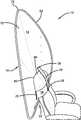
- FIG. 1is a first front view of a screen according to an exemplary embodiment of the present disclosure
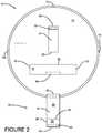
- FIG. 2is a second front view of the exemplary screen
- FIG. 3is a first perspective view of the exemplary screen in operation
- FIG. 4is a second perspective view of the exemplary screen in operation
- FIG. 5is a third perspective view of the exemplary screen in operation
- FIG. 6is a fourth perspective view of the exemplary screen
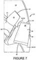
- FIG. 7is a fifth perspective view of the exemplary screen
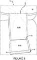
- FIG. 8is a sixth perspective view of the exemplary screen
- FIG. 9is a seventh perspective view of the exemplary screen.
- FIGS. 10A-10Care views of the exemplary screen being twice-folded
- FIG. 11is a side view of the exemplary screen when in operation
- FIG. 12is a side view of the exemplary screen when not in operation, but unfolded.
- FIG. 13is a rear view of the exemplary screen.
- the present disclosurecan provide an improved screen 10 for mounting on the back of a chair.
- D618,948is hereby incorporated in its entirety.
- the screen 10can conceal items positioned behind the chairback.
- the screen 10can include a primary panel 12 .
- the primary panel 12can have a front side 14 and a back side 16 .
- the exemplary primary panel 12extends laterally between first and second lateral edges 68 , 70 .
- the exemplary primary panel 12also extends vertically between top and bottom vertical edges 72 , 74 .
- the front side 14operable to confront and contact a back side 76 of a chairback 78 in operation.
- the primary panel 12is sized to extend beyond at least part of a perimeter 80 of the chairback 78 in operation to conceal items positioned behind the chairback 78 .
- the primary panel 12can be formed in part from foldable material such as fabric.
- the primary panel 12can also include a wire frame.
- the wire framecan be positioned in a pocket defined by the foldable material, as shown in FIG. 5 of D618,948, which is hereby incorporated by reference.
- the pocket and wire framecan extend about and define a perimeter 82 of the primary panel 12 .
- the primary panel 12can be folded for storage when not in use.
- FIG. 3shows the primary panel 12 in use.
- FIGS. 10A-10Cshow the screen 10 during the process of twice-folding.
- Axes 84 and 86are included in FIGS. 10A-10C for reference.
- the axis 86extends into and out of the page.
- FIGS. 10A and 10Care front views and FIG. 10B is a side view.
- the lateral edges 68 and 70can be brought together. This is shown in FIG. 10A .
- Thiscan cause the wire frame of the primary panel 12 to form the shape of the number eight.
- the usercan bring the top and bottom vertical edges 72 and 74 together.
- FIG. 10BThis can cause the wire frame of the primary panel 12 to form overlapping circles, shown in FIG. 10C .
- the screen 10can also include a horizontal strap 18 .
- the horizontal strap 18can extend between first and second ends 20 , 22 .
- the horizontal strap 18can be fixed to the front 14 of the primary panel 12 at the ends 20 , 22 , such as by sowing.
- the exemplary horizontal strap 18is configured to extend laterally around a front side of the chairback 78 in operation whereby the chairback 78 is positioned between the horizontal strap 18 and the primary panel 12 in operation.
- the horizontal strap 18can be formed from an elastic material so that, in operation, when the chairback 78 is positioned between the primary panel 12 and the horizontal strap 18 , the horizontal strap 18 is stretched.
- the screen 10can also include a vertical strap 24 .
- the vertical strap 24can extend between first and second ends 26 , 28 .
- the vertical strap 24can be fixed to the front 14 of the primary panel 12 at the end 26 , such as by sowing.
- the exemplary vertical strap 24is configured to extend vertically over a top 88 of the chairback 78 in operation whereby the top 88 of the chairback 78 is positioned between the vertical strap 24 and the primary panel 12 in operation.
- the vertical strap 24can be formed from elastic material whereby the vertical strap 24 is configured to elastically stretch around the top 88 of the chairback 78 in operation.
- the end 28can be releasably connectable to the horizontal strap 18 , such as with matching patches of hook and loop fasteners.
- a patch 30can be fixed on the end 28 and connect directly to the horizontal strap 18 .
- the vertical strap 24can be formed from a relatively non-elastic material so that, in operation, when the chairback 78 is positioned between the primary panel 12 and the vertical strap 24 , the vertical strap 24 inhibits the primary panel 12 from tipping backward.
- the screen 10can also include a brace assembly 32 .
- the brace assembly 32can further prevent the primary panel 12 from tipping backward.
- the exemplary brace assembly 32is configured to confront and contact the back side 76 of the chairback 78 in operation to urge the top vertical edge 72 forward.
- the exemplary brace assembly 32is fixed to the front side 14 at a first end 40 and extends to a second end 48 .
- the first end 40 of the exemplary brace assembly 32is fixed to the front side 14 at a first position closer to the bottom vertical edge 74 than the horizontal strap 18 .
- the second end 48is selectively engageable with the front side 14 at a second position spaced closer to the top vertical edge 72 than the first position.
- the exemplary second position at which the exemplary brace assembly 32 selectively connects to the primary exemplary panel 12is positioned between the primary exemplary panel 12 and the horizontal strap 18 (underneath the strap 18 ).
- the second end 48is engaged with the front side 14 in operation and disengaged from the front side 14 when not in operation.
- FIG. 6shows the exemplary brace assembly 32 laying on the horizontal strap 18 when not in operation
- FIG. 1shows the exemplary brace assembly 32 laying under the horizontal strap 18 when not in operation.
- the second end 48is closer to the top vertical edge 72 than the horizontal strap 18 when the exemplary brace assembly 32 is laying flat on the primary panel 12 and the primary panel 12 is unfolded, as shown in FIG. 1 .
- the exemplary brace assembly 32is configured to lay flat on the primary panel 12 when not in operation and defines a length when laying flat. In FIG. 1 , the length is defined along an axis extending between the top and bottom vertical edges 72 , 74 . As shown in FIG. 1 , the length of the exemplary brace assembly 32 is less than one-half a distance between the top vertical edge 72 and the bottom vertical edge 74 . This allows the brace assembly 32 to fit within the twice-folded primary panel 12 , enhancing the flatness of the screen 10 when stored.
- the first end of the vertical strap 24 and the first end of the exemplary brace assembly 32are positioned on opposite sides of the horizontal strap 18 .
- the primary panel 12is twice-foldable into a circular shape when not in operation.
- the exemplary brace assembly 32is sized to remain flat when the primary panel 12 has been twice-folded.
- the outline of the exemplary brace assembly 32is shown in phantom in FIG. 10C .
- the exemplary brace assembly 32is thus contained within a perimeter of the primary exemplary panel 12 when the primary exemplary panel 12 has been twice-folded.
- the exemplary brace assembly 32includes a plurality of panels or members pivotally interconnected to one another.
- the terms panel and memberare used interchangeably, but in other embodiments a member could be non-planar and/or non-cubic.
- the exemplary brace assembly 32includes a first exemplary panel 34 , a second exemplary panel 36 , and a third exemplary panel 38 .
- Each of the exemplary panels 34 , 36 , 38can be constructed generally similarly.
- Each of the exemplary panels 34 , 36 , 38can include a rigid plate enclosed by foldable material such as fabric.
- the first exemplary panel 34defines the first end 40 .
- the first exemplary panel 34can extend a first length between the first end 40 and an intermediate end 42 .
- the first exemplary panel 34can have an outer surface 44 and an inner surface 46 .
- the first exemplary panel 34can be fixed to the front 14 of the primary exemplary panel 12 at the end 40 , such as by sowing.
- the first exemplary panel 34is engaged with the primary exemplary panel 12 for pivoting movement about a first axis 94 , referenced in FIG. 1 .
- the second exemplary panel 36can extend between the end 42 and the end 48 .
- the second panel 36defines the second end 48 of the exemplary brace assembly 32 and extends a second length between the ends 42 and 48 .
- the second exemplary panel 36can have an outer surface 50 and an inner surface 52 .
- the second exemplary panel 36can be fixed to the first exemplary panel 34 at the end 42 , such as by sowing or by a common piece of flexible material containing both of the rigid plates that are components of the exemplary panels 34 , 36 .
- the exemplary end 42is a living hinge permitting freely-pivoting movement between the exemplary panels 34 and 36 .
- the third exemplary panel 38defines a substantially planar outer surface 58 configured to engage the back side 76 of the chairback 78 in operation.
- the third exemplary panel 38also defines “inner” surfaces 60 , 62 .
- the outer planar surface 58extends between panel edges 54 , 56 to define a height.
- the outer planar surface 58extends laterally between panel edges 90 , 92 to define a width.
- the third exemplary panel 38can be fixed to the first exemplary panel 34 and the second exemplary panel 36 at the end 42 , such as by sowing or by a common piece of flexible material containing all of the rigid plates that are parts of the exemplary panels 34 , 36 , 38 .
- the exemplary surfaces 60 , 62are similarly sized and are on opposite sides of the end 42 .
- the end 42can be a living hinge between all three exemplary panels 34 , 36 , 38 permitting freely-pivoting movement between the exemplary panels 34 , 36 and 38 .
- the first exemplary panel 34 and the second exemplary panel 36 and the third exemplary panel 38are thus pivotally interconnected to one another at a single living hinge.
- Each of the third exemplary panel 38 and the first exemplary panel 34 and the second exemplary panel 36are pivotal relative to the other two exemplary panels.
- the end/joint 42can be positioned midway between the ends 54 , 56 .
- the exemplary planar surface 58is operable to pivot in response to a configuration of the back side 76 of the chairback 78 to lie flush with the back side 76 of the chairback 78 .
- the third exemplary panel 38is engaged with the at least one of the first panel and the second panel for pivoting movement about an axis.
- the axis of pivoting movement of the panel 38is in a plane referenced by 96 in FIG. 1 .
- the perspective of FIG. 1is generally parallel to the plane of the surface 58 .
- the plane 96is normal to the surface 58 .
- the axis of pivoting movement of the panel 38is in the plane 96 , which is substantially centered between the panel edges 54 , 56 .
- the end 48can be releasably connectable to the primary exemplary panel 12 , such as with matching patches of hook and loop fasteners.
- a first patch 64can be fixed on the end 48 and releasibly connect to a second patch 66 at the second position on the primary exemplary panel 12 .
- the patch 66can be positioned under the horizontal strap 18 and is therefore shown in phantom in FIG. 2 .
- the usercan place the slip the screen 10 over the chairback 78 , wherein the chairback 78 passes in between the primary exemplary panel 12 and the horizontal strap 18 .
- the screen 10can be lowered over the back of the chair until the top-most edge 88 of the chairback 78 is positioned above the upper edge 98 of the horizontal strap 18 .
- the vertical strap 24is then extended over the top-most edge 88 of the chairback 78 and connected to the horizontal strap 18 .
- the exemplary second end 48can be releasably connected to the primary exemplary panel 12 , through the patches 64 , 66 .
- the outer surface 58 of the exemplary panel 38contacts the back surface 76 of the chairback 78 and can pivot to accommodate differently configured chairs.
- the exemplary panel 38does not contact the primary exemplary panel 12 when the exemplary brace assembly 32 is in operation.
- the exemplary panels 34 , 36do not contact the chairback 78 when the exemplary brace assembly 32 is in operation.
- the first panel 34 and the second panel 36are at angle of greater than zero degrees relative to one another when the second panel 36 is attached to the primary panel 12 at the second position.
- the exemplary panels 34 , 36define a V-shaped brace between the exemplary panel 38 and the primary exemplary panel 12 to support the exemplary panel 38 inhibit the primary exemplary panel 12 from tipping backward.
Landscapes
- Chair Legs, Seat Parts, And Backrests (AREA)
- Overhead Projectors And Projection Screens (AREA)
Abstract
Description
Claims (18)
Priority Applications (3)
| Application Number | Priority Date | Filing Date | Title |
|---|---|---|---|
| US16/001,040US10758053B2 (en) | 2017-12-12 | 2018-06-06 | Screen |
| CA3007525ACA3007525A1 (en) | 2017-12-12 | 2018-06-07 | Screen |
| US16/941,893US11229295B2 (en) | 2017-12-12 | 2020-07-29 | Screen |
Applications Claiming Priority (2)
| Application Number | Priority Date | Filing Date | Title |
|---|---|---|---|
| US201762597536P | 2017-12-12 | 2017-12-12 | |
| US16/001,040US10758053B2 (en) | 2017-12-12 | 2018-06-06 | Screen |
Related Child Applications (1)
| Application Number | Title | Priority Date | Filing Date |
|---|---|---|---|
| US16/941,893ContinuationUS11229295B2 (en) | 2017-12-12 | 2020-07-29 | Screen |
Publications (2)
| Publication Number | Publication Date |
|---|---|
| US20190174926A1 US20190174926A1 (en) | 2019-06-13 |
| US10758053B2true US10758053B2 (en) | 2020-09-01 |
Family
ID=66734487
Family Applications (2)
| Application Number | Title | Priority Date | Filing Date |
|---|---|---|---|
| US16/001,040Expired - Fee RelatedUS10758053B2 (en) | 2017-12-12 | 2018-06-06 | Screen |
| US16/941,893ActiveUS11229295B2 (en) | 2017-12-12 | 2020-07-29 | Screen |
Family Applications After (1)
| Application Number | Title | Priority Date | Filing Date |
|---|---|---|---|
| US16/941,893ActiveUS11229295B2 (en) | 2017-12-12 | 2020-07-29 | Screen |
Country Status (3)
| Country | Link |
|---|---|
| US (2) | US10758053B2 (en) |
| AU (1) | AU2018204214A1 (en) |
| CA (1) | CA3007525A1 (en) |
Cited By (3)
| Publication number | Priority date | Publication date | Assignee | Title |
|---|---|---|---|---|
| USD954783S1 (en)* | 2021-03-11 | 2022-06-14 | Zhihui ZHANG | Round folding backdrop |
| USD966748S1 (en)* | 2020-07-31 | 2022-10-18 | Daniel Jeremy SHATZKES | Screen for a chair |
| US12082709B2 (en)* | 2020-06-19 | 2024-09-10 | Gig Gear LLC | Chair-mountable screen |
Families Citing this family (1)
| Publication number | Priority date | Publication date | Assignee | Title |
|---|---|---|---|---|
| IT202100016205A1 (en)* | 2021-06-21 | 2022-12-21 | Officina Kreativa Srl | Home webcam background |
Citations (99)
| Publication number | Priority date | Publication date | Assignee | Title |
|---|---|---|---|---|
| US110844A (en)* | 1871-01-10 | Improvement in fire-screens and stands | ||
| US973936A (en)* | 1910-01-11 | 1910-10-25 | Willard Graves | Shield. |
| US2288469A (en) | 1939-11-04 | 1942-06-30 | Alex E Lookholder | Protecting cover for automobile seats and the like |
| US2349193A (en)* | 1941-09-13 | 1944-05-16 | Pass Sam | Furniture slip cover |
| US2557279A (en) | 1949-12-16 | 1951-06-19 | Harry Malter | Filter for vacuum cleaners |
| US2731997A (en)* | 1956-01-24 | Combined bag and flat cloth article | ||
| US2807315A (en)* | 1957-09-24 | Bookrack for connected seating | ||
| US2872242A (en)* | 1957-08-02 | 1959-02-03 | Gerald W Whartman | Insect deflector attachment for motor vehicles |
| US3329971A (en)* | 1965-03-15 | 1967-07-11 | Ted E Shelby | Combination leg protector and stadium seat |
| US3540775A (en)* | 1968-02-29 | 1970-11-17 | Max Defleur | Device for fastening objects to a seat |
| US4154478A (en)* | 1978-02-09 | 1979-05-15 | Cohune William H | Portable headrest |
| US4419982A (en)* | 1982-05-10 | 1983-12-13 | Eckels Robert E | Magnetic edge seal for solar collector film |
| US4639946A (en)* | 1985-10-03 | 1987-02-03 | Koenig Linda S | Restraining garment with detachable bib |
| US4676549A (en)* | 1986-03-28 | 1987-06-30 | Fashion Magic, Inc. | Seat cover |
| US4687248A (en)* | 1985-06-24 | 1987-08-18 | Tri-Rel, Inc. | Convertible lounge chair/tote bag |
| US4754987A (en)* | 1983-01-12 | 1988-07-05 | Williams Ronald H | Wheelchair |
| US4807929A (en)* | 1987-11-13 | 1989-02-28 | Balsbaugh Vernon L | Stackable chair with sliding compartment |
| US4823822A (en)* | 1988-02-24 | 1989-04-25 | Rachel Maya | Portable sun shade |
| US4960293A (en)* | 1989-05-02 | 1990-10-02 | Martin Bottinick | Animal shield |
| US5067770A (en)* | 1990-12-24 | 1991-11-26 | Hassell Jr Edwin | Sun shield for a childs car seat |
| US5075897A (en) | 1989-10-23 | 1991-12-31 | Daniels Victory A | Multi-purpose protective garment |
| US5131575A (en)* | 1989-12-19 | 1992-07-21 | Emilien Charest | Convertible chair and load carrier device |
| USD338779S (en)* | 1991-12-19 | 1993-08-31 | Albert Lonna R | Combined backpack and chair-pack |
| US5249592A (en)* | 1991-12-10 | 1993-10-05 | Springer Catherine P | Self-erecting tent |
| US5339748A (en) | 1993-08-09 | 1994-08-23 | Dayva International, Inc. | Table cover |
| US5393013A (en)* | 1991-12-17 | 1995-02-28 | Deutsche Aerospace Airbus Gmbh | Aircraft cabin dividing device |
| US5411318A (en)* | 1993-08-24 | 1995-05-02 | Law; Ignace K. | Extended ventilating seat covering assembly |
| US5544793A (en)* | 1995-03-28 | 1996-08-13 | Harrop; Kathy L. | Folding chair backpack |
| US5620040A (en)* | 1994-09-22 | 1997-04-15 | Performance Marketing, Inc. | Foldable cargo cover |
| US5652960A (en)* | 1996-04-16 | 1997-08-05 | Kaknevicius; Jurate T. | Nursing and stroller cover |
| US5666679A (en) | 1995-07-26 | 1997-09-16 | Ruddy; Gaila O. | Round blanket structure and method for making the same |
| US5690380A (en)* | 1996-08-23 | 1997-11-25 | Waters; Abby | Slipcovers with interchangeable trim |
| US5713624A (en)* | 1996-01-16 | 1998-02-03 | Creative Products & Trade, Inc. | Restraining net for car window |
| US5819999A (en)* | 1995-03-17 | 1998-10-13 | Tennant; Brian M. | Combination backpack and chair |
| US5860697A (en)* | 1995-06-23 | 1999-01-19 | Sebel Furniture Limited | School chair |
| USD411703S (en) | 1998-09-23 | 1999-06-29 | Rubbermaid Incorporated | Bath mat |
| US6022072A (en)* | 1998-04-02 | 2000-02-08 | Moyer; Lee Beth | Debris collector for upholstered furniture |
| USD425357S (en) | 1998-10-06 | 2000-05-23 | Gray Matter Holdings, Llc | Seat liner |
| USD428296S (en) | 1999-01-22 | 2000-07-18 | Kelldorf Mitchell T | Table cover |
| US6109282A (en)* | 1998-10-21 | 2000-08-29 | Yoon; Young W. | Self-erecting loop structure |
| US6145932A (en)* | 1994-04-19 | 2000-11-14 | Hamel-Nyhus; Paulette | Baby blanket with receiving compartment for use in car seat |
| US6170100B1 (en)* | 1998-05-19 | 2001-01-09 | Gray Matter Holdings, Llc | Self-opening towel |
| US6178979B1 (en) | 1998-12-16 | 2001-01-30 | Sandra L. Galloway | Table screen |
| US6216927B1 (en)* | 1998-08-03 | 2001-04-17 | Ronald Meritt | Mounting system for releasably and securely mounting an entertainment accessory within an automobile |
| US6296002B1 (en)* | 2000-03-20 | 2001-10-02 | Minas Tashchyan | Lightweight collapsible enclosure |
| US6447059B1 (en)* | 2000-08-03 | 2002-09-10 | Usa Products | Adjustable seat covers for high or low back seats |
| US6652026B2 (en)* | 1999-04-06 | 2003-11-25 | David K. Toyota | Headrest secured automobile seat cover |
| US6655731B2 (en)* | 2001-09-26 | 2003-12-02 | Charles N. Martin | Therapeutic chair |
| US6755232B1 (en)* | 2000-06-26 | 2004-06-29 | Jhrg, Llc | Fabric closure for open-end cargo containers |
| US6764133B2 (en)* | 2001-03-29 | 2004-07-20 | Combi International Corporation | Audio system for canopies used with strollers or rockers |
| USD496322S1 (en) | 2004-02-14 | 2004-09-21 | Dennis W. Farney | Automotive protective pad |
| US6823883B1 (en)* | 2002-10-24 | 2004-11-30 | Keith Sears | Collapsible, self-supporting, portable sun-screen apparatus |
| US6827262B2 (en)* | 2002-08-08 | 2004-12-07 | Hart Intercivic | Portable voting booth |
| US20040251717A1 (en)* | 2002-05-24 | 2004-12-16 | Yoshiaki Tamura | Suitcase with foldable chair |
| US6848460B2 (en)* | 2002-03-06 | 2005-02-01 | Patent Category Corp. | Collapsible sleeping structures |
| US7011367B2 (en)* | 2004-02-11 | 2006-03-14 | Prescient Partners, Lp | Universally adjustable slipcover for dining room chairs |
| USD530559S1 (en) | 2003-09-17 | 2006-10-24 | Jennifer Lee Fails | Infant carrier cover |
| USD545106S1 (en) | 2005-06-07 | 2007-06-26 | Cynthia Hourihan | Table cover |
| USD553894S1 (en)* | 2005-01-08 | 2007-10-30 | Springer Sharon A | Two piece chair slip cover |
| US7302957B2 (en)* | 2003-06-17 | 2007-12-04 | Ross Timmy L | Self-erecting and collapsible shade device |
| US7322626B2 (en)* | 2003-06-20 | 2008-01-29 | Colin Thomas | Vehicle drive security screen |
| USD575568S1 (en) | 2008-01-07 | 2008-08-26 | David Chen | Headrest cover |
| US7427101B1 (en)* | 2005-04-18 | 2008-09-23 | Nature Vision, Inc. | Chair shelter |
| US7446823B2 (en)* | 2004-09-08 | 2008-11-04 | Edward Zheng | Foldable mobile video device |
| USD603201S1 (en) | 2009-05-28 | 2009-11-03 | Corle Debra J | Sanitary headrest cover |
| US7644984B2 (en)* | 2008-01-10 | 2010-01-12 | Toyota Motor Engineering & Manufacturing North America, Inc. | Side shield for motor vehicle seat assembly |
| US7686392B2 (en)* | 2005-08-02 | 2010-03-30 | Shell Oil Company | Vehicle seat cover |
| USD618948S1 (en) | 2009-09-29 | 2010-07-06 | Bobachi, L.L.C. | Screen |
| US7810880B2 (en)* | 2003-07-31 | 2010-10-12 | Spellman Edward F | Vehicle seat mount equipment rack |
| US7891733B1 (en)* | 2009-03-23 | 2011-02-22 | Christopher Shay Clarke | Original backseat plan holder |
| US7896433B2 (en)* | 2003-07-28 | 2011-03-01 | Grammer Ag | Sitting arrangement for automotive vehicles |
| USD634152S1 (en) | 2010-10-16 | 2011-03-15 | Sandy Natkin | Airline seat cover |
| USD648588S1 (en) | 2011-01-31 | 2011-11-15 | Melissa Rice Golin | Convertible seat cover with top transparent section |
| USD648590S1 (en) | 2011-01-31 | 2011-11-15 | Melissa Rice Golin | Convertible seat cover with transparent section |
| USD648587S1 (en) | 2011-01-31 | 2011-11-15 | Melissa Rice Golin | Convertible seat cover |
| USD648589S1 (en) | 2011-01-31 | 2011-11-15 | Melissa Rice Golin | Convertible seat cover with corner transparent section |
| US8186755B2 (en)* | 2008-10-24 | 2012-05-29 | Bravo Sports | Collapsible canopy along with article of furniture and method incorporating the same |
| USD661937S1 (en) | 2011-07-11 | 2012-06-19 | Melissa Rice Golin | Convertible seat cover with upper transparent section |
| US8342226B2 (en)* | 2010-09-23 | 2013-01-01 | Patent Category Corp. | Collapsible sunshade |
| USD673803S1 (en) | 2012-06-29 | 2013-01-08 | Paron Todd C | Multi-media headrest holder |
| USD675469S1 (en) | 2011-09-22 | 2013-02-05 | Glowner Christina L | Seat cover |
| US8434805B1 (en)* | 2011-09-23 | 2013-05-07 | Harry F. Bonniville | Protective shield for a bus driver |
| US8500199B2 (en)* | 2004-04-01 | 2013-08-06 | Victoria Paulin | Disposable chair covers |
| US8534755B2 (en)* | 2009-11-30 | 2013-09-17 | Michael Nickerson | Detachable chair cushion and backpack assembly |
| US8556337B1 (en)* | 2009-07-02 | 2013-10-15 | Tammy L. Cornitius-Cary | Thermal cooling/heating seat/backrest cover |
| USD700460S1 (en) | 2013-01-04 | 2014-03-04 | Linda Bovay | Screen |
| US8708027B2 (en)* | 2006-09-05 | 2014-04-29 | Atmosphere Creative Inc. | Portable privacy shield for an automobile |
| US8746790B2 (en)* | 2006-10-07 | 2014-06-10 | Leisureease, LLC. | Apparatus that attaches to a chair to provide storage or to assist with chair transportation |
| US20140311036A1 (en) | 2013-03-15 | 2014-10-23 | Herman Miller, Inc. | Screen assembly |
| US9108733B2 (en)* | 2010-09-10 | 2015-08-18 | Panasonic Avionics Corporation | Integrated user interface system and method |
| USD737600S1 (en) | 2013-11-05 | 2015-09-01 | Linda Bovay | Screen |
| US20160090029A1 (en)* | 2014-09-25 | 2016-03-31 | Andrei LEVYTSKY | Safety banner |
| US9322197B2 (en)* | 2004-09-23 | 2016-04-26 | Keith D. Squires | Prisoner safety seat and method of use |
| US9383113B1 (en)* | 2015-07-28 | 2016-07-05 | Catherine Renwick | Detachable hood for a chair |
| US9516950B1 (en)* | 2013-02-04 | 2016-12-13 | Cathryn A. Osweiler | Electrically integrated salon styling chair with ergonomic equipment caddy |
| US9797157B2 (en)* | 2014-03-04 | 2017-10-24 | Shelterlogic Corp. | Canopy with detachable awning |
| US9814315B2 (en)* | 2013-02-04 | 2017-11-14 | Cathryn A Osweiler | Electrically integrated salon styling chair with ergonomic equipment caddy |
| US9930434B2 (en)* | 2012-10-25 | 2018-03-27 | Domash Design Source LLC | Visual and/or acoustic privacy features |
| US10575658B2 (en)* | 2017-03-29 | 2020-03-03 | East Babies, L.L.C. | Adjustable child restraint device |
Family Cites Families (30)
| Publication number | Priority date | Publication date | Assignee | Title |
|---|---|---|---|---|
| US1915504A (en)* | 1930-12-02 | 1933-06-27 | Lido Folding Rest Company Inc | Folding chair |
| US2990008A (en)* | 1958-12-22 | 1961-06-27 | Jack M Bien | Head and back rest |
| US3172702A (en)* | 1963-01-24 | 1965-03-09 | Rose Mfg Company | Safety head rest |
| US3645556A (en)* | 1968-12-18 | 1972-02-29 | Gic Kk | Safety net pillow for vehicle passengers |
| US3580633A (en)* | 1969-05-09 | 1971-05-25 | Florence Du Priest | Stadium foot bag and seat |
| US3848921A (en)* | 1973-04-02 | 1974-11-19 | R Rhodes | Boat seat |
| US4440443A (en)* | 1981-04-10 | 1984-04-03 | Nordskog Robert A | Headrest |
| US4597608A (en)* | 1985-08-05 | 1986-07-01 | Duffy Lavern N | Automobile windshield cover |
| US5154473A (en)* | 1990-05-22 | 1992-10-13 | Joranco Charles T | Chair with sun screen and windbreaker panel |
| US5203363A (en)* | 1991-05-13 | 1993-04-20 | William Kidwell | Portable canopy attachment |
| GB2269744B (en)* | 1992-08-19 | 1996-05-15 | Rory Michael Roe | A device for displacing a shower curtain to increase the volume of the shower area |
| US5524694A (en)* | 1994-09-21 | 1996-06-11 | H. G. Maybeck Co., Inc. | Protective screen for vehicle window |
| DE19536552C2 (en)* | 1995-09-29 | 2000-05-25 | Daimler Chrysler Ag | Wind deflector for a convertible with at least one roll bar |
| WO2000003926A1 (en)* | 1998-07-15 | 2000-01-27 | Darlene Strevey | Multi-purpose foldable tote bag |
| US6698828B1 (en)* | 2002-03-15 | 2004-03-02 | Portfolio Productions, Inc. | Folding chair |
| US6170680B1 (en)* | 1999-10-14 | 2001-01-09 | Chih-Chiang Hung | Rack for holding hairdressing tools |
| DE10024367A1 (en)* | 2000-05-17 | 2001-11-29 | I2S Interactive & Intelligent | Setdown screen plate and anchor comprises elastic plate bent between clipped ends and held thus by tensioner rope secured to plate and foot part anchorage. |
| US6695373B1 (en)* | 2002-07-11 | 2004-02-24 | Karen Meise | Transparent auto headrest |
| US20090151827A1 (en)* | 2007-12-17 | 2009-06-18 | Kevin Thompson | Removable protective cover door guard |
| US20090184077A1 (en)* | 2008-01-23 | 2009-07-23 | Daniel Curet | Styling station |
| IL191961A (en)* | 2008-06-05 | 2013-05-30 | Duff Adler | Personal protection apparatus for vehicles |
| US8167367B1 (en)* | 2010-08-19 | 2012-05-01 | Henry Martinez | Seat cover with adjustable cushion apparatus |
| US8517462B2 (en)* | 2011-05-24 | 2013-08-27 | Multiseat, Inc. | Configurable seating device and method of use thereof |
| US9493963B2 (en)* | 2013-09-17 | 2016-11-15 | Shadiant, Llc | Portable barrier and associated method of use |
| US9936811B2 (en)* | 2014-04-04 | 2018-04-10 | Ronald L. Rowe, JR. | Portable seat awning |
| US20140290879A1 (en)* | 2014-05-01 | 2014-10-02 | Inventu Research Inc. | Chair's backrest folding screen device |
| US9390571B1 (en)* | 2014-06-18 | 2016-07-12 | Benjamin Z. Kupfer | Chair with storage and charging capabilities |
| US9445672B2 (en)* | 2014-12-04 | 2016-09-20 | Nirva Demosthene | Portable seat cover device |
| US11039698B2 (en)* | 2017-05-13 | 2021-06-22 | Rekemo Chantal Fung-A-Wing | Portable and collapsible privacy shield |
| US11166564B2 (en)* | 2017-11-28 | 2021-11-09 | Wisconsin Alumni Research Foundation | Ergonomically configured muscle release office chair |
- 2018
- 2018-06-06USUS16/001,040patent/US10758053B2/ennot_activeExpired - Fee Related
- 2018-06-07CACA3007525Apatent/CA3007525A1/ennot_activeAbandoned
- 2018-06-13AUAU2018204214Apatent/AU2018204214A1/ennot_activeAbandoned
- 2020
- 2020-07-29USUS16/941,893patent/US11229295B2/enactiveActive
Patent Citations (99)
| Publication number | Priority date | Publication date | Assignee | Title |
|---|---|---|---|---|
| US2731997A (en)* | 1956-01-24 | Combined bag and flat cloth article | ||
| US110844A (en)* | 1871-01-10 | Improvement in fire-screens and stands | ||
| US2807315A (en)* | 1957-09-24 | Bookrack for connected seating | ||
| US973936A (en)* | 1910-01-11 | 1910-10-25 | Willard Graves | Shield. |
| US2288469A (en) | 1939-11-04 | 1942-06-30 | Alex E Lookholder | Protecting cover for automobile seats and the like |
| US2349193A (en)* | 1941-09-13 | 1944-05-16 | Pass Sam | Furniture slip cover |
| US2557279A (en) | 1949-12-16 | 1951-06-19 | Harry Malter | Filter for vacuum cleaners |
| US2872242A (en)* | 1957-08-02 | 1959-02-03 | Gerald W Whartman | Insect deflector attachment for motor vehicles |
| US3329971A (en)* | 1965-03-15 | 1967-07-11 | Ted E Shelby | Combination leg protector and stadium seat |
| US3540775A (en)* | 1968-02-29 | 1970-11-17 | Max Defleur | Device for fastening objects to a seat |
| US4154478A (en)* | 1978-02-09 | 1979-05-15 | Cohune William H | Portable headrest |
| US4419982A (en)* | 1982-05-10 | 1983-12-13 | Eckels Robert E | Magnetic edge seal for solar collector film |
| US4754987A (en)* | 1983-01-12 | 1988-07-05 | Williams Ronald H | Wheelchair |
| US4687248A (en)* | 1985-06-24 | 1987-08-18 | Tri-Rel, Inc. | Convertible lounge chair/tote bag |
| US4639946A (en)* | 1985-10-03 | 1987-02-03 | Koenig Linda S | Restraining garment with detachable bib |
| US4676549A (en)* | 1986-03-28 | 1987-06-30 | Fashion Magic, Inc. | Seat cover |
| US4807929A (en)* | 1987-11-13 | 1989-02-28 | Balsbaugh Vernon L | Stackable chair with sliding compartment |
| US4823822A (en)* | 1988-02-24 | 1989-04-25 | Rachel Maya | Portable sun shade |
| US4960293A (en)* | 1989-05-02 | 1990-10-02 | Martin Bottinick | Animal shield |
| US5075897A (en) | 1989-10-23 | 1991-12-31 | Daniels Victory A | Multi-purpose protective garment |
| US5131575A (en)* | 1989-12-19 | 1992-07-21 | Emilien Charest | Convertible chair and load carrier device |
| US5067770A (en)* | 1990-12-24 | 1991-11-26 | Hassell Jr Edwin | Sun shield for a childs car seat |
| US5249592A (en)* | 1991-12-10 | 1993-10-05 | Springer Catherine P | Self-erecting tent |
| US5393013A (en)* | 1991-12-17 | 1995-02-28 | Deutsche Aerospace Airbus Gmbh | Aircraft cabin dividing device |
| USD338779S (en)* | 1991-12-19 | 1993-08-31 | Albert Lonna R | Combined backpack and chair-pack |
| US5339748A (en) | 1993-08-09 | 1994-08-23 | Dayva International, Inc. | Table cover |
| US5411318A (en)* | 1993-08-24 | 1995-05-02 | Law; Ignace K. | Extended ventilating seat covering assembly |
| US6145932A (en)* | 1994-04-19 | 2000-11-14 | Hamel-Nyhus; Paulette | Baby blanket with receiving compartment for use in car seat |
| US5620040A (en)* | 1994-09-22 | 1997-04-15 | Performance Marketing, Inc. | Foldable cargo cover |
| US5819999A (en)* | 1995-03-17 | 1998-10-13 | Tennant; Brian M. | Combination backpack and chair |
| US5544793A (en)* | 1995-03-28 | 1996-08-13 | Harrop; Kathy L. | Folding chair backpack |
| US5860697A (en)* | 1995-06-23 | 1999-01-19 | Sebel Furniture Limited | School chair |
| US5666679A (en) | 1995-07-26 | 1997-09-16 | Ruddy; Gaila O. | Round blanket structure and method for making the same |
| US5713624A (en)* | 1996-01-16 | 1998-02-03 | Creative Products & Trade, Inc. | Restraining net for car window |
| US5652960A (en)* | 1996-04-16 | 1997-08-05 | Kaknevicius; Jurate T. | Nursing and stroller cover |
| US5690380A (en)* | 1996-08-23 | 1997-11-25 | Waters; Abby | Slipcovers with interchangeable trim |
| US6022072A (en)* | 1998-04-02 | 2000-02-08 | Moyer; Lee Beth | Debris collector for upholstered furniture |
| US6170100B1 (en)* | 1998-05-19 | 2001-01-09 | Gray Matter Holdings, Llc | Self-opening towel |
| US6216927B1 (en)* | 1998-08-03 | 2001-04-17 | Ronald Meritt | Mounting system for releasably and securely mounting an entertainment accessory within an automobile |
| USD411703S (en) | 1998-09-23 | 1999-06-29 | Rubbermaid Incorporated | Bath mat |
| USD425357S (en) | 1998-10-06 | 2000-05-23 | Gray Matter Holdings, Llc | Seat liner |
| US6109282A (en)* | 1998-10-21 | 2000-08-29 | Yoon; Young W. | Self-erecting loop structure |
| US6178979B1 (en) | 1998-12-16 | 2001-01-30 | Sandra L. Galloway | Table screen |
| USD428296S (en) | 1999-01-22 | 2000-07-18 | Kelldorf Mitchell T | Table cover |
| US6652026B2 (en)* | 1999-04-06 | 2003-11-25 | David K. Toyota | Headrest secured automobile seat cover |
| US6296002B1 (en)* | 2000-03-20 | 2001-10-02 | Minas Tashchyan | Lightweight collapsible enclosure |
| US6755232B1 (en)* | 2000-06-26 | 2004-06-29 | Jhrg, Llc | Fabric closure for open-end cargo containers |
| US6447059B1 (en)* | 2000-08-03 | 2002-09-10 | Usa Products | Adjustable seat covers for high or low back seats |
| US6764133B2 (en)* | 2001-03-29 | 2004-07-20 | Combi International Corporation | Audio system for canopies used with strollers or rockers |
| US6655731B2 (en)* | 2001-09-26 | 2003-12-02 | Charles N. Martin | Therapeutic chair |
| US6848460B2 (en)* | 2002-03-06 | 2005-02-01 | Patent Category Corp. | Collapsible sleeping structures |
| US20040251717A1 (en)* | 2002-05-24 | 2004-12-16 | Yoshiaki Tamura | Suitcase with foldable chair |
| US6827262B2 (en)* | 2002-08-08 | 2004-12-07 | Hart Intercivic | Portable voting booth |
| US6823883B1 (en)* | 2002-10-24 | 2004-11-30 | Keith Sears | Collapsible, self-supporting, portable sun-screen apparatus |
| US7302957B2 (en)* | 2003-06-17 | 2007-12-04 | Ross Timmy L | Self-erecting and collapsible shade device |
| US7322626B2 (en)* | 2003-06-20 | 2008-01-29 | Colin Thomas | Vehicle drive security screen |
| US7896433B2 (en)* | 2003-07-28 | 2011-03-01 | Grammer Ag | Sitting arrangement for automotive vehicles |
| US7810880B2 (en)* | 2003-07-31 | 2010-10-12 | Spellman Edward F | Vehicle seat mount equipment rack |
| USD530559S1 (en) | 2003-09-17 | 2006-10-24 | Jennifer Lee Fails | Infant carrier cover |
| US7011367B2 (en)* | 2004-02-11 | 2006-03-14 | Prescient Partners, Lp | Universally adjustable slipcover for dining room chairs |
| USD496322S1 (en) | 2004-02-14 | 2004-09-21 | Dennis W. Farney | Automotive protective pad |
| US8500199B2 (en)* | 2004-04-01 | 2013-08-06 | Victoria Paulin | Disposable chair covers |
| US7446823B2 (en)* | 2004-09-08 | 2008-11-04 | Edward Zheng | Foldable mobile video device |
| US9322197B2 (en)* | 2004-09-23 | 2016-04-26 | Keith D. Squires | Prisoner safety seat and method of use |
| USD553894S1 (en)* | 2005-01-08 | 2007-10-30 | Springer Sharon A | Two piece chair slip cover |
| US7427101B1 (en)* | 2005-04-18 | 2008-09-23 | Nature Vision, Inc. | Chair shelter |
| USD545106S1 (en) | 2005-06-07 | 2007-06-26 | Cynthia Hourihan | Table cover |
| US7686392B2 (en)* | 2005-08-02 | 2010-03-30 | Shell Oil Company | Vehicle seat cover |
| US8708027B2 (en)* | 2006-09-05 | 2014-04-29 | Atmosphere Creative Inc. | Portable privacy shield for an automobile |
| US8746790B2 (en)* | 2006-10-07 | 2014-06-10 | Leisureease, LLC. | Apparatus that attaches to a chair to provide storage or to assist with chair transportation |
| USD575568S1 (en) | 2008-01-07 | 2008-08-26 | David Chen | Headrest cover |
| US7644984B2 (en)* | 2008-01-10 | 2010-01-12 | Toyota Motor Engineering & Manufacturing North America, Inc. | Side shield for motor vehicle seat assembly |
| US8186755B2 (en)* | 2008-10-24 | 2012-05-29 | Bravo Sports | Collapsible canopy along with article of furniture and method incorporating the same |
| US7891733B1 (en)* | 2009-03-23 | 2011-02-22 | Christopher Shay Clarke | Original backseat plan holder |
| USD603201S1 (en) | 2009-05-28 | 2009-11-03 | Corle Debra J | Sanitary headrest cover |
| US8556337B1 (en)* | 2009-07-02 | 2013-10-15 | Tammy L. Cornitius-Cary | Thermal cooling/heating seat/backrest cover |
| USD618948S1 (en) | 2009-09-29 | 2010-07-06 | Bobachi, L.L.C. | Screen |
| US8534755B2 (en)* | 2009-11-30 | 2013-09-17 | Michael Nickerson | Detachable chair cushion and backpack assembly |
| US9108733B2 (en)* | 2010-09-10 | 2015-08-18 | Panasonic Avionics Corporation | Integrated user interface system and method |
| US8342226B2 (en)* | 2010-09-23 | 2013-01-01 | Patent Category Corp. | Collapsible sunshade |
| USD634152S1 (en) | 2010-10-16 | 2011-03-15 | Sandy Natkin | Airline seat cover |
| USD648589S1 (en) | 2011-01-31 | 2011-11-15 | Melissa Rice Golin | Convertible seat cover with corner transparent section |
| USD648587S1 (en) | 2011-01-31 | 2011-11-15 | Melissa Rice Golin | Convertible seat cover |
| USD648590S1 (en) | 2011-01-31 | 2011-11-15 | Melissa Rice Golin | Convertible seat cover with transparent section |
| USD648588S1 (en) | 2011-01-31 | 2011-11-15 | Melissa Rice Golin | Convertible seat cover with top transparent section |
| USD661937S1 (en) | 2011-07-11 | 2012-06-19 | Melissa Rice Golin | Convertible seat cover with upper transparent section |
| USD675469S1 (en) | 2011-09-22 | 2013-02-05 | Glowner Christina L | Seat cover |
| US8434805B1 (en)* | 2011-09-23 | 2013-05-07 | Harry F. Bonniville | Protective shield for a bus driver |
| USD673803S1 (en) | 2012-06-29 | 2013-01-08 | Paron Todd C | Multi-media headrest holder |
| US9930434B2 (en)* | 2012-10-25 | 2018-03-27 | Domash Design Source LLC | Visual and/or acoustic privacy features |
| USD700460S1 (en) | 2013-01-04 | 2014-03-04 | Linda Bovay | Screen |
| US9516950B1 (en)* | 2013-02-04 | 2016-12-13 | Cathryn A. Osweiler | Electrically integrated salon styling chair with ergonomic equipment caddy |
| US9814315B2 (en)* | 2013-02-04 | 2017-11-14 | Cathryn A Osweiler | Electrically integrated salon styling chair with ergonomic equipment caddy |
| US20140311036A1 (en) | 2013-03-15 | 2014-10-23 | Herman Miller, Inc. | Screen assembly |
| USD737600S1 (en) | 2013-11-05 | 2015-09-01 | Linda Bovay | Screen |
| US9797157B2 (en)* | 2014-03-04 | 2017-10-24 | Shelterlogic Corp. | Canopy with detachable awning |
| US20160090029A1 (en)* | 2014-09-25 | 2016-03-31 | Andrei LEVYTSKY | Safety banner |
| US9383113B1 (en)* | 2015-07-28 | 2016-07-05 | Catherine Renwick | Detachable hood for a chair |
| US10575658B2 (en)* | 2017-03-29 | 2020-03-03 | East Babies, L.L.C. | Adjustable child restraint device |
Cited By (3)
| Publication number | Priority date | Publication date | Assignee | Title |
|---|---|---|---|---|
| US12082709B2 (en)* | 2020-06-19 | 2024-09-10 | Gig Gear LLC | Chair-mountable screen |
| USD966748S1 (en)* | 2020-07-31 | 2022-10-18 | Daniel Jeremy SHATZKES | Screen for a chair |
| USD954783S1 (en)* | 2021-03-11 | 2022-06-14 | Zhihui ZHANG | Round folding backdrop |
Also Published As
| Publication number | Publication date |
|---|---|
| CA3007525A1 (en) | 2019-06-12 |
| AU2018204214A1 (en) | 2019-06-27 |
| US20200352339A1 (en) | 2020-11-12 |
| US20190174926A1 (en) | 2019-06-13 |
| US11229295B2 (en) | 2022-01-25 |
Similar Documents
| Publication | Publication Date | Title |
|---|---|---|
| US11229295B2 (en) | Screen | |
| USD899117S1 (en) | Folding stool | |
| EP1906795B1 (en) | Canopy chair | |
| US20200060420A1 (en) | Adjustable folding stand for a portable electronic device | |
| US8408145B2 (en) | Linked structure for foldable table | |
| US11490738B2 (en) | Electrical bed | |
| EP1055404A3 (en) | A walker | |
| US9062819B1 (en) | Collapsible computer laptop table | |
| US9907395B2 (en) | Hinge member and foldable structure incorporating the same | |
| US20150282624A1 (en) | Collapsible Chair and Method of Adjusting the Same | |
| CN202295883U (en) | Flat device protective sleeve capable of finely adjusting supporting angle | |
| CN205321513U (en) | Laptop computer knapsack | |
| CN205321515U (en) | Standable uses knapsack of laptop computer | |
| US20170023765A1 (en) | Portable visualization devices | |
| US1389700A (en) | Book-support | |
| USD477922S1 (en) | Webbed hunter's seat with folding length-adjustable legs | |
| WO2006113273A3 (en) | Pop-up bag stuffer | |
| USD902619S1 (en) | Portable folding beach chair | |
| KR200455249Y1 (en) | Articulated folding chair with reversible seat | |
| US20180206645A1 (en) | Portable hammock style chair | |
| US11950668B2 (en) | Convertible case for portable electronic device | |
| CN204467508U (en) | A kind of folding chair for rest | |
| CN205923532U (en) | Bed | |
| JP4324847B2 (en) | Simple table on the thigh | |
| KR102695899B1 (en) | An angle adjustable auxiliary desk |
Legal Events
| Date | Code | Title | Description |
|---|---|---|---|
| FEPP | Fee payment procedure | Free format text:ENTITY STATUS SET TO UNDISCOUNTED (ORIGINAL EVENT CODE: BIG.); ENTITY STATUS OF PATENT OWNER: SMALL ENTITY | |
| FEPP | Fee payment procedure | Free format text:ENTITY STATUS SET TO SMALL (ORIGINAL EVENT CODE: SMAL); ENTITY STATUS OF PATENT OWNER: SMALL ENTITY | |
| STPP | Information on status: patent application and granting procedure in general | Free format text:DOCKETED NEW CASE - READY FOR EXAMINATION | |
| STPP | Information on status: patent application and granting procedure in general | Free format text:NON FINAL ACTION MAILED | |
| STPP | Information on status: patent application and granting procedure in general | Free format text:RESPONSE TO NON-FINAL OFFICE ACTION ENTERED AND FORWARDED TO EXAMINER | |
| ZAAA | Notice of allowance and fees due | Free format text:ORIGINAL CODE: NOA | |
| ZAAB | Notice of allowance mailed | Free format text:ORIGINAL CODE: MN/=. | |
| STPP | Information on status: patent application and granting procedure in general | Free format text:PUBLICATIONS -- ISSUE FEE PAYMENT RECEIVED | |
| AS | Assignment | Owner name:WEBAROUND, LLC, MICHIGAN Free format text:CHANGE OF NAME;ASSIGNOR:BOBACHI, LLC;REEL/FRAME:053362/0758 Effective date:20200730 | |
| STCF | Information on status: patent grant | Free format text:PATENTED CASE | |
| FEPP | Fee payment procedure | Free format text:MAINTENANCE FEE REMINDER MAILED (ORIGINAL EVENT CODE: REM.); ENTITY STATUS OF PATENT OWNER: SMALL ENTITY | |
| LAPS | Lapse for failure to pay maintenance fees | Free format text:PATENT EXPIRED FOR FAILURE TO PAY MAINTENANCE FEES (ORIGINAL EVENT CODE: EXP.); ENTITY STATUS OF PATENT OWNER: SMALL ENTITY | |
| STCH | Information on status: patent discontinuation | Free format text:PATENT EXPIRED DUE TO NONPAYMENT OF MAINTENANCE FEES UNDER 37 CFR 1.362 | |
| FP | Lapsed due to failure to pay maintenance fee | Effective date:20240901 |