US10754036B2 - Scanning illuminated three-dimensional imaging systems - Google Patents
Scanning illuminated three-dimensional imaging systemsDownload PDFInfo
- Publication number
- US10754036B2 US10754036B2US15/389,368US201615389368AUS10754036B2US 10754036 B2US10754036 B2US 10754036B2US 201615389368 AUS201615389368 AUS 201615389368AUS 10754036 B2US10754036 B2US 10754036B2
- Authority
- US
- United States
- Prior art keywords
- light
- fan
- mirror
- dimensional imaging
- imaging system
- Prior art date
- Legal status (The legal status is an assumption and is not a legal conclusion. Google has not performed a legal analysis and makes no representation as to the accuracy of the status listed.)
- Active, expires
Links
Images


Classifications
- G—PHYSICS
- G01—MEASURING; TESTING
- G01S—RADIO DIRECTION-FINDING; RADIO NAVIGATION; DETERMINING DISTANCE OR VELOCITY BY USE OF RADIO WAVES; LOCATING OR PRESENCE-DETECTING BY USE OF THE REFLECTION OR RERADIATION OF RADIO WAVES; ANALOGOUS ARRANGEMENTS USING OTHER WAVES
- G01S17/00—Systems using the reflection or reradiation of electromagnetic waves other than radio waves, e.g. lidar systems
- G01S17/88—Lidar systems specially adapted for specific applications
- G01S17/89—Lidar systems specially adapted for specific applications for mapping or imaging
- B—PERFORMING OPERATIONS; TRANSPORTING
- B60—VEHICLES IN GENERAL
- B60R—VEHICLES, VEHICLE FITTINGS, OR VEHICLE PARTS, NOT OTHERWISE PROVIDED FOR
- B60R1/00—Optical viewing arrangements; Real-time viewing arrangements for drivers or passengers using optical image capturing systems, e.g. cameras or video systems specially adapted for use in or on vehicles
- B—PERFORMING OPERATIONS; TRANSPORTING
- B60—VEHICLES IN GENERAL
- B60R—VEHICLES, VEHICLE FITTINGS, OR VEHICLE PARTS, NOT OTHERWISE PROVIDED FOR
- B60R11/00—Arrangements for holding or mounting articles, not otherwise provided for
- B60R11/04—Mounting of cameras operative during drive; Arrangement of controls thereof relative to the vehicle
- G—PHYSICS
- G01—MEASURING; TESTING
- G01S—RADIO DIRECTION-FINDING; RADIO NAVIGATION; DETERMINING DISTANCE OR VELOCITY BY USE OF RADIO WAVES; LOCATING OR PRESENCE-DETECTING BY USE OF THE REFLECTION OR RERADIATION OF RADIO WAVES; ANALOGOUS ARRANGEMENTS USING OTHER WAVES
- G01S17/00—Systems using the reflection or reradiation of electromagnetic waves other than radio waves, e.g. lidar systems
- G01S17/02—Systems using the reflection of electromagnetic waves other than radio waves
- G01S17/06—Systems determining position data of a target
- G01S17/08—Systems determining position data of a target for measuring distance only
- G01S17/10—Systems determining position data of a target for measuring distance only using transmission of interrupted, pulse-modulated waves
- G—PHYSICS
- G01—MEASURING; TESTING
- G01S—RADIO DIRECTION-FINDING; RADIO NAVIGATION; DETERMINING DISTANCE OR VELOCITY BY USE OF RADIO WAVES; LOCATING OR PRESENCE-DETECTING BY USE OF THE REFLECTION OR RERADIATION OF RADIO WAVES; ANALOGOUS ARRANGEMENTS USING OTHER WAVES
- G01S17/00—Systems using the reflection or reradiation of electromagnetic waves other than radio waves, e.g. lidar systems
- G01S17/02—Systems using the reflection of electromagnetic waves other than radio waves
- G01S17/06—Systems determining position data of a target
- G01S17/42—Simultaneous measurement of distance and other co-ordinates
- G—PHYSICS
- G01—MEASURING; TESTING
- G01S—RADIO DIRECTION-FINDING; RADIO NAVIGATION; DETERMINING DISTANCE OR VELOCITY BY USE OF RADIO WAVES; LOCATING OR PRESENCE-DETECTING BY USE OF THE REFLECTION OR RERADIATION OF RADIO WAVES; ANALOGOUS ARRANGEMENTS USING OTHER WAVES
- G01S17/00—Systems using the reflection or reradiation of electromagnetic waves other than radio waves, e.g. lidar systems
- G01S17/87—Combinations of systems using electromagnetic waves other than radio waves
- G—PHYSICS
- G01—MEASURING; TESTING
- G01S—RADIO DIRECTION-FINDING; RADIO NAVIGATION; DETERMINING DISTANCE OR VELOCITY BY USE OF RADIO WAVES; LOCATING OR PRESENCE-DETECTING BY USE OF THE REFLECTION OR RERADIATION OF RADIO WAVES; ANALOGOUS ARRANGEMENTS USING OTHER WAVES
- G01S17/00—Systems using the reflection or reradiation of electromagnetic waves other than radio waves, e.g. lidar systems
- G01S17/88—Lidar systems specially adapted for specific applications
- G01S17/93—Lidar systems specially adapted for specific applications for anti-collision purposes
- G01S17/931—Lidar systems specially adapted for specific applications for anti-collision purposes of land vehicles
- G—PHYSICS
- G01—MEASURING; TESTING
- G01S—RADIO DIRECTION-FINDING; RADIO NAVIGATION; DETERMINING DISTANCE OR VELOCITY BY USE OF RADIO WAVES; LOCATING OR PRESENCE-DETECTING BY USE OF THE REFLECTION OR RERADIATION OF RADIO WAVES; ANALOGOUS ARRANGEMENTS USING OTHER WAVES
- G01S7/00—Details of systems according to groups G01S13/00, G01S15/00, G01S17/00
- G01S7/48—Details of systems according to groups G01S13/00, G01S15/00, G01S17/00 of systems according to group G01S17/00
- G01S7/481—Constructional features, e.g. arrangements of optical elements
- G01S7/4811—Constructional features, e.g. arrangements of optical elements common to transmitter and receiver
- G—PHYSICS
- G01—MEASURING; TESTING
- G01S—RADIO DIRECTION-FINDING; RADIO NAVIGATION; DETERMINING DISTANCE OR VELOCITY BY USE OF RADIO WAVES; LOCATING OR PRESENCE-DETECTING BY USE OF THE REFLECTION OR RERADIATION OF RADIO WAVES; ANALOGOUS ARRANGEMENTS USING OTHER WAVES
- G01S7/00—Details of systems according to groups G01S13/00, G01S15/00, G01S17/00
- G01S7/48—Details of systems according to groups G01S13/00, G01S15/00, G01S17/00 of systems according to group G01S17/00
- G01S7/481—Constructional features, e.g. arrangements of optical elements
- G01S7/4814—Constructional features, e.g. arrangements of optical elements of transmitters alone
- G01S7/4815—Constructional features, e.g. arrangements of optical elements of transmitters alone using multiple transmitters
- G—PHYSICS
- G01—MEASURING; TESTING
- G01S—RADIO DIRECTION-FINDING; RADIO NAVIGATION; DETERMINING DISTANCE OR VELOCITY BY USE OF RADIO WAVES; LOCATING OR PRESENCE-DETECTING BY USE OF THE REFLECTION OR RERADIATION OF RADIO WAVES; ANALOGOUS ARRANGEMENTS USING OTHER WAVES
- G01S7/00—Details of systems according to groups G01S13/00, G01S15/00, G01S17/00
- G01S7/48—Details of systems according to groups G01S13/00, G01S15/00, G01S17/00 of systems according to group G01S17/00
- G01S7/481—Constructional features, e.g. arrangements of optical elements
- G01S7/4816—Constructional features, e.g. arrangements of optical elements of receivers alone
- G—PHYSICS
- G01—MEASURING; TESTING
- G01S—RADIO DIRECTION-FINDING; RADIO NAVIGATION; DETERMINING DISTANCE OR VELOCITY BY USE OF RADIO WAVES; LOCATING OR PRESENCE-DETECTING BY USE OF THE REFLECTION OR RERADIATION OF RADIO WAVES; ANALOGOUS ARRANGEMENTS USING OTHER WAVES
- G01S7/00—Details of systems according to groups G01S13/00, G01S15/00, G01S17/00
- G01S7/48—Details of systems according to groups G01S13/00, G01S15/00, G01S17/00 of systems according to group G01S17/00
- G01S7/481—Constructional features, e.g. arrangements of optical elements
- G01S7/4817—Constructional features, e.g. arrangements of optical elements relating to scanning
- G—PHYSICS
- G01—MEASURING; TESTING
- G01S—RADIO DIRECTION-FINDING; RADIO NAVIGATION; DETERMINING DISTANCE OR VELOCITY BY USE OF RADIO WAVES; LOCATING OR PRESENCE-DETECTING BY USE OF THE REFLECTION OR RERADIATION OF RADIO WAVES; ANALOGOUS ARRANGEMENTS USING OTHER WAVES
- G01S7/00—Details of systems according to groups G01S13/00, G01S15/00, G01S17/00
- G01S7/48—Details of systems according to groups G01S13/00, G01S15/00, G01S17/00 of systems according to group G01S17/00
- G01S7/483—Details of pulse systems
- G01S7/484—Transmitters
- G—PHYSICS
- G01—MEASURING; TESTING
- G01S—RADIO DIRECTION-FINDING; RADIO NAVIGATION; DETERMINING DISTANCE OR VELOCITY BY USE OF RADIO WAVES; LOCATING OR PRESENCE-DETECTING BY USE OF THE REFLECTION OR RERADIATION OF RADIO WAVES; ANALOGOUS ARRANGEMENTS USING OTHER WAVES
- G01S7/00—Details of systems according to groups G01S13/00, G01S15/00, G01S17/00
- G01S7/48—Details of systems according to groups G01S13/00, G01S15/00, G01S17/00 of systems according to group G01S17/00
- G01S7/483—Details of pulse systems
- G01S7/486—Receivers
- G01S7/4865—Time delay measurement, e.g. time-of-flight measurement, time of arrival measurement or determining the exact position of a peak
- G—PHYSICS
- G01—MEASURING; TESTING
- G01S—RADIO DIRECTION-FINDING; RADIO NAVIGATION; DETERMINING DISTANCE OR VELOCITY BY USE OF RADIO WAVES; LOCATING OR PRESENCE-DETECTING BY USE OF THE REFLECTION OR RERADIATION OF RADIO WAVES; ANALOGOUS ARRANGEMENTS USING OTHER WAVES
- G01S7/00—Details of systems according to groups G01S13/00, G01S15/00, G01S17/00
- G01S7/48—Details of systems according to groups G01S13/00, G01S15/00, G01S17/00 of systems according to group G01S17/00
- G01S7/483—Details of pulse systems
- G01S7/486—Receivers
- G01S7/4868—Controlling received signal intensity or exposure of sensor
- G—PHYSICS
- G01—MEASURING; TESTING
- G01S—RADIO DIRECTION-FINDING; RADIO NAVIGATION; DETERMINING DISTANCE OR VELOCITY BY USE OF RADIO WAVES; LOCATING OR PRESENCE-DETECTING BY USE OF THE REFLECTION OR RERADIATION OF RADIO WAVES; ANALOGOUS ARRANGEMENTS USING OTHER WAVES
- G01S7/00—Details of systems according to groups G01S13/00, G01S15/00, G01S17/00
- G01S7/48—Details of systems according to groups G01S13/00, G01S15/00, G01S17/00 of systems according to group G01S17/00
- G01S7/497—Means for monitoring or calibrating
- G01S7/4972—Alignment of sensor
- G06K9/00805—
- G—PHYSICS
- G06—COMPUTING OR CALCULATING; COUNTING
- G06T—IMAGE DATA PROCESSING OR GENERATION, IN GENERAL
- G06T7/00—Image analysis
- G06T7/50—Depth or shape recovery
- G06T7/521—Depth or shape recovery from laser ranging, e.g. using interferometry; from the projection of structured light
- G—PHYSICS
- G06—COMPUTING OR CALCULATING; COUNTING
- G06T—IMAGE DATA PROCESSING OR GENERATION, IN GENERAL
- G06T7/00—Image analysis
- G06T7/70—Determining position or orientation of objects or cameras
- G—PHYSICS
- G06—COMPUTING OR CALCULATING; COUNTING
- G06V—IMAGE OR VIDEO RECOGNITION OR UNDERSTANDING
- G06V20/00—Scenes; Scene-specific elements
- G06V20/50—Context or environment of the image
- G06V20/56—Context or environment of the image exterior to a vehicle by using sensors mounted on the vehicle
- G06V20/58—Recognition of moving objects or obstacles, e.g. vehicles or pedestrians; Recognition of traffic objects, e.g. traffic signs, traffic lights or roads
- H—ELECTRICITY
- H04—ELECTRIC COMMUNICATION TECHNIQUE
- H04N—PICTORIAL COMMUNICATION, e.g. TELEVISION
- H04N13/00—Stereoscopic video systems; Multi-view video systems; Details thereof
- H04N13/20—Image signal generators
- H04N13/204—Image signal generators using stereoscopic image cameras
- H04N13/239—Image signal generators using stereoscopic image cameras using two 2D image sensors having a relative position equal to or related to the interocular distance
- H—ELECTRICITY
- H04—ELECTRIC COMMUNICATION TECHNIQUE
- H04N—PICTORIAL COMMUNICATION, e.g. TELEVISION
- H04N13/00—Stereoscopic video systems; Multi-view video systems; Details thereof
- H04N13/20—Image signal generators
- H04N13/204—Image signal generators using stereoscopic image cameras
- H04N13/254—Image signal generators using stereoscopic image cameras in combination with electromagnetic radiation sources for illuminating objects
- B—PERFORMING OPERATIONS; TRANSPORTING
- B60—VEHICLES IN GENERAL
- B60R—VEHICLES, VEHICLE FITTINGS, OR VEHICLE PARTS, NOT OTHERWISE PROVIDED FOR
- B60R11/00—Arrangements for holding or mounting articles, not otherwise provided for
- B60R2011/0001—Arrangements for holding or mounting articles, not otherwise provided for characterised by position
- B60R2011/004—Arrangements for holding or mounting articles, not otherwise provided for characterised by position outside the vehicle
- B—PERFORMING OPERATIONS; TRANSPORTING
- B60—VEHICLES IN GENERAL
- B60R—VEHICLES, VEHICLE FITTINGS, OR VEHICLE PARTS, NOT OTHERWISE PROVIDED FOR
- B60R2300/00—Details of viewing arrangements using cameras and displays, specially adapted for use in a vehicle
- B60R2300/10—Details of viewing arrangements using cameras and displays, specially adapted for use in a vehicle characterised by the type of camera system used
- B60R2300/103—Details of viewing arrangements using cameras and displays, specially adapted for use in a vehicle characterised by the type of camera system used using camera systems provided with artificial illumination device, e.g. IR light source
- B—PERFORMING OPERATIONS; TRANSPORTING
- B60—VEHICLES IN GENERAL
- B60R—VEHICLES, VEHICLE FITTINGS, OR VEHICLE PARTS, NOT OTHERWISE PROVIDED FOR
- B60R2300/00—Details of viewing arrangements using cameras and displays, specially adapted for use in a vehicle
- B60R2300/10—Details of viewing arrangements using cameras and displays, specially adapted for use in a vehicle characterised by the type of camera system used
- B60R2300/105—Details of viewing arrangements using cameras and displays, specially adapted for use in a vehicle characterised by the type of camera system used using multiple cameras
- B—PERFORMING OPERATIONS; TRANSPORTING
- B60—VEHICLES IN GENERAL
- B60R—VEHICLES, VEHICLE FITTINGS, OR VEHICLE PARTS, NOT OTHERWISE PROVIDED FOR
- B60R2300/00—Details of viewing arrangements using cameras and displays, specially adapted for use in a vehicle
- B60R2300/80—Details of viewing arrangements using cameras and displays, specially adapted for use in a vehicle characterised by the intended use of the viewing arrangement
- B60R2300/8093—Details of viewing arrangements using cameras and displays, specially adapted for use in a vehicle characterised by the intended use of the viewing arrangement for obstacle warning
Definitions
- Three-dimensional sensorsare important for autonomous vehicles, drones, and other applications. They may be used, for example, for obstacle detection in an autonomous vehicle.
- a conventional three-dimensional imaging systemmay include two cameras separated by a base distance. An object's images captured by the two cameras will display at different coordinates due to the lateral disparity. The object distance from the three-dimensional imaging system can be calculated with the image difference.
- the conventional three-dimensional imaging systemmay have a number of limitations. For example, if the object has no distinguishable features, identification of corresponding locations cannot be made. Also, if illumination is poor or is too strong such that it exceeds the dynamic range of the camera, the depth measurement can become unreliable.
- the measurement accuracymay be critically dependent on the image quality and the stability of baseline distance, both of which may be difficult to control, especially in automotive environment. Therefore, improved three-dimensional imaging systems are desired.
- a three-dimensional imaging systemincludes a first illumination source configured to project a first fan of light toward an object in a field of view.
- the first fan of lightmay generate a first illumination line as the first fan of light strikes the object.
- the three-dimensional imaging systemfurther includes a second illumination source configured to project a second fan of light substantially parallel to and spaced apart from the first fan of light.
- the second fan of lightmay generate a second illumination line as the second fan of light strikes the object.
- the first illumination source and the second illumination sourceare further configured to scan the first fan of light and the second fan of light synchronously laterally across the object.
- the three-dimensional imaging systemfurther includes a camera configured to capture a plurality of image frames of the field of view as the first fan of light and the second fan of light are scanned over a plurality of regions the object. Each image frame includes an image of the first illumination line and the second illumination line when the first fan of light and the second fan of light strike a respective region of the object.
- the three-dimensional imaging systemfurther includes a processor coupled to the camera and configured to construct a three-dimensional image of the object based on the plurality of image frames.
- a three-dimensional imaging systemincludes an illumination source configured to project a fan of light toward an object in a field of view.
- the fan of lightmay generate an illumination line as the fan of light strikes the object.
- the illumination sourceis further configured to scan the fan of light laterally across the field of view.
- the three-dimensional imaging systemfurther includes a first camera positioned laterally separated from the illumination source by a first baseline distance.
- the first camerais configured to capture a plurality of first image frames of the field of view as the fan of light is scanned over a plurality of regions of the object. Each first image frame includes an image of the illumination line when the fan of light strikes a respective region of the object.
- the three-dimensional imaging systemfurther includes a processor coupled to the first camera.
- the processoris configured to, for each of the plurality of first image frames, determine a position of the illumination line in the respective first image frame, and determine a distance from the three-dimensional imaging system to the respective region of the object corresponding to the respective first image frame based on the determined position.
- the processoris further configured to construct a three-dimensional image of the object based on a plurality of distances from the camera to the plurality of regions of the object determined from the plurality of first image frames.
- a three-dimensional imaging systemincludes a first illumination source configured to project a first structured illumination toward an object in a field of view.
- the first structure illuminationmay generate a first distorted illumination pattern as the first structure illumination strikes the object.
- the three-dimensional imaging systemfurther includes a second illumination source configured to project a second structured illumination toward the object in the field of view.
- the second structure illuminationmay generate a second distorted illumination pattern as the second structure illumination strikes the object.
- the three-dimensional imaging systemfurther includes a camera positioned laterally separated from the first illumination source by a first baseline distance and from the second illumination source by a second baseline distance.
- the camerais configured to capture an image frame of the field of view, the image frame including at least one of an image of the first distorted illumination pattern and an image of the second distorted illumination pattern.
- the three-dimensional imaging systemfurther includes a processor coupled to the camera and configured to construct a three-dimensional image of the object based on at least one of the image of the first distorted illumination pattern and the image of the second distorted illumination pattern.
- the first baseline distancemay be selected for a predetermined distance resolution
- the second baseline distancemay be selected for a predetermined distance detection range.
- the processoris further configured to construct a first three-dimensional image of the object based on the image of the first distorted illumination pattern, construct a second three-dimensional image of the object based on the image of the second distorted illumination pattern, and calibrate the first three-dimensional image of the object using the second three-dimensional image of the object to obtain the three-dimensional image of the object.
- the first illumination sourceincludes a first laser source configured to emit a first laser beam, and a first diffractive optical element configured to convert the first laser beam into the first structure illumination;
- the second illumination sourceincludes a second laser source configured to emit a second laser beam, and a second diffractive optical element configured to convert the second laser beam into the second structure illumination.
- the first structured illuminationhas a first pattern, and the second structure illumination has a second pattern different from the first pattern.
- the first illumination sourceis configured to modulate the first illumination pattern at a predetermined frequency
- the second illumination sourceis configured to modulate the second illumination pattern at the predetermined frequency but at an offset phase with respect to the first illumination pattern.
- FIG. 1illustrates schematically a conventional three-dimensional imaging system.
- FIG. 2illustrates schematically a three-dimensional imaging system according to an embodiment of the present invention.
- FIG. 3illustrates a three-dimensional imaging system according to another embodiment of the present invention.
- FIG. 4illustrates schematically an image of an object (e.g., a house) that may be captured by the camera of the three-dimensional imaging system illustrated in FIG. 3 according to an embodiment of the present invention.
- an objecte.g., a house
- FIG. 5shows a schematic plot of the light intensity at a pixel of an image sensor as a function of frame number according to an embodiment of the present invention.
- FIG. 6illustrates schematically a three-dimensional imaging system using scanning mirrors according to an embodiment of the present invention.
- FIG. 7illustrates schematically a three-dimensional imaging system using scanning mirrors according to another embodiment of the present invention.
- FIG. 8illustrates a three-dimensional imaging system according to another embodiment of the present invention.
- FIG. 9illustrates a three-dimensional imaging system according to another embodiment of the present invention.
- FIG. 10illustrates a three-dimensional imaging system according to yet another embodiment of the present invention.
- FIG. 11illustrates a three-dimensional imaging system according to another embodiment of the present invention.
- FIG. 12illustrates a three-dimensional imaging system that includes a scanning filter according to an embodiment of the present invention.
- FIG. 13illustrates schematically a three-dimensional imaging system using structured illumination according to an embodiment of the present invention.
- FIG. 14illustrates a three-dimensional imaging system using structured illumination according another embodiment of the present invention.
- FIG. 15illustrates schematically one or more three-dimensional imaging systems mounted on an autonomous or semi-autonomous vehicle for obstacle detection according to an embodiment of the present invention.
- FIG. 1illustrates schematically a conventional three-dimensional imaging system 100 , which includes a first camera 102 and a second camera 104 displaced laterally from one another with a baseline distance D.
- the first camera 102 and the second camera 104may be used to obtain a first image 142 and a second image 144 , respectively, of a scene 130 .
- An object 132 in the scenefor example a house, may appear at different image coordinates in the two images 142 and 144 due to parallax, in a manner similar to human binocular vision.
- the relative depth informationcan be obtained in the form of a disparity map, which encodes the difference in horizontal coordinates of corresponding image points.
- the values in this disparity mapmay be inversely proportional to the scene depth at the corresponding pixel location.
- depth information about the object 132 relative to the three-dimensional imaging system 100can be determined from the disparity map.
- the conventional three-dimensional imaging system 100 illustrated in FIG. 1may have a number of limitations. For example, if the object has no distinguishable features (i.e., texture-less or feature-less), then identification of corresponding locations cannot be made. As a result, depth information about the object cannot be extracted from the images. As another example, if illumination is poor or is too strong such that it exceeds the dynamic range of the camera, the depth measurement can become unreliable. Furthermore, if the object is located at a relatively long distance from the three-dimensional imaging system 100 compared to the baseline distance D, the measurement accuracy may be critically dependent on the image quality and the stability of baseline distance D, both of which may be difficult to control, especially in automotive environment. Embodiments of the present invention provide three-dimensional imaging systems that may overcome some of the above-mentioned limitations of a conventional three-dimensional imaging system.
- FIG. 2illustrates schematically a three-dimensional imaging system 200 for three-dimensional (3D) sensing according to an embodiment of the present invention.
- the three-dimensional imaging system 200includes a first camera 202 and a second camera 204 displaced horizontally from one another.
- the three-dimensional imaging system 200further includes an illumination source 220 configured to project a vertical fan of light 222 toward the scene in front of the two cameras 202 and 204 .
- the illumination source 220may comprise a laser source configured to emit a laser beam, and an optical element, such as a cylindrical lens, configured to convert the laser beam into the vertical fan of light 222 .
- the vertical fan of light 222may form an illumination line on an object as it strikes the object.
- the depth information about the object from the three-dimensional imaging system 200may be determined in the same fashion as in a conventional three-dimensional imaging system.
- An advantage of three-dimensional imaging system 200 as compared to a conventional three-dimensional imaging systemis that the illumination line serves as both the illumination and the feature for the cameras to detect, thus it can perform 3D sensing of objects even if the objects are feature-less and are under poor natural illumination.
- the illumination source 220may further include a scanning mechanism configured to scan the vertical fan of light 222 in the horizontal direction.
- the scanning mechanismmay comprise a scanning mirror or a rotating mirror.
- a flexure bearing or rotating bearingcan be used for scanning the mirror.
- the flexure bearing or rotating bearingcan be driven by a piezoelectric element, a voice coil actuator, or an electric motor according to various embodiments.
- the scanning mechanismmay comprise an acoustic optical deflector.
- the cameras 202 and 204may capture snap shots of the illumination line at a suitable frame rate, so that distance information about objects in the field of view may be obtained.
- the frame rate of the camerasmay be set for a desired horizontal spatial resolution and a desired detection rate.
- the frame ratemay range from about 30 frames per second to about 1,000 frames per second
- the illumination scan ratemay range from about 1 sweep per second to about 20 sweeps per second.
- the horizontal resolution and frame rate for a complete imagedepends on the scan rate of the illumination as well as the camera frame rate.
- each imagewill have 200 horizontal pixels, and the image rate will be 5 images per second.
- one imagemay be taken as the fan of light 222 scans from left to right, and the next image can be taken as the fan of light 222 scans back from right to left.
- a three-dimensional imaging systemmay include only one camera, instead of two cameras as illustrated in FIG. 2 .
- the axis of the camerais offset from the axis of the illumination source in the horizontal direction by a baseline distance, depth information about the objects in the field of view may be obtained from the distortions of the illumination line in the images based on a prior calibration using a known object.
- the illumination sourcemay be configured to project a horizontal fan of light onto the objects in front of the cameras.
- the horizontal fan of linemay be scanned in the vertical direction for 3D sensing the objects.
- the fan of lightcan be in other angles different from the horizontal or vertical.
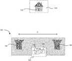
- FIG. 3illustrates a three-dimensional imaging system 300 according to another embodiment of the present invention.
- the three-dimensional imaging system 300includes one camera 302 and two illumination sources 310 and 320 .
- the two illumination sources 310 and 320are configured to project two vertical fans of light 312 and 322 .
- the two vertical fans of light 312 and 322may be adjusted to be parallel to each other.
- the three-dimensional imaging system 300may further include a scanning mechanism configured to scan the two vertical fans of light 312 and 322 in a horizontal direction simultaneously and synchronously.
- the scan mechanismmay comprise a scanning mirror or a rotating mirror, or an acoustic optical deflector, according to various embodiments of the present invention.
- the spatial resolution in the x-y plane and the depth accuracymay depend on the spacing between the two vertical fans of light 312 and 322 .
- the spacing between the two fans of light 312 and 322may be configured to be from about two inches to about two feet. In one embodiment, the spacing is preferably about 18 inches.
- the three-dimensional imaging system 300may afford higher depth accuracy as compared to the three-dimensional imaging system 200 illustrated in FIG. 2 .
- FIG. 4illustrates schematically an image 440 of an object (e.g., a house) that may be captured by the camera 302 of the three-dimensional imaging system 300 .
- the two vertical fans of light 312 and 322may project two illumination lines 442 and 444 on the object.
- the distance d between the two illumination lines 442 and 444 in the image 440may depend on the distance from the object to the camera 302 .
- the distance d between the two illumination lines 442 and 444 in the image 440is inversely proportional to the distance from the object to the camera 302 . That is, the closer the two illumination lines 442 and 444 appear from each other in the image 440 , the farther the object is from the camera 302 .
- the two illumination lines 442 and 444 in the image 440may merge together for an object at infinity, which is the vanishing point in projection geometry.
- depth information about various points on the objectmay be determined from a series of images of the object as the two vertical fans of light 312 and 322 are scanned across the object plane.
- depth informationmay be extracted in the following manner.
- the light intensity of a single pixel in the image 440may be monitored in a series of consecutive frames.
- FIG. 5shows a schematic plot of the light intensity at a pixel as a function of frame number according to an embodiment of the present invention.
- two intensity peaks 502 and 504may appear in the intensity plot at two different frame numbers.
- the time difference between the two intensity peaks 502 and 504is inversely proportional to the distance from that object point to the camera 302 .
- the time differencemay be determined by multiplying the number of frames between the two intensity peaks 502 and 504 by the frame rate of the camera.
- the three-dimensional imaging system 300 illustrated in FIG. 3may afford several advantages as compared to the conventional three-dimensional imaging system.
- a conventional three-dimensional imaging system that requires two camerassuch as the three-dimensional imaging system illustrated in FIG. 1
- the variation in the baseline distance D between the two camerasmay be a major source of error, especially in an automotive environment where the temperature variation can reach over 100° C.
- the three-dimensional imaging system 300 illustrated in FIG. 3requires only one camera; therefore the requirement for the accuracy and the stability of the baseline distance D may be eliminated.
- the distances between the two illumination sources 310 and 320 , as well as the distances between each of the two illumination sources 310 and 320 and the camera 302are not critical as long as the two fans of light 312 and 322 are kept parallel to each other. It may be easier to control the parallelism of the two fans of light 312 and 322 than to control the absolute baseline distance D. For example, two predefined parallel surfaces of a piece of metal or glass may remain parallel in a large temperature variation while the body size may change significantly. In addition, unlike the baseline distance variation, the parallelism can be easily measured in-situ to provide a feedback to the control software for real time correction. Therefore, the three-dimensional imaging system 300 may afford better accuracy and stability for long distance measurement as compared to a conventional three-dimensional imaging system.
- FIG. 6illustrates schematically a three-dimensional imaging system 600 using scanning mirrors according to an embodiment of the present invention.
- the three-dimensional imaging system 600includes a camera 602 , a first laser source 610 , and a second laser source 630 mounted in a housing 604 .
- the first laser source 610 and the second laser source 630may be configured to emit a first collimated laser beam and a second collimated laser beam, respectively.
- the three-dimensional imaging system 600further includes a first optical element 612 , such as a cylindrical lens, configured to expand the first laser beam in the vertical direction to form a first vertical fan of light 614 .
- the three-dimensional imaging system 600further includes a first mirror 620 configured to reflect the first vertical fan of light 614 toward the objects in front of the camera 602 .
- the three-dimensional imaging system 600further includes a second optical element 632 configured to expand the second laser beam emitted by the second laser source 630 to form a second vertical fan of light 634 , and a second mirror 640 configured to reflect the second vertical fan of light 634 toward the objects in front of the camera 602 .
- the first mirror 620is further configured to oscillate about a pivot axis 622 , so as to scan the first fan of light 614 in the horizontal direction as indicated by the arrow.
- the second mirror 640is further configured to oscillate about the pivot axis 642 , so as to scan the second fan of light 634 in the horizontal direction as indicated by the arrow.
- the first mirror 620 and the second mirror 640may be mechanically driven by a first motor 624 and a second motor 644 , respectively.
- the three-dimensional imaging system 600may further include a first encoder 626 and a second encoder 646 for measuring the rotational angles of the first mirror 620 and the second mirror 640 , respectively.
- the first encoder 626 and the second encoder 646may send feedback signals to a processor, so that the processor may send control signals to the first motor 624 and the second motor 644 to ensure that the first mirror 620 and the second mirror 640 are scanned synchronously.
- the first fan of light 614 and the second fan of light 634may be scanned with an angular speed ranging from about 100 degrees per second to about 1,000 degrees per second.
- the first fan of light 614may generate a first illumination line on an object as it strikes the object
- the second fan of light 634may generate a second illumination line on the object as it strikes the object.
- the camera 602may be configured to captures images of the first illumination line and the second illumination line at a frame rate ranging from about 60 frames per second to about 1,000 frames per second. Each image may capture a “snap shot” of the two first illumination line and the second illumination line as the first fan of light 614 and the second fan of light 634 strike a corresponding region of the object.
- the distance from the camera 602 to the corresponding region of the objectmay be determined from the distance between the first illumination line and the second illumination line in the image. In this fashion, from a series of “snap shots” captured by the camera 602 as the first fan of light 614 and the second fan of light 634 are scanned across the object, a three-dimensional image of the object may be constructed.
- the distance from the camera 602 to the corresponding region of the objectmay be determined by measuring the time delay between the detection of the first illumination line and the detection of the second illumination line in a corresponding pixel of the image as described above with reference to FIG. 5 . By measuring the time delay for all pixels in the image as the first fan of light 614 and the second fan of light 634 are scanned across the object, a three-dimensional image of the object may be constructed.
- each of the first motor 624 and the second motor 644may comprise a voice coil motor, a stepper motor, or servo motor.
- each of the first motor 624 and the second motor 644may comprise a rotating motor driving a cam coupled to each of the first mirror 620 and the second mirror 640 , respectively.
- the three-dimensional imaging system 600may use two acoustic optical deflectors to electronically scan the first vertical fan of light 614 and the second vertical fan of light 634 .
- the three-dimensional imaging system 600may use two rotating polygonal mirrors to scan the first vertical fan of light 614 and the second vertical fan of light 634 .
- Each of the polygonal mirrorsmay be driven by a conventional motor, a servo motor, or a stepper motor according to various embodiments.
- each of the first laser source 610 and the second laser source 630may be configured to be scanned in a horizontal direction.
- the first mirror 620 and the second mirror 640may not be required, depending on how the optics are configured.
- each of the first mirror 620 and the second mirror 640may comprise a cylindrical reflecting surface configured to expand the laser beam emitted by the first laser source 610 or the second laser source 630 in the vertical direction to form a vertical fan of light.
- the first optical element 612 and the second optical element 632may be omitted.
- the three-dimensional imaging system 600may include a single laser source instead of two separate laser sources. In this case, the three-dimensional imaging system 600 may further include a beam-splitter to split a laser beam emitted by the single laser source into two laser beams.
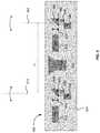
- FIG. 7illustrates schematically a three-dimensional imaging system 700 using scanning mirrors according to another embodiment of the present invention.
- the three-dimensional imaging system 700also includes a camera 602 , a first laser source 610 and a second laser source 630 configured to emit a first laser beam and a second laser beam, respectively, a first optical element 612 and a second optical element 632 configured to expand the first laser beam and the second laser beam into a first vertical fan of light 614 and a second vertical fan of light 634 , respectively, and a first mirror 620 and a second mirror 640 configured to reflect the first vertical fan of light 614 and the second vertical fan of light 634 , respectively, toward a scene in front of the camera 602 .
- the three-dimensional imaging system 700further includes a linking assembly 650 that mechanically links the first mirror 620 and the second mirror 640 .
- the linking assembly 650includes a first rod attached to the first mirror 620 , a second rod attached to the second mirror 640 , and a cross bar attached to the first rod and the second rod.
- the three-dimensional imaging system 700may include a single motor 624 configured to drive both the first mirror 620 and the second mirror 640 through the linking assembly.
- the linking assembly 650ensures that the first mirror 620 and the second mirror 640 are properly aligned with respect to each other and are scanned synchronously.
- the three-dimensional imaging system 700may include a single encoder 626 for measuring the rotation angle of the first mirror 620 or the rotation angle of the second mirror 640 .
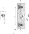
- FIG. 8illustrates a three-dimensional imaging system 800 according to another embodiment of the present invention.
- the three-dimensional imaging system 800is similar to the three-dimensional imaging system 600 , except that the two illumination sources are placed in two separate housings 604 and 606 . That is, the first laser source 610 , the first optical element 612 , the first mirror 620 , the first motor 624 , and the first encoder 626 are placed in the first housing 604 ; and the second laser source 630 , the second optical element 632 , the second mirror 640 , the second motor 644 , and the second encoder 646 are placed in the second housing 606 .
- the camera 602may be placed in either the first housing 604 or the second housing 606 .
- the camera 602may be placed in another separate housing.
- the two illumination sourcesin separate housings, it may be easier to vary the distance between the two fans of light 614 and 634 for possible trade-offs between resolution and detection range without redesigning the entire system. It may also be easier to mount the three-dimensional imaging system 800 in space-constrained areas, such as in the bumper of an autonomous vehicle.
- the requirement that the two fans of light be precisely parallel to each othermay be relaxed by calibrating 3D images of an object against a 3D target image of the object.
- a 3D target image of the objectcan be acquired by using a time-of-flight (TOF) lidar system.
- a 3D image of the object acquired by the three-dimensional imaging system 600 , 700 , or 800 as illustrated in FIGS. 6-8may then be compared against the 3D target image to generate a set of calibration coefficients.
- the set of calibration coefficientsmay include, for example, translation, rotation, and scaling coefficients, that can be applied to the 3D image acquired by the three-dimensional imaging system in order to match with the 3D target image.
- the calibrationcan be done in real time.
- the calibrationmay be performed beforehand, and the calibration coefficients may be stored and used by a control software.
- a control softwareBy relaxing the parallelism requirement, more flexibility in the design of the mounting system may be achieved.
- each illumination sourcemay be mounted individually, and the camera may be mounted separately from the illumination sources.
- the two illumination sourcesmay be mounted in the headlight fixtures of the vehicle.
- FIG. 9illustrates a three-dimensional imaging system 900 according to another embodiment of the present invention.
- the three-dimensional imaging system 900includes only one illumination source that may comprise a laser source 610 , an optical element 612 , a mirror 620 , a motor 624 , and an encoder 626 .
- the three-dimensional imaging system 900further includes a camera 602 .
- the illumination sourceprojects a fan of light 614 toward an object in the camera's field of view.
- the fan of light 614may form an illumination line on the object as it strikes the object.
- object distancemay be determined by the distortion in the position of the illumination line as seen in an image captured by the camera 602 based on a prior calibration using a known object.
- the amount of distortionmay depend on the baseline distance D between the axis of the camera 602 and the illumination axis.
- the illumination sourceis configured to scan the fan of light 614 across the field of view at a rate ranging from about 1 sweep per second to about 20 sweeps per second, such that the three-dimensional imaging system 900 operates at an image rate ranging from about 1 image per second to about 20 images per second.
- the lateral resolutionmay depend on both the scan rate of the illumination source and the frame rate of the camera 602 .
- FIG. 10illustrates a three-dimensional imaging system 1000 according to yet another embodiment of the present invention.
- the three-dimensional imaging system 1000is similar to the three-dimensional imaging system 900 illustrated in FIG. 9 , except that it includes a second camera 608 disposed on the opposite side of the illumination source from the first camera 602 .
- the view of the illumination line by one cameramay be blocked.
- Adding a second camera on the opposite side of the illumination sourcemay help ensure that at least one camera has a clear line-of-sight visibility of the illuminated line.
- a first baseline distance D 1 between the axis of the first camera and the illumination axismay be chosen to be different from a second baseline distance D 2 between the axis of the second camera and the illumination axis, such that one camera is optimized for optimal depth resolution for closer objects, and the other camera is optimized for long-range detection.
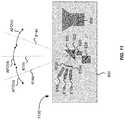
- FIG. 11illustrates a three-dimensional imaging system 1100 according to another embodiment of the present invention.
- the three-dimensional imaging system 1100is similar to the three-dimensional imaging system 900 illustrated in FIG. 9 , except that it includes three laser sources 610 a - 610 c and three optical elements 612 a - 612 c for expanding the laser beams emitted by the laser sources 610 a - 610 c into three vertical fans of light 614 a - 614 c , respectively.
- the scan range of the mirror 620may give rise to a certain angular field of view AFOVa, AFOVb, or AFOVc for each fan of light.
- the total angular field view TAFOVmay be the sum of the angular field view of the three individual fans of light AFOVa, AFOVb, and AFOVc.
- the angular field of view AFOVa, AFOVb, or AFOVc for each individual fan of lightmay be about 30 degrees, and the total angular field of view TAFOV may be about 90 degrees.
- a relatively small scan range of the mirror 620may give rise to a relatively large total field of view (e.g., 90 degrees or greater).
- the angular field of view of the adjacent fans of lightmay abut each other, or may partially overlap with each other.
- the three-dimensional imaging system 1100 illustrated in FIG. 11may afford several advantages.
- the relatively small scan range of the mirror 620may simplify the mechanical design and afford better reliability.
- itmay also increase the overall frame rate of the system for a given mechanical scan speed.
- fewer or more laser sourcesfor example 2 or 4 laser sources may be used.
- multiple fans of lightinstead of using multiple laser sources, multiple fans of light may be generated using a beam splitter, a diffractive optical element, a mirror with multiple facets, or the like. This approach may also be implemented in other embodiments of the present invention.
- the three-dimensional imaging system 600 , 700 , 800 illustrated in FIGS. 6-8instead of a single pair of fans of light, multiple pairs of fans of light may be generated, each pair covering a respective portion of the total angular field of view. It may also be implemented in the three-dimensional imaging system 1000 illustrated in FIG. 10 .
- the laser source(s) used in the three-dimensional imaging systems 600 , 700 , 800 , 900 , 1000 , and 1100 as illustrated in FIGS. 6-11may be configured to emit laser beams in the infrared (IR) wavelength range (e.g., 0.75 ⁇ m-1000 ⁇ m).
- IRinfrared
- the first laser source 610 and the second laser source 630may be configured to emit laser beams in the near infrared (NIR) wavelength range (e.g., 0.75 ⁇ m-1.4 ⁇ m), or in the short-wavelength infrared (e.g., 1.4 ⁇ m-3 ⁇ m), or in the mid-wavelength infrared wavelength range (e.g., 3 ⁇ m-8 ⁇ m).
- NIRnear infrared
- the energy levelscould be higher as the eye does not focus at those wavelengths.
- a narrow-band filtercan be used in front of the camera in conjunction with narrow band light sources, such as laser sources.
- narrow band light sourcessuch as laser sources.
- a multi-layer thin-film filtermay be designed to have a narrow transmission band in the infrared wavelength range of the laser sources, and have high reflectance for all other wavelengths.
- the center wavelength of the transmission bandis usually sensitive to the incidence angle.
- the center wavelength of the filtermay shift as light incident on the filter at different angles.
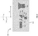
- FIG. 12illustrates a three-dimensional imaging system 1200 that includes a scanning filter 1260 according to an embodiment of the present invention.
- the three-dimensional imaging system 1200is similar to the three-dimensional imaging system 700 illustrated in FIG. 7 , which includes a camera 602 , two laser sources 610 and 630 , two mirrors 620 and 640 , and a scanning assembly 650 connecting the two mirrors 620 and 640 for scanning the two mirrors 620 and 640 synchronously.
- the three-dimensional imaging system 1200further includes a narrow-band filter 1260 disposed in front of the camera 602 .
- the narrow-band filter 1260may be configured to be scanned synchronously with the scanning of the two mirrors 620 and 640 , such that the laser light always incident on the filter 1260 at a constant angle. Note that this is only possible for a scanning illumination, as is the case for the three-dimensional imaging systems 600 , 700 , 800 , 900 , 1000 , and 1100 as illustrated in FIGS. 6-11 . If global illumination is used where the entire field of view is illuminated simultaneously, scanning of the filter 1260 will not eliminate the variation of incidence angles.
- Synchronization of the scanning of the filter 1260 with the scanning of the mirrors 620 and 640may be accomplished mechanically or electronically.
- the ratio of the scanning speed for the filter 1260 and the scanning speed of mirrorshould be about 2:1, as a one-degree change in the mirror angle results in a two-degree change in the angle of incidence.
- the filter 1260may be coupled to the scanning assembly 650 via a mechanical bar 1270 , so that the motor 604 drives the scanning of the mirrors 620 and 640 as well as the scanning of the filter 1260 .
- a lock-in detection techniquemay be used for ambient light rejection.
- the laser beams emitted by the laser sources 610 and 630may be modulated at a specific frequency, and the camera 602 may be configured to detect light at the same frequency in order to reject other signals.
- the camera 602may be operated with a trigger signal synchronized to the modulation frequency of the illumination signals.
- the camera 602may be configured to take one image with illumination on and another image with illumination off.
- the difference imagemay eliminate the background signals.
- FIG. 13illustrates schematically a three-dimensional imaging system 1300 using structured illumination according to an embodiment of the present invention.
- the three-dimensional imaging system 1300includes a camera 1302 , a first laser source 1310 , and a second laser source 1320 .
- the three-dimensional imaging system 1300further includes a first diffractive optical element 1330 and a second diffractive optical element 1340 .
- the first diffractive optical element 1330is disposed in front of the first laser source 1310 and configured to convert a laser beam emitted by the first laser source 1310 into a first structured (patterned) illumination 1350 projected at the field of view in front of the camera 1302 .
- the second diffractive optical element 1340is disposed in front of the second laser source 1320 and configured to convert a laser beam emitted by the second laser source 1320 into a second structured illumination 1360 .
- each of the first structured illumination 1350 and the second structured illumination 1360can be a grid pattern, vertical lines, horizontal lines, and the like.
- the first structured illumination 1350 and the second structured illumination 1360may have different uniquely identifiable patterns. As such, the system can be cross-calibrated against the two different illumination patterns.
- the two laser sources 1310 and 1320may be separated by a fixed baseline distance.
- the camera 1302may be optimally placed in between the two laser sources 1310 and 1320 , so that the camera 1302 is separated from the first laser source 1310 by a first fixed baseline distance D 1 , and from the second laser source 1320 by a second fixed baseline distance D 2 .
- the apparent distance between illumination points from the two laser sources 1310 and 1320 as seen in an image captured by the camera 1302may be used to determine the distance of an object in the field of view.
- the distortion of the patternmay be used to determine distance information.
- different baseline distancesmay be chosen for D 1 and D 2 . For example, one baseline distance may be optimized for good distance resolution for closer objects, and the other baseline distance may be optimized for long-range detection.
- the first structured illumination 1350 and the second structured illumination 1360may be made distinguishable in a number of ways. For instance, one may be horizontal lines, and the other vertical lines. Alternatively, they may be both grid patterns, but the patterns are offset so that one grid falls into the gaps of the other grid.
- the two laser sources 1310 and 1320can be modulated, alternately flashing in synchronicity with the camera frame rate to provide a high degree of separation and allow lock-in detection for background rejection.
- the two laser sources 1310 and 1320may be configured to operate in different wavelength ranges.
- the camera 1302may use narrow-band filters to discriminate between the two illumination wavelength ranges.
- two camerasmay be used, each with a different narrow-band filter.
- the filter for one cameramay be tuned to the wavelength range of the first laser source 1310
- the filter for the other cameramay be tuned to the wavelength range of the second laser source 1320 .
- the illuminations 1350 and 1360may be fixed, or scanned to allow a larger field of view or finer resolution.
- the two camerascan be used to further improve calibration by checking the performance of one against the other. Using two cameras can also help prevent loss of data if part of an object is obscured from the view of one of the cameras.
- FIG. 14illustrates a three-dimensional imaging system 1400 using structured illumination according another embodiment of the present invention.
- the three-dimensional imaging system 1400includes a first camera 1402 and a second camera 1404 , a single laser source 1410 , and a diffractive optical element 1430 disposed in front of the laser source 1410 and configured to convert a laser beam emitted by the laser source 1410 into a structured illumination 1450 in the field of view of the two cameras 1402 and 1404 .
- the first camera 1402 and the second camera 1404are separated from each other at a fixed baseline distance.
- the laser source 1410is preferably disposed between the first camera 1402 and the second camera 1404 , so that it is separated from the first camera 1402 by a first baseline distance D 1 , and from the second camera 1404 by a second baseline distance D 2 .
- Using two cameras instead of onemay allow more robust performance in several ways.
- an image of one cameramay be used to calibrate an image of the other camera, thus providing better distance accuracy and position accuracy.
- a different baseline distancemay be chosen for D 1 than D 2 . For example, one baseline distance may be optimized for good distance resolution for closer objects, and the other baseline distance may be optimized for long-range detection.
- FIG. 15illustrates schematically one or more three-dimensional imaging systems 1510 a - 1510 d mounted on an autonomous or semi-autonomous vehicle 1502 for obstacle detection according to an embodiment of the present invention.
- a first three-dimensional imaging system 1510 amay be mounted in the front side (e.g., a front bumper) of the vehicle 1502 for detecting objects in front of the vehicle 1502 ; a second three-dimensional imaging system 1510 b and a third three-dimensional imaging system 1510 c may be mounted on either side of the vehicle 1502 for detecting objects on the sides; and a fourth three-dimensional imaging system 1510 d may be mounted on the rear (e.g., on a rear bumper) of the vehicle 1502 for detecting objects behind the vehicle 1502 .
- the first three-dimensional imaging system 1510 a mounted on the front side the of vehicle 1502may be configured for long range detection
- the second three-dimensional imaging system 1510 b , the third three-dimensional imaging system 1510 c , and the fourth three-dimensional imaging system 1510 dmay be configured for medium or short range detection.
Landscapes
- Engineering & Computer Science (AREA)
- Physics & Mathematics (AREA)
- General Physics & Mathematics (AREA)
- Remote Sensing (AREA)
- Computer Networks & Wireless Communication (AREA)
- Radar, Positioning & Navigation (AREA)
- Electromagnetism (AREA)
- Multimedia (AREA)
- Theoretical Computer Science (AREA)
- Signal Processing (AREA)
- Computer Vision & Pattern Recognition (AREA)
- Optics & Photonics (AREA)
- Mechanical Engineering (AREA)
- Optical Radar Systems And Details Thereof (AREA)
- Length Measuring Devices By Optical Means (AREA)
Abstract
Description
Claims (11)
Priority Applications (6)
| Application Number | Priority Date | Filing Date | Title |
|---|---|---|---|
| US15/389,368US10754036B2 (en) | 2016-04-26 | 2016-12-22 | Scanning illuminated three-dimensional imaging systems |
| PCT/US2017/025785WO2017189185A1 (en) | 2016-04-26 | 2017-04-03 | Three-dimensional imaging systems |
| CN201780039604.9ACN109416399B (en) | 2016-04-26 | 2017-04-03 | 3D Imaging System |
| JP2018557022AJP7108308B2 (en) | 2016-04-26 | 2017-04-03 | 3D imaging system |
| EP17790087.5AEP3449274A4 (en) | 2016-04-26 | 2017-04-03 | THREE-DIMENSIONAL IMAGING SYSTEMS |
| JP2022110808AJP7332210B2 (en) | 2016-04-26 | 2022-07-08 | 3D imaging system |
Applications Claiming Priority (2)
| Application Number | Priority Date | Filing Date | Title |
|---|---|---|---|
| US201662327447P | 2016-04-26 | 2016-04-26 | |
| US15/389,368US10754036B2 (en) | 2016-04-26 | 2016-12-22 | Scanning illuminated three-dimensional imaging systems |
Publications (2)
| Publication Number | Publication Date |
|---|---|
| US20170310948A1 US20170310948A1 (en) | 2017-10-26 |
| US10754036B2true US10754036B2 (en) | 2020-08-25 |
Family
ID=60088474
Family Applications (4)
| Application Number | Title | Priority Date | Filing Date |
|---|---|---|---|
| US15/267,558Active2038-01-10US10451740B2 (en) | 2016-04-26 | 2016-09-16 | Scanning lidar systems for three-dimensional sensing |
| US15/288,206Active2038-01-30US10481266B2 (en) | 2016-04-26 | 2016-10-07 | Multi-range three-dimensional imaging systems |
| US15/389,368Active2037-12-05US10754036B2 (en) | 2016-04-26 | 2016-12-22 | Scanning illuminated three-dimensional imaging systems |
| US16/574,616Active2037-01-27US11300684B2 (en) | 2016-04-26 | 2019-09-18 | Scanning lidar systems for three-dimensional sensing |
Family Applications Before (2)
| Application Number | Title | Priority Date | Filing Date |
|---|---|---|---|
| US15/267,558Active2038-01-10US10451740B2 (en) | 2016-04-26 | 2016-09-16 | Scanning lidar systems for three-dimensional sensing |
| US15/288,206Active2038-01-30US10481266B2 (en) | 2016-04-26 | 2016-10-07 | Multi-range three-dimensional imaging systems |
Family Applications After (1)
| Application Number | Title | Priority Date | Filing Date |
|---|---|---|---|
| US16/574,616Active2037-01-27US11300684B2 (en) | 2016-04-26 | 2019-09-18 | Scanning lidar systems for three-dimensional sensing |
Country Status (5)
| Country | Link |
|---|---|
| US (4) | US10451740B2 (en) |
| EP (1) | EP3449274A4 (en) |
| JP (2) | JP7108308B2 (en) |
| CN (1) | CN109416399B (en) |
| WO (1) | WO2017189185A1 (en) |
Cited By (1)
| Publication number | Priority date | Publication date | Assignee | Title |
|---|---|---|---|---|
| US11644303B2 (en) | 2019-12-16 | 2023-05-09 | Faro Technologies, Inc. | Three-dimensional coordinate measuring instrument coupled to a camera having a diffractive optical element |
Families Citing this family (146)
| Publication number | Priority date | Publication date | Assignee | Title |
|---|---|---|---|---|
| US11493634B2 (en) | 2015-02-13 | 2022-11-08 | Carnegie Mellon University | Programmable light curtains |
| US11972586B2 (en) | 2015-02-13 | 2024-04-30 | Carnegie Mellon University | Agile depth sensing using triangulation light curtains |
| US11425357B2 (en)* | 2015-02-13 | 2022-08-23 | Carnegie Mellon University | Method for epipolar time of flight imaging |
| US11747135B2 (en) | 2015-02-13 | 2023-09-05 | Carnegie Mellon University | Energy optimized imaging system with synchronized dynamic control of directable beam light source and reconfigurably masked photo-sensor |
| US12123950B2 (en) | 2016-02-15 | 2024-10-22 | Red Creamery, LLC | Hybrid LADAR with co-planar scanning and imaging field-of-view |
| US12399279B1 (en) | 2016-02-15 | 2025-08-26 | Red Creamery Llc | Enhanced hybrid LIDAR with high-speed scanning |
| US12399278B1 (en) | 2016-02-15 | 2025-08-26 | Red Creamery Llc | Hybrid LIDAR with optically enhanced scanned laser |
| US11556000B1 (en) | 2019-08-22 | 2023-01-17 | Red Creamery Llc | Distally-actuated scanning mirror |
| US9866816B2 (en) | 2016-03-03 | 2018-01-09 | 4D Intellectual Properties, Llc | Methods and apparatus for an active pulsed 4D camera for image acquisition and analysis |
| US10761195B2 (en) | 2016-04-22 | 2020-09-01 | OPSYS Tech Ltd. | Multi-wavelength LIDAR system |
| US10451740B2 (en) | 2016-04-26 | 2019-10-22 | Cepton Technologies, Inc. | Scanning lidar systems for three-dimensional sensing |
| USD832845S1 (en)* | 2016-08-01 | 2018-11-06 | Hand Held Products, Inc. | Optical scanner |
| DE102016220468A1 (en)* | 2016-10-19 | 2018-04-19 | Robert Bosch Gmbh | Lidar sensor for detecting an object |
| DE102016220504A1 (en)* | 2016-10-19 | 2018-04-19 | Robert Bosch Gmbh | 3D LIDAR sensor |
| US10684358B2 (en)* | 2016-11-11 | 2020-06-16 | Raytheon Company | Situational awareness sensor using a fixed configuration of optical phased arrays (OPAs) |
| IT201700021559A1 (en)* | 2017-02-27 | 2018-08-27 | St Microelectronics Srl | CORRESPONDENT PROCEDURE FOR THE CONTROL OF LASER RAYS, DEVICE, EQUIPMENT AND COMPUTER PRODUCT |
| KR102619582B1 (en) | 2017-03-13 | 2024-01-02 | 옵시스 테크 엘티디 | Eye-Safe Scanning LIDAR System |
| US10114111B2 (en)* | 2017-03-28 | 2018-10-30 | Luminar Technologies, Inc. | Method for dynamically controlling laser power |
| US20180284246A1 (en)* | 2017-03-31 | 2018-10-04 | Luminar Technologies, Inc. | Using Acoustic Signals to Modify Operation of a Lidar System |
| US10677897B2 (en) | 2017-04-14 | 2020-06-09 | Luminar Technologies, Inc. | Combining lidar and camera data |
| KR102218679B1 (en) | 2017-07-28 | 2021-02-23 | 옵시스 테크 엘티디 | VCSEL Array LIDAR Transmitter with Small Angle Divergence |
| US10346994B2 (en)* | 2017-07-29 | 2019-07-09 | Verizon Patent And Licensing Inc. | Systems and methods for inward-looking depth scanning of a real-world scene |
| US10317905B2 (en)* | 2017-08-10 | 2019-06-11 | RavenOPS, Inc. | Autonomous robotic technologies for industrial inspection |
| US11460550B2 (en) | 2017-09-19 | 2022-10-04 | Veoneer Us, Llc | Direct detection LiDAR system and method with synthetic doppler processing |
| EP3460518B1 (en)* | 2017-09-22 | 2024-03-13 | Leica Geosystems AG | Hybrid lidar-imaging device for aerial surveying |
| JP7117092B2 (en)* | 2017-09-25 | 2022-08-12 | 株式会社トプコン | LASER MEASUREMENT METHOD AND LASER MEASUREMENT DEVICE |
| US11194022B2 (en) | 2017-09-29 | 2021-12-07 | Veoneer Us, Inc. | Detection system with reflection member and offset detection array |
| US10921431B2 (en) | 2017-10-19 | 2021-02-16 | Cepton Technologies Inc. | Apparatuses for scanning a lidar system in two dimensions |
| USD848428S1 (en)* | 2017-11-08 | 2019-05-14 | Lee Seng Fook | Hand held 3D scanning device |
| USD848429S1 (en)* | 2017-11-08 | 2019-05-14 | Lee Seng Fook | Hand held 3D scanning device with feedback system |
| US11585901B2 (en) | 2017-11-15 | 2023-02-21 | Veoneer Us, Llc | Scanning lidar system and method with spatial filtering for reduction of ambient light |
| EP3710855A4 (en) | 2017-11-15 | 2021-08-04 | Opsys Tech Ltd. | Noise adaptive solid-state lidar system |
| US10816666B2 (en)* | 2017-11-21 | 2020-10-27 | Magna Electronics Inc. | Vehicle sensing system with calibration/fusion of point cloud partitions |
| US11585902B2 (en) | 2017-11-30 | 2023-02-21 | Cepton Technologies, Inc. | Optical designs using cylindrical lenses for improved resolution in lidar systems |
| DE102017221797A1 (en)* | 2017-12-04 | 2019-06-06 | Osram Gmbh | Lidar system for environment detection and method for operating a lidar system |
| CN109884656B (en)* | 2017-12-06 | 2021-05-28 | 北京万集科技股份有限公司 | Lidar and ranging method for realizing scanning field of view division |
| CN109313822B (en)* | 2017-12-13 | 2020-04-10 | 广州艾若博机器人科技有限公司 | Virtual wall construction method and device based on machine vision, map construction method and movable electronic equipment |
| US11662433B2 (en) | 2017-12-22 | 2023-05-30 | Denso Corporation | Distance measuring apparatus, recognizing apparatus, and distance measuring method |
| CN108254736B (en)* | 2017-12-31 | 2022-05-13 | 天津木牛流马科技发展股份有限公司 | Submillimeter-level laser radar |
| CN108241146A (en)* | 2018-01-15 | 2018-07-03 | 深圳市速腾聚创科技有限公司 | Laser radar and the method for improving laser radar launch point frequency |
| EP4321898A3 (en)* | 2018-01-17 | 2024-04-24 | Hesai Technology Co., Ltd. | Detection device and method for adjusting parameter thereof |
| DE102018201508B4 (en)* | 2018-02-01 | 2021-03-18 | Robert Bosch Gmbh | Use in a LiDAR system of a method for operating a LiDAR system by emitting laser light in the form of laser pulses |
| US10771690B2 (en)* | 2018-02-10 | 2020-09-08 | Goodrich Corporation | Distributed aperture systems for obstacle avoidance |
| US11592527B2 (en) | 2018-02-16 | 2023-02-28 | Cepton Technologies, Inc. | Systems for incorporating LiDAR sensors in a headlamp module of a vehicle |
| US20190285734A1 (en)* | 2018-03-14 | 2019-09-19 | Infineon Technologies Ag | Detection system with configurable range and field of view |
| KR102604050B1 (en) | 2018-04-01 | 2023-11-22 | 옵시스 테크 엘티디 | Noise adaptive solid-state lidar system |
| CN112204486B (en)* | 2018-04-03 | 2024-08-09 | 尚科宁家运营有限公司 | Time-of-flight sensor arrangement for robot navigation and method for positioning using the same |
| US10694168B2 (en)* | 2018-04-22 | 2020-06-23 | Corephotonics Ltd. | System and method for mitigating or preventing eye damage from structured light IR/NIR projector systems |
| KR102466555B1 (en) | 2018-06-14 | 2022-11-14 | 현대모비스 주식회사 | Lidar sensor and control method thereof |
| DE102018131201A1 (en)* | 2018-06-21 | 2019-12-24 | pmdtechnologies ag | Time-of-flight camera system with an adjustable optical output power |
| CN109116331B (en)* | 2018-06-27 | 2020-04-24 | 上海禾赛光电科技有限公司 | Coding laser transceiver, distance measuring device and laser radar system |
| US10466342B1 (en) | 2018-09-30 | 2019-11-05 | Hesai Photonics Technology Co., Ltd. | Adaptive coding for lidar systems |
| JP7077822B2 (en) | 2018-07-05 | 2022-05-31 | 株式会社デンソー | Optical range measuring device |
| US11822020B2 (en) | 2018-07-10 | 2023-11-21 | Cepton Technologies, Inc. | Scanning lidar systems with moving lens assembly |
| US20200019192A1 (en) | 2018-07-13 | 2020-01-16 | Caterpillar Paving Products Inc. | Object detection and implement position detection system |
| US10627516B2 (en) | 2018-07-19 | 2020-04-21 | Luminar Technologies, Inc. | Adjustable pulse characteristics for ground detection in lidar systems |
| DE102018118584A1 (en) | 2018-07-31 | 2020-02-06 | Blickfeld GmbH | Vehicle headlights with LIDAR module |
| CN110850859B (en)* | 2018-08-01 | 2023-03-07 | 深圳市优必选科技有限公司 | Robot and obstacle avoidance method and obstacle avoidance system thereof |
| JP2021532368A (en) | 2018-08-03 | 2021-11-25 | オプシス テック リミテッド | Distributed modular solid-state lidar system |
| GB2579689A (en)* | 2018-08-07 | 2020-07-01 | Cambridge Mechatronics Ltd | Improved 3D sensing |
| EP3627175B1 (en) | 2018-09-19 | 2020-07-22 | Sick Ag | Optoelectronic sensor and method for deflecting a beam of light |
| JP7242234B2 (en)* | 2018-09-28 | 2023-03-20 | キヤノン株式会社 | Photodetector, photodetection system |
| DE102018216707A1 (en)* | 2018-09-28 | 2020-04-02 | Ibeo Automotive Systems GmbH | Environment detection system and method for an environment detection system |
| US20200103504A1 (en)* | 2018-10-02 | 2020-04-02 | GM Global Technology Operations LLC | Multiple photonic chip lidar system architecture |
| US11269065B2 (en)* | 2018-11-19 | 2022-03-08 | Infineon Technologies Ag | Muilti-detector with interleaved photodetector arrays and analog readout circuits for lidar receiver |
| DE102018220227A1 (en)* | 2018-11-26 | 2020-05-28 | Robert Bosch Gmbh | LIDAR sensor and method for optically detecting a field of view |
| KR102806085B1 (en)* | 2018-12-03 | 2025-05-12 | 삼성전자주식회사 | LiDAR device and method of driving the same |
| US11423572B2 (en) | 2018-12-12 | 2022-08-23 | Analog Devices, Inc. | Built-in calibration of time-of-flight depth imaging systems |
| CN111381246B (en)* | 2018-12-27 | 2025-07-11 | 武汉万集光电技术有限公司 | Laser radar receiving component and laser radar system |
| US11374041B2 (en)* | 2019-01-25 | 2022-06-28 | Cepton Technologies, Inc. | Systems and methods for imaging using mechanical scanning mechanisms |
| CA3173966A1 (en)* | 2019-03-08 | 2020-09-17 | Leddartech Inc. | Lidar system, appartus communicating with the lidar system, and apparatus located in a field of view (fov) of the lidar system |
| JP2020153798A (en)* | 2019-03-19 | 2020-09-24 | 株式会社リコー | Optical device, range finder optical system unit, range finder and range finder system |
| JP2020153796A (en) | 2019-03-19 | 2020-09-24 | 株式会社リコー | Distance measuring device and distance measuring method |
| US11467270B2 (en)* | 2019-03-27 | 2022-10-11 | Asmpt Singapore Pte. Ltd. | Apparatus and method for calibrating or testing an imaging device |
| CN113692540B (en) | 2019-04-09 | 2025-06-17 | 欧普赛斯技术有限公司 | Solid-state LIDAR transmitter with laser control |
| CN109991588A (en)* | 2019-04-29 | 2019-07-09 | 北京握奇数据股份有限公司 | A kind of laser radar scanning device |
| CN110244318B (en)* | 2019-04-30 | 2021-08-17 | 深圳市光鉴科技有限公司 | 3D imaging method based on asynchronous ToF discrete point cloud |
| US11568636B2 (en)* | 2019-05-02 | 2023-01-31 | Advanced Geosciences, Inc. | Reflective cable locating system |
| US11480685B2 (en)* | 2019-05-05 | 2022-10-25 | Apple Inc. | Compact optical packaging of LiDAR systems using diffractive structures behind angled interfaces |
| JP2020187079A (en)* | 2019-05-17 | 2020-11-19 | 三菱重工業株式会社 | Laser radar system and traveling body |
| CN110764099A (en)* | 2019-05-24 | 2020-02-07 | Oppo广东移动通信有限公司 | Time-of-flight sensor and computer-readable storage medium |
| US11796643B2 (en) | 2019-05-30 | 2023-10-24 | Microvision, Inc. | Adaptive LIDAR scanning methods |
| JP7603998B2 (en) | 2019-05-30 | 2024-12-23 | オプシス テック リミテッド | Eye-safe long-range LIDAR system using actuators |
| US11828881B2 (en) | 2019-05-30 | 2023-11-28 | Microvision, Inc. | Steered LIDAR system with arrayed receiver |
| US11754682B2 (en)* | 2019-05-30 | 2023-09-12 | Microvision, Inc. | LIDAR system with spatial beam combining |
| US11513195B2 (en) | 2019-06-10 | 2022-11-29 | OPSYS Tech Ltd. | Eye-safe long-range solid-state LIDAR system |
| EP3990943A4 (en) | 2019-06-25 | 2023-07-05 | Opsys Tech Ltd. | Adaptive multiple-pulse lidar system |
| US10955241B2 (en)* | 2019-06-26 | 2021-03-23 | Aurora Flight Sciences Corporation | Aircraft imaging system using projected patterns on featureless surfaces |
| KR20210003003A (en)* | 2019-07-01 | 2021-01-11 | 삼성전자주식회사 | Lidar apparatus and controlling method thereof |
| US11474218B2 (en) | 2019-07-15 | 2022-10-18 | Veoneer Us, Llc | Scanning LiDAR system and method with unitary optical element |
| US11579257B2 (en) | 2019-07-15 | 2023-02-14 | Veoneer Us, Llc | Scanning LiDAR system and method with unitary optical element |
| KR20220038691A (en) | 2019-07-31 | 2022-03-29 | 옵시스 테크 엘티디 | High-Resolution Solid-State LIDAR Transmitter |
| JP2021028594A (en)* | 2019-08-09 | 2021-02-25 | パイオニア株式会社 | Light projecting/receiving device, range finder and rotary body device |
| CN110673114B (en)* | 2019-08-27 | 2023-04-18 | 三赢科技(深圳)有限公司 | Method and device for calibrating depth of three-dimensional camera, computer device and storage medium |
| US11808858B2 (en) | 2019-09-04 | 2023-11-07 | Pony Ai Inc. | Systems and methods for constructing and utilizing field-of-view (FOV) information |
| US11639846B2 (en) | 2019-09-27 | 2023-05-02 | Honeywell International Inc. | Dual-pattern optical 3D dimensioning |
| US11450083B2 (en) | 2019-09-27 | 2022-09-20 | Honeywell International Inc. | Dual-pattern optical 3D dimensioning |
| US11150348B2 (en) | 2019-10-02 | 2021-10-19 | Cepton Technologies, Inc. | Techniques for detecting cross-talk interferences in lidar imaging sensors |
| US11598217B2 (en)* | 2019-10-17 | 2023-03-07 | Dassault Systemes Simulia Corp. | Method for automatic calculation of axial cooling fan shroud circular opening size |
| DE102019217165A1 (en)* | 2019-11-07 | 2021-05-12 | Robert Bosch Gmbh | Operating method and control unit for a LiDAR system, LiDAR system and device |
| US20230028749A1 (en)* | 2019-12-20 | 2023-01-26 | Ams Sensors Asia Pte. Ltd | Lidar with multi-range channels |
| WO2021126082A1 (en)* | 2019-12-20 | 2021-06-24 | Ams Sensors Asia Pte. Ltd. | Eye-safe operation of lidar scanner |
| RU2762744C2 (en) | 2019-12-23 | 2021-12-22 | Общество с ограниченной ответственностью "Яндекс Беспилотные Технологии" | METHODS AND SYSTEMS FOR DETECTING USING LIDAR (LiDAR) WITH FIBER-OPTICAL MATRIX |
| US12085647B2 (en)* | 2019-12-27 | 2024-09-10 | Waymo Llc | LIDAR occlusion detection methods and systems |
| US12313784B2 (en) | 2019-12-30 | 2025-05-27 | Cepton Technologies, Inc. | Half and quarter lissajous scan patterns for LiDAR |
| CN116017164B (en)* | 2019-12-30 | 2024-12-27 | 马特波特公司 | System and method for capturing and generating panoramic three-dimensional images |
| CN111103297B (en)* | 2020-01-20 | 2024-07-12 | 无锡市建筑工程质量检测中心 | Non-contact detection method and detection system for quality of building exterior wall surface layer |
| KR102550678B1 (en)* | 2020-01-22 | 2023-07-04 | 노다르 인크. | Non-Rigid Stereo Vision Camera System |
| US11427193B2 (en) | 2020-01-22 | 2022-08-30 | Nodar Inc. | Methods and systems for providing depth maps with confidence estimates |
| JP7283413B2 (en)* | 2020-02-17 | 2023-05-30 | 株式会社デンソー | IN-VEHICLE MEASURING DEVICE UNIT AND INTEGRATED DATA GENERATION METHOD IN IN-VEHICLE MEASURING DEVICE UNIT |
| JP2021148746A (en)* | 2020-03-23 | 2021-09-27 | 株式会社リコー | Distance measuring device and distance measuring method |
| DE102020110142A1 (en)* | 2020-04-14 | 2021-10-14 | Scantinel Photonics GmbH | Device and method for the scanning measurement of the distance to an object |
| WO2022006158A1 (en)* | 2020-06-29 | 2022-01-06 | Brain Corporation | Systems, apparatuses, and methods for calibrating lidar sensors of a robot using intersecting lidar sensors |
| US20230237766A1 (en)* | 2020-07-08 | 2023-07-27 | Michigan Scientific Corporation | Speed And Slip Determinations For A Vehicle Using Optical Flow Technology |
| CN111766949B (en)* | 2020-07-16 | 2021-08-03 | 腾讯科技(深圳)有限公司 | Three-dimensional image display device, display method, electronic device, and storage medium |
| US11698447B2 (en)* | 2020-07-17 | 2023-07-11 | Infineon Technologies Ag | Beam steering aware pixel clustering of segmented sensor area and implementing averaging algorithms for pixel processing |
| KR20230054612A (en)* | 2020-08-28 | 2023-04-25 | 헤사이 테크놀로지 씨오., 엘티디. | Laser radar and distance measurement methods |
| CN114594486B (en)* | 2020-12-04 | 2025-05-30 | 上海禾赛科技有限公司 | Method, processor and laser radar system for filtering out drag points in radar point cloud |
| US12079673B2 (en) | 2021-02-12 | 2024-09-03 | Scandit Ag | Optical pattern decoding in a real scene using overlay functionality |
| US12175327B1 (en) | 2020-12-04 | 2024-12-24 | Scandit Ag | Camera start optimization for optical pattern decoding |
| CN112684456B (en)* | 2020-12-22 | 2024-05-17 | 安徽配隆天环保科技有限公司 | Unmanned aerial vehicle ultrasonic three-dimensional imaging model system |
| US12044800B2 (en) | 2021-01-14 | 2024-07-23 | Magna Electronics, Llc | Scanning LiDAR system and method with compensation for transmit laser pulse effects |
| KR20230150978A (en)* | 2021-02-23 | 2023-10-31 | 뉴럴 프로펄전 시스템즈, 인크. | Lidar systems and methods with improved eye safety |
| US11326758B1 (en) | 2021-03-12 | 2022-05-10 | Veoneer Us, Inc. | Spotlight illumination system using optical element |
| CN113109789B (en)* | 2021-04-09 | 2024-07-09 | 深圳煜炜光学科技有限公司 | Multi-line scanning laser radar device and control method |
| US11922799B2 (en)* | 2021-04-17 | 2024-03-05 | Charles R. Crittenden | Apparatus and method for a warning system |
| EP4321897A4 (en)* | 2021-04-29 | 2024-06-05 | Huawei Technologies Co., Ltd. | LASER DETECTION DEVICE AND CONTROL METHOD AND CONTROL DEVICE THEREFOR AND TERMINAL DEVICE |
| CN113189609A (en)* | 2021-05-31 | 2021-07-30 | 阿波罗智联(北京)科技有限公司 | Base, roadside sensing equipment and intelligent transportation system |
| US11732858B2 (en) | 2021-06-18 | 2023-08-22 | Veoneer Us, Llc | Headlight illumination system using optical element |
| US20230029105A1 (en)* | 2021-07-21 | 2023-01-26 | Seagate Technology Llc | Fingertip lidar system for visual assistance |
| CN113534191B (en)* | 2021-07-26 | 2022-11-29 | 重庆连芯光电技术研究院有限公司 | 3d image scanning and repairing method, device and equipment of single photon laser radar |
| DE102021208089A1 (en) | 2021-07-27 | 2023-02-02 | Robert Bosch Gesellschaft mit beschränkter Haftung | Method of operating a LiDAR device |
| US11577748B1 (en) | 2021-10-08 | 2023-02-14 | Nodar Inc. | Real-time perception system for small objects at long range for autonomous vehicles |
| CN115015295B (en)* | 2022-05-13 | 2025-08-12 | 中国科学院高能物理研究所 | X-ray detection device and detection method for micro-channel plate collimator |
| CN117518125A (en)* | 2022-07-29 | 2024-02-06 | 深圳市速腾聚创科技有限公司 | Lidar and lidar design methods |
| CN115339384A (en)* | 2022-08-18 | 2022-11-15 | 惠州市德赛西威智能交通技术研究院有限公司 | Vehicle driving assistance system, method, storage medium and vehicle |
| CN115390087A (en)* | 2022-08-24 | 2022-11-25 | 跨维(深圳)智能数字科技有限公司 | Laser line scanning three-dimensional imaging system and method |
| CN115407478B (en)* | 2022-08-25 | 2024-06-25 | 苏州立创致恒电子科技有限公司 | Three-dimensional imaging system and method for self-adaptive detection distance |
| US12092278B2 (en) | 2022-10-07 | 2024-09-17 | Magna Electronics, Llc | Generating a spotlight |
| US12228653B2 (en) | 2022-10-07 | 2025-02-18 | Magna Electronics, Llc | Integrating a sensing system into headlight optics |
| CN115862336B (en)* | 2023-02-27 | 2023-06-02 | 云南省交通规划设计研究院有限公司 | Vehicle running parameter detection device based on double laser sensors |
| CN116466327A (en)* | 2023-03-07 | 2023-07-21 | 深圳信通智能系统技术有限公司 | Laser radar system |
| DE102023205343A1 (en)* | 2023-06-07 | 2024-12-12 | Tripleye Gmbh | Device for spatial image capture of an environment moving relative to the device and operating method therefor |
| CN116973347B (en)* | 2023-07-19 | 2024-02-09 | 哈尔滨工业大学 | An excitation measurement device and application based on SLIPI-3DLIF |
| US12202396B1 (en) | 2023-12-19 | 2025-01-21 | Magna Electronics, Llc | Line-scan-gated imaging for LiDAR headlight |
| DE102024101015A1 (en)* | 2024-01-15 | 2025-07-17 | Cival Medical Gmbh | Medical lighting device |
Citations (13)
| Publication number | Priority date | Publication date | Assignee | Title |
|---|---|---|---|---|
| JP3169074B2 (en) | 1998-09-25 | 2001-05-21 | 日本電気株式会社 | Laser radar device |
| JP2002181533A (en) | 2000-12-18 | 2002-06-26 | Hitachi Ltd | Laser distance measuring device |
| US20030174305A1 (en)* | 2000-08-01 | 2003-09-18 | Michael Kasper | Measuring device and measuring method for determining distance and/or position |
| US6629641B2 (en)* | 2000-06-07 | 2003-10-07 | Metrologic Instruments, Inc. | Method of and system for producing images of objects using planar laser illumination beams and image detection arrays |
| US20040141170A1 (en) | 2003-01-21 | 2004-07-22 | Jamieson James R. | System for profiling objects on terrain forward and below an aircraft utilizing a cross-track laser altimeter |
| US20040233416A1 (en)* | 2001-08-06 | 2004-11-25 | Gunter Doemens | Method and device for recording a three-dimensional distance-measuring image |
| US20070219720A1 (en)* | 2006-03-16 | 2007-09-20 | The Gray Insurance Company | Navigation and control system for autonomous vehicles |
| US20080246943A1 (en) | 2005-02-01 | 2008-10-09 | Laser Projection Technologies, Inc. | Laser radar projection with object feature detection and ranging |
| US7544945B2 (en) | 2006-02-06 | 2009-06-09 | Avago Technologies General Ip (Singapore) Pte. Ltd. | Vertical cavity surface emitting laser (VCSEL) array laser scanner |
| US20140043309A1 (en)* | 2012-08-10 | 2014-02-13 | Nakhoon Go | Distance detecting device and image processing apparatus including the same |
| WO2014060562A1 (en) | 2012-10-17 | 2014-04-24 | Cathx Research Ltd | Improvements in relation to underwater imaging for underwater surveys |
| US20150075066A1 (en) | 2013-09-13 | 2015-03-19 | Palo Alto Research Center Incorporated | Unwanted plant removal system having variable optics |
| US20150296201A1 (en) | 2008-11-25 | 2015-10-15 | Tetravue, Inc. | Systems and method of high resolution three-dimensional imaging |
Family Cites Families (33)
| Publication number | Priority date | Publication date | Assignee | Title |
|---|---|---|---|---|
| JPH05288857A (en)* | 1992-04-13 | 1993-11-05 | Nec Corp | Laser radar device |
| JPH0675047A (en)* | 1992-08-25 | 1994-03-18 | Furukawa Electric Co Ltd:The | Optical radar for searching obstacle |
| US5852492A (en)* | 1996-06-07 | 1998-12-22 | Lockheed Martin Vought Systems Corp. | Fused lasar range/intensity image display for a human interpretation of lasar data |
| US6556282B2 (en)* | 2001-09-04 | 2003-04-29 | Rosemount Aerospace, Inc. | Combined LOAS and LIDAR system |
| JP3986928B2 (en) | 2002-08-23 | 2007-10-03 | 本田技研工業株式会社 | Object detection device |
| US7236235B2 (en) | 2004-07-06 | 2007-06-26 | Dimsdale Engineering, Llc | System and method for determining range in 3D imaging systems |
| DE102005034729B3 (en)* | 2005-07-21 | 2007-02-08 | Eads Deutschland Gmbh | Method and lidar system for measuring air turbulence on board aircraft, airports and wind farms |
| US8493445B2 (en)* | 2006-05-31 | 2013-07-23 | Sigma Space Corp | Scanner/optical system for three-dimensional lidar imaging and polarimetry |
| DE102007010236B4 (en)* | 2007-03-02 | 2008-11-20 | Toposys Topographische Systemdaten Gmbh | Device and method for distance determination by means of light pulses |
| US8027029B2 (en)* | 2007-11-07 | 2011-09-27 | Magna Electronics Inc. | Object detection and tracking system |
| US8119971B2 (en)* | 2008-01-17 | 2012-02-21 | Ball Corporation | Pulse data recorder in which a value held by a bit of a memory is determined by a state of a switch |
| US9041915B2 (en)* | 2008-05-09 | 2015-05-26 | Ball Aerospace & Technologies Corp. | Systems and methods of scene and action capture using imaging system incorporating 3D LIDAR |
| JP5570708B2 (en) | 2008-05-29 | 2014-08-13 | オムロンオートモーティブエレクトロニクス株式会社 | Object detection device |
| DE102008031681A1 (en)* | 2008-07-04 | 2010-01-14 | Eads Deutschland Gmbh | LIDAR method for measuring velocities and LIDAR device with timed detection |
| CN101419711B (en)* | 2008-12-15 | 2012-05-30 | 东软集团股份有限公司 | Method and device for estimating vehicle self-motion parameters |
| JP2010164463A (en) | 2009-01-16 | 2010-07-29 | Mitsubishi Electric Corp | Laser three-dimensional image measuring device |
| US8810796B2 (en)* | 2009-04-21 | 2014-08-19 | Michigan Aerospace Corporation | Light processing system and method |
| US8797550B2 (en)* | 2009-04-21 | 2014-08-05 | Michigan Aerospace Corporation | Atmospheric measurement system |
| EP2460034B1 (en)* | 2009-07-29 | 2015-09-09 | Michigan Aerospace Corporation | Atmospheric measurement system |
| US8600606B2 (en)* | 2010-02-11 | 2013-12-03 | GM Global Technology Operations LLC | Vehicle safety systems and methods |
| US8494687B2 (en)* | 2010-03-12 | 2013-07-23 | The United States Of America As Represented By The Administrator Of The National Aeronautics And Space Administration | Method for enhancing a three dimensional image from a plurality of frames of flash LIDAR data |
| US8655513B2 (en)* | 2010-03-12 | 2014-02-18 | The United States Of America As Represented By The Administrator Of The National Aeronautics And Space Administration | Methods of real time image enhancement of flash LIDAR data and navigating a vehicle using flash LIDAR data |
| US9086488B2 (en)* | 2010-04-20 | 2015-07-21 | Michigan Aerospace Corporation | Atmospheric measurement system and method |
| US8558993B2 (en)* | 2010-05-21 | 2013-10-15 | The National Institute of Standards and Technology, as Presented by the Secretary of Commerce | Optical frequency comb-based coherent LIDAR |
| US8736818B2 (en)* | 2010-08-16 | 2014-05-27 | Ball Aerospace & Technologies Corp. | Electronically steered flash LIDAR |
| US11313678B2 (en)* | 2011-06-30 | 2022-04-26 | The Regents Of The University Of Colorado | Remote measurement of shallow depths in semi-transparent media |
| US9304203B1 (en)* | 2013-03-13 | 2016-04-05 | Google Inc. | Methods, devices, and systems for improving dynamic range of signal receiver |
| US9778363B2 (en)* | 2013-10-24 | 2017-10-03 | Massachusetts Institute Of Technology | Methods and apparatus for coded time-of-flight camera |
| JP2015111090A (en)* | 2013-11-05 | 2015-06-18 | 株式会社リコー | Object detection device |
| JP6338242B2 (en)* | 2014-04-11 | 2018-06-06 | 国立大学法人 東京大学 | Distance image generator |
| CN104459183B (en)* | 2014-12-24 | 2017-07-07 | 四川大学 | A kind of one camera vehicle speed measuring system and method based on Internet of Things |
| US10495281B2 (en)* | 2015-11-09 | 2019-12-03 | Mitsubishi Electric Corporation | Projection optical instrument and headlight device |
| US10451740B2 (en) | 2016-04-26 | 2019-10-22 | Cepton Technologies, Inc. | Scanning lidar systems for three-dimensional sensing |
- 2016
- 2016-09-16USUS15/267,558patent/US10451740B2/enactiveActive
- 2016-10-07USUS15/288,206patent/US10481266B2/enactiveActive
- 2016-12-22USUS15/389,368patent/US10754036B2/enactiveActive
- 2017
- 2017-04-03CNCN201780039604.9Apatent/CN109416399B/enactiveActive
- 2017-04-03WOPCT/US2017/025785patent/WO2017189185A1/ennot_activeCeased
- 2017-04-03JPJP2018557022Apatent/JP7108308B2/enactiveActive
- 2017-04-03EPEP17790087.5Apatent/EP3449274A4/enactivePending
- 2019
- 2019-09-18USUS16/574,616patent/US11300684B2/enactiveActive
- 2022
- 2022-07-08JPJP2022110808Apatent/JP7332210B2/enactiveActive
Patent Citations (13)
| Publication number | Priority date | Publication date | Assignee | Title |
|---|---|---|---|---|
| JP3169074B2 (en) | 1998-09-25 | 2001-05-21 | 日本電気株式会社 | Laser radar device |
| US6629641B2 (en)* | 2000-06-07 | 2003-10-07 | Metrologic Instruments, Inc. | Method of and system for producing images of objects using planar laser illumination beams and image detection arrays |
| US20030174305A1 (en)* | 2000-08-01 | 2003-09-18 | Michael Kasper | Measuring device and measuring method for determining distance and/or position |
| JP2002181533A (en) | 2000-12-18 | 2002-06-26 | Hitachi Ltd | Laser distance measuring device |
| US20040233416A1 (en)* | 2001-08-06 | 2004-11-25 | Gunter Doemens | Method and device for recording a three-dimensional distance-measuring image |
| US20040141170A1 (en) | 2003-01-21 | 2004-07-22 | Jamieson James R. | System for profiling objects on terrain forward and below an aircraft utilizing a cross-track laser altimeter |
| US20080246943A1 (en) | 2005-02-01 | 2008-10-09 | Laser Projection Technologies, Inc. | Laser radar projection with object feature detection and ranging |
| US7544945B2 (en) | 2006-02-06 | 2009-06-09 | Avago Technologies General Ip (Singapore) Pte. Ltd. | Vertical cavity surface emitting laser (VCSEL) array laser scanner |
| US20070219720A1 (en)* | 2006-03-16 | 2007-09-20 | The Gray Insurance Company | Navigation and control system for autonomous vehicles |
| US20150296201A1 (en) | 2008-11-25 | 2015-10-15 | Tetravue, Inc. | Systems and method of high resolution three-dimensional imaging |
| US20140043309A1 (en)* | 2012-08-10 | 2014-02-13 | Nakhoon Go | Distance detecting device and image processing apparatus including the same |
| WO2014060562A1 (en) | 2012-10-17 | 2014-04-24 | Cathx Research Ltd | Improvements in relation to underwater imaging for underwater surveys |
| US20150075066A1 (en) | 2013-09-13 | 2015-03-19 | Palo Alto Research Center Incorporated | Unwanted plant removal system having variable optics |
Non-Patent Citations (4)
| Title |
|---|
| EP17790087.5, "Extended European Search Report", dated Nov. 27, 2019, 8 pages. |
| Invitation To Pay Additional Fees And, Where Applicable, Protest Fee and Partial Search Report for corresponding International Patent Application No. PCT/US2017/025785 dated Jun. 8, 2017, 2 pages. |
| Lu et al.; "Image-Based Distance and Area Measuring Systems"; IEEE Sensors Journal, vol. 6, No. 2, Apr. 2006, pp. 495-503. (Year: 2006).* |
| Notification Of Transmittal Of The International Search Report And The Written Opinion Of The International Searching Authority, Or the Declaration for corresponding International Patent Application No. PCT/US2017/025785 dated Aug. 16, 2017, 16 pages. |
Cited By (1)
| Publication number | Priority date | Publication date | Assignee | Title |
|---|---|---|---|---|
| US11644303B2 (en) | 2019-12-16 | 2023-05-09 | Faro Technologies, Inc. | Three-dimensional coordinate measuring instrument coupled to a camera having a diffractive optical element |
Also Published As
| Publication number | Publication date |
|---|---|
| JP7332210B2 (en) | 2023-08-23 |
| US20200096642A1 (en) | 2020-03-26 |
| CN109416399B (en) | 2023-07-04 |
| US10451740B2 (en) | 2019-10-22 |
| JP2022153439A (en) | 2022-10-12 |
| JP2019521314A (en) | 2019-07-25 |
| US20170310948A1 (en) | 2017-10-26 |
| CN109416399A (en) | 2019-03-01 |
| JP7108308B2 (en) | 2022-07-28 |
| US20170307758A1 (en) | 2017-10-26 |
| US10481266B2 (en) | 2019-11-19 |
| US20170307759A1 (en) | 2017-10-26 |
| US11300684B2 (en) | 2022-04-12 |
| EP3449274A1 (en) | 2019-03-06 |
| EP3449274A4 (en) | 2019-12-25 |
| WO2017189185A1 (en) | 2017-11-02 |
Similar Documents
| Publication | Publication Date | Title |
|---|---|---|
| US10754036B2 (en) | Scanning illuminated three-dimensional imaging systems | |
| US10739460B2 (en) | Time-of-flight detector with single-axis scan | |
| KR102020037B1 (en) | Hybrid LiDAR scanner | |
| US8014002B2 (en) | Contour sensor incorporating MEMS mirrors | |
| JP4485365B2 (en) | Ranging device | |
| US9170097B2 (en) | Hybrid system | |
| US7538864B2 (en) | Vehicle wheel alignment system scanned beam imaging sensor | |
| CN105143820B (en) | Deep scan with multiple emitters | |
| CN103975250B (en) | The spatial selectivity utilizing dynamic mask in the plane of delineation detects | |
| US9210288B2 (en) | Three-dimensional scanner with dichroic beam splitters to capture a variety of signals | |
| US9285477B1 (en) | 3D depth point cloud from timing flight of 2D scanned light beam pulses | |
| CN103038664B (en) | active illumination scanning imager | |
| US9013711B2 (en) | Contour sensor incorporating MEMS mirrors | |
| US20110018973A1 (en) | Three-dimensional imaging device and method for calibrating three-dimensional imaging device | |
| IL266025A (en) | System for characterizing surroundings of a vehicle | |
| US20190041518A1 (en) | Device and method of optical range imaging | |
| KR20150068545A (en) | System for sensing complex image | |
| JP7344732B2 (en) | Surveying equipment and surveying equipment systems | |
| CN108885260B (en) | Time-of-flight detector with single axis scanning | |
| US20240378754A1 (en) | Calibration of actuation mechanism | |
| WO2015164117A1 (en) | Three-dimensional scanner with dichroic beam splitters to capture a variety of signals | |
| EP4567459A1 (en) | Ranging device and robot | |
| WO2025069291A1 (en) | Imaging system, electromagnetic wave irradiation system, measurement method, and program | |
| JP2023101803A (en) | Scanning device and distance-measuring device | |
| TW202407380A (en) | Lidar system and resolusion improvement method thereof |
Legal Events
| Date | Code | Title | Description |
|---|---|---|---|
| AS | Assignment | Owner name:CEPTON TECHNOLOGIES, INC., CALIFORNIA Free format text:ASSIGNMENT OF ASSIGNORS INTEREST;ASSIGNORS:PEI, JUNE;MCCORD, MARK;YE, JUN;AND OTHERS;REEL/FRAME:040847/0122 Effective date:20170103 | |
| STPP | Information on status: patent application and granting procedure in general | Free format text:RESPONSE TO NON-FINAL OFFICE ACTION ENTERED AND FORWARDED TO EXAMINER | |
| STPP | Information on status: patent application and granting procedure in general | Free format text:NON FINAL ACTION MAILED | |
| STPP | Information on status: patent application and granting procedure in general | Free format text:RESPONSE TO NON-FINAL OFFICE ACTION ENTERED AND FORWARDED TO EXAMINER | |
| STPP | Information on status: patent application and granting procedure in general | Free format text:FINAL REJECTION MAILED | |
| STPP | Information on status: patent application and granting procedure in general | Free format text:ADVISORY ACTION MAILED | |
| STPP | Information on status: patent application and granting procedure in general | Free format text:DOCKETED NEW CASE - READY FOR EXAMINATION | |
| STPP | Information on status: patent application and granting procedure in general | Free format text:NOTICE OF ALLOWANCE MAILED -- APPLICATION RECEIVED IN OFFICE OF PUBLICATIONS | |
| STPP | Information on status: patent application and granting procedure in general | Free format text:PUBLICATIONS -- ISSUE FEE PAYMENT VERIFIED | |
| STCF | Information on status: patent grant | Free format text:PATENTED CASE | |
| AS | Assignment | Owner name:KOITO MANUFACTURING CO., LTD., JAPAN Free format text:SECURITY INTEREST;ASSIGNOR:CEPTON TECHNOLOGIES, INC.;REEL/FRAME:061690/0653 Effective date:20221107 | |
| AS | Assignment | Owner name:CEPTON TECHNOLOGIES, INC., A DELAWARE CORPORATION, CALIFORNIA Free format text:RELEASE BY SECURED PARTY;ASSIGNOR:KOITO MANUFACTURING CO., LTD.;REEL/FRAME:062485/0955 Effective date:20230124 | |
| MAFP | Maintenance fee payment | Free format text:PAYMENT OF MAINTENANCE FEE, 4TH YR, SMALL ENTITY (ORIGINAL EVENT CODE: M2551); ENTITY STATUS OF PATENT OWNER: SMALL ENTITY Year of fee payment:4 | |
| FEPP | Fee payment procedure | Free format text:ENTITY STATUS SET TO UNDISCOUNTED (ORIGINAL EVENT CODE: BIG.); ENTITY STATUS OF PATENT OWNER: LARGE ENTITY |