US10753979B2 - In-situ battery monitoring system - Google Patents
In-situ battery monitoring systemDownload PDFInfo
- Publication number
- US10753979B2 US10753979B2US13/856,989US201313856989AUS10753979B2US 10753979 B2US10753979 B2US 10753979B2US 201313856989 AUS201313856989 AUS 201313856989AUS 10753979 B2US10753979 B2US 10753979B2
- Authority
- US
- United States
- Prior art keywords
- signal
- battery
- code
- test signal
- response
- Prior art date
- Legal status (The legal status is an assumption and is not a legal conclusion. Google has not performed a legal analysis and makes no representation as to the accuracy of the status listed.)
- Active, expires
Links
Images


Classifications
- G—PHYSICS
- G01—MEASURING; TESTING
- G01R—MEASURING ELECTRIC VARIABLES; MEASURING MAGNETIC VARIABLES
- G01R31/00—Arrangements for testing electric properties; Arrangements for locating electric faults; Arrangements for electrical testing characterised by what is being tested not provided for elsewhere
- G01R31/36—Arrangements for testing, measuring or monitoring the electrical condition of accumulators or electric batteries, e.g. capacity or state of charge [SoC]
- G01R31/382—Arrangements for monitoring battery or accumulator variables, e.g. SoC
- G—PHYSICS
- G01—MEASURING; TESTING
- G01R—MEASURING ELECTRIC VARIABLES; MEASURING MAGNETIC VARIABLES
- G01R31/00—Arrangements for testing electric properties; Arrangements for locating electric faults; Arrangements for electrical testing characterised by what is being tested not provided for elsewhere
- G01R31/36—Arrangements for testing, measuring or monitoring the electrical condition of accumulators or electric batteries, e.g. capacity or state of charge [SoC]
- G01R31/389—Measuring internal impedance, internal conductance or related variables
- G—PHYSICS
- G01—MEASURING; TESTING
- G01R—MEASURING ELECTRIC VARIABLES; MEASURING MAGNETIC VARIABLES
- G01R31/00—Arrangements for testing electric properties; Arrangements for locating electric faults; Arrangements for electrical testing characterised by what is being tested not provided for elsewhere
- G01R31/36—Arrangements for testing, measuring or monitoring the electrical condition of accumulators or electric batteries, e.g. capacity or state of charge [SoC]
- H—ELECTRICITY
- H01—ELECTRIC ELEMENTS
- H01M—PROCESSES OR MEANS, e.g. BATTERIES, FOR THE DIRECT CONVERSION OF CHEMICAL ENERGY INTO ELECTRICAL ENERGY
- H01M10/00—Secondary cells; Manufacture thereof
- H01M10/42—Methods or arrangements for servicing or maintenance of secondary cells or secondary half-cells
- H01M10/48—Accumulators combined with arrangements for measuring, testing or indicating the condition of cells, e.g. the level or density of the electrolyte
- H—ELECTRICITY
- H02—GENERATION; CONVERSION OR DISTRIBUTION OF ELECTRIC POWER
- H02J—CIRCUIT ARRANGEMENTS OR SYSTEMS FOR SUPPLYING OR DISTRIBUTING ELECTRIC POWER; SYSTEMS FOR STORING ELECTRIC ENERGY
- H02J7/00—Circuit arrangements for charging or depolarising batteries or for supplying loads from batteries
- G—PHYSICS
- G01—MEASURING; TESTING
- G01R—MEASURING ELECTRIC VARIABLES; MEASURING MAGNETIC VARIABLES
- G01R31/00—Arrangements for testing electric properties; Arrangements for locating electric faults; Arrangements for electrical testing characterised by what is being tested not provided for elsewhere
- G01R31/005—Testing of electric installations on transport means
- G01R31/008—Testing of electric installations on transport means on air- or spacecraft, railway rolling stock or sea-going vessels
- G—PHYSICS
- G01—MEASURING; TESTING
- G01R—MEASURING ELECTRIC VARIABLES; MEASURING MAGNETIC VARIABLES
- G01R31/00—Arrangements for testing electric properties; Arrangements for locating electric faults; Arrangements for electrical testing characterised by what is being tested not provided for elsewhere
- G01R31/08—Locating faults in cables, transmission lines, or networks
- G01R31/11—Locating faults in cables, transmission lines, or networks using pulse reflection methods
- G—PHYSICS
- G01—MEASURING; TESTING
- G01R—MEASURING ELECTRIC VARIABLES; MEASURING MAGNETIC VARIABLES
- G01R31/00—Arrangements for testing electric properties; Arrangements for locating electric faults; Arrangements for electrical testing characterised by what is being tested not provided for elsewhere
- G01R31/36—Arrangements for testing, measuring or monitoring the electrical condition of accumulators or electric batteries, e.g. capacity or state of charge [SoC]
- G01R31/392—Determining battery ageing or deterioration, e.g. state of health
- Y—GENERAL TAGGING OF NEW TECHNOLOGICAL DEVELOPMENTS; GENERAL TAGGING OF CROSS-SECTIONAL TECHNOLOGIES SPANNING OVER SEVERAL SECTIONS OF THE IPC; TECHNICAL SUBJECTS COVERED BY FORMER USPC CROSS-REFERENCE ART COLLECTIONS [XRACs] AND DIGESTS
- Y02—TECHNOLOGIES OR APPLICATIONS FOR MITIGATION OR ADAPTATION AGAINST CLIMATE CHANGE
- Y02E—REDUCTION OF GREENHOUSE GAS [GHG] EMISSIONS, RELATED TO ENERGY GENERATION, TRANSMISSION OR DISTRIBUTION
- Y02E60/00—Enabling technologies; Technologies with a potential or indirect contribution to GHG emissions mitigation
- Y02E60/10—Energy storage using batteries
Definitions
- the present disclosurerelates to a monitoring system.
- itrelates to an in-situ battery monitoring system.
- Aircraft batteriesare typically designed to have large capacities, with the more advanced chemistries based on Lithium-ion that enable higher energy densities with even higher charge/discharge characteristics than existing battery types, such as Nickel-metal-hydride or Nickel-Cadmium. This more reactive chemistry can lead to electrolyte instabilities, especially at elevated temperatures.
- the battery state of charge (SOC)is usually determined by the battery cell voltage (CV) and battery cell temperature, and may not completely reveal the current battery health and relative stability of the battery cells.
- the objective of the present disclosureis to use reflectometry to measure the relative in-situ radio frequency (RF) impedance behavior of the cathode-anode assemblies within the battery cells, in conjunction with temperature, CV, and SOC assessments to obtain a more complete, integrated-over time assessment of battery health.
- the goalis to identify the risk of a battery cell failure or short.
- the present disclosurerelates to a method, system, and apparatus for in-situ battery monitoring.
- the disclosed method for battery monitoringinvolves injecting at least one test signal into a battery.
- the methodfurther involves receiving at least one response signal from the battery.
- at least one response signalcomprises at least one reflected signal.
- the methodinvolves comparing, with at least one processor, at least one response signal with at least one baseline signal to produce at least one comparison signal.
- the methodinvolves detecting, with at least one processor, at least one anomaly within the battery by using at least one comparison signal.
- the methodinvolves determining, with at least one processor, the location of at least one anomaly within the battery by using at least one comparison signal.
- the batterycomprises at least one battery cell and/or at least one battery case.
- at least one test signalis injected into at least one anode of at least one battery cell, at least one cathode of at least one battery cell, and/or at least one battery case.
- At least one test signalis a radio frequency (RF) signal and/or a high frequency signal.
- the methodfurther involves generating, with at least one signal generator, at least one test signal.
- RFradio frequency
- At least one test signalis coded with a code.
- the codeis a pseudorandom number code or a gold code.
- at least one test signalis a spread-spectrum modulated signal.
- the spread-spectrum signalis a chirped signal.
- the methodfurther involves decoding, with at least one decoder, at least one response signal.
- the injecting of at least one test signal into the batteryis performed by at least one transmitter.
- the receiving of at least one response signal from the batteryis performed by at least one receiver.
- at least one baseline signalis a function of an expected voltage for the battery, an expected temperature for the battery, and/or an expected impedance profile for the battery.
- a system for battery monitoringcomprises at least one transmitter to inject at least one test signal into a battery.
- the systemfurther comprises at least one receiver to receive at least one response signal from the battery.
- at least one response signalcomprises at least one reflected signal.
- the systemcomprises at least one processor to compare at least one response signal with at least one baseline signal to produce at least one comparison signal, to detect at least one anomaly within the battery by using at least one comparison signal, and to determine a location of at least one anomaly within the battery by using at least one comparison signal.
- At least one transmitteris to inject at least one test signal into at least one anode of at least one battery cell, at least one cathode of at least one battery cell, and/or at least one battery case.
- the systemfurther comprises at least one signal generator to generate at least one test signal.
- the systemfurther comprises at least one decoder to decode at least one response signal.
- FIG. 1is a schematic diagram of the disclosed system for battery monitoring, in accordance with at least one embodiment of the present disclosure.
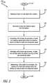
- FIG. 2is a flow chart for the disclosed method for battery monitoring, in accordance with at least one embodiment of the present disclosure.
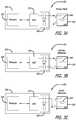
- FIG. 3Ais a schematic diagram showing a primary (cathode to anode referenced) configuration for the disclosed battery monitoring system, in accordance with at least one embodiment of the present disclosure.
- FIG. 3Bis a schematic diagram showing a cathode to case referenced configuration for the disclosed battery monitoring system, in accordance with at least one embodiment of the present disclosure.
- FIG. 3Cis a schematic diagram showing an anode to case referenced configuration for the disclosed battery monitoring system, in accordance with at least one embodiment of the present disclosure.
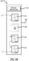
- FIG. 4Ais a schematic diagram showing a monitoring configuration for a plurality of battery cells for the disclosed battery monitoring system where the battery cells are connected in series, in accordance with at least one embodiment of the present disclosure.
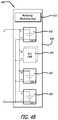
- FIG. 4Bis a schematic diagram showing a monitoring configuration for a plurality of battery cells for the disclosed battery monitoring system where the battery cells are connected in parallel, in accordance with at least one embodiment of the present disclosure.
- FIG. 5is a graph illustrating an exemplary baseline signal, in accordance with at least one embodiment of the present disclosure.
- FIG. 6is a graph showing an exemplary comparison signal, in accordance with at least one embodiment of the present disclosure.
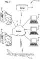
- FIG. 7is a schematic diagram of a network of data processing systems that may be employed by the disclosed battery monitoring system, in accordance with at least one embodiment of the present disclosure.
- FIG. 8is a schematic diagram of a data processing system that may be employed by the disclosed battery monitoring system, in accordance with at least one embodiment of the present disclosure.
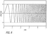
- FIG. 9is a graph illustrating an exemplary chirped signal, in accordance with at least one embodiment of the present disclosure.
- the methods and apparatus disclosed hereinprovide an operative in-situ battery monitoring system. Specifically, the system injects high-frequency test signals into a battery and receives reflectometry-based response signals.
- the response signalscomprise reflective signals, which have voltage levels that are in proportion to changes of the characteristic impedances of the conductive surfaces within the battery cell. If any of the voltage levels of the response signals exceeds the expected voltage levels of the response signals, this is an indication that the locations(s) of the reflection event(s) may be exhibiting an anomaly.
- batteriesare typically designed to have large capacities, with the more advanced chemistries based on Lithium-ion that enable higher energy densities with even higher charge/discharge characteristics than existing battery types, such as Nickel-metal-hydride or Nickel-Cadmium.
- This more reactive chemistrycan lead to electrolyte instabilities, especially at elevated temperatures.
- the battery state of charge (SOC)is usually determined by the battery cell voltage (CV) and may not completely reveal the current battery health and relative stability of the battery cells.
- the objective of the present disclosureis to use reflectometry to measure the relative in-situ radio frequency (RF) impedance behavior of the cathode-anode assemblies within the battery cells, in conjunction with temperature, CV, and SOC assessments to obtain a more complete, integrated-over time assessment of battery health.
- the goalis to identify the risk of a battery cell failure or short.
- the integrated effects of electrical and environmental exposure to batteriescan complicate the otherwise simple SOC assessment via CV measurements.
- the combined effects of manufacturing and environmentcan compromise the stability of a battery cell, thereby placing that battery cell and perhaps the other battery cells at risk for venting and/or fire.
- the physical assembly position and integritycan be assessed, presumably by sensing dendrite growth and/or by detecting foreign object debris (FOD) that could trigger a short-circuit condition within a monitored battery cell.
- FODforeign object debris
- Reflectometry-based measurementsare currently the preferred method to determine distance-to-fault (DFT) on an electrical wire.
- Reflectometry methodsinject radio or high-frequency tests signals on the wire-under-test (WUT). The signal voltage, from the test signals, reflects based in proportion to changes from the characteristic impedance of the WUT. If the measured reflection exceeds the expected reflection, additional scrutiny is required in the area of the reflection event.
- Electrically-conductive wirespresent themselves as “single-dimensional” with respect to radio or high-frequency electromagnetic wave transmission behavior, as there is circular symmetry about the wire and the insulating dielectric materials.
- FIG. 1is a schematic diagram of the disclosed system 100 for battery monitoring, in accordance with at least one embodiment of the present disclosure.
- monitoring electronics 170is shown to be injecting a test signal into a battery 140 .
- the test signalin one or more embodiments, is a radio- or high-frequency signal (e.g., 1 to 300 megahertz (MHz), or 300 MHz to 10 gigahertz (GHz)).
- the battery 140comprises at least one battery cell (not shown) and/or at least one battery case (not shown).
- a processor 110 in the monitoring electronics 170first determines the type of test signal to be injected into the battery 140 .
- the processor 110then sends instructions to a signal generator 120 to generate the test signal.
- the test signalis coded with a code, such as a pseudorandom number code or a gold code.
- the signal generator 120implements the processor's 110 instructions regarding the code into the test signal at the appropriate frequencies.
- the test signalis a spread-spectrum modulated signal.
- the test signalis a chirped signal.
- a chirped signalis a signal in which the frequency increases (up-chirp) or decreases (down-chirp) with time.
- FIG. 9shows an exemplary linear chirp waveform comprising a sinusoidal wave that increases in frequency linearly over time.
- the test signalis injected by a transmitter 130 into the battery 140 .
- the test signalis injected into at least one anode of at least one battery cell (not shown), at least one cathode of at least one battery cell (not shown), and/or at least one battery case (not shown).
- FIGS. 3A, 3B, and 3CA detailed discussion regarding the different injection configurations for the battery 140 is discussed in the description of FIGS. 3A, 3B, and 3C .
- a response signalis received from a receiver 150 .
- the response signalcomprises at least one reflected signal.
- the response signalwill help to indicate specific possible anomalies in the battery 140 .
- One possible anomaly in the battery 140is an open circuit.
- the response signalwill contain a reflected signal(s) with a higher voltage level due to a larger reflection off the open circuit.
- Another possible anomaly in the battery 140is a dendrite.
- the response signalwill contain a reflected signal(s) with a slightly lower voltage due to a smaller reflection off the local area of this anomaly.
- another possible anomaly in the batteryis a short circuit.
- the response signalwill contain a reflected signal(s) with a substantially lower voltage due to the absorption of the transmitted signal into the local area of this anomaly.
- the reflectometry signalincurs a time delay based on the time from the transmitter 130 to the anomaly plus the time for the reflected signal to return the receiver 150 .
- a decoder 160decodes the response signal. Then, the processor 110 compares the response signal with a baseline signal to produce a comparison signal. For this comparison, the processor 110 specifically compares of the code of the response signal with the code of the baseline signal to produce a code for the comparison signal.
- the baseline signalis a function of the expected voltage of the battery 140 , the expected temperature of the battery 140 , and/or the expected impedance profile for the battery 140 .
- the processor 110uses the comparison signal to detect (and identify) at least one anomaly within the battery 140 .
- the processor 110uses the comparison signal to determine the location of the anomaly in the battery 140 .
- the processor 110 of the monitoring electronics 170may be in communication (e.g., either by wire or wirelessly) with a display, which is used to display the signals (e.g., the response signal, the baseline signal, and/or the comparison signal).
- the displaymay be a computer display unit that is part of, for example, a desktop computer (similar to server 704 in FIG. 7 ) or a laptop computer (similar to client 710 in FIG. 7 ).
- FIG. 2is a flow chart for the disclosed method 200 for battery monitoring, in accordance with at least one embodiment of the present disclosure.
- At the start 210 of the method 200at least one test signal is injected into a battery 220 .
- At least one response signal from the batteryis received 230 .
- At least one processorcompares the response signal(s) with at least one baseline signal to produce at least one comparison signal 240 . Then, at least one processor detects at least one anomaly within the battery by using the comparison signal(s) 250 . Also, at least one processor determines the location of at least one anomaly within the battery by using the comparison signal(s) 260 . Then, the method 200 ends 270 .
- FIG. 3Ais a schematic diagram 300 showing the primary (cathode to anode referenced) configuration for the disclosed battery monitoring system, in accordance with at least one embodiment of the present disclosure.
- monitoring electronics 330is shown to be injecting a test signal into a battery cell 340 encompassed by a battery case 350 .
- a processor 360 in the monitoring electronics 330determines the type of test signal to be injected into the battery 340 .
- the processor 360then sends instructions to an application specific integrated circuit (ASIC) 370 to generate the test signal.
- the test signalmay be coded with a code, such as a pseudorandom number code or a gold code.
- the ASIC 370implements the processor's 360 instructions regarding the code into the test signal at the appropriate frequencies.
- the test signalmay be a spread-spectrum modulated signal, or in other embodiments, the test signal is a chirped signal.
- the test signalis injected by a transmitter of a transmitter/receiver circuit (T/R Ckt) 380 into the battery 340 .
- T/R Ckttransmitter/receiver circuit
- the test signalis shown to be injected into the cathode (denoted by a plus sign) of the battery cell 340 , and referenced through the anode (denoted by a minus sign) of the battery cell 340 .
- the transmitter/receiver circuit 380comprises capacitors, as is shown in the figure.
- a response signalis referenced from the anode of the battery cell 340 .
- a receiver of the transmitter/receiver circuit 380receives the response signal.
- the response signalcomprises at least one reflected signal.
- the ASIC 370decodes the response signal. Then, the processor 360 compares the response signal with a baseline signal to produce a comparison signal. The processor 360 then uses the comparison signal to detect (and identify) at least one anomaly within the battery cell 340 . In addition, the processor 360 uses the comparison signal to determine the location of the anomaly in the battery cell 340 .
- FIG. 3Bis a schematic diagram 310 showing a cathode to case referenced configuration for the disclosed battery monitoring system, in accordance with at least one embodiment of the present disclosure.
- This figureis the same as FIG. 3A except that this figure shows a different configuration for the injection of the test signal.
- the test signalis shown to be injected into the cathode of the battery cell 340 , and is referenced from the battery case 350 . It should be noted that this configuration requires that the battery case 350 be electrically conductive.
- FIG. 3Cis a schematic diagram 320 showing an anode to case referenced configuration for the disclosed battery monitoring system, in accordance with at least one embodiment of the present disclosure.
- This figureis the same as FIGS. 3A and 3B except that this figure shows a different configuration for the injection of the test signal.
- the test signalis shown to be injected into the anode of the battery cell 340 , and is referenced from the battery case 350 . It should be noted that this configuration requires that the battery case 350 be electrically conductive.
- FIG. 4Ais a schematic diagram 400 showing a monitoring configuration for a plurality of battery cells 420 for the disclosed battery monitoring system where the battery cells are connected in series, in accordance with at least one embodiment of the present disclosure.
- monitoring electronics 410are injecting a test signal into a plurality of battery cells 420 , which are housed along with the monitoring electronics 410 in a battery case 430 .
- the plurality of battery cells 420 in this figureare connected together in series.
- the operation of the monitoring electronics 410is the same as described in FIG. 3A .
- FIG. 4Bis a schematic diagram 440 showing a monitoring configuration for a plurality of battery cells 420 for the disclosed battery monitoring system where the battery cells are connected in parallel, in accordance with at least one embodiment of the present disclosure.
- the monitoring configuration depicted in FIG. 4Bis the same as the monitoring configuration shown in FIG. 4A except that the battery cells 420 are connected in parallel, instead of in series, as is shown in FIG. 4A .
- the battery cells 420may be connected together by a combination of series and parallel connections. Also, it should be noted that during testing, not all of the battery cells 420 need to be tested each time. For these cases, only one or some of the battery cells 420 may be tested each time.
- FIG. 5is a graph 500 illustrating an exemplary baseline signal 508 , in accordance with at least one embodiment of the present disclosure.
- Graph 500has a horizontal axis and a vertical axis.
- the horizontal accessis a distance axis 502 .
- Distance axis 502represents the distance away from the location of the battery cell (or the battery case) from which the test signal was injected. Points on graph 500 closer to the intersection point between distance axis 502 and the vertical axis represent a shorter distance from the physical location at which the test signal was injected. Likewise, points on graph 500 farther from the intersection point between distance axis 502 and the vertical axis represent a longer distance from the physical location at which the test signal was injected.
- the vertical axisis the signal voltage axis 504 .
- Signal voltage axis 504represents the strength of the baseline signal 508 .
- the strength of the baseline signal 508may correspond to an impedance change encountered by the test signal at a given location in the battery cell or the battery case. Points on graph 500 closer to the intersection between signal voltage axis 504 and distance axis 502 indicate a lower voltage, while points on graph 500 farther from the intersection between signal voltage axis 504 and distance axis 502 indicate a greater voltage.
- portion 510i.e. a high voltage spike
- the test signal injection pointrepresents the location at which the test signal enters (or is injected) into the battery cell or the battery case.
- Section 512 of the baseline signal 508illustrates a region of the reflection signature showing the RF impedance behavior of the cathode-anode structure of the battery.
- portion 514 of the baseline signal 508shows the impedance mismatch at the end of the cathode of the battery.
- FIG. 6is a graph 600 showing an exemplary comparison signal 608 , in accordance with at least one embodiment of the present disclosure.
- Graph 600has a horizontal axis and a vertical axis.
- the horizontal accessis a distance axis 602 .
- Distance axis 602represents the distance away from the location of the battery cell (or the battery case) from which the test signal was injected. Points on graph 600 closer to the intersection point between distance axis 602 and the vertical axis represent a shorter distance from the physical location at which the test signal was injected. Likewise, points on graph 600 farther from the intersection point between distance axis 602 and the vertical axis represent a longer distance from the physical location at which the test signal was injected.
- the vertical axisis the signal voltage axis 604 .
- Signal voltage axis 604represents the magnitude of the comparison signal 608 .
- the magnitude of the comparison signal 608corresponds to the magnitude of the difference of an impedance change encountered by the test signal at a given location in the battery cell or the battery case. Points on graph 600 closer to the intersection between signal voltage axis 604 and distance axis 602 indicate a lower magnitude (i.e. voltage), while points on graph 600 farther from the intersection between signal voltage axis 604 and distance axis 602 indicate a greater magnitude (i.e. voltage).
- the comparison signal 608 on graph 600is an example of the difference between the baseline signal 508 and the first sample signal measurement that is taken (not shown).
- the comparison signal 608is to be used to detect the change in the differences from the baseline signal 508 of graph 500 of FIG. 5 .
- multiple response signalsi.e. multiple sample signal measurements
- a gradual change in the difference in the signalsi.e. the difference between the baseline signal 508 and the response signals
- portion 610i.e. a small voltage difference
- portion 610i.e. a small voltage difference
- the test signal injection pointrepresents the location at which the test signal enters (or is injected) into the battery cell or the battery case.
- Section 612 of the comparison signal 608illustrates a region of interest that is monitored for trends of RF impedance changes over time. Trends, for example, of the signal lying below the distance axis (x-axis) 602 suggest shorting trends in the battery. And, trends, for example, of the signal lying above the signal voltage axis (y-axis) 604 suggest open circuit trends in the battery.
- portion 614 of the comparison signal 608shows a typical allowable difference of the impedance mismatch at the end of the cathode of the battery.
- FIGS. 7 and 8exemplary diagrams of data processing environments are provided in which embodiments of the present disclosure may be implemented. It should be appreciated that FIGS. 7 and 8 are only exemplary and are not intended to assert or imply any limitation with regard to the environments in which different embodiments may be implemented. Many modifications to the depicted environments may be made.
- FIG. 7is a schematic diagram of a network of data processing systems that may be employed by the disclosed battery monitoring system, in accordance with at least one embodiment of the present disclosure.
- Network data processing system 700is a network of computers in which embodiments of the disclosed battery monitoring system may be implemented.
- Network data processing system 700may be used to monitor for anomalies in the battery (e.g., a battery comprising at least one battery cell and/or at least one battery case) of, for example, an aircraft. Monitoring may be performed in any suitable aircraft manufacturing and service method. For example, monitoring for anomalies in a battery of an aircraft may be performed during component and subassembly manufacturing, in service, and/or maintenance and service.
- Network data processing system 700contains network 702 , which is the medium used to provide communications links between various devices and computers connected together within network data processing system 700 .
- Network 702may include connections, such as wire, wireless communication links, or fiber optic cables.
- server 704 and server 706connect to network 702 along with storage unit 708 .
- clients 710 , 712 , and 714connect to network 702 .
- These clients 710 , 712 , and 714may be, for example, personal computers or network computers.
- server 704provides data, such as boot files, operating system images, and applications to clients 710 , 712 , and 714 .
- Clients 710 , 712 , and 714are clients to server 704 in this example.
- Aircraft 716also is a client that may exchange information with clients 710 , 712 , and 714 .
- Aircraft 716also may exchange information with servers 704 and 706 .
- Aircraft 716may exchange data with different computers through a wireless communications link while in-flight or any other type of communications link while on the ground.
- server 704 , server 706 , client 710 , client 712 , and client 714may be computers.
- Network data processing system 700may include additional servers, clients, and other devices not shown.
- aircraft 716may be other types of vehicles or platforms that employ any type of sophisticated battery (i.e. a battery that has a high level of amp-hours and a high energy density chemistry) that tends to require maintenance and monitoring for degradation.
- client 710is used as a monitoring unit to inject test signals and receive response signals through a battery in aircraft 716 .
- Server 706may then be used to compare the response signals with baselines signals to produce comparison signals, which are used to determine if any anomalies are present in the battery.
- aircraft 716 , client 710 and/or server 706may contain parts of or the entirety of the monitoring unit.
- Aircraft 716may also have a monitoring unit located onboard aircraft 716 .
- Aircraft 716may transmit a response signal, a baseline signal, and/or a comparison signal to client 710 and/or server 706 , for example.
- Client 710 and/or server 706may be located at a facility of the manufacturer of aircraft 716 , an airline, or any other suitable location. Additionally, client 710 and/or server 706 may transmit and receive one or more requests and responses to aircraft 716 using network 702 .
- the requestsmay be requests to monitor the battery onboard aircraft 716 .
- the responsesmay be one or more response signals from the battery and/or alerts regarding the status of the battery health.
- network data processing system 700is the Internet with network 702 representing a worldwide collection of networks and gateways that use the Transmission Control Protocol/Internet Protocol (TCP/IP) suite of protocols to communicate with one another.
- network data processing system 700also may be implemented as a number of different types of networks, such as for example, an intranet, a local area network (LAN), or a wide area network (WAN).
- FIG. 7is intended as an example, and not as an architectural limitation for different embodiments.
- FIG. 8is a schematic diagram of a data processing system 800 that may be employed by the disclosed battery monitoring system, in accordance with at least one embodiment of the present disclosure.
- Data processing system 800is an example of a data processing system that may be used to implement servers and clients, such as server 704 and client 710 . Further, data processing system 800 is an example of a data processing system that may be found in aircraft 716 in FIG. 7 .
- data processing system 800includes communications fabric 802 , which provides communications between processor unit 804 , memory 806 , persistent storage 808 , communications unit 810 , input/output (I/O) unit 812 , and display 814 .
- communications fabric 802provides communications between processor unit 804 , memory 806 , persistent storage 808 , communications unit 810 , input/output (I/O) unit 812 , and display 814 .
- Processor unit 804serves to execute instructions for software that may be loaded into memory 806 .
- Processor unit 804may be a number of one or more processors or may be a multi-processor core, depending on the particular implementation. Further, processor unit 804 may be implemented using one or more heterogeneous processor systems, in which a main processor is present with secondary processors on a single chip. As another illustrative example, processor unit 804 may be a symmetric multi-processor system containing multiple processors of the same type.
- Memory 806 and persistent storage 808are examples of storage devices 816 .
- a storage deviceis any piece of hardware that is capable of storing information, such as, for example, without limitation, data, program code in functional form, and/or other suitable information either on a temporary basis and/or a permanent basis.
- Memory 806in these examples, may be, for example, a random access memory, or any other suitable volatile or non-volatile storage device.
- Persistent storage 808may take various forms, depending on the particular implementation.
- persistent storage 808may contain one or more components or devices.
- persistent storage 808may be a hard drive, a flash memory, a rewritable optical disk, a rewritable magnetic tape, or some combination of the above.
- the media used by persistent storage 808may be removable.
- a removable hard drivemay be used for persistent storage 808 .
- Communications unit 810in these examples, provides for communication with other data processing systems or devices.
- communications unit 810is a network interface card.
- Communications unit 810may provide communications through the use of either or both physical and wireless communications links.
- Input/output unit 812allows for the input and output of data with other devices that may be connected to data processing system 800 .
- input/output unit 812may provide a connection for user input through a keyboard, a mouse, and/or some other suitable input device. Further, input/output unit 812 may send output to a printer.
- Display 814provides a mechanism to display information to a user.
- Instructions for the operating system, applications, and/or programsmay be located in storage devices 816 , which are in communication with processor unit 804 through communications fabric 802 .
- the instructionsare in a functional form on persistent storage 808 . These instructions may be loaded into memory 806 for execution by processor unit 804 .
- the processes of the different embodimentsmay be performed by processor unit 804 using computer implemented instructions, which may be located in a memory, such as memory 806 .
- program codeIn the different embodiments, may be embodied on different physical or computer readable storage media, such as memory 806 or persistent storage 808 .
- Program code 818is located in a functional form on computer readable media 820 that is selectively removable and may be loaded onto or transferred to data processing system 800 for execution by processor unit 804 .
- Program code 818 and computer readable media 820form computer program product 822 .
- computer readable media 820may be computer readable storage media 824 or computer readable signal media 826 .
- Computer readable storage media 824may include, for example, an optical or magnetic disc that is inserted or placed into a drive or other device that is part of persistent storage 808 for transfer onto a storage device, such as a hard drive, that is part of persistent storage 808 .
- Computer readable storage media 824also may take the form of a persistent storage, such as a hard drive, a thumb drive, or a flash memory that is connected to data processing system 800 . In some instances, computer readable storage media 824 may not be removable from data processing system 800 .
- program code 818may be transferred to data processing system 800 using computer readable signal media 826 .
- Computer readable signal media 826may be, for example, a propagated data signal containing program code 818 .
- Computer readable signal media 826may be an electro-magnetic signal, an optical signal, and/or any other suitable type of signal. These signals may be transmitted over communications links, such as wireless communications links, an optical fiber cable, a coaxial cable, a wire, and/or any other suitable type of communications link.
- the communications link and/or the connectionmay be physical or wireless in the illustrative examples.
- the computer readable mediaalso may take the form of non-tangible media, such as communications links or wireless transmissions containing the program code.
- program code 818may be downloaded over a network to persistent storage 808 from another device or data processing system through computer readable signal media 826 for use within data processing system 800 .
- program code stored in a computer readable storage media in a server data processing systemmay be downloaded over a network from the server to data processing system 800 .
- the data processing system providing program code 818may be a server computer, a client computer, or some other device capable of storing and transmitting program code 818 .
- data processing system 800may include organic components integrated with inorganic components and/or may be comprised entirely of organic components excluding a human being.
- a storage devicemay be comprised of an organic semiconductor.
- a storage device in data processing system 800is any hardware apparatus that may store data.
- Memory 806 , persistent storage 808 , and computer readable media 820are examples of storage devices in a tangible form.
- a bus systemmay be used to implement communications fabric 802 and may be comprised of one or more buses, such as a system bus or an input/output bus.
- the bus systemmay be implemented using any suitable type of architecture that provides for a transfer of data between different components or devices attached to the bus system.
- a communications unitmay include one or more devices used to transmit and receive data, such as a modem or a network adapter.
- a memorymay be, for example, memory 806 or a cache such as found in an interface and memory controller hub that may be present in communications fabric 802 .
Landscapes
- Physics & Mathematics (AREA)
- General Physics & Mathematics (AREA)
- Engineering & Computer Science (AREA)
- Manufacturing & Machinery (AREA)
- Chemical & Material Sciences (AREA)
- Chemical Kinetics & Catalysis (AREA)
- Electrochemistry (AREA)
- General Chemical & Material Sciences (AREA)
- Power Engineering (AREA)
- Charge And Discharge Circuits For Batteries Or The Like (AREA)
- Secondary Cells (AREA)
- Tests Of Electric Status Of Batteries (AREA)
Abstract
Description
Claims (24)
Priority Applications (6)
| Application Number | Priority Date | Filing Date | Title |
|---|---|---|---|
| US13/856,989US10753979B2 (en) | 2013-04-04 | 2013-04-04 | In-situ battery monitoring system |
| CA2841597ACA2841597C (en) | 2013-04-04 | 2014-01-30 | In-situ battery monitoring system |
| EP14157600.9AEP2787360B1 (en) | 2013-04-04 | 2014-03-04 | In-situ battery monitoring system |
| RU2014109406ARU2649322C2 (en) | 2013-04-04 | 2014-03-12 | Local control system of battery |
| JP2014071153AJP6080130B2 (en) | 2013-04-04 | 2014-03-31 | In-situ battery monitoring system |
| CN201410131061.1ACN104101841B (en) | 2013-04-04 | 2014-04-02 | Battery monitoring system in situ |
Applications Claiming Priority (1)
| Application Number | Priority Date | Filing Date | Title |
|---|---|---|---|
| US13/856,989US10753979B2 (en) | 2013-04-04 | 2013-04-04 | In-situ battery monitoring system |
Publications (2)
| Publication Number | Publication Date |
|---|---|
| US20140300363A1 US20140300363A1 (en) | 2014-10-09 |
| US10753979B2true US10753979B2 (en) | 2020-08-25 |
Family
ID=50189610
Family Applications (1)
| Application Number | Title | Priority Date | Filing Date |
|---|---|---|---|
| US13/856,989Active2036-04-25US10753979B2 (en) | 2013-04-04 | 2013-04-04 | In-situ battery monitoring system |
Country Status (6)
| Country | Link |
|---|---|
| US (1) | US10753979B2 (en) |
| EP (1) | EP2787360B1 (en) |
| JP (1) | JP6080130B2 (en) |
| CN (1) | CN104101841B (en) |
| CA (1) | CA2841597C (en) |
| RU (1) | RU2649322C2 (en) |
Families Citing this family (9)
| Publication number | Priority date | Publication date | Assignee | Title |
|---|---|---|---|---|
| WO2017005904A1 (en)* | 2015-07-09 | 2017-01-12 | Lithium Balance A/S | System for providing an excitation signal to an electrochemical system and method therefor |
| CN109416389B (en)* | 2016-06-28 | 2021-06-29 | 亚德诺半导体国际无限责任公司 | Wireless sensor for battery system |
| CN106516158B (en)* | 2016-11-25 | 2020-03-31 | 中国人民解放军海军航空工程学院 | Signal-oriented airplane in-situ automatic test system and fault diagnosis method |
| CN110418962B (en)* | 2017-02-03 | 2022-02-11 | 奈克斯赛瑞斯创新控股有限责任公司 | Systems and methods for monitoring gas analytes |
| DE102019202155A1 (en)* | 2019-02-18 | 2020-08-20 | Audi Ag | Method for operating a battery of an at least partially electrically operated / driven functional device, corresponding battery and functional device |
| RU2741741C1 (en)* | 2020-06-09 | 2021-01-28 | Российская Федерация, от имени которой выступает Государственная корпорация по атомной энергии "Росатом" (Госкорпорация "Росатом") | Battery monitoring device |
| JP7347451B2 (en)* | 2021-01-13 | 2023-09-20 | 株式会社豊田中央研究所 | Detection device, management device and detection method |
| KR20230032724A (en) | 2021-08-31 | 2023-03-07 | 주식회사 엘지에너지솔루션 | Apparatus and method for detecting internal defects of battery cell using tdr |
| CN117517999B (en)* | 2024-01-08 | 2024-05-24 | 超耐斯(深圳)新能源集团有限公司 | Lithium battery cell detecting system based on artificial intelligence |
Citations (53)
| Publication number | Priority date | Publication date | Assignee | Title |
|---|---|---|---|---|
| US4053824A (en) | 1975-07-30 | 1977-10-11 | Compagnie Europeenne D'accumulateurs S.A. | Method and device for checking a storage battery |
| US4759034A (en)* | 1986-12-02 | 1988-07-19 | General Research Of Electronics, Inc. | Multi-step spread spectrum communication apparatus |
| JPH05326032A (en) | 1992-05-26 | 1993-12-10 | Fujitsu Ltd | Battery abnormality detection method |
| JPH06290817A (en) | 1993-04-01 | 1994-10-18 | Hitachi Ltd | Secondary battery device |
| US5949219A (en)* | 1998-07-24 | 1999-09-07 | The United States Of America As Represented By The United States Department Of Energy | Optical state-of-charge monitor for batteries |
| US6005842A (en)* | 1997-06-26 | 1999-12-21 | Northern Telecom Limited | Engineering order wire |
| US6225810B1 (en) | 1998-02-12 | 2001-05-01 | The Boeing Company | Loop resistance tester (LRT) for cable shield integrity |
| US20010033605A1 (en)* | 1998-08-27 | 2001-10-25 | Bertram Gunzelmann | Tracking method and configuration for carrying out the method |
| US20020147561A1 (en) | 2001-04-09 | 2002-10-10 | William Baracat | System and method for intelligent wire testing |
| US6532255B1 (en)* | 1998-09-17 | 2003-03-11 | Siemens Aktiengesellschaft | Method and arrangement for minimizing the autocorrelation error in the demodulation of a spread-spectrum signal subject to multipath propagation |
| US6717786B2 (en) | 2001-10-30 | 2004-04-06 | The Boeing Company | Automatic voltage source selector for circuit breakers utilizing electronics |
| US20040230385A1 (en)* | 2003-05-12 | 2004-11-18 | Bechhoefer Eric Robert | Wire fault detection |
| US20050151657A1 (en)* | 2002-06-19 | 2005-07-14 | Lockhart Bradley W. | Battery monitor with wireless remote communication |
| US6932621B2 (en) | 2003-03-21 | 2005-08-23 | The Boeing Company | Connector interface pad for structurally integrated wiring |
| US20050213867A1 (en) | 2004-03-29 | 2005-09-29 | Rajendran Veera P | Optical battery temperature monitoring system and method |
| US7005995B2 (en) | 2003-09-16 | 2006-02-28 | The Boeing Company | System and method for remotely detecting and locating damaged conductors in a power system |
| US7010441B2 (en)* | 2003-05-15 | 2006-03-07 | Telcordia Technologies, Inc. | Method and system for improved single-ended loop make-up identification |
| US7069163B2 (en) | 2002-04-23 | 2006-06-27 | Utah State University | Digital spread spectrum methods and apparatus for testing aircraft wiring |
| US7075309B2 (en) | 2004-03-08 | 2006-07-11 | Livewire Test Labs, Inc. | System and method to locate an anomaly of a conductor |
| US20060213766A1 (en)* | 2004-03-17 | 2006-09-28 | Kennecott Utah Copper Corporation | Wireless Monitoring of Two or More Electrolytic Cells Using One Monitoring Device |
| US7165200B2 (en) | 2004-02-04 | 2007-01-16 | University Of Utah Research Foundation | System and method for characterizing a signal path using a sub-chip sampler |
| US7215126B2 (en) | 2002-11-19 | 2007-05-08 | University Of Utah Research Foundation | Apparatus and method for testing a signal path from an injection point |
| US7250772B2 (en) | 2002-11-19 | 2007-07-31 | University Of Utah Research Foundation | Method and apparatus for characterizing a signal path carrying an operational signal |
| US7271596B2 (en) | 2002-11-19 | 2007-09-18 | University Of Utah Research Foundation | Method and system for testing a signal path having an operational signal |
| US7436641B2 (en) | 2004-10-26 | 2008-10-14 | The Boeing Company | Device and system for wireless communications with a circuit breaker |
| US7474228B2 (en)* | 2002-06-19 | 2009-01-06 | Tarma, Llc | Battery monitor |
| CN101498765A (en) | 2008-01-28 | 2009-08-05 | 昶懋国际有限公司 | Separated battery state alarm and small battery state detector thereof |
| US7580235B2 (en) | 2004-10-12 | 2009-08-25 | The Boeing Company | Systems and methods for monitoring and controlling circuit breakers |
| CN101573851A (en) | 2006-09-29 | 2009-11-04 | 捷通国际有限公司 | System and method for inductively charging a battery |
| US7622931B2 (en) | 2005-10-03 | 2009-11-24 | University Of Utah Research Foundation | Non-contact reflectometry system and method |
| US7656637B2 (en) | 2004-10-12 | 2010-02-02 | The Boeing Company | Power control system pseudo power-up, aircraft including the power control system and method of controlling power in an aircraft |
| US20100057511A1 (en) | 2008-08-27 | 2010-03-04 | Mansouri Ali R | Integrated autonomous fleet management using self-aware vehicles |
| US20100063754A1 (en) | 2008-09-11 | 2010-03-11 | Thomas Terrance L | Wire fault illumination and display |
| US20100134061A1 (en) | 2008-12-01 | 2010-06-03 | Ali Reza Mansouri | Corona phenomena detection |
| CN101740838A (en) | 2008-11-12 | 2010-06-16 | 凹凸电子(武汉)有限公司 | Battery pack, method for monitoring battery pack and electronic system |
| US20100211338A1 (en) | 2006-10-25 | 2010-08-19 | Nicolas Ravot | Method and device for analyzing electric cable networks using pseudo-random sequences |
| JP2010539657A (en) | 2007-09-14 | 2010-12-16 | エイ 123 システムズ,インク. | Lithium rechargeable cell with reference electrode for health monitoring |
| US7868621B2 (en) | 2008-03-04 | 2011-01-11 | Honeywell International Inc. | Power line communication based aircraft power distribution system with real time wiring integrity monitoring capability |
| US20110153235A1 (en) | 2009-12-23 | 2011-06-23 | The Boeing Company | Wire System Assessment |
| US7977949B2 (en) | 2008-08-22 | 2011-07-12 | The Boeing Company | Loop resistance tester control system |
| WO2011091444A1 (en) | 2010-01-25 | 2011-07-28 | Geneva Cleantech Inc. | Automatic detection of appliances |
| US20110181295A1 (en) | 2010-01-22 | 2011-07-28 | Livewire Test Labs, Inc. | Fault detection using combined reflectometry and electronic parameter measurement |
| US8022711B2 (en) | 2008-12-17 | 2011-09-20 | Hamilton Sundstrand Corporation | Wire fault locating in distributed power systems |
| US8043452B2 (en) | 2007-11-01 | 2011-10-25 | The Boeing Company | Multifunctional electromagnetic shielding |
| WO2012006189A2 (en) | 2010-06-29 | 2012-01-12 | Qualcomm Incorporated | Touchless sensing and gesture recognition using continuous wave ultrasound signals |
| KR20120030966A (en) | 2010-09-21 | 2012-03-29 | 닛산 지도우샤 가부시키가이샤 | Detect apparatus for state of battery interior |
| US20120074952A1 (en)* | 2010-09-24 | 2012-03-29 | Chappell Daniel K | Home network characterization method and system |
| US8406936B1 (en) | 2007-06-05 | 2013-03-26 | The Boeing Company | Modular battery network system with life-optimal power management |
| US20130154541A1 (en) | 2011-12-15 | 2013-06-20 | The Boeing Company | Autonomous Lithium-Ion Battery Protection |
| JP2013134120A (en) | 2011-12-26 | 2013-07-08 | Mitsubishi Heavy Ind Ltd | Battery system |
| US20130260188A1 (en) | 2012-03-29 | 2013-10-03 | Dwaine Coates | Method and apparatus for optimized battery life cycle management |
| JP2014059174A (en) | 2012-09-14 | 2014-04-03 | Mitsubishi Electric Corp | Impedance detection system, monitoring system, and lithium secondary battery with monitoring function based on such monitoring system |
| US8891218B2 (en) | 2012-10-12 | 2014-11-18 | The Boeing Company | Fault tolerant fail-safe link |
Family Cites Families (4)
| Publication number | Priority date | Publication date | Assignee | Title |
|---|---|---|---|---|
| JP3789696B2 (en)* | 1999-11-01 | 2006-06-28 | 三洋電機株式会社 | Battery electrolyte leak inspection apparatus and battery electrolyte leak inspection method |
| JP2001155784A (en)* | 1999-11-25 | 2001-06-08 | Fdk Corp | Battery pack communication device |
| US6580929B1 (en)* | 2000-09-27 | 2003-06-17 | Mitake Information Corporation | Mobile phone charger also functioning as a remote sound monitoring device |
| CN202813869U (en)* | 2012-07-02 | 2013-03-20 | 北京物资学院 | Solar wireless remote intelligent heat-insulated cold closet |
- 2013
- 2013-04-04USUS13/856,989patent/US10753979B2/enactiveActive
- 2014
- 2014-01-30CACA2841597Apatent/CA2841597C/enactiveActive
- 2014-03-04EPEP14157600.9Apatent/EP2787360B1/enactiveActive
- 2014-03-12RURU2014109406Apatent/RU2649322C2/enactive
- 2014-03-31JPJP2014071153Apatent/JP6080130B2/enactiveActive
- 2014-04-02CNCN201410131061.1Apatent/CN104101841B/enactiveActive
Patent Citations (56)
| Publication number | Priority date | Publication date | Assignee | Title |
|---|---|---|---|---|
| US4053824A (en) | 1975-07-30 | 1977-10-11 | Compagnie Europeenne D'accumulateurs S.A. | Method and device for checking a storage battery |
| US4759034A (en)* | 1986-12-02 | 1988-07-19 | General Research Of Electronics, Inc. | Multi-step spread spectrum communication apparatus |
| JPH05326032A (en) | 1992-05-26 | 1993-12-10 | Fujitsu Ltd | Battery abnormality detection method |
| JPH06290817A (en) | 1993-04-01 | 1994-10-18 | Hitachi Ltd | Secondary battery device |
| US6005842A (en)* | 1997-06-26 | 1999-12-21 | Northern Telecom Limited | Engineering order wire |
| US6225810B1 (en) | 1998-02-12 | 2001-05-01 | The Boeing Company | Loop resistance tester (LRT) for cable shield integrity |
| US5949219A (en)* | 1998-07-24 | 1999-09-07 | The United States Of America As Represented By The United States Department Of Energy | Optical state-of-charge monitor for batteries |
| US20010033605A1 (en)* | 1998-08-27 | 2001-10-25 | Bertram Gunzelmann | Tracking method and configuration for carrying out the method |
| US6532255B1 (en)* | 1998-09-17 | 2003-03-11 | Siemens Aktiengesellschaft | Method and arrangement for minimizing the autocorrelation error in the demodulation of a spread-spectrum signal subject to multipath propagation |
| US20020147561A1 (en) | 2001-04-09 | 2002-10-10 | William Baracat | System and method for intelligent wire testing |
| US6717786B2 (en) | 2001-10-30 | 2004-04-06 | The Boeing Company | Automatic voltage source selector for circuit breakers utilizing electronics |
| US7069163B2 (en) | 2002-04-23 | 2006-06-27 | Utah State University | Digital spread spectrum methods and apparatus for testing aircraft wiring |
| US20050151657A1 (en)* | 2002-06-19 | 2005-07-14 | Lockhart Bradley W. | Battery monitor with wireless remote communication |
| US7474228B2 (en)* | 2002-06-19 | 2009-01-06 | Tarma, Llc | Battery monitor |
| US7215126B2 (en) | 2002-11-19 | 2007-05-08 | University Of Utah Research Foundation | Apparatus and method for testing a signal path from an injection point |
| US7250772B2 (en) | 2002-11-19 | 2007-07-31 | University Of Utah Research Foundation | Method and apparatus for characterizing a signal path carrying an operational signal |
| US7271596B2 (en) | 2002-11-19 | 2007-09-18 | University Of Utah Research Foundation | Method and system for testing a signal path having an operational signal |
| US6932621B2 (en) | 2003-03-21 | 2005-08-23 | The Boeing Company | Connector interface pad for structurally integrated wiring |
| US20040230385A1 (en)* | 2003-05-12 | 2004-11-18 | Bechhoefer Eric Robert | Wire fault detection |
| US7010441B2 (en)* | 2003-05-15 | 2006-03-07 | Telcordia Technologies, Inc. | Method and system for improved single-ended loop make-up identification |
| US7005995B2 (en) | 2003-09-16 | 2006-02-28 | The Boeing Company | System and method for remotely detecting and locating damaged conductors in a power system |
| US7165200B2 (en) | 2004-02-04 | 2007-01-16 | University Of Utah Research Foundation | System and method for characterizing a signal path using a sub-chip sampler |
| US7075309B2 (en) | 2004-03-08 | 2006-07-11 | Livewire Test Labs, Inc. | System and method to locate an anomaly of a conductor |
| US20060213766A1 (en)* | 2004-03-17 | 2006-09-28 | Kennecott Utah Copper Corporation | Wireless Monitoring of Two or More Electrolytic Cells Using One Monitoring Device |
| US20050213867A1 (en) | 2004-03-29 | 2005-09-29 | Rajendran Veera P | Optical battery temperature monitoring system and method |
| US7656637B2 (en) | 2004-10-12 | 2010-02-02 | The Boeing Company | Power control system pseudo power-up, aircraft including the power control system and method of controlling power in an aircraft |
| US7580235B2 (en) | 2004-10-12 | 2009-08-25 | The Boeing Company | Systems and methods for monitoring and controlling circuit breakers |
| US7436641B2 (en) | 2004-10-26 | 2008-10-14 | The Boeing Company | Device and system for wireless communications with a circuit breaker |
| US7570470B2 (en) | 2004-10-26 | 2009-08-04 | The Boeing Company | Self-powered communications link for smart circuit breakers |
| US7622931B2 (en) | 2005-10-03 | 2009-11-24 | University Of Utah Research Foundation | Non-contact reflectometry system and method |
| CN101573851A (en) | 2006-09-29 | 2009-11-04 | 捷通国际有限公司 | System and method for inductively charging a battery |
| US20100211338A1 (en) | 2006-10-25 | 2010-08-19 | Nicolas Ravot | Method and device for analyzing electric cable networks using pseudo-random sequences |
| US8406936B1 (en) | 2007-06-05 | 2013-03-26 | The Boeing Company | Modular battery network system with life-optimal power management |
| JP2010539657A (en) | 2007-09-14 | 2010-12-16 | エイ 123 システムズ,インク. | Lithium rechargeable cell with reference electrode for health monitoring |
| US8043452B2 (en) | 2007-11-01 | 2011-10-25 | The Boeing Company | Multifunctional electromagnetic shielding |
| CN101498765A (en) | 2008-01-28 | 2009-08-05 | 昶懋国际有限公司 | Separated battery state alarm and small battery state detector thereof |
| US7868621B2 (en) | 2008-03-04 | 2011-01-11 | Honeywell International Inc. | Power line communication based aircraft power distribution system with real time wiring integrity monitoring capability |
| US7977949B2 (en) | 2008-08-22 | 2011-07-12 | The Boeing Company | Loop resistance tester control system |
| US20100057511A1 (en) | 2008-08-27 | 2010-03-04 | Mansouri Ali R | Integrated autonomous fleet management using self-aware vehicles |
| US20100063754A1 (en) | 2008-09-11 | 2010-03-11 | Thomas Terrance L | Wire fault illumination and display |
| CN101740838A (en) | 2008-11-12 | 2010-06-16 | 凹凸电子(武汉)有限公司 | Battery pack, method for monitoring battery pack and electronic system |
| US20100134061A1 (en) | 2008-12-01 | 2010-06-03 | Ali Reza Mansouri | Corona phenomena detection |
| US8022711B2 (en) | 2008-12-17 | 2011-09-20 | Hamilton Sundstrand Corporation | Wire fault locating in distributed power systems |
| US20110153235A1 (en) | 2009-12-23 | 2011-06-23 | The Boeing Company | Wire System Assessment |
| EP2343562A2 (en) | 2009-12-23 | 2011-07-13 | The Boeing Company | Wire system assessment |
| US20110181295A1 (en) | 2010-01-22 | 2011-07-28 | Livewire Test Labs, Inc. | Fault detection using combined reflectometry and electronic parameter measurement |
| WO2011091444A1 (en) | 2010-01-25 | 2011-07-28 | Geneva Cleantech Inc. | Automatic detection of appliances |
| WO2012006189A2 (en) | 2010-06-29 | 2012-01-12 | Qualcomm Incorporated | Touchless sensing and gesture recognition using continuous wave ultrasound signals |
| KR20120030966A (en) | 2010-09-21 | 2012-03-29 | 닛산 지도우샤 가부시키가이샤 | Detect apparatus for state of battery interior |
| JP2012069267A (en) | 2010-09-21 | 2012-04-05 | Nissan Motor Co Ltd | Battery internal state detection device |
| US20120074952A1 (en)* | 2010-09-24 | 2012-03-29 | Chappell Daniel K | Home network characterization method and system |
| US20130154541A1 (en) | 2011-12-15 | 2013-06-20 | The Boeing Company | Autonomous Lithium-Ion Battery Protection |
| JP2013134120A (en) | 2011-12-26 | 2013-07-08 | Mitsubishi Heavy Ind Ltd | Battery system |
| US20130260188A1 (en) | 2012-03-29 | 2013-10-03 | Dwaine Coates | Method and apparatus for optimized battery life cycle management |
| JP2014059174A (en) | 2012-09-14 | 2014-04-03 | Mitsubishi Electric Corp | Impedance detection system, monitoring system, and lithium secondary battery with monitoring function based on such monitoring system |
| US8891218B2 (en) | 2012-10-12 | 2014-11-18 | The Boeing Company | Fault tolerant fail-safe link |
Non-Patent Citations (13)
| Title |
|---|
| ADRIEN LELONG ; MARC O. CARRION: "On line wire diagnosis using Multicarrier Time Domain Reflectometry for fault location", SENSORS, 2009 IEEE, IEEE, PISCATAWAY, NJ, USA, 25 October 2009 (2009-10-25), Piscataway, NJ, USA, pages 751 - 754, XP031618950, ISBN: 978-1-4244-4548-6 |
| Adrien Lelong, et al., "On Line Wire Diagnosis using Multicarrier Time Domain Reflectometry for Fault Location", Sensors, 2009 IEEE, IEEE, Piscataway, NJ, USA, Oct. 25, 2009, pp. 751-754. XP031618950, ISBN: 978-1-4244-4548-6, the whole document. |
| Blumer, et al., "Advanced Vehicle Wire Health for the 21st Century", Boeing Publication, 2004. |
| Blumer, John, "Advanced Vehicle Wire Health for the 21st Century," SAE Technical Paper Series, Nov. 2004, pp. 1-8, 2004-01-3159, SAE International, Warrendale, Pennsylvania/USA. |
| Extended European Search Report, Application Ser. No. 14157600.9-1560, dated Jul. 31, 2014. |
| Lelong et al., "On Line Wire Diagnosis Using Multicarrier Time Domain Reflectometry for Fault Location," Sensors, 2009 IEEE, IEEE, Piscataway, NJ, USA, Oct. 25, 2009, pp. 751-754. XP031618950, ISBN: 978-1-4244-4548-6. |
| Office Action from Japanese Patent Office, Patent Application No. JP 2014/071153, dated Apr. 18, 2016. |
| Office Action from Japanese Patent Office, Patent Application No. JP 2014-071153, dated Apr. 18, 2016. (English translation attached). |
| Office Action from Japanese Patent Office, Patent Application No. JP 2014-071153, dated Oct. 26, 2015.(English translation). |
| SAE Aerospace, "(R) ARC Fault Circuit Breaker 9AFCB), Aircraft, Trip-Free Single Phase and Three Phase 115 VAC, 400 Hz—Constant Frequency," SAE Technical Report, Dec. 2009, pp. 1-64, AS5692A, SAE International, Warrendale, Pennsylvania/USA. |
| SAE Aerospace, "ARC Fault Circuit Breaker 9AFCB), Aircraft, Trip-Free 28 VDC," SAE Technical Report, Jun. 2012, pp. 1-60, AS6019, SAE International, Warrendale, Pennyslvania/USA. |
| SAE Aerospace, "Solid State Power Controller, General Standard for," SAE Technical Report, Jul. 2007, pp. 1-32, AS4805, SAE International, Warrendale, Pennsylvania/USA. |
| The Next Generation of DSL Can Pump 1Gbps Through Copper Phone Lines <http://gizmodo.com/the-next-generation-of-dsl-can-pump-1gbps-through-coppe-1484256467>.* |
Also Published As
| Publication number | Publication date |
|---|---|
| CA2841597A1 (en) | 2014-10-04 |
| JP2014202754A (en) | 2014-10-27 |
| CN104101841A (en) | 2014-10-15 |
| EP2787360B1 (en) | 2022-06-29 |
| CA2841597C (en) | 2016-10-04 |
| RU2014109406A (en) | 2015-09-20 |
| RU2649322C2 (en) | 2018-04-02 |
| JP6080130B2 (en) | 2017-02-15 |
| CN104101841B (en) | 2019-07-02 |
| EP2787360A1 (en) | 2014-10-08 |
| US20140300363A1 (en) | 2014-10-09 |
Similar Documents
| Publication | Publication Date | Title |
|---|---|---|
| US10753979B2 (en) | In-situ battery monitoring system | |
| EP2221626B1 (en) | A method for testing a power distribution system an a power distribution system analyser device | |
| US10818981B2 (en) | Battery internal temperature sensing battery management system | |
| Akbari et al. | Challenges in calibration of the measurement of partial discharges at ultrahigh frequencies in power transformers | |
| EP2725367B1 (en) | Method and device for monitoring partial discharges | |
| de Paulis et al. | Performance improvements of wire fault diagnosis approach based on time‐domain reflectometry | |
| CN103063939A (en) | Ground cascade system external radio frequency electromagnetic environment test method | |
| Rahbarimagham et al. | Determination of transformer HV winding axial displacement occurrence, direction, and extent using time‐domain analysis of UWB signals | |
| Rahbarimagham et al. | Determination of transformer HV winding axial displacement extent using hyperbolic method–a feasibility study | |
| Crawford et al. | Generation of EM susceptibility test fields using a large absorber-loaded TEM cell | |
| Alam | Applications of electromagnetic principles in the design and development of proximity wireless sensors | |
| JP6032025B2 (en) | Storage battery state detection method and storage battery state detection device | |
| Romero et al. | Prediction of the maximum electric field level inside a metallic cavity using a quality factor estimation | |
| Balali et al. | Development of multidimensional monitoring systems for power transformers by integrating special UHF partial discharge detectors | |
| Andrieu et al. | Radiated susceptibility tests in thermal vacuum chambers working as reverberation chambers | |
| Brewer | EMC failures happen. | |
| Lee et al. | Diagnosis of cables in nuclear power plants using joint time-frequency domain reflectometry | |
| US20250314687A1 (en) | Conductor fault detection and localization | |
| Hager | On Applying the Electromagnetic Probability-of-Effect Assessment Tool to Hazards of Electromagnetic Radiation to Ordnance | |
| Buta et al. | Stripline measurements in automotive EMC: A case study | |
| Aliyali et al. | Non-destructive Testing of Generic EUT Based on Measured Absorption Cross Section Ratio | |
| Chen et al. | A Method for Predicting Coupling Laws of UWB EMP to Millimeter Wave Detector | |
| Stant et al. | Evaluating residual errors in waveguide VNAs from microwave to submillimetre‐wave frequencies | |
| CN120779152A (en) | Radio frequency path line loss measuring method and device | |
| Saeed et al. | Advancements in Temperature Sensing Technologies for Lithium-Ion Batteries in Electric Vehicle Thermal Management Systems: A Comprehensive Review |
Legal Events
| Date | Code | Title | Description |
|---|---|---|---|
| AS | Assignment | Owner name:THE BOEING COMPANY, ILLINOIS Free format text:ASSIGNMENT OF ASSIGNORS INTEREST;ASSIGNORS:THOMAS, TERRANCE L.;SCHAFFNER, LOWELL W.;BOURMAND, MORI M.;SIGNING DATES FROM 20130325 TO 20130326;REEL/FRAME:030154/0948 | |
| STPP | Information on status: patent application and granting procedure in general | Free format text:RESPONSE TO NON-FINAL OFFICE ACTION ENTERED AND FORWARDED TO EXAMINER | |
| STPP | Information on status: patent application and granting procedure in general | Free format text:NON FINAL ACTION MAILED | |
| STPP | Information on status: patent application and granting procedure in general | Free format text:RESPONSE TO NON-FINAL OFFICE ACTION ENTERED AND FORWARDED TO EXAMINER | |
| STPP | Information on status: patent application and granting procedure in general | Free format text:EX PARTE QUAYLE ACTION MAILED | |
| STPP | Information on status: patent application and granting procedure in general | Free format text:NOTICE OF ALLOWANCE MAILED -- APPLICATION RECEIVED IN OFFICE OF PUBLICATIONS | |
| STPP | Information on status: patent application and granting procedure in general | Free format text:NOTICE OF ALLOWANCE MAILED -- APPLICATION RECEIVED IN OFFICE OF PUBLICATIONS | |
| STPP | Information on status: patent application and granting procedure in general | Free format text:NOTICE OF ALLOWANCE MAILED -- APPLICATION RECEIVED IN OFFICE OF PUBLICATIONS | |
| STPP | Information on status: patent application and granting procedure in general | Free format text:PUBLICATIONS -- ISSUE FEE PAYMENT VERIFIED | |
| STCF | Information on status: patent grant | Free format text:PATENTED CASE | |
| MAFP | Maintenance fee payment | Free format text:PAYMENT OF MAINTENANCE FEE, 4TH YEAR, LARGE ENTITY (ORIGINAL EVENT CODE: M1551); ENTITY STATUS OF PATENT OWNER: LARGE ENTITY Year of fee payment:4 |