US10753823B2 - Dynamic characterization system for measuring a dynamic response - Google Patents
Dynamic characterization system for measuring a dynamic responseDownload PDFInfo
- Publication number
- US10753823B2 US10753823B2US15/729,579US201715729579AUS10753823B2US 10753823 B2US10753823 B2US 10753823B2US 201715729579 AUS201715729579 AUS 201715729579AUS 10753823 B2US10753823 B2US 10753823B2
- Authority
- US
- United States
- Prior art keywords
- controller
- signal
- accelerometer
- casing
- excitation signal
- Prior art date
- Legal status (The legal status is an assumption and is not a legal conclusion. Google has not performed a legal analysis and makes no representation as to the accuracy of the status listed.)
- Active, expires
Links
- 238000012512characterization methodMethods0.000titleclaimsdescription10
- 230000005284excitationEffects0.000claimsabstractdescription49
- 238000004891communicationMethods0.000claimsabstractdescription20
- 238000003754machiningMethods0.000claimsdescription13
- 238000005259measurementMethods0.000claimsdescription3
- 238000004458analytical methodMethods0.000description11
- 238000000034methodMethods0.000description3
- 238000012423maintenanceMethods0.000description2
- 230000001133accelerationEffects0.000description1
- 229910052782aluminiumInorganic materials0.000description1
- XAGFODPZIPBFFR-UHFFFAOYSA-NaluminiumChemical compound[Al]XAGFODPZIPBFFR-UHFFFAOYSA-N0.000description1
- 239000003990capacitorSubstances0.000description1
- 230000007423decreaseEffects0.000description1
- 238000010586diagramMethods0.000description1
- 238000005058metal castingMethods0.000description1
- 230000000737periodic effectEffects0.000description1
- 238000005316response functionMethods0.000description1
- 239000000126substanceSubstances0.000description1
- 238000012360testing methodMethods0.000description1
Images


Classifications
- G—PHYSICS
- G05—CONTROLLING; REGULATING
- G05B—CONTROL OR REGULATING SYSTEMS IN GENERAL; FUNCTIONAL ELEMENTS OF SUCH SYSTEMS; MONITORING OR TESTING ARRANGEMENTS FOR SUCH SYSTEMS OR ELEMENTS
- G05B19/00—Programme-control systems
- G05B19/02—Programme-control systems electric
- G05B19/18—Numerical control [NC], i.e. automatically operating machines, in particular machine tools, e.g. in a manufacturing environment, so as to execute positioning, movement or co-ordinated operations by means of programme data in numerical form
- G05B19/401—Numerical control [NC], i.e. automatically operating machines, in particular machine tools, e.g. in a manufacturing environment, so as to execute positioning, movement or co-ordinated operations by means of programme data in numerical form characterised by control arrangements for measuring, e.g. calibration and initialisation, measuring workpiece for machining purposes
- G—PHYSICS
- G01—MEASURING; TESTING
- G01M—TESTING STATIC OR DYNAMIC BALANCE OF MACHINES OR STRUCTURES; TESTING OF STRUCTURES OR APPARATUS, NOT OTHERWISE PROVIDED FOR
- G01M7/00—Vibration-testing of structures; Shock-testing of structures
- G01M7/02—Vibration-testing by means of a shake table
- G01M7/022—Vibration control arrangements, e.g. for generating random vibrations
- G—PHYSICS
- G01—MEASURING; TESTING
- G01H—MEASUREMENT OF MECHANICAL VIBRATIONS OR ULTRASONIC, SONIC OR INFRASONIC WAVES
- G01H1/00—Measuring characteristics of vibrations in solids by using direct conduction to the detector
- G01H1/003—Measuring characteristics of vibrations in solids by using direct conduction to the detector of rotating machines
- G—PHYSICS
- G01—MEASURING; TESTING
- G01M—TESTING STATIC OR DYNAMIC BALANCE OF MACHINES OR STRUCTURES; TESTING OF STRUCTURES OR APPARATUS, NOT OTHERWISE PROVIDED FOR
- G01M7/00—Vibration-testing of structures; Shock-testing of structures
- G01M7/02—Vibration-testing by means of a shake table
- G01M7/025—Measuring arrangements
- B—PERFORMING OPERATIONS; TRANSPORTING
- B23—MACHINE TOOLS; METAL-WORKING NOT OTHERWISE PROVIDED FOR
- B23Q—DETAILS, COMPONENTS, OR ACCESSORIES FOR MACHINE TOOLS, e.g. ARRANGEMENTS FOR COPYING OR CONTROLLING; MACHINE TOOLS IN GENERAL CHARACTERISED BY THE CONSTRUCTION OF PARTICULAR DETAILS OR COMPONENTS; COMBINATIONS OR ASSOCIATIONS OF METAL-WORKING MACHINES, NOT DIRECTED TO A PARTICULAR RESULT
- B23Q15/00—Automatic control or regulation of feed movement, cutting velocity or position of tool or work
- B23Q15/007—Automatic control or regulation of feed movement, cutting velocity or position of tool or work while the tool acts upon the workpiece
- B—PERFORMING OPERATIONS; TRANSPORTING
- B23—MACHINE TOOLS; METAL-WORKING NOT OTHERWISE PROVIDED FOR
- B23Q—DETAILS, COMPONENTS, OR ACCESSORIES FOR MACHINE TOOLS, e.g. ARRANGEMENTS FOR COPYING OR CONTROLLING; MACHINE TOOLS IN GENERAL CHARACTERISED BY THE CONSTRUCTION OF PARTICULAR DETAILS OR COMPONENTS; COMBINATIONS OR ASSOCIATIONS OF METAL-WORKING MACHINES, NOT DIRECTED TO A PARTICULAR RESULT
- B23Q17/00—Arrangements for observing, indicating or measuring on machine tools
- B23Q17/12—Arrangements for observing, indicating or measuring on machine tools for indicating or measuring vibration
- B—PERFORMING OPERATIONS; TRANSPORTING
- B23—MACHINE TOOLS; METAL-WORKING NOT OTHERWISE PROVIDED FOR
- B23Q—DETAILS, COMPONENTS, OR ACCESSORIES FOR MACHINE TOOLS, e.g. ARRANGEMENTS FOR COPYING OR CONTROLLING; MACHINE TOOLS IN GENERAL CHARACTERISED BY THE CONSTRUCTION OF PARTICULAR DETAILS OR COMPONENTS; COMBINATIONS OR ASSOCIATIONS OF METAL-WORKING MACHINES, NOT DIRECTED TO A PARTICULAR RESULT
- B23Q2717/00—Arrangements for indicating or measuring
- G—PHYSICS
- G05—CONTROLLING; REGULATING
- G05B—CONTROL OR REGULATING SYSTEMS IN GENERAL; FUNCTIONAL ELEMENTS OF SUCH SYSTEMS; MONITORING OR TESTING ARRANGEMENTS FOR SUCH SYSTEMS OR ELEMENTS
- G05B2219/00—Program-control systems
- G05B2219/30—Nc systems
- G05B2219/35—Nc in input of data, input till input file format
- G05B2219/35026—Design of machine tool, of cnc machine
Definitions
- the present disclosurerelates to a system for measuring a dynamic response of a machine.
- Computer numeric control (CNC) machinesare operable to perform high speed machining of workpieces, such as aluminum blocks, to form a part.
- CNCComputer numeric control
- workpiecessuch as aluminum blocks
- structural dynamics of the machinecan become a concern for preventing excessive or unstable vibration.
- An existing condition indicator analysis box (CIAB) systemmeasures vibrations during cutting, but cannot be used to determine the machine structural dynamics (i.e., natural frequencies and vibration modes).
- the present disclosureis directed to a dynamic characterization system that includes a vibration mechanism operable to generate an excitation signal, an accelerometer, a controller including a communication interface, and a casing.
- the accelerometeris operable to measure dynamic energy in response to the excitation signal and output a dynamic response signal indicative of the dynamic energy.
- the controlleris configured to operate the vibration mechanism to output the excitation signal and transmit a vibration input signal based on the excitation signal by way of the communication interface.
- the casinghouses the vibration mechanism and the controller.
- the casinghouses the accelerometer.
- the controllertransmits a vibration signal based on the dynamic response signal from the accelerometer by way of the communication interface.
- the accelerometeris located separately from the casing.
- the dynamic characterization systemfurther comprises a power source supplying power to at least one of the vibration mechanism or the controller, and the casing houses the power source.
- the power sourceis a turbine generator.
- the vibration mechanismis piezoelectric actuator.
- the communication interfaceincludes a wireless transceiver.
- the vibration mechanismis operable to output different excitation signals.
- the present disclosureis directed toward a dynamic characterization system for measuring dynamic response of an object.
- the systemincludes a piezoelectric actuator operable to generate an excitation signal, an accelerometer, a controller including a wireless transceiver, and a casing.
- the accelerometeris operable to measure dynamic energy in response to the excitation signal and generate a dynamic response signal indicative of the dynamic energy.
- the casingis configured to attach and detach from the object.
- the casingfurther houses the vibration mechanism and the controller.
- the controlleris configured to operate the piezoelectric actuator to output the excitation signal and output data based on the excitation signal by way of the wireless transceiver.
- systemfurther comprises a power source supplying power to the vibration mechanism and the controller.
- the casinghouses the accelerometer and the accelerometer outputs the dynamic response signal to the controller.
- the controlleris configured to filter the dynamic response signal from the accelerometer and output data indicative of the filtered dynamic response signal using the wireless transceiver.
- the controllertransposes the dynamic response signal from a measured location to a desired location.
- the accelerometeris positioned on the object at a location separate from the casing.
- the present disclosureis directed toward a system for measuring dynamic response of a machine.
- the systemcomprises a piezoelectric actuator operable to generate an excitation signal, an accelerometer, a controller, and a casing.
- the accelerometeris operable to output a dynamic response signal indicative of dynamic energy of the machine.
- the controlleris configured to operate the piezoelectric actuator to output the excitation signal and output data indicative of the excitation signal.
- the casinghouses the piezoelectric actuator and the controller and configured to attach to the machine.
- the casinghouses the accelerometer.
- the accelerometeris positioned on the machine separate from the casing.
- systemfurther comprises a turbine generator for supplying power to at least one of the controller or the piezoelectric actuator.
- FIG. 1illustrates a computer numeric control (CNC) machine system equipped with a dynamic characterization (DC) system in accordance with the teachings of the present disclosure
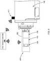
- FIG. 2illustrates one form of a DC system positioned at a spindle of the CNC machine in accordance with the teachings of the present disclosure
- FIG. 3is a block diagram of a DC controller of the DC system in accordance with the teachings of the present disclosure.
- FIG. 4illustrates another form of a DC system positioned at the spindle in accordance with the teachings of the present disclosure.
- a computer numeric control (CNC) machine system 100(“CNC system”, hereinafter) is equipped with a dynamic characterization (DC) system 102 of the present disclosure.
- the CNC system 100includes a CNC system controller 104 and a multi-axis CNC machining center 106 (“CNC machine” hereinafter) that is operable to form a part (e.g., an engine block) out of a workpiece 107 (e.g., metal casting).
- the CNC machine 106includes a spindle 108 and a tool (not shown) attached to an end of the spindle 108 .
- the toolis selected from multiple tools housed in a tool magazine 112 .
- the spindle 108 and/or the workpieceare moveable relative to each other along multiple axes, such that the spindle 108 aligns with a section of the workpiece 107 that is to be machined.
- the teachings of the present disclosureare applicable to other machines, and should not be limited to the CNC system 100 depicted.
- the CNC system controller 104is configured to operate the CNC machine 106 using one or more pre-stored programs. Accordingly, along with other components of the CNC machine 106 , the CNC system controller 104 controls the torque, position, orientation, and other operation parameters of the spindle 108 in order to form the part.
- the CNC system controller 104may be accessible by an operator via a user interface 111 .
- the CNC system controller 104is also configured to perform diagnostics on the CNC system 100 to ensure the system 100 is operating within certain parameters.
- the CNC system controller 104uses the DC system 102 of the present disclosure, the CNC system controller 104 performs a vibrational analysis of the CNC machine 106 to determine structural dynamics of the machine 106 .
- the DC system 102measures a dynamic energy of the CNC machine 106 in response to a controlled excitation signal generated by the DC system 102 .
- the CNC system controller 104Based on the data received, the CNC system controller 104 performs diagnostics to determine if the machine is operating within predefined parameters.
- the dynamic characterization system 102includes a casing 202 , a vibration mechanism 204 , a power supply 206 , an accelerometer 208 , and a dynamic characterization (DC) controller 210 .
- the casing 202houses the vibration mechanism 204 , the power supply 206 , the accelerometer 208 , and the DC controller 210 .
- the casing 202is configured to interface with the spindle 108 , so that the DC system 102 is readily attachable and detachable from the spindle 108 .
- the DC system 102may be stored in the tool magazine 112 of the CNC machine 106 , and in the event a vibrational analysis of the is to be performed, the CNC system controller 104 operates the CNC machine 106 to retrieve the DC system 102 from the tool magazine 112 and attach the system 102 to the spindle 108 .
- the DC system 102is positioned on the CNC machine 106 by an operator and is attachable to different locations along the CNC machine 106 . Accordingly, the physical configuration of the casing 202 may be altered based on the environment in which the DC system 102 is utilized.
- the vibration mechanism 204is operable to generate a predefined excitation signal for causing a dynamic response from the spindle 108 .
- the vibration mechanism 204is a piezoelectric actuator that is operable by the DC controller 210 .
- the vibration mechanism 204is an unbalanced mass that is mounted on the spindle to generate the excitation signal (i.e., input force).
- the DC system 102can deliver more energy to excite heavier components of the CNC machine 106 at frequencies related to the spindle 108 rotational speed.
- the power supply 206provides power to one or more components of the DC system 102 .
- the power supply 206supplies power to at least one of the DC controller 210 , the vibration mechanism 204 , and/or the accelerometer 208 .
- the power supply 206is a turbine generator that converts mechanical energy from the spindle, such as compressed air, to electrical energy.
- Other power supplies, such as a battery,are also within the scope of the present disclosure.
- the accelerometer 208measures dynamic energy (i.e., acceleration) along one or more axes in response to the excitation signal. More particularly, the excitation signal generated by the vibration mechanism 204 causes vibrations along the spindle 108 , and the accelerometer 208 measures the intensity of the vibration. In one form, the accelerometer 208 transmits data indicative of the dynamic energy of the spindle 108 as a dynamic response signal to the DC controller 210 . In other forms, the accelerometer may output the signal to the CNC system controller 104 , as described below.
- the DC controller 210is configured to control the operation of the vibration mechanism 204 and communicate with the CNC system controller 104 of the CNC system 100 .
- the DC controller 210includes a communication interface 302 , a vibration control module 304 , and a signal analysis module 306 .
- the DC controller 210includes electronic components, such as a microcontroller, filters (e.g., fast Fourier Transform chip), a transceiver, a capacitor for holding charge, and other suitable electronics for performing the various functions described herein.
- the communication interface 302establishes communication with external systems, such as the CNC system controller 104 .
- the communication interface 302includes a Bluetooth transceiver for establishing wireless communication using Bluetooth protocol.
- the communication interface 302may utilize other wireless communication protocols, such as Wi-Fi, radio frequency communication, and Zigbee, and should not be limited to Bluetooth protocol.
- the vibration control module 304controls the vibration mechanism 204 to have the vibration mechanism 204 generate the excitation signal, which may also be referred to as a input force.
- the vibration control module 304may be configured in various suitable ways for outputting the excitation signal.
- the vibration control module 304stores one or more signal profiles and selects the excitation signal from among the one or more signal profiles based on a command from the CNC system controller 104 , which identifies a desired signal profile of the excitation signal.
- the vibration control module 304is programmed to select certain signal profiles once power is received to the DC controller 210 , and thus, no further instruction is needed from the CNC system controller 104 .
- the excitation signalacts as an input force that causes vibration (e.g., dynamic energy) along the CNC machine 106 .
- the excitation signalincludes, but is not limited to, a sine waveform having a set frequency or a chirp signal in which the frequency changes (i.e., increases or decreases) with time. Since the excitation signal is based on a known signal profile, the input force applied to the CNC machine is consistent and not subject to operator error.
- the signal analysis module 306transmits signals indicative of the excitation signal and the dynamic response signal from the accelerometer 208 .
- the signal analysis module 306is configured to transform the excitation signal as a frequency domain signal and transmits the corresponding signal as a vibration input signal to the CNC system controller 104 by way of the communication interface 302 .
- the signal analysis module 306is configured to transform the dynamic response signal from the accelerometer 208 to a frequency domain signal and further, filters the transformed signal. That is, the transformed signal is transposed from its measured location (i.e., position of the accelerometer) to a desired location (e.g., an end of the spindle). The filtered signal is then transmitted to the CNC system controller 104 as a vibration signal by way of the communication interface 302 .
- the DC system 102is stored in the tool magazine 112 of the CNC machine 106 , and the CNC system controller 104 operates the CNC machine 106 to have the machine 106 retrieve the DC system 102 when a vibrational analysis of the CNC machine 106 is to be performed.
- the system controller 104when the power supply is a turbine generator, the system controller 104 outputs air from the spindle 108 to drive the turbine generator and thus, supply power to the components of the DC system 102 .
- the DC controller 210operates the vibration mechanism 204 to generate the excitation signal, and the accelerometer 208 measures vibrations of the CNC machine.
- the DC controller 210transmits data to the CNC system controller 104 based on the excitation signal and the dynamic response signal from the accelerometer 208 .
- the CNC system controller 104assesses the stability of the machine.
- the CNC system controllerperforms a frequency response function (FRF) measurement to determine stability lobes of the CNC machine 106 .
- FPFfrequency response function
- Other possible analysis performed by the CNC system controller 104 using the data from the DC system 102is also within the scope present disclosure.
- the CNC system controller 104operates the CNC machine 106 to have the DC system 102 placed back in the tool magazine 112 .
- Other operations and/or methods of using the DC system 102are also within the scope of the present disclosure. For example, an operator may position the DC system at other locations of the CNC machine 106 to measure the dynamic response of the CNC machine 106 .
- the DC system 102 of the present disclosureincludes a dedicated accelerometer for measuring the dynamic energy of the CNC machine 106 .
- a DC systemis configured to utilize an accelerometer of the CNC machine 106 .
- a DC system 402includes the casing 202 , the vibration mechanism 204 , a power supply 206 , and a DC controller 410 . Similar to the DC controller 210 , the DC controller 410 is configured to operate the vibration mechanism 204 and transmit data indicative of the excitation signal to the CNC system controller 104 .
- the CNC machine 106includes an accelerometer 412 disposed on the spindle 108 for measuring the dynamic energy of the CNC machine 106 .
- the accelerometer 412provides data indicative of the dynamic energy during normal machining operation and/or during diagnostics performed by the CNC system controller 104 .
- the DC system 402is further simplified.
- the DC controller 410is configured to provide data regarding the excitation signal and is not required to process the signal from the accelerometer 412 .
- the CNC systemreceives machine dynamics based on known force inputs (i.e., predetermined excitation signal) and not on an operator's experience. Furthermore, the CNC system 100 can perform the vibrational analysis without having to be offline. That is, the CNC system 100 can obtain the dynamic response of the CNC machine 106 automatically without the assistance of an operator.
- the CNC systemis able to characterize an entire work envelope, and not just the dynamic response at a few fixed configuration, which may not include structural weak points at all input frequencies. That is, the DC system is able to characterize the entire workspace, including areas inside the machine not safely accessible by a human operator, and thus can investigate structurally weak portions of the machine structure which cannot be measured by manual methods while the machine is in operating mode.
Landscapes
- Physics & Mathematics (AREA)
- General Physics & Mathematics (AREA)
- Engineering & Computer Science (AREA)
- Human Computer Interaction (AREA)
- Manufacturing & Machinery (AREA)
- Automation & Control Theory (AREA)
- Measurement Of Mechanical Vibrations Or Ultrasonic Waves (AREA)
Abstract
Description
Claims (20)
Priority Applications (4)
| Application Number | Priority Date | Filing Date | Title |
|---|---|---|---|
| US15/729,579US10753823B2 (en) | 2017-10-10 | 2017-10-10 | Dynamic characterization system for measuring a dynamic response |
| CN201811169394.8ACN109656194A (en) | 2017-10-10 | 2018-10-08 | For measuring the dynamic characterization system of dynamic response |
| DE102018124804.0ADE102018124804A1 (en) | 2017-10-10 | 2018-10-08 | DYNAMIC CHARACTERIZATION SYSTEM FOR MEASURING A DYNAMIC REACTION |
| US16/930,413US20200386651A1 (en) | 2017-10-10 | 2020-07-16 | Automatic machine health assessment system for assessing health of a machining tool |
Applications Claiming Priority (1)
| Application Number | Priority Date | Filing Date | Title |
|---|---|---|---|
| US15/729,579US10753823B2 (en) | 2017-10-10 | 2017-10-10 | Dynamic characterization system for measuring a dynamic response |
Related Child Applications (1)
| Application Number | Title | Priority Date | Filing Date |
|---|---|---|---|
| US16/930,413Continuation-In-PartUS20200386651A1 (en) | 2017-10-10 | 2020-07-16 | Automatic machine health assessment system for assessing health of a machining tool |
Publications (2)
| Publication Number | Publication Date |
|---|---|
| US20190107461A1 US20190107461A1 (en) | 2019-04-11 |
| US10753823B2true US10753823B2 (en) | 2020-08-25 |
Family
ID=65817025
Family Applications (1)
| Application Number | Title | Priority Date | Filing Date |
|---|---|---|---|
| US15/729,579Active2038-02-13US10753823B2 (en) | 2017-10-10 | 2017-10-10 | Dynamic characterization system for measuring a dynamic response |
Country Status (3)
| Country | Link |
|---|---|
| US (1) | US10753823B2 (en) |
| CN (1) | CN109656194A (en) |
| DE (1) | DE102018124804A1 (en) |
Families Citing this family (2)
| Publication number | Priority date | Publication date | Assignee | Title |
|---|---|---|---|---|
| WO2021029404A1 (en)* | 2019-08-09 | 2021-02-18 | 株式会社山本金属製作所 | Vibration measurement device |
| EP4596172A1 (en)* | 2022-11-29 | 2025-08-06 | Yamazaki Mazak Corporation | Machine tool, diagnostic tool, and method for diagnosing machine tool |
Citations (63)
| Publication number | Priority date | Publication date | Assignee | Title |
|---|---|---|---|---|
| US4061017A (en)* | 1975-11-17 | 1977-12-06 | Time/Data Corporation | Structural analysis system |
| US4471444A (en)* | 1982-04-02 | 1984-09-11 | The United States Of America As Represented By The Secretary Of Commerce | Rotating tool wear monitoring apparatus |
| US4514797A (en)* | 1982-09-03 | 1985-04-30 | Gte Valeron Corporation | Worn tool detector utilizing normalized vibration signals |
| US4559600A (en)* | 1983-02-28 | 1985-12-17 | Battelle Memorial Institute | Monitoring machine tool conditions by measuring a force component and a vibration component at a fundamental natural frequency |
| US4562392A (en)* | 1984-08-29 | 1985-12-31 | General Electric Company | Stylus type touch probe system |
| US4716657A (en) | 1985-02-09 | 1988-01-05 | Renishaw Plc | Machine having a self powered tool or measuring probe |
| US4723219A (en)* | 1985-06-21 | 1988-02-02 | Amca International Corporation | Programmed path for automatic tool retraction and return responsive to degradation threshold |
| US4918988A (en)* | 1987-12-23 | 1990-04-24 | Taisei Corporation | Method of detecting a defective position in a cement intimate mixture filled portion in a building |
| US4985857A (en)* | 1988-08-19 | 1991-01-15 | General Motors Corporation | Method and apparatus for diagnosing machines |
| US5058433A (en)* | 1987-12-18 | 1991-10-22 | Renishaw, Plc | Workpiece inspection |
| US5214960A (en)* | 1991-04-03 | 1993-06-01 | Honda Giken Kogyo Kabushiki Kaisha | Method and apparatus for detecting defects in an object by vibrating the object in a plurality of positions |
| US5407265A (en)* | 1992-07-06 | 1995-04-18 | Ford Motor Company | System and method for detecting cutting tool failure |
| US5518347A (en)* | 1995-05-23 | 1996-05-21 | Design And Manufacturing Solutions, Inc. | Tuned damping system for suppressing vibrations during machining |
| US5663894A (en)* | 1995-09-06 | 1997-09-02 | Ford Global Technologies, Inc. | System and method for machining process characterization using mechanical signature analysis |
| US6289735B1 (en)* | 1998-09-29 | 2001-09-18 | Reliance Electric Technologies, Llc | Machine diagnostic system and method for vibration analysis |
| US6382027B1 (en)* | 2000-05-10 | 2002-05-07 | Daimlerchrysler Corporation | Brake pad assembly damping and frequency measurement methodology |
| US20020169569A1 (en)* | 2001-03-13 | 2002-11-14 | Niel Miller | System and method for analyzing vibration signals |
| US6484109B1 (en)* | 1998-05-20 | 2002-11-19 | Dli Engineering Coporation | Diagnostic vibration data collector and analyzer |
| US20030060920A1 (en)* | 2001-09-26 | 2003-03-27 | Lev Kishlyansky | Detection of vibrations in mechanical systems |
| US20030065481A1 (en)* | 2001-10-02 | 2003-04-03 | Mori Seiki Co., Ltd. | Machine tool performance evaluation apparatus and performance evaluation system equipped with the same |
| US6598480B2 (en)* | 2001-09-17 | 2003-07-29 | Hitachi, Ltd. | Vibration testing system |
| US6604013B1 (en)* | 2000-10-11 | 2003-08-05 | Ford Motor Company | Tool failure detection utilizing frequency derived, pre-characterization templates |
| US6718270B2 (en)* | 2001-09-17 | 2004-04-06 | Hitachi, Ltd. | Vibration testing device and vibration response evaluating method |
| US20040176926A1 (en)* | 2003-03-06 | 2004-09-09 | Edie Paul Charles | System and method for machining data management |
| US6799126B1 (en)* | 2003-03-28 | 2004-09-28 | The United States Of America As Represented By The Secretary Of The Navy | Nondestructive method for detecting structural anomalies in composites |
| US6859674B1 (en)* | 2000-04-28 | 2005-02-22 | Ford Motor Company | Method for designing and acquiring a machining system based upon performance characteristics |
| US20050049801A1 (en)* | 1996-07-05 | 2005-03-03 | Stefan Lindberg | Analysis system |
| US20060089742A1 (en)* | 2004-10-25 | 2006-04-27 | Ford Motor Company | System and method for monitoring machine health |
| US7140252B2 (en) | 2004-05-04 | 2006-11-28 | Ford Motor Company | Structurally tuned vibration based component checking system and method |
| US20070016325A1 (en)* | 2005-07-12 | 2007-01-18 | Esterling Donald M | Sensor-based measurement of tool forces and machining process model parameters |
| US20070088454A1 (en)* | 2004-10-25 | 2007-04-19 | Ford Motor Company | System and method for troubleshooting a machine |
| US7216536B2 (en)* | 2001-06-22 | 2007-05-15 | Young Manufacturing & Engineering, Inc. | Acoustic volume indicator |
| US20070272023A1 (en)* | 2006-05-23 | 2007-11-29 | Honeywell International Inc. | Electronic vibration sensor |
| US7383097B2 (en) | 2004-10-25 | 2008-06-03 | Ford Motor Company | Method for managing machine tool data |
| US7409261B2 (en) | 2004-10-25 | 2008-08-05 | Ford Motor Company | Data management and networking system and method |
| US20090038450A1 (en)* | 2007-08-06 | 2009-02-12 | 3M Innovative Properties Company | Fly-cutting head, system and method, and tooling and sheeting produced therewith |
| US7578192B2 (en) | 2007-01-29 | 2009-08-25 | Ford Motor Company | System and method for monitoring operation of a press assembly |
| US20090306802A1 (en)* | 2008-06-04 | 2009-12-10 | Cone Michael | Method and system for optimizing the vibrational characteristics of a structure |
| US20110040504A1 (en)* | 2009-08-11 | 2011-02-17 | Rong Zhi Xin Science and Technology Development (Beijing) Co., Ltd. | Fruit maturity determination method and system |
| US7900498B1 (en)* | 2006-06-30 | 2011-03-08 | The United States Of America As Represented By The Secretary Of The Navy | Calibrated impact hammer |
| US20110222980A1 (en)* | 2010-03-12 | 2011-09-15 | Industrial Technology Research Institute | Module for on-line vibration detection and adjustment and machining center using the same |
| US20110303012A1 (en)* | 2009-01-30 | 2011-12-15 | Statoil Asa | Method and device for measuring the thickness of any deposit of material on an inner wall of a structure |
| US8224492B2 (en)* | 2008-09-30 | 2012-07-17 | Lakomiak Jason E | Auto-configuring condition monitoring system and method |
| US8380462B2 (en) | 2010-09-16 | 2013-02-19 | Ford Motor Company | System and method for setting machine limits |
| US8408066B1 (en)* | 2010-10-25 | 2013-04-02 | Sandia Corporation | High force vibration testing with wide frequency range |
| US8473252B2 (en)* | 2010-06-09 | 2013-06-25 | Honeywell International Inc. | System and method for conflict resolution to support simultaneous monitoring of multiple subsystems |
| US20130192356A1 (en)* | 2009-10-01 | 2013-08-01 | Mc10, Inc. | Methods and apparatus for measuring technical parameters of equipment, tools, and components via conformal electronics |
| US8579563B2 (en)* | 2007-07-19 | 2013-11-12 | Toshiba Kikai Kabushiki Kaisha | Microscopic geometry cutting device including an arrival time calculator |
| US8610393B2 (en)* | 2010-04-14 | 2013-12-17 | Babcock & Wilcox Technical Services Y-12, Llc | Method and apparatus for characterizing and enhancing the dynamic performance of machine tools |
| US8700201B2 (en)* | 2010-09-13 | 2014-04-15 | Okuma Corporation | Vibration suppressing device |
| US8786455B2 (en) | 2011-06-23 | 2014-07-22 | Ford Motor Company | Tool lubrication delivery monitoring system and method |
| US8803698B1 (en)* | 2010-11-23 | 2014-08-12 | Fluke Corporation | Removable stand alone vibration monitor with automatically configured alarm thresholds |
| US20140249772A1 (en)* | 2013-02-05 | 2014-09-04 | Hexagon Technology Center Gmbh | Dynamical monitoring and modelling of a coordinate measuring machine |
| US20140262392A1 (en)* | 2013-03-15 | 2014-09-18 | Haas Automation, Inc. | Machine tool with vibration detection |
| US20150007634A1 (en)* | 2013-07-08 | 2015-01-08 | The Boeing Company | Modal Impact Testing Assembly, System and Method |
| US20150032389A1 (en)* | 2012-01-30 | 2015-01-29 | S.P.M. Instrument Ab | Apparatus and method for analysing the condition of a machine having a rotating part |
| US20160054722A1 (en) | 2014-08-20 | 2016-02-25 | Ford Global Technologies, Llc | Cnc machine thermal growth characterization |
| US20160202036A1 (en) | 2013-07-09 | 2016-07-14 | Ford Global Technologies, Llc | System and method for characterizing surfaces using size data |
| US20160371957A1 (en)* | 2015-06-22 | 2016-12-22 | Mc10, Inc. | Method and system for structural health monitoring |
| US9618037B2 (en)* | 2008-08-01 | 2017-04-11 | Honeywell International Inc. | Apparatus and method for identifying health indicators for rolling element bearings |
| US20180149473A1 (en)* | 2015-04-28 | 2018-05-31 | Hexagon Technology Center Gmbh | Active damping of a measuring device |
| US20190027812A1 (en)* | 2017-07-24 | 2019-01-24 | Samsung Electronics Co., Ltd. | Electronic device and method of manufacturing housing of same |
| US20190061085A1 (en)* | 2017-08-23 | 2019-02-28 | Deckel Maho Pfronten Gmbh | Spindle apparatus for use on a numerically controlled machine tool |
Family Cites Families (5)
| Publication number | Priority date | Publication date | Assignee | Title |
|---|---|---|---|---|
| US6940242B1 (en)* | 2003-01-29 | 2005-09-06 | Wavecrest Laboratories, Llc | Motor control system for dynamically changing motor energization current waveform profiles |
| CN103217308A (en)* | 2013-03-27 | 2013-07-24 | 清华大学 | Complete machine dynamic stiffness testing system for numerical control machine tool |
| CN103217266A (en)* | 2013-03-27 | 2013-07-24 | 清华大学 | System and method for synchronously acquiring load and response signals of machine tool vibration test |
| CN105865767A (en)* | 2016-04-14 | 2016-08-17 | 西安交通大学 | Electric spindle with remote vibration monitoring function, and testing system thereof |
| CN106768748B (en)* | 2017-02-07 | 2023-06-16 | 河北工业大学 | Built-in machine tool spindle axial dynamic stiffness testing device and testing method |
- 2017
- 2017-10-10USUS15/729,579patent/US10753823B2/enactiveActive
- 2018
- 2018-10-08DEDE102018124804.0Apatent/DE102018124804A1/enactivePending
- 2018-10-08CNCN201811169394.8Apatent/CN109656194A/enactivePending
Patent Citations (65)
| Publication number | Priority date | Publication date | Assignee | Title |
|---|---|---|---|---|
| US4061017A (en)* | 1975-11-17 | 1977-12-06 | Time/Data Corporation | Structural analysis system |
| US4471444A (en)* | 1982-04-02 | 1984-09-11 | The United States Of America As Represented By The Secretary Of Commerce | Rotating tool wear monitoring apparatus |
| US4514797A (en)* | 1982-09-03 | 1985-04-30 | Gte Valeron Corporation | Worn tool detector utilizing normalized vibration signals |
| US4559600A (en)* | 1983-02-28 | 1985-12-17 | Battelle Memorial Institute | Monitoring machine tool conditions by measuring a force component and a vibration component at a fundamental natural frequency |
| US4562392A (en)* | 1984-08-29 | 1985-12-31 | General Electric Company | Stylus type touch probe system |
| US4716657A (en) | 1985-02-09 | 1988-01-05 | Renishaw Plc | Machine having a self powered tool or measuring probe |
| US4723219A (en)* | 1985-06-21 | 1988-02-02 | Amca International Corporation | Programmed path for automatic tool retraction and return responsive to degradation threshold |
| US5058433A (en)* | 1987-12-18 | 1991-10-22 | Renishaw, Plc | Workpiece inspection |
| US4918988A (en)* | 1987-12-23 | 1990-04-24 | Taisei Corporation | Method of detecting a defective position in a cement intimate mixture filled portion in a building |
| US4985857A (en)* | 1988-08-19 | 1991-01-15 | General Motors Corporation | Method and apparatus for diagnosing machines |
| US5214960A (en)* | 1991-04-03 | 1993-06-01 | Honda Giken Kogyo Kabushiki Kaisha | Method and apparatus for detecting defects in an object by vibrating the object in a plurality of positions |
| US5407265A (en)* | 1992-07-06 | 1995-04-18 | Ford Motor Company | System and method for detecting cutting tool failure |
| US5518347A (en)* | 1995-05-23 | 1996-05-21 | Design And Manufacturing Solutions, Inc. | Tuned damping system for suppressing vibrations during machining |
| US5663894A (en)* | 1995-09-06 | 1997-09-02 | Ford Global Technologies, Inc. | System and method for machining process characterization using mechanical signature analysis |
| US20050049801A1 (en)* | 1996-07-05 | 2005-03-03 | Stefan Lindberg | Analysis system |
| US6484109B1 (en)* | 1998-05-20 | 2002-11-19 | Dli Engineering Coporation | Diagnostic vibration data collector and analyzer |
| US6289735B1 (en)* | 1998-09-29 | 2001-09-18 | Reliance Electric Technologies, Llc | Machine diagnostic system and method for vibration analysis |
| US6859674B1 (en)* | 2000-04-28 | 2005-02-22 | Ford Motor Company | Method for designing and acquiring a machining system based upon performance characteristics |
| US6382027B1 (en)* | 2000-05-10 | 2002-05-07 | Daimlerchrysler Corporation | Brake pad assembly damping and frequency measurement methodology |
| US6604013B1 (en)* | 2000-10-11 | 2003-08-05 | Ford Motor Company | Tool failure detection utilizing frequency derived, pre-characterization templates |
| US20020169569A1 (en)* | 2001-03-13 | 2002-11-14 | Niel Miller | System and method for analyzing vibration signals |
| US7216536B2 (en)* | 2001-06-22 | 2007-05-15 | Young Manufacturing & Engineering, Inc. | Acoustic volume indicator |
| US6598480B2 (en)* | 2001-09-17 | 2003-07-29 | Hitachi, Ltd. | Vibration testing system |
| US6718270B2 (en)* | 2001-09-17 | 2004-04-06 | Hitachi, Ltd. | Vibration testing device and vibration response evaluating method |
| US20030060920A1 (en)* | 2001-09-26 | 2003-03-27 | Lev Kishlyansky | Detection of vibrations in mechanical systems |
| US20030065481A1 (en)* | 2001-10-02 | 2003-04-03 | Mori Seiki Co., Ltd. | Machine tool performance evaluation apparatus and performance evaluation system equipped with the same |
| US20040176926A1 (en)* | 2003-03-06 | 2004-09-09 | Edie Paul Charles | System and method for machining data management |
| US6845340B2 (en)* | 2003-03-06 | 2005-01-18 | Ford Motor Company | System and method for machining data management |
| US6799126B1 (en)* | 2003-03-28 | 2004-09-28 | The United States Of America As Represented By The Secretary Of The Navy | Nondestructive method for detecting structural anomalies in composites |
| US7140252B2 (en) | 2004-05-04 | 2006-11-28 | Ford Motor Company | Structurally tuned vibration based component checking system and method |
| US20070088454A1 (en)* | 2004-10-25 | 2007-04-19 | Ford Motor Company | System and method for troubleshooting a machine |
| US20060089742A1 (en)* | 2004-10-25 | 2006-04-27 | Ford Motor Company | System and method for monitoring machine health |
| US7383097B2 (en) | 2004-10-25 | 2008-06-03 | Ford Motor Company | Method for managing machine tool data |
| US7409261B2 (en) | 2004-10-25 | 2008-08-05 | Ford Motor Company | Data management and networking system and method |
| US7571022B2 (en) | 2004-10-25 | 2009-08-04 | Ford Motor Company | System and method for monitoring machine health |
| US20070016325A1 (en)* | 2005-07-12 | 2007-01-18 | Esterling Donald M | Sensor-based measurement of tool forces and machining process model parameters |
| US20070272023A1 (en)* | 2006-05-23 | 2007-11-29 | Honeywell International Inc. | Electronic vibration sensor |
| US7900498B1 (en)* | 2006-06-30 | 2011-03-08 | The United States Of America As Represented By The Secretary Of The Navy | Calibrated impact hammer |
| US7578192B2 (en) | 2007-01-29 | 2009-08-25 | Ford Motor Company | System and method for monitoring operation of a press assembly |
| US8579563B2 (en)* | 2007-07-19 | 2013-11-12 | Toshiba Kikai Kabushiki Kaisha | Microscopic geometry cutting device including an arrival time calculator |
| US20090038450A1 (en)* | 2007-08-06 | 2009-02-12 | 3M Innovative Properties Company | Fly-cutting head, system and method, and tooling and sheeting produced therewith |
| US20090306802A1 (en)* | 2008-06-04 | 2009-12-10 | Cone Michael | Method and system for optimizing the vibrational characteristics of a structure |
| US9618037B2 (en)* | 2008-08-01 | 2017-04-11 | Honeywell International Inc. | Apparatus and method for identifying health indicators for rolling element bearings |
| US8224492B2 (en)* | 2008-09-30 | 2012-07-17 | Lakomiak Jason E | Auto-configuring condition monitoring system and method |
| US20110303012A1 (en)* | 2009-01-30 | 2011-12-15 | Statoil Asa | Method and device for measuring the thickness of any deposit of material on an inner wall of a structure |
| US20110040504A1 (en)* | 2009-08-11 | 2011-02-17 | Rong Zhi Xin Science and Technology Development (Beijing) Co., Ltd. | Fruit maturity determination method and system |
| US20130192356A1 (en)* | 2009-10-01 | 2013-08-01 | Mc10, Inc. | Methods and apparatus for measuring technical parameters of equipment, tools, and components via conformal electronics |
| US20110222980A1 (en)* | 2010-03-12 | 2011-09-15 | Industrial Technology Research Institute | Module for on-line vibration detection and adjustment and machining center using the same |
| US8610393B2 (en)* | 2010-04-14 | 2013-12-17 | Babcock & Wilcox Technical Services Y-12, Llc | Method and apparatus for characterizing and enhancing the dynamic performance of machine tools |
| US8473252B2 (en)* | 2010-06-09 | 2013-06-25 | Honeywell International Inc. | System and method for conflict resolution to support simultaneous monitoring of multiple subsystems |
| US8700201B2 (en)* | 2010-09-13 | 2014-04-15 | Okuma Corporation | Vibration suppressing device |
| US8380462B2 (en) | 2010-09-16 | 2013-02-19 | Ford Motor Company | System and method for setting machine limits |
| US8408066B1 (en)* | 2010-10-25 | 2013-04-02 | Sandia Corporation | High force vibration testing with wide frequency range |
| US8803698B1 (en)* | 2010-11-23 | 2014-08-12 | Fluke Corporation | Removable stand alone vibration monitor with automatically configured alarm thresholds |
| US8786455B2 (en) | 2011-06-23 | 2014-07-22 | Ford Motor Company | Tool lubrication delivery monitoring system and method |
| US20150032389A1 (en)* | 2012-01-30 | 2015-01-29 | S.P.M. Instrument Ab | Apparatus and method for analysing the condition of a machine having a rotating part |
| US20140249772A1 (en)* | 2013-02-05 | 2014-09-04 | Hexagon Technology Center Gmbh | Dynamical monitoring and modelling of a coordinate measuring machine |
| US20140262392A1 (en)* | 2013-03-15 | 2014-09-18 | Haas Automation, Inc. | Machine tool with vibration detection |
| US20150007634A1 (en)* | 2013-07-08 | 2015-01-08 | The Boeing Company | Modal Impact Testing Assembly, System and Method |
| US20160202036A1 (en) | 2013-07-09 | 2016-07-14 | Ford Global Technologies, Llc | System and method for characterizing surfaces using size data |
| US20160054722A1 (en) | 2014-08-20 | 2016-02-25 | Ford Global Technologies, Llc | Cnc machine thermal growth characterization |
| US20180149473A1 (en)* | 2015-04-28 | 2018-05-31 | Hexagon Technology Center Gmbh | Active damping of a measuring device |
| US20160371957A1 (en)* | 2015-06-22 | 2016-12-22 | Mc10, Inc. | Method and system for structural health monitoring |
| US20190027812A1 (en)* | 2017-07-24 | 2019-01-24 | Samsung Electronics Co., Ltd. | Electronic device and method of manufacturing housing of same |
| US20190061085A1 (en)* | 2017-08-23 | 2019-02-28 | Deckel Maho Pfronten Gmbh | Spindle apparatus for use on a numerically controlled machine tool |
Also Published As
| Publication number | Publication date |
|---|---|
| DE102018124804A1 (en) | 2019-04-11 |
| CN109656194A (en) | 2019-04-19 |
| US20190107461A1 (en) | 2019-04-11 |
Similar Documents
| Publication | Publication Date | Title |
|---|---|---|
| US10486286B2 (en) | Low-rigidity workpiece machining assistance system | |
| Grossi et al. | Spindle speed ramp-up test: A novel experimental approach for chatter stability detection | |
| US7289873B2 (en) | Sensor system for a cutting machine tool | |
| CN102441817B (en) | Duty history management method and duty history management devices | |
| US20090234490A1 (en) | Smart Machining System and Smart Tool Holder Therefor | |
| JP5288318B1 (en) | Chatter control method for work machines | |
| JP4966209B2 (en) | Equipment comprising at least one rotating member and means for measuring the vibration frequency of the member to determine its wear state, corresponding control unit and method | |
| US20220097192A1 (en) | Tool State Detection System | |
| US10753823B2 (en) | Dynamic characterization system for measuring a dynamic response | |
| KR101626458B1 (en) | Apparatus for detecting malfunction of tool for machine tool | |
| EP3575768B1 (en) | System and method for determining structural characteristics of a machine tool | |
| Liu et al. | In-process identification of machine tool dynamics | |
| JP2009113160A (en) | Detection device and plate processing method | |
| KR20170121869A (en) | 3D Grinding vibration monitering system and method for grinding robot | |
| Wu et al. | The design of force measuring tool holder system based on wireless transmission | |
| JP2016215333A (en) | Tool wear evaluation device | |
| Gavrilin et al. | Mobile complex for rapid diagnosis of the technological system elements | |
| US20160151934A1 (en) | Dust removal system for a handheld power tool | |
| AU2014344005A1 (en) | Handheld or semistationary machine tool or work tool | |
| US20200293005A1 (en) | Machine tool, processing system and management system | |
| KR20120078113A (en) | A machine vibration monitoring system | |
| JP2009104604A6 (en) | Machine tools, production machines and / or robots | |
| WO2019130659A1 (en) | Machine tool and machine tool control method | |
| US20240227108A9 (en) | Machine tool and production system | |
| US20200386651A1 (en) | Automatic machine health assessment system for assessing health of a machining tool |
Legal Events
| Date | Code | Title | Description |
|---|---|---|---|
| FEPP | Fee payment procedure | Free format text:ENTITY STATUS SET TO UNDISCOUNTED (ORIGINAL EVENT CODE: BIG.); ENTITY STATUS OF PATENT OWNER: LARGE ENTITY | |
| AS | Assignment | Owner name:FORD MOTOR COMPANY, MICHIGAN Free format text:ASSIGNMENT OF ASSIGNORS INTEREST;ASSIGNORS:STEPHENSON, DAVID ALAN;ZIADA, YOUSSEF;SIGNING DATES FROM 20171009 TO 20171010;REEL/FRAME:043833/0357 | |
| STPP | Information on status: patent application and granting procedure in general | Free format text:NON FINAL ACTION MAILED | |
| STPP | Information on status: patent application and granting procedure in general | Free format text:RESPONSE TO NON-FINAL OFFICE ACTION ENTERED AND FORWARDED TO EXAMINER | |
| STPP | Information on status: patent application and granting procedure in general | Free format text:FINAL REJECTION MAILED | |
| STPP | Information on status: patent application and granting procedure in general | Free format text:RESPONSE AFTER FINAL ACTION FORWARDED TO EXAMINER | |
| STPP | Information on status: patent application and granting procedure in general | Free format text:ADVISORY ACTION MAILED | |
| STPP | Information on status: patent application and granting procedure in general | Free format text:DOCKETED NEW CASE - READY FOR EXAMINATION | |
| STPP | Information on status: patent application and granting procedure in general | Free format text:NON FINAL ACTION MAILED | |
| STPP | Information on status: patent application and granting procedure in general | Free format text:NOTICE OF ALLOWANCE MAILED -- APPLICATION RECEIVED IN OFFICE OF PUBLICATIONS | |
| STPP | Information on status: patent application and granting procedure in general | Free format text:PUBLICATIONS -- ISSUE FEE PAYMENT VERIFIED | |
| STCF | Information on status: patent grant | Free format text:PATENTED CASE | |
| MAFP | Maintenance fee payment | Free format text:PAYMENT OF MAINTENANCE FEE, 4TH YEAR, LARGE ENTITY (ORIGINAL EVENT CODE: M1551); ENTITY STATUS OF PATENT OWNER: LARGE ENTITY Year of fee payment:4 |