US10753815B2 - Relative pressure sensor - Google Patents
Relative pressure sensorDownload PDFInfo
- Publication number
- US10753815B2 US10753815B2US15/772,031US201515772031AUS10753815B2US 10753815 B2US10753815 B2US 10753815B2US 201515772031 AUS201515772031 AUS 201515772031AUS 10753815 B2US10753815 B2US 10753815B2
- Authority
- US
- United States
- Prior art keywords
- substrate
- cavity
- channel
- cover
- membrane
- Prior art date
- Legal status (The legal status is an assumption and is not a legal conclusion. Google has not performed a legal analysis and makes no representation as to the accuracy of the status listed.)
- Expired - Fee Related, expires
Links
- 239000000758substrateSubstances0.000claimsabstractdescription123
- 239000012528membraneSubstances0.000claimsabstractdescription37
- 239000007788liquidSubstances0.000claimsdescription41
- 238000000034methodMethods0.000claimsdescription28
- 230000001154acute effectEffects0.000claimsdescription3
- 239000012790adhesive layerSubstances0.000claims6
- 239000010410layerSubstances0.000claims4
- 239000000853adhesiveSubstances0.000description26
- 230000001070adhesive effectEffects0.000description26
- 239000000463materialSubstances0.000description7
- 239000004593EpoxySubstances0.000description5
- 239000012530fluidSubstances0.000description5
- 150000001875compoundsChemical class0.000description4
- 238000010586diagramMethods0.000description4
- 229920000642polymerPolymers0.000description4
- 239000003054catalystSubstances0.000description3
- 238000004891communicationMethods0.000description3
- 239000011521glassSubstances0.000description3
- 230000003993interactionEffects0.000description3
- 239000000126substanceSubstances0.000description3
- 229920001187thermosetting polymerPolymers0.000description3
- XUIMIQQOPSSXEZ-UHFFFAOYSA-NSiliconChemical compound[Si]XUIMIQQOPSSXEZ-UHFFFAOYSA-N0.000description2
- 238000005516engineering processMethods0.000description2
- 229910052710siliconInorganic materials0.000description2
- 239000010703siliconSubstances0.000description2
- 239000002210silicon-based materialSubstances0.000description2
- 239000007787solidSubstances0.000description2
- 239000004634thermosetting polymerSubstances0.000description2
- 239000012080ambient airSubstances0.000description1
- 238000005538encapsulationMethods0.000description1
- 239000004744fabricSubstances0.000description1
- 238000004519manufacturing processMethods0.000description1
- 238000005459micromachiningMethods0.000description1
- 238000000465mouldingMethods0.000description1
- 238000000926separation methodMethods0.000description1
- 239000002904solventSubstances0.000description1
Images


Classifications
- G—PHYSICS
- G01—MEASURING; TESTING
- G01L—MEASURING FORCE, STRESS, TORQUE, WORK, MECHANICAL POWER, MECHANICAL EFFICIENCY, OR FLUID PRESSURE
- G01L7/00—Measuring the steady or quasi-steady pressure of a fluid or a fluent solid material by mechanical or fluid pressure-sensitive elements
- G01L7/02—Measuring the steady or quasi-steady pressure of a fluid or a fluent solid material by mechanical or fluid pressure-sensitive elements in the form of elastically-deformable gauges
- G01L7/08—Measuring the steady or quasi-steady pressure of a fluid or a fluent solid material by mechanical or fluid pressure-sensitive elements in the form of elastically-deformable gauges of the flexible-diaphragm type
- B—PERFORMING OPERATIONS; TRANSPORTING
- B41—PRINTING; LINING MACHINES; TYPEWRITERS; STAMPS
- B41J—TYPEWRITERS; SELECTIVE PRINTING MECHANISMS, i.e. MECHANISMS PRINTING OTHERWISE THAN FROM A FORME; CORRECTION OF TYPOGRAPHICAL ERRORS
- B41J2/00—Typewriters or selective printing mechanisms characterised by the printing or marking process for which they are designed
- B41J2/005—Typewriters or selective printing mechanisms characterised by the printing or marking process for which they are designed characterised by bringing liquid or particles selectively into contact with a printing material
- B41J2/01—Ink jet
- B41J2/17—Ink jet characterised by ink handling
- B41J2/175—Ink supply systems ; Circuit parts therefor
- B41J2/17503—Ink cartridges
- B41J2/17513—Inner structure
- B—PERFORMING OPERATIONS; TRANSPORTING
- B41—PRINTING; LINING MACHINES; TYPEWRITERS; STAMPS
- B41J—TYPEWRITERS; SELECTIVE PRINTING MECHANISMS, i.e. MECHANISMS PRINTING OTHERWISE THAN FROM A FORME; CORRECTION OF TYPOGRAPHICAL ERRORS
- B41J2/00—Typewriters or selective printing mechanisms characterised by the printing or marking process for which they are designed
- B41J2/005—Typewriters or selective printing mechanisms characterised by the printing or marking process for which they are designed characterised by bringing liquid or particles selectively into contact with a printing material
- B41J2/01—Ink jet
- B41J2/17—Ink jet characterised by ink handling
- B41J2/175—Ink supply systems ; Circuit parts therefor
- B41J2/17503—Ink cartridges
- B41J2/17556—Means for regulating the pressure in the cartridge
- G—PHYSICS
- G01—MEASURING; TESTING
- G01L—MEASURING FORCE, STRESS, TORQUE, WORK, MECHANICAL POWER, MECHANICAL EFFICIENCY, OR FLUID PRESSURE
- G01L19/00—Details of, or accessories for, apparatus for measuring steady or quasi-steady pressure of a fluent medium insofar as such details or accessories are not special to particular types of pressure gauges
- G01L19/0007—Fluidic connecting means
- G—PHYSICS
- G01—MEASURING; TESTING
- G01L—MEASURING FORCE, STRESS, TORQUE, WORK, MECHANICAL POWER, MECHANICAL EFFICIENCY, OR FLUID PRESSURE
- G01L19/00—Details of, or accessories for, apparatus for measuring steady or quasi-steady pressure of a fluent medium insofar as such details or accessories are not special to particular types of pressure gauges
- G01L19/14—Housings
- G01L19/149—Housings of immersion sensor, e.g. where the sensor is immersed in the measuring medium or for in vivo measurements, e.g. by using catheter tips
- G—PHYSICS
- G01—MEASURING; TESTING
- G01L—MEASURING FORCE, STRESS, TORQUE, WORK, MECHANICAL POWER, MECHANICAL EFFICIENCY, OR FLUID PRESSURE
- G01L27/00—Testing or calibrating of apparatus for measuring fluid pressure
- G01L27/002—Calibrating, i.e. establishing true relation between transducer output value and value to be measured, zeroing, linearising or span error determination
- G01L27/005—Apparatus for calibrating pressure sensors
- G—PHYSICS
- G01—MEASURING; TESTING
- G01L—MEASURING FORCE, STRESS, TORQUE, WORK, MECHANICAL POWER, MECHANICAL EFFICIENCY, OR FLUID PRESSURE
- G01L9/00—Measuring steady of quasi-steady pressure of fluid or fluent solid material by electric or magnetic pressure-sensitive elements; Transmitting or indicating the displacement of mechanical pressure-sensitive elements, used to measure the steady or quasi-steady pressure of a fluid or fluent solid material, by electric or magnetic means
- G01L9/0041—Transmitting or indicating the displacement of flexible diaphragms
- G01L9/0051—Transmitting or indicating the displacement of flexible diaphragms using variations in ohmic resistance
- G01L9/0052—Transmitting or indicating the displacement of flexible diaphragms using variations in ohmic resistance of piezoresistive elements
- G01L9/0055—Transmitting or indicating the displacement of flexible diaphragms using variations in ohmic resistance of piezoresistive elements bonded on a diaphragm
- G—PHYSICS
- G01—MEASURING; TESTING
- G01L—MEASURING FORCE, STRESS, TORQUE, WORK, MECHANICAL POWER, MECHANICAL EFFICIENCY, OR FLUID PRESSURE
- G01L9/00—Measuring steady of quasi-steady pressure of fluid or fluent solid material by electric or magnetic pressure-sensitive elements; Transmitting or indicating the displacement of mechanical pressure-sensitive elements, used to measure the steady or quasi-steady pressure of a fluid or fluent solid material, by electric or magnetic means
- G01L9/02—Measuring steady of quasi-steady pressure of fluid or fluent solid material by electric or magnetic pressure-sensitive elements; Transmitting or indicating the displacement of mechanical pressure-sensitive elements, used to measure the steady or quasi-steady pressure of a fluid or fluent solid material, by electric or magnetic means by making use of variations in ohmic resistance, e.g. of potentiometers, electric circuits therefor, e.g. bridges, amplifiers or signal conditioning
- G01L9/06—Measuring steady of quasi-steady pressure of fluid or fluent solid material by electric or magnetic pressure-sensitive elements; Transmitting or indicating the displacement of mechanical pressure-sensitive elements, used to measure the steady or quasi-steady pressure of a fluid or fluent solid material, by electric or magnetic means by making use of variations in ohmic resistance, e.g. of potentiometers, electric circuits therefor, e.g. bridges, amplifiers or signal conditioning of piezo-resistive devices
Definitions
- Relative pressure sensorsare used to sense relative pressure between different regions.
- Liquid containerssuch as ink containers or ink cartridges may include relative pressure sensors to identify excessive pressure within the liquid container.
- FIG. 1is a top view of an example relative pressure sensor.
- FIG. 2is an end view of the example relative pressure sensor of FIG. 1 .
- FIG. 3is a sectional view of the example relative pressure sensor of FIG. 3 taken along line 3 - 3 .
- FIG. 4is a flow diagram of an example method for forming a relative pressure sensor.
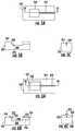
- FIG. 5Ais a top view of an example first stage of an example method for forming an example relative pressure sensor; FIG. 5A illustrating an example substrate for the example relative pressure sensor.
- FIG. 5Bis a sectional view of the example substrate of FIG. 5A taken along line 5 B- 5 B.
- FIG. 5Cis an end view of the example substrate of FIG. 5A .
- FIG. 6Ais a top view of an example second stage of an example method for forming the example relative pressure sensor; FIG. 6A illustrating the example substrate of FIG. 5A following application of an example cover over a channel of the substrate and about a cavity of the substrate.
- FIG. 6Bis a sectional view of the example substrate of FIG. 6A taken along line 6 B- 6 B.
- FIG. 6Cis an end view of the substrate of FIG. 6A .
- FIG. 7Ais a top view of an example pressure sensing die.
- FIG. 7Bis a sectional view of the example pressure sensing die of FIG. 7A .
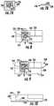
- FIG. 8is a top view of an example third stage of the example method for forming the example relative pressure sensor; FIG. 8 illustrating the example substrate of FIG. 6A after mounting of the pressure sensing die of FIG. 7A .
- FIG. 9is a top view of an example fourth stage of the example method for forming the example relative pressure sensor; FIG. 9 illustrating the example substrate of FIG. 8 following wire bonding and encapsulation.
- FIG. 10is a sectional view of another example substrate for forming a relative pressure sensor.
- FIG. 11is a top view of the example substrate of FIG. 10 .
- FIG. 12is a sectional view of an example relative pressure sensor comprising the example substrate of FIG. 10 after mounting of a pressure sensing die and securement of a cover to the example substrate.
- FIG. 13is an end view of the relative pressure sensor of FIG. 12 .
- FIG. 14is a sectional view of another example relative pressure sensor.
- FIG. 15is a sectional view of an example liquid supply comprising an example sensing unit.
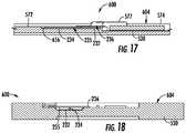
- FIG. 16is a sectional view of another example liquid supply comprising an example sensing unit.
- FIG. 17is a sectional view of the example sensing unit of FIG. 16 taken along line 17 - 17 .
- FIG. 18is a sectional view of the example sensing unit of FIG. 16 taken along line 18 - 18 .
- FIG. 19is a flow diagram of an example method for forming a substrate having a cavity and a channel and positioning a pressure sensing device with respect to the cavity.
- FIG. 20Ais a sectional view of an example first stage of an example method for forming a relative pressure sensor.
- FIG. 20Bis a top view of the example first stage shown in FIG. 20A .
- FIG. 21Ais a sectional view of an example second stage of the example method for forming the relative pressure sensor.
- FIG. 21Bis a top view of the example stage shown in FIG. 21A .
- FIG. 22is a sectional view of an example third stage of the example method for forming the relative pressure sensor.
- FIG. 23Ais a sectional view of an example fourth stage of an example method for forming the relative pressure sensor.
- FIG. 23Bis a top view of the example fourth stage shown in FIG. 23A .
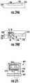
- FIG. 24Ais a sectional view of an example fifth stage of an example method for forming the relative pressure sensor.
- FIG. 24Bis a top view of the example fifth stage shown in FIG. 24A .
- FIG. 25is a front view of a portion of an example sensing unit including the relative pressure sensor.
- FIG. 1illustrates an example relative pressure sensor that is less complex and simpler to manufacture as compared to many currently available relative pressure sensors.
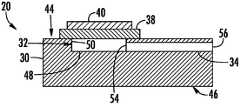
- FIGS. 1-3illustrate an example relative pressure sensor 20 .
- FIG. 1is a top view of the example relative pressure sensor 20 .
- FIG. 2is an end view of the example relative pressure sensor 20 .
- FIG. 3is a sectional view of the example relative pressure sensor FIG. 1 taken along line 3 - 3 .
- Relative pressure sensor 20comprises substrate 30 , cavity 32 , passage 34 , membrane 38 and pressure sensing device 40 .
- Substrate 30comprises a carrier, base or platform for relative pressure sensor 20 .
- Substrate 30has a body in which are formed cavity 32 and passage 34 .
- Cavity 32extends into substrate 30 from a face 44 of substrate 30 .
- Cavity 32has a floor 48 and sidewalls 50 .
- sidewalls 50extend perpendicular to face 44 and perpendicular to the plane containing the major dimensions of membrane 38 and pressure sensing device 40 .
- a “major dimension”refers to the largest dimension, length width or height, of an object.
- substrate 30is molded to form cavity 32 . In another implementation, substrate 30 undergoes a material removal process, such as micro-machining, to form cavity 32 . In one implementation, substrate 30 is formed from a polymer. In one implementation, substrate 30 is formed from a thermoset polymer such as an epoxy molded compound. In one implementation, substrate 30 is formed from, or comprises, a glass, silicon, or other material.
- Passage 34comprises a conduit having a first opening 54 forming a port within cavity 32 and a second opening 56 .
- cavity 32 and the overlying membrane 38 and pressure sensing device 40are located within a first region while port 56 communicates with a second region, wherein pressure sensing device 40 output signals indicating differences in pressures between the first region and the second region.
- passage 34extends along a line that lies in a plane that is parallel to the floor 48 of cavity 32 .
- passage 32may extend to cavity 32 along a line that extends in a plane that is oblique to the floor 48 of cavity 32 .
- passage 34comprises a bore drilled or otherwise formed through the body of substrate 30 , wherein passage 34 is surrounded on all sides by substrate 30 but for opening 54 , 56 .
- passage 34comprises a groove or channel formed in a face of substrate 30 , the channel being bounded by substrate 30 on three sides, wherein a cover is secured to the face of substrate 30 over or opposite to the channel to form the completely bounded or completely surrounded passage 34 .
- Membrane 38comprises a panel of a resiliently flexible material.
- membrane 30comprises a thin silicon membrane.
- Membrane 38is secured to substrate 30 (directly or indirectly) over and across cavity 32 so as to span cavity 32 , beyond opposing sidewalls 50 , opposite to floor 48 .
- Membrane 38supports pressure sensing device 40 .
- Pressure sensing device 40comprises a device that senses flexing of membrane 30 brought about by differences in pressure being exerted upon the exterior side of membrane 38 in the first region and pressure being exerted upon the interior side of membrane 38 , adjacent cavity 32 , and in communication with port 56 via passage 34 .
- pressure sensing device 40comprises a Wheatstone bridge having piezoresistors.
- portions a membrane 38are doped to provide piezoresistors and the electrical traces forming the Wheatstone bridge.
- pressure sensing device 40may comprise other types of pressure sensing devices.
- Membrane 38 and pressure sensing device 40together, form a pressure sensing die, that may be separately formed as a separate unit that is subsequently mounted to substrate 30 .
- FIG. 4is a flow diagram of an example method 100 that may be used to form a relative pressure sensor, such as sensor 20 shown in FIGS. 1-3 .
- the order of the steps illustrated by blocks 104 , 106 and 108is not limited to the order of the illustrated blocks.
- a cavitysuch as cavity 32
- a channelsuch as channel 34
- the channelis formed such that it connects to a cavity, such as cavity 32 , also in substrate 30 .
- the channel that is formedis not enclosed on all sides, but comprises a groove extending into a face of the substrate.
- a pressure sensing devicesuch as pressure sensing device 40
- the pressure sensing deviceis supported by a membrane, wherein the membrane is positioned opposite to the cavity, such as opposite to the floor of the cavity within the substrate.
- block 104precedes block 106 , wherein the pressure sensing device (and membrane) are secured to the substrate after the cavity and the channel have been formed in the substrate.
- block 104proceeds block 106 , wherein the pressure sensing device (and membrane) are supported by a carrier and wherein the substrate is formed on the carrier over the pressure sensing device (and membrane) and over a sacrificial layer which temporary fills and defines the cavity and the channel in the substrate being formed.
- a coveris secured to the substrate opposite the channel to form a passage, such as passage 34 , leading to the cavity.
- the covermay comprise a layer of adhesive, entirely in liquid form, wherein the liquid has a viscosity so as to not completely flow into and fill the channel, but so as to form a ceiling or roof for the channel.
- the covermay comprise a film adhesive, a film, such as a fabric mesh or a solid polymeric panel or layer that is coated with an adhesive for being secured to the substrate.
- the covermay comprise a sheet or panel, which upon being sufficiently stimulated or activated, undergoes changes in its physical state so as to adhere, weld, fuse otherwise bonded to the substrate while extending over and across the channel without completely filling the channel.
- the covermay comprise a panel that is fastened, snapped onto, welded or otherwise secured to substrate 40 over the channel.
- FIGS. 5-9illustrate various stages of one example implementation of method 100 being carried out to form the completed relative pressure sensor 220 (shown in FIG. 9 ).
- a substrate 230is provided in which cavity 232 and channel 233 are formed.
- cavity 232 and channel 233are micro-machined into substrate 230 .
- substrate 230is molded to form cavity 232 and channel 233 are molded.
- substrate 230comprises a polymer, such as a thermosetting polymer, such as an epoxy mold compound.
- substrate 230comprises a glass or silicon material.
- cavity 232comprises a floor 248 and sidewalls 250 .
- Sidewalls 250obliquely extend from face 244 of substrate 230 and are also oblique with respect to floor 248 .
- Sidewalls 250form an acute angle (and angle less than 90°) with respect to the plane of face 244 within cavity 232 .
- Sidewalls 250form an obtuse angle (an angle greater than 90°) with respect to the plane of floor 248 .
- a cover 235is secured to substrate 230 opposite to or over channel 233 to form a completely surrounded passage 234 .
- the covercomprises a deposit of liquid adhesive over channel 233 , wherein the liquid adhesive has a viscosity which inhibits the liquid from completely filling channel 233 , leaving passage 234 .
- the liquid adhesive applied over channel 233is further applied to face 244 of substrate 230 about cavity 232 , wherein the liquid adhesive the subsequent use to secure the pressure sensing device to substrate 230 over cavity 232 , opposite to floor 248 of cavity 232 .
- cover 235may comprise a panel or film coated with an adhesive on opposite faces, wherein the adhesive that is on one face bonds to face 244 of substrate 230 and wherein the adhesive on the other face bonds to a membrane supporting a pressure sensing device.
- the adhesive on either facemay be selectively activated through heat, light, chemical interaction or other catalysts.
- FIGS. 7A and 7Billustrate one example pressure sensing device.
- FIGS. 7A and 7Billustrate an example pressure sensing die 236 which comprises membrane 238 and pressure sensing device 240 .
- Membrane 238is similar to membrane 38 described above.
- Pressure sensing device 240is similar to pressure sensing device 40 described above.
- pressure sensing device 240comprises a Wheatstone bridge having piezoresistors.
- pressure sensing die 236may comprise other types of pressure sensing devices 240 .
- FIG. 8is a top view illustrating the attachment of die 236 to substrate 230 .
- die 236is secured to face 244 of substrate 230 using the adhesive provided as part of cover 235 extending about cavity 232 .
- a separate application of adhesivedistinct from the application of adhesive forming cover 235 , may be employed for securing die 236 to substrate 230 .
- the adhesiveis cured to complete the bonding.
- the adhesiveforms a seal between die 236 and face 244 of substrate 230 .
- FIG. 9is a top view illustrating wire bonding and encapping to complete relative pressure sensor 220 .
- wire bonds or connections 257are made to contact pads 258 of pressure sensing device 240 .
- wire bonds 257 and contact pads 258are encapsulated by an electrically insulating wire encapsulating material 260 such as a polymeric encapsulating epoxy or other material.
- FIGS. 10-13illustrate another example implementation of the method 100 (shown in FIG. 4 ) to form the example completed relative pressure sensor 320 shown in FIGS. 12 and 13 .
- substrate 330is provided in which cavity 332 and channel 333 are formed. While cavity 332 extends into face 344 of substrate 330 , channel 333 extends into face 345 of substrate 330 and communicates with a lower portion of channel 332 at a junction between faces 344 , 345 .
- channel 333may be formed along a side face of substrate 330 , between faces 344 , 345 , and communicating with the interior of cavity 332 at an interior location spaced from each of the faces of substrate 330 .
- cavity 332 and channel 333are micro-machined into substrate 330 .
- substrate 330is molded to form cavity 332 and channel 333 .
- substrate 330comprises a polymer, such as a thermosetting polymer, such as an epoxy mold compound.
- substrate 330comprises a glass or silicon material.
- die 236(described above) is secured to face 344 of substrate 330 opposite to floor 348 of cavity 332 , over and across cavity 332 .
- die 236is secured to face 344 of substrate 330 by an adhesive that extends between membrane 236 and face 344 .
- Cover 335is similar to cover 235 except that cover 335 is secured to face 345 of substrate 330 opposite to channel 333 . Cover 335 covers and spans across channel 333 to form the fully surrounded passage 334 .
- cover 335comprises a deposit of liquid adhesive over channel 333 , wherein the liquid adhesive has a viscosity which inhibits the liquid from completely filling channel 333 , leaving passage 334 .
- cover 335may comprise a panel or film coated with an adhesive on one face that bonds to face 345 of substrate 230 .
- the adhesivemay be selectively activated through heat, light, chemical interaction or other catalysts.
- FIG. 14is a sectional view of relative pressure sensor 420 , another example implementation of relative pressure sensor 20 .
- Relative pressure sensor 420is similar to relative pressure sensor 320 except that cavity 332 is replaced with a cavity 432 that is formed by a passage or opening 451 and cover 435 .
- Opening 451completely extends through substrate 430 from face 444 to face 445 .
- opening 451is spaced from the perimeter or sides of substrate 230 the same as cavity 332 as shown FIG. 11 . Because opening 451 extends completely through substrate 230 , opening 451 may be formed by molding or material removal processes without any depth control.
- Cover 435is similar to cover 335 except that cover 435 additionally spans across and covers a lower end of opening 451 . As with cover 335 , cover 435 is secured to face 445 of substrate 430 opposite to channel 333 so as to form the floor 437 of passage 434 . As shown by FIG. 14 , cover 445 additionally forms the floor 448 of cavity 432 that extends opposite to membrane 238 and pressure sensing device 240 of pressure sensing die 236 .
- cover 435comprises a deposit of liquid adhesive that continuously extends across or over opening 432 , wherein the liquid adhesive has a viscosity which inhibits the liquid from completely filling opening 451 , leaving cavity 432 .
- cover 435may comprise a panel or film coated with an adhesive on one face that bonds to face 445 of substrate 430 . As noted above, in some implementations, the adhesive may be selectively activated through heat, light, chemical interaction or other catalysts.
- FIG. 15is a sectional view of an example liquid supply 500 that includes the relative pressure sensor.
- Liquid supply 500comprises liquid container 502 and sensing unit 504 .
- Container 502receives sensing unit 504 and forms an inner chamber 506 and a fluid interface 508 .
- Chamber 506comprises a volume for receiving or containing a liquid.
- Fluid interface 508comprises a port through which liquid is removed from chamber 506 .
- chamber 506is filled with fluid through port 508 .
- chamber 506is filled through an alternative port.
- fluid interface 508comprises a valve are selectively opening closing support provided by fluid interface 508 .
- Sensing unit 504is mounted to container 502 , partially extending into chamber 506 to sense characteristics of the liquid and contents of chamber 506 .
- sensing unit 504comprises relative pressure sensor 520 , internal pressure sensor 570 , liquid level sensor 572 and electrical interconnect 574 .
- Relative pressure sensor 520may comprise any one of relative pressure sensors 20 , 220 , 320 or 420 described above.
- Relative pressure sensor 520comprises substrate 530 , in which cavity 532 and passage 534 are formed, and pressure sensing die 236 described above. Cavity may comprise any of cavities 32 , 232 , 332 or 432 described above, wherein passage 534 may comprise any of passages 34 , 234 , 334 and 434 described above.
- cavity 532 and pressure sensing die 236are located within chamber 506 where passage 534 extends from cavity 532 across the walls of container 502 to port 556 in communication with the environment or ambient air.
- relative pressure sensor 520senses the relative pressure between the interior of chamber 506 and the exterior of container 502 .
- cavity 532 and pressure sensing die 236may alternatively be supported outside of container 502 , whereas port 506 terminates within chamber 506 .
- Substrate 530is similar to any of the substrate 30 , 230 , 330 or 430 described above except that substrate 530 additionally supports internal pressure sensor 570 , liquid level sensor 572 and electrical interconnect 574 .
- Internal pressure 570is supported within container 506 and senses the absolute pressure within container 506 .
- internal pressure sensor 570comprises a chamber over which a flexible diaphragm supports a pressure sensing device, such as a Wheatstone bridge having piezoresistors.
- Liquid level sensor 572comprises a device projecting into chamber 506 so as to output signals indicating a level of liquid within chamber 506 .
- Electrical interconnect 574comprises electrical contact pads 578 facilitating electrical connection of each of sensors 520 , 570 and 572 to an external controller or computing device. Electrical interconnect 574 is electrically connected to each of sensors 520 , 570 and 572 (and to an acumen controller ASIC chip 573 ) through wire bonding, wherein the wire bonding and the acumen 573 are encapsulated with an encap layer 577 .
- sensors 570 and 572may be supported independent of substrate 530 .
- sensors 570 and 572may comprise other forms of internal pressure sensors and liquid level sensors, respectively.
- electrical interconnect 574may comprise other forms of communication interfaces.
- sensors 570 and 572may be omitted.
- FIG. 16is a sectional view illustrating another example liquid supply 600 .
- Liquid supply 600is similar to liquid supply 500 except the liquid supply 600 includes sensing unit 604 in place of sensing unit 504 .
- FIGS. 17 and 18are sectional views of sensing unit 604 . Those components or elements of liquid supply 600 which correspond to components or elements of liquid supply 500 are numbered similarly.
- Sensing unit 604is similar to sensing unit 504 except that substrate 530 supports cavity 232 and pressure sensing die 236 external to chamber 506 , whereas passage 534 extends through and across the walls of container 502 , terminating at port 656 which is within chamber 506 .
- sensing unit 604is specifically illustrated as comprising relative pressure sensor 230 described above, except that substrate 230 is replaced with substrate 530 .
- Substrate 530is similar to substrate 230 except that substrate 530 additionally supports sensors 570 , 572 and electrical interconnect 574 .
- sensing unit 604may alternatively comprise any of relative pressure sensors 320 and 420 described above.
- sensing unit 600comprises a collar 659 that assists in forming a seal between sensing unit 600 and container 502 .
- FIG. 19is a flow diagram of an example method 700 for forming the cavity and channel of the above described relative pressure sensors 20 , 220 as well as positioning a pressure sensing device relative to the cavity.
- FIGS. 20-25illustrate various stages of an example method for forming the completed relative pressure sensor 220 (shown in FIG. 25 ) pursuant to method 700 .
- FIGS. 20A and 20Billustrate the positioning of pressure sensing die 236 upon a carrier 802 .
- a release mechanism 804such as thermal release tape, is positioned upon carrier 802 between carrier 802 and die 236 .
- a sacrificial layer 806is formed upon carrier 802 , over membrane 238 supporting pressure sensing device 240 .
- the sacrificial layer 806is located and shaped so as to have a negative relief pattern defining the subsequently formed cavity 232 and channel 233 .
- the sacrificial layer 806comprises a layer of lost wax.
- the sacrificial layer 806may comprise other sacrificial materials.
- substrate 230is formed upon or over the sacrificial layer 806 supported by carrier 802 .
- substrate 230comprises a polymer that is moldable.
- substrate 230comprises an epoxy mold compound that upon curing, forms a solid body.
- sacrificial layer 806is removed and the substrate 230 , along with the supported membrane 238 and pressure sensing device 240 , forming die 236 , are separated from carrier 802 .
- sacrificial layer 806comprises lost wax
- the lost waxis melted and drained, developed away by solvent, or otherwise removed.
- the release mechanism 804comprises a thermal release tape
- heatis applied to the tape facilitating such separation.
- removal of the sacrificial layer 806leaves cavity 232 , below pressure sensing die 236 , and channel 233 .
- relative pressure sensor 220may be provided as part of sensor unit 604 described above, wherein the substrate formed pursuant to block 704 further supports other sensors such as pressure sensor 570 and liquid level sensor 572 described above with respect to FIG. 16 .
Landscapes
- Physics & Mathematics (AREA)
- General Physics & Mathematics (AREA)
- Chemical & Material Sciences (AREA)
- Analytical Chemistry (AREA)
- Optics & Photonics (AREA)
- Measuring Fluid Pressure (AREA)
Abstract
Description
Claims (20)
Applications Claiming Priority (3)
| Application Number | Priority Date | Filing Date | Title |
|---|---|---|---|
| PCT/US2015/057728WO2017074334A1 (en) | 2015-10-28 | 2015-10-28 | Relative pressure sensor |
| JP2015242337 | 2015-12-11 | ||
| JP2015-242337 | 2015-12-11 |
Related Parent Applications (1)
| Application Number | Title | Priority Date | Filing Date |
|---|---|---|---|
| PCT/US2015/057728A-371-Of-InternationalWO2017074334A1 (en) | 2015-10-28 | 2015-10-28 | Relative pressure sensor |
Related Child Applications (1)
| Application Number | Title | Priority Date | Filing Date |
|---|---|---|---|
| US16/375,409ContinuationUS20190226930A1 (en) | 2015-10-28 | 2019-04-04 | Relative pressure sensor |
Publications (2)
| Publication Number | Publication Date |
|---|---|
| US20180321100A1 US20180321100A1 (en) | 2018-11-08 |
| US10753815B2true US10753815B2 (en) | 2020-08-25 |
Family
ID=64015224
Family Applications (1)
| Application Number | Title | Priority Date | Filing Date |
|---|---|---|---|
| US15/772,031Expired - Fee RelatedUS10753815B2 (en) | 2015-10-28 | 2015-10-28 | Relative pressure sensor |
Country Status (1)
| Country | Link |
|---|---|
| US (1) | US10753815B2 (en) |
Families Citing this family (2)
| Publication number | Priority date | Publication date | Assignee | Title |
|---|---|---|---|---|
| CN113168446A (en) | 2018-12-03 | 2021-07-23 | 惠普发展公司,有限责任合伙企业 | Logic circuitry packaging |
| US11193842B2 (en)* | 2019-06-06 | 2021-12-07 | Te Connectivity Solutions Gmbh | Pressure sensor assemblies with protective pressure feature of a pressure mitigation element |
Citations (64)
| Publication number | Priority date | Publication date | Assignee | Title |
|---|---|---|---|---|
| US3440873A (en)* | 1967-05-23 | 1969-04-29 | Corning Glass Works | Miniature pressure transducer |
| US4625560A (en)* | 1985-05-13 | 1986-12-02 | The Scott & Fetzer Company | Capacitive digital integrated circuit pressure transducer |
| US4894698A (en)* | 1985-10-21 | 1990-01-16 | Sharp Kabushiki Kaisha | Field effect pressure sensor |
| US5050431A (en) | 1990-09-12 | 1991-09-24 | Robertshaw Controls Company | Liquid level sensing device and methods of making an operating the same |
| JPH05332860A (en) | 1992-05-27 | 1993-12-17 | Canon Inc | Pressure-sensitive sensor and recording device using the same |
| US5335550A (en) | 1992-04-01 | 1994-08-09 | Mitsubishi Denki Kabushiki Kaisha | Semiconductor pressure sensor including multiple silicon substrates bonded together and method of producing the same |
| US5500663A (en) | 1992-02-24 | 1996-03-19 | Canon Kabushiki Kaisha | Recording ink container with an air vent valve |
| US5502467A (en) | 1994-03-07 | 1996-03-26 | Spectra, Inc. | Ink jet printhead with ink viscosity control |
| JPH0886711A (en) | 1994-09-16 | 1996-04-02 | Omron Corp | Pressure sensor device and gas meter using this pressure sensor device |
| JPH08226861A (en) | 1995-02-22 | 1996-09-03 | Omron Corp | Pressure sensor and its mounting structure |
| JPH08247873A (en) | 1995-03-13 | 1996-09-27 | Tokai Rika Co Ltd | Pressure sensor |
| US5581038A (en) | 1994-04-04 | 1996-12-03 | Sentir, Inc. | Pressure measurement apparatus having a reverse mounted transducer and overpressure guard |
| US5583545A (en) | 1994-10-31 | 1996-12-10 | Hewlett-Packard Company | Ink level detection in a pressure regulated pen |
| US6032536A (en) | 1998-09-28 | 2000-03-07 | Xerox Corporation | Pressure sensor and method for detecting pressure |
| US20010037680A1 (en) | 2000-02-22 | 2001-11-08 | Bernd Buck | Capacitive fill level measurment device |
| US20020029639A1 (en)* | 2000-01-19 | 2002-03-14 | Measurement Specialities, Inc. | Isolation technique for pressure sensing structure |
| US6398329B1 (en) | 2000-11-13 | 2002-06-04 | Hewlett-Packard Company | Thermal inkjet pen having a backpressure sensor |
| US6435638B1 (en) | 2000-10-27 | 2002-08-20 | Hewlett-Packard Company | Ink bag fitment with an integrated pressure sensor for low ink detection |
| US6490920B1 (en) | 1997-08-25 | 2002-12-10 | Millennium Sensors Ltd. | Compensated capacitive liquid level sensor |
| US20030056598A1 (en) | 2001-06-19 | 2003-03-27 | Isamu Kimura | Pressure sensor and pressure-measuring apparatus |
| US6554382B1 (en) | 2002-03-19 | 2003-04-29 | Hewlett-Packard Development Company, L.P. | Ink container electrical resistance ink level sensing mechanism and method for determining ink level information |
| US6641240B2 (en) | 2001-02-02 | 2003-11-04 | Benq Corporation | Apparatus for measuring the amount of ink remaining in an ink tank |
| JP2005091166A (en) | 2003-09-17 | 2005-04-07 | Matsushita Electric Works Ltd | Semiconductor pressure sensor |
| US20050241400A1 (en)* | 2004-04-29 | 2005-11-03 | Heinz-Georg Vossenberg | Combined absolute-pressure and relative-pressure sensor |
| US20060066659A1 (en) | 2002-12-19 | 2006-03-30 | Telecom Italia S.P.A. | Process for protectively coating hydraulic microcircuits against agressive liquids, particularly for an ink jet printhead |
| US20060144151A1 (en) | 2002-07-16 | 2006-07-06 | Peter Krause | Pressure transmitter having a pressure sensor of micromechanical design |
| US20070076066A1 (en) | 2005-09-30 | 2007-04-05 | Aldrich Charles S | Ink tank for a printhead |
| US7258005B2 (en) | 2004-02-06 | 2007-08-21 | David Scott Nyce | Isolated capacitive fluid level sensor |
| JP2007276374A (en) | 2006-04-11 | 2007-10-25 | Toppan Printing Co Ltd | Cleaning method for ink jet printing apparatus |
| TW200804781A (en) | 2006-06-05 | 2008-01-16 | Hewlett Packard Development Co | Micro electrical mechanical systems pressure sensor |
| US20080088660A1 (en) | 2006-10-11 | 2008-04-17 | Tommy Otis Lowe | Method for Maintaining Printhead Performance |
| US20080192077A1 (en) | 2005-04-25 | 2008-08-14 | Litrex Corporation | Integral Printhead Assembly |
| US20080231651A1 (en) | 2007-03-21 | 2008-09-25 | Samsung Electronics Co., Ltd. | Ink level detecting apparatus of ink-jet image forming apparatus and method for controlling the same |
| US20090036754A1 (en) | 2007-07-31 | 2009-02-05 | Captomed Eurl | Self-calibrating pressure sensor |
| US7625060B2 (en) | 2002-09-24 | 2009-12-01 | Seiko Epson Corporation | Cartridge, printing apparatus, and method of transmitting information to and from cartridge |
| US7661307B1 (en) | 2007-05-04 | 2010-02-16 | Milone Christopher J | Low manufacturing cost printed ink liquid level sensors |
| US7802471B2 (en) | 2007-12-28 | 2010-09-28 | Sieh Philip J | Liquid level sensing device and method |
| US8075114B2 (en) | 2005-06-01 | 2011-12-13 | Canon Kabushiki Kaisha | Liquid container, liquid supplying system and circuit board for liquid container |
| US20110308324A1 (en) | 2010-06-18 | 2011-12-22 | Sisira Kankanam Gamage | A sensor and method for fabricating the same |
| US20120098898A1 (en) | 2010-10-20 | 2012-04-26 | Xerox Corporation | Method and system for ink delivery and purged ink recovery in an inkjet printer |
| US8373240B2 (en)* | 2009-03-12 | 2013-02-12 | Infineon Technologies Ag | Sensor device having a structure element |
| US8487387B2 (en)* | 2010-08-23 | 2013-07-16 | Freescale Semiconductor, Inc. | MEMS sensor device with multi-stimulus sensing |
| US8522620B2 (en) | 2009-10-16 | 2013-09-03 | Silicon Micro Sensors Gmbh | Pressure sensor and use thereof in a fluid tank |
| US20140015903A1 (en) | 2012-07-13 | 2014-01-16 | Semion Gengrinovich | Ink delivery system |
| US8646860B1 (en) | 2012-07-23 | 2014-02-11 | Xerox Corporation | Piezoelectric sensor arrangement for sensing fluid level in small volume and irregular shape reservoirs |
| US8714933B2 (en) | 2008-01-24 | 2014-05-06 | Ebara Corporation | Water supply apparatus |
| US8740837B2 (en) | 2002-07-19 | 2014-06-03 | Baxter International Inc. | Pumping systems for cassette-based dialysis |
| US20140204148A1 (en) | 2011-06-27 | 2014-07-24 | Ning Ge | Ink level sensor and related methods |
| US8807716B2 (en) | 2008-06-30 | 2014-08-19 | Fujifilm Dimatix, Inc. | Ink delivery |
| US8835191B2 (en)* | 2009-10-26 | 2014-09-16 | International Business Machines Corporation | Nanowire stress sensors and stress sensor integrated circuits, design structures for a stress sensor integrated circuit, and related methods |
| US20140290373A1 (en)* | 2011-08-31 | 2014-10-02 | Robert Bosch Gmbh | Polymer layer system pressure sensor device, and polymer layer system pressure sensor method |
| CN104310299A (en) | 2013-02-22 | 2015-01-28 | 大陆汽车系统公司 | Cap bonding structure and method for backside absolute pressure sensors |
| DE102014207480A1 (en) | 2014-04-17 | 2015-10-22 | Robert Bosch Gmbh | Device for detecting a parameter of a gas, method for operating such a device and measuring system for determining a parameter of a gas |
| US9261395B2 (en) | 2012-02-13 | 2016-02-16 | Goodrich Corporation | Liquid level sensing system |
| US20160061677A1 (en)* | 2014-09-02 | 2016-03-03 | Apple Inc. | Various stress free sensor packages using wafer level supporting die and air gap technique |
| US9358798B2 (en) | 2011-08-30 | 2016-06-07 | Brother Kogyo Kabushiki Kaisha | Printing fluid cartridge, printing apparatus, and use of printing fluid cartridge |
| US9488513B2 (en) | 2012-12-05 | 2016-11-08 | Molex, Llc | Flexible fluid level sensor with improved measurement capability |
| US20160370242A1 (en)* | 2015-06-22 | 2016-12-22 | Stmicroelectronics S.R.L. | Pressure sensor generating a transduced signal with reduced ambient temperature dependence, and manufacturing method thereof |
| US20170284882A1 (en)* | 2016-03-31 | 2017-10-05 | Stmicroelectronics S.R.L. | Process for manufacturing a mems pressure sensor, and corresponding mems pressure sensor |
| US20170340147A1 (en) | 2015-03-09 | 2017-11-30 | Hidrate, Inc. | Wireless drink container for monitoring hydration |
| US20180038754A1 (en)* | 2016-08-05 | 2018-02-08 | Encite Llc | Micro Pressure Sensor |
| US9962949B2 (en) | 2014-01-30 | 2018-05-08 | Hewlett-Packard Development Company, L.P. | Printheads with sensor plate impedance measurement |
| US10124597B2 (en) | 2016-05-09 | 2018-11-13 | R.R. Donnelley & Sons Company | System and method for supplying ink to an inkjet printhead |
| US10220630B2 (en) | 2011-08-30 | 2019-03-05 | Brother Kogyo Kabushiki Kaisha | Printing fluid cartridge, printing apparatus, and use of printing fluid cartridge |
- 2015
- 2015-10-28USUS15/772,031patent/US10753815B2/ennot_activeExpired - Fee Related
Patent Citations (71)
| Publication number | Priority date | Publication date | Assignee | Title |
|---|---|---|---|---|
| US3440873A (en)* | 1967-05-23 | 1969-04-29 | Corning Glass Works | Miniature pressure transducer |
| US4625560A (en)* | 1985-05-13 | 1986-12-02 | The Scott & Fetzer Company | Capacitive digital integrated circuit pressure transducer |
| US4894698A (en)* | 1985-10-21 | 1990-01-16 | Sharp Kabushiki Kaisha | Field effect pressure sensor |
| US5050431A (en) | 1990-09-12 | 1991-09-24 | Robertshaw Controls Company | Liquid level sensing device and methods of making an operating the same |
| US5500663A (en) | 1992-02-24 | 1996-03-19 | Canon Kabushiki Kaisha | Recording ink container with an air vent valve |
| US5335550A (en) | 1992-04-01 | 1994-08-09 | Mitsubishi Denki Kabushiki Kaisha | Semiconductor pressure sensor including multiple silicon substrates bonded together and method of producing the same |
| JPH05332860A (en) | 1992-05-27 | 1993-12-17 | Canon Inc | Pressure-sensitive sensor and recording device using the same |
| US5502467A (en) | 1994-03-07 | 1996-03-26 | Spectra, Inc. | Ink jet printhead with ink viscosity control |
| US5581038A (en) | 1994-04-04 | 1996-12-03 | Sentir, Inc. | Pressure measurement apparatus having a reverse mounted transducer and overpressure guard |
| JPH0886711A (en) | 1994-09-16 | 1996-04-02 | Omron Corp | Pressure sensor device and gas meter using this pressure sensor device |
| US5583545A (en) | 1994-10-31 | 1996-12-10 | Hewlett-Packard Company | Ink level detection in a pressure regulated pen |
| JPH08226861A (en) | 1995-02-22 | 1996-09-03 | Omron Corp | Pressure sensor and its mounting structure |
| JPH08247873A (en) | 1995-03-13 | 1996-09-27 | Tokai Rika Co Ltd | Pressure sensor |
| US6490920B1 (en) | 1997-08-25 | 2002-12-10 | Millennium Sensors Ltd. | Compensated capacitive liquid level sensor |
| US6032536A (en) | 1998-09-28 | 2000-03-07 | Xerox Corporation | Pressure sensor and method for detecting pressure |
| US20020029639A1 (en)* | 2000-01-19 | 2002-03-14 | Measurement Specialities, Inc. | Isolation technique for pressure sensing structure |
| US20010037680A1 (en) | 2000-02-22 | 2001-11-08 | Bernd Buck | Capacitive fill level measurment device |
| US6435638B1 (en) | 2000-10-27 | 2002-08-20 | Hewlett-Packard Company | Ink bag fitment with an integrated pressure sensor for low ink detection |
| US6398329B1 (en) | 2000-11-13 | 2002-06-04 | Hewlett-Packard Company | Thermal inkjet pen having a backpressure sensor |
| US6641240B2 (en) | 2001-02-02 | 2003-11-04 | Benq Corporation | Apparatus for measuring the amount of ink remaining in an ink tank |
| US20030056598A1 (en) | 2001-06-19 | 2003-03-27 | Isamu Kimura | Pressure sensor and pressure-measuring apparatus |
| US6554382B1 (en) | 2002-03-19 | 2003-04-29 | Hewlett-Packard Development Company, L.P. | Ink container electrical resistance ink level sensing mechanism and method for determining ink level information |
| US20060144151A1 (en) | 2002-07-16 | 2006-07-06 | Peter Krause | Pressure transmitter having a pressure sensor of micromechanical design |
| US8740837B2 (en) | 2002-07-19 | 2014-06-03 | Baxter International Inc. | Pumping systems for cassette-based dialysis |
| US7625060B2 (en) | 2002-09-24 | 2009-12-01 | Seiko Epson Corporation | Cartridge, printing apparatus, and method of transmitting information to and from cartridge |
| US20080099341A1 (en) | 2002-12-19 | 2008-05-01 | Telecom Italia S.P.A. | Process for protectively coating hydraulic microcircuits against aggressive liquids, particulary for an ink jet printhead |
| US20060066659A1 (en) | 2002-12-19 | 2006-03-30 | Telecom Italia S.P.A. | Process for protectively coating hydraulic microcircuits against agressive liquids, particularly for an ink jet printhead |
| JP2005091166A (en) | 2003-09-17 | 2005-04-07 | Matsushita Electric Works Ltd | Semiconductor pressure sensor |
| US7258005B2 (en) | 2004-02-06 | 2007-08-21 | David Scott Nyce | Isolated capacitive fluid level sensor |
| US20050241400A1 (en)* | 2004-04-29 | 2005-11-03 | Heinz-Georg Vossenberg | Combined absolute-pressure and relative-pressure sensor |
| US20080192077A1 (en) | 2005-04-25 | 2008-08-14 | Litrex Corporation | Integral Printhead Assembly |
| US8740361B2 (en) | 2005-06-01 | 2014-06-03 | Canon Kabushiki Kaisha | Liquid container, liquid supplying system and circuit board for liquid container |
| US8075114B2 (en) | 2005-06-01 | 2011-12-13 | Canon Kabushiki Kaisha | Liquid container, liquid supplying system and circuit board for liquid container |
| US20070076066A1 (en) | 2005-09-30 | 2007-04-05 | Aldrich Charles S | Ink tank for a printhead |
| US7399074B2 (en) | 2005-09-30 | 2008-07-15 | Lexmark International, Inc. | Ink tank for a printhead |
| JP2007276374A (en) | 2006-04-11 | 2007-10-25 | Toppan Printing Co Ltd | Cleaning method for ink jet printing apparatus |
| TW200804781A (en) | 2006-06-05 | 2008-01-16 | Hewlett Packard Development Co | Micro electrical mechanical systems pressure sensor |
| US20080088660A1 (en) | 2006-10-11 | 2008-04-17 | Tommy Otis Lowe | Method for Maintaining Printhead Performance |
| US20080231651A1 (en) | 2007-03-21 | 2008-09-25 | Samsung Electronics Co., Ltd. | Ink level detecting apparatus of ink-jet image forming apparatus and method for controlling the same |
| US7661307B1 (en) | 2007-05-04 | 2010-02-16 | Milone Christopher J | Low manufacturing cost printed ink liquid level sensors |
| US20090036754A1 (en) | 2007-07-31 | 2009-02-05 | Captomed Eurl | Self-calibrating pressure sensor |
| US7802471B2 (en) | 2007-12-28 | 2010-09-28 | Sieh Philip J | Liquid level sensing device and method |
| US8714933B2 (en) | 2008-01-24 | 2014-05-06 | Ebara Corporation | Water supply apparatus |
| US8807716B2 (en) | 2008-06-30 | 2014-08-19 | Fujifilm Dimatix, Inc. | Ink delivery |
| US8373240B2 (en)* | 2009-03-12 | 2013-02-12 | Infineon Technologies Ag | Sensor device having a structure element |
| US8522620B2 (en) | 2009-10-16 | 2013-09-03 | Silicon Micro Sensors Gmbh | Pressure sensor and use thereof in a fluid tank |
| US8835191B2 (en)* | 2009-10-26 | 2014-09-16 | International Business Machines Corporation | Nanowire stress sensors and stress sensor integrated circuits, design structures for a stress sensor integrated circuit, and related methods |
| US20110308324A1 (en) | 2010-06-18 | 2011-12-22 | Sisira Kankanam Gamage | A sensor and method for fabricating the same |
| US8487387B2 (en)* | 2010-08-23 | 2013-07-16 | Freescale Semiconductor, Inc. | MEMS sensor device with multi-stimulus sensing |
| US20120098898A1 (en) | 2010-10-20 | 2012-04-26 | Xerox Corporation | Method and system for ink delivery and purged ink recovery in an inkjet printer |
| US20140204148A1 (en) | 2011-06-27 | 2014-07-24 | Ning Ge | Ink level sensor and related methods |
| US10082414B2 (en) | 2011-06-27 | 2018-09-25 | Hewlett-Packard Development Company, L.P. | Ink level sensing |
| US9358798B2 (en) | 2011-08-30 | 2016-06-07 | Brother Kogyo Kabushiki Kaisha | Printing fluid cartridge, printing apparatus, and use of printing fluid cartridge |
| US10220630B2 (en) | 2011-08-30 | 2019-03-05 | Brother Kogyo Kabushiki Kaisha | Printing fluid cartridge, printing apparatus, and use of printing fluid cartridge |
| US9766144B2 (en)* | 2011-08-31 | 2017-09-19 | Robert Bosch Gmbh | Polymer layer system pressure sensor device, and polymer layer system pressure sensor method |
| US20140290373A1 (en)* | 2011-08-31 | 2014-10-02 | Robert Bosch Gmbh | Polymer layer system pressure sensor device, and polymer layer system pressure sensor method |
| US9261395B2 (en) | 2012-02-13 | 2016-02-16 | Goodrich Corporation | Liquid level sensing system |
| US20140015903A1 (en) | 2012-07-13 | 2014-01-16 | Semion Gengrinovich | Ink delivery system |
| US9573377B2 (en) | 2012-07-13 | 2017-02-21 | Hewlett-Packard Industrial Printing Ltd. | Ink delivery system |
| US8646860B1 (en) | 2012-07-23 | 2014-02-11 | Xerox Corporation | Piezoelectric sensor arrangement for sensing fluid level in small volume and irregular shape reservoirs |
| US9488513B2 (en) | 2012-12-05 | 2016-11-08 | Molex, Llc | Flexible fluid level sensor with improved measurement capability |
| CN104310299A (en) | 2013-02-22 | 2015-01-28 | 大陆汽车系统公司 | Cap bonding structure and method for backside absolute pressure sensors |
| US10336089B2 (en) | 2014-01-30 | 2019-07-02 | Hewlett-Packard Development Company, L.P. | Printheads with sensor plate impedance measurement |
| US9962949B2 (en) | 2014-01-30 | 2018-05-08 | Hewlett-Packard Development Company, L.P. | Printheads with sensor plate impedance measurement |
| DE102014207480A1 (en) | 2014-04-17 | 2015-10-22 | Robert Bosch Gmbh | Device for detecting a parameter of a gas, method for operating such a device and measuring system for determining a parameter of a gas |
| US20160061677A1 (en)* | 2014-09-02 | 2016-03-03 | Apple Inc. | Various stress free sensor packages using wafer level supporting die and air gap technique |
| US20170340147A1 (en) | 2015-03-09 | 2017-11-30 | Hidrate, Inc. | Wireless drink container for monitoring hydration |
| US20160370242A1 (en)* | 2015-06-22 | 2016-12-22 | Stmicroelectronics S.R.L. | Pressure sensor generating a transduced signal with reduced ambient temperature dependence, and manufacturing method thereof |
| US20170284882A1 (en)* | 2016-03-31 | 2017-10-05 | Stmicroelectronics S.R.L. | Process for manufacturing a mems pressure sensor, and corresponding mems pressure sensor |
| US10124597B2 (en) | 2016-05-09 | 2018-11-13 | R.R. Donnelley & Sons Company | System and method for supplying ink to an inkjet printhead |
| US20180038754A1 (en)* | 2016-08-05 | 2018-02-08 | Encite Llc | Micro Pressure Sensor |
Non-Patent Citations (2)
| Title |
|---|
| Extended European Search Report for EP15907441 dated May 7, 2019. |
| Ink flow, Mar. 10, 2011, <http://www.riso.ro/CC/ComColor%20Queries/ComColor_Tips_Ver6.0/Contents/category/. |
Also Published As
| Publication number | Publication date |
|---|---|
| US20180321100A1 (en) | 2018-11-08 |
Similar Documents
| Publication | Publication Date | Title |
|---|---|---|
| US20190226930A1 (en) | Relative pressure sensor | |
| US7911315B2 (en) | Miniature pressure sensor assembly for catheter | |
| CN102659069B (en) | Part and its manufacture method with least one MEMS component | |
| CN102381678B (en) | MEMS device assembly and method for packing thereof | |
| CN106946214A (en) | MEMS sensor and its manufacture method with lateral port | |
| US11355423B2 (en) | Bottom package exposed die MEMS pressure sensor integrated circuit package design | |
| CN107615034A (en) | Device for sensing the pressure of a fluid medium and method for manufacturing the same | |
| US9598280B2 (en) | Environmental sensor structure | |
| CN102365540A (en) | Exposed pad backside pressure sensor package | |
| CN104249990A (en) | MEMS device incorporating fluidic path, and manufacturing process thereof | |
| EP2871152B1 (en) | Sensor device | |
| US10753815B2 (en) | Relative pressure sensor | |
| KR20120135104A (en) | Dual port pressure sensor | |
| CN104236628A (en) | Four-degree-of-freedom combined sensor | |
| US9510495B2 (en) | Electronic devices with cavity-type, permeable material filled packages, and methods of their manufacture | |
| WO2024006346A1 (en) | Sensor package having a channel integrated within a substrate | |
| CN104409428A (en) | Integrated sensor and packaging method thereof | |
| US9476788B2 (en) | Semiconductor sensor with gel filled cavity | |
| US11600559B2 (en) | Sensor device and method of manufacture | |
| US20090145237A1 (en) | Sensor packaging method for a human contact interface | |
| CN114136533A (en) | Packaging structure and packaging method of a pressure sensor | |
| TWI583618B (en) | Micromechanical system and method of manufacturing micromechanical system | |
| US10994989B2 (en) | Method for producing a microelectromechanical component and wafer system | |
| JP6266351B2 (en) | Sensor device and manufacturing method thereof | |
| US20250085182A1 (en) | Low stress packaging for environmental sensors |
Legal Events
| Date | Code | Title | Description |
|---|---|---|---|
| AS | Assignment | Owner name:HEWLETT-PACKARD DEVELOPMENT COMPANY, L.P., TEXAS Free format text:ASSIGNMENT OF ASSIGNORS INTEREST;ASSIGNORS:CUMBIE, MICHAEL W.;CHEN, CHIEN-HUA;REEL/FRAME:045662/0502 Effective date:20151026 | |
| FEPP | Fee payment procedure | Free format text:ENTITY STATUS SET TO UNDISCOUNTED (ORIGINAL EVENT CODE: BIG.); ENTITY STATUS OF PATENT OWNER: LARGE ENTITY | |
| STPP | Information on status: patent application and granting procedure in general | Free format text:APPLICATION DISPATCHED FROM PREEXAM, NOT YET DOCKETED | |
| STPP | Information on status: patent application and granting procedure in general | Free format text:DOCKETED NEW CASE - READY FOR EXAMINATION | |
| STPP | Information on status: patent application and granting procedure in general | Free format text:NON FINAL ACTION MAILED | |
| STPP | Information on status: patent application and granting procedure in general | Free format text:RESPONSE TO NON-FINAL OFFICE ACTION ENTERED AND FORWARDED TO EXAMINER | |
| STPP | Information on status: patent application and granting procedure in general | Free format text:DOCKETED NEW CASE - READY FOR EXAMINATION | |
| STPP | Information on status: patent application and granting procedure in general | Free format text:PUBLICATIONS -- ISSUE FEE PAYMENT VERIFIED | |
| STCF | Information on status: patent grant | Free format text:PATENTED CASE | |
| FEPP | Fee payment procedure | Free format text:MAINTENANCE FEE REMINDER MAILED (ORIGINAL EVENT CODE: REM.); ENTITY STATUS OF PATENT OWNER: LARGE ENTITY | |
| LAPS | Lapse for failure to pay maintenance fees | Free format text:PATENT EXPIRED FOR FAILURE TO PAY MAINTENANCE FEES (ORIGINAL EVENT CODE: EXP.); ENTITY STATUS OF PATENT OWNER: LARGE ENTITY | |
| STCH | Information on status: patent discontinuation | Free format text:PATENT EXPIRED DUE TO NONPAYMENT OF MAINTENANCE FEES UNDER 37 CFR 1.362 | |
| FP | Lapsed due to failure to pay maintenance fee | Effective date:20240825 |