US10753198B2 - Downhole instrument for deep formation imaging deployed within a drill string - Google Patents
Downhole instrument for deep formation imaging deployed within a drill stringDownload PDFInfo
- Publication number
- US10753198B2 US10753198B2US15/097,724US201615097724AUS10753198B2US 10753198 B2US10753198 B2US 10753198B2US 201615097724 AUS201615097724 AUS 201615097724AUS 10753198 B2US10753198 B2US 10753198B2
- Authority
- US
- United States
- Prior art keywords
- drill string
- instrument
- formation
- drilling
- signal
- Prior art date
- Legal status (The legal status is an assumption and is not a legal conclusion. Google has not performed a legal analysis and makes no representation as to the accuracy of the status listed.)
- Expired - Fee Related, expires
Links
Images


Classifications
- E—FIXED CONSTRUCTIONS
- E21—EARTH OR ROCK DRILLING; MINING
- E21B—EARTH OR ROCK DRILLING; OBTAINING OIL, GAS, WATER, SOLUBLE OR MELTABLE MATERIALS OR A SLURRY OF MINERALS FROM WELLS
- E21B49/00—Testing the nature of borehole walls; Formation testing; Methods or apparatus for obtaining samples of soil or well fluids, specially adapted to earth drilling or wells
- E—FIXED CONSTRUCTIONS
- E21—EARTH OR ROCK DRILLING; MINING
- E21B—EARTH OR ROCK DRILLING; OBTAINING OIL, GAS, WATER, SOLUBLE OR MELTABLE MATERIALS OR A SLURRY OF MINERALS FROM WELLS
- E21B33/00—Sealing or packing boreholes or wells
- E21B33/02—Surface sealing or packing
- E21B33/03—Well heads; Setting-up thereof
- E21B33/068—Well heads; Setting-up thereof having provision for introducing objects or fluids into, or removing objects from, wells
- E21B33/072—Well heads; Setting-up thereof having provision for introducing objects or fluids into, or removing objects from, wells for cable-operated tools
- E—FIXED CONSTRUCTIONS
- E21—EARTH OR ROCK DRILLING; MINING
- E21B—EARTH OR ROCK DRILLING; OBTAINING OIL, GAS, WATER, SOLUBLE OR MELTABLE MATERIALS OR A SLURRY OF MINERALS FROM WELLS
- E21B47/00—Survey of boreholes or wells
- E21B47/12—Means for transmitting measuring-signals or control signals from the well to the surface, or from the surface to the well, e.g. for logging while drilling
Definitions
- informationis sometimes transmitted to the surface from instruments within the wellbore, and/or from the surface to downhole instruments.
- signalsmay be transmitted to or from measuring-while-drilling (MWD) equipment, logging-while-drilling (LWD) equipment, steering equipment, or other equipment.
- MWDmeasuring-while-drilling
- LWDlogging-while-drilling
- Such informationmay assist operators in the task of efficiently drilling a wellbore by providing information related to tool-face orientation and formation composition, and allowing commands and configuring of the downhole instruments, among other possible uses.
- information about the subterranean formationmay be acquired using sensors deployed into the wellbore for deep-imaging of the sub-terrain.
- seismic datamay be acquired using geophones, enabling the generation of vertical seismic profiles, and other types of seismic images, to be generated, which may provide insight into the structure, lithology, etc. of the formation.
- a seismic sourcegenerally a vibrator, is then used to generate seismic waves that propagate though the formation and are detected by the seismic sensors such as geophones, accelerometers or geophones.
- the seismic sensormay cover an adequate extent of the wellbore.
- the seismic sensorsmay be moved within the wellbore, while the surface seismic source may be stationary. This type of seismic technique is generally not done simultaneously with drilling operations, but may be done when the drill string is removed, using wireline logging methods associated with surface seismic source.
- Another deep-imaging techniquemay be based on electromagnetic systems.
- an electromagnetic signalis passed through the formation and detected by a receiver.
- the characteristics of the signalmay provide information about the formation within about 50 feet (about 15 m) of the wellbore.
- cross-well tomographycan be performed by electromagnetic system.
- the source and the receivermay be moved to multiple positions to for additional illumination paths. This type of electromagnetic tomography is generally not done simultaneously with drilling operations, but may be done when the drill string is removed, using wireline logging method in one well while the source may be located at the surface or in another well.
- Embodiments of the disclosuremay provide a method for acquiring data in a wellbore.
- the methodincludes deploying an instrument connected to an instrument line into a drill string, through a sealed entry port formed in a drilling device coupled to the drill string, the drill string being at least partially within the wellbore, the wellbore penetrating a subterranean formation.
- the methodalso includes transmitting a signal from a source and through the formation. The signal is sensed by the instrument in the drill string.
- the methodfurther includes determining one or more formation characteristics based on the signal sensed by the instrument, and performing one or more drilling processes using the drill string, while transmitting the signal, determining the one or more formation characteristics, or both.
- Embodiments of the disclosuremay also provide a system for acquiring data in a wellbore.
- the systemincludes a drilling device including an entry port.
- the systemalso includes a sealing device coupled to the drilling device and configured to seal the entry port, a drill string in communication with the entry port and at least partially positioned within a wellbore that penetrates a subterranean formation, and an instrument line received through the entry port and through an interior of at least a portion of the drill string.
- the sealing deviceis configured to seal with the instrument line, while allowing the instrument line to move with respect thereto.
- the systemfurther includes an instrument coupled to the instrument line and positioned within the drill string, the instrument including at least one of a seismic sensor and a voltage sensor.
- FIG. 1illustrates a side, schematic view of a drill string logging tool deployed as part of a drilling rig, according to an embodiment.
- FIG. 2illustrates a side, schematic view of another drill string logging tool, also deployed as part of a drilling rig, according to an embodiment.
- FIG. 3illustrates a side, schematic view of a system for deploying the drill string logging tool within the drill string during drilling operations, according to an embodiment.
- FIG. 4illustrates a flowchart of a method for acquiring data within a drill string, according to an embodiment.
- FIG. 5illustrates a schematic view of a computing system, according to an embodiment.
- first, second, etc.may be used herein to describe various elements, these elements should not be limited by these terms. These terms are only used to distinguish one element from another. For example, a first object could be termed a second object or step, and, similarly, a second object could be termed a first object or step, without departing from the scope of the present disclosure.
- FIG. 1illustrates a schematic view of a drilling rig 100 , according to an embodiment.
- the drilling rig 100may provide a system by which data may be acquired within a wellbore 106 , in addition to drilling the wellbore 106 .
- the drilling rig 100includes a drilling apparatus 102 and a drill string 104 coupled thereto.
- the drilling apparatus 102may include any type of drilling device, such as a top drive or any other device configured to support, lower, and rotate the drill string 104 , which may be deployed into a wellbore 106 extending through a subterranean formation 107 .
- the drilling apparatus 102may also include a travelling block 105 , which may include one or more rotating sheaves.
- the drill string 104may include a bottom-hole assembly 109 , which may include a drill bit, mud motor, LWD and/or MWD equipment, or other equipment.
- the drilling rig 100may also include a rig floor 108 , from which a support structure (e.g., including a mast) 110 may extend.
- a slips assembly 111may be disposed at the rig floor 108 , and may be configured to engage the drill string 104 so as to enable a new stand of tubulars to be added to the drill string 104 via the drilling apparatus 102 .
- a crown block 112may be coupled to the support structure 110 . Further, a drawworks 114 may be coupled to the rig floor 108 . A drill line 116 may extend between the drawworks 114 and the crown block 112 , and may be received through the sheaves of the travelling block 105 . Accordingly, the position of the drilling apparatus 102 may be changed (e.g., raised or lowered) by spooling or unspooling the drilling line 116 from the drawworks 114 , e.g., by rotation of the drawworks 114 . The drilling apparatus 102 may rotate the drill string 104 as part of the drilling operation, e.g., to rotate a drill bit of a bottom-hole assembly at the distal end of the drill string 104 .
- the drilling rig 100may also include an instrument line 120 , which may be received through the drilling apparatus 102 and into the drill string 104 .
- the instrument line 120may be spooled on an instrument line spool 122 , and may be received at least partially around a line sheave 124 between the instrument line spool 122 and the drilling apparatus 102 .
- the instrument line spool 122may be coupled to the rig floor 108 as shown, but in other embodiments, maybe positioned anywhere on the rig 100 , e.g., at or below the crown block 112 , or in proximity, but off of, the rig 100 .
- the sheave 124may be installed above the crown-block 112 , below the crown-block 112 , or on the side of the crown block 112 . In some embodiments, the sheave 124 may be attached to the travelling block 105 .
- the instrument line 120may be connected to one or more downhole instruments, such as one or more drill string logging tools (two shown: 126 , 127 ), which may be deployed into the interior of the drill string 104 , as will be described in greater detail below.
- the position of the drill string logging tools 126 , 127may be changed (e.g., raised or lowered) by spooling or unspooling the instrument line 120 from the instrument line spool 122 .
- the drill string logging toolsmay be geophones, hydrophones, or other types of seismic sensors.
- the instrument line 120may provide for wired communication with a controller 128 , e.g., without calling for wires to be formed as a part of the drill pipe making up the drill string 104 .
- a seismic source 150such as a seismic vibrator, as shown, may be employed to generate seismic waves within the formation 107 , as schematically illustrated by waves 152 .
- the source 150may transmit a frequency sweep of a signal into the formation 107 .
- the seismic source 150may generate an impulse, using either explosive or air gun.
- the seismic source 150may be positioned a horizontal distance from the wellbore 106 , referred to as an offset.
- the waves 152are depicted, for purposes of illustration herein, by rays 154 , 155 , 156 , 157 , 158 , 159 (i.e., rays 154 - 159 ). It will be appreciated that potentially an infinite number of rays may be drawn, with those shown merely being employed for the purposes of illustrating aspects of the present disclosure.
- the rays 154 - 159may propagate through the formation 107 and at least some may be reflected by reflectors, generally at interfaces 160 , 162 between two different types of rock, while some seismic energy propagates across the interface according to Snell's law defining diffraction.
- the interfaces 160 , 162may represent the boundaries for a reservoir 164 or another layer, compartment, or region of interest in the formation 107 .
- reflection and refraction eventsmay also exist in the overburden (i.e., the rock in the formation 107 above the reservoir 164 ). Information about such events in the overburden may also be collected.
- the rays 154 - 159 (reflected or direct arrivals) of the seismic waves 152may be sensed by the drill string logging tools 126 , 127 .
- the data acquired by the drill string logging tools 126 , 127may be transmitted to the controller 128 (or another processor) for processing.
- the controller 128may consider the depth of the tools 126 , 127 , that is, the distance from the top surface. The depth may be based on the length of the instrument line 120 , which may be determined based on the rotation of the instrument line spool 122 .
- the controller 128may also consider the offset of the seismic source 150 , and knowledge gained during drilling about the formation at or near the wellbore 106 . One, some, or each of these factors, and/or others, may then be employed to invert the seismic data acquired by the tools 126 , 127 into information about the characteristics of the formation 107 .
- the seismic source 150may be moved on surface to change the offset. This may directly affect the paths of the seismic rays 154 - 159 , allowing imaging of the formation 107 at different offsets and ray paths (inclination of the rays). Furthermore, the logging tools 126 , 127 may be moved in the drill string 104 allowing different rays to be received, for wider coverage of the image. With these two movements (at the source 150 and the receivers 126 , 127 ), greater (e.g., full) seismic coverage can be achieved across the formation 107 .
- the transmitted seismic signal form the source 150may be configured to promote a high signal-to-nose ratio (SNR) at reception.
- the surface source 150can be fired when the drilling activity is suspended so that the seismic sensor in the logging tools are not affected by noise due to drilling, such as friction with the well bore, vibrations, shock with the well bore, and flow noise.
- the source 150may be operated while some drilling activities are occurring, and in such case, the vibrator may send long and complex sweep of seismic signals into the formation 107 , so that the SNR at reception after cross-correlation with transmitted signal is sufficient for proper seismic imaging purpose.
- the transmitted signal from the vibrator 150can extend over more than 30 seconds and even be up to several minutes (two or more). Also multiples transmission of signal can be performed with a total time for transmission being less than six minutes for one point of imaging process.
- the downhole data acquisitionmay be synchronized with the clock controlling the seismic source.
- the clock in the logging instruments 126 , 127may be synchronized with the clock of the surface controller 128 . This may be achieved by sending a synchronization signal along the instrument line 120 .
- FIG. 2illustrates a side, schematic view of the drilling rig 100 , showing another type of drill string logging tool 200 deployed in the drill string 104 , according to an embodiment.
- the drill string logging tool 200may configured to detect electrical current propagation in the formation 107 .
- the currentmay be generated by either a surface source or a downhole source.
- the sourcemay be a dipole either installed at the surface or downhole.
- the sourcemay include electrodes connected at the surface such as electrodes 202 or via the drill string 104 .
- the drill string 104may act as an electrode (as shown in FIG. 2 ) via grounding of the casing already in the well, as there is contact between the casing and drill sting 104 .
- a difference of potentialmay be generated between the two electrodes via the cable 203 or a current can be injected in cable 203 between the two electrodes.
- the downhole sourcemay include the electrical gap 206 as used for e-mag MWD telemetry. This gap 206 may be an electrical insulator along the drill string 104 .
- the current flowing in the formation 107returns to the source via the metallic tubulars in the well such as the drill string 104 and/or the casing string.
- the detectionmay be performed by spreading electrodes, allowing measurement of a voltage differential along the drill string 104 (or the casing, or another well tubular or structure).
- the detectionmay also be conducted using one or more antennas surrounding the metallic tubular (e.g., the drill string 104 ), or using magnetometers in the vicinity of the metallic structure (e.g., the drill string 104 ).
- the surface electrode 202may be offset from the wellbore 106 by a distance.
- the surface electrode 202may be connected with a source of current, such as alternating current, e.g., via the cable 203 .
- the currentmay travel from the surface electrode 202 and through the formation 107 .
- the bottom-hole assembly 109may include an electromagnetic (“e-mag”) signal generator 204 .
- the gap 206may be employed with the signal generator 204 .
- the surface dipolemay be used either as transmitter or receiver.
- the downhole dipole(e.g., including the gap 206 ) may also be used as transmitter or receiver.
- the first electrical circuit, represented by current lines 208may be a “downlink,” which may carry current from the surface electrode 202 to the drill string 104 via the formation 107 .
- the first electrical circuitrepresented by current lines 208 may be a “downlink,” which may carry current from the surface electrode 202 to the drill string 104 via the formation 107 .
- at least some of the current injected via the surface electrodemay follow a path 208 through the formation 107 to the bottom-hole assembly 109 .
- This currentmay then pass through the bottom-hole assembly 109 , through the drill string 104 (and/or the casing or another conductive structure), back to the top surface and through the current-injection line 203 .
- Other portions of the currenttravel through the formation 107 to the drill string 104 via other paths 208 .
- the drill string logging tool 200may measure the voltage differential along the drill string 104 . From this measurement, the current density of the signal in the drill string 104 may be determined. For example, this measurement may be taken at multiple depths in the drill string 104 . As the voltage differential changes according to depth, inferences about the existence of resistivity boundaries in the formation 107 may be made. For example, if a resistivity boundary 209 exists in the formation 107 , the current density in the drill string 104 below a certain depth may be expected to be lower than the current density in the drill string 104 above the corresponding depth, as the current received in the drill string 104 travels upwards through the drill string 104 . Accordingly, based on the voltage differential measured by the tool 200 , tomographic information about the formation 107 between the drill string 104 and the surface electrode 202 may be inferred.
- the second electrical circuitmay extend from the e-mag signal generator 204 , through the formation 107 via paths 210 to the bottom-hole assembly 109 on the other side of the gap 206 , and back through the drill string 104 to the e-mag signal generator 204 .
- the resistivity of the formation 107which may vary, may affect the current density of the current within the drill string 104 .
- the current densitymay be determined based on a voltage differential measured by the drill string logging tool 200 . For example, if the resistivity boundary 209 exists at a particular depth, current in the drill string 104 above a corresponding depth may be expected to be attenuated, while current in the drill string 104 below the corresponding depth may be expected to be greater.
- the receiver in the logging tool 200may be moved in multiple positions along the drill string 104 via the instrument line 120 and the spool 122 , while signals are transmitted from either the surface electrodes 202 or the downhole signal generator 206 .
- Multiple surface electrodes 202may be used to insure several injection points at surface, or a single electrode 202 may be moved.
- the downhole dipole 206may be moved, as well, and this may occur during drilling and/or tripping operation.
- the surface signal generation via electrode 202may be performed simultaneously with the downhole generation at the gap 206 .
- the receiver in the logging tool 200may be able to simultaneously receive the two signals. The separation of the signals may be achieved by using different frequencies.
- Inversion processingmay be performed based on the whole set of measurements involving multiple receiver positions and transmitter positions. The inversion processing allow to determine the positions of interface 209 even at fair extend form the well-bore: with even data input, multiple interfaces 209 can be determined and located.
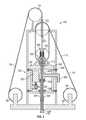
- FIG. 3illustrates an enlarged, partial, schematic view of the drilling rig 100 , according to an embodiment.
- the drilling apparatus 102may be suspended from the rig floor 108 via interaction with the travelling block 105 , the crown block 112 , and the drilling line 116 that is spooled on the drawworks 114 .
- the instrument 126is shown suspended from the drilling rig 100 by the instrument line 120 ; however, it will be appreciated that any of the aforementioned instruments (e.g., drill string logging tools 126 , 127 , and/or 200 ), and/or others, may be employed.
- the drilling apparatus 102may include a drilling device 300 , e.g., a top drive.
- the drilling device 300may include a housing 302 and a shaft 304 , which may be coupled to and extend out of the housing 302 .
- the shaft 304may be rotatably coupled to the housing 302 via a thrust bearing 306 .
- the shaft 304may be drive to rotate by a motor 307 , which may be coupled to and/or disposed within the housing 302 .
- the shaft 304may be connected to the drill string 104 , such that rotation of the shaft 304 may cause the drill string 104 to rotate.
- the housing 302By such connection between the shaft 304 and the drill string 104 , at least a portion of the weight of the drill string 104 may be supported by the housing 302 , which transmits the weight to the rig floor 108 via the crown block 112 and the support structure 110 , as well as the drawworks 114 .
- the drilling device 300may also include one or more rollers 308 (four are shown), which may transmit reactionary torque loads to the support structure 110 .
- the housing 302may further include an entry port 310 , through which the instrument line 120 may be received.
- the drilling apparatus 102may include a sealing device 320 , through which the instrument line 120 may be received into the entry port 310 .
- the sealing device 320may be coupled to the housing 302 of the drilling device 300 , and may be movable therewith. Further, the sealing device 320 may have (e.g., be able to be operated in) at least two configurations. In a first configuration, the sealing device 320 may be configured to receive and seal with the instrument line 120 . The instrument line 120 may be able to slide relative to the sealing device 320 when the sealing device 320 is in the first configuration, but fluid may be prevented from proceeding through the entry port 310 by the sealing device 320 .
- the sealing device 320may completely seal the entry port 310 , e.g., when the instrument line 120 is not received therethrough.
- the sealing device 320may function similarly to a blowout preventer does for the drill string 104 , serving to control access into the entry port 310 .
- the entry port 310may communicate with an interior 350 of the shaft 304 , e.g., via a conduit 353 within the housing 302 .
- the shaft 304may be rotatably coupled to the conduit 353 via swivel 354 , as shown. Accordingly, the instrument line 120 , when received through the entry port 310 , may proceed through the conduit 353 and into the shaft 304 , and then into the drill string 104 .
- the drilling device 300may also receive a flow of drilling mud via a mud conduit 360 .
- the mud conduit 360may communicate with the conduit 353 within the housing 302 , and thus the mud conduit 360 may be in fluid communication with the entry port 310 , as well as the interior 350 of the shaft 304 and the drill string 104 .
- the sealing device 320may serve to prevent mud flow up through the entry port 310 in either or both of the first and second configurations thereof.
- the drilling apparatus 102may further include a line-pusher 365 .
- the line-pusher 365may be configured to apply a downwardly-directed force on the instrument line 120 , which may cause the instrument line 120 to be directed downward, through the sealing device 320 , the entry port 310 , the conduit 353 , the interior 352 of the shaft 304 , and through at least a portion of the drill string 104 , so as to deploy the instrument 126 ( FIG. 1 ) therein.
- the line-pusher 365may be coupled to the housing 302 of the drilling device 300 and may be movable therewith.
- the line-pusher 365may be directly attached to the sealing device 320 , e.g., such that the sealing device 320 is positioned between the housing 302 and the line-pusher 365 .
- the line-pusher 365may be configured to push the instrument line 120 through the entry port 310 via the sealing device 320 .
- the line-pusher 365may be employed to overcome initial fluid resistance provided by the drilling mud coursing through the mud conduit 360 . Further, the line-pusher 365 may provide for rapid deployment of the instrument line 120 through the drill string 104 , e.g., faster than the velocity of the drilling mud therein, and thus the line-pusher 365 may overcome drag forces of the instrument 126 and the drilling line 116 in contact with the mud.
- the drilling apparatus 102may also include a pivotable guide 370 , through which the instrument line 120 may be received.
- the pivotable guide 370may be positioned, as proceeding along the line 120 , between the line sheave 124 and the line-pusher 365 .
- the pivotable guide 370may be movable across a range of positions, for example, between a first position, shown with solid lines, and a second position, shown with dashed lines. In the first position, the pivotable guide 370 may direct the instrument line 120 between the sheaves of the crown block 112 and between the sheaves of the travelling block 105 and toward the entry port 310 . In the second position, the pivotable guide 370 may direct the instrument line 120 away from the entry port 310 .
- the second positionmay be employed when raising the drilling device 300 so as to accept a new stand of tubulars on the drill string 104 and/or when initially running the instrument 126 and the instrument line 120 into the entry port 310 , as will be described in greater detail below.
- FIG. 4illustrates a flowchart a method 400 for acquiring data within a drill string 104 , according to an embodiment.
- the present method 400is described with reference to the drilling rig 100 discussed above, it will be appreciated that this is merely an example, and embodiments of the method 400 may be applied using other structures.
- the method 400may begin by deploying an instrument (e.g., one or more of the drill string logging tools 126 , 127 and/or 200 ) into the drill string 104 , as at 402 .
- the instrumentmay be deployed via the entry port 310 in the drilling device 300 and the associated components described above.
- the sealing device 220may be employed to selectively seal the entry port 310 , e.g., when the instrument line 120 is received therethrough.
- the drill string 104may be coupled to the bottom-hole assembly 109 and may be rotated or otherwise operated by the drilling device 300 .
- the method 400may also include performing drilling operations (e.g., drilling the wellbore 106 ) using the drill string 104 and the bottom-hole assembly 109 , as at 404 , which may occur at the same time that the instrument is deployed within the drill string at 402 .
- drilling operationse.g., drilling the wellbore 106
- the method 400may then include acquiring data using the instrument located in the drill string 104 , with the data being related to the formation 107 in which the wellbore 106 extends, as at 406 .
- data acquisitionmay include sensing one or more seismic waves generated by a seismic source 150 , as at 408 .
- the instrumentmay be or include a geophone, or several geophones.
- such data acquisitionmay include sensing a current or voltage differential in the drill string 104 using the instrument.
- the method 400may include generating an electromagnetic signal that propagates in the formation 107 and measuring either current or voltage drop along the drill string 104 using the drill string logging tool.
- the electromagnetic signalmay originate from the surface electrode 202 or the e-mag signal generator 204 located in the bottom-hole assembly 109 or elsewhere.
- the method 400may include determining a location of a resistivity boundary 209 in the formation 107 based on the measured either current or voltage drop along the drill string 104 .
- such locationmay be determined by comparing the voltage drop across two different portions of the drill string 104 (e.g., a first portion and a second portion located at different, e.g., adjacent, depths along the drill string 104 ).
- a greater voltage drop in one portion relative to the othermay indicate a greater current density, and thus reveal that the drill string 104 portion being measured is part of a preferential flowpath for current proceeding through the formation 107 .
- a lower voltage dropmay indicate a lower current density, and thus reveal that the drill string 104 section being measured is not part (e.g., below or above) the preferential flowpath for the current proceeding through the formation. From this determination, inferences about the existence and location of resistivity boundaries 209 may be made.
- forward modelingmay be employed to determine interface locations and/or resistivities in the formation based on the current detected in the drill string 104 .
- a current density in the drill stringmay be measured, e.g., at several locations, using the instrument in the drill string 104 .
- a processormay include modeling software, which may predict current propagation in the drill string 104 based on one or more predicted interface locations and resistivities of layers in the formation. Accordingly, the processor may determine a modeled current density at the several positions along the drill string.
- the methodmay then include determining a match between the modeled current density and measured current density, and then selecting one or more formation interface locations form the plurality of interface locations, and one or more resistivities form the plurality of resistivities, based on the determined match.
- the method 400may also include transmitting data from the drill string logging tool to the controller 128 at the surface, as at 412 .
- Such transmissionmay be wired, e.g., through the instrument line 120 .
- the measurement with the logging tool 126 , 127may be performed during any operations performed using the drill string 104 and the drilling rig 100 .
- such operationsmay include drilling, tripping, and/or reaming. This means that data acquisition may occur while the drill string 104 is rotating, moving axially in the wellbore, and/or when mud is flowing inside the drill string 104 .
- FIG. 5illustrates an example of such a computing system 500 , in accordance with some embodiments.
- the computing system 500may include a computer or computer system 501 A, which may be an individual computer system 501 A or an arrangement of distributed computer systems.
- the computer system 501 Aincludes one or more analysis modules 502 that are configured to perform various tasks according to some embodiments, such as one or more methods disclosed herein. To perform these various tasks, the analysis module 502 executes independently, or in coordination with, one or more processors 504 , which is (or are) connected to one or more storage media 506 .
- the processor(s) 504is (or are) also connected to a network interface 507 to allow the computer system 501 A to communicate over a data network 509 with one or more additional computer systems and/or computing systems, such as 501 B, 501 C, and/or 501 D (note that computer systems 501 B, 501 C and/or 501 D may or may not share the same architecture as computer system 501 A, and may be located in different physical locations, e.g., computer systems 501 A and 501 B may be located in a processing facility, while in communication with one or more computer systems such as 501 C and/or 501 D that are located in one or more data centers, and/or located in varying countries on different continents).
- a processormay include a microprocessor, microcontroller, processor module or subsystem, programmable integrated circuit, programmable gate array, or another control or computing device.
- the storage media 506may be implemented as one or more computer-readable or machine-readable storage media. Note that while in the example embodiment of FIG. 5 storage media 506 is depicted as within computer system 501 A, in some embodiments, storage media 506 may be distributed within and/or across multiple internal and/or external enclosures of computing system 501 A and/or additional computing systems.
- Storage media 506may include one or more different forms of memory including semiconductor memory devices such as dynamic or static random access memories (DRAMs or SRAMs), erasable and programmable read-only memories (EPROMs), electrically erasable and programmable read-only memories (EEPROMs) and flash memories, magnetic disks such as fixed, floppy and removable disks, other magnetic media including tape, optical media such as compact disks (CDs) or digital video disks (DVDs), BLU-RAY® disks, or other types of optical storage, or other types of storage devices.
- semiconductor memory devicessuch as dynamic or static random access memories (DRAMs or SRAMs), erasable and programmable read-only memories (EPROMs), electrically erasable and programmable read-only memories (EEPROMs) and flash memories
- magnetic diskssuch as fixed, floppy and removable disks, other magnetic media including tape
- optical mediasuch as compact disks (CDs) or digital video disks (DVDs), BLU-RAY® disks,
- Such computer-readable or machine-readable storage medium or mediais (are) considered to be part of an article (or article of manufacture).
- An article or article of manufacturemay refer to any manufactured single component or multiple components.
- the storage medium or mediamay be located either in the machine running the machine-readable instructions, or located at a remote site from which machine-readable instructions may be downloaded over a network for execution.
- the computing system 500contains one or more rig control module(s) 508 .
- computer system 501 Aincludes the rig control module 508 .
- a single rig control modulemay be used to perform some or all aspects of one or more embodiments of the methods disclosed herein.
- a plurality of rig control modulesmay be used to perform some or all aspects of methods herein.
- the computing system 500is one example of a computing system; in other examples, the computing system 500 may have more or fewer components than shown, may combine additional components not depicted in the example embodiment of FIG. 5 , and/or the computing system 500 may have a different configuration or arrangement of the components depicted in FIG. 5 .
- the various components shown in FIG. 5may be implemented in hardware, software, or a combination of both hardware and software, including one or more signal processing and/or application specific integrated circuits.
- steps in the processing methods described hereinmay be implemented by running one or more functional modules in information processing apparatus such as general purpose processors or application specific chips, such as ASICs, FPGAs, PLDs, or other appropriate devices.
- information processing apparatussuch as general purpose processors or application specific chips, such as ASICs, FPGAs, PLDs, or other appropriate devices.
Landscapes
- Engineering & Computer Science (AREA)
- Geology (AREA)
- Life Sciences & Earth Sciences (AREA)
- Mining & Mineral Resources (AREA)
- Physics & Mathematics (AREA)
- Environmental & Geological Engineering (AREA)
- Fluid Mechanics (AREA)
- General Life Sciences & Earth Sciences (AREA)
- Geochemistry & Mineralogy (AREA)
- Remote Sensing (AREA)
- Geophysics (AREA)
- Geophysics And Detection Of Objects (AREA)
- Acoustics & Sound (AREA)
Abstract
Description
Claims (3)
Priority Applications (1)
| Application Number | Priority Date | Filing Date | Title |
|---|---|---|---|
| US15/097,724US10753198B2 (en) | 2015-04-13 | 2016-04-13 | Downhole instrument for deep formation imaging deployed within a drill string |
Applications Claiming Priority (3)
| Application Number | Priority Date | Filing Date | Title |
|---|---|---|---|
| US201562146731P | 2015-04-13 | 2015-04-13 | |
| US201562147246P | 2015-04-14 | 2015-04-14 | |
| US15/097,724US10753198B2 (en) | 2015-04-13 | 2016-04-13 | Downhole instrument for deep formation imaging deployed within a drill string |
Publications (2)
| Publication Number | Publication Date |
|---|---|
| US20160298449A1 US20160298449A1 (en) | 2016-10-13 |
| US10753198B2true US10753198B2 (en) | 2020-08-25 |
Family
ID=57112543
Family Applications (1)
| Application Number | Title | Priority Date | Filing Date |
|---|---|---|---|
| US15/097,724Expired - Fee RelatedUS10753198B2 (en) | 2015-04-13 | 2016-04-13 | Downhole instrument for deep formation imaging deployed within a drill string |
Country Status (2)
| Country | Link |
|---|---|
| US (1) | US10753198B2 (en) |
| WO (1) | WO2016168291A1 (en) |
Cited By (1)
| Publication number | Priority date | Publication date | Assignee | Title |
|---|---|---|---|---|
| US20230341929A1 (en)* | 2017-06-28 | 2023-10-26 | Halliburton Energy Services, Inc. | Interactive virtual reality manipulation of downhole data |
Families Citing this family (9)
| Publication number | Priority date | Publication date | Assignee | Title |
|---|---|---|---|---|
| US10753198B2 (en)* | 2015-04-13 | 2020-08-25 | Schlumberger Technology Corporation | Downhole instrument for deep formation imaging deployed within a drill string |
| US10900305B2 (en) | 2015-04-13 | 2021-01-26 | Schlumberger Technology Corporation | Instrument line for insertion in a drill string of a drilling system |
| WO2016168322A1 (en) | 2015-04-13 | 2016-10-20 | Schlumberger Technology Corporation | Top drive with top entry and line inserted therethrough for data gathering through the drill string |
| US11723579B2 (en) | 2017-09-19 | 2023-08-15 | Neuroenhancement Lab, LLC | Method and apparatus for neuroenhancement |
| US11717686B2 (en) | 2017-12-04 | 2023-08-08 | Neuroenhancement Lab, LLC | Method and apparatus for neuroenhancement to facilitate learning and performance |
| US11273283B2 (en) | 2017-12-31 | 2022-03-15 | Neuroenhancement Lab, LLC | Method and apparatus for neuroenhancement to enhance emotional response |
| US12280219B2 (en) | 2017-12-31 | 2025-04-22 | NeuroLight, Inc. | Method and apparatus for neuroenhancement to enhance emotional response |
| US11364361B2 (en) | 2018-04-20 | 2022-06-21 | Neuroenhancement Lab, LLC | System and method for inducing sleep by transplanting mental states |
| EP3849410A4 (en) | 2018-09-14 | 2022-11-02 | Neuroenhancement Lab, LLC | SLEEP ENHANCEMENT SYSTEM AND METHOD |
Citations (95)
| Publication number | Priority date | Publication date | Assignee | Title |
|---|---|---|---|---|
| US2557168A (en)* | 1949-11-28 | 1951-06-19 | Jan J Arps | Continuous electric logging while drilling |
| US2677427A (en) | 1951-02-06 | 1954-05-04 | Shell Dev | Cable injecting device |
| US2906342A (en) | 1956-03-21 | 1959-09-29 | Jersey Prod Res Co | Well assembly for production of fluids from a plurality of zones |
| US2963092A (en) | 1956-08-29 | 1960-12-06 | Jersey Prod Res Co | Testing tool |
| US3167707A (en) | 1960-12-29 | 1965-01-26 | Seismograph Service Corp | Well logging apparatus having laterally shiftable wall engageable electrode supports |
| US3363880A (en) | 1966-11-14 | 1968-01-16 | Schiumberger Technology Corp | Cable-feeding apparatus |
| US4003435A (en) | 1975-10-09 | 1977-01-18 | General Electric Company | Method and apparatus for deployment and retrieval of fixed lengths of electrical cable into and from a well bore |
| US4090573A (en) | 1976-08-18 | 1978-05-23 | Petro-Data C.A. | Wireline sealing apparatus and method for use with a drill string |
| US4126848A (en) | 1976-12-23 | 1978-11-21 | Shell Oil Company | Drill string telemeter system |
| US4143721A (en) | 1977-10-03 | 1979-03-13 | Scientific Drilling Controls | Change in length of drill string containing an instrument |
| US4153120A (en) | 1977-10-03 | 1979-05-08 | Scientific Drilling Controls | Change in length of drill string while instrument remains therein |
| US4325438A (en) | 1980-03-24 | 1982-04-20 | Scientific Drilling Controls | Lengthening drill string containing an instrument |
| US4331203A (en) | 1980-09-25 | 1982-05-25 | Trw Inc. | Method and apparatus for the installation and withdrawal of pumping equipment in an underwater well |
| US4578675A (en)* | 1982-09-30 | 1986-03-25 | Macleod Laboratories, Inc. | Apparatus and method for logging wells while drilling |
| US4689775A (en) | 1980-01-10 | 1987-08-25 | Scherbatskoy Serge Alexander | Direct radiator system and methods for measuring during drilling operations |
| US4739325A (en)* | 1982-09-30 | 1988-04-19 | Macleod Laboratories, Inc. | Apparatus and method for down-hole EM telemetry while drilling |
| US4857831A (en) | 1986-12-29 | 1989-08-15 | Schlumberger Technology Corporation | Borehole casing diagnostic apparatus and method |
| US4965774A (en)* | 1989-07-26 | 1990-10-23 | Atlantic Richfield Company | Method and system for vertical seismic profiling by measuring drilling vibrations |
| US5095993A (en) | 1989-12-15 | 1992-03-17 | Schlumberger Technology Corporation | Anchor apparatus for a tubing and wireline conveyed method and apparatus |
| US5107705A (en) | 1990-03-30 | 1992-04-28 | Schlumberger Technology Corporation | Video system and method for determining and monitoring the depth of a bottomhole assembly within a wellbore |
| US5305830A (en)* | 1991-08-02 | 1994-04-26 | Institut Francais Du Petrole | Method and device for carrying out measurings and/or servicings in a wellbore or a well in the process of being drilled |
| US5426368A (en) | 1992-02-12 | 1995-06-20 | Schlumberger Technology Corporation | Logging method and apparatus for investigating geometrical characteristics of a borehole and for investigating formation resistivity |
| US5468153A (en) | 1993-12-15 | 1995-11-21 | Drilling Measurements, Inc. | Wireline swivel and method of use |
| US5735351A (en) | 1995-03-27 | 1998-04-07 | Helms; Charles M. | Top entry apparatus and method for a drilling assembly |
| US5823257A (en) | 1996-10-04 | 1998-10-20 | Peyton; Mark Alan | Rotatable wet connect for downhole logging devices |
| US5881310A (en)* | 1990-07-16 | 1999-03-09 | Atlantic Richfield Company | Method for executing an instruction where the memory locations for data, operation to be performed and storing of the result are indicated by pointers |
| US6138756A (en) | 1998-01-09 | 2000-10-31 | Halliburton Energy Services, Inc. | Milling guide having orientation and depth determination capabilities |
| US6250402B1 (en)* | 1997-04-16 | 2001-06-26 | Digital Control Incorporated | Establishing positions of locating field detectors and path mappings in underground boring tool applications |
| US6341654B1 (en) | 1999-04-15 | 2002-01-29 | Weatherford/Lamb, Inc. | Inflatable packer setting tool assembly |
| US6396276B1 (en)* | 1996-07-31 | 2002-05-28 | Scientific Drilling International | Apparatus and method for electric field telemetry employing component upper and lower housings in a well pipestring |
| US20020070030A1 (en) | 1999-12-08 | 2002-06-13 | Smith Leslie Dean | Wellhead with improved ESP cable pack-off and method |
| US20020070033A1 (en) | 1999-01-19 | 2002-06-13 | Headworth Colin Stuart | System for accessing oil wells with compliant guide and coiled tubing |
| WO2004086093A1 (en)* | 2003-03-20 | 2004-10-07 | Baker Hughes Incorporated | Use of pattern recognition in a measurement of formation transit time for seismic checkshots |
| US20050046588A1 (en) | 2003-08-27 | 2005-03-03 | Wisler Macmillan | Electromagnetic MWD telemetry system incorporating a current sensing transformer |
| US20050115708A1 (en) | 2003-12-01 | 2005-06-02 | Jabusch Kirby D. | Method and system for transmitting signals through a metal tubular |
| WO2005064114A1 (en) | 2003-12-19 | 2005-07-14 | Baker Hughes Incorporated | Method and apparatus for enhancing directional accuracy and control using bottomhole assembly bending measurements |
| US20060119364A1 (en) | 2003-12-02 | 2006-06-08 | Schlumberger Technology Corporation | Insulated sleeve with conductive electrodes to reduce borehole effects for an induction tool |
| US20070056722A1 (en) | 2005-07-19 | 2007-03-15 | Tesco Corporation | Wireline entry sub |
| US20070181304A1 (en)* | 2006-02-08 | 2007-08-09 | Rankin E Edward | Method and Apparatus for Completing a Horizontal Well |
| US20070215343A1 (en) | 2005-11-30 | 2007-09-20 | Mcdonald William J | Wellbore Motor Having Magnetic Gear Drive |
| US20070247328A1 (en)* | 2006-04-21 | 2007-10-25 | John Petrovic | System and Method For Downhole Telemetry |
| US20080006400A1 (en) | 2004-09-24 | 2008-01-10 | Coyle William E Jr | Arm for moving flexible lines at a wellsite |
| US20080066905A1 (en) | 2006-09-14 | 2008-03-20 | Aivalis James G | Coiled tubing wellbore drilling and surveying using a through the drill bit apparatus |
| US7377317B2 (en) | 2005-04-12 | 2008-05-27 | Precision Energy Services, Inc. | Apparatus and methods for logging a well borehole with controllable rotating instrumentation |
| US20080159077A1 (en) | 2006-12-29 | 2008-07-03 | Raghu Madhavan | Cable link for a wellbore telemetry system |
| US20080156477A1 (en) | 2006-12-28 | 2008-07-03 | Thrubit Llc | Deployment tool for well logging instruments conveyed through the interior of a pipe string |
| US20080196904A1 (en) | 2007-01-12 | 2008-08-21 | Tesco Corporation | Wireline entry sub |
| US20080216554A1 (en) | 2007-03-07 | 2008-09-11 | Mckee L Michael | Downhole Load Cell |
| US20080230216A1 (en) | 2005-07-19 | 2008-09-25 | Tesco Corporation | Wireline Entry Sub |
| US20080271924A1 (en)* | 2007-03-02 | 2008-11-06 | Schlumberger Technology Corporation | Drilling Method and Apparatus |
| US20090012711A1 (en) | 2005-03-09 | 2009-01-08 | Geo-X System, Ltd. | Vertical seismic profiling method utilizing seismic communication and synchronization |
| US20090038850A1 (en)* | 2007-08-07 | 2009-02-12 | Brune Guenter W | Advanced Steering Tool System, Method and Apparatus |
| WO2009085348A2 (en) | 2007-12-21 | 2009-07-09 | Services Petroliers Schlumberger | Logging tool deployment systems and methods with pressure compensation |
| US20090277631A1 (en) | 2008-05-08 | 2009-11-12 | James Minto | Rotator for wireline conveyed wellbore instruments and method for rotating an instrument in a wellbore |
| US20090321174A1 (en) | 2008-06-25 | 2009-12-31 | Schlumberger Technology Corporation | Method and apparatus for deploying a plurality of seismic devices into a borehole and method thereof |
| US20100065329A1 (en)* | 2008-08-15 | 2010-03-18 | Zientarski Mariusz Thomas | Downhole telemetry apparatus and method |
| US20100206544A1 (en) | 2009-02-18 | 2010-08-19 | Schlumberger Technology Corporation | Integrated Cable Hanger Pick-Up System |
| US20100328096A1 (en) | 2005-09-16 | 2010-12-30 | Intelliserv, LLC. | Wellbore telemetry system and method |
| US20110005767A1 (en) | 2007-11-09 | 2011-01-13 | Muff Anthony D | Riser system comprising pressure control means |
| US8044819B1 (en)* | 2006-10-23 | 2011-10-25 | Scientific Drilling International | Coal boundary detection using an electric-field borehole telemetry apparatus |
| US20110280104A1 (en) | 2010-03-05 | 2011-11-17 | Mcclung Iii Guy L | Dual top drive systems and methods for wellbore operations |
| US20110277990A1 (en) | 2007-11-15 | 2011-11-17 | Spyro Kotsonis | Anchoring systems for drilling tools |
| US20110315445A1 (en) | 2008-10-16 | 2011-12-29 | Thrubit B.V. | Methods for Installling Sensors in a Borehole |
| US20120068528A1 (en) | 2009-05-14 | 2012-03-22 | Sandvik Mining And Construction G.M.B.H | Cutting device for a mining machine |
| WO2012058296A2 (en) | 2010-10-26 | 2012-05-03 | Baker Hughes Incorporated | Downhole tool deployment measurement method and apparatus |
| US20120197528A1 (en) | 2011-01-28 | 2012-08-02 | Baker Hughes Incorporated | Method and apparatus for transmitting a dataset from a tool to a receiver |
| US20120230151A1 (en) | 2007-12-26 | 2012-09-13 | Almaguer James S | Borehole Imaging And Orientation Of Downhole Tools |
| US20130068528A1 (en) | 2010-06-04 | 2013-03-21 | Ian Gray | Through The Drill String or Core Bit DST System |
| US20130118807A1 (en)* | 2011-11-15 | 2013-05-16 | Saudi Arabian Oil Company | Methods For Geosteering A Drill Bit In Real Time Using Drilling Acoustic Signals |
| US8474548B1 (en) | 2005-09-12 | 2013-07-02 | Teledrift Company | Measurement while drilling apparatus and method of using the same |
| US20140121974A1 (en)* | 2012-11-01 | 2014-05-01 | Gregory Itskovich | Apparatus and method for deep transient resistivity measurement |
| CA2891162A1 (en)* | 2012-11-20 | 2014-05-30 | Halliburton Energy Services, Inc. | Acoustic signal enhancement apparatus, systems, and methods |
| US20140190686A1 (en) | 2013-01-04 | 2014-07-10 | Sandia Corporation | Electrically Conductive Proppant and Methods for Detecting, Locating and Characterizing the Electrically Conductive Proppant |
| US20140265565A1 (en) | 2013-03-15 | 2014-09-18 | Fastcap Systems Corporation | Modular signal interface devices and related downhole power and data systems |
| US20140308105A1 (en) | 2011-12-01 | 2014-10-16 | Wellpartner Products As | Method and an Apparatus for Rigging Up Intervention Equipment in a Lifting Arrangement Utilized on a Floating Vessel |
| CA2914552A1 (en)* | 2013-06-06 | 2014-12-11 | Norwegian University Of Science And Technology (Ntnu) | Drilling method and apparatus |
| US20150012217A1 (en) | 2011-12-23 | 2015-01-08 | Schlumberger Technology Corporation | System and Methods for Measuring Borehole Caliper in Oil-Based Mud |
| US20150070185A1 (en) | 2013-08-07 | 2015-03-12 | Baker Hughes Incorporated | Apparatus and method for drill pipe transmission line connections |
| US20150090459A1 (en) | 2013-10-01 | 2015-04-02 | Bp Corporation North America Inc. | Apparatus and Methods for Clearing a Subsea Tubular |
| US20150247399A1 (en) | 2012-09-21 | 2015-09-03 | Halliburton Energy Services, Inc. | System and method for determining drilling parameters based on hydraulic pressure associated with a directional drilling system |
| US20150300161A1 (en)* | 2014-04-22 | 2015-10-22 | Schlumberger Technology Corporation | Down Hole Subsurface Wave System with Drill String Wave Discrimination and Method of Using Same |
| US20150337650A1 (en)* | 2014-05-20 | 2015-11-26 | Aps Technology, Inc. | Telemetry system, current sensor, and related methods for a drilling system |
| US20160061027A1 (en)* | 2014-08-27 | 2016-03-03 | Schlumberger Technology Corporation | Electromagnetic Telemetry for Measurement and Logging While Drilling and Magnetic Ranging Between Wellbores |
| US20160291192A1 (en)* | 2013-11-27 | 2016-10-06 | Westerngeco Llc | Current density inversion |
| US20160298442A1 (en)* | 2015-04-13 | 2016-10-13 | Schlumberger Technology Corporation | Instrument line for insertion in a drill string of a drilling system |
| US20160298441A1 (en)* | 2015-04-13 | 2016-10-13 | Schlumberger Technology Corporation | Top drive with top entry and line inserted therethrough for data gathering through the drill string |
| US20160298449A1 (en)* | 2015-04-13 | 2016-10-13 | Schlumberger Technology Corporation | Downhole instrument for deep formation imaging deployed within a drill string |
| US9512716B2 (en)* | 2013-03-05 | 2016-12-06 | Evolution Engineering Inc. | System and method for regulating an electromagnetic telemetry signal sent from downhole to surface |
| US20170097441A1 (en)* | 2015-10-06 | 2017-04-06 | Groundmetrics, Inc. | System and Method for Performing Distant Geophysical Survey |
| US20170111112A1 (en)* | 2014-06-25 | 2017-04-20 | Halliburton Energy Services, Inc. | Optically Obtaining Gravitational Field Measurements in a Downhole or Subsea Environment |
| US9759830B2 (en) | 2013-10-30 | 2017-09-12 | Schlumberger Technology Corporation | Method and apparatus for determining mud contamination of formation fluid |
| US9765613B2 (en) | 2014-03-03 | 2017-09-19 | Aps Technology, Inc. | Drilling system and electromagnetic telemetry tool with an electrical connector assembly and associated methods |
| US20180045559A1 (en)* | 2015-02-27 | 2018-02-15 | Schlumberger Technology Corporation | Seismic investigations using seismic sensor |
| US20180156023A1 (en) | 2016-02-18 | 2018-06-07 | Halliburton Energy Services, Inc | Method and system for distributed control of drilling operations |
| US10119393B2 (en) | 2014-06-23 | 2018-11-06 | Evolution Engineering Inc. | Optimizing downhole data communication with at bit sensors and nodes |
- 2016
- 2016-04-13USUS15/097,724patent/US10753198B2/ennot_activeExpired - Fee Related
- 2016-04-13WOPCT/US2016/027276patent/WO2016168291A1/ennot_activeCeased
Patent Citations (109)
| Publication number | Priority date | Publication date | Assignee | Title |
|---|---|---|---|---|
| US2557168A (en)* | 1949-11-28 | 1951-06-19 | Jan J Arps | Continuous electric logging while drilling |
| US2677427A (en) | 1951-02-06 | 1954-05-04 | Shell Dev | Cable injecting device |
| US2906342A (en) | 1956-03-21 | 1959-09-29 | Jersey Prod Res Co | Well assembly for production of fluids from a plurality of zones |
| US2963092A (en) | 1956-08-29 | 1960-12-06 | Jersey Prod Res Co | Testing tool |
| US3167707A (en) | 1960-12-29 | 1965-01-26 | Seismograph Service Corp | Well logging apparatus having laterally shiftable wall engageable electrode supports |
| US3363880A (en) | 1966-11-14 | 1968-01-16 | Schiumberger Technology Corp | Cable-feeding apparatus |
| US4003435A (en) | 1975-10-09 | 1977-01-18 | General Electric Company | Method and apparatus for deployment and retrieval of fixed lengths of electrical cable into and from a well bore |
| US4090573A (en) | 1976-08-18 | 1978-05-23 | Petro-Data C.A. | Wireline sealing apparatus and method for use with a drill string |
| US4126848A (en) | 1976-12-23 | 1978-11-21 | Shell Oil Company | Drill string telemeter system |
| US4143721A (en) | 1977-10-03 | 1979-03-13 | Scientific Drilling Controls | Change in length of drill string containing an instrument |
| US4153120A (en) | 1977-10-03 | 1979-05-08 | Scientific Drilling Controls | Change in length of drill string while instrument remains therein |
| US4689775A (en) | 1980-01-10 | 1987-08-25 | Scherbatskoy Serge Alexander | Direct radiator system and methods for measuring during drilling operations |
| US4325438A (en) | 1980-03-24 | 1982-04-20 | Scientific Drilling Controls | Lengthening drill string containing an instrument |
| US4331203A (en) | 1980-09-25 | 1982-05-25 | Trw Inc. | Method and apparatus for the installation and withdrawal of pumping equipment in an underwater well |
| US4578675A (en)* | 1982-09-30 | 1986-03-25 | Macleod Laboratories, Inc. | Apparatus and method for logging wells while drilling |
| US4739325A (en)* | 1982-09-30 | 1988-04-19 | Macleod Laboratories, Inc. | Apparatus and method for down-hole EM telemetry while drilling |
| US4857831A (en) | 1986-12-29 | 1989-08-15 | Schlumberger Technology Corporation | Borehole casing diagnostic apparatus and method |
| US4965774A (en)* | 1989-07-26 | 1990-10-23 | Atlantic Richfield Company | Method and system for vertical seismic profiling by measuring drilling vibrations |
| US5095993A (en) | 1989-12-15 | 1992-03-17 | Schlumberger Technology Corporation | Anchor apparatus for a tubing and wireline conveyed method and apparatus |
| US5107705A (en) | 1990-03-30 | 1992-04-28 | Schlumberger Technology Corporation | Video system and method for determining and monitoring the depth of a bottomhole assembly within a wellbore |
| US5881310A (en)* | 1990-07-16 | 1999-03-09 | Atlantic Richfield Company | Method for executing an instruction where the memory locations for data, operation to be performed and storing of the result are indicated by pointers |
| US5305830A (en)* | 1991-08-02 | 1994-04-26 | Institut Francais Du Petrole | Method and device for carrying out measurings and/or servicings in a wellbore or a well in the process of being drilled |
| US5426368A (en) | 1992-02-12 | 1995-06-20 | Schlumberger Technology Corporation | Logging method and apparatus for investigating geometrical characteristics of a borehole and for investigating formation resistivity |
| US5468153A (en) | 1993-12-15 | 1995-11-21 | Drilling Measurements, Inc. | Wireline swivel and method of use |
| US5735351A (en) | 1995-03-27 | 1998-04-07 | Helms; Charles M. | Top entry apparatus and method for a drilling assembly |
| US6396276B1 (en)* | 1996-07-31 | 2002-05-28 | Scientific Drilling International | Apparatus and method for electric field telemetry employing component upper and lower housings in a well pipestring |
| US5823257A (en) | 1996-10-04 | 1998-10-20 | Peyton; Mark Alan | Rotatable wet connect for downhole logging devices |
| US20090255730A1 (en)* | 1997-04-16 | 2009-10-15 | Brune Guenter W | Establishing Positions of Locating Field Detectors and Path Mapping in Underground Boring Tool Applications |
| US20010022239A1 (en)* | 1997-04-16 | 2001-09-20 | Brune Guenter W. | Establishing positions of locating field detectors and path mapping in underground boring tool applications |
| US6250402B1 (en)* | 1997-04-16 | 2001-06-26 | Digital Control Incorporated | Establishing positions of locating field detectors and path mappings in underground boring tool applications |
| US20120085582A1 (en)* | 1997-04-16 | 2012-04-12 | Brune Guenter W | Establishing positions of locating field detectors and path mapping in underground boring tool applications |
| US20020096364A1 (en)* | 1997-04-16 | 2002-07-25 | Brune Guenter W. | Establishing positions of locating field detectors and path mapping in underground boring tool applications |
| US20030136583A1 (en)* | 1997-04-16 | 2003-07-24 | Brune Guenter W. | Establishing positions of locating field detectors and path mapping in underground boring tool applications |
| US20040084218A1 (en)* | 1997-04-16 | 2004-05-06 | Brune Guenter W. | Establishing positions of locating field detectors and path mapping in underground boring tool applications |
| US20140131103A1 (en)* | 1997-04-16 | 2014-05-15 | Merlin Technology Inc. | Establishing positions of locating field detectors and path mapping in underground boring tool applications |
| US20060124355A1 (en)* | 1997-04-16 | 2006-06-15 | Brune Guenter W | Establishing positions of locating field detectors and path mapping in underground boring tool applications |
| US20080121431A1 (en)* | 1997-04-16 | 2008-05-29 | Brune Guenter W | Establishing Positions of Locating Field Detectors and Path Mapping in Underground Boring Tool Applications |
| US6138756A (en) | 1998-01-09 | 2000-10-31 | Halliburton Energy Services, Inc. | Milling guide having orientation and depth determination capabilities |
| US20020070033A1 (en) | 1999-01-19 | 2002-06-13 | Headworth Colin Stuart | System for accessing oil wells with compliant guide and coiled tubing |
| US6341654B1 (en) | 1999-04-15 | 2002-01-29 | Weatherford/Lamb, Inc. | Inflatable packer setting tool assembly |
| US20020070030A1 (en) | 1999-12-08 | 2002-06-13 | Smith Leslie Dean | Wellhead with improved ESP cable pack-off and method |
| WO2004086093A1 (en)* | 2003-03-20 | 2004-10-07 | Baker Hughes Incorporated | Use of pattern recognition in a measurement of formation transit time for seismic checkshots |
| US20050052949A1 (en)* | 2003-03-20 | 2005-03-10 | Baker Hughes Incorporated | Use of pattern recognition in a measurement of formation transit time for seismic checkshots |
| US20050046588A1 (en) | 2003-08-27 | 2005-03-03 | Wisler Macmillan | Electromagnetic MWD telemetry system incorporating a current sensing transformer |
| US20050115708A1 (en) | 2003-12-01 | 2005-06-02 | Jabusch Kirby D. | Method and system for transmitting signals through a metal tubular |
| US20060119364A1 (en) | 2003-12-02 | 2006-06-08 | Schlumberger Technology Corporation | Insulated sleeve with conductive electrodes to reduce borehole effects for an induction tool |
| WO2005064114A1 (en) | 2003-12-19 | 2005-07-14 | Baker Hughes Incorporated | Method and apparatus for enhancing directional accuracy and control using bottomhole assembly bending measurements |
| US20050150689A1 (en) | 2003-12-19 | 2005-07-14 | Baker Hughes Incorporated | Method and apparatus for enhancing directional accuracy and control using bottomhole assembly bending measurements |
| US20080006400A1 (en) | 2004-09-24 | 2008-01-10 | Coyle William E Jr | Arm for moving flexible lines at a wellsite |
| US20090012711A1 (en) | 2005-03-09 | 2009-01-08 | Geo-X System, Ltd. | Vertical seismic profiling method utilizing seismic communication and synchronization |
| US7377317B2 (en) | 2005-04-12 | 2008-05-27 | Precision Energy Services, Inc. | Apparatus and methods for logging a well borehole with controllable rotating instrumentation |
| US20080230216A1 (en) | 2005-07-19 | 2008-09-25 | Tesco Corporation | Wireline Entry Sub |
| US20070056722A1 (en) | 2005-07-19 | 2007-03-15 | Tesco Corporation | Wireline entry sub |
| US8474548B1 (en) | 2005-09-12 | 2013-07-02 | Teledrift Company | Measurement while drilling apparatus and method of using the same |
| US20100328096A1 (en) | 2005-09-16 | 2010-12-30 | Intelliserv, LLC. | Wellbore telemetry system and method |
| US20070215343A1 (en) | 2005-11-30 | 2007-09-20 | Mcdonald William J | Wellbore Motor Having Magnetic Gear Drive |
| US20070181304A1 (en)* | 2006-02-08 | 2007-08-09 | Rankin E Edward | Method and Apparatus for Completing a Horizontal Well |
| US20070247328A1 (en)* | 2006-04-21 | 2007-10-25 | John Petrovic | System and Method For Downhole Telemetry |
| US20080066905A1 (en) | 2006-09-14 | 2008-03-20 | Aivalis James G | Coiled tubing wellbore drilling and surveying using a through the drill bit apparatus |
| US8044819B1 (en)* | 2006-10-23 | 2011-10-25 | Scientific Drilling International | Coal boundary detection using an electric-field borehole telemetry apparatus |
| US20080156477A1 (en) | 2006-12-28 | 2008-07-03 | Thrubit Llc | Deployment tool for well logging instruments conveyed through the interior of a pipe string |
| US20080159077A1 (en) | 2006-12-29 | 2008-07-03 | Raghu Madhavan | Cable link for a wellbore telemetry system |
| US20080196904A1 (en) | 2007-01-12 | 2008-08-21 | Tesco Corporation | Wireline entry sub |
| US20080271924A1 (en)* | 2007-03-02 | 2008-11-06 | Schlumberger Technology Corporation | Drilling Method and Apparatus |
| US20080216554A1 (en) | 2007-03-07 | 2008-09-11 | Mckee L Michael | Downhole Load Cell |
| US20090038850A1 (en)* | 2007-08-07 | 2009-02-12 | Brune Guenter W | Advanced Steering Tool System, Method and Apparatus |
| US20110005767A1 (en) | 2007-11-09 | 2011-01-13 | Muff Anthony D | Riser system comprising pressure control means |
| US20110277990A1 (en) | 2007-11-15 | 2011-11-17 | Spyro Kotsonis | Anchoring systems for drilling tools |
| WO2009085348A2 (en) | 2007-12-21 | 2009-07-09 | Services Petroliers Schlumberger | Logging tool deployment systems and methods with pressure compensation |
| US20120230151A1 (en) | 2007-12-26 | 2012-09-13 | Almaguer James S | Borehole Imaging And Orientation Of Downhole Tools |
| US20090277631A1 (en) | 2008-05-08 | 2009-11-12 | James Minto | Rotator for wireline conveyed wellbore instruments and method for rotating an instrument in a wellbore |
| US20090321174A1 (en) | 2008-06-25 | 2009-12-31 | Schlumberger Technology Corporation | Method and apparatus for deploying a plurality of seismic devices into a borehole and method thereof |
| US20100065329A1 (en)* | 2008-08-15 | 2010-03-18 | Zientarski Mariusz Thomas | Downhole telemetry apparatus and method |
| US8863861B2 (en)* | 2008-08-15 | 2014-10-21 | Mariusz Thomas ZIENTARSKI | Downhole telemetry apparatus and method |
| US20110315445A1 (en) | 2008-10-16 | 2011-12-29 | Thrubit B.V. | Methods for Installling Sensors in a Borehole |
| US20100206544A1 (en) | 2009-02-18 | 2010-08-19 | Schlumberger Technology Corporation | Integrated Cable Hanger Pick-Up System |
| US20120068528A1 (en) | 2009-05-14 | 2012-03-22 | Sandvik Mining And Construction G.M.B.H | Cutting device for a mining machine |
| US20110280104A1 (en) | 2010-03-05 | 2011-11-17 | Mcclung Iii Guy L | Dual top drive systems and methods for wellbore operations |
| US20130068528A1 (en) | 2010-06-04 | 2013-03-21 | Ian Gray | Through The Drill String or Core Bit DST System |
| WO2012058296A2 (en) | 2010-10-26 | 2012-05-03 | Baker Hughes Incorporated | Downhole tool deployment measurement method and apparatus |
| US20120197528A1 (en) | 2011-01-28 | 2012-08-02 | Baker Hughes Incorporated | Method and apparatus for transmitting a dataset from a tool to a receiver |
| US20130118807A1 (en)* | 2011-11-15 | 2013-05-16 | Saudi Arabian Oil Company | Methods For Geosteering A Drill Bit In Real Time Using Drilling Acoustic Signals |
| US20140308105A1 (en) | 2011-12-01 | 2014-10-16 | Wellpartner Products As | Method and an Apparatus for Rigging Up Intervention Equipment in a Lifting Arrangement Utilized on a Floating Vessel |
| US20150012217A1 (en) | 2011-12-23 | 2015-01-08 | Schlumberger Technology Corporation | System and Methods for Measuring Borehole Caliper in Oil-Based Mud |
| US20150247399A1 (en) | 2012-09-21 | 2015-09-03 | Halliburton Energy Services, Inc. | System and method for determining drilling parameters based on hydraulic pressure associated with a directional drilling system |
| US20140121974A1 (en)* | 2012-11-01 | 2014-05-01 | Gregory Itskovich | Apparatus and method for deep transient resistivity measurement |
| CA2891162A1 (en)* | 2012-11-20 | 2014-05-30 | Halliburton Energy Services, Inc. | Acoustic signal enhancement apparatus, systems, and methods |
| US20140190686A1 (en) | 2013-01-04 | 2014-07-10 | Sandia Corporation | Electrically Conductive Proppant and Methods for Detecting, Locating and Characterizing the Electrically Conductive Proppant |
| US9512716B2 (en)* | 2013-03-05 | 2016-12-06 | Evolution Engineering Inc. | System and method for regulating an electromagnetic telemetry signal sent from downhole to surface |
| US20140265565A1 (en) | 2013-03-15 | 2014-09-18 | Fastcap Systems Corporation | Modular signal interface devices and related downhole power and data systems |
| US20160138390A1 (en)* | 2013-06-06 | 2016-05-19 | Norwegian University Of Science And Technology (Ntnu) | Drilling Method and Apparatus |
| CA2914552A1 (en)* | 2013-06-06 | 2014-12-11 | Norwegian University Of Science And Technology (Ntnu) | Drilling method and apparatus |
| US20150070185A1 (en) | 2013-08-07 | 2015-03-12 | Baker Hughes Incorporated | Apparatus and method for drill pipe transmission line connections |
| US20150090459A1 (en) | 2013-10-01 | 2015-04-02 | Bp Corporation North America Inc. | Apparatus and Methods for Clearing a Subsea Tubular |
| US9759830B2 (en) | 2013-10-30 | 2017-09-12 | Schlumberger Technology Corporation | Method and apparatus for determining mud contamination of formation fluid |
| US20160291192A1 (en)* | 2013-11-27 | 2016-10-06 | Westerngeco Llc | Current density inversion |
| US9765613B2 (en) | 2014-03-03 | 2017-09-19 | Aps Technology, Inc. | Drilling system and electromagnetic telemetry tool with an electrical connector assembly and associated methods |
| US20150300161A1 (en)* | 2014-04-22 | 2015-10-22 | Schlumberger Technology Corporation | Down Hole Subsurface Wave System with Drill String Wave Discrimination and Method of Using Same |
| US20150337650A1 (en)* | 2014-05-20 | 2015-11-26 | Aps Technology, Inc. | Telemetry system, current sensor, and related methods for a drilling system |
| US10119393B2 (en) | 2014-06-23 | 2018-11-06 | Evolution Engineering Inc. | Optimizing downhole data communication with at bit sensors and nodes |
| US20170111112A1 (en)* | 2014-06-25 | 2017-04-20 | Halliburton Energy Services, Inc. | Optically Obtaining Gravitational Field Measurements in a Downhole or Subsea Environment |
| US20160061027A1 (en)* | 2014-08-27 | 2016-03-03 | Schlumberger Technology Corporation | Electromagnetic Telemetry for Measurement and Logging While Drilling and Magnetic Ranging Between Wellbores |
| US9638028B2 (en)* | 2014-08-27 | 2017-05-02 | Schlumberger Technology Corporation | Electromagnetic telemetry for measurement and logging while drilling and magnetic ranging between wellbores |
| US20180045559A1 (en)* | 2015-02-27 | 2018-02-15 | Schlumberger Technology Corporation | Seismic investigations using seismic sensor |
| US20160298442A1 (en)* | 2015-04-13 | 2016-10-13 | Schlumberger Technology Corporation | Instrument line for insertion in a drill string of a drilling system |
| US20160298449A1 (en)* | 2015-04-13 | 2016-10-13 | Schlumberger Technology Corporation | Downhole instrument for deep formation imaging deployed within a drill string |
| US20160298441A1 (en)* | 2015-04-13 | 2016-10-13 | Schlumberger Technology Corporation | Top drive with top entry and line inserted therethrough for data gathering through the drill string |
| US20170097441A1 (en)* | 2015-10-06 | 2017-04-06 | Groundmetrics, Inc. | System and Method for Performing Distant Geophysical Survey |
| US20180156023A1 (en) | 2016-02-18 | 2018-06-07 | Halliburton Energy Services, Inc | Method and system for distributed control of drilling operations |
Cited By (2)
| Publication number | Priority date | Publication date | Assignee | Title |
|---|---|---|---|---|
| US20230341929A1 (en)* | 2017-06-28 | 2023-10-26 | Halliburton Energy Services, Inc. | Interactive virtual reality manipulation of downhole data |
| US11977674B2 (en)* | 2017-06-28 | 2024-05-07 | Halliburton Energy Services, Inc. | Interactive virtual reality manipulation of downhole data |
Also Published As
| Publication number | Publication date |
|---|---|
| US20160298449A1 (en) | 2016-10-13 |
| WO2016168291A1 (en) | 2016-10-20 |
Similar Documents
| Publication | Publication Date | Title |
|---|---|---|
| US10753198B2 (en) | Downhole instrument for deep formation imaging deployed within a drill string | |
| US6600321B2 (en) | Apparatus and method for wellbore resistivity determination and imaging using capacitive coupling | |
| US11255994B2 (en) | Earth model generation via measurements | |
| US10132955B2 (en) | Fiber optic array apparatus, systems, and methods | |
| NO348938B1 (en) | Measuring petrophysical properties of an earth formation by regularized direct inversion of electromagnetic signals | |
| US10359535B2 (en) | Electrode-based tool measurement corrections based on measured leakage currents | |
| US10030505B1 (en) | Method for movement measurement of an instrument in a wellbore | |
| EP1718994B1 (en) | Combined surface and wellbore electromagnetic method for determining formation fluid properties | |
| Bakulin et al. | Seismic-while-drilling applications from the first DrillCAM trial with wireless geophones and instrumented top drive | |
| US20230063340A1 (en) | System and method of drilling a wellbore using wellbore and surface gravity sensing | |
| NO348161B1 (en) | Electromagnetic wave propagation measurements without synchronization | |
| US12392925B2 (en) | Waterflood front imaging using segmentally insulated well liners as on-demand electrodes | |
| WO2018213761A2 (en) | Distributed remote logging | |
| Nejadi et al. | Look ahead of the bit while drilling: Potential impacts and challenges of acoustic seismic while drilling in the mcmurray formation | |
| CN112384829A (en) | Geological formation neutron porosity system | |
| US20160299248A1 (en) | Method For Formation Fracture Characterization In Highly Inclined Wells Using Multiaxial Induction Well Logging Instruments | |
| NO20250164A1 (en) | Fracture characterization while drilling | |
| WO2002086459A1 (en) | An apparatus and method for wellbore resistivity determination and imaging using capacitive coupling | |
| US10459110B2 (en) | Flexible conductive shield for downhole electromagnetic noise suppression | |
| US10942285B2 (en) | Horizon-based splitting intensity inversion for anisotropic characterization of a target volume | |
| Laronga et al. | Borehole imaging technology visualizes photorealistically in oil-based muds | |
| Hemyari et al. | DrillCAM seismic system to aid geosteering and drilling optimization | |
| Denney | Real-Time Image Data Aids Horizontal Drilling in Carbonate Reservoirs Onshore Abu Dhabi |
Legal Events
| Date | Code | Title | Description |
|---|---|---|---|
| AS | Assignment | Owner name:SCHLUMBERGER TECHNOLOGY CORPORATION, TEXAS Free format text:ASSIGNMENT OF ASSIGNORS INTEREST;ASSIGNOR:ORBAN, JACQUES;REEL/FRAME:040721/0546 Effective date:20161102 | |
| STPP | Information on status: patent application and granting procedure in general | Free format text:NON FINAL ACTION MAILED | |
| STPP | Information on status: patent application and granting procedure in general | Free format text:FINAL REJECTION MAILED | |
| STPP | Information on status: patent application and granting procedure in general | Free format text:RESPONSE AFTER FINAL ACTION FORWARDED TO EXAMINER | |
| STPP | Information on status: patent application and granting procedure in general | Free format text:NOTICE OF ALLOWANCE MAILED -- APPLICATION RECEIVED IN OFFICE OF PUBLICATIONS | |
| STPP | Information on status: patent application and granting procedure in general | Free format text:NOTICE OF ALLOWANCE MAILED -- APPLICATION RECEIVED IN OFFICE OF PUBLICATIONS | |
| STPP | Information on status: patent application and granting procedure in general | Free format text:DOCKETED NEW CASE - READY FOR EXAMINATION | |
| STPP | Information on status: patent application and granting procedure in general | Free format text:PUBLICATIONS -- ISSUE FEE PAYMENT RECEIVED | |
| STCF | Information on status: patent grant | Free format text:PATENTED CASE | |
| STPP | Information on status: patent application and granting procedure in general | Free format text:PUBLICATIONS -- ISSUE FEE PAYMENT VERIFIED | |
| STCF | Information on status: patent grant | Free format text:PATENTED CASE | |
| FEPP | Fee payment procedure | Free format text:MAINTENANCE FEE REMINDER MAILED (ORIGINAL EVENT CODE: REM.); ENTITY STATUS OF PATENT OWNER: LARGE ENTITY | |
| LAPS | Lapse for failure to pay maintenance fees | Free format text:PATENT EXPIRED FOR FAILURE TO PAY MAINTENANCE FEES (ORIGINAL EVENT CODE: EXP.); ENTITY STATUS OF PATENT OWNER: LARGE ENTITY | |
| STCH | Information on status: patent discontinuation | Free format text:PATENT EXPIRED DUE TO NONPAYMENT OF MAINTENANCE FEES UNDER 37 CFR 1.362 | |
| FP | Lapsed due to failure to pay maintenance fee | Effective date:20240825 |