US10751052B2 - Surgical device with overload mechanism - Google Patents
Surgical device with overload mechanismDownload PDFInfo
- Publication number
- US10751052B2 US10751052B2US15/674,096US201715674096AUS10751052B2US 10751052 B2US10751052 B2US 10751052B2US 201715674096 AUS201715674096 AUS 201715674096AUS 10751052 B2US10751052 B2US 10751052B2
- Authority
- US
- United States
- Prior art keywords
- trigger
- overload
- linkage
- pivot
- biasing element
- Prior art date
- Legal status (The legal status is an assumption and is not a legal conclusion. Google has not performed a legal analysis and makes no representation as to the accuracy of the status listed.)
- Active, expires
Links
- 230000007246mechanismEffects0.000titleabstractdescription34
- 239000012636effectorSubstances0.000claimsabstractdescription23
- 230000006835compressionEffects0.000claimsdescription4
- 238000007906compressionMethods0.000claimsdescription4
- 230000007423decreaseEffects0.000claimsdescription3
- 230000009467reductionEffects0.000claimsdescription2
- 238000000034methodMethods0.000abstractdescription18
- 238000001356surgical procedureMethods0.000abstractdescription3
- 230000008878couplingEffects0.000description6
- 238000010168coupling processMethods0.000description6
- 238000005859coupling reactionMethods0.000description6
- 238000006243chemical reactionMethods0.000description3
- 238000004140cleaningMethods0.000description3
- 238000004519manufacturing processMethods0.000description3
- 230000000712assemblyEffects0.000description2
- 238000000429assemblyMethods0.000description2
- 239000000463materialSubstances0.000description2
- 239000007787solidSubstances0.000description2
- 230000004913activationEffects0.000description1
- 210000003484anatomyAnatomy0.000description1
- 238000005452bendingMethods0.000description1
- 230000015572biosynthetic processEffects0.000description1
- 210000004204blood vesselAnatomy0.000description1
- 238000005516engineering processMethods0.000description1
- 238000010304firingMethods0.000description1
- 238000010348incorporationMethods0.000description1
- 238000012986modificationMethods0.000description1
- 230000004048modificationEffects0.000description1
- 230000002028prematureEffects0.000description1
- 230000008569processEffects0.000description1
- 230000000284resting effectEffects0.000description1
Images


Classifications
- A—HUMAN NECESSITIES
- A61—MEDICAL OR VETERINARY SCIENCE; HYGIENE
- A61B—DIAGNOSIS; SURGERY; IDENTIFICATION
- A61B17/00—Surgical instruments, devices or methods
- A61B17/10—Surgical instruments, devices or methods for applying or removing wound clamps, e.g. containing only one clamp or staple; Wound clamp magazines
- A—HUMAN NECESSITIES
- A61—MEDICAL OR VETERINARY SCIENCE; HYGIENE
- A61B—DIAGNOSIS; SURGERY; IDENTIFICATION
- A61B17/00—Surgical instruments, devices or methods
- A61B17/068—Surgical staplers, e.g. containing multiple staples or clamps
- A61B17/072—Surgical staplers, e.g. containing multiple staples or clamps for applying a row of staples in a single action, e.g. the staples being applied simultaneously
- A61B17/07207—Surgical staplers, e.g. containing multiple staples or clamps for applying a row of staples in a single action, e.g. the staples being applied simultaneously the staples being applied sequentially
- A—HUMAN NECESSITIES
- A61—MEDICAL OR VETERINARY SCIENCE; HYGIENE
- A61B—DIAGNOSIS; SURGERY; IDENTIFICATION
- A61B17/00—Surgical instruments, devices or methods
- A61B17/12—Surgical instruments, devices or methods for ligaturing or otherwise compressing tubular parts of the body, e.g. blood vessels or umbilical cord
- A61B17/128—Surgical instruments, devices or methods for ligaturing or otherwise compressing tubular parts of the body, e.g. blood vessels or umbilical cord for applying or removing clamps or clips
- A61B17/1285—Surgical instruments, devices or methods for ligaturing or otherwise compressing tubular parts of the body, e.g. blood vessels or umbilical cord for applying or removing clamps or clips for minimally invasive surgery
- A—HUMAN NECESSITIES
- A61—MEDICAL OR VETERINARY SCIENCE; HYGIENE
- A61B—DIAGNOSIS; SURGERY; IDENTIFICATION
- A61B90/00—Instruments, implements or accessories specially adapted for surgery or diagnosis and not covered by any of the groups A61B1/00 - A61B50/00, e.g. for luxation treatment or for protecting wound edges
- A61B90/03—Automatic limiting or abutting means, e.g. for safety
- A—HUMAN NECESSITIES
- A61—MEDICAL OR VETERINARY SCIENCE; HYGIENE
- A61B—DIAGNOSIS; SURGERY; IDENTIFICATION
- A61B17/00—Surgical instruments, devices or methods
- A61B2017/00367—Details of actuation of instruments, e.g. relations between pushing buttons, or the like, and activation of the tool, working tip, or the like
- A—HUMAN NECESSITIES
- A61—MEDICAL OR VETERINARY SCIENCE; HYGIENE
- A61B—DIAGNOSIS; SURGERY; IDENTIFICATION
- A61B17/00—Surgical instruments, devices or methods
- A61B17/28—Surgical forceps
- A61B17/29—Forceps for use in minimally invasive surgery
- A61B17/2909—Handles
- A61B2017/2912—Handles transmission of forces to actuating rod or piston
- A61B2017/2919—Handles transmission of forces to actuating rod or piston details of linkages or pivot points
- A—HUMAN NECESSITIES
- A61—MEDICAL OR VETERINARY SCIENCE; HYGIENE
- A61B—DIAGNOSIS; SURGERY; IDENTIFICATION
- A61B90/00—Instruments, implements or accessories specially adapted for surgery or diagnosis and not covered by any of the groups A61B1/00 - A61B50/00, e.g. for luxation treatment or for protecting wound edges
- A61B90/03—Automatic limiting or abutting means, e.g. for safety
- A61B2090/032—Automatic limiting or abutting means, e.g. for safety pressure limiting, e.g. hydrostatic
- A—HUMAN NECESSITIES
- A61—MEDICAL OR VETERINARY SCIENCE; HYGIENE
- A61B—DIAGNOSIS; SURGERY; IDENTIFICATION
- A61B90/00—Instruments, implements or accessories specially adapted for surgery or diagnosis and not covered by any of the groups A61B1/00 - A61B50/00, e.g. for luxation treatment or for protecting wound edges
- A61B90/03—Automatic limiting or abutting means, e.g. for safety
- A61B2090/033—Abutting means, stops, e.g. abutting on tissue or skin
- A61B2090/034—Abutting means, stops, e.g. abutting on tissue or skin abutting on parts of the device itself
Definitions
- Many laparoscopic devicesinclude a pair of jaws for grasping, stapling, or otherwise effecting tissue.
- surgical clip appliersare commonly used for ligating a blood vessel, a duct, shunt, or a portion of body tissue during surgery.
- Most clip applierstypically have a handle with an elongate shaft having a pair of movable opposed jaws formed on an end thereof for holding and forming a ligation clip therebetween. The jaws are positioned around the vessel or duct in, and the clip is crushed or formed on the vessel by the closing of the jaws.
- Movement of the jaws between open and closed positionsis controlled by a former assembly, which transmits a force from the handle to the opposed jaws.
- the force required to close the jawscan increase with thicker or stiffer tissue, and/or in applications where the jaws are applying a closure mechanism, such as a clip or staple, to the tissue.
- a closure mechanismsuch as a clip or staple
- the former assemblyrequires precise timing and coordinated movement between numerous other components, excessive forces applied to close the jaws can result in damage to the jaws, the former assembly, or additional components of the surgical clip applier.
- a surgical devicecan include a handle housing having an elongate shaft extending distally therefrom with an end effector at the distal end of the elongate shaft.
- the surgical devicecan also include a drive assembly configured to actuate the end effector, and a trigger coupled to the handle housing and pivotable about a trigger pivot axis from an unactuated position to an actuated position.
- a pivot linkagecan be provided with a first end coupled to a drive assembly and a second end. The pivot linkage can be pivotable about the trigger pivot axis.
- the devicecan further include an overload member coupled at least between the second end of the pivot linkage and the trigger.
- Pivotal movement of the trigger about the trigger pivot axis from the unactuated position to the actuated positioncan transfer a closing force through the overload member to the second end of the pivot linkage thereby causing the pivot linkage to pivot about the trigger pivot axis such that the first end of the pivot linkage distally advances the drive assembly to cause actuation of the end effector.
- pivotal movement of the trigger about the trigger pivot axis from the unactuated position to the actuated positioncan transfer the closing force to the overload member to cause the overload member to move in a manner that prevents transfer of the closing force to the pivot linkage such that the pivot linkage remains stationary relative to the handle housing.
- the overload membercan have a variety of configurations.
- the overload membercan include an overload linkage and a biasing element.
- the biasing elementcan bias the overload linkage to a first position when the trigger pivots about the trigger pivot axis from the unactuated position to the actuated position until the closing force exceeds the predetermined threshold force.
- the closing forcecan overcome a biasing force of the biasing element to allow the overload member to move from the first position to a second position, thereby preventing further movement of the pivot linkage relative to the handle housing.
- the biasing elementcan compress to thereby cause at least one of deflection of the overload member and reduction of a length of the overload member.
- the overload linkagecan have first and second ends in which the second end of the overload linkage can be slidably disposed within the trigger.
- the biasing elementcan be housed within the trigger and, when the closing force exceeds the predetermined threshold force, the second end of the overload linkage can slide within the trigger to compress the biasing element such that the pivotal linkage remains stationary relative to the handle housing.
- the biasing elementcan be positioned about an outer surface of the overload linkage such that, when the closing force exceeds the predetermined threshold force, the biasing element can compress to prevent further movement of the pivot linkage relative to the handle housing. In one embodiment, the compression of the biasing element can decrease a length of the overload member.
- the pivot linkagecan include a first portion and a second portion and the biasing element can be a deflectable region of the second portion of the pivot member such that, when the closing force exceeds the predetermined threshold force, the biasing element can deform to prevent further movement of the pivot linkage relative to the handle housing.
- the first portioncan be less flexible than the second portion of the pivot linkage.
- a surgical devicein another embodiment, can include a handle housing having a trigger pivotally coupled thereto, an elongate shaft extending distally from the handle housing with an end effector at a distal end thereof, a drive assembly movable to actuate the end effector, and a linkage assembly coupled between the trigger and the drive assembly.
- the linkage assemblycan include a pivot member and an overload shaft coupled to one another.
- the pivot membercan be coupled to the drive assembly and the overload shaft can be coupled to the trigger.
- the linkage assemblycan be configured to transfer a driving force from the trigger, through the overload shaft to the pivot member to move the drive assembly and thereby actuate the end effector.
- the linkagecan also be configured to cause the overload shaft to move while the pivot member remains stationary relative to the handle housing when the driving force exceeds a predetermined threshold force.
- the overload shaftcan be operably connected to a biasing element that biases the overload shaft to a first position until the driving force exceeds the predetermined threshold force.
- the driving forcewhen the driving force exceeds the predetermined threshold force, the driving force can cause the biasing element to move to allow the overload shaft to move from a first position to a second position, thereby preventing further movement of the pivot member relative to the handle housing.
- the biasing elementcan be disposed within the trigger and the biasing element can have a first end that contacts an end of the overload shaft and a second end. In other aspects, the biasing element can be positioned about an outer surface of the overload shaft.
- the pivot membercan have a proximal portion that is coupled to the drive assembly and a distal portion that is coupled to the overload shaft.
- the biasing elementcan be a deflectable region of the distal portion of the of the pivot member.
- the proximal portion of the pivot membercan be less flexible than the distal portion of the pivot member.
- the methodcan include manipulating an end effector on a distal end of an elongate shaft of a surgical device to position the end effector about tissue.
- the methodcan also include actuating a trigger on the surgical device to transfer a force from the trigger through an overload member to a pivot member to actuate a drive assembly that moves the end effector.
- the overload membercan move relative to the handle housing when the force exceeds a predetermined threshold force to thereby prevent the force from being transferred to at least a portion of the pivot member.
- the overload memberwhen the force exceeds the predetermined threshold, can move to prevent the force from being transferred to the pivot member.
- the overload membercan include an overload linkage coupled to a deflectable region of the pivot member, and when the force exceeds the predetermined threshold force, the overload linkage can move thereby deforming the pivot member at the deflectable region.
- FIG. 1is a side view of one exemplary embodiment of a conventional surgical clip applier
- FIG. 2is an exploded view of a distal portion of the surgical clip applier of FIG. 1 ;
- FIG. 3is a perspective view of a distal portion of the surgical clip applier of FIG. 1 ;
- FIG. 4Ais a perspective, partially transparent view of a proximal portion of the surgical clip applier of FIG. 1 ;
- FIG. 4Bis another perspective, partially transparent view of the proximal portion of the surgical clip applier of FIG. 1 .
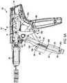
- FIG. 5Ais a perspective, partially transparent view of a surgical clip applier having an overload member that includes a biasing element housed within the trigger and an overload linkage operatively coupling the biasing element to a pivot linkage, showing the trigger and the overload member in unactuated positions;
- FIG. 5Bis a perspective, partially transparent view of the surgical clip applier in FIG. 5A , showing the trigger in an actuated position and the overload member in a first position without the biasing element being compressed;
- FIG. 5Cis a perspective, partially transparent view of the surgical clip applier in FIG. 5A , showing the trigger in an actuated position and the overload member in a second position in which the biasing element is compressed;
- FIG. 6Ais a perspective, partially transparent view of a proximal portion of the surgical clip applier in FIG. 5A ;
- FIG. 6Bis a perspective, partially transparent view of the proximal portion of the surgical clip applier in FIG. 5B ;
- FIG. 6Cis a perspective, partially transparent view of the proximal portion of the surgical clip applier in FIG. 5C ;
- FIG. 7Ais a perspective, partially transparent view of a proximal portion of a surgical clip applier having an overload member that includes a biasing element disposed within an overload linkage, showing the trigger and the overload member in unactuated positions;
- FIG. 7Bis a perspective, partially transparent view of the proximal portion of the surgical clip applier in FIG. 7A , showing the trigger in an actuated position and the overload member in a first position without the biasing element being compressed;
- FIG. 7Cis a perspective, partially transparent view of the proximal portion of the surgical clip applier in FIG. 7A , showing the trigger in an actuated position and the overload member in a second position in which the biasing element is compressed;
- FIG. 8is side, partially transparent view of another embodiment of a pivot linkage and an overload member operably coupled to one another, with the overload member including a biasing element coupled to a trigger;
- FIG. 9is side, partially transparent view of a pivot linkage and an overload member having a biasing element coupled to the pivot linkage and a trigger, in accordance with another embodiment
- FIG. 10is side, partially transparent view of another embodiment of a pivot linkage and an overload member that includes a biasing element coupled to the pivot linkage and a trigger;
- FIG. 11Ais a perspective, partially transparent view of a proximal portion of another embodiment of a surgical clip applier that includes a pivot linkage and an overload member that includes an overload linkage and a biasing element that is a deflectable region of the pivot linkage, showing the trigger and the overload member in unactuated positions;
- FIG. 11Bis a perspective, partially transparent view of the proximal portion of the surgical clip applier in FIG. 11A , showing the trigger in an actuated position and the overload member in a first position without the biasing element being deformed;
- FIG. 11Cis a perspective, partially transparent view of the proximal portion of the surgical clip applier in FIG. 11A , showing the trigger in an actuated position and the overload member in a second position in which the biasing element is deformed;
- FIG. 12Ais a perspective view of an embodiment of an overload mechanism when the closing force has not yet exceeded the predetermined threshold force
- FIG. 12Bis a perspective view of the overload mechanism in FIG. 12A when the closing force has exceeded the predetermined threshold force
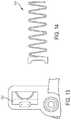
- FIG. 13is a side view of another embodiment of an overload mechanism when the closing force has not yet exceeded the predetermined threshold force
- FIG. 14is a side view of an embodiment of a biasing element
- FIG. 15Ais a perspective view of an overload mechanism when the closing force has not yet exceeded the predetermined threshold force according to another embodiment.
- FIG. 15Bis another perspective view of the overload mechanism in FIG. 15A .
- like-named components of the embodimentsgenerally have similar features, and thus within a particular embodiment each feature of each like-named component is not necessarily fully elaborated upon.
- linear or circular dimensionsare used in the description of the disclosed systems, devices, and methods, such dimensions are not intended to limit the types of shapes that can be used in conjunction with such systems, devices, and methods.
- a person skilled in the artwill recognize that an equivalent to such linear and circular dimensions can easily be determined for any geometric shape. Sizes and shapes of the systems and devices, and the components thereof, can depend at least on the anatomy of the subject in which the systems and devices will be used, the size and shape of components with which the systems and devices will be used, and the methods and procedures in which the systems and devices will be used.
- proximal and distalare used herein with reference to a user, such as a clinician, gripping a handle of an instrument.
- Other spatial termssuch as “front” and “rear” similarly correspond respectively to distal and proximal.
- spatial termssuch as “vertical” and “horizontal” are used herein with respect to the drawings. However, surgical instruments are used in many orientations and positions, and these spatial terms are not intended to be limiting and absolute.
- Surgical devices and methodsare provided for preventing an overload force from transferring to an end-effector on the surgical device when the force exceeds a predetermined threshold force.
- a surgical devicehaving a handle housing and an elongate shaft extending distally therefrom with an end effector coupled to a distal end.
- a triggeris coupled to the handle housing and movable between an unactuated position and an actuated position for causing corresponding movement of the end effector.
- the devicecan further include an overload mechanism that prevents an excessive closure force from being applied to the end effector when resistance is encountered.
- the overload mechanismcan allow the trigger to continue to move toward the actuated position without causing further closing of the opposed jaws.
- An exemplary surgical clip appliercan include a variety of features to facilitate application of a surgical clip, as described herein and illustrated in the drawings. However, a person skilled in the art will appreciate that the surgical clip applier can include only some of these features and/or it can include a variety of other features known in the art.
- the surgical clip appliers described hereinare merely intended to represent certain exemplary embodiments. Moreover, while the overload mechanisms are described in connection with surgical clip appliers, the overload mechanisms can be used in connection with any type of surgical device.
- FIGS. 1-4Billustrate one embodiment of a conventional surgical clip applier 100 .
- the surgical clip applier 100generally includes a housing 102 having a stationary handle 104 and a movable handle or trigger 106 that is pivotally coupled to the housing 102 .
- An elongate shaft 108extends distally from the housing 102 and includes a jaw assembly 110 formed on a distal end 108 d thereof and including first and second jaws 112 , 114 that are movable between open and closed positions.
- the first and second jaws 112 , 114include opposed inward facing surfaces and each inward facing surface has a clip track formed therealong for receiving and guiding legs of a clip into the first and second jaws 112 , 114 .
- the elongate shaft 108can be rotated with respect to the housing 102 via a rotation knob 103 .
- the elongate shaft 108can include an outer support tube 120 , an upper shroud 122 coupled distally to the outer support tube 120 , and a lower shroud 124 .
- the outer support tube 120 and the upper and lower shrouds 122 , 124form an outer casing of the shaft 108 .
- a clip stack 126 including multiple surgical clipsis disposed within a clip track or holder 128 of the shaft 108 proximal to the first and second jaws 112 , 114 , and is biased distally.
- a floor 130extends beneath the clip stack 126 for maintaining the clip stack 126 in alignment within the shaft 108 , and for guiding a distal-most clip 126 d into the jaws 112 , 114 .
- a lifter spring 132is positioned just proximal to the jaws 112 , 114 and distal to the clip stack 126 for preventing distal movement of the clip stack 126 , with the distal-most clip 126 d disposed around the lifter spring 132 .
- a feeder bar 134extends through the elongate shaft 108 for feeding the distal-most clip 126 d into the jaws. As shown in FIG.
- a former tube 136extends around a proximal end of the jaws 112 , 114 and is movable distally to cam the jaws 112 , 114 to a closed position for forming a clip 127 disposed therebetween.
- the surgical clip applier 100has a clip forming assembly including various components that operate together to close the jaws 112 , 114 when the trigger 106 is activated to thereby cause a clip (e.g., clip 127 ) disposed in the jaws to be applied (formed) to the tissue.
- the clip forming assemblyencompasses the former tube 136 and other components that are coupled to the trigger 106 configured to be activated to move the former tube 136 distally to thereby close the jaws 112 , 114 .
- a clip advancing assembly of the surgical clip applier 100includes the feeder bar 134 that is also coupled to the trigger 106 , via a link 107 extending proximally from the trigger 106 , as shown in FIGS. 4A and 4B . In this way, when the trigger 106 is activated, the feeder bar 134 is caused to move proximally, opposite to a distal direction in which the former tube 136 is moved upon activation of the trigger 106 .
- the clip forming and clip advancing assembliescan have any suitable configurations.
- the former tube 136 of the clip forming assemblyis coupled, via an inner coupling 138 , to a former plate 140 in the housing 102 that is, in turn, coupled to the trigger 106 via a pin 141
- the feeder bar 134 of the clip advancing assemblyis coupled to the trigger 106 via a feeder plate 142 that is also coupled to the trigger 106 , via the link 107 .
- FIG. 4A and 4Bthe former tube 136 of the clip forming assembly is coupled, via an inner coupling 138 , to a former plate 140 in the housing 102 that is, in turn, coupled to the trigger 106 via a pin 141
- the feeder bar 134 of the clip advancing assemblyis coupled to the trigger 106 via a feeder plate 142 that is also coupled to the trigger 106 , via the link 107 .
- the feeder plate 142has arms 144 a , 144 b at a distal end thereof that are disposed over and mate with a proximal end of an outer coupling 146 (shown partially transparent).
- a connecting pin 148 at a distal end of the outer coupling 146attaches the feeder bar 134 to the outer coupling 146 .
- FIGS. 4A and 4Billustrate the housing 102 with part of an outer casing removed, and FIG. 4B shows the housing 102 without the feeder plate 142 , for illustration purposes only. It should be appreciated that the surgical clip applier 100 can include various other components and assemblies that are not described herein for the sake of simplicity.
- the former plate 140 of the clip forming assemblyis advanced distally to cause the former tube 136 to advance distally over the jaws 112 , 114 , thereby camming the jaws 112 , 114 to the closed position.
- the feeder plate 142 of the clip advancing assemblyis moved proximally, thereby pulling the feeder bar 134 proximally to position the feeder bar 134 proximal of the distal-most clip 126 d of the clip stack 126 .
- FIG. 2shows the clip 127 in an original, pre-formed configuration.
- the proximal movement of the clip forming assemblycauses the former tube 136 to retract relative to the jaws, thus allowing the jaws 112 , 114 to move to the original open position, thereby releasing the formed clip.
- the distal movement of the clip advancing assemblycauses the feeder bar 134 to move distally, and the feeder bar 134 thereby pushes the distal-most clip 126 d distally, overcoming the biasing force of the lifter spring 132 and causing the lifter spring 132 to deflect out of the way, thereby allowing the distal-most clip 126 d to be advanced into the jaws 112 , 114 .
- the distal-most clipbecomes positioned in the jaws' clip tracks, like the clip 127 in FIG. 3 .
- the floor 130helps guide the distal-most clip into the clip tracks of the jaws 112 , 114 .
- overload mechanismsare shown and described below, the overload mechanisms disclosed herein can be coupled to other actuation mechanisms, and need not be coupled to a trigger as described.
- the clip appliercan be powered and the overload mechanism can be coupled to an actuation button for actuating a motor to control firing of the device.
- the overload mechanismcan be configured to couple to a robotic system, such that actuation of the device is controlled through the robotic system.
- a closing forceis applied to move the trigger 106 from an unactuated position to an actuated position, thereby advancing a distal-most clip 126 d into the jaws 112 , 114 .
- the closing force required to continue closing the jaws 112 , 114 around the clip 127can significantly increase when, for example, the clip 127 is formed about thick and/or incompressible tissue, formed about a previous formed clip about the tissue of interest, and/or formed about other hard objects located about the tissue of interest.
- An increase in the closing forcecan result in overload on the jaws 112 , 114 .
- a reaction force from the former tube 136can be encountered.
- a usertypically applies excessive closing force to the trigger 106 to overcome this reaction force and to complete the closing stroke (i.e., moving the trigger 106 to the actuated position).
- Thiscan cause the former tube 136 to unduly force the jaws 112 , 114 closed, which can result in deformation of the jaws 112 , 114 and/or damage to other components of the surgical clip applier 100 .
- This deformation of the jaws 112 , 114can cause improper formation of formed clips and/or premature release of preformed or partially formed clips and/or damage to tissue positioned between the jaws 112 , 114 .
- an overload mechanismfor limiting a maximum force applied to the jaw assembly 110 of the surgical clip applier 100 to avoid overload on the jaws 112 , 114 .
- the overload mechanisms provided hereinare designed and positioned between the trigger 106 (or other actuation mechanisms) and the clip forming assembly such that when the closing force exceeds a predetermined threshold, the closing force is transferred to the overload mechanism instead of the clip forming assembly, thereby preventing the jaws 112 , 114 from being improperly forced closed.
- these overload mechanismscan be designed having a similar path of movement of a conventional trigger, and therefore incorporation of the overload mechanisms described herein into conventional surgical clip appliers, like surgical clip applier 100 in FIGS. 1-4B , would not necessarily require changes, let alone substantial changes, to other internal mechanisms of the surgical clip appliers.
- FIGS. 5A-5Cillustrate an exemplary embodiment of a surgical clip applier 200 that includes an overload mechanism.
- FIG. 6A-6Cillustrates proximal view of the surgical clip applier 200 .
- the surgical clip applier 200can be similar to the surgical clip applier 100 ( FIGS. 1-4B ) and is therefore not described in detail herein.
- the overload mechanismincludes a pivot linkage 250 and an overload member 252 that are coupled to one another and located between the trigger 206 and the clip forming assembly, specifically the former tube 236 and the former plate 240 of the clip forming assembly, resulting in an indirect coupling between the trigger 206 from the clip forming assembly.
- the trigger 206When the trigger 206 is actuated, it pivots about a trigger pin 254 , which defines the trigger pivot axis (T a ), from an unactuated position ( FIGS. 5A and 6A ) to an actuated position ( FIGS. 5B and 6B ). This movement transfers a closing force from the trigger 206 through the overload member 252 to the pivot linkage 250 , and consequently, to the clip forming assembly.
- a trigger pin 254which defines the trigger pivot axis (T a )
- This movementtransfers a closing force from the trigger 206 through the overload member 252 to the pivot linkage 250 , and consequently, to the clip forming assembly.
- the closing forceis transferred from the trigger 206 to the overload member 252 and thereafter to the pivot linkage 250 such that the pivot linkage 250 engages the clip forming assembly and causes the clip forming assembly to distally advance and move the jaws 212 , 214 from an open position to a closed position.
- the pivot linkage 250can be coupled between the clip forming assembly and the overload member 252 .
- the pivot linkage 250can be somewhat V-shaped with a first end 256 a coupled to the former plate 240 of the clip forming assembly via a dowel pin 241 and a second end 256 b coupled to the overload member 252 at a pivot joint 256 .
- the trigger 206is actuated and pivots, along with the pivot linkage 250 , about the trigger pin 254 to cause distal advancement of the clip forming assembly, as long as the force required to actuate the trigger 206 and close the jaws does not exceed the predetermined threshold force.
- the pivotal movement of the pivot linkage 250will thus distally advance the former plate 240 , and consequently the former tube 236 , to cause the pair of jaws 212 , 214 to move from the open position to the close position.
- the former tube 236 and the former plate 242 of the clip forming assemblywill exert a counter force (reaction force) against the first end 256 a of the pivot linkage 250 which will prevent the pivot linkage 250 from moving to its distal-most position, thereby preventing the jaws from fully closing.
- the trigger 206is not yet at its actuated position. In order for the trigger 206 to reach its actuated position when an overload is encountered, an excessive closing force can be applied to the trigger 206 . To avoid this excessive force from being transferred to the clip forming assembly, the pivot linkage 250 can remain stationary relative to the handle housing 202 .
- the overload member 252can be coupled between the second end 256 b of the pivot linkage 250 and the trigger 206 . While the overload member 252 can have a variety of configurations, the overload member 252 shown in FIGS. 5A-6C includes an overload linkage 258 and a biasing element 260 . As shown in FIGS. 5A-6C , the overload linkage 258 has first and second ends 258 a , 258 b . The first end 258 a is coupled to the second end 256 b of the pivot linkage 250 at engagement pivot joint 256 , and the second end 258 b of the overload linkage 258 is slidably coupled to the trigger 206 via a movable pin 264 .
- the movable pin 264moves relative to the trigger 206 and can be housed in a slot 266 formed in the trigger 206 .
- the slot 266can extend completely through the wall of the trigger 206 such that movement of the movable pin 264 from a proximal end 266 p to a distal end 266 d of the slot 266 can be observed by a user.
- the overload linkage 258is also operably connected to the biasing element 260 , for example, a spring or other spring-like member, which is housed within the trigger 206 .
- the biasing element 260can have a variety of configuration, in one exemplary embodiment as shown in FIGS. 5A-6C , the biasing element 260 can be in the form of a helical spring that is housed within the trigger 206 and that has an end 260 a that is coupled to the trigger 206 at an engagement point 268 .
- the biasing element 260can be initially precompressed to a first compressed state (CO to bias the overload linkage 258 to a first position when the trigger 206 pivots about the trigger pin 254 , which defines the trigger pivot axis (T a ), from the unactuated to the actuated position until an overload is encountered.
- COfirst compressed state
- the trigger 206is in its fully actuated position and the biasing element 260 remains in the first compressed state (CO such that the movable pin 264 remains at the proximal end 266 p of the slot 266 . That is, the second end 258 b of the overload linkage 258 has not yet slid distally within the trigger 206 .
- the closing forcecan overcome the biasing force of the biasing element 260 to allow the overload linkage 258 to move from the first position to a second position, thereby preventing further movement of the pivot linkage 250 relative to the handle housing 202 .
- the overload linkage 258slides within the trigger 206 and compresses the biasing element 260 to a second compressed state (C 2 ).
- the overload linkage 258transfers the excess closing force to the biasing element 260 by moving the movable pin 264 toward the distal end 266 d of the slot 266 causing the biasing element 260 to compress. This allows the overload linkage 258 to move in a manner that prevents transfer of the closing force, when it exceeds the predetermined threshold force, to the pivot linkage 250 such that the pivot linkage 250 , and consequently the clip forming assembly, can remain stationary.
- the predetermined threshold forcecan correspond to a force required to overcome the biasing force of the biasing element 260 , and thus a biasing element 260 having a desired biasing force can be selected during manufacturing as required based on the particular configuration of the device and the forces required to close the jaws without causing damage to the jaws.
- FIGS. 7A-7Cillustrate another exemplary embodiment of an overload member disposed within a surgical clip applier 300 that is similar to surgical clip applier 100 ( FIGS. 1-4B ).
- the overload member 352includes an overload linkage 358 having housing 370 that is coupled to the trigger 306 at an engagement point 368 and a pusher 372 , e.g., a piston or piston-like member, that is coupled to the pivot linkage 350 at engagement point 356 and to the housing 370 .
- the overload member 352also includes a biasing element 360 that is positioned about the outer surface of the overload linkage 358 .
- the biasing element 360can bias the overload linkage 358 to a first position when the trigger 306 pivots about the trigger pin 354 , which defines the trigger pivot axis (T a ), from the unactuated to the actuated position until an overload is encountered. For example, as shown in FIG. 7B , where no overload is encountered during the closing stroke of the trigger 306 , the trigger 306 is in its fully actuated position and the biasing element 360 remains in an uncompressed state (C 1 ).
- the pusher 372slides distally within the housing 370 , thereby compressing the biasing element 360 to a compressed state (C 2 ), thereby resulting in a decrease of the overall length of the overload member 352 from a first length (L 1 ) to a second length (L 2 ).
- the compression of the biasing element 360prevents further movement of the pivot linkage 350 relative to the handle housing 302 .
- the excessive closing forceis transferred through the overload linkage 358 to the biasing element 360 , rather than the clip forming assembly, thereby preventing the clip forming assembly from unduly forcing the jaws closed.
- the predetermined threshold forcecan correspond to the force required to overcome the biasing force of the biasing element 360 , and may be selected as desired during manufacturing.
- FIGS. 5A-7Cillustrate overload members having an overload linkage 258 , 358 and a biasing element 260 , 360 , in the form of a helical spring
- the overload membercan have other configurations, such as those shown in FIGS. 8-10 .
- FIGS. 8-10each illustrate an overload member that is in the form of a leaf spring 576 , 676 , 776 .
- the leaf spring 576which is illustrated as having an arc-shaped length, has a first end 576 a coupled to a first end 506 a of the trigger 506 and a second end 576 b slidably disposed within the trigger adjacent to a second end 506 b of the trigger 506 .
- the arced mid-portion of the leaf spring 576is in operable contact with the pivot linkage 550 such that the leaf spring 576 applies a biasing force to the pivot linkage 550 .
- the closing forceexceeds a predetermined threshold force
- the continued movement of the trigger 506 to its actuated positiontransfers the closing force to the leaf spring 576 .
- the leaf spring 576compresses by flexing, causing its second end 576 b to slide distally toward the second end 506 b of the trigger 506 , and thus, elongate and expand within the trigger 506 , as shown.
- no further movement of the pivot linkage 550occurs relative to the handle housing.
- the first end 676 a of the leaf spring 676is coupled to a pivot linkage 650 and a second end 676 b is coupled to an end 606 b of the trigger 606 .
- the leaf spring 676 in this embodimenthas a linear resting configuration in which a biasing force is applied to the pivot linkage 650 .
- the closing forceexceeds a predetermined threshold force
- the continued movement of the trigger 606 to its actuated positiontransfers the closing force to the leaf spring 676 causing the leaf spring 676 to deform by bending in a direction (D) toward the trigger 606 .
- the pivot linkage 650can remain stationary relative to the handle housing.
- the leaf spring 776has a first end 776 a coupled to the pivot linkage 750 and a second end 776 b coupled to an end 706 b of the trigger 706 .
- the leaf spring 776has two opposing U-shaped segments formed therein and biased to a spaced configuration in which a biasing force is applied to the pivot linkage 750 .
- the closing forceexceeds a predetermined threshold force
- the continued movement of the trigger 706 to its actuated positiontransfers the closing force to the leaf spring 776 .
- the leaf spring 776compresses whereby the U-shaped segments collapse toward one another, so as to prevent further movement of the pivot linkage 750 relative to the handle housing.
- FIGS. 11A-11Cillustrates another exemplary embodiment of an overload mechanism disposed within a surgical clip applier 800 that is similar to the surgical clip applier 100 ( FIGS. 1-4B ).
- the overload mechanismincludes a pivot linkage 850 having first and second portions 850 a , 850 b and an overload member 852 .
- the overload member 852has an overload linkage 858 and a biasing element 860 .
- the biasing element 860is a deflectable region 878 of the second portion 850 b of the pivot linkage 850 .
- the biasing elementcan be a leaf spring.
- the biasing element 860can bias the overload linkage 858 to a first position when the trigger 806 pivots about the trigger pivot axis from the unactuated to the actuated position until the closing force exceeds the predetermined threshold force. If no overload is encountered, the overload mechanism is not engaged, as illustrated in FIG. 11B . However, when an overload is encountered, as shown in FIG. 11C , the closing force overcomes the biasing force of the biasing element 860 to allow the overload member 852 to move to a second position so to prevent further movement of the pivot linkage 850 relative to the handle housing 802 . More specifically, as shown in FIG.
- the biasing element 860deforms or deflects so that the first portion 850 a of the pivot linkage 850 , and thus the clip forming assembly, remain stationary while the trigger 806 continues to move to its actuated position.
- the first portion 850 a of the pivot linkage 850can be less flexible than the second portion 850 b of the pivot linkage 850 .
- the first portionis formed of a first material that has a first modulus of elasticity value and the second portion is formed of a second material that has a second modulus of elasticity that is less than the first modulus of elasticity value.
- the second portioncan be structured in a manner than allows the second portion to deflect or deform when excessive closing force is applied.
- the second portioncan have a narrower width than the first portion.
- the second portioncan have a non-solid cross section with either singular or repeating beam/rib elements, whereas the first portion can be solid or constructed of thicker beam/rib elements.
- FIGS. 12A-12Billustrates another exemplary embodiment of an overload mechanism.
- the overload mechanismincludes a biasing element 960 disposed within a dowel pin slot 980 of the trigger 906 .
- the biasing element 960can have a variety of configurations, the biasing in FIGS. 12A-12B is a spring in an accordion configuration.
- the biasing element 1060can be a leaf spring, or as shown in FIG. 14 , the biasing element 1160 can be a planar spring in a zig-zag configuration.
- a dowel pin 941which connects the trigger 906 to the clip forming assembly, is also disposed within the dowel pin slot 980 .
- the dowel pin 941is located between a distal end 980 d of the slot 980 and the biasing element 960 so that, during use, the dowel pin 941 is in operably contact with the biasing element 960 .
- the closing forceexceeds the predetermined threshold force during the trigger's closing stroke, the closing force overcomes the biasing force of the biasing element 960 causing the dowel pin 941 to move toward a proximal end 980 p of the dowel pin slot 980 , thereby compressing the biasing element 960 ( FIG. 12B ).
- the trigger 906can continue to move to its actuated position without causing any further distal advancement of the clip forming assembly.
- FIGS. 15A-15Billustrate another exemplary embodiment of an overload mechanism.
- the trigger 1406includes two dowel pin slots 1480 a , 1480 b each having two biasing elements 1482 , 1484 .
- the first biasing element 1482includes two coil springs 1482 a , 1482 b that are adjacent to one another.
- the second biasing element 1484includes two coil springs 1484 a , 1484 b that are adjacent to each other.
- a dowel pin 1441which connects the trigger 1406 to the clip forming assembly, is also disposed within the dowel pin slots 1480 a , 1480 b .
- the dowel pin 1441is located between the distal end 1480 d of each slot 1480 a 1480 b and corresponding biasing element 1482 , 1484 so that the dowel pin 1441 is operably connected to each biasing element 1482 , 1484 .
- each biasing element 1482 , 1484biases the dowel pin 1441 against the distal end 1480 d of each corresponding slot 1480 until the closing force exceeds the predetermined threshold force.
- the closing forceexceeds the predetermined threshold force, the closing force is transferred to the overload mechanism, causing the dowel pin 1441 to move toward the proximal end 1480 p of each dowel pin slot 1480 a , 1480 b , thereby compressing the corresponding biasing elements 1482 , 1484 .
- the compression of the biasing elements 1482 , 1484allow the trigger 1406 to continue to move to its actuated position without causing any further distal advancement of the clip forming assembly.
- surgical clip applierscan be used to form a clip about a surgical site, such as a vessel, duct, shunt, etc. Any suitable method can be used for operating any surgical device described herein.
- the pair of jawse.g., jaws 112 , 114 shown in FIGS. 1-3 , can be manipulated to position tissue therebetween.
- the trigger 206 (or other actuation device) of the surgical clip applier 200can be actuated to transfer a force from the trigger 206 through the overload member 252 to the pivot linkage 250 to actuate the clip forming assembly, which in turn, moves the pair of jaws from an open position to a closed position.
- a clipe.g., clip 127 shown in FIGS. 2-3
- the jawscan be deformed such that the clip engages the tissue positioned between the jaws.
- the overload member 252can move relative to the handle housing 202 to prevent the force from being transferred to at least a portion of the pivot linkage 250 , and consequently the clip forming assembly. That is, if the force exceeds the predetermined threshold force, the overload member 252 can cause the pivot linkage 250 to remain stationary to thereby prevent further distal advancement of the clip forming assembly, and consequently, prevent the excessive closing force from causing undesirable damage to the tissue and/or the surgical device.
- a predetermined threshold forcei.e., a force corresponding to a force required to overcome the biasing force of the biasing element
- the devices disclosed hereincan be designed to be disposed of after a single use, or they can be designed to be used multiple times. In either case, however, the device can be reconditioned for reuse after at least one use. Reconditioning can include any combination of the steps of disassembly of the device, followed by cleaning or replacement of particular pieces and subsequent reassembly. In particular, the device can be disassembled, and any number of the particular pieces or parts of the device can be selectively replaced or removed in any combination. Upon cleaning and/or replacement of particular parts, the device can be reassembled for subsequent use either at a reconditioning facility, or by a surgical team immediately prior to a surgical procedure.
- reconditioning of a devicecan utilize a variety of techniques for disassembly, cleaning/replacement, and reassembly. Use of such techniques, and the resulting reconditioned device, are all within the scope of the present application.
Landscapes
- Health & Medical Sciences (AREA)
- Surgery (AREA)
- Life Sciences & Earth Sciences (AREA)
- Heart & Thoracic Surgery (AREA)
- Molecular Biology (AREA)
- Veterinary Medicine (AREA)
- Engineering & Computer Science (AREA)
- Biomedical Technology (AREA)
- Public Health (AREA)
- Medical Informatics (AREA)
- Nuclear Medicine, Radiotherapy & Molecular Imaging (AREA)
- Animal Behavior & Ethology (AREA)
- General Health & Medical Sciences (AREA)
- Oral & Maxillofacial Surgery (AREA)
- Pathology (AREA)
- Reproductive Health (AREA)
- Vascular Medicine (AREA)
- Surgical Instruments (AREA)
Abstract
Description
Claims (15)
Priority Applications (7)
| Application Number | Priority Date | Filing Date | Title |
|---|---|---|---|
| US15/674,096US10751052B2 (en) | 2017-08-10 | 2017-08-10 | Surgical device with overload mechanism |
| CN201880065922.7ACN111200978B (en) | 2017-08-10 | 2018-08-07 | Surgical device with overload mechanism |
| BR112020002513-5ABR112020002513B1 (en) | 2017-08-10 | 2018-08-07 | SURGICAL DEVICE WITH OVERLOAD MECHANISM |
| MX2020001560AMX2020001560A (en) | 2017-08-10 | 2018-08-07 | Surgical device with overload mechanism. |
| PCT/IB2018/055951WO2019030676A1 (en) | 2017-08-10 | 2018-08-07 | Surgical device with overload mechanism |
| JP2020507044AJP7275105B2 (en) | 2017-08-10 | 2018-08-07 | Surgical device with overload mechanism |
| EP18188266.3AEP3441018B1 (en) | 2017-08-10 | 2018-08-09 | Surgical device with overload mechanism |
Applications Claiming Priority (1)
| Application Number | Priority Date | Filing Date | Title |
|---|---|---|---|
| US15/674,096US10751052B2 (en) | 2017-08-10 | 2017-08-10 | Surgical device with overload mechanism |
Publications (2)
| Publication Number | Publication Date |
|---|---|
| US20190046196A1 US20190046196A1 (en) | 2019-02-14 |
| US10751052B2true US10751052B2 (en) | 2020-08-25 |
Family
ID=64958549
Family Applications (1)
| Application Number | Title | Priority Date | Filing Date |
|---|---|---|---|
| US15/674,096Active2038-04-27US10751052B2 (en) | 2017-08-10 | 2017-08-10 | Surgical device with overload mechanism |
Country Status (6)
| Country | Link |
|---|---|
| US (1) | US10751052B2 (en) |
| EP (1) | EP3441018B1 (en) |
| JP (1) | JP7275105B2 (en) |
| CN (1) | CN111200978B (en) |
| MX (1) | MX2020001560A (en) |
| WO (1) | WO2019030676A1 (en) |
Cited By (119)
| Publication number | Priority date | Publication date | Assignee | Title |
|---|---|---|---|---|
| US11013563B2 (en) | 2017-12-28 | 2021-05-25 | Ethicon Llc | Drive arrangements for robot-assisted surgical platforms |
| US11026713B2 (en) | 2017-10-30 | 2021-06-08 | Cilag Gmbh International | Surgical clip applier configured to store clips in a stored state |
| US11026751B2 (en) | 2017-12-28 | 2021-06-08 | Cilag Gmbh International | Display of alignment of staple cartridge to prior linear staple line |
| US11045591B2 (en) | 2017-12-28 | 2021-06-29 | Cilag Gmbh International | Dual in-series large and small droplet filters |
| US11056244B2 (en) | 2017-12-28 | 2021-07-06 | Cilag Gmbh International | Automated data scaling, alignment, and organizing based on predefined parameters within surgical networks |
| US11051876B2 (en) | 2017-12-28 | 2021-07-06 | Cilag Gmbh International | Surgical evacuation flow paths |
| US11058498B2 (en) | 2017-12-28 | 2021-07-13 | Cilag Gmbh International | Cooperative surgical actions for robot-assisted surgical platforms |
| US11076921B2 (en) | 2017-12-28 | 2021-08-03 | Cilag Gmbh International | Adaptive control program updates for surgical hubs |
| US11090047B2 (en) | 2018-03-28 | 2021-08-17 | Cilag Gmbh International | Surgical instrument comprising an adaptive control system |
| US11096693B2 (en) | 2017-12-28 | 2021-08-24 | Cilag Gmbh International | Adjustment of staple height of at least one row of staples based on the sensed tissue thickness or force in closing |
| US11100631B2 (en) | 2017-12-28 | 2021-08-24 | Cilag Gmbh International | Use of laser light and red-green-blue coloration to determine properties of back scattered light |
| US11096688B2 (en) | 2018-03-28 | 2021-08-24 | Cilag Gmbh International | Rotary driven firing members with different anvil and channel engagement features |
| US11114195B2 (en) | 2017-12-28 | 2021-09-07 | Cilag Gmbh International | Surgical instrument with a tissue marking assembly |
| US11123070B2 (en) | 2017-10-30 | 2021-09-21 | Cilag Gmbh International | Clip applier comprising a rotatable clip magazine |
| US11132462B2 (en) | 2017-12-28 | 2021-09-28 | Cilag Gmbh International | Data stripping method to interrogate patient records and create anonymized record |
| US11147607B2 (en) | 2017-12-28 | 2021-10-19 | Cilag Gmbh International | Bipolar combination device that automatically adjusts pressure based on energy modality |
| US11160605B2 (en) | 2017-12-28 | 2021-11-02 | Cilag Gmbh International | Surgical evacuation sensing and motor control |
| US11166772B2 (en) | 2017-12-28 | 2021-11-09 | Cilag Gmbh International | Surgical hub coordination of control and communication of operating room devices |
| US11166716B2 (en) | 2018-03-28 | 2021-11-09 | Cilag Gmbh International | Stapling instrument comprising a deactivatable lockout |
| US11179208B2 (en) | 2017-12-28 | 2021-11-23 | Cilag Gmbh International | Cloud-based medical analytics for security and authentication trends and reactive measures |
| US11179175B2 (en) | 2017-12-28 | 2021-11-23 | Cilag Gmbh International | Controlling an ultrasonic surgical instrument according to tissue location |
| US11179204B2 (en) | 2017-12-28 | 2021-11-23 | Cilag Gmbh International | Wireless pairing of a surgical device with another device within a sterile surgical field based on the usage and situational awareness of devices |
| US11202570B2 (en) | 2017-12-28 | 2021-12-21 | Cilag Gmbh International | Communication hub and storage device for storing parameters and status of a surgical device to be shared with cloud based analytics systems |
| US11207067B2 (en) | 2018-03-28 | 2021-12-28 | Cilag Gmbh International | Surgical stapling device with separate rotary driven closure and firing systems and firing member that engages both jaws while firing |
| US11219453B2 (en) | 2018-03-28 | 2022-01-11 | Cilag Gmbh International | Surgical stapling devices with cartridge compatible closure and firing lockout arrangements |
| US11229436B2 (en) | 2017-10-30 | 2022-01-25 | Cilag Gmbh International | Surgical system comprising a surgical tool and a surgical hub |
| US11234756B2 (en) | 2017-12-28 | 2022-02-01 | Cilag Gmbh International | Powered surgical tool with predefined adjustable control algorithm for controlling end effector parameter |
| US11253315B2 (en) | 2017-12-28 | 2022-02-22 | Cilag Gmbh International | Increasing radio frequency to create pad-less monopolar loop |
| US11257589B2 (en) | 2017-12-28 | 2022-02-22 | Cilag Gmbh International | Real-time analysis of comprehensive cost of all instrumentation used in surgery utilizing data fluidity to track instruments through stocking and in-house processes |
| US11259806B2 (en) | 2018-03-28 | 2022-03-01 | Cilag Gmbh International | Surgical stapling devices with features for blocking advancement of a camming assembly of an incompatible cartridge installed therein |
| US11259830B2 (en) | 2018-03-08 | 2022-03-01 | Cilag Gmbh International | Methods for controlling temperature in ultrasonic device |
| US11259807B2 (en) | 2019-02-19 | 2022-03-01 | Cilag Gmbh International | Staple cartridges with cam surfaces configured to engage primary and secondary portions of a lockout of a surgical stapling device |
| US11266468B2 (en) | 2017-12-28 | 2022-03-08 | Cilag Gmbh International | Cooperative utilization of data derived from secondary sources by intelligent surgical hubs |
| US11273001B2 (en) | 2017-12-28 | 2022-03-15 | Cilag Gmbh International | Surgical hub and modular device response adjustment based on situational awareness |
| US11278281B2 (en) | 2017-12-28 | 2022-03-22 | Cilag Gmbh International | Interactive surgical system |
| US11278280B2 (en) | 2018-03-28 | 2022-03-22 | Cilag Gmbh International | Surgical instrument comprising a jaw closure lockout |
| US11284936B2 (en) | 2017-12-28 | 2022-03-29 | Cilag Gmbh International | Surgical instrument having a flexible electrode |
| US11291510B2 (en) | 2017-10-30 | 2022-04-05 | Cilag Gmbh International | Method of hub communication with surgical instrument systems |
| US11291495B2 (en) | 2017-12-28 | 2022-04-05 | Cilag Gmbh International | Interruption of energy due to inadvertent capacitive coupling |
| US11298148B2 (en) | 2018-03-08 | 2022-04-12 | Cilag Gmbh International | Live time tissue classification using electrical parameters |
| US11304720B2 (en) | 2017-12-28 | 2022-04-19 | Cilag Gmbh International | Activation of energy devices |
| US11304745B2 (en) | 2017-12-28 | 2022-04-19 | Cilag Gmbh International | Surgical evacuation sensing and display |
| US11304763B2 (en) | 2017-12-28 | 2022-04-19 | Cilag Gmbh International | Image capturing of the areas outside the abdomen to improve placement and control of a surgical device in use |
| US11304699B2 (en) | 2017-12-28 | 2022-04-19 | Cilag Gmbh International | Method for adaptive control schemes for surgical network control and interaction |
| US11308075B2 (en) | 2017-12-28 | 2022-04-19 | Cilag Gmbh International | Surgical network, instrument, and cloud responses based on validation of received dataset and authentication of its source and integrity |
| US11311342B2 (en) | 2017-10-30 | 2022-04-26 | Cilag Gmbh International | Method for communicating with surgical instrument systems |
| US11311306B2 (en) | 2017-12-28 | 2022-04-26 | Cilag Gmbh International | Surgical systems for detecting end effector tissue distribution irregularities |
| US11317937B2 (en) | 2018-03-08 | 2022-05-03 | Cilag Gmbh International | Determining the state of an ultrasonic end effector |
| USD950728S1 (en) | 2019-06-25 | 2022-05-03 | Cilag Gmbh International | Surgical staple cartridge |
| US11317915B2 (en) | 2019-02-19 | 2022-05-03 | Cilag Gmbh International | Universal cartridge based key feature that unlocks multiple lockout arrangements in different surgical staplers |
| US11317919B2 (en) | 2017-10-30 | 2022-05-03 | Cilag Gmbh International | Clip applier comprising a clip crimping system |
| US11324557B2 (en) | 2017-12-28 | 2022-05-10 | Cilag Gmbh International | Surgical instrument with a sensing array |
| USD952144S1 (en) | 2019-06-25 | 2022-05-17 | Cilag Gmbh International | Surgical staple cartridge retainer with firing system authentication key |
| US11337746B2 (en) | 2018-03-08 | 2022-05-24 | Cilag Gmbh International | Smart blade and power pulsing |
| US11357503B2 (en) | 2019-02-19 | 2022-06-14 | Cilag Gmbh International | Staple cartridge retainers with frangible retention features and methods of using same |
| US11364075B2 (en) | 2017-12-28 | 2022-06-21 | Cilag Gmbh International | Radio frequency energy device for delivering combined electrical signals |
| US11369377B2 (en) | 2019-02-19 | 2022-06-28 | Cilag Gmbh International | Surgical stapling assembly with cartridge based retainer configured to unlock a firing lockout |
| US11376002B2 (en) | 2017-12-28 | 2022-07-05 | Cilag Gmbh International | Surgical instrument cartridge sensor assemblies |
| US11389164B2 (en) | 2017-12-28 | 2022-07-19 | Cilag Gmbh International | Method of using reinforced flexible circuits with multiple sensors to optimize performance of radio frequency devices |
| US11410259B2 (en) | 2017-12-28 | 2022-08-09 | Cilag Gmbh International | Adaptive control program updates for surgical devices |
| US11423007B2 (en) | 2017-12-28 | 2022-08-23 | Cilag Gmbh International | Adjustment of device control programs based on stratified contextual data in addition to the data |
| US11424027B2 (en) | 2017-12-28 | 2022-08-23 | Cilag Gmbh International | Method for operating surgical instrument systems |
| US11419667B2 (en) | 2017-12-28 | 2022-08-23 | Cilag Gmbh International | Ultrasonic energy device which varies pressure applied by clamp arm to provide threshold control pressure at a cut progression location |
| US11419630B2 (en) | 2017-12-28 | 2022-08-23 | Cilag Gmbh International | Surgical system distributed processing |
| US11432885B2 (en) | 2017-12-28 | 2022-09-06 | Cilag Gmbh International | Sensing arrangements for robot-assisted surgical platforms |
| US11446052B2 (en) | 2017-12-28 | 2022-09-20 | Cilag Gmbh International | Variation of radio frequency and ultrasonic power level in cooperation with varying clamp arm pressure to achieve predefined heat flux or power applied to tissue |
| USD964564S1 (en) | 2019-06-25 | 2022-09-20 | Cilag Gmbh International | Surgical staple cartridge retainer with a closure system authentication key |
| US11464535B2 (en) | 2017-12-28 | 2022-10-11 | Cilag Gmbh International | Detection of end effector emersion in liquid |
| US11464511B2 (en) | 2019-02-19 | 2022-10-11 | Cilag Gmbh International | Surgical staple cartridges with movable authentication key arrangements |
| US11464559B2 (en) | 2017-12-28 | 2022-10-11 | Cilag Gmbh International | Estimating state of ultrasonic end effector and control system therefor |
| US11471156B2 (en) | 2018-03-28 | 2022-10-18 | Cilag Gmbh International | Surgical stapling devices with improved rotary driven closure systems |
| US11504192B2 (en) | 2014-10-30 | 2022-11-22 | Cilag Gmbh International | Method of hub communication with surgical instrument systems |
| US11510741B2 (en) | 2017-10-30 | 2022-11-29 | Cilag Gmbh International | Method for producing a surgical instrument comprising a smart electrical system |
| US11529187B2 (en) | 2017-12-28 | 2022-12-20 | Cilag Gmbh International | Surgical evacuation sensor arrangements |
| US11540855B2 (en) | 2017-12-28 | 2023-01-03 | Cilag Gmbh International | Controlling activation of an ultrasonic surgical instrument according to the presence of tissue |
| US11559307B2 (en) | 2017-12-28 | 2023-01-24 | Cilag Gmbh International | Method of robotic hub communication, detection, and control |
| US11559308B2 (en) | 2017-12-28 | 2023-01-24 | Cilag Gmbh International | Method for smart energy device infrastructure |
| US11564756B2 (en) | 2017-10-30 | 2023-01-31 | Cilag Gmbh International | Method of hub communication with surgical instrument systems |
| US11571234B2 (en) | 2017-12-28 | 2023-02-07 | Cilag Gmbh International | Temperature control of ultrasonic end effector and control system therefor |
| US11576677B2 (en) | 2017-12-28 | 2023-02-14 | Cilag Gmbh International | Method of hub communication, processing, display, and cloud analytics |
| US11589932B2 (en) | 2017-12-28 | 2023-02-28 | Cilag Gmbh International | Usage and technique analysis of surgeon / staff performance against a baseline to optimize device utilization and performance for both current and future procedures |
| US11589888B2 (en) | 2017-12-28 | 2023-02-28 | Cilag Gmbh International | Method for controlling smart energy devices |
| US11601371B2 (en) | 2017-12-28 | 2023-03-07 | Cilag Gmbh International | Surgical network determination of prioritization of communication, interaction, or processing based on system or device needs |
| US11596291B2 (en) | 2017-12-28 | 2023-03-07 | Cilag Gmbh International | Method of compressing tissue within a stapling device and simultaneously displaying of the location of the tissue within the jaws |
| US11602393B2 (en) | 2017-12-28 | 2023-03-14 | Cilag Gmbh International | Surgical evacuation sensing and generator control |
| US11612444B2 (en) | 2017-12-28 | 2023-03-28 | Cilag Gmbh International | Adjustment of a surgical device function based on situational awareness |
| US11659023B2 (en) | 2017-12-28 | 2023-05-23 | Cilag Gmbh International | Method of hub communication |
| US11666331B2 (en) | 2017-12-28 | 2023-06-06 | Cilag Gmbh International | Systems for detecting proximity of surgical end effector to cancerous tissue |
| US11696760B2 (en) | 2017-12-28 | 2023-07-11 | Cilag Gmbh International | Safety systems for smart powered surgical stapling |
| US11744604B2 (en) | 2017-12-28 | 2023-09-05 | Cilag Gmbh International | Surgical instrument with a hardware-only control circuit |
| US11771487B2 (en) | 2017-12-28 | 2023-10-03 | Cilag Gmbh International | Mechanisms for controlling different electromechanical systems of an electrosurgical instrument |
| US11786251B2 (en) | 2017-12-28 | 2023-10-17 | Cilag Gmbh International | Method for adaptive control schemes for surgical network control and interaction |
| US11786245B2 (en) | 2017-12-28 | 2023-10-17 | Cilag Gmbh International | Surgical systems with prioritized data transmission capabilities |
| US11801098B2 (en) | 2017-10-30 | 2023-10-31 | Cilag Gmbh International | Method of hub communication with surgical instrument systems |
| US11818052B2 (en) | 2017-12-28 | 2023-11-14 | Cilag Gmbh International | Surgical network determination of prioritization of communication, interaction, or processing based on system or device needs |
| US11832899B2 (en) | 2017-12-28 | 2023-12-05 | Cilag Gmbh International | Surgical systems with autonomously adjustable control programs |
| US11832840B2 (en) | 2017-12-28 | 2023-12-05 | Cilag Gmbh International | Surgical instrument having a flexible circuit |
| US11857152B2 (en) | 2017-12-28 | 2024-01-02 | Cilag Gmbh International | Surgical hub spatial awareness to determine devices in operating theater |
| US11864728B2 (en) | 2017-12-28 | 2024-01-09 | Cilag Gmbh International | Characterization of tissue irregularities through the use of mono-chromatic light refractivity |
| US11871901B2 (en) | 2012-05-20 | 2024-01-16 | Cilag Gmbh International | Method for situational awareness for surgical network or surgical network connected device capable of adjusting function based on a sensed situation or usage |
| US11896322B2 (en) | 2017-12-28 | 2024-02-13 | Cilag Gmbh International | Sensing the patient position and contact utilizing the mono-polar return pad electrode to provide situational awareness to the hub |
| US11896443B2 (en) | 2017-12-28 | 2024-02-13 | Cilag Gmbh International | Control of a surgical system through a surgical barrier |
| US11903587B2 (en) | 2017-12-28 | 2024-02-20 | Cilag Gmbh International | Adjustment to the surgical stapling control based on situational awareness |
| US11903601B2 (en) | 2017-12-28 | 2024-02-20 | Cilag Gmbh International | Surgical instrument comprising a plurality of drive systems |
| US11911045B2 (en) | 2017-10-30 | 2024-02-27 | Cllag GmbH International | Method for operating a powered articulating multi-clip applier |
| US11937769B2 (en) | 2017-12-28 | 2024-03-26 | Cilag Gmbh International | Method of hub communication, processing, storage and display |
| US11969216B2 (en) | 2017-12-28 | 2024-04-30 | Cilag Gmbh International | Surgical network recommendations from real time analysis of procedure variables against a baseline highlighting differences from the optimal solution |
| US11998193B2 (en) | 2017-12-28 | 2024-06-04 | Cilag Gmbh International | Method for usage of the shroud as an aspect of sensing or controlling a powered surgical device, and a control algorithm to adjust its default operation |
| US12029506B2 (en) | 2017-12-28 | 2024-07-09 | Cilag Gmbh International | Method of cloud based data analytics for use with the hub |
| US12035890B2 (en) | 2017-12-28 | 2024-07-16 | Cilag Gmbh International | Method of sensing particulate from smoke evacuated from a patient, adjusting the pump speed based on the sensed information, and communicating the functional parameters of the system to the hub |
| US12062442B2 (en) | 2017-12-28 | 2024-08-13 | Cilag Gmbh International | Method for operating surgical instrument systems |
| US12127729B2 (en) | 2017-12-28 | 2024-10-29 | Cilag Gmbh International | Method for smoke evacuation for surgical hub |
| US12133773B2 (en) | 2017-12-28 | 2024-11-05 | Cilag Gmbh International | Surgical hub and modular device response adjustment based on situational awareness |
| US12226151B2 (en) | 2017-12-28 | 2025-02-18 | Cilag Gmbh International | Capacitive coupled return path pad with separable array elements |
| US12303159B2 (en) | 2018-03-08 | 2025-05-20 | Cilag Gmbh International | Methods for estimating and controlling state of ultrasonic end effector |
| US12318152B2 (en) | 2017-12-28 | 2025-06-03 | Cilag Gmbh International | Computer implemented interactive surgical systems |
| US12376855B2 (en) | 2017-12-28 | 2025-08-05 | Cilag Gmbh International | Safety systems for smart powered surgical stapling |
| US12396806B2 (en) | 2017-12-28 | 2025-08-26 | Cilag Gmbh International | Adjustment of a surgical device function based on situational awareness |
| US12433508B2 (en) | 2017-12-28 | 2025-10-07 | Cilag Gmbh International | Surgical system having a surgical instrument controlled based on comparison of sensor and database data |
Families Citing this family (6)
| Publication number | Priority date | Publication date | Assignee | Title |
|---|---|---|---|---|
| US10617429B2 (en) | 2017-08-10 | 2020-04-14 | Ethicon Llc | Surgical clip applier |
| US10835260B2 (en)* | 2017-09-13 | 2020-11-17 | Covidien Lp | Endoscopic surgical clip applier and handle assemblies for use therewith |
| US20220346816A1 (en)* | 2019-08-27 | 2022-11-03 | Conmed Corporation | Force limiting mechanism for surgical instruments |
| CN113662607B (en)* | 2021-09-26 | 2022-07-05 | 苏州法兰克曼医疗器械有限公司 | Electric anastomat overload protection structure and electric anastomat |
| CN116035658B (en)* | 2023-03-06 | 2023-07-21 | 以诺康医疗科技(苏州)有限公司 | Combined clamping drive mechanism and surgical instrument |
| DE102023122449A1 (en)* | 2023-08-22 | 2025-02-27 | Aesculap Ag | Surgical pistol grip and surgical instrument with pistol grip |
Citations (8)
| Publication number | Priority date | Publication date | Assignee | Title |
|---|---|---|---|---|
| US5009661A (en)* | 1989-04-24 | 1991-04-23 | Michelson Gary K | Protective mechanism for surgical rongeurs |
| US5947984A (en)* | 1997-10-10 | 1999-09-07 | Ethicon Endo-Surger, Inc. | Ultrasonic clamp coagulator apparatus having force limiting clamping mechanism |
| EP1908426A1 (en) | 2006-10-05 | 2008-04-09 | Tyco Healthcare Group Lp | Method and force-limiting handle mechanism for a surgical instrument |
| US20080255608A1 (en) | 2007-04-16 | 2008-10-16 | Hinman Cameron D | Tool with end effector force limiter |
| US20110022052A1 (en)* | 2009-07-22 | 2011-01-27 | OrthoDynamix, LLC | Method and Devices for Force-Limiting Trigger Mechanism |
| US9011484B2 (en) | 2012-02-11 | 2015-04-21 | Karl Storz Gmbh & Co. Kg | Medical instrument |
| WO2016057281A1 (en) | 2014-10-10 | 2016-04-14 | Ethicon Endo-Surgery, Inc. | Surgical device with overload mechanism |
| US20170172608A1 (en) | 2015-12-21 | 2017-06-22 | Ethicon Endo-Surgery, Llc | Surgical instrument with variable clamping force |
Family Cites Families (4)
| Publication number | Priority date | Publication date | Assignee | Title |
|---|---|---|---|---|
| US7288098B2 (en)* | 2005-04-14 | 2007-10-30 | Ethicon Endo-Surgery, Inc. | Force limiting mechanism for medical instrument |
| US8939974B2 (en)* | 2009-10-09 | 2015-01-27 | Ethicon Endo-Surgery, Inc. | Surgical instrument comprising first and second drive systems actuatable by a common trigger mechanism |
| BR112015021082B1 (en)* | 2013-03-01 | 2022-05-10 | Ethicon Endo-Surgery, Inc | surgical instrument |
| US10092310B2 (en)* | 2014-03-27 | 2018-10-09 | Ethicon Llc | Electrosurgical devices |
- 2017
- 2017-08-10USUS15/674,096patent/US10751052B2/enactiveActive
- 2018
- 2018-08-07MXMX2020001560Apatent/MX2020001560A/enunknown
- 2018-08-07WOPCT/IB2018/055951patent/WO2019030676A1/ennot_activeCeased
- 2018-08-07JPJP2020507044Apatent/JP7275105B2/enactiveActive
- 2018-08-07CNCN201880065922.7Apatent/CN111200978B/enactiveActive
- 2018-08-09EPEP18188266.3Apatent/EP3441018B1/enactiveActive
Patent Citations (9)
| Publication number | Priority date | Publication date | Assignee | Title |
|---|---|---|---|---|
| US5009661A (en)* | 1989-04-24 | 1991-04-23 | Michelson Gary K | Protective mechanism for surgical rongeurs |
| US5947984A (en)* | 1997-10-10 | 1999-09-07 | Ethicon Endo-Surger, Inc. | Ultrasonic clamp coagulator apparatus having force limiting clamping mechanism |
| EP1908426A1 (en) | 2006-10-05 | 2008-04-09 | Tyco Healthcare Group Lp | Method and force-limiting handle mechanism for a surgical instrument |
| US20080083813A1 (en)* | 2006-10-05 | 2008-04-10 | Michael Zemlok | Method and force-limiting handle mechanism for a surgical instrument |
| US20080255608A1 (en) | 2007-04-16 | 2008-10-16 | Hinman Cameron D | Tool with end effector force limiter |
| US20110022052A1 (en)* | 2009-07-22 | 2011-01-27 | OrthoDynamix, LLC | Method and Devices for Force-Limiting Trigger Mechanism |
| US9011484B2 (en) | 2012-02-11 | 2015-04-21 | Karl Storz Gmbh & Co. Kg | Medical instrument |
| WO2016057281A1 (en) | 2014-10-10 | 2016-04-14 | Ethicon Endo-Surgery, Inc. | Surgical device with overload mechanism |
| US20170172608A1 (en) | 2015-12-21 | 2017-06-22 | Ethicon Endo-Surgery, Llc | Surgical instrument with variable clamping force |
Cited By (217)
| Publication number | Priority date | Publication date | Assignee | Title |
|---|---|---|---|---|
| US11871901B2 (en) | 2012-05-20 | 2024-01-16 | Cilag Gmbh International | Method for situational awareness for surgical network or surgical network connected device capable of adjusting function based on a sensed situation or usage |
| US11504192B2 (en) | 2014-10-30 | 2022-11-22 | Cilag Gmbh International | Method of hub communication with surgical instrument systems |
| US11109878B2 (en) | 2017-10-30 | 2021-09-07 | Cilag Gmbh International | Surgical clip applier comprising an automatic clip feeding system |
| US11696778B2 (en) | 2017-10-30 | 2023-07-11 | Cilag Gmbh International | Surgical dissectors configured to apply mechanical and electrical energy |
| US12121255B2 (en) | 2017-10-30 | 2024-10-22 | Cilag Gmbh International | Electrical power output control based on mechanical forces |
| US12059218B2 (en) | 2017-10-30 | 2024-08-13 | Cilag Gmbh International | Method of hub communication with surgical instrument systems |
| US12035983B2 (en) | 2017-10-30 | 2024-07-16 | Cilag Gmbh International | Method for producing a surgical instrument comprising a smart electrical system |
| US11051836B2 (en) | 2017-10-30 | 2021-07-06 | Cilag Gmbh International | Surgical clip applier comprising an empty clip cartridge lockout |
| US11925373B2 (en) | 2017-10-30 | 2024-03-12 | Cilag Gmbh International | Surgical suturing instrument comprising a non-circular needle |
| US11071560B2 (en) | 2017-10-30 | 2021-07-27 | Cilag Gmbh International | Surgical clip applier comprising adaptive control in response to a strain gauge circuit |
| US11911045B2 (en) | 2017-10-30 | 2024-02-27 | Cllag GmbH International | Method for operating a powered articulating multi-clip applier |
| US11026712B2 (en) | 2017-10-30 | 2021-06-08 | Cilag Gmbh International | Surgical instruments comprising a shifting mechanism |
| US11819231B2 (en) | 2017-10-30 | 2023-11-21 | Cilag Gmbh International | Adaptive control programs for a surgical system comprising more than one type of cartridge |
| US11801098B2 (en) | 2017-10-30 | 2023-10-31 | Cilag Gmbh International | Method of hub communication with surgical instrument systems |
| US11793537B2 (en) | 2017-10-30 | 2023-10-24 | Cilag Gmbh International | Surgical instrument comprising an adaptive electrical system |
| US11103268B2 (en) | 2017-10-30 | 2021-08-31 | Cilag Gmbh International | Surgical clip applier comprising adaptive firing control |
| US11229436B2 (en) | 2017-10-30 | 2022-01-25 | Cilag Gmbh International | Surgical system comprising a surgical tool and a surgical hub |
| US11759224B2 (en) | 2017-10-30 | 2023-09-19 | Cilag Gmbh International | Surgical instrument systems comprising handle arrangements |
| US12329467B2 (en) | 2017-10-30 | 2025-06-17 | Cilag Gmbh International | Method of hub communication with surgical instrument systems |
| US11129636B2 (en) | 2017-10-30 | 2021-09-28 | Cilag Gmbh International | Surgical instruments comprising an articulation drive that provides for high articulation angles |
| US11123070B2 (en) | 2017-10-30 | 2021-09-21 | Cilag Gmbh International | Clip applier comprising a rotatable clip magazine |
| US11141160B2 (en) | 2017-10-30 | 2021-10-12 | Cilag Gmbh International | Clip applier comprising a motor controller |
| US11648022B2 (en) | 2017-10-30 | 2023-05-16 | Cilag Gmbh International | Surgical instrument systems comprising battery arrangements |
| US11602366B2 (en) | 2017-10-30 | 2023-03-14 | Cilag Gmbh International | Surgical suturing instrument configured to manipulate tissue using mechanical and electrical power |
| US11564703B2 (en) | 2017-10-30 | 2023-01-31 | Cilag Gmbh International | Surgical suturing instrument comprising a capture width which is larger than trocar diameter |
| US11564756B2 (en) | 2017-10-30 | 2023-01-31 | Cilag Gmbh International | Method of hub communication with surgical instrument systems |
| US11510741B2 (en) | 2017-10-30 | 2022-11-29 | Cilag Gmbh International | Method for producing a surgical instrument comprising a smart electrical system |
| US11026713B2 (en) | 2017-10-30 | 2021-06-08 | Cilag Gmbh International | Surgical clip applier configured to store clips in a stored state |
| US11413042B2 (en) | 2017-10-30 | 2022-08-16 | Cilag Gmbh International | Clip applier comprising a reciprocating clip advancing member |
| US11406390B2 (en) | 2017-10-30 | 2022-08-09 | Cilag Gmbh International | Clip applier comprising interchangeable clip reloads |
| US11317919B2 (en) | 2017-10-30 | 2022-05-03 | Cilag Gmbh International | Clip applier comprising a clip crimping system |
| US11311342B2 (en) | 2017-10-30 | 2022-04-26 | Cilag Gmbh International | Method for communicating with surgical instrument systems |
| US11207090B2 (en) | 2017-10-30 | 2021-12-28 | Cilag Gmbh International | Surgical instruments comprising a biased shifting mechanism |
| US11291465B2 (en) | 2017-10-30 | 2022-04-05 | Cilag Gmbh International | Surgical instruments comprising a lockable end effector socket |
| US11291510B2 (en) | 2017-10-30 | 2022-04-05 | Cilag Gmbh International | Method of hub communication with surgical instrument systems |
| US11896443B2 (en) | 2017-12-28 | 2024-02-13 | Cilag Gmbh International | Control of a surgical system through a surgical barrier |
| US12053159B2 (en) | 2017-12-28 | 2024-08-06 | Cilag Gmbh International | Method of sensing particulate from smoke evacuated from a patient, adjusting the pump speed based on the sensed information, and communicating the functional parameters of the system to the hub |
| US11234756B2 (en) | 2017-12-28 | 2022-02-01 | Cilag Gmbh International | Powered surgical tool with predefined adjustable control algorithm for controlling end effector parameter |
| US11253315B2 (en) | 2017-12-28 | 2022-02-22 | Cilag Gmbh International | Increasing radio frequency to create pad-less monopolar loop |
| US11257589B2 (en) | 2017-12-28 | 2022-02-22 | Cilag Gmbh International | Real-time analysis of comprehensive cost of all instrumentation used in surgery utilizing data fluidity to track instruments through stocking and in-house processes |
| US12433508B2 (en) | 2017-12-28 | 2025-10-07 | Cilag Gmbh International | Surgical system having a surgical instrument controlled based on comparison of sensor and database data |
| US12396806B2 (en) | 2017-12-28 | 2025-08-26 | Cilag Gmbh International | Adjustment of a surgical device function based on situational awareness |
| US12383115B2 (en) | 2017-12-28 | 2025-08-12 | Cilag Gmbh International | Method for smart energy device infrastructure |
| US11266468B2 (en) | 2017-12-28 | 2022-03-08 | Cilag Gmbh International | Cooperative utilization of data derived from secondary sources by intelligent surgical hubs |
| US12376855B2 (en) | 2017-12-28 | 2025-08-05 | Cilag Gmbh International | Safety systems for smart powered surgical stapling |
| US11273001B2 (en) | 2017-12-28 | 2022-03-15 | Cilag Gmbh International | Surgical hub and modular device response adjustment based on situational awareness |
| US11278281B2 (en) | 2017-12-28 | 2022-03-22 | Cilag Gmbh International | Interactive surgical system |
| US11026751B2 (en) | 2017-12-28 | 2021-06-08 | Cilag Gmbh International | Display of alignment of staple cartridge to prior linear staple line |
| US11284936B2 (en) | 2017-12-28 | 2022-03-29 | Cilag Gmbh International | Surgical instrument having a flexible electrode |
| US12318152B2 (en) | 2017-12-28 | 2025-06-03 | Cilag Gmbh International | Computer implemented interactive surgical systems |
| US12310586B2 (en) | 2017-12-28 | 2025-05-27 | Cilag Gmbh International | Method for adaptive control schemes for surgical network control and interaction |
| US12295674B2 (en) | 2017-12-28 | 2025-05-13 | Cilag Gmbh International | Usage and technique analysis of surgeon / staff performance against a baseline to optimize device utilization and performance for both current and future procedures |
| US11213359B2 (en) | 2017-12-28 | 2022-01-04 | Cilag Gmbh International | Controllers for robot-assisted surgical platforms |
| US11291495B2 (en) | 2017-12-28 | 2022-04-05 | Cilag Gmbh International | Interruption of energy due to inadvertent capacitive coupling |
| US12256995B2 (en) | 2017-12-28 | 2025-03-25 | Cilag Gmbh International | Surgical network recommendations from real time analysis of procedure variables against a baseline highlighting differences from the optimal solution |
| US12239320B2 (en) | 2017-12-28 | 2025-03-04 | Cilag Gmbh International | Method of using reinforced flexible circuits with multiple sensors to optimize performance of radio frequency devices |
| US12232729B2 (en) | 2017-12-28 | 2025-02-25 | Cilag Gmbh International | Systems for detecting proximity of surgical end effector to cancerous tissue |
| US11304720B2 (en) | 2017-12-28 | 2022-04-19 | Cilag Gmbh International | Activation of energy devices |
| US11304745B2 (en) | 2017-12-28 | 2022-04-19 | Cilag Gmbh International | Surgical evacuation sensing and display |
| US11304763B2 (en) | 2017-12-28 | 2022-04-19 | Cilag Gmbh International | Image capturing of the areas outside the abdomen to improve placement and control of a surgical device in use |
| US11304699B2 (en) | 2017-12-28 | 2022-04-19 | Cilag Gmbh International | Method for adaptive control schemes for surgical network control and interaction |
| US11308075B2 (en) | 2017-12-28 | 2022-04-19 | Cilag Gmbh International | Surgical network, instrument, and cloud responses based on validation of received dataset and authentication of its source and integrity |
| US12226166B2 (en) | 2017-12-28 | 2025-02-18 | Cilag Gmbh International | Surgical instrument with a sensing array |
| US11311306B2 (en) | 2017-12-28 | 2022-04-26 | Cilag Gmbh International | Surgical systems for detecting end effector tissue distribution irregularities |
| US12226151B2 (en) | 2017-12-28 | 2025-02-18 | Cilag Gmbh International | Capacitive coupled return path pad with separable array elements |
| US12207817B2 (en) | 2017-12-28 | 2025-01-28 | Cilag Gmbh International | Safety systems for smart powered surgical stapling |
| US12193766B2 (en) | 2017-12-28 | 2025-01-14 | Cilag Gmbh International | Situationally aware surgical system configured for use during a surgical procedure |
| US11202570B2 (en) | 2017-12-28 | 2021-12-21 | Cilag Gmbh International | Communication hub and storage device for storing parameters and status of a surgical device to be shared with cloud based analytics systems |
| US11324557B2 (en) | 2017-12-28 | 2022-05-10 | Cilag Gmbh International | Surgical instrument with a sensing array |
| US12193636B2 (en) | 2017-12-28 | 2025-01-14 | Cilag Gmbh International | Characterization of tissue irregularities through the use of mono-chromatic light refractivity |
| US12144518B2 (en) | 2017-12-28 | 2024-11-19 | Cilag Gmbh International | Surgical systems for detecting end effector tissue distribution irregularities |
| US12137991B2 (en) | 2017-12-28 | 2024-11-12 | Cilag Gmbh International | Display arrangements for robot-assisted surgical platforms |
| US12133660B2 (en) | 2017-12-28 | 2024-11-05 | Cilag Gmbh International | Controlling a temperature of an ultrasonic electromechanical blade according to frequency |
| US12133773B2 (en) | 2017-12-28 | 2024-11-05 | Cilag Gmbh International | Surgical hub and modular device response adjustment based on situational awareness |
| US12133709B2 (en) | 2017-12-28 | 2024-11-05 | Cilag Gmbh International | Communication hub and storage device for storing parameters and status of a surgical device to be shared with cloud based analytics systems |
| US11364075B2 (en) | 2017-12-28 | 2022-06-21 | Cilag Gmbh International | Radio frequency energy device for delivering combined electrical signals |
| US12127729B2 (en) | 2017-12-28 | 2024-10-29 | Cilag Gmbh International | Method for smoke evacuation for surgical hub |
| US11376002B2 (en) | 2017-12-28 | 2022-07-05 | Cilag Gmbh International | Surgical instrument cartridge sensor assemblies |
| US11382697B2 (en) | 2017-12-28 | 2022-07-12 | Cilag Gmbh International | Surgical instruments comprising button circuits |
| US11389164B2 (en) | 2017-12-28 | 2022-07-19 | Cilag Gmbh International | Method of using reinforced flexible circuits with multiple sensors to optimize performance of radio frequency devices |
| US11045591B2 (en) | 2017-12-28 | 2021-06-29 | Cilag Gmbh International | Dual in-series large and small droplet filters |
| US12096985B2 (en) | 2017-12-28 | 2024-09-24 | Cilag Gmbh International | Surgical network recommendations from real time analysis of procedure variables against a baseline highlighting differences from the optimal solution |
| US11410259B2 (en) | 2017-12-28 | 2022-08-09 | Cilag Gmbh International | Adaptive control program updates for surgical devices |
| US12096916B2 (en) | 2017-12-28 | 2024-09-24 | Cilag Gmbh International | Method of sensing particulate from smoke evacuated from a patient, adjusting the pump speed based on the sensed information, and communicating the functional parameters of the system to the hub |
| US12076010B2 (en) | 2017-12-28 | 2024-09-03 | Cilag Gmbh International | Surgical instrument cartridge sensor assemblies |
| US11179204B2 (en) | 2017-12-28 | 2021-11-23 | Cilag Gmbh International | Wireless pairing of a surgical device with another device within a sterile surgical field based on the usage and situational awareness of devices |
| US11423007B2 (en) | 2017-12-28 | 2022-08-23 | Cilag Gmbh International | Adjustment of device control programs based on stratified contextual data in addition to the data |
| US11424027B2 (en) | 2017-12-28 | 2022-08-23 | Cilag Gmbh International | Method for operating surgical instrument systems |
| US11419667B2 (en) | 2017-12-28 | 2022-08-23 | Cilag Gmbh International | Ultrasonic energy device which varies pressure applied by clamp arm to provide threshold control pressure at a cut progression location |
| US11419630B2 (en) | 2017-12-28 | 2022-08-23 | Cilag Gmbh International | Surgical system distributed processing |
| US11432885B2 (en) | 2017-12-28 | 2022-09-06 | Cilag Gmbh International | Sensing arrangements for robot-assisted surgical platforms |
| US11446052B2 (en) | 2017-12-28 | 2022-09-20 | Cilag Gmbh International | Variation of radio frequency and ultrasonic power level in cooperation with varying clamp arm pressure to achieve predefined heat flux or power applied to tissue |
| US12059169B2 (en) | 2017-12-28 | 2024-08-13 | Cilag Gmbh International | Controlling an ultrasonic surgical instrument according to tissue location |
| US12062442B2 (en) | 2017-12-28 | 2024-08-13 | Cilag Gmbh International | Method for operating surgical instrument systems |
| US11056244B2 (en) | 2017-12-28 | 2021-07-06 | Cilag Gmbh International | Automated data scaling, alignment, and organizing based on predefined parameters within surgical networks |
| US11464535B2 (en) | 2017-12-28 | 2022-10-11 | Cilag Gmbh International | Detection of end effector emersion in liquid |
| US12059124B2 (en) | 2017-12-28 | 2024-08-13 | Cilag Gmbh International | Surgical hub spatial awareness to determine devices in operating theater |
| US11464559B2 (en) | 2017-12-28 | 2022-10-11 | Cilag Gmbh International | Estimating state of ultrasonic end effector and control system therefor |
| US11013563B2 (en) | 2017-12-28 | 2021-05-25 | Ethicon Llc | Drive arrangements for robot-assisted surgical platforms |
| US11179175B2 (en) | 2017-12-28 | 2021-11-23 | Cilag Gmbh International | Controlling an ultrasonic surgical instrument according to tissue location |
| US11179208B2 (en) | 2017-12-28 | 2021-11-23 | Cilag Gmbh International | Cloud-based medical analytics for security and authentication trends and reactive measures |
| US12048496B2 (en) | 2017-12-28 | 2024-07-30 | Cilag Gmbh International | Adaptive control program updates for surgical hubs |
| US11529187B2 (en) | 2017-12-28 | 2022-12-20 | Cilag Gmbh International | Surgical evacuation sensor arrangements |
| US12042207B2 (en) | 2017-12-28 | 2024-07-23 | Cilag Gmbh International | Estimating state of ultrasonic end effector and control system therefor |
| US11540855B2 (en) | 2017-12-28 | 2023-01-03 | Cilag Gmbh International | Controlling activation of an ultrasonic surgical instrument according to the presence of tissue |
| US11559307B2 (en) | 2017-12-28 | 2023-01-24 | Cilag Gmbh International | Method of robotic hub communication, detection, and control |
| US11559308B2 (en) | 2017-12-28 | 2023-01-24 | Cilag Gmbh International | Method for smart energy device infrastructure |
| US11051876B2 (en) | 2017-12-28 | 2021-07-06 | Cilag Gmbh International | Surgical evacuation flow paths |
| US11166772B2 (en) | 2017-12-28 | 2021-11-09 | Cilag Gmbh International | Surgical hub coordination of control and communication of operating room devices |
| US11571234B2 (en) | 2017-12-28 | 2023-02-07 | Cilag Gmbh International | Temperature control of ultrasonic end effector and control system therefor |
| US11576677B2 (en) | 2017-12-28 | 2023-02-14 | Cilag Gmbh International | Method of hub communication, processing, display, and cloud analytics |
| US12035890B2 (en) | 2017-12-28 | 2024-07-16 | Cilag Gmbh International | Method of sensing particulate from smoke evacuated from a patient, adjusting the pump speed based on the sensed information, and communicating the functional parameters of the system to the hub |
| US11589932B2 (en) | 2017-12-28 | 2023-02-28 | Cilag Gmbh International | Usage and technique analysis of surgeon / staff performance against a baseline to optimize device utilization and performance for both current and future procedures |
| US11589888B2 (en) | 2017-12-28 | 2023-02-28 | Cilag Gmbh International | Method for controlling smart energy devices |
| US12029506B2 (en) | 2017-12-28 | 2024-07-09 | Cilag Gmbh International | Method of cloud based data analytics for use with the hub |
| US11601371B2 (en) | 2017-12-28 | 2023-03-07 | Cilag Gmbh International | Surgical network determination of prioritization of communication, interaction, or processing based on system or device needs |
| US11596291B2 (en) | 2017-12-28 | 2023-03-07 | Cilag Gmbh International | Method of compressing tissue within a stapling device and simultaneously displaying of the location of the tissue within the jaws |
| US11602393B2 (en) | 2017-12-28 | 2023-03-14 | Cilag Gmbh International | Surgical evacuation sensing and generator control |
| US11160605B2 (en) | 2017-12-28 | 2021-11-02 | Cilag Gmbh International | Surgical evacuation sensing and motor control |
| US11612408B2 (en) | 2017-12-28 | 2023-03-28 | Cilag Gmbh International | Determining tissue composition via an ultrasonic system |
| US11612444B2 (en) | 2017-12-28 | 2023-03-28 | Cilag Gmbh International | Adjustment of a surgical device function based on situational awareness |
| US12009095B2 (en) | 2017-12-28 | 2024-06-11 | Cilag Gmbh International | Real-time analysis of comprehensive cost of all instrumentation used in surgery utilizing data fluidity to track instruments through stocking and in-house processes |
| US11633237B2 (en) | 2017-12-28 | 2023-04-25 | Cilag Gmbh International | Usage and technique analysis of surgeon / staff performance against a baseline to optimize device utilization and performance for both current and future procedures |
| US11147607B2 (en) | 2017-12-28 | 2021-10-19 | Cilag Gmbh International | Bipolar combination device that automatically adjusts pressure based on energy modality |
| US11659023B2 (en) | 2017-12-28 | 2023-05-23 | Cilag Gmbh International | Method of hub communication |
| US11666331B2 (en) | 2017-12-28 | 2023-06-06 | Cilag Gmbh International | Systems for detecting proximity of surgical end effector to cancerous tissue |
| US11672605B2 (en) | 2017-12-28 | 2023-06-13 | Cilag Gmbh International | Sterile field interactive control displays |
| US11998193B2 (en) | 2017-12-28 | 2024-06-04 | Cilag Gmbh International | Method for usage of the shroud as an aspect of sensing or controlling a powered surgical device, and a control algorithm to adjust its default operation |
| US11969142B2 (en) | 2017-12-28 | 2024-04-30 | Cilag Gmbh International | Method of compressing tissue within a stapling device and simultaneously displaying the location of the tissue within the jaws |
| US11678881B2 (en) | 2017-12-28 | 2023-06-20 | Cilag Gmbh International | Spatial awareness of surgical hubs in operating rooms |
| US11132462B2 (en) | 2017-12-28 | 2021-09-28 | Cilag Gmbh International | Data stripping method to interrogate patient records and create anonymized record |
| US11696760B2 (en) | 2017-12-28 | 2023-07-11 | Cilag Gmbh International | Safety systems for smart powered surgical stapling |
| US11969216B2 (en) | 2017-12-28 | 2024-04-30 | Cilag Gmbh International | Surgical network recommendations from real time analysis of procedure variables against a baseline highlighting differences from the optimal solution |
| US11701185B2 (en) | 2017-12-28 | 2023-07-18 | Cilag Gmbh International | Wireless pairing of a surgical device with another device within a sterile surgical field based on the usage and situational awareness of devices |
| US11937769B2 (en) | 2017-12-28 | 2024-03-26 | Cilag Gmbh International | Method of hub communication, processing, storage and display |
| US11931110B2 (en) | 2017-12-28 | 2024-03-19 | Cilag Gmbh International | Surgical instrument comprising a control system that uses input from a strain gage circuit |
| US11712303B2 (en) | 2017-12-28 | 2023-08-01 | Cilag Gmbh International | Surgical instrument comprising a control circuit |
| US11737668B2 (en) | 2017-12-28 | 2023-08-29 | Cilag Gmbh International | Communication hub and storage device for storing parameters and status of a surgical device to be shared with cloud based analytics systems |
| US11744604B2 (en) | 2017-12-28 | 2023-09-05 | Cilag Gmbh International | Surgical instrument with a hardware-only control circuit |
| US11058498B2 (en) | 2017-12-28 | 2021-07-13 | Cilag Gmbh International | Cooperative surgical actions for robot-assisted surgical platforms |
| US11751958B2 (en) | 2017-12-28 | 2023-09-12 | Cilag Gmbh International | Surgical hub coordination of control and communication of operating room devices |
| US11114195B2 (en) | 2017-12-28 | 2021-09-07 | Cilag Gmbh International | Surgical instrument with a tissue marking assembly |
| US11775682B2 (en) | 2017-12-28 | 2023-10-03 | Cilag Gmbh International | Data stripping method to interrogate patient records and create anonymized record |
| US11771487B2 (en) | 2017-12-28 | 2023-10-03 | Cilag Gmbh International | Mechanisms for controlling different electromechanical systems of an electrosurgical instrument |
| US11779337B2 (en) | 2017-12-28 | 2023-10-10 | Cilag Gmbh International | Method of using reinforced flexible circuits with multiple sensors to optimize performance of radio frequency devices |
| US11786251B2 (en) | 2017-12-28 | 2023-10-17 | Cilag Gmbh International | Method for adaptive control schemes for surgical network control and interaction |
| US11786245B2 (en) | 2017-12-28 | 2023-10-17 | Cilag Gmbh International | Surgical systems with prioritized data transmission capabilities |
| US11918302B2 (en) | 2017-12-28 | 2024-03-05 | Cilag Gmbh International | Sterile field interactive control displays |
| US11100631B2 (en) | 2017-12-28 | 2021-08-24 | Cilag Gmbh International | Use of laser light and red-green-blue coloration to determine properties of back scattered light |
| US11818052B2 (en) | 2017-12-28 | 2023-11-14 | Cilag Gmbh International | Surgical network determination of prioritization of communication, interaction, or processing based on system or device needs |
| US11096693B2 (en) | 2017-12-28 | 2021-08-24 | Cilag Gmbh International | Adjustment of staple height of at least one row of staples based on the sensed tissue thickness or force in closing |
| US11832899B2 (en) | 2017-12-28 | 2023-12-05 | Cilag Gmbh International | Surgical systems with autonomously adjustable control programs |
| US11832840B2 (en) | 2017-12-28 | 2023-12-05 | Cilag Gmbh International | Surgical instrument having a flexible circuit |
| US11076921B2 (en) | 2017-12-28 | 2021-08-03 | Cilag Gmbh International | Adaptive control program updates for surgical hubs |
| US11844579B2 (en) | 2017-12-28 | 2023-12-19 | Cilag Gmbh International | Adjustments based on airborne particle properties |
| US11903601B2 (en) | 2017-12-28 | 2024-02-20 | Cilag Gmbh International | Surgical instrument comprising a plurality of drive systems |
| US11857152B2 (en) | 2017-12-28 | 2024-01-02 | Cilag Gmbh International | Surgical hub spatial awareness to determine devices in operating theater |
| US11864845B2 (en) | 2017-12-28 | 2024-01-09 | Cilag Gmbh International | Sterile field interactive control displays |
| US11864728B2 (en) | 2017-12-28 | 2024-01-09 | Cilag Gmbh International | Characterization of tissue irregularities through the use of mono-chromatic light refractivity |
| US11903587B2 (en) | 2017-12-28 | 2024-02-20 | Cilag Gmbh International | Adjustment to the surgical stapling control based on situational awareness |
| US11890065B2 (en) | 2017-12-28 | 2024-02-06 | Cilag Gmbh International | Surgical system to limit displacement |
| US11896322B2 (en) | 2017-12-28 | 2024-02-13 | Cilag Gmbh International | Sensing the patient position and contact utilizing the mono-polar return pad electrode to provide situational awareness to the hub |
| US11389188B2 (en) | 2018-03-08 | 2022-07-19 | Cilag Gmbh International | Start temperature of blade |
| US11464532B2 (en) | 2018-03-08 | 2022-10-11 | Cilag Gmbh International | Methods for estimating and controlling state of ultrasonic end effector |
| US11844545B2 (en) | 2018-03-08 | 2023-12-19 | Cilag Gmbh International | Calcified vessel identification |
| US11839396B2 (en) | 2018-03-08 | 2023-12-12 | Cilag Gmbh International | Fine dissection mode for tissue classification |
| US11259830B2 (en) | 2018-03-08 | 2022-03-01 | Cilag Gmbh International | Methods for controlling temperature in ultrasonic device |
| US12303159B2 (en) | 2018-03-08 | 2025-05-20 | Cilag Gmbh International | Methods for estimating and controlling state of ultrasonic end effector |
| US11298148B2 (en) | 2018-03-08 | 2022-04-12 | Cilag Gmbh International | Live time tissue classification using electrical parameters |
| US11707293B2 (en) | 2018-03-08 | 2023-07-25 | Cilag Gmbh International | Ultrasonic sealing algorithm with temperature control |
| US11317937B2 (en) | 2018-03-08 | 2022-05-03 | Cilag Gmbh International | Determining the state of an ultrasonic end effector |
| US11701162B2 (en) | 2018-03-08 | 2023-07-18 | Cilag Gmbh International | Smart blade application for reusable and disposable devices |
| US11337746B2 (en) | 2018-03-08 | 2022-05-24 | Cilag Gmbh International | Smart blade and power pulsing |
| US11701139B2 (en) | 2018-03-08 | 2023-07-18 | Cilag Gmbh International | Methods for controlling temperature in ultrasonic device |
| US11678927B2 (en) | 2018-03-08 | 2023-06-20 | Cilag Gmbh International | Detection of large vessels during parenchymal dissection using a smart blade |
| US11986233B2 (en) | 2018-03-08 | 2024-05-21 | Cilag Gmbh International | Adjustment of complex impedance to compensate for lost power in an articulating ultrasonic device |
| US11344326B2 (en) | 2018-03-08 | 2022-05-31 | Cilag Gmbh International | Smart blade technology to control blade instability |
| US11678901B2 (en) | 2018-03-08 | 2023-06-20 | Cilag Gmbh International | Vessel sensing for adaptive advanced hemostasis |
| US11617597B2 (en) | 2018-03-08 | 2023-04-04 | Cilag Gmbh International | Application of smart ultrasonic blade technology |
| US11589915B2 (en) | 2018-03-08 | 2023-02-28 | Cilag Gmbh International | In-the-jaw classifier based on a model |
| US12121256B2 (en) | 2018-03-08 | 2024-10-22 | Cilag Gmbh International | Methods for controlling temperature in ultrasonic device |
| US11399858B2 (en) | 2018-03-08 | 2022-08-02 | Cilag Gmbh International | Application of smart blade technology |
| US11534196B2 (en) | 2018-03-08 | 2022-12-27 | Cilag Gmbh International | Using spectroscopy to determine device use state in combo instrument |
| US11457944B2 (en) | 2018-03-08 | 2022-10-04 | Cilag Gmbh International | Adaptive advanced tissue treatment pad saver mode |
| US11406382B2 (en) | 2018-03-28 | 2022-08-09 | Cilag Gmbh International | Staple cartridge comprising a lockout key configured to lift a firing member |
| US11931027B2 (en) | 2018-03-28 | 2024-03-19 | Cilag Gmbh Interntional | Surgical instrument comprising an adaptive control system |
| US11471156B2 (en) | 2018-03-28 | 2022-10-18 | Cilag Gmbh International | Surgical stapling devices with improved rotary driven closure systems |
| US11259806B2 (en) | 2018-03-28 | 2022-03-01 | Cilag Gmbh International | Surgical stapling devices with features for blocking advancement of a camming assembly of an incompatible cartridge installed therein |
| US11096688B2 (en) | 2018-03-28 | 2021-08-24 | Cilag Gmbh International | Rotary driven firing members with different anvil and channel engagement features |
| US11197668B2 (en) | 2018-03-28 | 2021-12-14 | Cilag Gmbh International | Surgical stapling assembly comprising a lockout and an exterior access orifice to permit artificial unlocking of the lockout |
| US11090047B2 (en) | 2018-03-28 | 2021-08-17 | Cilag Gmbh International | Surgical instrument comprising an adaptive control system |
| US11166716B2 (en) | 2018-03-28 | 2021-11-09 | Cilag Gmbh International | Stapling instrument comprising a deactivatable lockout |
| US11219453B2 (en) | 2018-03-28 | 2022-01-11 | Cilag Gmbh International | Surgical stapling devices with cartridge compatible closure and firing lockout arrangements |
| US11589865B2 (en) | 2018-03-28 | 2023-02-28 | Cilag Gmbh International | Methods for controlling a powered surgical stapler that has separate rotary closure and firing systems |
| US11278280B2 (en) | 2018-03-28 | 2022-03-22 | Cilag Gmbh International | Surgical instrument comprising a jaw closure lockout |
| US11213294B2 (en) | 2018-03-28 | 2022-01-04 | Cilag Gmbh International | Surgical instrument comprising co-operating lockout features |
| US11986185B2 (en) | 2018-03-28 | 2024-05-21 | Cilag Gmbh International | Methods for controlling a surgical stapler |
| US11937817B2 (en) | 2018-03-28 | 2024-03-26 | Cilag Gmbh International | Surgical instruments with asymmetric jaw arrangements and separate closure and firing systems |
| US11207067B2 (en) | 2018-03-28 | 2021-12-28 | Cilag Gmbh International | Surgical stapling device with separate rotary driven closure and firing systems and firing member that engages both jaws while firing |
| US11317915B2 (en) | 2019-02-19 | 2022-05-03 | Cilag Gmbh International | Universal cartridge based key feature that unlocks multiple lockout arrangements in different surgical staplers |
| US11291445B2 (en) | 2019-02-19 | 2022-04-05 | Cilag Gmbh International | Surgical staple cartridges with integral authentication keys |
| US11464511B2 (en) | 2019-02-19 | 2022-10-11 | Cilag Gmbh International | Surgical staple cartridges with movable authentication key arrangements |
| US11517309B2 (en) | 2019-02-19 | 2022-12-06 | Cilag Gmbh International | Staple cartridge retainer with retractable authentication key |
| US11331101B2 (en) | 2019-02-19 | 2022-05-17 | Cilag Gmbh International | Deactivator element for defeating surgical stapling device lockouts |
| US11331100B2 (en) | 2019-02-19 | 2022-05-17 | Cilag Gmbh International | Staple cartridge retainer system with authentication keys |
| US11751872B2 (en) | 2019-02-19 | 2023-09-12 | Cilag Gmbh International | Insertable deactivator element for surgical stapler lockouts |
| US11298129B2 (en) | 2019-02-19 | 2022-04-12 | Cilag Gmbh International | Method for providing an authentication lockout in a surgical stapler with a replaceable cartridge |
| US11298130B2 (en) | 2019-02-19 | 2022-04-12 | Cilag Gmbh International | Staple cartridge retainer with frangible authentication key |
| US11259807B2 (en) | 2019-02-19 | 2022-03-01 | Cilag Gmbh International | Staple cartridges with cam surfaces configured to engage primary and secondary portions of a lockout of a surgical stapling device |
| US11925350B2 (en) | 2019-02-19 | 2024-03-12 | Cilag Gmbh International | Method for providing an authentication lockout in a surgical stapler with a replaceable cartridge |
| US11357503B2 (en) | 2019-02-19 | 2022-06-14 | Cilag Gmbh International | Staple cartridge retainers with frangible retention features and methods of using same |
| US11291444B2 (en) | 2019-02-19 | 2022-04-05 | Cilag Gmbh International | Surgical stapling assembly with cartridge based retainer configured to unlock a closure lockout |
| US11369377B2 (en) | 2019-02-19 | 2022-06-28 | Cilag Gmbh International | Surgical stapling assembly with cartridge based retainer configured to unlock a firing lockout |
| US11272931B2 (en) | 2019-02-19 | 2022-03-15 | Cilag Gmbh International | Dual cam cartridge based feature for unlocking a surgical stapler lockout |
| USD952144S1 (en) | 2019-06-25 | 2022-05-17 | Cilag Gmbh International | Surgical staple cartridge retainer with firing system authentication key |
| USD964564S1 (en) | 2019-06-25 | 2022-09-20 | Cilag Gmbh International | Surgical staple cartridge retainer with a closure system authentication key |
| USD950728S1 (en) | 2019-06-25 | 2022-05-03 | Cilag Gmbh International | Surgical staple cartridge |
Also Published As
| Publication number | Publication date |
|---|---|
| JP7275105B2 (en) | 2023-05-17 |
| WO2019030676A1 (en) | 2019-02-14 |
| JP2020529282A (en) | 2020-10-08 |
| BR112020002513A2 (en) | 2020-08-04 |
| CN111200978A (en) | 2020-05-26 |
| US20190046196A1 (en) | 2019-02-14 |
| EP3441018A1 (en) | 2019-02-13 |
| CN111200978B (en) | 2023-07-21 |
| EP3441018B1 (en) | 2021-06-30 |
| MX2020001560A (en) | 2020-08-17 |
Similar Documents
| Publication | Publication Date | Title |
|---|---|---|
| US10751052B2 (en) | Surgical device with overload mechanism | |
| KR101296695B1 (en) | Surgical clip advancement and alignment mechanism | |
| KR101196235B1 (en) | Force limiting mechanism for medical instrument | |
| US10022124B2 (en) | Articulation and firing force mechanisms | |
| KR101196234B1 (en) | Surgical clip applier methods | |
| EP2485659B1 (en) | Clip advancer with lockout mechanism | |
| KR101288789B1 (en) | Surgical clip applier ratchet mechanism | |
| KR101289628B1 (en) | Surgical clip advancement mechanism | |
| EP1764044B2 (en) | Clip applier with migrational resistance features | |
| EP1764043B1 (en) | Clip advancer mechanism with alignment features | |
| EP1764045B1 (en) | Clip applier configured to prevent clip fallout | |
| BR112020002513B1 (en) | SURGICAL DEVICE WITH OVERLOAD MECHANISM | |
| HK1100161B (en) | Clip advancer mechanism with alignment features |
Legal Events
| Date | Code | Title | Description |
|---|---|---|---|
| AS | Assignment | Owner name:ETHICON LLC, PUERTO RICO Free format text:ASSIGNMENT OF ASSIGNORS INTEREST;ASSIGNORS:STOKES, MICHAEL J.;BAXTER, CHESTER O., III;DEUPREE, DAVID A.;AND OTHERS;SIGNING DATES FROM 20170919 TO 20170927;REEL/FRAME:043943/0786 | |
| STPP | Information on status: patent application and granting procedure in general | Free format text:DOCKETED NEW CASE - READY FOR EXAMINATION | |
| STPP | Information on status: patent application and granting procedure in general | Free format text:NON FINAL ACTION MAILED | |
| STPP | Information on status: patent application and granting procedure in general | Free format text:NON FINAL ACTION MAILED | |
| STPP | Information on status: patent application and granting procedure in general | Free format text:RESPONSE TO NON-FINAL OFFICE ACTION ENTERED AND FORWARDED TO EXAMINER | |
| STPP | Information on status: patent application and granting procedure in general | Free format text:NON FINAL ACTION MAILED | |
| STPP | Information on status: patent application and granting procedure in general | Free format text:NOTICE OF ALLOWANCE MAILED -- APPLICATION RECEIVED IN OFFICE OF PUBLICATIONS | |
| STPP | Information on status: patent application and granting procedure in general | Free format text:PUBLICATIONS -- ISSUE FEE PAYMENT VERIFIED | |
| STCF | Information on status: patent grant | Free format text:PATENTED CASE | |
| AS | Assignment | Owner name:CILAG GMBH INTERNATIONAL, SWITZERLAND Free format text:ASSIGNMENT OF ASSIGNORS INTEREST;ASSIGNOR:ETHICON LLC;REEL/FRAME:056601/0339 Effective date:20210405 | |
| MAFP | Maintenance fee payment | Free format text:PAYMENT OF MAINTENANCE FEE, 4TH YEAR, LARGE ENTITY (ORIGINAL EVENT CODE: M1551); ENTITY STATUS OF PATENT OWNER: LARGE ENTITY Year of fee payment:4 |