US10750981B2 - System and method for health monitoring including a remote device - Google Patents
System and method for health monitoring including a remote deviceDownload PDFInfo
- Publication number
- US10750981B2 US10750981B2US15/400,916US201715400916AUS10750981B2US 10750981 B2US10750981 B2US 10750981B2US 201715400916 AUS201715400916 AUS 201715400916AUS 10750981 B2US10750981 B2US 10750981B2
- Authority
- US
- United States
- Prior art keywords
- biosensor
- value
- television
- blood flow
- spectral
- Prior art date
- Legal status (The legal status is an assumption and is not a legal conclusion. Google has not performed a legal analysis and makes no representation as to the accuracy of the status listed.)
- Active, expires
Links
Images


Classifications
- A—HUMAN NECESSITIES
- A61—MEDICAL OR VETERINARY SCIENCE; HYGIENE
- A61B—DIAGNOSIS; SURGERY; IDENTIFICATION
- A61B5/00—Measuring for diagnostic purposes; Identification of persons
- A61B5/145—Measuring characteristics of blood in vivo, e.g. gas concentration or pH-value ; Measuring characteristics of body fluids or tissues, e.g. interstitial fluid or cerebral tissue
- A61B5/14532—Measuring characteristics of blood in vivo, e.g. gas concentration or pH-value ; Measuring characteristics of body fluids or tissues, e.g. interstitial fluid or cerebral tissue for measuring glucose, e.g. by tissue impedance measurement
- A—HUMAN NECESSITIES
- A61—MEDICAL OR VETERINARY SCIENCE; HYGIENE
- A61B—DIAGNOSIS; SURGERY; IDENTIFICATION
- A61B5/00—Measuring for diagnostic purposes; Identification of persons
- A61B5/0002—Remote monitoring of patients using telemetry, e.g. transmission of vital signals via a communication network
- A61B5/0004—Remote monitoring of patients using telemetry, e.g. transmission of vital signals via a communication network characterised by the type of physiological signal transmitted
- A61B5/0008—Temperature signals
- A—HUMAN NECESSITIES
- A61—MEDICAL OR VETERINARY SCIENCE; HYGIENE
- A61B—DIAGNOSIS; SURGERY; IDENTIFICATION
- A61B5/00—Measuring for diagnostic purposes; Identification of persons
- A61B5/0002—Remote monitoring of patients using telemetry, e.g. transmission of vital signals via a communication network
- A61B5/0015—Remote monitoring of patients using telemetry, e.g. transmission of vital signals via a communication network characterised by features of the telemetry system
- A61B5/0022—Monitoring a patient using a global network, e.g. telephone networks, internet
- A—HUMAN NECESSITIES
- A61—MEDICAL OR VETERINARY SCIENCE; HYGIENE
- A61B—DIAGNOSIS; SURGERY; IDENTIFICATION
- A61B5/00—Measuring for diagnostic purposes; Identification of persons
- A61B5/02—Detecting, measuring or recording for evaluating the cardiovascular system, e.g. pulse, heart rate, blood pressure or blood flow
- A61B5/024—Measuring pulse rate or heart rate
- A61B5/02416—Measuring pulse rate or heart rate using photoplethysmograph signals, e.g. generated by infrared radiation
- A—HUMAN NECESSITIES
- A61—MEDICAL OR VETERINARY SCIENCE; HYGIENE
- A61B—DIAGNOSIS; SURGERY; IDENTIFICATION
- A61B5/00—Measuring for diagnostic purposes; Identification of persons
- A61B5/103—Measuring devices for testing the shape, pattern, colour, size or movement of the body or parts thereof, for diagnostic purposes
- A61B5/11—Measuring movement of the entire body or parts thereof, e.g. head or hand tremor or mobility of a limb
- A61B5/1118—Determining activity level
- A—HUMAN NECESSITIES
- A61—MEDICAL OR VETERINARY SCIENCE; HYGIENE
- A61B—DIAGNOSIS; SURGERY; IDENTIFICATION
- A61B5/00—Measuring for diagnostic purposes; Identification of persons
- A61B5/145—Measuring characteristics of blood in vivo, e.g. gas concentration or pH-value ; Measuring characteristics of body fluids or tissues, e.g. interstitial fluid or cerebral tissue
- A61B5/1455—Measuring characteristics of blood in vivo, e.g. gas concentration or pH-value ; Measuring characteristics of body fluids or tissues, e.g. interstitial fluid or cerebral tissue using optical sensors, e.g. spectral photometrical oximeters
- A61B5/14551—Measuring characteristics of blood in vivo, e.g. gas concentration or pH-value ; Measuring characteristics of body fluids or tissues, e.g. interstitial fluid or cerebral tissue using optical sensors, e.g. spectral photometrical oximeters for measuring blood gases
- A—HUMAN NECESSITIES
- A61—MEDICAL OR VETERINARY SCIENCE; HYGIENE
- A61B—DIAGNOSIS; SURGERY; IDENTIFICATION
- A61B5/00—Measuring for diagnostic purposes; Identification of persons
- A61B5/48—Other medical applications
- A61B5/4836—Diagnosis combined with treatment in closed-loop systems or methods
- A61B5/4839—Diagnosis combined with treatment in closed-loop systems or methods combined with drug delivery
- A—HUMAN NECESSITIES
- A61—MEDICAL OR VETERINARY SCIENCE; HYGIENE
- A61B—DIAGNOSIS; SURGERY; IDENTIFICATION
- A61B5/00—Measuring for diagnostic purposes; Identification of persons
- A61B5/68—Arrangements of detecting, measuring or recording means, e.g. sensors, in relation to patient
- A61B5/6801—Arrangements of detecting, measuring or recording means, e.g. sensors, in relation to patient specially adapted to be attached to or worn on the body surface
- A61B5/6813—Specially adapted to be attached to a specific body part
- A61B5/6814—Head
- A61B5/6815—Ear
- A61B5/6817—Ear canal
- A—HUMAN NECESSITIES
- A61—MEDICAL OR VETERINARY SCIENCE; HYGIENE
- A61B—DIAGNOSIS; SURGERY; IDENTIFICATION
- A61B5/00—Measuring for diagnostic purposes; Identification of persons
- A61B5/68—Arrangements of detecting, measuring or recording means, e.g. sensors, in relation to patient
- A61B5/6801—Arrangements of detecting, measuring or recording means, e.g. sensors, in relation to patient specially adapted to be attached to or worn on the body surface
- A61B5/6813—Specially adapted to be attached to a specific body part
- A61B5/6825—Hand
- A61B5/6826—Finger
- A—HUMAN NECESSITIES
- A61—MEDICAL OR VETERINARY SCIENCE; HYGIENE
- A61B—DIAGNOSIS; SURGERY; IDENTIFICATION
- A61B5/00—Measuring for diagnostic purposes; Identification of persons
- A61B5/74—Details of notification to user or communication with user or patient; User input means
- A61B5/742—Details of notification to user or communication with user or patient; User input means using visual displays
- A61B5/743—Displaying an image simultaneously with additional graphical information, e.g. symbols, charts, function plots
- A—HUMAN NECESSITIES
- A61—MEDICAL OR VETERINARY SCIENCE; HYGIENE
- A61M—DEVICES FOR INTRODUCING MEDIA INTO, OR ONTO, THE BODY; DEVICES FOR TRANSDUCING BODY MEDIA OR FOR TAKING MEDIA FROM THE BODY; DEVICES FOR PRODUCING OR ENDING SLEEP OR STUPOR
- A61M5/00—Devices for bringing media into the body in a subcutaneous, intra-vascular or intramuscular way; Accessories therefor, e.g. filling or cleaning devices, arm-rests
- A61M5/14—Infusion devices, e.g. infusing by gravity; Blood infusion; Accessories therefor
- A61M5/142—Pressure infusion, e.g. using pumps
- A61M5/14244—Pressure infusion, e.g. using pumps adapted to be carried by the patient, e.g. portable on the body
- A61M5/14248—Pressure infusion, e.g. using pumps adapted to be carried by the patient, e.g. portable on the body of the skin patch type
- A—HUMAN NECESSITIES
- A61—MEDICAL OR VETERINARY SCIENCE; HYGIENE
- A61M—DEVICES FOR INTRODUCING MEDIA INTO, OR ONTO, THE BODY; DEVICES FOR TRANSDUCING BODY MEDIA OR FOR TAKING MEDIA FROM THE BODY; DEVICES FOR PRODUCING OR ENDING SLEEP OR STUPOR
- A61M5/00—Devices for bringing media into the body in a subcutaneous, intra-vascular or intramuscular way; Accessories therefor, e.g. filling or cleaning devices, arm-rests
- A61M5/14—Infusion devices, e.g. infusing by gravity; Blood infusion; Accessories therefor
- A61M5/142—Pressure infusion, e.g. using pumps
- A61M5/145—Pressure infusion, e.g. using pumps using pressurised reservoirs, e.g. pressurised by means of pistons
- A61M5/1452—Pressure infusion, e.g. using pumps using pressurised reservoirs, e.g. pressurised by means of pistons pressurised by means of pistons
- A—HUMAN NECESSITIES
- A61—MEDICAL OR VETERINARY SCIENCE; HYGIENE
- A61M—DEVICES FOR INTRODUCING MEDIA INTO, OR ONTO, THE BODY; DEVICES FOR TRANSDUCING BODY MEDIA OR FOR TAKING MEDIA FROM THE BODY; DEVICES FOR PRODUCING OR ENDING SLEEP OR STUPOR
- A61M5/00—Devices for bringing media into the body in a subcutaneous, intra-vascular or intramuscular way; Accessories therefor, e.g. filling or cleaning devices, arm-rests
- A61M5/14—Infusion devices, e.g. infusing by gravity; Blood infusion; Accessories therefor
- A61M5/168—Means for controlling media flow to the body or for metering media to the body, e.g. drip meters, counters ; Monitoring media flow to the body
- A61M5/172—Means for controlling media flow to the body or for metering media to the body, e.g. drip meters, counters ; Monitoring media flow to the body electrical or electronic
- A61M5/1723—Means for controlling media flow to the body or for metering media to the body, e.g. drip meters, counters ; Monitoring media flow to the body electrical or electronic using feedback of body parameters, e.g. blood-sugar, pressure
- G06F19/00—
- G—PHYSICS
- G16—INFORMATION AND COMMUNICATION TECHNOLOGY [ICT] SPECIALLY ADAPTED FOR SPECIFIC APPLICATION FIELDS
- G16H—HEALTHCARE INFORMATICS, i.e. INFORMATION AND COMMUNICATION TECHNOLOGY [ICT] SPECIALLY ADAPTED FOR THE HANDLING OR PROCESSING OF MEDICAL OR HEALTHCARE DATA
- G16H40/00—ICT specially adapted for the management or administration of healthcare resources or facilities; ICT specially adapted for the management or operation of medical equipment or devices
- G16H40/60—ICT specially adapted for the management or administration of healthcare resources or facilities; ICT specially adapted for the management or operation of medical equipment or devices for the operation of medical equipment or devices
- G16H40/67—ICT specially adapted for the management or administration of healthcare resources or facilities; ICT specially adapted for the management or operation of medical equipment or devices for the operation of medical equipment or devices for remote operation
- A—HUMAN NECESSITIES
- A61—MEDICAL OR VETERINARY SCIENCE; HYGIENE
- A61B—DIAGNOSIS; SURGERY; IDENTIFICATION
- A61B2560/00—Constructional details of operational features of apparatus; Accessories for medical measuring apparatus
- A61B2560/02—Operational features
- A61B2560/0223—Operational features of calibration, e.g. protocols for calibrating sensors
- A—HUMAN NECESSITIES
- A61—MEDICAL OR VETERINARY SCIENCE; HYGIENE
- A61B—DIAGNOSIS; SURGERY; IDENTIFICATION
- A61B5/00—Measuring for diagnostic purposes; Identification of persons
- A61B5/0002—Remote monitoring of patients using telemetry, e.g. transmission of vital signals via a communication network
- A—HUMAN NECESSITIES
- A61—MEDICAL OR VETERINARY SCIENCE; HYGIENE
- A61M—DEVICES FOR INTRODUCING MEDIA INTO, OR ONTO, THE BODY; DEVICES FOR TRANSDUCING BODY MEDIA OR FOR TAKING MEDIA FROM THE BODY; DEVICES FOR PRODUCING OR ENDING SLEEP OR STUPOR
- A61M2205/00—General characteristics of the apparatus
- A61M2205/35—Communication
- A61M2205/3546—Range
- A61M2205/3553—Range remote, e.g. between patient's home and doctor's office
- A—HUMAN NECESSITIES
- A61—MEDICAL OR VETERINARY SCIENCE; HYGIENE
- A61M—DEVICES FOR INTRODUCING MEDIA INTO, OR ONTO, THE BODY; DEVICES FOR TRANSDUCING BODY MEDIA OR FOR TAKING MEDIA FROM THE BODY; DEVICES FOR PRODUCING OR ENDING SLEEP OR STUPOR
- A61M2205/00—General characteristics of the apparatus
- A61M2205/35—Communication
- A61M2205/3576—Communication with non implanted data transmission devices, e.g. using external transmitter or receiver
- A61M2205/3584—Communication with non implanted data transmission devices, e.g. using external transmitter or receiver using modem, internet or bluetooth
- A—HUMAN NECESSITIES
- A61—MEDICAL OR VETERINARY SCIENCE; HYGIENE
- A61M—DEVICES FOR INTRODUCING MEDIA INTO, OR ONTO, THE BODY; DEVICES FOR TRANSDUCING BODY MEDIA OR FOR TAKING MEDIA FROM THE BODY; DEVICES FOR PRODUCING OR ENDING SLEEP OR STUPOR
- A61M2230/00—Measuring parameters of the user
- A61M2230/04—Heartbeat characteristics, e.g. ECG, blood pressure modulation
- A61M2230/06—Heartbeat rate only
Definitions
- This applicationrelates to systems and methods of non-invasive, autonomous health monitoring and drug administration using a biosensor and remote device.
- biosensor measurementssuch as blood glucose levels in patients with diabetes.
- One techniquerequires a small blood sample from the patients, e.g. from a finger prick.
- the blood sampleis placed on a chemically prepared test strip and inserted into a glucose meter that analyzes the test strip and provides a blood glucose level.
- diabeticsmay need to prick their fingers multiple times within a day. This monitoring process can be painful, inconvenient and creates possible exposure to infections.
- measurements with these devicespresent an error of uncertainty range between approximately 10-20% depending on sample quality, human error, calibration, humidity, and hygiene in the sample area.
- biosensor measurementssuch as pulse, blood oxygen level, electrolyte levels, etc. It is important to provide a convenient system for monitoring and tracking these biosensor measurements.
- a remote deviceincludes a television control circuit configured to control a television in response to user input and a biosensor.
- the biosensorincludes a temperature sensor configured to obtain a temperature of a user, and a PPG circuit configured to emit light at a plurality of wavelengths directed at skin of the user and obtain a plurality of spectral responses at each of the plurality of wavelengths of light reflected from the skin.
- the processing circuitis configured to process the spectral responses at the plurality of wavelengths and determine biosensor data using the spectral responses, wherein the biosensor data includes oxygen saturation levels and concentration levels of one or more additional substances in arterial blood flow using the spectral responses.
- the remote devicefurther includes a wireless transceiver configured to transmit the temperature and biosensor data to the television.
- a remote deviceincludes a television control circuit configured to control a television in response to user input and a wireless transceiver configured to communicate with one or more external biosensors and a television.
- the remote devicefurther includes a processing circuit configured to receive biosensor data from the one or more external biosensors and transmit the biosensor data to the television for display.
- the televisionis configured to display the temperature and the biosensor data in one or more graphical user interfaces.
- the remote deviceis configured to generate a command to a drug administrative device to administer medicine.
- the remote deviceis configured to generate the command to the drug administration device to administer insulin in response to a blood glucose concentration level exceeding a predetermined threshold.
- the televisionincludes a wireless transceiver configured to communicate with a remote device, wherein the wireless transceiver receives biosensor data from the remote device and a processing device configured to generate a graphical user interface (GUI) that displays the biosensor data and transmit the biosensor data to a third party service provider.
- GUIgraphical user interface
- the biosensor dataincludes a heart rate and activity level.
- FIG. 1illustrates an exemplary embodiment of a remote device for health monitoring.
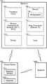
- FIG. 2illustrates a schematic block diagram of an exemplary embodiment of the remote device.
- FIG. 3illustrates an exemplary embodiment of a drug administrative device.
- FIG. 4illustrates a schematic block diagram of an embodiment of a syringe powered by a hydrogen fuel cell.
- FIG. 5illustrates an embodiment of a schematic block diagram of a wearable shirt button with an integrated button biosensor.
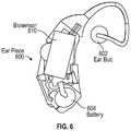
- FIG. 6illustrates illustrates an exemplary embodiment of another form factor of a biosensor.
- FIG. 7illustrates a schematic block diagram of an exemplary embodiment of a biosensor.
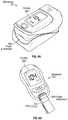
- FIG. 8Aillustrates an exemplary embodiment of another form factor of the biosensor.
- FIG. 8Billustrates an exemplary embodiment of another form factor of the biosensor.
- FIG. 9illustrates an embodiment of a graphical user interface (GUI) displayed on the television.
- GUIgraphical user interface
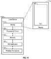
- FIG. 10illustrates an embodiment of a user device.
- FIG. 11illustrates a schematic block diagram of an embodiment of a graphical user interface (GUI) generated by the health monitoring application.
- GUIgraphical user interface
- FIG. 12illustrates a schematic block diagram of an embodiment of a graphical user interface (GUI) generated by the health monitoring application.
- GUIgraphical user interface
- FIG. 13illustrates a schematic block diagram of an embodiment of a graphical user interface (GUI) generated by the health monitoring application.
- GUIgraphical user interface
- FIG. 14Aillustrates a logical flow diagram of an embodiment of a method for the health monitoring application.
- FIG. 14Billustrates a logical flow diagram of an embodiment of a method for the health monitoring application.
- FIG. 15illustrates a schematic block diagram of an embodiment of an exemplary communication network in which the devices described herein may operate.
- FIG. 16illustrates a logic flow diagram of an exemplary embodiment of a method for analyzing content based on HM information.
- FIG. 17illustrates a schematic block diagram illustrating an embodiment of the PPG circuit in more detail.
- FIG. 18illustrates a schematic block diagram of another exemplary embodiment of the the PPG circuit.
- FIG. 19illustrates a schematic block diagram of an embodiment of the PPG circuit 224 with a plurality of photodetectors.
- FIG. 20illustrates a schematic diagram of a graph of actual clinical data obtained using PPG techniques at a plurality of wavelengths.
- FIG. 21illustrates a logical flow diagram of an embodiment of a method 2100 of the biosensor.
- FIG. 22illustrates a logical flow diagram of an embodiment of a method 2200 of determining concentration levels of one or more substances in more detail.
- FIG. 23Aillustrates a graph of an embodiment of an output of a broad spectrum light source.
- FIG. 23Billustrates a graph with an embodiment of an exemplary spectral response of detected light across a broad spectrum.
- FIG. 24illustrates a schematic block diagram of an embodiment of a method for determining concentration levels or indicators of substances in pulsating blood flow in more detail.
- FIG. 25illustrates a logical flow diagram of an exemplary method to determine an absorption coefficients ⁇ of a substance at a wavelength ⁇ .
- FIG. 26illustrates a schematic drawing of another exemplary embodiment of results of clinical data obtained using an embodiment of the biosensor from a second patient.
- FIG. 27illustrates a schematic drawing of another exemplary embodiment of results of clinical data obtained using an embodiment of the biosensor from a third patient.
- FIG. 28illustrates a schematic drawing of another exemplary embodiment of results of clinical data obtained using the biosensor from a fourth patient.
- FIG. 29illustrates an exemplary graph of spectral responses of a plurality of wavelengths from clinical data using the biosensor.
- the remote deviceincludes a biosensor interface that is configured to collect biosensor data from an integrated biosensor or by receiving biosensor data from one or more external biosensors or other types of sensors either through a wireless connection or a wired connection.
- the remote deviceis a television remote control and communicates with a television to control channel changing and other operations of the television.
- the remote devicemay have a primary purpose of controlling the television or only have capabilities of communicating with and controlling the television.
- the one or more biosensorsmay include a pulse oximeter configured to detect pulse and blood oxygen levels.
- the one or more biosensorsmay also include a temperature sensor to detect body temperature.
- at least one biosensorincludes a PPG circuit configured to detect one or more substances in blood, such as an indicator of glucose levels in arterial blood flow or blood levels of other substances, such as bilirubin, sodium, potassium.
- the biosensormay also detect blood alcohol levels.
- the one or more biosensorsmay communicate either wirelessly or through a wired connection to the remote device or be incorporated into the remote device.
- the remote devicethen communicates with a television that includes a Health Monitoring (HM) application.
- the HM applicationis configured to receive biosensor data from the remote device and display the biosensor data on the display.
- the HM applicationmay also communicate biosensor data to third party, such as a pharmacy or physician's office.
- FIG. 1illustrates an exemplary embodiment of a remote device 100 for health monitoring.
- the remote device 100includes a biosensor interface 118 that is configured to collect biosensor data from an integrated biosensor and/or by receiving biosensor data from one or more external biosensors 150 or other types of sensors either through a wireless connection or a wired connection.
- the remote device 100is a television remote control and communicates with a television 102 to control channel changing and other operations of the television 102 .
- the remote device 100may have a primary purpose of controlling the television or only have capabilities of controlling and communicating with the television 102 and biosensors 150 .
- the remote device 100includes a user device, such as a smart phone, laptop, desktop, smart tablet, smart watch, or other electronic device.
- the television 102includes a processing circuit 104 , a memory 106 , a wireless transceiver 110 , a wired transceiver 112 , a display 114 and a tuner 116 .
- the wireless transceiver 110includes an infrared (IR) wireless transceiver that is configured to communicate with the remote device 100 .
- the wireless transceiver 110also includes Bluetooth (such as a Bluetooth Low Energy Transmitter (BLE 4.2) and/or 802.11 WLAN or other wireless protocol transceiver that is configured to communicate with a user device or third party service provider network.
- Bluetoothsuch as a Bluetooth Low Energy Transmitter (BLE 4.2) and/or 802.11 WLAN or other wireless protocol transceiver that is configured to communicate with a user device or third party service provider network.
- the wireless transceiver 110may operate in a Bluetooth protocol (such as a Bluetooth Low Energy Transmitter (BLE 4.2) or may utilize a standard protocol in the 900 MHz range, such as IEEE 802.11ah, Zigbee, IEEE 802.15-11 etc. or operate in the 900 MHz range over a serial link using a proprietary protocol.
- the wireless transceiver 110operates in one or more other wireless frequency bands or protocols, such as near field communication, short range radio frequency, RFID, or other short range wireless communication protocol.
- the television 102may also include a wired transceiver 112 , such as an Ethernet or IP wired connection, that is configured to communicate with a user device or third party service provider network.
- the television 102includes a Health Monitoring (HM) application 108 stored in the memory 106 .
- the processing circuit 104is configured to process one or more instructions of the HM application 108 to perform one or more of the functions described herein.
- the HM application 108processes biosensor data from the remote device 100 and displays the biosensor data on the display 114 .
- the HM application 108may also control or generate transmissions including biosensor data to third parties.
- the HM application 108may generate messages that include requests to refill medications that are transmitted to a pharmacy over a wide area network (WAN) using the wireless transceiver 110 or wired transceiver 112 .
- the HM application 108may generate messages that include patient health data or other patient information that are transmitted to a doctor's hospital over a wide area network (WAN) using the wireless transceiver 110 or wired transceiver 112 , etc.
- WANwide area network
- FIG. 2illustrates a schematic block diagram of an exemplary embodiment of the remote device 100 .
- the remote device 100includes a processing circuit 202 , a memory 204 and a wireless transceiver 206 .
- the wireless transceiver 206includes an infrared (IR) wireless transceiver that is configured to communicate with the television 102 .
- the wireless transceiver 206may also include a Bluetooth and/or 802.11 WLAN or other wireless protocol transceiver that is configured to communicate with an external biosensor or a user device, such as a smart phone, laptop, desktop, smart tablet, smart watch, or other electronic device, etc.
- the wireless transceiver 206may operate in a Bluetooth protocol (such as a Bluetooth Low Energy Transmitter (BLE 4.2) or may utilize a standard protocol in the 900 MHz range, such as IEEE 802.11ah, Zigbee, IEEE 802.15-11 etc. or operate in the 900 MHz range over a serial link using a proprietary protocol.
- BLE 4.2Bluetooth Low Energy Transmitter
- the wireless transceiver 206operates in one or more other wireless frequency bands or protocols, such as near field communication, short range radio frequency, RFID, or other short range wireless communication protocol.
- the remote device 100is configured to collect biosensor data, e.g. either by receiving biosensor data from one or more external biosensors 150 or from integrated biosensors.
- the remote device 100may include one or more integrated biosensors, such as a temperature sensor 216 (contact or non-contact), a pulse oximeter circuit 218 , a blood pressure circuit 220 , an activity monitoring circuit 222 , etc.
- the remote device 100may communicate with external biosensors 150 using the wireless transceiver 206 to receive biosensor data, as described in more detail herein below.
- the remote device 100may also include an integrated Drug Administration Device and/or a Drug Administration Device Interface 210 that is configured to deliver medication to a patient in response to the biosensor data.
- the Drug Administration Devicemay include an external or integrated skin patch, IV drug pump, etc.
- the remote device 100also includes a health monitoring (HM) application 108 that may be stored in the memory 204 .
- the health monitoring (HM) application 108processes the biosensor data, such as measurements made by the biosensors, and generates health monitoring data.
- the HM applicationmay instruct the processing circuit 202 to execute logic to direct the television 102 to present one or more graphical user interfaces (GUI).
- GUIgraphical user interfaces
- the GUIspresent the health monitoring data generated by the remote device 100 as well as user commands to control the biosensors.
- the remote device 100may also communicate with a user device that includes the HM application to also generate one or more GUIs on the user device.
- the non-contact temperature sensor 216may include a thermopile IR temperature sensor.
- a userswipes the remote device 100 over their forehead or other area of the body without touching the skin.
- the temperature sensor 216 in the remote device 100detects the temperature and transmits the temperature to the HM application 108 for storage and tracking.
- the HM application 108may instruct the television to display a graphical user interface (GUI) illustrating a current temperature and a history of temperature readings for one or more users.
- GUIgraphical user interface
- the blood pressure sensor 216detects blood pressure and transmits the blood pressure to the HM application 108 for storage and tracking.
- the HM application 108may instruct the television 102 to display a graphical user interface (GUI) illustrating a current blood pressure and a history of blood pressure readings for one or more users.
- GUIgraphical user interface
- the activity monitoring circuit 222includes, e.g., an accelerometer, GPS, or other motion detector.
- the remote device 100communicates with an external activity monitoring device, such as a FitBit® wireless wristband or other external activity tracker.
- the HM application 108may collect activity information, such as periods of rest, periods of activity, steps walked or run, etc. The HM application 108 may then instruct the television 102 to display a graphical user interface (GUI) illustrating the activity information for one or more users.
- GUIgraphical user interface
- the remote device 100includes an integrated pulse oximeter circuit 218 .
- the pulse oximeter 218detects pulse or heart rate and blood oxygen saturation levels (SpO 2 ) and transmits the biosensor data to the HM application 108 for storage and tracking.
- the HM application 108may instruct the television 102 to display a graphical user interface (GUI) illustrating a current pulse and blood oxygen level and a history of heart rate and blood oxygen levels for one or more users.
- GUIgraphical user interface
- the remote device 100may include a photoplethysmography (PPG) circuit 224 .
- the PPG circuitis configured to generate at least a first spectral response for light reflected around a first wavelength from skin tissue of the patient, generate at least a second spectral response for light detected around a second wavelength reflected from the skin tissue of the patient.
- the processing circuit 202is configured to process the first and second spectral responses at the first wavelength and the second wavelength and determine biosensor data using the first and second spectral responses.
- the biosensor datamay include oxygen saturation levels and pulse rate.
- the PPG circuit 224may thus be included as the pulse oximeter circuit 218 or in addition to a separate pulse oximeter circuit 218 .
- the PPG circuit 224may also obtain concentration levels of one or more substances in arterial blood flow using first and second spectral responses at predetermined wavelengths, such as an indicator of glucose levels, analyte levels, blood alcohol levels, etc. The operation of the PPG circuit 224 is described in more detail herein.
- the remote devicealso includes a television control circuit 228 .
- the television control circuit 228receives user input and controls functions of the television 102 in response to the user input. For example, the television control circuit 228 may generate commands to change channels, record, or operate the HM application 108 in response to the user input. The commands are then transmitted to the television 102 by the wireless transceiver 206 .
- the remote device 100may include one or more user interfaces 230 .
- the one or more user interfacesmay include touchless controls.
- the touchless controlsare configured to detect movement of a user and a channel indicated by the movement without a user touching the remote device 100 .
- the remote device 100is configured to change a channel by detecting a tilt or motion of the remote device 100 .
- the user interface 230may include a touch pad, touch screen, LED wireless mouse, keypad or other type of user interface.
- the remote device 100may include a mouse and use an IR or visible light to move a pointer or other icon on the television display to select commands to control the television 102 and/or and HM application 108 .
- the user interface 230may include a touch pad to select commands on the television display that control operation of the television 102 and/or and HM application 108 .
- the remote device 100includes a touch screen that displays graphical user interfaces having selections and commands for controlling the television 102 or HM application 108 .
- FIG. 3illustrates an exemplary embodiment of a drug administrative device 300 .
- the drug administrative device 300includes a skin patch 302 and drug pump 308 .
- the skin patch 302includes a wired or wireless transceiver 316 configured to communicate with the remote device 100 .
- the wireless transceiver 316may include an infrared (IR) wireless transceiver 316 that is configured to communicate with the remote device 100 .
- the wireless transceiver 316may alternatively or additionally include a Bluetooth and/or 802.11 WLAN or other wireless protocol transceiver that is configured to communicate with the remote device 100 or other user device.
- the wireless transceiver 316may operate in a Bluetooth protocol (such as a Bluetooth Low Energy Transmitter (BLE 4.2) or may utilize a standard protocol in the 900 MHz range, such as IEEE 802.11ah, Zigbee, IEEE 802.15-11 etc. or operate in the 900 MHz range over a serial link using a proprietary protocol.
- the wireless transceiver 316operates in one or more other wireless frequency bands or protocols, such as near field communication, short range radio frequency, RFID, or other short range wireless communication protocol.
- the wireless transceiver 316may include a wired transceiver to communicate with the remote device 100 .
- wireless transceiver 316is illustrated as integrated within the skin patch 302 , it may be included in one or more other parts of the drug administrative device 300 .
- a batterysuch as a hydrogen fuel cell, may be integrated to power the wireless transceiver 316 and other components of the drug administrative device 300 .
- the skin patch 302may also include a skin biosensor 306 .
- the skin biosensor 306includes one or more biosensors, e.g., a heart rate monitor 312 and a vein detection device 314 and a PPG circuit 224 .
- the heart rate monitoris configured to detect a heart rate of a patient during drug delivery.
- the heart rate monitor 312 in the skin biosensor 306is configured to monitor blood flow.
- the skin patch 302monitors and transmits heart rate measurements from one or more extremities, such as the arms and legs of the user, as well as from a chest/heart area of the user. The user may move the skin patch 302 to the plurality of positions or multiple skin patches may be positioned on the plurality of positions.
- the heart rate readings from the heart/chest area and from the one or more extremities of the userare monitored and tracked by the HM application 108 of the remote device 100 .
- the heart rate readingsare used to determine and track blood flow between the heart and the one or more extremities.
- the HM application 108may determine potential blockages in blood flow.
- the skin biosensor 306may also include a vein detection device 314 that assists a user, such as a patient or care giver, to locate veins or arteries.
- the vein detection device 314is configured to scan a designated area of skin using an infrared (IR) signal to locate a high IR signature that indicates the presence of a vein or an artery.
- IRinfrared
- UVUltraviolet
- the vein detection device 314may include a sensor filter 318 that filters out ambient light and light not reflected from the skin but passes IR light reflected from the designated area of the skin.
- the PPG circuitis configured to obtain at least a first spectral response for light reflected around a first wavelength from skin tissue of the patient, obtain at least a second spectral response for light detected around a second wavelength reflected from the skin tissue of the patient.
- a processing circuit(not shown) within the skin patch 302 or PPG circuit 224 is configured to process the first and second spectral responses at the first wavelength and the second wavelength and determine patient vitals using the first and second spectral responses.
- the PPG sensormay be configured to detect oxygen saturation (SPO 2 ) levels in blood flow, as well as heart rate and blood pressure.
- the PPG circuit 224may thus be included as the heart rate monitor 312 or in addition to a separate heart rate monitor 312 .
- the PPG circuit 224may also obtain concentration levels of one or more additional substances in arterial blood flow using first and second spectral responses at predetermined wavelengths, such as an indicator of glucose levels, analyte levels, blood alcohol levels, etc. The operation of the PPG circuit 224 is described in more detail herein.
- the skin biosensor 306may include additional or alternative biosensors, such as a temperature sensor 216 , activity monitoring circuit 222 , etc.
- the skin patch 302is configured to administer the medication to the user through the drug delivery structure 304 .
- the drug delivery structuremay include permeable material or an array of microneedles.
- the drug delivery structure 304may also include a drug fluid bowl that holds a predetermined dosage of the medication.
- the skin patch 302may also include an ultrasonic unit 310 that includes an ultrasonic transducer and one or more ultrasonic horns (also known as acoustic horn, sonotrode, acoustic waveguide, ultrasonic probe) embedded in the skin patch.
- the ultrasonic hornis a tapering metal bar commonly used for augmenting the oscillation displacement amplitude provided by the ultrasonic transducer.
- the skin patch 302then initiates transdermal application of medication through a permeable material or microneedles while ultra-sonically transmitting energy into the epidermal layer of the skin using the ultrasonic unit 310 . This process excites pours on the sub-cutaneous layer of the skin to allow rapid absorption of the medication.
- the drug delivery structure 304may be coupled to a syringe 308 by IV tubing 320 .
- the syringe 308may be preloaded with the medication for administration by the skin patch 302 .
- the remote device 102is then configured to control the syringe to secrete a predetermined dosage of medication at a predetermined rate of administration.
- the remote device 102may also control the predetermined dosage of medication, the predetermined rate of administration and period of time between dosages based on the biosensor data from one or more biosensors.
- the remote device 102receives real time, continuous feedback of biosensor data from one or more biosensors during periods of administration of the medication. If the remote device 102 detects an allergic reaction or unsafe heart rate, the remote device 102 may control the syringe 308 and/or skin patch 302 to halt secretion of the medication.
- the remote device 102may be implemented to control a Smart Injectable Pen, a Continuous Glucose Monitoring Device and Insulin Pump, or other drug administering device.
- the remote device 102may control an IV infusion pump using biosensor data received from one or more biosensors 150 , such as the skin biosensor 306 .
- FIG. 4illustrates an embodiment of the syringe 308 .
- the syringe 308may be powered by a battery, such as a hydrogen fuel cell 404 .
- the hydrogen fuel cell 404powers the syringe 308 to push the pre-loaded medications in the syringe 308 to the skin patch 302 .
- the syringe 308may include a remote control unit 402 including a processing circuit that controls the syringe 308 to dispense a predetermined dosage of medication at a predetermined rate of administration.
- the remote control unit 402may be configured to provide for direct injection of medication into an IV tube or catheter or a smart pen or custom IV syringe.
- the remote device 102communicates with the remote control unit 402 to control the dosage and administration rate of the medication using continuous and real time feedback of biosensor data, such as heart rate.
- FIG. 5illustrates an embodiment of a wearable shirt button 500 with an integrated button biosensor 502 .
- the button biosensor 502includes for example an integrated Heart Rate Monitor 504 , Pulse Oximeter 506 , Glucose Sensor 508 , and Blood Analyte Sensor 510 and Blood Alcohol Sensor 512 .
- the button biosensor 502e.g., is configured to integrate into a shirt button or clothing for measuring health information.
- the wireless transceiver 514includes an IR wireless transceiver (positioned on an opposite side of the body facing sensor side) for transmitting IR codes to a television 102 or remote device 102 .
- the wireless transceiver 514may also include Bluetooth and/or 802.11 WLAN or other wireless protocol transceiver that is configured to communicate with the user device such as a smart phone, laptop, desktop, smart tablet, smart watch, or other electronic device, etc.
- the wireless transceiver 206may operate in a Bluetooth protocol (such as a Bluetooth Low Energy Transmitter (BLE 4.2) or may utilize a standard protocol in the 900 MHz range, such as IEEE 802.11ah, Zigbee, IEEE 802.15-11 etc. or operate in the 900 MHz range over a serial link using a proprietary protocol.
- the wireless transceiver 514operates in one or more other wireless frequency bands or protocols, such as near field communication, short range radio frequency, RFID, or other short range wireless communication protocol.
- the button sensor 502detects biosensor data and transmits the biosensor data to an HM application in the remote device 100 or a user device or the television 102 for storage and tracking.
- the HM applicationmay instruct the remote device 100 or television 102 or user device to display a graphical user interface (GUI) illustrating the biosensor data and a history of the biosensor data for one or more users.
- GUIgraphical user interface
- FIG. 6illustrates an exemplary embodiment of another form factor of a biosensor 610 .
- the biosensor 610is configured in an earpiece 600 .
- the earpiece 600includes an earbud 602 .
- the biosensor 610is configured to transmit light into the ear canal from one or more optical fibers in the ear bud 602 and detect light from the ear canal using one or more optical fibers.
- the biosensor 150may be powered by a battery 604 .
- the biosensor 610includes a wireless transceiver to transmit biosensor data to the remote device 100 .
- the biosensormay be configured in various form factors, such as a skin patch, ear piece, on a button, etc.
- the biosensormay be configured for measurement of biosensor data on various skin surfaces of a patient, including on a forehead, arm, wrist, abdominal area, chest, leg, ear lobe, finger, toe, ear canal, etc.
- FIG. 7illustrates a schematic block diagram of an exemplary embodiment of a biosensor 150 .
- the biosensor 150includes one or more processing circuits 702 communicatively coupled to a memory device 704 .
- the memory device 104may include one or more non-transitory processor readable memories that store instructions which when executed by the processing circuit 702 , causes the processing circuit 702 to perform one or more functions described herein.
- the memory device 704may also include an EEPROM to store one or more patient identifications (ID) 706 a , 706 b , wherein each of the patient IDs 706 are associated with a patient being monitored by the biosensor 150 .
- IDpatient identifications
- the memory device 704may also store an electronic medical record (EMR) 708 a , 708 b or portion of an EMR 708 a , 708 b associated with each of the patient IDs 706 .
- EMRelectronic medical record
- the biosensormay thus be used to monitor multiple users or patients associated with different patient IDs 706 .
- the biosensor data obtained by the biosensor 150may be stored in the EMR 708 associated with the monitored patient ID 706 .
- the processing circuit 702may be co-located with one or more of the other circuits in the biosensor 150 in a same physical encasement or located separately in a different physical encasement or located remotely.
- the biosensor 150is battery operated and includes a battery 712 , such as a lithium ion battery.
- the biosensor 150may also include a display 720 configured to display the biosensor data.
- the biosensor 150further includes a transceiver 710 .
- the transceiver 710may include a wireless or wired transceiver configured to communicate with one or more devices over a LAN, MAN and/or WAN.
- the wireless transceiver 710may include IEEE 802.11ah, Zigbee, IEEE 802.15-11 or WLAN (such as an IEEE 802.11 standard protocol) compliant transceiver.
- the wireless transceiver 710may also include or alternatively include an interface for communicating over a cellular network.
- the wireless transceiver 710may include a thin foil for an antenna that is specially cut and includes a carbon pad contact to a main PCB of the biosensor 150 .
- the transceiver 710may also include a wired transceiver interface, e.g., a USB port or other type of wired connection, for communication with one or more other devices over a LAN, MAN and/or WAN.
- a wired transceiver interfacee.g., a USB port or other type of wired connection
- the biosensor 150includes one or more types of sensors, such as a PPG circuit 224 , a temperature sensor 714 or an activity monitoring circuit 716 .
- the temperature sensor 714is configured to detect a temperature of a patient.
- the temperature sensor 714may include an array of sensors (e.g., 16 ⁇ 16 pixels) positioned on a side of the biosensor 150 such that the array of sensors are adjacent to the skin of the patient. The array of sensors then detects an indication of the temperature of the patient from the skin.
- the activity monitoring circuit 716is configured to monitor the activity level of the patient.
- the activity monitoring circuit 716may include a multiple axes accelerometer that measures a position of the patient and motion of the patient.
- the activity monitoring circuit 716determines periods of activity and rest.
- the activity monitoring circuit 716monitors and records periods of rest that meet a predetermined threshold of low motion or activity level, such as sitting, lying, sleeping, etc.
- the activity monitoring circuit 716may also monitor and record periods of activity that meet a predetermined threshold of motion or activity level, such as walking, running, lifting, squatting, etc.
- the biosensor 150is then configured to measure and store the patient vitals with an indicator of the activity level of the patient.
- blood oxygen levelsmay vary greatly in patients with COPD during rest and activity.
- the vitals of the patientare tracked during periods of activity and rest and the level of activity at time of measuring the vitals is recorded.
- the biosensor 150is thus configured to associate measurements of patient vitals with the activity level of the patient.
- the biosensor 150includes a rest mode.
- the activity monitoring circuit 716may signal a rest mode when a patient is asleep or meets a predetermined threshold of low activity level for a predetermined time period. In the rest mode, the biosensor 150 signals one or more modules to halt non-essential processing functions. When the activity monitoring circuit 716 detects a higher activity level exceeding another predetermined threshold for a predetermined time period, the the biosensor 150 signals one or more modules to exit rest mode and resume normal functions. This activity monitoring feature helps to save power and extend battery life of the biosensor 150 .
- the activity monitoring circuit 716is configured to include a fitness tracker application.
- the activity monitoring circuit 716may monitor a number of steps of the patient, amount and length of periods of sleep, amount and length of periods of rest, amount and length of periods of activity, etc.
- the biosensor 150may also include an integrated drug delivery system 718 or be communicatively coupled to a drug delivery system 116 .
- the biosensor 150may be configured to control delivery of medicine to a patient based on biosensor data obtained by the biosensor 150 as described in more detail in U.S. patent application Ser. No. 15/276,760 entitled, “SYSTEM AND METHOD FOR A DRUG DELIVERY AND BIOSENSOR PATCH,” filed Sep. 26, 2016 and hereby expressly incorporated by reference herein.
- the biosensor 150may include a display 720 .
- the biosensor 150is configured to display a graphical user interface (GUI) that includes biosensor data.
- GUIgraphical user interface
- the biosensor 150also includes a transceiver 710 that may operate using RFID, short range radio frequency, Bluetooth, infrared link, or other short range wireless communication protocol.
- the near field transceiver 710may transmit the patient identification and biosensor data over a short range to the remote device 100 .
- the biosensor 150also includes a PPG circuit 224 .
- the PPG circuit 224may be configured to detect oxygen saturation (SaO 2 or SpO 2 ) levels in blood flow, as well as heart rate and blood pressure.
- the PPG circuit 224is configured to detect concentration levels or indicators of one or more substances in the blood flow of the patient as described in more detail herein.
- FIG. 8Aillustrates an exemplary embodiment of another form factor of the biosensor 150 .
- the biosensor 150is configured to attach to a finger or fingertip using finger attachment 802 .
- the finger attachment 802is configured to securely hold a finger that is inserted into the finger attachment 802 .
- a display 800is implemented on the biosensor 150 with a graphical user interface (GUI) that displays biosensor data.
- GUIgraphical user interface
- the biosensor 150measures blood glucose levels using the PPG circuit 224 .
- the blood glucose levelsare then displayed using the GUI on the display 800 .
- the PPG circuitmay also measure other patient vitals that are displayed on the display 800 , such as oxygen saturation levels, temperature, respiration rates, heart rate, blood alcohol levels, digestive response, caloric intake, white blood cell count, electrolyte or other blood analyte concentrations, liver enzymes, etc.
- the biosensor 150may thus provide biosensor data continuously and non-invasively.
- FIG. 8Billustrates an exemplary embodiment of another form factor of the biosensor 150 .
- the biosensor 150is configured to attach to a finger or fingertip using finger attachment 806 .
- the finger attachment 806includes the PPG circuit 224 and is configured to securely hold a finger that is inserted into the finger attachment 806 .
- the finger attachment 806may be implemented within the same encasement as the other components of the biosensor 150 or be communicatively coupled either through a wired or wireless interface to the other components of the biosensor 150 .
- a display 808is implemented for the biosensor 150 with a graphical user interface (GUI) that displays biosensor data including blood glucose levels.
- GUIgraphical user interface
- the biosensor 150may be configured to be implemented within the remote device 100 .
- one or more biosensors 150 in one or more form factorsmay be used in combination with the remote device 100 to determine biosensor data at one or more areas of the body.
- the remote device 100may then store biosensor data measured by the one or more biosensors 150 in the EMR 708 of the patient that may be used with the HM application 108 .
- FIG. 9illustrates an embodiment of a graphical user interface (GUI) 900 displayed on the television 102 .
- the remote device 100communicates biosensor data to the television 102 that includes an HM application 108 .
- the television 102is configured to generate the GUI 900 for display on the display 114 .
- An authorized useris operable to track biosensor data using the health monitoring application 108 and control certain functions of a drug administrative device 210 .
- FIG. 10illustrates an embodiment of a user device 1000 .
- the user device 1000may include a smart phone, laptop, desktop, smart tablet, smart watch, or any other electronic device.
- the user device 1000includes a processing circuit 1108 , a display 1110 and a memory 1106 .
- the memory 1106is a non-transitory processor readable memory that stores instructions which when executed by the processing circuit 1108 , causes the processing circuit 1108 to perform one or more functions described herein.
- the user device 1000includes a wireless transceiver 1102 that is configured to communicate with the remote device 100 or a communication network to a central application server or to one or more gateways.
- the user device 1000further includes a health monitoring application 108 .
- the HM application 108may be a web-based application supported by a central application server.
- the central application servermay be a web server and support the user application via a website.
- the user device 1000may then use a web browser or other HTML enabled application to access either all or parts of the health monitoring application 108 via the website supported by the central application server.
- the health monitoring application 108is then run within the the web browser.
- the health monitoring application 108is a stand-alone application that is downloaded to the user device 1000 and is operable on the user device 1000 without access to the web server or only needs to accesses the web server for additional information, such as biosensor data.
- the health monitoring application 108may be a mobile application designed for download and use by a mobile phone or other mobile device.
- the health monitoring application 108may generate a GUI 900 on the television 102 or the display 1110 of the user device 1000 .
- the health monitoring application 108is configured to track and display biosensor data.
- the health monitoring application 108receives biosensor data from remote device 100 and may then upon request to generate a GUI 900 that includes a graphical display of glucose levels or other biosensor data over a requested period of time, such as one day, one week, etc.
- the health monitoring application 108may issue alerts when biosensor data reaches certain predetermined thresholds. For example, when the health monitoring application 108 determines that a glucose level measurement reaches or exceeds a predetermined high or low threshold, the health monitoring application 108 displays and sounds an alert message.
- a good range for blood sugar levelsis between 70 milligrams/deciliter (mg/Dl) and 150 mg/Dl.
- the alert messagemay include a request or command to inject insulin by the drug administrative device 210 .
- the health monitoring application 108may also track activity and generate one or more GUIs 600 that includes an activity tracker display.
- the activity tracker displaymay include periods of rest or sleep and periods of activity along with biosensor data for such periods, such as pulse, glucose levels, oxygen levels, temperature, blood pressure, etc.
- FIG. 11illustrates a schematic block diagram of an embodiment of a graphical user interface (GUI) 600 generated by the health monitoring application 108 .
- the health monitoring application 108may generate the GUI 900 , e.g. on the television 102 or the user device 1000 .
- the GUI 900provides an interface for a user to select a command to control operation of one or more biosensors 150 .
- a usermay select to initiate a scan by a first biosensor by selecting a first scan GUI 1100 or may select to initiate a scan by a second biosensor by selecting a second scan GUI 1102 .
- a usermay select to begin monitoring by a plurality of biosensors 150 by selecting a Begin Monitoring GUI 1104 .
- FIG. 12illustrates a schematic block diagram of an embodiment of a graphical user interface (GUI) 600 generated by the health monitoring application 108 .
- the health monitoring application 108may be implemented in a television 102 and generate the GUI 900 , e.g. on the television display 114 , based on biosensor data from the remote device 100 .
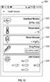
- the HM application 108is operable to generate the GUI 900 to display monitored biosensor data.
- BPMbeats per minute
- the GUI 900may display a Temperature GUI 1202 that illustrates measured temperature of a user, and a Blood Glucose Level GUI 1204 that illustrates measured indicator of blood glucose levels.
- the GUI 900may also illustrate an Activate Pump command GUI 1206 to activate a drug administrative device 210 , such as a drug pump.
- the GUI 900may also illustrate a history of readings of biosensor data.
- the historymay display biosensor data measured over one day, multiple days, one week, one month, one year, or a specified time frame.
- the health monitoring application 108may be implemented in a user device 1000 and generate the GUI 900 , e.g. on a user device, based on biosensor data received from the remote device 100 and/or other external biosensors 150 .
- the HM application 1308may also generate an LED control GUI 1208 .
- a usermay control the operation of the LEDs of the remote control 100 using the LED control GUI 1208 .
- FIG. 13illustrates a schematic block diagram of an embodiment of a graphical user interface (GUI) 600 generated by the health monitoring application 108 .
- the health monitoring application 108may be implemented in the television 102 or a user device and generate the GUI 900 , e.g. on the television 102 or the user device 1000 .
- the GUI 900displays a Settings GUI 1300 for a user to designate settings for the GUI 900 .
- the Settings GUI 1300may enable a user to select the various biosensor data displayed, such as heartbeat, temperature, glucose, etc.
- the health monitoring application 108may also include a poll period GUI 1302 .
- the poll period GUI 1302provides an interface for a user to select or input a time period or polling period for a biosensor measurement or other monitoring.
- FIG. 14Aillustrates a logical flow diagram of an embodiment of a method 1400 for the health monitoring application 108 .
- the HM application 108may generate a GUI 900 at 1402 .
- the GUI 900displays one or more commands for controlling a biosensor 150 on the television 102 or on the user device 1000 at 1404 .
- the HM application 108may receive a user input selecting a command at 1406 .
- the user inputmay be transmitted from the remote device 100 to the television 102 .
- the HM application 108generates a command in response to the user input at 1408 .
- the HM applicationinitiates transmission of the command by the wireless transceiver of the television 102 to the remote device 100 .
- the remote device 100may then transmit the command to an external biosensor to perform the command or initiate an integrated biosensor to perform the command at 1410 .
- FIG. 14Billustrates a logical flow diagram of an embodiment of a method 1420 for the health monitoring (HM) application 108 .
- the HM application 108is implemented in a television 100 and receives biosensor data from a remote device 100 at 1422 .
- the HM application 108may generate a GUI 900 in response to user input at 1424 that displays biosensor data on the television 102 at 1426 .
- the HM application 108may receive updated biosensor data from the remote device 100 .
- the HM application 108then updates the display based on the updated biosensor data at 1428 .
- the HM application 108may also receive a user input to activate a Drug Administration Device at 1430 .
- the HM application 108activates a Drug Administration Device when one or more measurements of biosensor data exceed one or more predetermined thresholds at 1432 . For example, when glucose levels of a user exceed a predetermined threshold, the HM application 108 may activate an insulin pump to administer insulin to the user.
- the HM applicationmay also transmit biosensor data to third parties, such as a doctor's office or pharmacy at 1434 .
- the HM application 108may generate messages that include requests to refill medications that are transmitted to a pharmacy over a wide area network (WAN).
- the HM application 108may generate messages that include biosensor data that are transmitted to a doctor's hospital over a wide area network (WAN).
- WANwide area network
- FIG. 15illustrates a schematic block diagram of an embodiment of an exemplary communication network 1500 in which the devices described herein may operate.
- the exemplary communication network 1500includes one or more networks that are communicatively coupled, such as a wide area network (WAN) 1512 , a wired or wireless local area network (LAN) 1516 , a wireless local area network (WLAN) 1516 , and a wireless wide area network (WAN) 1512 .
- the LAN 1518 and the WLANs 1516may operate inside a home or enterprise environment, such as a doctor's office, pharmacy or hospital or other caregiver or business.
- the wireless WAN 1514may include, for example, a 3G or 4G cellular network, a GSM network, a WIMAX network, an EDGE network, a GERAN network, etc. or a satellite network or a combination thereof.
- the WAN 1512includes the Internet, service provider network, other type of WAN, or a combination of one or more thereof.
- the central application server 1510includes a network interface circuit 1502 and a server processing circuit 1504 .
- the network interface circuit 1502includes an interface for wireless and/or wired network communications with one or more of the exemplary networks in the communication network 1500 .
- the network interface circuit 1502may also include authentication capability that provides authentication prior to allowing access to some or all of the resources of the central application server 1510 .
- the network interface circuit 1502may also include firewall, gateway and proxy server functions.
- the central application server 1510also includes a server processing circuit 1504 and a memory device 1506 .
- the memory device 1506is a non-transitory, processor readable medium that stores instructions from the health monitoring server application 108 which when executed by the server processing circuit 1504 , causes the server processing circuit 1504 to perform one or more functions described herein.
- the memory device 1506stores biosensor data for a plurality of patients transmitted to the central application server 1510 from the plurality of televisions 102 and/or user devices 1000 .
- the central application server 1510includes a health monitoring server application 1508 .
- the health monitoring server application 1508is operable to communicate with the plurality of televisions 102 and/or user devices 700 .
- the health monitoring server application 1508may be a web-based application supported by the central application server 1400 .
- the central application server 1510may be a web server and support the health monitoring server application 1508 via a website.
- the health monitoring application 1508is a stand-alone application that is downloaded to the user devices 1000 by the central application server 1510 and is operable on the user devices 1000 without access to the central application server 1510 or only needs to accesses the central application server 1510 for additional information, such as biosensor data.
- the the plurality of televisions 102 and/or user devices 700are configured to track biosensor data and control certain functions of the the plurality of televisions 102 and/or user devices 700 .
- the health monitoring server application 1508supports a user application on one or more of the plurality of televisions 102 and/or user devices 700 .
- the remote devices 100may communicate directly with one or more televisions 102 and with the one or more user devices 700 .
- the remote devices 100may communicate using an IR signal with a television 102 and may communicate using a Bluetooth connection with a user device 1000 .
- the central application server 1510may also be operable to communicate with a third party content provider 1208 over the communication network 1220 to provide biosensor data.
- the health monitoring application 108may provide biosensor data and channel data 1540 to the third party service provider 1530 .
- the health monitoring application 108may transmit heart rate information or pulse rate information and channel or television tuning data to the third party service provider 1530 .
- the third party service provider 1530may include a cable provider or broadcast television provider that uses the information to determine interest in a may also transmit the messages to a doctor's office, pharmacy or hospital or other caregiver or business over the communication network 1500 as requested or needed.
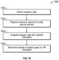
- FIG. 16illustrates a logic flow diagram of an exemplary embodiment of a method 1600 for analyzing content based on HM information.
- the third party service provideris configured to receive and process biosensor data from the remote 100 and television 102 .
- the remote 102is configured to receive and monitor bio sensor data from one or more external or integrated biosensors 150 .
- the biosensors 150may detect an indicator of glucose levels, alcohol levels or other analytes.
- the biosensor 150may also include a pulse oximeter to determine pulse and oxygen levels.
- the biosensor 150may also detect blood pressure, peripheral oxygen (SpO2) saturation amounts, body temperature, various electrolytes and many common blood analytic levels, such as bilirubin amount and sodium and potassium.
- the biosensormay also detect blood alcohol levels.
- the biosensor datais obtained by the remote device 100 at 1602 and transmitted to the television 102 .
- the television 102transmits biosensor data to the third party service provider 1530 at 1604 .
- the third party service provideranalyzes the biosensor data and channel information 1606 .
- the biosensor datamay include pulse rate or activity levels.
- the third party service providerdetermines an interest in television show or channel by a user at 1608 .
- the third party service providermay determine the user has an interest in the channel content, such as a commercial or television show.
- FIG. 17illustrates a schematic block diagram illustrating an embodiment of the PPG circuit 224 in more detail.
- the PPG circuit 224implements photoplethysmography (PPG) techniques for obtaining concentration levels or indicators of one or more substances in pulsating arterial blood flow.
- the PPG circuit 224includes a light source 1720 having a plurality of light sources, such as LEDs 1722 a - n , configured to emit light through at least one aperture 1728 a .
- the PPG circuit 224is configured to direct the emitted light at an outer or epidermal layer of skin tissue of a patient.
- the plurality of light sourcesare configured to emit light in one or more spectrums, including infrared (IR) light, ultraviolet (UV) light, near IR light or visible light, in response to driver circuit 1718 .
- the biosensor 150may include a first LED 1722 a that emits visible light and a second LED 1722 b that emits infrared light and a third LED 1722 c that emits UV light, etc.
- one or more of the light sources 1722 a - nmay include tunable LEDs or lasers operable to emit light over one or more frequencies or ranges of frequencies or spectrums in response to driver circuit 1718 .
- the driver circuit 1718is configured to control the one or more LEDs 1722 a - n to generate light at one or more frequencies for predetermined periods of time.
- the driver circuit 118may control the LEDs 1722 a - n to operate concurrently or progressively.
- the driver circuit 118is configured to control a power level, emission period and frequency of emission of the LEDs 1722 a - n .
- the biosensor 150is thus configured to emit one or more frequencies of light in one or more spectrums that is directed at the surface or epidermal layer of the skin tissue of a patient.
- the PPG circuit 224further includes one or more photodetector circuits 1730 a - n .
- a first photodetector circuit 1730may be configured to detect visible light and the second photodetector circuit 1730 may be configured to detect IR light.
- the first photodetector circuit 1730 and the second photodetector circuit 130may also include a first filter 1760 and a second filter 1762 configured to filter ambient light and/or scattered light. For example, in some embodiments, only light received at an approximately perpendicular angle to the skin surface of the patient is desired to pass through the filters.
- the first photodetector circuit 1730 and the second photodetector circuit 1732are coupled to a first A/D circuit 1738 and a second A/D circuit 1740 .
- the A/D circuits 1738 and 1740may also include an amplifier and other components needed to generate the spectral response.
- the plurality of photodetectors 1730is coupled in parallel to a single amplifier and A/D circuit 1738 . The light detected by each of the photodetectors 1730 is thus added and amplified to generate a single spectral response.
- a single photodetector circuit 1730may be implemented operable to detect light over multiple spectrums or frequency ranges.
- the photodetector circuit 1730may include a Digital UV Index/IR/Visible Light Sensor such as Part No. Si1145 from Silicon LabsTM.
- the one or more photodetector circuits 1730include a spectrometer or other type of circuit configured to detect an intensity of light as a function of wavelength or frequency to obtain a spectral response.
- the one or more photodetector circuits 1730detect the intensity of light either transmitted through or reflected from tissue of a patient that enters one or more apertures 1728 b - n of the biosensor 150 .
- the lightmay be detected from transmissive absorption (e.g., through a fingertip or ear lobe) or from reflection (e.g., reflected from a forehead or stomach tissue).
- the photodetector circuits 1730 a - nthen obtain a spectral response of the detected light by measuring the intensity of light either transmitted or reflected to the photodiodes.
- FIG. 18illustrates a schematic block diagram of another exemplary embodiment of the the PPG circuit 224 .
- the biosensor 150is configured for emitting and detecting light through one or more optical fibers 1852 a - c .
- the PPG circuit 224is optically coupled to a plurality of optical fibers 1852 a - c .
- the plurality of optical fibers 1852 a - cincludes a first optical fiber 1852 a optically coupled to the light source 1720 .
- An optical coupler(not shown) to spread the angle of light emitted from the optical fiber 1852 a may also be implemented.
- the optical fiber 1852 amay have a narrow viewing angle such that an insufficient area of skin surface is exposed to the light.
- An optical coupler 1862may be used to widen the viewing angle to increase the area of skin surface exposed to the light.
- a second optical fiber 1852 bis optically coupled to a first photodetector circuit 1730 a and a third optical fiber 1852 c is optically coupled to the second photodetector circuit 1730 n .
- Other configurations and numbers of the plurality of optical fibers 1852may also be implemented.
- the plurality of optical fibers 1852is situated within an outer ear canal to transmit and detect light in the ear canal.
- a light collimator 1816such as a prism, may be used to align a direction of the light emitted from the light source 1720 .
- One or more filters 1760 , 1762may optionally be implemented to receive the reflected light 1742 from the plurality of optical fibers 1852 b , 1852 c . However, the filters 1760 , 1762 may not be needed as the plurality of optical fibers 1852 b , 1852 c may be sufficient to filter ambient light and/or scattered light.
- FIG. 19illustrates a schematic block diagram of an embodiment of the PPG circuit 224 with a plurality of photodetectors 1730 .
- the plurality of photodetectors 1730are situated in different physical positions and orientations in the biosensor 150 .
- at least four photodetectors 1730 a , 1730 b , 1730 c and 1730 dare situated in the biosensor 150 in four different physical positions in a North-South and East-West orientation or polarity.
- the output signals of the plurality of photodetectorsare coupled in parallel to the amplifier and A/D circuit 1738 .
- the light signals detected by each of the photodetectors 1730 through an aperture 1728 in the biosensorare added and amplified to generate a single spectral response.
- the spectral responseis thus more robust and less affected by motion artifacts and movement of the biosensor 150 .
- the LEDs 1722 a - nmay be situated centrally to the physical position of the plurality of photodetectors 1730 .
- the temperature sensor 216may also be physically situated near the PPG circuit 224 to detect temperature through an aperture 1728 .
- One or more of the embodiments of the biosensor 150 described hereinare configured to detect a concentration level or indicator of one or more substances within blood flow, such as analyte levels, nitric oxide levels, insulin resistance or insulin response after caloric intake and predict diabetic risk or diabetic precursors.
- the biosensor 150may detect insulin response, vascular health, cardiovascular sensor, cytochrome P450 proteins (e.g. one or more liver enzymes or reactions), digestion phase 1 and 2 or caloric intake.
- the biosensor 150may even be configured to detect proteins or other elements or compounds associated with cancer.
- the biosensor 150may also detect various electrolytes and many common blood analytic levels, such as bilirubin amount and sodium and potassium.
- the biosensor 150may detect sodium NACL concentration levels in the arterial blood flow to determine dehydration.
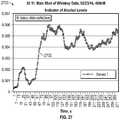
- the biosensor 150may also detect blood alcohol levels in vivo in the arterial blood flow. Because blood flow to the skin can be modulated by multiple other physiological systems, the biosensor 150 may also be used to monitor breathing, hypovolemia, and other circulatory conditions.
- the biosensor 150may also detect blood pressure, peripheral oxygen (SpO 2 or SaO 2 ) saturation, heart rate, respiration rate or other patient vitals.
- the biosensor 150may also be used to detect sleep apnea based on oxygen saturation levels and activity monitoring during sleep.
- the biosensor 150performs PPG techniques using the PPG circuit 224 to detect the concentration levels of substances in blood flow.
- the biosensor 150analyzes reflected visible or IR light to obtain a spectrum response such as, the resonance absorption peaks of the reflected visible, UV or IR light.
- the spectrum responseincludes spectral lines that illustrate an intensity or power or energy at a wavelength or range of wavelengths in a spectral region of the detected light.
- the ratio of the resonance absorption peaks from two different frequenciescan be calculated and based on the Beer-Lambert law used to obtain various levels of substances in the blood flow.
- the spectral response of a substance or substances in the arterial blood flowis determined in a controlled environment, so that an absorption coefficient ⁇ g1 can be obtained at a first light wavelength ⁇ 1 and at a second wavelength ⁇ 2 .
- light intensitywill decrease logarithmically with path length l (such as through an artery of length l).
- I in1is the intensity of the initial light at ⁇ 1
- I in2is the intensity of the initial light at ⁇ 2
- ⁇ g1is the absorption coefficient of the substance in arterial blood at ⁇ 1
- ⁇ g2is the absorption coefficient of the substance in arterial blood at ⁇ 2
- ⁇ w1is the absorption coefficient of arterial blood at ⁇ 1
- ⁇ w1is the absorption coefficient of arterial blood at ⁇ 2
- C gwis the concentration of the substance and arterial blood
- C wis the concentration of arterial blood
- the concentration of the substance Cgmay then be equal to:
- the biosensor 150may thus determine the concentration of various substances in arterial blood using spectroscopy at two different wavelengths using Beer-Lambert principles.
- the biosensor 150determines concentration of one or more substances using Beer-Lambert principles.
- the biosensor 150transmits light at least at a first predetermined wavelength and at a second predetermined wavelength.
- the biosensor 150detects the light (reflected from the skin or transmitted through the skin) and analyzes the spectral response at the first and second wavelengths to detect an indicator or concentration level of one or more substances in the arterial blood flow.
- the first predetermined wavelengthis selected that has a high absorption coefficient for the targeted substance while the second predetermined wavelength is selected that has a low absorption coefficient for the targeted substance.
- the spectral response for the first predetermined wavelengthhave a higher intensity level than the spectral response for the second predetermined wavelength.
- the biosensor 150may transmit light at the first predetermined wavelength and in a range of approximately 1 nm to 50 nm around the first predetermined wavelength.
- the biosensor 150may transmit light at the second predetermined wavelength and in a range of approximately 1 nm to 50 nm around the second predetermined wavelength.
- the range of wavelengthsis determined based on the spectral response since a spectral response may extend over a range of frequencies, not a single frequency (i.e., it has a nonzero linewidth).
- the light that is reflected or transmitted light by the target substancemay by spread over a range of wavelengths rather than just the single predetermined wavelength.
- the center of the spectral responsemay be shifted from its nominal central wavelength or the predetermined wavelength.
- the range of 1 nm to 50 nmis based on the bandwidth of the spectral response line and should include wavelengths with increased light intensity detected for the targeted substance around the predetermined wavelength.
- the first spectral response of the light over the first range of wavelengths including the first predetermined wavelength and the second spectral response of the light over the second range of wavelengths including the second predetermined wavelengthsis then generated.
- the biosensor 150analyzes the first and second spectral responses to detect an indicator or concentration level of one or more substances in the arterial blood flow.
- Photoplethysmographyis used to measure time-dependent volumetric properties of blood in blood vessels due to the cardiac cycle.
- the heartbeataffects volume of arterial blood flow and the concentration of absorption levels being measured in the arterial blood flow.
- pulsating arterial bloodchanges the volume of blood flow in an artery.
- Incident light I Ois directed at a tissue site and a certain amount of light is reflected or transmitted and a certain amount of light is absorbed.
- the reflected/transmitted light I Lis at a minimum due to absorption by the venous blood, nonpulsating arterial blood, pulsating arterial blood, other tissue, etc.
- the transmitted/reflected light I His at a maximum due to lack of absorption from the pulsating arterial blood.
- the biosensor 150is configured to filter the reflected/transmitted light I L of the pulsating arterial blood from the transmitted/reflected light I H . This filtering isolates the light due to reflection/transmission of substances in the pulsating arterial blood from the light due to reflection/transmission from venous (or capillary) blood, other tissues, etc. The biosensor 150 may then measure the concentration levels of one or more substances from the reflected/transmitted light I L in the pulsating arterial blood. Though the above has been described with respect to arterial blood flow, the same principles described herein may be applied to venous blood flow.
- the relative magnitudes of the AC and DC contributions to the reflected/transmitted light signal Imay be used to substantially determine the differences between the diastolic time and the systolic points.
- the difference between the reflected light I L and reflected light I Hcorresponds to the AC contribution of the reflected light (e.g. due to the pulsating arterial blood flow).
- a difference functionmay thus be computed to determine the relative magnitudes of the AC and DC components of the reflected light I to determine the magnitude of the reflected light I L due to the pulsating arterial blood.
- the described techniques herein for determining the relative magnitudes of the AC and DC contributionsis not intended as limiting. It will be appreciated that other methods may be employed to isolate or otherwise determine the relative magnitude of the light I L due to pulsating arterial blood flow.
- FIG. 20illustrates a schematic diagram of a graph of actual clinical data obtained using PPG techniques at a plurality of wavelengths.
- the biosensor 150emits light having a plurality of wavelengths during a measurement period.
- the light at each wavelength (or range of wavelengths)may be transmitted concurrently or sequentially.
- the intensity of the reflected light at each of the wavelengths (or range of wavelengths)is detected and the spectral response is measured over the measurement period.
- the spectral response 2006 for the plurality of wavelengths obtained using the biosensor in clinical trialsis shown in FIG. 20 .
- two biosensors 150 attached to two separate fingertips of a patientwere used to obtain the spectral responses 2006 .
- the first biosensor 150obtained the spectral response for a wavelength at 940 nm 2010 , a wavelength at 660 nm 2012 and a wavelength at 390 nm 2014 .
- the second biosensor 150obtained the spectral response for a wavelength at 940 nm 2016 , a wavelength at 592 nm 2018 and a wavelength at 468 nm 2020 .
- the spectral response of each wavelengthmay be aligned based on the systolic 2002 and diastolic 2004 points in their spectral responses. This alignment is useful to associate each spectral response with a particular stage or phase of the pulse-induced local pressure wave within the blood vessel (which may mimic the cardiac cycle 2008 and thus include systolic and diastolic stages and sub-stages thereof). This temporal alignment helps to determine the absorption measurements acquired near a systolic point in time of the cardiac cycle 2008 and near the diastolic point in time of the cardiac cycle 2008 associated with the local pressure wave within the patient's blood vessels.
- This measured local pulse timing informationmay be useful for properly interpreting the absorption measurements in order to determine the relative contributions of the AC and DC components measured by the biosensor 150 . So for one or more wavelengths, the systolic points 2002 and diastolic points 2004 in the spectral response are determined. These systolic points 2002 and diastolic points 2004 for the one or more wavelengths may then be aligned as a method to discern concurrent responses across the one or more wavelengths.
- the systolic points 2002 and diastolic points 2004 in the absorbance measurementsare temporally correlated to the pulse-driven pressure wave within the arterial blood vessels—which may differ from the cardiac cycle.
- the biosensor 150may concurrently measure the intensity reflected at each the plurality of wavelengths. Since the measurements are concurrent, no alignment of the spectral responses of the plurality of wavelengths may be necessary.
- FIG. 21illustrates a logical flow diagram of an embodiment of a method 2100 of the biosensor 150 .
- the biosensor 150emits and detects light at a plurality of predetermined frequencies or wavelengths, such as approximately 940 nm, 660 nm, 390 nm, 592 nm, and 468 nm.
- the lightis pulsed for a predetermined period of time (such as 100 usec or 200 Hz) sequentially at each predetermined wavelength.
- lightmay be pulsed in a wavelength range of 1 nm to 50 nm around each of the predetermined wavelengths. Then, the spectral responses are obtained for the plurality of wavelengths at 2102 .
- the spectral responsemay be measured over a predetermined period (such as 300 usec.). This measurement process is repeated sequentially pulsing the light and obtaining spectral measurements over a desired measurement period, e.g. from 1-2 seconds to 1-2 minutes or 2-3 hours or continuously over days or weeks. Because the human pulse is typically on the order of magnitude of one 1 HZ, typically the time differences between the systolic and diastolic points are on the order of magnitude of milliseconds or tens of milliseconds or hundreds of milliseconds. Thus, spectral response measurements may be obtained at a frequency of around 10-100 Hz over the desired measurement period.
- a low pass filter(such as a 5 Hz low pass filter) is applied to the spectral response signal at 2104 .
- the relative contributions of the AC and DC componentsare obtained I AC+DC and I AC .
- a peak detection algorithmis applied to determine the systolic and diastolic points at 2106 . Beer Lambert equations are applied as described below at 2108 .
- the L ⁇ valuesare then calculated for one or more of the wavelengths ⁇ , wherein the L ⁇ values for a wavelength equals:
- L ⁇Log ⁇ ⁇ 10 ⁇ ( IAC + DC IDC ) wherein I AC+DC is the intensity of the detected light with AC and DC components and I DC is the intensity of the detected light with the AC filtered by the low pass filter at 2110 .
- the value L ⁇isolates the spectral response due to pulsating arterial blood flow, e.g. the AC component of the spectral response.
- a ratio R of the L ⁇ values at two wavelengthsmay then be determined. For example,
- Ratio ⁇ ⁇ RL ⁇ ⁇ ⁇ ⁇ 1 L ⁇ ⁇ ⁇ ⁇ ⁇ 2
- the L ⁇ values and Ratio Rmay be determined for one or more of the predetermined measurement periods over a desired time period, e.g. from 1-2 seconds to 1-2 minutes or 2-3 hours or continuously over days or weeks to monitor the values.
- the L ⁇ values and Ratio Rmay be used to determine concentration levels of one or more substances in the arterial blood flow at 2112 as well as patient vitals, such as oxygen saturation SpO2, heart rate, respiration rate, etc.
- spectral responseswere obtained during predetermined measurement periods over a 1-2 minute time period at 390 nm and 940 nm.
- An R 390,940 valuewas obtained based on the spectral responses measured during a plurality of the predetermined measurement periods over the 1-2 minute time period. From the unexpected results of the clinical trials, an average or mean R 390,940 value of less than 1 (e.g., approximately 0.5) indicated that a person has diabetes or early onset of diabetes.
- An average or mean R 390,940 value of 2 or aboveindicated that a person has a lower risk of a diabetes diagnosis.
- An average or mean R 390,940 value in the 5-6 rangeindicated no current risk of diabetes.
- a non-invasive, quick 1-2 minute testproduced an indicator of diabetes or diabetic risk in a person.
- the biosensor 150may also function as a pulse oximeter using similar principles under Beer-lambert law to determine pulse and oxygen saturation levels in pulsating arterial flow. For example, a first wavelength at approximately 940 nm and a second wavelength at approximately 660 nm may be used to determine oxygen saturation levels.
- the biosensor 150may also be used to determine alcohol levels in the blood using wavelengths at approximately 390 nm and/or 468 nm.
- an R 468,940 value for at least L 468 nm /L 940 nmmay be used as a liver enzyme indicator, e.g. P450 enzyme indicator.
- an R 592,940 value for at least L 592 nm /L 940 nmmay be used as a digestive indicator to measure digestive responses, such as phase 1 and phase 2 digestive stages.
- the biosensor 150may also detect other types of electrolytes or analytes, such as sodium and potassium, using similar PPG techniques.
- the biosensor 150may detect which blood cell levels in arterial blood flow using similar PPG techniques.
- abnormal cells or proteins or compounds that are present or have higher concentrations in the blood with persons having cancermay be detected using similar PPG techniques described herein at one or more other wavelengths.
- cancer riskmay then be obtained through non-invasive testing by the biosensor 150 .
- biosensor 150may operate in multiple frequencies, various health monitoring tests may be performed concurrently and continuously. These tests may be performed throughout a hospital stay or may be non-invasively and quickly and easily obtained using the biosensor 150 in a physician's office or other clinical setting or at home. These and other aspects of the biosensor 150 are described in more detail herein with clinical trial results.
- FIG. 22illustrates a logical flow diagram of an embodiment of a method 2200 of determining concentration levels of one or more substances in more detail.
- the biosensor 150obtains a first spectral response signal including a first wavelength and a second response signal including a second wavelength at 2202 .
- the first wavelengthis selected that has a high absorption coefficient for the targeted substance while the second wavelength is selected that has a low absorption coefficient for the targeted substance.
- the spectral response for the first predetermined wavelengthhave a higher intensity level than the spectral response for the second predetermined wavelength.
- Each of the spectral response signalsincludes AC and DC components I AC+DC .
- a low pass filteris applied to the spectral response signals I AC+DC to isolate the DC component of the first and second spectral response signals I DC at 2204 .
- the AC fluctuationis due to the pulsatile expansion of the arteriolar bed due to the volume increase in arterial blood.
- measurementsare taken at different times and a peak detection algorithm or other means is used to determine the diastolic point and the systolic point of the spectral response at 2206 .
- the systolic and diastolic measurementsare compared in order to compute the aforementioned R ratio.
- a logarithmic functionmay be applied to the ratio of I AC+DC and I DC to obtain an L value for the first wavelength L ⁇ 1 at 2208 and for the second wavelength L ⁇ 2 at 2210 .
- the ratio R of the L ⁇ valuesmay then be calculated at 2212 .
- the L ⁇ values and Ratio Rmay be used to determine concentration levels of one or more substances in the arterial blood flow at 2214 .
- the biosensor 150may include a broad spectrum light source 1020 , such as a white light to infrared (IR) or near IR LED 1022 , that emits light with wavelengths from e.g. 350 nm to 2500 nm.
- a broad spectrum light sourcewith different ranges may be implemented.
- a broad spectrum light sourcewith a range across 100 nm wavelengths to 2000 nm range of wavelengths in the visible, IR and/or UV frequencies.
- a broadband tungsten light source for spectroscopymay be used.
- the spectral response of the reflected lightis then measured across the wavelengths in the broad spectrum, e.g. from 350 nm to 2500 nm, concurrently.
- a charge coupled device (CCD) spectrometer 1030may be configured to measure the spectral response of the detected light over the broad spectrum.
- CCDcharge coupled device
- the spectral response of the reflected lightis analyzed for a plurality of wavelengths, e.g. at 10 nm to 15 nm to 20 nm, incremental wavelengths across the wavelengths from 10 nm to 2500 nm.
- the processing described with respect to FIG. 21is performed at the plurality of wavelengths.
- the L valuesare calculated at incremental wavelengths, such as at 1 nm or 1.5 nm or 2 nm incremental wavelengths. This process may be used to determine one or more wavelengths or ranges of wavelengths useful in detection for one or more substances in the arterial blood flow. For example, a spectral response around a wavelength of 500 nm may have a higher intensity.
- Trialsmay then be conducted to determine the one or more substances in the blood that generates this spectral response.
- a known substancemay be present in the blood and the spectral response across the broad spectrum is then analyzed to determine a pattern or correlation of intensities of wavelengths in the spectral response to the known substance.
- a pattern of intensities of wavelengths across a range of wavelengthsmay indicate the presence of a substance.
- the intensities of the wavelengthsmay then be analyzed to determine concentration levels of the substance as described in more detail herein.
- the spectral responseis analyzed at a set of predetermined wavelengths (or a range of 1 nm to 50 nm including each predetermined wavelength).
- the L valuesare calculated for the set of predetermined wavelengths using the analyzed spectral responses.
- the concentration levels of one or more substancesmay then be determined based on absorption coefficients for the one or more substances at each of the predetermined wavelengths.
- the concentration levels of a plurality of substancesmay be determined using the spectral response of a plurality of frequencies at 2214 .
- the biosensor 150may thus be used to detect a plurality of substances based on data obtained during a single measurement period.
- the biosensor 150may thus perform a blood panel analysis based on in vivo arterial blood flow in a relatively short measurement period of 1-5 minutes.
- the blood panel analysismay be performed in a physician's office to determine results of the test while the patient is in the office.
- the biosensor 150may thus provide blood panel analysis results in a 1-5 minute measurement period without a need for blood samples and lab tests that may take hours or days or weeks to obtain.
- FIG. 23Aillustrates a graph of an embodiment of an output of a broad spectrum light source.
- the relative light intensity or power output of the broad spectrum light sourceis shown versus wavelength of the output light I O .
- the light intensity or power of the output lightextends from wavelengths of approximately 350 nm to approximately 2500 nm.
- a broad spectrum light sourceemits light with power across the wavelengths from 350 nm to 2500 nm.
- Broad spectrum light sources with different rangesmay be implemented.
- FIG. 23Billustrates a graph with an embodiment of an exemplary spectral response of detected light 2304 across a broad spectrum, e.g. from approximately 10 nm to 2000 nm.
- the spectral response of the detected light 2304may be analyzed at a plurality of wavelengths, e.g. at a set of predetermined wavelengths or at incremental wavelengths.
- the spectral response of wavelengths with a detected intensity or power exceeding a predetermined thresholdmay be analyzed.
- the spectral response at wavelengths of 200 nm, 680 nm and 990 nm (and ranges of +/ ⁇ 20 to 50 nm around these wavelengths) exceeding a relative intensity threshold of 20000may be analyzed.
- FIG. 24illustrates a schematic block diagram of an embodiment of a method 2400 for determining concentration levels or indicators of substances in pulsating blood flow in more detail.
- the biosensor 150obtains a spectral response signal at a first wavelength and at a second wavelength at 2402 .
- the spectral response signalincludes AC and DC components IAC+DC.
- a low pass filteris applied to the spectral response signal IAC+DC to isolate the DC component 2406 of the spectral response signal at each wavelength at 2404 .
- the AC fluctuationis due to the pulsatile expansion of the arteriolar bed due to the volume increase in arterial blood.
- a peak detection algorithm or other meansis used to determine the diastolic point and the systolic point of the spectral response at 2408 .
- the systolic and diastolic measurementsare compared in order to compute the L values using Beer-Lambert equations at 2410 .
- a logarithmic functionmay be applied to the ratio of IAC+DC and IDC to obtain an L value for the first wavelength L ⁇ 1 and for the second wavelength L ⁇ 2 .
- the ratio R of the first wavelength L ⁇ 1 and for the second wavelength L ⁇ 2may then be calculated at 2412 .
- Beer-Lambert principlesare applied to the ratios R at 2414 .
- the linear function described hereinare applied at 2416 , and the one or more concentration levels of the substances or analytes are determined at 2418 .
- a substances or analytemay be attached in the blood stream to one or more hemoglobin compounds.
- the concentration level of the hemoglobin compoundsmay then need to be subtracted from the concentration level of the substance to isolate the concentration level of the substance from the hemoglobin compounds.
- nitric oxideNO
- the measurements at L 390 nm to detect nitric oxidemay include a concentration level of the hemoglobin compounds as well as nitric oxide.
- the hemoglobin compound concentration levelsmay be determined and subtracted to isolate the concentration level of the substance at 2420 .
- the hemoglobin compoundsinclude, e.g., Oxyhemoglobin [HbO2], Carboxyhemoglobin [HbCO], Methemoglobin [HbMet], and reduced hemoglobin fractions [RHb].
- the biosensor 150may control the PPG circuit 110 to detect the total concentration of the hemoglobin compounds using a center frequency of 660 nm and a range of 1 nm to 50 nm.
- a method for determining the relative concentration or composition of different kinds of hemoglobin contained in bloodis described in more detail in U.S. Pat. No. 6,104,938 issued on Aug. 15, 2000, which is hereby incorporated by reference herein.
- the R value obtained from the ratio of L 468 nm /L 940 nmwas identified as an indicator of the liver enzyme marker P450.
- the R value obtained from the ratio of L 592 nm /L 940 nmwas identified as an indicator of digestion phases, such as phase 1 and phase 2, in the arterial blood flow.
- the R value from the ratio of L 660 nm /L 940 nmwas found to be an indicator of oxygen saturation levels SpO 2 in the arterial blood flow.
- the biosensor 150may determine alcohol levels in the blood using spectral responses for wavelengths at 390 and/or 468 nm.
- the second wavelength of 940 nmis selected because it has a low absorption coefficient for the targeted substances described herein.
- another wavelength other than 940 nm with a low absorption coefficient for the targeted substances(e.g. at least less than 25% of the absorption coefficient of the targeted substance for the first wavelength) may be used instead.
- the second wavelength of 940 nmmay be replaced with 860 nm that has a low absorption coefficient for the targeted substances.
- the second wavelength of 940 nmmay be replaced with other wavelengths, e.g. in the IR range, that have a low absorption coefficient for the targeted substances.
- biosensor 150may be detected using similar PPG techniques described herein with biosensor 150 at one or more other wavelengths. Cancer risk may then be determined using non-invasive testing over a short measurement period of 1-10 minutes. Since the biosensor may operate in multiple frequencies, various health monitoring tests may be performed concurrently. For example, the biosensor 150 may measure for diabetic risk, liver enzymes, alcohol levels, cancer risk or presence of other analytes within a same measurement period using PPG techniques.
- FIG. 25illustrates a logical flow diagram of an exemplary method 2500 to determine an absorption coefficients ⁇ of a substance at a wavelength k.
- the concentration level of a substance in arterial bloodis obtained using a known method at 2502 .
- bloodmay be extracted at predetermined intervals during a time period and a blood gas analyzer may be used to measure a concentration level of a substance.
- the biosensor 150emits light at a wavelength (and in one aspect for a range of 1 nm-50 nm around the wavelength) and detects a spectral response for the wavelength (and in one aspect for a range of 1 nm-50 nm around the wavelength) at 2504 .
- the spectral response for the predetermined wavelengthis analyzed at 2506 .
- the intensity of the detected lightis determined.
- the intensity of the detected lightis compared to the known concentration level of the substance at 2508 .
- the absorption coefficient for the substancemay then be determined using the Beer-Lambert equations described herein at
- the above processmay be repeated at one or more other frequencies at 2512 .
- the spectral analysis over a range or at multiple frequenciesmay be analyzed to determine one or more frequencies with a higher intensity or power level in response to a concentration level or presence of the substance.
- one or more frequenciesmay be analyzed and identified for detection of the substance, and the absorption coefficient for the substance determined at the one or more frequencies.
- the concentration level of a substancemay be obtained from predetermined values obtained through experimentation.
- a correlation tablemay be compiled through experimentation that includes light intensity values I 1-n at one or more wavelengths ⁇ 1-n and a corresponding known concentration level for the substance for the light intensity values.
- the biosensor 150detects a spectral response and determines the light intensity values I 1-n at one or more wavelengths ⁇ 1-n .
- the biosensor 150looks up the detected light intensity values I 1-n in the correlation table to determine the concentration level of the substance.
- FIG. 26illustrates a schematic drawing of another exemplary embodiment of results of clinical data 2600 obtained using an embodiment of the biosensor 150 from a second patient.
- the second patientis a 59 year old male with a known diagnosis of Type 2 diabetes.
- blood glucose levelBGL
- BGMblood glucose meter
- the BGM glucose measurements 2604are plotted.
- the plotted measurementswere interpolated to generate a polynomial 2606 showing the approximate BGM glucose measurements over time in mG/DL units.
- the biosensor 150obtained measurements over the same time period to derive the Ratio R for approximately L 390 nm /L 940 nm 2602 , as shown on the graph as well.
- the base insulin resistance factor 2608 measured prior to eatinghas a low baseline value of about 0.5 indicating a diabetic condition.
- the base insulin resistance factor or R value for L 390 nm /L 940 nm of less than 1thus seems to indicate a diabetic condition from the clinical trial results.
- insulin response 2610is seen after about 7 minutes.
- the blood glucose levelsmay be obtained from the R values using the graph 2600 or a similar calibration table that correlates the R value with known BGL measurements for the patient.
- the calibration tablemay be generated for a specific patient or may be generated from a sample of a general population. It is determined that the R values should correlate to similar BGL measurements across a general population. Thus, the calibration table may be generated from testing of a sample of a general population.
- an R value of less than 1(in an R value range of 0-8) indicated that a person has diabetes or early onset of diabetes.
- An R value of 5 (in an R value range of 0-8) or aboveindicated that a person has no diabetic condition.
- the base insulin resistance factor measured using an R value of approximately L 390 nm /L 940 nmhas generally an average value greater than 5 in the first patient without a diabetes diagnosis.
- the base insulin resistance factor measured using an R value of approximately L 390 nm /L 940 nmwas generally an average value less than 1 (in an R value range from 0-8) in the other patients with a diabetes diagnosis of either Type 1 or Type II.
- the base insulin resistance factor measured using an R value in the 1-2(in an R value range from 0-8) range indicated a high risk of diabetes and need for further testing.
- the L 390 nmis measuring NO levels in the arterial blood flow.
- insulinAs insulin is generated in the body, it reacts with blood vessels to generate NO gas. The NO gas bonds to hemoglobin and is transported in the blood stream. The NO is thus a good indicator of a base insulin resistance factor after fasting and an insulin response after caloric intake.
- a base insulin resistance factor of less than 1corresponds to an NO concentration level of at least less than 25% of average NO levels.
- average NO levelsare determined by sampling a general population of persons without diabetes or other health conditions affecting NO levels.
- an R value correlating to a base insulin factor of less than 1indicates that the NO levels are in a range of 25% to 50% less than average NO levels. After fasting, a person with a diabetic condition will have low NO concentration levels that are at least 25% less than average NO levels due to the low level of insulin in the blood.
- an NO concentration level of at least less than 25% of normal ranges of NO concentration levelsindicates a diabetic condition (e.g., the NO levels corresponding to R value less than 1 in this clinical trial).
- a base insulin resistance factor of less than 1correlates to at least less than 25% of average NO levels of a sample population and indicates a diabetic condition.
- a base insulin resistance factor in the range of 2-8corresponds to average NO concentration levels.
- a base insulin resistance factore.g. in the range of 2-8) correlates to an average NO level of a sample population and little to no diabetic risk.
- the biosensor 150may display or transmit, e.g. to a user device or monitoring station, or otherwise output an indicator of the diabetic risk of a patient based on the R value.
- the biosensor 150may output no diabetic risk based on an obtained R value for a patient of 5 or greater.
- the biosensor 150may output low diabetic risk based on an obtained R value of 2-5.
- the biosensor 150may output high diabetic risk based on an obtained R values of 1-2.
- the biosensor 150may output diabetic condition detected based on an R value less than one. In the clinical trials herein, the R value was in a range of 0-8.
- an R value corresponding to at least the lower 10% of the R value rangeindicates a diabetic condition
- an R value in the lower 10% to 25% of the R value rangeindicates a high risk of diabetes
- an R value in the 25% to 60% rangeindicates a low risk of diabetes
- an R value greater than 60%indicates no diabetic condition.
- the R value of L 390 nm /L 940 nmmay be non-invasively and quickly and easily obtained using the biosensor 150 in a physician's office or other clinical setting or at home.
- the R valuemay be used to determine whether further testing for diabetes needs to be performed. For example, upon detection of a low R value of less than 1, a clinician may then determine to perform further testing and monitoring, e.g. using glucose ingestion tests over a longer period of time or using the biosensor 150 over a longer period of time or other type of testing.
- FIG. 27illustrates a schematic drawing of another exemplary embodiment of results of clinical data 2700 obtained using an embodiment of the biosensor 150 from a third patient.
- the third patientwas a 55 year old male that ingested a shot of whiskey at approximately 7 seconds.
- the biosensor 150was used to measure an indicator of blood alcohol levels over a measurement period of approximately 271 seconds using a wavelength of approximately 468 nm.
- the biosensor 150was able to detect the increase in the blood alcohol levels over the measurement period.
- the ratio R values 2702may be correlated with blood alcohol levels using a table or graph that associates the R values 2702 with blood alcohol levels.
- the table or graphmay be obtained through blood alcohol levels measured from blood drawn at preset intervals (such as every 1-5 minutes) during a measurement period (such as 1-5 hours) and interpolating the resulting measurements.
- the interpolated measurementsare then associated with the measured ratio R values 2702 over the same measurement period.
- the ratio R values 2702are consistent with an approximate measured blood alcohol level in subsequent clinical trials for a patient.
- the calibration of measured blood alcohol levels to ratio R values 2702may thus only be performed once for a patient.
- the calibration tablemay be generated using testing of a sample of a general population. It is determined that the R values should correlate to similar BAL measurements across a general population.
- the calibration tablemay be generated from testing of a sample of a general population.
- concentration levels of a liver enzyme called cytochrome P450 Oxidase (P450) that is generated in the presence of alcoholmay be measured by the biosensor 150 .
- the spectral response around the wavelength at approximately 468 nmseems to track the concentration levels of the liver enzyme P450.
- the liver enzymeis generated to react with various substances and may be generated in response to alcohol levels.
- the measurement of the spectral response for the wavelength at approximately 468 nmmay indicate blood alcohol levels and/or concentration levels of P450.
- FIG. 28illustrates a schematic drawing of another exemplary embodiment of results of clinical data 2800 obtained using the biosensor 150 from a fourth patient.
- the biosensor 150was used to measure the digestive stages over a measurement period of approximately 37 minutes using a wavelength of approximately 390 nm to track the blood glucose levels.
- the graphillustrates the values for L 390 nm 2802 obtained over the measurement period.
- the biosensor 150was able to detect the digestive stage 1 2804 and digestive stage 2 2806 based on the obtained values for L 390 nm .
- the first digestive stage 1 2804is indicated by an initial spike around 20 seconds as blood rushes to the stomach to aid in digestion.
- the second digestive stage 2is indicated by a later, more prolonged increase in blood glucose levels between 60 and 180 seconds.
- a calibration of caloric intakemay be performed for a patient.
- known caloric intakesmay be correlated with insulin response in phase 1 and phase 2 digestions measured using values for L 390 nm 2802 .
- the calibration tablemay be generated using testing of a sample of a general population. It is determined that the R values using L 390 nm 2802 and, e.g., L 940 nm should correlate to similar caloric intake measurements across a general population. Thus, the calibration table may be generated from testing of a sample of a general population.
- the biosensor 150may measure concentration levels or indicators of other substances in pulsating blood flow. For example, absorption coefficients for one or more frequencies that have an intensity level responsive to concentration level of substance may be determined. The biosensor 150 may then detect the substance at the determined one or more frequencies as described herein and determine the concentration levels using the Beer-Lambert principles and the absorption coefficients. The L values and R values may be calculated based on the obtained spectral response.
- the biosensor 150may detect various electrolyte concentration levels or blood analyte levels, such as bilirubin (using L 460 nm ) and iron (using L 510 nm , L 651 nm , L 300 nm ) and potassium (using L 550 nm ).
- bilirubinusing L 460 nm
- ironusing L 510 nm , L 651 nm , L 300 nm
- potassiumusing L 550 nm
- the biosensor 150may detect sodium chloride NACL (using L 450 nm ) concentration levels in the arterial blood flow and determine determine dehydration level. The biosensor 150 may then output a determination of level of dehydration based on the detected NACL concentration levels.
- NACLsodium chloride NACL
- the biosensor 150may be configured to detect proteins or abnormal cells or other elements or compounds associated with cancer.
- the biosensor 150may measure concentration levels or indicators of other substances in pulsating blood flow using similar principles described herein.
- the value L ⁇ 1is determined from a spectral response of a wavelength with a high absorption coefficient for the targeted substance.
- the value L ⁇ 2is determined from a spectral response of the wavelength with a low absorption coefficient for the targeted substance.
- the ratio L ⁇ 1, ⁇ 2is determined from the value L ⁇ 1 and the value L ⁇ 2 .
- a calibration tablemay be generated using testing of a sample of a general population that correlates values of the ratio R ⁇ 1, ⁇ 2 to concentration levels of the target substance. Then the concentration level of the targeted substance may be determined using the calibration table and the measured values for the ratio R ⁇ 1, ⁇ 2 .
- the biosensor 150may detect white blood cell levels and determine a presence of an infection. For example, the biosensor 150 may detect the various types of white blood cells based on the spectral response of the wavelengths, e.g. using one or more wavelengths shown in Table 1 below.
- the biosensor 150may detect a color or color change of the blood due to an increase or decrease in white blood cells using one or more wavelengths described in Table 1. Based on the detected color or color change of the blood, the biosensor 150 may output an alert to a presence of an infection. For example, the biosensor 150 monitors the color of the blood. When it detects a color change indicating an increase in white blood cells, the biosensor determines whether this color change meets a predetermined threshold indicating a presence of an infection.
- the predetermined thresholdmay include a color scale and/or length of time of color change. When the color change reaches the predetermined threshold, the biosensor 150 transmits or displays an alert to indicate a presence of an infection.
- the biosensor 150may detect white blood cells from spectral responses at one or more wavelengths. Due to the larger size of the white blood cells from red blood cells, the presence of white blood cells in the blood affects the spectral width and shape of a spectral response.
- FIG. 29illustrates an exemplary graph 2900 of spectral responses of a plurality of wavelengths from clinical data using the biosensor 150 .
- the spectral response of a plurality of wavelengthswas measured using the biosensor 150 over a measurement period of almost 600 seconds or approximately 10 minutes.
- the graphillustrates the L values calculated from the spectral response for a first wavelength 2902 of approximately 940 nm, the spectral response for a second wavelength 2904 of approximately 660 nm and the spectral response for a third wavelength 2906 of approximately 390 nm obtained from a first biosensor 150 measuring reflected light from a first fingertip of a patient.
- the graphfurther illustrates the spectral response for a fourth wavelength 2910 of approximately 592 nm and a fifth wavelength 2914 of approximately 468 nm and the spectral response 1408 again at 940 nm obtained from a second biosensor measuring reflected light from a second fingertip of a patient.
- the spectral responsesare temporally aligned using the systolic and diastolic points. Though two biosensors were used to obtain the spectral responses in this clinical trial, a single biosensor 150 may also be configured to obtain the spectral responses of the plurality of wavelengths.
- the presence of white blood cells in the bloodaffects the spectral width and shape of a spectral response at one or more wavelengths.
- the width and shape of the spectral responseis affected by the presence of white blood cells.
- the width and shape of L660 nm between 250 and 270 secondshas a different shape and width of L66 nm between 300 and 320 seconds in the graph 2900 .
- the differences in the width and shape of the spectral responsemay be used to determine a concentration level of white blood cells or change in concentration level of white blood cells in the blood.
- neutrophil levelsincrease in the presence of an infection.
- the neutrophil particleshave a different color and size from red blood cells.
- the biosensor 150may determine an increase in concentration of neutrophil in response to a change in color of the blood or change in the pattern of the spectral response (L value and/or R value) due to change in size of particles in the blood or a combination of both a change in color and change in a pattern of the spectral response (L value and/or R value).
- a remote device 100communicates with one or more external biosensors, such as an ear biosensor and a skin biosensor, to collect and track biosensor data.
- the remote devicemay also include integrated biosensors.
- a processing circuitincludes at least one processing device, such as a microprocessor, micro-controller, digital signal processor, microcomputer, central processing unit, field programmable gate array, programmable logic device, state machine, logic circuitry, analog circuitry, digital circuitry, and/or any device that manipulates signals (analog and/or digital) based on hard coding of the circuitry and/or operational instructions.
- a memoryis a non-transitory memory device and may be an internal memory or an external memory, and the memory may be a single memory device or a plurality of memory devices.
- the memorymay be a read-only memory, random access memory, volatile memory, non-volatile memory, static memory, dynamic memory, flash memory, cache memory, and/or any non-transitory memory device that stores digital information.
- the term “operable to” or “configurable to”indicates that an element includes one or more of circuits, instructions, modules, data, input(s), output(s), etc., to perform one or more of the described or necessary corresponding functions and may further include inferred coupling to one or more other items to perform the described or necessary corresponding functions.
- the term(s) “coupled”, “coupled to”, “connected to” and/or “connecting” or “interconnecting”includes direct connection or link between nodes/devices and/or indirect connection between nodes/devices via an intervening item (e.g., an item includes, but is not limited to, a component, an element, a circuit, a module, a node, device, network element, etc.).
- inferred connectionsi.e., where one element is connected to another element by inference
- the terms “substantially” and “approximately”provides an industry-accepted tolerance for its corresponding term and/or relativity between items. Such an industry-accepted tolerance ranges from less than one percent to fifty percent and corresponds to, but is not limited to, frequencies, wavelengths, component values, integrated circuit process variations, temperature variations, rise and fall times, and/or thermal noise. Such relativity between items ranges from a difference of a few percent to magnitude differences.
- a processis terminated when its operations are completed.
- a processmay correspond to a method, a function, a procedure, a subroutine, a subprogram, etc.
- a processcorresponds to a function
- its terminationcorresponds to a return of the function to the calling function or the main function.
- the terms “comprise,” “comprises,” “comprising,” “having,” “including,” “includes” or any variation thereofare intended to reference a nonexclusive inclusion, such that a process, method, article, composition or apparatus that comprises a list of elements does not include only those elements recited, but may also include other elements not expressly listed or inherent to such process, method, article, composition, or apparatus.
- Other combinations and/or modifications of the above-described structures, arrangements, applications, proportions, elements, materials, or components used in the practice of the present invention, in addition to those not specifically recited,may be varied or otherwise particularly adapted to specific environments, manufacturing specifications, design parameters, or other operating requirements without departing from the general principles of the same.
Landscapes
- Health & Medical Sciences (AREA)
- Life Sciences & Earth Sciences (AREA)
- Engineering & Computer Science (AREA)
- Physics & Mathematics (AREA)
- Biomedical Technology (AREA)
- Public Health (AREA)
- General Health & Medical Sciences (AREA)
- Animal Behavior & Ethology (AREA)
- Veterinary Medicine (AREA)
- Heart & Thoracic Surgery (AREA)
- Medical Informatics (AREA)
- Pathology (AREA)
- Biophysics (AREA)
- Molecular Biology (AREA)
- Surgery (AREA)
- Physiology (AREA)
- Optics & Photonics (AREA)
- Vascular Medicine (AREA)
- Cardiology (AREA)
- Computer Networks & Wireless Communication (AREA)
- Hematology (AREA)
- Anesthesiology (AREA)
- Spectroscopy & Molecular Physics (AREA)
- Otolaryngology (AREA)
- Oral & Maxillofacial Surgery (AREA)
- Bioinformatics & Cheminformatics (AREA)
- Medicinal Chemistry (AREA)
- Pharmacology & Pharmacy (AREA)
- Dentistry (AREA)
- Emergency Medicine (AREA)
- Chemical & Material Sciences (AREA)
- Radiology & Medical Imaging (AREA)
- Business, Economics & Management (AREA)
- General Business, Economics & Management (AREA)
- Epidemiology (AREA)
- Nuclear Medicine, Radiotherapy & Molecular Imaging (AREA)
- Primary Health Care (AREA)
- Dermatology (AREA)
- Diabetes (AREA)
- Measurement Of The Respiration, Hearing Ability, Form, And Blood Characteristics Of Living Organisms (AREA)
Abstract
Description
At the first wavelength λ1,I1=Iin1*10−(α
At the second wavelength λ2,I2=Iin2*10−(α
wherein:
wherein IAC+DCis the intensity of the detected light with AC and DC components and IDCis the intensity of the detected light with the AC filtered by the low pass filter at2110. The value Lλ isolates the spectral response due to pulsating arterial blood flow, e.g. the AC component of the spectral response.
| TABLE 1 |
| Detection of White Blood Cells |
| White Blood | Spectral Absorption | ||
| Cell Type | Diameter | Color | Wavelengths |
| Neutrophil | 10-12 um | Pink-Red, | Red-660 nm |
| Blue, White | Blue-470 nm | ||
| Green-580 nm | |||
| Eosinophil | 10-12 um | Pink | 660 nm, 470 nm, 580 |
| Orange | |||
| 600 nm | |||
| Basophil | 12-15 um | Blue | 470 nm |
| Lymphocyte | 7-15 um | 633 nm | |
| Monocyte | 15-30 um | 580 nm | |
Claims (17)
Priority Applications (31)
| Application Number | Priority Date | Filing Date | Title |
|---|---|---|---|
| US15/400,916US10750981B2 (en) | 2015-09-25 | 2017-01-06 | System and method for health monitoring including a remote device |
| PCT/US2017/012889WO2017120615A2 (en) | 2016-01-10 | 2017-01-10 | System and method for health monitoring including a user device and biosensor |
| EP17736541.8AEP3399913A4 (en) | 2016-01-10 | 2017-01-10 | MEDICAL SURVEILLANCE SYSTEM AND METHOD INCLUDING A USER DEVICE AND A BIOSENSOR |
| US15/404,117US10932727B2 (en) | 2015-09-25 | 2017-01-11 | System and method for health monitoring including a user device and biosensor |
| PCT/US2017/023077WO2018057058A1 (en) | 2016-09-24 | 2017-03-17 | System and method for atomizing and monitoring a drug cartridge during inhalation treatments |
| US15/462,700US10500354B2 (en) | 2015-09-25 | 2017-03-17 | System and method for atomizing and monitoring a drug cartridge during inhalation treatments |
| US15/622,941US9788767B1 (en) | 2015-09-25 | 2017-06-14 | System and method for monitoring nitric oxide levels using a non-invasive, multi-band biosensor |
| US15/680,991US9968289B2 (en) | 2015-09-25 | 2017-08-18 | System and method for detecting a sepsis condition |
| US15/718,721US10517515B2 (en) | 2017-01-06 | 2017-09-28 | System and method for monitoring nitric oxide levels using a non-invasive, multi-band biosensor |
| US15/804,581US10231674B2 (en) | 2015-09-25 | 2017-11-06 | System and method for health monitoring including a user device and biosensor |
| US15/859,147US10194871B2 (en) | 2015-09-25 | 2017-12-29 | Vehicular health monitoring system and method |
| US15/867,632US10039500B2 (en) | 2015-09-25 | 2018-01-10 | System and method for blood typing using PPG technology |
| US15/898,580US10888280B2 (en) | 2016-09-24 | 2018-02-17 | System and method for obtaining health data using a neural network |
| US15/958,620US10524720B2 (en) | 2017-01-06 | 2018-04-20 | System and method for detecting a health condition using an optical sensor |
| US16/019,518US10945676B2 (en) | 2015-09-25 | 2018-06-26 | System and method for blood typing using PPG technology |
| US16/172,661US10744261B2 (en) | 2015-09-25 | 2018-10-26 | System and method of a biosensor for detection of vasodilation |
| US16/208,358US11375961B2 (en) | 2015-09-25 | 2018-12-03 | Vehicular health monitoring system and method |
| US16/239,417US20190134308A1 (en) | 2015-09-25 | 2019-01-03 | System and method for monitoring blood cell levels in blood flow using ppg technology |
| US16/433,947US10736580B2 (en) | 2016-09-24 | 2019-06-06 | System and method of a biosensor for detection of microvascular responses |
| US16/711,038US11737690B2 (en) | 2015-09-25 | 2019-12-11 | System and method for monitoring nitric oxide levels using a non-invasive, multi-band biosensor |
| US16/730,701US20200146612A1 (en) | 2017-01-06 | 2019-12-30 | System and method for detecting a health condition using an optical sensor |
| US16/779,453US10952682B2 (en) | 2015-07-19 | 2020-01-31 | System and method of a biosensor for detection of health parameters |
| US16/848,646US10973470B2 (en) | 2015-07-19 | 2020-04-14 | System and method for screening and prediction of severity of infection |
| US16/930,133US12011301B2 (en) | 2016-09-24 | 2020-07-15 | System and method of a biosensor for detection of microvascular responses |
| US16/993,944US11980741B2 (en) | 2015-09-25 | 2020-08-14 | System and method of a biosensor for detection of vasodilation |
| US17/127,266US12376802B2 (en) | 2015-09-25 | 2020-12-18 | System and method for health monitoring including a user device and biosensor |
| US17/142,999US20210137464A1 (en) | 2015-09-25 | 2021-01-06 | System and method for obtaining health data using photoplethysmography |
| US17/190,238US12156751B2 (en) | 2015-09-25 | 2021-03-02 | System and method for determining blood disorders for a blood type using PPG technology |
| US17/192,743US20210186435A1 (en) | 2015-07-19 | 2021-03-04 | System and method for screening and prediction of severity of infection |
| US17/199,337US20210259640A1 (en) | 2015-07-19 | 2021-03-11 | System and method of a biosensor for detection of health parameters |
| US17/745,418US20220273247A1 (en) | 2015-09-25 | 2022-05-16 | Vehicular health monitoring system and method |
Applications Claiming Priority (6)
| Application Number | Priority Date | Filing Date | Title |
|---|---|---|---|
| US14/866,500US10321860B2 (en) | 2015-07-19 | 2015-09-25 | System and method for glucose monitoring |
| US201662276934P | 2016-01-10 | 2016-01-10 | |
| US15/275,388US9642578B2 (en) | 2015-07-19 | 2016-09-24 | System and method for health monitoring using a non-invasive, multi-band biosensor |
| US15/275,444US9642538B2 (en) | 2015-07-19 | 2016-09-25 | System and method for a biosensor monitoring and tracking band |
| US15/276,760US9636457B2 (en) | 2015-07-19 | 2016-09-26 | System and method for a drug delivery and biosensor patch |
| US15/400,916US10750981B2 (en) | 2015-09-25 | 2017-01-06 | System and method for health monitoring including a remote device |
Related Parent Applications (8)
| Application Number | Title | Priority Date | Filing Date |
|---|---|---|---|
| US14/866,500Continuation-In-PartUS10321860B2 (en) | 2015-07-19 | 2015-09-25 | System and method for glucose monitoring |
| US15/276,760Continuation-In-PartUS9636457B2 (en) | 2015-07-19 | 2016-09-26 | System and method for a drug delivery and biosensor patch |
| US15/276,760ContinuationUS9636457B2 (en) | 2015-07-19 | 2016-09-26 | System and method for a drug delivery and biosensor patch |
| US15/404,117Continuation-In-PartUS10932727B2 (en) | 2015-07-19 | 2017-01-11 | System and method for health monitoring including a user device and biosensor |
| US15/867,632Continuation-In-PartUS10039500B2 (en) | 2015-09-25 | 2018-01-10 | System and method for blood typing using PPG technology |
| US15/867,632DivisionUS10039500B2 (en) | 2015-09-25 | 2018-01-10 | System and method for blood typing using PPG technology |
| US16/019,518Continuation-In-PartUS10945676B2 (en) | 2015-09-25 | 2018-06-26 | System and method for blood typing using PPG technology |
| US16/391,175Continuation-In-PartUS11744487B2 (en) | 2015-07-19 | 2019-04-22 | System and method for glucose monitoring |
Related Child Applications (16)
| Application Number | Title | Priority Date | Filing Date |
|---|---|---|---|
| US15/275,388Continuation-In-PartUS9642578B2 (en) | 2015-07-19 | 2016-09-24 | System and method for health monitoring using a non-invasive, multi-band biosensor |
| US15/276,760Continuation-In-PartUS9636457B2 (en) | 2015-07-19 | 2016-09-26 | System and method for a drug delivery and biosensor patch |
| US15/404,117ContinuationUS10932727B2 (en) | 2015-07-19 | 2017-01-11 | System and method for health monitoring including a user device and biosensor |
| US15/404,117Continuation-In-PartUS10932727B2 (en) | 2015-07-19 | 2017-01-11 | System and method for health monitoring including a user device and biosensor |
| US15/462,700ContinuationUS10500354B2 (en) | 2015-09-25 | 2017-03-17 | System and method for atomizing and monitoring a drug cartridge during inhalation treatments |
| US15/485,816Continuation-In-PartUS10155087B2 (en) | 2015-07-19 | 2017-04-12 | System and method for a drug delivery and biosensor patch |
| US15/680,991Continuation-In-PartUS9968289B2 (en) | 2015-07-19 | 2017-08-18 | System and method for detecting a sepsis condition |
| US15/859,147Continuation-In-PartUS10194871B2 (en) | 2015-07-19 | 2017-12-29 | Vehicular health monitoring system and method |
| US15/898,580Continuation-In-PartUS10888280B2 (en) | 2015-07-19 | 2018-02-17 | System and method for obtaining health data using a neural network |
| US15/958,620Continuation-In-PartUS10524720B2 (en) | 2015-07-19 | 2018-04-20 | System and method for detecting a health condition using an optical sensor |
| US16/019,518Continuation-In-PartUS10945676B2 (en) | 2015-09-25 | 2018-06-26 | System and method for blood typing using PPG technology |
| US16/172,661Continuation-In-PartUS10744261B2 (en) | 2015-07-19 | 2018-10-26 | System and method of a biosensor for detection of vasodilation |
| US16/433,947Continuation-In-PartUS10736580B2 (en) | 2015-07-19 | 2019-06-06 | System and method of a biosensor for detection of microvascular responses |
| US16/779,453Continuation-In-PartUS10952682B2 (en) | 2015-07-19 | 2020-01-31 | System and method of a biosensor for detection of health parameters |
| US16/848,646Continuation-In-PartUS10973470B2 (en) | 2015-07-19 | 2020-04-14 | System and method for screening and prediction of severity of infection |
| US16/930,133Continuation-In-PartUS12011301B2 (en) | 2016-09-24 | 2020-07-15 | System and method of a biosensor for detection of microvascular responses |
Publications (2)
| Publication Number | Publication Date |
|---|---|
| US20170181678A1 US20170181678A1 (en) | 2017-06-29 |
| US10750981B2true US10750981B2 (en) | 2020-08-25 |
Family
ID=59088592
Family Applications (1)
| Application Number | Title | Priority Date | Filing Date |
|---|---|---|---|
| US15/400,916Active2037-01-09US10750981B2 (en) | 2015-07-19 | 2017-01-06 | System and method for health monitoring including a remote device |
Country Status (1)
| Country | Link |
|---|---|
| US (1) | US10750981B2 (en) |
Cited By (1)
| Publication number | Priority date | Publication date | Assignee | Title |
|---|---|---|---|---|
| US20220133154A1 (en)* | 2020-10-29 | 2022-05-05 | Hong Kong Applied Science and Technology Research Institute Company, Limited | Microbending Fiber-Optic Sensor for Vital Sign Monitoring and Co-Extraction of Respiration and Heartrate |
Families Citing this family (35)
| Publication number | Priority date | Publication date | Assignee | Title |
|---|---|---|---|---|
| US10492684B2 (en) | 2017-02-21 | 2019-12-03 | Arc Devices Limited | Multi-vital-sign smartphone system in an electronic medical records system |
| US10318001B1 (en)* | 2017-04-26 | 2019-06-11 | United Services Automobile Association (Usaa) | Dynamic interface flow based on device location |
| US10602987B2 (en) | 2017-08-10 | 2020-03-31 | Arc Devices Limited | Multi-vital-sign smartphone system in an electronic medical records system |
| US11763665B2 (en)* | 2017-09-11 | 2023-09-19 | Muralidharan Gopalakrishnan | Non-invasive multifunctional telemetry apparatus and real-time system for monitoring clinical signals and health parameters |
| IL275301B2 (en) | 2017-12-12 | 2024-01-01 | Bigfoot Biomedical Inc | Therapy assist information and/or tracking device and related methods and systems |
| US11464459B2 (en)* | 2017-12-12 | 2022-10-11 | Bigfoot Biomedical, Inc. | User interface for diabetes management systems including flash glucose monitor |
| US11077243B2 (en) | 2017-12-12 | 2021-08-03 | Bigfoot Biomedical, Inc. | Devices, systems, and methods for estimating active medication from injections |
| US10987464B2 (en) | 2017-12-12 | 2021-04-27 | Bigfoot Biomedical, Inc. | Pen cap for insulin injection pens and associated methods and systems |
| US11116899B2 (en) | 2017-12-12 | 2021-09-14 | Bigfoot Biomedical, Inc. | User interface for diabetes management systems and devices |
| US11197964B2 (en) | 2017-12-12 | 2021-12-14 | Bigfoot Biomedical, Inc. | Pen cap for medication injection pen having temperature sensor |
| US11083852B2 (en) | 2017-12-12 | 2021-08-10 | Bigfoot Biomedical, Inc. | Insulin injection assistance systems, methods, and devices |
| US11865241B2 (en) | 2017-12-15 | 2024-01-09 | Gastroklenz Inc. | Sensor monitoring system for in-dwelling catheter based treatments |
| WO2019138382A1 (en)* | 2018-01-14 | 2019-07-18 | Gopalakrishnan Muralidharan | Non-invasive blood sugar level monitoring apparatus integrated with real-time health support system |
| DK179980B1 (en) | 2018-03-12 | 2019-11-27 | Apple Inc. | User interfaces for health monitoring |
| US11317833B2 (en) | 2018-05-07 | 2022-05-03 | Apple Inc. | Displaying user interfaces associated with physical activities |
| CN108542360A (en)* | 2018-05-17 | 2018-09-18 | 清华大学 | A kind of intelligent drainage tube and monitoring system using Sensor monitoring much information |
| US12205699B1 (en) | 2018-10-30 | 2025-01-21 | Bigfoot Biomedical, Inc. | Method of pairing therapy devices using shared secrets, and related systems, methods and devices |
| ES2774983B2 (en)* | 2019-01-22 | 2021-06-10 | Univ Sevilla | PORTABLE DEVICE AND METHOD FOR NON-INVASIVE ESTIMATION OF GLUCOSE LEVEL IN BLOOD |
| US11152100B2 (en) | 2019-06-01 | 2021-10-19 | Apple Inc. | Health application user interfaces |
| US11234077B2 (en) | 2019-06-01 | 2022-01-25 | Apple Inc. | User interfaces for managing audio exposure |
| USD903126S1 (en) | 2019-06-26 | 2020-11-24 | Gastroklenz Inc. | Monitoring device |
| USD984637S1 (en) | 2019-06-26 | 2023-04-25 | Gastroklenz Inc. | Measurement vessel |
| US10925549B2 (en) | 2019-06-26 | 2021-02-23 | Gastroklenz Inc. | Systems, devices, and methods for fluid monitoring |
| WO2021007344A1 (en)* | 2019-07-08 | 2021-01-14 | Board Of Regents Of The University Of Nebraska | Drug delivery using microneedle arrays |
| US12002588B2 (en)* | 2019-07-17 | 2024-06-04 | Apple Inc. | Health event logging and coaching user interfaces |
| CN114706505B (en) | 2019-09-09 | 2025-01-28 | 苹果公司 | Research User Interface |
| DK181037B1 (en) | 2020-06-02 | 2022-10-10 | Apple Inc | User interfaces for health applications |
| AU2021283914A1 (en) | 2020-06-02 | 2023-01-19 | Apple Inc. | User interfaces for tracking of physical activity events |
| US11698710B2 (en) | 2020-08-31 | 2023-07-11 | Apple Inc. | User interfaces for logging user activities |
| CN112741626B (en)* | 2020-09-09 | 2022-05-24 | 华为技术有限公司 | Blood oxygen detection method and device with multiple parallel photoelectric detectors |
| USD976921S1 (en)* | 2021-02-25 | 2023-01-31 | Rightpoint Consulting, LLC | Display panel portion with a graphical user interface |
| US12380971B2 (en) | 2021-06-06 | 2025-08-05 | Apple Inc. | User interfaces related to signed clinical data |
| US11915805B2 (en) | 2021-06-06 | 2024-02-27 | Apple Inc. | User interfaces for shared health-related data |
| EP4316371A4 (en)* | 2021-07-05 | 2024-09-25 | Samsung Electronics Co., Ltd. | ELECTRONIC DEVICE AND METHOD FOR MEASURING USER CONTEXT-BASED OXYGEN SATURATION OF AN ELECTRONIC DEVICE |
| CN115429263A (en)* | 2022-09-09 | 2022-12-06 | 青岛海尔空调器有限总公司 | An air-conditioning-based health information processing method and air-conditioning controller |
Citations (155)
| Publication number | Priority date | Publication date | Assignee | Title |
|---|---|---|---|---|
| US4913150A (en) | 1986-08-18 | 1990-04-03 | Physio-Control Corporation | Method and apparatus for the automatic calibration of signals employed in oximetry |
| US5115133A (en) | 1990-04-19 | 1992-05-19 | Inomet, Inc. | Testing of body fluid constituents through measuring light reflected from tympanic membrane |
| US5269310A (en) | 1990-09-06 | 1993-12-14 | Spacelabs Medical, Inc. | Method of measuring blood pressure with a plethysmograph |
| US5358703A (en) | 1993-09-27 | 1994-10-25 | Mcw Research Foundation, Inc. | Method for the detection of nitric oxide |
| US5515847A (en) | 1993-01-28 | 1996-05-14 | Optiscan, Inc. | Self-emission noninvasive infrared spectrophotometer |
| US5673692A (en) | 1995-02-03 | 1997-10-07 | Biosignals Ltd. Co. | Single site, multi-variable patient monitor |
| US5823966A (en) | 1997-05-20 | 1998-10-20 | Buchert; Janusz Michal | Non-invasive continuous blood glucose monitoring |
| US5947911A (en)* | 1997-01-09 | 1999-09-07 | Via Medical Corporation | Method and apparatus for reducing purge volume in a blood chemistry monitoring system |
| US5983121A (en) | 1996-08-30 | 1999-11-09 | Hamamatsu Photonics K.K. | Absorption information measuring method and apparatus of scattering medium |
| US6087087A (en) | 1997-07-03 | 2000-07-11 | Takashi Yonetani | Treatment of hemoglobin with nitric oxide |
| US6280390B1 (en) | 1999-12-29 | 2001-08-28 | Ramot University Authority For Applied Research And Industrial Development Ltd. | System and method for non-invasively monitoring hemodynamic parameters |
| US6285896B1 (en)* | 1998-07-13 | 2001-09-04 | Masimo Corporation | Fetal pulse oximetry sensor |
| US6305804B1 (en) | 1999-03-25 | 2001-10-23 | Fovioptics, Inc. | Non-invasive measurement of blood component using retinal imaging |
| US20020049389A1 (en) | 1996-09-04 | 2002-04-25 | Abreu Marcio Marc | Noninvasive measurement of chemical substances |
| US6537225B1 (en) | 1999-10-07 | 2003-03-25 | Alexander K. Mills | Device and method for noninvasive continuous determination of physiologic characteristics |
| US20030229276A1 (en) | 2000-02-01 | 2003-12-11 | Israel Sarussi | Physiological stress detector device and system |
| US6694180B1 (en) | 1999-10-11 | 2004-02-17 | Peter V. Boesen | Wireless biopotential sensing device and method with capability of short-range radio frequency transmission and reception |
| US20040078219A1 (en) | 2001-12-04 | 2004-04-22 | Kimberly-Clark Worldwide, Inc. | Healthcare networks with biosensors |
| US20040100376A1 (en) | 2002-11-26 | 2004-05-27 | Kimberly-Clark Worldwide, Inc. | Healthcare monitoring system |
| US20040157341A1 (en) | 2003-02-11 | 2004-08-12 | Reynolds Jeffery S. | Multiwavelength readhead for use in the determination of analytes in body fluids |
| US6819950B2 (en) | 2000-10-06 | 2004-11-16 | Alexander K. Mills | Method for noninvasive continuous determination of physiologic characteristics |
| US20050209516A1 (en) | 2004-03-22 | 2005-09-22 | Jacob Fraden | Vital signs probe |
| US20050228244A1 (en) | 2004-04-07 | 2005-10-13 | Triage Wireless, Inc. | Small-scale, vital-signs monitoring device, system and method |
| US20050228299A1 (en) | 2004-04-07 | 2005-10-13 | Triage Wireless, Inc. | Patch sensor for measuring blood pressure without a cuff |
| US6985763B2 (en) | 2001-01-19 | 2006-01-10 | Tufts University | Method for measuring venous oxygen saturation |
| US20060009698A1 (en) | 2004-04-07 | 2006-01-12 | Triage Wireless, Inc. | Hand-held monitor for measuring vital signs |
| US20060094942A1 (en) | 2004-11-04 | 2006-05-04 | Q Step Technologies, Inc. | Non-invasive measurement system and method for measuring the concentration of an optically-active substance |
| US7142901B2 (en)* | 2002-09-25 | 2006-11-28 | Masimo Corporation | Parameter compensated physiological monitor |
| US20060287589A1 (en) | 2005-06-16 | 2006-12-21 | James Wobermin | Digital photoplethysmographic signal sensor |
| WO2007013054A1 (en) | 2005-07-28 | 2007-02-01 | Boris Schwartz | Ear-mounted biosensor |
| US7209775B2 (en) | 2003-05-09 | 2007-04-24 | Samsung Electronics Co., Ltd. | Ear type apparatus for measuring a bio signal and measuring method therefor |
| US20070202605A1 (en) | 2004-06-16 | 2007-08-30 | Allan Doctor | Methods For Identifying And Measuring S-Nitrosothiol Bonds In Heme-Containing Cells And Molecules |
| US20070203405A1 (en) | 2004-10-15 | 2007-08-30 | Yoshiaki Shimomura | Instrument For Noninvasively Measuring Blood Sugar Level |
| US7291497B2 (en) | 2003-09-11 | 2007-11-06 | Theranos, Inc. | Medical device for analyte monitoring and drug delivery |
| US20070260132A1 (en) | 2006-05-04 | 2007-11-08 | Sterling Bernhard B | Method and apparatus for processing signals reflecting physiological characteristics from multiple sensors |
| WO2008006150A1 (en) | 2006-07-11 | 2008-01-17 | Citech Research Ip Pty Ltd | Bio-activity data capture and transmission |
| US7371562B2 (en) | 2000-10-30 | 2008-05-13 | Sru Biosystems, Inc. | Guided mode resonant filter biosensor using a linear grating surface structure |
| US20080146890A1 (en) | 2006-12-19 | 2008-06-19 | Valencell, Inc. | Telemetric apparatus for health and environmental monitoring |
| US20080208019A1 (en) | 2007-02-22 | 2008-08-28 | Jerusalem College Of Technology | Modified Pulse Oximetry Technique For Measurement Of Oxygen Saturation In Arterial And Venous Blood |
| US20080241199A1 (en) | 2007-03-30 | 2008-10-02 | Silverman David G | "Micro-Patch" for Assessment of the Local Microvasculature and Microcirculatory Vasoreactivity |
| US20090043178A1 (en)* | 2006-07-25 | 2009-02-12 | Edward Belotserkovsky | Optical non-invasive blood monitoring system and method |
| US20090156988A1 (en) | 2007-12-18 | 2009-06-18 | Searete Llc, A Limited Liability Corporation Of The State Of Delaware | Circulatory monitoring systems and methods |
| US20090187167A1 (en) | 2007-12-17 | 2009-07-23 | New World Pharmaceuticals, Llc | Integrated intra-dermal delivery, diagnostic and communication system |
| US7647083B2 (en) | 2005-03-01 | 2010-01-12 | Masimo Laboratories, Inc. | Multiple wavelength sensor equalization |
| US20100274101A1 (en) | 2009-04-24 | 2010-10-28 | National Taiwan University | Wireless monitoring bio-diagnosis system |
| WO2010128852A2 (en) | 2009-05-07 | 2010-11-11 | Agis Harmelen Holding B.V. | Ear sensor system for noninvasive measurement of quantities |
| WO2010147968A1 (en) | 2009-06-15 | 2010-12-23 | Yale University | Systems and methods utilizing plethysmographic data for distinguishing arterial and venous saturations |
| US20100331631A1 (en) | 2009-06-30 | 2010-12-30 | Nellcor Puritan Bennett Llc | Oxygen saturation ear sensor design that optimizes both attachment method and signal quality |
| US20110082355A1 (en) | 2009-07-30 | 2011-04-07 | Oxitone Medical Ltd. | Photoplethysmography device and method |
| US20110106050A1 (en) | 2008-04-29 | 2011-05-05 | Ofer Yodfat | Method for Selecting Bolus Doses and Bolus Delivery Patterns in a Drug Delivery Device |
| US7941199B2 (en) | 2006-05-15 | 2011-05-10 | Masimo Laboratories, Inc. | Sepsis monitor |
| US20110137141A1 (en) | 2009-12-03 | 2011-06-09 | At&T Intellectual Property I, L.P. | Wireless Monitoring of Multiple Vital Signs |
| US20110160697A1 (en) | 2008-08-28 | 2011-06-30 | Medingo Ltd. | Device and method for enhanced subcutaneous insulin absorption |
| US20110224518A1 (en) | 2008-07-22 | 2011-09-15 | Jaafar Tindi | Handheld apparatus to determine the viability of a biological tissue |
| US20110275978A1 (en) | 2007-10-30 | 2011-11-10 | Hyde Roderick A | Devices and systems that deliver nitric oxide |
| US20120010683A1 (en) | 2008-12-31 | 2012-01-12 | Koninklijke Philips Electronics N.V. | method and apparatus for controlling a process of injury therapy |
| US20120029363A1 (en) | 2010-07-30 | 2012-02-02 | Nellcor Puritan Bennett Llc | Systems and methods for improved computation of differential pulse transit time from photoplethysmograph signals |
| US20120095302A1 (en) | 2010-10-14 | 2012-04-19 | Sony Corporation | Using tv as health monitor |
| US20120131507A1 (en) | 2010-11-24 | 2012-05-24 | General Electric Company | Patient information timeline viewer |
| US20120136054A1 (en) | 2009-06-03 | 2012-05-31 | Schultz Gregory S | Materials and methods for measuring nitric oxide levels in biological fluids |
| US20120156933A1 (en) | 2010-12-18 | 2012-06-21 | Kevin Kreger | Biosensor Interface Apparatus for a Mobile Communication Device |
| CN102609627A (en) | 2012-03-15 | 2012-07-25 | 四川长虹电器股份有限公司 | Autonomous remote health monitoring system |
| US20120203077A1 (en) | 2011-02-09 | 2012-08-09 | David Da He | Wearable Vital Signs Monitor |
| US20120238844A1 (en) | 2005-06-14 | 2012-09-20 | Dominion Assets, Llc | Method and Apparatus for the Non-Invasive Sensing of Glucose in a Human Subject |
| US8328420B2 (en) | 2003-04-22 | 2012-12-11 | Marcio Marc Abreu | Apparatus and method for measuring biologic parameters |
| US20120330126A1 (en) | 2009-12-23 | 2012-12-27 | Delta, Dansk Elektronik, Lys Og Akustik | Monitoring device for attachment to a surface of a subject |
| US20130030259A1 (en) | 2009-12-23 | 2013-01-31 | Delta, Dansk Elektronik, Lys Og Akustik | Monitoring system |
| US20130060098A1 (en) | 2009-12-23 | 2013-03-07 | Delta, Dansk Elektronik, Lys Og Akustik | Monitoring device |
| US20130066176A1 (en) | 2011-09-09 | 2013-03-14 | Nellcor Puritan Bennett Ireland | Venous oxygen saturation systems and methods |
| US8401605B2 (en) | 2009-04-30 | 2013-03-19 | General Electric Company | Multiple wavelength physiological measuring apparatus, sensor and interface unit for determination of blood parameters |
| WO2013052318A1 (en) | 2011-09-25 | 2013-04-11 | Theranos, Inc. | Systems and methods for multi-analysis |
| US20130110311A1 (en) | 2011-08-29 | 2013-05-02 | Tk Holdings Inc. | System for noninvasive measurement of an analyte in a vehicle driver |
| US20130131474A1 (en)* | 2011-11-22 | 2013-05-23 | Pixart Imaging Inc. | Remote controller and display system |
| US8494507B1 (en) | 2009-02-16 | 2013-07-23 | Handhold Adaptive, LLC | Adaptive, portable, multi-sensory aid for the disabled |
| WO2013127564A1 (en) | 2012-02-27 | 2013-09-06 | Femtotools Ag | System for monitoring drug compliance using high resolution force sensing |
| US20130310669A1 (en) | 2012-05-20 | 2013-11-21 | Jerusalem College Of Technology | Pulmonary pulse oximetry method for the measurement of oxygen saturation in the mixed venous blood |
| US8597274B2 (en) | 2009-05-22 | 2013-12-03 | Abbott Diabetes Care Inc. | Usability features for integrated insulin delivery system |
| US20140046160A1 (en) | 2008-11-04 | 2014-02-13 | Panasonic Corporation | Measurement device |
| US8676284B2 (en) | 2010-10-15 | 2014-03-18 | Novanex, Inc. | Method for non-invasive blood glucose monitoring |
| US20140100432A1 (en) | 2012-10-07 | 2014-04-10 | George Stefan Golda | Wearable Cardiac Monitor |
| US20140112940A1 (en) | 2011-06-20 | 2014-04-24 | Kerry Lane | Mycotoxin diagnostics and methods thereof |
| US8730047B2 (en) | 2004-05-24 | 2014-05-20 | Trutouch Technologies, Inc. | System for noninvasive determination of analytes in tissue |
| US20140194342A1 (en) | 2009-10-05 | 2014-07-10 | Hao Zhang | Peptide-Based Peroxidase Inhibitors and Methods of Using Same |
| US20140243648A1 (en) | 2013-02-22 | 2014-08-28 | Koninklijke Philips N.V. | Marker with light emitting area for use in determining vital sign information |
| US20140253709A1 (en) | 2013-03-06 | 2014-09-11 | Koninklijke Philips N.V. | System and method for determining vital sign information |
| US20140275852A1 (en) | 2012-06-22 | 2014-09-18 | Fitbit, Inc. | Wearable heart rate monitor |
| US20140297313A1 (en) | 2004-08-25 | 2014-10-02 | Carefusion 303, Inc. | System and method for dynamically adjusting patient therapy |
| WO2014163583A1 (en) | 2013-04-05 | 2014-10-09 | Nitto Denko Corporation | METHOD AND APPARATUS FOR DETERMINING SpO2 OF A SUBJECT FROM AN OPTICAL MEASUREMENT |
| US8868149B2 (en) | 2009-07-30 | 2014-10-21 | Oxitone Medical Ltd. | Photoplethysmography device and method |
| US20140316226A1 (en) | 2013-03-14 | 2014-10-23 | Echo Labs, Inc. | Systems and methods of multispectral blood measurement |
| US8888701B2 (en) | 2011-01-27 | 2014-11-18 | Valencell, Inc. | Apparatus and methods for monitoring physiological data during environmental interference |
| US20150066238A1 (en) | 2013-08-27 | 2015-03-05 | Automotive Coalition For Traffic Safety, Inc. | Systems and methods for controlling vehicle ignition using biometric data |
| US20150088007A1 (en) | 2013-09-25 | 2015-03-26 | Bardy Diagnostics, Inc. | Computer-Implemented System And Method For Providing A Personal Mobile Device-Triggered Medical Intervention |
| US20150094914A1 (en) | 2004-02-26 | 2015-04-02 | Geelux Holding, Ltd. | Method and apparatus for biological evaluation |
| US20150109617A1 (en) | 2012-04-30 | 2015-04-23 | Mayo Foundation For Medical Education And Research | Spectrometric systems and methods for improved focus localization of time- and space-varying measurements |
| US20150148635A1 (en) | 2013-11-26 | 2015-05-28 | David Alan Benaron | Rate-Estimation Sensor And Method For Cell Phones, Smart Watches, Occupancy Sensors, And Wearables |
| US20150229341A1 (en)* | 2013-04-06 | 2015-08-13 | Honda Motor Co., Ltd. | System and method for capturing and decontaminating photoplethysmopgraphy (ppg) signals in a vehicle |
| US20150250404A1 (en) | 2012-11-21 | 2015-09-10 | Medical Screening Corporation | Method and apparatus for detection of insulin resistance, diabetes and cardiovascular disease |
| WO2015143197A1 (en) | 2014-03-19 | 2015-09-24 | Case Western Reserve University | Sensor for nitric oxide detection |
| US20150282747A1 (en) | 2012-10-12 | 2015-10-08 | University Of Virginia Patent Foundation | Oxidation measurement system and related method thereof |
| WO2015200148A1 (en) | 2014-06-22 | 2015-12-30 | The University Of North Carolina At Chapel Hill | Extended analytical performance of continuous glucose monitoring devices via nitric oxide |
| US20160018257A1 (en) | 2014-07-16 | 2016-01-21 | Google Inc. | Context Discrimination Using Ambient Light Signal |
| US20160058347A1 (en) | 2008-03-04 | 2016-03-03 | Glt Acquisition Corp. | Flowometry in optical coherence tomography for analyte level estimation |
| US20160058308A1 (en) | 2014-05-01 | 2016-03-03 | Mark Ries Robinson | Pulse Photoplethysmogram System for Diabetes Assessment |
| US20160100781A1 (en) | 2012-05-03 | 2016-04-14 | Vioptix, Inc. | Oximeter Probe with Light Wavelengths to Avoid Surgical Dyes |
| US20160262707A1 (en) | 2013-10-27 | 2016-09-15 | Blacktree Fitness Technologies Inc. | Portable devices and methods for measuring nutritional intake |
| US20160367154A1 (en) | 2014-02-06 | 2016-12-22 | Vita-Sentry Ltd. | Obtaining cardiovascular parameters using arterioles related transient time |
| WO2017001249A1 (en) | 2015-06-30 | 2017-01-05 | Koninklijke Philips N.V. | A sensor system and method which makes use of multiple ppg sensors |
| US9554738B1 (en) | 2016-03-30 | 2017-01-31 | Zyomed Corp. | Spectroscopic tomography systems and methods for noninvasive detection and measurement of analytes using collision computing |
| US20170027521A1 (en) | 2015-08-02 | 2017-02-02 | G Medical Innovation Holdings Ltd. | Device, system and method for noninvasively monitoring physiological parameters |
| US20170071550A1 (en) | 2015-07-19 | 2017-03-16 | Sanmina Corporation | System and method for health monitoring using a non-invasive, multi-band biosensor |
| US20170091436A1 (en) | 2015-09-30 | 2017-03-30 | Apple Inc. | Input devices incorporating biometric sensors |
| US9668701B2 (en) | 2012-11-21 | 2017-06-06 | Medical Screening Corporation | Detection of insulin resistance, diabetes, cardiovascular disease and autonomic neuropathy |
| US9713428B2 (en) | 2011-01-21 | 2017-07-25 | Worcester Polytechnic Institute | Physiological parameter monitoring with a mobile communication device |
| US20170215811A1 (en) | 2015-09-25 | 2017-08-03 | Sanmina Corporation | System and method for health monitoring including a user device and biosensor |
| US20170256110A1 (en) | 2014-01-23 | 2017-09-07 | Apple Inc. | Electronic Device Operation Using Remote User Biometrics |
| US9820656B2 (en) | 2011-07-08 | 2017-11-21 | Lifeq Global Limited | Personalized nutritional and wellness assistant |
| US20170347894A1 (en) | 2016-06-03 | 2017-12-07 | Fourth Frontier Technologies Pvt. Ltd. | System and method for continuous monitoring of blood pressure |
| US20170347899A1 (en) | 2016-06-03 | 2017-12-07 | FOURTH FRONTIER TECHNOLOGIES, Pvt. Ltd. | Method and system for continuous monitoring of cardiovascular health |
| US9839381B1 (en) | 2009-11-24 | 2017-12-12 | Cercacor Laboratories, Inc. | Physiological measurement system with automatic wavelength adjustment |
| US9924895B2 (en) | 2015-04-02 | 2018-03-27 | Livspek Medical Technologies Inc. | Method and apparatus for a spectral detector for noninvasive detection and monitoring of a variety of biomarkers and other blood constituents in the conjunctiva |
| US9949675B2 (en) | 2012-10-19 | 2018-04-24 | Convergence Biometrics, LLC | Noninvasive blood measurement platform |
| US20180117291A1 (en) | 2015-01-28 | 2018-05-03 | Zita S. Netzel | Drug delivery methods and systems |
| US20180140237A1 (en) | 2015-05-26 | 2018-05-24 | Bsx Athletics | Device and method for determining biological indicator levels in tissue |
| US9999355B2 (en) | 2014-02-12 | 2018-06-19 | Koninklijke Philips N.V. | Device, system and method for determining vital signs of a subject based on reflected and transmitted light |
| US20180177416A1 (en) | 2016-04-29 | 2018-06-28 | Fitbit, Inc. | In-canal heart rate monitoring apparatus |
| US20180200433A1 (en) | 2017-01-17 | 2018-07-19 | Denis Baran Cirit | Automatic opioid antagonist injection system |
| US20180264242A1 (en) | 2017-03-16 | 2018-09-20 | AM NOD Inc. | Device for releasing a pharmaceutical onto the skin of a patient |
| WO2018206875A1 (en) | 2017-05-12 | 2018-11-15 | Air Liquide Sante (International) | System and method for monitoring the gas consumption of a patient with transmission of patient identification information |
| US10130285B1 (en) | 2017-09-24 | 2018-11-20 | Wisilica Inc | Wearable apparatus for patient tracking |
| US20180358119A1 (en) | 2016-06-03 | 2018-12-13 | FOURTH FRONTIER TECHNOLOGIES, Pvt. Ltd. | Method and system for continuous monitoring of health parameters during exercise |
| US20180353137A1 (en) | 2017-05-05 | 2018-12-13 | Leah Fe Balajadia | Personal healthcare device |
| US10181021B2 (en) | 2016-02-01 | 2019-01-15 | Fitbit, Inc. | Method and apparatus for off-body detection for wearable device |
| US20190046039A1 (en) | 2017-08-14 | 2019-02-14 | Amrita Vishwa Vidyapeetham | Systems, methods, and devices for remote health monitoring and management |
| US20190050622A1 (en) | 2017-08-09 | 2019-02-14 | Qatar University | Biometric liveness detection through biocompatible capacitive sensor |
| US10206619B1 (en) | 2017-04-28 | 2019-02-19 | Maxim Integrated Products, Inc. | Device and method for monitoring body hydration |
| US10215698B2 (en) | 2014-09-02 | 2019-02-26 | Apple Inc. | Multiple light paths architecture and obscuration methods for signal and perfusion index optimization |
| US20190099114A1 (en) | 2017-09-29 | 2019-04-04 | Sensogram Technologies, Inc. | Fall sensing and medical alert systems |
| US20190110745A1 (en) | 2017-10-12 | 2019-04-18 | Purdue Research Foundation | Methods for detecting heart rate, respiration, and oxygen saturation and uses thereof |
| US20190125963A1 (en) | 2017-10-27 | 2019-05-02 | Microjet Technology Co., Ltd. | Wearable liquid supplying device for human insulin injection |
| US20190125964A1 (en) | 2017-10-27 | 2019-05-02 | Microjet Technology Co., Ltd. | Wearable liquid supplying device for human insulin injection |
| US10278591B2 (en) | 2014-04-29 | 2019-05-07 | Huinno Co., Ltd. | Blood glucose measurement method and apparatus using multiple body signals |
| US20190133471A1 (en) | 2016-04-25 | 2019-05-09 | Performance Athlytics | Method and device for tissue monitoring and heart rate detection |
| EP3488776A1 (en) | 2017-11-23 | 2019-05-29 | Koninklijke Philips N.V. | Wearable device using ppg sensor for optical communication |
| USD850316S1 (en) | 2017-05-22 | 2019-06-04 | Precision Dynamics Corporation | VIR band |
| US10314500B2 (en) | 2014-02-14 | 2019-06-11 | Lifeq Global Limited | Transcutaneous photoplethysmography |
| US10322728B1 (en) | 2018-02-22 | 2019-06-18 | Futurewei Technologies, Inc. | Method for distress and road rage detection |
| WO2019118053A1 (en) | 2017-12-15 | 2019-06-20 | Stc. Unm | Wearable auto injector |
| US20190192086A1 (en) | 2017-12-26 | 2019-06-27 | Amrita Vishwa Vidyapeetham | Spectroscopic monitoring for the measurement of multiple physiological parameters |
| US10342495B2 (en) | 2013-05-17 | 2019-07-09 | Nokia Technologies Oy | Method and system for providing an early risk recognition monitoring |
| US10349847B2 (en) | 2015-01-15 | 2019-07-16 | Samsung Electronics Co., Ltd. | Apparatus for detecting bio-information |
| US10420470B2 (en) | 2015-07-03 | 2019-09-24 | Samsung Electronics Co., Ltd. | Apparatus and method for detecting biological information |
| US10433726B2 (en) | 2017-08-14 | 2019-10-08 | Amrita Vishwa Vidyapeetham | Systems, methods, and devices for remote health monitoring and management using internet of things sensors |
| US10433738B2 (en) | 2014-05-22 | 2019-10-08 | Koninklijke Philips N.V. | Method and apparatus for optical sensing of tissue variation at increased accuracy |
| US20190358387A1 (en) | 2017-12-15 | 2019-11-28 | Gastroklenz Inc. | Sensor monitoring system for in-dwelling catheter based treatments |
- 2017
- 2017-01-06USUS15/400,916patent/US10750981B2/enactiveActive
Patent Citations (216)
| Publication number | Priority date | Publication date | Assignee | Title |
|---|---|---|---|---|
| US4913150A (en) | 1986-08-18 | 1990-04-03 | Physio-Control Corporation | Method and apparatus for the automatic calibration of signals employed in oximetry |
| US5115133A (en) | 1990-04-19 | 1992-05-19 | Inomet, Inc. | Testing of body fluid constituents through measuring light reflected from tympanic membrane |
| US5269310A (en) | 1990-09-06 | 1993-12-14 | Spacelabs Medical, Inc. | Method of measuring blood pressure with a plethysmograph |
| US5515847A (en) | 1993-01-28 | 1996-05-14 | Optiscan, Inc. | Self-emission noninvasive infrared spectrophotometer |
| US5358703A (en) | 1993-09-27 | 1994-10-25 | Mcw Research Foundation, Inc. | Method for the detection of nitric oxide |
| US5673692A (en) | 1995-02-03 | 1997-10-07 | Biosignals Ltd. Co. | Single site, multi-variable patient monitor |
| US5983121A (en) | 1996-08-30 | 1999-11-09 | Hamamatsu Photonics K.K. | Absorption information measuring method and apparatus of scattering medium |
| US20020049389A1 (en) | 1996-09-04 | 2002-04-25 | Abreu Marcio Marc | Noninvasive measurement of chemical substances |
| US5947911A (en)* | 1997-01-09 | 1999-09-07 | Via Medical Corporation | Method and apparatus for reducing purge volume in a blood chemistry monitoring system |
| US5823966A (en) | 1997-05-20 | 1998-10-20 | Buchert; Janusz Michal | Non-invasive continuous blood glucose monitoring |
| US6087087A (en) | 1997-07-03 | 2000-07-11 | Takashi Yonetani | Treatment of hemoglobin with nitric oxide |
| US6285896B1 (en)* | 1998-07-13 | 2001-09-04 | Masimo Corporation | Fetal pulse oximetry sensor |
| US6305804B1 (en) | 1999-03-25 | 2001-10-23 | Fovioptics, Inc. | Non-invasive measurement of blood component using retinal imaging |
| US6537225B1 (en) | 1999-10-07 | 2003-03-25 | Alexander K. Mills | Device and method for noninvasive continuous determination of physiologic characteristics |
| US6719705B2 (en) | 1999-10-07 | 2004-04-13 | Alexander K. Mills | Device and method for noninvasive continuous determination of physiologic characteristics |
| US6921367B2 (en) | 1999-10-07 | 2005-07-26 | Woolsthorpe Technologies, Llc | Device and method for noninvasive continuous determination of physiologic characteristics |
| US6694180B1 (en) | 1999-10-11 | 2004-02-17 | Peter V. Boesen | Wireless biopotential sensing device and method with capability of short-range radio frequency transmission and reception |
| US6280390B1 (en) | 1999-12-29 | 2001-08-28 | Ramot University Authority For Applied Research And Industrial Development Ltd. | System and method for non-invasively monitoring hemodynamic parameters |
| US20030229276A1 (en) | 2000-02-01 | 2003-12-11 | Israel Sarussi | Physiological stress detector device and system |
| US7171251B2 (en) | 2000-02-01 | 2007-01-30 | Spo Medical Equipment Ltd. | Physiological stress detector device and system |
| US6819950B2 (en) | 2000-10-06 | 2004-11-16 | Alexander K. Mills | Method for noninvasive continuous determination of physiologic characteristics |
| US20100191080A1 (en) | 2000-10-06 | 2010-07-29 | Mills Alexander K | Method for noninvasive continuous determination of physiologic characteristics |
| US20110237464A1 (en) | 2000-10-30 | 2011-09-29 | Sru Biosystems, Inc. | Guided Mode Resonant Filter Biosensor Using a Linear Grating Surface Structure |
| US7371562B2 (en) | 2000-10-30 | 2008-05-13 | Sru Biosystems, Inc. | Guided mode resonant filter biosensor using a linear grating surface structure |
| US6985763B2 (en) | 2001-01-19 | 2006-01-10 | Tufts University | Method for measuring venous oxygen saturation |
| US7608045B2 (en) | 2001-11-07 | 2009-10-27 | Woolsthorpe Llc | Method for noninvasive continuous determination of physiologic characteristics |
| US20050101841A9 (en) | 2001-12-04 | 2005-05-12 | Kimberly-Clark Worldwide, Inc. | Healthcare networks with biosensors |
| US20040078219A1 (en) | 2001-12-04 | 2004-04-22 | Kimberly-Clark Worldwide, Inc. | Healthcare networks with biosensors |
| US20150150453A1 (en) | 2002-04-22 | 2015-06-04 | Geelux Holding, Ltd. | Thermal imaging system |
| US7142901B2 (en)* | 2002-09-25 | 2006-11-28 | Masimo Corporation | Parameter compensated physiological monitor |
| WO2004047630A1 (en) | 2002-11-26 | 2004-06-10 | Kimberly-Clark Worldwide, Inc. | Healthcare monitoring system |
| US20040100376A1 (en) | 2002-11-26 | 2004-05-27 | Kimberly-Clark Worldwide, Inc. | Healthcare monitoring system |
| US7154592B2 (en) | 2003-02-11 | 2006-12-26 | Bayer Healthcare Llc. | Multiwavelength readhead for use in the determination of analytes in body fluids |
| US20040157341A1 (en) | 2003-02-11 | 2004-08-12 | Reynolds Jeffery S. | Multiwavelength readhead for use in the determination of analytes in body fluids |
| US8328420B2 (en) | 2003-04-22 | 2012-12-11 | Marcio Marc Abreu | Apparatus and method for measuring biologic parameters |
| US7209775B2 (en) | 2003-05-09 | 2007-04-24 | Samsung Electronics Co., Ltd. | Ear type apparatus for measuring a bio signal and measuring method therefor |
| US20110166553A1 (en) | 2003-09-11 | 2011-07-07 | Holmes Elizabeth A | Medical device for analyte monitoring and drug delivery |
| US7291497B2 (en) | 2003-09-11 | 2007-11-06 | Theranos, Inc. | Medical device for analyte monitoring and drug delivery |
| US10227063B2 (en) | 2004-02-26 | 2019-03-12 | Geelux Holdings, Ltd. | Method and apparatus for biological evaluation |
| US20150094914A1 (en) | 2004-02-26 | 2015-04-02 | Geelux Holding, Ltd. | Method and apparatus for biological evaluation |
| US20050209516A1 (en) | 2004-03-22 | 2005-09-22 | Jacob Fraden | Vital signs probe |
| US7179228B2 (en) | 2004-04-07 | 2007-02-20 | Triage Wireless, Inc. | Cuffless system for measuring blood pressure |
| US20050228244A1 (en) | 2004-04-07 | 2005-10-13 | Triage Wireless, Inc. | Small-scale, vital-signs monitoring device, system and method |
| US20050228299A1 (en) | 2004-04-07 | 2005-10-13 | Triage Wireless, Inc. | Patch sensor for measuring blood pressure without a cuff |
| US20050245831A1 (en) | 2004-04-07 | 2005-11-03 | Triage Wireless, Inc. | Patch sensor for measuring blood pressure without a cuff |
| US20060009698A1 (en) | 2004-04-07 | 2006-01-12 | Triage Wireless, Inc. | Hand-held monitor for measuring vital signs |
| US8730047B2 (en) | 2004-05-24 | 2014-05-20 | Trutouch Technologies, Inc. | System for noninvasive determination of analytes in tissue |
| US20070202605A1 (en) | 2004-06-16 | 2007-08-30 | Allan Doctor | Methods For Identifying And Measuring S-Nitrosothiol Bonds In Heme-Containing Cells And Molecules |
| US7763472B2 (en) | 2004-06-16 | 2010-07-27 | University Of Virginia Patent Foundation | Methods for identifying and measuring S-nitrosothiol bonds in heme-containing cells and molecules |
| US20140297313A1 (en) | 2004-08-25 | 2014-10-02 | Carefusion 303, Inc. | System and method for dynamically adjusting patient therapy |
| US20070203405A1 (en) | 2004-10-15 | 2007-08-30 | Yoshiaki Shimomura | Instrument For Noninvasively Measuring Blood Sugar Level |
| US20060094942A1 (en) | 2004-11-04 | 2006-05-04 | Q Step Technologies, Inc. | Non-invasive measurement system and method for measuring the concentration of an optically-active substance |
| US7167736B2 (en) | 2004-11-04 | 2007-01-23 | Q Step Technologies, Inc. | Non-invasive measurement system and method for measuring the concentration of an optically-active substance |
| US8385996B2 (en) | 2005-03-01 | 2013-02-26 | Cercacor Laboratories, Inc. | Multiple wavelength sensor emitters |
| US8224411B2 (en) | 2005-03-01 | 2012-07-17 | Masimo Laboratories, Inc. | Noninvasive multi-parameter patient monitor |
| US9131882B2 (en) | 2005-03-01 | 2015-09-15 | Cercacor Laboratories, Inc. | Noninvasive multi-parameter patient monitor |
| US7647083B2 (en) | 2005-03-01 | 2010-01-12 | Masimo Laboratories, Inc. | Multiple wavelength sensor equalization |
| US20100049020A1 (en) | 2005-03-01 | 2010-02-25 | Masimo Laboratories, Inc. | Multiple wavelength sensor emitters |
| US7761127B2 (en) | 2005-03-01 | 2010-07-20 | Masimo Laboratories, Inc. | Multiple wavelength sensor substrate |
| US8255027B2 (en) | 2005-03-01 | 2012-08-28 | Cercacor Laboratories, Inc. | Multiple wavelength sensor substrate |
| US7764982B2 (en) | 2005-03-01 | 2010-07-27 | Masimo Laboratories, Inc. | Multiple wavelength sensor emitters |
| US8483787B2 (en) | 2005-03-01 | 2013-07-09 | Cercacor Laboratories, Inc. | Multiple wavelength sensor drivers |
| US20120238844A1 (en) | 2005-06-14 | 2012-09-20 | Dominion Assets, Llc | Method and Apparatus for the Non-Invasive Sensing of Glucose in a Human Subject |
| US20060287589A1 (en) | 2005-06-16 | 2006-12-21 | James Wobermin | Digital photoplethysmographic signal sensor |
| US20080165017A1 (en) | 2005-07-28 | 2008-07-10 | Hippoc Ltd. | Ear-mounted biosensor |
| WO2007013054A1 (en) | 2005-07-28 | 2007-02-01 | Boris Schwartz | Ear-mounted biosensor |
| US20070260132A1 (en) | 2006-05-04 | 2007-11-08 | Sterling Bernhard B | Method and apparatus for processing signals reflecting physiological characteristics from multiple sensors |
| US7941199B2 (en) | 2006-05-15 | 2011-05-10 | Masimo Laboratories, Inc. | Sepsis monitor |
| WO2008006150A1 (en) | 2006-07-11 | 2008-01-17 | Citech Research Ip Pty Ltd | Bio-activity data capture and transmission |
| US20090043178A1 (en)* | 2006-07-25 | 2009-02-12 | Edward Belotserkovsky | Optical non-invasive blood monitoring system and method |
| US20080146890A1 (en) | 2006-12-19 | 2008-06-19 | Valencell, Inc. | Telemetric apparatus for health and environmental monitoring |
| US20150366471A1 (en) | 2006-12-19 | 2015-12-24 | Valencell, Inc. | Physiological Monitoring Systems, Methods and Apparatus |
| US8652040B2 (en) | 2006-12-19 | 2014-02-18 | Valencell, Inc. | Telemetric apparatus for health and environmental monitoring |
| US20080208019A1 (en) | 2007-02-22 | 2008-08-28 | Jerusalem College Of Technology | Modified Pulse Oximetry Technique For Measurement Of Oxygen Saturation In Arterial And Venous Blood |
| US20080241199A1 (en) | 2007-03-30 | 2008-10-02 | Silverman David G | "Micro-Patch" for Assessment of the Local Microvasculature and Microcirculatory Vasoreactivity |
| US8961932B2 (en) | 2007-03-30 | 2015-02-24 | David G. Silverman | “Micro-patch” for assessment of the local microvasculature and microcirculatory vasoreactivity |
| US20110275978A1 (en) | 2007-10-30 | 2011-11-10 | Hyde Roderick A | Devices and systems that deliver nitric oxide |
| US20090187167A1 (en) | 2007-12-17 | 2009-07-23 | New World Pharmaceuticals, Llc | Integrated intra-dermal delivery, diagnostic and communication system |
| US9022973B2 (en) | 2007-12-17 | 2015-05-05 | New World Pharmaceuticals, Llc | Integrated intra-dermal delivery, diagnostic and communication system |
| US20090156988A1 (en) | 2007-12-18 | 2009-06-18 | Searete Llc, A Limited Liability Corporation Of The State Of Delaware | Circulatory monitoring systems and methods |
| US20090287120A1 (en) | 2007-12-18 | 2009-11-19 | Searete Llc, A Limited Liability Corporation Of The State Of Delaware | Circulatory monitoring systems and methods |
| US20160058347A1 (en) | 2008-03-04 | 2016-03-03 | Glt Acquisition Corp. | Flowometry in optical coherence tomography for analyte level estimation |
| US20110106050A1 (en) | 2008-04-29 | 2011-05-05 | Ofer Yodfat | Method for Selecting Bolus Doses and Bolus Delivery Patterns in a Drug Delivery Device |
| US20110224518A1 (en) | 2008-07-22 | 2011-09-15 | Jaafar Tindi | Handheld apparatus to determine the viability of a biological tissue |
| US20170172477A1 (en) | 2008-07-22 | 2017-06-22 | Memorial Sloan-Kettering Cancer Center | Handheld apparatus to determine the viability of a biological tissue |
| US20110160697A1 (en) | 2008-08-28 | 2011-06-30 | Medingo Ltd. | Device and method for enhanced subcutaneous insulin absorption |
| US9387033B2 (en) | 2008-08-28 | 2016-07-12 | Roche Diabetes Care, Inc. | Device and method for enhanced subcutaneous insulin absorption |
| US20140046160A1 (en) | 2008-11-04 | 2014-02-13 | Panasonic Corporation | Measurement device |
| US20120010683A1 (en) | 2008-12-31 | 2012-01-12 | Koninklijke Philips Electronics N.V. | method and apparatus for controlling a process of injury therapy |
| US9149646B2 (en) | 2008-12-31 | 2015-10-06 | Koninklijke Philips N.V. | Method and apparatus for controlling a process of injury therapy |
| US8494507B1 (en) | 2009-02-16 | 2013-07-23 | Handhold Adaptive, LLC | Adaptive, portable, multi-sensory aid for the disabled |
| US20100274101A1 (en) | 2009-04-24 | 2010-10-28 | National Taiwan University | Wireless monitoring bio-diagnosis system |
| US8401605B2 (en) | 2009-04-30 | 2013-03-19 | General Electric Company | Multiple wavelength physiological measuring apparatus, sensor and interface unit for determination of blood parameters |
| WO2010128852A3 (en) | 2009-05-07 | 2010-12-29 | Agis Harmelen Holding B.V. | Ear sensor system for noninvasive measurement of quantities |
| WO2010128852A2 (en) | 2009-05-07 | 2010-11-11 | Agis Harmelen Holding B.V. | Ear sensor system for noninvasive measurement of quantities |
| US8597274B2 (en) | 2009-05-22 | 2013-12-03 | Abbott Diabetes Care Inc. | Usability features for integrated insulin delivery system |
| US8906693B2 (en) | 2009-06-03 | 2014-12-09 | University Of Florida Research Foundation, Inc. | Materials and methods for measuring nitric oxide levels in biological fluids |
| US20120136054A1 (en) | 2009-06-03 | 2012-05-31 | Schultz Gregory S | Materials and methods for measuring nitric oxide levels in biological fluids |
| WO2010147968A1 (en) | 2009-06-15 | 2010-12-23 | Yale University | Systems and methods utilizing plethysmographic data for distinguishing arterial and venous saturations |
| US20150182172A1 (en) | 2009-06-15 | 2015-07-02 | Yale University | Systems and Methods Utilizing Plethysmographic Data for Distinguishing Arterial and Venous Oxygen Saturations |
| US20100331631A1 (en) | 2009-06-30 | 2010-12-30 | Nellcor Puritan Bennett Llc | Oxygen saturation ear sensor design that optimizes both attachment method and signal quality |
| US20150105638A1 (en) | 2009-07-30 | 2015-04-16 | Oxitone Medical Ltd. | Photoplethysmography Device and Method |
| US8868149B2 (en) | 2009-07-30 | 2014-10-21 | Oxitone Medical Ltd. | Photoplethysmography device and method |
| US20110082355A1 (en) | 2009-07-30 | 2011-04-07 | Oxitone Medical Ltd. | Photoplethysmography device and method |
| US9149216B2 (en) | 2009-07-30 | 2015-10-06 | Oxitone Medical Ltd. | Photoplethysmography device and method |
| US20140194342A1 (en) | 2009-10-05 | 2014-07-10 | Hao Zhang | Peptide-Based Peroxidase Inhibitors and Methods of Using Same |
| US9839381B1 (en) | 2009-11-24 | 2017-12-12 | Cercacor Laboratories, Inc. | Physiological measurement system with automatic wavelength adjustment |
| US20110137141A1 (en) | 2009-12-03 | 2011-06-09 | At&T Intellectual Property I, L.P. | Wireless Monitoring of Multiple Vital Signs |
| US20130030259A1 (en) | 2009-12-23 | 2013-01-31 | Delta, Dansk Elektronik, Lys Og Akustik | Monitoring system |
| US9521970B2 (en) | 2009-12-23 | 2016-12-20 | Biotelemetry Technology Aps | Monitoring device for attachment to a surface of a subject |
| US20130060098A1 (en) | 2009-12-23 | 2013-03-07 | Delta, Dansk Elektronik, Lys Og Akustik | Monitoring device |
| US20120330126A1 (en) | 2009-12-23 | 2012-12-27 | Delta, Dansk Elektronik, Lys Og Akustik | Monitoring device for attachment to a surface of a subject |
| US20120029363A1 (en) | 2010-07-30 | 2012-02-02 | Nellcor Puritan Bennett Llc | Systems and methods for improved computation of differential pulse transit time from photoplethysmograph signals |
| US20120095302A1 (en) | 2010-10-14 | 2012-04-19 | Sony Corporation | Using tv as health monitor |
| US8676284B2 (en) | 2010-10-15 | 2014-03-18 | Novanex, Inc. | Method for non-invasive blood glucose monitoring |
| USD824937S1 (en) | 2010-11-24 | 2018-08-07 | General Electric Company | Display screen or portion thereof with graphical user interface |
| US20120131507A1 (en) | 2010-11-24 | 2012-05-24 | General Electric Company | Patient information timeline viewer |
| US20120156933A1 (en) | 2010-12-18 | 2012-06-21 | Kevin Kreger | Biosensor Interface Apparatus for a Mobile Communication Device |
| US8923918B2 (en) | 2010-12-18 | 2014-12-30 | Kallows Engineering India Pvt. Ltd. | Biosensor interface apparatus for a mobile communication device |
| US9713428B2 (en) | 2011-01-21 | 2017-07-25 | Worcester Polytechnic Institute | Physiological parameter monitoring with a mobile communication device |
| US8888701B2 (en) | 2011-01-27 | 2014-11-18 | Valencell, Inc. | Apparatus and methods for monitoring physiological data during environmental interference |
| US20120203077A1 (en) | 2011-02-09 | 2012-08-09 | David Da He | Wearable Vital Signs Monitor |
| WO2012108895A1 (en) | 2011-02-09 | 2012-08-16 | Massachusetts Institute Of Technology | Ear wearable vital sign monitor |
| US9442092B2 (en) | 2011-06-20 | 2016-09-13 | Kerry Lane | Methods for treatment of autism |
| US20140112940A1 (en) | 2011-06-20 | 2014-04-24 | Kerry Lane | Mycotoxin diagnostics and methods thereof |
| US9820656B2 (en) | 2011-07-08 | 2017-11-21 | Lifeq Global Limited | Personalized nutritional and wellness assistant |
| US20130110311A1 (en) | 2011-08-29 | 2013-05-02 | Tk Holdings Inc. | System for noninvasive measurement of an analyte in a vehicle driver |
| US20170050518A1 (en) | 2011-08-29 | 2017-02-23 | Automotive Coalition For Traffic Safety, Inc. | System for non-invasive measurement of an analyte in a vehicle driver |
| US10099554B2 (en) | 2011-08-29 | 2018-10-16 | Automotive Coalition For Traffic Safety, Inc. | System for non-invasive measurement of an analyte in a vehicle driver |
| US20130066176A1 (en) | 2011-09-09 | 2013-03-14 | Nellcor Puritan Bennett Ireland | Venous oxygen saturation systems and methods |
| WO2013052318A1 (en) | 2011-09-25 | 2013-04-11 | Theranos, Inc. | Systems and methods for multi-analysis |
| US20130131474A1 (en)* | 2011-11-22 | 2013-05-23 | Pixart Imaging Inc. | Remote controller and display system |
| WO2013127564A1 (en) | 2012-02-27 | 2013-09-06 | Femtotools Ag | System for monitoring drug compliance using high resolution force sensing |
| CN102609627A (en) | 2012-03-15 | 2012-07-25 | 四川长虹电器股份有限公司 | Autonomous remote health monitoring system |
| US9739663B2 (en) | 2012-04-30 | 2017-08-22 | Mayo Foundation For Medical Education And Research | Spectrometric systems and methods for improved focus localization of time- and space-varying measurements |
| US20150109617A1 (en) | 2012-04-30 | 2015-04-23 | Mayo Foundation For Medical Education And Research | Spectrometric systems and methods for improved focus localization of time- and space-varying measurements |
| US20160100781A1 (en) | 2012-05-03 | 2016-04-14 | Vioptix, Inc. | Oximeter Probe with Light Wavelengths to Avoid Surgical Dyes |
| US20130310669A1 (en) | 2012-05-20 | 2013-11-21 | Jerusalem College Of Technology | Pulmonary pulse oximetry method for the measurement of oxygen saturation in the mixed venous blood |
| US20140275852A1 (en) | 2012-06-22 | 2014-09-18 | Fitbit, Inc. | Wearable heart rate monitor |
| US20140100432A1 (en) | 2012-10-07 | 2014-04-10 | George Stefan Golda | Wearable Cardiac Monitor |
| US20150148622A1 (en) | 2012-10-07 | 2015-05-28 | Rhythm Diagnostics Systems, Inc. | Health monitoring systems and methods |
| US10028682B2 (en) | 2012-10-12 | 2018-07-24 | University Of Virginia Patent Foundation | Oxidation measurement system and related method thereof |
| US20150282747A1 (en) | 2012-10-12 | 2015-10-08 | University Of Virginia Patent Foundation | Oxidation measurement system and related method thereof |
| US9949675B2 (en) | 2012-10-19 | 2018-04-24 | Convergence Biometrics, LLC | Noninvasive blood measurement platform |
| US20150250404A1 (en) | 2012-11-21 | 2015-09-10 | Medical Screening Corporation | Method and apparatus for detection of insulin resistance, diabetes and cardiovascular disease |
| US9668701B2 (en) | 2012-11-21 | 2017-06-06 | Medical Screening Corporation | Detection of insulin resistance, diabetes, cardiovascular disease and autonomic neuropathy |
| US20140243648A1 (en) | 2013-02-22 | 2014-08-28 | Koninklijke Philips N.V. | Marker with light emitting area for use in determining vital sign information |
| US20140253709A1 (en) | 2013-03-06 | 2014-09-11 | Koninklijke Philips N.V. | System and method for determining vital sign information |
| US10463283B2 (en) | 2013-03-14 | 2019-11-05 | Spry Health, Inc. | Systems and methods of multispectral blood measurement |
| US20140316226A1 (en) | 2013-03-14 | 2014-10-23 | Echo Labs, Inc. | Systems and methods of multispectral blood measurement |
| WO2014163583A1 (en) | 2013-04-05 | 2014-10-09 | Nitto Denko Corporation | METHOD AND APPARATUS FOR DETERMINING SpO2 OF A SUBJECT FROM AN OPTICAL MEASUREMENT |
| US20160066863A1 (en) | 2013-04-05 | 2016-03-10 | Nitto Denko Corporation | METHOD AND APPARATUS FOR DETERMINING SpO2 OF A SUBJECT FROM AN OPTICAL MEASUREMENT |
| US20150229341A1 (en)* | 2013-04-06 | 2015-08-13 | Honda Motor Co., Ltd. | System and method for capturing and decontaminating photoplethysmopgraphy (ppg) signals in a vehicle |
| US10153796B2 (en) | 2013-04-06 | 2018-12-11 | Honda Motor Co., Ltd. | System and method for capturing and decontaminating photoplethysmopgraphy (PPG) signals in a vehicle |
| US10342495B2 (en) | 2013-05-17 | 2019-07-09 | Nokia Technologies Oy | Method and system for providing an early risk recognition monitoring |
| US20150066238A1 (en) | 2013-08-27 | 2015-03-05 | Automotive Coalition For Traffic Safety, Inc. | Systems and methods for controlling vehicle ignition using biometric data |
| US20150088007A1 (en) | 2013-09-25 | 2015-03-26 | Bardy Diagnostics, Inc. | Computer-Implemented System And Method For Providing A Personal Mobile Device-Triggered Medical Intervention |
| US20160262707A1 (en) | 2013-10-27 | 2016-09-15 | Blacktree Fitness Technologies Inc. | Portable devices and methods for measuring nutritional intake |
| US20150148635A1 (en) | 2013-11-26 | 2015-05-28 | David Alan Benaron | Rate-Estimation Sensor And Method For Cell Phones, Smart Watches, Occupancy Sensors, And Wearables |
| US20170256110A1 (en) | 2014-01-23 | 2017-09-07 | Apple Inc. | Electronic Device Operation Using Remote User Biometrics |
| US20160367154A1 (en) | 2014-02-06 | 2016-12-22 | Vita-Sentry Ltd. | Obtaining cardiovascular parameters using arterioles related transient time |
| US9999355B2 (en) | 2014-02-12 | 2018-06-19 | Koninklijke Philips N.V. | Device, system and method for determining vital signs of a subject based on reflected and transmitted light |
| US10314500B2 (en) | 2014-02-14 | 2019-06-11 | Lifeq Global Limited | Transcutaneous photoplethysmography |
| WO2015143197A1 (en) | 2014-03-19 | 2015-09-24 | Case Western Reserve University | Sensor for nitric oxide detection |
| US10278591B2 (en) | 2014-04-29 | 2019-05-07 | Huinno Co., Ltd. | Blood glucose measurement method and apparatus using multiple body signals |
| US20160058308A1 (en) | 2014-05-01 | 2016-03-03 | Mark Ries Robinson | Pulse Photoplethysmogram System for Diabetes Assessment |
| US10433738B2 (en) | 2014-05-22 | 2019-10-08 | Koninklijke Philips N.V. | Method and apparatus for optical sensing of tissue variation at increased accuracy |
| WO2015200148A1 (en) | 2014-06-22 | 2015-12-30 | The University Of North Carolina At Chapel Hill | Extended analytical performance of continuous glucose monitoring devices via nitric oxide |
| US20160018257A1 (en) | 2014-07-16 | 2016-01-21 | Google Inc. | Context Discrimination Using Ambient Light Signal |
| US10215698B2 (en) | 2014-09-02 | 2019-02-26 | Apple Inc. | Multiple light paths architecture and obscuration methods for signal and perfusion index optimization |
| US20190086331A1 (en) | 2014-09-02 | 2019-03-21 | Apple Inc. | Multiple light paths architecture and obscuration methods for signal and perfusion index optimization |
| US10349847B2 (en) | 2015-01-15 | 2019-07-16 | Samsung Electronics Co., Ltd. | Apparatus for detecting bio-information |
| US20180117291A1 (en) | 2015-01-28 | 2018-05-03 | Zita S. Netzel | Drug delivery methods and systems |
| US10232156B2 (en) | 2015-01-28 | 2019-03-19 | Chrono Therapeutics Inc. | Drug delivery methods and systems |
| US9924895B2 (en) | 2015-04-02 | 2018-03-27 | Livspek Medical Technologies Inc. | Method and apparatus for a spectral detector for noninvasive detection and monitoring of a variety of biomarkers and other blood constituents in the conjunctiva |
| US20180140237A1 (en) | 2015-05-26 | 2018-05-24 | Bsx Athletics | Device and method for determining biological indicator levels in tissue |
| US10420491B2 (en) | 2015-05-26 | 2019-09-24 | Lvl Technologies, Inc. | Device and method for generating calibration factors for use in determining biological indicator levels in tissue |
| US20180140210A1 (en) | 2015-06-30 | 2018-05-24 | Koninklijke Philips N.V. | Sensor system and method which makes use of multiple ppg sensors |
| US20180177440A1 (en) | 2015-06-30 | 2018-06-28 | Koninklijke Philips N.V. | A sensor system and method which makes use of multiple ppg sensors |
| WO2017001249A1 (en) | 2015-06-30 | 2017-01-05 | Koninklijke Philips N.V. | A sensor system and method which makes use of multiple ppg sensors |
| US10420470B2 (en) | 2015-07-03 | 2019-09-24 | Samsung Electronics Co., Ltd. | Apparatus and method for detecting biological information |
| US9642578B2 (en) | 2015-07-19 | 2017-05-09 | Sanmina Corporation | System and method for health monitoring using a non-invasive, multi-band biosensor |
| US20170071550A1 (en) | 2015-07-19 | 2017-03-16 | Sanmina Corporation | System and method for health monitoring using a non-invasive, multi-band biosensor |
| US20170027521A1 (en) | 2015-08-02 | 2017-02-02 | G Medical Innovation Holdings Ltd. | Device, system and method for noninvasively monitoring physiological parameters |
| US20170215811A1 (en) | 2015-09-25 | 2017-08-03 | Sanmina Corporation | System and method for health monitoring including a user device and biosensor |
| US20170091436A1 (en) | 2015-09-30 | 2017-03-30 | Apple Inc. | Input devices incorporating biometric sensors |
| US10181021B2 (en) | 2016-02-01 | 2019-01-15 | Fitbit, Inc. | Method and apparatus for off-body detection for wearable device |
| US20190251238A1 (en) | 2016-02-01 | 2019-08-15 | Fitbit, Inc. | Method and apparatus for off-body detection for wearable device |
| US9554738B1 (en) | 2016-03-30 | 2017-01-31 | Zyomed Corp. | Spectroscopic tomography systems and methods for noninvasive detection and measurement of analytes using collision computing |
| US20190133471A1 (en) | 2016-04-25 | 2019-05-09 | Performance Athlytics | Method and device for tissue monitoring and heart rate detection |
| US10433739B2 (en) | 2016-04-29 | 2019-10-08 | Fitbit, Inc. | Multi-channel photoplethysmography sensor |
| US20180177416A1 (en) | 2016-04-29 | 2018-06-28 | Fitbit, Inc. | In-canal heart rate monitoring apparatus |
| US20170347894A1 (en) | 2016-06-03 | 2017-12-07 | Fourth Frontier Technologies Pvt. Ltd. | System and method for continuous monitoring of blood pressure |
| US20170347899A1 (en) | 2016-06-03 | 2017-12-07 | FOURTH FRONTIER TECHNOLOGIES, Pvt. Ltd. | Method and system for continuous monitoring of cardiovascular health |
| US20180358119A1 (en) | 2016-06-03 | 2018-12-13 | FOURTH FRONTIER TECHNOLOGIES, Pvt. Ltd. | Method and system for continuous monitoring of health parameters during exercise |
| US20180200433A1 (en) | 2017-01-17 | 2018-07-19 | Denis Baran Cirit | Automatic opioid antagonist injection system |
| US20180264242A1 (en) | 2017-03-16 | 2018-09-20 | AM NOD Inc. | Device for releasing a pharmaceutical onto the skin of a patient |
| US10206619B1 (en) | 2017-04-28 | 2019-02-19 | Maxim Integrated Products, Inc. | Device and method for monitoring body hydration |
| US20180353137A1 (en) | 2017-05-05 | 2018-12-13 | Leah Fe Balajadia | Personal healthcare device |
| WO2018206875A1 (en) | 2017-05-12 | 2018-11-15 | Air Liquide Sante (International) | System and method for monitoring the gas consumption of a patient with transmission of patient identification information |
| USD850316S1 (en) | 2017-05-22 | 2019-06-04 | Precision Dynamics Corporation | VIR band |
| US20190050622A1 (en) | 2017-08-09 | 2019-02-14 | Qatar University | Biometric liveness detection through biocompatible capacitive sensor |
| WO2019030700A1 (en) | 2017-08-09 | 2019-02-14 | Qatar University | Biometric liveness detection through biocompatible capacitive sensor |
| US10433726B2 (en) | 2017-08-14 | 2019-10-08 | Amrita Vishwa Vidyapeetham | Systems, methods, and devices for remote health monitoring and management using internet of things sensors |
| US20190046039A1 (en) | 2017-08-14 | 2019-02-14 | Amrita Vishwa Vidyapeetham | Systems, methods, and devices for remote health monitoring and management |
| US10130285B1 (en) | 2017-09-24 | 2018-11-20 | Wisilica Inc | Wearable apparatus for patient tracking |
| US20190099114A1 (en) | 2017-09-29 | 2019-04-04 | Sensogram Technologies, Inc. | Fall sensing and medical alert systems |
| US20190110745A1 (en) | 2017-10-12 | 2019-04-18 | Purdue Research Foundation | Methods for detecting heart rate, respiration, and oxygen saturation and uses thereof |
| US20190125964A1 (en) | 2017-10-27 | 2019-05-02 | Microjet Technology Co., Ltd. | Wearable liquid supplying device for human insulin injection |
| US20190125963A1 (en) | 2017-10-27 | 2019-05-02 | Microjet Technology Co., Ltd. | Wearable liquid supplying device for human insulin injection |
| EP3488776A1 (en) | 2017-11-23 | 2019-05-29 | Koninklijke Philips N.V. | Wearable device using ppg sensor for optical communication |
| WO2019118053A1 (en) | 2017-12-15 | 2019-06-20 | Stc. Unm | Wearable auto injector |
| US20190358387A1 (en) | 2017-12-15 | 2019-11-28 | Gastroklenz Inc. | Sensor monitoring system for in-dwelling catheter based treatments |
| US20190192085A1 (en) | 2017-12-26 | 2019-06-27 | Amrita Vishwa Vidyapeetham | Spectroscopic monitoring for the measurement of multiple physiological parameters |
| US20190192086A1 (en) | 2017-12-26 | 2019-06-27 | Amrita Vishwa Vidyapeetham | Spectroscopic monitoring for the measurement of multiple physiological parameters |
| US10322728B1 (en) | 2018-02-22 | 2019-06-18 | Futurewei Technologies, Inc. | Method for distress and road rage detection |
Non-Patent Citations (7)
| Title |
|---|
| Abdallah et al., Design of a Compact Multi-Sensor System for Non-Invasive Glucose Monitoring Using Optical Spectroscopy, International Conference on Electronics, Biomedical Engineering and its Applications (ICEBEA'2012), Jan. 7-8, 2012, p. 310-317. |
| Forst et al., Cardiovascular Effects of Disturbed Insulin Activity in Metabolic Syndrome and in Type 2 Diabetic Patients, Insulin Secretion and Action, Horm Metab Res; 2009, 41; p. 123-131. |
| KC Mahesh et al., Wearable Wireless Intelligent Multi-Parameter Health Monitoring Watch, 2013, Texas Instruments India Educators' Conference, IEEE, p. 61-64. |
| Mohamed Elgendi, On the Analysis of Fingertip Photoplethysmogram Signals, Current Cardiology Reviews, 2012, 8, p. 14-25, Bentham Science Publishers. |
| Oliver Wieben, Light Absorbance in Pulse Oximetry, Taylor & Francis, 1997, IOP Publishing, p. 1-20. |
| Wikipedia, Cytochrome P450, Dec. 31, 2015, p. 1-12. |
| Wikipedia, Photoplethysmogram, Jul. 25, 2015, p. 1-4. |
Cited By (2)
| Publication number | Priority date | Publication date | Assignee | Title |
|---|---|---|---|---|
| US20220133154A1 (en)* | 2020-10-29 | 2022-05-05 | Hong Kong Applied Science and Technology Research Institute Company, Limited | Microbending Fiber-Optic Sensor for Vital Sign Monitoring and Co-Extraction of Respiration and Heartrate |
| US11896351B2 (en)* | 2020-10-29 | 2024-02-13 | Hong Kong Applied Science and Technology Research Institute Company Limited | Microbending fiber-optic sensor for vital sign monitoring and co-extraction of respiration and heartrate |
Also Published As
| Publication number | Publication date |
|---|---|
| US20170181678A1 (en) | 2017-06-29 |
Similar Documents
| Publication | Publication Date | Title |
|---|---|---|
| US12376802B2 (en) | System and method for health monitoring including a user device and biosensor | |
| US10750981B2 (en) | System and method for health monitoring including a remote device | |
| US11666703B2 (en) | System and method for health monitoring by an ear piece | |
| US9642578B2 (en) | System and method for health monitoring using a non-invasive, multi-band biosensor | |
| US9974451B2 (en) | System and method for a biosensor monitoring and tracking band | |
| CA2999410C (en) | System and method for health monitoring using a non-invasive, multi-band biosensor | |
| US11737690B2 (en) | System and method for monitoring nitric oxide levels using a non-invasive, multi-band biosensor | |
| EP3399913A2 (en) | System and method for health monitoring including a user device and biosensor | |
| EP3337397A1 (en) | System and method for a drug delivery and biosensor patch | |
| EP3585256A1 (en) | System and method for monitoring nitric oxide levels using a non-invasive, multi-band biosensor | |
| EP3337394B1 (en) | System and method for a biosensor monitoring and tracking band |
Legal Events
| Date | Code | Title | Description |
|---|---|---|---|
| AS | Assignment | Owner name:SANMINA CORPORATION, CALIFORNIA Free format text:ASSIGNMENT OF ASSIGNORS INTEREST;ASSIGNOR:NEWBERRY, ROBERT STEVEN;REEL/FRAME:041688/0659 Effective date:20170106 | |
| AS | Assignment | Owner name:U.S. BANK NATIONAL ASSOCIATION, NOT IN ITS INDIVID Free format text:SECURITY INTEREST;ASSIGNOR:SANMINA CORPORATION;REEL/FRAME:042087/0352 Effective date:20170420 Owner name:U.S. BANK NATIONAL ASSOCIATION, NOT IN ITS INDIVIDUAL CAPACITY BUT SOLELY AS NOTES COLLATERAL AGENT, CALIFORNIA Free format text:SECURITY INTEREST;ASSIGNOR:SANMINA CORPORATION;REEL/FRAME:042087/0352 Effective date:20170420 | |
| STPP | Information on status: patent application and granting procedure in general | Free format text:RESPONSE TO NON-FINAL OFFICE ACTION ENTERED AND FORWARDED TO EXAMINER | |
| AS | Assignment | Owner name:SENSORWISE, INC., CALIFORNIA Free format text:RELEASE BY SECURED PARTY;ASSIGNOR:U.S. BANK NATIONAL ASSOCIATION, SOLELY AS NOTES COLLATERAL AGENT;REEL/FRAME:049378/0927 Effective date:20190531 Owner name:HADCO CORPORATION, CALIFORNIA Free format text:RELEASE BY SECURED PARTY;ASSIGNOR:U.S. BANK NATIONAL ASSOCIATION, SOLELY AS NOTES COLLATERAL AGENT;REEL/FRAME:049378/0927 Effective date:20190531 Owner name:SCI TECHNOLOGY, CALIFORNIA Free format text:RELEASE BY SECURED PARTY;ASSIGNOR:U.S. BANK NATIONAL ASSOCIATION, SOLELY AS NOTES COLLATERAL AGENT;REEL/FRAME:049378/0927 Effective date:20190531 Owner name:SANMINA CORPORATION, CALIFORNIA Free format text:RELEASE BY SECURED PARTY;ASSIGNOR:U.S. BANK NATIONAL ASSOCIATION, SOLELY AS NOTES COLLATERAL AGENT;REEL/FRAME:049378/0927 Effective date:20190531 Owner name:HADCO SANTA CLARA, CALIFORNIA Free format text:RELEASE BY SECURED PARTY;ASSIGNOR:U.S. BANK NATIONAL ASSOCIATION, SOLELY AS NOTES COLLATERAL AGENT;REEL/FRAME:049378/0927 Effective date:20190531 | |
| STPP | Information on status: patent application and granting procedure in general | Free format text:NON FINAL ACTION MAILED | |
| STPP | Information on status: patent application and granting procedure in general | Free format text:RESPONSE TO NON-FINAL OFFICE ACTION ENTERED AND FORWARDED TO EXAMINER | |
| STPP | Information on status: patent application and granting procedure in general | Free format text:FINAL REJECTION MAILED | |
| STPP | Information on status: patent application and granting procedure in general | Free format text:NOTICE OF ALLOWANCE MAILED -- APPLICATION RECEIVED IN OFFICE OF PUBLICATIONS | |
| STPP | Information on status: patent application and granting procedure in general | Free format text:NOTICE OF ALLOWANCE MAILED -- APPLICATION RECEIVED IN OFFICE OF PUBLICATIONS | |
| STPP | Information on status: patent application and granting procedure in general | Free format text:PUBLICATIONS -- ISSUE FEE PAYMENT VERIFIED | |
| STCF | Information on status: patent grant | Free format text:PATENTED CASE | |
| AS | Assignment | Owner name:SANMINA CORPORATION, CALIFORNIA Free format text:SECURITY INTEREST;ASSIGNOR:TRILINEAR BIOVENTURES, LLC;REEL/FRAME:056205/0739 Effective date:20210511 | |
| AS | Assignment | Owner name:TRILINEAR BIOVENTURES, LLC, ALABAMA Free format text:ASSIGNMENT OF ASSIGNORS INTEREST;ASSIGNOR:SANMINA CORPORATION;REEL/FRAME:056364/0506 Effective date:20210511 | |
| FEPP | Fee payment procedure | Free format text:ENTITY STATUS SET TO SMALL (ORIGINAL EVENT CODE: SMAL); ENTITY STATUS OF PATENT OWNER: SMALL ENTITY | |
| FEPP | Fee payment procedure | Free format text:MAINTENANCE FEE REMINDER MAILED (ORIGINAL EVENT CODE: REM.); ENTITY STATUS OF PATENT OWNER: SMALL ENTITY | |
| FEPP | Fee payment procedure | Free format text:SURCHARGE FOR LATE PAYMENT, SMALL ENTITY (ORIGINAL EVENT CODE: M2554); ENTITY STATUS OF PATENT OWNER: SMALL ENTITY | |
| MAFP | Maintenance fee payment | Free format text:PAYMENT OF MAINTENANCE FEE, 4TH YR, SMALL ENTITY (ORIGINAL EVENT CODE: M2551); ENTITY STATUS OF PATENT OWNER: SMALL ENTITY Year of fee payment:4 |