US10750667B2 - Robotic lawn mowing boundary determination - Google Patents
Robotic lawn mowing boundary determinationDownload PDFInfo
- Publication number
- US10750667B2 US10750667B2US15/850,413US201715850413AUS10750667B2US 10750667 B2US10750667 B2US 10750667B2US 201715850413 AUS201715850413 AUS 201715850413AUS 10750667 B2US10750667 B2US 10750667B2
- Authority
- US
- United States
- Prior art keywords
- boundary
- robot
- mowing robot
- mowing
- speed
- Prior art date
- Legal status (The legal status is an assumption and is not a legal conclusion. Google has not performed a legal analysis and makes no representation as to the accuracy of the status listed.)
- Active, expires
Links
Images


Classifications
- A—HUMAN NECESSITIES
- A01—AGRICULTURE; FORESTRY; ANIMAL HUSBANDRY; HUNTING; TRAPPING; FISHING
- A01D—HARVESTING; MOWING
- A01D34/00—Mowers; Mowing apparatus of harvesters
- A01D34/006—Control or measuring arrangements
- A01D34/008—Control or measuring arrangements for automated or remotely controlled operation
- A—HUMAN NECESSITIES
- A01—AGRICULTURE; FORESTRY; ANIMAL HUSBANDRY; HUNTING; TRAPPING; FISHING
- A01B—SOIL WORKING IN AGRICULTURE OR FORESTRY; PARTS, DETAILS, OR ACCESSORIES OF AGRICULTURAL MACHINES OR IMPLEMENTS, IN GENERAL
- A01B69/00—Steering of agricultural machines or implements; Guiding agricultural machines or implements on a desired track
- A01B69/007—Steering or guiding of agricultural vehicles, e.g. steering of the tractor to keep the plough in the furrow
- A01B69/008—Steering or guiding of agricultural vehicles, e.g. steering of the tractor to keep the plough in the furrow automatic
- G—PHYSICS
- G05—CONTROLLING; REGULATING
- G05D—SYSTEMS FOR CONTROLLING OR REGULATING NON-ELECTRIC VARIABLES
- G05D1/00—Control of position, course, altitude or attitude of land, water, air or space vehicles, e.g. using automatic pilots
- G05D1/02—Control of position or course in two dimensions
- G05D1/021—Control of position or course in two dimensions specially adapted to land vehicles
- G05D1/0212—Control of position or course in two dimensions specially adapted to land vehicles with means for defining a desired trajectory
- G05D1/0219—Control of position or course in two dimensions specially adapted to land vehicles with means for defining a desired trajectory ensuring the processing of the whole working surface
- G—PHYSICS
- G05—CONTROLLING; REGULATING
- G05D—SYSTEMS FOR CONTROLLING OR REGULATING NON-ELECTRIC VARIABLES
- G05D1/00—Control of position, course, altitude or attitude of land, water, air or space vehicles, e.g. using automatic pilots
- G05D1/02—Control of position or course in two dimensions
- G05D1/021—Control of position or course in two dimensions specially adapted to land vehicles
- G05D1/0212—Control of position or course in two dimensions specially adapted to land vehicles with means for defining a desired trajectory
- G05D1/0221—Control of position or course in two dimensions specially adapted to land vehicles with means for defining a desired trajectory involving a learning process
- G—PHYSICS
- G05—CONTROLLING; REGULATING
- G05D—SYSTEMS FOR CONTROLLING OR REGULATING NON-ELECTRIC VARIABLES
- G05D1/00—Control of position, course, altitude or attitude of land, water, air or space vehicles, e.g. using automatic pilots
- G05D1/02—Control of position or course in two dimensions
- G05D1/021—Control of position or course in two dimensions specially adapted to land vehicles
- G05D1/0231—Control of position or course in two dimensions specially adapted to land vehicles using optical position detecting means
- G05D1/0234—Control of position or course in two dimensions specially adapted to land vehicles using optical position detecting means using optical markers or beacons
- G05D1/0236—Control of position or course in two dimensions specially adapted to land vehicles using optical position detecting means using optical markers or beacons in combination with a laser
- A—HUMAN NECESSITIES
- A01—AGRICULTURE; FORESTRY; ANIMAL HUSBANDRY; HUNTING; TRAPPING; FISHING
- A01D—HARVESTING; MOWING
- A01D2101/00—Lawn-mowers
- G05D2201/0208—
- Y—GENERAL TAGGING OF NEW TECHNOLOGICAL DEVELOPMENTS; GENERAL TAGGING OF CROSS-SECTIONAL TECHNOLOGIES SPANNING OVER SEVERAL SECTIONS OF THE IPC; TECHNICAL SUBJECTS COVERED BY FORMER USPC CROSS-REFERENCE ART COLLECTIONS [XRACs] AND DIGESTS
- Y10—TECHNICAL SUBJECTS COVERED BY FORMER USPC
- Y10S—TECHNICAL SUBJECTS COVERED BY FORMER USPC CROSS-REFERENCE ART COLLECTIONS [XRACs] AND DIGESTS
- Y10S901/00—Robots
- Y10S901/01—Mobile robot
Definitions
- This inventionrelates to an autonomous mobile robot for grass cutting.
- Robots that perform household functionssuch as floor cleaning and lawn cutting are now readily available consumer products.
- Commercially successful robotsare not unnecessarily complex, and generally operate randomly within a confined area.
- floor cleaningsuch robots are generally confined within (i) touched walls and other obstacles within the rooms of a dwelling, (ii) IR-detected staircases (cliffs) leading downward; and/or (iii) user-placed detectable barriers such as directed IR beams, physical barriers or magnetic tape. Walls provide much of the confinement perimeter.
- Other robotsmay try to map the dwelling using a complex system of sensors and/or active or passive beacons (e.g., sonar, RFID or bar code detection, or various kinds of machine vision).
- active or passive beaconse.g., sonar, RFID or bar code detection, or various kinds of machine vision
- a continuous boundary markere.g., a boundary wire
- the boundary wireis intended to confine the robot within the lawn or other appropriate area, so as to avoid damaging non-grassy areas of the yard or intruding onto a neighboring property.
- the boundary markeris typically a continuous electrically conductive loop around the property to be mowed.
- the guide conductorcan be drawn into the property in peninsulas to surround gardens or other off-limit areas, it remains a continuous loop, and is energized with an AC current detectable as a magnetic field at a distance of a few feet.
- the guide conductor loopmust be supplied with power, usually from a wall socket. Within the bounded area, a mowing robot may “bounce” randomly as the robot nears the guide conductor, or may follow along the guide conductor. Some mowers also touch and bounce from physical barriers.
- a method of mowing an area with an autonomous mowing robotcomprises storing, in non-transient memory of the robot, a set of geospatially referenced perimeter data corresponding to positions of the mowing robot as the mowing robot is guided about a perimeter of an area to be mowed, removing from the set of perimeter data one or more data points thereby creating a redacted data set, and controlling the mowing robot to autonomously mow an area bounded by a boundary corresponding to the redacted data set, including altering direction of the mowing robot at or near a position corresponding to data in the redacted data set so as to redirect the robot back into the bounded area.
- determining locations of discrete markers along the perimeter of the area to be mowedprior to storing the geospatially referenced data, determining locations of discrete markers along the perimeter of the area to be mowed.
- the geospatially referenced dataare geospatially referenced as the mowing robot is guided about the perimeter in relation to the discrete markers.
- determining the reference point from a location of the mowing robot within the area to be mowedPrior to removing data points from the set of perimeter data, determining the reference point from a location of the mowing robot within the area to be mowed.
- the methodcomprises prompting an operator to position the mowing robot within the area to be mowed and to then initiate reference point determination.
- the boundary corresponding to the redacted data setis an interior boundary or an exterior boundary of the area to be mowed is determined from the location of the reference point with respect to the boundary.
- the methodincludes storing the geospatially referenced perimeter data comprises marking cells of a two-dimensional data array as corresponding to the positions of the mowing robot. Also possible is removing the one or more data points comprises altering entries in one or more marked cells to indicate that such cells do not correspond to perimeter locations.
- the data points to be removedare BOUNDARY cells that are not adjacent to both MOWABLE and NON-MOWABLE cells.
- Storing the set of perimeter datacomprises determining whether the mowing robot is being guided in a forward or a backward direction, and pausing data storage while the mowing robot is being guided in the backward direction. Prior to controlling the robot to autonomously mow the area, determining whether the stored perimeter data represents a continuous path.
- the methodcan include adding data points to fill any path gaps of less than a predetermined width.
- the stored perimeter datarepresents a discontinuous path defining a gap of more than a predetermined width
- the storage of the set of perimeter datais paused while the guided mowing robot remains stationary for less than a predetermined time interval, and resumes upon motion of the mowing robot.
- Controlling the mowing robot to autonomously mow the areacomprises determining whether the mowing robot is within a predetermined distance from the boundary, and in response to determining that the mowing robot is within the predetermined distance, slowing a mowing speed of the robot.
- the perimeteris an external perimeter circumscribing the area to be mowed.
- the perimeteris an internal boundary circumscribing an area surrounded by the area to be mowed.
- an autonomous mowing robotcomprises a robot body carrying a grass cutter, a drive system including a motorized wheel supporting the robot body, a controller operably coupled to the motorized wheel for maneuvering the mowing robot to traverse a bounded lawn area while cutting grass.
- the controlleris configured to: in a teaching mode, store in non-transient memory a set of geospatially referenced boundary data corresponding to positions of the mowing robot as the mowing robot is guided about a border of the lawn area, in the teaching mode, store reference data corresponding to a reference position within the lawn area, remove from the set of boundary data one or more data points corresponding to positions spatially closer to the reference position than another adjacent position represented by another data point of the set of boundary data, thereby creating a redacted boundary data set, and then, in an autonomous operating mode, control the mowing robot to autonomously mow an area bounded by a path corresponding to the redacted boundary data set, including altering direction of the mowing robot at or near a position corresponding to data in the redacted data set so as to redirect the robot back into the bounded area.
- Implementationscan include an emitter/receiver carried on the robot body and configured to communicate with perimeter markers bounding the lawn area in the teaching mode.
- a removable handlesecurable to the robot body and graspable by an operator to manually guide the mowing robot about the border of the lawn area in the teaching mode.
- the robotis configured to detect if the handle is attached to the robot body.
- the controlleris configured to initiate the teaching mode in response to detecting that the handle is attached.
- the handlecomprises a kill switch in communication with the drive system, the kill switch configured to send a signal to turn off the mowing robot when the kill switch is not activated.
- FIG. 1Ais a schematic view of an autonomous mobile mowing robot placed on a lawn to be mowed
- FIG. 1Bis a schematic view illustrating a human operator navigating the lawn's perimeter with an autonomous mobile mowing robot
- FIG. 1Cis a schematic view illustrating an autonomous mobile mowing robot navigating a lawn autonomously
- FIG. 2Ais a schematic top view image of a lawn with boundary markers
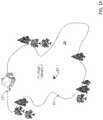
- FIG. 2Bis a schematic top view image of a lawn with UWB beacons showing communication between each beacon, a dock, and the robot,
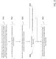
- FIG. 3is a flow chart of a process for initializing and establishing the position of UWB beacons around a lawn
- FIGS. 4A-Fare schematic drawings illustrating a UWB beacon based lawn mowing system initialization process
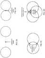
- FIGS. 5A-5Dprovide a schematic drawing illustrating a process for estimating the location of a sensor
- FIG. 6Ais a schematic of a non-smooth path generated based on a path traversed by a human operator along the perimeter of a lawn and around an interior boundary inside the lawn,
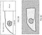
- FIG. 6Bshows a schematic of a lawn with desired mowable and non-mowable zones, including a keep-out zone,
- FIG. 6Cis a schematic of a resulting mowable/non-mowable region determined by the robot for the lawn in FIG. 6B ,
- FIG. 6Dis an initial 2D grid map view indicating interior, boundary, and exterior cells in response to the human operator performing a push/pull action to determine the lawn perimeter
- FIG. 6Eis the map of FIG. 6D after selection of only exterior edge boundary cells
- FIG. 6Fis the map of FIG. 6E after smoothing with only exterior edge cells indicated as boundary,
- FIG. 7is a flow chart of a method of determining a smoothed exterior boundary
- FIG. 8is a flow chart of a method of determining a smoothed interior boundary
- FIG. 9Ais a schematic showing a “near boundary” or “caution” zone two feet from the boundary
- FIG. 9Bis a flow chart of a process for speed/attitude adjustments performed by the robot while navigating the lawn.
- FIG. 10is a flow chart of an alternative method for determining a smoothed boundary.
- an autonomous robot lawnmower 10is configured to mow a lawn 20 .
- the autonomous robot lawnmower 10moves about the lawn 20 and cuts grass 22 as it is traversing the lawn 20 .
- the robot lawnmower 10includes a body 100 , a surface treater 200 secured to the body 100 , a drive system 400 including at least one motorized wheel 410 , and a sensor system 300 having at least one surface sensor 310 carried by the body 100 and responsive to at least one surface characteristic.
- the drive system 400is carried by the body 100 and configured to maneuver the robot lawnmower 10 across lawn 20 while following at least one surface characteristic.
- surface treater 200includes a reciprocating symmetrical grass cutter floating on a following wheel 410 .
- the wheelcan be a continuous track, or tank tread.
- surface treater 200may comprise a rotary cutter, a spreader, or a gatherer.
- a grass comber 510may also be carried by the body 100 .
- the robot body 100supports a power source 106 (e.g., a battery) for powering any electrical components of the robot lawnmower 10 , including the drive system 400 .
- a wireless operator feedback unit 700sends a signal to an emitter/receiver 151 on the robot lawnmower 10 that is in communication with a controller 150 .
- the drive system 400is configured to follow the signal received from the operator feedback unit 700 .
- the robot lawnmower 10may be docked at a base station or dock 12 .
- the dock 12includes a charging system for changing a battery 160 housed by the robot body 100 .
- An important step in the use of the robot lawnmower 10is defining a perimeter 21 of the lawn 20 to be mowed.
- autonomous use of the robot lawnmower 10can only be executed once a perimeter or boundary has been determined and stored in non-transitory memory of the robot lawnmower 10 .
- a human operatormanually defines a perimeter 21 by pushing the robot 10 using a handle 116 attached to the robot body 100 , as shown in FIG. 1B . Once the perimeter has been taught, the robot can navigate the lawn/area to be cut without further human intervention.
- a human operatormanually guides the robot lawnmower 10 to establish the perimeter 21 of the lawn 20 .
- Determining the perimeter 21can include guiding the robot lawnmower 10 with a push bar or handle 116 attached to the body 100 .
- the push bar 116may be detachable from or stowable on the robot body 100 .
- the push bar 116includes a switch, speed setting, or joystick to advance and steer the robot lawnmower 10 .
- the push bar 116includes one or more pressure or strain sensors, monitored by the robot lawnmower 10 to move or steer in a direction of pressure (e.g., two sensors monitoring left-right pressure or bar displacement to turn the robot lawnmower 10 ).
- the push bar 116includes a dead man or kill switch 117 A in communication with the drive system 400 to turn off the robot lawnmower 10 .
- the switch 117 Amay be configured as a dead man switch to turn off the robot lawnmower 10 when an operator of the push bar 116 ceases to use, or no longer maintains contact with, the push bar 116 .
- the switch 117 Amay be configured act as a kill switch when the push bar 116 is stowed, allowing a user to turn off the robot lawnmower 10 .
- the dead man or kill switch 117 Amay include a capacitive sensor or a lever bar.
- the push bar 116includes a clutch 117 B to engage/disengage the drive system 400 .
- the robot lawnmower 10may be capable of operating at a faster speed while manually operated by the push bar 116 .
- the robot lawnmower 10may operate at an autonomous speed of about 0.5 m/sec and a manual speed greeter than 0.5 m/sec (including a “turbo” speed actuatable to 120-150% of normal speed).
- the push bar 116may be foldable or detachable during the robot's autonomous lawn mowing.
- the push bar 116can be configured as one of a pull bar, pull leash, rigid handle, or foldable handle.
- the push bar 116can be stowed on or in the robot body 100 .
- the robot lawnmower 10completes a teaching phase.
- the human operatormay pilot the robot lawnmower 10 in a manner that requires correction, thus putting the robot lawnmower 10 in an unteachable state.
- the robot lawnmower 10alerts the operator (e.g., via operator feedback unit 700 such as a display on a mobile device or a display integrated in a handle 116 ) to change a direction or speed of the robot lawnmower 10 to enable the robot lawnmower 10 to continue to record the perimeter 21 and/or return to traveling on traversable terrain.
- the robot lawnmower 10may enter the unteachable state when the operator pushes the robot lawnmower 10 into an area of the lawn 20 where the robot lawnmower 10 loses ability to determine its location, when the user is on a second teaching path that varies from a first teaching path, or when the user pushes the robot lawnmower 10 too fast or over terrain that is too bumpy or tilted.
- the operatormay try to push the robot lawnmower 10 between a divot and a rock, causing the robot lawnmower 10 to tilt at an excessive angle (e.g., over 30 degrees).
- the operatormay attempt to teach the robot lawnmower 10 a path that goes through topography that the robot lawnmower 10 cannot traverse in the autonomous mode.
- the robot lawnmower 10alerts the operator (e.g., via the operator feedback unit 700 ) to select a different path.
- the robot lawnmower 10may alert the operator via the operator feedback unit 700 by a visual signal on a display, an audible signal through a speaker, and/or a tactile signal, such a vibration from a vibrational unit of the operator feedback unit 700 .
- operator feedback unit 700includes a speed indicator that will light or flash (green, yellow, red light) when the robot lawnmower 10 is going at a speed greater or lower than a threshold speed.
- boundary markers 805may be placed along the perimeter of the lawn 20 to aid localization of the robot lawnmower 10 .
- boundary markers 805send out a signal that the robot lawnmower interprets to determine its position relative to the boundary marker.
- boundary markers 805are passive. In either case, when the robot lawnmower 10 loses contact with the boundary markers 805 , the robot lawnmower 10 may alert the user to change paths to remain within the confinement of the boundary markers 805 .
- the teaching routinerequires the operator to traverse the perimeter 21 of the lawn 20 a second time (or more). Once the operator completes a first teaching run, completing a closed loop about the perimeter of the area to be mowed, the robot lawnmower 10 may alert the operator that a second run is needed. In one example, the operator hits a STOP button to affirmatively indicate completion of a teaching run around the perimeter 21 of the lawn 20 . In some examples, the robot lawnmower 10 allows the operator to either complete the second teaching run right after the first teaching run or wait until later.
- the robot lawnmower 10alerts the user to the apparent discrepancy and prompts another teaching run to learn the perimeter 21 of the lawn 20 .
- the usermay dock the robot lawnmower 10 in its dock 12 (see FIG. 1A ), allowing the robot lawnmower 10 to recharge before mowing.
- the robot lawnmower 10includes a boundary detection system 800 that includes the emitter/receiver 151 disposed on the robot body 100 and passive boundary markers 805 ( FIG. 2A ).
- the types of passive boundary markers 805may include: LIDAR scan match, passive LIDAR retro-reflectors (beacons) or both of those together.
- the boundary markers 805include: RADAR scan matching (blips), RADAR retro-reflectors or both.
- the boundary markers 805are individually identifiable by adjacent scan match data performed by the emitter/receiver 151 (see FIG. 1B ).
- the robot lawnmower 10can match scans taken at a given time while driving with scans stored in memory that are characteristic of each boundary marker 805 , and the robot lawnmower 10 is thus able to determine its position relative to each of the individually identifiable boundary markers 805 .
- the boundary markers 805includes other individual identification means perceptible to the robot lawnmower 10 , such as a bar code or encoded signal to enable the robot lawnmower 10 to determine its relative position.
- boundary markers 805are placed around the perimeter of the lawn 20 to constrain or influence behavior of the robot lawnmower 10 .
- the boundary markers 805create a virtual wall that constrains the robot lawnmower 10 from going outside the marked boundary (i.e., perimeter 21 ).
- a userplaces the boundary markers 805 at desired positions along the perimeter 21 .
- the boundary markers 805are each within a line of sight of an adjacent boundary marker 805 .
- the boundary markers 805may include a home marker that an operator can place in a position indicating a global origin (e.g., dock 12 or two boundary markers placed side by side). The operator distributes the boundary markers 805 as evenly as possible along the perimeter 21 of the lawn 20 to indicate the confinement area.
- each major corner of perimeter 21is marked by a boundary marker 805 .
- beaconssuch as Ultra-wide Band (UWB) beacons can be placed in the environment, and the robot can use the landmarks to localize its position.
- These beaconscan be placed inside the mowable area (e.g., beacon 810 b ), on the boundary (e.g., beacon 810 a ), or outside the boundary (e.g., beacon 810 c ).
- These beacons 810FIG. 2B ) include UWB transceivers 811 that communicate with each other as well as with a UWB transceiver 11 located on the lawnmower robot 10 .
- Respective UWB transceiversare placed on the robot lawnmower 10 (e.g., the robot lawnmower 10 includes a receiver/emitter 151 communicating with each of the beacons 810 a - c ), each of the beacons 810 a - c , and optionally the dock 12 .
- the robot lawnmower 10communicates with each of the beacons 810 a - c and the dock 12 .
- Each beacon 810 a - ccommunicates with each of the other beacons and the dock 12 .
- ultra-widebandalso known as UWB, ultra-wide band and ultraband
- Ultra-widebandtransmits information spread over a large bandwidth (>500 MHz).
- UWBincludes transmission from an antenna for which the emitted signal bandwidth exceeds the lesser of 500 MHz or 20% of the center frequency.
- UWB beacons 810 a - cwhich include the UWB transceivers 811 a - c ) provides several advantages over other confinement/localization systems. In general, ultra-wideband characteristics are well-suited to short-distance applications.
- Ultra-widebandcan be beneficial in autonomous lawn mowing because the signals can be transmitted past/through obstacles such as bushes or trees and provide precision localization of the lawn mowing robot 10 relative to the UWB beacons 810 a - c .
- UWB transceivers 811 a - cemit an omnidirectional signal so the use of UWB signals can be more resistant to robot orientation than line-of-sight optical systems, such as vision-based or laser-based systems.
- a UWB signalcan pass through small obstacles such as trees and shrubs allowing placement of the UWB beacons in less visible locations about a mowable space (e.g., as shown by the transmission between beacon 810 b and 810 c ).
- UWB signals from UWB beacons 810 a - c positioned about a yardare to be used to determine the autonomous lawn mowing robot's location within the yard, the location of the UWB beacons 810 a - c needs to be established.
- an initialization processis performed upon initial setup of a UWB system. The process is based, in part, on a multidimensional scaling algorithm used to determine the location of the UWB beacons 810 a - c relative to one another, which in turn can be used to establish the location of the robot 10 relative to the beacons.
- a home owner or other person installing the UWB beacons 810 a - cis not required to place the UWB beacons 810 a - c at particular locations because the system automatically determines the locations of the UWB beacons 810 a - c upon initialization.
- This flexibility in positioning of the UWB beacons 810 a - cis believed to provide the advantage of simplifying the installation and setup procedure for the autonomous lawn mowing robot system.
- the UWB beacons 810 a - ccan be lower to the ground than in certain line-of-sight based systems because the robot 10 does not need to align (e.g., in a line-of-sight arrangement) with the beacon in order for a signal to be received from the beacon.
- a calibration or confirmation processcan be performed to confirm that the UWB beacons 810 a - c are still in their expected, previously determined locations.
- a UWB beacon based lawn mowing system initialization processbegins with a plurality of UWB beacons 862 a - e that each include a UWB transceiver placed around a mowable space 870 ( FIG. 4A ).
- the UWB transceiverseach have a unique identifier included in transmissions from the UWB transceiver to identify the source of the transmission.
- the robot lawnmower 860includes a UWB transceiver which allows the robot lawnmower 860 to communicate with the UWB transceivers in the UWB beacons 862 a - e .
- the UWB beacons 862 a - e placed around a mowable space 870are generally non-mobile and are intended to remain stationary once placed around the mowable space 870 .
- the UWB beaconscan be positioned inside the mowable space 870 , outside the mowable space 870 , and/or on the border between the two. Additionally, due to the omnidirectional nature of the signals generated by the UWB transceivers in the UWB beacons 862 a - e , the robot can be placed inside or outside of the boundary at startup.
- the initialization processincludes gathering/obtaining information about the distances between the UWB beacons positioned around the mowable space (step 850 ). More particularly, one UWB transceiver (e.g., the transceiver located on the robot 860 or on the dock) sends a request to each of the other UWB transceivers for information about the distance between itself and each of the other UWB transceivers. This information can include time-of-flight information or other data that can be used to determine distance. For example, in the examples shown in FIGS.
- the UWB transceiver in UWB beacon 862 aupon receiving the request from the UWB transceiver on the robot 860 , the UWB transceiver in UWB beacon 862 a sends a signal to the UWB transceivers in UWB beacons 862 b , 862 c , 862 d and 862 e .
- the UWB transceiver in beacon 862 areceives, from the UWB transceivers in UWB beacons 862 b , 862 c , 862 d and 862 e , time-of-flight information and the associated unique identifier for the UWB transceiver ( FIG. 4A ).
- the UWB transceiver in beacon 862 bupon receiving the request from the UWB transceiver on the robot 860 , the UWB transceiver in beacon 862 b sends a signal to the UWB transceivers in UWB beacons 862 a , 862 c , 862 d and 862 e . In response, the UWB transceiver in beacon 862 b receives, from the UWB transceivers in UWB beacons 862 a , 862 c , 862 d and 862 e , time-of-flight information and the unique identifier for the associated UWB transceiver ( FIG. 4B ).
- beacons 862 c , 862 d , and 862 eSimilar gathering of information occurs for beacons 862 c , 862 d , and 862 e ( FIG. 4C ). This information is sent from the individual UWB transceivers to the UWB transceiver that issued the request for information (e.g., the transceiver located on the robot 860 or on the dock).
- a processor in the robot lawnmower 10uses a multi-dimensional scaling algorithm to determine the relative position (e.g., the x-y position relative to a global origin such as the dock position) of the UWB beacons ( 852 , FIG. 4D ).
- multidimensional scalingis a way of visualizing the level of similarity of individual cases of a dataset. It refers to a set of related ordination techniques used in information visualization, in particular to display the information contained in a distance matrix.
- An MDS algorithmaims to place each object in N-dimensional space such that the between-object distances are preserved as well as possible.
- Each objectis then assigned coordinates in each of the N dimensions.
- the relative positions of the UWB beaconse.g., beacons 862 a , 862 b , 862 c , 862 d and 862 e ) determined using the MDS algorithm are stored in a memory.
- the use of a multi-dimensional scaling (MDS) algorithmcan generate a beacon map that is a mirror image of the actual beacon layout. If a mirror image of the actual beacon layout were used during navigation, this would result in the robot not turning in the intended direction when trying to face another point in space.
- the autonomous lawn mowing robot 860is moved in an orientation determination sequence (step 854 ). The system then determines whether the UWB beacon locations are mirrored (step 856 ) and if so, reassigns headings to the UWB beacon locations to correct the orientation (step 858 ).
- the robotstores its initial point and drives forward for a short distance (e.g., 15-30 cm) to a second point.
- This driving forwardestablishes a y-axis used to reassign beacon locations if the beacon map is determined to be a mirror image of the actual beacon layout.
- the robotturns roughly 90 degrees to the left and drives forward another short distance (e.g., 15-30 cm) as shown in path 872 in FIG. 4E .
- the processorthen computes the difference in bearing between the vector connecting the initial point to the second point and the vector connecting the second point to the third point. If the beacon locations are correct, this value will be close to 90 degrees.
- beacon locationsare mirrored, the value will be close to minus 90 degrees, and the robot will reassign/reinterpret (e.g., flip) the beacon coordinates across the y-axis and thereby properly determine its pose.
- reassign/reinterprete.g., flip
- the systemlocalizes the autonomous lawn mowing robot 860 by trilaterating based on received time-of-flight information (range) from each of the UWB transceivers ( FIG. 4F ).
- trilaterationis the process of determining absolute or relative locations of points by measurement of distances, using the geometry of circles, spheres or triangles.
- the location of a sensorcan be determined by measuring the range to at least three landmarks, drawing a circle of the corresponding radius around each landmark, and determining the point at which these range circles intersect. With perfect sensing, all of the circles would intersect at one point, and this location could be determined using a closed-form solution. However, all sensors have some noise, so these circles are unlikely to intersect at one point, and some means is necessary to estimate the sensor position based on multiple intersections between range circles.
- a least squares algorithmcan be used to minimize the sum of squared error between the sensed ranges and the position estimate.
- the robot's locationcan be determined using a technique referred to herein as minimum-distance intersection set trilateration (MIST).
- MISTis a technique for estimating the location of a sensor based on noisy range data from a set of fixed beacons at known locations. Like other trilateration techniques, MIST uses the intersections between circles corresponding to range readings to determine the location of the sensor.
- the time-of-flight measurementsare used to determine a circle of possible locations around each of the beacons where the radius of the circle is based on the distance between the UWB transceiver in the UWB beacon and the UWB transceiver in the robot. For every pair of range circles, there may be zero, one, or two intersection points.
- MISTworks by examining all of the feasible sets of intersection points and selecting the set with the minimum total distance between points.
- a feasible setconsists of a candidate point for each pair of range circles. There are three possible cases for each pair of circles.
- the candidate pointis set to the midpoint in the line connecting the closest points on the two range circles.
- the circlesintersect at one point.
- the candidate pointis set to the single intersection point.
- MISTestimates the sensor position to be the centroid of the candidate points within this set.
- the small circlesmark candidate points (e.g., the intersection locations for pairs of circles).
- the filled circlesare the candidate points in the feasible set with the minimum total inter-point distance.
- the unfilled circlesare the candidate points that are not in this set.
- the crosshairsmark the centroid of the points in the minimum distance intersection set and correspond to the estimated location of the sensor.
- one or more of the UWB beaconsmay be in an isolated location and therefore it may be challenging to locate the UWB beacon relative to the other UWB beacons.
- one beaconcould be placed in a side-yard where the house prohibits communication with some of the other UWB beacons.
- the initially determined location for the beaconmay have a lower confidence since the location determination is based on communications between the isolated beacon and only a subset of the other beacons positioned about the yard. If a calculated confidence value is below a threshold confidence value, the system could request that the user move the mower (which itself includes a UWB transceiver) to a location where the mower can communicate with both the isolated beacon and a plurality of other beacons.
- the systemcan then use the UWB transceiver on the robot to help position the isolated UWB beacon (e.g., using a similar process to that described above).
- the autonomous robotcan be moved and the isolated beacon's location can be stored relative to the other beacons.
- the human operatorwill walk the robot around the lawn 20 .
- the human operatormay experience difficulty manually navigating the robot lawnmower 10 around the perimeter 21 due to e.g., bumpy terrain or an obstacle blocking the path of the robot lawnmower 10 .
- the usermay generate non-smooth paths. For example, a user may perform jagged or staggered movements in order to navigate about the perimeter 21 during guidance of the robot lawnmower 10 .
- the initially established lawn outlinee.g., the actual teaching path 23 traversed by the robot
- an algorithmwill select the positions navigated by the robot lawnmower 10 during teaching mode. Once the rough lawn boundary is determined, the algorithm will perform edge selection and smoothing functions on the initial boundary data (or on a subset of the collected data).
- the edge selection functionfinds the outermost edge of the mowable area, maximizing the area to be mowed, and combined with the smoothing function results in a continuous boundary that the robot lawnmower 10 can navigate autonomously subsequent to the teaching mode.
- This process for determining and smoothing the boundary of the mowable spacecan be used with various beacon-based localization systems where distance is measured from the mobile asset (robot) to the beacons. Such technologies include but are not limited to time-of-flight (TOF), time distance of arrival (TDOA), or signal strength based systems.
- a userwill attempt to navigate the robot around perimeter 21 of the lawn 20 , illustrated by the solid boundary line, but in fact navigate along the actual teaching path 23 (illustrated by the dashed boundary line) which may be non-smooth, and can include irregularities.
- the robot lawnmower 10will determine and store its position at all times relative to the beacons 810 , via a data processing unit.
- This data processing unitmay be the controller 150 mounted on the robot lawnmower (see FIG. 1B ), or may be a separate data processing unit.
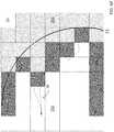
- the data processing unitgenerates a 2D grid or matrix 25 of cells to represent the lawn, and as the robot lawnmower 10 determines its position relative to the beacons 810 , the data processing unit determines and saves the coordinates of each cell containing the robot lawnmower 10 during its motion.
- Each cell in grid 25can have one of three possible mowing-area values indicating whether the cell is understood to be outside the perimeter 21 or NONMOWABLE, inside the perimeter 21 or MOWABLE, or on the area perimeter 21 BOUNDARY.
- FIG. 6Arepresentative NONMOWABLE cells 25 A, MOWABLE cells 25 B, and BOUNDARY cells 25 C are illustrated.
- Each cell of the grid 25can be assigned (x, y) coordinates based on a chosen origin or reference position (0, 0) cell. Each cell can represent a square area, with each cell having a pre-determined length and width (e.g., between 5-20 cm, between 8-12 cm, about 10 cm).
- the grid 25can be a grid of cells, each 10 cm ⁇ 10 cm.
- the robot lawnmower 10stores the (x, y) coordinates of each cell traversed by the robot lawnmower along the actual teaching path 23 traveled during the teaching mode.
- the robot lawnmower 10can mark the actual teaching path 23 as a simple line tracing the path of the robot 10 through single cells as shown in FIG. 6A .
- the robotcan mark all cells under the footprint of the robot as BOUNDARY cells 25 C.
- the values of all cellsare initialized to NONMOWABLE.
- the operatorpresses the start button to start the teach process and then drives around the perimeter 21 of the mowing area.
- the values of all cells along its actual teaching path 23are set to BOUNDARY, the location of the cells being determined by the distance to the beacons 810 .
- the operatorpresses a button to end the teaching process.
- the operatorpositions the robot lawnmower 10 anywhere within the mowable area of lawn 20 , for example at position P, and presses a button, indicating to the robot lawnmower 10 that it is inside the perimeter.
- the systemperforms a flood fill to set the values of all cells inside perimeter 21 defined by the BOUNDARY cells 25 C to mark them as MOWABLE cells 25 B corresponding to areas to be mowed.
- keep-out zonescan also be trained using a method similar to that for teaching the boundary. For example, to create a keep-out zone around a tree, the user can move the robot to a point on the boundary of the tree; put the robot into teach mode; push the robot around the tree; and then take the robot out teach mode. All of the cells traversed by the robot will be marked as BOUNDARY cells (e.g., as indicated by thick line in FIG. 6C ), and the area inside this closed boundary will remain NONMOWABLE (e.g., the solid area) and the area inside the perimeter of the lawn and outside of the closed boundary will remain MOWABLE (e.g., as indicated by the hatched area in FIG. 6C ).
- BOUNDARY cellse.g., as indicated by thick line in FIG. 6C
- FIG. 6Eshows a close-up of a portion of the perimeter 21 containing a portion of an actual teaching path 23 navigated by the human operator and lawnmower robot lawnmower 10 during the teaching mode.
- Actual teaching path 23includes non-smooth characteristics, such as a jag 28 , resulting from where the human operator, for example, turned the robot lawnmower 10 and then partially retraced the path by pushing the robot lawnmower 10 backwards.
- NONMOWABLE cells 25 A, MOWABLE cells 25 B and BOUNDARY cells 25 Care shown in hatch, white, and grey, respectively.
- FIG. 6Fshows the grid map after performing an boundary smoothing function, in which the controller 150 has selected a subset of the initial BOUNDARY cell blocks by re-labeling any BOUNDARY cell that is not adjacent to both a MOWABLE and a NONMOWABLE cell as MOWABLE.
- the systemcan re-label some of the previous BOUNDARY cells 25 C as MOWABLE cells 25 B, in order to determine the outermost edges of the path to be followed by the robot lawnmower 10 when it navigates the lawn 20 autonomously at a later time.
- the controller 150selects all the BOUNDARY cells 25 C and computes the distance between each BOUNDARY cell 25 C to the origin (0, 0) cell.
- the origin callcan be the interior position cell P shown in FIG. 6A .
- the controllercan calculate this distance given the known (x, y) coordinates determined for each BOUNDARY cell 25 C.
- the controllercompares the distance of each BOUNDARY cell 25 C to select the BOUNDARY 25 C cells most distant from the origin P and determines a single-cell line of cells representing the outermost BOUNDARY cells 25 C.
- the controller 150examines the mowing-area value of each cell adjacent to each cell labeled BOUNDARY. Any BOUNDARY cell 25 C that is in an adjacent position to more than one other BOUNDARY cell 25 C is then examined to determine which cell 25 C is furthest from the origin P and is thus the outermost limit to be mowed.
- the controllerselects only the outermost (e.g., farthest away) cells.
- outermost cellse.g., farthest away
- the systemcan identify a gap, or break in the contiguous BOUNDARY cells.
- the controller 150can search for such discontinuities, by searching for BOUNDARY cells that are not adjacent to or corner to corner with any other BOUNDARY cell.
- the controller 150can then select MOWABLE cells adjacent to the discontinuous BOUNDARY cells.
- the controller 150can interpolate between the x, y values of the discontinuous BOUNDARY cells, and reassign all cells lying on the line between the discontinuous cells as BOUNDARY cells.
- the controller 150can alter a portion of the stored perimeter data set corresponding to a perimeter path segment defining an interior angle less than 135 degrees, to define a smoothed boundary.
- the interior anglecan be less than 90 degrees, or less than 45 degrees.
- inside boundary 29circumscribes a pond.
- the usernavigates the robot lawnmower 10 along inside boundary 29 and then positions the robot lawnmower at a final position such as position P. This indicates that the lawnmower robot lawnmower 10 is located on MOWABLE area.
- the controller 150assigns the areas inside the inside boundary 29 as NOT MOWABLE, and outside actual teaching path 23 , which is also NOT MOWABLE. Referring to FIG.
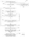
- a method 1000 for teaching a robot lawnmower 10 the perimeter of an area within the lawnallows the robot to autonomously mow the lawn 20 at a later time.
- the methodbegins when the robot lawnmower 10 enters boundary determination mode (step 1001 ).
- the robot lawnmower 10first monitors if teach mode can be used by checking if the handle 116 is attached (step 1002 ). If the robot determines that the handle 116 is not attached, the robot will prompt the user to attach the handle 116 (by, e.g., beeping, or flashing a light on the operator feedback unit). Once the robot lawnmower has determined that handle 116 is attached, the emitter communicates with the beacons in a UWB calibration sequence (as described above with respect to FIG.
- the robot lawnmowerdetermines its initial location relative to the beacons and the dock, and initializes a virtual 2D grid of cells around its initial location, to represent lawn 20 (step 1010 ).
- the robot lawnmower 10may determine the distance to the farthest beacon 810 , and build a grid centered on the initial location, and extending on all sides by the distance to the farthest beacon.
- the robot lawnmoweris ready to begin teachable mode motion by the operator.
- the robot lawnmowerprompts the operator to push the robot lawnmower around the perimeter of the lawn (step 1012 ).
- the controlleris in communication with the beacons and collects location data (step 1014 ).
- the robotcan collect time of flight data from each of the UWB beacons and use the data to determine the location (e.g., by triangulation).
- Each cell of the 2D grid corresponding to a detected position of the robot during this motionis set to a value marking the cell as a boundary cell (step 1016 ).
- the robot lawnmowercontinuously checks if it has received operator input indicating completion, or whether a length of non-mobile time greater than a stored threshold time has elapsed (step 1018 ). If not, the robot lawnmower continues collecting location data and marking the cells corresponding to those locations as boundary cells.
- the operatormay optionally define keep-out zones around any interior regions by pushing the mower around the internal boundary of these regions.
- the robot lawnmowerprompts the operator to move the robot lawnmower 10 to a mowable, interior area of the lawn (i.e., the space to be mowed, step 1020 ), and then determines and saves the position of this initial interior position.
- the controllerthen identifies all boundary cells that are not adjacent to both mowable and non-mowable cells and relabels boundary cells that are adjacent to mowable or another boundary cell and not adjacent to non-mowable as mowable (step 1022 ) to calculate a final, smoothed boundary.
- the systemretains only the outermost cell as a boundary cell (e.g., the cell touching the non-mowable space) and relabels the other cells as mowable.
- the re-labeling processselects the cells that are adjacent to only mowable cells and boundary cells and relabels those cells as mowable.
- the controlleruses a filling function to assign all locations inside the calculated smoothed boundary as inside/mowable area (step 1024 ).
- the controllerselects the outermost locations of the boundary cells in the map and performs the edge selection and smoothing operation on selected cells to calculate a final, smoothed boundary.
- the controlleruses a filling function to assign all locations inside the calculated smoothed boundary as inside/mowable area.
- a method 2000is shown for determining a boundary about an interior area not to be mowed (e.g., boundary 29 in FIG. 6A ).
- the robot lawnmower 10enters boundary determination mode (step 2001 ).
- the robotfirst checks if calculation of the outside perimeter boundary is complete (step 2002 ), and if not instructs the operator to complete the perimeter determination as described above (step 2004 ).
- the robotdetermines whether all keep out zones (e.g., areas inside the defined perimeter of the lawn that should not be mowed such as flower beds, swing sets, ponds, etc.) have been defined (step 2003 ).
- the robotcan determine whether all keep out zones have been defined by generating a prompt for a user to indicate whether the zones have been defined and receiving a response from the user indicative of their completion/non-completion. Is all keep out zones have been defined, the system proceeds to smoothing the boundaries of the keep out zones (step 2014 ). If all keep out zones have not been defined, the robot prompts the operator to push the robot lawnmower around the edge of any interior boundaries, if desired (step 2006 ). While the user pushes the robot lawnmower, the controller is in communication with, or otherwise monitors the location of, the beacons or boundary markers, and collects location data (step 2008 ).
- each cell of the 2D grid corresponding to a location of the robot during this routineis set to BOUNDARY (step 2010 ).
- the robotcontinuously checks if it has received operator input indicating completion or whether a length of non-mobile time greater than a stored threshold time has elapsed (step 2012 ). If not, the robot lawnmower continues collecting location data and marking the cells of grid 25 corresponding to robot lawnmower's position as BOUNDARY cells.
- the robot lawnmowerthen prompts the operator to move to a mowable area of the lawn (step 2014 ) within the outside perimeter border and not inside any of the (optional) keep-out zones, and records the pose of the robot in the mowable space (step 2016 ).
- the systemthen uses a flood fill to set all cells within the boundary to NON-MOWABLE (e.g., all of the cells that are within the keep out zone) (step 2018 ).
- the systemre-labels boundary cells for keep out perimeters that are adjacent to mowable and not adjacent to both mowable and non-mowable (keep out zone) to mowable (step 2020 ).
- the systemcan perform the above-described smoothing operation on the entire grid map including both the interior boundaries of the keep out zones and the external perimeter in a single process.
- the systemuses a flood fill to fill all areas indicated by the robot pose in the mowable space. This flood fill sets all grid locations inside of the external perimeter of the lawn and outside of the defined keep out zones to MOWABLE.
- the systemthen performs a smoothing algorithm on both the perimeter of the lawn and the perimeters of the keep out zones. For example, the system can set all boundary cells that are not adjacent to both MOWABLE and NONMOWABLE to MOWABLE such that a boundary is generated where each boundary cell contacts both MOWABLE and NONMOWABLE space.
- Control of the robot lawnmower 10 during autonomous operationincludes allowing the robot lawnmower to traverse the lawn 20 within the area delineated by the determined boundaries.
- Operation of the drive systemcan include a slow-down mode initiated when the robot lawnmower 10 approaches a boundary, to help prevent the robot lawnmower 10 accidentally rolling past the boundary. Additionally, a slow-down mode can also be implemented when the robot lawnmower 10 approaches a boundary marker 805 .
- the robot controllerdetermines a “near boundary” 31 equidistant from and inside the previously determined final smoothed outer boundary 27 .
- the controller 150selects cells close to the BOUNDARY cells. For example, the controller 150 can select all MOWABLE cells that are adjacent to a BOUNDARY cell, and re-label the selected cells which are close to and touching the boundary as being NEAR BOUNDARY cells.
- the controllercan select all MOWABLE cells that are adjacent to a NEAR BOUNDARY cell, and re-label the newly selected sells as NEAR BOUNDARY.
- This processcan be completed until all cells previously marked MOWABLE that are within a fixed distance of the boundary are relabeled NEAR BOUNDARY. For example, all MOWABLE cells that are within, 0.35 m (2 feet) of the boundary 27 can be labeled as being NEAR BOUNDARY cells, or part of a caution zone. The remaining interior cells are in the safe zone and remain labeled as MOWABLE cells.
- This grid cell labelingeffectively defines the near boundary line 31 , equidistant at all or nearly all points from the actual outside boundary 27 .
- the near boundary line 31can also be smoothed, as described above with respect to the actual boundary line.
- a similar method of creating a NEAR BOUNDARY or caution zonecan be employed for interior boundaries as well.
- FIG. 9BA method of autonomous control as the robot lawnmower navigates the lawn is shown in FIG. 9B .
- the robot lawnmowercontinuously collects its location data and constructs a virtual map of labeled grid cells as described above (steps 3002 and 3004 ). If the robot determines that it is located in a MOWABLE or safe cell, the robot lawnmower continues driving forward at its current speed (step 3006 ) and heading (step 3008 ). When the robot is in this safe zone, it drives at full autonomous speed (0.5 m/s). If the robot lawnmower 10 determines that is in a NEAR BOUNDARY cell indicating the caution zone, it slows (to, e.g., 0.15 m/s), in step 3010 .
- the two speedscan be determined by the update rate of the localization algorithm and the response time of the low-level motor control.
- a ratio of the full autonomous speed to the near boundary speedcan be between about 5:1 and about 2:1, e.g., about 5:1, about 4:1, about 3:1, about 2:1.
- the targetis selected so that it is at least a minimum distance from the nearest BOUNDARY cell and so that the path from the robot to the target passes through no more than a specified number of BOUNDARY or NON-MOWABLE cells.
- the robotthen turns to face the target and resumes forward motion.
- the resumed motionresumes with the robot lawnmower 10 following along a path close to the boundary, e.g., at a constant distance from the boundary.
- the robot lawnmower 10can follow the boundary until a complete perimeter is mowed.
- the robot lawnmower 10then may move a constant distance inside the MOWABLE area and complete another circuit, continuing on decreasing circuits until the lawn 20 is mowed.
- the robotmay mow a complete perimeter, and then follow a series of parallel, adjacent lines until the MOWABLE area inside the boundary is completely traversed.
- a method of smoothing the path of the robot lawnmower for later traversing of a boundarycan use the suspension of teaching mode feature discussed above. For example, when the user pulls the robot backwards to reposition the robot during teaching, a jagged path (such as jag 28 in FIG. 6E ) results. As described above, this can place the robot lawnmower in an unteachable state, where teaching mode is automatically suspended. Teaching mode resumes when the robot lawnmower 10 detects it is moving forward again (within a threshold period of time).
- FIG. 10describes an implementation of a method 4000 for teaching a robot lawnmower the perimeter of an area within the lawn allows the robot to autonomously mow the lawn at a later time which uses this suspension of teach mode.
- the robot lawnmower 10follows steps similar to those described in FIG. 7 , checking if handle 116 is attached and, if it determines that the handle 116 is not attached, prompting the user to attach the handle 116 (by, e.g., beeping, or flashing a light on the operator feedback unit). Once the robot lawnmower has determined that handle 116 is attached, the emitter communicates with the beacons or boundary markers, and determines if the beacons are UWB beacons. If so, the UWB calibration sequence (as described above with respect to FIG. 2B ) is executed.
- the robot lawnmowerdetermines its initial location relative to the beacons 810 and the dock 12 , and initializes a virtual 2D grid of cells around its initial location, to represent lawn (step 4010 ).
- the robot lawnmower 10is ready to begin teachable mode motion by the operator and prompts the operator to push the robot lawnmower 10 around the perimeter 21 of the lawn 20 (step 4012 ).
- the controller 150is in communication with the beacons 810 and collects location data (step 4014 ).
- Each cell of the 2D grid corresponding to a detected position of the robot during this motionis set to a value marking it as a BOUNDARY cell (step 4016 ).
- the robotcontinuously checks if it is moving forward (step 4017 ). If so, the robot continues to collect location data and set each cell traversed to boundary (steps 4014 and 4016 ). If not, the robot checks whether it has received operator input indicating completion, or whether a length of non-mobile time greater than a stored threshold time has elapsed (step 4018 ) and again checks whether the robot is moving forward (step 4017 ). If so, the robot resumes collecting location data.
- the robotdetermines (step 4018 ) whether the operator has indicated completion (or that time has run out), in which case the robot lawnmower 10 determines that the mapping of the perimeter 21 is complete and prompts the operator to move to a mowable, interior area of the lawn (i.e., the space to be mowed, step 4020 ).
- the controllerselects the outermost locations of the boundary cells in the map (step 4022 ) and performs the smoothing operation on selected cells (step 4024 ) to calculate a final, smoothed boundary.
- the controlleruses a filling function to assign all locations inside the calculated boundary as inside/mowable area (step 4026 ).
- the grid established with MOWABLE, NONMOWABLE, and BOUNDARY cellscan additionally be used to determine where the mobile robot should travel while mowing the lawn.
- the systemcan record information about coverage-type states for the robot. For example, the system can keep track of the number of time the robot has visited the cell (to mow it) during a particular run or across multiple runs. For example, the system could determine a pose of the robot and identify the associated location on the grid. Information associated with that grid location could then be updated to indicate that the robot had mowed the location.
- the robotcould then identify cells that had either not been mowed during the current run or that had been mowed less frequently over a series of past mowing runs (e.g., over the past 3 runs) and mow those areas prior to mowing other areas. This would be helpful for covering areas adequately before moving to other areas.
- beacon-based localization systemswhere distance is measured from the mobile asset (robot) to the beacons.
- technologiesinclude but are not limited to time-of-flight (TOF), time distance of arrival (TDOA), or signal strength based systems.
Landscapes
- Engineering & Computer Science (AREA)
- Physics & Mathematics (AREA)
- Automation & Control Theory (AREA)
- Aviation & Aerospace Engineering (AREA)
- General Physics & Mathematics (AREA)
- Remote Sensing (AREA)
- Radar, Positioning & Navigation (AREA)
- Life Sciences & Earth Sciences (AREA)
- Environmental Sciences (AREA)
- Electromagnetism (AREA)
- Optics & Photonics (AREA)
- Soil Sciences (AREA)
- Mechanical Engineering (AREA)
- Control Of Position, Course, Altitude, Or Attitude Of Moving Bodies (AREA)
- Guiding Agricultural Machines (AREA)
- Harvester Elements (AREA)
Abstract
Description
Claims (14)
Priority Applications (2)
| Application Number | Priority Date | Filing Date | Title |
|---|---|---|---|
| US15/850,413US10750667B2 (en) | 2014-10-10 | 2017-12-21 | Robotic lawn mowing boundary determination |
| US16/999,373US11452257B2 (en) | 2014-10-10 | 2020-08-21 | Robotic lawn mowing boundary determination |
Applications Claiming Priority (3)
| Application Number | Priority Date | Filing Date | Title |
|---|---|---|---|
| US14/512,098US9516806B2 (en) | 2014-10-10 | 2014-10-10 | Robotic lawn mowing boundary determination |
| US15/371,618US9854737B2 (en) | 2014-10-10 | 2016-12-07 | Robotic lawn mowing boundary determination |
| US15/850,413US10750667B2 (en) | 2014-10-10 | 2017-12-21 | Robotic lawn mowing boundary determination |
Related Parent Applications (1)
| Application Number | Title | Priority Date | Filing Date |
|---|---|---|---|
| US15/371,618ContinuationUS9854737B2 (en) | 2014-10-10 | 2016-12-07 | Robotic lawn mowing boundary determination |
Related Child Applications (1)
| Application Number | Title | Priority Date | Filing Date |
|---|---|---|---|
| US16/999,373ContinuationUS11452257B2 (en) | 2014-10-10 | 2020-08-21 | Robotic lawn mowing boundary determination |
Publications (2)
| Publication Number | Publication Date |
|---|---|
| US20180168097A1 US20180168097A1 (en) | 2018-06-21 |
| US10750667B2true US10750667B2 (en) | 2020-08-25 |
Family
ID=54256830
Family Applications (4)
| Application Number | Title | Priority Date | Filing Date |
|---|---|---|---|
| US14/512,098Active2035-01-28US9516806B2 (en) | 2014-10-10 | 2014-10-10 | Robotic lawn mowing boundary determination |
| US15/371,618ActiveUS9854737B2 (en) | 2014-10-10 | 2016-12-07 | Robotic lawn mowing boundary determination |
| US15/850,413Active2035-04-29US10750667B2 (en) | 2014-10-10 | 2017-12-21 | Robotic lawn mowing boundary determination |
| US16/999,373Active2035-07-16US11452257B2 (en) | 2014-10-10 | 2020-08-21 | Robotic lawn mowing boundary determination |
Family Applications Before (2)
| Application Number | Title | Priority Date | Filing Date |
|---|---|---|---|
| US14/512,098Active2035-01-28US9516806B2 (en) | 2014-10-10 | 2014-10-10 | Robotic lawn mowing boundary determination |
| US15/371,618ActiveUS9854737B2 (en) | 2014-10-10 | 2016-12-07 | Robotic lawn mowing boundary determination |
Family Applications After (1)
| Application Number | Title | Priority Date | Filing Date |
|---|---|---|---|
| US16/999,373Active2035-07-16US11452257B2 (en) | 2014-10-10 | 2020-08-21 | Robotic lawn mowing boundary determination |
Country Status (8)
| Country | Link |
|---|---|
| US (4) | US9516806B2 (en) |
| EP (1) | EP3203825B1 (en) |
| JP (2) | JP6679506B2 (en) |
| CN (1) | CN106489103B (en) |
| AU (1) | AU2015328636B2 (en) |
| CA (1) | CA2954200A1 (en) |
| IL (1) | IL249588B (en) |
| WO (1) | WO2016057185A1 (en) |
Cited By (5)
| Publication number | Priority date | Publication date | Assignee | Title |
|---|---|---|---|---|
| US11452257B2 (en) | 2014-10-10 | 2022-09-27 | Irobot Corporation | Robotic lawn mowing boundary determination |
| US12296694B2 (en) | 2021-03-10 | 2025-05-13 | Techtronic Cordless Gp | Lawnmowers |
| US12369509B2 (en) | 2022-07-19 | 2025-07-29 | Techtronic Cordless Gp | Display for controlling robotic tool |
| US12425197B2 (en) | 2022-07-29 | 2025-09-23 | Techtronic Cordless Gp | Generation of a cryptography key for a robotic garden tool |
| US12443180B2 (en) | 2022-11-09 | 2025-10-14 | Techtronic Cordless Gp | Robotic lawn mowers |
Families Citing this family (161)
| Publication number | Priority date | Publication date | Assignee | Title |
|---|---|---|---|---|
| US11048268B2 (en)* | 2011-08-11 | 2021-06-29 | Chien Ouyang | Mapping and tracking system for robots |
| US20170325400A1 (en)* | 2012-11-12 | 2017-11-16 | Ariel Scientific Innovations Ltd | Method for navigation and joint coordination of automated devices |
| CN105446350B (en)* | 2014-09-26 | 2018-05-29 | 科沃斯机器人股份有限公司 | Self-movement robot moves boundary demarcation method |
| US10579066B1 (en)* | 2015-03-30 | 2020-03-03 | AI Incorporated | System and method for establishing virtual boundaries for robotic devices |
| US11347239B1 (en) | 2014-10-01 | 2022-05-31 | AI Incorporated | System and method for establishing virtual boundaries for robotic devices |
| US10188029B1 (en)* | 2014-10-20 | 2019-01-29 | Hydro-Gear Limited Partnership | Method of generating a three-dimensional map of a lawn and its use to improve mowing efficiency |
| US9773392B2 (en)* | 2014-10-27 | 2017-09-26 | Numerex Corp. | Offender monitor with managed rate of location reading |
| JP2016114984A (en)* | 2014-12-11 | 2016-06-23 | 福田 敏男 | Work vehicle |
| EP3470950A1 (en)* | 2014-12-17 | 2019-04-17 | Husqvarna Ab | Boundary learning robotic vehicle |
| WO2016098050A1 (en) | 2014-12-17 | 2016-06-23 | Husqvarna Ab | Multi-sensor, autonomous robotic vehicle with mapping capability |
| WO2016103067A1 (en)* | 2014-12-22 | 2016-06-30 | Husqvarna Ab | Garden mapping and planning via robotic vehicle |
| US9538702B2 (en)* | 2014-12-22 | 2017-01-10 | Irobot Corporation | Robotic mowing of separated lawn areas |
| JP5973609B1 (en)* | 2015-03-27 | 2016-08-23 | 本田技研工業株式会社 | Control equipment for unmanned work vehicles |
| JP6038990B2 (en)* | 2015-03-27 | 2016-12-07 | 本田技研工業株式会社 | Control equipment for unmanned work vehicles |
| TWI558121B (en)* | 2015-05-21 | 2016-11-11 | 金寶電子工業股份有限公司 | Automatic recognizing method for Beacon device |
| BE1024053B1 (en)* | 2015-10-07 | 2017-11-09 | Yannick Thomas Sidon Philippaerts | Robotic mower |
| DE102015122149A1 (en)* | 2015-12-17 | 2017-06-22 | Ammann Schweiz Ag | Method for the autonomous operation of a compacting device |
| US10021830B2 (en) | 2016-02-02 | 2018-07-17 | Irobot Corporation | Blade assembly for a grass cutting mobile robot |
| US10500726B2 (en)* | 2016-04-25 | 2019-12-10 | Kindred Systems Inc. | Facilitating device control |
| CN106155053A (en)* | 2016-06-24 | 2016-11-23 | 桑斌修 | A kind of mowing method, device and system |
| US10111381B2 (en) | 2016-06-28 | 2018-10-30 | The Toro Company | Walk power mower with transmission providing both forward and reverse propulsion |
| WO2018000922A1 (en) | 2016-06-30 | 2018-01-04 | Tti (Macao Commercial Offshore) Limited | An autonomous lawn mower and a system for navigating thereof |
| US11172608B2 (en) | 2016-06-30 | 2021-11-16 | Tti (Macao Commercial Offshore) Limited | Autonomous lawn mower and a system for navigating thereof |
| US10845817B1 (en)* | 2016-08-11 | 2020-11-24 | Ali Ebrahimi Afrouzi | System and method for confining robotic devices |
| GB2556036A (en)* | 2016-11-03 | 2018-05-23 | Fleet Line Markers Ltd | Service vehicle and management system |
| EP3540552B2 (en) | 2016-11-11 | 2025-01-22 | Positec Power Tools (Suzhou) Co., Ltd | Automatic work system and control method therefor |
| JP6989886B2 (en)* | 2016-12-22 | 2022-01-12 | 株式会社クボタ | Work platform |
| JP6681326B2 (en)* | 2016-12-27 | 2020-04-15 | 本田技研工業株式会社 | Work system and work method |
| US12108701B2 (en) | 2017-03-29 | 2024-10-08 | The Toro Company | Walk power mower with transmission providing both forward and reverse propulsion |
| US11582903B1 (en)* | 2017-05-17 | 2023-02-21 | Hydro-Gear Limited Partnership | Vision based guidance system and method for lawn mowing devices |
| EP3413155B1 (en)* | 2017-06-09 | 2020-02-26 | Andreas Stihl AG & Co. KG | Method for the detection of at least one section of a limiting edge of a surface to be processed, method for operating an autonomous mobile green area processing robot, detection system and green area processing system |
| EP3412129B1 (en)* | 2017-06-09 | 2020-08-19 | Andreas Stihl AG & Co. KG | Autonomous mobile green area processing robot |
| CN110831428A (en)* | 2017-06-09 | 2020-02-21 | 安德烈·斯蒂尔股份两合公司 | Greenfield handling system, method for detecting at least a portion of the boundary of the ground to be treated and method for operating an autonomous mobile greenfield handling robot |
| WO2019013989A1 (en) | 2017-07-14 | 2019-01-17 | Irobot Corporation | Blade assembly for a grass cutting mobile robot |
| SE541868C2 (en)* | 2017-08-23 | 2020-01-02 | Husqvarna Ab | Improved work area marking for a robotic working tool |
| CN107796361A (en)* | 2017-10-15 | 2018-03-13 | 杭州晶智能科技有限公司 | One meadow identifying system based on linear laser scanning |
| WO2019096264A1 (en)* | 2017-11-16 | 2019-05-23 | 南京德朔实业有限公司 | Smart lawn mowing system |
| AU2018369424B2 (en) | 2017-11-20 | 2021-12-23 | The Toro Company | System and method for operating an autonomous robotic working machine within a travelling containment zone |
| KR102070068B1 (en) | 2017-11-30 | 2020-03-23 | 엘지전자 주식회사 | Moving Robot and controlling method |
| KR20200096497A (en)* | 2017-12-18 | 2020-08-12 | 가부시끼 가이샤 구보다 | Automatic driving system, automatic driving management program, recording medium recording the automatic driving management program, automatic driving management method, area determining system, area determining program, recording medium recording area determining program, area determining method, combine control system, combine control program , A recording medium recording the combine control program, and a combine control method |
| US10863668B2 (en)* | 2017-12-29 | 2020-12-15 | Dcentralized Systems, Inc. | Autonomous mobile platform with harvesting system and pest and weed suppression systems |
| JP2019125009A (en)* | 2018-01-12 | 2019-07-25 | 株式会社サテライトオフィス | Mobile object operation system, application software, radio communication system, and moving distance measurement system |
| CN108337987A (en)* | 2018-02-13 | 2018-07-31 | 杭州慧慧科技有限公司 | A kind of automatic mowing system and grass trimmer control method |
| WO2019167203A1 (en) | 2018-02-28 | 2019-09-06 | 本田技研工業株式会社 | Control device, work machine, and program |
| WO2019167210A1 (en)* | 2018-02-28 | 2019-09-06 | 本田技研工業株式会社 | Control device, mobile body, and program |
| WO2019183907A1 (en)* | 2018-03-30 | 2019-10-03 | Changzhou Globe Co.,Ltd | Robotic mower and method for controlling a robotic mower |
| US20210112708A1 (en)* | 2018-03-30 | 2021-04-22 | Honda Motor Co., Ltd. | Autonomous running working machine and control system |
| US11687092B2 (en) | 2018-04-23 | 2023-06-27 | Sharkninja Operating Llc | Techniques for bounding cleaning operations of a robotic surface cleaning device within a region of interest |
| US11243540B2 (en)* | 2018-05-17 | 2022-02-08 | University Of Connecticut | System and method for complete coverage of unknown environments |
| WO2019227001A1 (en)* | 2018-05-25 | 2019-11-28 | The Toro Company | Autonomous grounds maintenance machines with path planning for trap and obstacle avoidance |
| AU2019275350B2 (en) | 2018-05-25 | 2023-05-11 | The Toro Company | Systems and methods for operating a robotic machine in an autonomous mode and a manual mode |
| WO2019227269A1 (en)* | 2018-05-28 | 2019-12-05 | Changzhou Globe Co., Ltd. | Adaptive boundary wire transmitter |
| SE544259C2 (en)* | 2018-06-07 | 2022-03-15 | Husqvarna Ab | Robotic work tool system and method for defining a working area |
| CN108646750B (en)* | 2018-06-08 | 2021-05-07 | 杭州电子科技大学 | Portable factory AGV following method based on UWB non-base station |
| SE544055C2 (en)* | 2018-06-26 | 2021-11-23 | Husqvarna Ab | A method for collision detection in a self-propelled robotic tool and a self-propelled robotic tool |
| JP7034860B2 (en)* | 2018-08-03 | 2022-03-14 | ヤンマーパワーテクノロジー株式会社 | Area registration system |
| WO2020027611A1 (en)* | 2018-08-03 | 2020-02-06 | Lg Electronics Inc. | Moving robot, moving robot system, and method for moving to charging station of moving robot |
| WO2020027598A1 (en)* | 2018-08-03 | 2020-02-06 | Lg Electronics Inc. | Moving robot, moving robot system, and method for moving to charging station of moving robot |
| KR102291884B1 (en)* | 2018-08-03 | 2021-08-20 | 엘지전자 주식회사 | Moving robot and contorlling method thereof |
| WO2020027610A1 (en)* | 2018-08-03 | 2020-02-06 | Lg Electronics Inc. | Moving robot, system of moving robot and method for moving to charging station of moving robot |
| KR102242714B1 (en) | 2018-08-03 | 2021-04-22 | 엘지전자 주식회사 | Moving robot and contorlling method and a moving robot system |
| KR102242713B1 (en)* | 2018-08-03 | 2021-04-22 | 엘지전자 주식회사 | Moving robot and contorlling method and a terminal |
| KR102266713B1 (en) | 2018-08-03 | 2021-06-21 | 엘지전자 주식회사 | Lawn mover robot, system of lawn mover robot and controlling method for system of lawn mover robot |
| EP3829833A4 (en) | 2018-08-05 | 2022-06-08 | LG Electronics Inc. | MOVABLE ROBOT AND CONTROL METHOD THEREOF |
| KR102292262B1 (en)* | 2018-08-05 | 2021-08-24 | 엘지전자 주식회사 | Moving robot and contorlling method thereof |
| KR102238352B1 (en) | 2018-08-05 | 2021-04-09 | 엘지전자 주식회사 | Station apparatus and moving robot system |
| CA3106284A1 (en) | 2018-08-08 | 2020-02-13 | The Toro Company | Handle and method for training an autonomous vehicle, and methods of storing same |
| SE544056C2 (en)* | 2018-08-09 | 2021-11-23 | Husqvarna Ab | Finding of a break in a wire of a robotic working tool system |
| CN112513931A (en)* | 2018-08-13 | 2021-03-16 | R-Go机器人有限公司 | System and method for creating a single-view composite image |
| CN112052814A (en)* | 2018-08-14 | 2020-12-08 | 胡开良 | Equipment for controlling unmanned aerial vehicle to carry out plant pruning |
| CN109032147A (en)* | 2018-09-10 | 2018-12-18 | 扬州方棱机械有限公司 | The method for generating grass-removing robot virtual boundary based on satellite positioning signal |
| CN109062225A (en)* | 2018-09-10 | 2018-12-21 | 扬州方棱机械有限公司 | The method of grass-removing robot and its generation virtual boundary based on numerical map |
| KR102262845B1 (en)* | 2018-09-12 | 2021-06-09 | 한국로봇융합연구원 | Apparatus for controlling movement of mobile robot and thereof method |
| US10831212B2 (en) | 2018-09-19 | 2020-11-10 | International Business Machines Corporation | Autonomous roving vehicle management using laser barriers |
| CN109240301B (en)* | 2018-09-28 | 2024-06-21 | 北京奇虎科技有限公司 | Sweeping robot route planning method and device and sweeping robot |
| US20210343134A1 (en)* | 2018-10-03 | 2021-11-04 | Autroni As | Lawn mower barrier |
| SE542915C2 (en) | 2019-01-08 | 2020-09-15 | Husqvarna Ab | A robotic lawnmover, and methods of navigating and defining a work area for the same |
| CN109634285B (en)* | 2019-01-14 | 2022-03-11 | 傲基科技股份有限公司 | Mowing robot and control method thereof |
| US12193358B1 (en) | 2019-09-23 | 2025-01-14 | Renu Robotics Corp. | Autonomous vehicle site setup |
| US12038752B1 (en) | 2019-01-17 | 2024-07-16 | Renu Robotics Corp. | Autonomous vehicle navigational fallover |
| US12253352B1 (en) | 2019-01-17 | 2025-03-18 | Renu Robotics Corp. | Autonomous vehicle charging station |
| US12117532B1 (en) | 2019-01-17 | 2024-10-15 | Renu Robotics Corp. | Mobile base station calibration and recalibration |
| US12123702B1 (en) | 2019-09-23 | 2024-10-22 | Renu Robotics Corp. | Autonomous vehicle terrain prediction and detection |
| US12247828B1 (en) | 2019-01-17 | 2025-03-11 | Renu Robotics Corp. | Autonomous vehicle terrain prediction and detection |
| US12245545B1 (en) | 2019-01-17 | 2025-03-11 | Renu Robotics Corp. | Autonomous vehicle site setup |
| US11951977B1 (en) | 2019-09-23 | 2024-04-09 | Renu Robotics Corp. | Autonomous vehicle panel and post detection |
| US12163774B1 (en) | 2019-01-17 | 2024-12-10 | Renu Robotics Corp. | Solar-based semi-mobile recharge skid |
| US12240446B1 (en) | 2019-01-17 | 2025-03-04 | Renu Robotics Corp. | Autonomous vehicle panel and post detection |
| CN109597420B (en)* | 2019-01-22 | 2021-06-08 | 重庆润通智能装备有限公司 | Automatic boundary closing processing system and method for intelligent mower |
| EP3686704B1 (en) | 2019-01-22 | 2023-08-09 | Honda Research Institute Europe GmbH | Method for generating a representation and system for teaching an autonomous device operating based on such representation |
| US20220163971A1 (en)* | 2019-01-28 | 2022-05-26 | VEKTOR Dynamics A/S | Robotic vehicle with safety measures |
| KR102269851B1 (en)* | 2019-01-31 | 2021-06-28 | 엘지전자 주식회사 | Moving robot and contorlling method thereof |
| KR102206388B1 (en) | 2019-01-31 | 2021-01-22 | 엘지전자 주식회사 | Lawn mover robot and controlling method for the same |
| CN109741633A (en)* | 2019-02-22 | 2019-05-10 | 三一汽车制造有限公司 | Region security running method and vehicle |
| CN109828584A (en)* | 2019-03-01 | 2019-05-31 | 重庆润通智能装备有限公司 | Lawn to be cut removes, the paths planning method after addition barrier and system |
| US11076626B2 (en) | 2019-03-05 | 2021-08-03 | Cnh Industrial America Llc | System and method for distributing and compressing crop material for ensilage |
| US11199845B2 (en) | 2019-03-05 | 2021-12-14 | Cnh Industrial America Llc | System and method for distributing and compressing crop material for ensilage |
| JP7460328B2 (en) | 2019-03-20 | 2024-04-02 | Thk株式会社 | Mobile robot, mobile robot control system, and mobile robot control method |
| CN109991980B (en)* | 2019-04-01 | 2022-07-08 | 珠海一微半导体股份有限公司 | Method for forming signal quantization distribution diagram of charging seat |
| CN114942638A (en)* | 2019-04-02 | 2022-08-26 | 北京石头创新科技有限公司 | Robot working area map construction method and device |
| CN110070731B (en)* | 2019-05-06 | 2020-11-10 | 江苏盛海智能科技有限公司 | Method and terminal for improving driving safety of unmanned vehicle |
| CN111941419B (en)* | 2019-05-15 | 2023-03-14 | 苏州科瓴精密机械科技有限公司 | Control method of self-moving robot and self-moving robot system |
| CN110347153A (en)* | 2019-06-26 | 2019-10-18 | 深圳拓邦股份有限公司 | A kind of Boundary Recognition method, system and mobile robot |
| CN112230637A (en)* | 2019-06-27 | 2021-01-15 | 深圳拓邦股份有限公司 | Method for self-adapting to power supply current direction of mower system and mower system |
| WO2021014586A1 (en)* | 2019-07-23 | 2021-01-28 | 本田技研工業株式会社 | Autonomous work machine, autonomous work machine control method and program |
| US11613016B2 (en)* | 2019-07-31 | 2023-03-28 | Brain Corporation | Systems, apparatuses, and methods for rapid machine learning for floor segmentation for robotic devices |
| US11937539B2 (en) | 2019-08-28 | 2024-03-26 | Samsung Electronics Co., Ltd. | Sensor fusion for localization and path planning |
| US11605961B2 (en) | 2019-09-13 | 2023-03-14 | Echo Incorporated | System for facilitating the charging of a battery-operated apparatus |
| IT201900016946A1 (en) | 2019-09-23 | 2021-03-23 | Fabrizio Bernini | Robot lawnmower and corresponding procedure |
| CN112578779A (en)* | 2019-09-29 | 2021-03-30 | 苏州宝时得电动工具有限公司 | Map establishing method, self-moving equipment and automatic working system |
| KR20210039869A (en) | 2019-10-02 | 2021-04-12 | 삼성전자주식회사 | Moving robot and controlling method thereof |
| CN112631267B (en)* | 2019-10-09 | 2023-01-24 | 苏州宝时得电动工具有限公司 | Automatic walking equipment control method and automatic walking equipment |
| WO2021073587A1 (en)* | 2019-10-18 | 2021-04-22 | 南京德朔实业有限公司 | Autonomously moving lawn mowing system, autonomously moving lawn mower and outdoor autonomously moving device |
| TWI708130B (en)* | 2019-11-11 | 2020-10-21 | 東元電機股份有限公司 | Path tracing system |
| KR102378270B1 (en)* | 2019-11-20 | 2022-03-24 | 엘지전자 주식회사 | Moving robot system and method for generating boundary information of the same |
| SE544287C2 (en)* | 2019-12-06 | 2022-03-29 | Husqvarna Ab | Robotic work tool system and method for defining a working area perimeter |
| SE544524C2 (en)* | 2019-12-06 | 2022-06-28 | Husqvarna Ab | Robotic work tool system and method for defining a working area perimeter |
| KR102385611B1 (en) | 2019-12-06 | 2022-04-12 | 엘지전자 주식회사 | Moving robot system and method for generating boundary information of the same |
| EP4075225A4 (en)* | 2019-12-13 | 2023-06-07 | Positec Power Tools (Suzhou) Co., Ltd. | METHOD AND APPARATUS FOR CONSTRUCTING WORKBOARD, ROBOT AND INFORMATION HOLDER |
| CN113064408B (en)* | 2019-12-13 | 2023-03-10 | 苏州宝时得电动工具有限公司 | Autonomous robot, control method thereof, and computer storage medium |
| CN113128747B (en)* | 2019-12-30 | 2024-03-19 | 南京泉峰科技有限公司 | Intelligent mowing system and autonomous image building method thereof |
| CN111240322B (en)* | 2020-01-09 | 2020-12-29 | 珠海市一微半导体有限公司 | Determination method and motion control method of working starting point of robot movement limit frame |
| US12105521B2 (en)* | 2020-01-30 | 2024-10-01 | Lg Electronics Inc. | Mobile robot system, and method for generating boundary information of mobile robot system |
| SE544024C2 (en)* | 2020-03-03 | 2021-11-09 | Husqvarna Ab | Robotic work tool system and method for redefining a work area perimeter |
| SE543944C2 (en)* | 2020-03-03 | 2021-09-28 | Husqvarna Ab | Robotic work tool system and method for defining a stay-out area within a work area |
| JP7552347B2 (en)* | 2020-03-05 | 2024-09-18 | 村田機械株式会社 | Autonomous Driving Cart |
| CN113495552A (en)* | 2020-03-19 | 2021-10-12 | 苏州科瓴精密机械科技有限公司 | Automatic work system, automatic walking device, control method thereof, and computer-readable storage medium |
| CN111487961A (en)* | 2020-03-27 | 2020-08-04 | 宁波市德霖机械有限公司 | Method and system for controlling working range of walking device, intelligent terminal and storage medium |
| WO2021221825A1 (en)* | 2020-04-27 | 2021-11-04 | Irobot Corporation | Method for monitoring autonomous robotic lawnmowers |
| CN111552288B (en)* | 2020-04-28 | 2021-03-16 | 西南交通大学 | Mobile robot path smoothing method |
| KR102421519B1 (en)* | 2020-05-26 | 2022-07-15 | 엘지전자 주식회사 | Moving robot system and method for generating boundary information of the same |
| WO2021240408A1 (en)* | 2020-05-27 | 2021-12-02 | R-Go Robotics Ltd. | System and method for improved boundary detection for robotic mower system |
| CN113748827B (en)* | 2020-06-01 | 2022-12-06 | 上海山科机器人有限公司 | Signal station for autonomous working equipment, autonomous working equipment and system |
| US20210382476A1 (en)* | 2020-06-05 | 2021-12-09 | Scythe Robotics, Inc. | Autonomous lawn mowing system |
| KR102390043B1 (en)* | 2020-06-16 | 2022-04-25 | 엘지전자 주식회사 | Controlling method of System comprising Lawn mower robot |
| US11579618B2 (en)* | 2020-09-18 | 2023-02-14 | Scythe Robotics, Inc. | Coverage planner |
| CN112068128B (en)* | 2020-09-19 | 2024-02-02 | 重庆大学 | Straight-line scene line segment type radar data processing and pose acquisition method |
| WO2022076330A1 (en)* | 2020-10-05 | 2022-04-14 | Crown Equipment Corporation | Systems and methods for relative pose sensing and field enforcement of materials handling vehicles using ultra-wideband radio technology |
| US20220197295A1 (en)* | 2020-12-22 | 2022-06-23 | Globe (jiangsu) Co., Ltd. | Robotic mower, and control method thereof |
| WO2022202677A2 (en)* | 2021-03-22 | 2022-09-29 | Ricoh Company, Ltd. | Display system, communications system, display control method, and program |
| SE544856C2 (en)* | 2021-04-13 | 2022-12-13 | Husqvarna Ab | System and method for determining operating boundaries of a robotic work tool |
| CN115273391B (en)* | 2021-04-30 | 2024-08-20 | 深圳Tcl新技术有限公司 | Mobile object detection method and device, electronic equipment and storage medium |
| US20220373644A1 (en)* | 2021-05-24 | 2022-11-24 | Carrier Corporation | Defining a protected region for a radar detector |
| WO2023018947A1 (en) | 2021-08-13 | 2023-02-16 | Sharkninja Operating Llc | Robotic cleaner |
| US12416492B1 (en) | 2021-08-13 | 2025-09-16 | Renu Robotics Corp. | Autonomous vehicle sensing through visually obscuring vegetation |
| US12358575B1 (en) | 2021-08-20 | 2025-07-15 | Renu Robotics Corp. | Autonomous vehicle connected tool interchange systems and methods |
| US12250900B2 (en) | 2021-09-10 | 2025-03-18 | Mervin C. Hochstetler | Lawn mowers having intelligent systems (smart mower logic), associated sub-assemblies incorporating intelligent systems, and associated methods of use |
| US12285855B2 (en)* | 2021-10-12 | 2025-04-29 | Samsung Electronics Co., Ltd. | System and method for RF based robot localization |
| CN114019956A (en)* | 2021-10-14 | 2022-02-08 | 科沃斯机器人股份有限公司 | Method and system for determining region boundary, autonomous traveling equipment and mowing robot |
| GB2613620B (en)* | 2021-12-10 | 2025-01-29 | Dyson Technology Ltd | Method for edge cleaning |
| WO2023119425A1 (en)* | 2021-12-21 | 2023-06-29 | 本田技研工業株式会社 | Work area determination device, lawn mowing system, work area determination method, and work area determination program |
| KR102770165B1 (en)* | 2022-01-03 | 2025-02-18 | 국립금오공과대학교 산학협력단 | Lawn mower system with markers to set working areas outdoors |
| WO2023162017A1 (en)* | 2022-02-22 | 2023-08-31 | 三菱電機株式会社 | Position and posture estimation device, position and posture estimation system, and sensor installation method |
| TWI828136B (en)* | 2022-05-03 | 2024-01-01 | 優式機器人股份有限公司 | Environmental finishing control method and system |
| CN115032995B (en)* | 2022-06-17 | 2023-07-14 | 未岚大陆(北京)科技有限公司 | Motion control method, device, electronic device and computer storage medium |
| JP2024039811A (en)* | 2022-09-12 | 2024-03-25 | ヤンマーホールディングス株式会社 | Route generation method, route generation system, and route generation program |
| CN115562295B (en)* | 2022-10-25 | 2025-06-06 | 科沃斯机器人股份有限公司 | Map optimization method, electronic device and readable storage medium |
| IT202300001740A1 (en) | 2023-02-02 | 2024-08-02 | Stiga S P A In Breve Anche St S P A | ACCESSORY AND THE COMBINATION OF SUCH ACCESSORY AND A MOBILE DEVICE |
| WO2024218728A1 (en)* | 2023-04-19 | 2024-10-24 | Lionsbot International Pte Ltd. | System and method for initializing an autonomous robot for location-specific actions |
| DE102023112559B4 (en)* | 2023-05-12 | 2024-12-19 | Durq Machinery Corp. | Visual identification and positioning system of a robotic lawnmower |
| US20250231569A1 (en)* | 2024-01-12 | 2025-07-17 | Firefly Automatix, Inc. | Angle selection for mower path planning |
Citations (326)
| Publication number | Priority date | Publication date | Assignee | Title |
|---|---|---|---|---|
| US2751030A (en) | 1952-11-13 | 1956-06-19 | Null Fay Edison | Light sensitive automatically controlled steering system |
| US3128840A (en) | 1962-04-23 | 1964-04-14 | Barrett Electronics Corp | Random control for power-driven unit |
| US3385041A (en) | 1965-08-31 | 1968-05-28 | Donald R. Douglas | Comb attachment for lawnmowers |
| US3457575A (en) | 1965-12-23 | 1969-07-29 | Bissell Inc | Sweeper for carpeted and smooth floors |
| US3550714A (en) | 1964-10-20 | 1970-12-29 | Mowbot Inc | Lawn mower |
| US3674316A (en) | 1970-05-14 | 1972-07-04 | Robert J De Brey | Particle monitor |
| US3924389A (en) | 1973-03-27 | 1975-12-09 | Stanley B Kita | Automatic lawn mower |
| US3937174A (en) | 1972-12-21 | 1976-02-10 | Hermann Haaga | Sweeper having at least one side brush |
| US3946543A (en) | 1971-12-10 | 1976-03-30 | Templeton William E | Power mower with hydraulic drive |
| US4119900A (en) | 1973-12-21 | 1978-10-10 | Ito Patent-Ag | Method and system for the automatic orientation and control of a robot |
| US4133404A (en) | 1975-04-25 | 1979-01-09 | Agile Systems, Inc. | Automatic lawn mower |
| US4163977A (en) | 1977-12-21 | 1979-08-07 | Polstorff Jurgen K | Double loop receiver-transmitter combination |
| US4306329A (en) | 1978-12-31 | 1981-12-22 | Nintendo Co., Ltd. | Self-propelled cleaning device with wireless remote-control |
| US4369543A (en) | 1980-04-14 | 1983-01-25 | Jen Chen | Remote-control radio vacuum cleaner |
| GB2142447A (en) | 1983-06-28 | 1985-01-16 | Kubota Ltd | Automatic steering of a work vehicle |
| US4513469A (en) | 1983-06-13 | 1985-04-30 | Godfrey James O | Radio controlled vacuum cleaner |
| US4556313A (en) | 1982-10-18 | 1985-12-03 | United States Of America As Represented By The Secretary Of The Army | Short range optical rangefinder |
| US4603753A (en) | 1983-08-29 | 1986-08-05 | Kubota, Ltd. | Automatic running work vehicle |
| US4626995A (en) | 1984-03-26 | 1986-12-02 | Ndc Technologies, Inc. | Apparatus and method for optical guidance system for automatic guided vehicle |
| JPS62120510A (en) | 1985-11-21 | 1987-06-01 | Hitachi Ltd | Control method for automatic cleaner |
| US4674048A (en) | 1983-10-26 | 1987-06-16 | Automax Kabushiki-Kaisha | Multiple robot control system using grid coordinate system for tracking and completing travel over a mapped region containing obstructions |
| US4679152A (en) | 1985-02-20 | 1987-07-07 | Heath Company | Navigation system and method for a mobile robot |
| JPS62154008A (en) | 1985-12-27 | 1987-07-09 | Hitachi Ltd | Self-propelled robot travel control method |
| US4696074A (en) | 1984-11-21 | 1987-09-29 | Alfredo Cavalli | Multi-purpose household appliance particularly for cleaning floors, carpets, laid carpetings, and the like |
| US4700301A (en) | 1983-11-02 | 1987-10-13 | Dyke Howard L | Method of automatically steering agricultural type vehicles |
| US4700427A (en) | 1985-10-17 | 1987-10-20 | Knepper Hans Reinhard | Method of automatically steering self-propelled floor-cleaning machines and floor-cleaning machine for practicing the method |
| US4716621A (en) | 1985-07-26 | 1988-01-05 | Dulevo S.P.A. | Floor and bounded surface sweeper machine |
| US4733431A (en) | 1986-12-09 | 1988-03-29 | Whirlpool Corporation | Vacuum cleaner with performance monitoring system |
| US4756049A (en) | 1985-06-21 | 1988-07-12 | Murata Kaiki Kabushiki Kaisha | Self-propelled cleaning truck |
| JPS63183032A (en) | 1987-01-26 | 1988-07-28 | 松下電器産業株式会社 | cleaning robot |
| US4767237A (en) | 1986-08-26 | 1988-08-30 | Minnesota Mining And Manufacturing Company | Marking tape with wire conductors and methods for use |
| JPS63241610A (en) | 1987-03-30 | 1988-10-06 | Hitachi Ltd | Self-propelled robot travel control method |
| US4777416A (en) | 1986-05-16 | 1988-10-11 | Denning Mobile Robotics, Inc. | Recharge docking system for mobile robot |
| US4782550A (en) | 1988-02-12 | 1988-11-08 | Von Schrader Company | Automatic surface-treating apparatus |
| US4811228A (en) | 1985-09-17 | 1989-03-07 | Inik Instrument Och Elektronik | Method of navigating an automated guided vehicle |
| US4854000A (en) | 1988-05-23 | 1989-08-08 | Nobuko Takimoto | Cleaner of remote-control type |
| US4887415A (en) | 1988-06-10 | 1989-12-19 | Martin Robert L | Automated lawn mower or floor polisher |
| US4893025A (en) | 1988-12-30 | 1990-01-09 | Us Administrat | Distributed proximity sensor system having embedded light emitters and detectors |
| JPH026312U (en) | 1988-06-27 | 1990-01-17 | ||
| US4909024A (en) | 1989-02-14 | 1990-03-20 | Trim-A-Lawn Corporation | Apparatus for trimming lawns |
| US4912643A (en) | 1986-10-30 | 1990-03-27 | Institute For Industrial Research And Standards | Position sensing apparatus |
| US4918441A (en) | 1988-12-22 | 1990-04-17 | Ford New Holland, Inc. | Non-contact sensing unit for row crop harvester guidance system |
| US4919224A (en) | 1988-05-16 | 1990-04-24 | Industrial Technology Research Institute | Automatic working vehicular system |
| US4933864A (en) | 1988-10-04 | 1990-06-12 | Transitions Research Corporation | Mobile robot navigation employing ceiling light fixtures |
| US4962453A (en) | 1989-02-07 | 1990-10-09 | Transitions Research Corporation | Autonomous vehicle for working on a surface and method of controlling same |
| US4974283A (en) | 1987-12-16 | 1990-12-04 | Hako-Werke Gmbh & Co. | Hand-guided sweeping machine |
| US5002145A (en) | 1988-01-29 | 1991-03-26 | Nec Corporation | Method and apparatus for controlling automated guided vehicle |
| US5017415A (en) | 1989-09-18 | 1991-05-21 | Minnesota Mining And Manufacturing Company | Self-dispensing spaced electronic markers |
| US5086535A (en) | 1990-10-22 | 1992-02-11 | Racine Industries, Inc. | Machine and method using graphic data for treating a surface |
| US5093955A (en) | 1990-08-29 | 1992-03-10 | Tennant Company | Combined sweeper and scrubber |
| US5109566A (en) | 1990-06-28 | 1992-05-05 | Matsushita Electric Industrial Co., Ltd. | Self-running cleaning apparatus |
| US5142985A (en) | 1990-06-04 | 1992-09-01 | Motorola, Inc. | Optical detection device |
| JPH04320612A (en) | 1991-04-17 | 1992-11-11 | Tohoku Pioneer Kk | Automatic lawn mower |
| US5163202A (en) | 1988-03-24 | 1992-11-17 | Matsushita Electric Industrial Co. Ltd. | Dust detector for vacuum cleaner |
| US5165064A (en) | 1991-03-22 | 1992-11-17 | Cyberotics, Inc. | Mobile robot guidance and navigation system |
| US5163273A (en) | 1991-04-01 | 1992-11-17 | Wojtkowski David J | Automatic lawn mower vehicle |
| US5170352A (en)* | 1990-05-07 | 1992-12-08 | Fmc Corporation | Multi-purpose autonomous vehicle with path plotting |
| US5204814A (en) | 1990-11-13 | 1993-04-20 | Mobot, Inc. | Autonomous lawn mower |
| US5208521A (en) | 1991-09-07 | 1993-05-04 | Fuji Jukogyo Kabushiki Kaisha | Control system for a self-moving vehicle |
| US5216777A (en) | 1990-11-26 | 1993-06-08 | Matsushita Electric Industrial Co., Ltd. | Fuzzy control apparatus generating a plurality of membership functions for determining a drive condition of an electric vacuum cleaner |
| US5239720A (en) | 1991-10-24 | 1993-08-31 | Advance Machine Company | Mobile surface cleaning machine |
| US5261139A (en) | 1992-11-23 | 1993-11-16 | Lewis Steven D | Raised baseboard brush for powered floor sweeper |
| US5279672A (en) | 1992-06-29 | 1994-01-18 | Windsor Industries, Inc. | Automatic controlled cleaning machine |
| US5293955A (en) | 1991-12-30 | 1994-03-15 | Goldstar Co., Ltd. | Obstacle sensing apparatus for a self-propelled cleaning robot |
| US5303448A (en) | 1992-07-08 | 1994-04-19 | Tennant Company | Hopper and filter chamber for direct forward throw sweeper |
| US5321614A (en) | 1991-06-06 | 1994-06-14 | Ashworth Guy T D | Navigational control apparatus and method for autonomus vehicles |
| US5319828A (en) | 1992-11-04 | 1994-06-14 | Tennant Company | Low profile scrubber |
| US5324948A (en) | 1992-10-27 | 1994-06-28 | The United States Of America As Represented By The United States Department Of Energy | Autonomous mobile robot for radiologic surveys |
| US5341540A (en) | 1989-06-07 | 1994-08-30 | Onet, S.A. | Process and autonomous apparatus for the automatic cleaning of ground areas through the performance of programmed tasks |
| US5353224A (en) | 1990-12-07 | 1994-10-04 | Goldstar Co., Ltd. | Method for automatically controlling a travelling and cleaning operation of vacuum cleaners |
| US5369347A (en) | 1992-03-25 | 1994-11-29 | Samsung Electronics Co., Ltd. | Self-driven robotic cleaning apparatus and driving method thereof |
| JPH06327598A (en) | 1993-05-21 | 1994-11-29 | Tokyo Electric Co Ltd | Intake port body for vacuum cleaner |
| US5410479A (en) | 1992-08-17 | 1995-04-25 | Coker; William B. | Ultrasonic furrow or crop row following sensor |
| GB2283838A (en) | 1993-11-11 | 1995-05-17 | Gordon Mcleish Crowe | Motorized carriers |
| JPH07129239A (en) | 1993-11-08 | 1995-05-19 | Matsushita Electric Ind Co Ltd | Mobile work robot |
| US5438721A (en) | 1991-11-13 | 1995-08-08 | Ssi Medical Services, Inc. | Apparatus and method for managing waste from patient care, maintenance and treatment |
| US5440216A (en) | 1993-06-08 | 1995-08-08 | Samsung Electronics Co., Ltd. | Robot cleaner |
| US5446356A (en) | 1993-09-09 | 1995-08-29 | Samsung Electronics Co., Ltd. | Mobile robot |
| US5444965A (en) | 1990-09-24 | 1995-08-29 | Colens; Andre | Continuous and autonomous mowing system |
| US5454129A (en) | 1994-09-01 | 1995-10-03 | Kell; Richard T. | Self-powered pool vacuum with remote controlled capabilities |
| WO1995026512A1 (en) | 1994-03-29 | 1995-10-05 | Aktiebolaget Electrolux | Method and device for sensing of obstacles for an autonomous device |
| US5455982A (en) | 1994-04-22 | 1995-10-10 | Advance Machine Company | Hard and soft floor surface cleaning apparatus |
| JPH07295636A (en) | 1994-03-31 | 1995-11-10 | Samsung Electron Co Ltd | Travel control device for robot cleaner and control method thereof |
| US5465525A (en) | 1993-12-29 | 1995-11-14 | Tomokiyo White Ant Co. Ltd. | Intellectual working robot of self controlling and running |
| US5467273A (en) | 1992-01-12 | 1995-11-14 | State Of Israel, Ministry Of Defence, Rafael Armament Development Authority | Large area movement robot |
| JPH0816776A (en) | 1994-06-30 | 1996-01-19 | Tokyo Koku Keiki Kk | Graphic display circuit having smoothing processing circuit |
| US5497529A (en) | 1993-07-20 | 1996-03-12 | Boesi; Anna M. | Electrical apparatus for cleaning surfaces by suction in dwelling premises |
| JPH0889451A (en) | 1994-09-26 | 1996-04-09 | Nippon Yusoki Co Ltd | Self-mobile cleaner |
| US5507067A (en) | 1994-05-12 | 1996-04-16 | Newtronics Pty Ltd. | Electronic vacuum cleaner control system |
| JPH08152916A (en) | 1994-11-30 | 1996-06-11 | Matsushita Electric Ind Co Ltd | Mobile work robot |
| US5528888A (en) | 1993-12-27 | 1996-06-25 | Fuji Jukogyo Kabushiki Kaisha | Autonomous mowing vehicle and apparatus for detecting boundary of mowed field |
| US5534762A (en) | 1993-09-27 | 1996-07-09 | Samsung Electronics Co., Ltd. | Self-propelled cleaning robot operable in a cordless mode and a cord mode |
| US5537017A (en) | 1992-05-22 | 1996-07-16 | Siemens Aktiengesellschaft | Self-propelled device and process for exploring an area with the device |
| US5539953A (en) | 1992-01-22 | 1996-07-30 | Kurz; Gerhard | Floor nozzle for vacuum cleaners |
| US5548511A (en) | 1992-10-29 | 1996-08-20 | White Consolidated Industries, Inc. | Method for controlling self-running cleaning apparatus |
| US5553349A (en) | 1994-02-21 | 1996-09-10 | Aktiebolaget Electrolux | Vacuum cleaner nozzle |
| US5555587A (en) | 1995-07-20 | 1996-09-17 | The Scott Fetzer Company | Floor mopping machine |
| US5560077A (en) | 1994-11-25 | 1996-10-01 | Crotchett; Diane L. | Vacuum dustpan apparatus |
| US5568589A (en) | 1992-03-09 | 1996-10-22 | Hwang; Jin S. | Self-propelled cleaning machine with fuzzy logic control |
| US5611108A (en) | 1994-04-25 | 1997-03-18 | Windsor Industries, Inc. | Floor cleaning apparatus with slidable flap |
| US5611106A (en) | 1996-01-19 | 1997-03-18 | Castex Incorporated | Carpet maintainer |
| US5613261A (en) | 1994-04-14 | 1997-03-25 | Minolta Co., Ltd. | Cleaner |
| US5622236A (en) | 1992-10-30 | 1997-04-22 | S. C. Johnson & Son, Inc. | Guidance system for self-advancing vehicle |
| EP0774702A2 (en) | 1995-11-07 | 1997-05-21 | Friendly Machines Ltd. | A boundary detection system for an automated robot |
| US5634239A (en) | 1995-05-16 | 1997-06-03 | Aktiebolaget Electrolux | Vacuum cleaner nozzle |
| US5634237A (en) | 1995-03-29 | 1997-06-03 | Paranjpe; Ajit P. | Self-guided, self-propelled, convertible cleaning apparatus |
| JPH09179625A (en) | 1995-12-26 | 1997-07-11 | Hitachi Electric Syst:Kk | Method for controlling traveling of autonomous traveling vehicle and controller therefor |
| JPH09185410A (en) | 1996-01-08 | 1997-07-15 | Hitachi Electric Syst:Kk | Method and device for controlling traveling of autonomous traveling vehicle |
| US5650702A (en) | 1994-07-07 | 1997-07-22 | S. C. Johnson & Son, Inc. | Controlling system for self-propelled floor cleaning vehicles |
| US5652489A (en) | 1994-08-26 | 1997-07-29 | Minolta Co., Ltd. | Mobile robot control system |
| EP0792726A1 (en) | 1995-09-18 | 1997-09-03 | Fanuc Ltd. | Teach pendant |
| US5682313A (en) | 1994-06-06 | 1997-10-28 | Aktiebolaget Electrolux | Method for localization of beacons for an autonomous device |
| US5682213A (en) | 1994-07-01 | 1997-10-28 | Adaptive Optics Associates, Inc. | Optical illuminator for liquid crystal displays |
| US5682839A (en) | 1993-07-15 | 1997-11-04 | Perimeter Technologies Incorporated | Electronic animal confinement system |
| WO1997041451A1 (en) | 1996-04-30 | 1997-11-06 | Aktiebolaget Electrolux | System and device for a self orienting device |
| WO1997040734A1 (en) | 1996-04-30 | 1997-11-06 | Aktiebolaget Electrolux (Publ) | Autonomous device |
| US5709007A (en) | 1996-06-10 | 1998-01-20 | Chiang; Wayne | Remote control vacuum cleaner |
| US5761762A (en) | 1995-07-13 | 1998-06-09 | Eishin Technology Co., Ltd. | Cleaner and bowling maintenance machine using the same |
| US5781960A (en) | 1996-04-25 | 1998-07-21 | Aktiebolaget Electrolux | Nozzle arrangement for a self-guiding vacuum cleaner |
| US5787545A (en) | 1994-07-04 | 1998-08-04 | Colens; Andre | Automatic machine and device for floor dusting |
| JP3051023U (en) | 1998-01-29 | 1998-08-11 | 株式会社鈴機商事 | Track pad |
| US5794297A (en) | 1994-03-31 | 1998-08-18 | Hoky Contico, L.L.C. | Cleaning members for cleaning areas near walls used in floor cleaner |
| US5812267A (en) | 1996-07-10 | 1998-09-22 | The United States Of America As Represented By The Secretary Of The Navy | Optically based position location system for an autonomous guided vehicle |
| US5819008A (en) | 1995-10-18 | 1998-10-06 | Rikagaku Kenkyusho | Mobile robot sensor system |
| US5825981A (en) | 1996-03-11 | 1998-10-20 | Komatsu Ltd. | Robot system and robot control device |
| US5841259A (en) | 1993-08-07 | 1998-11-24 | Samsung Electronics Co., Ltd. | Vacuum cleaner and control method thereof |
| US5839156A (en) | 1995-12-19 | 1998-11-24 | Kwangju Electronics Co., Ltd. | Remote controllable automatic moving vacuum cleaner |
| WO1998053456A1 (en) | 1997-05-19 | 1998-11-26 | Creator Ltd. | Apparatus and methods for controlling household appliances |
| WO1999016078A1 (en) | 1997-09-19 | 1999-04-01 | Hitachi, Ltd. | Synchronous integrated circuit device |
| WO1999028800A1 (en) | 1997-11-27 | 1999-06-10 | Solar & Robotics | Improvements to mobile robots and their control system |
| US5916111A (en) | 1995-02-10 | 1999-06-29 | Husqvarna Ab | Self cleaning cutting head for mowers |
| US5926909A (en) | 1996-08-28 | 1999-07-27 | Mcgee; Daniel | Remote control vacuum cleaner and charging system |
| WO1999038237A1 (en) | 1998-01-08 | 1999-07-29 | Aktiebolaget Electrolux | Docking system for a self-propelled working tool |
| WO1999038056A1 (en) | 1998-01-08 | 1999-07-29 | Aktiebolaget Electrolux | Electronic search system |
| US5935179A (en) | 1996-04-30 | 1999-08-10 | Aktiebolaget Electrolux | System and device for a self orienting device |
| US5940930A (en) | 1997-05-12 | 1999-08-24 | Samsung Kwang-Ju Electronics Co., Ltd. | Remote controlled vacuum cleaner |
| US5942869A (en) | 1997-02-13 | 1999-08-24 | Honda Giken Kogyo Kabushiki Kaisha | Mobile robot control device |
| US5943733A (en) | 1995-03-31 | 1999-08-31 | Dulevo International S.P.A. | Sucking and filtering vehicle for dust and trash collecting |
| US5943730A (en) | 1997-11-24 | 1999-08-31 | Tennant Company | Scrubber vac-fan seal |
| US5959423A (en) | 1995-06-08 | 1999-09-28 | Minolta Co., Ltd. | Mobile work robot system |
| US5974348A (en) | 1996-12-13 | 1999-10-26 | Rocks; James K. | System and method for performing mobile robotic work operations |
| WO1999059042A1 (en) | 1998-05-11 | 1999-11-18 | Friendly Machines Ltd. | Area coverage with an autonomous robot |
| US6009358A (en) | 1997-06-25 | 1999-12-28 | Thomas G. Xydis | Programmable lawn mower |
| WO2000004430A1 (en) | 1998-07-20 | 2000-01-27 | The Procter & Gamble Company | Robotic system |
| DE19932552A1 (en) | 1999-07-13 | 2000-02-24 | Gunter Arnold | Automatically controlled lawn mower with facility to respond to grass detection so as to avoid cutting or contact with other objects or plants |
| US6041471A (en) | 1998-04-09 | 2000-03-28 | Madvac International Inc. | Mobile walk-behind sweeper |
| US6049745A (en) | 1997-02-10 | 2000-04-11 | Fmc Corporation | Navigation system for automatic guided vehicle |
| US6076025A (en) | 1997-01-29 | 2000-06-13 | Honda Giken Kogyo K.K. | Mobile robot steering method and control device |
| US6073427A (en) | 1998-06-11 | 2000-06-13 | Nichols; Stephen W. | Method and apparatus for counting crops |
| US6076227A (en) | 1997-08-25 | 2000-06-20 | U.S. Philips Corporation | Electrical surface treatment device with an acoustic surface type detector |
| WO2000038029A1 (en) | 1998-12-18 | 2000-06-29 | Dyson Limited | Autonomous vehicular appliance, especially vacuum cleaner |
| WO2000036962A1 (en) | 1998-12-18 | 2000-06-29 | Dyson Limited | Vacuum cleaner |
| WO2000038026A1 (en) | 1998-12-18 | 2000-06-29 | Dyson Limited | Sensors arrangement |
| US6108076A (en) | 1998-12-21 | 2000-08-22 | Trimble Navigation Limited | Method and apparatus for accurately positioning a tool on a mobile machine using on-board laser and positioning system |
| US6112143A (en) | 1998-08-06 | 2000-08-29 | Caterpillar Inc. | Method and apparatus for establishing a perimeter defining an area to be traversed by a mobile machine |
| US6124694A (en) | 1999-03-18 | 2000-09-26 | Bancroft; Allen J. | Wide area navigation for a robot scrubber |
| US6133730A (en) | 1998-04-22 | 2000-10-17 | Winn; William E. | Apparatus for positioning a detection device for monitoring a rotatable machine element |
| US6140146A (en) | 1999-08-03 | 2000-10-31 | Intermec Ip Corp. | Automated RFID transponder manufacturing on flexible tape substrates |
| US6166706A (en) | 1998-11-04 | 2000-12-26 | Checkpoint Systems, Inc. | Rotating field antenna with a magnetically coupled quadrature loop |
| WO2000078410A1 (en) | 1999-06-17 | 2000-12-28 | Solar & Robotics S.A. | Device for automatically picking up objects |
| WO2001006905A1 (en) | 1999-07-24 | 2001-02-01 | The Procter & Gamble Company | Robotic system |
| WO2001006904A1 (en) | 1999-07-23 | 2001-02-01 | Dyson Limited | Robotic floor cleaning device |
| US6226830B1 (en) | 1997-08-20 | 2001-05-08 | Philips Electronics North America Corp. | Vacuum cleaner with obstacle avoidance |
| US6240342B1 (en) | 1998-02-03 | 2001-05-29 | Siemens Aktiengesellschaft | Path planning process for a mobile surface treatment unit |
| US6255793B1 (en) | 1995-05-30 | 2001-07-03 | Friendly Robotics Ltd. | Navigation method and system for autonomous machines with markers defining the working area |
| US6259979B1 (en) | 1997-10-17 | 2001-07-10 | Apogeum Ab | Method and device for association of anonymous reflectors to detected angle positions |
| US6278918B1 (en)* | 2000-02-28 | 2001-08-21 | Case Corporation | Region of interest selection for a vision guidance system |
| US6285930B1 (en) | 2000-02-28 | 2001-09-04 | Case Corporation | Tracking improvement for a vision guidance system |
| JP2001258807A (en) | 2000-03-16 | 2001-09-25 | Sharp Corp | Self-propelled vacuum cleaner |
| JP2001275908A (en) | 2000-03-30 | 2001-10-09 | Matsushita Seiko Co Ltd | Cleaning device |
| US6300737B1 (en) | 1997-09-19 | 2001-10-09 | Aktiebolaget Electrolux | Electronic bordering system |
| US20010047231A1 (en) | 1998-12-29 | 2001-11-29 | Friendly Robotics Ltd. | Method for operating a robot |
| USD451931S1 (en) | 2000-03-21 | 2001-12-11 | Friendly Robotics Ltd. | Robotic lawnmower |
| US20020011813A1 (en) | 2000-05-02 | 2002-01-31 | Harvey Koselka | Autonomous floor mopping apparatus |
| US20020016649A1 (en) | 2000-01-24 | 2002-02-07 | Jones Joseph L. | Robot obstacle detection system |
| JP2002078650A (en) | 2000-09-08 | 2002-03-19 | Matsushita Electric Ind Co Ltd | Self-travelling cleaner |
| US6374155B1 (en) | 1999-11-24 | 2002-04-16 | Personal Robotics, Inc. | Autonomous multi-platform robot system |
| US20020049517A1 (en) | 1999-03-19 | 2002-04-25 | Ruffner Bryan John | Multifunctional mobile appliance |
| US6385515B1 (en) | 2000-06-15 | 2002-05-07 | Case Corporation | Trajectory path planner for a vision guidance system |
| WO2002039868A1 (en) | 2000-11-17 | 2002-05-23 | Duplex Cleaning Machines Pty. Limited | Sensors for robotic devices |
| WO2002039864A1 (en) | 2000-10-30 | 2002-05-23 | Aasen Torbjoern | Mobile robot |
| US6408226B1 (en) | 2001-04-24 | 2002-06-18 | Sandia Corporation | Cooperative system and method using mobile robots for testing a cooperative search controller |
| JP2002204768A (en) | 2001-01-12 | 2002-07-23 | Matsushita Electric Ind Co Ltd | Self-propelled vacuum cleaner |
| WO2002058527A1 (en) | 2001-01-25 | 2002-08-01 | Koninklijke Philips Electronics N.V. | Robot for vacuum cleaning surfaces via a cycloid movement |
| WO2002062194A1 (en) | 2001-02-07 | 2002-08-15 | Zucchetti Centro Sistemi S.P.A. | Automatic floor cleaning device |
| US6438456B1 (en) | 2001-04-24 | 2002-08-20 | Sandia Corporation | Portable control device for networked mobile robots |
| US6442476B1 (en) | 1998-04-15 | 2002-08-27 | Research Organisation | Method of tracking and sensing position of objects |
| US20020120364A1 (en) | 1997-11-27 | 2002-08-29 | Andre Colens | Mobile robots and their control system |
| US6444003B1 (en) | 2001-01-08 | 2002-09-03 | Terry Lee Sutcliffe | Filter apparatus for sweeper truck hopper |
| US6443509B1 (en)* | 2000-03-21 | 2002-09-03 | Friendly Robotics Ltd. | Tactile sensor |
| WO2002067744A1 (en) | 2001-02-28 | 2002-09-06 | Aktiebolaget Electrolux | Wheel support arrangement for an autonomous cleaning apparatus |
| WO2002067745A1 (en) | 2001-02-28 | 2002-09-06 | Aktiebolaget Electrolux | Obstacle sensing system for an autonomous cleaning apparatus |
| JP3323772B2 (en) | 1997-02-13 | 2002-09-09 | 本田技研工業株式会社 | Autonomous mobile robot with deadlock prevention device |
| WO2002075469A1 (en) | 2001-03-15 | 2002-09-26 | Aktiebolaget Electrolux | Method and device for determining position of an autonomous apparatus |
| WO2002074150A1 (en) | 2001-03-16 | 2002-09-26 | Vision Robotics Corporation | Autonomous mobile canister vacuum cleaner |
| WO2002075470A1 (en) | 2001-03-15 | 2002-09-26 | Aktiebolaget Electrolux | Energy-efficient navigation of an autonomous surface treatment apparatus |
| WO2002075356A1 (en) | 2001-03-15 | 2002-09-26 | Aktiebolaget Electrolux | Sonar transducer |
| US6463368B1 (en) | 1998-08-10 | 2002-10-08 | Siemens Aktiengesellschaft | Method and device for determining a path around a defined reference position |
| US20020156556A1 (en) | 1999-07-12 | 2002-10-24 | Ruffner Bryan J. | Multifunctional mobile appliance |
| US20020160845A1 (en) | 2000-03-16 | 2002-10-31 | Simonsen Carl Petter | Training device for golf strokes |
| JP2002323925A (en) | 2001-04-26 | 2002-11-08 | Matsushita Electric Ind Co Ltd | Mobile work robot |
| US20020173877A1 (en) | 2001-01-16 | 2002-11-21 | Zweig Stephen Eliot | Mobile robotic with web server and digital radio links |
| JP3356170B1 (en) | 2001-06-05 | 2002-12-09 | 松下電器産業株式会社 | Cleaning robot |
| JP2002355206A (en) | 2001-06-04 | 2002-12-10 | Matsushita Electric Ind Co Ltd | Self-propelled vacuum cleaner |
| JP2002360471A (en) | 2001-06-05 | 2002-12-17 | Matsushita Electric Ind Co Ltd | Self-propelled vacuum cleaner |
| US6496754B2 (en) | 2000-11-17 | 2002-12-17 | Samsung Kwangju Electronics Co., Ltd. | Mobile robot and course adjusting method thereof |
| JP2002360482A (en) | 2002-03-15 | 2002-12-17 | Matsushita Electric Ind Co Ltd | Self-propelled vacuum cleaner |
| WO2002101477A2 (en) | 2001-06-12 | 2002-12-19 | Irobot Corporation | Method and system for multi-mode coverage for an autonomous robot |
| JP2003005296A (en) | 2001-06-18 | 2003-01-08 | Noritsu Koki Co Ltd | Photo processing equipment |
| JP2003010076A (en) | 2001-06-27 | 2003-01-14 | Figla Co Ltd | Vacuum cleaner |
| US6507773B2 (en) | 2001-06-14 | 2003-01-14 | Sharper Image Corporation | Multi-functional robot with remote and video system |
| US20030023356A1 (en) | 2000-02-02 | 2003-01-30 | Keable Stephen J. | Autonomous mobile apparatus for performing work within a predefined area |
| US20030019071A1 (en) | 2001-07-30 | 2003-01-30 | Field Bruce F | Cleaner cartridge |
| JP2003036116A (en) | 2001-07-25 | 2003-02-07 | Toshiba Tec Corp | Autonomous mobile robot |
| JP2003038401A (en) | 2001-08-01 | 2003-02-12 | Toshiba Tec Corp | Cleaning equipment |
| JP2003038402A (en) | 2001-08-02 | 2003-02-12 | Toshiba Tec Corp | Cleaning equipment |
| FR2828589A1 (en) | 2001-08-07 | 2003-02-14 | France Telecom | ELECTRIC CONNECTION SYSTEM BETWEEN A VEHICLE AND A CHARGING STATION OR THE LIKE |
| JP2003061882A (en) | 2001-08-28 | 2003-03-04 | Matsushita Electric Ind Co Ltd | Self-propelled vacuum cleaner |
| US6535793B2 (en) | 2000-05-01 | 2003-03-18 | Irobot Corporation | Method and system for remote control of mobile robot |
| US20030055337A1 (en) | 2001-09-14 | 2003-03-20 | Lin Gregory Sharat | Dual-frequency ultrasonic array transducer and method of harmonic imaging |
| US20030060928A1 (en) | 2001-09-26 | 2003-03-27 | Friendly Robotics Ltd. | Robotic vacuum cleaner |
| WO2003026474A2 (en) | 2001-09-26 | 2003-04-03 | Friendly Robotics Ltd. | Robotic vacuum cleaner |
| US6548982B1 (en) | 1999-11-19 | 2003-04-15 | Regents Of The University Of Minnesota | Miniature robotic vehicles and methods of controlling same |
| WO2003040845A1 (en) | 2001-11-03 | 2003-05-15 | Dyson Ltd | An autonomous machine |
| WO2003040846A1 (en) | 2001-11-03 | 2003-05-15 | Dyson Ltd | An autonomous machine |
| US6571415B2 (en) | 2000-12-01 | 2003-06-03 | The Hoover Company | Random motion cleaner |
| US6574536B1 (en) | 1996-01-29 | 2003-06-03 | Minolta Co., Ltd. | Moving apparatus for efficiently moving on floor with obstacle |
| US6580978B1 (en) | 2002-04-15 | 2003-06-17 | United Defense, Lp | Path following using bounded beacon-aided inertial navigation |
| US6580246B2 (en) | 2001-08-13 | 2003-06-17 | Steven Jacobs | Robot touch shield |
| US6584376B1 (en) | 1999-08-31 | 2003-06-24 | Swisscom Ltd. | Mobile robot and method for controlling a mobile robot |
| JP2003191797A (en) | 2001-12-28 | 2003-07-09 | Yamaha Motor Co Ltd | Stand-up riding golf car |
| JP2003201903A (en) | 2001-12-18 | 2003-07-18 | Detroit Diesel Corp | Condensation control method and system for internal combustion engine using egr |
| EP1331537A1 (en) | 2002-01-24 | 2003-07-30 | iRobot Corporation | Method and system for robot localization and confinement of workspace |
| WO2003065140A2 (en) | 2002-01-31 | 2003-08-07 | Solar & Robotics Sa | Improvement to a method for controlling an autonomous mobile robot et related device |
| US6611120B2 (en) | 2001-04-18 | 2003-08-26 | Samsung Gwangju Electronics Co., Ltd. | Robot cleaning system using mobile communication network |
| JP2003256047A (en) | 2001-12-28 | 2003-09-10 | Yamaha Motor Co Ltd | Automatic guided type mobile passenger vehicle |
| US20030182914A1 (en) | 2002-03-27 | 2003-10-02 | Kubota Corporation | Lawn mower for directing grass clippings to a grass catcher |
| US20030192144A1 (en) | 2002-04-16 | 2003-10-16 | Samsung Gwangju Electronics Co., Ltd. | Robot vacuum cleaner with air agitation |
| US20030216834A1 (en) | 2000-05-01 | 2003-11-20 | Allard James R. | Method and system for remote control of mobile robot |
| US6658693B1 (en) | 2000-10-12 | 2003-12-09 | Bissell Homecare, Inc. | Hand-held extraction cleaner with turbine-driven brush |
| US6661239B1 (en) | 2001-01-02 | 2003-12-09 | Irobot Corporation | Capacitive sensor systems and methods with increased resolution and automatic calibration |
| US20030233177A1 (en) | 2002-03-21 | 2003-12-18 | James Johnson | Graphical system configuration program for material handling |
| US20030234325A1 (en) | 2002-04-05 | 2003-12-25 | Mark Marino | Station control system for a driverless vehicle |
| WO2004006034A2 (en) | 2002-07-08 | 2004-01-15 | Alfred Kärcher Gmbh & Co. Kg | Floor treatment system |
| WO2004004533A1 (en) | 2002-07-08 | 2004-01-15 | Alfred Kärcher GmbH & Co. | Method for operating a floor cleaning system, and floor cleaning system associated with said method |
| US20040020000A1 (en) | 2000-01-24 | 2004-02-05 | Jones Joseph L. | Robot obstacle detection system |
| US6690134B1 (en) | 2001-01-24 | 2004-02-10 | Irobot Corporation | Method and system for robot localization and confinement |
| US20040030449A1 (en) | 2002-04-22 | 2004-02-12 | Neal Solomon | Methods and apparatus for multi robotic system involving coordination of weaponized unmanned underwater vehicles |
| US20040030571A1 (en) | 2002-04-22 | 2004-02-12 | Neal Solomon | System, method and apparatus for automated collective mobile robotic vehicles used in remote sensing surveillance |
| US20040030448A1 (en) | 2002-04-22 | 2004-02-12 | Neal Solomon | System, methods and apparatus for managing external computation and sensor resources applied to mobile robotic network |
| US20040031113A1 (en) | 2002-08-14 | 2004-02-19 | Wosewick Robert T. | Robotic surface treating device with non-circular housing |
| US20040036618A1 (en) | 2001-12-28 | 2004-02-26 | Nanya Technology Corporation | Portable liquid level detector |
| US20040049877A1 (en) | 2002-01-03 | 2004-03-18 | Jones Joseph L. | Autonomous floor-cleaning robot |
| US20040068351A1 (en) | 2002-04-22 | 2004-04-08 | Neal Solomon | System, methods and apparatus for integrating behavior-based approach into hybrid control model for use with mobile robotic vehicles |
| US20040068416A1 (en) | 2002-04-22 | 2004-04-08 | Neal Solomon | System, method and apparatus for implementing a mobile sensor network |
| US20040068415A1 (en) | 2002-04-22 | 2004-04-08 | Neal Solomon | System, methods and apparatus for coordination of and targeting for mobile robotic vehicles |
| US20040076324A1 (en) | 2002-08-16 | 2004-04-22 | Burl Michael Christopher | Systems and methods for the automated sensing of motion in a mobile robot using visual data |
| US20040088079A1 (en) | 2001-01-26 | 2004-05-06 | Erwan Lavarec | Method and device for obstacle detection and distance measurement by infrared radiation |
| US6748297B2 (en) | 2002-10-31 | 2004-06-08 | Samsung Gwangju Electronics Co., Ltd. | Robot cleaner system having external charging apparatus and method for docking with the charging apparatus |
| US20040111196A1 (en) | 2002-03-28 | 2004-06-10 | Dean Jason A. | Programmable lawn mower |
| US20040111184A1 (en) | 2002-09-13 | 2004-06-10 | Chiappetta Mark J. | Navigational control system for a robotic device |
| WO2004058028A2 (en) | 2002-12-23 | 2004-07-15 | Alfred Kärcher Gmbh & Co. Kg | Mobile soil cultivation appliance |
| US6764373B1 (en) | 1999-10-29 | 2004-07-20 | Sony Corporation | Charging system for mobile robot, method for searching charging station, mobile robot, connector, and electrical connection structure |
| US20040156541A1 (en) | 2003-02-07 | 2004-08-12 | Jeon Kyong-Hui | Location mark detecting method for robot cleaner and robot cleaner using the method |
| US20040158357A1 (en) | 2003-02-06 | 2004-08-12 | Samsung Gwangju Electronics Co., Ltd | Robot cleaner system having external recharging apparatus and method for docking robot cleaner with external recharging apparatus |
| US20040187457A1 (en) | 2001-05-28 | 2004-09-30 | Andre Colens | Robotic lawnmower |
| US20040204792A1 (en) | 2003-03-14 | 2004-10-14 | Taylor Charles E. | Robotic vacuum with localized cleaning algorithm |
| US20040200505A1 (en) | 2003-03-14 | 2004-10-14 | Taylor Charles E. | Robot vac with retractable power cord |
| US20040220000A1 (en) | 2001-08-27 | 2004-11-04 | Sting Free Company | Vibration dampening grip cover for the handle of an implement |
| US6830120B1 (en) | 1996-01-25 | 2004-12-14 | Penguin Wax Co., Ltd. | Floor working machine with a working implement mounted on a self-propelled vehicle for acting on floor |
| US20050000543A1 (en) | 2003-03-14 | 2005-01-06 | Taylor Charles E. | Robot vacuum with internal mapping system |
| US6841963B2 (en) | 2001-08-07 | 2005-01-11 | Samsung Gwangju Electronics Co., Ltd. | Robot cleaner, system thereof and method for controlling same |
| US20050010331A1 (en) | 2003-03-14 | 2005-01-13 | Taylor Charles E. | Robot vacuum with floor type modes |
| US20050020374A1 (en) | 2003-07-24 | 2005-01-27 | Min Chia Wang | Hand grip |
| US6870792B2 (en) | 2000-04-04 | 2005-03-22 | Irobot Corporation | Sonar Scanner |
| US20050097952A1 (en) | 2003-11-12 | 2005-05-12 | Steph James C. | Conductive sensor for fluid level sensing |
| US20050108999A1 (en) | 2003-11-21 | 2005-05-26 | Ariens Company | Lawnmower tilt sensor apparatus and method |
| US6901624B2 (en) | 2001-06-05 | 2005-06-07 | Matsushita Electric Industrial Co., Ltd. | Self-moving cleaner |
| WO2005055795A1 (en) | 2003-12-10 | 2005-06-23 | Vorwerk & Co. Interholding Gmbh | Automotive or drivable sweeping device and combined sweeping device/ base station device |
| US20050156562A1 (en) | 2004-01-21 | 2005-07-21 | Irobot Corporation | Autonomous robot auto-docking and energy management systems and methods |
| WO2005077244A1 (en) | 2004-02-04 | 2005-08-25 | S. C. Johnson & Son, Inc. | Surface treating device with cartridge-based cleaning system |
| USD510066S1 (en) | 2004-05-05 | 2005-09-27 | Irobot Corporation | Base station for robot |
| US6956348B2 (en) | 2004-01-28 | 2005-10-18 | Irobot Corporation | Debris sensor for cleaning apparatus |
| US20050251292A1 (en) | 2000-01-24 | 2005-11-10 | Irobot Corporation | Obstacle following sensor scheme for a mobile robot |
| US6971140B2 (en) | 2002-10-22 | 2005-12-06 | Lg Electronics Inc. | Brush assembly of cleaner |
| US20050278094A1 (en) | 2002-03-06 | 2005-12-15 | Swinbanks Malcolm A | Active suspension for a marine platform |
| US20050287038A1 (en) | 2004-06-24 | 2005-12-29 | Zivthan Dubrovsky | Remote control scheduler and method for autonomous robotic device |
| US7069124B1 (en) | 2002-10-28 | 2006-06-27 | Workhorse Technologies, Llc | Robotic modeling of voids |
| WO2006068403A1 (en) | 2004-12-22 | 2006-06-29 | Yujin Robotics Co., Ltd. | Cleaning robot having double suction device |
| EP1704766A1 (en) | 2005-03-23 | 2006-09-27 | Wolf-Garten AG | Measuring device and method for the analysis of soil surface for a lawn treating robot |
| US20060293794A1 (en) | 2005-06-28 | 2006-12-28 | Harwig Jeffrey L | RFID navigational system for robotic floor treater |
| US20070016328A1 (en) | 2005-02-18 | 2007-01-18 | Andrew Ziegler | Autonomous surface cleaning robot for wet and dry cleaning |
| US7203576B1 (en) | 2004-02-09 | 2007-04-10 | Orbit Irrigation Products, Inc. | Moisture sensor timer |
| US20070142964A1 (en) | 2004-02-03 | 2007-06-21 | Shai Abramson | Robot docking station and robot for use therewith |
| USD559867S1 (en) | 2007-03-16 | 2008-01-15 | F Robotics Acquisitions Ltd. | Robotic lawnmower |
| US20080039974A1 (en) | 2006-03-17 | 2008-02-14 | Irobot Corporation | Robot Confinement |
| US20080097645A1 (en) | 2006-09-29 | 2008-04-24 | F Robotics Acquisitions Ltd. | System and method for determining the location of a machine |
| JP2008163905A (en) | 2006-12-29 | 2008-07-17 | Orion Mach Co Ltd | Pump device |
| USD573610S1 (en) | 2007-03-16 | 2008-07-22 | F Robotics Acquisitions Ltd. | Robotic lawnmower deck |
| US20080183349A1 (en) | 2006-12-06 | 2008-07-31 | F Robotics Acquisitions Ltd. | Autonomous Robot |
| US7441392B2 (en) | 2005-09-02 | 2008-10-28 | Husqvarna Ab | Cutting height adjustment for lawn mower |
| US7481036B2 (en) | 2005-09-02 | 2009-01-27 | Husqvarna Ab | Accessible lawn mower deck |
| JP2009049729A (en) | 2007-08-21 | 2009-03-05 | Nec Corp | Portable terminal, and alarm sound selection method of the terminal |
| US7525287B2 (en) | 2004-10-08 | 2009-04-28 | Husqvarna Zenoah Co., Ltd. | Battery pack for driving electric motor of compact engine starting device, engine starting device driven by the battery pack, and manual working machine having the engine starting device |
| US20100059000A1 (en) | 2006-11-24 | 2010-03-11 | Husqvarna Ab | Arrangement related to a motor-driven tool |
| US20100102525A1 (en) | 2008-10-29 | 2010-04-29 | Husqvarna Outdoor Products Inc. | Wheel height adjuster for walk-behind mower |
| US20110234153A1 (en) | 2010-03-29 | 2011-09-29 | F Robotics Acquisitions Ltd. | Robotic Lawnmower and Charging and Control Systems Therefor |
| USD652431S1 (en) | 2011-03-18 | 2012-01-17 | Husqvarna Ab | Robotic lawnmower |
| USD656163S1 (en) | 2011-03-08 | 2012-03-20 | Husqvarna Ab | Robotic lawnmower |
| US8136333B1 (en) | 2000-03-21 | 2012-03-20 | F Robotics Acquisitions Ltd. | Lawnmower cutting deck and releasable blade |
| US20120290165A1 (en) | 2011-05-09 | 2012-11-15 | Chien Ouyang | Flexible Robotic Mower |
| US20130006419A1 (en) | 2010-03-17 | 2013-01-03 | Husqvarna Ab | Method and system for navigating a robotic garden tool |
| US20130030609A1 (en) | 2010-04-14 | 2013-01-31 | Husqvarna Ab | Robotic Garden Tool Following Wires at a Distance Using Multiple Signals |
| US20130066484A1 (en) | 2010-03-17 | 2013-03-14 | Husqvarna Ab | Method and System for Guiding a Robotic Garden Tool to a Predetermined Position |
| US20130076304A1 (en) | 2010-05-19 | 2013-03-28 | Husqvarna Ab | Effective Charging by Multiple Contact Points |
| US20130110322A1 (en) | 2010-07-07 | 2013-05-02 | Husqvarna Ab | Communication and Safety Device for Boundary Aided Systems |
| US20130152538A1 (en) | 2010-08-31 | 2013-06-20 | Husqvarna Consumer Outdoor Products N.A., Inc. | Center rear discharge deck |
| US20130184924A1 (en) | 2010-10-01 | 2013-07-18 | Husqvarna Ab | Method and system for guiding a robotic garden tool |
| US20130249179A1 (en) | 2010-12-28 | 2013-09-26 | Husqvarna Consumer Outdoor Products N.A., Inc. | Short turn radius steering system |
| US20140117892A1 (en) | 2011-06-20 | 2014-05-01 | Husqvarna Uk Limited | Speed Control for Power Tools |
| EP2946650A1 (en) | 2014-05-19 | 2015-11-25 | Outils Wolf (Société par Actions Simplifiée) | Method for implementing a soil-treatment robot and corresponding system |
| US20160100521A1 (en)* | 2014-10-10 | 2016-04-14 | Irobot Corporation | Autonomous Robot Localization |
| US20170188510A1 (en)* | 2015-12-30 | 2017-07-06 | Honda Research Institute Europe Gmbh | Autonomous working machine such as autonomous lawn mower |
| US20170308091A1 (en)* | 2016-01-14 | 2017-10-26 | Cnh Industrial America Llc | System and method for generating and implementing an end-of-row turn path |
| US20180168097A1 (en) | 2014-10-10 | 2018-06-21 | Irobot Corporation | Robotic Lawn Mowing Boundary Determination |
| US10188029B1 (en)* | 2014-10-20 | 2019-01-29 | Hydro-Gear Limited Partnership | Method of generating a three-dimensional map of a lawn and its use to improve mowing efficiency |
Family Cites Families (20)
| Publication number | Priority date | Publication date | Assignee | Title |
|---|---|---|---|---|
| JPS5985508A (en) | 1982-11-08 | 1984-05-17 | Kubota Ltd | Unmanned work vehicle |
| JPS62120510U (en) | 1986-01-24 | 1987-07-31 | ||
| JPS62154008U (en) | 1986-03-19 | 1987-09-30 | ||
| JPS63183032U (en) | 1987-05-15 | 1988-11-25 | ||
| JPH0351023A (en) | 1989-07-20 | 1991-03-05 | Matsushita Electric Ind Co Ltd | self-propelled vacuum cleaner |
| JPH03201903A (en)* | 1989-12-28 | 1991-09-03 | Seibutsukei Tokutei Sangyo Gijutsu Kenkyu Suishin Kiko | Autonomic traveling system for field working vehicle |
| JPH0816776B2 (en) | 1992-04-27 | 1996-02-21 | 富士写真フイルム株式会社 | Method for manufacturing disc for controlling winding diameter of photo film |
| JP3343386B2 (en) | 1993-03-22 | 2002-11-11 | ヤンマー農機株式会社 | Follow-up traveling vehicle |
| JP3051023B2 (en) | 1994-06-10 | 2000-06-12 | 東芝セラミックス株式会社 | Processing method and apparatus for high-precision analysis of impurities in siliconaceous analysis sample |
| JPH08163905A (en)* | 1994-12-14 | 1996-06-25 | Semiconductor Energy Lab Co Ltd | Automatic lawn mower |
| JPH0949729A (en)* | 1995-08-07 | 1997-02-18 | Hitachi Ltd | Method of operating mobile work machine and method of creating work data |
| JP4463062B2 (en) | 2004-09-30 | 2010-05-12 | リョービ株式会社 | Working machine |
| DE102009041362A1 (en)* | 2009-09-11 | 2011-03-24 | Vorwerk & Co. Interholding Gmbh | Method for operating a cleaning robot |
| JP6162955B2 (en)* | 2009-11-06 | 2017-07-12 | アイロボット コーポレイション | Method and system for completely covering a surface with an autonomous robot |
| CN102662400A (en)* | 2012-05-10 | 2012-09-12 | 慈溪思达电子科技有限公司 | Path planning algorithm of mowing robot |
| CN102771246B (en)* | 2012-07-05 | 2014-12-10 | 芜湖鸿宇智能科技有限公司 | Intelligent mower system and intelligent mowing method thereof |
| CN103744425B (en)* | 2012-08-23 | 2017-10-03 | 苏州宝时得电动工具有限公司 | Automatic working equipment and its control method |
| GB201306437D0 (en)* | 2013-04-09 | 2013-05-22 | F Robotics Acquisitions Ltd | Domestic robotic system and robot therfor |
| KR101537623B1 (en)* | 2014-01-29 | 2015-07-17 | 엘지전자 주식회사 | Lawn mower robot and Controlling Method for the same |
| CN103901890B (en)* | 2014-04-09 | 2017-05-24 | 中国科学院深圳先进技术研究院 | Outdoor automatic walking device based on family courtyard and system and method for controlling outdoor automatic walking device based on family courtyard |
- 2014
- 2014-10-10USUS14/512,098patent/US9516806B2/enactiveActive
- 2015
- 2015-09-17EPEP15775538.0Apatent/EP3203825B1/enactiveActive
- 2015-09-17CACA2954200Apatent/CA2954200A1/ennot_activeAbandoned
- 2015-09-17JPJP2016575411Apatent/JP6679506B2/enactiveActive
- 2015-09-17WOPCT/US2015/050775patent/WO2016057185A1/enactiveApplication Filing
- 2015-09-17CNCN201580035705.XApatent/CN106489103B/enactiveActive
- 2015-09-17AUAU2015328636Apatent/AU2015328636B2/enactiveActive
- 2016
- 2016-12-07USUS15/371,618patent/US9854737B2/enactiveActive
- 2016-12-15ILIL249588Apatent/IL249588B/enactiveIP Right Grant
- 2017
- 2017-12-21USUS15/850,413patent/US10750667B2/enactiveActive
- 2020
- 2020-03-17JPJP2020046310Apatent/JP2020114226A/enactivePending
- 2020-08-21USUS16/999,373patent/US11452257B2/enactiveActive
Patent Citations (409)
| Publication number | Priority date | Publication date | Assignee | Title |
|---|---|---|---|---|
| US2751030A (en) | 1952-11-13 | 1956-06-19 | Null Fay Edison | Light sensitive automatically controlled steering system |
| US3128840A (en) | 1962-04-23 | 1964-04-14 | Barrett Electronics Corp | Random control for power-driven unit |
| US3550714A (en) | 1964-10-20 | 1970-12-29 | Mowbot Inc | Lawn mower |
| US3385041A (en) | 1965-08-31 | 1968-05-28 | Donald R. Douglas | Comb attachment for lawnmowers |
| US3457575A (en) | 1965-12-23 | 1969-07-29 | Bissell Inc | Sweeper for carpeted and smooth floors |
| US3674316A (en) | 1970-05-14 | 1972-07-04 | Robert J De Brey | Particle monitor |
| US3946543A (en) | 1971-12-10 | 1976-03-30 | Templeton William E | Power mower with hydraulic drive |
| US3937174A (en) | 1972-12-21 | 1976-02-10 | Hermann Haaga | Sweeper having at least one side brush |
| US3924389A (en) | 1973-03-27 | 1975-12-09 | Stanley B Kita | Automatic lawn mower |
| US4119900A (en) | 1973-12-21 | 1978-10-10 | Ito Patent-Ag | Method and system for the automatic orientation and control of a robot |
| US4133404A (en) | 1975-04-25 | 1979-01-09 | Agile Systems, Inc. | Automatic lawn mower |
| US4163977A (en) | 1977-12-21 | 1979-08-07 | Polstorff Jurgen K | Double loop receiver-transmitter combination |
| US4306329A (en) | 1978-12-31 | 1981-12-22 | Nintendo Co., Ltd. | Self-propelled cleaning device with wireless remote-control |
| US4369543A (en) | 1980-04-14 | 1983-01-25 | Jen Chen | Remote-control radio vacuum cleaner |
| US4556313A (en) | 1982-10-18 | 1985-12-03 | United States Of America As Represented By The Secretary Of The Army | Short range optical rangefinder |
| US4513469A (en) | 1983-06-13 | 1985-04-30 | Godfrey James O | Radio controlled vacuum cleaner |
| GB2142447A (en) | 1983-06-28 | 1985-01-16 | Kubota Ltd | Automatic steering of a work vehicle |
| US4545453A (en) | 1983-06-28 | 1985-10-08 | Kubota, Ltd. | Automatic running work vehicle |
| US4603753A (en) | 1983-08-29 | 1986-08-05 | Kubota, Ltd. | Automatic running work vehicle |
| US4674048A (en) | 1983-10-26 | 1987-06-16 | Automax Kabushiki-Kaisha | Multiple robot control system using grid coordinate system for tracking and completing travel over a mapped region containing obstructions |
| US4700301A (en) | 1983-11-02 | 1987-10-13 | Dyke Howard L | Method of automatically steering agricultural type vehicles |
| US4626995A (en) | 1984-03-26 | 1986-12-02 | Ndc Technologies, Inc. | Apparatus and method for optical guidance system for automatic guided vehicle |
| US4696074A (en) | 1984-11-21 | 1987-09-29 | Alfredo Cavalli | Multi-purpose household appliance particularly for cleaning floors, carpets, laid carpetings, and the like |
| US4679152A (en) | 1985-02-20 | 1987-07-07 | Heath Company | Navigation system and method for a mobile robot |
| US4756049A (en) | 1985-06-21 | 1988-07-12 | Murata Kaiki Kabushiki Kaisha | Self-propelled cleaning truck |
| US4716621A (en) | 1985-07-26 | 1988-01-05 | Dulevo S.P.A. | Floor and bounded surface sweeper machine |
| US4811228A (en) | 1985-09-17 | 1989-03-07 | Inik Instrument Och Elektronik | Method of navigating an automated guided vehicle |
| US4700427A (en) | 1985-10-17 | 1987-10-20 | Knepper Hans Reinhard | Method of automatically steering self-propelled floor-cleaning machines and floor-cleaning machine for practicing the method |
| JPS62120510A (en) | 1985-11-21 | 1987-06-01 | Hitachi Ltd | Control method for automatic cleaner |
| JPS62154008A (en) | 1985-12-27 | 1987-07-09 | Hitachi Ltd | Self-propelled robot travel control method |
| US4777416A (en) | 1986-05-16 | 1988-10-11 | Denning Mobile Robotics, Inc. | Recharge docking system for mobile robot |
| US4767237A (en) | 1986-08-26 | 1988-08-30 | Minnesota Mining And Manufacturing Company | Marking tape with wire conductors and methods for use |
| US4912643A (en) | 1986-10-30 | 1990-03-27 | Institute For Industrial Research And Standards | Position sensing apparatus |
| US4733431A (en) | 1986-12-09 | 1988-03-29 | Whirlpool Corporation | Vacuum cleaner with performance monitoring system |
| JPS63183032A (en) | 1987-01-26 | 1988-07-28 | 松下電器産業株式会社 | cleaning robot |
| JPS63241610A (en) | 1987-03-30 | 1988-10-06 | Hitachi Ltd | Self-propelled robot travel control method |
| US4974283A (en) | 1987-12-16 | 1990-12-04 | Hako-Werke Gmbh & Co. | Hand-guided sweeping machine |
| US5002145A (en) | 1988-01-29 | 1991-03-26 | Nec Corporation | Method and apparatus for controlling automated guided vehicle |
| US4782550A (en) | 1988-02-12 | 1988-11-08 | Von Schrader Company | Automatic surface-treating apparatus |
| US5163202A (en) | 1988-03-24 | 1992-11-17 | Matsushita Electric Industrial Co. Ltd. | Dust detector for vacuum cleaner |
| US4919224A (en) | 1988-05-16 | 1990-04-24 | Industrial Technology Research Institute | Automatic working vehicular system |
| US4854000A (en) | 1988-05-23 | 1989-08-08 | Nobuko Takimoto | Cleaner of remote-control type |
| US4887415A (en) | 1988-06-10 | 1989-12-19 | Martin Robert L | Automated lawn mower or floor polisher |
| JPH026312U (en) | 1988-06-27 | 1990-01-17 | ||
| US4933864A (en) | 1988-10-04 | 1990-06-12 | Transitions Research Corporation | Mobile robot navigation employing ceiling light fixtures |
| US4918441A (en) | 1988-12-22 | 1990-04-17 | Ford New Holland, Inc. | Non-contact sensing unit for row crop harvester guidance system |
| US4893025A (en) | 1988-12-30 | 1990-01-09 | Us Administrat | Distributed proximity sensor system having embedded light emitters and detectors |
| US4962453A (en) | 1989-02-07 | 1990-10-09 | Transitions Research Corporation | Autonomous vehicle for working on a surface and method of controlling same |
| US4909024A (en) | 1989-02-14 | 1990-03-20 | Trim-A-Lawn Corporation | Apparatus for trimming lawns |
| US5341540A (en) | 1989-06-07 | 1994-08-30 | Onet, S.A. | Process and autonomous apparatus for the automatic cleaning of ground areas through the performance of programmed tasks |
| US5017415A (en) | 1989-09-18 | 1991-05-21 | Minnesota Mining And Manufacturing Company | Self-dispensing spaced electronic markers |
| US5170352A (en)* | 1990-05-07 | 1992-12-08 | Fmc Corporation | Multi-purpose autonomous vehicle with path plotting |
| US5142985A (en) | 1990-06-04 | 1992-09-01 | Motorola, Inc. | Optical detection device |
| US5284522A (en) | 1990-06-28 | 1994-02-08 | Matsushita Electric Industrial Co., Ltd. | Self-running cleaning control method |
| US5109566A (en) | 1990-06-28 | 1992-05-05 | Matsushita Electric Industrial Co., Ltd. | Self-running cleaning apparatus |
| US5093955A (en) | 1990-08-29 | 1992-03-10 | Tennant Company | Combined sweeper and scrubber |
| US5444965A (en) | 1990-09-24 | 1995-08-29 | Colens; Andre | Continuous and autonomous mowing system |
| US5086535A (en) | 1990-10-22 | 1992-02-11 | Racine Industries, Inc. | Machine and method using graphic data for treating a surface |
| US5204814A (en) | 1990-11-13 | 1993-04-20 | Mobot, Inc. | Autonomous lawn mower |
| US5216777A (en) | 1990-11-26 | 1993-06-08 | Matsushita Electric Industrial Co., Ltd. | Fuzzy control apparatus generating a plurality of membership functions for determining a drive condition of an electric vacuum cleaner |
| US5353224A (en) | 1990-12-07 | 1994-10-04 | Goldstar Co., Ltd. | Method for automatically controlling a travelling and cleaning operation of vacuum cleaners |
| US5165064A (en) | 1991-03-22 | 1992-11-17 | Cyberotics, Inc. | Mobile robot guidance and navigation system |
| US5163273A (en) | 1991-04-01 | 1992-11-17 | Wojtkowski David J | Automatic lawn mower vehicle |
| JPH04320612A (en) | 1991-04-17 | 1992-11-11 | Tohoku Pioneer Kk | Automatic lawn mower |
| US5321614A (en) | 1991-06-06 | 1994-06-14 | Ashworth Guy T D | Navigational control apparatus and method for autonomus vehicles |
| US5208521A (en) | 1991-09-07 | 1993-05-04 | Fuji Jukogyo Kabushiki Kaisha | Control system for a self-moving vehicle |
| US5239720A (en) | 1991-10-24 | 1993-08-31 | Advance Machine Company | Mobile surface cleaning machine |
| US5438721A (en) | 1991-11-13 | 1995-08-08 | Ssi Medical Services, Inc. | Apparatus and method for managing waste from patient care, maintenance and treatment |
| US5293955A (en) | 1991-12-30 | 1994-03-15 | Goldstar Co., Ltd. | Obstacle sensing apparatus for a self-propelled cleaning robot |
| US5467273A (en) | 1992-01-12 | 1995-11-14 | State Of Israel, Ministry Of Defence, Rafael Armament Development Authority | Large area movement robot |
| US5539953A (en) | 1992-01-22 | 1996-07-30 | Kurz; Gerhard | Floor nozzle for vacuum cleaners |
| US5568589A (en) | 1992-03-09 | 1996-10-22 | Hwang; Jin S. | Self-propelled cleaning machine with fuzzy logic control |
| US5369347A (en) | 1992-03-25 | 1994-11-29 | Samsung Electronics Co., Ltd. | Self-driven robotic cleaning apparatus and driving method thereof |
| US5537017A (en) | 1992-05-22 | 1996-07-16 | Siemens Aktiengesellschaft | Self-propelled device and process for exploring an area with the device |
| US5279672A (en) | 1992-06-29 | 1994-01-18 | Windsor Industries, Inc. | Automatic controlled cleaning machine |
| US5303448A (en) | 1992-07-08 | 1994-04-19 | Tennant Company | Hopper and filter chamber for direct forward throw sweeper |
| US5410479A (en) | 1992-08-17 | 1995-04-25 | Coker; William B. | Ultrasonic furrow or crop row following sensor |
| US5324948A (en) | 1992-10-27 | 1994-06-28 | The United States Of America As Represented By The United States Department Of Energy | Autonomous mobile robot for radiologic surveys |
| US5548511A (en) | 1992-10-29 | 1996-08-20 | White Consolidated Industries, Inc. | Method for controlling self-running cleaning apparatus |
| US5622236A (en) | 1992-10-30 | 1997-04-22 | S. C. Johnson & Son, Inc. | Guidance system for self-advancing vehicle |
| US5319828A (en) | 1992-11-04 | 1994-06-14 | Tennant Company | Low profile scrubber |
| US5261139A (en) | 1992-11-23 | 1993-11-16 | Lewis Steven D | Raised baseboard brush for powered floor sweeper |
| JPH06327598A (en) | 1993-05-21 | 1994-11-29 | Tokyo Electric Co Ltd | Intake port body for vacuum cleaner |
| US5440216A (en) | 1993-06-08 | 1995-08-08 | Samsung Electronics Co., Ltd. | Robot cleaner |
| US5682839A (en) | 1993-07-15 | 1997-11-04 | Perimeter Technologies Incorporated | Electronic animal confinement system |
| US5497529A (en) | 1993-07-20 | 1996-03-12 | Boesi; Anna M. | Electrical apparatus for cleaning surfaces by suction in dwelling premises |
| US5841259A (en) | 1993-08-07 | 1998-11-24 | Samsung Electronics Co., Ltd. | Vacuum cleaner and control method thereof |
| US5446356A (en) | 1993-09-09 | 1995-08-29 | Samsung Electronics Co., Ltd. | Mobile robot |
| US5534762A (en) | 1993-09-27 | 1996-07-09 | Samsung Electronics Co., Ltd. | Self-propelled cleaning robot operable in a cordless mode and a cord mode |
| JPH07129239A (en) | 1993-11-08 | 1995-05-19 | Matsushita Electric Ind Co Ltd | Mobile work robot |
| GB2283838A (en) | 1993-11-11 | 1995-05-17 | Gordon Mcleish Crowe | Motorized carriers |
| US5528888A (en) | 1993-12-27 | 1996-06-25 | Fuji Jukogyo Kabushiki Kaisha | Autonomous mowing vehicle and apparatus for detecting boundary of mowed field |
| US5465525A (en) | 1993-12-29 | 1995-11-14 | Tomokiyo White Ant Co. Ltd. | Intellectual working robot of self controlling and running |
| US5553349A (en) | 1994-02-21 | 1996-09-10 | Aktiebolaget Electrolux | Vacuum cleaner nozzle |
| WO1995026512A1 (en) | 1994-03-29 | 1995-10-05 | Aktiebolaget Electrolux | Method and device for sensing of obstacles for an autonomous device |
| US5867800A (en) | 1994-03-29 | 1999-02-02 | Aktiebolaget Electrolux | Method and device for sensing of obstacles for an autonomous device |
| JPH07295636A (en) | 1994-03-31 | 1995-11-10 | Samsung Electron Co Ltd | Travel control device for robot cleaner and control method thereof |
| US5621291A (en) | 1994-03-31 | 1997-04-15 | Samsung Electronics Co., Ltd. | Drive control method of robotic vacuum cleaner |
| US5794297A (en) | 1994-03-31 | 1998-08-18 | Hoky Contico, L.L.C. | Cleaning members for cleaning areas near walls used in floor cleaner |
| US5613261A (en) | 1994-04-14 | 1997-03-25 | Minolta Co., Ltd. | Cleaner |
| US5455982A (en) | 1994-04-22 | 1995-10-10 | Advance Machine Company | Hard and soft floor surface cleaning apparatus |
| US5611108A (en) | 1994-04-25 | 1997-03-18 | Windsor Industries, Inc. | Floor cleaning apparatus with slidable flap |
| US5515572A (en) | 1994-05-12 | 1996-05-14 | Electrolux Corporation | Electronic vacuum cleaner control system |
| US5507067A (en) | 1994-05-12 | 1996-04-16 | Newtronics Pty Ltd. | Electronic vacuum cleaner control system |
| US5542146A (en) | 1994-05-12 | 1996-08-06 | Electrolux Corporation | Electronic vacuum cleaner control system |
| US5682313A (en) | 1994-06-06 | 1997-10-28 | Aktiebolaget Electrolux | Method for localization of beacons for an autonomous device |
| JPH0816776A (en) | 1994-06-30 | 1996-01-19 | Tokyo Koku Keiki Kk | Graphic display circuit having smoothing processing circuit |
| US5682213A (en) | 1994-07-01 | 1997-10-28 | Adaptive Optics Associates, Inc. | Optical illuminator for liquid crystal displays |
| US5787545A (en) | 1994-07-04 | 1998-08-04 | Colens; Andre | Automatic machine and device for floor dusting |
| US5650702A (en) | 1994-07-07 | 1997-07-22 | S. C. Johnson & Son, Inc. | Controlling system for self-propelled floor cleaning vehicles |
| US5652489A (en) | 1994-08-26 | 1997-07-29 | Minolta Co., Ltd. | Mobile robot control system |
| US5454129A (en) | 1994-09-01 | 1995-10-03 | Kell; Richard T. | Self-powered pool vacuum with remote controlled capabilities |
| JPH0889451A (en) | 1994-09-26 | 1996-04-09 | Nippon Yusoki Co Ltd | Self-mobile cleaner |
| US5560077A (en) | 1994-11-25 | 1996-10-01 | Crotchett; Diane L. | Vacuum dustpan apparatus |
| JPH08152916A (en) | 1994-11-30 | 1996-06-11 | Matsushita Electric Ind Co Ltd | Mobile work robot |
| US5916111A (en) | 1995-02-10 | 1999-06-29 | Husqvarna Ab | Self cleaning cutting head for mowers |
| US5634237A (en) | 1995-03-29 | 1997-06-03 | Paranjpe; Ajit P. | Self-guided, self-propelled, convertible cleaning apparatus |
| US5943733A (en) | 1995-03-31 | 1999-08-31 | Dulevo International S.P.A. | Sucking and filtering vehicle for dust and trash collecting |
| US5634239A (en) | 1995-05-16 | 1997-06-03 | Aktiebolaget Electrolux | Vacuum cleaner nozzle |
| US6255793B1 (en) | 1995-05-30 | 2001-07-03 | Friendly Robotics Ltd. | Navigation method and system for autonomous machines with markers defining the working area |
| US20050007057A1 (en) | 1995-05-30 | 2005-01-13 | Friendly Robotics, Ltd. | Navigation method and system for autonomous machines with markers defining the working area |
| US6850024B2 (en) | 1995-05-30 | 2005-02-01 | F Robotics Acquisitions Ltd. | Navigation method and system for autonomous machines with markers defining the working area |
| US6417641B2 (en) | 1995-05-30 | 2002-07-09 | Friendly Robotics Ltd. | Navigation method and system for autonomous machines with markers defining the working area |
| US20020140393A1 (en) | 1995-05-30 | 2002-10-03 | Friendly Robotics, Ltd. | Navigation method and system for autonomous machines with markers defining the working area |
| US6984952B2 (en) | 1995-05-30 | 2006-01-10 | F Robotics Acquisitions Ltd. | Navigation method and system for autonomous machines with markers defining the working area |
| US5959423A (en) | 1995-06-08 | 1999-09-28 | Minolta Co., Ltd. | Mobile work robot system |
| US5761762A (en) | 1995-07-13 | 1998-06-09 | Eishin Technology Co., Ltd. | Cleaner and bowling maintenance machine using the same |
| US5555587A (en) | 1995-07-20 | 1996-09-17 | The Scott Fetzer Company | Floor mopping machine |
| EP0792726A1 (en) | 1995-09-18 | 1997-09-03 | Fanuc Ltd. | Teach pendant |
| US5819008A (en) | 1995-10-18 | 1998-10-06 | Rikagaku Kenkyusho | Mobile robot sensor system |
| EP0774702A2 (en) | 1995-11-07 | 1997-05-21 | Friendly Machines Ltd. | A boundary detection system for an automated robot |
| US5839156A (en) | 1995-12-19 | 1998-11-24 | Kwangju Electronics Co., Ltd. | Remote controllable automatic moving vacuum cleaner |
| JPH09179625A (en) | 1995-12-26 | 1997-07-11 | Hitachi Electric Syst:Kk | Method for controlling traveling of autonomous traveling vehicle and controller therefor |
| JPH09185410A (en) | 1996-01-08 | 1997-07-15 | Hitachi Electric Syst:Kk | Method and device for controlling traveling of autonomous traveling vehicle |
| US5611106A (en) | 1996-01-19 | 1997-03-18 | Castex Incorporated | Carpet maintainer |
| US6830120B1 (en) | 1996-01-25 | 2004-12-14 | Penguin Wax Co., Ltd. | Floor working machine with a working implement mounted on a self-propelled vehicle for acting on floor |
| US6574536B1 (en) | 1996-01-29 | 2003-06-03 | Minolta Co., Ltd. | Moving apparatus for efficiently moving on floor with obstacle |
| US5825981A (en) | 1996-03-11 | 1998-10-20 | Komatsu Ltd. | Robot system and robot control device |
| US5781960A (en) | 1996-04-25 | 1998-07-21 | Aktiebolaget Electrolux | Nozzle arrangement for a self-guiding vacuum cleaner |
| JPH11510935A (en) | 1996-04-30 | 1999-09-21 | アクティボラゲット エレクトロルクス | System and device for self-orienting device |
| WO1997040734A1 (en) | 1996-04-30 | 1997-11-06 | Aktiebolaget Electrolux (Publ) | Autonomous device |
| JPH11508810A (en) | 1996-04-30 | 1999-08-03 | アクティエボラゲット エレクトロルクス | Automatic equipment |
| US5935179A (en) | 1996-04-30 | 1999-08-10 | Aktiebolaget Electrolux | System and device for a self orienting device |
| US5940927A (en) | 1996-04-30 | 1999-08-24 | Aktiebolaget Electrolux | Autonomous surface cleaning apparatus |
| WO1997041451A1 (en) | 1996-04-30 | 1997-11-06 | Aktiebolaget Electrolux | System and device for a self orienting device |
| US5709007A (en) | 1996-06-10 | 1998-01-20 | Chiang; Wayne | Remote control vacuum cleaner |
| US5812267A (en) | 1996-07-10 | 1998-09-22 | The United States Of America As Represented By The Secretary Of The Navy | Optically based position location system for an autonomous guided vehicle |
| US5926909A (en) | 1996-08-28 | 1999-07-27 | Mcgee; Daniel | Remote control vacuum cleaner and charging system |
| US5974348A (en) | 1996-12-13 | 1999-10-26 | Rocks; James K. | System and method for performing mobile robotic work operations |
| JP3375843B2 (en) | 1997-01-29 | 2003-02-10 | 本田技研工業株式会社 | Robot autonomous traveling method and autonomous traveling robot control device |
| US6076025A (en) | 1997-01-29 | 2000-06-13 | Honda Giken Kogyo K.K. | Mobile robot steering method and control device |
| US6049745A (en) | 1997-02-10 | 2000-04-11 | Fmc Corporation | Navigation system for automatic guided vehicle |
| JP3323772B2 (en) | 1997-02-13 | 2002-09-09 | 本田技研工業株式会社 | Autonomous mobile robot with deadlock prevention device |
| US5942869A (en) | 1997-02-13 | 1999-08-24 | Honda Giken Kogyo Kabushiki Kaisha | Mobile robot control device |
| US5940930A (en) | 1997-05-12 | 1999-08-24 | Samsung Kwang-Ju Electronics Co., Ltd. | Remote controlled vacuum cleaner |
| WO1998053456A1 (en) | 1997-05-19 | 1998-11-26 | Creator Ltd. | Apparatus and methods for controlling household appliances |
| US6009358A (en) | 1997-06-25 | 1999-12-28 | Thomas G. Xydis | Programmable lawn mower |
| US6226830B1 (en) | 1997-08-20 | 2001-05-08 | Philips Electronics North America Corp. | Vacuum cleaner with obstacle avoidance |
| US6076227A (en) | 1997-08-25 | 2000-06-20 | U.S. Philips Corporation | Electrical surface treatment device with an acoustic surface type detector |
| US6300737B1 (en) | 1997-09-19 | 2001-10-09 | Aktiebolaget Electrolux | Electronic bordering system |
| WO1999016078A1 (en) | 1997-09-19 | 1999-04-01 | Hitachi, Ltd. | Synchronous integrated circuit device |
| US6259979B1 (en) | 1997-10-17 | 2001-07-10 | Apogeum Ab | Method and device for association of anonymous reflectors to detected angle positions |
| US5943730A (en) | 1997-11-24 | 1999-08-31 | Tennant Company | Scrubber vac-fan seal |
| JP2001525567A (en) | 1997-11-27 | 2001-12-11 | ソーラー・アンド・ロボティクス | Improvement of mobile robot and its control system |
| US6532404B2 (en) | 1997-11-27 | 2003-03-11 | Colens Andre | Mobile robots and their control system |
| US20020120364A1 (en) | 1997-11-27 | 2002-08-29 | Andre Colens | Mobile robots and their control system |
| WO1999028800A1 (en) | 1997-11-27 | 1999-06-10 | Solar & Robotics | Improvements to mobile robots and their control system |
| US6586908B2 (en) | 1998-01-08 | 2003-07-01 | Aktiebolaget Electrolux | Docking system for a self-propelled working tool |
| US6525509B1 (en) | 1998-01-08 | 2003-02-25 | Aktiebolaget Electrolux | Docking system for a self-propelled working tool |
| WO1999038056A1 (en) | 1998-01-08 | 1999-07-29 | Aktiebolaget Electrolux | Electronic search system |
| WO1999038237A1 (en) | 1998-01-08 | 1999-07-29 | Aktiebolaget Electrolux | Docking system for a self-propelled working tool |
| US6465982B1 (en) | 1998-01-08 | 2002-10-15 | Aktiebolaget Electrolux | Electronic search system |
| JP3051023U (en) | 1998-01-29 | 1998-08-11 | 株式会社鈴機商事 | Track pad |
| US6240342B1 (en) | 1998-02-03 | 2001-05-29 | Siemens Aktiengesellschaft | Path planning process for a mobile surface treatment unit |
| US6041471A (en) | 1998-04-09 | 2000-03-28 | Madvac International Inc. | Mobile walk-behind sweeper |
| US6442476B1 (en) | 1998-04-15 | 2002-08-27 | Research Organisation | Method of tracking and sensing position of objects |
| US6133730A (en) | 1998-04-22 | 2000-10-17 | Winn; William E. | Apparatus for positioning a detection device for monitoring a rotatable machine element |
| US6885912B2 (en) | 1998-05-11 | 2005-04-26 | F Robotics Acquistions Ltd. | Area coverage with an autonomous robot |
| WO1999059042A1 (en) | 1998-05-11 | 1999-11-18 | Friendly Machines Ltd. | Area coverage with an autonomous robot |
| US20080167753A1 (en) | 1998-05-11 | 2008-07-10 | Ehud Peless | Area Coverage With An Autonomous Robot |
| US7155309B2 (en) | 1998-05-11 | 2006-12-26 | F Robotics Ltd. | Area coverage with an autonomous robot |
| US7349759B2 (en) | 1998-05-11 | 2008-03-25 | F Robotics Acquisitions Ltd. | Area coverage with an autonomous robot |
| US20070150109A1 (en) | 1998-05-11 | 2007-06-28 | Ehud Peless | Area coverage with an autonomous robot |
| US20050113990A1 (en) | 1998-05-11 | 2005-05-26 | Ehud Peless | Area coverage with an autonomous robot |
| US6615108B1 (en) | 1998-05-11 | 2003-09-02 | F. Robotics Acquisitions Ltd. | Area coverage with an autonomous robot |
| US20030208304A1 (en) | 1998-05-11 | 2003-11-06 | Ehud Peless | Area coverage with an autonomous robot |
| US6073427A (en) | 1998-06-11 | 2000-06-13 | Nichols; Stephen W. | Method and apparatus for counting crops |
| WO2000004430A1 (en) | 1998-07-20 | 2000-01-27 | The Procter & Gamble Company | Robotic system |
| US6112143A (en) | 1998-08-06 | 2000-08-29 | Caterpillar Inc. | Method and apparatus for establishing a perimeter defining an area to be traversed by a mobile machine |
| US6463368B1 (en) | 1998-08-10 | 2002-10-08 | Siemens Aktiengesellschaft | Method and device for determining a path around a defined reference position |
| US6166706A (en) | 1998-11-04 | 2000-12-26 | Checkpoint Systems, Inc. | Rotating field antenna with a magnetically coupled quadrature loop |
| WO2000038026A1 (en) | 1998-12-18 | 2000-06-29 | Dyson Limited | Sensors arrangement |
| WO2000036962A1 (en) | 1998-12-18 | 2000-06-29 | Dyson Limited | Vacuum cleaner |
| JP2002532178A (en) | 1998-12-18 | 2002-10-02 | ダイソン・リミテッド | Vacuum cleaner |
| WO2000038029A1 (en) | 1998-12-18 | 2000-06-29 | Dyson Limited | Autonomous vehicular appliance, especially vacuum cleaner |
| US6671592B1 (en) | 1998-12-18 | 2003-12-30 | Dyson Limited | Autonomous vehicular appliance, especially vacuum cleaner |
| US6108076A (en) | 1998-12-21 | 2000-08-22 | Trimble Navigation Limited | Method and apparatus for accurately positioning a tool on a mobile machine using on-board laser and positioning system |
| US20010047231A1 (en) | 1998-12-29 | 2001-11-29 | Friendly Robotics Ltd. | Method for operating a robot |
| US6339735B1 (en) | 1998-12-29 | 2002-01-15 | Friendly Robotics Ltd. | Method for operating a robot |
| US6493613B2 (en) | 1998-12-29 | 2002-12-10 | Friendly Robotics Ltd. | Method for operating a robot |
| US6124694A (en) | 1999-03-18 | 2000-09-26 | Bancroft; Allen J. | Wide area navigation for a robot scrubber |
| US20020049517A1 (en) | 1999-03-19 | 2002-04-25 | Ruffner Bryan John | Multifunctional mobile appliance |
| WO2000078410A1 (en) | 1999-06-17 | 2000-12-28 | Solar & Robotics S.A. | Device for automatically picking up objects |
| US20050204717A1 (en) | 1999-06-17 | 2005-09-22 | Andre Colens | Device for automatically picking up objects |
| US20020156556A1 (en) | 1999-07-12 | 2002-10-24 | Ruffner Bryan J. | Multifunctional mobile appliance |
| US6611738B2 (en) | 1999-07-12 | 2003-08-26 | Bryan J. Ruffner | Multifunctional mobile appliance |
| DE19932552A1 (en) | 1999-07-13 | 2000-02-24 | Gunter Arnold | Automatically controlled lawn mower with facility to respond to grass detection so as to avoid cutting or contact with other objects or plants |
| US6605156B1 (en) | 1999-07-23 | 2003-08-12 | Dyson Limited | Robotic floor cleaning device |
| WO2001006904A1 (en) | 1999-07-23 | 2001-02-01 | Dyson Limited | Robotic floor cleaning device |
| JP2003505127A (en) | 1999-07-23 | 2003-02-12 | ダイソン・リミテッド | Robot type floor cleaner |
| WO2001006905A1 (en) | 1999-07-24 | 2001-02-01 | The Procter & Gamble Company | Robotic system |
| US6140146A (en) | 1999-08-03 | 2000-10-31 | Intermec Ip Corp. | Automated RFID transponder manufacturing on flexible tape substrates |
| US6584376B1 (en) | 1999-08-31 | 2003-06-24 | Swisscom Ltd. | Mobile robot and method for controlling a mobile robot |
| US6764373B1 (en) | 1999-10-29 | 2004-07-20 | Sony Corporation | Charging system for mobile robot, method for searching charging station, mobile robot, connector, and electrical connection structure |
| US20030137268A1 (en) | 1999-11-19 | 2003-07-24 | Regents Of The University Of Minnesota | Miniature robotic vehicles and methods of controlling same |
| US6548982B1 (en) | 1999-11-19 | 2003-04-15 | Regents Of The University Of Minnesota | Miniature robotic vehicles and methods of controlling same |
| US6496755B2 (en) | 1999-11-24 | 2002-12-17 | Personal Robotics, Inc. | Autonomous multi-platform robot system |
| US6374155B1 (en) | 1999-11-24 | 2002-04-16 | Personal Robotics, Inc. | Autonomous multi-platform robot system |
| US20050251292A1 (en) | 2000-01-24 | 2005-11-10 | Irobot Corporation | Obstacle following sensor scheme for a mobile robot |
| US20040020000A1 (en) | 2000-01-24 | 2004-02-05 | Jones Joseph L. | Robot obstacle detection system |
| US6594844B2 (en) | 2000-01-24 | 2003-07-22 | Irobot Corporation | Robot obstacle detection system |
| US20020016649A1 (en) | 2000-01-24 | 2002-02-07 | Jones Joseph L. | Robot obstacle detection system |
| US20030023356A1 (en) | 2000-02-02 | 2003-01-30 | Keable Stephen J. | Autonomous mobile apparatus for performing work within a predefined area |
| US6278918B1 (en)* | 2000-02-28 | 2001-08-21 | Case Corporation | Region of interest selection for a vision guidance system |
| US6285930B1 (en) | 2000-02-28 | 2001-09-04 | Case Corporation | Tracking improvement for a vision guidance system |
| US20020160845A1 (en) | 2000-03-16 | 2002-10-31 | Simonsen Carl Petter | Training device for golf strokes |
| JP2001258807A (en) | 2000-03-16 | 2001-09-25 | Sharp Corp | Self-propelled vacuum cleaner |
| US6443509B1 (en)* | 2000-03-21 | 2002-09-03 | Friendly Robotics Ltd. | Tactile sensor |
| US8136333B1 (en) | 2000-03-21 | 2012-03-20 | F Robotics Acquisitions Ltd. | Lawnmower cutting deck and releasable blade |
| USD451931S1 (en) | 2000-03-21 | 2001-12-11 | Friendly Robotics Ltd. | Robotic lawnmower |
| JP2001275908A (en) | 2000-03-30 | 2001-10-09 | Matsushita Seiko Co Ltd | Cleaning device |
| US6870792B2 (en) | 2000-04-04 | 2005-03-22 | Irobot Corporation | Sonar Scanner |
| US6535793B2 (en) | 2000-05-01 | 2003-03-18 | Irobot Corporation | Method and system for remote control of mobile robot |
| US20030216834A1 (en) | 2000-05-01 | 2003-11-20 | Allard James R. | Method and system for remote control of mobile robot |
| US6845297B2 (en) | 2000-05-01 | 2005-01-18 | Irobot Corporation | Method and system for remote control of mobile robot |
| US6741054B2 (en) | 2000-05-02 | 2004-05-25 | Vision Robotics Corporation | Autonomous floor mopping apparatus |
| US20020011813A1 (en) | 2000-05-02 | 2002-01-31 | Harvey Koselka | Autonomous floor mopping apparatus |
| US6385515B1 (en) | 2000-06-15 | 2002-05-07 | Case Corporation | Trajectory path planner for a vision guidance system |
| JP2002078650A (en) | 2000-09-08 | 2002-03-19 | Matsushita Electric Ind Co Ltd | Self-travelling cleaner |
| US6658693B1 (en) | 2000-10-12 | 2003-12-09 | Bissell Homecare, Inc. | Hand-held extraction cleaner with turbine-driven brush |
| WO2002039864A1 (en) | 2000-10-30 | 2002-05-23 | Aasen Torbjoern | Mobile robot |
| US6938298B2 (en) | 2000-10-30 | 2005-09-06 | Turbjorn Aasen | Mobile cleaning robot for floors |
| US6999850B2 (en) | 2000-11-17 | 2006-02-14 | Mcdonald Murray | Sensors for robotic devices |
| US6496754B2 (en) | 2000-11-17 | 2002-12-17 | Samsung Kwangju Electronics Co., Ltd. | Mobile robot and course adjusting method thereof |
| WO2002039868A1 (en) | 2000-11-17 | 2002-05-23 | Duplex Cleaning Machines Pty. Limited | Sensors for robotic devices |
| US6571415B2 (en) | 2000-12-01 | 2003-06-03 | The Hoover Company | Random motion cleaner |
| US6661239B1 (en) | 2001-01-02 | 2003-12-09 | Irobot Corporation | Capacitive sensor systems and methods with increased resolution and automatic calibration |
| US6940291B1 (en) | 2001-01-02 | 2005-09-06 | Irobot Corporation | Capacitive sensor systems and methods with increased resolution and automatic calibration |
| US6444003B1 (en) | 2001-01-08 | 2002-09-03 | Terry Lee Sutcliffe | Filter apparatus for sweeper truck hopper |
| JP2002204768A (en) | 2001-01-12 | 2002-07-23 | Matsushita Electric Ind Co Ltd | Self-propelled vacuum cleaner |
| US20020173877A1 (en) | 2001-01-16 | 2002-11-21 | Zweig Stephen Eliot | Mobile robotic with web server and digital radio links |
| US6690134B1 (en) | 2001-01-24 | 2004-02-10 | Irobot Corporation | Method and system for robot localization and confinement |
| US6781338B2 (en) | 2001-01-24 | 2004-08-24 | Irobot Corporation | Method and system for robot localization and confinement |
| WO2002058527A1 (en) | 2001-01-25 | 2002-08-01 | Koninklijke Philips Electronics N.V. | Robot for vacuum cleaning surfaces via a cycloid movement |
| US20040088079A1 (en) | 2001-01-26 | 2004-05-06 | Erwan Lavarec | Method and device for obstacle detection and distance measurement by infrared radiation |
| WO2002062194A1 (en) | 2001-02-07 | 2002-08-15 | Zucchetti Centro Sistemi S.P.A. | Automatic floor cleaning device |
| WO2002067745A1 (en) | 2001-02-28 | 2002-09-06 | Aktiebolaget Electrolux | Obstacle sensing system for an autonomous cleaning apparatus |
| WO2002067744A1 (en) | 2001-02-28 | 2002-09-06 | Aktiebolaget Electrolux | Wheel support arrangement for an autonomous cleaning apparatus |
| WO2002075356A1 (en) | 2001-03-15 | 2002-09-26 | Aktiebolaget Electrolux | Sonar transducer |
| WO2002075470A1 (en) | 2001-03-15 | 2002-09-26 | Aktiebolaget Electrolux | Energy-efficient navigation of an autonomous surface treatment apparatus |
| US7206677B2 (en) | 2001-03-15 | 2007-04-17 | Aktiebolaget Electrolux | Efficient navigation of autonomous carriers |
| WO2002075469A1 (en) | 2001-03-15 | 2002-09-26 | Aktiebolaget Electrolux | Method and device for determining position of an autonomous apparatus |
| WO2002074150A1 (en) | 2001-03-16 | 2002-09-26 | Vision Robotics Corporation | Autonomous mobile canister vacuum cleaner |
| US6611120B2 (en) | 2001-04-18 | 2003-08-26 | Samsung Gwangju Electronics Co., Ltd. | Robot cleaning system using mobile communication network |
| US6438456B1 (en) | 2001-04-24 | 2002-08-20 | Sandia Corporation | Portable control device for networked mobile robots |
| US6408226B1 (en) | 2001-04-24 | 2002-06-18 | Sandia Corporation | Cooperative system and method using mobile robots for testing a cooperative search controller |
| JP2002323925A (en) | 2001-04-26 | 2002-11-08 | Matsushita Electric Ind Co Ltd | Mobile work robot |
| US20040187457A1 (en) | 2001-05-28 | 2004-09-30 | Andre Colens | Robotic lawnmower |
| JP2002355206A (en) | 2001-06-04 | 2002-12-10 | Matsushita Electric Ind Co Ltd | Self-propelled vacuum cleaner |
| US6901624B2 (en) | 2001-06-05 | 2005-06-07 | Matsushita Electric Industrial Co., Ltd. | Self-moving cleaner |
| JP3356170B1 (en) | 2001-06-05 | 2002-12-09 | 松下電器産業株式会社 | Cleaning robot |
| JP2002360471A (en) | 2001-06-05 | 2002-12-17 | Matsushita Electric Ind Co Ltd | Self-propelled vacuum cleaner |
| US6809490B2 (en) | 2001-06-12 | 2004-10-26 | Irobot Corporation | Method and system for multi-mode coverage for an autonomous robot |
| US20030025472A1 (en) | 2001-06-12 | 2003-02-06 | Jones Joseph L. | Method and system for multi-mode coverage for an autonomous robot |
| WO2002101477A2 (en) | 2001-06-12 | 2002-12-19 | Irobot Corporation | Method and system for multi-mode coverage for an autonomous robot |
| US6611734B2 (en) | 2001-06-14 | 2003-08-26 | Sharper Image Corporation | Robot capable of gripping objects |
| US6604022B2 (en) | 2001-06-14 | 2003-08-05 | Sharper Image Corporation | Robot for autonomous operation |
| US6507773B2 (en) | 2001-06-14 | 2003-01-14 | Sharper Image Corporation | Multi-functional robot with remote and video system |
| JP2003005296A (en) | 2001-06-18 | 2003-01-08 | Noritsu Koki Co Ltd | Photo processing equipment |
| JP2003010076A (en) | 2001-06-27 | 2003-01-14 | Figla Co Ltd | Vacuum cleaner |
| JP2003036116A (en) | 2001-07-25 | 2003-02-07 | Toshiba Tec Corp | Autonomous mobile robot |
| US20030019071A1 (en) | 2001-07-30 | 2003-01-30 | Field Bruce F | Cleaner cartridge |
| JP2003038401A (en) | 2001-08-01 | 2003-02-12 | Toshiba Tec Corp | Cleaning equipment |
| JP2003038402A (en) | 2001-08-02 | 2003-02-12 | Toshiba Tec Corp | Cleaning equipment |
| US6841963B2 (en) | 2001-08-07 | 2005-01-11 | Samsung Gwangju Electronics Co., Ltd. | Robot cleaner, system thereof and method for controlling same |
| FR2828589A1 (en) | 2001-08-07 | 2003-02-14 | France Telecom | ELECTRIC CONNECTION SYSTEM BETWEEN A VEHICLE AND A CHARGING STATION OR THE LIKE |
| US6580246B2 (en) | 2001-08-13 | 2003-06-17 | Steven Jacobs | Robot touch shield |
| US20040220000A1 (en) | 2001-08-27 | 2004-11-04 | Sting Free Company | Vibration dampening grip cover for the handle of an implement |
| JP2003061882A (en) | 2001-08-28 | 2003-03-04 | Matsushita Electric Ind Co Ltd | Self-propelled vacuum cleaner |
| US20030055337A1 (en) | 2001-09-14 | 2003-03-20 | Lin Gregory Sharat | Dual-frequency ultrasonic array transducer and method of harmonic imaging |
| US20030060928A1 (en) | 2001-09-26 | 2003-03-27 | Friendly Robotics Ltd. | Robotic vacuum cleaner |
| US20030120389A1 (en) | 2001-09-26 | 2003-06-26 | F Robotics Acquisitions Ltd. | Robotic vacuum cleaner |
| WO2003026474A2 (en) | 2001-09-26 | 2003-04-03 | Friendly Robotics Ltd. | Robotic vacuum cleaner |
| US7085624B2 (en) | 2001-11-03 | 2006-08-01 | Dyson Technology Limited | Autonomous machine |
| WO2003040845A1 (en) | 2001-11-03 | 2003-05-15 | Dyson Ltd | An autonomous machine |
| WO2003040846A1 (en) | 2001-11-03 | 2003-05-15 | Dyson Ltd | An autonomous machine |
| GB2382157A (en) | 2001-11-20 | 2003-05-21 | Bryan J Ruffner | Multifunctional mobile appliance |
| JP2003201903A (en) | 2001-12-18 | 2003-07-18 | Detroit Diesel Corp | Condensation control method and system for internal combustion engine using egr |
| US20040036618A1 (en) | 2001-12-28 | 2004-02-26 | Nanya Technology Corporation | Portable liquid level detector |
| JP2003191797A (en) | 2001-12-28 | 2003-07-09 | Yamaha Motor Co Ltd | Stand-up riding golf car |
| JP2003256047A (en) | 2001-12-28 | 2003-09-10 | Yamaha Motor Co Ltd | Automatic guided type mobile passenger vehicle |
| US6883201B2 (en) | 2002-01-03 | 2005-04-26 | Irobot Corporation | Autonomous floor-cleaning robot |
| US20040049877A1 (en) | 2002-01-03 | 2004-03-18 | Jones Joseph L. | Autonomous floor-cleaning robot |
| EP1331537A1 (en) | 2002-01-24 | 2003-07-30 | iRobot Corporation | Method and system for robot localization and confinement of workspace |
| WO2003065140A2 (en) | 2002-01-31 | 2003-08-07 | Solar & Robotics Sa | Improvement to a method for controlling an autonomous mobile robot et related device |
| US20050278094A1 (en) | 2002-03-06 | 2005-12-15 | Swinbanks Malcolm A | Active suspension for a marine platform |
| JP2002360482A (en) | 2002-03-15 | 2002-12-17 | Matsushita Electric Ind Co Ltd | Self-propelled vacuum cleaner |
| US20030233177A1 (en) | 2002-03-21 | 2003-12-18 | James Johnson | Graphical system configuration program for material handling |
| US20030182914A1 (en) | 2002-03-27 | 2003-10-02 | Kubota Corporation | Lawn mower for directing grass clippings to a grass catcher |
| US20040111196A1 (en) | 2002-03-28 | 2004-06-10 | Dean Jason A. | Programmable lawn mower |
| US20030234325A1 (en) | 2002-04-05 | 2003-12-25 | Mark Marino | Station control system for a driverless vehicle |
| US6580978B1 (en) | 2002-04-15 | 2003-06-17 | United Defense, Lp | Path following using bounded beacon-aided inertial navigation |
| US20030192144A1 (en) | 2002-04-16 | 2003-10-16 | Samsung Gwangju Electronics Co., Ltd. | Robot vacuum cleaner with air agitation |
| JP2003310489A (en) | 2002-04-16 | 2003-11-05 | Samsung Kwangju Electronics Co Ltd | Robot vacuum cleaner |
| US20040030449A1 (en) | 2002-04-22 | 2004-02-12 | Neal Solomon | Methods and apparatus for multi robotic system involving coordination of weaponized unmanned underwater vehicles |
| US20040068351A1 (en) | 2002-04-22 | 2004-04-08 | Neal Solomon | System, methods and apparatus for integrating behavior-based approach into hybrid control model for use with mobile robotic vehicles |
| US20040068416A1 (en) | 2002-04-22 | 2004-04-08 | Neal Solomon | System, method and apparatus for implementing a mobile sensor network |
| US20040068415A1 (en) | 2002-04-22 | 2004-04-08 | Neal Solomon | System, methods and apparatus for coordination of and targeting for mobile robotic vehicles |
| US20040030448A1 (en) | 2002-04-22 | 2004-02-12 | Neal Solomon | System, methods and apparatus for managing external computation and sensor resources applied to mobile robotic network |
| US20040030450A1 (en) | 2002-04-22 | 2004-02-12 | Neal Solomon | System, methods and apparatus for implementing mobile robotic communication interface |
| US20040134336A1 (en) | 2002-04-22 | 2004-07-15 | Neal Solomon | System, methods and apparatus for aggregating groups of mobile robotic vehicles |
| US20040134337A1 (en) | 2002-04-22 | 2004-07-15 | Neal Solomon | System, methods and apparatus for mobile software agents applied to mobile robotic vehicles |
| US20040030571A1 (en) | 2002-04-22 | 2004-02-12 | Neal Solomon | System, method and apparatus for automated collective mobile robotic vehicles used in remote sensing surveillance |
| WO2004006034A2 (en) | 2002-07-08 | 2004-01-15 | Alfred Kärcher Gmbh & Co. Kg | Floor treatment system |
| WO2004004533A1 (en) | 2002-07-08 | 2004-01-15 | Alfred Kärcher GmbH & Co. | Method for operating a floor cleaning system, and floor cleaning system associated with said method |
| US20040031113A1 (en) | 2002-08-14 | 2004-02-19 | Wosewick Robert T. | Robotic surface treating device with non-circular housing |
| US20040076324A1 (en) | 2002-08-16 | 2004-04-22 | Burl Michael Christopher | Systems and methods for the automated sensing of motion in a mobile robot using visual data |
| US20040111184A1 (en) | 2002-09-13 | 2004-06-10 | Chiappetta Mark J. | Navigational control system for a robotic device |
| US7024278B2 (en) | 2002-09-13 | 2006-04-04 | Irobot Corporation | Navigational control system for a robotic device |
| US6971140B2 (en) | 2002-10-22 | 2005-12-06 | Lg Electronics Inc. | Brush assembly of cleaner |
| US7069124B1 (en) | 2002-10-28 | 2006-06-27 | Workhorse Technologies, Llc | Robotic modeling of voids |
| US6748297B2 (en) | 2002-10-31 | 2004-06-08 | Samsung Gwangju Electronics Co., Ltd. | Robot cleaner system having external charging apparatus and method for docking with the charging apparatus |
| WO2004058028A2 (en) | 2002-12-23 | 2004-07-15 | Alfred Kärcher Gmbh & Co. Kg | Mobile soil cultivation appliance |
| US20040158357A1 (en) | 2003-02-06 | 2004-08-12 | Samsung Gwangju Electronics Co., Ltd | Robot cleaner system having external recharging apparatus and method for docking robot cleaner with external recharging apparatus |
| US20040156541A1 (en) | 2003-02-07 | 2004-08-12 | Jeon Kyong-Hui | Location mark detecting method for robot cleaner and robot cleaner using the method |
| US20040211444A1 (en) | 2003-03-14 | 2004-10-28 | Taylor Charles E. | Robot vacuum with particulate detector |
| US20040204792A1 (en) | 2003-03-14 | 2004-10-14 | Taylor Charles E. | Robotic vacuum with localized cleaning algorithm |
| US20050010331A1 (en) | 2003-03-14 | 2005-01-13 | Taylor Charles E. | Robot vacuum with floor type modes |
| US20050000543A1 (en) | 2003-03-14 | 2005-01-06 | Taylor Charles E. | Robot vacuum with internal mapping system |
| US20040200505A1 (en) | 2003-03-14 | 2004-10-14 | Taylor Charles E. | Robot vac with retractable power cord |
| US20040244138A1 (en) | 2003-03-14 | 2004-12-09 | Taylor Charles E. | Robot vacuum |
| US20040236468A1 (en) | 2003-03-14 | 2004-11-25 | Taylor Charles E. | Robot vacuum with remote control mode |
| US20050020374A1 (en) | 2003-07-24 | 2005-01-27 | Min Chia Wang | Hand grip |
| US20050097952A1 (en) | 2003-11-12 | 2005-05-12 | Steph James C. | Conductive sensor for fluid level sensing |
| US20050108999A1 (en) | 2003-11-21 | 2005-05-26 | Ariens Company | Lawnmower tilt sensor apparatus and method |
| WO2005055795A1 (en) | 2003-12-10 | 2005-06-23 | Vorwerk & Co. Interholding Gmbh | Automotive or drivable sweeping device and combined sweeping device/ base station device |
| US20050156562A1 (en) | 2004-01-21 | 2005-07-21 | Irobot Corporation | Autonomous robot auto-docking and energy management systems and methods |
| US6956348B2 (en) | 2004-01-28 | 2005-10-18 | Irobot Corporation | Debris sensor for cleaning apparatus |
| US20110130875A1 (en) | 2004-02-03 | 2011-06-02 | F Robotics Acquisitions Ltd. | Robot docking station and robot for use therewith |
| US7729801B2 (en) | 2004-02-03 | 2010-06-01 | F Robotics Acquisitions Ltd. | Robot docking station and robot for use therewith |
| US20070142964A1 (en) | 2004-02-03 | 2007-06-21 | Shai Abramson | Robot docking station and robot for use therewith |
| WO2005077244A1 (en) | 2004-02-04 | 2005-08-25 | S. C. Johnson & Son, Inc. | Surface treating device with cartridge-based cleaning system |
| US7203576B1 (en) | 2004-02-09 | 2007-04-10 | Orbit Irrigation Products, Inc. | Moisture sensor timer |
| USD510066S1 (en) | 2004-05-05 | 2005-09-27 | Irobot Corporation | Base station for robot |
| US20050287038A1 (en) | 2004-06-24 | 2005-12-29 | Zivthan Dubrovsky | Remote control scheduler and method for autonomous robotic device |
| US7525287B2 (en) | 2004-10-08 | 2009-04-28 | Husqvarna Zenoah Co., Ltd. | Battery pack for driving electric motor of compact engine starting device, engine starting device driven by the battery pack, and manual working machine having the engine starting device |
| WO2006068403A1 (en) | 2004-12-22 | 2006-06-29 | Yujin Robotics Co., Ltd. | Cleaning robot having double suction device |
| US20070016328A1 (en) | 2005-02-18 | 2007-01-18 | Andrew Ziegler | Autonomous surface cleaning robot for wet and dry cleaning |
| EP1704766A1 (en) | 2005-03-23 | 2006-09-27 | Wolf-Garten AG | Measuring device and method for the analysis of soil surface for a lawn treating robot |
| US20060293794A1 (en) | 2005-06-28 | 2006-12-28 | Harwig Jeffrey L | RFID navigational system for robotic floor treater |
| US7441392B2 (en) | 2005-09-02 | 2008-10-28 | Husqvarna Ab | Cutting height adjustment for lawn mower |
| US7481036B2 (en) | 2005-09-02 | 2009-01-27 | Husqvarna Ab | Accessible lawn mower deck |
| US20150006015A1 (en) | 2006-03-17 | 2015-01-01 | Irobot Corporation | Robot Confinement |
| US9043952B2 (en) | 2006-03-17 | 2015-06-02 | Irobot Corporation | Lawn care robot |
| US8868237B2 (en) | 2006-03-17 | 2014-10-21 | Irobot Corporation | Robot confinement |
| US8954193B2 (en) | 2006-03-17 | 2015-02-10 | Irobot Corporation | Lawn care robot |
| US20090254218A1 (en) | 2006-03-17 | 2009-10-08 | Sandin Paul E | Robot confinement |
| US8781627B2 (en) | 2006-03-17 | 2014-07-15 | Irobot Corporation | Robot confinement |
| US20140102061A1 (en) | 2006-03-17 | 2014-04-17 | Irobot Corporation | Lawn Care Robot |
| US9043953B2 (en) | 2006-03-17 | 2015-06-02 | Irobot Corporation | Lawn care robot |
| US20080039974A1 (en) | 2006-03-17 | 2008-02-14 | Irobot Corporation | Robot Confinement |
| US20140102062A1 (en) | 2006-03-17 | 2014-04-17 | Irobot Corporation | Lawn Care Robot |
| US8634960B2 (en) | 2006-03-17 | 2014-01-21 | Irobot Corporation | Lawn care robot |
| US20080097645A1 (en) | 2006-09-29 | 2008-04-24 | F Robotics Acquisitions Ltd. | System and method for determining the location of a machine |
| US20120041594A1 (en) | 2006-09-29 | 2012-02-16 | F Robotics Acquisitions Ltd. | System and Method for Determining the Location of a Machine |
| US8532822B2 (en) | 2006-09-29 | 2013-09-10 | F Robotics Acquisitions Ltd. | System and method for determining the location of a machine |
| US8046103B2 (en) | 2006-09-29 | 2011-10-25 | F Robotics Acquisitions Ltd. | System and method for determining the location of a machine |
| US20100059000A1 (en) | 2006-11-24 | 2010-03-11 | Husqvarna Ab | Arrangement related to a motor-driven tool |
| US8413616B2 (en) | 2006-11-24 | 2013-04-09 | Husqvarna Ab | Arrangement related to a motor-driven tool |
| US20080183349A1 (en) | 2006-12-06 | 2008-07-31 | F Robotics Acquisitions Ltd. | Autonomous Robot |
| US20130274920A1 (en) | 2006-12-06 | 2013-10-17 | F Robotics Acquisitions Ltd. | Autonomous robot |
| US20120226381A1 (en) | 2006-12-06 | 2012-09-06 | F Robotics Acquisitions Ltd. | Autonomous robot |
| US8306659B2 (en) | 2006-12-06 | 2012-11-06 | F Robotics Acquisitions Ltd. | Autonomous robot |
| JP2008163905A (en) | 2006-12-29 | 2008-07-17 | Orion Mach Co Ltd | Pump device |
| USD573610S1 (en) | 2007-03-16 | 2008-07-22 | F Robotics Acquisitions Ltd. | Robotic lawnmower deck |
| USD559867S1 (en) | 2007-03-16 | 2008-01-15 | F Robotics Acquisitions Ltd. | Robotic lawnmower |
| JP2009049729A (en) | 2007-08-21 | 2009-03-05 | Nec Corp | Portable terminal, and alarm sound selection method of the terminal |
| US20100102525A1 (en) | 2008-10-29 | 2010-04-29 | Husqvarna Outdoor Products Inc. | Wheel height adjuster for walk-behind mower |
| US8069639B2 (en) | 2008-10-29 | 2011-12-06 | Husqvarna Outdoor Products Inc. | Wheel height adjuster for walk-behind mower |
| US20130066484A1 (en) | 2010-03-17 | 2013-03-14 | Husqvarna Ab | Method and System for Guiding a Robotic Garden Tool to a Predetermined Position |
| US20130006419A1 (en) | 2010-03-17 | 2013-01-03 | Husqvarna Ab | Method and system for navigating a robotic garden tool |
| US20110234153A1 (en) | 2010-03-29 | 2011-09-29 | F Robotics Acquisitions Ltd. | Robotic Lawnmower and Charging and Control Systems Therefor |
| US20130030609A1 (en) | 2010-04-14 | 2013-01-31 | Husqvarna Ab | Robotic Garden Tool Following Wires at a Distance Using Multiple Signals |
| US20130076304A1 (en) | 2010-05-19 | 2013-03-28 | Husqvarna Ab | Effective Charging by Multiple Contact Points |
| US20130110322A1 (en) | 2010-07-07 | 2013-05-02 | Husqvarna Ab | Communication and Safety Device for Boundary Aided Systems |
| US8635841B2 (en) | 2010-08-31 | 2014-01-28 | Husqvarna Consumer Outdoor Products, N.A., Inc. | Center rear discharge deck |
| US20130152538A1 (en) | 2010-08-31 | 2013-06-20 | Husqvarna Consumer Outdoor Products N.A., Inc. | Center rear discharge deck |
| US20130184924A1 (en) | 2010-10-01 | 2013-07-18 | Husqvarna Ab | Method and system for guiding a robotic garden tool |
| US20130249179A1 (en) | 2010-12-28 | 2013-09-26 | Husqvarna Consumer Outdoor Products N.A., Inc. | Short turn radius steering system |
| USD656163S1 (en) | 2011-03-08 | 2012-03-20 | Husqvarna Ab | Robotic lawnmower |
| USD652431S1 (en) | 2011-03-18 | 2012-01-17 | Husqvarna Ab | Robotic lawnmower |
| US20120290165A1 (en) | 2011-05-09 | 2012-11-15 | Chien Ouyang | Flexible Robotic Mower |
| US20140117892A1 (en) | 2011-06-20 | 2014-05-01 | Husqvarna Uk Limited | Speed Control for Power Tools |
| EP2946650A1 (en) | 2014-05-19 | 2015-11-25 | Outils Wolf (Société par Actions Simplifiée) | Method for implementing a soil-treatment robot and corresponding system |
| US20160100521A1 (en)* | 2014-10-10 | 2016-04-14 | Irobot Corporation | Autonomous Robot Localization |
| US20180168097A1 (en) | 2014-10-10 | 2018-06-21 | Irobot Corporation | Robotic Lawn Mowing Boundary Determination |
| US10188029B1 (en)* | 2014-10-20 | 2019-01-29 | Hydro-Gear Limited Partnership | Method of generating a three-dimensional map of a lawn and its use to improve mowing efficiency |
| US20170188510A1 (en)* | 2015-12-30 | 2017-07-06 | Honda Research Institute Europe Gmbh | Autonomous working machine such as autonomous lawn mower |
| US20170308091A1 (en)* | 2016-01-14 | 2017-10-26 | Cnh Industrial America Llc | System and method for generating and implementing an end-of-row turn path |
Non-Patent Citations (48)
| Title |
|---|
| "Electrolux—Designed for the well-lived home (Welcome to the Electrolux Trilobite)," Retrieved from the Internet: URL<http://www.electroluxusa.com/node57.as[?currentURL=node142.asp%3F >. Accessed Mar. 2005, 2 pages. |
| "EVac Robotic Vacuum," S1727 Instruction Manual, Sharper Image Corp, Copyright 2004, 13 pages. |
| "Put Your Roomba . . . On, Automatic" webpages: http://www.acomputeredge.com/roomba, accessed Apr. 2005, 3 pages. |
| "Zoombot Remote Controlled Vaccuum-RV-500 NEW Roomba 2," eBay website: http://cgi.ebay.com/ws/eBayISAPI.dll?ViewItem&category=43526&item=4373497618&rd=1, accessed Apr. 2005, 7 pages. |
| Angle et al., U.S. Appl. No. 60/177,703, filed Jan. 24, 2000, accessed Jul. 11, 2012, 16 pages. |
| Bohn et al. "Super-distributed RFID Tag Infrastructures," Lecture Notes in Computer Science, Springer Verlag, Berlin, DE, vol. 3295, Nov. 11, 2004, pp. 1-12. |
| Campbell et al., U.S. Appl. No. 60/741,442, filed Dec. 2, 2005, available at http://patentscope.wipo.int/search/docservicepdf_pct/id00000005206306.pdf, accessed Jul. 11, 2012, 130 pages. |
| Caracciolo et al., "Trajectory Tracking Control of a Four-Wheel Differentially Driven Mobile Robot," IEEE Int. Conf. Robotics and Automation, Detroit, MI, 1999, pp. 2632-2638. |
| Casey et al., U.S. Appl. No. 60/582,992, filed Jun. 25, 2004, accessed Jul. 11, 2012, 24 pages. |
| Domnitcheva "Smart Vacuum Cleaner—An Autonomous Location-Aware Cleaning Device," Proceedings of the International Conference on Ubiquitous Computing, Sep. 10, 2004, pp. 1-2. |
| Doty and Harrison, "Sweep Strategies for a Sensory-Driven, Behavior-Based Vacuum Cleaning Agent," AAAI 1993 Fall Symposium Series, Instantiating Real-World Agents, Oct. 22-24, 1993, pp. 1-6. |
| Everyday Robots, "Everyday Robots: Reviews, Discussion and News for Consumers," Aug. 2004, Retrieved from the Internet: URL<www.everydayrobots.com/index.php?option=content&task=view&id=9>, retrieved Sep. 2012, 4 pages. |
| Evolution Robotics, "NorthStar—Low-cost Indoor Localization—How it Works," E Evolution Robotics, 2005, 2 pages. |
| Facts on Trilobite, webpage, Retrieved from the Internet: URL<http://trilobiteelectroluxse/presskit_en/mode111335asp?print=yes&pressID=>, accessed Dec. 2003, 2 pages. |
| Final Office Action issued in U.S. Appl. No. 11/688,225, dated Nov. 10, 2011, 45 pages. |
| Gat, "Robust Low-Computation Sensor-driven Control for Task-Directed Navigation," Proc of IEEE International Conference on Robotics and Automation, Sacramento, CA, Apr. 1991, pp. 2484-2489. |
| Hicks and Hall, "A Survey of Robot Lawn Mowers", http://www.robotics.uc.edu/papers/paper2000/lawnmower.pdf, 2000, 8 pages. |
| Hitachi: News release: "The home cleaning robot of the autonomous movement type (experimental machine) is developed," May 29, 2003, Retrieved from the Internet: URL<www.i4u.com./japanreleases/hitachirobot.htm>, retrieved Mar. 2005, 5 pages. |
| International Preliminary Report on Patentability dated Sep. 23, 2008 from International Application No. PCT/US2007/064326, dated Sep. 23, 2008, 10 pages. |
| International Preliminary Report on Patentability in International Application No. PCT/US2015/050775, dated Apr. 11, 2017, 8 pages. |
| International Preliminary Report on Patentability issued in International Application No. PCT/US2007/064323, dated Sep. 23, 2008, 10 pages. |
| International Search Report and Written Opinion in International Application No. PCT/US2015/050775, dated Dec. 23, 2015, 12 pages. |
| International Search Report and Written Opinion issued in PCT/US2007/064323, dated Jun. 16, 2008, 14 pages. |
| International Search Report and Written Opinion issued in PCT/US2007/064326, dated Jul. 17, 2008, 6 pages. |
| Invitation to Pay Additional Fees issued in International Application No. PCT/US2007/064326, dated Apr. 18, 2008, 9 pages. |
| Japanese Office Action in Japanese Appln. No. 2016-575411, dated Jul. 1, 2019, 16 pages (with English translation). |
| Kahney, "Wired News: Robot Vacs are in the House," Jun. 2003, Retrieved from the Internet: URL<www.wired.com/news/technology/o,1282,59237,00.html>, accessed Mar. 2005, 5 pages. |
| Karcher "Karcher RoboCleaner RC 3000," Retrieved from the Internet: URL<www.robocleaner.de/english/screen3.html>, 4 page, Dec. 2003. |
| Karcher USA, "RC3000 Robotic Cleaner," 2005, Retrieved from the Internet: URL <http://www.karcher-usa.com/showproducts.php?op=viewprod¶m1=143¶m2=¶m3=>, accessed Mar. 2005, 3 pages. |
| Karcher, "Product Manual Download ‘Karch’," available at www.karcher.com, 2004, 16 pages. |
| Karcher, RC 3000 Cleaning Robot-User Manual Manufacturer: Alfred-Karcher GmbH & Co, Cleaning Systems, Alfred Karcher-Str 28-40, PO Box 160, D-71349 Winnenden, Germany, Dec. 2002, 8 pages. |
| Kimura et al., "Stuck Evasion Control for Active Wheel Passive-Joint Snake-like Mobile Robot ‘Genbu’," Proceedings of the 2004 IEEE International Conference on Robotics 8 Automation, New Orleans, LA, Apr. 2004, 6 pages. |
| Koolvac Robotic Vacuum Cleaner Owner's Manual, Koolatron, 2004, 13 pages. |
| Kozlowski and Pazderski, "Modeling and Control of a 4-wheel Skid-steering Mobile Robot," International J. of Applied Mathematics and Computer Science, 2004, 14(4):477-496. |
| Kubitz et al., "Application of radio frequency identification devices to support navigation of autonomous mobile robots" Vehicular Technology Conference, vol. 1, May 4, 1997, pp. 126-130. |
| Matthies et al., "Detecting Water Hazards for Autonomous Off-Road Navigation," Proceedings of SPIE Conference 5083: Unmanned Ground Vehicle Technology V, Orlando, FL, Apr. 2003, pp. 231-242. |
| Morland, "Autonomous Lawnmower Control," Downloaded from the internet at: http://cns.bu.edu/˜cjmorlan/robotics/lawnmower/report.pdf, Jul. 2002, 10 pages. |
| Non-final Office Action issued in U.S. Appl. No. 11/688,213, dated Jan. 27, 2011, 27 pages. |
| Non-final Office Action issued in U.S. Appl. No. 11/688,225, dated Feb. 24, 2011, 30 pages. |
| Non-final Office Action issued in U.S. Appl. No. 12/488,094, dated Jan. 26, 2011, 25 pages. |
| Non-final Office Action issued in U.S. Appl. No. 12/488,094, dated Jul. 28, 2011, 13 pages. |
| On Robo, "Robot Reviews Samsung Robot Vacuum (VC-RP30W)," 2005, Retrieved from the Internet: URL<www.onrobo.com/reviews/AT_Home/vacuum_cleaners/on00vcrb30rosam/index.htm>, accessed Mar. 2005, 2 pages. |
| RoboMaid Sweeps Your Floors So You Won't Have to, the Official Site, Retrieved from the Internet: URL<http://therobomaid.com/>, accessed Mar. 2005, 2 pages. |
| Robotic Vacuum Cleaner-Blue, Retrieved from the Internet: URL<http://www.shamerimage.com/us/en/catalog/productview.jhtml?sku=S1727BLU>, accessed Mar. 2005, 2 pages. |
| Schofield, "Neither Master nor Slave—A Practical Study in the Development and Employment of Cleaning Robots," Emerging Technologies and Factory Automation, 1999 Proceedings ETFA '99 1999 7th IEEE International Conference on Barcelona, Spain, Oct. 1999, pp. 1427-1434. |
| TheRobotStore.com, "Friendly Robotics Robotic Vacuum RV400—The Robot Store," URL<www.therobotstore.com/s.nl/sc.9/category.-109/it.A/id.43/1>, accessed Apr. 2005, 1 page. |
| Thrun, "Learning Occupancy Grid Maps With Forward Sensor Models," Autonomous Robots 15, Sep. 1, 2003, 28 pages. |
| Wigley, "The Electric Lawn", in The American Lawn, Princeton Architectural Press New York with Canadian Centre for Architecture Montreal, 1999, pp. 155-195. |
Cited By (5)
| Publication number | Priority date | Publication date | Assignee | Title |
|---|---|---|---|---|
| US11452257B2 (en) | 2014-10-10 | 2022-09-27 | Irobot Corporation | Robotic lawn mowing boundary determination |
| US12296694B2 (en) | 2021-03-10 | 2025-05-13 | Techtronic Cordless Gp | Lawnmowers |
| US12369509B2 (en) | 2022-07-19 | 2025-07-29 | Techtronic Cordless Gp | Display for controlling robotic tool |
| US12425197B2 (en) | 2022-07-29 | 2025-09-23 | Techtronic Cordless Gp | Generation of a cryptography key for a robotic garden tool |
| US12443180B2 (en) | 2022-11-09 | 2025-10-14 | Techtronic Cordless Gp | Robotic lawn mowers |
Also Published As
| Publication number | Publication date |
|---|---|
| US11452257B2 (en) | 2022-09-27 |
| JP2017531423A (en) | 2017-10-26 |
| US9854737B2 (en) | 2018-01-02 |
| AU2015328636A1 (en) | 2017-01-12 |
| US20170150676A1 (en) | 2017-06-01 |
| AU2015328636B2 (en) | 2019-07-18 |
| JP6679506B2 (en) | 2020-04-15 |
| EP3203825B1 (en) | 2020-11-18 |
| CN106489103B (en) | 2021-04-09 |
| IL249588A0 (en) | 2017-02-28 |
| CA2954200A1 (en) | 2016-04-14 |
| US20210029873A1 (en) | 2021-02-04 |
| US20160100522A1 (en) | 2016-04-14 |
| US20180168097A1 (en) | 2018-06-21 |
| CN106489103A (en) | 2017-03-08 |
| IL249588B (en) | 2020-10-29 |
| EP3203825A1 (en) | 2017-08-16 |
| JP2020114226A (en) | 2020-07-30 |
| US9516806B2 (en) | 2016-12-13 |
| WO2016057185A1 (en) | 2016-04-14 |
Similar Documents
| Publication | Publication Date | Title |
|---|---|---|
| US11452257B2 (en) | Robotic lawn mowing boundary determination | |
| US11231707B2 (en) | Robot lawnmower mapping | |
| US10874045B2 (en) | Robotic mowing of separated lawn areas | |
| CN111273666B (en) | Operator feedback unit and method for robot lawn mowing | |
| US20160100521A1 (en) | Autonomous Robot Localization |
Legal Events
| Date | Code | Title | Description |
|---|---|---|---|
| FEPP | Fee payment procedure | Free format text:ENTITY STATUS SET TO UNDISCOUNTED (ORIGINAL EVENT CODE: BIG.); ENTITY STATUS OF PATENT OWNER: LARGE ENTITY | |
| STPP | Information on status: patent application and granting procedure in general | Free format text:DOCKETED NEW CASE - READY FOR EXAMINATION | |
| AS | Assignment | Owner name:IROBOT CORPORATION, MASSACHUSETTS Free format text:ASSIGNMENT OF ASSIGNORS INTEREST;ASSIGNORS:YAMAUCHI, BRIAN;BEAULIEU, ANDREW;BALUTIS, PAUL C.;SIGNING DATES FROM 20150609 TO 20150801;REEL/FRAME:045516/0190 | |
| STPP | Information on status: patent application and granting procedure in general | Free format text:NON FINAL ACTION MAILED | |
| STPP | Information on status: patent application and granting procedure in general | Free format text:NOTICE OF ALLOWANCE MAILED -- APPLICATION RECEIVED IN OFFICE OF PUBLICATIONS | |
| STPP | Information on status: patent application and granting procedure in general | Free format text:PUBLICATIONS -- ISSUE FEE PAYMENT VERIFIED | |
| STCF | Information on status: patent grant | Free format text:PATENTED CASE | |
| AS | Assignment | Owner name:BANK OF AMERICA, N.A., AS ADMINISTRATIVE AGENT, NORTH CAROLINA Free format text:SECURITY INTEREST;ASSIGNOR:IROBOT CORPORATION;REEL/FRAME:061878/0097 Effective date:20221002 | |
| AS | Assignment | Owner name:IROBOT CORPORATION, MASSACHUSETTS Free format text:RELEASE BY SECURED PARTY;ASSIGNOR:BANK OF AMERICA, N.A., AS ADMINISTRATIVE AGENT;REEL/FRAME:064430/0001 Effective date:20230724 | |
| AS | Assignment | Owner name:TCG SENIOR FUNDING L.L.C., AS COLLATERAL AGENT, NEW YORK Free format text:SECURITY INTEREST;ASSIGNOR:IROBOT CORPORATION;REEL/FRAME:064532/0856 Effective date:20230807 | |
| MAFP | Maintenance fee payment | Free format text:PAYMENT OF MAINTENANCE FEE, 4TH YEAR, LARGE ENTITY (ORIGINAL EVENT CODE: M1551); ENTITY STATUS OF PATENT OWNER: LARGE ENTITY Year of fee payment:4 |