US10749385B2 - Dual magnetic phase material rings for AC electric machines - Google Patents
Dual magnetic phase material rings for AC electric machinesDownload PDFInfo
- Publication number
- US10749385B2 US10749385B2US15/598,408US201715598408AUS10749385B2US 10749385 B2US10749385 B2US 10749385B2US 201715598408 AUS201715598408 AUS 201715598408AUS 10749385 B2US10749385 B2US 10749385B2
- Authority
- US
- United States
- Prior art keywords
- rotor
- ring
- magnetic
- phase material
- magnetic phase
- Prior art date
- Legal status (The legal status is an assumption and is not a legal conclusion. Google has not performed a legal analysis and makes no representation as to the accuracy of the status listed.)
- Active, expires
Links
- 239000000463materialSubstances0.000titleclaimsabstractdescription98
- 230000009977dual effectEffects0.000titleclaimsabstractdescription80
- 238000003475laminationMethods0.000claimsabstractdescription73
- 230000006698inductionEffects0.000claimsdescription17
- 230000001360synchronised effectEffects0.000claimsdescription15
- 238000000034methodMethods0.000claimsdescription10
- 238000004519manufacturing processMethods0.000claimsdescription5
- 238000011282treatmentMethods0.000claimsdescription5
- 238000005121nitridingMethods0.000claimsdescription4
- 238000009877renderingMethods0.000claims2
- 230000004907fluxEffects0.000description11
- 239000000696magnetic materialSubstances0.000description11
- 238000004804windingMethods0.000description10
- 238000010276constructionMethods0.000description4
- RYGMFSIKBFXOCR-UHFFFAOYSA-NCopperChemical compound[Cu]RYGMFSIKBFXOCR-UHFFFAOYSA-N0.000description3
- 229910052802copperInorganic materials0.000description3
- 239000010949copperSubstances0.000description3
- 238000011084recoveryMethods0.000description3
- 239000007787solidSubstances0.000description3
- 229910000976Electrical steelInorganic materials0.000description2
- 229910000831SteelInorganic materials0.000description2
- 229910052804chromiumInorganic materials0.000description2
- 239000011651chromiumSubstances0.000description2
- 230000005284excitationEffects0.000description2
- 230000035699permeabilityEffects0.000description2
- 230000008569processEffects0.000description2
- 239000010959steelSubstances0.000description2
- 241000555745SciuridaeSpecies0.000description1
- 238000005275alloyingMethods0.000description1
- XAGFODPZIPBFFR-UHFFFAOYSA-NaluminiumChemical compound[Al]XAGFODPZIPBFFR-UHFFFAOYSA-N0.000description1
- 229910052782aluminiumInorganic materials0.000description1
- 230000004888barrier functionEffects0.000description1
- 230000000295complement effectEffects0.000description1
- 230000008878couplingEffects0.000description1
- 238000010168coupling processMethods0.000description1
- 238000005859coupling reactionMethods0.000description1
- 230000001419dependent effectEffects0.000description1
- 230000000694effectsEffects0.000description1
- 230000006870functionEffects0.000description1
- 230000005415magnetizationEffects0.000description1
Images


Classifications
- H—ELECTRICITY
- H02—GENERATION; CONVERSION OR DISTRIBUTION OF ELECTRIC POWER
- H02K—DYNAMO-ELECTRIC MACHINES
- H02K1/00—Details of the magnetic circuit
- H02K1/02—Details of the magnetic circuit characterised by the magnetic material
- H—ELECTRICITY
- H02—GENERATION; CONVERSION OR DISTRIBUTION OF ELECTRIC POWER
- H02K—DYNAMO-ELECTRIC MACHINES
- H02K1/00—Details of the magnetic circuit
- H02K1/06—Details of the magnetic circuit characterised by the shape, form or construction
- H02K1/22—Rotating parts of the magnetic circuit
- H—ELECTRICITY
- H02—GENERATION; CONVERSION OR DISTRIBUTION OF ELECTRIC POWER
- H02K—DYNAMO-ELECTRIC MACHINES
- H02K1/00—Details of the magnetic circuit
- H02K1/06—Details of the magnetic circuit characterised by the shape, form or construction
- H02K1/22—Rotating parts of the magnetic circuit
- H02K1/24—Rotor cores with salient poles ; Variable reluctance rotors
- H02K1/246—Variable reluctance rotors
- H—ELECTRICITY
- H02—GENERATION; CONVERSION OR DISTRIBUTION OF ELECTRIC POWER
- H02K—DYNAMO-ELECTRIC MACHINES
- H02K1/00—Details of the magnetic circuit
- H02K1/06—Details of the magnetic circuit characterised by the shape, form or construction
- H02K1/22—Rotating parts of the magnetic circuit
- H02K1/27—Rotor cores with permanent magnets
- H02K1/2706—Inner rotors
- H02K1/272—Inner rotors the magnetisation axis of the magnets being perpendicular to the rotor axis
- H02K1/274—Inner rotors the magnetisation axis of the magnets being perpendicular to the rotor axis the rotor consisting of two or more circumferentially positioned magnets
- H02K1/2753—Inner rotors the magnetisation axis of the magnets being perpendicular to the rotor axis the rotor consisting of two or more circumferentially positioned magnets the rotor consisting of magnets or groups of magnets arranged with alternating polarity
- H02K1/278—Surface mounted magnets; Inset magnets
- H02K17/165—
- H—ELECTRICITY
- H02—GENERATION; CONVERSION OR DISTRIBUTION OF ELECTRIC POWER
- H02K—DYNAMO-ELECTRIC MACHINES
- H02K17/00—Asynchronous induction motors; Asynchronous induction generators
- H02K17/02—Asynchronous induction motors
- H02K17/16—Asynchronous induction motors having rotors with internally short-circuited windings, e.g. cage rotors
- H02K17/168—Asynchronous induction motors having rotors with internally short-circuited windings, e.g. cage rotors having single-cage rotors
- H—ELECTRICITY
- H02—GENERATION; CONVERSION OR DISTRIBUTION OF ELECTRIC POWER
- H02K—DYNAMO-ELECTRIC MACHINES
- H02K19/00—Synchronous motors or generators
- H02K19/02—Synchronous motors
- H02K19/10—Synchronous motors for multi-phase current
- H02K19/103—Motors having windings on the stator and a variable reluctance soft-iron rotor without windings
- H—ELECTRICITY
- H02—GENERATION; CONVERSION OR DISTRIBUTION OF ELECTRIC POWER
- H02K—DYNAMO-ELECTRIC MACHINES
- H02K19/00—Synchronous motors or generators
- H02K19/16—Synchronous generators
- H02K19/22—Synchronous generators having windings each turn of which co-operates alternately with poles of opposite polarity, e.g. heteropolar generators
- H02K19/24—Synchronous generators having windings each turn of which co-operates alternately with poles of opposite polarity, e.g. heteropolar generators with variable-reluctance soft-iron rotors without winding
Definitions
- the inventionrelates generally to AC electrical machines and, more particularly, to a dual magnetic phase material rings for use in such electrical machines.
- magnetic materials used in rotating electric machinesgenerally serve multiple functions. Efficient coupling of magnetic fluxes to complementary poles across an air gap in the electric machines are desirable. Soft magnetic materials of the magnetic components may also bear a significant fraction of the mechanical and structural loads of the electric machine. Sometimes there may be tradeoffs between efficient magnetic utilization of the material and mechanical load bearing capability of the magnetic materials. Alternatively, sometimes speed rating of a machine may be lowered in order to allow a machine topology with efficient magnetic utilization. Therefore, it is desirable to have a material that can avoid the trade-offs between efficiency and operability of the electric machines by locally controlling the magnitude of the saturation magnetization of the soft magnetic material used in electric machines.
- the power density of an electric machinemay be increased by increasing the machine size, improving thermal management, increasing rotor speed, or by increasing the magnetic utilization.
- the magnetic utilizationmay be increased by using a combination of processing and alloying of a rotor lamination to create a multi-phase magnetic material by developing localized areas of high and low permeability.
- the localized areas of high and low permeabilitygenerally reduce flux losses during rotor operation.
- multi-phase magnetic material rotor laminationsincreases the magnetic utilization of the electric machine, thereby minimizing the flux leakage path and increasing the high-speed power and torque capability of the induction machine without sacrificing power density or efficiency
- drawbacks associated with such multi-phase magnetic material rotor laminationsThat is, the use multi-phase magnetic material rotor laminations results in a lack of saturation flux density as compared to conventional rotor laminations. This low saturation flux density leads to lower power densities in dual phase laminated electric machines, especially under low speed conditions and high saturation conditions.
- an electric machine, and associated motor componentsthat provide for reduced leakage reactance in order to improve a high speed performance of the machine, while also providing for the recovery of low speed power densities. It would further be desirable for such components of the electric machine to be provided as add-on components useable with conventional laminations, such that manufacturing of rotors and stators of the electric machine are simplified and the design of the electric machine is not changed substantially.
- the inventionis directed to dual magnetic phase material rings for use in AC electrical machine.
- the dual magnetic phase materialare used in combination with rotor laminations of standard construction, so as to provide desirable high speed performance of the machine, while also providing for the recovery of low speed power densities.
- an AC electric machinein accordance with one aspect of the invention, includes a stator assembly and a rotor assembly positioned within the stator assembly and configured to rotate relative thereto, the rotor assembly comprising a rotor core including a stack of rotor laminations that collectively form the rotor core, the rotor core including a plurality of rotor poles separated by gaps therebetween.
- the AC electric machinealso includes a dual magnetic phase material ring positioned about the stack of rotor laminations, the dual magnetic phase material ring comprising a first ring portion comprising a magnetic portion and a second ring portion comprising a non-magnetic portion.
- a rotor assembly for an AC electric machineincludes a rotor core comprising a stack of rotor laminations that collectively form the rotor core, the rotor core including a plurality of rotor poles separated by gaps therebetween.
- the rotor assemblyalso includes a dual magnetic phase material sleeve positioned about the rotor core, the dual magnetic phase material sleeve including a first sleeve portion comprising a magnetic portion and a second sleeve portion comprising a non-magnetic portion, wherein the first sleeve portion is adjacent to the rotor poles of the rotor core and the second sleeve portion is adjacent to the gaps between the rotor poles of the rotor core.
- a method for manufacturing an AC electric machineincludes providing a stator defining a stator bore and providing a rotor assembly for positioning within the stator bore that is configured to rotate relative thereto.
- Providing the rotor assemblyfurther comprises arranging and assembling a plurality of rotor laminations to form a rotor core having a plurality of rotor poles separated by gaps therebetween and positioning a dual magnetic phase material ring about the rotor core that is formed of a magnetic phase material that is magnetic in a first state and non-magnetic in a second state, wherein portions of the dual magnetic phase material ring adjacent the plurality of rotor poles are in the first state and wherein portions of the dual magnetic phase material ring adjacent the gaps between the plurality of rotor poles are in the second state.
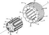
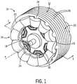
- FIGS. 1 and 2are perspective views of a synchronous reluctance machine that includes a dual magnetic phase material ring therein, according to an embodiment of the invention.
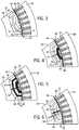
- FIGS. 3-6are partial cross sectional views of a rotor lamination and a dual magnetic phase material ring in the synchronous reluctance machine of FIGS. 1 and 2 , taken along line 1 - 1 of FIG. 1 , according to embodiments of the invention.
- FIG. 7is a graph illustrating a power capability of a synchronous reluctance machine when incorporating the dual magnetic phase material rings of FIGS. 3-6 .
- FIG. 8is a graph illustrating a power factor of a synchronous reluctance machine when incorporating the dual magnetic phase material rings of FIGS. 3-6 .
- FIG. 9is a graph illustrating a power density of a synchronous reluctance machine when incorporating the dual magnetic phase material rings of FIGS. 3-6 .
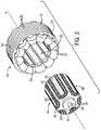
- FIGS. 10 and 11are perspective views of a squirrel cage AC induction machine that includes a dual magnetic phase material ring therein, according to an embodiment of the invention.
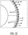
- FIG. 12is a partial cross sectional view of a rotor lamination and the dual magnetic phase material ring in the AC induction machine of FIGS. 10 and 11 , taken along line 10 - 10 of FIG. 10 , according to an embodiment of the invention.
- FIGS. 13 and 14a partial cross sectional view of a rotor lamination and a dual magnetic phase material ring for use in a wound rotor AC induction machine, according to an embodiment of the invention.
- Embodiments of the inventionare directed to dual magnetic phase material rings for use in AC electrical machine, with the dual magnetic phase material being used in combination with rotor laminations of standard construction so as to provide desirable high speed performance of the machine, while also providing for the recovery of low speed power densities. While embodiments of the invention are described here below with respect to the inclusion of dual magnetic phase material rings a into synchronous reluctance machine and an induction machine, it is recognized that these dual magnetic phase material rings may be included in other types of AC electrical machines of various construction, including surface permanent magnet machines, for example. Accordingly, it is to be understood that embodiments of the invention are not to be limited to the specific AC electrical machine types described here below.
- AC electric machine 10is structured as a synchronous reluctance machine that includes a stator assembly 12 (i.e., “stator”) and a rotor assembly 14 (i.e., “rotor”) that are substantially concentrically disposed, with the rotor 14 being positioned within a stator bore 16 defined by the stator 12 .
- the rotor 14can be coupled to a shaft 18 that is configured to rotate about an axis a.
- Stator 12is formed of a stator core 20 and windings 22 that are wound on the stator core 20 .
- the stator core 20is generally defined to include a core main body 23 and a plurality of teeth 24 positioned at a predetermined pitch along a circumferential direction of the main body 22 .
- the stator core 20is composed of a large number of thin plates or laminations 26 that are stacked axially and pressed to form the stator core 20 .
- the laminations 26are formed of a material that can be stamped or cut, for example, to form the metallic laminations. According to an embodiment of the invention, the laminations 26 may be made of made of an electromagnetic steel material. Windings 22 may be wound on the respective teeth 24 , with slots 28 formed between adjacent teeth 24 along the circumferential direction to accommodate the windings 22 .
- the rotor 14 of synchronous reluctance machine 10is formed of a plurality of rotor laminations 30 dispersed axially along the length of rotor 14 and that are stacked axially and pressed to form the rotor.
- the rotor laminations 30are formed of a material that can be stamped or cut, for example, to form the metallic laminations, such as silicon-steel for example.
- Each rotor lamination 30includes therein intermittent air gaps 32 that define a number of rotor poles 34 acting as salient magnetic poles through magnetic reluctance.
- the number of rotor poles 34is equal to the number of stator poles 36 , with the rotor poles 34 being arranged to introduce internal flux “barriers”, holes which direct the magnetic flux along a so-called direct axis.
- stator 12In operation of synchronous reluctance machine 10 , an excitation current is provided to stator 12 such that current flows through stator windings 22 and causes the stator poles 36 to become energized.
- stator pole 36When a stator pole 36 is energized, the rotor torque is in the direction that will reduce reluctance.
- the nearest rotor pole 34is pulled from the unaligned position into alignment with the stator field (a position of less reluctance).
- the stator fieldIn order to sustain rotation, the stator field must rotate in advance of the rotor poles 34 , thus constantly “pulling” the rotor along.
- a sleeve or ring 38is included in of synchronous reluctance machine 10 and is positioned about the stack of rotor laminations 30 , such as by being shrink fit about the stack of rotor laminations 30 .
- the ring 38is in the form a dual magnetic phase material that includes portions that are magnetic and portions that are non-magnetic (i.e., magnetic portions 40 and non-magnetic portions 42 )—with the ring 38 being formed such that the magnetic portions 40 align with the rotor poles 34 of rotor 14 and the non-magnetic portions 42 align with the air gaps 32 between the rotor poles 34 .
- the ring 38is composed of a dual magnetic phase material such as a silicon-steel-chromium material or another suitable material that can be selectively treated to form the magnetic portions 40 and the non-magnetic portions 42 in the ring 38 .
- the dual magnetic phase materialcan initially have magnetic properties, with a heat treating being applied to desired areas of the ring 38 to render those areas non-magnetic and thereby minimize magnetic leakage flux through the non-magnetic areas. It is recognized, however, that other processes/treatments could be employed to render areas of the ring 38 non-magnetic, such as mechanical stress or nitriding treatments.
- dual magnetic phase material ring 38 in synchronous reluctance machine 10beneficially allows for efficient operation of the machine at both low and high speeds, and at low and high saturation conditions. That is, the conventional rotor laminations 30 (i.e., formed of only a single magnetic phase material) provide a desirable level of saturation flux density so as to provide for efficient low speed power densities in the machine 10 (especially under low speed conditions, high saturation conditions), while the inclusion of the dual phase magnetic material ring 38 alongside the conventional rotor laminations 30 provide for efficient operation and performance of the machine at high speed conditions.
- FIGS. 3-6various designs of dual magnetic phase material rings that may be included in synchronous reluctance machine 10 are shown in cross-section (taken along line 1 - 1 of FIG. 1 ), according to embodiments of the invention.
- FIG. 3(Ring_V 1 ) illustrates a true cylindrical profile 44 of the dual magnetic phase material ring 38 that may be included in machine 10 , with such a cylindrical ring being easily shrink fit onto the stack of rotor laminations 30 .
- 4-6illustrate more complex designs of dual magnetic phase material rings that may be included in machine 10 and formed to specifically mate with corresponding designs of rotor laminations 30 , with the specific shape and features of these ring structures being designed to provide desirable power capability and power density/power factor in the machine 10 , as explained in greater detail below.
- the dual magnetic phase material ring 38 of FIG. 4(Ring_V 2 ) is formed with an outer ring/sleeve 44 and a generally U-shaped structure 46 that extends radially inward from the outer ring/sleeve 44 .
- the U-shaped structure 46is formed as a magnetic portion 40 of the magnetic phase material ring 38 , with connecting portions that connect the U-shaped 46 structure to the outer ring/sleeve 44 and to the rotor laminations 30 being formed as non-magnetic portions 42 .
- the dual magnetic phase material ring of FIG. 5(Ring_V 3 ) is formed with a cylindrical outer ring/sleeve 44 and a generally double U-shaped structure that extends radially inward from the outer ring/sleeve 44 .
- the double U-shaped structureis formed of two individual U-shaped structures 46 , 48 that are magnetic portions 40 of the magnetic phase material ring 38 , with connecting portions that connect the double U-shaped structure 46 , 48 to the outer ring/sleeve 44 and to the rotor laminations 30 being formed as non-magnetic portions 42 .
- the dual magnetic phase material ring of FIG. 6has a primarily cylindrical profile, but includes a linear protrusion 50 that extends radially inward from an outer ring/sleeve 44 and through a majority of the rotor lamination 30 .
- alternating portions of the linear protrusion 50are magnetic 40 and non-magnetic 42 , with the magnetic portions 40 being aligned with material of the rotor laminations 30 and the non-magnetic portions 42 being aligned with intermittent air gaps 32 formed in the rotor laminations 30 .
- the specific shape and features of the dual magnetic phase material ringmay be selected to provide desirable power capability and power density/power factor in the machine 10 .
- the power capability, power factor, and power density in the machine 10will vary based on the design of the dual magnetic phase material ring 38 , with these parameters illustrated therein in comparison to a “baseline” value of an electric machine with no dual magnetic phase material ring included therein.
- the power capability ( FIG. 7 ) and power factor ( FIG. 8 )vary dependent on the ring construction, with the dual magnetic phase material ring of FIG. 5 (Ring_V 3 ) showing preferred values/levels of power capability and power factor across a full operating range of the machine.
- the dual magnetic phase material rings of FIGS. 4 and 5show the best levels of power density.
- Induction motor 52includes a stator assembly 12 (i.e., “stator”) and a rotor assembly 54 (i.e., “rotor”).
- Stator 12is formed of a stator core 20 and windings 22 that are wound on the stator core 20 .
- the stator core 20is generally defined to include a core main body 23 and a plurality of teeth 24 positioned at a predetermined pitch along a circumferential direction of the main body 20 .
- the stator core 20is composed of a large number of thin plates or laminations 26 that are stacked axially and pressed to form the stator core.
- the laminations 26are formed of a material that can be stamped or cut, for example, to form the metallic laminations.
- the laminations 26may be made of made of an electromagnetic steel material. Windings 22 may be wound on the respective teeth 24 , with slots (not shown) formed between adjacent teeth 24 along the circumferential direction to accommodate the windings.
- rotor assembly 54is constructed as a squirrel-cage type rotor that includes a rotor core 56 , end rings 58 , and a number of rotor bars 60 coupled to the rotor core 56 and extending between the end rings 58 .
- the rotor core 56is not formed as a single, solid machined piece, but instead is comprised of a plurality of thin plate rotor laminations 62 that are stacked axially and pressed to form the rotor, with such a rotor lamination 62 being shown in FIG. 12 .
- Each of the laminations 62is formed of a material that can be stamped or cut, for example, to form the metallic laminations.
- the rotor bars 60 of the rotor assembly 54are positioned within slots formed in the rotor core 56 (i.e., the slots in each lamination 62 ) and can be formed either as solid copper bars that are inserted into the slots and brazed to two solid copper end-rings at either end of the rotor, or can be casted out of aluminum or copper using the assembled rotor core as the mold for the bar sections of the cage.
- an excitation currentis provided to stator 12 such that current flows through stator windings 22 .
- the flow of current through windings 22creates a rotating magnetic field in an air gap (not shown) between the stator 12 and rotor 54 that induces current flow through rotor bars 60 .
- These currentsinteract with the rotating magnetic field created by the stator 12 and, in effect, cause a rotational motion on the rotor 54 .
- a sleeve or ring 64is included in induction machine 52 and is positioned about the rotor 54 , such as by being shrink fit thereabout.
- the ring 64is in the form a dual magnetic phase material that includes portions that are magnetic and portions that are non-magnetic 66 , 68 —with the ring being formed such that the magnetic portions 66 align with rotor poles 70 of rotor 54 and the non-magnetic portions 68 align with the slots between the rotor poles 70 .
- the ring 64is composed of a dual magnetic phase material such as a silicon-steel—chromium material or another suitable material that can be selectively treated to form the magnetic portions 66 and the non-magnetic portions 68 in the ring.
- the dual magnetic phase materialcan initially have magnetic properties, with a heat treating being applied to desired areas of the ring 64 to render those areas non-magnetic. It is recognized, however, that other processes/treatments could be employed to render areas of the ring 64 non-magnetic, such as mechanical stress or nitriding treatments.
- a dual magnetic phase material ring 64 in induction machine 52beneficially allows for efficient operation of the machine 52 at both low and high speeds, and at low and high saturation conditions. That is, the conventional rotor laminations 62 provide a desirable level of saturation flux density so as to provide for efficient low speed power densities in the machine 52 (especially under low speed conditions, high saturation conditions), while the inclusion of the dual phase magnetic material rings 64 alongside the conventional rotor laminations 62 provide for efficient operation and performance of the machine at high speed conditions.
- FIGS. 10-12While the induction machine 52 of FIGS. 10-12 is shown as including a squirrel-cage rotor, it is recognized that an embodiment of the invention could instead be constructed as an induction machine having a wound field rotor.
- a wound field rotor 72 for use in an induction machineis shown that includes a plurality of conductive wires 74 wound within slots between poles 76 of a rotor core 78 . Similar to the induction machine 52 having a squirrel-cage rotor ( FIGS.
- a dual magnetic phase material ring 64is positioned about the rotor (i.e., about rotor core 78 and rotor windings 74 ) that includes portions that are magnetic 66 and portions that are non-magnetic 68 —with the ring 64 being formed such that the magnetic portions 66 align with rotor poles 76 of rotor 72 and the non-magnetic portions 68 align with the slots between the rotor poles 76 .
- the inclusion of dual magnetic phase material ring 64 in an induction machine, and the combination thereof with conventional rotor laminations 62beneficially allows for efficient operation of the machine at both low and high speeds, and at low and high saturation conditions, with desirable power capability and power densities being provided.
- embodiments of the inventionthus provide an AC electric machine having conventional rotor laminations (such as those formed of silicon-steel for example) with a singular magnetic phase and a ring or sleeve about the rotor that is formed of a dual magnetic phase material.
- the combination of the conventional rotor laminations and a dual magnetic phase material ring in the electric machineallows for efficient operation of the machine at both low and high speeds, and at low and high saturation conditions—with the conventional rotor laminations providing a desirable level of saturation flux density so as to provide for efficient low speed power densities in the machine (especially under low speed conditions, high saturation conditions) and the dual phase magnetic material rings alongside the conventional rotor laminations providing for efficient operation and performance of the machine at high speed conditions.
- the rotor laminationsare conventional laminations, the cost and complexity of manufacturing the rotor is reduced, particularly in comparison to rotors with dual magnetic phase material laminations.
- an AC electric machineincludes a stator assembly and a rotor assembly positioned within the stator assembly and configured to rotate relative thereto, the rotor assembly comprising a rotor core including a stack of rotor laminations that collectively form the rotor core, the rotor core including a plurality of rotor poles separated by gaps therebetween.
- the AC electric machinealso includes a dual magnetic phase material ring positioned about the stack of rotor laminations, the dual magnetic phase material ring comprising a first ring portion comprising a magnetic portion and a second ring portion comprising a non-magnetic portion.
- a rotor assembly for an AC electric machineincludes a rotor core comprising a stack of rotor laminations that collectively form the rotor core, the rotor core including a plurality of rotor poles separated by gaps therebetween.
- the rotor assemblyalso includes a dual magnetic phase material sleeve positioned about the rotor core, the dual magnetic phase material sleeve including a first sleeve portion comprising a magnetic portion and a second sleeve portion comprising a non-magnetic portion, wherein the first sleeve portion is adjacent to the rotor poles of the rotor core and the second sleeve portion is adjacent to the gaps between the rotor poles of the rotor core.
- a method for manufacturing an AC electric machineincludes providing a stator defining a stator bore and providing a rotor assembly for positioning within the stator bore that is configured to rotate relative thereto.
- Providing the rotor assemblyfurther comprises arranging and assembling a plurality of rotor laminations to form a rotor core having a plurality of rotor poles separated by gaps therebetween and positioning a dual magnetic phase material ring about the rotor core that is formed of a magnetic phase material that is magnetic in a first state and non-magnetic in a second state, wherein portions of the dual magnetic phase material ring adjacent the plurality of rotor poles are in the first state and wherein portions of the dual magnetic phase material ring adjacent the gaps between the plurality of rotor poles are in the second state.
Landscapes
- Engineering & Computer Science (AREA)
- Power Engineering (AREA)
- Iron Core Of Rotating Electric Machines (AREA)
Abstract
Description
Claims (20)
Priority Applications (4)
| Application Number | Priority Date | Filing Date | Title |
|---|---|---|---|
| US15/598,408US10749385B2 (en) | 2017-05-18 | 2017-05-18 | Dual magnetic phase material rings for AC electric machines |
| EP18803259.3AEP3625874A4 (en) | 2017-05-18 | 2018-03-16 | Dual magnetic phase material rings for ac electric machines |
| PCT/US2018/022999WO2018212828A1 (en) | 2017-05-18 | 2018-03-16 | Dual magnetic phase material rings for ac electric machines |
| CN201880031728.7ACN110663158B (en) | 2017-05-18 | 2018-03-16 | Dual magnetic phase material ring for AC motor |
Applications Claiming Priority (1)
| Application Number | Priority Date | Filing Date | Title |
|---|---|---|---|
| US15/598,408US10749385B2 (en) | 2017-05-18 | 2017-05-18 | Dual magnetic phase material rings for AC electric machines |
Publications (2)
| Publication Number | Publication Date |
|---|---|
| US20180337565A1 US20180337565A1 (en) | 2018-11-22 |
| US10749385B2true US10749385B2 (en) | 2020-08-18 |
Family
ID=64272781
Family Applications (1)
| Application Number | Title | Priority Date | Filing Date |
|---|---|---|---|
| US15/598,408Active2038-05-28US10749385B2 (en) | 2017-05-18 | 2017-05-18 | Dual magnetic phase material rings for AC electric machines |
Country Status (4)
| Country | Link |
|---|---|
| US (1) | US10749385B2 (en) |
| EP (1) | EP3625874A4 (en) |
| CN (1) | CN110663158B (en) |
| WO (1) | WO2018212828A1 (en) |
Cited By (3)
| Publication number | Priority date | Publication date | Assignee | Title |
|---|---|---|---|---|
| KR20210048501A (en)* | 2018-08-07 | 2021-05-03 | 타우 모터스, 인크. | Electric motor |
| US11661646B2 (en) | 2021-04-21 | 2023-05-30 | General Electric Comapny | Dual phase magnetic material component and method of its formation |
| US11926880B2 (en) | 2021-04-21 | 2024-03-12 | General Electric Company | Fabrication method for a component having magnetic and non-magnetic dual phases |
Families Citing this family (6)
| Publication number | Priority date | Publication date | Assignee | Title |
|---|---|---|---|---|
| US10673288B2 (en) | 2013-10-31 | 2020-06-02 | General Electric Company | Method for forming a nitrogenation barrier and machine formed using a body having the nitrogenation barrier |
| US11362552B2 (en)* | 2018-10-09 | 2022-06-14 | Ford Global Technologies, Llc | Electric machine component and method to fabricate |
| DE102019218437A1 (en)* | 2019-11-28 | 2021-06-02 | Robert Bosch Gmbh | Rotor for an electric machine and method for manufacturing a rotor |
| US12155266B2 (en)* | 2021-11-30 | 2024-11-26 | GM Global Technology Operations LLC | Bridgeless and webless rotor assembly using polymer composites |
| DE102022106874A1 (en)* | 2022-03-23 | 2023-09-28 | Borgwarner Inc. | Reluctance machine |
| US20250158464A1 (en)* | 2023-11-15 | 2025-05-15 | GM Global Technology Operations LLC | Selective permeability rotor sleeve for interior permanent magnet machine |
Citations (19)
| Publication number | Priority date | Publication date | Assignee | Title |
|---|---|---|---|---|
| US4724348A (en)* | 1984-12-03 | 1988-02-09 | General Electric Company | Rotatable assembly for dynamoelectric machines having means for reducing release of magnet material particles therefrom |
| US6274960B1 (en)* | 1998-09-29 | 2001-08-14 | Kabushiki Kaisha Toshiba | Reluctance type rotating machine with permanent magnets |
| US6534891B2 (en) | 1992-01-15 | 2003-03-18 | General Electric Company | High speed induction motor rotor and method of fabrication |
| US20090021105A1 (en)* | 2006-07-12 | 2009-01-22 | Steven Andrew Evans | Rotor for an electric machine and production method thereof |
| US7652404B2 (en) | 2007-05-31 | 2010-01-26 | General Electric Company | Synchronous reluctance machine |
| US8018110B2 (en) | 2009-04-30 | 2011-09-13 | General Electric Company | High speed internal permanent magnet machine and method of manufacturing the same |
| WO2011151138A2 (en) | 2010-05-31 | 2011-12-08 | Robert Bosch Gmbh | Electrical machine with reduced noise development |
| JP2012518378A (en) | 2009-02-13 | 2012-08-09 | アイシス イノベイシヨン リミテツド | Electric machine-magnetic flux |
| KR20130049189A (en) | 2013-04-23 | 2013-05-13 | 류호민 | Development magnetic induced |
| US20130214620A1 (en)* | 2012-02-16 | 2013-08-22 | Fanuc Corporation | Rotor of electric motor having structure for attaching magnet securely to outer circumferential surface of rotor core and manufacturing method thereof |
| JP2014050218A (en) | 2012-08-31 | 2014-03-17 | Denso Corp | Multi-gap type rotary electric machine |
| US8729766B2 (en) | 2008-08-27 | 2014-05-20 | Robert Bosch Gmbh | Electric machine |
| US8836196B2 (en) | 2010-11-17 | 2014-09-16 | Electric Torque Machines, Inc. | Transverse and/or commutated flux systems having segmented stator laminations |
| US20140265708A1 (en) | 2013-03-14 | 2014-09-18 | General Electric Company | Dual magnetic phase rotor laminations for induction machines |
| US20150115757A1 (en)* | 2013-10-25 | 2015-04-30 | General Electric Company | System and method for heating ferrite magnet motors for low temperatures |
| US20150171682A1 (en)* | 2012-05-28 | 2015-06-18 | Aida Engineering, Ltd. | Composite torque rotating electric machine |
| US20150295454A1 (en) | 2014-04-15 | 2015-10-15 | General Electric Company | Induction machine with dual phase magnetic material for sensorless control |
| US20160087503A1 (en) | 2013-02-28 | 2016-03-24 | General Electric Company | Electric machine stator lamination with dual phase magnetic material |
| US20160294236A1 (en) | 2015-04-01 | 2016-10-06 | General Electric Company | System and method for supporting laminations of synchronous reluctance motors |
Family Cites Families (7)
| Publication number | Priority date | Publication date | Assignee | Title |
|---|---|---|---|---|
| JPH10257700A (en)* | 1997-03-13 | 1998-09-25 | Matsushita Electric Ind Co Ltd | Rotor core |
| US20030193258A1 (en) | 2002-04-16 | 2003-10-16 | Reiter Frederick B. | Composite powder metal rotor sleeve |
| US7489062B2 (en)* | 2005-11-14 | 2009-02-10 | General Electric Company | Synchronous reluctance machine with a novel rotor topology |
| US20080238236A1 (en)* | 2007-03-27 | 2008-10-02 | General Electric Company | Switched reluctance machine |
| JP5423770B2 (en)* | 2011-11-15 | 2014-02-19 | 株式会社デンソー | Multi-gap rotating electric machine |
| EP3070824A1 (en)* | 2015-03-19 | 2016-09-21 | Siemens Aktiengesellschaft | Rotor of a synchronous reluctance machine |
| JP6600994B2 (en)* | 2015-06-02 | 2019-11-06 | 株式会社ジェイテクト | Method for manufacturing embedded magnet type rotor unit and magnetizing apparatus |
- 2017
- 2017-05-18USUS15/598,408patent/US10749385B2/enactiveActive
- 2018
- 2018-03-16WOPCT/US2018/022999patent/WO2018212828A1/ennot_activeCeased
- 2018-03-16EPEP18803259.3Apatent/EP3625874A4/enactivePending
- 2018-03-16CNCN201880031728.7Apatent/CN110663158B/enactiveActive
Patent Citations (19)
| Publication number | Priority date | Publication date | Assignee | Title |
|---|---|---|---|---|
| US4724348A (en)* | 1984-12-03 | 1988-02-09 | General Electric Company | Rotatable assembly for dynamoelectric machines having means for reducing release of magnet material particles therefrom |
| US6534891B2 (en) | 1992-01-15 | 2003-03-18 | General Electric Company | High speed induction motor rotor and method of fabrication |
| US6274960B1 (en)* | 1998-09-29 | 2001-08-14 | Kabushiki Kaisha Toshiba | Reluctance type rotating machine with permanent magnets |
| US20090021105A1 (en)* | 2006-07-12 | 2009-01-22 | Steven Andrew Evans | Rotor for an electric machine and production method thereof |
| US7652404B2 (en) | 2007-05-31 | 2010-01-26 | General Electric Company | Synchronous reluctance machine |
| US8729766B2 (en) | 2008-08-27 | 2014-05-20 | Robert Bosch Gmbh | Electric machine |
| JP2012518378A (en) | 2009-02-13 | 2012-08-09 | アイシス イノベイシヨン リミテツド | Electric machine-magnetic flux |
| US8018110B2 (en) | 2009-04-30 | 2011-09-13 | General Electric Company | High speed internal permanent magnet machine and method of manufacturing the same |
| WO2011151138A2 (en) | 2010-05-31 | 2011-12-08 | Robert Bosch Gmbh | Electrical machine with reduced noise development |
| US8836196B2 (en) | 2010-11-17 | 2014-09-16 | Electric Torque Machines, Inc. | Transverse and/or commutated flux systems having segmented stator laminations |
| US20130214620A1 (en)* | 2012-02-16 | 2013-08-22 | Fanuc Corporation | Rotor of electric motor having structure for attaching magnet securely to outer circumferential surface of rotor core and manufacturing method thereof |
| US20150171682A1 (en)* | 2012-05-28 | 2015-06-18 | Aida Engineering, Ltd. | Composite torque rotating electric machine |
| JP2014050218A (en) | 2012-08-31 | 2014-03-17 | Denso Corp | Multi-gap type rotary electric machine |
| US20160087503A1 (en) | 2013-02-28 | 2016-03-24 | General Electric Company | Electric machine stator lamination with dual phase magnetic material |
| US20140265708A1 (en) | 2013-03-14 | 2014-09-18 | General Electric Company | Dual magnetic phase rotor laminations for induction machines |
| KR20130049189A (en) | 2013-04-23 | 2013-05-13 | 류호민 | Development magnetic induced |
| US20150115757A1 (en)* | 2013-10-25 | 2015-04-30 | General Electric Company | System and method for heating ferrite magnet motors for low temperatures |
| US20150295454A1 (en) | 2014-04-15 | 2015-10-15 | General Electric Company | Induction machine with dual phase magnetic material for sensorless control |
| US20160294236A1 (en) | 2015-04-01 | 2016-10-06 | General Electric Company | System and method for supporting laminations of synchronous reluctance motors |
Non-Patent Citations (2)
| Title |
|---|
| International Search Report and Written Opinion issued in connection with corresponding PCT Application No. PCT/US2018/022999 dated Jul. 2, 2018. |
| Wang et al., "Fabrication and Experimental Analysis of an Axially Laminated Flux-Switching Permanent-Magnet Machine", IEEE Transactions on Industrial Electronics, Feb. 2017, vol. 64, No. 2, pp. 1081-1091. |
Cited By (6)
| Publication number | Priority date | Publication date | Assignee | Title |
|---|---|---|---|---|
| KR20210048501A (en)* | 2018-08-07 | 2021-05-03 | 타우 모터스, 인크. | Electric motor |
| KR102758251B1 (en) | 2018-08-07 | 2025-01-21 | 타우 모터스, 인크. | electric motor |
| US12249874B2 (en) | 2018-08-07 | 2025-03-11 | Tau Motors, Inc. | Electric motors |
| US11661646B2 (en) | 2021-04-21 | 2023-05-30 | General Electric Comapny | Dual phase magnetic material component and method of its formation |
| US11926880B2 (en) | 2021-04-21 | 2024-03-12 | General Electric Company | Fabrication method for a component having magnetic and non-magnetic dual phases |
| US11976367B2 (en) | 2021-04-21 | 2024-05-07 | General Electric Company | Dual phase magnetic material component and method of its formation |
Also Published As
| Publication number | Publication date |
|---|---|
| WO2018212828A1 (en) | 2018-11-22 |
| CN110663158A (en) | 2020-01-07 |
| EP3625874A1 (en) | 2020-03-25 |
| US20180337565A1 (en) | 2018-11-22 |
| CN110663158B (en) | 2022-08-02 |
| EP3625874A4 (en) | 2021-01-27 |
Similar Documents
| Publication | Publication Date | Title |
|---|---|---|
| US10749385B2 (en) | Dual magnetic phase material rings for AC electric machines | |
| US6274960B1 (en) | Reluctance type rotating machine with permanent magnets | |
| US8154167B2 (en) | Induction motor lamination design | |
| EP2980969B1 (en) | Synchronous reluctance motor and rotor for synchronous reluctance motor | |
| CN103872868B (en) | Multiple level formula electric rotating machine | |
| CN111614181B (en) | Rotor structure and motor of permanent magnet assisted reluctance motor with self-starting hybrid excitation | |
| US8169109B2 (en) | Electrical machine with dual radial airgaps | |
| US8294321B2 (en) | Brushless machine having ferromagnetic side plates and side magnets | |
| US12095394B2 (en) | Induction machines without permanent magnets | |
| EP2456048B1 (en) | Rotor structure for a fault-tolerant permanent magnet electromotive machine and corresponding method | |
| JP2018082605A (en) | Sleeve rotor synchronous reluctance electric machine | |
| US20140306565A1 (en) | Coaxial Motor | |
| JP6048191B2 (en) | Multi-gap rotating electric machine | |
| JP2000197325A (en) | Reluctance motor | |
| US20220368183A1 (en) | Rotor for a synchronous machine | |
| CN209805521U (en) | Rotor structure of direct-start synchronous reluctance motor and motor | |
| RU2246167C1 (en) | Face-type electrical machine | |
| US20240055916A1 (en) | Wound-field synchronous machines and control | |
| WO2011089797A1 (en) | Rotor, rotating electrical machine using same, and power generator | |
| US12057749B2 (en) | Stator assembly flux alignment | |
| JP2007288838A (en) | Embedded magnet type motor | |
| JPH11252835A (en) | Rotor of permanent magnet dynamoelectric machine and high-revolution type permanent magnet dynamoelectric machine | |
| WO2024084542A1 (en) | Rotary electric machine | |
| JP2009106045A (en) | Rotating electric machine | |
| JP2003134761A (en) | Induction start type synchronous reluctance motor |
Legal Events
| Date | Code | Title | Description |
|---|---|---|---|
| AS | Assignment | Owner name:GENERAL ELECTRIC COMPANY, NEW YORK Free format text:ASSIGNMENT OF ASSIGNORS INTEREST;ASSIGNORS:REDDY, PATEL BHAGEERATH;ZOU, MIN;EL-REFAIE, AYMAN MOHAMED FAWZI;AND OTHERS;SIGNING DATES FROM 20170406 TO 20170522;REEL/FRAME:042977/0918 | |
| STPP | Information on status: patent application and granting procedure in general | Free format text:DOCKETED NEW CASE - READY FOR EXAMINATION | |
| AS | Assignment | Owner name:UNITED STATES DEPARTMENT OF ENERGY, DISTRICT OF COLUMBIA Free format text:CONFIRMATORY LICENSE;ASSIGNOR:GENERAL ELECTRIC GLOBAL RESEARCH CTR;REEL/FRAME:047995/0508 Effective date:20170525 Owner name:UNITED STATES DEPARTMENT OF ENERGY, DISTRICT OF CO Free format text:CONFIRMATORY LICENSE;ASSIGNOR:GENERAL ELECTRIC GLOBAL RESEARCH CTR;REEL/FRAME:047995/0508 Effective date:20170525 | |
| STPP | Information on status: patent application and granting procedure in general | Free format text:NON FINAL ACTION MAILED | |
| STPP | Information on status: patent application and granting procedure in general | Free format text:RESPONSE TO NON-FINAL OFFICE ACTION ENTERED AND FORWARDED TO EXAMINER | |
| STPP | Information on status: patent application and granting procedure in general | Free format text:NOTICE OF ALLOWANCE MAILED -- APPLICATION RECEIVED IN OFFICE OF PUBLICATIONS | |
| STPP | Information on status: patent application and granting procedure in general | Free format text:PUBLICATIONS -- ISSUE FEE PAYMENT VERIFIED | |
| STPP | Information on status: patent application and granting procedure in general | Free format text:PUBLICATIONS -- ISSUE FEE PAYMENT VERIFIED | |
| STCF | Information on status: patent grant | Free format text:PATENTED CASE | |
| MAFP | Maintenance fee payment | Free format text:PAYMENT OF MAINTENANCE FEE, 4TH YEAR, LARGE ENTITY (ORIGINAL EVENT CODE: M1551); ENTITY STATUS OF PATENT OWNER: LARGE ENTITY Year of fee payment:4 | |
| AS | Assignment | Owner name:EDISON INNOVATIONS, LLC, TEXAS Free format text:ASSIGNMENT OF ASSIGNORS INTEREST;ASSIGNOR:DOLBY INTELLECTUAL PROPERTY LICENSING, LLC;REEL/FRAME:070293/0273 Effective date:20250219 | |
| AS | Assignment | Owner name:GE INTELLECTUAL PROPERTY LICENSING, LLC, NEW YORK Free format text:ASSIGNMENT OF ASSIGNORS INTEREST;ASSIGNOR:GENERAL ELECTRIC COMPANY;REEL/FRAME:070636/0815 Effective date:20240630 Owner name:DOLBY INTELLECTUAL PROPERTY LICENSING, LLC, NEW YORK Free format text:CHANGE OF NAME;ASSIGNOR:GE INTELLECTUAL PROPERTY LICENSING, LLC;REEL/FRAME:070643/0907 Effective date:20240819 |