US10749249B2 - Display panel with integrated small cell and billboard with integrated macro site - Google Patents
Display panel with integrated small cell and billboard with integrated macro siteDownload PDFInfo
- Publication number
- US10749249B2 US10749249B2US15/469,695US201715469695AUS10749249B2US 10749249 B2US10749249 B2US 10749249B2US 201715469695 AUS201715469695 AUS 201715469695AUS 10749249 B2US10749249 B2US 10749249B2
- Authority
- US
- United States
- Prior art keywords
- base station
- small cell
- antenna
- cell base
- radio
- Prior art date
- Legal status (The legal status is an assumption and is not a legal conclusion. Google has not performed a legal analysis and makes no representation as to the accuracy of the status listed.)
- Active
Links
Images


Classifications
- H—ELECTRICITY
- H01—ELECTRIC ELEMENTS
- H01Q—ANTENNAS, i.e. RADIO AERIALS
- H01Q1/00—Details of, or arrangements associated with, antennas
- H01Q1/12—Supports; Mounting means
- H01Q1/22—Supports; Mounting means by structural association with other equipment or articles
- H01Q1/24—Supports; Mounting means by structural association with other equipment or articles with receiving set
- H01Q1/241—Supports; Mounting means by structural association with other equipment or articles with receiving set used in mobile communications, e.g. GSM
- H01Q1/246—Supports; Mounting means by structural association with other equipment or articles with receiving set used in mobile communications, e.g. GSM specially adapted for base stations
- H—ELECTRICITY
- H01—ELECTRIC ELEMENTS
- H01Q—ANTENNAS, i.e. RADIO AERIALS
- H01Q1/00—Details of, or arrangements associated with, antennas
- H01Q1/12—Supports; Mounting means
- H01Q1/1207—Supports; Mounting means for fastening a rigid aerial element
- H01Q1/1228—Supports; Mounting means for fastening a rigid aerial element on a boom
- H—ELECTRICITY
- H01—ELECTRIC ELEMENTS
- H01Q—ANTENNAS, i.e. RADIO AERIALS
- H01Q1/00—Details of, or arrangements associated with, antennas
- H01Q1/12—Supports; Mounting means
- H01Q1/1242—Rigid masts specially adapted for supporting an aerial
- H—ELECTRICITY
- H01—ELECTRIC ELEMENTS
- H01Q—ANTENNAS, i.e. RADIO AERIALS
- H01Q1/00—Details of, or arrangements associated with, antennas
- H01Q1/42—Housings not intimately mechanically associated with radiating elements, e.g. radome
- H—ELECTRICITY
- H01—ELECTRIC ELEMENTS
- H01Q—ANTENNAS, i.e. RADIO AERIALS
- H01Q1/00—Details of, or arrangements associated with, antennas
- H01Q1/42—Housings not intimately mechanically associated with radiating elements, e.g. radome
- H01Q1/427—Flexible radomes
- H—ELECTRICITY
- H01—ELECTRIC ELEMENTS
- H01Q—ANTENNAS, i.e. RADIO AERIALS
- H01Q21/00—Antenna arrays or systems
- H01Q21/06—Arrays of individually energised antenna units similarly polarised and spaced apart
- H01Q21/20—Arrays of individually energised antenna units similarly polarised and spaced apart the units being spaced along or adjacent to a curvilinear path
- H01Q21/205—Arrays of individually energised antenna units similarly polarised and spaced apart the units being spaced along or adjacent to a curvilinear path providing an omnidirectional coverage
- H—ELECTRICITY
- H01—ELECTRIC ELEMENTS
- H01Q—ANTENNAS, i.e. RADIO AERIALS
- H01Q21/00—Antenna arrays or systems
- H01Q21/28—Combinations of substantially independent non-interacting antenna units or systems
- H—ELECTRICITY
- H01—ELECTRIC ELEMENTS
- H01Q—ANTENNAS, i.e. RADIO AERIALS
- H01Q3/00—Arrangements for changing or varying the orientation or the shape of the directional pattern of the waves radiated from an antenna or antenna system
- H01Q3/02—Arrangements for changing or varying the orientation or the shape of the directional pattern of the waves radiated from an antenna or antenna system using mechanical movement of antenna or antenna system as a whole
- H01Q3/04—Arrangements for changing or varying the orientation or the shape of the directional pattern of the waves radiated from an antenna or antenna system using mechanical movement of antenna or antenna system as a whole for varying one co-ordinate of the orientation
- H—ELECTRICITY
- H04—ELECTRIC COMMUNICATION TECHNIQUE
- H04B—TRANSMISSION
- H04B7/00—Radio transmission systems, i.e. using radiation field
- H04B7/02—Diversity systems; Multi-antenna system, i.e. transmission or reception using multiple antennas
- H04B7/04—Diversity systems; Multi-antenna system, i.e. transmission or reception using multiple antennas using two or more spaced independent antennas
- H—ELECTRICITY
- H04—ELECTRIC COMMUNICATION TECHNIQUE
- H04W—WIRELESS COMMUNICATION NETWORKS
- H04W16/00—Network planning, e.g. coverage or traffic planning tools; Network deployment, e.g. resource partitioning or cells structures
- H04W16/24—Cell structures
- H04W16/28—Cell structures using beam steering
- H—ELECTRICITY
- H04—ELECTRIC COMMUNICATION TECHNIQUE
- H04W—WIRELESS COMMUNICATION NETWORKS
- H04W88/00—Devices specially adapted for wireless communication networks, e.g. terminals, base stations or access point devices
- H04W88/08—Access point devices
Definitions
- aspects of the present disclosurerelate to cellular communications systems, including distributed antenna systems, communications systems that include small cell radio base stations, and communication systems that include macro cell radio base stations.
- Cellular communications systemsare well known in the art.
- a geographic areamay be divided into a series of regions that are referred to as “cells,” and each cell is served by a base station.
- a cellmay serve users who are within a distance of, for example, 2-20 kilometers from the base station, although smaller cells are typically used in urban areas to increase capacity.
- the base stationmay include baseband equipment, radios and antennas that are configured to provide two-way radio frequency (“RF”) communications with mobile subscribers that are positioned throughout the cell.
- RFradio frequency
- the cellmay be divided into a plurality of “sectors,” and separate antennas may provide coverage to each of the sectors.
- a base station antennaincludes one or more phase-controlled arrays of radiating elements, with the radiating elements arranged in one or more vertical columns when the antenna is mounted for use.
- verticalrefers to a direction that is perpendicular relative to the plane defined by the horizon.
- a small cell base stationrefers to a low-power base station that may operate in the licensed and/or unlicensed spectrum that has a much smaller range than a typical “macrocell” base station.
- a small cell base stationmay be designed to serve users who are within short distances from the small cell base station (e.g., tens or hundreds of meters). Small cells may be used, for example, to provide cellular coverage to high traffic areas within a macrocell, which allows the macrocell base station to offload much or all of the traffic in the vicinity of the small cell to the small cell base station.
- Small cellsmay be particularly effective in Long Term Evolution (“LTE”) cellular networks in efficiently using the available frequency spectrum to maximize network capacity at a reasonable cost.
- Small cell base stationstypically employ an antenna that provides full 360 degree coverage in the azimuth plane and a suitable beamwidth in the elevation plane to cover the designed area of the small cell.
- the small cell antennawill be designed to have a small downtilt in the elevation plane to reduce spill-over of the antenna beam of the small cell antenna into regions that are outside the small cell and also for reducing interference between the small cell and the overlaid macro cell.
- DASdistributed antenna systems
- placing antennas on the walls or floors of the spacemay result in unattractive or unappealing equipment placed within a line of sight of individuals traversing the building.
- the equipmentmay attract unwanted attention, such as persons intentionally or unintentionally tampering with the equipment for various reasons.
- digital displaysare being used in the environments discussed above with increasing frequency.
- Some of these digital displayswhich may be referred to herein as display panels, are frequently designed to be slightly taller than an average adult human, although the overall size of the display panel may range from several inches in height and width to several meters.
- the display panelmay be dimensioned to provide a desirable advertising effect in which a person may be exposed easily to an advertising subject. For example, as a person walks toward a departure gate, baggage claim, a store, restaurant, rest room, or other destination, products or services advertised on a screen of the digital display may, because of a placement height of the display panel, be placed in a direct line of sight of a person as the person.
- these displaysmay include an interactive component, inviting a person to touch one or more portions of the display screen to be entertained temporarily (thus creating a positive association with a product or service) or more frequently to receive additional information about the product or service being advertised.
- digital billboardsmay be mounted on a pole or a vertical columnar structure.
- digital billboardsmay provide a suitable environment for placement of radio equipment, either for a small cell or, in some situations, for a macrocell. This desirability may be because power lines and/or data communication lines may already exist at the installation site to service the digital billboards.
- aspects of the present disclosureprovide an apparatus, which includes a digital display device comprising a housing and a digital display.
- the apparatusalso includes a small cell base station, which may include at least one antenna and a radio.
- the small cell base stationmay be mountable on a top surface of the housing.
- the at least one antenna and the radiomay be surrounded by a fabric radome that may conceal the at least one antenna and radio from view when the small cell base station is mounted to the top surface of the housing.
- an apparatusmay include a digital display device that has a mounting structure and a digital display mounted on the mounting structure.
- the apparatusmay include a base station, which may include at least one antenna, at least one radio, and at least one baseband unit each mounted on the mounting structure.
- the at least one radio and the at least one baseband unitmay be concealed from view by the digital display.
- an apparatusmay include a digital display device, which may include a digital display, and a base station, which may include a radio and at least one antenna mounted on a surface of the digital display device. At least one component of the base station may be concealed from view by a concealment device. In some aspects, this concealment device may be a radome. In some aspects, this concealment device may be the digital display.
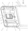
- FIGS. 1 and 2illustrate a front perspective view and a rear perspective view, respectively, of a small cell base station according to one or more aspects.
- FIG. 3illustrates relative dimensions of a small cell base station, a display panel device, and an average sized adult human according to aspects of the present disclosure.
- FIG. 4illustrates a plan view of a first small cell base station according to aspects of the present disclosure.
- FIG. 5illustrates a plan view of a second small cell base station according to aspects of the present disclosure.
- FIG. 6illustrates relative dimensions of a base station, a digital billboard device, and an average sized adult human according to aspects of the present disclosure.
- FIG. 7illustrates components of a base station at least partially concealed by digital billboard devices according to aspects of the present disclosure.
- FIG. 1illustrates a front perspective view of the small cell base station and FIG. 2 illustrates a rear perspective view.
- FIGS. 1 and 2illustrate that the small cell base station 10 may be located atop a display panel device 80 .
- FIG. 3illustrates a rendered view of an exemplary sense of scale of the dimensions of the small cell base station 10 relative to the dimensions of the display panel device 80 and the dimensions of an average sized adult human 90 . It is emphasized that such dimensions are exemplary, and the display panel device 80 and/or small cell base station 10 may have different dimensions than those illustrated in FIG. 3 .
- the small cell base station 10may include one or more antennas 20 - 1 , 20 - 2 , and 20 - 3 that may be mounted on corresponding mounting structures 30 - 1 , 30 - 2 , and 30 - 3 within a radome 40 .
- antennas 20may have an omni-directional antenna pattern in the azimuth plane, meaning that the antenna beam generated by the one or more antennas 20 may extend through a full 360 degree circle in the azimuth plane.
- each given antenna 20 - nmay generate an antenna beam which extends only through an arc portion of a full 360 degree circle.
- each antennamay have an antenna pattern of one-third of a full 360 degree circle in the azimuth plane, or a beam width of 120 degrees.
- Each antennamay have a suitable beamwidth (e.g., 10-30 degrees) in the elevation plane.
- the antenna beammay be slightly down-tilted in the elevation plane to reduce interference with adjacent base stations.
- small cell base station 10may be a remote unit in a distributed antenna system (DAS) and the antennas 20 - n components thereof.
- DASdistributed antenna system
- Mounting structures 30 - 1 , 30 - 2 , and 30 - 3may be pole or other columnar mounts on which the antennas may be mounted. Each mounting structure may be configured to provide for azimuth adjustment of the corresponding antenna 20 - 1 , 20 - 2 , and 20 - 3 . For example, each mounting structure may be configured to rotate (via motors not illustrated in FIGS. 1 and 2 ) about its longitudinal axis, thereby rotating the corresponding antenna 30 - 1 , 30 - 2 , or 30 - 3 in the azimuth plane.
- structures 30 - nmay be columnar antenna mounts, a wide variety of other mounting techniques may be used to mount the corresponding antenna 20 - n within a radome 40 .
- each antenna 20 - nis illustrated as substantially parallel to its corresponding mount 30 - n , in some aspects mechanical downtilt devices (e.g., brackets, adjustments arms, or the like) may be present to provide a mechanical downtilt adjustment of the antenna.
- Such mechanical downtiltmay be in addition to or in the alternative to any electrical downtilt provided by the antennas, a radio 50 (discussed in detail below) and/or other components of small cell base station 10 (e.g., power splitters/combiners and/or phase shifters not illustrated in FIGS. 1 and 2 .
- the small cell base station 10may include base station equipment such as baseband units (not shown) and/or radios 50 . These may also be positioned within the radome 40 , though in some aspects they may be positioned elsewhere and optical fiber or other connections may be used instead.
- radio 50may be located within radome 40 , but in other aspects, radio 50 may be located elsewhere, including within a housing 82 of the display panel device 80 .
- a single radio 50is shown in FIG. 1 to simplify the drawing, but more than one radio 50 may be provided.
- the radio 50may be a remote radio head that is mounted within the radome 40 adjacent the antennas 20 , and in such aspects the baseband units or equipment may be located outside the radome 40 .
- a baseband unitmay receive data from another source such as, for example, a backhaul network (not shown) and may process this data and provide a data stream to the radio 52 .
- the radio 52may generate RF signals that include the data encoded therein and may amplify and deliver these RF signals to the antenna 20 - 1 , 20 - 2 , and 20 - 3 for transmission via respective cabling connections (not shown).
- a microwave backhaul radio and antennamay be included within the small cell base station 10 .
- the radome 40may be able to pass microwave signals to and from the microwave backhaul antenna and radio.
- circuitryconfigured to convert signals between the microwave transmission path and the cellular transmission paths may be provided, although not shown in FIGS. 1 and 2 .
- the radome 40may be manufactured from a fabric material, including a fabric material especially selected for favorable radio frequency transmission properties.
- the radome 40may be screen printed with a neutral color and/or with complementary advertising.
- the radome 40may be removable and replaceable without detaching the small cell base station 10 from the display panel, for example to replace one screen printed radome 40 with a second screen printed radome 40 during an advertising refresh.
- distribution center 60may include fiber and power distribution.
- optical fiber and/or power linkagesmay be provided to the small cell base station 10 including via display panel device 80 (discussed further below).
- the optical fiber and/or power linkagesmay be integrated within the display panel device 80 (e.g., at the time of manufacture) or may be passed through an interior portion or channel of the display panel device 80 at the time of installation of the small cell base station 10 atop the display panel device 80 .
- the distribution center 60may include an alternating current (AC) power and load center.
- ACalternating current
- distribution center 60may provide direct current (DC) rectification.
- distribution center 60may include a battery backup for powering the small cell base station 10 .
- a Global Positioning System (GPS) and/or Indoor Positioning System (IPS) antenna module 70may be provided within the radome 40 or outside of the radome 40 as required.
- the GPS/IPS antenna module 70may be optional.
- the GPS/IPS antenna module 70may provide or relay signals to assist a user equipment in determining its position and/or to assist network equipment in determining the position of a user device.
- a display panel device 80which may include a display panel 81 within a housing 82 .
- the display panel 82may be a display panel, such as an organic light-emitting diode (OLED), a liquid crystal display (LCD) panel, an electrophoretic display panel, an electrowetting display panel, a plasma display panel (PDP) and so on.
- OLEDorganic light-emitting diode
- LCDliquid crystal display
- PDPplasma display panel
- Housing 82may include the display panel 81 and display circuitry (not shown) configured to drive the display panel 81 , though this circuitry may be located outside the housing at a location relatively local to the display panel 81 or remote from the display panel 81 .
- the display circuitrymay include a processor and memory. In some aspects, the display circuitry may be configured to drive signals to the display panel via a driving circuit. In some aspects, the display circuitry may receive data representative of an image (which may be a still image or a video image) from an external device and/or memory (including via a wired or wireless network) and convert or otherwise use the data to display the image on the display panel.
- housing 82may include multiple display panels 81 , each of which may be configured to display the same image or different images. These display panels may be arranged at various locations within the housing 82 and visible through holes or cutouts in the housing 82 .
- a first display panel 81may be located at a first surface of housing 82 , and a second display panel 81 may be located at a second surface of housing 82 opposite from the first display panel 81 .
- a first display panel 81may be located at a first surface of housing 82
- a second display panel 81may be located at a second surface of housing 82 perpendicular from the first display panel 81 .
- a first display panel 81may be located at a first surface of housing 82
- a second display panel 81may be located at the same first surface of housing 82 as the first display panel 81 .
- a display panel 81may be, in some aspects, at least four feet in height and at least two feet in width, although in other aspects, the display panel 81 may be at least six feet in height and at least four feet in width. Such dimensions are merely exemplary.
- display panel 81may be an interactive display panel configured to receive touch or other input from a passerby via interacting circuitry and launch or otherwise enable an interactive session with the passerby. Such functionality may enable the passerby to learn more about a product or service being advertised on the display panel 81 .
- the dimensions of the small cell base station 10may be selected to be compatible with existing display panels that are installed in various locations.
- at least a portion of the small cell base station 10may be concealed from view by one or more concealment devices, which in this case may be either the display panel device 80 and/or radome 40 .
- some components of the small cell base station 10may be concealed within display panel device 80 and components of the small cell base station 10 may be concealed by radome 40 .
- antennas 20 - 1 , 20 - 2 , and 20 - 3 , and their corresponding mounting structures 30 - 1 , 30 - 2 , and 30 - 3may be concealed within the radome 40
- radio 50may be concealed by display panel device 80 .
- “concealed” or “concealed from view”may include the shielding of an a device or component, including its electrical components and any housing surrounding such electrical components, from view by an observer.
- the small cell base station 10 of FIG. 1may include various other equipment such as, for example, a power supply, back-up batteries, a power bus, Antenna Interface Signal Group (“AISG”) controllers and the like that are not illustrated in FIG. 1 . In some aspects, these may be located within the housing 82 of the display panel device 80 , although in some aspects, the small cell base station 10 may be installed as a retro-fit module and/or as an add-on module atop an already installed display panel device 80 . In such aspects, the small cell base station 10 may be configured to receive operational power from the display panel device 80 (for example, via a power port installed or located on a top surface of the display panel device 80 ). In other words, in some aspects, the display panel device 80 and the small cell base station 10 may be powered in common, and the display panel device 80 may act as a pass-through to empower the small cell base station 10 .
- a power supplyback-up batteries
- a power busAntenna Interface Signal Group (“AISG”) controllers and the
- FIG. 4illustrates a first plan view of a small cell base station 11 according to aspects of the present disclosure.
- the small cell base station 11may include antennas 21 - 1 , 21 - 2 , and 21 - 3 , which may be the same as those discussed above with respect to FIGS. 1 and 2 .
- antennas 21 - 1 , 21 - 2 , and 21 - 3may be the same as antennas 20 - 1 , 20 - 2 , and 20 - 3 discussed above and small cell base station 11 may be the same as small cell base station 10 discussed above.
- omni-directional antenna beamsmay be desired as they may provide coverage of relatively uniform gain within a geographical area serviced by the small cell base station.
- multiple antennase.g., antennas 21 - 1 , 21 - 2 , and 21 - 3
- each antennamay generate antenna beams that are directed into a portion of the geographical area.
- each antennamay have an antenna pattern of one third of a full 360 degree circle in the azimuth plane, or a beam width of 120 degrees.
- the area within a radome 41 of the small cell base station 11may be constrained by external dimensions, for example the width and thickness (e.g., the footprint) of a display panel device 80 on which the small cell base station 11 is mounted. It may be desirable for a footprint of the small cell base station 11 to be smaller than a footprint of the display panel to conceal or otherwise limit the visibility of the small cell base station mounted 11 at the top of the display panel device 80 .
- internal dimensions of the small cell base stationmay be constrained, and it follows may not be possible to mount antennas 21 - 1 , 21 - 2 , and 21 - 3 to provide the omni-directional antenna beams discussed above.
- the dimensions and placement of radio 51 and distribution center 61 within radome 41may limit the number and placement of antennas within the radome, including limiting the number and placement of antennas 21 - 1 , 21 - 2 , and 21 - 3 to that shown in FIG. 4 .
- the antennas 21 - 1 , 21 - 2 , and 21 - 3may provide, in lieu of uniform omni-directional antenna coverage, a quasi-omni directional coverage area where antenna beams are generated by a plurality of antennas that cover a full 360 degrees surrounding the small cell base station 11 .
- arrows 300 - 1 , 300 - 2 , and 300 - 3may represent directions of antenna beams that radiate from respective antennas 21 - 1 , 21 - 2 , and 21 - 3 .
- These antenna beamsmay provide a “quasi-omni” directional pattern in the azimuth plane generated by the antennas 21 - 1 , 21 - 2 , and 21 - 3 .
- gain of the generated antenna beamsmay be variable across the 360 degrees in the azimuth plane, although in some aspects, the gain of the generated antenna beams may be nearly constant through usage of other gain-adjusting devices or techniques.
- the three antennas 21 - 1 , 21 - 2 , and 21 - 3may be configured independently of each other (e.g., different apertures, different number or spacing of radiating elements or dipoles within the antennas, or adjustment of other configurable components to increase power or current density) to provide a selected gain from each of antennas 21 - 1 , 21 - 2 , and 21 - 3 or the collective output of antennas 21 - 1 , 21 - 2 , and 21 - 3 taken together.
- the three antennas 21 - 1 , 21 - 2 , and 21 - 3may be identical antennas configured identically, and gain in some areas of the small cell may be lower than gain in other areas of the small cell, with the understanding that other local antennas in a distributed antenna system, and/or a macro cell serving the area in common with the small cell, may make up any necessary or desired difference.
- other components of the small cell base station 11such as combiners (not shown) may operate to provide a full coverage quasi-omni antenna.
- FIG. 5illustrates a plan view of a second small cell base station 12 , according to aspects of the present disclosure.
- the small cell base station 12 illustrated in FIG. 5includes a first radio 52 and a second radio 53 .
- two antennas 22 - 1 and 22 - 2are provided. These antennas may be arranged such that they provide back-to-back dual sector coverage (e.g., each antenna may provide approximately 180 degrees of coverage within a geographical area serviced by the small cell base station 12 .)
- First antenna 22 - 1may be coupled to first radio 52 and second radio 53 may be coupled to second antenna 22 - 2 .
- Such coupling and deployment of one radio per antennamay provide increased gain and allow for frequency reallocation between a first sector (illustrated by arrow 400 - 1 ) and a second sector (illustrated by arrow 400 - 2 ).
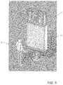
- FIG. 6illustrates a rendered view of two digital billboard devices 680 and provides an exemplary comparison in dimensions of the digital billboard devices 680 and an average adult human 90 .
- the digital billboard devices 680may include digital displays 682 (of which only one is visible in FIG. 6 ) that are several times larger than the average adult human 90 and that are positioned some distance above ground.
- the digital billboard devices 680may be mounted on a columnar mount, vertical pole, or the like, as demonstrated by mounting structure 630 .
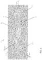
- FIG. 6 and in FIG. 7are components of a base station 610 .
- FIG. 7illustrates the base station 610 and mounting structure 630 , with the digital billboard devices 680 removed for clarity in understanding that which is concealed by the digital billboard devices.
- the small cell base station 10discussed above with reference to FIG. 7
- at least a portion of the base station 610is concealed by a concealment device, which in the case of the base station 610 are the digital billboard devices 680 themselves.
- the base station 610may include an antenna module 620 , which may in some aspects include a concealed antenna module.
- the antenna module 620may include one or more antennas, which collectively may have an omni-directional antenna pattern in the azimuth plane, meaning that the antenna beam generated by the one or more antennas of antenna module 620 may extend through a full 360 degree circle in the azimuth plane.
- each given antennamay generate an antenna beam which extends only through an arc portion of a full 360 degree circle.
- each antennamay have an antenna pattern of one-third of a full 360 degree circle in the azimuth plane, or a beam width of 120 degrees.
- Each antennamay have a suitable beamwidth (e.g., 10-30 degrees) in the elevation plane.
- the antenna beammay be slightly down-tilted in the elevation plane to reduce interference with adjacent base stations.
- the antenna modulemay be mounted at the top of the mounting structure 630 .
- mechanical downtilt devicesmay be used to angle one or more of the antennas of the antenna module 620 to provide downtilt.
- the base station 610may also include a radio 650 . Although illustrated as a single device, in some aspects multiple devices may be used.
- This radio 650may include base station equipment such as a radio, but may also include power and optical fiber components.
- the radio 650may include a radio/power/fiber module.
- a single radio 650is shown in FIG. 7 to simplify the drawing, but more than one radio may be provided.
- the radio 650may be a remote radio head that is mounted on mounting structure 630 .
- the radio 650may communicate (via optical fibers, coaxial cables, or the like) with a baseband unit 660 .
- the baseband unit 660may be mounted to the mounting structure 630 .
- Such a configurationmay be referred to as a “zero footprint” configuration, because the antenna module, radio, and baseband unit are each mounted to mounting structure 630 .
- the baseband unit 660may send and receive data to and from another source such as, for example, a backhaul network (not shown) and may process this data and provide a data stream to the radio 650 .
- the radio 650may generate RF signals that include the data encoded therein and may amplify and deliver these RF signals to the antenna module for transmission via respective cabling connections (not shown).
- a microwave backhaul radio and antennamay be included within the base station 610 .
- circuitryconfigured to convert signals between the microwave transmission path and the cellular transmission paths may be provided, although not shown in FIG. 7 .
- the small cell base station 610 of FIG. 7may include various other equipment such as, for example, a power supply, back-up batteries, a power bus, Antenna Interface Signal Group (“AISG”) controllers and the like which are not illustrated in FIG. 7 . In some aspects, these may be mounted at various locations on mounting structure 630 , or may be located within baseband unit 660 (which may include a cabinet). In some aspects, the base station 610 may be installed as a retro-fit module and/or as an add-on module atop an already installed digital billboard device 680 . In such aspects, that the base station 610 may be configured to receive operational power from the digital billboard devices 680 (for example, via a power connection available from mounting structure 630 and/or digital billboard device 680 ).
- ASGAntenna Interface Signal Group
- the digital billboard devices 680 and the base station 610may be powered in common, and the digital billboard devices 680 may act as a pass-through to empower the base station 610 .
- the base station 610may be a small cell base station, macrocell base station, or other base station.
- a digital billboard device 680may be, in some aspects, at least ten feet in height and at least thirty feet in width, although in other aspects, the display panel 681 may be at least fourteen feet in height and at least forty-eight feet in width. Such dimensions are merely exemplary.
Landscapes
- Engineering & Computer Science (AREA)
- Computer Networks & Wireless Communication (AREA)
- Signal Processing (AREA)
- Variable-Direction Aerials And Aerial Arrays (AREA)
- Support Of Aerials (AREA)
- Road Signs Or Road Markings (AREA)
- Mobile Radio Communication Systems (AREA)
Abstract
Description
Claims (12)
Priority Applications (3)
| Application Number | Priority Date | Filing Date | Title |
|---|---|---|---|
| US15/469,695US10749249B2 (en) | 2016-05-04 | 2017-03-27 | Display panel with integrated small cell and billboard with integrated macro site |
| US16/984,332US20200365975A1 (en) | 2016-05-04 | 2020-08-04 | Display panel with integrated small cell and billboard with integrated macro site |
| US18/500,301US20240145906A1 (en) | 2016-05-04 | 2023-11-02 | Display panel with integrated small cell and billboard with integrated macro site |
Applications Claiming Priority (2)
| Application Number | Priority Date | Filing Date | Title |
|---|---|---|---|
| US201662331695P | 2016-05-04 | 2016-05-04 | |
| US15/469,695US10749249B2 (en) | 2016-05-04 | 2017-03-27 | Display panel with integrated small cell and billboard with integrated macro site |
Related Child Applications (1)
| Application Number | Title | Priority Date | Filing Date |
|---|---|---|---|
| US16/984,332ContinuationUS20200365975A1 (en) | 2016-05-04 | 2020-08-04 | Display panel with integrated small cell and billboard with integrated macro site |
Publications (2)
| Publication Number | Publication Date |
|---|---|
| US20170324154A1 US20170324154A1 (en) | 2017-11-09 |
| US10749249B2true US10749249B2 (en) | 2020-08-18 |
Family
ID=60203377
Family Applications (3)
| Application Number | Title | Priority Date | Filing Date |
|---|---|---|---|
| US15/469,695ActiveUS10749249B2 (en) | 2016-05-04 | 2017-03-27 | Display panel with integrated small cell and billboard with integrated macro site |
| US16/984,332AbandonedUS20200365975A1 (en) | 2016-05-04 | 2020-08-04 | Display panel with integrated small cell and billboard with integrated macro site |
| US18/500,301PendingUS20240145906A1 (en) | 2016-05-04 | 2023-11-02 | Display panel with integrated small cell and billboard with integrated macro site |
Family Applications After (2)
| Application Number | Title | Priority Date | Filing Date |
|---|---|---|---|
| US16/984,332AbandonedUS20200365975A1 (en) | 2016-05-04 | 2020-08-04 | Display panel with integrated small cell and billboard with integrated macro site |
| US18/500,301PendingUS20240145906A1 (en) | 2016-05-04 | 2023-11-02 | Display panel with integrated small cell and billboard with integrated macro site |
Country Status (3)
| Country | Link |
|---|---|
| US (3) | US10749249B2 (en) |
| EP (2) | EP4404386A3 (en) |
| WO (1) | WO2017192731A1 (en) |
Families Citing this family (13)
| Publication number | Priority date | Publication date | Assignee | Title |
|---|---|---|---|---|
| EP3593541A4 (en)* | 2017-03-06 | 2021-04-07 | Commscope Technologies LLC | Modular monopole for wireless communications |
| CN107092151B (en)* | 2017-06-30 | 2020-01-10 | 上海天马微电子有限公司 | Array substrate, electronic paper type display panel, driving method of electronic paper type display panel and display device |
| CA3088868A1 (en)* | 2018-01-08 | 2019-07-11 | Ubicquia Llc | Camouflaged small cell networking devices |
| WO2019178502A2 (en) | 2018-03-15 | 2019-09-19 | Dimitrios Lalos | Multi-purpose smart tower |
| US12003016B2 (en)* | 2018-10-29 | 2024-06-04 | Commscope Technologies Llc | Perforated door for monopole module and method of mounting same |
| US11165161B2 (en) | 2019-01-18 | 2021-11-02 | Commscope Technologies Llc | Small cell base station integrated with storefront sign |
| WO2020251981A1 (en)* | 2019-06-14 | 2020-12-17 | Commscope Technologies Llc | Small cell antenna integrated with street sign |
| US11456528B2 (en) | 2020-04-21 | 2022-09-27 | Commscope Technologies Llc | Through-hole antenna mounts and assemblies |
| US11837772B2 (en)* | 2021-03-25 | 2023-12-05 | Commscope Technologies Llc | Modules for cellular base stations and bracket assemblies for mounting same |
| CN119111017A (en)* | 2021-08-15 | 2024-12-10 | 户外无线网络有限公司 | Base station antenna having at least one rotatable reflector panel suitable for sharing by multiple cellular network operators |
| US12035486B1 (en) | 2022-07-25 | 2024-07-09 | Manufacturing Resources International, Inc. | Electronic display assembly with fabric panel communications box |
| US12190462B2 (en)* | 2023-04-24 | 2025-01-07 | Arthur Jeppe | Systems and methods for rendering images |
| WO2025180729A1 (en)* | 2024-02-27 | 2025-09-04 | Commscope Design And Integration Uk Ltd. | Small cell base station integrated with storefront sign |
Citations (33)
| Publication number | Priority date | Publication date | Assignee | Title |
|---|---|---|---|---|
| US5049891A (en)* | 1990-02-23 | 1991-09-17 | Grumman Aerospace Corporation | Radome-antenna installation with rotating equipment rack |
| US5612741A (en)* | 1993-11-05 | 1997-03-18 | Curtis Mathes Marketing Corporation | Video billboard |
| CN2309600Y (en) | 1997-09-18 | 1999-03-03 | 林凡闵 | Combined advertising signboard structure device |
| US5926145A (en) | 1996-07-22 | 1999-07-20 | Nec Corporation | Base station for mobile communication |
| US6222503B1 (en) | 1997-01-10 | 2001-04-24 | William Gietema | System and method of integrating and concealing antennas, antenna subsystems and communications subsystems |
| US20040164911A1 (en)* | 2003-02-25 | 2004-08-26 | Jellent Sun | Portable electrical device with planar antenna |
| JP2005283889A (en) | 2004-03-29 | 2005-10-13 | Rebuilt Enterprise:Kk | Protruded signboard |
| US20050282586A1 (en)* | 2004-06-22 | 2005-12-22 | Rutherford Joe A | Elevated antenna and mounting structure in a wireless network |
| US20060070281A1 (en) | 2001-12-06 | 2006-04-06 | Passannante Caesar A | Illuminated advertising trash receptacle |
| US20080089288A1 (en)* | 2006-10-12 | 2008-04-17 | Bellsouth Intellectual Property Corporation | Methods, systems, and computer program products for providing advertising and/or information services over mobile ad hoc cooperative networks using electronic billboards and related devices |
| US20090135074A1 (en)* | 2007-11-26 | 2009-05-28 | Ching-Shun Yang | Single drive variable azimuth and beam tilt antenna for wireless network |
| US7671814B2 (en) | 2001-11-26 | 2010-03-02 | Itron, Inc. | Embedded antenna apparatus for utility metering applications |
| CN201515001U (en) | 2009-10-14 | 2010-06-23 | 中兴通讯股份有限公司 | Antenna stand capable of adjusting angle of antenna |
| US20100231469A1 (en) | 2009-03-10 | 2010-09-16 | Kmw Inc. | Antenna Device for Mobile Communication System |
| CN201918491U (en) | 2010-12-20 | 2011-08-03 | 惠州市海能天地通通信设备有限公司 | Wall-mounted square box type antenna of base station |
| CN202749055U (en) | 2012-03-31 | 2013-02-20 | 张可开 | Advertising lamp box |
| JP3185100U (en) | 2013-05-20 | 2013-08-01 | 日本サイン株式会社 | Box-shaped signboard device |
| CN203573598U (en) | 2013-11-19 | 2014-04-30 | 淀洋科技(定南)有限公司 | Ultra-thin double-sided light box with internally-arranged power source |
| US20140217248A1 (en)* | 2011-08-31 | 2014-08-07 | Mitsubishi Electric Corporation | Antenna apparatus |
| WO2014132233A2 (en) | 2013-02-28 | 2014-09-04 | Poynting Antennas (Pty) Limited | A method of and system for mounting an antenna in a wireless network |
| US20140267896A1 (en)* | 2013-03-16 | 2014-09-18 | ADTI Media, LLC | Field retrofit kit for converting a static billboard into a dynamic electronic billboard, and methods of retrofitting and using same |
| US20150031372A1 (en) | 2013-07-26 | 2015-01-29 | Jeffrey R. Foerster | Vehicle-based small cell base stations |
| CN204315209U (en) | 2014-12-10 | 2015-05-06 | 广州优游文化传播有限公司 | There is the lamp box of audio frequency and video playing function |
| US20150177374A1 (en) | 2013-12-23 | 2015-06-25 | Elwha Llc | Systems and methods for concealed radar imaging |
| CN204665082U (en) | 2015-06-04 | 2015-09-23 | 西安理想华夏科技创新有限公司 | A kind of advertisement road lamp with hotel information prompt facility |
| US20150303585A1 (en)* | 2014-04-18 | 2015-10-22 | Andrew Llc | Method of Forming Broad Radiation Patterns For Small-Cell Base Station Antennas |
| US20150349399A1 (en)* | 2014-05-30 | 2015-12-03 | Enersphere Communications Llc | Small cell communications pole, system, and method |
| US20150371571A1 (en)* | 2012-12-12 | 2015-12-24 | Telefonaktiebolaget L M Ericsson (Publ) | A Telecommunications Station Enclosure |
| WO2016040745A1 (en) | 2014-09-12 | 2016-03-17 | Commscope Technologies Llc | Aesthetically appealing communications equipment enclosure |
| US9781246B2 (en)* | 2015-08-28 | 2017-10-03 | Qualcomm Incorporated | Augmenting reality using a small cell |
| US20170352952A1 (en)* | 2015-02-24 | 2017-12-07 | Fraunhofer-Gesellschaft Zur Foerderung Der Angewandten Forschung E.V. | Integrated transceiver with focusing antenna |
| US20180062247A1 (en)* | 2016-08-25 | 2018-03-01 | Publicidad Exterior S.R.L. | Billboard with concealed antenna for cellular phone |
| US20180102833A1 (en)* | 2012-08-22 | 2018-04-12 | Maxlinear, Inc. | Method and system for caching content for mobile distribution |
Family Cites Families (4)
| Publication number | Priority date | Publication date | Assignee | Title |
|---|---|---|---|---|
| US6484148B1 (en)* | 2000-02-19 | 2002-11-19 | John E. Boyd | Electronic advertising device and method of using the same |
| US9014704B2 (en)* | 2013-03-15 | 2015-04-21 | Smartsky Networks LLC | Concentric cells in a wireless communication system |
| US9998200B2 (en)* | 2013-06-20 | 2018-06-12 | Aviat U.S., Inc. | Systems and methods for a fronthaul network |
| US9470782B2 (en)* | 2014-11-26 | 2016-10-18 | Valeo Radar Systems, Inc. | Method and apparatus for increasing angular resolution in an automotive radar system |
- 2017
- 2017-03-27USUS15/469,695patent/US10749249B2/enactiveActive
- 2017-05-03WOPCT/US2017/030854patent/WO2017192731A1/ennot_activeCeased
- 2017-05-03EPEP24163883.2Apatent/EP4404386A3/enactivePending
- 2017-05-03EPEP17793259.7Apatent/EP3482451A4/ennot_activeWithdrawn
- 2020
- 2020-08-04USUS16/984,332patent/US20200365975A1/ennot_activeAbandoned
- 2023
- 2023-11-02USUS18/500,301patent/US20240145906A1/enactivePending
Patent Citations (34)
| Publication number | Priority date | Publication date | Assignee | Title |
|---|---|---|---|---|
| US5049891A (en)* | 1990-02-23 | 1991-09-17 | Grumman Aerospace Corporation | Radome-antenna installation with rotating equipment rack |
| US5612741A (en)* | 1993-11-05 | 1997-03-18 | Curtis Mathes Marketing Corporation | Video billboard |
| US5926145A (en) | 1996-07-22 | 1999-07-20 | Nec Corporation | Base station for mobile communication |
| US6222503B1 (en) | 1997-01-10 | 2001-04-24 | William Gietema | System and method of integrating and concealing antennas, antenna subsystems and communications subsystems |
| CN2309600Y (en) | 1997-09-18 | 1999-03-03 | 林凡闵 | Combined advertising signboard structure device |
| US7671814B2 (en) | 2001-11-26 | 2010-03-02 | Itron, Inc. | Embedded antenna apparatus for utility metering applications |
| US20060070281A1 (en) | 2001-12-06 | 2006-04-06 | Passannante Caesar A | Illuminated advertising trash receptacle |
| US20040164911A1 (en)* | 2003-02-25 | 2004-08-26 | Jellent Sun | Portable electrical device with planar antenna |
| JP2005283889A (en) | 2004-03-29 | 2005-10-13 | Rebuilt Enterprise:Kk | Protruded signboard |
| US20050282586A1 (en)* | 2004-06-22 | 2005-12-22 | Rutherford Joe A | Elevated antenna and mounting structure in a wireless network |
| US20080089288A1 (en)* | 2006-10-12 | 2008-04-17 | Bellsouth Intellectual Property Corporation | Methods, systems, and computer program products for providing advertising and/or information services over mobile ad hoc cooperative networks using electronic billboards and related devices |
| US8254338B2 (en)* | 2006-10-12 | 2012-08-28 | At&T Intellectual Property I, L.P. | Methods, systems, and computer program products for providing advertising and/or information services over mobile ad hoc cooperative networks using electronic billboards and related devices |
| US20090135074A1 (en)* | 2007-11-26 | 2009-05-28 | Ching-Shun Yang | Single drive variable azimuth and beam tilt antenna for wireless network |
| US20100231469A1 (en) | 2009-03-10 | 2010-09-16 | Kmw Inc. | Antenna Device for Mobile Communication System |
| CN201515001U (en) | 2009-10-14 | 2010-06-23 | 中兴通讯股份有限公司 | Antenna stand capable of adjusting angle of antenna |
| CN201918491U (en) | 2010-12-20 | 2011-08-03 | 惠州市海能天地通通信设备有限公司 | Wall-mounted square box type antenna of base station |
| US20140217248A1 (en)* | 2011-08-31 | 2014-08-07 | Mitsubishi Electric Corporation | Antenna apparatus |
| CN202749055U (en) | 2012-03-31 | 2013-02-20 | 张可开 | Advertising lamp box |
| US20180102833A1 (en)* | 2012-08-22 | 2018-04-12 | Maxlinear, Inc. | Method and system for caching content for mobile distribution |
| US20150371571A1 (en)* | 2012-12-12 | 2015-12-24 | Telefonaktiebolaget L M Ericsson (Publ) | A Telecommunications Station Enclosure |
| WO2014132233A2 (en) | 2013-02-28 | 2014-09-04 | Poynting Antennas (Pty) Limited | A method of and system for mounting an antenna in a wireless network |
| US20140267896A1 (en)* | 2013-03-16 | 2014-09-18 | ADTI Media, LLC | Field retrofit kit for converting a static billboard into a dynamic electronic billboard, and methods of retrofitting and using same |
| JP3185100U (en) | 2013-05-20 | 2013-08-01 | 日本サイン株式会社 | Box-shaped signboard device |
| US20150031372A1 (en) | 2013-07-26 | 2015-01-29 | Jeffrey R. Foerster | Vehicle-based small cell base stations |
| CN203573598U (en) | 2013-11-19 | 2014-04-30 | 淀洋科技(定南)有限公司 | Ultra-thin double-sided light box with internally-arranged power source |
| US20150177374A1 (en) | 2013-12-23 | 2015-06-25 | Elwha Llc | Systems and methods for concealed radar imaging |
| US20150303585A1 (en)* | 2014-04-18 | 2015-10-22 | Andrew Llc | Method of Forming Broad Radiation Patterns For Small-Cell Base Station Antennas |
| US20150349399A1 (en)* | 2014-05-30 | 2015-12-03 | Enersphere Communications Llc | Small cell communications pole, system, and method |
| WO2016040745A1 (en) | 2014-09-12 | 2016-03-17 | Commscope Technologies Llc | Aesthetically appealing communications equipment enclosure |
| CN204315209U (en) | 2014-12-10 | 2015-05-06 | 广州优游文化传播有限公司 | There is the lamp box of audio frequency and video playing function |
| US20170352952A1 (en)* | 2015-02-24 | 2017-12-07 | Fraunhofer-Gesellschaft Zur Foerderung Der Angewandten Forschung E.V. | Integrated transceiver with focusing antenna |
| CN204665082U (en) | 2015-06-04 | 2015-09-23 | 西安理想华夏科技创新有限公司 | A kind of advertisement road lamp with hotel information prompt facility |
| US9781246B2 (en)* | 2015-08-28 | 2017-10-03 | Qualcomm Incorporated | Augmenting reality using a small cell |
| US20180062247A1 (en)* | 2016-08-25 | 2018-03-01 | Publicidad Exterior S.R.L. | Billboard with concealed antenna for cellular phone |
Non-Patent Citations (2)
| Title |
|---|
| Extended European Search Report issued in corresponding European Patent Application No. 17793259.7, dated Feb. 17, 2020 (9 pages). |
| Notification of Transmittal of the International Search Report and the Written Opinion of the International Searching Authority, or the Declaration corresponding to International Application No. PCT/US2017/030854; dated Aug. 8, 2017. |
Also Published As
| Publication number | Publication date |
|---|---|
| EP3482451A4 (en) | 2020-03-18 |
| EP4404386A3 (en) | 2024-10-09 |
| US20200365975A1 (en) | 2020-11-19 |
| EP3482451A1 (en) | 2019-05-15 |
| EP4404386A2 (en) | 2024-07-24 |
| WO2017192731A1 (en) | 2017-11-09 |
| US20240145906A1 (en) | 2024-05-02 |
| US20170324154A1 (en) | 2017-11-09 |
Similar Documents
| Publication | Publication Date | Title |
|---|---|---|
| US20240145906A1 (en) | Display panel with integrated small cell and billboard with integrated macro site | |
| US6222503B1 (en) | System and method of integrating and concealing antennas, antenna subsystems and communications subsystems | |
| US12294439B2 (en) | Meta-structure wireless infrastructure for beamforming systems | |
| US20150371571A1 (en) | A Telecommunications Station Enclosure | |
| US20040174317A1 (en) | Low visual impact monopole tower for wireless communications | |
| US12062854B2 (en) | Wireless communications system with scalable architecture | |
| US20210367331A1 (en) | Multi-Purpose Smart Tower | |
| US11258182B2 (en) | Meta-structure based reflectarrays for enhanced wireless applications | |
| US12300885B2 (en) | Small cell base station integrated with storefront sign | |
| US11223387B2 (en) | Small cell base station antennas suitable for strand mounting and related system architectures | |
| US11183773B2 (en) | Configurable communication system using stacked antennas | |
| WO2014132233A2 (en) | A method of and system for mounting an antenna in a wireless network | |
| WO2025180729A1 (en) | Small cell base station integrated with storefront sign | |
| WO2020219967A1 (en) | Configurable communication system using stacked antennas | |
| TWI677259B (en) | Street light apparatus | |
| CN210112001U (en) | Mobile base station equipment | |
| CZ186999A3 (en) | Ground communication system |
Legal Events
| Date | Code | Title | Description |
|---|---|---|---|
| AS | Assignment | Owner name:COMMSCOPE TECHNOLOGIES LLC, NORTH CAROLINA Free format text:ASSIGNMENT OF ASSIGNORS INTEREST;ASSIGNORS:HENDRIX, WALTER MARK;COLAPIETRO, JULIAN R.;MENDEZ, NAIARA NAFARRATE;AND OTHERS;SIGNING DATES FROM 20170328 TO 20170722;REEL/FRAME:043073/0335 | |
| STPP | Information on status: patent application and granting procedure in general | Free format text:RESPONSE TO NON-FINAL OFFICE ACTION ENTERED AND FORWARDED TO EXAMINER | |
| STPP | Information on status: patent application and granting procedure in general | Free format text:FINAL REJECTION MAILED | |
| AS | Assignment | Owner name:JPMORGAN CHASE BANK, N.A., NEW YORK Free format text:TERM LOAN SECURITY AGREEMENT;ASSIGNORS:COMMSCOPE, INC. OF NORTH CAROLINA;COMMSCOPE TECHNOLOGIES LLC;ARRIS ENTERPRISES LLC;AND OTHERS;REEL/FRAME:049905/0504 Effective date:20190404 Owner name:WILMINGTON TRUST, NATIONAL ASSOCIATION, AS COLLATE Free format text:PATENT SECURITY AGREEMENT;ASSIGNOR:COMMSCOPE TECHNOLOGIES LLC;REEL/FRAME:049892/0051 Effective date:20190404 Owner name:JPMORGAN CHASE BANK, N.A., NEW YORK Free format text:ABL SECURITY AGREEMENT;ASSIGNORS:COMMSCOPE, INC. OF NORTH CAROLINA;COMMSCOPE TECHNOLOGIES LLC;ARRIS ENTERPRISES LLC;AND OTHERS;REEL/FRAME:049892/0396 Effective date:20190404 Owner name:WILMINGTON TRUST, NATIONAL ASSOCIATION, AS COLLATERAL AGENT, CONNECTICUT Free format text:PATENT SECURITY AGREEMENT;ASSIGNOR:COMMSCOPE TECHNOLOGIES LLC;REEL/FRAME:049892/0051 Effective date:20190404 | |
| STPP | Information on status: patent application and granting procedure in general | Free format text:DOCKETED NEW CASE - READY FOR EXAMINATION | |
| STPP | Information on status: patent application and granting procedure in general | Free format text:NON FINAL ACTION MAILED | |
| STCV | Information on status: appeal procedure | Free format text:NOTICE OF APPEAL FILED | |
| STPP | Information on status: patent application and granting procedure in general | Free format text:NOTICE OF ALLOWANCE MAILED -- APPLICATION RECEIVED IN OFFICE OF PUBLICATIONS | |
| STPP | Information on status: patent application and granting procedure in general | Free format text:PUBLICATIONS -- ISSUE FEE PAYMENT VERIFIED | |
| STCF | Information on status: patent grant | Free format text:PATENTED CASE | |
| AS | Assignment | Owner name:WILMINGTON TRUST, DELAWARE Free format text:SECURITY INTEREST;ASSIGNORS:ARRIS SOLUTIONS, INC.;ARRIS ENTERPRISES LLC;COMMSCOPE TECHNOLOGIES LLC;AND OTHERS;REEL/FRAME:060752/0001 Effective date:20211115 | |
| MAFP | Maintenance fee payment | Free format text:PAYMENT OF MAINTENANCE FEE, 4TH YEAR, LARGE ENTITY (ORIGINAL EVENT CODE: M1551); ENTITY STATUS OF PATENT OWNER: LARGE ENTITY Year of fee payment:4 | |
| AS | Assignment | Owner name:OUTDOOR WIRELESS NETWORKS LLC, NORTH CAROLINA Free format text:ASSIGNMENT OF ASSIGNORS INTEREST;ASSIGNOR:COMMSCOPE TECHNOLOGIES LLC;REEL/FRAME:068107/0089 Effective date:20240701 | |
| AS | Assignment | Owner name:JPMORGAN CHASE BANK, N.A., AS COLLATERAL AGENT, NEW YORK Free format text:PATENT SECURITY AGREEMENT (TERM);ASSIGNOR:OUTDOOR WIRELESS NETWORKS LLC;REEL/FRAME:068770/0632 Effective date:20240813 Owner name:JPMORGAN CHASE BANK, N.A., AS COLLATERAL AGENT, NEW YORK Free format text:PATENT SECURITY AGREEMENT (ABL);ASSIGNOR:OUTDOOR WIRELESS NETWORKS LLC;REEL/FRAME:068770/0460 Effective date:20240813 | |
| AS | Assignment | Owner name:APOLLO ADMINISTRATIVE AGENCY LLC, NEW YORK Free format text:SECURITY INTEREST;ASSIGNORS:ARRIS ENTERPRISES LLC;COMMSCOPE TECHNOLOGIES LLC;COMMSCOPE INC., OF NORTH CAROLINA;AND OTHERS;REEL/FRAME:069889/0114 Effective date:20241217 | |
| AS | Assignment | Owner name:OUTDOOR WIRELESS NETWORKS LLC, NORTH CAROLINA Free format text:RELEASE OF SECURITY INTEREST AT REEL/FRAME 068770/0632;ASSIGNOR:JPMORGAN CHASE BANK, N.A., AS COLLATERAL AGENT;REEL/FRAME:069743/0264 Effective date:20241217 Owner name:RUCKUS WIRELESS, LLC (F/K/A RUCKUS WIRELESS, INC.), NORTH CAROLINA Free format text:RELEASE OF SECURITY INTEREST AT REEL/FRAME 049905/0504;ASSIGNOR:JPMORGAN CHASE BANK, N.A., AS COLLATERAL AGENT;REEL/FRAME:071477/0255 Effective date:20241217 Owner name:COMMSCOPE TECHNOLOGIES LLC, NORTH CAROLINA Free format text:RELEASE OF SECURITY INTEREST AT REEL/FRAME 049905/0504;ASSIGNOR:JPMORGAN CHASE BANK, N.A., AS COLLATERAL AGENT;REEL/FRAME:071477/0255 Effective date:20241217 Owner name:COMMSCOPE, INC. OF NORTH CAROLINA, NORTH CAROLINA Free format text:RELEASE OF SECURITY INTEREST AT REEL/FRAME 049905/0504;ASSIGNOR:JPMORGAN CHASE BANK, N.A., AS COLLATERAL AGENT;REEL/FRAME:071477/0255 Effective date:20241217 Owner name:ARRIS SOLUTIONS, INC., NORTH CAROLINA Free format text:RELEASE OF SECURITY INTEREST AT REEL/FRAME 049905/0504;ASSIGNOR:JPMORGAN CHASE BANK, N.A., AS COLLATERAL AGENT;REEL/FRAME:071477/0255 Effective date:20241217 Owner name:ARRIS TECHNOLOGY, INC., NORTH CAROLINA Free format text:RELEASE OF SECURITY INTEREST AT REEL/FRAME 049905/0504;ASSIGNOR:JPMORGAN CHASE BANK, N.A., AS COLLATERAL AGENT;REEL/FRAME:071477/0255 Effective date:20241217 Owner name:ARRIS ENTERPRISES LLC (F/K/A ARRIS ENTERPRISES, INC.), NORTH CAROLINA Free format text:RELEASE OF SECURITY INTEREST AT REEL/FRAME 049905/0504;ASSIGNOR:JPMORGAN CHASE BANK, N.A., AS COLLATERAL AGENT;REEL/FRAME:071477/0255 Effective date:20241217 | |
| AS | Assignment | Owner name:OUTDOOR WIRELESS NETWORKS LLC, NORTH CAROLINA Free format text:PARTIAL TERMINATION AND RELEASE OF SECURITY INTEREST IN PATENTS RECORDED AT REEL 069889/FRAME 0114;ASSIGNOR:APOLLO ADMINISTRATIVE AGENCY LLC;REEL/FRAME:070154/0341 Effective date:20250131 Owner name:OUTDOOR WIRELESS NETWORKS LLC, NORTH CAROLINA Free format text:PARTIAL TERMINATION AND RELEASE OF SECURITY INTEREST IN PATENTS;ASSIGNOR:U.S. BANK TRUST COMPANY, NATIONAL ASSOCIATION;REEL/FRAME:070154/0183 Effective date:20250131 Owner name:OUTDOOR WIRELESS NETWORKS LLC, NORTH CAROLINA Free format text:RELEASE (REEL 068770 / FRAME 0460);ASSIGNOR:JPMORGAN CHASE BANK, N.A.;REEL/FRAME:070149/0432 Effective date:20250131 |