US10747618B2 - Checkpointing of metadata into user data area of a content addressable storage system - Google Patents
Checkpointing of metadata into user data area of a content addressable storage systemDownload PDFInfo
- Publication number
- US10747618B2 US10747618B2US16/202,831US201816202831AUS10747618B2US 10747618 B2US10747618 B2US 10747618B2US 201816202831 AUS201816202831 AUS 201816202831AUS 10747618 B2US10747618 B2US 10747618B2
- Authority
- US
- United States
- Prior art keywords
- metadata
- location
- array
- page
- user data
- Prior art date
- Legal status (The legal status is an assumption and is not a legal conclusion. Google has not performed a legal analysis and makes no representation as to the accuracy of the status listed.)
- Active, expires
Links
Images


Classifications
- G—PHYSICS
- G06—COMPUTING OR CALCULATING; COUNTING
- G06F—ELECTRIC DIGITAL DATA PROCESSING
- G06F11/00—Error detection; Error correction; Monitoring
- G06F11/07—Responding to the occurrence of a fault, e.g. fault tolerance
- G06F11/14—Error detection or correction of the data by redundancy in operation
- G06F11/1402—Saving, restoring, recovering or retrying
- G06F11/1405—Saving, restoring, recovering or retrying at machine instruction level
- G06F11/1407—Checkpointing the instruction stream
- G—PHYSICS
- G06—COMPUTING OR CALCULATING; COUNTING
- G06F—ELECTRIC DIGITAL DATA PROCESSING
- G06F11/00—Error detection; Error correction; Monitoring
- G06F11/07—Responding to the occurrence of a fault, e.g. fault tolerance
- G06F11/14—Error detection or correction of the data by redundancy in operation
- G06F11/1402—Saving, restoring, recovering or retrying
- G06F11/1446—Point-in-time backing up or restoration of persistent data
- G—PHYSICS
- G06—COMPUTING OR CALCULATING; COUNTING
- G06F—ELECTRIC DIGITAL DATA PROCESSING
- G06F3/00—Input arrangements for transferring data to be processed into a form capable of being handled by the computer; Output arrangements for transferring data from processing unit to output unit, e.g. interface arrangements
- G06F3/06—Digital input from, or digital output to, record carriers, e.g. RAID, emulated record carriers or networked record carriers
- G06F3/0601—Interfaces specially adapted for storage systems
- G06F3/0602—Interfaces specially adapted for storage systems specifically adapted to achieve a particular effect
- G06F3/0614—Improving the reliability of storage systems
- G06F3/0619—Improving the reliability of storage systems in relation to data integrity, e.g. data losses, bit errors
- G—PHYSICS
- G06—COMPUTING OR CALCULATING; COUNTING
- G06F—ELECTRIC DIGITAL DATA PROCESSING
- G06F3/00—Input arrangements for transferring data to be processed into a form capable of being handled by the computer; Output arrangements for transferring data from processing unit to output unit, e.g. interface arrangements
- G06F3/06—Digital input from, or digital output to, record carriers, e.g. RAID, emulated record carriers or networked record carriers
- G06F3/0601—Interfaces specially adapted for storage systems
- G06F3/0628—Interfaces specially adapted for storage systems making use of a particular technique
- G06F3/0646—Horizontal data movement in storage systems, i.e. moving data in between storage devices or systems
- G06F3/065—Replication mechanisms
- G—PHYSICS
- G06—COMPUTING OR CALCULATING; COUNTING
- G06F—ELECTRIC DIGITAL DATA PROCESSING
- G06F3/00—Input arrangements for transferring data to be processed into a form capable of being handled by the computer; Output arrangements for transferring data from processing unit to output unit, e.g. interface arrangements
- G06F3/06—Digital input from, or digital output to, record carriers, e.g. RAID, emulated record carriers or networked record carriers
- G06F3/0601—Interfaces specially adapted for storage systems
- G06F3/0668—Interfaces specially adapted for storage systems adopting a particular infrastructure
- G06F3/067—Distributed or networked storage systems, e.g. storage area networks [SAN], network attached storage [NAS]
- G—PHYSICS
- G06—COMPUTING OR CALCULATING; COUNTING
- G06F—ELECTRIC DIGITAL DATA PROCESSING
- G06F3/00—Input arrangements for transferring data to be processed into a form capable of being handled by the computer; Output arrangements for transferring data from processing unit to output unit, e.g. interface arrangements
- G06F3/06—Digital input from, or digital output to, record carriers, e.g. RAID, emulated record carriers or networked record carriers
- G06F3/0601—Interfaces specially adapted for storage systems
- G06F3/0668—Interfaces specially adapted for storage systems adopting a particular infrastructure
- G06F3/0671—In-line storage system
- G06F3/0683—Plurality of storage devices
- G06F3/0689—Disk arrays, e.g. RAID, JBOD
- G—PHYSICS
- G06—COMPUTING OR CALCULATING; COUNTING
- G06F—ELECTRIC DIGITAL DATA PROCESSING
- G06F2201/00—Indexing scheme relating to error detection, to error correction, and to monitoring
- G06F2201/84—Using snapshots, i.e. a logical point-in-time copy of the data
Definitions
- the fieldrelates generally to information processing systems, and more particularly to storage in information processing systems.
- Storage systemsare often configured to generate periodic checkpoints in order to capture the state of the system at corresponding points in time.
- Such a checkpointing arrangementallows the system state to be recovered from a previously-captured checkpoint in the event of a storage device failure or other issue arising at a later point in time.
- conventional checkpointing arrangementscan be highly inefficient when capturing and recovering metadata in a content addressable storage system under certain conditions.
- Illustrative embodimentsprovide checkpointing of metadata into a user data area in a content addressable storage system. Such embodiments can advantageously provide significantly improved efficiency in checkpoint capture and recovery in a content addressable storage system in situations in which checkpointed metadata is stored in a user data area due to size limitations or other availability restrictions relating to a metadata area of the storage system. Similar advantages can be provided in other types of storage systems.
- an apparatuscomprises at least one processing device comprising a processor coupled to a memory.
- the processing deviceis configured to capture metadata from a metadata area of a storage system for checkpointing, and to store the captured metadata as checkpointed metadata in a user data area of the storage system in association with mapping information relating portions of the checkpointed metadata to particular storage locations in the user data area.
- the processing devicein some embodiments is implemented within the storage system, and may comprise a storage controller of the storage system.
- the mapping informationillustratively comprises a plurality of page location arrays each having a plurality of entries specifying respective locations of checkpointed metadata pages in the user data area.
- the mapping informationmay further comprise one or more array location arrays each indexed by a corresponding set of page location array identifiers specifying respective locations of page location arrays in the user data area.
- the mapping informationmay still further comprise locations of respective ones of a plurality of the array location arrays in the user data area.
- the locations of the respective ones of the array location arraysmay be stored as part of a checkpoint object for the checkpoint in a system memory of the storage system.
- one or more higher-level location arraysmay be used to store the locations of the respective ones of the array location arrays.
- the page location arraysmay be referred to as “level 0” arrays
- the array location arraysmay be referred to as “level 1” location arrays
- a given one of the higher-level location arrays used to store locations of respective ones of the array location arraysmay be referred to as a “level 2” location array.
- One or more of the level 2 location arraysmay be stored in the system memory as part of the above-noted checkpoint object.
- the storage systemcomprises a content addressable storage system and the metadata comprises hash metadata providing a mapping between content-based digests of respective pages of the user data and corresponding physical locations of the respective pages of the user data in the user data area.
- the storage devices in some embodimentscomprise non-volatile memory devices.
- the storage devices in such embodimentscan be configured to collectively provide an all-flash storage array.
- the storage systemmay comprise a clustered storage system having a plurality of storage nodes each having a plurality of storage devices.
- the storage controllermay be implemented in a distributed manner so as to comprise a plurality of distributed storage controller components implemented on respective ones of the storage nodes of the clustered storage system. Numerous other storage system arrangements are possible in other embodiments.
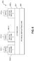
- FIG. 1is a block diagram of an information processing system comprising a content addressable storage system configured for generation of checkpoints including checkpointing of metadata into a user data area in an illustrative embodiment.
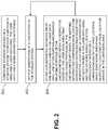
- FIG. 2is a flow diagram of a process for checkpointing metadata into a user data area in conjunction with generation of a checkpoint in a content addressable storage system in an illustrative embodiment.
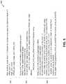
- FIG. 3shows an example of a page location array having a plurality of entries specifying respective locations of checkpointed metadata pages in a user data area in an illustrative embodiment.
- FIG. 4shows an example of an array location array indexed by a corresponding set of page location array identifiers specifying respective locations of page location arrays in a user data area in an illustrative embodiment.
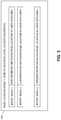
- FIG. 5shows example pseudocode for storing and recovering checkpointed metadata in a user data area using level 0, level 1 and level 2 location arrays in a content addressable storage system in an illustrative embodiment.
- FIGS. 6 and 7show examples of processing platforms that may be utilized to implement at least a portion of an information processing system in illustrative embodiments.
- ilustrarative embodimentswill be described herein with reference to exemplary information processing systems and associated computers, servers, storage devices and other processing devices. It is to be appreciated, however, that these and other embodiments are not restricted to the particular illustrative system and device configurations shown. Accordingly, the term “information processing system” as used herein is intended to be broadly construed, so as to encompass, for example, processing systems comprising cloud computing and storage systems, as well as other types of processing systems comprising various combinations of physical and virtual processing resources. An information processing system may therefore comprise, for example, at least one data center or other cloud-based system that includes one or more clouds hosting multiple tenants that share cloud resources. Numerous other types of enterprise computing and storage systems are also encompassed by the term “information processing system” as that term is broadly used herein.
- FIG. 1shows an information processing system 100 configured in accordance with an illustrative embodiment.
- the information processing system 100comprises a computer system 101 that includes compute nodes 102 - 1 , 102 - 2 , . . . 102 -N.
- the compute nodes 102communicate over a network 104 with a content addressable storage system 105 .
- the computer system 101is assumed to comprise an enterprise computer system or other arrangement of multiple compute nodes associated with respective users.
- the compute nodes 102illustratively comprise respective processing devices of one or more processing platforms.
- the compute nodes 102can comprise respective virtual machines (VMs) each having a processor and a memory, although numerous other configurations are possible.
- VMsvirtual machines
- the compute nodes 102can additionally or alternatively be part of cloud infrastructure such as an Amazon Web Services (AWS) system.
- AWSAmazon Web Services
- Other examples of cloud-based systems that can be used to provide compute nodes 102 and possibly other portions of system 100include Google Cloud Platform (GCP) and Microsoft Azure.
- GCPGoogle Cloud Platform
- AzureMicrosoft Azure
- the compute nodes 102in some embodiments illustratively provide compute services such as execution of one or more applications on behalf of each of one or more users associated with respective ones of the compute nodes 102 .
- Compute and/or storage servicesmay be provided for users under a platform-as-a-service (PaaS) model, although it is to be appreciated that numerous other cloud infrastructure arrangements could be used. Also, illustrative embodiments can be implemented outside of the cloud infrastructure context, as in the case of a stand-alone enterprise-based computing and storage system.
- PaaSplatform-as-a-service
- the network 104is assumed to comprise a portion of a global computer network such as the Internet, although other types of networks can be part of the network 104 , including a wide area network (WAN), a local area network (LAN), a satellite network, a telephone or cable network, a cellular network, a wireless network such as a WiFi or WiMAX network, or various portions or combinations of these and other types of networks.
- the network 104in some embodiments therefore comprises combinations of multiple different types of networks each comprising processing devices configured to communicate using IP or other communication protocols.
- some embodimentsmay utilize one or more high-speed local networks in which associated processing devices communicate with one another utilizing Peripheral Component Interconnect express (PCIe) cards of those devices, and networking protocols such as InfiniBand, Gigabit Ethernet or Fibre Channel.
- PCIePeripheral Component Interconnect express
- Numerous alternative networking arrangementsare possible in a given embodiment, as will be appreciated by those skilled in the art.
- the content addressable storage system 105is accessible to the compute nodes 102 of the computer system 101 over the network 104 .
- the content addressable storage system 105comprises a plurality of storage devices 106 and an associated storage controller 108 .
- the storage devices 106are configured to provide a metadata area 110 and a user data area 112 . It is assumed that the user data area 112 is separated into pages.
- the metadata area 110may be similarly separated into pages.
- a given “page” as the term is broadly used hereinshould not be viewed as being limited to any particular range of fixed sizes.
- a page size of 8 kilobytes (KB)is used, but this is by way of example only and can be varied in other embodiments. Accordingly, illustrative embodiments can utilize any of a wide variety of alternative paging arrangements for organizing the metadata area 110 and the user data area 112 .
- the user data area 112illustratively comprises a plurality of logical units (LUNs) configured to store files, blocks, objects or other arrangements of data on behalf of users associated with compute nodes 102 . Each such LUN may comprise particular ones of the above-noted pages of the user data area 112 .
- the user data stored in the user data area 112can include any type of user data that may be utilized in the system 100 .
- the term “user data” hereinis therefore also intended to be broadly construed.
- the storage devices 106comprise solid state drives (SSDs). Such SSDs are implemented using non-volatile memory (NVM) devices such as flash memory. Other types of NVM devices that can be used to implement at least a portion of the storage devices 106 include non-volatile random access memory (NVRAM), phase-change RAM (PC-RAM) and magnetic RAM (MRAM). Various combinations of multiple different types of NVM devices may also be used.
- SSDssolid state drives
- NVMnon-volatile memory
- NVRAMnon-volatile random access memory
- PC-RAMphase-change RAM
- MRAMmagnetic RAM
- Various combinations of multiple different types of NVM devicesmay also be used.
- a given storage system as the term is broadly used hereincan include a combination of different types of storage devices, as in the case of a multi-tier storage system comprising a flash-based fast tier and a disk-based capacity tier.
- each of the fast tier and the capacity tier of the multi-tier storage systemcomprises a plurality of storage devices with different types of storage devices being used in different ones of the storage tiers.
- the fast tiermay comprise flash drives while the capacity tier comprises hard disk drives.
- the particular storage devices used in a given storage tiermay be varied in other embodiments, and multiple distinct storage device types may be used within a single storage tier.
- storage deviceas used herein is intended to be broadly construed, so as to encompass, for example, flash drives, solid state drives, hard disk drives, hybrid drives or other types of storage devices.
- the content addressable storage system 105illustratively comprises a scale-out all-flash storage array such as an XtremIOTM storage array from Dell EMC of Hopkinton, Mass.
- a scale-out all-flash storage arraysuch as an XtremIOTM storage array from Dell EMC of Hopkinton, Mass.
- Other types of storage arraysincluding by way of example VNX® and Symmetrix VMAX® storage arrays also from Dell EMC, can be used to implement storage systems in other embodiments.
- storage systemas used herein is therefore intended to be broadly construed, and should not be viewed as being limited to content addressable storage systems or flash-based storage systems.
- a given storage system as the term is broadly used hereincan comprise, for example, network-attached storage (NAS), storage area networks (SANs), direct-attached storage (DAS) and distributed DAS, as well as combinations of these and other storage types, including software-defined storage.
- NASnetwork-attached storage
- SANsstorage area networks
- DASdirect-attached storage
- distributed DASdistributed DAS
- FIG. 1A block diagram illustrating an exemplary computing environment in accordance with an illustrative embodiment.
- FIG. 1A block diagram illustrating an exemplary computing environment in accordance with an illustrative embodiment.
- FIG. 1A block diagram illustrating an exemplary computing environment in accordance with an illustrative embodiment.
- FIG. 1A block diagram illustrating an exemplary computing environment in accordance with an illustrative embodiment.
- FIG. 1AOL-Voltage
- FIG. 1A block diagram illustrating an exemplary computing environment in accordance with an exemplary computing environment in accordance with an illustrative embodiment.
- FIG. 1A block diagram illustrating an exemplary computing environment in accordance with an exemplary computing environment in accordance with an exemplary computing environment in accordance with an illustrative embodiment.
- FIG. 1A block diagram illustrating an exemplary computing environment in accordance with an exemplary computing environment in accordance with an exemplary computing environment in accordance with an illustrative embodiment.
- FIG. 1A block diagram illustrating an
- the content addressable storage system 105 in the embodiment of FIG. 1is configured to generate hash metadata providing a mapping between content-based digests of respective pages of user data and corresponding physical locations of the respective pages of the user data in the user data area 112 .
- the hash metadata generated by the content addressable storage system 105is illustratively stored in the metadata area 110 .
- the generation and storage of the hash metadatais assumed to be performed under the control of the storage controller 108 .
- the hash metadatamay be stored in the metadata area 110 in a plurality of entries corresponding to respective buckets each comprising multiple cache lines, although other arrangements can be used.
- checkpointing arrangementscan be highly inefficient when capturing and recovering metadata in a content addressable storage system under certain conditions. For example, it may be desirable to take periodic checkpoints of at least portions of the metadata stored in the metadata area 110 . However, size limitations or other availability restrictions relating to the metadata area 110 may prevent such metadata checkpoints from being stored in the metadata area 110 . Under these and other conditions, it may be necessary to store the checkpointed metadata in the user data area 112 as part of the checkpointed metadata 114 .
- the present embodimentis configured with multi-level location arrays 116 that overcome inefficiencies and other difficulties that would otherwise be associated with checkpointing of metadata into a user data area.
- the pages of the user data areamay have a fixed size on the order of kilobytes.
- This page sizeis typically multiple orders of magnitude less than a total size of the checkpointed metadata which may be on the order of gigabytes.
- multi-level location arrays 116 of the user data area 112are used to efficiently track the particular page locations of checkpointed metadata 114 within the user data area 112 .
- such an embodimentcan advantageously provide significantly improved efficiency in checkpoint capture and recovery in a content addressable storage system in situations in which checkpointed metadata is stored in a user data area due to size limitations or other availability restrictions relating to a metadata area of the storage system.
- the multi-level location arrays 116 in the present embodimentare assumed to more particularly comprise a plurality of page location arrays each having a plurality of entries specifying respective locations of checkpointed metadata pages in the user data area 112 , and one or more array location arrays each indexed by a corresponding set of page location array identifiers specifying respective locations of page location arrays in the user data area 112 .
- Example configurations of a page location array and an array location arrayare shown in FIGS. 3 and 4 , respectively.
- the multi-level location arrays 116may further comprise one or more higher-level location arrays used to store the locations of the respective ones of the array location arrays.
- the page location arraysmay be referred to as “level 0” arrays
- the array location arraysmay be referred to as “level 1” location arrays
- a given one of the higher-level location arrays used to store locations of respective ones of the array location arraysmay be referred to as a “level 2” location array.
- Example pseudocode for storing and recovering checkpointed metadata using three different levels of location arrayswill be described below in conjunction with FIG. 5 .
- the storage controller 108 of the FIG. 1 embodimentis configured to initiate generation of checkpoints in the content addressable storage system 105 .
- Thisillustratively includes checkpointing of metadata stored in the metadata area 110 .
- the storage controller 108causes checkpointed metadata from the metadata area 110 to be stored in the user data area 112 .
- the storage controller 108further stores mapping information relating portions of the checkpointed metadata 114 to respective pages of the user data area 112 that store those portions of the checkpointed metadata 114 .
- This mapping informationillustratively comprises the multi-level location arrays 116 , including the plurality of page location arrays and the one or more array location arrays mentioned previously, and possibly one or more additional higher-level location arrays. Accordingly, the multi-level location arrays 116 collectively comprise one possible type of “mapping information” as that term is broadly used herein.
- the mapping informationcan therefore specify locations of respective ones of a plurality of the array location arrays in the user data area 112 .
- the locations of the respective ones of the array location arrayscan be stored in at least one of a checkpoint object for the given checkpoint in a system memory of the storage system.
- a system memory storing checkpoint objectsmay be separate from the storage devices 106 .
- the system memorymay illustratively comprise a central database used for storage of critical metadata in the content addressable storage system 105 .
- the locations of the respective ones of the array location arrayscan be stored using one or more higher-level location arrays as mentioned previously.
- one or more such higher-level location arrayscan be stored as part of the checkpoint object in the system memory.
- SYMis used in some embodiments to denote a system-wide management module comprising or otherwise having access to the above-noted system memory for storage of critical metadata.
- the SYMmay be part of the storage controller 108 or part of a given distributed component thereof in a distributed controller arrangement.
- checkpointas the term is broadly used herein can be an online system checkpoint or other type of checkpoint. It may be performed in accordance with a periodic checkpointing schedule or on demand, or under other conditions.
- the computer system 101 and content addressable storage system 105 in the FIG. 1 embodimentare assumed to be implemented using at least one processing platform each comprising one or more processing devices each having a processor coupled to a memory.
- processing devicescan illustratively include particular arrangements of compute, storage and network resources.
- processing devices in some embodimentsare implemented at least in part utilizing virtual resources such as VMs or Linux containers (LXCs), or combinations of both as in an arrangement in which Docker containers or other types of LXCs are configured to run on VMs.
- virtual resourcessuch as VMs or Linux containers (LXCs), or combinations of both as in an arrangement in which Docker containers or other types of LXCs are configured to run on VMs.
- the storage controller 108can be implemented in the form of one or more LXCs running on one or more VMs. Other arrangements of one or more processing devices of a processing platform can be used to implement the storage controller 108 . Other portions of the system 100 can similarly be implemented using one or more processing devices of at least one processing platform.
- the computer system 101 and the content addressable storage system 105may be implemented on respective distinct processing platforms, although numerous other arrangements are possible. For example, in some embodiments at least portions of the computer system 101 and the content addressable storage system 105 are implemented on the same processing platform.
- the content addressable storage system 105can therefore be implemented at least in part within at least one processing platform that implements at least a subset of the compute nodes 102 .
- processing platformas used herein is intended to be broadly construed so as to encompass, by way of illustration and without limitation, multiple sets of processing devices and associated storage systems that are configured to communicate over one or more networks.
- distributed implementations of the system 100are possible, in which certain components of the system reside in one data center in a first geographic location while other components of the cluster reside in one or more other data centers in one or more other geographic locations that are potentially remote from the first geographic location.
- Numerous other distributed implementations of one or both of the computer system 101 and the content addressable storage system 105are possible. Accordingly, the content addressable storage system 105 can also be implemented in a distributed manner across multiple data centers.
- the storage systemcomprises a clustered storage system having a plurality of storage nodes each having a plurality of storage devices.
- the content addressable storage system 105may represent a single storage node of such a clustered storage system. Alternatively, the content addressable storage system 105 may represent multiple storage nodes.
- the system 100 as illustrated in FIG. 1comprises additional storage nodes 120 that together with the content addressable storage system 105 form a clustered storage system.
- Each of the storage nodes of such a systemmay include separate instances of the storage controller 108 , metadata area 110 and user data area 112 .
- the storage controller 108may be implemented in a distributed manner so as to comprise a plurality of distributed storage controller components implemented on respective ones of the storage nodes of the clustered storage system.
- the storage controller 108in other embodiments can be implemented at least in part within the computer system 101 , in another system component, or as a stand-alone component coupled to the network 104 .
- system componentssuch as computer system 101 , compute nodes 102 , network 104 , content addressable storage system 105 , storage devices 106 , storage controller 108 , metadata area 110 and user data area 112 can be used in other embodiments.
- a given content addressable storage system or other type of storage system with functionality for checkpointing of metadata in a user data areacan be offered to cloud infrastructure customers or other users as a PaaS offering.
- step 200storage devices of a storage system are configured to provide a metadata area and a user data area, with the user data area being separated into pages.
- step 202generation of a checkpoint is initiated in the storage system. It is assumed that the checkpoint to be generated involves checkpointing of at least a portion of the metadata of the storage system into a user data area of the storage system.
- step 204checkpointed metadata from the metadata area is stored in the user data area, and mapping information relating portions of the checkpointed metadata to respective pages of the user data area that store those portions of the checkpointed metadata is also stored.
- the mapping informationis illustratively also stored in the user data area, but in other embodiments could be stored in other parts of the storage system.
- the mapping informationcomprises a plurality of page location arrays each having a plurality of entries specifying respective locations of checkpointed metadata pages in the user data area, and one or more array location arrays each indexed by a corresponding set of page location array identifiers specifying respective locations of page location arrays in the user data area.
- FIG. 3An example of a page location array 300 having a plurality of entries specifying respective locations of checkpointed metadata pages in the user data area is shown in FIG. 3 .
- the page location array 300also denoted as Page Location Array 1 , is one of a plurality of “level 0” location arrays that are stored in conjunction with the checkpointing of pages of the metadata into respective locations in the user data area.
- the page location array 300includes a plurality of entries, denoted by respective entry indexes Entry Index 1, Entry Index 2, . . . Entry Index n. These entries specify locations of respective checkpointed metadata page locations in the user data area.
- the stored mapping informationwill generally include multiple such page location arrays, each including a different set of entries for a corresponding different set of checkpointed metadata pages.
- the checkpointed metadata pages in this particular embodimentare generally stored in order of page identifier. Accordingly, page identifiers of the respective checkpointed metadata pages can be inferred from the entry indexes of the page location array.
- the entry indexesmay comprise respective unique page identifiers for the checkpointed metadata pages.
- the page identifiers of the checkpointed metadata pagesare explicitly stored with the respective locations of the checkpointed metadata pages in the page location arrays.
- FIG. 4An example of an array location array 400 indexed by a corresponding set of page location array identifiers specifying respective locations of page location arrays in the user data area is shown in FIG. 4 .
- the array location array 400also denoted as Array Location Array 1 , is one of a plurality of “level 1” location arrays that are stored in conjunction with the checkpointing of pages of the metadata into respective locations in the user data area.
- the array location array 400includes a plurality of entries relating respective unique page location array identifiers, denoted Array ID 1, Array ID 2, . . . Array ID m, to their respective storage locations in the user data area.
- the stored mapping informationwill generally include one or more such array location arrays, each including a different set of entries for a corresponding different set of page location arrays each configured as shown in FIG. 3 .
- the array identifiers utilized in FIG. 4can comprise respective entry indexes, configured in a manner similar to the entry indexes utilized in the page location array 300 of FIG. 3 .
- the term “array identifier” as used hereinis intended to be broadly construed so as to encompass an entry index corresponding to storage location information for a particular location array.
- the mapping informationmay further comprise one or more higher-level location arrays, at level 2 or above.
- the mapping informationmay further comprise one or more higher-level location arrays, at level 2 or above.
- location array configurations illustrated in FIGS. 3 and 4are presented by way of example only, and should not be construed as limiting in any way. Other types of location arrays can be used in other embodiments. Also, the term “array” as used herein is intended to be broadly construed so as to encompass a table or other type of data structure in which entry indexes or other types of entry identifiers can be associated with respective storage locations.
- Steps 202 and 204 of the FIG. 2 processcan be repeatedly iterated as needed, as indicated by the feedback arrow from step 204 to step 202 in the figure.
- the storage controller 108 of content addressable storage system 105is configured to store mapping information comprising multi-level location arrays 116 characterizing locations of respective pages of checkpointed metadata 114 within the user data area 112 .
- the storage controller 108in such an embodiment therefore controls performance of at least steps 202 and 204 of the FIG. 2 process.
- the storage controller 108is more particularly configured to scan metadata entries of the metadata area 110 , and for each such entry, to identify an associated page identifier. If the page corresponding to the page identifier has not already been checkpointed to the user data area 112 , the storage controller 108 determines all metadata entries associated with that page and then checkpoints the page to the user data area 112 . It also stores the page location in one of the page location arrays in order of page identifier. These operations are repeated until all metadata entries of the metadata area 110 are checkpointed. Alternatively, only a designated subset of the metadata entries of the metadata area 110 may be checkpointed.
- the storage controller 108is further configured, for a given one of the page location arrays, to store its location and associated page location array identifier in one of the array location arrays in order of page location array identifier. This operation is repeated until all of the page location arrays are indexed in the array location arrays.
- the storage controller 108is configured, for a given one of the array location arrays, to store its location and an associated array location array identifier in at least one of a checkpoint object for the given checkpoint and a higher-level location array. This operation is also repeated until all of the array location arrays are indexed in at least one of the checkpoint object and the higher-level location array. For example, higher-level location arrays may be stored in the checkpoint object.
- the storage controller 108 in the present embodimentalso controls the performance of operations associated with recovery of checkpointed metadata. For example, in conjunction with recovery from the checkpoint in the content addressable storage system 105 , the storage controller 108 is configured to cause the checkpointed metadata to be retrieved from the user data area 112 . This illustratively involves obtaining the locations of the array location arrays from at least one of a checkpoint object for the given checkpoint and a higher-level location array.
- the storage controller 108obtains its associated array location array, determines from the array location array the location of its corresponding page location array, determines from the page location array the location of its corresponding page, and loads that page to obtain the particular checkpointed metadata entry. These operations are repeated for one or more additional metadata entries.
- the metadata to be checkpointedcomprises hash metadata (HMD) of a storage system comprising an XtremIOTM storage array.
- HMDhash metadata
- the checkpoint in such an embodimentis illustratively an online system checkpoint that maintains a consistent point in time image of system state characterizing volume configuration, logical volume space and associated physical data storage.
- the storage systemfails to come up regularly due to a data/metadata inconsistency, the previous state can be easily recovered using the persistent checkpoint image.
- the HMD in this exampleis the metadata of the XtremIOTM storage array, and provides a mapping from page digests based on page content to page physical locations.
- the HMDis assumed to be stored in the metadata area in “buckets,” with each such bucket containing multiple 64 B cache lines, although other HMD configurations can be used.
- the XtremIOTM storage arrayis configured in a RAID6 configuration, although other storage redundancy configurations can be used.
- the HMDis checkpointed or “dumped” to the user data area because the metadata area is of limited size and is utilized for other purposes.
- the user data area in this embodimentis assumed to have no predefined locations for storing such checkpointed metadata, and so the locations of the individual pages of checkpointed metadata within the user data area have to be tracked and stored.
- the techniques disclosed hereinallow this process to occur with much higher efficiency than that achievable using conventional techniques.
- the present embodimentutilizes multi-level location arrays to facilitate the storage and retrieval of the checkpointed metadata.
- the HMD dump algorithmis as follows:
- the locations of the array location arrayscan be stored in one or more higher-level location arrays that are similarly dumped to the user data area. In such an arrangement, the one or more higher-level location arrays can be stored as part of the checkpoint object.
- HMD recovery algorithmis essentially the reverse of the above-described HMD dump algorithm and is as follows:
- FIG. 2 process and other metadata checkpointing and recovery features and functionality described abovecan be adapted for use with other types of information systems, including by way of example an information processing system in which one or more compute nodes and a corresponding storage system are all implemented on the same processing platform.
- processing operations and other system functionality described in conjunction with the flow diagram of FIG. 2are presented by way of illustrative example only, and should not be construed as limiting the scope of the disclosure in any way.
- Alternative embodimentscan use other types of processing operations involving checkpointing of metadata in a user data area of a storage system.
- the ordering of the process stepsmay be varied in other embodiments, or certain steps may be performed at least in part concurrently with one another rather than serially.
- one or more of the process stepsmay be repeated periodically, or multiple instances of the process can be performed in parallel with one another in order to implement a plurality of different checkpoints for respective different portions of a metadata area within a given information processing system.
- Functionalitysuch as that described in conjunction with the flow diagram of FIG. 2 can be implemented at least in part in the form of one or more software programs stored in memory and executed by a processor of a processing device such as a computer or server.
- a memory or other storage device having executable program code of one or more software programs embodied thereinis an example of what is more generally referred to herein as a “processor-readable storage medium.”
- a storage controllersuch as storage controller 108 that is configured to control performance of steps 202 and 204 of the FIG. 2 process can be implemented as part of what is more generally referred to herein as a processing platform comprising one or more processing devices each comprising a processor coupled to a memory.
- a given such processing devicemay correspond to one or more virtual machines or other types of virtualization infrastructure such as Docker containers or other types of LXCs.
- the storage controller 108may be implemented at least in part using processing devices of such processing platforms.
- respective distributed modules of such a storage controllercan be implemented in respective LXCs running on respective ones of the compute nodes 102 or on storage nodes of the content addressable storage system 105 .
- pseudocode 500is executed by or under the control of a storage controller of a content addressable storage system.
- the pseudocode 500includes a definitions portion 502 , an HMD dump algorithm 504 and an HMD recovery algorithm 506 .
- three different levels of location arraysare utilized, including level 0 location arrays corresponding to the above-described page location arrays, level 1 location arrays corresponding to the above-described array location arrays, and level 2 location arrays that store locations of respective ones of the array location arrays.
- the particular number of levels used in a given embodimentcan be based on factors such as storage array capacity, and in this embodiment is set to a maximum of three levels on that basis.
- the page size in the user data areais assumed to be 8 KB, or more particularly 8192 bytes.
- An offset size of 5 bytesis utilized. Other parameters may be used in other embodiments.
- Illustrative embodiments of content addressable storage systems or other types of storage systems with metadata checkpointing functionality as disclosed hereincan provide a number of significant advantages relative to conventional arrangements.
- some embodimentscan advantageously provide significantly improved capture and recovery efficiency for metadata checkpoints in a content addressable storage system or other type of storage system.
- Such arrangementscan overcome the difficulties that would otherwise be associated with checkpointing of metadata in situations in which the checkpointed metadata needs to be stored in a user data area due to size limitations or other availability restrictions relating to a metadata area of the storage system. Similar advantages can be provided in other types of storage systems.
- a given such processing platformcomprises at least one processing device comprising a processor coupled to a memory.
- the processor and memoryin some embodiments comprise respective processor and memory elements of a virtual machine or container provided using one or more underlying physical machines.
- the term “processing device” as used hereinis intended to be broadly construed so as to encompass a wide variety of different arrangements of physical processors, memories and other device components as well as virtual instances of such components.
- a “processing device” in some embodimentscan comprise or be executed across one or more virtual processors. Processing devices can therefore be physical or virtual and can be executed across one or more physical or virtual processors. It should also be noted that a given virtual device can be mapped to a portion of a physical one.
- the cloud infrastructurefurther comprises sets of applications running on respective ones of the virtual machines under the control of the hypervisor. It is also possible to use multiple hypervisors each providing a set of virtual machines using at least one underlying physical machine. Different sets of virtual machines provided by one or more hypervisors may be utilized in configuring multiple instances of various components of the system.
- cloud infrastructurecan be used to provide what is also referred to herein as a multi-tenant environment.
- One or more system componentssuch as compute nodes 102 and content addressable storage system 105 , or portions thereof, are illustratively implemented for use by tenants of such a multi-tenant environment.
- cloud infrastructureas disclosed herein can include cloud-based systems such as AWS, GCP and Microsoft Azure.
- Virtual machinesprovided in such systems can be used to implement at least portions of one or more of a computer system and a content addressable storage system in illustrative embodiments.
- object storessuch as Amazon S3, GCP Cloud Storage, and Microsoft Azure Blob Storage.
- the cloud infrastructureadditionally or alternatively comprises a plurality of containers implemented using container host devices.
- a given container of cloud infrastructureillustratively comprises a Docker container or other type of LXC.
- the containersmay run on virtual machines in a multi-tenant environment, although other arrangements are possible.
- the containersmay be utilized to implement a variety of different types of functionality within the system 100 .
- containerscan be used to implement respective processing devices providing compute and/or storage services of a cloud-based system.
- containersmay be used in combination with other virtualization infrastructure such as virtual machines implemented using a hypervisor.
- processing platformswill now be described in greater detail with reference to FIGS. 6 and 7 . Although described in the context of system 100 , these platforms may also be used to implement at least portions of other information processing systems in other embodiments.
- FIG. 6shows an example processing platform comprising cloud infrastructure 600 .
- the cloud infrastructure 600comprises a combination of physical and virtual processing resources that may be utilized to implement at least a portion of the information processing system 100 .
- the cloud infrastructure 600comprises virtual machines (VMs) 602 - 1 , 602 - 2 , . . . 602 -L implemented using a hypervisor 604 .
- the hypervisor 604runs on physical infrastructure 605 .
- the cloud infrastructure 600further comprises sets of applications 610 - 1 , 610 - 2 , . . . 610 -L running on respective ones of the virtual machines 602 - 1 , 602 - 2 , . . . 602 -L under the control of the hypervisor 604 .
- the system 100may of course include multiple hypervisors each providing a set of virtual machines using at least one underlying physical machine. Different sets of virtual machines provided by one or more hypervisors may be utilized in configuring multiple instances of various components of the system 100 .
- hypervisor platformAn example of a commercially available hypervisor platform that may be used to implement hypervisor 604 and possibly other portions of the information processing system 100 in one or more embodiments is the VMware® vSphere® which may have an associated virtual infrastructure management system such as the VMware® vCenterTM.
- the underlying physical machinesmay comprise one or more distributed processing platforms that include one or more storage systems.
- one or more of the processing modules or other components of system 100may each run on a computer, server, storage device or other processing platform element.
- a given such elementmay be viewed as an example of what is more generally referred to herein as a “processing device.”
- the cloud infrastructure 600 shown in FIG. 6may represent at least a portion of one processing platform.
- processing platform 700 shown in FIG. 7is another example of such a processing platform.
- the processing platform 700 in this embodimentcomprises a portion of system 100 and includes a plurality of processing devices, denoted 702 - 1 , 702 - 2 , 702 - 3 , . . . 702 -K, which communicate with one another over a network 704 .
- the network 704may comprise any type of network, including by way of example a global computer network such as the Internet, a WAN, a LAN, a satellite network, a telephone or cable network, a cellular network, a wireless network such as a WiFi or WiMAX network, or various portions or combinations of these and other types of networks.
- the processing device 702 - 1 in the processing platform 700comprises a processor 710 coupled to a memory 712 .
- the processor 710may comprise a microprocessor, a microcontroller, an application-specific integrated circuit (ASIC), a field-programmable gate array (FPGA) or other type of processing circuitry, as well as portions or combinations of such circuitry elements.
- ASICapplication-specific integrated circuit
- FPGAfield-programmable gate array
- the memory 712may comprise random access memory (RAM), read-only memory (ROM) or other types of memory, in any combination.
- RAMrandom access memory
- ROMread-only memory
- the memory 712 and other memories disclosed hereinshould be viewed as illustrative examples of what are more generally referred to as “processor-readable storage media” storing executable program code of one or more software programs.
- Articles of manufacturecomprising such processor-readable storage media are considered illustrative embodiments.
- a given such article of manufacturemay comprise, for example, a storage array, a storage disk or an integrated circuit containing RAM, ROM or other electronic memory, or any of a wide variety of other types of computer program products.
- the term “article of manufacture” as used hereinshould be understood to exclude transitory, propagating signals. Numerous other types of computer program products comprising processor-readable storage media can be used.
- network interface circuitry 714is included in the processing device 702 - 1 , which is used to interface the processing device with the network 704 and other system components, and may comprise conventional transceivers.
- the other processing devices 702 of the processing platform 700are assumed to be configured in a manner similar to that shown for processing device 702 - 1 in the figure.
- processing platform 700 shown in the figureis presented by way of example only, and system 100 may include additional or alternative processing platforms, as well as numerous distinct processing platforms in any combination, with each such platform comprising one or more computers, servers, storage devices or other processing devices.
- processing platforms used to implement illustrative embodimentscan comprise different types of virtualization infrastructure, in place of or in addition to virtualization infrastructure comprising virtual machines.
- virtualization infrastructureillustratively includes container-based virtualization infrastructure configured to provide Docker containers or other types of LXCs.
- portions of a given processing platform in some embodimentscan comprise converged infrastructure such as VxRailTM, VxRackTM, VxBlockTM, or Vblock® converged infrastructure commercially available from VCE, the Virtual Computing Environment Company, now the Converged Platform and Solutions Division of Dell EMC.
- VxRailTM, VxRackTM, VxBlockTM, or Vblock®converged infrastructure commercially available from VCE, the Virtual Computing Environment Company, now the Converged Platform and Solutions Division of Dell EMC.
- components of an information processing system as disclosed hereincan be implemented at least in part in the form of one or more software programs stored in memory and executed by a processor of a processing device.
- a processor of a processing deviceFor example, at least portions of the functionality of one or more components of the compute nodes 102 and the content addressable storage system 105 are illustratively implemented in the form of software running on one or more processing devices.
Landscapes
- Engineering & Computer Science (AREA)
- Theoretical Computer Science (AREA)
- Physics & Mathematics (AREA)
- General Engineering & Computer Science (AREA)
- General Physics & Mathematics (AREA)
- Human Computer Interaction (AREA)
- Quality & Reliability (AREA)
- Computer Security & Cryptography (AREA)
- Information Retrieval, Db Structures And Fs Structures Therefor (AREA)
Abstract
Description
Claims (20)
Priority Applications (1)
| Application Number | Priority Date | Filing Date | Title |
|---|---|---|---|
| US16/202,831US10747618B2 (en) | 2017-06-29 | 2018-11-28 | Checkpointing of metadata into user data area of a content addressable storage system |
Applications Claiming Priority (2)
| Application Number | Priority Date | Filing Date | Title |
|---|---|---|---|
| US15/637,613US10176046B1 (en) | 2017-06-29 | 2017-06-29 | Checkpointing of metadata into user data area of a content addressable storage system |
| US16/202,831US10747618B2 (en) | 2017-06-29 | 2018-11-28 | Checkpointing of metadata into user data area of a content addressable storage system |
Related Parent Applications (1)
| Application Number | Title | Priority Date | Filing Date |
|---|---|---|---|
| US15/637,613ContinuationUS10176046B1 (en) | 2017-06-29 | 2017-06-29 | Checkpointing of metadata into user data area of a content addressable storage system |
Publications (2)
| Publication Number | Publication Date |
|---|---|
| US20190095283A1 US20190095283A1 (en) | 2019-03-28 |
| US10747618B2true US10747618B2 (en) | 2020-08-18 |
Family
ID=64872518
Family Applications (2)
| Application Number | Title | Priority Date | Filing Date |
|---|---|---|---|
| US15/637,613Active2037-09-15US10176046B1 (en) | 2017-06-29 | 2017-06-29 | Checkpointing of metadata into user data area of a content addressable storage system |
| US16/202,831Active2037-08-24US10747618B2 (en) | 2017-06-29 | 2018-11-28 | Checkpointing of metadata into user data area of a content addressable storage system |
Family Applications Before (1)
| Application Number | Title | Priority Date | Filing Date |
|---|---|---|---|
| US15/637,613Active2037-09-15US10176046B1 (en) | 2017-06-29 | 2017-06-29 | Checkpointing of metadata into user data area of a content addressable storage system |
Country Status (1)
| Country | Link |
|---|---|
| US (2) | US10176046B1 (en) |
Families Citing this family (102)
| Publication number | Priority date | Publication date | Assignee | Title |
|---|---|---|---|---|
| US10565058B1 (en) | 2016-03-30 | 2020-02-18 | EMC IP Holding Company LLC | Adaptive hash-based data replication in a storage system |
| US10409493B1 (en) | 2017-04-28 | 2019-09-10 | EMC IP Holding Company LLC | Online system checkpoint alert and handling |
| US11003542B1 (en) | 2017-04-28 | 2021-05-11 | EMC IP Holding Company LLC | Online consistent system checkpoint |
| US10664358B1 (en) | 2017-04-28 | 2020-05-26 | EMC IP Holding Company LLC | Ensure volume consistency for online system checkpoint |
| US10402283B1 (en) | 2017-04-28 | 2019-09-03 | EMC IP Holding Company LLC | Online system checkpoint recovery orchestration |
| US10705918B1 (en) | 2017-07-21 | 2020-07-07 | EMC IP Holding Company LLC | Online metadata backup consistency check |
| US10956052B1 (en) | 2017-07-21 | 2021-03-23 | EMC IP Holding Company LLC | Online address to hash (A2H) metadata scanner |
| US10884650B1 (en) | 2017-10-25 | 2021-01-05 | EMC IP Holding Company LLC | Opportunistic compression of replicated data in a content addressable storage system |
| US11055006B1 (en) | 2017-10-30 | 2021-07-06 | EMC IP Holding Company LLC | Virtual storage domain for a content addressable system |
| US11809275B2 (en)* | 2018-01-29 | 2023-11-07 | Telefonaktiebolaget Lm Ericsson (Publ) | FaaS in-memory checkpoint restore |
| US10359968B1 (en) | 2018-01-31 | 2019-07-23 | EMC IP Holding Company LLC | Smart data movement among virtual storage domains |
| US10956078B2 (en) | 2018-03-27 | 2021-03-23 | EMC IP Holding Company LLC | Storage system with loopback replication process providing object-dependent slice assignment |
| US10866969B2 (en) | 2018-03-28 | 2020-12-15 | EMC IP Holding Company LLC | Storage system with loopback replication process providing unique identifiers for collision-free object pairing |
| US10996898B2 (en) | 2018-05-29 | 2021-05-04 | EMC IP Holding Company LLC | Storage system configured for efficient generation of capacity release estimates for deletion of datasets |
| US10983962B2 (en) | 2018-05-29 | 2021-04-20 | EMC IP Holding Company LLC | Processing device utilizing polynomial-based signature subspace for efficient generation of deduplication estimate |
| US10977216B2 (en) | 2018-05-29 | 2021-04-13 | EMC IP Holding Company LLC | Processing device utilizing content-based signature prefix for efficient generation of deduplication estimate |
| US11609883B2 (en) | 2018-05-29 | 2023-03-21 | EMC IP Holding Company LLC | Processing device configured for efficient generation of compression estimates for datasets |
| US11593313B2 (en) | 2018-05-29 | 2023-02-28 | EMC IP Holding Company LLC | Processing device configured for efficient generation of data reduction estimates for combinations of datasets |
| US11100135B2 (en) | 2018-07-18 | 2021-08-24 | EMC IP Holding Company LLC | Synchronous replication in a storage system |
| US10826990B2 (en) | 2018-07-23 | 2020-11-03 | EMC IP Holding Company LLC | Clustered storage system configured for bandwidth efficient processing of writes at sizes below a native page size |
| US10802935B2 (en) | 2018-07-23 | 2020-10-13 | EMC IP Holding Company LLC | Method to support synchronous replication failover |
| US10684915B2 (en) | 2018-07-25 | 2020-06-16 | EMC IP Holding Company LLC | Efficient packing of compressed data in storage system implementing data striping |
| US10635533B2 (en) | 2018-07-30 | 2020-04-28 | EMC IP Holding Company LLC | Efficient computation of parity data in storage system implementing data striping |
| US11275764B2 (en) | 2018-10-11 | 2022-03-15 | EMC IP Holding Company LLC | Highly resilient synchronous replication with automatic recovery |
| US10642788B1 (en) | 2018-10-17 | 2020-05-05 | EMC IP Holding Company LLC | Sand timer algorithm for tracking in-flight data storage requests for data replication |
| US10949102B2 (en) | 2018-10-18 | 2021-03-16 | EMC IP Holding Company LLC | Leveraging snapshot for time series pattern analysis prediction |
| US10684926B2 (en) | 2018-10-23 | 2020-06-16 | EMC IP Holding Company LLC | Online iterative data verification for synchronous replication |
| US10664268B2 (en) | 2018-10-24 | 2020-05-26 | EMC IP Holding Company LLC | Data storage optimization using replication statistics to automatically generate NVMe stream identifiers |
| US10698774B2 (en) | 2018-10-31 | 2020-06-30 | EMC IP Holding Company LLC | Method to resolve conflicts during recovery in a storage system |
| US10613793B1 (en) | 2018-11-01 | 2020-04-07 | EMC IP Holding Company LLC | Method to support hash based xcopy synchronous replication |
| US11068191B2 (en) | 2019-01-23 | 2021-07-20 | EMC IP Holding Company LLC | Adaptive replication modes in a storage system |
| US10732888B1 (en) | 2019-01-23 | 2020-08-04 | EMC IP Holding Company LLC | Seamless transitioning among replication modes in a storage system |
| US10719249B1 (en) | 2019-01-31 | 2020-07-21 | EMC IP Holding Company LLC | Extent lock resolution in active/active replication |
| US10853200B2 (en) | 2019-02-01 | 2020-12-01 | EMC IP Holding Company LLC | Consistent input/output (IO) recovery for active/active cluster replication |
| US10776224B2 (en) | 2019-02-01 | 2020-09-15 | EMC IP Holding Company LLC | Recovery after service disruption during an active/active replication session |
| US10754559B1 (en) | 2019-03-08 | 2020-08-25 | EMC IP Holding Company LLC | Active-active storage clustering with clock synchronization |
| US11379142B2 (en) | 2019-03-29 | 2022-07-05 | EMC IP Holding Company LLC | Snapshot-enabled storage system implementing algorithm for efficient reclamation of snapshot storage space |
| WO2020204882A1 (en) | 2019-03-29 | 2020-10-08 | EMC IP Holding Company LLC | Snapshot-enabled storage system implementing algorithm for efficient reading of data from stored snapshots |
| US10740024B1 (en) | 2019-04-04 | 2020-08-11 | EMC IP Holding Company LLC | Minimizing runtime feature overhead in a storage system |
| US10929049B2 (en) | 2019-04-10 | 2021-02-23 | EMC IP Holding Company LLC | Minimizing recovery time after a high availability event in a large-scale storage system |
| US10719257B1 (en) | 2019-04-29 | 2020-07-21 | EMC IP Holding Company LLC | Time-to-live (TTL) license management in an active/active replication session |
| US11216388B2 (en) | 2019-04-30 | 2022-01-04 | EMC IP Holding Company LLC | Tiering between storage media in a content aware storage system |
| US11137929B2 (en) | 2019-06-21 | 2021-10-05 | EMC IP Holding Company LLC | Storage system configured to support cascade replication |
| US10929239B2 (en) | 2019-07-19 | 2021-02-23 | EMC IP Holding Company LLC | Storage system with snapshot group merge functionality |
| US11467906B2 (en) | 2019-08-02 | 2022-10-11 | EMC IP Holding Company LLC | Storage system resource rebuild based on input-output operation indicator |
| US10909001B1 (en) | 2019-08-23 | 2021-02-02 | EMC IP Holding Company LLC | Storage system with snapshot group split functionality |
| US11070654B2 (en) | 2019-10-03 | 2021-07-20 | EMC IP Holding Company LLC | Sockets for shared link applications |
| US11281548B2 (en) | 2019-10-03 | 2022-03-22 | EMC IP Holding Company LLC | 2-phase sync replication recovery to optimize recovery point objective (RPO) |
| US12327138B2 (en) | 2019-10-16 | 2025-06-10 | EMC IP Holding Company LLC | Storage system with efficient release of address lock waiters during synchronous replication |
| US12141610B2 (en) | 2019-10-16 | 2024-11-12 | EMC IP Holding Company LLC | Storage system with efficient release of failed component resources during synchronous replication |
| US10997072B1 (en) | 2019-10-16 | 2021-05-04 | EMC IP Holding Company LLC | Host-based acceleration of a content addressable storage system |
| US11099767B2 (en) | 2019-10-25 | 2021-08-24 | EMC IP Holding Company LLC | Storage system with throughput-based timing of synchronous replication recovery |
| US11151048B2 (en) | 2019-10-25 | 2021-10-19 | Dell Products L.P. | Host-based read performance optimization of a content addressable storage system |
| US11645174B2 (en) | 2019-10-28 | 2023-05-09 | Dell Products L.P. | Recovery flow with reduced address lock contention in a content addressable storage system |
| US11163799B2 (en) | 2019-10-29 | 2021-11-02 | Dell Products L.P. | Automatic rollback to target for synchronous replication |
| US10990286B1 (en) | 2019-10-30 | 2021-04-27 | EMC IP Holding Company LLC | Parallel upgrade of nodes in a storage system |
| US11656782B2 (en) | 2019-10-30 | 2023-05-23 | Dell Products L.P. | Global deadline driven local synchronous replication I/O handling and recover |
| US11079957B2 (en) | 2019-11-01 | 2021-08-03 | Dell Products L.P. | Storage system capacity expansion using mixed-capacity storage devices |
| US11036602B1 (en) | 2019-11-25 | 2021-06-15 | EMC IP Holding Company LLC | Storage system with prioritized RAID rebuild |
| US11386124B2 (en) | 2020-01-15 | 2022-07-12 | Dell Products L.P. | Snapshot rollback for synchronous replication |
| US11429493B2 (en) | 2020-01-20 | 2022-08-30 | EMC IP Holding Company LLC | Remote rollback of snapshots for asynchronous replication |
| US11232010B2 (en)* | 2020-01-20 | 2022-01-25 | EMC IP Holding Company LLC | Performance monitoring for storage system with core thread comprising internal and external schedulers |
| US11106557B2 (en) | 2020-01-21 | 2021-08-31 | EMC IP Holding Company LLC | Persistence points based coverage mechanism for flow testing in high-performance storage systems |
| US11079961B1 (en) | 2020-02-03 | 2021-08-03 | EMC IP Holding Company LLC | Storage system with write-via-hash functionality for synchronous replication of logical storage volumes |
| US11055028B1 (en) | 2020-02-03 | 2021-07-06 | EMC IP Holding Company LLC | Storage system with reduced read latency |
| US11360712B2 (en) | 2020-02-03 | 2022-06-14 | EMC IP Holding Company LLC | Storage system with continuous data verification for synchronous replication of logical storage volumes |
| US11106365B1 (en) | 2020-02-10 | 2021-08-31 | EMC IP Holding Company LLC | Flow control of input/output (IO) in a synchronous replication session |
| US11061835B1 (en) | 2020-02-12 | 2021-07-13 | EMC IP Holding Company LLC | Sensitivity matrix for system load indication and overload prevention |
| US11249654B2 (en) | 2020-02-18 | 2022-02-15 | EMC IP Holding Company LLC | Storage system with efficient data and parity distribution across mixed-capacity storage devices |
| US11144232B2 (en) | 2020-02-21 | 2021-10-12 | EMC IP Holding Company LLC | Storage system with efficient snapshot pair creation during synchronous replication of logical storage volumes |
| US11061618B1 (en) | 2020-02-25 | 2021-07-13 | EMC IP Holding Company LLC | Disk array enclosure configured to determine metadata page location based on metadata identifier |
| US11079969B1 (en) | 2020-02-25 | 2021-08-03 | EMC IP Holding Company LLC | Disk array enclosure configured for metadata and data storage processing |
| US11281386B2 (en) | 2020-02-25 | 2022-03-22 | EMC IP Holding Company LLC | Disk array enclosure with metadata journal |
| US11144461B2 (en) | 2020-03-09 | 2021-10-12 | EMC IP Holding Company LLC | Bandwidth efficient access to persistent storage in a distributed storage system |
| US11010251B1 (en) | 2020-03-10 | 2021-05-18 | EMC IP Holding Company LLC | Metadata update journal destaging with preload phase for efficient metadata recovery in a distributed storage system |
| US11126361B1 (en) | 2020-03-16 | 2021-09-21 | EMC IP Holding Company LLC | Multi-level bucket aggregation for journal destaging in a distributed storage system |
| US11194664B2 (en) | 2020-04-20 | 2021-12-07 | EMC IP Holding Company LLC | Storage system configured to guarantee sufficient capacity for a distributed raid rebuild process |
| US11169880B1 (en) | 2020-04-20 | 2021-11-09 | EMC IP Holding Company LLC | Storage system configured to guarantee sufficient capacity for a distributed raid rebuild process |
| US12066985B2 (en) | 2020-05-01 | 2024-08-20 | EMC IP Holding Company LLC | Token-based offload data transfer with synchronous replication |
| US11494301B2 (en) | 2020-05-12 | 2022-11-08 | EMC IP Holding Company LLC | Storage system journal ownership mechanism |
| US11392295B2 (en) | 2020-05-27 | 2022-07-19 | EMC IP Holding Company LLC | Front-end offload of storage system processing |
| US11093161B1 (en) | 2020-06-01 | 2021-08-17 | EMC IP Holding Company LLC | Storage system with module affinity link selection for synchronous replication of logical storage volumes |
| US11513882B2 (en) | 2020-06-08 | 2022-11-29 | EMC IP Holding Company LLC | Dynamic modification of IO shaping mechanisms of multiple storage nodes in a distributed storage system |
| US11886911B2 (en) | 2020-06-29 | 2024-01-30 | EMC IP Holding Company LLC | End-to-end quality of service mechanism for storage system using prioritized thread queues |
| US11327812B1 (en) | 2020-10-19 | 2022-05-10 | EMC IP Holding Company LLC | Distributed storage system with per-core rebalancing of thread queues |
| US11531470B2 (en) | 2020-10-21 | 2022-12-20 | EMC IP Holding Company LLC | Offload of storage system data recovery to storage devices |
| US11436138B2 (en) | 2020-10-21 | 2022-09-06 | EMC IP Holding Company LLC | Adaptive endurance tuning of solid-state storage system |
| US11853568B2 (en) | 2020-10-21 | 2023-12-26 | EMC IP Holding Company LLC | Front-end offload of storage system hash and compression processing |
| US11616722B2 (en) | 2020-10-22 | 2023-03-28 | EMC IP Holding Company LLC | Storage system with adaptive flow control using multiple feedback loops |
| US11314416B1 (en) | 2020-10-23 | 2022-04-26 | EMC IP Holding Company LLC | Defragmentation of striped volume in data storage system |
| US11687245B2 (en) | 2020-11-19 | 2023-06-27 | EMC IP Holding Company LLC | Dynamic slice assignment in a distributed storage system |
| US11435921B2 (en) | 2020-11-19 | 2022-09-06 | EMC IP Holding Company LLC | Selective deduplication in a distributed storage system |
| US11494405B2 (en) | 2020-12-21 | 2022-11-08 | EMC IP Holding Company LLC | Lock contention resolution for active-active replication performed in conjunction with journal recovery |
| US11481291B2 (en) | 2021-01-12 | 2022-10-25 | EMC IP Holding Company LLC | Alternative storage node communication channel using storage devices group in a distributed storage system |
| US11875198B2 (en) | 2021-03-22 | 2024-01-16 | EMC IP Holding Company LLC | Synchronization object issue detection using object type queues and associated monitor threads in a storage system |
| US11520527B1 (en) | 2021-06-11 | 2022-12-06 | EMC IP Holding Company LLC | Persistent metadata storage in a storage system |
| US12050556B2 (en) | 2021-06-28 | 2024-07-30 | EMC IP Holding Company LLC | Stripe defragmentation and rebuild based on stripe access frequency |
| US11775202B2 (en) | 2021-07-12 | 2023-10-03 | EMC IP Holding Company LLC | Read stream identification in a distributed storage system |
| US11609854B1 (en)* | 2021-10-28 | 2023-03-21 | Dell Products L.P. | Utilizing checkpoints for resiliency of metadata in storage systems |
| US12093556B1 (en) | 2023-03-10 | 2024-09-17 | Dell Products L.P. | Efficient table-based replication between source and target storage systems |
| US12277031B2 (en) | 2023-04-19 | 2025-04-15 | Dell Products L.P. | Efficient table-based archiving of data items from source storage system to target storage system |
| US12373306B2 (en) | 2023-07-14 | 2025-07-29 | Dell Products L.P. | Efficient table-based remote backup of data items between source and target storage servers |
Citations (18)
| Publication number | Priority date | Publication date | Assignee | Title |
|---|---|---|---|---|
| US6513093B1 (en)* | 1999-08-11 | 2003-01-28 | International Business Machines Corporation | High reliability, high performance disk array storage system |
| US20040128470A1 (en)* | 2002-12-27 | 2004-07-01 | Hetzler Steven Robert | Log-structured write cache for data storage devices and systems |
| US20090132775A1 (en)* | 2007-11-19 | 2009-05-21 | Hitachi, Ltd. | Methods and apparatus for archiving digital data |
| US8095542B1 (en)* | 2006-01-03 | 2012-01-10 | Emc Corporation | Methods and apparatus for allowing access to content |
| US20120124282A1 (en)* | 2010-11-15 | 2012-05-17 | XtremlO Ltd. | Scalable block data storage using content addressing |
| US20130305002A1 (en) | 2012-05-13 | 2013-11-14 | Xtremio Ltd. | Snapshot mechanism |
| US20140082261A1 (en)* | 2011-10-05 | 2014-03-20 | Lsi Corporation | Self-journaling and hierarchical consistency for non-volatile storage |
| US20140189270A1 (en)* | 2011-09-07 | 2014-07-03 | Nec Corporation | Storage system |
| US8880787B1 (en)* | 2014-01-17 | 2014-11-04 | Netapp, Inc. | Extent metadata update logging and checkpointing |
| US8904006B2 (en)* | 2010-12-08 | 2014-12-02 | International Business Machines Corporation | In-flight block map for a clustered redirect-on-write filesystem |
| US20150331624A1 (en)* | 2014-05-19 | 2015-11-19 | Kabushiki Kaisha Toshiba | Host-controlled flash translation layer snapshot |
| US20160006829A1 (en)* | 2013-10-02 | 2016-01-07 | Hitachi, Ltd. | Data management system and data management method |
| US20160077926A1 (en)* | 2014-09-16 | 2016-03-17 | Actifio, Inc. | System and method for multi-hop data backup |
| US9720921B1 (en) | 2011-08-10 | 2017-08-01 | Nutanix, Inc. | Mapping structure for maintaining metadata for snapshots in a virtualized storage environment |
| US20170323110A1 (en) | 2016-05-05 | 2017-11-09 | International Business Machines Corporation | Dynamically excluding sensitive information from system snapshot |
| US9830228B1 (en) | 2015-10-01 | 2017-11-28 | EMC IP Holding Company LLC | Intelligent backup model for snapshots |
| US10235066B1 (en)* | 2017-04-27 | 2019-03-19 | EMC IP Holding Company LLC | Journal destage relay for online system checkpoint creation |
| US10402283B1 (en)* | 2017-04-28 | 2019-09-03 | EMC IP Holding Company LLC | Online system checkpoint recovery orchestration |
- 2017
- 2017-06-29USUS15/637,613patent/US10176046B1/enactiveActive
- 2018
- 2018-11-28USUS16/202,831patent/US10747618B2/enactiveActive
Patent Citations (18)
| Publication number | Priority date | Publication date | Assignee | Title |
|---|---|---|---|---|
| US6513093B1 (en)* | 1999-08-11 | 2003-01-28 | International Business Machines Corporation | High reliability, high performance disk array storage system |
| US20040128470A1 (en)* | 2002-12-27 | 2004-07-01 | Hetzler Steven Robert | Log-structured write cache for data storage devices and systems |
| US8095542B1 (en)* | 2006-01-03 | 2012-01-10 | Emc Corporation | Methods and apparatus for allowing access to content |
| US20090132775A1 (en)* | 2007-11-19 | 2009-05-21 | Hitachi, Ltd. | Methods and apparatus for archiving digital data |
| US20120124282A1 (en)* | 2010-11-15 | 2012-05-17 | XtremlO Ltd. | Scalable block data storage using content addressing |
| US8904006B2 (en)* | 2010-12-08 | 2014-12-02 | International Business Machines Corporation | In-flight block map for a clustered redirect-on-write filesystem |
| US9720921B1 (en) | 2011-08-10 | 2017-08-01 | Nutanix, Inc. | Mapping structure for maintaining metadata for snapshots in a virtualized storage environment |
| US20140189270A1 (en)* | 2011-09-07 | 2014-07-03 | Nec Corporation | Storage system |
| US20140082261A1 (en)* | 2011-10-05 | 2014-03-20 | Lsi Corporation | Self-journaling and hierarchical consistency for non-volatile storage |
| US20130305002A1 (en) | 2012-05-13 | 2013-11-14 | Xtremio Ltd. | Snapshot mechanism |
| US20160006829A1 (en)* | 2013-10-02 | 2016-01-07 | Hitachi, Ltd. | Data management system and data management method |
| US8880787B1 (en)* | 2014-01-17 | 2014-11-04 | Netapp, Inc. | Extent metadata update logging and checkpointing |
| US20150331624A1 (en)* | 2014-05-19 | 2015-11-19 | Kabushiki Kaisha Toshiba | Host-controlled flash translation layer snapshot |
| US20160077926A1 (en)* | 2014-09-16 | 2016-03-17 | Actifio, Inc. | System and method for multi-hop data backup |
| US9830228B1 (en) | 2015-10-01 | 2017-11-28 | EMC IP Holding Company LLC | Intelligent backup model for snapshots |
| US20170323110A1 (en) | 2016-05-05 | 2017-11-09 | International Business Machines Corporation | Dynamically excluding sensitive information from system snapshot |
| US10235066B1 (en)* | 2017-04-27 | 2019-03-19 | EMC IP Holding Company LLC | Journal destage relay for online system checkpoint creation |
| US10402283B1 (en)* | 2017-04-28 | 2019-09-03 | EMC IP Holding Company LLC | Online system checkpoint recovery orchestration |
Non-Patent Citations (8)
| Title |
|---|
| Dell EMC, "Dell EMC XtremIO X2: Next-Generation All-Flash Array," Data Sheet, 2017, 5 pages. |
| Dell EMC, "XtremIO v6.0 Specifications," Specification Sheet, 2017, 4 pages. |
| EMC Corporation, "High Availability, Data Protection and Data Integrity in the XtremIO Architecture," White Paper, Apr. 2015, 28 pages. |
| EMC Corporation, "Introduction to the EMC XtremIO Storage Array (Ver. 4.0): A Detailed Review," White Paper, Apr. 2015, 65 pages. |
| EMC Corporation, "Introduction to XtremIO Virtual Copies," White Paper, Mar. 2016, 39 pages. |
| EMC Corporation, "Unstoppable Data Reduction: Always-on, In-Line, Zero-Penalty, Enterprise-Class, Free,"https://store.emc.com/xtremio, Jul. 2014, 2 pages. |
| EMC Corporation, "XtremIO Data Production (XDP): Flash-Specific Data Protection, Provided by XtremIO (Ver. 4.0)," White Paper, Apr. 2015, 25 pages. |
| Itzikr, "DellEMC XtremIO X2/X1 Management, Part 1, The CAS Architecture= Simplicity?," https://xtremio.me/2017/05/08/dellemc-xtremio-x2x1-management-part-1-the-cas-architecture-simplicity/, May 8, 2017, 6 pages. |
Also Published As
| Publication number | Publication date |
|---|---|
| US20190095283A1 (en) | 2019-03-28 |
| US10176046B1 (en) | 2019-01-08 |
Similar Documents
| Publication | Publication Date | Title |
|---|---|---|
| US10747618B2 (en) | Checkpointing of metadata into user data area of a content addressable storage system | |
| US10261693B1 (en) | Storage system with decoupling and reordering of logical and physical capacity removal | |
| US10891195B2 (en) | Storage system with differential scanning of non-ancestor snapshot pairs in asynchronous replication | |
| US10754736B2 (en) | Storage system with scanning and recovery of internal hash metadata structures | |
| US11216443B2 (en) | Processing device configured for data integrity testing utilizing signature-based multi-phase write operations | |
| US10592159B2 (en) | Processing device configured for data integrity testing utilizing replicated test metadata file | |
| US10691551B2 (en) | Storage system with snapshot generation control utilizing monitored differentials of respective storage volumes | |
| US11055014B2 (en) | Storage system providing automatic configuration updates for remote storage objects in a replication process | |
| US10846178B2 (en) | Hash-based remote rebuild assistance for content addressable storage systems | |
| US10817385B2 (en) | Storage system with backup control utilizing content-based signatures | |
| US11249834B2 (en) | Storage system with coordinated recovery across multiple input-output journals of different types | |
| US10871960B2 (en) | Upgrading a storage controller operating system without rebooting a storage system | |
| US20200225849A1 (en) | Storage system with storage volume pre-copy functionality for increased efficiency in asynchronous replication | |
| US10296451B1 (en) | Content addressable storage system utilizing content-based and address-based mappings | |
| US10996887B2 (en) | Clustered storage system with dynamic space assignments across processing modules to counter unbalanced conditions | |
| US10929047B2 (en) | Storage system with snapshot generation and/or preservation control responsive to monitored replication data | |
| US10747677B2 (en) | Snapshot locking mechanism | |
| US11086558B2 (en) | Storage system with storage volume undelete functionality | |
| US11099767B2 (en) | Storage system with throughput-based timing of synchronous replication recovery | |
| US10929239B2 (en) | Storage system with snapshot group merge functionality | |
| US10909001B1 (en) | Storage system with snapshot group split functionality | |
| US10942654B2 (en) | Hash-based data recovery from remote storage system | |
| US10996871B2 (en) | Hash-based data recovery from remote storage system responsive to missing or corrupted hash digest | |
| US11144229B2 (en) | Bandwidth efficient hash-based migration of storage volumes between storage systems | |
| US10990297B1 (en) | Checkpointing of user data and metadata in a non-atomic persistent storage environment |
Legal Events
| Date | Code | Title | Description |
|---|---|---|---|
| AS | Assignment | Owner name:EMC IP HOLDING COMPANY LLC, MASSACHUSETTS Free format text:ASSIGNMENT OF ASSIGNORS INTEREST;ASSIGNORS:HU, YING;KUCHEROV, ANTON;SCHNEIDER, ZVI;AND OTHERS;SIGNING DATES FROM 20170627 TO 20170717;REEL/FRAME:047610/0206 | |
| FEPP | Fee payment procedure | Free format text:ENTITY STATUS SET TO UNDISCOUNTED (ORIGINAL EVENT CODE: BIG.); ENTITY STATUS OF PATENT OWNER: LARGE ENTITY | |
| STPP | Information on status: patent application and granting procedure in general | Free format text:DOCKETED NEW CASE - READY FOR EXAMINATION | |
| AS | Assignment | Owner name:THE BANK OF NEW YORK MELLON TRUST COMPANY, N.A., T Free format text:SECURITY AGREEMENT;ASSIGNORS:CREDANT TECHNOLOGIES, INC.;DELL INTERNATIONAL L.L.C.;DELL MARKETING L.P.;AND OTHERS;REEL/FRAME:049452/0223 Effective date:20190320 Owner name:THE BANK OF NEW YORK MELLON TRUST COMPANY, N.A., TEXAS Free format text:SECURITY AGREEMENT;ASSIGNORS:CREDANT TECHNOLOGIES, INC.;DELL INTERNATIONAL L.L.C.;DELL MARKETING L.P.;AND OTHERS;REEL/FRAME:049452/0223 Effective date:20190320 | |
| AS | Assignment | Owner name:CREDIT SUISSE AG, CAYMAN ISLANDS BRANCH, NORTH CAR Free format text:SECURITY AGREEMENT;ASSIGNORS:DELL PRODUCTS L.P.;EMC CORPORATION;EMC IP HOLDING COMPANY LLC;AND OTHERS;REEL/FRAME:050405/0534 Effective date:20190917 Owner name:CREDIT SUISSE AG, CAYMAN ISLANDS BRANCH, NORTH CAROLINA Free format text:SECURITY AGREEMENT;ASSIGNORS:DELL PRODUCTS L.P.;EMC CORPORATION;EMC IP HOLDING COMPANY LLC;AND OTHERS;REEL/FRAME:050405/0534 Effective date:20190917 | |
| STPP | Information on status: patent application and granting procedure in general | Free format text:NON FINAL ACTION MAILED | |
| AS | Assignment | Owner name:THE BANK OF NEW YORK MELLON TRUST COMPANY, N.A., TEXAS Free format text:SECURITY AGREEMENT;ASSIGNORS:CREDANT TECHNOLOGIES INC.;DELL INTERNATIONAL L.L.C.;DELL MARKETING L.P.;AND OTHERS;REEL/FRAME:053546/0001 Effective date:20200409 | |
| STPP | Information on status: patent application and granting procedure in general | Free format text:RESPONSE TO NON-FINAL OFFICE ACTION ENTERED AND FORWARDED TO EXAMINER | |
| STPP | Information on status: patent application and granting procedure in general | Free format text:PUBLICATIONS -- ISSUE FEE PAYMENT VERIFIED | |
| STCF | Information on status: patent grant | Free format text:PATENTED CASE | |
| AS | Assignment | Owner name:WYSE TECHNOLOGY L.L.C., CALIFORNIA Free format text:RELEASE OF SECURITY INTEREST AT REEL 050405 FRAME 0534;ASSIGNOR:CREDIT SUISSE AG, CAYMAN ISLANDS BRANCH;REEL/FRAME:058001/0001 Effective date:20211101 Owner name:EMC IP HOLDING COMPANY LLC, TEXAS Free format text:RELEASE OF SECURITY INTEREST AT REEL 050405 FRAME 0534;ASSIGNOR:CREDIT SUISSE AG, CAYMAN ISLANDS BRANCH;REEL/FRAME:058001/0001 Effective date:20211101 Owner name:EMC CORPORATION, MASSACHUSETTS Free format text:RELEASE OF SECURITY INTEREST AT REEL 050405 FRAME 0534;ASSIGNOR:CREDIT SUISSE AG, CAYMAN ISLANDS BRANCH;REEL/FRAME:058001/0001 Effective date:20211101 Owner name:DELL PRODUCTS L.P., TEXAS Free format text:RELEASE OF SECURITY INTEREST AT REEL 050405 FRAME 0534;ASSIGNOR:CREDIT SUISSE AG, CAYMAN ISLANDS BRANCH;REEL/FRAME:058001/0001 Effective date:20211101 | |
| AS | Assignment | Owner name:DELL MARKETING L.P. (ON BEHALF OF ITSELF AND AS SUCCESSOR-IN-INTEREST TO CREDANT TECHNOLOGIES, INC.), TEXAS Free format text:RELEASE OF SECURITY INTEREST IN PATENTS PREVIOUSLY RECORDED AT REEL/FRAME (053546/0001);ASSIGNOR:THE BANK OF NEW YORK MELLON TRUST COMPANY, N.A., AS NOTES COLLATERAL AGENT;REEL/FRAME:071642/0001 Effective date:20220329 Owner name:DELL INTERNATIONAL L.L.C., TEXAS Free format text:RELEASE OF SECURITY INTEREST IN PATENTS PREVIOUSLY RECORDED AT REEL/FRAME (053546/0001);ASSIGNOR:THE BANK OF NEW YORK MELLON TRUST COMPANY, N.A., AS NOTES COLLATERAL AGENT;REEL/FRAME:071642/0001 Effective date:20220329 Owner name:DELL PRODUCTS L.P., TEXAS Free format text:RELEASE OF SECURITY INTEREST IN PATENTS PREVIOUSLY RECORDED AT REEL/FRAME (053546/0001);ASSIGNOR:THE BANK OF NEW YORK MELLON TRUST COMPANY, N.A., AS NOTES COLLATERAL AGENT;REEL/FRAME:071642/0001 Effective date:20220329 Owner name:DELL USA L.P., TEXAS Free format text:RELEASE OF SECURITY INTEREST IN PATENTS PREVIOUSLY RECORDED AT REEL/FRAME (053546/0001);ASSIGNOR:THE BANK OF NEW YORK MELLON TRUST COMPANY, N.A., AS NOTES COLLATERAL AGENT;REEL/FRAME:071642/0001 Effective date:20220329 Owner name:EMC CORPORATION, MASSACHUSETTS Free format text:RELEASE OF SECURITY INTEREST IN PATENTS PREVIOUSLY RECORDED AT REEL/FRAME (053546/0001);ASSIGNOR:THE BANK OF NEW YORK MELLON TRUST COMPANY, N.A., AS NOTES COLLATERAL AGENT;REEL/FRAME:071642/0001 Effective date:20220329 Owner name:DELL MARKETING CORPORATION (SUCCESSOR-IN-INTEREST TO FORCE10 NETWORKS, INC. AND WYSE TECHNOLOGY L.L.C.), TEXAS Free format text:RELEASE OF SECURITY INTEREST IN PATENTS PREVIOUSLY RECORDED AT REEL/FRAME (053546/0001);ASSIGNOR:THE BANK OF NEW YORK MELLON TRUST COMPANY, N.A., AS NOTES COLLATERAL AGENT;REEL/FRAME:071642/0001 Effective date:20220329 Owner name:EMC IP HOLDING COMPANY LLC, TEXAS Free format text:RELEASE OF SECURITY INTEREST IN PATENTS PREVIOUSLY RECORDED AT REEL/FRAME (053546/0001);ASSIGNOR:THE BANK OF NEW YORK MELLON TRUST COMPANY, N.A., AS NOTES COLLATERAL AGENT;REEL/FRAME:071642/0001 Effective date:20220329 | |
| MAFP | Maintenance fee payment | Free format text:PAYMENT OF MAINTENANCE FEE, 4TH YEAR, LARGE ENTITY (ORIGINAL EVENT CODE: M1551); ENTITY STATUS OF PATENT OWNER: LARGE ENTITY Year of fee payment:4 |