US10746944B2 - Laser device - Google Patents
Laser deviceDownload PDFInfo
- Publication number
- US10746944B2 US10746944B2US16/111,304US201816111304AUS10746944B2US 10746944 B2US10746944 B2US 10746944B2US 201816111304 AUS201816111304 AUS 201816111304AUS 10746944 B2US10746944 B2US 10746944B2
- Authority
- US
- United States
- Prior art keywords
- heat
- light sources
- light
- exhausting
- heat transfer
- Prior art date
- Legal status (The legal status is an assumption and is not a legal conclusion. Google has not performed a legal analysis and makes no representation as to the accuracy of the status listed.)
- Expired - Fee Related
Links
- RYGMFSIKBFXOCR-UHFFFAOYSA-NCopperChemical compound[Cu]RYGMFSIKBFXOCR-UHFFFAOYSA-N0.000claimsdescription4
- 229910052782aluminiumInorganic materials0.000claimsdescription4
- XAGFODPZIPBFFR-UHFFFAOYSA-NaluminiumChemical compound[Al]XAGFODPZIPBFFR-UHFFFAOYSA-N0.000claimsdescription4
- 229910052802copperInorganic materials0.000claimsdescription4
- 239000010949copperSubstances0.000claimsdescription4
- PMHQVHHXPFUNSP-UHFFFAOYSA-Mcopper(1+);methylsulfanylmethane;bromideChemical compoundBr[Cu].CSCPMHQVHHXPFUNSP-UHFFFAOYSA-M0.000claimsdescription3
- 229910000838Al alloyInorganic materials0.000claimsdescription2
- 229910000881Cu alloyInorganic materials0.000claimsdescription2
- 238000001816coolingMethods0.000claimsdescription2
- XLYOFNOQVPJJNP-UHFFFAOYSA-NwaterSubstancesOXLYOFNOQVPJJNP-UHFFFAOYSA-N0.000claimsdescription2
- 239000013307optical fiberSubstances0.000description7
- 238000010586diagramMethods0.000description4
- 230000003287optical effectEffects0.000description4
- 230000008878couplingEffects0.000description3
- 238000010168coupling processMethods0.000description3
- 238000005859coupling reactionMethods0.000description3
- 239000000853adhesiveSubstances0.000description2
- 230000001070adhesive effectEffects0.000description2
- 239000004519greaseSubstances0.000description2
- 239000011347resinSubstances0.000description2
- 229920005989resinPolymers0.000description2
- 230000015572biosynthetic processEffects0.000description1
- 229910010293ceramic materialInorganic materials0.000description1
- 230000010365information processingEffects0.000description1
- 239000000463materialSubstances0.000description1
- 238000005259measurementMethods0.000description1
- 239000007769metal materialSubstances0.000description1
- 239000004065semiconductorSubstances0.000description1
Images


Classifications
- G—PHYSICS
- G02—OPTICS
- G02B—OPTICAL ELEMENTS, SYSTEMS OR APPARATUS
- G02B6/00—Light guides; Structural details of arrangements comprising light guides and other optical elements, e.g. couplings
- G02B6/24—Coupling light guides
- G02B6/42—Coupling light guides with opto-electronic elements
- G02B6/4201—Packages, e.g. shape, construction, internal or external details
- G02B6/4204—Packages, e.g. shape, construction, internal or external details the coupling comprising intermediate optical elements, e.g. lenses, holograms
- G—PHYSICS
- G02—OPTICS
- G02B—OPTICAL ELEMENTS, SYSTEMS OR APPARATUS
- G02B6/00—Light guides; Structural details of arrangements comprising light guides and other optical elements, e.g. couplings
- G02B6/24—Coupling light guides
- G02B6/42—Coupling light guides with opto-electronic elements
- G02B6/4201—Packages, e.g. shape, construction, internal or external details
- G02B6/4266—Thermal aspects, temperature control or temperature monitoring
- G02B6/4268—Cooling
- G02B6/4272—Cooling with mounting substrates of high thermal conductivity
- G—PHYSICS
- G02—OPTICS
- G02B—OPTICAL ELEMENTS, SYSTEMS OR APPARATUS
- G02B6/00—Light guides; Structural details of arrangements comprising light guides and other optical elements, e.g. couplings
- G02B6/24—Coupling light guides
- G02B6/42—Coupling light guides with opto-electronic elements
- G02B6/4201—Packages, e.g. shape, construction, internal or external details
- G02B6/4256—Details of housings
- G—PHYSICS
- G02—OPTICS
- G02B—OPTICAL ELEMENTS, SYSTEMS OR APPARATUS
- G02B6/00—Light guides; Structural details of arrangements comprising light guides and other optical elements, e.g. couplings
- G02B6/24—Coupling light guides
- G02B6/42—Coupling light guides with opto-electronic elements
- G02B6/4296—Coupling light guides with opto-electronic elements coupling with sources of high radiant energy, e.g. high power lasers, high temperature light sources
Definitions
- the present inventionrelates to a laser device for coupling light from a plurality of light sources and outputting the coupled light to an optical fiber.
- a light-emitting device described in Patent Literature 1light obtained by coupling light from a plurality of light sources is incident to a light-receiving device such as an optical fiber and thus a high output is obtained.
- a light-receiving devicesuch as an optical fiber
- LEDlight emitting diodes
- semiconductor lasersor the like are used as light sources, and the light from the light sources is coupled using a lens or a prism.
- Patent Literature 1Japanese Patent No. 3228098
- positions of an optical fiber to which the light is incident and a lens which condenses the light onto a core part of the optical fiberare fixed first, and in a case of slightly adjusting an incident state of the light to the lens for each light source, the light sources are not located on an identical plane. Therefore, it is difficult to exhaust heat by bringing heat exhausting surfaces of the light sources into contact with one large heat sink.
- the grease or adhesivehas a lower heat conductivity than that of a metal material such as copper and aluminum.
- assembly operation of each light sourcebecomes complex and outgas generated from the light sources is problematic.
- An object of the inventionis to provide a laser device that can efficiently exhaust heat of a plurality of light sources whose angles are adjusted individually.
- a laser deviceincludes: a plurality of light sources; a plurality of collimating lenses which are provided to correspond to the plurality of light sources and which collimate light emitted from the plurality of light sources; a plurality of holders which are provided to correspond to the plurality of collimating lenses which each hold a pair of the light source and the collimating lens, and which adjust emission positions and emission angles of the collimated light of the collimating lenses; a housing which holds the plurality of holders; a light condensing part which condenses each of the collimated light whose emission position and emission angle are adjusted; a heat exhausting member which exhausts heat generated from the plurality of light sources; and a heat transfer member which is disposed between the heat exhausting surfaces of the light sources and a heat absorbing surface of the heat exhausting member, includes an elastic part abutting against the heat exhausting surfaces and the heat absorbing surface, has heat conductivity, and transfers the heat from the heat exhausting surfaces to the heat
- the heat exhausting surfaces of the light sources and the heat absorbing surface of the heat exhausting memberare in close contact with each other due to the elastic part of the heat transfer member, uneven gaps between the heat exhausting surfaces of the light sources and the heat absorbing surface of the heat exhausting member can be absorbed. Therefore, since the heat can be easily transferred from the heat exhausting surfaces to the heat absorbing surface by the heat transfer member, the heat of the plurality of light sources whose angles are adjusted individually can be efficiently exhausted.
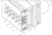
- FIG. 1is a schematic configuration diagram of a laser device according to a first embodiment of the invention.
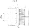
- FIG. 2is a diagram illustrating the laser device according to the first embodiment, in which a heat sink is attached to a housing via coil springs and a heat transfer member;
- FIG. 3is a perspective view of the laser device according to the first embodiment, in which the coil springs are attached to holders;
- FIG. 4is a detailed configuration diagram of the coil spring of the laser device according to the first embodiment of the invention.
- FIG. 5is a perspective view of a laser device according to a second embodiment, in which a leaf spring is adhered to light sources.
- FIG. 1is a schematic configuration diagram of a laser device according to a first embodiment of the invention.
- the laser device as illustrated in FIG. 1includes a plurality of light sources 1 , a plurality of holders 2 , a plurality of collimating lenses 3 , a housing 4 , a condensing lens 5 , and an optical fiber 6 .
- the plurality of light sources 1include, for example, light emitting diodes (LED), laser diodes (LD), or the like, and the light sources 1 are disposed at substantially equal intervals.
- the number of light sources 1is five, but the number of light sources is not limited to five, and the number of light sources 1 may be another number.
- the plurality of collimating lenses 3are provided to correspond to the plurality of light sources 1 , disposed at positions facing the plurality of light sources 1 , and collimate light emitted from the plurality of light sources 1 .
- the plurality of holders 2are provided to correspond to the plurality of collimating lenses 3 , and each holder 2 is formed of a resin or the like. Each holder 2 holds a pair of the light source 1 and the collimating lens 3 and includes an optical axis adjusting mechanism for adjusting an emission position and an emission angle of the collimated light of the collimating lens 3 .
- the housing 4holds the plurality of holders 2 , and is formed of a resin or the like.
- the condensing lens 5is disposed at a position corresponding to the plurality of collimating lenses 3 .
- the condensing lens 5corresponds to a light condensing part of the invention.
- the condensing lens 5condenses the light which is emitted from the collimating lenses 3 whose emission position and emission angle are adjusted, and couples the condensed light to the optical fiber 6 .
- the optical fiber 6transmits the light condensed by the condensing lens 5 .
- FIG. 2illustrates the laser device according to the first embodiment, in which a heat sink 8 is attached to the housing 4 via coil springs 7 and a heat transfer member 7 a.
- the holders 2protrude from a tip end of the housing 4 , and the coil springs 7 are attached to tip ends of the holders 2 .
- the heat transfer member 7 ais attached to the coil springs 7
- the heat sink 8is attached to the heat transfer member 7 a .
- a fan 9is attached to the heat sink 8 .
- FIG. 3is a perspective view of the laser device according to the first embodiment, in which the coil springs 7 are attached to the holders 2 .
- the coil springs 7 and the heat transfer member 7 acorrespond to a heat transfer member of the invention, are disposed between heat exhausting surfaces 1 a of the light sources 1 and a heat absorbing surface 8 a of the heat sink 8 , include an elastic part abutting against the heat exhausting surfaces 1 a of the light sources 1 and the heat absorbing surface 8 a of the heat sink 8 , have heat conductivity, and transfer the heat from the heat exhausting surfaces 1 a of each the sources 1 to the heat absorbing surface 8 a of the heat sink 8 .
- the coil spring 7is formed of any one of copper, a copper alloy, aluminum, an aluminum alloy, and aluminum nitride, and has elasticity. As illustrated in FIG. 4 , both end surfaces of the coil spring 7 are planarized.
- the coil spring 7includes a ring part 71 formed with a through hole 72 , and groove parts 73 are formed in both end parts of the ring part 71 .
- the heat sink 8corresponds to a heat exhausting member of the invention, and exhausts heat generated from the plurality of light sources 1 via the coil springs 7 and the heat transfer member 7 a .
- the fan 9cools the heat sink 8 .
- a water cooling systemmay be used to cool the heat sink 8 .
- the holders 2 after adjustmentare respectively fixed to the housing 4 at different angles.
- the heat exhausting surfaces of the light sources 1 or the heat exhausting surfaces of the holders 2 holding the light sources 1are at different angles due to the optical axis adjustment.
- the coil spring 7 and the heat transfer member 7 awhich have springiness absorb uneven gaps between the heat exhausting surfaces 1 a of the light sources 1 or the heat exhausting surfaces of the holders 2 and the heat absorbing surface 8 a of the heat sink 8 .
- the coil springs 7 and the heat transfer member 7 aa material which has sufficient heat conductivity for heat exhausting and elasticity to be able to absorb a variation of the gaps, such as copper or aluminum, can be used.
- the coil springs 7 and the heat transfer member 7 aare planarized, the heat exhausting surfaces 1 a of the light sources 1 or the heat exhausting surfaces of the holders 2 and the heat absorbing surface 8 a of the heat sink 8 can be in close contact with each other, so that the heat can be easily transferred from the each heat exhausting surface 1 a to the heat absorbing surface 8 a.
- the heat exhausting surfaces 1 a of the light sources 1 and the heat absorbing surface 8 a of the heat sink 8are in closed contact with each other due to the elasticity of the coil springs 7 and heat transfer member 7 a , the uneven gaps between the heat exhausting surfaces 1 a of the light sources 1 and the heat absorbing surface 8 a of the heat sink 8 can be absorbed. Therefore, since the heat can be easily transferred from the heat exhausting surfaces 1 a to the heat absorbing surface 8 a by the coil springs 7 and the heat transfer member 7 a , the heat of the plurality of light sources whose angles are individually adjusted can be efficiently exhausted.
- FIG. 5is a perspective view of a laser device according to a second embodiment, in which a leaf spring is adhered to light sources.
- a leaf spring 10is used as a heat transfer member.
- the laser device of the second embodiment illustrated in FIG. 5is the same as the configuration of the laser device of the first embodiment illustrated in FIG. 2 except the leaf spring 10 .
- the leaf spring 10will only be described.
- the leaf spring 10has a flat plate shape, and is disposed so as to cover the light sources 1 and the holders 2 . Since the leaf spring 10 has the same characteristics and functions as the coil springs 7 have, description thereof will be omitted herein.
- a recess part 10 ais formed at a position facing each light source 1 .
- a circular through hole 10 b for passing two leads for positive and negative electrodes of each light source 1is formed.
- a slit 11is formed between a heat transfer part corresponding to the light source 1 and a heat transfer part corresponding to another light source 1 adjacent to the light source 1 .
- the slits 11serve to separate the light sources 1 .
- the recess parts 10 aare formed to reinforce the leaf spring 10 , and prevent the leaf spring 10 from becoming weak due to the formation of the slits 11 .
- the uneven gaps between the heat exhausting surfaces 1 a of the light sources 1 and the heat absorbing surface 8 a of the heat sink 8can be absorbed.
- the heatcan be easily transferred from the heat exhausting surfaces 1 a to the heat absorbing surface 8 a by the leaf spring 10 and the heat transfer member 7 a , the heat of the plurality of light sources whose angles are individually adjusted can be efficiently exhausted.
- the slit 11is formed between adjacent light sources, and the light sources 1 are separated from each other by the slits 11 , the heat generated from each light source 1 is transferred only to the heat sink 8 , and the heat generated from the light source 1 is not transferred to the adjacent light source 1 via the leaf spring 10 .
- a high heat conductive ceramic materialsuch as aluminum nitride may be used as a heat transfer member.
- the inventionis applicable to laser devices used for analysis, measurement, medical treatment, optical information processing, laser discs, or the like.
Landscapes
- Physics & Mathematics (AREA)
- General Physics & Mathematics (AREA)
- Optics & Photonics (AREA)
- Semiconductor Lasers (AREA)
Abstract
Description
Claims (2)
Priority Applications (1)
| Application Number | Priority Date | Filing Date | Title |
|---|---|---|---|
| US16/111,304US10746944B2 (en) | 2018-08-24 | 2018-08-24 | Laser device |
Applications Claiming Priority (1)
| Application Number | Priority Date | Filing Date | Title |
|---|---|---|---|
| US16/111,304US10746944B2 (en) | 2018-08-24 | 2018-08-24 | Laser device |
Publications (2)
| Publication Number | Publication Date |
|---|---|
| US20200064566A1 US20200064566A1 (en) | 2020-02-27 |
| US10746944B2true US10746944B2 (en) | 2020-08-18 |
Family
ID=69584564
Family Applications (1)
| Application Number | Title | Priority Date | Filing Date |
|---|---|---|---|
| US16/111,304Expired - Fee RelatedUS10746944B2 (en) | 2018-08-24 | 2018-08-24 | Laser device |
Country Status (1)
| Country | Link |
|---|---|
| US (1) | US10746944B2 (en) |
Families Citing this family (1)
| Publication number | Priority date | Publication date | Assignee | Title |
|---|---|---|---|---|
| US11769862B2 (en)* | 2020-03-26 | 2023-09-26 | Nichia Corporation | Light emitting device |
Citations (14)
| Publication number | Priority date | Publication date | Assignee | Title |
|---|---|---|---|---|
| JPH04257248A (en) | 1991-02-12 | 1992-09-11 | Mitsubishi Electric Corp | Hybrid integrated circuit device |
| JP3228098B2 (en) | 1995-11-01 | 2001-11-12 | 横河電機株式会社 | Light source |
| JP2003022542A (en) | 2001-07-10 | 2003-01-24 | Nec Corp | Fixing mechanism of semiconductor laser and optical head device |
| JP2004119706A (en) | 2002-09-26 | 2004-04-15 | Kyocera Corp | heatsink |
| JP2005190520A (en) | 2003-12-24 | 2005-07-14 | Sankyo Seiki Mfg Co Ltd | Optical head device |
| US20060018609A1 (en)* | 2004-07-26 | 2006-01-26 | Fuji Photo Film Co., Ltd. | Laser module with sealed package containing limited optical components |
| JP2008149381A (en) | 2006-12-14 | 2008-07-03 | Ose Fujiko | Method for setting coil spring, method for polishing coil spring using the method, tool for setting coil spring, and apparatus for polishing coil spring using the tool |
| JP2009141136A (en) | 2007-12-06 | 2009-06-25 | Mitsubishi Electric Corp | Heat sink and semiconductor device |
| US20110096543A1 (en)* | 2009-10-28 | 2011-04-28 | Mitoru Yabe | Light source device |
| US20110299700A1 (en)* | 2006-08-18 | 2011-12-08 | Snider Chris R | Lightweight audio system for automotive applications and method |
| JP2012009760A (en) | 2010-06-28 | 2012-01-12 | Casio Comput Co Ltd | Light source device and projector |
| JP2013138086A (en) | 2011-12-28 | 2013-07-11 | Nichia Chem Ind Ltd | Light source device |
| US20150087180A1 (en)* | 2013-09-25 | 2015-03-26 | Tyco Electronics (Shanghai) Co. Ltd. | Connector for plug, connector and heat conduction apparatus |
| US20170150645A1 (en)* | 2015-11-20 | 2017-05-25 | Huawei Technologies Co., Ltd. | Heat dissipation assembly and communications device |
- 2018
- 2018-08-24USUS16/111,304patent/US10746944B2/ennot_activeExpired - Fee Related
Patent Citations (14)
| Publication number | Priority date | Publication date | Assignee | Title |
|---|---|---|---|---|
| JPH04257248A (en) | 1991-02-12 | 1992-09-11 | Mitsubishi Electric Corp | Hybrid integrated circuit device |
| JP3228098B2 (en) | 1995-11-01 | 2001-11-12 | 横河電機株式会社 | Light source |
| JP2003022542A (en) | 2001-07-10 | 2003-01-24 | Nec Corp | Fixing mechanism of semiconductor laser and optical head device |
| JP2004119706A (en) | 2002-09-26 | 2004-04-15 | Kyocera Corp | heatsink |
| JP2005190520A (en) | 2003-12-24 | 2005-07-14 | Sankyo Seiki Mfg Co Ltd | Optical head device |
| US20060018609A1 (en)* | 2004-07-26 | 2006-01-26 | Fuji Photo Film Co., Ltd. | Laser module with sealed package containing limited optical components |
| US20110299700A1 (en)* | 2006-08-18 | 2011-12-08 | Snider Chris R | Lightweight audio system for automotive applications and method |
| JP2008149381A (en) | 2006-12-14 | 2008-07-03 | Ose Fujiko | Method for setting coil spring, method for polishing coil spring using the method, tool for setting coil spring, and apparatus for polishing coil spring using the tool |
| JP2009141136A (en) | 2007-12-06 | 2009-06-25 | Mitsubishi Electric Corp | Heat sink and semiconductor device |
| US20110096543A1 (en)* | 2009-10-28 | 2011-04-28 | Mitoru Yabe | Light source device |
| JP2012009760A (en) | 2010-06-28 | 2012-01-12 | Casio Comput Co Ltd | Light source device and projector |
| JP2013138086A (en) | 2011-12-28 | 2013-07-11 | Nichia Chem Ind Ltd | Light source device |
| US20150087180A1 (en)* | 2013-09-25 | 2015-03-26 | Tyco Electronics (Shanghai) Co. Ltd. | Connector for plug, connector and heat conduction apparatus |
| US20170150645A1 (en)* | 2015-11-20 | 2017-05-25 | Huawei Technologies Co., Ltd. | Heat dissipation assembly and communications device |
Non-Patent Citations (1)
| Title |
|---|
| Office Action dated Mar. 26, 2019, in corresponding Japanese Application No. 2016-035765; 9 pages. |
Also Published As
| Publication number | Publication date |
|---|---|
| US20200064566A1 (en) | 2020-02-27 |
Similar Documents
| Publication | Publication Date | Title |
|---|---|---|
| CA2716066C (en) | Light source device | |
| CN102053319B (en) | Light source device | |
| JP2645862B2 (en) | Semiconductor light emitting device and its applied products | |
| KR100835619B1 (en) | Modular assembly utilizing laser diode subassemblies with winged mounting blocks | |
| JP6272067B2 (en) | Laser light source module and laser light source device | |
| US11619365B2 (en) | Light source unit, illumination device, processing equipment, and deflection element | |
| CN115039302A (en) | Semiconductor laser device | |
| US10746944B2 (en) | Laser device | |
| US9548586B2 (en) | Energy integrating device for split semiconductor laser diodes | |
| JP6351090B2 (en) | Light source unit, illumination optical system using light source unit | |
| JP6521098B2 (en) | Combined laser light source | |
| JP2011216583A (en) | Semiconductor laser device and optical pickup device using the same | |
| US9570666B2 (en) | Silicon-based cooling package for light-emitting devices | |
| JP6613957B2 (en) | Laser equipment | |
| JP5985899B2 (en) | Semiconductor laser device | |
| JP7558955B2 (en) | Laser Equipment | |
| US11588296B2 (en) | Package, light-emitting device, and laser device | |
| JP6536842B2 (en) | Laser device | |
| US10539280B2 (en) | Light-source device | |
| JP2019204939A (en) | Laser apparatus | |
| JP2006049788A (en) | Laser light source device |
Legal Events
| Date | Code | Title | Description |
|---|---|---|---|
| AS | Assignment | Owner name:SHIMADZU CORPORATION, JAPAN Free format text:ASSIGNMENT OF ASSIGNORS INTEREST;ASSIGNORS:ISHIGAKI, NAOYA;TOJO, KOJI;REEL/FRAME:046691/0862 Effective date:20180712 | |
| FEPP | Fee payment procedure | Free format text:ENTITY STATUS SET TO UNDISCOUNTED (ORIGINAL EVENT CODE: BIG.); ENTITY STATUS OF PATENT OWNER: LARGE ENTITY | |
| STPP | Information on status: patent application and granting procedure in general | Free format text:FINAL REJECTION MAILED | |
| STPP | Information on status: patent application and granting procedure in general | Free format text:DOCKETED NEW CASE - READY FOR EXAMINATION | |
| STPP | Information on status: patent application and granting procedure in general | Free format text:NOTICE OF ALLOWANCE MAILED -- APPLICATION RECEIVED IN OFFICE OF PUBLICATIONS | |
| ZAAA | Notice of allowance and fees due | Free format text:ORIGINAL CODE: NOA | |
| ZAAB | Notice of allowance mailed | Free format text:ORIGINAL CODE: MN/=. | |
| STCF | Information on status: patent grant | Free format text:PATENTED CASE | |
| FEPP | Fee payment procedure | Free format text:MAINTENANCE FEE REMINDER MAILED (ORIGINAL EVENT CODE: REM.); ENTITY STATUS OF PATENT OWNER: LARGE ENTITY | |
| LAPS | Lapse for failure to pay maintenance fees | Free format text:PATENT EXPIRED FOR FAILURE TO PAY MAINTENANCE FEES (ORIGINAL EVENT CODE: EXP.); ENTITY STATUS OF PATENT OWNER: LARGE ENTITY | |
| STCH | Information on status: patent discontinuation | Free format text:PATENT EXPIRED DUE TO NONPAYMENT OF MAINTENANCE FEES UNDER 37 CFR 1.362 | |
| FP | Lapsed due to failure to pay maintenance fee | Effective date:20240818 |