US10745220B2 - Vehicle Restraint System - Google Patents
Vehicle Restraint SystemDownload PDFInfo
- Publication number
- US10745220B2 US10745220B2US16/022,236US201816022236AUS10745220B2US 10745220 B2US10745220 B2US 10745220B2US 201816022236 AUS201816022236 AUS 201816022236AUS 10745220 B2US10745220 B2US 10745220B2
- Authority
- US
- United States
- Prior art keywords
- hook
- insert
- loading dock
- restraint
- vehicle
- Prior art date
- Legal status (The legal status is an assumption and is not a legal conclusion. Google has not performed a legal analysis and makes no representation as to the accuracy of the status listed.)
- Active, expires
Links
Images


Classifications
- B—PERFORMING OPERATIONS; TRANSPORTING
- B65—CONVEYING; PACKING; STORING; HANDLING THIN OR FILAMENTARY MATERIAL
- B65G—TRANSPORT OR STORAGE DEVICES, e.g. CONVEYORS FOR LOADING OR TIPPING, SHOP CONVEYOR SYSTEMS OR PNEUMATIC TUBE CONVEYORS
- B65G69/00—Auxiliary measures taken, or devices used, in connection with loading or unloading
- B65G69/003—Restraining movement of a vehicle at a loading station using means not being part of the vehicle
Definitions
- the present inventionrelates to dock restraint systems used to secure vehicles, such as semitrailers, proximate a loading dock. More specifically, the present invention relates to a status indicator and hook control system and hook assembly used with dock restraint systems.
- Vehicle restraint systemsare commonly used to secure a vehicle, such as a semitrailer relative to a loading dock. When engaged, such restraint systems prevent translation of the vehicle relative to the loading dock and/or a dock plate.
- a dock plateis a ramp or the like that provides a transition from dock areas to the load space associated with the vehicle.
- the vehicleis secured such that the bed of the vehicle's storage area can be conveniently accessed by personnel and/or equipment associated with loading and unloading operations while the position of the vehicle is maintained relative to the dock or dock area.
- the vehicle restraint device or systemincludes a carriage that is adjustably mounted to a mounting plate connected to a wall adjacent to the dock.
- the carriageis commonly configured to slideably cooperate with the underside of an underride or rear impact guard that is associated with the frame of the load vehicle.
- the restraining memberis pivotably supported by the carriage such that the restraint can be selectively engaged and disengaged from interaction with the rear impact guard.
- User interaction with the restraint assemblyis commonly effectuated via a control panel.
- the control panelis commonly configured to receive input signals from loading personnel to effectuate a desired “secure” or “release” operation of the associated restraint relative to an underlying vehicle.
- the control systemis further commonly configured to provide a restraint status indicator to the vehicle operator as well as surrounding personal to provide an indication that the restraint has achieved a desired orientation relative to the underlying vehicle to achieve the desired “secure” or “released”, or “engaged or “disengaged” status of the restraint relative to the underlying vehicle.
- Translation of the vehicle during loading and unloading operationscan result in “jamming” of the restraining member and/or undesired interference of the restraining member with the vehicle guard.
- This undesired interference or “jamming” of the restraint system with the underlying vehiclecan result in the inability to engage or disengage the restraining member from interaction with the vehicle guard when desired.
- the inability to achieve the desired engagement or disengagement of the restraining member or dock hook from the vehiclemust be resolved by physically moving the vehicle relative to the carriage and/or restraint to effectuate the desired engagement and/or disengagement of the restraining member from the vehicle or trailer associated with the loading dock.
- Such undesired interactionproves problematic when trailers are left in a loading dock without an associated power vehicle such as a tug, tractor, or semi-tractor or operators or drivers are unavailable to operate the vehicle being loaded.
- the control system associated with operation of the underlying restraint systemincludes a plurality of discrete indicators that designate the respective status of the underlying restraint system.
- One common methodologyincludes providing a plurality of light elements, commonly of different colors and/or positioned at different locations, that designate the discrete condition of the underlying restraint system as being one or more of engaged and secure, engaged but non-secure, disengaged, and/or disengaged and fully retracted.
- the various locations and/or different color indications or designations associated with the various discrete conditions associated with operation of the underlying restraint systemcan leave personnel and/or vehicle operators unclear or confused as to a current condition associated with a discrete vehicle restraint system. Such confusion or misinterpretation can be exacerbated by the various different presentation methodologies associated with assessing the status of the discrete vehicle restraint systems when discrete facilities are equipped with restraint status, indicia, or indicator systems.
- the present inventiondiscloses a vehicle securing system that overcomes one or more of the drawbacks disclosed above.
- a vehicle restraint assemblythat includes a control system that provides a reduced number of independently operable restraint status indicators as compared to other vehicle restraint systems.
- the restraint control systemincludes a single illumination device whose illumination characteristic or intensity is manipulated so as to provide an indication as to a current condition associated with operation of the underlying restraint.
- FIG. 1illustrate various views of restraint systems and alternate embodiments of hook assemblies associated with a vehicle dock restraints or restraint systems presently contemplated for carrying out the invention.
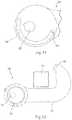
- FIG. 1is a perspective view of a vehicle restraint hook or restraint according to one embodiment of the invention
- FIG. 2is a plan view of the restraint shown in FIG. 1 ;
- FIG. 3is a perspective view of an insert that is constructed to cooperate with the restraint shown in FIG. 1 ;
- FIG. 4is a side elevation view of the insert shown in FIG. 3 ;
- FIG. 5is a lateral side elevation view of the insert shown in FIG. 3 ;
- FIG. 6is a perspective side view of a cover constructed to cooperate with the restraint and the insert shown in FIGS. 1 and 3 ;
- FIG. 7is a laterally outboard side elevation view of the cover shown in FIG. 6 ;
- FIG. 8is a perspective view of the restraint shown in FIG. 1 with the insert shown in FIG. 3 and the cover shown in FIG. 6 associated therewith;
- FIG. 9is an elevation section view of a portion of the restraint and insert taken along line 9 - 9 shown in FIG. 8 ;
- FIG. 10is a side elevation view of the restraint, insert, and cover shown in FIG. 8 with a vehicle frame member or underride guard associated therewith and the restraint oriented in an engaged orientation relative to the restraint;
- FIG. 11is a view similar to FIG. 9 with the insert in a second orientation relative to the restraint;
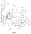
- FIG. 12is a view similar to FIG. 10 with the restraint oriented in a second or intermediate orientation relative to the underride guard of a vehicle guard during engagement and disengagement translation of the restraint relative thereto;
- FIG. 13is a side elevation view of the restraint and insert assembly oriented in an engaged orientation relative to an underride guard associated therewith;
- FIG. 14is an elevation detail cross section view of the restraint, insert, and cover assembly taken along line 14 - 14 shown in FIG. 13 ;
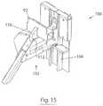
- FIG. 15is a perspective view of the restraint shown in FIGS. 10-13 supported by a carriage associated with a vehicle restraint assembly according to the present invention with a vehicle underride guard associated therewith;
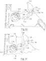
- FIG. 16is a view similar to FIG. 15 with a side panel of the carriage exploded from the vehicle restraint assembly;
- FIG. 17is a side elevation view of the assembly shown in FIG. 16 ;
- FIGS. 18, 19, 20, 21, 22, 23, 24 and 25are various side elevation views of a portion of the vehicle restraint assembly shown in FIG. 16 with an opposite side panel of the carriage removed therefrom and the restraint moving sequentially through a retracted or disengaged orientation relative to the carriage toward an engaged orientation relative to the carriage and an underride guard;
- FIG. 26is a view similar to FIGS. 18-25 and shows the restraint translated away from the engaged position relative to the carriage and translation of a latch and a catch relative to one another to facilitate disengagement of the vehicle underride guard from the vehicle restraint system;
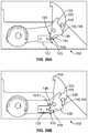
- FIGS. 27-28are elevational views of the latch shown in FIGS. 18-26 and show the gravitational translation of the latch;
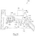
- FIG. 29is a view similar to FIGS. 18-26 and shows the latch and catch operationally dissociated to facilitate translation of the vehicle restraint toward a retracted or stowed position relative to the carriage such that the restraint does not interfere with translation of the vehicle in a disengage direction relative to the vehicle restraint system;
- FIGS. 29A and 29Bshow a view similar to FIG. 29 of a latch and catch construction according to an alternate embodiment of the invention
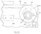
- FIGS. 30 and 31are an elevation and perspective view, respectively, of a portion of a restraint and a carriage according to another embodiment of the invention and constructed to prevent over rotation of the restraint relative to the carriage;
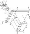
- FIG. 32is a perspective view of a vehicle restraint system having a non-axial drive arrangement in accordance with another embodiment of the invention.
- FIG. 33is a side elevation view of vehicle restraint system shown in FIG. 32 ;
- FIG. 33Ais a view similar to FIG. 32 of a portion of a vehicle restraint system having a non-axial manually operable drive arrangement according to another embodiment of the invention.
- FIG. 34is a perspective view of a control system associated with operation of the vehicle restraint systems shown in the preceding figures;
- FIG. 35is an exploded perspective view of the control system shown in FIG. 34 ;
- FIG. 36is an exploded perspective view of an additional restraint status indicator system useable with the control system shown in FIG. 35 ;
- FIG. 37is a schematic representation of a first embodiment of the control system shown in FIG. 34 ;
- FIGS. 38A and 38Bare portions of a schematic representation of the control system shown in FIG. 34 according to an alternate embodiment of the invention.
- FIGS. 1 and 2show an exemplary restraint or hook 32 that forms a portion of a vehicle restraining or vehicle restraint system 100 ( FIG. 15 ) whose operation is configured to be manipulated by the control system as disclosed further below according to a first embodiment of the present invention.
- a hook assembly 30includes hook 32 that is constructed to cooperate with a cam or an insert 60 and a cover 80 such that hook assembly 30 can be secured to a carriage associated with vehicle restraint system 100 such that hook 32 is movable between an engaged position and a retracted position.
- hook assembly 30When in an “engaged” position, hook assembly 30 interacts with a vehicle frame member, such as an underride guard or the like, such that the vehicle is restrained relative to the restraint system 100 , and adjacent structure such as a loading dock area, dock plate, or the like, to facilitate secure interaction with the vehicle being loaded and/or unloaded.
- a vehicle frame membersuch as an underride guard or the like
- adjacent structuresuch as a loading dock area, dock plate, or the like
- hook 32includes a generally circular base portion 34 , a body 39 , and a tooth 50 disposed at a distal end thereof generally opposite the generally circular base portion 34 .
- the generally circular base portion 34comprises an outer rim 36 with an opening 38 located therein. As disclosed further below, opening 38 is constructed to cooperate with an insert that is constructed to accommodate rotational securing of hook 32 relative to a carriage associated with the vehicle restraint system 100 .
- the circular base portion 34may include a dowel pin opening 48 that extends through outer rim 36 .
- Body 39 of hook 32extends from the outer rim 36 initially laterally into a shank 40 before turning at a generally 90 degree angle into a crown 42 .
- Shank 40 of body 39has an upper surface 44 and crown 42 has a side surface 46 . Both upper surface 44 of shank 40 and side surface 46 of crown 42 are configured to preferably contact a portion of a vehicle or underride guard 92 as described below. As disclosed further below, in some vehicle configuration, a distal face 93 of tooth 50 may contact the structure of an underlying vehicle and effectuate the securing operation associated with the “engaged” orientation of hook 32 . As shown in FIGS. 1 and 2 , tooth 50 extends generally perpendicular to crown 42 of hook 32 at the edge of the crown 42 that is generally opposite the bend.
- tooth 50defines a lip 95 that engages a top-facing portion of the vehicle or vehicle guard 92 when the hook assembly 30 is in use.
- face 93 of tooth 50may engage the vehicle facing side of such frame structures and the cooperation of hook 32 with the underlying carriage provides a secure interaction between hook 32 and the vehicle underride guard structure as disclosed further below with respect to FIGS. 24 and 25 .
- an insert 60is configured to cooperate with opening 38 defined by body 39 of hook 32 .
- Insert 60includes a base 62 that is generally flat and a shaft 64 that extends in a crossing direction away from base 62 .
- Base 62 and shaft 64 of insert 60are generally concentric with respect to one another with shaft 64 having a smaller diameter than base 62 .
- Such a constructiondefines a shoulder 66 that is formed by the outward radial extension of base 62 beyond a radially oriented exterior surface of shaft 64 .
- a diameter of shaft 64is slightly smaller than a diameter of opening 38 associated with outer rim 36 of hook 32 such that shaft 64 may be inserted into opening 38 .
- a height of the shaft 64is preferably substantially similar to the width of opening 38 .
- the diameter of shaft 64is dimensioned within machine operation and assembly tolerances associated with the axially slideable interaction between shaft 64 and hook 32 during assembly of hook assembly 30 .
- insert 60has a number of openings.
- a series of blind holes or fastener openings 68are formed on an end face of shaft 64 and are configured to receive screws, bolts, pins, or other attachment devices associated with securing cover 80 to insert 60 such that outer rim 36 of hook 32 is captured between shoulder 66 associated with base 62 and cover 80 when hook assembly 30 is assembled.
- Insert 60preferably includes an insert pivot opening or pivot hole 70 that extends through the height of insert 60 including base 62 and shaft 64 .
- Insert pivot hole 70is generally circular with a key, keyhole 71 , or other means to prevent relative rotation between a mating shaft and pivot hole 70 .
- insert pivot hole 70is configured to receive a driving member or drive shaft 143 ( FIG. 16 ) associated with facilitating the desired rotation of insert 60 , cover 80 , and hook 32 during rotation of the drive shaft. As shown in FIG. 5 , insert pivot hole 70 is offset from the center of the insert 60 . That is, insert pivot hole 70 is eccentric relative to the center axis of insert 60 and is thereby eccentrically oriented relative to hook 32 . As disclosed further below, the eccentric orientation of the drive member relative to hook 32 provides lateral translation of hook 32 relative to an underlying carriage during selected portions of the range of travel associated with operation of hook 32 .
- Base 62 of insert 60additionally has a groove or slot 72 that is formed in shoulder 66 .
- slot 72extends at least approximately halfway around a circumference of insert 60 , more preferably greater than 180 degrees, and more preferably approximately 210 degrees of the circumference of insert 60 .
- the rotational association between insert 60 and hook 32allows relative rotation therebetween to achieve an over-center orientation between the axis of rotation associated with pivot hole 70 associated with insert 60 and the axis of rotation associated with hook 32 such that hook 32 can resist rotation of hook 32 relative to insert 60 in response to lateral forces imparted to crown 42 of hook 32 when hook 32 is engaged with a vehicle during vehicle loading and unloading operations.
- Slot 72is preferably located directly adjacent outer rim 36 of hook 32 when shaft 64 of insert 60 is associated with opening 38 of hook 32 .
- a groove 74is formed in shaft 64 and extends in a generally circumferential direction about a radially exterior surface of shaft 64 .
- Groove 74is constructed to accommodate the communication of lubrication or dispersal of grease or the like along the interface between shaft 64 of insert 60 and inner wall 37 of outer rim 36 of hook 32 . As described below, such a construction allows insert 60 to rotate relative to the outer rim 36 of hook 32 with reduced frictional interaction, damage, degradation, or wear between the movable relative surfaces of insert 60 and hook 32 .
- FIGS. 6-7show a cover 80 that is constructed to cooperate with hook 32 and insert 60 at an opposite lateral side of hook assembly 30 .
- the opposite lateral sides of hook assembly 30are those sides that face in generally opposite lateral directions and are oriented normal to the axis of rotation defined by the curvilinear surfaces of shaft 64 and insert pivot hole 70 .
- Cover 80has a number of features that generally mirror or are complimentary to the features of insert 60 .
- cover 80has a cover pivot hole 82 that extends through cover 80 .
- Cover pivot hole 82is offset or eccentric from the center of the cover 80 , is generally circular, and also includes a keyway, keyhole or other means to prevent the mating or drive shaft from rotating within cover pivot hole 83 .
- Cover 80includes a series of fastener holes 84 that extend through cover 80 and correspond to holes or openings 68 associated with insert 60 .
- a laterally inboard facing side or underside 86 of cover 80features a groove or slot 88 that extends approximately at least halfway around a circumference the cover 80 , approximately greater than 180 degrees, and more preferably approximately 210 degrees of the circumference of cover 80 .
- shaft 64 of insert 60is inserted into opening 38 of hook 32 .
- Shaft 64is inserted into hook 32 until shoulder 66 of base 62 is adjacent to, abuts, or impinges upon outer rim 36 of hook 32 .
- insert pivot hole 70is then aligned with cover pivot hole 82 .
- One or more fasteners, such as screws, bolts, or other attachment devicesare then inserted into the fastener holes 84 of cover 80 and into operative engagement with fastener openings 68 associated with insert 60 .
- outer rim 36 of hook 32is located or captured between insert 60 and cover 80 , as shown in FIG. 8 .
- hook assembly 30can be slideably associated with a drive or pivot shaft ( FIG. 18 ) associated with the vehicle restraint system as the drive shaft extends through the insert pivot hole 70 and the cover pivot hole 82 and can be keyed relative thereto.
- rotational operation of the drive shafteffectuates selective translation of the hook assembly 30 relative to the underlying carriage assembly and facilitates selective interaction of hook 32 with a vehicle associated with vehicle restraint system 100 .
- the eccentric association of hook 32 with pivot hole 70 associated with insert 60allows hook assembly 30 to translate in an eccentric rotational manner about a pivot axis defined by the pivot shaft.
- insert 60 and cover 80can additionally eccentrically rotate relative to outer rim 36 of hook 32 .
- the rotational movement of insert 60 and cover 80 relative to hook 32can be limited as disclosed further below.
- hook assembly 30preferably includes a dowel pin 90 that passes through dowel pin opening 48 of hook 32 .
- the generally opposite longitudinal ends of pin 90slideably cooperate with slot 72 associated with laterally inboard facing side of insert 60 and slot 88 associated the laterally inboard facing side of cover 80 . That is, dowel pin 90 has a longitudinal length that is slightly longer than a lateral width of outer rim 36 of body 39 of hook 32 . Consequently, dowel pin 90 protrudes into both insert slot 72 and the cover slot 88 .
- Such cooperationallows insert 60 and cover 80 to rotate relative to circular base portion 34 along the length of the slots 72 , 88 . Put another way, the cooperation of pin 90 with slots 72 , 88 limits the degree of relative rotation between hook 32 and insert 60 .
- the function associated with the pincould be provided in other methodologies.
- the outer radial surface of base portion 34 of hook 32could be provided with a contour such as a lobe or the like that is constructed to cooperate with a projection or pin that extends in an inboard lateral direction relative to the insert 60 and/or cover 80 to provide the desired cooperation between insert 60 , cover 80 , and hook 32 that facilitates the selective rotational association between insert 60 and cover 80 and hook 32 .
- FIG. 9illustrates a cross section of the hook assembly 30 when the dowel pin 90 is located at a first end of insert slot 72 and cover slot 88 .
- Insert 60 and cover 80are rotatable relative to hook 32 as pin 90 travels between the first end of the slots 72 , 88 and the second end of the slots 72 , 88 as shown in FIG. 11 .
- the configuration of the slots 72 , 78limits movement of insert 60 and cover 80 around the circular base portion 34 of hook 32 to those positions shown in FIGS. 9 and 11 and any positions therebetween.
- hook 32when in use, hook 32 is used to generally engage a portion of the vehicle or vehicle frame member, such as a vehicle guard or an underride guard 92 .
- a vehicle guard or an underride guard 92Such underride guards are normally generally horizontally oriented and disposed near the rear portion of a vehicle.
- the hook 32can be moved relative to the underride guard 92 of a truck via operation of the vehicle restraint device that effectuates rotation of the shaft associated with pivot hole 70 .
- the underride guard 92may slide in a horizontal direction along the upper surface 44 of the shank 40 and in a limited vertical direction along the side surface 46 associated with the crown 42 .
- tooth 50 associated with hook 32when engaged with a generally open tubular structured underride guard, tooth 50 associated with hook 32 cooperates with an upward facing surface of underride guard 92 to secure the vehicle relative to the loading dock, as can best be seen in FIG. 10 . If the tooth 50 is initially loosely engaged with the guard 92 , continued rotation of the hook in a generally upward direction toward a dock area results in vehicle restraint device more tightly engaging the underride guard 92 .
- FIG. 10shows the hook assembly 30 in the same relative orientation as FIG. 9 when the hook 32 is engaged with the underride guard 92 .
- the hook 32cannot be rotated downwardly away from the vehicle due to the inferring interaction of guard 92 with tooth 50 .
- hook assembly 30moves in a generally forward lateral direction relative to guard 92 .
- FIG. 12which shows the hook assembly oriented at a generally forward orientation relative to vehicle guard 92 when insert 60 , cover 80 , and body 39 are in the orientations shown in FIG. 11 as evidenced by the forwarded oriented position of the eccentric lobe defined by insert 60 with respect to the axis of rotation associated with keyed drive shaft or pivot hole 70 .
- tooth 50achieves an orientation wherein tooth 50 clears the underride guard 92 , and hook assembly 30 can be rotated downwardly away from the vehicle in response to continued clockwise rotation of the drive shaft associated with pivot hole 70 .
- Such continued rotationallows tooth 50 and crown side surface 46 to rotate to an orientation out of interference with guard 92 such that a vehicle associated with guard 92 can be removed or disengaged from the vehicle restraint system associated with hook 32 .
- hook assembly 30can be provided with a ball 54 and detent 52 arrangement configured to retain hook 32 in an extended position until it contacts the underride guard 92 .
- the force associated with the initial contactunseats ball 54 from a ball detent 52 defined by insert 60 such that insert 60 can continue to rotate and bias the underride guard 92 toward the dock.
- the ball 54 and opening or detent 52are shown in more detail in FIG. 14 .
- the insert 60 and cover 80can again be rotated from the position shown in FIG. 9 to the position shown in FIG. 11 so that the hook tooth 50 clears the underride guard 92 , and the hook 32 can be rotated in a generally downward direction so that the vehicle can be disengaged from the retaining system.
- FIGS. 15-29show various views of a vehicle restraint system 100 according to another embodiment of the present invention.
- Vehicle restraint system 100includes a carriage or carriage assembly 102 that slideably cooperates with a rail 104 that is configured to be secured to a generally vertical support structure, such as a wall, oriented generally below a discrete loading dock area.
- Vehicle restraint system 100includes a restraint or hook assembly 106 that is movable or rotatable relative to carriage assembly 102 in a manner similar to that described above with respect to hook assembly 30 .
- hook assembly 106is secured to carriage assembly 102 via an eccentric pivot assembly or eccentric pivot 108 similar to that described above with respect the hook assembly 30 to include an insert and a cover so that hook portion 110 of hook assembly 106 is movable between a disengaged or retracted position and an extended or engaged position as shown in FIGS. 15 and 16 to allow selective securing or release of an underride guard 92 relative to vehicle restraint system 100 .
- hook assembly 30 described aboveis constructed to cooperate with carriage assembly 102 so as to be operable with respect to engagement and disengagement with a vehicle frame member in the manner described above and as described below.
- hook portion 110 of hook assembly 106when retracted, hook portion 110 of hook assembly 106 is disposed generally below upper surface 112 of carriage assembly 102 such that the hook assembly 106 does not otherwise interfere with the longitudinal translation of a vehicle underride guard relative to the vehicle restraint system 100 .
- hook portion 110When engaged or oriented in an extended position relative to carriage assembly 102 , hook portion 110 extends generally above upper surface 112 of carriage assembly 102 so as to selectively interfere with outward longitudinal translation of underride guard 92 relative to restraint system 100 in a manner similar to that described above with respect to hook assembly 30 .
- vehicle restraint system 100includes a hook position securing system that mitigates undesired translation of the hook assembly relative to the carriage assembly during certain situations associated with engagement of the hook assembly 106 with a respective underride guard 92 .
- Vehicle restraint system 100includes a first latch 116 and a second latch 118 that are each rotationally supported along generally opposite lateral sides of a hook 120 of hook assembly 106 .
- each latch 116 , 118is oriented and constructed to cooperate with a respective stop 122 associated with the respective side panel 124 , 126 of carriage assembly 102 .
- Each latch 116 , 118is also constructed to selectively cooperate with a respective catch 128 that extends in an outward lateral direction relative to hook 120 .
- respective latches 116 , 118 ; stops 122 ; and catches 128are constructed and oriented to cooperate with the eccentric motion of hook 120 relative to carriage assembly 102 to achieve the desired selectively securable interaction of hook 120 with underride guard 92 and to selectively maintain hook 120 in the extended orientation relative to carriage assembly 102 when desired.
- rear portion 148 of respective latches 116 , 118includes a cutout 149 configured to cooperate with a recess 151 formed in a forward facing face 153 associated with respective stops 122 .
- an indicationcan be provided to operators and adjacent personal indicating the desired restraint of the vehicle when the respective hooks are positively engaged with the underlying stop.
- cutouts 149 and recess 151cooperate with one another in a manner wherein forward or upward rotation of hook 120 is required to effectuate the desired translation of the respective latches 116 , 118 relative to the respective stops 122 to effectuate disengagement therebetween to allow continued downward rotation of hook 120 relative to carriage assembly 102 .
- hook 120when retracted, hook 120 is disposed generally between panels 124 , 126 of carriage assembly 102 .
- Latches 116 , 118are preferably freely rotatable relative to pivot 130 such that a projection 132 associated with each latch 116 , 118 rests upon a respective catch 128 supported by hook 120 .
- Each latch 116 , 118further includes an optional lobe 136 that is also constructed to cooperate with catch 128 and oriented to prevent over rotation of the respective latches 116 , 118 relative to hook 120 .
- Lobes 136also manipulate the position of the center of gravity associated with latches 116 , 118 such that the center of gravity maintains a desired offset or over center orientation of the center of gravity relative to the axis associated with pivot 130 for the reasons described further below with respect to FIGS. 27-28 .
- drive shall 143can be provided in various operational modalities such as by electrical means (i.e. a motor or the like), hydraulic means (i.e. a hydraulic pump, motor, or the like), a pressurized flow means (i.e. an air pump, motor or the like), or combinations of one or more such operational modalities to achieve the desired bidirectional rotational operation of drive shaft 143 .
- electrical meansi.e. a motor or the like
- hydraulic meansi.e. a hydraulic pump, motor, or the like
- a pressurized flow meansi.e. an air pump, motor or the like
- latches 116 , 118rotate in an opposite direction relative to the direction associated with the latches bypassing of stops 122 , as indicated by arrow 152 , about respective pivots 130 such that projections 132 come to rest upon catches 128 .
- underride guard 92can be effectively retained between hook 120 and rail 104 along upper surface 112 of carriage assembly 102 when hook 120 is extended even though latch 116 , 118 may be offset from stop 122 .
- eccentric pivot 108achieves and maintains an over-center orientation of the cam shaft associated with the insert and cover associated with eccentric pivot 108 to resist translation of the hook relative to the carriage due to loading of the hook by the underride guard.
- the eccentric pivot assemblymaintains an orientation wherein the cam shaft is approximately 30 degrees past center to resist translation of the hook due to loading associated with the underride guard.
- latches 116 , 118In some situations, such as if a plate, brace, or gusset 160 interferes with a secure cooperation of tooth 156 of hook 120 with upper surface 158 of underride guard 92 , rear portions 148 of latches 116 , 118 impinge upon stops 122 as projections 132 impinge upon catches 128 . It should be appreciated from the orientation of latches 116 , 118 shown in FIG.
- eccentric pivot assembly 108operates to facilitate initial generally lateral translation, indicated by arrow 168 , of hook 120 relative to carriage assembly 102 as described above.
- latches 116 , 118translate in a generally forward direction relative to stops 122 such that rear portion 148 of latches 116 , 118 can pass beyond the upward forward portion 150 of respective stops 122 .
- Such translation of hook 120allows latches 116 , 118 to bypass stops 122 such that hook 120 can be translated in a generally forward and downward direction, indicated by arrow 170 , during continued operation or rotation of the eccentric pivot 108 associated with hook 120 .
- the continued forward and downward translation of hook 120 relative to carriage assembly 102allows underride guard 92 to be removed from the vehicle restraint system 100 as hook 120 achieves a fully retracted orientation relative to carriage assembly 102 .
- latches 116 , 118are constructed such that a center of gravity 176 associated with each latch 116 , 118 is disposed between the axis associated with pivot 130 and projection 132 .
- the center of gravity of latches 116 , 118is maintained at locations forward of the axis associated with pivot 130 throughout the range of motion of hook 120 relative to carriage assembly 102 . That is, whether latch 116 , 118 is oriented to be engaged with a respective catch 128 or in an orientation wherein the respective latch 116 , 118 is bypassing the respective stop 122 during raising of the cantilevered distal end of hook 120 as shown in FIG.
- center of gravity 176is maintained generally forward or at an offset or over-center orientation relative to the axis associated with pivot 130 such that latches 116 , 118 are gravitationally biased to rotate in a generally clockwise direction relative to the orientation shown in FIGS. 27-28 .
- a biasing devicesuch as a spring or the like, could also be provided to maintain latches 116 , 118 in the desired position and/or orientation to achieve the selective interference with stops 122 in the manner described above.
- latches 116 , 118 , stops 122 , and catches 128could be provided in other configurations.
- stops 122could be secured to hook 120 rather than carriage assembly 102 and configured to bypass a latch secured to the carriage assembly 102 .
- two latch, stop, and catch associationsare shown, it is also further appreciated that fewer such associations can be provided.
- one or more of the structures associated with the operation of hook, latch, catch, and/or stopcould be external thereto. Such modifications are considered encompassed by the appending claims.
- FIGS. 30 and 31show views of an optional stop assembly 200 that can be included in either of hook assembly 30 and/or hook assembly 106 of restraint system 100 and is constructed to prevent rotation of an eccentrically mounted restraint, hook, or hook assembly 202 relative to a carriage 204 beyond a desired threshold.
- hook assembly 202includes a base portion 205 that is configured to cooperate with an insert 206 to effectuate eccentric motion of hook assembly 202 relative to a carriage 204 in response to rotation of a drive shaft 210 as disclosed above.
- hook assembly 202includes a stop or lobe 212 that extends in a generally outward radial direction from base portion 205 of hook assembly 202 .
- Lobe 212is circumferentially oriented relative to base portion 205 of hook assembly 202 to selectively impinge upon a projection or a post (not shown) that traverses the cavity defined by carriage 204 .
- the position of the postis represented in FIGS. 30 and 31 as a hole or opening 214 formed in respective side panels associated with carriage 204 .
- each side panel associated with carriage 204includes an opening 214 that is aligned with a corresponding opening formed in the opposite side panel such that that a bolt or a pin can be associated with each of the respective openings 214 . It should be appreciated from the orientation shown in FIGS. 30 and 31 that the post would extend in a direction generally normal to the view shown in FIGS. 30 and 31 .
- opening 214is further from surface 216 of hook assembly 202 and in response to the eccentric motion of hook assembly 202 relative to carriage 204 during clockwise rotation of drive shaft 210 , with respect to the orientation shown in FIGS. 30 and 31 , surface 216 gradually approaches opening 214 as lobe 212 nears interference with the post associated with opening 214 .
- Such a constructionprovides a robust impediment for preventing rotation of hook assembly 202 relative to carriage 204 beyond a desired rotational position associated with engagement of hook assembly 202 with a respective vehicle structure.
- Lobe 212 and the post associated with opening 214improve the service life associated with the cyclic operation of a vehicle restraining system having such a construction.
- drive shaft 143can be effectuated according to a number of methodologies including for example electric drive systems such as motors or the like, electro-mechanical drive system, hydraulic systems, hydro-electric, and/or hydro-mechanical drive arrangements. It is further appreciated that the drive system associated with operation drive shaft 143 can be oriented in various alignments relative thereto. For instance, as described above, when provided as a motor drive arrangement, the axis of operation associated with the rotatable element of such a motor can be generally aligned with the longitudinal axis of the motor or oriented at a crossing orientation relative thereto.
- FIGS. 32 and 33show a drive arrangement 220 configured to generate the desired operation of drive shaft 143 to effectuate the desired translation of hook 120 relative to carriage 102 according to another embodiment of the invention.
- drive arrangement 220includes a linear actuator 222 that is generally defined by a housing 224 and includes a telescopic member 226 that is movably associated therewith.
- Telescopic member 226includes a distal end 228 that is constructed to be connected to a crank arm 230 that is operationally connected to drive shaft 143 .
- Extension or retraction of telescopic member 226 relative to housing 224effectuates the desired rotation of drive shaft 143 and thereby the translation of hook 120 relative to carriage 102 as described above.
- the axis of operation of linear actuator 222is oriented at a crossing and preferably transverse orientation relative to the axis of rotation associated with drive shaft 143 . Such a consideration provides restraint system a compact foot print relative to the lateral axis defined by the axis of rotation of drive shaft 143 .
- Drive arrangement 220includes a motor 232 of a fluid pump 234 and whose operation is configured to manipulate the position of telescopic member 226 relative to housing 224 of linear actuator 222 .
- Motor 232is operationally connected to a control system as described further below to effectuate the desired operation of the motor 232 and the desired operation of linear actuator 222 .
- motor 232is provided as a 12 volt direct current motor although other configurations are envisioned such as motors operable at other direct current or alternating current voltages.
- the pump 234contains a reservoir 234 A for hydraulic fluid.
- the motor 232is operated to cause the telescopic member 226 to extend or retract and is coordinated with other components of the fluid pump 234 such as check valve(s) to control the movement of hydraulic fluid.
- the pump 234is a self-contained electro-hydraulic actuator.
- the drive arrangement 220thereby does not require one or more hydraulic lines running from the carriage to a reservoir installed away from the vehicle restraint assembly.
- the pump 234is a compact electro-hydraulic actuator (EHA) offered for sale by Parker Hannifin Corporation of New Hope, Minn.
- a lower end 240 of drive arrangement 220is connected to carriage 102 via a pin 242 such that drive arrangement 220 can rotate relative to carriage 102 in response to operation of linear actuator 222 and the orientation of crank arm 230 relative to the axis associated with drive shaft 143 .
- the fluid circuit associated with operation of pump 234 and linear actuator 222includes one or more check valves that are oriented and configured to prevent fluid exchange between linear actuator 222 and pump 234 , and/or the opposite operational sides associated with a piston associated with linear actuator 222 during non-operation of pump 234 and/or motor 232 .
- FIG. 33Ais a perspective view of restraint system 236 having a drive arrangement 238 according to another embodiment of the invention.
- Drive arrangement 238includes a gear or wheel 244 that is secured to drive shaft 143 such that rotation of wheel 244 effectuates rotation of hook 120 relative to carriage 102 .
- a worm gear 245is secured to a shaft 246 that extends in a crossing direction relative to drive shaft 143 . Rotation of shaft 246 rotates worm gear 245 which in turn rotates wheel 244 effectuating rotation of drive shaft 143 and rotation of hook 120 relative to carriage 102 .
- the geared interaction associated with the worm gear drive arrangement 238 as shown in FIG. 33Ais merely exemplary of one such geared drive arrangement. It is appreciated that other drive arrangements, such as other geared drive arrangements or arrangements including other mechanical rotational linkages such as pulleys or the like are envisioned and within the scope of the present invention.
- shaft 246can be oriented in any crossing orientation relative to the axis associated with drive shaft 143 .
- a distal end 247 of shaft 246is constructed to slideably cooperate with the drive mechanism to effectuate rotation of shaft 246 relative to carriage 102 .
- Shaft 246can be constructed to cooperate with the power drive source or a manual drive source such as a crank handle or the like to effectuate manual translation of hook 120 relative to carriage 102 .
- shaft 246is shown as having a generally circular cross sectional shape with a corresponding keyway, it is further appreciated that distal end 247 could be constructed to cooperate with powered or manual drive arrangements, such as drills, impact drivers, or 1 ⁇ 4, 3 ⁇ 8, or 1 ⁇ 2 inch ratchet drive hand tools or the like to effectuate the desired rotation thereof. It is further appreciated that distal end 247 of shaft 246 and/or a crank associated therewith can be constructed to include or cooperate with a swivel or universal joint to accommodate offsetting rotational operation of the manual or hand power tool associated therewith relative to the longitudinal axis of shaft 246 . Such considerations improve the convenience with which users can interact with shaft 246 when a vehicle is engaged with restraint system 236 to effectuate manual engagement or disengagement of hook 120 from the vehicle associated therewith.
- powered or manual drive arrangementssuch as drills, impact drivers, or 1 ⁇ 4, 3 ⁇ 8, or 1 ⁇ 2 inch ratchet drive hand tools or the like to effectuate the desired rotation thereof.
- FIGS. 34-38show various views and schematic illustrations of a control system 250 associated with effectuating the desired operation of the vehicle restraint systems disclosed above. It is further appreciated that, in addition to the vehicle restraint systems disclosed herein, control system 250 can be configured to control other systems and/or devices associated with vehicle loading operations such as ancillary lighting systems, overhead door systems, barrier systems, etc.
- control system 250includes an enclosure 252 that includes a control area 254 associated with a front surface 256 thereof. Front surface 256 further includes optional indicia 282 such as signage, graphics, and/or text associated with communicating operating instructions associated with interaction with control system 250 and the control of the various discrete systems associated therewith. Such information is particularly beneficial for new users or users otherwise unfamiliar with the control and operation of the systems controlled thereby.
- control system 250can include inputs 262 , 264 , 266 associated with operation of the dock leveler system.
- Input 264manipulates operation of an extendable lip associated with the underlying dock plate whereas inputs 262 , 266 effectuate the respective raising and/or lowering of the respective dock plate relative to the underlying vehicle and/or translation of the dock plate system to a stored position.
- Control system 250can include an optional display 282 associated with communicating information indicative of the condition of any of the systems associated therewith, such as the dock plate, the vehicle restraint, lighting systems, barriers, doors, and/or operating condition information associated with control system 252 to the user.
- Inputs 270 , 272 280 , 282allow the user to toggle through respective menus and/or information and facilitate access to more discrete portions of the respective menus and the systems associated therewith.
- control system 250further includes a single status indicia or indicator 290 that is configured to communicate multiple conditions associated with the orientation of restraint system 100 relative to a respective underlying vehicle as being secured or otherwise not satisfactorily secured.
- the characteristics associated with the output associated with operation of indicator 290are configured to denote or otherwise indicate to the user that the restraint is configured to accommodate loading of the vehicle 292 or an alternate characteristic 294 wherein the restraint system is less than suitably engaged with an underlying vehicle.
- the output characteristic associated with operation of indicator 290denotes that the same should be resolved prior to effectuating loading and unloading operations associated with the respective vehicle.
- indicator 290includes a printed circuit board (PCB) 300 and a plurality of light emitting elements or diodes (LED's) 302 that are dispersed thereabout.
- PCBprinted circuit board
- LED's 302is preferably configured to emit more than one characteristic output, such as more than one color of light, during energization thereof.
- the characteristic associated with operation of each of LED's 302can also be configured to generate multiple intensities associated with operation of indicator 290 .
- the intensity associated with illumination of indicator 290can be configured to generate multiple light output intensities, in multiple color spectrums, by energization of one, discrete groups of, or all of the discrete LED's 302 associated with indicator 290 .
- manipulating a characteristic associated with operation of indicator 290provides the desired information or indicia to a user and/or personnel proximate thereto, as to the status and/or condition associated with one or more of the operational conditions associated with one or more of an associated vehicle restraint, the dock leveler, etc.
- each of LED's 302is configured to generate a light color output in more than one of the red spectrum, a green spectrum, an amber spectrum, and/or a yellow spectrum. Understandably other color output and/or illumination intensities associated with operation of LED's 302 associated with operation of indicator 290 are envisioned.
- a lens 304generally overlies PCB 300 and the plurality of LED's 302 associated therewith.
- Lens 304is received or otherwise aligned with a cavity 306 associated with surface 256 such that operation of the LED's 302 disposed therebehind are visible to users proximate the panel associated with control system 250 .
- PCB 300can be attached to lens 304 via a potting material, one or more fasteners, or other connection methodologies and lens 304 is supported or otherwise secured to surface 256 via an adhesive, mechanical connectors, etc. Understandably other suitable fastening means are envisioned.
- Plurality of inputs 258 - 280are supported by a pushbutton membrane 308 which includes an opening 310 configured this generally overlie lens 304 .
- Another opening 312is formed in membrane 312 and generally overlies display 282 .
- the output associated with the operation of indicator 290could be provided in a manner wherein the operation of the. LED's 302 associated with indicator 290 are visible from locations internal and/or external to the structures generally surrounding the loading area.
- additional indicator or indicator arrangement 330can be provided at a location that is conveniently capable of inspection by persons associated with the loading area and generally opposite the vicinity associated with indicator 290 .
- Indicator arrangement 330is configured and connected to control system 250 so as to mimic or replicate the output characteristic associated with indicator 290 thereby providing a status associated with operation of at least the vehicle restraint at locations internal and external to a respective facility and proximate the loading area.
- indicator arrangement 330includes an illumination device 332 that includes a printed circuit board 334 having a plurality of illumination devices or light emitting diodes (LED's) 336 whose construction and operation is the same as LED's 302 as described above.
- PCB 334is secured to a lens 338 and is constructed to be received in a cavity 340 associated with a housing 342 .
- a base 344cooperates with a rearward facing side 346 of housing 342 so as to define a generally weathertight and/or securable enclosure associated therewith. It is appreciated that the operational instructions and/or the characteristics associated with control system 250 and the indicator 290 thereof can be communicated to indicator arrangement 330 via wired and/or wireless connectivity methodologies.
- FIGS. 37 and 38show exemplary schematic representations of control system 250 being associated with exemplary loading and vehicle restraint systems.
- control system 250is configured to receive a signal associated with operation of one or more limit switches 350 , 352 associated with vehicle restraint 354 .
- control system 250is configured to assess the position of the dock plate via a proximity switch 358 or other such device.
- the external facility restraint status indicator arrangement 360includes a first output 362 associated with an unrestrained vehicle condition and a second output 364 indicative of a restraint vehicle indicator status. It should be appreciated that external restraint status indicator arrangement 360 can be conveniently replaced with indicator arrangement 330 as shown in FIG.
- System 250having a single indicia or indicator that provided multiple output characteristics and whose output characteristics are controlled by control system 250 so as to indicate the desired restraint or non-suitably restrained vehicle condition.
- System 250further includes an optional alarm 366 that provides an audible indication as to the status associated with any of the desired orientation of the vehicle restraint, the dock leveler, or other associated assemblies.
- System 250further includes an optional relay or other contact arrangement 368 associated with facilitating controlled operation of other ancillary systems such as dock lights, doors, barriers, etc.
- Control system 250is further configured to communicate operational power to the drive arrangement 368 associated with the vehicle restraint 354 connected thereto.
- indicator 290 of control system 250is connected to a processor 370 by a ribbon cable 372 or the like to effectuate the desired operation of the plurality of LED's 302 associated therewith to generate the discrete output characteristic indicative of a condition associated with the restraint being desirably engaged or non-desirably engaged or retracted relative to an underlying vehicle.
- Another ribbon cable 374extends to membrane 308 and the various discrete inputs 258 - 280 associated therewith.
- An additional ribbon cable 376extends between processor 370 and an additional membrane 378 associated with any ancillary or loading area associated equipment such as overhead door instructions 380 , 382 , 384 and/or dock area light controls 386 .
- Control system 252is preferably configured to receive one or more input signals 388 , 390 associated with the operation of each of the discrete systems associated therewith.
- Processor 370assesses the status associated with the operational systems and communicates the desired output characteristic signal to indicator 290 indicative of the status of the respective system components connected thereto.
- Control system 250preferably includes an optional Bluetooth module 392 or other wireless communication methodology associated with facilitating wireless communication between processor 370 , the ancillary or auxiliary systems connected thereto and/or other analytical and/or system operating status and/or update appliance systems.
- Control system 250and the variable output characteristic associated with operation of indicator 290 as disclosed above provides a compact, conveniently and economically manufacturable, and serviceable vehicle restraint and loading dock facility equipment control and condition status indicator system. Furthermore, system 250 and the indicator 290 associated therewith can be readily configured should the construction and/or operational methodology associated with the underlying systems of the vehicle restraint, dock leveler, barriers, lighting systems, etc. change or be reconfigured or implemented in alternate facilities during the operating life of restraint control system 250 .
Landscapes
- Engineering & Computer Science (AREA)
- Mechanical Engineering (AREA)
- Lock And Its Accessories (AREA)
Abstract
Description
Claims (19)
Priority Applications (2)
| Application Number | Priority Date | Filing Date | Title |
|---|---|---|---|
| US16/022,236US10745220B2 (en) | 2017-06-28 | 2018-06-28 | Vehicle Restraint System |
| US16/228,268US10906759B2 (en) | 2017-06-28 | 2018-12-20 | Loading dock vehicle restraint system |
Applications Claiming Priority (2)
| Application Number | Priority Date | Filing Date | Title |
|---|---|---|---|
| US201762526112P | 2017-06-28 | 2017-06-28 | |
| US16/022,236US10745220B2 (en) | 2017-06-28 | 2018-06-28 | Vehicle Restraint System |
Related Child Applications (1)
| Application Number | Title | Priority Date | Filing Date |
|---|---|---|---|
| US16/228,268Continuation-In-PartUS10906759B2 (en) | 2017-06-28 | 2018-12-20 | Loading dock vehicle restraint system |
Publications (2)
| Publication Number | Publication Date |
|---|---|
| US20190009999A1 US20190009999A1 (en) | 2019-01-10 |
| US10745220B2true US10745220B2 (en) | 2020-08-18 |
Family
ID=64904468
Family Applications (1)
| Application Number | Title | Priority Date | Filing Date |
|---|---|---|---|
| US16/022,236Active2038-07-21US10745220B2 (en) | 2017-06-28 | 2018-06-28 | Vehicle Restraint System |
Country Status (1)
| Country | Link |
|---|---|
| US (1) | US10745220B2 (en) |
Families Citing this family (5)
| Publication number | Priority date | Publication date | Assignee | Title |
|---|---|---|---|---|
| US10781062B2 (en) | 2015-11-24 | 2020-09-22 | Systems, LLC | Vehicle restraint system |
| US10906759B2 (en) | 2017-06-28 | 2021-02-02 | Systems, LLC | Loading dock vehicle restraint system |
| US10589944B2 (en)* | 2018-02-27 | 2020-03-17 | Rite-Hite Holding Corporation | Vehicle restraints with a barrier having rotational and translational motion |
| DE102019107912A1 (en)* | 2019-03-27 | 2020-10-01 | Niclas Grunewald | Blocking device for a truck |
| EP4382421A1 (en)* | 2022-12-09 | 2024-06-12 | Goodrich Corporation | Fully automatic auxiliary restraint for cargo system |
Citations (257)
| Publication number | Priority date | Publication date | Assignee | Title |
|---|---|---|---|---|
| US2889565A (en) | 1955-05-04 | 1959-06-09 | R V Harty Company Inc | Lift bridge |
| US4010571A (en) | 1975-09-08 | 1977-03-08 | W. B. Mcguire Co., Inc. | Automatic loading dock |
| US4207019A (en) | 1978-09-11 | 1980-06-10 | Cone Malcolm S | Truck dock wheel safety chock system |
| US4282621A (en) | 1978-12-11 | 1981-08-11 | Rite-Hite Corporation | Releasable locking device |
| US4364137A (en) | 1980-10-31 | 1982-12-21 | Rite-Hite Corporation | Releasable locking device |
| US4472099A (en)* | 1981-06-29 | 1984-09-18 | Rite-Hite Corporation | Releasable locking device |
| US4555211A (en) | 1982-06-11 | 1985-11-26 | Metz Donald L | Truck locking device |
| US4560315A (en) | 1984-07-11 | 1985-12-24 | Rite-Hite Corporation | Vehicle restraint |
| US4630989A (en) | 1985-09-30 | 1986-12-23 | Blue Giant Equipment Of Canada Ltd. | Truck restraint system |
| US4634334A (en) | 1985-07-19 | 1987-01-06 | Rite-Hite Corporation | Vehicle restraint |
| US4648781A (en) | 1985-05-29 | 1987-03-10 | Tomar Electronics, Inc. | Automatic control system for a releasable vehicle locking device |
| US4674941A (en) | 1985-11-20 | 1987-06-23 | Kelley Company Inc. | Vehicle restraint using a parallelogram linkage |
| US4692755A (en) | 1985-02-22 | 1987-09-08 | Rite-Hite Corporation | Loading dock signal and control system |
| US4695216A (en) | 1986-05-14 | 1987-09-22 | Kelley Company, Inc. | Vehicle restraint |
| US4744121A (en) | 1987-02-20 | 1988-05-17 | Rite-Hite Corporation | Loading dock and hydraulic system therefor |
| US4759678A (en) | 1986-09-08 | 1988-07-26 | Kelley Company Inc. | Vehicle restraint utilizing a fluid cylinder |
| US4767254A (en) | 1986-04-21 | 1988-08-30 | Kelley Company Inc. | Vehicle restraint having an upwardly biased restraining member |
| US4776052A (en) | 1987-06-22 | 1988-10-11 | Kelley Company, Inc. | Vertically stored dockboard |
| US4815918A (en) | 1987-08-21 | 1989-03-28 | Kelley Company, Inc. | Vehicle restraint having a snubbing restraining member |
| US4830563A (en) | 1987-06-09 | 1989-05-16 | Vestil Manufacturing Company | Multi-condition responsive vehicle restraining apparatus |
| US4843373A (en) | 1987-12-10 | 1989-06-27 | Rite-Hite Corporation | Loading dock signal and control system |
| US4861217A (en) | 1987-02-17 | 1989-08-29 | Kelley Company, Inc. | Vehicle restraint using both linear and pivotal movement |
| US4865508A (en) | 1987-05-21 | 1989-09-12 | Kelley Company Inc. | Vehicle restraint |
| US4887954A (en) | 1989-03-09 | 1989-12-19 | Air-Lec Industries, Inc. | Vehicle restraint |
| US4915568A (en) | 1988-02-24 | 1990-04-10 | West David E | Vehicle restraining apparatus |
| US4920598A (en) | 1988-10-13 | 1990-05-01 | Rite-Hite Corporation | Dock leveler with automatic vehicle barrier |
| EP0369106A1 (en) | 1988-11-14 | 1990-05-23 | Rite-Hite Corporation | Loading dock position sensor |
| US4938647A (en) | 1989-09-21 | 1990-07-03 | Kelley Company Inc. | Truck actuated vehicle restraint having a pivotable slide |
| US4938648A (en) | 1988-08-31 | 1990-07-03 | General Motors Corporation | Shipping dock hook |
| US4946330A (en) | 1988-09-14 | 1990-08-07 | Pentalift Equipment Corporation | Truck restraint |
| US4950118A (en) | 1989-03-22 | 1990-08-21 | Caterpillar Industrial Inc. | System for loading and unloading trailers using automatic guided vehicles |
| CA1273458A (en) | 1985-09-26 | 1990-09-04 | Jack E. Davey | Truck restraint system |
| US4963068A (en) | 1989-01-23 | 1990-10-16 | Systems, Inc. | Trailer restraint |
| US4964777A (en) | 1988-04-11 | 1990-10-23 | Eriks Holding N.V. | Truck restraining device |
| US4973213A (en) | 1989-09-21 | 1990-11-27 | Kelley Company Inc. | Truck actuated vehicle restraint having a pivotable inclined surface |
| US4988254A (en) | 1988-08-16 | 1991-01-29 | Serco Corporation | Vehicle restraint |
| US5026242A (en) | 1990-02-21 | 1991-06-25 | Serco Corporation | Automatic vehicle restraint |
| US5040258A (en) | 1990-05-23 | 1991-08-20 | Rite-Hite Corporation | Dock leveler with automatic vehicle barrier |
| US5047748A (en) | 1989-04-21 | 1991-09-10 | Rite-Hite Corporation | Dock monitoring system |
| US5071306A (en) | 1988-08-16 | 1991-12-10 | Serco Corporation | Vehicle restraint |
| US5096359A (en) | 1990-06-20 | 1992-03-17 | The Serco Corporation | Vehicle restraint actuator |
| US5117526A (en) | 1990-05-03 | 1992-06-02 | The Serco Corporation | Vertically storing dock leveler |
| US5120181A (en) | 1990-01-18 | 1992-06-09 | The Serco Corporation | Vehicle restraint |
| US5168267A (en) | 1990-02-09 | 1992-12-01 | Rite-Hite Corporation | Loading dock management system employing daisy-chained communications modules |
| US5186267A (en) | 1990-02-14 | 1993-02-16 | Western Rock Bit Company Limited | Journal bearing type rock bit |
| US5212846A (en) | 1991-08-01 | 1993-05-25 | Rite-Hite Corporation | Vehicle restraint |
| US5259718A (en) | 1990-01-18 | 1993-11-09 | The Serco Corporation | Vehicle restraint |
| US5297921A (en) | 1991-08-13 | 1994-03-29 | Rite-Hite Corporation | Releasable locking device |
| US5299386A (en) | 1991-11-27 | 1994-04-05 | Rite-Hite Corporation | Safety gate assembly |
| US5312213A (en) | 1992-02-28 | 1994-05-17 | Holden America Inc. | Wheel chocking system for arresting road vehicles during transportation |
| US5348437A (en) | 1993-05-17 | 1994-09-20 | Overhead Door Corporation | Vehicle restraining apparatus |
| US5388947A (en) | 1993-07-06 | 1995-02-14 | Ancel, Deceased; John F. | Manually controlled vehicle restraint apparatus with a counterbalance |
| US5396676A (en) | 1989-04-03 | 1995-03-14 | The Serco Corporation | Vertically storing dock leveler |
| CA2138890A1 (en) | 1993-12-23 | 1995-06-24 | Rite-Hite Holding Corporation | Vehicle restraint |
| US5449267A (en) | 1994-05-16 | 1995-09-12 | Maxon Industries, Inc. | Liftgate platform with latchable retention ramp |
| US5459963A (en) | 1993-12-16 | 1995-10-24 | The Serco Corporation | Safety gate for loading docks |
| US5522108A (en) | 1995-01-31 | 1996-06-04 | Kelley Company, Inc. | Dock leveler having a ramp movable to a raised position by inflation of an inflatable member, with a filler for occupying volume within the inflatable member |
| US5564238A (en) | 1994-05-24 | 1996-10-15 | Kelley Company, Inc. | Safety gate for a loading dock |
| US5586355A (en) | 1995-03-21 | 1996-12-24 | United Dominion Industries, Inc. | Safety device for a vertically stored dock leveler |
| US5683221A (en) | 1994-07-11 | 1997-11-04 | Maxon Industries, Inc. | Lift platform with cart stop |
| US5683219A (en) | 1996-06-07 | 1997-11-04 | Pioneer Manufacturing, Inc. | Mechanical truck restraint |
| US5709458A (en) | 1996-08-14 | 1998-01-20 | Metz; Donald | Dock light |
| US5762459A (en) | 1994-10-21 | 1998-06-09 | Rite-Hite Corporation | Wheel-activated vehicle restraint system |
| US5831540A (en) | 1995-07-24 | 1998-11-03 | United Dominion Ind., Inc. | Control system for loading docks |
| US5882167A (en) | 1997-04-23 | 1999-03-16 | Rite-Hite Holding Corporation | Locking mechanism for a vehicle restraint |
| WO1999035067A1 (en) | 1998-01-09 | 1999-07-15 | Rite-Hite Holding Corporation | Manually positioned wheel chocking apparatus |
| CA2272808A1 (en) | 1998-06-04 | 1999-12-04 | Rite-Hite Holding Corporation | Restraining member with recessed shank for a vehicle restraint |
| US6006389A (en) | 1996-11-27 | 1999-12-28 | United Dominion Ind., Inc. | Loading dock with adjustable bumpers |
| US6010297A (en) | 1996-09-03 | 2000-01-04 | Rite-Hite Holding Corporation | Vehicle restraint and improvements |
| US6033174A (en) | 1997-08-29 | 2000-03-07 | United Dominion Ind., Inc. | Vehicle restraint sensing system |
| US6035475A (en) | 1998-03-05 | 2000-03-14 | United Dominion Ind., Inc. | Maintenance prop for a dock leveler |
| WO2000024658A1 (en) | 1998-10-26 | 2000-05-04 | Rite-Hite Holding Corporation | Power-up vehicle restraint |
| US6062796A (en) | 1997-08-29 | 2000-05-16 | United Dominion Ind., Inc. | Vehicle restraint sensing system |
| US6065172A (en) | 1998-06-09 | 2000-05-23 | Rite-Hite Holding Corporation | Hydraulic control circuit |
| US6113337A (en) | 1998-10-01 | 2000-09-05 | Kelley Company, Inc. | Vehicle restraint |
| US6116839A (en) | 1998-05-27 | 2000-09-12 | Rite-Hite Holding Corporation | Slope extension for vehicle restraints |
| US6125491A (en) | 1998-09-21 | 2000-10-03 | United Dominion Industries, Inc. | Counterbalance for mechanical dock leveler |
| WO2000063613A1 (en) | 1999-04-15 | 2000-10-26 | 3M Innovative Properties Company | Illumination device with side emitting light guide |
| US6139242A (en) | 1997-04-16 | 2000-10-31 | United Dominion Industries, Inc. | Vehicle restraint with security device |
| US6162005A (en) | 1999-08-31 | 2000-12-19 | Kelley Company, Inc. | Vehicle restraint with powered latching member |
| US6204762B1 (en) | 1998-11-17 | 2001-03-20 | John P. Dering | Remote guard-presence system with adjustable effect and process of using |
| US6218956B1 (en) | 1996-08-28 | 2001-04-17 | The Chamberlain Group, Inc. | Gate operator with remote diagnostic capability |
| US6232887B1 (en) | 1998-04-29 | 2001-05-15 | Joseph E. Carson | Warning systems |
| US6236911B1 (en) | 1999-04-20 | 2001-05-22 | Supersensor (Proprietary) Limited | Load monitoring system and method utilizing transponder tags |
| US6240587B1 (en) | 1998-11-05 | 2001-06-05 | Kelley Company, Inc. | Fan-powered edge-of-dock leveler |
| US6279276B1 (en) | 1999-09-21 | 2001-08-28 | Paul James Knoll | Protective assembly for loading docks |
| CA2344537A1 (en) | 2000-04-26 | 2001-10-26 | Rite-Hite Holding Corporation | Vehicle restraint with vertical float |
| US6322311B1 (en) | 2000-02-23 | 2001-11-27 | United Dominion Ind., Inc. | Low profile vehicle restraint |
| US6329931B1 (en) | 1999-09-02 | 2001-12-11 | Bruce Stanley Gunton | Loading bay dock control |
| US20020017127A1 (en) | 2000-05-22 | 2002-02-14 | Norihiko Nakano | Structure of electric connector of gas sensor |
| US6360393B1 (en) | 2000-09-14 | 2002-03-26 | Kelley Company, Inc. | Method for converting a dock leveler to a dock leveler operated with an inflatable member and a dock leveler produced by the same |
| US6367941B2 (en) | 1999-02-24 | 2002-04-09 | 3M Innovative Properties Company | Illumination device for producing predetermined intensity patterns |
| US6371714B1 (en) | 1998-03-17 | 2002-04-16 | Kelley Company, Inc. | Vehicle restraint and method for modifying the same |
| US6385537B2 (en) | 2000-07-10 | 2002-05-07 | Iap Intermodal, Llc | Method to schedule in real-time the transportation of freight and passengers |
| US20020057204A1 (en) | 2000-11-15 | 2002-05-16 | Maurice Bligh | Color-coded evacuation signalling system |
| US6405397B1 (en) | 2001-05-21 | 2002-06-18 | United Dominion Industries | Loading dock with segmented wide lip |
| US6411054B1 (en) | 2000-12-15 | 2002-06-25 | Ford Global Technologies, Inc. | Obstruction detection system for power liftgate |
| US6409452B1 (en) | 2000-07-12 | 2002-06-25 | Overhead Door Corporation | Electrically actuated vehicle restraint apparatus |
| US20020078639A1 (en) | 2000-12-21 | 2002-06-27 | Frank Venegas | Entrance barricade for vehicles using loading docks, and the like |
| US6437702B1 (en) | 2000-04-14 | 2002-08-20 | Qualcomm, Inc. | Cargo sensing system and method |
| US6439823B1 (en) | 2000-10-26 | 2002-08-27 | Pro-Qual Inc. | Vehicle restraint device |
| US6442783B1 (en) | 2000-06-12 | 2002-09-03 | Genquip Corporation | Dock leveler with run-off barrier configuration |
| US20020140390A1 (en) | 2001-04-03 | 2002-10-03 | Overhead Door Corporation | Power supply system and method for dock equipment |
| US20020157195A1 (en) | 2001-03-05 | 2002-10-31 | Alexander James C. | Loading dock with lip protecting bumpers |
| US6490443B1 (en) | 1999-09-02 | 2002-12-03 | Automated Business Companies | Communication and proximity authorization systems |
| US6502268B2 (en) | 2001-04-18 | 2003-01-07 | Rite-Hite Holding Corporation | Weather shield for below a dock leveler |
| US20030023333A1 (en) | 2000-03-10 | 2003-01-30 | Fritz Birkle | Control method and industrial production installation with web control system |
| US6518878B1 (en) | 2000-03-30 | 2003-02-11 | Roger E. Skoff | Warning system |
| US6542856B2 (en) | 2001-06-15 | 2003-04-01 | General Electric Company | System and method for monitoring gas turbine plants |
| US20030151912A1 (en) | 2002-02-09 | 2003-08-14 | Ancel Thomas A. | Loading dock light system |
| WO2003067000A1 (en) | 2002-02-06 | 2003-08-14 | Rite-Hite Holding Corporation | Lead-in bumper for a loading dock |
| US6634139B1 (en) | 2000-07-25 | 2003-10-21 | Donald Metz | Dock light warning system |
| US20030197622A1 (en) | 2002-04-18 | 2003-10-23 | United Dominion Industires, Inc. | Master control panel for loading dock equipment |
| US20030199996A1 (en) | 2002-04-18 | 2003-10-23 | United Dominion Industries, Inc. | Master control panel for loading dock equipment |
| US20030204921A1 (en) | 2002-05-06 | 2003-11-06 | Brian Bender | Inflatable column assembly for a dock leveler |
| US20030226494A1 (en) | 2002-03-25 | 2003-12-11 | Sumiko Sunaga | Indicator |
| US20040005210A1 (en) | 2002-07-08 | 2004-01-08 | Alexander James C. | Apparatus and method for hydraulically controlling a vehicle restraint |
| US20040004547A1 (en) | 2002-05-17 | 2004-01-08 | Fireeye Development Incorporated | System and method for identifying, monitoring and evaluating equipment, environmental and physiological conditions |
| US6687609B2 (en) | 2002-06-13 | 2004-02-03 | Navcom Technology, Inc. | Mobile-trailer tracking system and method |
| US6698052B2 (en) | 2002-06-06 | 2004-03-02 | Renum Hydraulics Ltd. | Hydraulically assisted restraint device |
| US20040062628A1 (en)* | 2002-09-26 | 2004-04-01 | Alexander James C. | Apparatus and method for hydraulically controlling a vehicle restraint |
| US6726432B2 (en) | 2001-09-13 | 2004-04-27 | Rite-Hite Holding Corporation | Low-profile vehicle restraint |
| US20040118314A1 (en) | 2002-12-19 | 2004-06-24 | Westinghouse Air Brake Technologies Corporation | Ramp latching mechanism |
| US20040117927A1 (en) | 2002-12-23 | 2004-06-24 | Denis Gleason | Dock leveler |
| US6773221B2 (en) | 2001-07-05 | 2004-08-10 | Rite-Hite Holding Corporation | Positive locking mechanism for a wheel-activated vehicle restraint |
| WO2004069703A1 (en) | 2003-02-10 | 2004-08-19 | Niclas Grunewald | Drive protection device |
| US6792321B2 (en) | 2000-03-02 | 2004-09-14 | Electro Standards Laboratories | Remote web-based control |
| US6792716B1 (en) | 2002-02-12 | 2004-09-21 | Aubrey Dennis Luster | Barrier gate |
| US6812849B1 (en) | 2000-12-12 | 2004-11-02 | Thomas A. Ancel | Loading dock traffic automation |
| US20040231806A1 (en) | 2003-05-23 | 2004-11-25 | Grant Leum | Guard assembly and handrail for use with overhead doors |
| US20050001728A1 (en) | 2003-06-27 | 2005-01-06 | Appelt Daren R. | Equipment and method for identifying, monitoring and evaluating equipment, environmental and physiological conditions |
| EP1498548A1 (en) | 2003-07-16 | 2005-01-19 | Jean-Jacques Vial | Locking device for a raisable arm of a security barrier |
| US20050046562A1 (en) | 2003-08-26 | 2005-03-03 | Rf Monolithics, Inc. | System, method, and receiver module for alerting users of warning signals |
| CA2536978A1 (en) | 2003-08-25 | 2005-03-10 | Proequipment, Llc | Vehicle restraint system |
| US20050102042A1 (en) | 2002-04-18 | 2005-05-12 | Terence Reynard | Zone specific remote master control panel for loading dock equipment |
| US20050102041A1 (en) | 2002-04-18 | 2005-05-12 | Spx Corporation | Zone specific remote control panel for loading dock equipment |
| US20050150952A1 (en) | 2000-10-11 | 2005-07-14 | Chung Kevin K. | Article tracking method and system |
| US6918151B2 (en) | 2002-12-20 | 2005-07-19 | Spx Dock Products Inc. | Support leg system and method for supporting a dock leveler |
| US20050168999A1 (en) | 2004-02-03 | 2005-08-04 | Gelcore Llc | LED light for loading dock |
| US6931686B2 (en) | 2003-03-12 | 2005-08-23 | Spx Dock Products Inc. | Support leg system and method for supporting a dock leveler |
| US20050196255A1 (en) | 2003-12-22 | 2005-09-08 | Matt Sveum | Yieldable brace for a vehicle at a loading dock |
| WO2005095848A1 (en) | 2004-03-27 | 2005-10-13 | Graham Morton | An illumination device |
| CA2561113A1 (en) | 2004-03-25 | 2005-10-13 | Rite-Hite Holding Corporation | Retractable safety barrier |
| US20050254249A1 (en) | 2004-05-11 | 2005-11-17 | Robbins Edward S Iii | Dock lighting system |
| US20050261786A1 (en) | 2004-05-21 | 2005-11-24 | United Dominion Industries, Inc. | Loading dock monitoring system and apparatus |
| US20060051196A1 (en) | 2004-07-26 | 2006-03-09 | Advanced Systems, Inc. | Integrated vehicle docking system and related method |
| US20060091297A1 (en) | 2004-10-29 | 2006-05-04 | Anderson Noel W | Method and system for obstacle detection |
| US20060097857A1 (en) | 2004-10-20 | 2006-05-11 | Hitachi, Ltd. | Warning device for vehicles |
| US7056077B2 (en) | 2002-01-31 | 2006-06-06 | Pentalift Equipment Corporation | Truck restraint |
| US20060132284A1 (en) | 2004-12-16 | 2006-06-22 | Overhead Door Corporation | Remote control and monitoring of barrier operators with radio frequency transceivers |
| WO2006066013A2 (en) | 2004-12-14 | 2006-06-22 | Rite-Hite Holding Corporation | Alarm system for a loading dock |
| US20060182559A1 (en) | 2005-01-07 | 2006-08-17 | Denis Gleason | Loading dock vehicle restraint |
| US20060181391A1 (en) | 2005-01-13 | 2006-08-17 | Mcneill Matthew C | System and method for remotely controlling docking station components |
| US7134159B2 (en) | 2004-01-13 | 2006-11-14 | Rite-Hite Holding Corporation | Stump-out apparatus for a dock leveler |
| US7162762B1 (en) | 2006-06-02 | 2007-01-16 | Nordock, Inc. | Dock leveler with inflatable bag |
| US20070031124A1 (en) | 2005-08-05 | 2007-02-08 | Samsung Electronics Co., Ltd. | Method and apparatus for creating and reproducing media data in a mobile terminal |
| US7181369B2 (en) | 2001-06-15 | 2007-02-20 | Nabco, Ltd. | Method and system for administering automatic door apparatus, and automatic door apparatus |
| EP1764322A2 (en) | 2005-09-19 | 2007-03-21 | Michel Roere | Dock leveler and its use |
| US7216392B2 (en) | 2003-03-12 | 2007-05-15 | Spx Dock Products, Inc. | Support leg system and method for supporting a dock leveler |
| US7226265B2 (en) | 2004-03-11 | 2007-06-05 | Hendrickson Usa, L L.C. | Tire-detecting wheel chock apparatus |
| US7264092B2 (en) | 2002-02-25 | 2007-09-04 | Gmk Safety Inc. | Wheel chock restraint system |
| US20070248440A1 (en) | 2003-12-22 | 2007-10-25 | Rite-Hite Holding Corporation | Yieldable brace for a vehicle at a loading dock |
| US20080000156A1 (en) | 2006-06-19 | 2008-01-03 | Garlock Equipment Company | Cantilever Gate |
| CA2657374A1 (en) | 2006-07-11 | 2008-01-17 | Rite-Hite Holding Corporation | Illuminated loading dock system |
| US20080010748A1 (en) | 2002-09-06 | 2008-01-17 | Menkedick Douglas J | Patient support apparatus having controller area network |
| US20080042865A1 (en) | 2006-08-09 | 2008-02-21 | Dock Watch, Llc | Loading dock monitoring device and method |
| US20080095598A1 (en) | 2006-10-19 | 2008-04-24 | Rite-Hite Holding Corporation | Vehicle restraint with bi-directional sensor |
| US7363670B2 (en) | 2004-07-29 | 2008-04-29 | Rite-Hite Holding Corporation | Formed front header for a dock leveler |
| US20080124203A1 (en) | 2005-07-26 | 2008-05-29 | Advanced Systems, Inc. | Integrated vehicle docking system and related method |
| US20080127435A1 (en) | 2004-12-14 | 2008-06-05 | Paul Maly | Alarm system for a loading dock |
| US7407584B2 (en) | 2004-06-02 | 2008-08-05 | Otv Sa S.A. | Regulating air velocity continuously injected into biological water treatment reactor |
| CA2778804A1 (en) | 2007-07-06 | 2009-01-15 | Rite-Hite Holding Corporation | Retractable safety barriers and methods of operating same |
| CA2638717A1 (en) | 2007-08-14 | 2009-02-14 | 9172-9863 Quebec Inc. | Safety system for trucks |
| EP2041007A1 (en) | 2006-07-11 | 2009-04-01 | RITE-HITE HOLDING Corporation | Illuminating dock leveler |
| US20090155030A1 (en) | 2007-12-13 | 2009-06-18 | Jonathan Andersen | Track follower for a vehicle restraint |
| US20100114405A1 (en) | 2006-09-14 | 2010-05-06 | Elston Edwin R | Multiple zone sensing for materials handling vehicles |
| US20100146719A1 (en) | 2004-12-14 | 2010-06-17 | Swessel Mark R | Lighting and signaling systems for loading docks |
| WO2010077977A1 (en) | 2008-12-17 | 2010-07-08 | 4 Front Engineered Solutions, Inc. | Alternative power operation of loading docks and loading dock equipment |
| US20100170754A1 (en) | 2008-02-05 | 2010-07-08 | Andrew Brooks | Manual wheel chocks with enhanced bracing upon deployment |
| US7752696B2 (en) | 2003-02-10 | 2010-07-13 | Niclas Grunewald | Docking buffer |
| US7775252B2 (en) | 2004-12-14 | 2010-08-17 | Rite-Hite Holding Corporation | Vertically movable door with safety barrier |
| CA2657744A1 (en) | 2009-03-10 | 2010-09-10 | 9172-9863 Quebec Inc. | Magnetic barrier |
| CA2699135A1 (en) | 2009-04-17 | 2010-10-17 | Blue Giant Equipment Corporation | Vehicle restraint system |
| US20100263803A1 (en) | 2009-04-20 | 2010-10-21 | Leif Kniese | Door element |
| US20100269273A1 (en) | 2009-04-22 | 2010-10-28 | Greg Proffitt | Dock leveler with continuous position sensing |
| US7841823B2 (en) | 2003-12-22 | 2010-11-30 | Rite-Hite Holding Corporation | Brace system and method for a vehicle at a loading dock |
| US20110006917A1 (en) | 2009-06-09 | 2011-01-13 | Denso Corporation | Parking aid system |
| US20110075441A1 (en) | 2009-09-28 | 2011-03-31 | Swessel Mark R | Light fixtures for doorways and other areas |
| CA2732333A1 (en) | 2010-02-22 | 2011-08-22 | 4Front Engineered Solutions, Inc. | Loading dock lighting systems having warning features |
| US8006811B2 (en) | 2007-09-07 | 2011-08-30 | Rite-Hite Holding Corporation | Loading dock wheel restraint comprising a flexible elongate member |
| US20110240416A1 (en) | 2010-03-31 | 2011-10-06 | Andrew Brooks | Latching mechanisms for removable chocks |
| CA2737723A1 (en) | 2010-04-21 | 2011-10-21 | Blue Giant Equipment Corporation | Dock leveler for loading dock with integral on-demand compressor and pneumatic actuator |
| US8047751B2 (en) | 2007-07-31 | 2011-11-01 | Midwest Precision Products, Inc. | Wheel chock with restraint |
| US8046857B2 (en) | 2009-04-15 | 2011-11-01 | 4Front Engineered Solutions, Inc. | Dock leveler seals and associated methods and systems |
| US20110290596A1 (en) | 2010-05-25 | 2011-12-01 | Toyota Motor Engineering & Manufacturing North America, Inc. | Vehicle Chocking Systems And Methods Of Using The Same |
| WO2012009647A2 (en) | 2010-07-15 | 2012-01-19 | Arnaud Roger R | Barrier gate |
| US20120025964A1 (en) | 2010-07-27 | 2012-02-02 | Beggs Ryan P | Methods and apparatus to detect and warn proximate entities of interest |
| US8112949B2 (en) | 2008-12-12 | 2012-02-14 | 4Front Engineered Solutions, Inc. | Segmented dock seals for truck loading docks and associated systems and methods |
| US8136964B2 (en) | 2008-08-26 | 2012-03-20 | James Enterprises LLC | Illuminated bollard for loading dock |
| US8181401B2 (en) | 2009-01-26 | 2012-05-22 | 4Front Engineered Solutions, Inc. | Loading dock truck and trailer seals and associated systems and methods |
| US20120131755A1 (en) | 2010-04-21 | 2012-05-31 | Blue Giant Equipment Corporation | Dock leveler for loading dock with integral on-demand compressor and pneumatic actuator |
| US8191194B2 (en) | 2006-12-14 | 2012-06-05 | Rite-Hite Holding Corporation | Stop and lock for a vertically storing dock leveler |
| US8245617B2 (en) | 2007-08-07 | 2012-08-21 | Engineering Science Analysis Corporation | Non-lethal restraint device with diverse deployability applications |
| US8286757B2 (en) | 2010-07-09 | 2012-10-16 | Rite-Hite Holding Corporation | Wheel chock system |
| US8303235B2 (en) | 2009-04-08 | 2012-11-06 | Rite-Hite Holding Corporation | Flush-mounted vehicle restraints |
| US8307956B2 (en) | 2007-07-25 | 2012-11-13 | Rite-Hite Holding Corporation | Wheel chock system |
| US20130017045A1 (en) | 2011-07-13 | 2013-01-17 | Andrew Brooks | Vehicle restraints with stop mechanisms |
| US8366301B2 (en) | 2008-08-26 | 2013-02-05 | Jamas Enterprises LLC | Illuminated bollard with safety light for loading dock |
| US8407842B2 (en) | 2009-08-25 | 2013-04-02 | 4Front Engineered Solutions, Inc. | Dock levelers and associated systems and methods |
| US8465245B2 (en) | 2009-04-08 | 2013-06-18 | Rite-Hite Holding Corporation | Wheel restraint systems |
| US8464846B2 (en) | 2008-03-04 | 2013-06-18 | Rite-Hite Holding Corporation | Restraining arms for wheel chocks |
| US8532816B2 (en) | 2010-04-21 | 2013-09-10 | Blue Giant Equipment Corporation | Truck restraint for loading dock |
| CN103382754A (en) | 2012-05-01 | 2013-11-06 | 瑞泰控股公司 | Safety barrier systems for loading docks |
| US8590673B2 (en) | 2008-02-05 | 2013-11-26 | Rite-Hite Holding Corporation | Manual wheel chocks with automatic positive locking |
| US8590674B2 (en) | 2010-02-23 | 2013-11-26 | 9172-9863 Quebec Inc. | Chock system |
| US8596949B2 (en) | 2009-12-29 | 2013-12-03 | Nordock, Inc. | Constant torque vehicle restraint |
| US8627529B1 (en) | 2011-12-14 | 2014-01-14 | Systems, Inc. | Centralized air supply loading dock leveling system |
| US8662535B2 (en) | 2008-05-13 | 2014-03-04 | Rite-Hite Holding Corporation | Support frame vehicle restraints |
| US20140064892A1 (en) | 2012-09-05 | 2014-03-06 | Greg Proffitt | Vehicle restraints with rotating and translating barriers |
| US20140062691A1 (en) | 2012-08-21 | 2014-03-06 | Keswal Graham | Hazard Ranger Emergency Signal |
| US20140064891A1 (en) | 2012-08-30 | 2014-03-06 | Andrew Brooks | Vehicle restraints with anti-rotation features |
| US20140071661A1 (en) | 2012-09-11 | 2014-03-13 | Carl Zealer | Illumination system and method |
| US8678736B2 (en) | 2010-04-01 | 2014-03-25 | Rite-Hite Holding Corporation | Vehicle braces having a track-clamping mechanism |
| WO2014116975A1 (en) | 2013-01-28 | 2014-07-31 | Trinity Parts & Components, Llc | System and method for restraining a vehicle with a collision release mechanism |
| US20140225509A1 (en) | 2013-02-08 | 2014-08-14 | Aaron J. Wiegel | Motion sensing dock lighting systems |
| US20140255134A1 (en) | 2013-03-05 | 2014-09-11 | Andrew Brooks, IV | Track-mounted wheel restraint systems |
| US8869948B2 (en) | 2009-12-01 | 2014-10-28 | 4Front Engineered Solutions, Inc. | Wheel chocks and associated methods and systems |
| US8905198B2 (en) | 2008-02-05 | 2014-12-09 | Rite-Hite Holding Corporation | Manual wheel chocks with enhanced bracing upon deployment |
| US8915029B2 (en) | 2012-02-24 | 2014-12-23 | Rite-Hite Holding Corporation | Face panels for loading dock seals and shelters |
| US20150009046A1 (en) | 2013-07-03 | 2015-01-08 | Jason Senfleben | Methods and apparatus to generate loading dock visual indicators |
| US20150013083A1 (en) | 2011-12-14 | 2015-01-15 | Systems, Inc. | Centralized Air Supply Loading Dock Leveling System |
| US20150047132A1 (en) | 2013-08-13 | 2015-02-19 | Matthew Sveum | Safety systems for vertically storing dock levelers |
| US8994496B2 (en) | 2011-04-01 | 2015-03-31 | The Chamberlain Group, Inc. | Encrypted communications for a moveable barrier environment |
| US20150127222A1 (en) | 2013-11-06 | 2015-05-07 | Frazier Cunningham, III | Parking signaling system |
| US9051136B2 (en) | 2013-11-11 | 2015-06-09 | Grant Leum | Mobile loading dock with adjustable leg assembly |
| WO2015084167A1 (en) | 2013-12-03 | 2015-06-11 | Stertil B.V. | Docking station monitoring system, docking station and distribution center provided therewith, and method there for |
| EP2886497A1 (en) | 2013-12-19 | 2015-06-24 | Assa Abloy Entrance Systems AB | Apparatus and system for restraining a vehicle at a loading dock |
| US20150191319A1 (en)* | 2014-01-08 | 2015-07-09 | Multi-Fab Products, Llc | Impactable Vehicle Restraint |
| CA2877984A1 (en) | 2014-01-29 | 2015-07-29 | Andrew Brooks | Vehicle restraints with underside catches |
| US9096397B2 (en) | 2010-03-31 | 2015-08-04 | Rite-Hite Holding Corporation | Downwardly insertable vehicle restraints |
| US20150217951A1 (en) | 2014-02-06 | 2015-08-06 | Kurt Lessard | Vehicle restraints with activated catches |
| US20150239686A1 (en) | 2014-02-27 | 2015-08-27 | Bradley J. Stone | Monitoring Vehicle Restraints Over A Continuous Range of Positions |
| WO2015166339A1 (en) | 2014-05-02 | 2015-11-05 | Assa Abloy Entrace Systems Ab | Systems and methods for automatically controlling loading dock equipment |
| US20150375947A1 (en) | 2014-06-27 | 2015-12-31 | Allan H. Hochstein | Pedestrian-Vehicle Safety Systems for Loading Docks |
| WO2016007321A1 (en) | 2014-07-08 | 2016-01-14 | Rite-Hite Holding Corporation | Vehicle alignment systems for loading docks |
| US9273512B2 (en) | 2012-02-24 | 2016-03-01 | Rite-Hite Holding Corporation | Face panels for loading dock seals and shelters |
| US9284764B2 (en) | 2011-09-01 | 2016-03-15 | Jamas Enterprises LLC | Sliding pin lock mechanism for overhead door with microswitch |
| US20160075526A1 (en) | 2014-09-17 | 2016-03-17 | Niagara Bottling, Llc | Dock Door Automation System And Method |
| US20160104364A1 (en) | 2014-10-08 | 2016-04-14 | Andrew Brooks | Methods and apparatus for monitoring a dock leveler |
| EP3012386A1 (en) | 2014-09-03 | 2016-04-27 | Maytronics Ltd. | Pool cleaning robot and a method for cleaning a pool |
| US20170045400A1 (en) | 2015-08-11 | 2017-02-16 | Bradley J. Stone | Oscillating Sensors at Loading Docks |
| US20170066607A1 (en) | 2015-09-08 | 2017-03-09 | Multi-Fab Products, Llc | Engaged biased hook |
| US20170137239A1 (en) | 2015-08-19 | 2017-05-18 | Stabilock, LLC | Trailer stabilizer and restraint |
| US20170144847A1 (en) | 2015-11-24 | 2017-05-25 | Systems, Inc. | Dock Restraint With Dynamic Offset Hook Assembly |
| US20170320685A1 (en) | 2016-05-03 | 2017-11-09 | Assa Abloy Entrance Systems Ab | Control systems for operation of loading dock equipment, and associated methods of manufacture and use |
| US20190119055A1 (en) | 2017-06-28 | 2019-04-25 | Systems, LLC | Dock Restraint Hook and Control Systems |
| US10569978B2 (en) | 2018-04-27 | 2020-02-25 | Nordock, Inc. | Trailer restraint with auxiliary securing/locking mechanism |
- 2018
- 2018-06-28USUS16/022,236patent/US10745220B2/enactiveActive
Patent Citations (405)
| Publication number | Priority date | Publication date | Assignee | Title |
|---|---|---|---|---|
| US2889565A (en) | 1955-05-04 | 1959-06-09 | R V Harty Company Inc | Lift bridge |
| US4010571A (en) | 1975-09-08 | 1977-03-08 | W. B. Mcguire Co., Inc. | Automatic loading dock |
| US4207019A (en) | 1978-09-11 | 1980-06-10 | Cone Malcolm S | Truck dock wheel safety chock system |
| US4282621A (en) | 1978-12-11 | 1981-08-11 | Rite-Hite Corporation | Releasable locking device |
| CA1114566A (en) | 1978-12-11 | 1981-12-22 | Charles Anthony | Releasable locking device |
| US4364137A (en) | 1980-10-31 | 1982-12-21 | Rite-Hite Corporation | Releasable locking device |
| US4472099A (en)* | 1981-06-29 | 1984-09-18 | Rite-Hite Corporation | Releasable locking device |
| US4555211A (en) | 1982-06-11 | 1985-11-26 | Metz Donald L | Truck locking device |
| US4560315A (en) | 1984-07-11 | 1985-12-24 | Rite-Hite Corporation | Vehicle restraint |
| US4692755A (en) | 1985-02-22 | 1987-09-08 | Rite-Hite Corporation | Loading dock signal and control system |
| US5453735A (en) | 1985-02-22 | 1995-09-26 | Rite-Hite Corporation | Loading dock signal and control system |
| US4648781A (en) | 1985-05-29 | 1987-03-10 | Tomar Electronics, Inc. | Automatic control system for a releasable vehicle locking device |
| US4634334A (en) | 1985-07-19 | 1987-01-06 | Rite-Hite Corporation | Vehicle restraint |
| CA1273458A (en) | 1985-09-26 | 1990-09-04 | Jack E. Davey | Truck restraint system |
| US4630989A (en) | 1985-09-30 | 1986-12-23 | Blue Giant Equipment Of Canada Ltd. | Truck restraint system |
| US4674941A (en) | 1985-11-20 | 1987-06-23 | Kelley Company Inc. | Vehicle restraint using a parallelogram linkage |
| US4767254A (en) | 1986-04-21 | 1988-08-30 | Kelley Company Inc. | Vehicle restraint having an upwardly biased restraining member |
| US4695216A (en) | 1986-05-14 | 1987-09-22 | Kelley Company, Inc. | Vehicle restraint |
| US4759678A (en) | 1986-09-08 | 1988-07-26 | Kelley Company Inc. | Vehicle restraint utilizing a fluid cylinder |
| US4861217A (en) | 1987-02-17 | 1989-08-29 | Kelley Company, Inc. | Vehicle restraint using both linear and pivotal movement |
| US4744121A (en) | 1987-02-20 | 1988-05-17 | Rite-Hite Corporation | Loading dock and hydraulic system therefor |
| US4865508A (en) | 1987-05-21 | 1989-09-12 | Kelley Company Inc. | Vehicle restraint |
| US4830563A (en) | 1987-06-09 | 1989-05-16 | Vestil Manufacturing Company | Multi-condition responsive vehicle restraining apparatus |
| US4776052A (en) | 1987-06-22 | 1988-10-11 | Kelley Company, Inc. | Vertically stored dockboard |
| US4815918A (en) | 1987-08-21 | 1989-03-28 | Kelley Company, Inc. | Vehicle restraint having a snubbing restraining member |
| US4843373A (en) | 1987-12-10 | 1989-06-27 | Rite-Hite Corporation | Loading dock signal and control system |
| US4915568A (en) | 1988-02-24 | 1990-04-10 | West David E | Vehicle restraining apparatus |
| US4964777A (en) | 1988-04-11 | 1990-10-23 | Eriks Holding N.V. | Truck restraining device |
| US4988254A (en) | 1988-08-16 | 1991-01-29 | Serco Corporation | Vehicle restraint |
| US5071306A (en) | 1988-08-16 | 1991-12-10 | Serco Corporation | Vehicle restraint |
| US4938648A (en) | 1988-08-31 | 1990-07-03 | General Motors Corporation | Shipping dock hook |
| US4946330A (en) | 1988-09-14 | 1990-08-07 | Pentalift Equipment Corporation | Truck restraint |
| US4920598A (en) | 1988-10-13 | 1990-05-01 | Rite-Hite Corporation | Dock leveler with automatic vehicle barrier |
| CA1313439C (en) | 1988-10-13 | 1993-02-09 | Norbert Hahn | Dock leveler with automatic vehicle barrier |
| EP0366887A1 (en) | 1988-10-13 | 1990-05-09 | Rite-Hite Corporation | Dock leveler with automatic vehicle barrier |
| DE68909886T2 (en) | 1988-10-13 | 1994-05-05 | Rite Hite Corp | Swivel ramp with automatic vehicle lock. |
| EP0369106A1 (en) | 1988-11-14 | 1990-05-23 | Rite-Hite Corporation | Loading dock position sensor |
| US4963068A (en) | 1989-01-23 | 1990-10-16 | Systems, Inc. | Trailer restraint |
| US4887954A (en) | 1989-03-09 | 1989-12-19 | Air-Lec Industries, Inc. | Vehicle restraint |
| WO1990011561A1 (en) | 1989-03-22 | 1990-10-04 | Caterpillar Industrial Inc. | System for loading and unloading trailers using automatic guided vehicles |
| US4950118A (en) | 1989-03-22 | 1990-08-21 | Caterpillar Industrial Inc. | System for loading and unloading trailers using automatic guided vehicles |
| US5396676A (en) | 1989-04-03 | 1995-03-14 | The Serco Corporation | Vertically storing dock leveler |
| US5047748A (en) | 1989-04-21 | 1991-09-10 | Rite-Hite Corporation | Dock monitoring system |
| US4973213A (en) | 1989-09-21 | 1990-11-27 | Kelley Company Inc. | Truck actuated vehicle restraint having a pivotable inclined surface |
| US4938647A (en) | 1989-09-21 | 1990-07-03 | Kelley Company Inc. | Truck actuated vehicle restraint having a pivotable slide |
| US6190108B1 (en) | 1990-01-18 | 2001-02-20 | The Serco Corporation | Vehicle restraint |
| US5454682A (en) | 1990-01-18 | 1995-10-03 | The Serco Corporation | Vehicle restraint |
| US5120181A (en) | 1990-01-18 | 1992-06-09 | The Serco Corporation | Vehicle restraint |
| US5259718A (en) | 1990-01-18 | 1993-11-09 | The Serco Corporation | Vehicle restraint |
| US5346353A (en) | 1990-01-18 | 1994-09-13 | The Serco Corporation | Vehicle restraint |
| US5168267A (en) | 1990-02-09 | 1992-12-01 | Rite-Hite Corporation | Loading dock management system employing daisy-chained communications modules |
| US5186267A (en) | 1990-02-14 | 1993-02-16 | Western Rock Bit Company Limited | Journal bearing type rock bit |
| US5026242A (en) | 1990-02-21 | 1991-06-25 | Serco Corporation | Automatic vehicle restraint |
| US5117526A (en) | 1990-05-03 | 1992-06-02 | The Serco Corporation | Vertically storing dock leveler |
| US5040258A (en) | 1990-05-23 | 1991-08-20 | Rite-Hite Corporation | Dock leveler with automatic vehicle barrier |
| US5096359A (en) | 1990-06-20 | 1992-03-17 | The Serco Corporation | Vehicle restraint actuator |
| US5212846A (en) | 1991-08-01 | 1993-05-25 | Rite-Hite Corporation | Vehicle restraint |
| US5297921A (en) | 1991-08-13 | 1994-03-29 | Rite-Hite Corporation | Releasable locking device |
| US5299386A (en) | 1991-11-27 | 1994-04-05 | Rite-Hite Corporation | Safety gate assembly |
| US5312213A (en) | 1992-02-28 | 1994-05-17 | Holden America Inc. | Wheel chocking system for arresting road vehicles during transportation |
| US5348437A (en) | 1993-05-17 | 1994-09-20 | Overhead Door Corporation | Vehicle restraining apparatus |
| US5388947A (en) | 1993-07-06 | 1995-02-14 | Ancel, Deceased; John F. | Manually controlled vehicle restraint apparatus with a counterbalance |
| US5459963A (en) | 1993-12-16 | 1995-10-24 | The Serco Corporation | Safety gate for loading docks |
| CA2138890A1 (en) | 1993-12-23 | 1995-06-24 | Rite-Hite Holding Corporation | Vehicle restraint |
| US5964572A (en) | 1993-12-23 | 1999-10-12 | Rite-Hite Holding Corporation | Vehicle restraint |
| US5702223A (en) | 1993-12-23 | 1997-12-30 | Rite-Hite Corporation | Vehicle restraint |
| US5449267A (en) | 1994-05-16 | 1995-09-12 | Maxon Industries, Inc. | Liftgate platform with latchable retention ramp |
| US5564238A (en) | 1994-05-24 | 1996-10-15 | Kelley Company, Inc. | Safety gate for a loading dock |
| US5683221A (en) | 1994-07-11 | 1997-11-04 | Maxon Industries, Inc. | Lift platform with cart stop |
| US5762459A (en) | 1994-10-21 | 1998-06-09 | Rite-Hite Corporation | Wheel-activated vehicle restraint system |
| USRE37570E1 (en) | 1994-10-21 | 2002-03-05 | Rite-Hite Holding Corporation | Wheel-activated vehicle restraint system |
| US5522108A (en) | 1995-01-31 | 1996-06-04 | Kelley Company, Inc. | Dock leveler having a ramp movable to a raised position by inflation of an inflatable member, with a filler for occupying volume within the inflatable member |
| US5586355A (en) | 1995-03-21 | 1996-12-24 | United Dominion Industries, Inc. | Safety device for a vertically stored dock leveler |
| US5831540A (en) | 1995-07-24 | 1998-11-03 | United Dominion Ind., Inc. | Control system for loading docks |
| US5683219A (en) | 1996-06-07 | 1997-11-04 | Pioneer Manufacturing, Inc. | Mechanical truck restraint |
| US5709458A (en) | 1996-08-14 | 1998-01-20 | Metz; Donald | Dock light |
| US6218956B1 (en) | 1996-08-28 | 2001-04-17 | The Chamberlain Group, Inc. | Gate operator with remote diagnostic capability |
| US6010297A (en) | 1996-09-03 | 2000-01-04 | Rite-Hite Holding Corporation | Vehicle restraint and improvements |
| US6220809B1 (en) | 1996-09-03 | 2001-04-24 | Rite-Hite Holding Corporation | Vehicle restraint and improvements |
| US6074157A (en) | 1996-09-03 | 2000-06-13 | Rite-Hite Holding Corporation | Vehicle restraint and improvements |
| US6006389A (en) | 1996-11-27 | 1999-12-28 | United Dominion Ind., Inc. | Loading dock with adjustable bumpers |
| US6139242A (en) | 1997-04-16 | 2000-10-31 | United Dominion Industries, Inc. | Vehicle restraint with security device |
| US5882167A (en) | 1997-04-23 | 1999-03-16 | Rite-Hite Holding Corporation | Locking mechanism for a vehicle restraint |
| US6062796A (en) | 1997-08-29 | 2000-05-16 | United Dominion Ind., Inc. | Vehicle restraint sensing system |
| US6033174A (en) | 1997-08-29 | 2000-03-07 | United Dominion Ind., Inc. | Vehicle restraint sensing system |
| US6524053B2 (en) | 1998-01-09 | 2003-02-25 | Rite-Holding Holding Corporation | Manually positioned wheel chocking apparatus |
| US20020141852A1 (en) | 1998-01-09 | 2002-10-03 | Norbert Hahn | Manually positioned wheel chocking apparatus |
| US6092970A (en) | 1998-01-09 | 2000-07-25 | Rite-Hite Holding Corporation | Manually positioned wheel chocking apparatus |
| WO1999035067A1 (en) | 1998-01-09 | 1999-07-15 | Rite-Hite Holding Corporation | Manually positioned wheel chocking apparatus |
| US6035475A (en) | 1998-03-05 | 2000-03-14 | United Dominion Ind., Inc. | Maintenance prop for a dock leveler |
| US6371714B1 (en) | 1998-03-17 | 2002-04-16 | Kelley Company, Inc. | Vehicle restraint and method for modifying the same |
| US6232887B1 (en) | 1998-04-29 | 2001-05-15 | Joseph E. Carson | Warning systems |
| US6116839A (en) | 1998-05-27 | 2000-09-12 | Rite-Hite Holding Corporation | Slope extension for vehicle restraints |
| US6322310B1 (en) | 1998-05-27 | 2001-11-27 | Rite-Hite Holding Corporation | Slope extension for vehicle restraints |
| CA2272808A1 (en) | 1998-06-04 | 1999-12-04 | Rite-Hite Holding Corporation | Restraining member with recessed shank for a vehicle restraint |
| US6190109B1 (en) | 1998-06-04 | 2001-02-20 | Rite-Hite Holding Company | Restraining member with recessed shank for a vehicle restraint |
| US6065172A (en) | 1998-06-09 | 2000-05-23 | Rite-Hite Holding Corporation | Hydraulic control circuit |
| US6125491A (en) | 1998-09-21 | 2000-10-03 | United Dominion Industries, Inc. | Counterbalance for mechanical dock leveler |
| US6113337A (en) | 1998-10-01 | 2000-09-05 | Kelley Company, Inc. | Vehicle restraint |
| CA2348289A1 (en) | 1998-10-26 | 2000-05-04 | Rite-Hite Holding Corporation | Power-up vehicle restraint |
| US6106212A (en) | 1998-10-26 | 2000-08-22 | Rite-Hite Holding Corporation | Power-up vehicle restraint |
| WO2000024658A1 (en) | 1998-10-26 | 2000-05-04 | Rite-Hite Holding Corporation | Power-up vehicle restraint |
| US6431819B1 (en) | 1998-10-26 | 2002-08-13 | Rite-Hite Holding Corporation | Power-up vehicle restraint |
| US6240587B1 (en) | 1998-11-05 | 2001-06-05 | Kelley Company, Inc. | Fan-powered edge-of-dock leveler |
| US6204762B1 (en) | 1998-11-17 | 2001-03-20 | John P. Dering | Remote guard-presence system with adjustable effect and process of using |
| US6367941B2 (en) | 1999-02-24 | 2002-04-09 | 3M Innovative Properties Company | Illumination device for producing predetermined intensity patterns |
| WO2000063613A1 (en) | 1999-04-15 | 2000-10-26 | 3M Innovative Properties Company | Illumination device with side emitting light guide |
| US6236911B1 (en) | 1999-04-20 | 2001-05-22 | Supersensor (Proprietary) Limited | Load monitoring system and method utilizing transponder tags |
| US6162005A (en) | 1999-08-31 | 2000-12-19 | Kelley Company, Inc. | Vehicle restraint with powered latching member |
| US6490443B1 (en) | 1999-09-02 | 2002-12-03 | Automated Business Companies | Communication and proximity authorization systems |
| US6329931B1 (en) | 1999-09-02 | 2001-12-11 | Bruce Stanley Gunton | Loading bay dock control |
| US6279276B1 (en) | 1999-09-21 | 2001-08-28 | Paul James Knoll | Protective assembly for loading docks |
| US6322311B1 (en) | 2000-02-23 | 2001-11-27 | United Dominion Ind., Inc. | Low profile vehicle restraint |
| US6792321B2 (en) | 2000-03-02 | 2004-09-14 | Electro Standards Laboratories | Remote web-based control |
| US20030023333A1 (en) | 2000-03-10 | 2003-01-30 | Fritz Birkle | Control method and industrial production installation with web control system |
| US6518878B1 (en) | 2000-03-30 | 2003-02-11 | Roger E. Skoff | Warning system |
| US6437702B1 (en) | 2000-04-14 | 2002-08-20 | Qualcomm, Inc. | Cargo sensing system and method |
| CA2344537A1 (en) | 2000-04-26 | 2001-10-26 | Rite-Hite Holding Corporation | Vehicle restraint with vertical float |
| US20020017127A1 (en) | 2000-05-22 | 2002-02-14 | Norihiko Nakano | Structure of electric connector of gas sensor |
| US6442783B1 (en) | 2000-06-12 | 2002-09-03 | Genquip Corporation | Dock leveler with run-off barrier configuration |
| US6385537B2 (en) | 2000-07-10 | 2002-05-07 | Iap Intermodal, Llc | Method to schedule in real-time the transportation of freight and passengers |
| US6409452B1 (en) | 2000-07-12 | 2002-06-25 | Overhead Door Corporation | Electrically actuated vehicle restraint apparatus |
| US6634139B1 (en) | 2000-07-25 | 2003-10-21 | Donald Metz | Dock light warning system |
| US6360393B1 (en) | 2000-09-14 | 2002-03-26 | Kelley Company, Inc. | Method for converting a dock leveler to a dock leveler operated with an inflatable member and a dock leveler produced by the same |
| US20050150952A1 (en) | 2000-10-11 | 2005-07-14 | Chung Kevin K. | Article tracking method and system |
| US6439823B1 (en) | 2000-10-26 | 2002-08-27 | Pro-Qual Inc. | Vehicle restraint device |
| US20020057204A1 (en) | 2000-11-15 | 2002-05-16 | Maurice Bligh | Color-coded evacuation signalling system |
| US6812849B1 (en) | 2000-12-12 | 2004-11-02 | Thomas A. Ancel | Loading dock traffic automation |
| US6411054B1 (en) | 2000-12-15 | 2002-06-25 | Ford Global Technologies, Inc. | Obstruction detection system for power liftgate |
| US20020078639A1 (en) | 2000-12-21 | 2002-06-27 | Frank Venegas | Entrance barricade for vehicles using loading docks, and the like |
| US20020157195A1 (en) | 2001-03-05 | 2002-10-31 | Alexander James C. | Loading dock with lip protecting bumpers |
| US6883198B2 (en) | 2001-03-05 | 2005-04-26 | Spx Corporation | Loading dock with lip protecting bumpers |
| US6804850B2 (en) | 2001-03-05 | 2004-10-19 | United Dominion Industries, Inc. | Loading dock with lip protecting bumpers |
| US20030213073A1 (en) | 2001-03-05 | 2003-11-20 | United Dominion Industries, Inc. | Loading dock with lip protecting bumpers |
| US6476572B2 (en) | 2001-04-03 | 2002-11-05 | Overhead Door Corporation | Power supply system and method for dock equipment |
| US20020140390A1 (en) | 2001-04-03 | 2002-10-03 | Overhead Door Corporation | Power supply system and method for dock equipment |
| US6502268B2 (en) | 2001-04-18 | 2003-01-07 | Rite-Hite Holding Corporation | Weather shield for below a dock leveler |
| US6405397B1 (en) | 2001-05-21 | 2002-06-18 | United Dominion Industries | Loading dock with segmented wide lip |
| US6594842B2 (en) | 2001-05-21 | 2003-07-22 | United Dominion Industries, Inc. | Loading dock with segmented wide lip |
| US6542856B2 (en) | 2001-06-15 | 2003-04-01 | General Electric Company | System and method for monitoring gas turbine plants |
| US7181369B2 (en) | 2001-06-15 | 2007-02-20 | Nabco, Ltd. | Method and system for administering automatic door apparatus, and automatic door apparatus |
| US6773221B2 (en) | 2001-07-05 | 2004-08-10 | Rite-Hite Holding Corporation | Positive locking mechanism for a wheel-activated vehicle restraint |
| US6726432B2 (en) | 2001-09-13 | 2004-04-27 | Rite-Hite Holding Corporation | Low-profile vehicle restraint |
| US7056077B2 (en) | 2002-01-31 | 2006-06-06 | Pentalift Equipment Corporation | Truck restraint |
| US20060266275A1 (en) | 2002-02-06 | 2006-11-30 | Dibiase Joseph J | Lead-in bumper for a loading dock |
| EP1478817A1 (en) | 2002-02-06 | 2004-11-24 | Rite-Hite Holding Corporation | Lead−in bumper for a loading dock |
| WO2003067000A1 (en) | 2002-02-06 | 2003-08-14 | Rite-Hite Holding Corporation | Lead-in bumper for a loading dock |
| US20030151912A1 (en) | 2002-02-09 | 2003-08-14 | Ancel Thomas A. | Loading dock light system |
| US6792716B1 (en) | 2002-02-12 | 2004-09-21 | Aubrey Dennis Luster | Barrier gate |
| US7264092B2 (en) | 2002-02-25 | 2007-09-04 | Gmk Safety Inc. | Wheel chock restraint system |
| US20030226494A1 (en) | 2002-03-25 | 2003-12-11 | Sumiko Sunaga | Indicator |
| US20050102042A1 (en) | 2002-04-18 | 2005-05-12 | Terence Reynard | Zone specific remote master control panel for loading dock equipment |
| US20050102041A1 (en) | 2002-04-18 | 2005-05-12 | Spx Corporation | Zone specific remote control panel for loading dock equipment |
| US7256703B2 (en) | 2002-04-18 | 2007-08-14 | 4Front Engineered Solutions, Inc. | Zone specific remote control panel for loading dock equipment |
| US6781516B2 (en) | 2002-04-18 | 2004-08-24 | United Dominion Industries, Inc. | Master control panel for loading dock equipment |
| US20030197622A1 (en) | 2002-04-18 | 2003-10-23 | United Dominion Industires, Inc. | Master control panel for loading dock equipment |
| US6975226B2 (en) | 2002-04-18 | 2005-12-13 | Spx Dock Products Inc. | Master control panel for loading dock equipment |
| US20030199996A1 (en) | 2002-04-18 | 2003-10-23 | United Dominion Industries, Inc. | Master control panel for loading dock equipment |
| US7274300B2 (en) | 2002-04-18 | 2007-09-25 | 4Front Engineering Solutions, Inc. | Zone specific remote master control panel for loading dock equipment |
| CA2484931A1 (en) | 2002-05-06 | 2003-11-13 | Rite-Hite Holding Corporation | Dock leveler with inflatable column assembly |
| WO2003093150A2 (en) | 2002-05-06 | 2003-11-13 | Rite-Hite Holding Corporation | Dock leveler with inflatable column assembly |
| US20030204921A1 (en) | 2002-05-06 | 2003-11-06 | Brian Bender | Inflatable column assembly for a dock leveler |
| US7062814B2 (en) | 2002-05-06 | 2006-06-20 | Rite-Hite Holding Corporation | Inflatable column assembly for a dock leveler |
| EP1501753A2 (en) | 2002-05-06 | 2005-02-02 | Rite-Hite Holding Corporation | Dock leveler with inflatable column assembly |
| DE60312316T2 (en) | 2002-05-06 | 2007-11-22 | Rite-Hite Holding Corp., Milwaukee | Overload bridge with an inflatable column |
| US20040004547A1 (en) | 2002-05-17 | 2004-01-08 | Fireeye Development Incorporated | System and method for identifying, monitoring and evaluating equipment, environmental and physiological conditions |
| US6698052B2 (en) | 2002-06-06 | 2004-03-02 | Renum Hydraulics Ltd. | Hydraulically assisted restraint device |
| US6687609B2 (en) | 2002-06-13 | 2004-02-03 | Navcom Technology, Inc. | Mobile-trailer tracking system and method |
| US20040005210A1 (en) | 2002-07-08 | 2004-01-08 | Alexander James C. | Apparatus and method for hydraulically controlling a vehicle restraint |
| US20080010748A1 (en) | 2002-09-06 | 2008-01-17 | Menkedick Douglas J | Patient support apparatus having controller area network |
| US7165486B2 (en) | 2002-09-26 | 2007-01-23 | Spx Corporation | Apparatus and method for hydraulically controlling a vehicle restraint |
| US20040062628A1 (en)* | 2002-09-26 | 2004-04-01 | Alexander James C. | Apparatus and method for hydraulically controlling a vehicle restraint |
| US6763768B2 (en) | 2002-12-19 | 2004-07-20 | Westinghouse Air Brake Technologies Corporation | Ramp latching mechanism |
| US20040118314A1 (en) | 2002-12-19 | 2004-06-24 | Westinghouse Air Brake Technologies Corporation | Ramp latching mechanism |
| US6918151B2 (en) | 2002-12-20 | 2005-07-19 | Spx Dock Products Inc. | Support leg system and method for supporting a dock leveler |
| US7013519B2 (en) | 2002-12-23 | 2006-03-21 | Nordock, Inc. | Dock leveler |
| US20040117927A1 (en) | 2002-12-23 | 2004-06-24 | Denis Gleason | Dock leveler |
| US20050091766A1 (en) | 2002-12-23 | 2005-05-05 | Denis Gleason | Dock leveler |
| US6834409B2 (en) | 2002-12-23 | 2004-12-28 | Nordock, Inc. | Dock leveler |
| US7752696B2 (en) | 2003-02-10 | 2010-07-13 | Niclas Grunewald | Docking buffer |
| EP1594783A1 (en) | 2003-02-10 | 2005-11-16 | Niclas Grunewald | Drive protection device |
| WO2004069703A1 (en) | 2003-02-10 | 2004-08-19 | Niclas Grunewald | Drive protection device |
| US20060254003A1 (en) | 2003-02-10 | 2006-11-16 | Niclas Grunewald | Drive protection device |
| US7600282B2 (en) | 2003-02-10 | 2009-10-13 | Niclas Grunewald | Drive protection device |
| US6931686B2 (en) | 2003-03-12 | 2005-08-23 | Spx Dock Products Inc. | Support leg system and method for supporting a dock leveler |
| US7216392B2 (en) | 2003-03-12 | 2007-05-15 | Spx Dock Products, Inc. | Support leg system and method for supporting a dock leveler |
| US7017643B2 (en) | 2003-05-23 | 2006-03-28 | Grant Leum | Guard assembly and handrail for use with overhead doors |
| US20040231806A1 (en) | 2003-05-23 | 2004-11-25 | Grant Leum | Guard assembly and handrail for use with overhead doors |
| US20050001728A1 (en) | 2003-06-27 | 2005-01-06 | Appelt Daren R. | Equipment and method for identifying, monitoring and evaluating equipment, environmental and physiological conditions |
| EP1498548A1 (en) | 2003-07-16 | 2005-01-19 | Jean-Jacques Vial | Locking device for a raisable arm of a security barrier |
| CA2536978A1 (en) | 2003-08-25 | 2005-03-10 | Proequipment, Llc | Vehicle restraint system |
| US20050046562A1 (en) | 2003-08-26 | 2005-03-03 | Rf Monolithics, Inc. | System, method, and receiver module for alerting users of warning signals |
| US20050196255A1 (en) | 2003-12-22 | 2005-09-08 | Matt Sveum | Yieldable brace for a vehicle at a loading dock |
| US7841823B2 (en) | 2003-12-22 | 2010-11-30 | Rite-Hite Holding Corporation | Brace system and method for a vehicle at a loading dock |
| US8657551B2 (en) | 2003-12-22 | 2014-02-25 | Rite-Hite Holding Corporation | Yieldable brace for a vehicle at a loading dock |
| US20070248440A1 (en) | 2003-12-22 | 2007-10-25 | Rite-Hite Holding Corporation | Yieldable brace for a vehicle at a loading dock |
| US7134159B2 (en) | 2004-01-13 | 2006-11-14 | Rite-Hite Holding Corporation | Stump-out apparatus for a dock leveler |
| US20050168999A1 (en) | 2004-02-03 | 2005-08-04 | Gelcore Llc | LED light for loading dock |
| US7226265B2 (en) | 2004-03-11 | 2007-06-05 | Hendrickson Usa, L L.C. | Tire-detecting wheel chock apparatus |
| EP1732418A2 (en) | 2004-03-25 | 2006-12-20 | Rite-Hite Holding Corporation | Retractable safety barrier |
| CA2561113A1 (en) | 2004-03-25 | 2005-10-13 | Rite-Hite Holding Corporation | Retractable safety barrier |
| US7337822B2 (en) | 2004-03-25 | 2008-03-04 | Rite-Hite Holding Corporation | Retractable safety barrier |
| US7207370B2 (en) | 2004-03-25 | 2007-04-24 | Rite-Hite Holding Corporation | Retractable safety barrier |
| CN1956669A (en) | 2004-03-25 | 2007-05-02 | 莱特-海特控股公司 | retractable safety fence |
| US7237591B2 (en) | 2004-03-25 | 2007-07-03 | Rite-Hite Holding Corporation | Retractable safety barrier |
| CN101839110A (en) | 2004-03-25 | 2010-09-22 | 莱特-海特控股公司 | Retractable safety barrier |
| WO2005095848A1 (en) | 2004-03-27 | 2005-10-13 | Graham Morton | An illumination device |
| US20050254249A1 (en) | 2004-05-11 | 2005-11-17 | Robbins Edward S Iii | Dock lighting system |
| US20050261786A1 (en) | 2004-05-21 | 2005-11-24 | United Dominion Industries, Inc. | Loading dock monitoring system and apparatus |
| US7119673B2 (en) | 2004-05-21 | 2006-10-10 | Spx Corporation | Loading dock monitoring system and apparatus |
| US7407584B2 (en) | 2004-06-02 | 2008-08-05 | Otv Sa S.A. | Regulating air velocity continuously injected into biological water treatment reactor |
| US20060051196A1 (en) | 2004-07-26 | 2006-03-09 | Advanced Systems, Inc. | Integrated vehicle docking system and related method |
| US7363670B2 (en) | 2004-07-29 | 2008-04-29 | Rite-Hite Holding Corporation | Formed front header for a dock leveler |
| US8141189B2 (en) | 2004-07-29 | 2012-03-27 | Rite-Hite Holding Corporation | Formed front header for a dock leveler |
| US7546655B2 (en) | 2004-07-29 | 2009-06-16 | Rite-Hite Holding Corporation | Formed front header for a dock leveler |
| US20060097857A1 (en) | 2004-10-20 | 2006-05-11 | Hitachi, Ltd. | Warning device for vehicles |
| US20060091297A1 (en) | 2004-10-29 | 2006-05-04 | Anderson Noel W | Method and system for obstacle detection |
| US20080127435A1 (en) | 2004-12-14 | 2008-06-05 | Paul Maly | Alarm system for a loading dock |
| US20100146719A1 (en) | 2004-12-14 | 2010-06-17 | Swessel Mark R | Lighting and signaling systems for loading docks |
| US20060137261A1 (en) | 2004-12-14 | 2006-06-29 | Rite-Hite Holding Corporation | Alarm system for a loading dock |
| US7832451B2 (en) | 2004-12-14 | 2010-11-16 | Rite-Hite Holding Corporation | Vertically movable door with safety barrier |
| CN101076838A (en) | 2004-12-14 | 2007-11-21 | 莱特-海特控股公司 | Alarming system for loading dock |
| US8547234B2 (en) | 2004-12-14 | 2013-10-01 | Rite-Hite Holding Corporation | Alarm system for a loading dock |
| US8590087B2 (en) | 2004-12-14 | 2013-11-26 | Rite-Hite Holding Corporation | Lighting and signaling systems for loading docks |
| US7775252B2 (en) | 2004-12-14 | 2010-08-17 | Rite-Hite Holding Corporation | Vertically movable door with safety barrier |
| EP1825447A2 (en) | 2004-12-14 | 2007-08-29 | RITE-HITE HOLDING Corporation | Alarm system for a loading dock |
| US8453705B2 (en) | 2004-12-14 | 2013-06-04 | Rite-Hite Holding Corporation | Vertically movable door with safety barrier |
| US7380375B2 (en) | 2004-12-14 | 2008-06-03 | Rite-Hite Holding Corporation | Alarm system for a loading dock |
| WO2006066013A2 (en) | 2004-12-14 | 2006-06-22 | Rite-Hite Holding Corporation | Alarm system for a loading dock |
| US7956718B2 (en) | 2004-12-16 | 2011-06-07 | Overhead Door Corporation | Remote control and monitoring of barrier operators with radio frequency transceivers |
| US20110234367A1 (en) | 2004-12-16 | 2011-09-29 | Overhead Door Corporation | Remote control and monitoring of barrier operators with radio frequency tranceivers |
| US20060132284A1 (en) | 2004-12-16 | 2006-06-22 | Overhead Door Corporation | Remote control and monitoring of barrier operators with radio frequency transceivers |
| US20060182559A1 (en) | 2005-01-07 | 2006-08-17 | Denis Gleason | Loading dock vehicle restraint |
| US7384229B2 (en) | 2005-01-07 | 2008-06-10 | Denis Gleason | Loading dock vehicle restraint |
| US20130332217A1 (en) | 2005-01-13 | 2013-12-12 | Rite-Hite Holding Corporation | Loading dock alert report system |
| US20060181391A1 (en) | 2005-01-13 | 2006-08-17 | Mcneill Matthew C | System and method for remotely controlling docking station components |
| US20170044817A1 (en) | 2005-01-13 | 2017-02-16 | Rite-Hite Holding Corporation | System and method for operating a docking station |
| US9777529B2 (en) | 2005-01-13 | 2017-10-03 | Rite-Hite Holding Corporation | Loading dock alert report system |
| US8497761B2 (en) | 2005-01-13 | 2013-07-30 | Rite-Hite Holding Corporation | System and method for remotely controlling docking station components |
| EP1836541A2 (en) | 2005-01-13 | 2007-09-26 | RITE-HITE HOLDING Corporation | System and method for remotely controlling docking station components |
| US20140075842A1 (en) | 2005-01-13 | 2014-03-20 | Rite-Hite Holding Corporation | Loading dock authorization-remote control |
| WO2006091900A1 (en) | 2005-02-23 | 2006-08-31 | Rite-Hite Holding Corporation | Yieldable brace for a vehicle at a loading dock |
| US20080124203A1 (en) | 2005-07-26 | 2008-05-29 | Advanced Systems, Inc. | Integrated vehicle docking system and related method |
| US20070031124A1 (en) | 2005-08-05 | 2007-02-08 | Samsung Electronics Co., Ltd. | Method and apparatus for creating and reproducing media data in a mobile terminal |
| EP1764322A2 (en) | 2005-09-19 | 2007-03-21 | Michel Roere | Dock leveler and its use |
| US7162762B1 (en) | 2006-06-02 | 2007-01-16 | Nordock, Inc. | Dock leveler with inflatable bag |
| US20080000156A1 (en) | 2006-06-19 | 2008-01-03 | Garlock Equipment Company | Cantilever Gate |
| US7739834B2 (en) | 2006-06-19 | 2010-06-22 | Garlock Equipment Company | Cantilever gate |
| US20100263281A1 (en) | 2006-06-19 | 2010-10-21 | Stoffels Richard B | Cantilever Gate |
| WO2008008698A1 (en) | 2006-07-11 | 2008-01-17 | Rite-Hite Holding Corporation | Illuminated loading dock system |
| EP2041007A1 (en) | 2006-07-11 | 2009-04-01 | RITE-HITE HOLDING Corporation | Illuminating dock leveler |
| US7823239B2 (en) | 2006-07-11 | 2010-11-02 | Rite-Hite Holding Corporation | Illuminated loading dock system |
| CA2657374A1 (en) | 2006-07-11 | 2008-01-17 | Rite-Hite Holding Corporation | Illuminated loading dock system |
| US20080042865A1 (en) | 2006-08-09 | 2008-02-21 | Dock Watch, Llc | Loading dock monitoring device and method |
| US20100114405A1 (en) | 2006-09-14 | 2010-05-06 | Elston Edwin R | Multiple zone sensing for materials handling vehicles |
| US20080095598A1 (en) | 2006-10-19 | 2008-04-24 | Rite-Hite Holding Corporation | Vehicle restraint with bi-directional sensor |
| US8616826B2 (en) | 2006-10-19 | 2013-12-31 | Rite-Hite Holding Corporation | Vehicle restraint with bi-directional sensor |
| US8191194B2 (en) | 2006-12-14 | 2012-06-05 | Rite-Hite Holding Corporation | Stop and lock for a vertically storing dock leveler |
| US8464384B2 (en) | 2006-12-14 | 2013-06-18 | Rite-Hite Holding Corporation | Stop and lock for a vertically storing dock leveler |
| WO2009005931A1 (en) | 2007-07-02 | 2009-01-08 | Rite-Hite Holding Corporation | Yieldable brace for a vehicle at a loading dock |
| CA2691426A1 (en) | 2007-07-02 | 2009-01-08 | Rite-Hite Holding Corporation | Yieldable brace for a vehicle at a loading dock |
| CA2691487A1 (en) | 2007-07-06 | 2009-01-15 | Rite-Hite Holding Corporation | Retractable safety barriers and methods of operating same |
| EP2176489A2 (en) | 2007-07-06 | 2010-04-21 | RITE-HITE HOLDING Corporation | Retractable safety barriers and methods of operating same |
| CA2778804A1 (en) | 2007-07-06 | 2009-01-15 | Rite-Hite Holding Corporation | Retractable safety barriers and methods of operating same |
| US8087443B2 (en) | 2007-07-06 | 2012-01-03 | Rite-Hite Holding Corporation | Retractable safety barriers and methods of operating same |
| US8490668B2 (en) | 2007-07-06 | 2013-07-23 | Rite-Hite Holding Corporation | Retractable safety barriers and methods of operating same |
| CN101688424A (en) | 2007-07-06 | 2010-03-31 | 瑞泰控股公司 | Retractable safety barriers and method of operating thereof |
| US8307956B2 (en) | 2007-07-25 | 2012-11-13 | Rite-Hite Holding Corporation | Wheel chock system |
| US8047751B2 (en) | 2007-07-31 | 2011-11-01 | Midwest Precision Products, Inc. | Wheel chock with restraint |
| US8245617B2 (en) | 2007-08-07 | 2012-08-21 | Engineering Science Analysis Corporation | Non-lethal restraint device with diverse deployability applications |
| CA2638717A1 (en) | 2007-08-14 | 2009-02-14 | 9172-9863 Quebec Inc. | Safety system for trucks |
| US8006811B2 (en) | 2007-09-07 | 2011-08-30 | Rite-Hite Holding Corporation | Loading dock wheel restraint comprising a flexible elongate member |
| CA2705359A1 (en) | 2007-11-26 | 2009-06-04 | Rite-Hite Holding Corporation | Alarm system for a loading dock |
| EP2215612A1 (en) | 2007-11-26 | 2010-08-11 | Rite-Hite Holding Corporation | Alarm system for a loading dock |
| WO2009070509A1 (en) | 2007-11-26 | 2009-06-04 | Rite-Hite Holding Corporation | Alarm system for a loading dock |
| US8287223B2 (en) | 2007-12-13 | 2012-10-16 | Rite-Hite Holding Corporation | Track follower for a vehicle restraint |
| US20090155030A1 (en) | 2007-12-13 | 2009-06-18 | Jonathan Andersen | Track follower for a vehicle restraint |
| US20100170754A1 (en) | 2008-02-05 | 2010-07-08 | Andrew Brooks | Manual wheel chocks with enhanced bracing upon deployment |
| US9010501B2 (en) | 2008-02-05 | 2015-04-21 | Rite-Hite Holding Corporation | Manual wheel chocks with enhanced bracing upon depolyment |
| US8590673B2 (en) | 2008-02-05 | 2013-11-26 | Rite-Hite Holding Corporation | Manual wheel chocks with automatic positive locking |
| US8499897B2 (en) | 2008-02-05 | 2013-08-06 | Rite-Hite Holding Corporation | Manual wheel chocks with enhanced bracing upon deployment |
| US20130292214A1 (en) | 2008-02-05 | 2013-11-07 | Andrew Brooks | Manual wheel chocks with enhanced bracing upon deployment |
| US8905198B2 (en) | 2008-02-05 | 2014-12-09 | Rite-Hite Holding Corporation | Manual wheel chocks with enhanced bracing upon deployment |
| US8464846B2 (en) | 2008-03-04 | 2013-06-18 | Rite-Hite Holding Corporation | Restraining arms for wheel chocks |
| US8662535B2 (en) | 2008-05-13 | 2014-03-04 | Rite-Hite Holding Corporation | Support frame vehicle restraints |
| US8136964B2 (en) | 2008-08-26 | 2012-03-20 | James Enterprises LLC | Illuminated bollard for loading dock |
| US8366301B2 (en) | 2008-08-26 | 2013-02-05 | Jamas Enterprises LLC | Illuminated bollard with safety light for loading dock |
| US8112949B2 (en) | 2008-12-12 | 2012-02-14 | 4Front Engineered Solutions, Inc. | Segmented dock seals for truck loading docks and associated systems and methods |
| US8838279B2 (en) | 2008-12-17 | 2014-09-16 | 4Front Engineered Solutions, Inc. | Alternative power operation of loading docks and loading dock equipment |
| WO2010077977A1 (en) | 2008-12-17 | 2010-07-08 | 4 Front Engineered Solutions, Inc. | Alternative power operation of loading docks and loading dock equipment |
| US20110238231A1 (en) | 2008-12-17 | 2011-09-29 | 4 Front Engineered Solutions, Inc. | Alternative power operation of loading docks and loading dock equipment |
| CA2744950A1 (en) | 2008-12-17 | 2010-07-08 | 4Front Engineered Solutions, Inc. | Alternative power operation of loading docks and loading dock equipment |
| US8181401B2 (en) | 2009-01-26 | 2012-05-22 | 4Front Engineered Solutions, Inc. | Loading dock truck and trailer seals and associated systems and methods |
| US20110222962A1 (en) | 2009-03-10 | 2011-09-15 | Gaetan Jette | Detachable barrier having magnetic retainer |
| CA2700816A1 (en) | 2009-03-10 | 2010-09-10 | 9172-9863 Quebec Inc. | Detachable barrier |
| US8308393B2 (en) | 2009-03-10 | 2012-11-13 | 9172-9863 Quebec Inc. | Detachable barrier having magnetic retainer |
| CA2657744A1 (en) | 2009-03-10 | 2010-09-10 | 9172-9863 Quebec Inc. | Magnetic barrier |
| US8465245B2 (en) | 2009-04-08 | 2013-06-18 | Rite-Hite Holding Corporation | Wheel restraint systems |
| US8303235B2 (en) | 2009-04-08 | 2012-11-06 | Rite-Hite Holding Corporation | Flush-mounted vehicle restraints |
| US8046857B2 (en) | 2009-04-15 | 2011-11-01 | 4Front Engineered Solutions, Inc. | Dock leveler seals and associated methods and systems |
| US8529183B2 (en) | 2009-04-17 | 2013-09-10 | Blue Giant Equipment Corporation | Vehicle restraint system |
| US20100266375A1 (en) | 2009-04-17 | 2010-10-21 | Blue Giant Equipment Corporation | Vehicle restraint system |
| CA2699135A1 (en) | 2009-04-17 | 2010-10-17 | Blue Giant Equipment Corporation | Vehicle restraint system |
| US20100263803A1 (en) | 2009-04-20 | 2010-10-21 | Leif Kniese | Door element |
| US20100269273A1 (en) | 2009-04-22 | 2010-10-28 | Greg Proffitt | Dock leveler with continuous position sensing |
| US20110006917A1 (en) | 2009-06-09 | 2011-01-13 | Denso Corporation | Parking aid system |
| US8407842B2 (en) | 2009-08-25 | 2013-04-02 | 4Front Engineered Solutions, Inc. | Dock levelers and associated systems and methods |
| US20110075441A1 (en) | 2009-09-28 | 2011-03-31 | Swessel Mark R | Light fixtures for doorways and other areas |
| US9096170B2 (en) | 2009-09-28 | 2015-08-04 | Rite-Hite Holding Corporation | Light fixtures for doorways and other areas |
| US8869948B2 (en) | 2009-12-01 | 2014-10-28 | 4Front Engineered Solutions, Inc. | Wheel chocks and associated methods and systems |
| US8596949B2 (en) | 2009-12-29 | 2013-12-03 | Nordock, Inc. | Constant torque vehicle restraint |
| US20110203059A1 (en) | 2010-02-22 | 2011-08-25 | 4Front Engineered Solutions, Inc. | Loading dock lighting systems having warning features |
| CA2732333A1 (en) | 2010-02-22 | 2011-08-22 | 4Front Engineered Solutions, Inc. | Loading dock lighting systems having warning features |
| US8590674B2 (en) | 2010-02-23 | 2013-11-26 | 9172-9863 Quebec Inc. | Chock system |
| US9096397B2 (en) | 2010-03-31 | 2015-08-04 | Rite-Hite Holding Corporation | Downwardly insertable vehicle restraints |
| US20110240416A1 (en) | 2010-03-31 | 2011-10-06 | Andrew Brooks | Latching mechanisms for removable chocks |
| US9126775B2 (en) | 2010-03-31 | 2015-09-08 | Rite-Hite Holding Corporation | Latching mechanisms for removable chocks |
| US8678736B2 (en) | 2010-04-01 | 2014-03-25 | Rite-Hite Holding Corporation | Vehicle braces having a track-clamping mechanism |
| US20120131755A1 (en) | 2010-04-21 | 2012-05-31 | Blue Giant Equipment Corporation | Dock leveler for loading dock with integral on-demand compressor and pneumatic actuator |
| US8532816B2 (en) | 2010-04-21 | 2013-09-10 | Blue Giant Equipment Corporation | Truck restraint for loading dock |
| CA2737723A1 (en) | 2010-04-21 | 2011-10-21 | Blue Giant Equipment Corporation | Dock leveler for loading dock with integral on-demand compressor and pneumatic actuator |
| EP2380834A2 (en) | 2010-04-21 | 2011-10-26 | Blue Giant Equipment Corporation | Dock Leveller for Loading Dock with Integral On-Demand Compressor and Pneumatic Actuator |
| US20110258788A1 (en) | 2010-04-21 | 2011-10-27 | Blue Giant Equipment Corporation | Dock leveler for loading dock with integral on-demand compressor and pneumatic actuator |
| US20110290596A1 (en) | 2010-05-25 | 2011-12-01 | Toyota Motor Engineering & Manufacturing North America, Inc. | Vehicle Chocking Systems And Methods Of Using The Same |
| US8286757B2 (en) | 2010-07-09 | 2012-10-16 | Rite-Hite Holding Corporation | Wheel chock system |
| WO2012009647A2 (en) | 2010-07-15 | 2012-01-19 | Arnaud Roger R | Barrier gate |
| US20120011774A1 (en) | 2010-07-15 | 2012-01-19 | Arnaud Roger R | Barrier Gate |
| EP2840564A2 (en) | 2010-07-27 | 2015-02-25 | Rite-Hite Holding Corporation | Visual warning device |
| US20150145700A1 (en) | 2010-07-27 | 2015-05-28 | Ryan P. Beggs | Methods and apparatus to detect and warn proximate entities of interest |
| US9542824B2 (en) | 2010-07-27 | 2017-01-10 | Rite-Hite Holding Corporation | Methods and apparatus to detect and warn proximate entities of interest |
| EP2598376A1 (en) | 2010-07-27 | 2013-06-05 | Rite-Hite Holding Corporation | Methods and apparatus to detect and warn proximate entities of interest |
| US20150170493A1 (en) | 2010-07-27 | 2015-06-18 | Ryan P. Beggs | Methods and apparatus to detect and warn proximate entities of interest |
| US20150158428A1 (en) | 2010-07-27 | 2015-06-11 | Ryan P. Beggs | Methods and apparatus to detect and warn proximate entities of interest |
| US20150145701A1 (en) | 2010-07-27 | 2015-05-28 | Ryan P. Beggs | Methods and apparatus to detect and warn proximate entities of interest |
| US20150170498A1 (en) | 2010-07-27 | 2015-06-18 | Ryan P. Beggs | Methods and apparatus to detect and warn proximate entities of interest |
| US9230419B2 (en) | 2010-07-27 | 2016-01-05 | Rite-Hite Holding Corporation | Methods and apparatus to detect and warn proximate entities of interest |
| US20120025964A1 (en) | 2010-07-27 | 2012-02-02 | Beggs Ryan P | Methods and apparatus to detect and warn proximate entities of interest |
| US9547969B2 (en) | 2010-07-27 | 2017-01-17 | Right-Hite Holding Corporation | Methods and apparatus to detect and warn proximate entities of interest |
| US20150145661A1 (en) | 2010-07-27 | 2015-05-28 | Ryan P. Beggs | Methods and apparatus to detect and warn proximate entities of interest |
| US20150138002A1 (en) | 2010-07-27 | 2015-05-21 | Ryan P. Beggs | Methods and apparatus to detect and warn proximate entities of interest |
| CA2806320A1 (en) | 2010-07-27 | 2012-02-02 | Rite-Hite Holding Corporation | Methods and apparatus to detect and warn proximate entities of interest |
| WO2012015752A1 (en) | 2010-07-27 | 2012-02-02 | Rite-Hite Holding Corporation | Methods and apparatus to detect and warn proximate entities of interest |
| US8994496B2 (en) | 2011-04-01 | 2015-03-31 | The Chamberlain Group, Inc. | Encrypted communications for a moveable barrier environment |
| US9728020B2 (en) | 2011-04-01 | 2017-08-08 | The Chamberlain Group, Inc. | Encrypted communications for a movable barrier environment |
| US20130017045A1 (en) | 2011-07-13 | 2013-01-17 | Andrew Brooks | Vehicle restraints with stop mechanisms |
| US9150367B2 (en) | 2011-07-13 | 2015-10-06 | Rite-Hite Holding Corporation | Vehicle restraints with stop mechanisms |
| US9145273B2 (en) | 2011-07-13 | 2015-09-29 | Rite-Hite Holding Corporation | Vehicle restraints with stop mechanisms |
| US9284764B2 (en) | 2011-09-01 | 2016-03-15 | Jamas Enterprises LLC | Sliding pin lock mechanism for overhead door with microswitch |
| US20150013083A1 (en) | 2011-12-14 | 2015-01-15 | Systems, Inc. | Centralized Air Supply Loading Dock Leveling System |
| US8627529B1 (en) | 2011-12-14 | 2014-01-14 | Systems, Inc. | Centralized air supply loading dock leveling system |
| US9273512B2 (en) | 2012-02-24 | 2016-03-01 | Rite-Hite Holding Corporation | Face panels for loading dock seals and shelters |
| US8915029B2 (en) | 2012-02-24 | 2014-12-23 | Rite-Hite Holding Corporation | Face panels for loading dock seals and shelters |
| US20150052833A1 (en) | 2012-02-24 | 2015-02-26 | Charles Digmann | Face panels for loading dock seals and shelters |
| CN103382754A (en) | 2012-05-01 | 2013-11-06 | 瑞泰控股公司 | Safety barrier systems for loading docks |
| US8826963B2 (en) | 2012-05-01 | 2014-09-09 | Rite-Hite Holding Corporation | Safety barrier systems for loading docks |
| US20130291455A1 (en) | 2012-05-01 | 2013-11-07 | Aaron J. Wiegel | Safety barrier systems for loading docks |
| EP2660170A1 (en) | 2012-05-01 | 2013-11-06 | Rite-Hite Holding Corporation | Safety barrier systems for loading docks |
| US20140062691A1 (en) | 2012-08-21 | 2014-03-06 | Keswal Graham | Hazard Ranger Emergency Signal |
| US20140064891A1 (en) | 2012-08-30 | 2014-03-06 | Andrew Brooks | Vehicle restraints with anti-rotation features |
| US9227799B2 (en) | 2012-08-30 | 2016-01-05 | Rite-Hite Holding Corporation | Vehicle restraints with anti-rotation features |
| US20140064892A1 (en) | 2012-09-05 | 2014-03-06 | Greg Proffitt | Vehicle restraints with rotating and translating barriers |
| US9174811B2 (en) | 2012-09-05 | 2015-11-03 | Rite-Hite Holding Corporation | Vehicle restraints with rotating and translating barriers |
| US20140071661A1 (en) | 2012-09-11 | 2014-03-13 | Carl Zealer | Illumination system and method |
| WO2014116975A1 (en) | 2013-01-28 | 2014-07-31 | Trinity Parts & Components, Llc | System and method for restraining a vehicle with a collision release mechanism |
| US9255699B2 (en) | 2013-02-08 | 2016-02-09 | Rite-Hite Holding Corporation | Motion sensing dock lighting systems |
| US20140225509A1 (en) | 2013-02-08 | 2014-08-14 | Aaron J. Wiegel | Motion sensing dock lighting systems |
| US9139384B2 (en) | 2013-03-05 | 2015-09-22 | Rite-Hite Holding Corporation | Track-mounted wheel restraint systems |
| US20140255134A1 (en) | 2013-03-05 | 2014-09-11 | Andrew Brooks, IV | Track-mounted wheel restraint systems |
| US9564072B2 (en) | 2013-07-03 | 2017-02-07 | Rite-Hite Holding Corporation | Methods and apparatus to generate loading dock visual indicators |
| US20150009046A1 (en) | 2013-07-03 | 2015-01-08 | Jason Senfleben | Methods and apparatus to generate loading dock visual indicators |
| US20150047132A1 (en) | 2013-08-13 | 2015-02-19 | Matthew Sveum | Safety systems for vertically storing dock levelers |
| US20150127222A1 (en) | 2013-11-06 | 2015-05-07 | Frazier Cunningham, III | Parking signaling system |
| US9051136B2 (en) | 2013-11-11 | 2015-06-09 | Grant Leum | Mobile loading dock with adjustable leg assembly |
| US9150369B1 (en) | 2013-11-11 | 2015-10-06 | Grant Leum | Mobile loading dock with adjustable leg assembly |
| WO2015084167A1 (en) | 2013-12-03 | 2015-06-11 | Stertil B.V. | Docking station monitoring system, docking station and distribution center provided therewith, and method there for |
| EP2886497A1 (en) | 2013-12-19 | 2015-06-24 | Assa Abloy Entrance Systems AB | Apparatus and system for restraining a vehicle at a loading dock |
| US20160369876A1 (en) | 2014-01-08 | 2016-12-22 | Multi-Fab Products,Llc | Impactable vehicle restraint |
| US9428349B2 (en) | 2014-01-08 | 2016-08-30 | Multi-Fab Products, Llc | Impactable vehicle restraint |
| US20150191319A1 (en)* | 2014-01-08 | 2015-07-09 | Multi-Fab Products, Llc | Impactable Vehicle Restraint |
| US20150210487A1 (en) | 2014-01-29 | 2015-07-30 | Andrew Brooks | Vehicle restraints with underside catches |
| EP2902347A1 (en) | 2014-01-29 | 2015-08-05 | Rite-Hite Holding Corporation | Vehicle restraints with underside catches |
| CA2877984A1 (en) | 2014-01-29 | 2015-07-29 | Andrew Brooks | Vehicle restraints with underside catches |
| US9586771B2 (en) | 2014-01-29 | 2017-03-07 | Rite-Hite Holding Corporation | Vehicle restraints with underside catches |
| US9272854B2 (en) | 2014-02-06 | 2016-03-01 | Rite-Hite Holding Corporation | Vehicle restraints with activated catches |
| US20150217951A1 (en) | 2014-02-06 | 2015-08-06 | Kurt Lessard | Vehicle restraints with activated catches |
| US20150239686A1 (en) | 2014-02-27 | 2015-08-27 | Bradley J. Stone | Monitoring Vehicle Restraints Over A Continuous Range of Positions |
| US9481531B2 (en) | 2014-02-27 | 2016-11-01 | Rite-Hite Holding Corporation | Monitoring vehicle restraints over a continuous range of positions |
| US20160311635A1 (en) | 2014-02-27 | 2016-10-27 | Bradley J. Stone | Monitoring Vehicle Restraints Over A Continuous Range of Positions |
| US20170008711A1 (en) | 2014-02-27 | 2017-01-12 | Bradley J. Stone | Monitoring Vehicle Restraints Over A Continuous Range of Positions |
| WO2015166339A1 (en) | 2014-05-02 | 2015-11-05 | Assa Abloy Entrace Systems Ab | Systems and methods for automatically controlling loading dock equipment |
| US20170043967A1 (en) | 2014-05-02 | 2017-02-16 | Assa Abloy Entrace Systems Ab | Systems and methods for automatically controlling loading dock equipment |
| US20150375947A1 (en) | 2014-06-27 | 2015-12-31 | Allan H. Hochstein | Pedestrian-Vehicle Safety Systems for Loading Docks |
| US20160009177A1 (en) | 2014-07-08 | 2016-01-14 | Andrew Brooks | Vehicle alignment systems for loading docks |
| WO2016007321A1 (en) | 2014-07-08 | 2016-01-14 | Rite-Hite Holding Corporation | Vehicle alignment systems for loading docks |
| EP3012386A1 (en) | 2014-09-03 | 2016-04-27 | Maytronics Ltd. | Pool cleaning robot and a method for cleaning a pool |
| WO2016044327A1 (en) | 2014-09-17 | 2016-03-24 | Niagara Bottling, Llc | Dock door automation system and method |
| US20160075526A1 (en) | 2014-09-17 | 2016-03-17 | Niagara Bottling, Llc | Dock Door Automation System And Method |
| US20160104364A1 (en) | 2014-10-08 | 2016-04-14 | Andrew Brooks | Methods and apparatus for monitoring a dock leveler |
| US20170045400A1 (en) | 2015-08-11 | 2017-02-16 | Bradley J. Stone | Oscillating Sensors at Loading Docks |
| US20170137239A1 (en) | 2015-08-19 | 2017-05-18 | Stabilock, LLC | Trailer stabilizer and restraint |
| US20170066607A1 (en) | 2015-09-08 | 2017-03-09 | Multi-Fab Products, Llc | Engaged biased hook |
| US20170144847A1 (en) | 2015-11-24 | 2017-05-25 | Systems, Inc. | Dock Restraint With Dynamic Offset Hook Assembly |
| US20170320685A1 (en) | 2016-05-03 | 2017-11-09 | Assa Abloy Entrance Systems Ab | Control systems for operation of loading dock equipment, and associated methods of manufacture and use |
| US20190119055A1 (en) | 2017-06-28 | 2019-04-25 | Systems, LLC | Dock Restraint Hook and Control Systems |
| US10569978B2 (en) | 2018-04-27 | 2020-02-25 | Nordock, Inc. | Trailer restraint with auxiliary securing/locking mechanism |
Non-Patent Citations (4)
| Title |
|---|
| John Schlintz; U.S. Appl. No. 16/228,268, titled "Dock Restraint Hook and Control Systems," filed Dec. 20, 2018, 76 pages. |
| U.S. Appl. No. 16/228,268, dated Dec. 20, 2018, Schlintz John. |
| U.S. Office Action dated Mar. 3, 2020, U.S. Appl. No. 16/228,268, 66 pages. |
| USPTO, Non-Final Office Action dated Mar. 29, 2019, U.S. Appl. No. 15/299,670, 9 pages. |
Also Published As
| Publication number | Publication date |
|---|---|
| US20190009999A1 (en) | 2019-01-10 |
Similar Documents
| Publication | Publication Date | Title |
|---|---|---|
| US10745220B2 (en) | Vehicle Restraint System | |
| US10906759B2 (en) | Loading dock vehicle restraint system | |
| US5842364A (en) | Vehicle immobilizing system | |
| CA2475492C (en) | Improved powered running board | |
| US11465865B2 (en) | Vehicle restraint system | |
| US5299829A (en) | Pneumatic system for the automatic operation of semi-trailer landing gear | |
| US20020100901A1 (en) | Vehicle lifting system | |
| EP1946983B1 (en) | Device and method for automatically actuating a parking brake handle of a vehicle | |
| US4919392A (en) | Vehicle jack | |
| MX2010010815A (en) | Door device for small-sized vehicle. | |
| US20200331385A1 (en) | Warning display device for vehicle | |
| KR101857941B1 (en) | Warning-display device for vehicle | |
| WO2013078521A1 (en) | Electrical device for handling a vehicle spare tyre | |
| JP2003054884A (en) | Vehicle for high lift work | |
| JPH0328341B2 (en) | ||
| GB2285418A (en) | Mechanism for manoeuvring a wheeled vehicle | |
| JP3013149B2 (en) | Safety device for lifting leg | |
| US7163226B1 (en) | King pin security device | |
| JP2009035387A (en) | Work vehicle safety device | |
| KR200216612Y1 (en) | Safety device for parking brake of skid steer loader | |
| JP4603955B2 (en) | Operation lever device | |
| KR102699928B1 (en) | Loading box lock state interlocking vehicle driving safety system | |
| JP2000108852A (en) | Twin lifting device for vehicle | |
| KR100297291B1 (en) | Apparatus for locking the tilting of a cabin in a truck | |
| JPS6111094Y2 (en) |
Legal Events
| Date | Code | Title | Description |
|---|---|---|---|
| FEPP | Fee payment procedure | Free format text:ENTITY STATUS SET TO UNDISCOUNTED (ORIGINAL EVENT CODE: BIG.); ENTITY STATUS OF PATENT OWNER: LARGE ENTITY | |
| AS | Assignment | Owner name:SYSTEMS, LLC, WISCONSIN Free format text:ASSIGNMENT OF ASSIGNORS INTEREST;ASSIGNORS:SCHLINTZ, JOHN;KEYSER, BRANDON;REEL/FRAME:046743/0172 Effective date:20180823 | |
| STPP | Information on status: patent application and granting procedure in general | Free format text:DOCKETED NEW CASE - READY FOR EXAMINATION | |
| STPP | Information on status: patent application and granting procedure in general | Free format text:NON FINAL ACTION MAILED | |
| STPP | Information on status: patent application and granting procedure in general | Free format text:RESPONSE TO NON-FINAL OFFICE ACTION ENTERED AND FORWARDED TO EXAMINER | |
| STPP | Information on status: patent application and granting procedure in general | Free format text:AWAITING TC RESP, ISSUE FEE PAYMENT VERIFIED | |
| STPP | Information on status: patent application and granting procedure in general | Free format text:PUBLICATIONS -- ISSUE FEE PAYMENT VERIFIED | |
| STCF | Information on status: patent grant | Free format text:PATENTED CASE | |
| AS | Assignment | Owner name:PNC BANK, NATIONAL ASSOCIATION, AS ADMIN. AGENT, PENNSYLVANIA Free format text:SECURITY AGREEMENT;ASSIGNOR:SYSTEMS, LLC;REEL/FRAME:053396/0476 Effective date:20200629 | |
| AS | Assignment | Owner name:ARES CAPITAL CORPORATION, AS COLLATERAL AGENT, NEW YORK Free format text:SECOND LIEN PATENT SECURITY AGREEMENT;ASSIGNORS:THE CHAMBERLAIN GROUP LLC;SYSTEMS, LLC;REEL/FRAME:058015/0001 Effective date:20211103 Owner name:WELLS FARGO BANK, NATIONAL ASSOCIATION, AS COLLATERAL AGENT, COLORADO Free format text:FIRST LIEN PATENT SECURITY AGREEMENT;ASSIGNORS:THE CHAMBERLAIN GROUP LLC;SYSTEMS, LLC;REEL/FRAME:058014/0931 Effective date:20211103 | |
| AS | Assignment | Owner name:SYSTEMS, LLC, ILLINOIS Free format text:NOTICE OF RELEASE OF SECURITY INTEREST IN PATENTS;ASSIGNOR:PNC BANK, NATIONAL ASSOCIATION, AS AGENT;REEL/FRAME:058538/0292 Effective date:20211103 | |
| AS | Assignment | Owner name:SYSTEMS, LLC, ILLINOIS Free format text:RELEASE BY SECURED PARTY;ASSIGNOR:PNC BANK NATIONAL ASSOCIATION, AS ADMIN. AGENT;REEL/FRAME:058968/0884 Effective date:20220207 | |
| AS | Assignment | Owner name:SYSTEMS, LLC, ILLINOIS Free format text:NOTICE OF TERMINATION AND RELEASE OF SECURITY INTEREST IN PATENTS;ASSIGNOR:ARES CAPITAL CORPORATION, AS COLLATERAL AGENT;REEL/FRAME:066374/0749 Effective date:20240126 Owner name:THE CHAMBERLAIN GROUP LLC, ILLINOIS Free format text:NOTICE OF TERMINATION AND RELEASE OF SECURITY INTEREST IN PATENTS;ASSIGNOR:ARES CAPITAL CORPORATION, AS COLLATERAL AGENT;REEL/FRAME:066374/0749 Effective date:20240126 | |
| MAFP | Maintenance fee payment | Free format text:PAYMENT OF MAINTENANCE FEE, 4TH YEAR, LARGE ENTITY (ORIGINAL EVENT CODE: M1551); ENTITY STATUS OF PATENT OWNER: LARGE ENTITY Year of fee payment:4 |