US10744883B2 - Dynamic allocation of power modules for charging electric vehicles - Google Patents
Dynamic allocation of power modules for charging electric vehiclesDownload PDFInfo
- Publication number
- US10744883B2 US10744883B2US15/605,857US201715605857AUS10744883B2US 10744883 B2US10744883 B2US 10744883B2US 201715605857 AUS201715605857 AUS 201715605857AUS 10744883 B2US10744883 B2US 10744883B2
- Authority
- US
- United States
- Prior art keywords
- dispenser
- power modules
- power
- electric vehicle
- different
- Prior art date
- Legal status (The legal status is an assumption and is not a legal conclusion. Google has not performed a legal analysis and makes no representation as to the accuracy of the status listed.)
- Active, expires
Links
- 238000000034methodMethods0.000claimsdescription9
- 238000004891communicationMethods0.000description13
- 238000010586diagramMethods0.000description7
- 238000002955isolationMethods0.000description7
- 238000001816coolingMethods0.000description6
- 230000004044responseEffects0.000description6
- 230000009471actionEffects0.000description3
- 230000008859changeEffects0.000description3
- 238000013475authorizationMethods0.000description2
- 230000001413cellular effectEffects0.000description2
- 238000006243chemical reactionMethods0.000description2
- 230000003247decreasing effectEffects0.000description2
- 238000010295mobile communicationMethods0.000description2
- 230000003287optical effectEffects0.000description2
- 238000000638solvent extractionMethods0.000description2
- 230000004075alterationEffects0.000description1
- 230000008901benefitEffects0.000description1
- 230000008878couplingEffects0.000description1
- 238000010168coupling processMethods0.000description1
- 238000005859coupling reactionMethods0.000description1
- 238000001514detection methodMethods0.000description1
- 230000001815facial effectEffects0.000description1
- 230000001939inductive effectEffects0.000description1
- 230000010354integrationEffects0.000description1
- 239000007788liquidSubstances0.000description1
- 230000004048modificationEffects0.000description1
- 238000012986modificationMethods0.000description1
- 230000008569processEffects0.000description1
- 230000000644propagated effectEffects0.000description1
- 230000009467reductionEffects0.000description1
- 239000007787solidSubstances0.000description1
Images


Classifications
- B60L11/1846—
- B—PERFORMING OPERATIONS; TRANSPORTING
- B60—VEHICLES IN GENERAL
- B60L—PROPULSION OF ELECTRICALLY-PROPELLED VEHICLES; SUPPLYING ELECTRIC POWER FOR AUXILIARY EQUIPMENT OF ELECTRICALLY-PROPELLED VEHICLES; ELECTRODYNAMIC BRAKE SYSTEMS FOR VEHICLES IN GENERAL; MAGNETIC SUSPENSION OR LEVITATION FOR VEHICLES; MONITORING OPERATING VARIABLES OF ELECTRICALLY-PROPELLED VEHICLES; ELECTRIC SAFETY DEVICES FOR ELECTRICALLY-PROPELLED VEHICLES
- B60L58/00—Methods or circuit arrangements for monitoring or controlling batteries or fuel cells, specially adapted for electric vehicles
- B60L58/10—Methods or circuit arrangements for monitoring or controlling batteries or fuel cells, specially adapted for electric vehicles for monitoring or controlling batteries
- B60L58/12—Methods or circuit arrangements for monitoring or controlling batteries or fuel cells, specially adapted for electric vehicles for monitoring or controlling batteries responding to state of charge [SoC]
- B—PERFORMING OPERATIONS; TRANSPORTING
- B60—VEHICLES IN GENERAL
- B60L—PROPULSION OF ELECTRICALLY-PROPELLED VEHICLES; SUPPLYING ELECTRIC POWER FOR AUXILIARY EQUIPMENT OF ELECTRICALLY-PROPELLED VEHICLES; ELECTRODYNAMIC BRAKE SYSTEMS FOR VEHICLES IN GENERAL; MAGNETIC SUSPENSION OR LEVITATION FOR VEHICLES; MONITORING OPERATING VARIABLES OF ELECTRICALLY-PROPELLED VEHICLES; ELECTRIC SAFETY DEVICES FOR ELECTRICALLY-PROPELLED VEHICLES
- B60L53/00—Methods of charging batteries, specially adapted for electric vehicles; Charging stations or on-board charging equipment therefor; Exchange of energy storage elements in electric vehicles
- B60L53/10—Methods of charging batteries, specially adapted for electric vehicles; Charging stations or on-board charging equipment therefor; Exchange of energy storage elements in electric vehicles characterised by the energy transfer between the charging station and the vehicle
- B60L53/11—DC charging controlled by the charging station, e.g. mode 4
- B—PERFORMING OPERATIONS; TRANSPORTING
- B60—VEHICLES IN GENERAL
- B60L—PROPULSION OF ELECTRICALLY-PROPELLED VEHICLES; SUPPLYING ELECTRIC POWER FOR AUXILIARY EQUIPMENT OF ELECTRICALLY-PROPELLED VEHICLES; ELECTRODYNAMIC BRAKE SYSTEMS FOR VEHICLES IN GENERAL; MAGNETIC SUSPENSION OR LEVITATION FOR VEHICLES; MONITORING OPERATING VARIABLES OF ELECTRICALLY-PROPELLED VEHICLES; ELECTRIC SAFETY DEVICES FOR ELECTRICALLY-PROPELLED VEHICLES
- B60L53/00—Methods of charging batteries, specially adapted for electric vehicles; Charging stations or on-board charging equipment therefor; Exchange of energy storage elements in electric vehicles
- B60L53/60—Monitoring or controlling charging stations
- B60L53/63—Monitoring or controlling charging stations in response to network capacity
- B—PERFORMING OPERATIONS; TRANSPORTING
- B60—VEHICLES IN GENERAL
- B60L—PROPULSION OF ELECTRICALLY-PROPELLED VEHICLES; SUPPLYING ELECTRIC POWER FOR AUXILIARY EQUIPMENT OF ELECTRICALLY-PROPELLED VEHICLES; ELECTRODYNAMIC BRAKE SYSTEMS FOR VEHICLES IN GENERAL; MAGNETIC SUSPENSION OR LEVITATION FOR VEHICLES; MONITORING OPERATING VARIABLES OF ELECTRICALLY-PROPELLED VEHICLES; ELECTRIC SAFETY DEVICES FOR ELECTRICALLY-PROPELLED VEHICLES
- B60L53/00—Methods of charging batteries, specially adapted for electric vehicles; Charging stations or on-board charging equipment therefor; Exchange of energy storage elements in electric vehicles
- B60L53/60—Monitoring or controlling charging stations
- B60L53/65—Monitoring or controlling charging stations involving identification of vehicles or their battery types
- B—PERFORMING OPERATIONS; TRANSPORTING
- B60—VEHICLES IN GENERAL
- B60L—PROPULSION OF ELECTRICALLY-PROPELLED VEHICLES; SUPPLYING ELECTRIC POWER FOR AUXILIARY EQUIPMENT OF ELECTRICALLY-PROPELLED VEHICLES; ELECTRODYNAMIC BRAKE SYSTEMS FOR VEHICLES IN GENERAL; MAGNETIC SUSPENSION OR LEVITATION FOR VEHICLES; MONITORING OPERATING VARIABLES OF ELECTRICALLY-PROPELLED VEHICLES; ELECTRIC SAFETY DEVICES FOR ELECTRICALLY-PROPELLED VEHICLES
- B60L53/00—Methods of charging batteries, specially adapted for electric vehicles; Charging stations or on-board charging equipment therefor; Exchange of energy storage elements in electric vehicles
- B60L53/60—Monitoring or controlling charging stations
- B60L53/66—Data transfer between charging stations and vehicles
- B60L53/665—Methods related to measuring, billing or payment
- H—ELECTRICITY
- H02—GENERATION; CONVERSION OR DISTRIBUTION OF ELECTRIC POWER
- H02J—CIRCUIT ARRANGEMENTS OR SYSTEMS FOR SUPPLYING OR DISTRIBUTING ELECTRIC POWER; SYSTEMS FOR STORING ELECTRIC ENERGY
- H02J7/00—Circuit arrangements for charging or depolarising batteries or for supplying loads from batteries
- H02J7/0013—Circuit arrangements for charging or depolarising batteries or for supplying loads from batteries acting upon several batteries simultaneously or sequentially
- H02J7/0027—
- B—PERFORMING OPERATIONS; TRANSPORTING
- B60—VEHICLES IN GENERAL
- B60L—PROPULSION OF ELECTRICALLY-PROPELLED VEHICLES; SUPPLYING ELECTRIC POWER FOR AUXILIARY EQUIPMENT OF ELECTRICALLY-PROPELLED VEHICLES; ELECTRODYNAMIC BRAKE SYSTEMS FOR VEHICLES IN GENERAL; MAGNETIC SUSPENSION OR LEVITATION FOR VEHICLES; MONITORING OPERATING VARIABLES OF ELECTRICALLY-PROPELLED VEHICLES; ELECTRIC SAFETY DEVICES FOR ELECTRICALLY-PROPELLED VEHICLES
- B60L2240/00—Control parameters of input or output; Target parameters
- B60L2240/40—Drive Train control parameters
- B60L2240/54—Drive Train control parameters related to batteries
- B60L2240/545—Temperature
- B—PERFORMING OPERATIONS; TRANSPORTING
- B60—VEHICLES IN GENERAL
- B60L—PROPULSION OF ELECTRICALLY-PROPELLED VEHICLES; SUPPLYING ELECTRIC POWER FOR AUXILIARY EQUIPMENT OF ELECTRICALLY-PROPELLED VEHICLES; ELECTRODYNAMIC BRAKE SYSTEMS FOR VEHICLES IN GENERAL; MAGNETIC SUSPENSION OR LEVITATION FOR VEHICLES; MONITORING OPERATING VARIABLES OF ELECTRICALLY-PROPELLED VEHICLES; ELECTRIC SAFETY DEVICES FOR ELECTRICALLY-PROPELLED VEHICLES
- B60L2250/00—Driver interactions
- B60L2250/20—Driver interactions by driver identification
- Y—GENERAL TAGGING OF NEW TECHNOLOGICAL DEVELOPMENTS; GENERAL TAGGING OF CROSS-SECTIONAL TECHNOLOGIES SPANNING OVER SEVERAL SECTIONS OF THE IPC; TECHNICAL SUBJECTS COVERED BY FORMER USPC CROSS-REFERENCE ART COLLECTIONS [XRACs] AND DIGESTS
- Y02—TECHNOLOGIES OR APPLICATIONS FOR MITIGATION OR ADAPTATION AGAINST CLIMATE CHANGE
- Y02E—REDUCTION OF GREENHOUSE GAS [GHG] EMISSIONS, RELATED TO ENERGY GENERATION, TRANSMISSION OR DISTRIBUTION
- Y02E10/00—Energy generation through renewable energy sources
- Y02E10/70—Wind energy
- Y—GENERAL TAGGING OF NEW TECHNOLOGICAL DEVELOPMENTS; GENERAL TAGGING OF CROSS-SECTIONAL TECHNOLOGIES SPANNING OVER SEVERAL SECTIONS OF THE IPC; TECHNICAL SUBJECTS COVERED BY FORMER USPC CROSS-REFERENCE ART COLLECTIONS [XRACs] AND DIGESTS
- Y02—TECHNOLOGIES OR APPLICATIONS FOR MITIGATION OR ADAPTATION AGAINST CLIMATE CHANGE
- Y02E—REDUCTION OF GREENHOUSE GAS [GHG] EMISSIONS, RELATED TO ENERGY GENERATION, TRANSMISSION OR DISTRIBUTION
- Y02E60/00—Enabling technologies; Technologies with a potential or indirect contribution to GHG emissions mitigation
- Y02E60/721—
- Y—GENERAL TAGGING OF NEW TECHNOLOGICAL DEVELOPMENTS; GENERAL TAGGING OF CROSS-SECTIONAL TECHNOLOGIES SPANNING OVER SEVERAL SECTIONS OF THE IPC; TECHNICAL SUBJECTS COVERED BY FORMER USPC CROSS-REFERENCE ART COLLECTIONS [XRACs] AND DIGESTS
- Y02—TECHNOLOGIES OR APPLICATIONS FOR MITIGATION OR ADAPTATION AGAINST CLIMATE CHANGE
- Y02T—CLIMATE CHANGE MITIGATION TECHNOLOGIES RELATED TO TRANSPORTATION
- Y02T10/00—Road transport of goods or passengers
- Y02T10/60—Other road transportation technologies with climate change mitigation effect
- Y02T10/70—Energy storage systems for electromobility, e.g. batteries
- Y02T10/7005—
- Y02T10/7044—
- Y02T10/705—
- Y—GENERAL TAGGING OF NEW TECHNOLOGICAL DEVELOPMENTS; GENERAL TAGGING OF CROSS-SECTIONAL TECHNOLOGIES SPANNING OVER SEVERAL SECTIONS OF THE IPC; TECHNICAL SUBJECTS COVERED BY FORMER USPC CROSS-REFERENCE ART COLLECTIONS [XRACs] AND DIGESTS
- Y02—TECHNOLOGIES OR APPLICATIONS FOR MITIGATION OR ADAPTATION AGAINST CLIMATE CHANGE
- Y02T—CLIMATE CHANGE MITIGATION TECHNOLOGIES RELATED TO TRANSPORTATION
- Y02T10/00—Road transport of goods or passengers
- Y02T10/60—Other road transportation technologies with climate change mitigation effect
- Y02T10/7072—Electromobility specific charging systems or methods for batteries, ultracapacitors, supercapacitors or double-layer capacitors
- Y—GENERAL TAGGING OF NEW TECHNOLOGICAL DEVELOPMENTS; GENERAL TAGGING OF CROSS-SECTIONAL TECHNOLOGIES SPANNING OVER SEVERAL SECTIONS OF THE IPC; TECHNICAL SUBJECTS COVERED BY FORMER USPC CROSS-REFERENCE ART COLLECTIONS [XRACs] AND DIGESTS
- Y02—TECHNOLOGIES OR APPLICATIONS FOR MITIGATION OR ADAPTATION AGAINST CLIMATE CHANGE
- Y02T—CLIMATE CHANGE MITIGATION TECHNOLOGIES RELATED TO TRANSPORTATION
- Y02T90/00—Enabling technologies or technologies with a potential or indirect contribution to GHG emissions mitigation
- Y02T90/10—Technologies relating to charging of electric vehicles
- Y02T90/12—Electric charging stations
- Y02T90/121—
- Y02T90/128—
- Y—GENERAL TAGGING OF NEW TECHNOLOGICAL DEVELOPMENTS; GENERAL TAGGING OF CROSS-SECTIONAL TECHNOLOGIES SPANNING OVER SEVERAL SECTIONS OF THE IPC; TECHNICAL SUBJECTS COVERED BY FORMER USPC CROSS-REFERENCE ART COLLECTIONS [XRACs] AND DIGESTS
- Y02—TECHNOLOGIES OR APPLICATIONS FOR MITIGATION OR ADAPTATION AGAINST CLIMATE CHANGE
- Y02T—CLIMATE CHANGE MITIGATION TECHNOLOGIES RELATED TO TRANSPORTATION
- Y02T90/00—Enabling technologies or technologies with a potential or indirect contribution to GHG emissions mitigation
- Y02T90/10—Technologies relating to charging of electric vehicles
- Y02T90/14—Plug-in electric vehicles
- Y—GENERAL TAGGING OF NEW TECHNOLOGICAL DEVELOPMENTS; GENERAL TAGGING OF CROSS-SECTIONAL TECHNOLOGIES SPANNING OVER SEVERAL SECTIONS OF THE IPC; TECHNICAL SUBJECTS COVERED BY FORMER USPC CROSS-REFERENCE ART COLLECTIONS [XRACs] AND DIGESTS
- Y02—TECHNOLOGIES OR APPLICATIONS FOR MITIGATION OR ADAPTATION AGAINST CLIMATE CHANGE
- Y02T—CLIMATE CHANGE MITIGATION TECHNOLOGIES RELATED TO TRANSPORTATION
- Y02T90/00—Enabling technologies or technologies with a potential or indirect contribution to GHG emissions mitigation
- Y02T90/10—Technologies relating to charging of electric vehicles
- Y02T90/16—Information or communication technologies improving the operation of electric vehicles
- Y02T90/163—
- Y—GENERAL TAGGING OF NEW TECHNOLOGICAL DEVELOPMENTS; GENERAL TAGGING OF CROSS-SECTIONAL TECHNOLOGIES SPANNING OVER SEVERAL SECTIONS OF THE IPC; TECHNICAL SUBJECTS COVERED BY FORMER USPC CROSS-REFERENCE ART COLLECTIONS [XRACs] AND DIGESTS
- Y02—TECHNOLOGIES OR APPLICATIONS FOR MITIGATION OR ADAPTATION AGAINST CLIMATE CHANGE
- Y02T—CLIMATE CHANGE MITIGATION TECHNOLOGIES RELATED TO TRANSPORTATION
- Y02T90/00—Enabling technologies or technologies with a potential or indirect contribution to GHG emissions mitigation
- Y02T90/10—Technologies relating to charging of electric vehicles
- Y02T90/16—Information or communication technologies improving the operation of electric vehicles
- Y02T90/167—Systems integrating technologies related to power network operation and communication or information technologies for supporting the interoperability of electric or hybrid vehicles, i.e. smartgrids as interface for battery charging of electric vehicles [EV] or hybrid vehicles [HEV]
- Y02T90/168—
- Y02T90/169—
- Y—GENERAL TAGGING OF NEW TECHNOLOGICAL DEVELOPMENTS; GENERAL TAGGING OF CROSS-SECTIONAL TECHNOLOGIES SPANNING OVER SEVERAL SECTIONS OF THE IPC; TECHNICAL SUBJECTS COVERED BY FORMER USPC CROSS-REFERENCE ART COLLECTIONS [XRACs] AND DIGESTS
- Y04—INFORMATION OR COMMUNICATION TECHNOLOGIES HAVING AN IMPACT ON OTHER TECHNOLOGY AREAS
- Y04S—SYSTEMS INTEGRATING TECHNOLOGIES RELATED TO POWER NETWORK OPERATION, COMMUNICATION OR INFORMATION TECHNOLOGIES FOR IMPROVING THE ELECTRICAL POWER GENERATION, TRANSMISSION, DISTRIBUTION, MANAGEMENT OR USAGE, i.e. SMART GRIDS
- Y04S10/00—Systems supporting electrical power generation, transmission or distribution
- Y04S10/12—Monitoring or controlling equipment for energy generation units, e.g. distributed energy generation [DER] or load-side generation
- Y04S10/126—Monitoring or controlling equipment for energy generation units, e.g. distributed energy generation [DER] or load-side generation the energy generation units being or involving electric vehicles [EV] or hybrid vehicles [HEV], i.e. power aggregation of EV or HEV, vehicle to grid arrangements [V2G]
- Y—GENERAL TAGGING OF NEW TECHNOLOGICAL DEVELOPMENTS; GENERAL TAGGING OF CROSS-SECTIONAL TECHNOLOGIES SPANNING OVER SEVERAL SECTIONS OF THE IPC; TECHNICAL SUBJECTS COVERED BY FORMER USPC CROSS-REFERENCE ART COLLECTIONS [XRACs] AND DIGESTS
- Y04—INFORMATION OR COMMUNICATION TECHNOLOGIES HAVING AN IMPACT ON OTHER TECHNOLOGY AREAS
- Y04S—SYSTEMS INTEGRATING TECHNOLOGIES RELATED TO POWER NETWORK OPERATION, COMMUNICATION OR INFORMATION TECHNOLOGIES FOR IMPROVING THE ELECTRICAL POWER GENERATION, TRANSMISSION, DISTRIBUTION, MANAGEMENT OR USAGE, i.e. SMART GRIDS
- Y04S30/00—Systems supporting specific end-user applications in the sector of transportation
- Y04S30/10—Systems supporting the interoperability of electric or hybrid vehicles
- Y04S30/12—Remote or cooperative charging
- Y—GENERAL TAGGING OF NEW TECHNOLOGICAL DEVELOPMENTS; GENERAL TAGGING OF CROSS-SECTIONAL TECHNOLOGIES SPANNING OVER SEVERAL SECTIONS OF THE IPC; TECHNICAL SUBJECTS COVERED BY FORMER USPC CROSS-REFERENCE ART COLLECTIONS [XRACs] AND DIGESTS
- Y04—INFORMATION OR COMMUNICATION TECHNOLOGIES HAVING AN IMPACT ON OTHER TECHNOLOGY AREAS
- Y04S—SYSTEMS INTEGRATING TECHNOLOGIES RELATED TO POWER NETWORK OPERATION, COMMUNICATION OR INFORMATION TECHNOLOGIES FOR IMPROVING THE ELECTRICAL POWER GENERATION, TRANSMISSION, DISTRIBUTION, MANAGEMENT OR USAGE, i.e. SMART GRIDS
- Y04S30/00—Systems supporting specific end-user applications in the sector of transportation
- Y04S30/10—Systems supporting the interoperability of electric or hybrid vehicles
- Y04S30/14—Details associated with the interoperability, e.g. vehicle recognition, authentication, identification or billing
Definitions
- Embodiments of the inventionrelate to the field of electric vehicle charging; and more specifically, to the dynamic allocation of power modules for charging electric vehicles.
- Electric vehicle charging stationsare used to charge electric vehicles (e.g., electric battery powered vehicles, gasoline/electric battery powered vehicle hybrid, etc.).
- An EVSEconsists of a dispenser that connects to the electric vehicle, and power conversion electronics that may be housed in the dispenser and/or a separate power cabinet.
- Dispensersmay be located in designated charging locations (e.g., similar to locations of gas stations), adjacent to parking spaces (e.g., public parking spaces and/or private parking spaces), etc. Dispensers may not fully be utilized at all times (e.g., an electric vehicle may not be connected to a dispenser or an electric vehicle may be connected to a dispenser but is not charging or is charging very little).
- the charging systemincludes multiple dispensers that each include one or more power modules that can supply power to any one of the dispensers at a time.
- a dispenserincludes a first power bus that is switchably connected to one or more local power modules and switchably connected to one or more power modules located remotely in another dispenser. The one or more local power modules are switchably connected to a second power bus in the other dispenser.
- the dispenserincludes a control unit that is to cause the local power modules and the remote power modules to switchably connect and disconnect from the first power bus to dynamically allocate the power modules between the dispenser and the other dispenser.
- FIG. 1Aillustrates an exemplary system for dynamically allocating power modules for charging electric vehicles according to an embodiment
- FIG. 1Billustrates an exemplary system for dynamically allocating power modules for charging electric vehicles according to an embodiment
- FIG. 2illustrates an example of allocating power modules according to an embodiment
- FIG. 3illustrates an example of allocating power modules dynamically according to an embodiment
- FIG. 4is a flow diagram that illustrates exemplary operations for allocating power modules according to an embodiment
- FIG. 5is a flow diagram that illustrates exemplary operations for dynamic allocation of the power modules according to an embodiment
- FIG. 6is a flow diagram that illustrates exemplary operations for allocating power modules according to another embodiment.
- FIG. 7illustrates an exemplary dispenser according to an embodiment.
- the charging systemincludes multiple electric vehicle charging stations (herein referred to as a dispenser) that each include one or more power modules that can supply power to any one of the dispensers at a time.
- the allocation of the power modulesmay be performed dynamically.
- FIG. 1Aillustrates an exemplary system 100 for dynamically allocating power modules for charging electric vehicles according to an embodiment.
- the system 100includes a power source 105 that is connected to the dispenser 150 A through the AC input terminal 130 A and connected to the dispenser 150 B through the AC input terminal 130 B.
- the power source 105may be supplying, for example, 400 VAC/480 VAC, 3 phase.
- Each dispenser 150includes a housing that includes one or more power modules. As illustrated in FIG. 1 , the dispenser 150 A includes the power modules 115 A-B, and the dispenser 150 B includes the power modules 115 C-D.
- FIG. 2illustrates each of the dispensers 150 A-B having two power modules, it should be understood that each dispenser may have fewer power modules or more power modules. Although FIG. 2 illustrates two dispensers, it should be understood that there may be more dispensers that can participate in the dynamic allocation of power modules.
- Each of the power modules 115 A-Dcan be used to supply power for charging an electric vehicle(s) to either of the dispensers 150 A-B, depending on the allocation of the power modules. Thus, each power module has the ability to supply power to multiple outputs, one output at a time.
- Each of the power modules 115 A-Bare coupled with the power and control unit (PCU) 120 A over the PMs to PCU 142 A, and each of the power modules 115 C-D are coupled with the PCU 120 B over the PMs to PCU 142 B.
- the dispensers 150 A-Bcan communicate using the communication modules 125 A-B respectively.
- the communicationmay be wireless (e.g., Bluetooth, Zigbee, WiFi, etc.) or wired (e.g., Ethernet, Power Line Communication (PLC), etc.).
- Each of the power modules 115 A-Bare switchably connected with the AC input terminal 130 A over the bus 132 A, and each of the power modules 115 C-D are switchably connected with the AC input terminal 130 B over the bus 132 B.
- Each of the power modules 115 A-Bare switchably connected with the DC output terminal 135 A over the power bus 140 A, and switchably connected with the DC output terminal 135 B over the power bus 140 B.
- each of the power modules 115 C-Dare switchably connected with the DC output terminal 135 A over the power bus 140 A, and switchably connected with the DC output terminal 135 B over the power bus 140 B.
- Each of the power modules 115 A-Dcan be switchably connected to only one of the power buses 140 A-B at a time. For instance, the power module 115 A can be connected to the power bus 140 A-B, but cannot be connected to both of the power buses 140 A-B at the same time.
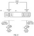
- the dispensers 150 A-Bare coupled with a network.
- Each of the dispensers 150 A-Bmay be coupled with the network over a wide area network (WAN) link (e.g., cellular (CDMA, GRPS, etc.), WiFi Internet connection, Plain Old Telephone Service, leased line, etc.), or one of the dispensers may be coupled with the network over a WAN link and coupled with the other dispenser over a LAN link (e.g., Wireless Personal Area Network (WPAN) such as Bluetooth, Zigbee, etc., Ethernet, Power Line Communication (PLC), WiFi, etc.) and relay messages between the other dispenser and the network.
- the networkmay include one or more servers that provide services for electric vehicle charging such as authorization service, accounting service, and reporting service.
- the networkmay store vehicle operator information (e.g., operator account information, operator contact information (e.g., operator name, street address, email address, telephone number, etc.)), charging session information (e.g., the duration that an EV connected to a dispenser has been charging; the duration that an EV connected to a dispenser has been parked in proximity to the dispenser; the time remaining on each charging session; the type of account associated with each charging session; the amount of current drawn by the EV during the session; the percentage of charge complete of the EV during the session; the percentage of charge remaining of the EV; the battery temperature of the EV during the session; the type of EV during the session; and/or a reservation status of the EV), dispenser configuration information (e.g., the wiring group the dispenser belongs to (as used herein, a wiring group corresponds to the physical wiring connection to the dispenser), the capacity of the wiring group (e.g., the breaker size), and/or a trip margin used to prevent false circuit breaker trips), load supply condition information, and/or power module
- Each dispenser 150 A-Bis configured to control the application of power to the electric vehicles, which may dynamically change as detailed herein.
- Each dispenser 150 A-Bis capable of being connected to an electric vehicle such as the electric vehicles 170 A-B respectively.
- the dispensersmay support a wired connection for attached charging cords (e.g., with a connector conforming to SAE Electric Vehicle and Plug in Hybrid Electric Vehicle Conductive Charge Coupler (J1772_201602), February 2016 (“SAE J 1772”); a connector conforming to the CHAdeMO protocol) for charging electric vehicles, connector capable of connecting to Tesla MotorsTM vehicles, a GB connector, and/or any other connector that attaches to an electric vehicle); and/or wireless charging (e.g., the dispensers may support inductive charging, and/or conductive charging (e.g., pantograph)).
- FIG. 1Billustrates an exemplary system 102 for dynamically allocating power modules for charging electric vehicles according to an embodiment.
- the system 102is similar to the system 100 but instead of having two distinct power buses, the system 102 has a single output bus to the DC output terminals 135 A-B (over the bus 190 A-B respectively).
- either all of the power modules 115 A-Dare allocated to a single dispenser or none of the power modules are allocated.
- either all of the power modules 115 A-Dcan be allocated to the dispenser 150 A or none of the power modules 115 A-D can be allocated to the dispenser 150 A at a given time.
- the dispenser(or device connected to the dispenser such as a payment station) includes an RFID reader
- the operatormay wave/swipe the mobile communication (if an RFID enabled device) near the RFID reader to request a charging session.
- the dispensermay forward information read from the RFID reader (e.g., an identifier associated with the electric vehicle operator) to the network for authentication.
- the networkdetermines whether to grant the charging session and replies to the dispenser with the response (e.g., allowed or denied).
- the dispensermay locally store authorization information (e.g., a whitelist or blacklist of identifiers) that allows the dispenser to determine whether to authorize the charging session.
- an electric vehicle operatormay use a mobile application on a mobile device to request a charging session on the dispenser.
- the operatormay select the dispenser using a locator map and then select to request a charging session (typically after logging into the application or otherwise providing user credentials to the application).
- the networkdetermines whether to grant the charging session and replies to the dispenser with the response (e.g., allowed or denied).
- the dispensermay be configured to allow for automatic authentication.
- An example of automatic authenticationincludes ISO 15118 where the electric vehicle operator requests a charging session by connecting their electric vehicle to the dispenser and that electric vehicle communicates an identifier (e.g., the vehicles VIN or other identifying information) that is used by the dispenser and/or the network to determine whether to grant or deny the charging session.
- automatic authenticationexamples include use of license plate recognition (the license plate may be read by the dispenser or other device coupled with the dispenser and the number used to determine whether to grant or deny the charging session), facial recognition (the dispenser, or other device coupled with the dispenser, may include a camera to take an image of the electric vehicle operator to determine whether a charging session for the electric vehicle operator should be granted or denied), proximity detection (e.g., WiFi, Bluetooth, Bluetooth LE) that detects whether a mobile device of the electric vehicle operator or the vehicle itself is in proximity to the electric vehicle and use an associated identifier to determine whether to grant or deny the charging session.
- license plate recognitionthe license plate may be read by the dispenser or other device coupled with the dispenser and the number used to determine whether to grant or deny the charging session
- facial recognitionthe dispenser, or other device coupled with the dispenser, may include a camera to take an image of the electric vehicle operator to determine whether a charging session for the electric vehicle operator should be granted or denied
- proximity detectione.g., WiFi, Bluetooth, Bluetooth LE
- the electric vehicle and the dispensercommunicate after being connected.
- the dispensermay advertise the available power to the vehicle, which is sometimes referred to as the maximum available continuous current capacity. This advertisement may take the form of modulating a signal (e.g., a control pilot signal).
- the amount of power that may be availablemay be determined by the dispenser based at least in total site feed and/or demand response information received from the network and/or the amount of power allocated from the group of power modules 115 A-D.
- the electric vehiclemay indicate a desired amount of power it wants to draw, which may change throughout the charging cycle (e.g., the electric vehicle may send a current command to the dispenser that the dispenser can use to determine how much power to supply to the electric vehicle).
- the requesting dispenserdetermines the status of the power modules 115 A-D. For instance, the requesting dispenser accesses the status of its local power modules and requests the status of the power modules of the other dispenser. As an example, if the dispenser 150 A is the requesting dispenser, it may access the status of the power modules 115 A-B and request the status of the power modules 115 C-D from the dispenser 150 B.
- the status of each power module 115 A-Dmay indicate whether the power module is currently allocated (e.g., whether it is currently connected to a power bus and may indicate which power bus), whether the power module is idle (e.g., not currently connected to a power bus), or whether the power module is offline (e.g., it cannot be contacted).
- the dispensermay request the status of a power module directly or may send a request to the PCU which then queries the status of the power modules. For instance, the dispenser 150 A may request the status of the power modules 115 C-D or may send a request to the PCU 120 B to query the status of the power modules 115 C-D and return the statuses to the dispenser 150 A.
- each power module 115 A-Dmay include an amount of time each power module has been operating.
- each dispenser 150 A-Bperiodically shares the status information of its respective power modules 115 A-D with each other and/or to the network (e.g., when the state of one of the power modules changes); which is used by the dispensers to determine the amount of power allocated from the group of power modules 115 A-D.
- the requesting dispensermay determine which, if any, power module, is currently available, using the power module status information. In such an embodiment, the dispenser requests allocation of certain ones of the available power modules so that the dispenser can charge the connected electric vehicle.
- the requesting dispensermay send a command to each one of the selected available power modules 115 A-D directly (which may be relayed by the PCU 120 A-B) that instructs the selected power module to switchably connect to the power bus that is connected to the dispenser.
- the dispenser 150 Amay cause the selected ones of the power modules 115 A-D to switchably connect to the power bus 140 A.
- the dispenser 150 Amay send a command to the dispenser 150 B (e.g., processed by the PCU 120 B of the dispenser 150 B) that instructs the dispenser 150 B to switchably connect the power modules 115 C-D to the power bus 140 A.
- the requesting dispensersends a request for power among the dispensers.
- each power module that is available to be allocated to the dispenseris then allocated.
- each available power module(at least of the power module group that can be allocated to the requesting dispenser) is allocated to the requesting power module, regardless of whether the electric vehicle and/or the dispenser can support supplying power to that amount.
- the amount of powermay be more than the dispenser and/or the electric vehicle can support.
- the dispensermay determine whether to release any of the power modules, such as the excess number of power modules that it does not need.
- the requesting dispensersends a request for power among the power modules of the dispensers. If all of the power modules are available, the request can be fulfilled and the power modules may be all be allocated to the requesting dispenser. If the power modules are not available, the request cannot be filled and the power modules will not be immediately allocated to the requesting dispenser. If there is more than one dispenser requesting use of the power modules at a time, a time sharing process may be used where the allocation of the power modules take turns between the multiple dispenser.
- the amount of power that the power modules 115 A-D can supply to the dispensers 150 A-Bmay not be enough to handle the maximum rating of the connected dispensers or the maximum capability of electric vehicles connected to those dispensers.
- the total amount of power that can be supplied by the power modules 115 A-Dmay be 125 kW, and each of the dispensers 150 A-B may be rated to dispense 125 kW.
- the sum of the power draw of the dispensers 150 A-Bshould be less than or equal to the total amount of power that can be supplied by the power modules 115 A-D.
- the electric vehiclescannot both receive their maximum capability as that would exceed the total amount of power that can be supplied by the power modules 115 A-D.
- the allocation of the power modules 115 A-D between the dispensers 150 A-Bcan be done differently in different embodiments.
- the allocationmay be done on a first-come first-served basis.
- the allocationmay be done on a round-robin basis.
- the allocationmay be done dynamically and be based on a set of one or more factors.
- FIG. 2illustrates an example of allocating power modules according to an embodiment.
- the EV 170 Ais capable of drawing 125 kW
- the EV 170 Bis capable of drawing 90 kW
- the total amount of power that can be supplied by the power modules 115 A-Dis 125 kW (each power module being capable of supplying 31.25 kW).
- the EV 170 Aarrives and connects to the dispenser 150 A at a time 1 .
- the EV 170 Bis not connected to the dispenser 150 B.
- the group of power modules 220(the power modules 115 A-D) are allocated to the dispenser 150 A and are capable of supplying the maximum power capability of the EV 170 A (125 kW).
- the power modules 115 A-Dare switchably connected to the power bus 140 A.
- the dispenser 150 Adetermines that each of the power modules 115 A-D are available including accessing the status of the power modules 115 A-B (the status of the power modules 115 A-B may be stored locally to the dispenser 150 A) and requesting the status of the power modules 115 C-D.
- the requestmay be sent after the EV 170 A is connected to the dispenser 150 A and after the desired amount of power is determined for the EV 170 A.
- the requestmay be sent prior to the EV 170 A arriving to the dispenser 150 A. For instance, if the EV 170 A has a reservation at the dispenser 150 A, the dispenser 150 A may send the request for power at a time prior to and proximate to the reservation time.
- the dispenser 150 Amay release the allocated power modules.
- the dispenser 150 Amay send the request for power at a time when the EV 170 A is determined to be near the dispenser 150 A.
- the EV 170 Barrives and is connected to the dispenser 150 B.
- the EV 170 Ais still connected to the dispenser 150 A and the group of power modules 220 are switchably connected to the power bus 140 A.
- the power modules 115 A-Dare not available to be allocated to the dispenser 150 B.
- the dispenser 150 Beither waits until a power module 115 A-D is available or requests a power module(s) be freed by the dispenser 150 A and allocated to the dispenser 150 B. If the EV 170 A becomes disconnected from the dispenser 150 A and/or finishes charging, the group of power modules 220 may become available and switchably disconnected from the power bus 140 A.
- the allocation of the power modules 115 A-D to the dispensers 150 A-Bis dynamic.
- FIG. 3illustrates an example of allocating power modules dynamically according to an embodiment.
- the example of FIG. 3is an extension of the example of FIG. 2 .
- the number of power modules allocated to the dispenser 150 Ais reduced.
- the power modules 115 B-D, previously allocated to the dispenser 150 Aare deallocated from the dispenser 150 A (e.g., switchably disconnected from the power bus 140 A).
- the remaining group of power modules 320(the power module 115 A) remain allocated to the dispenser 150 A.
- the amount of power that is capable of being drawn through the dispenser 150 Ahas been reduced from 125 kW to 31.25 kW.
- the power modules 115 B-DAfter deallocating the power modules 115 B-D from the dispenser 150 A, those power modules are available to be allocated to a different dispenser (e.g., the dispenser 150 B).
- the number of power modules allocated to the dispenser 150 Bis increased.
- the power modules 115 B-Dare allocated to the dispenser 150 B (e.g., switchably connected to the power bus 140 B) and is part of the group of power modules 325 allocated to the dispenser 150 B (the power modules 115 B-D).
- the amount of power that is capable of being drawn through the dispenser 150 Bhas been increased from 0 kW to 93.75 kW.
- the decision to dynamically allocate the power modulesmay be done differently in different embodiments.
- the power modulesmay be allocated across the different dispensers such that each of the dispensers are allocated at least some power modules (assuming that an EV is connected to the dispenser and is ready to accept energy), where the allocation may be on-demand (that is only if an electric vehicle is connected to that dispenser and requesting service).
- the power module allocationcan be dynamically adjusted (either increased or decreased) to a particular dispenser based on a set of one or more factors.
- the set of factorsmay include one or more properties of active charging sessions on the dispensers, one or more properties of the dispensers (e.g., the maximum rate of power that can be dispensed by each dispenser, the current rate of power that is being dispensed by each dispenser, the number of dispensers that are requesting to provide charging service, the number of electric vehicle(s) expected to arrive at the dispenser), and load condition information.
- properties of the dispenserse.g., the maximum rate of power that can be dispensed by each dispenser, the current rate of power that is being dispensed by each dispenser, the number of dispensers that are requesting to provide charging service, the number of electric vehicle(s) expected to arrive at the dispenser
- load condition informatione.g., the maximum rate of power that can be dispensed by each dispenser, the current rate of power that is being dispensed by each dispenser, the number of dispensers that are requesting to provide charging service, the number of electric vehicle(s) expected to arrive at the dispenser
- the one or more properties of the active charging sessionsmay include one or more of: the duration that each electric vehicle connected to the dispensers has been charging; the duration that each electric vehicle connected to the dispensers has been parked in proximity to the dispensers; the time remaining on each charging session; the type of account associated with each charging session; the amount of current drawn by each electric vehicle connected to the dispensers; the percentage of charge complete of each electric vehicle connected to the dispensers; the percentage of charge remaining of each electric vehicle connected to the dispensers; the battery temperature of each electric vehicle connected to the dispensers; the type of each electric vehicle connected to the dispensers; and a reservation status of each electric vehicle connected to the dispensers.
- the duration that the electric vehicles connected to the dispensers have been chargingmay be taken into consideration when determining how to dynamically allocate power modules between those dispensers. For instance, a dispenser connected to an electric vehicle that has been charging longer may be allocated less power modules than a dispenser connected to an electric vehicle that has been charging relatively lesser.
- the duration that the electric vehicles connected to the dispensers have been parked in proximity to the dispensermay be taken into consideration when determining how to dynamically allocate power modules between those dispensers. For instance, a dispenser connected to an electric vehicle that has been parked in proximity to the dispenser longer may be allocated less power modules than a dispenser connected to an electric vehicle that has been parked in proximity to the dispenser for a smaller amount of time.
- the time remaining on the charging sessionsmay be taken into consideration when determining how to dynamically allocate power modules between those dispensers. For instance, the allocation of power modules may prioritize charging sessions that are about to end.
- the type of account associated with the charging sessionsmay be taken into consideration when determining how to dynamically allocate power modules between those dispensers. For example, a charging session associated with an electric vehicle operator that is a member of a loyalty program of the host that owns or controls the dispensers may be prioritized over a charging session associated with an electric vehicle operator that is not a member of the loyalty program. As another example, a charging session associated with an electric vehicle operator that has paid a premium for charging service may be prioritized over a charging session associated with an electric vehicle operator that has not paid a premium for charging service.
- the amount of current drawn by the electric vehicles connected to the dispensersmay be taken into consideration when determining how to dynamically allocate power modules between those dispensers. For instance, the allocation of power modules may prioritize a dispenser connected to an electric vehicle that has drawn less current than a dispenser connected to an electric vehicle that has drawn more current.
- the percentage of charge complete of the electric vehicles connected to the dispensersmay be taken into consideration when determining how to dynamically allocate power modules between those dispensers. For instance, the allocation of power modules may prioritize a dispenser connected to an electric vehicle that has a lower percentage of charge complete over a dispenser connected to an electric vehicle that has a higher percentage of charge complete.
- the percentage of charge remaining of the electric vehicles connected to the dispensersmay be taken into consideration when determining how to dynamically allocate power modules between those dispensers. For instance, the allocation of power modules may prioritize a dispenser connected to an electric vehicle that has a higher percentage of charge remaining over a dispenser connected to an electric vehicle that has a lower percentage of charge remaining.
- the battery temperature of the electric vehicles connected to the dispensersmay be taken into consideration when determining how to dynamically allocate power modules between those dispensers. Electric vehicles reduce their rate of charge when the battery temperature reaches a certain amount.
- the allocation of power modulesmay prioritize a dispenser connected to an electric vehicle that has a lower battery temperature over a dispenser connected to an electric vehicle that has a higher battery temperature.
- the type of the electric vehicles connected to the dispensersmay be taken into consideration when determining how to dynamically allocate power modules between those dispensers. For instance, the allocation of power modules may prioritize a dispenser connected to a battery only electric vehicle (BEV) over a dispenser connected to a plug-in hybrid electric vehicle (PHEV).
- BEVbattery only electric vehicle
- PHEVplug-in hybrid electric vehicle
- the make and/or model of the electric vehicles connected to the dispensersmay be taken into consideration when determining how to dynamically allocate power modules between those dispensers. For instance, the allocation of power modules may prioritize a dispenser connected to an electric vehicle of a certain make and/or model over a dispenser connected to an electric vehicle of a different make and/or model.
- a reservation status of the electric vehicles connected to the dispensersmay be taken into consideration when determining how to dynamically allocate power modules between those dispensers. For instance, an electric vehicle that has a valid reservation may be prioritized in the power module allocation over an electric vehicle that does not have a valid reservation.
- Load supply conditionsmay be taken into consideration when determining how to dynamically allocate power modules. For instance, in periods of high demand (sometimes referred to as a demand response event), a message may be received that indicates that a reduction of power needs to be made. This may cause the total number of allocated power modules to be decreased until the demand response ends.
- a demand response eventsometimes referred to as a demand response event
- the number of electric vehicle(s) expected to arrive at the dispenser(s)may be taken into consideration when determining how to dynamically allocate power modules between those dispensers. For example, if use history of the dispensers indicate that the dispensers are historically busy at a certain time (e.g., morning commute, afternoon commute), the power modules may be allocated between those dispensers to support maximum use of the dispensers (e.g., the power modules may be allocated equally between the dispensers). As another example, the predicted arrival of EVs (e.g., based on state of charge of the EV and vehicle navigation information provided by an in-dash navigation unit and/or an app of a mobile device of an EV operator) may be used to allocate the power modules between those dispensers.
- the predicted arrival of EVse.g., based on state of charge of the EV and vehicle navigation information provided by an in-dash navigation unit and/or an app of a mobile device of an EV operator
- the allocation of power modulesmay be performed different in different embodiments.
- the allocation of power modulesis performed by the group of dispensers connected themselves.
- the allocation of power modulesis performed by a server that is connected with the group of dispensers.
- the entity that determines the allocation of power moduleshas access to information that allows it to determine whether to dynamically adjust the allocation of power modules.
- This information(e.g., duration that each electric vehicle connected to the dispensers has been charging; duration that each electric vehicle connected to the dispensers has been parked in proximity to the dispensers; the time remaining on each charging session; the type of account associated with each charging session; the amount of current drawn by each electric vehicle connected to the dispensers; the percentage of charge complete of each electric vehicle connected to the dispensers; the percentage of charge remaining of each electric vehicle connected to the dispensers; the battery temperature of each electric vehicle connected to the dispensers; the type of each electric vehicle connected to the dispensers; a reservation status of each electric vehicle connected to the dispensers; the amount of power presently allocated to each dispenser (or the number of power modules presently allocated to each dispenser); the rate of power being dispensed by each dispenser; the number of electric vehicle(s) expected to arrive at the dispenser(s); and/or load condition information) may be stored and/or communicated between the group of dispensers themselves and/or the network.
- the group of dispensersdetermine how to allocate the power modules, upon a dispenser receiving a request for charging service (e.g., an electric vehicle becomes connected to the dispenser), the dispenser determines the status of the power modules as previously described. The status may also include an amount of time each power module has been operating. The dispenser uses the status information of the power modules when determining how to allocate the power modules.
- a request for charging servicee.g., an electric vehicle becomes connected to the dispenser
- FIG. 4is a flow diagram that illustrates exemplary operations for allocating power modules according to an embodiment.
- the operations of FIG. 4will be described with respect to the exemplary embodiments of the other figures. However, it should be understood that the operations of FIG. 4 can be performed by embodiments other than those discussed with reference to the other figures, and the embodiments discussed with reference to these other figures can perform operations different than those discussed with reference to FIG. 4 .
- a dispenserreceives a request to initiate charging service for an electric vehicle that is connected to the dispenser.
- Different electric vehiclesmay desire to draw different amount of power.
- the EV 170 Ais capable of drawing 125 kW and the EV 170 B is capable of drawing 90 kW.
- the request to initiate charging servicemay indicate the desired amount of power draw.
- An electric vehicle operatormay specify the desired amount of power draw.
- the desired amount of power drawmay be determined based on the model/make of the electric vehicle (which may be stored in association with an account of the electric vehicle operator requesting the charging service).
- the electric vehicletransmits the requested power draw to the dispenser. Flow then moves to operation 415 .
- the dispenserdetermines the amount of power that is available for charging service for the electric vehicle.
- the dispenser 150 Amay access the status of the power modules 115 A-B and request the status of the power modules 115 C-D from the dispenser 150 B.
- the dispenser 150 Amay send the status request to the PCU 120 B which then queries the status of the power modules 115 C-D and returns the statuses to the dispenser 150 A.
- the status of each power module 115 A-Dmay include an amount of time each power module has been operating.
- the status of each power module 115 A-Dmay indicate the amount of power that can be supplied by that power module.
- the status information of the power modules 115 A-Dis locally available to the dispenser 150 A (e.g., the dispenser 150 B may periodically send status information of the power modules 115 C-D such as when the state of those power modules change) and/or available on the network.
- flowmoves to operation 420 .
- the dispenserdetermines whether the amount of available power for charging the electric vehicle is enough to meet the requested or determined amount of power draw of the electric vehicle. For instance, the dispenser compares the amount of available power for charging the electric vehicle with the requested or determined amount of power draw for the electric vehicle. If there is enough available power for charging the electric vehicle, then flow moves to operation 430 . If there is not enough available power for charging the electric vehicle, then flow moves to operation 425 . For instance, in FIG. 2 , there are enough power modules available to fully meet the power capability of the EV 170 A when it is the only EV that is drawing power from the power modules 115 A-D.
- the dispenserselects the power modules to meet the requested or determined amount of power draw.
- the dispenseronly selects the power modules that have a status of available. That is, the dispenser does not select from a power module that is currently allocated to another dispenser. From the available power modules, the dispenser may select those power module(s) that have the relatively lowest operating time. The dispenser may transmit the identification of the selected power modules to the other dispenser(s) connected and/or to the network. Flow then moves to operation 435 .
- the dispenserinstead of the dispenser selecting the power modules, the dispenser requests a number of power modules from the network and the network selects the requested number of power modules and causes them to be allocated accordingly.
- the dispenserrequests allocation of the selected power modules.
- the requesting dispensercauses the selected power module to switchably connect to the power bus that is connected to the dispenser.
- the dispenser 150 Amay cause the power modules 115 A-B to switchably connect to the power bus 140 A and send a command to the dispenser 150 B to cause the power modules 115 C-D to switchably connect to the power bus 140 A.
- Flowthen moves to operation 440 where charging service commences.
- the dispenserrequests deallocation of the allocated power modules.
- the charging servicemay end as a result of the charging session ending (e.g., the electric vehicle being disconnected from the dispenser).
- the requesting dispensermay send a command to each one of the allocated power modules directly (which may be relayed by the PCU) that causes the allocated power module to switchably disconnect from the power bus that is connected to the dispenser.
- the dispenser 150 Acause the power modules 115 A-B to switchably disconnect from the power bus 140 A and send a command to the dispenser 150 B to cause the power modules 115 C-D to switchably disconnect from the power bus 140 A.
- the requesting dispensermay send a command to the network that indicates that the dispenser has finished charging service and any allocated power module(s) may be deallocated from the dispenser 150 B.
- any allocated power module(s)may be deallocated from the dispenser 150 B.
- when a power module is deallocatedit may be switchably disconnected from the power bus immediately.
- when a power module is deallocatedit is not switchably disconnected from the power bus unless and until a determination has been made to allocate that power module to another dispenser.
- the dispenserdetermines whether there is any power available for charging of the electric vehicle. If there is, then flow moves to operation 445 where the dispenser requests allocation of the remaining power modules, in a similar way as described with respect to operation 435 . Flow then moves from operation 445 to operation 440 . If there is not any power available, then flow moves to operation 450 where an alternative action is taken.
- the dispensermay periodically determine the status of each power module to determine when there is power available for charging the EV.
- the other dispenser(s) that have been allocated power module(s)may periodically send status information of the power modules to the dispenser and/or to the network that can be accessed or transmitted to the dispenser.
- Another alternative actionis a dynamic allocation of the power modules where one or more power modules are deallocated from a different dispenser and allocated to the requesting dispenser.
- the dynamic allocationmay be based on a set of one or more factors as previously described, and a set of predefined allocation rules.
- the dynamic allocation of the power modulesis performed by the group of dispensers themselves.
- the dynamic allocation of power modulesis performed by a server that is connected with the group of dispensers.
- FIG. 5is a flow diagram that illustrates exemplary operations for dynamic allocation of the power modules according to an embodiment.
- the operations of FIG. 5will be described with respect to the exemplary embodiments of the other figures. However, it should be understood that the operations of FIG. 5 can be performed by embodiments other than those discussed with reference to the other figures, and the embodiments discussed with reference to these other figures can perform operations different than those discussed with reference to FIG. 5 .
- the determination to dynamically allocate the power modulesmay be made as a result of the sum of the requested power draw of the connected dispensers exceeding the maximum amount supported by the group of power modules.
- a dispenser that is allocated a power moduleis periodically checked whether it is utilizing its allocated power module(s), and if it is not utilizing its allocated power module(s), those power module(s) are deallocated and allocated to a different dispenser (if that dispenser has need for those power module(s)). For instance, an electric vehicle may ramp down its power usage as it is nearing charging completion, although it may still be connected to the dispenser.
- the EVmay indicate to the dispenser the rate of power that it currently desires (e.g., the EV may send a current command to the dispenser that can be used to determine how much power to supply to the EV).
- the rate of power that is being dispensed through an EVis measured, and that measured amount is compared against the allocated power amount to determine whether the allocated power module(s) are being utilized.
- the metrology componentmay be included within each dispenser or coupled with each dispenser.
- one or more of the dispensers that are currently allocated one or more power modulesare selected to have one or more power modules be deallocated and reallocated to a different dispenser.
- the number of power module(s) currently allocated to the selected dispenser(s) to be deallocated and reallocated to a different dispenseris determined.
- the decision to select a dispenser for power module deallocation, and/or the selection of the number of power module(s) to be deallocatedmay take into consideration one or more factors, such as the duration that each electric vehicle connected to the dispensers has been charging; the duration that each electric vehicle connected to the dispensers has been parked in proximity to the dispensers; the time remaining on each charging session; the type of account associated with each charging session; the amount of current drawn by each electric vehicle connected to the dispensers; the percentage of charge complete of each electric vehicle connected to the dispensers; the percentage of charge remaining of each electric vehicle connected to the dispensers; the battery temperature of each electric vehicle connected to the dispensers; the type of each electric vehicle connected to the dispensers; a reservation status of each electric vehicle connected to the dispensers; the amount of power presently allocated to each dispenser (or the number of power modules presently allocated to each dispenser); the rate of power being dispensed by each dispenser; the number of electric vehicle(s) expected to arrive at the dispenser(s); and/or load condition information.
- the selected number of power module(s) for deallocationare deallocated from dispenser(s) in which it is currently connected, and reallocated to another dispenser.
- the power modules 115 B-D that were previously allocated to the dispenser 150 Aare deallocated (e.g., switchably disconnected from the power bus 140 A) and allocated to the dispenser 150 B (e.g., switchably connected to the power bus 140 B).
- a messagemay be sent from the dispenser to that power module directly (which may be relayed by the PCU) that instructs the power module to switchably disconnect from the power bus. That dispenser may also instruct the power module to be allocated to a different dispenser.
- the dispenser that is deallocating the power modulemay send a message to the dispenser that will be allocated that power module that indicates that the power module has been instructed to be disconnected.
- the dispenser that will be allocated that power modulemay then send a message to the power module that causes the power module to be switchably connected to the power bus connecting the dispenser with its output.
- a dispensersends a request for power and the available power modules are allocated to the dispenser, regardless of whether the amount of allocated power exceeds the requested or supported amount of power. If the dispenser is allocated an excess amount of power, the dispenser releases the excess power module(s) so that they can be allocated to a different dispenser.
- FIG. 6is a flow diagram that illustrates exemplary operations for allocating power modules according to an embodiment. The operations of FIG. 6 will be described with respect to the exemplary embodiments of the other figures. However, it should be understood that the operations of FIG. 6 can be performed by embodiments other than those discussed with reference to the other figures, and the embodiments discussed with reference to these other figures can perform operations different than those discussed with reference to FIG. 6 .
- a dispensermakes a request for power.
- the requestmay be made in reaction to an electric vehicle being connected to the dispenser.
- the requestmay be made proactively such as based upon a reservation time of the dispenser nearing (within a predetermined time of the reservation time) or through determining a likelihood that an electric vehicle will be arriving at the dispenser (e.g., through history of use or through use of navigation and state of charge of the EV).
- the request for powermay be sent to each of the dispensers that share power modules and/or to the network. Any available power modules will be allocated to the requesting dispenser in this example.
- the dispenserreceives a message that indicates an allocation of one or more power modules.
- the messagemay include information about the allocated power modules (e.g., an identifier of each power module that has been allocated to the dispenser, an amount of time each allocated power module has been operating, and/or the amount of power that can be dispensed by each allocated power module).
- the number of power modules and corresponding powermay exceed the requested/determined or supported amount of power draw from the electric vehicle connected to the dispenser or expected to be connected to the dispenser.
- the dispenserdetermines whether the number of allocated power modules exceed the requested or determined amount of power draw for the electric vehicle. For instance, the dispenser compares the amount of allocated power with the requested or determined amount of power draw for the electric vehicle. For instance, with respect to FIG. 2 , if the dispenser 150 A is initially allocated all of the power modules 115 A-D and each is capable of supplying 31.25 kW (a total of 125 kW), the total amount of power (125 kW) does not exceed the amount of power that is capable of being drawn by the EV 170 A (125 kW). If the amount of allocated power modules exceed the requested or determined amount of power draw for the EV, then flow moves to operation 630 . If the amount of allocated power modules does not exceed the requested or determined amount of power draw for the EV, then flow moves to operation 640 .
- the dispenserselects one or more power modules to release such that the total amount of power does not exceed the requested or determined amount of power draw for the EV. In an embodiment, the dispenser selects the power modules to release that have the most amount of operating hours. Flow then moves to operation 635 where the dispenser causes the deallocation of the selected power modules. For those selected power module(s) that are included within the dispenser, the dispenser may switchably disconnect those power module(s) from the power bus. For those selected power module(s) that are included in another dispenser, a command may be sent to the other dispenser that instructs that dispenser to switchably disconnect those power module(s) from the power bus. In an embodiment, when a power module is deallocated, it may be switchably disconnected from the power bus immediately.
- a power modulewhen a power module is deallocated, it is not switchably disconnected from the power bus unless and until a determination has been made to allocate that power module to another dispenser. Flow then moves to operation 640 , where charging service commences. In an embodiment, commencing of the charging service of operation 640 may be prior to the operation 630 . Flow moves from operation 640 to operation 650 .
- the dispenserupon charging service ending, causes the deallocation of the allocated power modules.
- the charging servicemay end as a result of the charging session ending (e.g., the electric vehicle being disconnected from the dispenser).
- the dispensermay switchably disconnect those power module(s) from the power bus.
- a commandmay be sent to the other dispenser that instructs that dispenser to switchably disconnect those power module(s) from the power bus.
- a power modulewhen a power module is deallocated, it may be switchably disconnected from the power bus immediately. In another embodiment, when a power module is deallocated, it is not switchably disconnected from the power bus unless and until a determination has been made to allocate that power module to another dispenser.
- a dynamic reallocation of power modulesmay be performed, such as described with respect to FIG. 5 .
- the number of power module(s) that are allocated to dispenser(s)may be determined dynamically.
- the particular power module(s) that will be selected for allocationis dynamically determined. For instance, the selection of power module(s) for allocation may be performed according to a load balancing algorithm such that the usage amongst the power modules is roughly equal. This helps preventing a power module from wearing out faster than others due to overuse.
- the operating hours of the available power modulesis determined and the power module with the lowest amount of operating hours is selected for allocation.
- deallocating a power moduleincludes disconnecting the power module from the power bus in which it is currently connected. A deallocated power module is then available to be allocated. In another embodiment, deallocating a power module does not include disconnecting the power module from the power bus in which it is currently connected unless and until a determination has been made to allocate that power module to another dispenser.
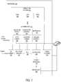
- FIG. 7illustrates an exemplary dispenser according to an embodiment.
- the dispensers 150 A-Bmay take the form of the dispenser 700 .
- the dispenser 700includes the operating system 710 that is coupled with the embedded microcontroller 715 .
- the operating system 710manages certain hardware and software for the dispenser 700 such as the WAN module 750 to manage a wide area network (WAN) connection for the dispenser 700 , the LCD module 755 to manage a display of the dispenser 700 , and the RFID module 760 that manages an RFID transceiver of the dispenser 700 .
- WANwide area network
- the embedded microcontroller 715executes the isolation detect module 765 , the contactor control module 770 , the metrology module 775 , the J1772 communications module 780 , the CHAdeMO communications module 785 , and the cooling control module 790 .
- the dispensermay include more, less, or different communication modules for communicating with different vehicle types.
- the isolation detect module 765manages the isolation sensor 725 to detect whether the circuits are isolated. For instance, with respect to a DC output, rail isolation is the resistance between each DC rail and ground including any measuring device, and total isolation is the parallel combination of both rail isolation values. The dispenser 700 will terminate a charge when the isolation of either rail to ground is under a certain amount.
- the PCU 728manages the dynamic allocation of the power module(s) 738 , as previously described herein.
- the contactor control module 770manages the contactor 730 including causing the contactor 730 to open and close as appropriate.
- the V/I sense component 720senses the current and voltage and provides the sensed data to the embedded microcontroller 715 .
- the metrology module 775manages the metrology component 740 that meters electrical usage (e.g., drawn by the electric vehicle).
- the J1772 communications module 780handles communications between the dispenser 700 and an electric car according to the J1772 standard.
- the CHAdeMO communications module 785handles communications between the dispenser 700 and an electric car according to the CHAdeMO standard.
- the cooling control module 790manages the cooling of the dispenser 700 including managing the cable cooling component 735 .
- the cable cooling component 735may control a liquid cable cooling system, and may monitor and control the flow rate, pressure, inlet, outlet temperature, cable temperature, and/or connector temperature of the charging cable.
- the techniques shown in the figurescan be implemented using code and data stored and executed on one or more electronic devices (e.g., a dispenser, a server).
- electronic devicesstore and communicate (internally and/or with other electronic devices over a network) code and data using machine-readable media, such as non-transitory machine-readable storage media (e.g., magnetic disks; optical disks; random access memory; read only memory; flash memory devices; phase-change memory) and transitory machine-readable communication media (e.g., electrical, optical, acoustical or other form of propagated signals—such as carrier waves, infrared signals, digital signals).
- machine-readable mediasuch as non-transitory machine-readable storage media (e.g., magnetic disks; optical disks; random access memory; read only memory; flash memory devices; phase-change memory) and transitory machine-readable communication media (e.g., electrical, optical, acoustical or other form of propagated signals—such as carrier waves, infrared signals, digital signals).
- such electronic devicestypically include a set of one or more processors coupled to one or more other components, such as one or more storage devices (non-transitory machine-readable storage media), user input/output devices (e.g., a keyboard, a touchscreen, and/or a display), and network connections.
- the coupling of the set of processors and other componentsis typically through one or more busses and bridges (also termed as bus controllers).
- bus controllersalso termed as bus controllers
- the storage device of a given electronic devicetypically stores code and/or data for execution on the set of one or more processors of that electronic device.
- one or more parts of an embodiment of the inventionmay be implemented using different combinations of software, firmware, and/or hardware.
- references in the specification to “one embodiment,” “an embodiment,” “an example embodiment,” etc.,indicate that the embodiment described may include a particular feature, structure, or characteristic, but every embodiment may not necessarily include the particular feature, structure, or characteristic. Moreover, such phrases are not necessarily referring to the same embodiment. Further, when a particular feature, structure, or characteristic is described in connection with an embodiment, it is submitted that it is within the knowledge of one skilled in the art to affect such feature, structure, or characteristic in connection with other embodiments whether or not explicitly described.
- Bracketed text and blocks with dashed bordersmay be used herein to illustrate optional operations that add additional features to embodiments of the invention. However, such notation should not be taken to mean that these are the only options or optional operations, and/or that blocks with solid borders are not optional in certain embodiments of the invention.
- Coupledis used to indicate that two or more elements, which may or may not be in direct physical or electrical contact with each other, co-operate or interact with each other.
Landscapes
- Engineering & Computer Science (AREA)
- Power Engineering (AREA)
- Transportation (AREA)
- Mechanical Engineering (AREA)
- Life Sciences & Earth Sciences (AREA)
- Sustainable Development (AREA)
- Sustainable Energy (AREA)
- Charge And Discharge Circuits For Batteries Or The Like (AREA)
- Electric Propulsion And Braking For Vehicles (AREA)
Abstract
Description
Claims (18)
Priority Applications (6)
| Application Number | Priority Date | Filing Date | Title |
|---|---|---|---|
| US15/605,857US10744883B2 (en) | 2016-05-25 | 2017-05-25 | Dynamic allocation of power modules for charging electric vehicles |
| US16/995,579US11135940B2 (en) | 2016-05-25 | 2020-08-17 | Dynamic allocation of power modules for charging electric vehicles |
| US16/995,613US11148551B2 (en) | 2016-05-25 | 2020-08-17 | Dynamic allocation of power modules for charging electric vehicles |
| US17/493,696US11813959B2 (en) | 2016-05-25 | 2021-10-04 | Dynamic allocation of power modules for charging electric vehicles |
| US17/493,684US11958380B2 (en) | 2016-05-25 | 2021-10-04 | Dynamic allocation of power modules for charging electric vehicles |
| US18/508,117US12221010B2 (en) | 2016-05-25 | 2023-11-13 | Dynamic allocation of power modules for charging electric vehicles |
Applications Claiming Priority (2)
| Application Number | Priority Date | Filing Date | Title |
|---|---|---|---|
| US201662341567P | 2016-05-25 | 2016-05-25 | |
| US15/605,857US10744883B2 (en) | 2016-05-25 | 2017-05-25 | Dynamic allocation of power modules for charging electric vehicles |
Related Child Applications (2)
| Application Number | Title | Priority Date | Filing Date |
|---|---|---|---|
| US16/995,579ContinuationUS11135940B2 (en) | 2016-05-25 | 2020-08-17 | Dynamic allocation of power modules for charging electric vehicles |
| US16/995,613DivisionUS11148551B2 (en) | 2016-05-25 | 2020-08-17 | Dynamic allocation of power modules for charging electric vehicles |
Publications (2)
| Publication Number | Publication Date |
|---|---|
| US20180001781A1 US20180001781A1 (en) | 2018-01-04 |
| US10744883B2true US10744883B2 (en) | 2020-08-18 |
Family
ID=60411887
Family Applications (6)
| Application Number | Title | Priority Date | Filing Date |
|---|---|---|---|
| US15/605,857Active2037-11-06US10744883B2 (en) | 2016-05-25 | 2017-05-25 | Dynamic allocation of power modules for charging electric vehicles |
| US16/995,579ActiveUS11135940B2 (en) | 2016-05-25 | 2020-08-17 | Dynamic allocation of power modules for charging electric vehicles |
| US16/995,613ActiveUS11148551B2 (en) | 2016-05-25 | 2020-08-17 | Dynamic allocation of power modules for charging electric vehicles |
| US17/493,696ActiveUS11813959B2 (en) | 2016-05-25 | 2021-10-04 | Dynamic allocation of power modules for charging electric vehicles |
| US17/493,684ActiveUS11958380B2 (en) | 2016-05-25 | 2021-10-04 | Dynamic allocation of power modules for charging electric vehicles |
| US18/508,117ActiveUS12221010B2 (en) | 2016-05-25 | 2023-11-13 | Dynamic allocation of power modules for charging electric vehicles |
Family Applications After (5)
| Application Number | Title | Priority Date | Filing Date |
|---|---|---|---|
| US16/995,579ActiveUS11135940B2 (en) | 2016-05-25 | 2020-08-17 | Dynamic allocation of power modules for charging electric vehicles |
| US16/995,613ActiveUS11148551B2 (en) | 2016-05-25 | 2020-08-17 | Dynamic allocation of power modules for charging electric vehicles |
| US17/493,696ActiveUS11813959B2 (en) | 2016-05-25 | 2021-10-04 | Dynamic allocation of power modules for charging electric vehicles |
| US17/493,684ActiveUS11958380B2 (en) | 2016-05-25 | 2021-10-04 | Dynamic allocation of power modules for charging electric vehicles |
| US18/508,117ActiveUS12221010B2 (en) | 2016-05-25 | 2023-11-13 | Dynamic allocation of power modules for charging electric vehicles |
Country Status (7)
| Country | Link |
|---|---|
| US (6) | US10744883B2 (en) |
| EP (3) | EP4137350A1 (en) |
| DK (1) | DK3463970T3 (en) |
| ES (1) | ES2924551T3 (en) |
| HR (1) | HRP20221179T1 (en) |
| PT (1) | PT3463970T (en) |
| WO (1) | WO2017205690A1 (en) |
Cited By (11)
| Publication number | Priority date | Publication date | Assignee | Title |
|---|---|---|---|---|
| US11110814B2 (en)* | 2018-08-02 | 2021-09-07 | Audi Ag | Charging device for electric vehicles |
| US11135940B2 (en) | 2016-05-25 | 2021-10-05 | Chargepoint, Inc. | Dynamic allocation of power modules for charging electric vehicles |
| US11198371B2 (en)* | 2018-08-31 | 2021-12-14 | AddÉnergie Technologies Inc. | Dual voltage range charging station |
| US11312260B1 (en)* | 2021-01-25 | 2022-04-26 | Blue Networks Co., Ltd. | Method for controlling charging capacity of electric vehicle charging terminal capable of charging specific electric vehicle, and server using the same |
| US11338695B2 (en)* | 2017-07-10 | 2022-05-24 | Abb Schweiz Ag | Variable power charging |
| US20220169134A1 (en)* | 2019-04-02 | 2022-06-02 | Envision Energy CO.,LTD | Method and system for controlling mobile charging device |
| US11433772B2 (en)* | 2016-03-23 | 2022-09-06 | Chargepoint, Inc. | Dynamic allocation of power modules for charging electric vehicles |
| US11772504B2 (en)* | 2019-08-22 | 2023-10-03 | Ioan Sasu | Fast rechargeable battery assembly and recharging equipment |
| US11780345B2 (en) | 2009-07-23 | 2023-10-10 | Chargepoint, Inc. | Managing electric current allocation between charging equipment for charging electric vehicles |
| US11951863B2 (en) | 2009-12-17 | 2024-04-09 | Chargepoint, Inc. | Method and apparatus for management of current load to an electric vehicle charging station in a residence |
| US20250004520A1 (en)* | 2023-06-30 | 2025-01-02 | Cisco Technology, Inc. | Power distribution and communication infrastructure for connected appliances |
Families Citing this family (30)
| Publication number | Priority date | Publication date | Assignee | Title |
|---|---|---|---|---|
| CN106564399B (en)* | 2016-11-11 | 2018-05-15 | 深圳市沃特玛电池有限公司 | Charging station |
| CN108400634B (en)* | 2018-02-09 | 2021-06-01 | 蔚来(安徽)控股有限公司 | Electric vehicle charging control device and method |
| DE102018104408B4 (en)* | 2018-02-27 | 2024-12-05 | Dr. Ing. H.C. F. Porsche Aktiengesellschaft | Method and system for recognizing a vehicle type of a vehicle |
| EP3656603A1 (en)* | 2018-11-23 | 2020-05-27 | Henrik Thiele | Charging station and system with vehicle presence sensor and authentication function |
| EP3689667A1 (en) | 2019-01-30 | 2020-08-05 | Green Motion SA | Electrical vehicle charging station with power management |
| MX392081B (en)* | 2019-03-26 | 2025-03-21 | Renewable Charging Solutions Llc | Method and apparatus for modular charging station |
| US11605954B2 (en)* | 2019-06-28 | 2023-03-14 | GM Cruise Holdings LLC. | Asymmetrical power output direct current fast charger |
| US11733056B2 (en)* | 2019-07-25 | 2023-08-22 | Volkswagen Aktiengesellschaft | Decentralized LMV charging infrastructure |
| CN112421739B (en)* | 2020-04-24 | 2024-01-02 | 葛炽昌 | Alternating-current charging system of electric vehicle |
| US11453298B2 (en) | 2020-05-08 | 2022-09-27 | Rivian Ip Holdings, Llc | Electric vehicle charging dispenser and method |
| US11565601B2 (en) | 2020-05-08 | 2023-01-31 | Rivian Ip Holdings, Llc | Electric vehicle charging system and method |
| US11628739B2 (en) | 2020-05-08 | 2023-04-18 | Rivian Ip Holdings, Llc | Electric vehicle fleet charging system and method |
| US11890951B2 (en) | 2020-05-08 | 2024-02-06 | Rivian Ip Holdings, Llc | Electric vehicle charging system and method utilizing a dispenser chain |
| US11868927B2 (en) | 2020-05-08 | 2024-01-09 | Rivian Ip Holdings, Llc | Electric vehicle charging system and method |
| EP4173108A1 (en)* | 2020-06-30 | 2023-05-03 | I-Charging, Mobilidade Electrica, S.A. | Intelligent charging system for electric vehicle batteries in direct current |
| US20220001762A1 (en)* | 2020-07-03 | 2022-01-06 | Blink Charging Co. | Portable electric generator for charging electric vehicles |
| US11368028B2 (en)* | 2020-09-16 | 2022-06-21 | Evq Technologies Private Limited | Facilitating charging of acceptor nodes by mobile charging systems |
| US12134326B2 (en)* | 2020-10-15 | 2024-11-05 | Rivian Ip Holdings, Llc | Charging station power sharing system and method |
| JP7480693B2 (en)* | 2020-12-22 | 2024-05-10 | トヨタ自動車株式会社 | Server, vehicle, and vehicle diagnosis method |
| GB2603902A (en)* | 2021-02-15 | 2022-08-24 | Peter Boxwell Michael | Improved power supply to charging stations for electric vehicles |
| FI20215667A1 (en)* | 2021-06-08 | 2022-12-09 | Liikennevirta Oy / Virta Ltd | Management extender for an electric vehicle charging point |
| JP7589648B2 (en)* | 2021-06-17 | 2024-11-26 | トヨタ自動車株式会社 | Ground power supply device and power supply method |
| CN113580985A (en)* | 2021-07-20 | 2021-11-02 | 贵安新区配售电有限公司 | Regular polygon preemptive electric vehicle charging circuit and method for distributing power according to needs and charging pile |
| US11628732B2 (en)* | 2021-07-29 | 2023-04-18 | Rivian Ip Holdings, Llc | Controllers, devices, and methods for performing power quality control using direct current fast charging devices |
| US20230104996A1 (en) | 2021-10-06 | 2023-04-06 | Geotab Inc. | Methods for controlling power distribution to vehicles |
| US20230117407A1 (en)* | 2021-10-19 | 2023-04-20 | Chargepoint, Inc. | Dynamic allocation of power modules for charging electric vehicles |
| US12165224B2 (en)* | 2021-12-10 | 2024-12-10 | Kyndryl, Inc. | Electric vehicle charging reservation timeslot reallocation |
| PL246039B1 (en)* | 2022-05-27 | 2024-11-25 | Euroloop Spolka Z Ograniczona Odpowiedzialnoscia | DC charger for electric vehicles |
| US11784491B1 (en) | 2022-07-15 | 2023-10-10 | Geotab Inc. | Systems and methods for implementing vehicle charging infrastructure |
| US12141017B2 (en) | 2022-08-31 | 2024-11-12 | Acleap Power Inc. | Systems and methods for coordinating power delivery in a modular multi-phase power delivery system |
Citations (77)
| Publication number | Priority date | Publication date | Assignee | Title |
|---|---|---|---|---|
| US3824813A (en) | 1973-02-26 | 1974-07-23 | Gen Motors Corp | Power supply control circuit for 120 volt combination washer and dryer |
| US5307001A (en) | 1992-05-05 | 1994-04-26 | Dimensions Unlimited, Inc. | Battery charging method and apparatus |
| US5327066A (en) | 1993-05-25 | 1994-07-05 | Intellectual Property Development Associates Of Connecticut, Inc. | Methods and apparatus for dispensing a consumable energy source to a vehicle |
| US5550465A (en) | 1994-05-23 | 1996-08-27 | Nippondenso Co., Ltd. | Driving apparatus for cross-coil type analog indicating instrument |
| US5594318A (en) | 1995-04-10 | 1997-01-14 | Norvik Traction Inc. | Traction battery charging with inductive coupling |
| US5656916A (en) | 1994-08-25 | 1997-08-12 | Honda Giken Kogyo Kabushiki Kaisha | Apparatus for controlling the currents supplied for battery charging and an electric load during charging of an electric vehicle battery |
| US5696367A (en) | 1993-04-19 | 1997-12-09 | Keith; Arlie L. | Charging batteries of electric vehicles |
| US5814972A (en) | 1993-05-13 | 1998-09-29 | Canon Kabushiki Kaisha | Electronic apparatus having multiple loads, driven by plural batteries |
| US5982596A (en) | 1998-05-05 | 1999-11-09 | George Authur Spencer | Load center monitor and digitally enhanced circuit breaker system for monitoring electrical power lines |
| US6067008A (en) | 1993-05-25 | 2000-05-23 | Intellectual Property Development Associates Of Connecticut, Inc. | Methods and apparatus for inputting messages, including advertisements, to a vehicle |
| US6087805A (en) | 1995-04-14 | 2000-07-11 | Langston; Charles R. | Monitoring and controlling system for battery and battery charger |
| US6114775A (en) | 1997-10-27 | 2000-09-05 | Mando Machinery Corporation | Control system of auxiliary power system for a hybrid electric vehicle |
| US6137070A (en) | 1998-07-01 | 2000-10-24 | General Electric Company | Circuit breaker assembly with inhibitor assembly |
| US6225776B1 (en) | 2000-08-03 | 2001-05-01 | Wellmon Chai | Charging station for electric-powered vehicles |
| US20030052547A1 (en) | 2001-03-01 | 2003-03-20 | Fischer Daniel M. | Multifunctional charger system and method |
| US6614204B2 (en) | 2001-12-21 | 2003-09-02 | Nicholas J. Pellegrino | Charging station for hybrid powered vehicles |
| US6646561B1 (en) | 2000-10-06 | 2003-11-11 | Battery Alert Ltd. | Method and device for in-use detecting low cranking strength of a combustion engine battery during engine starting |
| US6680547B1 (en) | 2002-08-01 | 2004-01-20 | Innovations Electrical, Lc | Power sharing system including rechargeable power source |
| US20040042138A1 (en) | 2002-08-30 | 2004-03-04 | Seiko Epson Corporation | Data transfer control device, electronic equipment, and power supply switching method |
| US20040130292A1 (en) | 2000-06-14 | 2004-07-08 | Buchanan William D. | Battery charging system and method |
| US20050099131A1 (en) | 2001-08-10 | 2005-05-12 | Amarillas Sal G. | Electrical power conservation apparatus and method |
| US20060108971A1 (en) | 2004-11-19 | 2006-05-25 | Denso Corporation | Method and apparatus for managing state of in-vehicle battery |
| US7071698B2 (en) | 2004-03-30 | 2006-07-04 | Sany Electric Co., Ltd. | Power supply apparatus for detecting battery voltage and the portions of faults |
| WO2008142431A1 (en) | 2007-05-23 | 2008-11-27 | Onzo Limited | Energy meter with power source |
| US20090021213A1 (en) | 2007-07-20 | 2009-01-22 | Oriz Wickline Johnson | Method for pay-per-use, self-service charging of electric automobiles |
| US7486034B2 (en) | 2005-08-08 | 2009-02-03 | Toyota Jidosha Kabushiki Kaisha | Power supply device for vehicle and method of controlling the same |
| US20090040029A1 (en) | 2006-08-10 | 2009-02-12 | V2Green, Inc. | Transceiver and charging component for a power aggregation system |
| US20090045676A1 (en) | 2007-08-13 | 2009-02-19 | Glenn Rosendahl | Controlling Power Supply to Vehicles Through a Series of Electrical Outlets |
| US20090066287A1 (en) | 2006-08-10 | 2009-03-12 | V2Green, Inc. | Business Methods in a Power Aggregation System for Distributed Electric Resources |
| WO2009034918A1 (en) | 2007-09-10 | 2009-03-19 | Toyota Jidosha Kabushiki Kaisha | Automobile and method for charging automobile |
| US7602143B2 (en) | 2005-11-04 | 2009-10-13 | Peter David Capizzo | System for replenishing energy sources onboard different types of automotive vehicles |
| US20090261779A1 (en) | 2008-04-09 | 2009-10-22 | Intellon Corporation | Transmission line directional awareness |
| US20090282274A1 (en) | 2008-05-09 | 2009-11-12 | International Business Machines Corporation | Managing Power Consumption In A Data Center |
| US20090313098A1 (en) | 2008-06-16 | 2009-12-17 | International Business Machines Corporation | Network Based Energy Preference Service for Managing Electric Vehicle Charging Preferences |
| US20100017249A1 (en) | 2008-07-11 | 2010-01-21 | Fincham Carson C K | Systems and methods for electric vehicle charging and power management |
| US20100026237A1 (en) | 2006-11-08 | 2010-02-04 | Toyota Jidosha Kabushiki Kaisha | Motored vehicle and method of controlling voltage conversion device |
| US20100039062A1 (en) | 2008-08-18 | 2010-02-18 | Gong-En Gu | Smart charge system for electric vehicles integrated with alternative energy sources and energy storage |
| US20100066170A1 (en) | 2008-08-12 | 2010-03-18 | Mike Schuler | Method and Apparatus for Allocating Electricity from a Distributor |
| KR20100036896A (en) | 2008-09-30 | 2010-04-08 | 한양대학교 산학협력단 | Positive active material for rechargeable lithium battery and rechargeable lithium battery comprising same |
| US7719284B2 (en) | 2004-11-30 | 2010-05-18 | Keihin Corporation | Apparatus for measuring voltage |
| US20100141204A1 (en) | 2008-12-05 | 2010-06-10 | Tyler Richard M | Sub-network load management for use in recharging vehicles equipped with electrically powered propulsion systems |
| US7746049B2 (en) | 2007-03-30 | 2010-06-29 | Canon Kabushiki Kaisha | Power supply device and recording apparatus |
| US20100181957A1 (en) | 2008-09-19 | 2010-07-22 | Christoph Goeltner | Solar powered, grid independent EV charging system |
| US7812469B2 (en) | 2006-12-12 | 2010-10-12 | Denso Corporation | Battery current detection apparatus incorporated in system which regulates vehicle engine speed and electric generator output voltage during engine idling |
| US7834613B2 (en) | 2007-10-30 | 2010-11-16 | Power-One, Inc. | Isolated current to voltage, voltage to voltage converter |
| US7876071B2 (en) | 2007-06-15 | 2011-01-25 | Avago Technologies Ecbu Ip (Singapore) Pte. Ltd. | Integrated battery voltage sensor with high voltage isolation, a battery voltage sensing system and methods therefor |
| US20110050164A1 (en) | 2008-05-07 | 2011-03-03 | Afshin Partovi | System and methods for inductive charging, and improvements and uses thereof |
| US20110066515A1 (en) | 2009-09-16 | 2011-03-17 | Horvath Ronald F | Automated electric plug-in station for charging electric and hybrid vehicles |
| KR20110048444A (en) | 2009-11-02 | 2011-05-11 | 벽산파워 주식회사 | Hierarchical Electric Vehicle Charging System for Efficient Charging |
| US20110140657A1 (en) | 2010-07-12 | 2011-06-16 | Eran Genzel | Staged Deployment for Electrical Charge Spots |
| US20110175569A1 (en) | 2008-08-18 | 2011-07-21 | Austin Christopher B | Vehicular batery charger, charging system, and method |
| US20110184579A1 (en) | 2009-12-14 | 2011-07-28 | Panasonic Avionics Corporation | System and Method for Providing Dynamic Power Management |
| US8013570B2 (en) | 2009-07-23 | 2011-09-06 | Coulomb Technologies, Inc. | Electrical circuit sharing for electric vehicle charging stations |
| US20110285345A1 (en) | 2010-05-19 | 2011-11-24 | Hitachi, Ltd. | Method of receiving charge, method of controlling charge, charge control unit and charging equipment |
| US20120200256A1 (en) | 2011-02-04 | 2012-08-09 | David Yuan Jei Tse | Battery charging station |
| US20120330494A1 (en) | 2011-05-26 | 2012-12-27 | Hendrix Walter M | Electric vehicle fleet charging system |
| US8374729B2 (en) | 2007-03-14 | 2013-02-12 | Zonit Structured Solutions, Llc | Smart electrical outlets and associated networks |
| US20130049677A1 (en) | 2010-03-05 | 2013-02-28 | Abb B,V, | System, devices and method for charging a battery of an electric vehicle |
| US20130057209A1 (en) | 2011-09-02 | 2013-03-07 | Tesla Motors, Inc. | Multiport Vehicle DC Charging System with Variable Power Distribution |
| US8410755B2 (en) | 2009-06-15 | 2013-04-02 | Hak Hon Chau | Fault tolerant modular battery management system |
| US20140067183A1 (en) | 2012-08-31 | 2014-03-06 | Johnson Controls Technology Company | Optimized Fuzzy Logic Controller For Energy Management In Micro and Mild Hybrid Electric Vehicles |
| US20140103866A1 (en) | 2012-03-15 | 2014-04-17 | Shantanu R. Kothavale | Electric Vehicle Charging Station Dynamically Responding to Power Limit Messages Based on a Recent History of Power Provided |
| US8731730B2 (en) | 2011-04-27 | 2014-05-20 | Ev Patent Holdings, Llc | Electric vehicle clustered charge distribution and prioritization method, system and apparatus |
| US8766595B2 (en) | 2009-08-10 | 2014-07-01 | Rwe Ag | Control of charging stations |
| US8935011B2 (en) | 2010-06-30 | 2015-01-13 | Ergotron, Inc. | Electrical load management system and method |
| JP2015073431A (en) | 2010-05-19 | 2015-04-16 | 株式会社日立製作所 | Charging device, charge control unit, and charge control method |
| US20150123613A1 (en) | 2013-11-06 | 2015-05-07 | Abb Technology Ag | Charger for electric vehicles with distributed power converter arbitration |
| US20150165917A1 (en) | 2011-12-29 | 2015-06-18 | Abb B.V. | Method, system and charger for charging a battery of an electric vehicle |
| US20150301547A1 (en) | 2012-11-19 | 2015-10-22 | Ab Liros Electronic | System and method for distributing power to electrical vehicles |
| US9290104B2 (en) | 2012-08-24 | 2016-03-22 | The Regents Of The University Of California | Power control apparatus and methods for electric vehicles |
| US20160114693A1 (en) | 2014-10-28 | 2016-04-28 | Honda Motor Co., Ltd. | Vehicular charge/discharge system |
| US20160126732A1 (en) | 2014-11-05 | 2016-05-05 | Honda Motor Co., Ltd. | System and method for aggregating electric vehicle loads for demand response events |
| US20160375781A1 (en) | 2015-06-23 | 2016-12-29 | Dr. Ing. H.C. F. Porsche Aktiengesellschaft | Charging station and method for charging a plug-in motor vehicle at a charging post |
| US20170057369A1 (en) | 2014-03-11 | 2017-03-02 | Zaptec Ip As | Power supply system for charging electric vehicles |
| US20170106764A1 (en) | 2015-10-15 | 2017-04-20 | Powin Energy Corporation | Battery-assisted electric vehicle charging system and method |
| US9766671B2 (en) | 2012-02-13 | 2017-09-19 | Accenture Global Services Limited | Electric vehicle distributed intelligence |
| US20170353042A1 (en)* | 2015-02-24 | 2017-12-07 | Beijing Samevolt Co., Ltd. | Smart battery, electric energy allocation bus system, battery charging and discharging method and electric energy allocation method |
Family Cites Families (33)
| Publication number | Priority date | Publication date | Assignee | Title |
|---|---|---|---|---|
| JPH05197892A (en) | 1992-01-22 | 1993-08-06 | Fujitsu Ltd | Telemetry data transfer method |
| US7528582B1 (en) | 2003-01-21 | 2009-05-05 | Microsemi Corp. | Battery charging and discharging by using a bi-directional transistor |
| JP4135155B2 (en) | 2004-07-02 | 2008-08-20 | 日産自動車株式会社 | Charging stand |
| US8719327B2 (en) | 2005-10-25 | 2014-05-06 | Fisher-Rosemount Systems, Inc. | Wireless communication of process measurements |
| JP2008199752A (en) | 2007-02-09 | 2008-08-28 | Kyushu Electric Power Co Inc | Charger |
| US8170173B2 (en) | 2007-11-15 | 2012-05-01 | The State Of Oregon Acting By And Through The State Board Of Higher Education On Behalf Of Oregon State University | Passive emergency feedwater system |
| US20150255994A1 (en) | 2009-09-25 | 2015-09-10 | Witricity Corporation | Safety systems for wireless energy transfer in vehicle applications |
| US9902276B2 (en) | 2009-09-25 | 2018-02-27 | Control Module, Inc. | Overhead electric vehicle charging system |
| KR101009485B1 (en) | 2010-04-20 | 2011-01-19 | (주)모던텍 | Universal charging device |
| JP5548894B2 (en) | 2010-05-10 | 2014-07-16 | 株式会社東光高岳 | Electric vehicle charging device |
| NL2004746C2 (en)* | 2010-05-19 | 2011-11-22 | Epyon B V | Charging system for electric vehicles. |
| WO2012012008A2 (en) | 2010-07-23 | 2012-01-26 | Electric Transportation Engineering Corp. | System for advertising and communicating at a vehicle charging station and method of using the same |
| US9698598B2 (en)* | 2011-06-27 | 2017-07-04 | Bloom Energy Corporation | Electrical vehicle charging using fuel cell system |
| JP5777990B2 (en) | 2011-09-21 | 2015-09-16 | 株式会社日立製作所 | Rapid charger and rapid charging system for electric vehicles |
| JP2013110870A (en)* | 2011-11-21 | 2013-06-06 | Panasonic Corp | Power converter |
| IL218927A0 (en) | 2012-03-29 | 2012-07-31 | Better Place GmbH | System and method for managing electric grid power supply |
| US20130257146A1 (en) | 2012-04-03 | 2013-10-03 | Geraldo Nojima | Electric vehicle supply equipment for electric vehicles |
| US9148027B2 (en)* | 2012-07-30 | 2015-09-29 | General Electric Company | Method and system for charging of electric vehicles |
| KR101488586B1 (en) | 2013-03-04 | 2015-02-02 | 주식회사 엘지씨엔에스 | Method and system of dynamic charging |
| US9493087B2 (en) | 2013-08-07 | 2016-11-15 | Powerhydrant Llc | Method and system for automatic charging of electric vehicles |
| US9315109B2 (en)* | 2013-11-02 | 2016-04-19 | At&T Intellectual Property I, L.P. | Methods, systems, and products for charging batteries |
| TW201520784A (en) | 2013-11-29 | 2015-06-01 | Inst Information Industry | Renewable energy power generation prediction system and method and power allocation system |
| US9020771B1 (en) | 2014-05-27 | 2015-04-28 | Power Measurements, LLC | Devices and methods for testing the energy measurement accuracy, billing accuracy, functional performance and safety of electric vehicle charging stations |
| CN104241720A (en) | 2014-06-26 | 2014-12-24 | 许继电气股份有限公司 | Charge control method for electromobile direct-current rapid charging station in microgrid |
| CN104539030B (en) | 2014-12-09 | 2017-12-05 | 许继电气股份有限公司 | A kind of direct current of power dynamically distributes quickly double charging systems and control method |
| CN106033904B (en) | 2015-03-20 | 2017-10-10 | 深圳奥特迅电力设备股份有限公司 | The charging method of matrix form flexibility charging heap and dynamically distributes power |
| CN104810894B (en)* | 2015-05-08 | 2017-04-05 | 山东鲁能智能技术有限公司 | A kind of split type direct-current charging post of electric automobile, system and method |
| US11171509B2 (en) | 2016-02-25 | 2021-11-09 | California Institute Of Technology | Adaptive charging network using adaptive charging stations for electric vehicles |
| US10150380B2 (en) | 2016-03-23 | 2018-12-11 | Chargepoint, Inc. | Dynamic allocation of power modules for charging electric vehicles |
| US10744883B2 (en) | 2016-05-25 | 2020-08-18 | Chargepoint, Inc. | Dynamic allocation of power modules for charging electric vehicles |
| TWI614967B (en)* | 2016-08-16 | 2018-02-11 | 飛宏科技股份有限公司 | Method of intelligent power distribution for system with double charging plugs |
| CN106696748B (en)* | 2017-01-25 | 2019-06-28 | 华为技术有限公司 | A kind of charging pile system |
| WO2022157658A2 (en) | 2021-01-20 | 2022-07-28 | Trigoso Papoila Antonio Luis | System for charging electric vehicles with shared resources |
- 2017
- 2017-05-25USUS15/605,857patent/US10744883B2/enactiveActive
- 2017-05-25ESES17803633Tpatent/ES2924551T3/enactiveActive
- 2017-05-25PTPT178036331Tpatent/PT3463970T/enunknown
- 2017-05-25DKDK17803633.1Tpatent/DK3463970T3/enactive
- 2017-05-25EPEP22182902.1Apatent/EP4137350A1/enactivePending
- 2017-05-25HRHRP20221179TTpatent/HRP20221179T1/enunknown
- 2017-05-25WOPCT/US2017/034575patent/WO2017205690A1/ennot_activeCeased
- 2017-05-25EPEP22182905.4Apatent/EP4137351A1/enactivePending
- 2017-05-25EPEP17803633.1Apatent/EP3463970B1/enactiveActive
- 2020
- 2020-08-17USUS16/995,579patent/US11135940B2/enactiveActive
- 2020-08-17USUS16/995,613patent/US11148551B2/enactiveActive
- 2021
- 2021-10-04USUS17/493,696patent/US11813959B2/enactiveActive
- 2021-10-04USUS17/493,684patent/US11958380B2/enactiveActive
- 2023
- 2023-11-13USUS18/508,117patent/US12221010B2/enactiveActive
Patent Citations (89)
| Publication number | Priority date | Publication date | Assignee | Title |
|---|---|---|---|---|
| US3824813A (en) | 1973-02-26 | 1974-07-23 | Gen Motors Corp | Power supply control circuit for 120 volt combination washer and dryer |
| US5307001A (en) | 1992-05-05 | 1994-04-26 | Dimensions Unlimited, Inc. | Battery charging method and apparatus |
| US5696367A (en) | 1993-04-19 | 1997-12-09 | Keith; Arlie L. | Charging batteries of electric vehicles |
| US5814972A (en) | 1993-05-13 | 1998-09-29 | Canon Kabushiki Kaisha | Electronic apparatus having multiple loads, driven by plural batteries |
| US6067008A (en) | 1993-05-25 | 2000-05-23 | Intellectual Property Development Associates Of Connecticut, Inc. | Methods and apparatus for inputting messages, including advertisements, to a vehicle |
| US5327066A (en) | 1993-05-25 | 1994-07-05 | Intellectual Property Development Associates Of Connecticut, Inc. | Methods and apparatus for dispensing a consumable energy source to a vehicle |
| US5550465A (en) | 1994-05-23 | 1996-08-27 | Nippondenso Co., Ltd. | Driving apparatus for cross-coil type analog indicating instrument |
| US5656916A (en) | 1994-08-25 | 1997-08-12 | Honda Giken Kogyo Kabushiki Kaisha | Apparatus for controlling the currents supplied for battery charging and an electric load during charging of an electric vehicle battery |
| US5594318A (en) | 1995-04-10 | 1997-01-14 | Norvik Traction Inc. | Traction battery charging with inductive coupling |
| US6087805A (en) | 1995-04-14 | 2000-07-11 | Langston; Charles R. | Monitoring and controlling system for battery and battery charger |
| US6114775A (en) | 1997-10-27 | 2000-09-05 | Mando Machinery Corporation | Control system of auxiliary power system for a hybrid electric vehicle |
| US5982596A (en) | 1998-05-05 | 1999-11-09 | George Authur Spencer | Load center monitor and digitally enhanced circuit breaker system for monitoring electrical power lines |
| US6137070A (en) | 1998-07-01 | 2000-10-24 | General Electric Company | Circuit breaker assembly with inhibitor assembly |
| US7256516B2 (en) | 2000-06-14 | 2007-08-14 | Aerovironment Inc. | Battery charging system and method |
| US20040130292A1 (en) | 2000-06-14 | 2004-07-08 | Buchanan William D. | Battery charging system and method |
| US6225776B1 (en) | 2000-08-03 | 2001-05-01 | Wellmon Chai | Charging station for electric-powered vehicles |
| US6646561B1 (en) | 2000-10-06 | 2003-11-11 | Battery Alert Ltd. | Method and device for in-use detecting low cranking strength of a combustion engine battery during engine starting |
| US20030052547A1 (en) | 2001-03-01 | 2003-03-20 | Fischer Daniel M. | Multifunctional charger system and method |
| US20050099131A1 (en) | 2001-08-10 | 2005-05-12 | Amarillas Sal G. | Electrical power conservation apparatus and method |
| US6614204B2 (en) | 2001-12-21 | 2003-09-02 | Nicholas J. Pellegrino | Charging station for hybrid powered vehicles |
| US6680547B1 (en) | 2002-08-01 | 2004-01-20 | Innovations Electrical, Lc | Power sharing system including rechargeable power source |
| US20040042138A1 (en) | 2002-08-30 | 2004-03-04 | Seiko Epson Corporation | Data transfer control device, electronic equipment, and power supply switching method |
| US7071698B2 (en) | 2004-03-30 | 2006-07-04 | Sany Electric Co., Ltd. | Power supply apparatus for detecting battery voltage and the portions of faults |
| US20060108971A1 (en) | 2004-11-19 | 2006-05-25 | Denso Corporation | Method and apparatus for managing state of in-vehicle battery |
| US7719284B2 (en) | 2004-11-30 | 2010-05-18 | Keihin Corporation | Apparatus for measuring voltage |
| US7486034B2 (en) | 2005-08-08 | 2009-02-03 | Toyota Jidosha Kabushiki Kaisha | Power supply device for vehicle and method of controlling the same |
| US7602143B2 (en) | 2005-11-04 | 2009-10-13 | Peter David Capizzo | System for replenishing energy sources onboard different types of automotive vehicles |
| US20090040029A1 (en) | 2006-08-10 | 2009-02-12 | V2Green, Inc. | Transceiver and charging component for a power aggregation system |
| US20090066287A1 (en) | 2006-08-10 | 2009-03-12 | V2Green, Inc. | Business Methods in a Power Aggregation System for Distributed Electric Resources |
| US20100026237A1 (en) | 2006-11-08 | 2010-02-04 | Toyota Jidosha Kabushiki Kaisha | Motored vehicle and method of controlling voltage conversion device |
| US7812469B2 (en) | 2006-12-12 | 2010-10-12 | Denso Corporation | Battery current detection apparatus incorporated in system which regulates vehicle engine speed and electric generator output voltage during engine idling |
| US8374729B2 (en) | 2007-03-14 | 2013-02-12 | Zonit Structured Solutions, Llc | Smart electrical outlets and associated networks |
| US7746049B2 (en) | 2007-03-30 | 2010-06-29 | Canon Kabushiki Kaisha | Power supply device and recording apparatus |
| WO2008142431A1 (en) | 2007-05-23 | 2008-11-27 | Onzo Limited | Energy meter with power source |
| US7876071B2 (en) | 2007-06-15 | 2011-01-25 | Avago Technologies Ecbu Ip (Singapore) Pte. Ltd. | Integrated battery voltage sensor with high voltage isolation, a battery voltage sensing system and methods therefor |
| US20090021213A1 (en) | 2007-07-20 | 2009-01-22 | Oriz Wickline Johnson | Method for pay-per-use, self-service charging of electric automobiles |
| US20090045676A1 (en) | 2007-08-13 | 2009-02-19 | Glenn Rosendahl | Controlling Power Supply to Vehicles Through a Series of Electrical Outlets |
| US20100198440A1 (en) | 2007-09-10 | 2010-08-05 | Toyota Jidosha Kabushiki Kaisha | Vehicle and method of charging vehicle |
| WO2009034918A1 (en) | 2007-09-10 | 2009-03-19 | Toyota Jidosha Kabushiki Kaisha | Automobile and method for charging automobile |
| US7834613B2 (en) | 2007-10-30 | 2010-11-16 | Power-One, Inc. | Isolated current to voltage, voltage to voltage converter |
| US20090261779A1 (en) | 2008-04-09 | 2009-10-22 | Intellon Corporation | Transmission line directional awareness |
| US20110050164A1 (en) | 2008-05-07 | 2011-03-03 | Afshin Partovi | System and methods for inductive charging, and improvements and uses thereof |
| US20090282274A1 (en) | 2008-05-09 | 2009-11-12 | International Business Machines Corporation | Managing Power Consumption In A Data Center |
| US20090313098A1 (en) | 2008-06-16 | 2009-12-17 | International Business Machines Corporation | Network Based Energy Preference Service for Managing Electric Vehicle Charging Preferences |
| US20100017249A1 (en) | 2008-07-11 | 2010-01-21 | Fincham Carson C K | Systems and methods for electric vehicle charging and power management |
| US20100066170A1 (en) | 2008-08-12 | 2010-03-18 | Mike Schuler | Method and Apparatus for Allocating Electricity from a Distributor |
| US20100039062A1 (en) | 2008-08-18 | 2010-02-18 | Gong-En Gu | Smart charge system for electric vehicles integrated with alternative energy sources and energy storage |
| US20110175569A1 (en) | 2008-08-18 | 2011-07-21 | Austin Christopher B | Vehicular batery charger, charging system, and method |
| US20100181957A1 (en) | 2008-09-19 | 2010-07-22 | Christoph Goeltner | Solar powered, grid independent EV charging system |
| KR20100036896A (en) | 2008-09-30 | 2010-04-08 | 한양대학교 산학협력단 | Positive active material for rechargeable lithium battery and rechargeable lithium battery comprising same |
| US20100141204A1 (en) | 2008-12-05 | 2010-06-10 | Tyler Richard M | Sub-network load management for use in recharging vehicles equipped with electrically powered propulsion systems |
| US8410755B2 (en) | 2009-06-15 | 2013-04-02 | Hak Hon Chau | Fault tolerant modular battery management system |
| US20130181680A1 (en)* | 2009-06-15 | 2013-07-18 | Hak Hon Chau | Fault tolerant modular battery management system |
| US10252633B2 (en) | 2009-07-23 | 2019-04-09 | Chargepoint, Inc. | Managing electric current allocation between charging equipment for charging electric vehicles |
| US9469211B2 (en) | 2009-07-23 | 2016-10-18 | Chargepoint, Inc. | Managing electrical current allocation between charging equipment for charging electric vehicles |
| US8013570B2 (en) | 2009-07-23 | 2011-09-06 | Coulomb Technologies, Inc. | Electrical circuit sharing for electric vehicle charging stations |
| US9201408B2 (en) | 2009-07-23 | 2015-12-01 | Chargepoint, Inc. | Managing electric current allocation between charging equipment for charging electric vehicles |
| US20130310999A1 (en) | 2009-07-23 | 2013-11-21 | David Baxter | Electrical circuit sharing for electric vehicle charging stations |
| US8766595B2 (en) | 2009-08-10 | 2014-07-01 | Rwe Ag | Control of charging stations |
| US20110066515A1 (en) | 2009-09-16 | 2011-03-17 | Horvath Ronald F | Automated electric plug-in station for charging electric and hybrid vehicles |
| KR20110048444A (en) | 2009-11-02 | 2011-05-11 | 벽산파워 주식회사 | Hierarchical Electric Vehicle Charging System for Efficient Charging |
| US20110184579A1 (en) | 2009-12-14 | 2011-07-28 | Panasonic Avionics Corporation | System and Method for Providing Dynamic Power Management |
| US20130049677A1 (en) | 2010-03-05 | 2013-02-28 | Abb B,V, | System, devices and method for charging a battery of an electric vehicle |
| JP2015073431A (en) | 2010-05-19 | 2015-04-16 | 株式会社日立製作所 | Charging device, charge control unit, and charge control method |
| US20110285345A1 (en) | 2010-05-19 | 2011-11-24 | Hitachi, Ltd. | Method of receiving charge, method of controlling charge, charge control unit and charging equipment |
| US20150326040A1 (en) | 2010-05-19 | 2015-11-12 | Hitachi, Ltd. | Method of receiving charge, method of controlling charge, charge control unit and charging equipment |
| US9168841B2 (en) | 2010-05-19 | 2015-10-27 | Hitachi, Ltd. | Method of receiving charge, method of controlling charge, charge control unit and charging equipment |
| US8935011B2 (en) | 2010-06-30 | 2015-01-13 | Ergotron, Inc. | Electrical load management system and method |
| US20110140657A1 (en) | 2010-07-12 | 2011-06-16 | Eran Genzel | Staged Deployment for Electrical Charge Spots |
| US20120200256A1 (en) | 2011-02-04 | 2012-08-09 | David Yuan Jei Tse | Battery charging station |
| US8731730B2 (en) | 2011-04-27 | 2014-05-20 | Ev Patent Holdings, Llc | Electric vehicle clustered charge distribution and prioritization method, system and apparatus |
| US9505318B2 (en) | 2011-05-26 | 2016-11-29 | Sierra Smart Systems, Llc | Electric vehicle fleet charging system |
| US20120330494A1 (en) | 2011-05-26 | 2012-12-27 | Hendrix Walter M | Electric vehicle fleet charging system |
| US20130057209A1 (en) | 2011-09-02 | 2013-03-07 | Tesla Motors, Inc. | Multiport Vehicle DC Charging System with Variable Power Distribution |
| US20150165917A1 (en) | 2011-12-29 | 2015-06-18 | Abb B.V. | Method, system and charger for charging a battery of an electric vehicle |
| US9766671B2 (en) | 2012-02-13 | 2017-09-19 | Accenture Global Services Limited | Electric vehicle distributed intelligence |
| US20140103866A1 (en) | 2012-03-15 | 2014-04-17 | Shantanu R. Kothavale | Electric Vehicle Charging Station Dynamically Responding to Power Limit Messages Based on a Recent History of Power Provided |
| US9290104B2 (en) | 2012-08-24 | 2016-03-22 | The Regents Of The University Of California | Power control apparatus and methods for electric vehicles |
| US20140067183A1 (en) | 2012-08-31 | 2014-03-06 | Johnson Controls Technology Company | Optimized Fuzzy Logic Controller For Energy Management In Micro and Mild Hybrid Electric Vehicles |
| US20150301547A1 (en) | 2012-11-19 | 2015-10-22 | Ab Liros Electronic | System and method for distributing power to electrical vehicles |
| US9908421B2 (en) | 2013-11-06 | 2018-03-06 | Abb Schweiz Ag | Charger for electric vehicles with distributed power converter arbitration |
| EP2871090A1 (en) | 2013-11-06 | 2015-05-13 | ABB Technology AG | Charger for electric vehicles with distributed power converter arbitration |
| US20150123613A1 (en) | 2013-11-06 | 2015-05-07 | Abb Technology Ag | Charger for electric vehicles with distributed power converter arbitration |
| US20170057369A1 (en) | 2014-03-11 | 2017-03-02 | Zaptec Ip As | Power supply system for charging electric vehicles |
| US20160114693A1 (en) | 2014-10-28 | 2016-04-28 | Honda Motor Co., Ltd. | Vehicular charge/discharge system |
| US20160126732A1 (en) | 2014-11-05 | 2016-05-05 | Honda Motor Co., Ltd. | System and method for aggregating electric vehicle loads for demand response events |
| US20170353042A1 (en)* | 2015-02-24 | 2017-12-07 | Beijing Samevolt Co., Ltd. | Smart battery, electric energy allocation bus system, battery charging and discharging method and electric energy allocation method |
| US20160375781A1 (en) | 2015-06-23 | 2016-12-29 | Dr. Ing. H.C. F. Porsche Aktiengesellschaft | Charging station and method for charging a plug-in motor vehicle at a charging post |
| US20170106764A1 (en) | 2015-10-15 | 2017-04-20 | Powin Energy Corporation | Battery-assisted electric vehicle charging system and method |
Non-Patent Citations (39)
| Title |
|---|
| Advisory Action from U.S. Appl. No. 12/508,488 dated Nov. 30, 2010, 3 pages. |
| Advisory Action from U.S. Appl. No. 12/641,285 dated Mar. 30, 2015, 2 pages. |
| Chen J.Y., et al., "A Remote Control System for Home Appliances Using the Internet and Radio Connection," 2004 IEEE International Symposium on Computer Aided Control Systems Design, Taipei, Taiwan, Sep. 24, 2004, pp. 249-254. |
| European Search Report and Search Opinion, EP App. No. 17803633.1, dated Dec. 10, 2019, 11 pages. |
| Final Office Action from U.S. Appl. No. 12/508,488 dated Sep. 14, 2010, 10 pages. |
| Final Office Action from U.S. Appl. No. 12/641,285 dated Aug. 5, 2011, 11 pages. |
| Final Office Action from U.S. Appl. No. 12/641,285 dated Jul. 30, 2013, 16 pages. |
| Final Office Action from U.S. Appl. No. 12/641,285 dated May 18, 2016, 18 pages. |
| Final Office Action from U.S. Appl. No. 12/641,285 dated Oct. 22, 2014, 17 pages. |
| Final Office Action from U.S. Appl. No. 12/641,285, dated May 19, 2017, 14 pages. |
| Final Office Action from U.S. Appl. No. 15/078,731, dated Mar. 29, 2018, 25 pages. |
| Final Office Action, U.S. Appl. No. 15/882,941, dated Dec. 12, 2019, 11 pages. |
| International Search Report and Written Opinion for Application No. PCT/US2017/023682, dated Jun. 19, 2017, 12 pages. |
| International Search Report and Written Opinion for Application No. PCT/US2017/034575, dated Aug. 18, 2017, 15 pages. |
| Non-Final Office Action from U.S. Appl. No. 12/508,488 dated Jun. 23, 2010, 11 pages. |
| Non-Final Office Action from U.S. Appl. No. 12/641,285 dated Apr. 6, 2011, 14 pages. |
| Non-Final Office Action from U.S. Appl. No. 12/641,285 dated Dec. 17, 2012, 12 pages. |
| Non-Final Office Action from U.S. Appl. No. 12/641,285 dated Mar. 27, 2014, 21 pages. |
| Non-Final Office Action from U.S. Appl. No. 12/641,285 dated Oct. 7, 2015, 13 pages. |
| Non-Final Office Action from U.S. Appl. No. 12/641,285 dated Sep. 22, 2016, 13 pages. |
| Non-Final Office Action from U.S. Appl. No. 15/078,731, dated Nov. 20, 2017, 23 pages. |
| Non-Final Office Action from U.S. Appl. No. 15/295,824, dated Feb. 10, 2017, 11 pages. |
| Non-Final Office Action from U.S. Appl. No. 15/882,941, dated Jun. 4, 2019, 11 pages. |
| Non-Final Office Action from U.S. Appl. No. 15/913,684, dated Jun. 18, 2018, 23 pages. |
| Non-Final Office Action, U.S. Appl. No. 16/379,361, dated Mar. 6, 2020, 9 pages. |
| Notice of Allowance from U.S. Appl. No. 12/508,488 dated May 12, 2011, 9 pages. |
| Notice of Allowance from U.S. Appl. No. 12/641,285, dated Sep. 29, 2017, 14 pages. |
| Notice of Allowance from U.S. Appl. No. 13/226,422 dated Mar. 29, 2013, 13 pages. |
| Notice of Allowance from U.S. Appl. No. 13/948,879 dated Aug. 28, 2015, 13 pages. |
| Notice of Allowance from U.S. Appl. No. 13/948,879 dated May 5, 2015, 17 pages. |
| Notice of Allowance from U.S. Appl. No. 14/298,842 dated Jul. 27, 2015, 12 pages. |
| Notice of Allowance from U.S. Appl. No. 14/298,842 dated Mar. 31, 2015, 16 pages. |
| Notice of Allowance from U.S. Appl. No. 14/956,264 dated Jan. 21, 2016, 18 pages. |
| Notice of Allowance from U.S. Appl. No. 14/956,264 dated Jun. 10, 2016, 13 pages. |
| Notice of Allowance from U.S. Appl. No. 15/078,731, dated Aug. 1, 2018, 7 pages. |
| Notice of Allowance from U.S. Appl. No. 15/295,824, dated Jul. 14, 2017, 9 pages. |
| Notice of Allowance from U.S. Appl. No. 15/295,824, dated Nov. 8, 2017, 19 pages. |
| Notice of Allowance from U.S. Appl. No. 15/913,684, dated Nov. 29, 2018, 25 pages. |
| Requirement for Restriction/Election from U.S. Appl. No. 12/508,488 dated Apr. 30, 2010, 9 pages. |
Cited By (16)
| Publication number | Priority date | Publication date | Assignee | Title |
|---|---|---|---|---|
| US11780345B2 (en) | 2009-07-23 | 2023-10-10 | Chargepoint, Inc. | Managing electric current allocation between charging equipment for charging electric vehicles |
| US11951863B2 (en) | 2009-12-17 | 2024-04-09 | Chargepoint, Inc. | Method and apparatus for management of current load to an electric vehicle charging station in a residence |
| US12157387B2 (en) | 2016-03-23 | 2024-12-03 | Chargepoint, Inc. | Dynamic allocation of power modules for charging electric vehicles |
| US11433772B2 (en)* | 2016-03-23 | 2022-09-06 | Chargepoint, Inc. | Dynamic allocation of power modules for charging electric vehicles |
| US11135940B2 (en) | 2016-05-25 | 2021-10-05 | Chargepoint, Inc. | Dynamic allocation of power modules for charging electric vehicles |
| US11148551B2 (en) | 2016-05-25 | 2021-10-19 | Chargepoint, Inc. | Dynamic allocation of power modules for charging electric vehicles |
| US12221010B2 (en) | 2016-05-25 | 2025-02-11 | Chargepoint, Inc. | Dynamic allocation of power modules for charging electric vehicles |
| US11958380B2 (en) | 2016-05-25 | 2024-04-16 | Chargepoint, Inc. | Dynamic allocation of power modules for charging electric vehicles |
| US11813959B2 (en) | 2016-05-25 | 2023-11-14 | Chargepoint, Inc. | Dynamic allocation of power modules for charging electric vehicles |
| US11338695B2 (en)* | 2017-07-10 | 2022-05-24 | Abb Schweiz Ag | Variable power charging |
| US11110814B2 (en)* | 2018-08-02 | 2021-09-07 | Audi Ag | Charging device for electric vehicles |
| US11198371B2 (en)* | 2018-08-31 | 2021-12-14 | AddÉnergie Technologies Inc. | Dual voltage range charging station |
| US20220169134A1 (en)* | 2019-04-02 | 2022-06-02 | Envision Energy CO.,LTD | Method and system for controlling mobile charging device |
| US11772504B2 (en)* | 2019-08-22 | 2023-10-03 | Ioan Sasu | Fast rechargeable battery assembly and recharging equipment |
| US11312260B1 (en)* | 2021-01-25 | 2022-04-26 | Blue Networks Co., Ltd. | Method for controlling charging capacity of electric vehicle charging terminal capable of charging specific electric vehicle, and server using the same |
| US20250004520A1 (en)* | 2023-06-30 | 2025-01-02 | Cisco Technology, Inc. | Power distribution and communication infrastructure for connected appliances |
Also Published As
| Publication number | Publication date |
|---|---|
| PT3463970T (en) | 2022-09-15 |
| US20240083298A1 (en) | 2024-03-14 |
| US20200376981A1 (en) | 2020-12-03 |
| US20200376980A1 (en) | 2020-12-03 |
| US11958380B2 (en) | 2024-04-16 |
| HRP20221179T1 (en) | 2022-12-09 |
| ES2924551T3 (en) | 2022-10-07 |
| US11148551B2 (en) | 2021-10-19 |
| DK3463970T3 (en) | 2022-08-15 |
| EP3463970A4 (en) | 2020-01-08 |
| WO2017205690A1 (en) | 2017-11-30 |
| EP3463970B1 (en) | 2022-07-06 |
| US20180001781A1 (en) | 2018-01-04 |
| US20220024345A1 (en) | 2022-01-27 |
| US11813959B2 (en) | 2023-11-14 |
| EP4137351A1 (en) | 2023-02-22 |
| US20220024346A1 (en) | 2022-01-27 |
| EP3463970A1 (en) | 2019-04-10 |
| US11135940B2 (en) | 2021-10-05 |
| EP4137350A1 (en) | 2023-02-22 |
| US12221010B2 (en) | 2025-02-11 |
Similar Documents
| Publication | Publication Date | Title |
|---|---|---|
| US12221010B2 (en) | Dynamic allocation of power modules for charging electric vehicles | |
| US12157387B2 (en) | Dynamic allocation of power modules for charging electric vehicles | |
| US11780345B2 (en) | Managing electric current allocation between charging equipment for charging electric vehicles | |
| CN105539176B (en) | Electric vehicle cluster charger assembled by several branch is matched somebody with somebody and prioritization method and system | |
| JP2023508135A (en) | Electric vehicle charger power supply method | |
| EP3662560A1 (en) | A mobile charging unit, particularly for electric vehicles, and a management system thereof for the delivery of charges on request | |
| US20230117407A1 (en) | Dynamic allocation of power modules for charging electric vehicles | |
| CN113498056A (en) | Method and system for activating a charging process of a motor vehicle and server device |
Legal Events
| Date | Code | Title | Description |
|---|---|---|---|
| AS | Assignment | Owner name:MIDCAP FINANCIAL TRUST, AS AGENT, MARYLAND Free format text:SECURITY AGREEMENT;ASSIGNORS:CHARGEPOINT INC.;CPI INTEGRATION HOLDINGS, INC.;REEL/FRAME:046531/0719 Effective date:20180711 | |
| STPP | Information on status: patent application and granting procedure in general | Free format text:NON FINAL ACTION MAILED | |
| STPP | Information on status: patent application and granting procedure in general | Free format text:RESPONSE TO NON-FINAL OFFICE ACTION ENTERED AND FORWARDED TO EXAMINER | |
| STPP | Information on status: patent application and granting procedure in general | Free format text:FINAL REJECTION MAILED | |
| STPP | Information on status: patent application and granting procedure in general | Free format text:DOCKETED NEW CASE - READY FOR EXAMINATION | |
| STPP | Information on status: patent application and granting procedure in general | Free format text:NOTICE OF ALLOWANCE MAILED -- APPLICATION RECEIVED IN OFFICE OF PUBLICATIONS | |
| STPP | Information on status: patent application and granting procedure in general | Free format text:NOTICE OF ALLOWANCE MAILED -- APPLICATION RECEIVED IN OFFICE OF PUBLICATIONS | |
| AS | Assignment | Owner name:CHARGEPOINT, INC., CALIFORNIA Free format text:ASSIGNMENT OF ASSIGNORS INTEREST;ASSIGNORS:QUATTRINI, RICHARD J., JR;VAUGHAN, PETER;BAXTER, DAVID;AND OTHERS;SIGNING DATES FROM 20170616 TO 20181015;REEL/FRAME:053100/0687 | |
| STCF | Information on status: patent grant | Free format text:PATENTED CASE | |
| AS | Assignment | Owner name:MIDCAP FINANCIAL TRUST, AS AGENT, MARYLAND Free format text:CORRECTIVE ASSIGNMENT TO CORRECT THE CORRECTIVE ASSIGNMENT TO CORRECT THE APPLICATION NUMBER LISTED ON PAGE 2, LINE 21, 15894778 PREVIOUSLY RECORDED AT REEL: 46531 FRAME: 719. ASSIGNOR(S) HEREBY CONFIRMS THE SECURITY AGREEMENT;ASSIGNORS:CHARGEPOINT INC.;CPI INTEGRATION HOLDINGS, INC.;REEL/FRAME:054630/0890 Effective date:20180711 | |
| AS | Assignment | Owner name:CHARGEPOINT INC., CALIFORNIA Free format text:RELEASE BY SECURED PARTY;ASSIGNOR:MIDCAP FINANCIAL TRUST, AS AGENT;REEL/FRAME:055632/0704 Effective date:20210315 Owner name:CPI INTEGRATION HOLDINGS, INC., CALIFORNIA Free format text:RELEASE BY SECURED PARTY;ASSIGNOR:MIDCAP FINANCIAL TRUST, AS AGENT;REEL/FRAME:055632/0704 Effective date:20210315 | |
| AS | Assignment | Owner name:JPMORGAN CHASE BANK, N.A., AS ADMINISTRATIVE AGENT, DELAWARE Free format text:SECURITY INTEREST;ASSIGNOR:CHARGEPOINT, INC.;REEL/FRAME:064483/0754 Effective date:20230727 | |
| MAFP | Maintenance fee payment | Free format text:PAYMENT OF MAINTENANCE FEE, 4TH YEAR, LARGE ENTITY (ORIGINAL EVENT CODE: M1551); ENTITY STATUS OF PATENT OWNER: LARGE ENTITY Year of fee payment:4 |