US10743995B2 - Orthopedic fasterners, instruments and methods - Google Patents
Orthopedic fasterners, instruments and methodsDownload PDFInfo
- Publication number
- US10743995B2 US10743995B2US15/912,346US201815912346AUS10743995B2US 10743995 B2US10743995 B2US 10743995B2US 201815912346 AUS201815912346 AUS 201815912346AUS 10743995 B2US10743995 B2US 10743995B2
- Authority
- US
- United States
- Prior art keywords
- bone
- guide
- pins
- hole
- fastener
- Prior art date
- Legal status (The legal status is an assumption and is not a legal conclusion. Google has not performed a legal analysis and makes no representation as to the accuracy of the status listed.)
- Active, expires
Links
- 238000000034methodMethods0.000titleclaimsabstractdescription55
- 230000000399orthopedic effectEffects0.000titledescription3
- 210000000988bone and boneAnatomy0.000claimsabstractdescription273
- 238000003780insertionMethods0.000claimsdescription45
- 230000037431insertionEffects0.000claimsdescription45
- 230000015572biosynthetic processEffects0.000claimsdescription5
- 230000000087stabilizing effectEffects0.000claims2
- 239000007943implantSubstances0.000abstractdescription99
- 210000002414legAnatomy0.000description173
- 230000006835compressionEffects0.000description24
- 238000007906compressionMethods0.000description24
- 230000004927fusionEffects0.000description19
- 125000006850spacer groupChemical group0.000description17
- 210000002303tibiaAnatomy0.000description11
- 239000000523sampleSubstances0.000description7
- 239000000463materialSubstances0.000description6
- 238000011882arthroplastyMethods0.000description5
- 210000002683footAnatomy0.000description5
- 238000005304joiningMethods0.000description5
- 230000035876healingEffects0.000description3
- 230000000284resting effectEffects0.000description3
- 210000003484anatomyAnatomy0.000description2
- 208000037873arthrodesisDiseases0.000description2
- 238000005452bendingMethods0.000description2
- 230000001054cortical effectEffects0.000description2
- 210000002082fibulaAnatomy0.000description2
- 210000004247handAnatomy0.000description2
- 210000002758humerusAnatomy0.000description2
- 210000001872metatarsal boneAnatomy0.000description2
- 210000004197pelvisAnatomy0.000description2
- 230000002093peripheral effectEffects0.000description2
- 210000002320radiusAnatomy0.000description2
- 238000004904shorteningMethods0.000description2
- 210000000623ulnaAnatomy0.000description2
- 210000000689upper legAnatomy0.000description2
- 210000000544articulatio talocruralisAnatomy0.000description1
- 230000037118bone strengthEffects0.000description1
- 210000000845cartilageAnatomy0.000description1
- 239000004568cementSubstances0.000description1
- 238000010276constructionMethods0.000description1
- 238000005520cutting processMethods0.000description1
- 230000007423decreaseEffects0.000description1
- 230000006866deteriorationEffects0.000description1
- 230000005489elastic deformationEffects0.000description1
- 210000002310elbow jointAnatomy0.000description1
- 210000001145finger jointAnatomy0.000description1
- 210000003108foot jointAnatomy0.000description1
- 210000002478hand jointAnatomy0.000description1
- 210000004394hip jointAnatomy0.000description1
- 230000010354integrationEffects0.000description1
- 230000007794irritationEffects0.000description1
- 210000003127kneeAnatomy0.000description1
- 210000000629knee jointAnatomy0.000description1
- 210000003141lower extremityAnatomy0.000description1
- 239000007769metal materialSubstances0.000description1
- HLXZNVUGXRDIFK-UHFFFAOYSA-Nnickel titaniumChemical compound[Ti].[Ti].[Ti].[Ti].[Ti].[Ti].[Ti].[Ti].[Ti].[Ti].[Ti].[Ni].[Ni].[Ni].[Ni].[Ni].[Ni].[Ni].[Ni].[Ni].[Ni].[Ni].[Ni].[Ni].[Ni]HLXZNVUGXRDIFK-UHFFFAOYSA-N0.000description1
- 229910001000nickel titaniumInorganic materials0.000description1
- 238000003825pressingMethods0.000description1
- 210000000323shoulder jointAnatomy0.000description1
- 210000004872soft tissueAnatomy0.000description1
- 230000000153supplemental effectEffects0.000description1
- 238000001356surgical procedureMethods0.000description1
- 210000001519tissueAnatomy0.000description1
- 210000001226toe jointAnatomy0.000description1
- 230000007704transitionEffects0.000description1
- 210000001364upper extremityAnatomy0.000description1
- 210000003857wrist jointAnatomy0.000description1
Images


Classifications
- A—HUMAN NECESSITIES
- A61—MEDICAL OR VETERINARY SCIENCE; HYGIENE
- A61B—DIAGNOSIS; SURGERY; IDENTIFICATION
- A61B17/00—Surgical instruments, devices or methods
- A61B17/16—Instruments for performing osteoclasis; Drills or chisels for bones; Trepans
- A61B17/17—Guides or aligning means for drills, mills, pins or wires
- A—HUMAN NECESSITIES
- A61—MEDICAL OR VETERINARY SCIENCE; HYGIENE
- A61F—FILTERS IMPLANTABLE INTO BLOOD VESSELS; PROSTHESES; DEVICES PROVIDING PATENCY TO, OR PREVENTING COLLAPSING OF, TUBULAR STRUCTURES OF THE BODY, e.g. STENTS; ORTHOPAEDIC, NURSING OR CONTRACEPTIVE DEVICES; FOMENTATION; TREATMENT OR PROTECTION OF EYES OR EARS; BANDAGES, DRESSINGS OR ABSORBENT PADS; FIRST-AID KITS
- A61F2/00—Filters implantable into blood vessels; Prostheses, i.e. artificial substitutes or replacements for parts of the body; Appliances for connecting them with the body; Devices providing patency to, or preventing collapsing of, tubular structures of the body, e.g. stents
- A61F2/02—Prostheses implantable into the body
- A61F2/30—Joints
- A61F2/30721—Accessories
- A61F2/30724—Spacers for centering an implant in a bone cavity, e.g. in a cement-receiving cavity
- A—HUMAN NECESSITIES
- A61—MEDICAL OR VETERINARY SCIENCE; HYGIENE
- A61B—DIAGNOSIS; SURGERY; IDENTIFICATION
- A61B17/00—Surgical instruments, devices or methods
- A61B17/56—Surgical instruments or methods for treatment of bones or joints; Devices specially adapted therefor
- A61B17/58—Surgical instruments or methods for treatment of bones or joints; Devices specially adapted therefor for osteosynthesis, e.g. bone plates, screws or setting implements
- A61B17/68—Internal fixation devices, including fasteners and spinal fixators, even if a part thereof projects from the skin
- A61B17/70—Spinal positioners or stabilisers, e.g. stabilisers comprising fluid filler in an implant
- A61B17/7059—Cortical plates
- A—HUMAN NECESSITIES
- A61—MEDICAL OR VETERINARY SCIENCE; HYGIENE
- A61B—DIAGNOSIS; SURGERY; IDENTIFICATION
- A61B17/00—Surgical instruments, devices or methods
- A61B17/56—Surgical instruments or methods for treatment of bones or joints; Devices specially adapted therefor
- A61B17/58—Surgical instruments or methods for treatment of bones or joints; Devices specially adapted therefor for osteosynthesis, e.g. bone plates, screws or setting implements
- A61B17/68—Internal fixation devices, including fasteners and spinal fixators, even if a part thereof projects from the skin
- A61B17/80—Cortical plates, i.e. bone plates; Instruments for holding or positioning cortical plates, or for compressing bones attached to cortical plates
- A61B17/8004—Cortical plates, i.e. bone plates; Instruments for holding or positioning cortical plates, or for compressing bones attached to cortical plates with means for distracting or compressing the bone or bones
- A—HUMAN NECESSITIES
- A61—MEDICAL OR VETERINARY SCIENCE; HYGIENE
- A61B—DIAGNOSIS; SURGERY; IDENTIFICATION
- A61B17/00—Surgical instruments, devices or methods
- A61B17/56—Surgical instruments or methods for treatment of bones or joints; Devices specially adapted therefor
- A61B17/58—Surgical instruments or methods for treatment of bones or joints; Devices specially adapted therefor for osteosynthesis, e.g. bone plates, screws or setting implements
- A61B17/68—Internal fixation devices, including fasteners and spinal fixators, even if a part thereof projects from the skin
- A61B17/80—Cortical plates, i.e. bone plates; Instruments for holding or positioning cortical plates, or for compressing bones attached to cortical plates
- A61B17/8061—Cortical plates, i.e. bone plates; Instruments for holding or positioning cortical plates, or for compressing bones attached to cortical plates specially adapted for particular bones
- A—HUMAN NECESSITIES
- A61—MEDICAL OR VETERINARY SCIENCE; HYGIENE
- A61B—DIAGNOSIS; SURGERY; IDENTIFICATION
- A61B17/00—Surgical instruments, devices or methods
- A61B17/56—Surgical instruments or methods for treatment of bones or joints; Devices specially adapted therefor
- A61B17/58—Surgical instruments or methods for treatment of bones or joints; Devices specially adapted therefor for osteosynthesis, e.g. bone plates, screws or setting implements
- A61B17/68—Internal fixation devices, including fasteners and spinal fixators, even if a part thereof projects from the skin
- A61B17/80—Cortical plates, i.e. bone plates; Instruments for holding or positioning cortical plates, or for compressing bones attached to cortical plates
- A61B17/808—Instruments for holding or positioning bone plates, or for adjusting screw-to-plate locking mechanisms
- A—HUMAN NECESSITIES
- A61—MEDICAL OR VETERINARY SCIENCE; HYGIENE
- A61B—DIAGNOSIS; SURGERY; IDENTIFICATION
- A61B17/00—Surgical instruments, devices or methods
- A61B17/56—Surgical instruments or methods for treatment of bones or joints; Devices specially adapted therefor
- A61B17/58—Surgical instruments or methods for treatment of bones or joints; Devices specially adapted therefor for osteosynthesis, e.g. bone plates, screws or setting implements
- A61B17/68—Internal fixation devices, including fasteners and spinal fixators, even if a part thereof projects from the skin
- A61B17/80—Cortical plates, i.e. bone plates; Instruments for holding or positioning cortical plates, or for compressing bones attached to cortical plates
- A61B17/809—Cortical plates, i.e. bone plates; Instruments for holding or positioning cortical plates, or for compressing bones attached to cortical plates with bone-penetrating elements, e.g. blades or prongs
- A—HUMAN NECESSITIES
- A61—MEDICAL OR VETERINARY SCIENCE; HYGIENE
- A61B—DIAGNOSIS; SURGERY; IDENTIFICATION
- A61B17/00—Surgical instruments, devices or methods
- A61B17/56—Surgical instruments or methods for treatment of bones or joints; Devices specially adapted therefor
- A61B17/58—Surgical instruments or methods for treatment of bones or joints; Devices specially adapted therefor for osteosynthesis, e.g. bone plates, screws or setting implements
- A61B17/68—Internal fixation devices, including fasteners and spinal fixators, even if a part thereof projects from the skin
- A61B17/80—Cortical plates, i.e. bone plates; Instruments for holding or positioning cortical plates, or for compressing bones attached to cortical plates
- A61B17/8095—Wedge osteotomy devices
- A—HUMAN NECESSITIES
- A61—MEDICAL OR VETERINARY SCIENCE; HYGIENE
- A61B—DIAGNOSIS; SURGERY; IDENTIFICATION
- A61B17/00—Surgical instruments, devices or methods
- A61B17/56—Surgical instruments or methods for treatment of bones or joints; Devices specially adapted therefor
- A61B17/58—Surgical instruments or methods for treatment of bones or joints; Devices specially adapted therefor for osteosynthesis, e.g. bone plates, screws or setting implements
- A61B17/88—Osteosynthesis instruments; Methods or means for implanting or extracting internal or external fixation devices
- A61B17/8872—Instruments for putting said fixation devices against or away from the bone
- A—HUMAN NECESSITIES
- A61—MEDICAL OR VETERINARY SCIENCE; HYGIENE
- A61F—FILTERS IMPLANTABLE INTO BLOOD VESSELS; PROSTHESES; DEVICES PROVIDING PATENCY TO, OR PREVENTING COLLAPSING OF, TUBULAR STRUCTURES OF THE BODY, e.g. STENTS; ORTHOPAEDIC, NURSING OR CONTRACEPTIVE DEVICES; FOMENTATION; TREATMENT OR PROTECTION OF EYES OR EARS; BANDAGES, DRESSINGS OR ABSORBENT PADS; FIRST-AID KITS
- A61F2/00—Filters implantable into blood vessels; Prostheses, i.e. artificial substitutes or replacements for parts of the body; Appliances for connecting them with the body; Devices providing patency to, or preventing collapsing of, tubular structures of the body, e.g. stents
- A61F2/02—Prostheses implantable into the body
- A61F2/30—Joints
- A61F2/30721—Accessories
- A61F2/30749—Fixation appliances for connecting prostheses to the body
- A—HUMAN NECESSITIES
- A61—MEDICAL OR VETERINARY SCIENCE; HYGIENE
- A61F—FILTERS IMPLANTABLE INTO BLOOD VESSELS; PROSTHESES; DEVICES PROVIDING PATENCY TO, OR PREVENTING COLLAPSING OF, TUBULAR STRUCTURES OF THE BODY, e.g. STENTS; ORTHOPAEDIC, NURSING OR CONTRACEPTIVE DEVICES; FOMENTATION; TREATMENT OR PROTECTION OF EYES OR EARS; BANDAGES, DRESSINGS OR ABSORBENT PADS; FIRST-AID KITS
- A61F2/00—Filters implantable into blood vessels; Prostheses, i.e. artificial substitutes or replacements for parts of the body; Appliances for connecting them with the body; Devices providing patency to, or preventing collapsing of, tubular structures of the body, e.g. stents
- A61F2/02—Prostheses implantable into the body
- A61F2/30—Joints
- A61F2/38—Joints for elbows or knees
- A61F2/3859—Femoral components
- A—HUMAN NECESSITIES
- A61—MEDICAL OR VETERINARY SCIENCE; HYGIENE
- A61F—FILTERS IMPLANTABLE INTO BLOOD VESSELS; PROSTHESES; DEVICES PROVIDING PATENCY TO, OR PREVENTING COLLAPSING OF, TUBULAR STRUCTURES OF THE BODY, e.g. STENTS; ORTHOPAEDIC, NURSING OR CONTRACEPTIVE DEVICES; FOMENTATION; TREATMENT OR PROTECTION OF EYES OR EARS; BANDAGES, DRESSINGS OR ABSORBENT PADS; FIRST-AID KITS
- A61F2/00—Filters implantable into blood vessels; Prostheses, i.e. artificial substitutes or replacements for parts of the body; Appliances for connecting them with the body; Devices providing patency to, or preventing collapsing of, tubular structures of the body, e.g. stents
- A61F2/02—Prostheses implantable into the body
- A61F2/30—Joints
- A61F2/38—Joints for elbows or knees
- A61F2/389—Tibial components
- A—HUMAN NECESSITIES
- A61—MEDICAL OR VETERINARY SCIENCE; HYGIENE
- A61F—FILTERS IMPLANTABLE INTO BLOOD VESSELS; PROSTHESES; DEVICES PROVIDING PATENCY TO, OR PREVENTING COLLAPSING OF, TUBULAR STRUCTURES OF THE BODY, e.g. STENTS; ORTHOPAEDIC, NURSING OR CONTRACEPTIVE DEVICES; FOMENTATION; TREATMENT OR PROTECTION OF EYES OR EARS; BANDAGES, DRESSINGS OR ABSORBENT PADS; FIRST-AID KITS
- A61F2/00—Filters implantable into blood vessels; Prostheses, i.e. artificial substitutes or replacements for parts of the body; Appliances for connecting them with the body; Devices providing patency to, or preventing collapsing of, tubular structures of the body, e.g. stents
- A61F2/02—Prostheses implantable into the body
- A61F2/30—Joints
- A61F2/44—Joints for the spine, e.g. vertebrae, spinal discs
- A61F2/4455—Joints for the spine, e.g. vertebrae, spinal discs for the fusion of spinal bodies, e.g. intervertebral fusion of adjacent spinal bodies, e.g. fusion cages
- A61F2/4465—Joints for the spine, e.g. vertebrae, spinal discs for the fusion of spinal bodies, e.g. intervertebral fusion of adjacent spinal bodies, e.g. fusion cages having a circular or kidney shaped cross-section substantially perpendicular to the axis of the spine
- A—HUMAN NECESSITIES
- A61—MEDICAL OR VETERINARY SCIENCE; HYGIENE
- A61B—DIAGNOSIS; SURGERY; IDENTIFICATION
- A61B17/00—Surgical instruments, devices or methods
- A61B17/064—Surgical staples, i.e. penetrating the tissue
- A61B17/0642—Surgical staples, i.e. penetrating the tissue for bones, e.g. for osteosynthesis or connecting tendon to bone
- A—HUMAN NECESSITIES
- A61—MEDICAL OR VETERINARY SCIENCE; HYGIENE
- A61B—DIAGNOSIS; SURGERY; IDENTIFICATION
- A61B17/00—Surgical instruments, devices or methods
- A61B17/14—Surgical saws
- A61B17/15—Guides therefor
- A—HUMAN NECESSITIES
- A61—MEDICAL OR VETERINARY SCIENCE; HYGIENE
- A61B—DIAGNOSIS; SURGERY; IDENTIFICATION
- A61B17/00—Surgical instruments, devices or methods
- A61B17/14—Surgical saws
- A61B17/15—Guides therefor
- A61B17/151—Guides therefor for corrective osteotomy
- A—HUMAN NECESSITIES
- A61—MEDICAL OR VETERINARY SCIENCE; HYGIENE
- A61B—DIAGNOSIS; SURGERY; IDENTIFICATION
- A61B17/00—Surgical instruments, devices or methods
- A61B17/56—Surgical instruments or methods for treatment of bones or joints; Devices specially adapted therefor
- A61B17/58—Surgical instruments or methods for treatment of bones or joints; Devices specially adapted therefor for osteosynthesis, e.g. bone plates, screws or setting implements
- A61B17/68—Internal fixation devices, including fasteners and spinal fixators, even if a part thereof projects from the skin
- A61B2017/681—Alignment, compression, or distraction mechanisms
- A—HUMAN NECESSITIES
- A61—MEDICAL OR VETERINARY SCIENCE; HYGIENE
- A61F—FILTERS IMPLANTABLE INTO BLOOD VESSELS; PROSTHESES; DEVICES PROVIDING PATENCY TO, OR PREVENTING COLLAPSING OF, TUBULAR STRUCTURES OF THE BODY, e.g. STENTS; ORTHOPAEDIC, NURSING OR CONTRACEPTIVE DEVICES; FOMENTATION; TREATMENT OR PROTECTION OF EYES OR EARS; BANDAGES, DRESSINGS OR ABSORBENT PADS; FIRST-AID KITS
- A61F2/00—Filters implantable into blood vessels; Prostheses, i.e. artificial substitutes or replacements for parts of the body; Appliances for connecting them with the body; Devices providing patency to, or preventing collapsing of, tubular structures of the body, e.g. stents
- A61F2/02—Prostheses implantable into the body
- A61F2/30—Joints
- A61F2002/30001—Additional features of subject-matter classified in A61F2/28, A61F2/30 and subgroups thereof
- A61F2002/30316—The prosthesis having different structural features at different locations within the same prosthesis; Connections between prosthetic parts; Special structural features of bone or joint prostheses not otherwise provided for
- A61F2002/30535—Special structural features of bone or joint prostheses not otherwise provided for
- A61F2002/30576—Special structural features of bone or joint prostheses not otherwise provided for with extending fixation tabs
- A—HUMAN NECESSITIES
- A61—MEDICAL OR VETERINARY SCIENCE; HYGIENE
- A61F—FILTERS IMPLANTABLE INTO BLOOD VESSELS; PROSTHESES; DEVICES PROVIDING PATENCY TO, OR PREVENTING COLLAPSING OF, TUBULAR STRUCTURES OF THE BODY, e.g. STENTS; ORTHOPAEDIC, NURSING OR CONTRACEPTIVE DEVICES; FOMENTATION; TREATMENT OR PROTECTION OF EYES OR EARS; BANDAGES, DRESSINGS OR ABSORBENT PADS; FIRST-AID KITS
- A61F2/00—Filters implantable into blood vessels; Prostheses, i.e. artificial substitutes or replacements for parts of the body; Appliances for connecting them with the body; Devices providing patency to, or preventing collapsing of, tubular structures of the body, e.g. stents
- A61F2/02—Prostheses implantable into the body
- A61F2/30—Joints
- A61F2/30767—Special external or bone-contacting surface, e.g. coating for improving bone ingrowth
- A61F2/30771—Special external or bone-contacting surface, e.g. coating for improving bone ingrowth applied in original prostheses, e.g. holes or grooves
- A61F2002/30878—Special external or bone-contacting surface, e.g. coating for improving bone ingrowth applied in original prostheses, e.g. holes or grooves with non-sharp protrusions, for instance contacting the bone for anchoring, e.g. keels, pegs, pins, posts, shanks, stems, struts
- A61F2002/30884—Fins or wings, e.g. longitudinal wings for preventing rotation within the bone cavity
Definitions
- Examples of the inventionrelate to methods, implants, and instruments for compressing first and second bone portions or a bone portion and an implant together.
- skeletal jointssuch as the deterioration, elongation, shortening, or rupture of soft tissues, cartilage, and/or bone associated with the joint and consequent laxity, pain, and/or deformity. It may be desirable to change the angular alignment of a bone or a portion of a bone to restore function and/or reduce pain. It likewise may be desirable to fuse a joint to fix the bones of the joint in a better angular alignment or reduce pain caused by motion at the joint. It may also be desirable to support a fractured bone to allow healing of the fracture to occur. It may also be desirable to support an implant on a bone.
- Examples of the inventionprovide methods, implants, and instruments capable of compressing first and second bone portions or a bone portion and an implant together.
- the bone portionsmay be portions of the same bone as in a fracture or osteotomy.
- the bone portionsmay be portions of different bones as in arthrodesis.
- a bone portionmay be a portion of a bone adjacent an articulating joint and the implant may be a resurfacing implant, a spacer, and/or a fusion supporting implant.
- FIG. 1Ais front elevation view of a bone implant according to one example of the invention.
- FIG. 1Bis an enlarged front elevation view of the bone implant of FIG. 1 ;
- FIG. 2is a top view of the bone implant of FIG. 1 ;
- FIG. 3bottom view of the bone implant of FIG. 1 ;
- FIG. 4is a side elevation view of the bone implant of FIG. 1 ;
- FIG. 5is a cross sectional view of the bone implant of FIG. 1 taken along line 5 - 5 of FIG. 1A ;
- FIG. 6is a detail view of the bone implant of FIG. 1 ;
- FIG. 7is a detail view of the bone implant of FIG. 1 ;
- FIG. 8is a detail view of the bone implant of FIG. 1 ;
- FIG. 9is a detail view of the bone implant of FIG. 1 ;
- FIG. 10is a perspective view of an example of a hole forming guide for the bone implant of FIG. 1 ;
- FIG. 11is a front elevation view of the hole forming guide of FIG. 10 ;
- FIG. 12is a top view of the hole forming guide of FIG. 10 ;
- FIG. 13is a bottom view of the hole forming guide of FIG. 10 ;
- FIG. 14is a side elevation view of the hole forming guide of FIG. 10 ;
- FIG. 15is a front elevation view of an example of an inserter for the bone implant of FIG. 1 ;
- FIG. 16is a top view of the inserter of FIG. 15 ;
- FIGS. 17 and 18are front elevation views of the inserter of FIG. 15 with the implant of FIG. 1 ;
- FIG. 19is a front elevation view of an example of a fixation guide for the bone implant of FIG. 1 ;
- FIG. 20is a perspective view of the fixation guide of FIG. 19 with the inserter of FIG. 15 and the implant of FIG. 1 ;
- FIG. 21is a top view of the fixation guide of FIG. 19 with the inserter of FIG. 15 and the implant of FIG. 1 illustrating range of motion;
- FIG. 22is a cross sectional view taken along line 22 - 22 of FIG. 20 and illustrating range of motion
- FIG. 23is a side elevation view of an alternative example of the bone implant of FIG. 1 ;
- FIG. 24is a front elevation view of the bone implant of FIG. 23 ;
- FIG. 25is a detail view of the bone implant of FIG. 25 ;
- FIGS. 26-37illustrate an example of a surgical method utilizing the implant of FIG. 1 ;
- FIGS. 38-44illustrate examples of surgical applications for the implant of FIG. 1 ;
- FIG. 45is a front elevation view of an implant according to one example of the invention.
- FIG. 46is a side elevation view of the implant of FIG. 45 ;
- FIG. 47is a top plan view of component 822 of the implant of FIG. 45 ;
- FIGS. 48-50are side elevation views of the implant of FIG. 45 illustrating the motion of component 822 ;
- FIG. 51is a front elevation view of an example of a hole forming guide for the implant of FIG. 45 ;
- FIG. 52is a side elevation view of the guide of FIG. 51 ;
- FIG. 53is a side elevation view of the implant of FIG. 45 mounted on a bone
- FIG. 54is a side elevation view of an implant according to one example of the invention.
- FIG. 55is a side elevation view of an example of a hole forming guide for the implant of FIG. 54 ;
- FIG. 56is a side elevation view of the hole forming guide of FIG. 55 ;
- FIG. 57is a side elevation view of the implant of FIG. 54 mounted to adjacent bones;
- FIG. 58is an elevation view of a bone implant according to one example of the invention.
- FIGS. 59-61illustrate a surgical method according to one example of the invention utilizing the implant of FIG. 58 ;
- FIGS. 62-72illustrate instruments and a surgical method according one example of the invention
- FIG. 73illustrates an implant according to one example of the invention
- FIG. 74illustrates an implant according to one example of the invention
- FIGS. 75-77illustrate an instrument according to one example of the invention for use with the implants of FIGS. 73 and 74 ;
- FIGS. 78 and 79illustrate a surgical method according to one example of the invention utilizing the implants and instruments of FIGS. 73-77 .
- the following illustrative examplesdescribe methods, implants, and instruments capable of compressing first and second bone portions or a bone portion and an implant together.
- the bone portionsmay be portions of the same bone that have become separated due to a fracture or an osteotomy.
- the bone portionsmay be portions of different bones as in an arthrodesis performed to fuse a joint.
- a bone portionmay be a portion of a bone adjacent an articulating joint and the implant may be a resurfacing implant, a spacer, and/or a fusion supporting implant.
- Examples of the inventionmay be used with any bone or joint including but not limited to bones such as a tibia, fibula, femur, pelvis, humerus, ulna, radius, carpal, metacarpal, tarsal, metatarsal, phalange and joints associated therewith.
- bonessuch as a tibia, fibula, femur, pelvis, humerus, ulna, radius, carpal, metacarpal, tarsal, metatarsal, phalange and joints associated therewith.
- FIGS. 1-9illustrate an example in the form of a fastener 100 for joining first and second bone portions.
- the fastenerincludes an insertion axis 102 along which the fastener moves as it is inserted into or removed from a bone.
- the fastener 100has a body 104 extending between a body distal or leading end 106 and a body proximal or trailing end 108 .
- the body leading end 106 and the body trailing end 108are spaced from one another longitudinally relative to the insertion axis.
- FIGS. 1-9illustrate an example in the form of a fastener 100 for joining first and second bone portions.
- the fastenerincludes an insertion axis 102 along which the fastener moves as it is inserted into or removed from a bone.
- the fastener 100has a body 104 extending between a body distal or leading end 106 and a body proximal or trailing end 108 .
- the body 104has a generally planar configuration with opposed planar sides 110 , 112 spaced apart a body thickness 114 .
- the opposed planar sides 110 , 112converge toward the body trailing end 108 to define a trailing edge having a trailing edge thickness 116 that is less than the body thickness 114 ( FIG. 7 ).
- the relatively narrow trailing edge thickness 116facilitates removal of the fastener 100 after bone has healed over the body trailing end 108 . During removal, such as in a revision procedure, the narrow trailing edge will cut through overlying bone.
- the opposed planar sides 110 , 112also converge toward the body leading end 106 to define a leading edge having a leading edge thickness 117 that is less than the body thickness 114 .
- the relatively narrow leading edge thickness 117facilitates insertion of the fastener 100 .
- the body 104has an aperture 118 extending through the body 104 between the opposed planar sides 110 , 112 .
- the aperture 118has a length 120 and a width 122 .
- the aperture length 120is greater than the aperture width 122 and the aperture length 120 is oriented transverse to the insertion axis 102 .
- the aperture lengthis oriented normal to the insertion axis.
- the aperturemay receive a fixation member, such as screw 636 in FIG. 36 , to provide cross fixation of the bone portions and to prevent the fastener 100 from migrating out of the bone.
- the fastener 100includes first and second legs 124 , 126 connected to the body.
- the legshave a width 121 , a depth 123 ( FIG. 7 ), and a length 127 ( FIG. 1A ).
- the first and second legsmay be the same size or they may be different sizes to accommodate particular anatomy.
- the legsmay have the same width and depth but have different lengths so that they can accommodate bi-cortical fixation in bone portions of varying thickness.
- Each leghas an elongate inboard surface 128 , 130 facing the insertion axis 102 and extending from a leading end 132 , 134 to a trailing end 136 , 138 .
- the elongate inboard surface 128 , 130is spaced from the insertion axis 102 a leading distance 140 , 142 near the leading end and the elongate inboard surface is spaced from the insertion axis 102 a trailing distance 144 , 146 near the trailing end.
- the leading distance 140 , 142 and trailing distance 144 , 146 for each legmay be equal such that the inboard surface is parallel to the insertion axis 102 .
- the leading distance 140 , 142 and trailing distance 144 , 146 for each legmay be unequal such that, for example, one or both of the leg inboard surfaces may converge or diverge distally from the insertion axis 102 .
- At least one of the leading distances 140 , 142is greater than the corresponding trailing distance 144 , 146 and the other leading distance 140 , 142 is equal to or greater than the corresponding trailing distance 144 , 146 such that the inboard surfaces 128 , 130 diverge relative to one another distally or in other words in the leading direction defined by the leading ends and at least one diverges from the insertion axis 102 .
- each legdiverges from the insertion axis 102 in the leading direction.
- the inboard surfaces 128 , 130each diverges from the insertion axis 102 by a divergence angle.
- the included angle between the inboard surfaces 128 , 130is the sum of the individual divergence angles. As described above, the may diverge symmetrically or asymmetrically.
- the individual divergence anglesare preferably in the range of 1-5 degrees. In the illustrative example of FIGS. 1-9 , the divergence angles are each 3 degrees yielding an included angle of 6 degrees.
- each leg 124 , 126further includes an elongate outboard surface 148 , 150 facing away from the insertion axis 102 and extending from the leading end to the trailing end.
- the elongate outboard surfaces 148 , 150are parallel to one another and the insertion axis 102 .
- the fastener legs 124 , 126have a generally elliptical cross section. Near the trailing end the cross section is approximately circular. Near the distal end, the legs are non-circular having a major diameter 129 greater than a minor diameter 131 ( FIG. 8 ).
- the leg shapecan be describes as being a pair of cylinders that diverge toward the leading end with material removed on the outboard surfaces so that the outboard surfaces are rendered parallel. The resulting legs are circular at the trailing end as seen in FIG. 7 and transition into the shape of intersecting circles as the material is removed, becoming narrower, i.e.
- each legincludes barbs 156 as seen in FIG. 6 .
- the barbs 156are generally in the form of upwardly swept circular projections 158 on the front, back and inboard surfaces of the trailing portion of the leg such as would result if the barbs were circular projections surrounding divergent cylindrical legs and material was removed on the outboard surfaces so that the outboard surfaces were rendered parallel and consequently reeving progressively more of the circular projections in the leading direction.
- the barbsmay extend completely around the circumference of the leg.
- the trailing ends of the legsinclude a cavity 160 ( FIG.
- the cavity 160is a stepped cylindrical cavity with a larger diameter trailing portion 162 and a smaller diameter, threaded leading portion 164 .
- the leading end of each legincludes a radius 161 , 163 to ease insertion of the fastener 100 into holes formed in bone.
- the inboard surfaces 128 , 130 of the legshave an inboard surface trailing end spacing 165 at the trailing end of the legs.
- the trailing end of the body 108is recessed toward the leading end of the legs by a trailing end recess distance 170 .
- the leading end of the body 106is recessed toward the trailing end of the legs by a leading end recess distance 172 .
- the recess distances 170 , 172are preferably equal to or greater than a bone cortex thickness at a location at which the fastener is to be used so that the body 104 is located inward of the cortical bone when the fastener is installed.
- leg depthpreferably ranges from 2 mm to 7 mm and the body thickness preferably ranges from 0.5-5 mm.
- a fastenermay advantageously have a leg depth of 2.5-4.5 mm and a body thickness of 0.5-1.5 mm.
- the ratio of leg depth to body thicknesspreferably ranges from 14:1 to 1.5:1. More preferably, the ratio ranges from 5:1 to 3:1.
- the leg widthis constant and equal to the leg depth at the proximal end of the leg.
- the body leading and trailing end recess distances 170 , 172are preferably equal to or greater than the local bone cortex thickness.
- the distances 170 , 172are preferably be in the range of 1-8 mm and may vary for different size implants and different applications.
- the leg length 127is preferably close to the bone thickness along the insertion axis 102 .
- the legsmay be the same length or different lengths and they may be staggered at one or both ends. In the illustrative example of FIGS. 1-9 , the leg lengths are different and the legs are level at the proximal end but staggered at the distal end.
- the leg lengthsare preferably in the range of 10-50 mm and more preferably in the range of 14-32 mm.
- the leg lengthmay be outside of these ranges and can be, for example, quite long in large implants for applications such as tibial osteotomies.
- the aperture 118is sized to receive an appropriate cross fixation fastener.
- its length 120is as long as possible, and corresponds to an angular variation, that gives maximum flexibility for cross fixation placement without colliding with the legs.
- the fastener 100may be provided as a plurality of fasteners having different sizes to accommodate different anatomy.
- the fasteneris provided as a plurality of fasteners of varying leg length 127 with the leg width 121 , depth 123 , outboard wall 148 , 150 spacing, and divergence angle being the same for each fastener. In this way differing bone thicknesses may be accommodated while using the same instruments described below.
- a hole forming guide 200includes a body 202 defining hole axes 204 , 206 along which a hole forming tool may be guided.
- the axes 204 , 206are defined by cylindrical guide holes 208 , 210 .
- the guide holes 208 , 210are operable to receive a hole forming tool such as a punch or drill and constrain the hole forming tool to longitudinal motion along the axes 204 , 206 to form holes in an underlying bone.
- the axes 204 , 206are angled to correspond to the divergent legs of the fastener of FIGS. 1-9 .
- the inboard surfaces of the guide holes 208 , 210have a guide hole inboard surface leading end spacing 212 at the leading end 214 of the guide 200 that is equal to or greater than the inboard surface trailing end spacing 165 of the fastener. If the guide hole inboard surface leading end spacing 212 is equal to the fastener leg inboard surface trailing end spacing 165 , the inboard surfaces 128 , 130 of the fastener legs will just touch the inboard surfaces of the bone holes when the fastener leg trailing ends are inserted flush with the bone surface. Further seating of the fastener legs below the surface of the bone will result in compression of the bone between the fastener legs.
- the guide hole inboard surface leading end spacing 212is greater than the fastener leg inboard surface trailing end spacing 165 , the inboard surfaces 128 , 130 of the fastener legs will just touch the inboard surfaces of the bone holes when the fastener leg trailing ends are proud of the bone surface. Further insertion of the fastener until the trailing ends of the legs are flush with the bone surface will result in compression of the bone.
- the amount of compression for a given insertion depth of the fastenermay be determined by selecting the relationship of guide hole inboard surface leading end spacing 212 to fastener leg inboard surface trailing end spacing 165 .
- the guide 200further includes a guide slot 216 connecting the holes 208 , 210 .
- the slot 216may be used to guide a chisel, broach, saw or other cutting tool to remove bone and form a connecting slot between bone holes formed using the guide holes 208 , 210 for receiving the fastener body 104 .
- Alignment notches 218are provided to indicate the center of the guide 200 .
- Fixation holes 220are provided to receive fixation pins or screws to fix the guide in position on a bone.
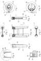
- an inserter 300is configured for use with the fastener 100 of FIGS. 1-9 .
- the inserter 300includes a body 302 having a distal end 304 and a proximal end 306 including a handle portion 308 .
- the bodyincludes a pair of laterally spaced passages extending from the distal end 304 toward the proximal end 306 and each defining a passage axis 307 .
- the passage axes 307are angled 309 to align with the cavities 160 in the fastener 100 .
- Side cuts or windows 310communicate with the passages.
- Each passagereceives a locking bolt 312 in axial sliding and rotating relationship.
- Each bolt 312traverses one of the windows 310 exposing the portion of the bolt 312 within the window for manipulation.
- a knob 314is fixed to each bolt 312 , such as by pinning, to allow a user to rotate the bolt 312 about the passage axis 307 and to serve as a limit to axial travel of the bolt 312 as the knob abuts the proximal or distal margins 316 , 318 of the window 310 .
- Each bolt 312includes a smooth cylindrical portion 320 sized to fit into the trailing portion 162 of the stepped cylindrical cavity 160 in one of the fastener legs.
- Each bolt 312includes a threaded portion 322 , distal to the smooth portion 320 , sized to screw into the threaded leading portion 164 of the stepped cavity 160 .
- the proximal end 306 of the inserter 300includes an engagement portion configured to rotationally couple to a cross fixation guide discussed further below.
- the engagement portionincludes a socket 324 extending distally into a top surface 325 of the handle portion 308 and a peripheral edge 326 .
- the inserter 300is joined to the fastener 100 by first sliding the locking bolts 312 proximally until the knobs 314 abut the proximal margin 316 of the window 310 as shown in FIG. 17 .
- the threaded portion 322may then be inserted into the cavity 160 of the fastener 100 .
- Each knob 314is then rotated to thread the locking bolt 312 into the cavity 160 and secure the fastener 100 to the inserter 300 as shown in FIG. 18 .
- a cross fixation guide 400is engageable with the inserter to guide placement of an elongate member through the aperture 118 of the fastener 100 .
- the elongate membermay be a pin, screw, drill, wire or other member.
- the guide 400may be used to place a guide wire through the aperture and the guide wire may be used to insert a cannulated screw.
- the cross fixation guide 400includes an arcuate guide body 402 having at one end an engagement portion 404 and at an opposite end a guide portion 406 .
- the engagement portion 404is configured to rotationally couple to the inserter 300 . In the illustrative example of FIGS.
- the engagement portion 404includes a stud 407 extending distally from the guide body 402 from a proximal end 408 to a distal end 410 and defining an engagement axis 412 .
- the guide 400includes an axial stop and a rotational stop to aid in positioning the guide 400 relative to the inserter 300 .
- a shoulder 414 formed near the proximal end 408 of the stud 407serves as the axial stop and a side surface 416 transverse to the shoulder 414 and formed on the guide body 402 serves as the rotational stop.
- the guide portion 406defines a cross fixation insertion axis 420 transverse to the engagement axis 412 and along which a fixation member may be guided to pass through the fastener aperture 118 .
- the guide portionincludes a passage through the guide body 402 defining the cross fixation insertion axis 420 and a sleeve 422 received in the passage in axial sliding relationship.
- the sleeve 422includes an axial through passage, proximal handle portion 424 and a distal leading end 426 forming a tapered tip.
- the axial through passageis sized to guide a guide wire along the cross fixation insertion axis 420 .
- the sleevemay be translated along the axis 420 relative to the guide body 402 to position the leading end 426 at a desired spacing from a bone.
- the cross fixation guide 400is coupled to the inserter 300 by inserting the stud 407 into the socket 324 until the shoulder 414 abuts the top surface 325 of the inserter handle 308 as shown in FIG. 20 .
- the cross fixation insertion axis 420is aligned with the center of the fastener aperture 118 .
- the cross fixation guide 400may be rotated relative to the inserter 300 about the engagement axis 412 through an infinite number of angular positions between a first angular position shown in solid line in FIGS.
- a fixation member to be inserted through the fastener aperture 118such as screw 636 in FIG. 36 , has a longitudinal axis and a transverse dimension normal to the longitudinal axis.
- the fixation membermay be inserted through the aperture 118 at an included angle between the longitudinal axis of the fixation member and the aperture length axis ranging from 90 degrees to a value corresponding to a projected length of the aperture along the fixation member longitudinal axis equal to or greater than the fixation member transverse dimension.
- the angular stopslimit the rotation of the guide to be within this range so it is guaranteed that the fixation member will fit through the aperture.
- the first and second angular positionsare limited by abutment of the side surface 416 of the cross fixation guide with the peripheral edge 326 of the inserter 300 .
- FIGS. 23-25depict another illustrative example of a fastener 500 according to one example of the invention in which the rigid body 104 of fastener 100 has been replaced with a flexible member 502 .
- the fastenerincludes first and second legs 504 , 506 .
- the flexible member 502connects to axially spaced first and second connectors on the first leg 504 and passes through a receiver on the second leg 506 in sliding relationship to permit the angle between the fastener legs to be varied between arbitrary angles and to facilitate equal tensioning of the flexible member 502 .
- FIGS. 23-25depict another illustrative example of a fastener 500 according to one example of the invention in which the rigid body 104 of fastener 100 has been replaced with a flexible member 502 .
- the fastenerincludes first and second legs 504 , 506 .
- the flexible member 502connects to axially spaced first and second connectors on the first leg 504 and passes through a receiver on the second leg 506 in sliding
- the flexible member 502is attached at a first location 508 on the first leg 504 , extends to the second leg 506 , passes through a first passage 510 in the second leg, extends axially along a portion of the second leg, passes through a second passage 512 in the second leg, and returns to the first leg 504 where it is attached at a second location 516 .
- the flexible member 502is able to slide freely within the passages 510 , 512 in the second leg to allow the fastener legs 504 , 506 to be variably angled relative to one another and so that tension in the flexible member is distributed equally throughout the flexible member 502 .
- the fastener 500may include a tensioning device operable to shorten the portion of the flexible member 502 that extends outwardly from the first leg 504 .
- the first leg 504includes a tensioning member operable to shorten the flexible member, such as for example by pressing the flexible member into the socket 524 .
- a tensioning screw 520may be engaged with the threaded portion 522 of the socket 524 .
- the flexible member 502is attached to the first leg 504 so that it passes through the threaded portion 522 distal to the tensioning screw 520 .
- Advancing the tensioning screw 520presses the flexible member distally into the socket causing a portion of the flexible member 502 to be pulled into the first leg 504 and thus shortening the portion of the flexible member 502 that extends outwardly from the first leg 504 .
- holesmay be formed in the bone using a hole guide as in the preceding examples.
- the legs 504 , 506may be attached to a driver, for example like that of FIG. 15 , and inserted into the bone holes.
- Tensioning screw 520may then be inserted and advanced to shorten the flexible member and compress the bone.
- FIGS. 26-37illustrate a method of using the fastener and instruments of FIGS. 1-22 .
- first and second bone portions 600 , 602abut at an interface 604 such as a joint articular surface, fracture, osteotomy cut plane, or other interface.
- the hole forming guide 200is positioned over the bone portions with the alignment notches 218 aligned with the interface 604 to center the guide 200 over the interface 604 .
- Fixation pins 606may be placed in holes 220 in the guide 200 to secure the guide 200 to the bone portions.
- a drill 608is guided in the guide holes 208 , 210 to form corresponding holes 610 , 612 in the bone.
- these holespass through the bones so that the legs of the fastener 100 will engage the bone portions bi-cortically at the proximal and distal cortices 607 , 609 .
- a saw blade 614is guided in the saw slot 216 of the guide 200 to form a bone slot 616 to ease insertion of the fastener body through the proximal cortex.
- the saw slotonly extends through the proximal bone cortex since only a proximal slot s needed to insert the fastener body.
- a depth gauge 618is used to probe the bone holes 610 , 612 to determine their depth as an aid in selecting a fastener of the appropriate size to provide bi-cortical fixation.
- the holesmay have different depths and may preferably receive a fastener having different length legs.
- a fastener 100is started into the bone holes 610 , 612 .
- the inserter 300has been omitted from the figures to simplify the drawings.
- the outboard surfaces 148 , 150 of the fastener legsare sized to match the proximal spacing of the outboard bone hole walls. Since outboard surfaces 148 , 150 are parallel, they stay in contact with the proximal portion of the bone holes 610 , 612 as the fastener is advanced into the bone portions.
- Inboard gaps 620 , 622are present between the fastener legs and the bone holes.
- Outboard gaps 624 , 626occur between the fastener legs and the bone holes distal of the proximal edge of the bone holes as the fastener is advanced.
- the inboard gaps 620 , 622diminish as the fastener is advanced until at some point in the fastener's travel, the fastener leg inboard surfaces 128 , 130 contact the inboard bone hole walls. Since the inboard surfaces 128 , 130 diverge at the same angle as the bone holes 610 , 612 , the fastener leg inboard surfaces 128 , 130 contact the bone all along the length of the portions of the legs that have been inserted. Further advancing the fastener will compress the bone between the fastener legs uniformly along the fastener legs proximally to distally.
- the boneis compressed between the fastener legs normal to the insertion direction the same amount at every point along the fastener legs proximally to distally.
- the bone portionswill be compressed axially relative to the longitudinal axis 628 .
- the amount of compressioncan be tailored by setting the spacing of the inboard surfaces of the bone holes 610 , 612 relative to the fastener leg inboard surfaces 128 , 130 . With the inboard bone hole surfaces further apart, the inboard fastener surfaces will contact the bone holes earlier in the fastener's travel and further advancing the fastener to a final resting position will cause relatively more compression.
- the fastener 100is seated with the trailing ends of the fastener legs flush with or below the bone surface to reduce irritation of surrounding tissues.
- the fastener 100is seated with the trailing end 108 of the body below flush and more preferably below the proximal cortex 607 to allow for cortical healing above the fastener body 104 .
- To remove the fastenerit is pulled proximally.
- the sharpened trailing edge of the body 104aids in passing the body through any bone that has grown over the body 104 .
- the leading end 106 of the bodystays inside the bone and more preferably the leading end 106 is above the distal cortex 609 to preserve bone strength.
- the cross fixation guide 400is mounted to the inserter 300 which is attached to the fastener 100 .
- the cross fixation guide 400is pivoted relative to the inserter 300 to direct the cross fixation axis 420 in a desired direction. For example, it may be pivoted to align with a desired entry point on the bone 632 .
- the rotation stopsguarantee that the axis 420 is not angled so acutely as to prevent passage of a fixation member through the fastener aperture 118 .
- the sleeve 422is translated axially to position the sleeve close to the bone entry point 632 to stabilize a guide wire 634 as it is inserted through the sleeve, into the bone, and through the aperture 118 .
- a fixation screw 636is advanced over the guide wire 634 into the bone and through the aperture 118 .
- the guide wire 634is then removed.
- the screw 636is sized and positioned for bi-cortical fixation.
- the screwpasses through both bone portions to further stabilize the interface 604 .
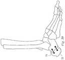
- the implants, instruments and methods of examples of the inventionmay be used at many different locations within a patient to secure bone portions relative to one another and may further be used to form various constructs as shown in the illustrative examples of FIGS. 38-44 . While illustrative, these examples are not comprehensive and it will be apparent to one skilled in the art that these implants, instruments, and methods may be used anywhere two bone portions are to be secured. The size and proportion of the fastener may be varied to suit a particular anatomical location.
- a human footillustrates various examples of applications for the invention.
- a phalangeal fusionis indicated at 700 .
- a metatarsophalangeal fusionis indicated at 702 .
- a fusion of a midshaft fracture or osteotomyis indicated at 704 .
- Metatarsocuneiform fusionsare indicated at 706 and 708 .
- joining elements 710 , 712have been attached between separate fasteners to form a construct in a lisfranc procedure.
- the joining elements 710 , 712may be attached with screws threaded into the sockets in the proximal ends of the fastener legs.
- the joining elements 710 , 712may be rigid or flexible depending on the amount of constraint desired.
- Tarsal fusionsare indicated at 714 and 716 .
- a calcaneal osteotomyhas been fixed using fasteners according to one example of the invention at 718 and 720 .
- applications in the human handare illustrated similar to those shown for the foot.
- thesemay include phalangeal fusion 750 , metacarpophalangeal fusion 752 and 754 , midshaft fusion 756 , metacarpocarpal fusion 758 , and carpal fusion 760 .
- a closing wedge tibial osteotomyis illustrated in which the closed wedge is fixed with one or more of an anteriorly 762 and/or laterally 764 placed fastener according to one example of the invention.
- an opening wedge tibial osteotomyis illustrated in which a graft is fixed into the opened wedge with one or more of an anteriorly 766 and/or medially 768 placed fastener according to one example of the invention.
- the medial fastener 768is proportioned so that the fastener legs are inserted into tibial bone on either side of the graft.
- a spacersuch as an articulating surface or fusion implant to a bone.
- a spacersuch as an articulating surface or fusion implant
- Such joint replacement proceduresmay replace for example a discrete diseased portion of the joint as in a resurfacing procedure or in a uni-compartmental arthroplasty procedure.
- Joint replacement proceduresmay replace the entire articulating surface of one bone of a joint leaving the other bone, or bones, in their natural state such as for example in a hemi-arthroplasty procedure.
- Joint replacement proceduresmay replace all of the articulating surfaces at a joint as in, for example, a total joint arthroplasty.
- the implants utilizedinclude a spacer having a base plate and/or a stem to anchor the implant to the underlying bone and may include surfaces for cementitious or osseous integration for enhanced fixation.
- Joint arthroplastyhas been proposed for use at the shoulder, elbow, wrist, hand, and finger joints of the upper extremity. It has likewise been proposed for use at the hip, knee, ankle, foot, and toe joints of the lower extremity.
- Joint arthroplastyhas been proposed for use between adjacent vertebrae of the spine.
- Joint implantsmay include articulating spacers to facilitate motion between bones or they may include stationary spacers intended to cause joint fusion with a desired bone spacing.
- FIGS. 45-50illustrate an example of an implant 800 for resurfacing at least a portion of an articulating end of a bone adjacent a skeletal joint in one example of the invention.
- the form of the articular surface of the implantmay take any form suitable for a particular joint in the body.
- features of the implant inserted into opposing bone portionscause compression of one bone portion against another bone portion.
- features of the implantcause compression of a portion of the implant against an external surface of a bone such as a natural or prepared surface. For example, a first portion of the implant contacts an external surface of the bone and a second portion of the implant is inserted into the bone to cause compression of the first portion of the implant against the external surface of the bone.
- FIGS. 45-50illustrate an implant 800 in the form of a tibial prosthesis that provides an articular surface on the proximal end of a tibia after it has been prepared by removing the natural articular surface to create a planar surface.
- the implant 800includes a spacer or articular portion that is positioned on a surface of a prepared tibia and an anchor portion including a leg that is inserted into the tibial bone.
- the implantincludes an insertion axis 802 extending between a leading end 804 and a trailing end 806 .
- the articular portioncomprises a separate bearing component 810 and a tray component 812 removably joined together.
- the bearing component and tray componentmay be a single unitary construct.
- the bearing component 810has an upper bearing surface 814 for articulation with an opposing bone or implant component (not shown).
- the tray component 812has a lower bone engaging surface 816 that rests on the surface of the prepared tibia.
- the lower surface 816is planar and parallel to the insertion axis.
- the lower face 816may include various bone ingrowth or cement bonding features as are known in the art.
- the lower surface 816may include roughened textures, spikes, tabs, posts, and/or other features for immediate mechanical engagement of the bone surface.
- a leg 822is joined to the lower bone engaging surface of the spacer for insertion into the tibia.
- the legis joined to the spacer by way of an intermediate body 820 .
- the anchor portionincludes the body 820 joined to and extending from the lower surface 816 and the leg 822 joined to the distal end of the body 820 .
- the body 820 and leg 822are configured generally as shown and described relative to the example of FIGS. 1A-9 with the second leg of FIGS. 1A-9 being replaced by the spacer. As with the example of FIGS.
- the inboard surface 824 of the legfaces the insertion axis 802 and extends from a leading end 836 to a trailing end 838 and the inboard surface 824 is spaced from the lower surface 816 a leading distance 840 near the leading end and a trailing distance 842 near the trailing end.
- the leading distance 840is greater than the trailing distance 842 so that the lower face 816 and inboard surface 824 diverge in the leading direction defined by the leading end.
- the legmay be removably attached to the spacer.
- the legmay be provided as a plurality of legs, the plurality of legs being interchangeable mountable relative to the spacer to provide a selectable size or shape of first leg.
- the legmay be engaged in sliding relationship to facilitate independent positioning of the articular component on the bone and adjusting of the compression created by the anchor component.
- the leg 822may include a lengthwise slot 846 able to receive an enlarged edge 848 of the body. The leg 822 may slide lengthwise relative to the body but is prevented from moving distally away from the body 820 while the enlarged edge 848 is engaged with the slot 846 .
- the enlarged edgemay take any form known in the art for producing a mechanism that slides in one direction but is constrained in a transverse direction. Examples may include but are not limited to a dovetail, spline, key hole, key and keyway, or other form.
- the slot 846may extend the full length of the leg 822 or only partway.
- the leg 822may be trapped on the body 820 or it may be removable and replaceable in one or both of the leading direction or trailing direction. In the example of FIGS. 45-50 , the leg 822 is slotted from the trailing end 838 partway toward the leading end 836 . The leg 822 may be removed from the body by sliding it in the leading direction as seen in FIG. 48 .
- FIG. 49The position of the leg 822 shown in FIG. 49 is the initial insertion position.
- FIG. 50illustrates the leg having been driven forward to a subsequent position that will increase the compression of the lower surface 816 against the bone.
- FIGS. 51 and 52illustrate a hole forming guide 850 having a guide body 851 .
- the guideis similar to that of FIGS. 10-14 including holes 852 having axes 854 for guiding a punch, drill or the like to form a bone hole for receiving the leg 822 and slots 856 for guiding a saw, chisel, or the like to form a bone slot for receiving the body 820 .
- the guide 850includes a probe 858 having a probe lower surface 860 engageable with the bone surface on which the tray lower surface 816 will rest to orient the holes 852 and slots 856 relative to the bone surface.
- FIGS. 10-14illustrate a hole forming guide 850 having a guide body 851 .
- the guideis similar to that of FIGS. 10-14 including holes 852 having axes 854 for guiding a punch, drill or the like to form a bone hole for receiving the leg 822 and slots 856 for guiding a saw, chisel, or the like to form a
- the hole axes 854diverge from the probe lower surface 860 at an angle equal to the divergence of the tray lower surface 816 and leg inboard surface 824 .
- the equal divergence of the hole and legresults in uniform compression over the length of the leg.
- the guide 850is positioned with the probe lower surface 860 resting on the planar cut surface 870 of the tibia 872 and the guide body 851 abutting the anterior of the tibia as shown in FIG. 52 .
- a drill 874for example, is guided in the guide hole 852 to form a bone hole 876 .
- a saw(not shown), for example, is guided in the slot 856 to form a bone slot 878 intersecting the bone hole 876 and the cut surface 870 of the tibia.
- the guide 850is removed. Referring to FIG.
- the implant 800is pressed in the leading direction with the lower surface of the tray 816 in contact with the cut surface 870 , the body 820 in the slot 878 , and the leg 822 in the bone hole 876 .
- the legwill engage the wall of the bone hole as described relative to the example of FIGS. 1A-9 .
- the implant tray 812may be positioned at a desired location on the tibia and the leg 822 then driven to compress the tray 812 against the bone.
- the lower bone engaging surfacemay first be engaged with the bone in a first direction transverse to the surface and then, without shifting the bone engaging surface across the bone, the leg may be advanced in a second direction transverse to the first direction to compress the bone engaging surface against the bone.
- a crossing screwmay be placed through the optional aperture 880 if desired as described relative to the example of FIGS. 1A-9 such as by using the cross fixation guide 400 of FIG. 19 .
- the optionally separate sliding legmay be positioned as shown in FIG. 49 , with the leading end of the body 820 abutting the leading end 847 of the slot 846 . As the implant is driven forward, e.g.
- a drivermay be engaged with the trailing end of the leg 822 to drive the leg to compress the implant against the bone.
- a removal toole.g. a slap hammer, may be engaged with the trailing end of the leg 822 and the leg withdrawn to reduce the compression and allow the implant to be removed.
- a driver or removal toolmay engage the leg 822 via a threaded socket such as that shown in FIG. 9 .
- FIG. 54illustrates another example of an implant 900 similar to that of FIGS. 1A-9 .
- the body 902includes a spacer 904 that may be placed between bone portions to maintain them a desired distance apart and anchor portions, as described relative to the example of FIGS. 45-50 , positioned on opposite sides of the spacer 904 .
- the implant 900 of FIG. 54is suitable, for example, for spacing and securing adjacent bone portions while they fuse together during healing. Examples of applications for such an implant include fusing adjacent vertebrae of the spine, joint fusions at other locations, osteotomy fusions, and the like where it is desired to fill a natural or surgically created gap between the bone portions.
- the spacer 904may have planar, parallel opposing sides as shown or they may be shaped to fit the contours of the adjacent bone and/or to fill an angled gap.
- the legs 906include a through hole 908 that may receive a screw 910 axially.
- a screw 910axially.
- only one screwis shown but one may be provided in both legs or not at all.
- the screwhas a trailing head 912 and a leading thread 914 . When the screw 910 is rotated, the threads engage the wall of the bone hole and the head abuts the trailing end of the leg to pull the leg 906 and thus the implant 900 forward into engagement with the bone.
- the screw 910allows the implant 900 to be driven smoothly without impact forces.
- the screwalso prevents the implant 900 from translating backward.
- the screwmay be permanently trapped within the implant or it may be removably engaged.
- the leg 906may have a longitudinal slot through which the screw may be moved laterally to be engaged with or disengaged from the leg 906 .
- FIG. 55illustrates a hole forming guide 950 similar to that of FIGS. 10-14 but having an additional probe 952 with a thickness equal to that of the spacer 904 and which is inserted between the bone portions to position them in the proper orientation relative to the guide 950 .
- FIGS. 56 and 57illustrate an interbody fusion procedure using the guide 950 and implant 900 .
- the guideis positioned with the probe 952 between the vertebrae 956 , 958 and a hole 962 is formed in each bone portion.
- the guide 950is removed and the implant 900 is inserted so that each bone portion is compressed against one of the opposing sides of the spacer 904 .
- the independently sliding leg shown in the example of FIG. 45-50may be used with the example of FIGS. 1A-9 or the example of FIG. 54 .
- the longitudinal screw of FIG. 54may be used with the example of FIGS. 1A-9 or the example of FIG. 45-50 .
- the threaded inserter 300 of FIGS. 15-18 , the cross fixation guide 400 of FIG. 19 , or the flexible member 502 of FIGS. 23-25may be used with the example of FIGS. 45-50 or the example of FIG. 54 .
- FIG. 58depicts a fastener 1000 in the form of a staple similar to the fastener in the example of FIGS. 1A-9 .
- the inboard surfaces 1002 and 1004 of the legsare parallel.
- the leading end of each legincludes a relieved portion 1006 , 1008 on the inboard side.
- the relieved portionmay be in the form of a flat or radiused surface and serves to create compression as the fastener 1000 is inserted into holes formed in bone.
- the legseach have a length 1010 measured parallel to the insertion axis 1012 .
- the relieved portionseach have a length 1014 measured parallel to the insertion axis 1012 .
- the relieved portion length 1014is preferably greater than 5% of the leg length 1010 . More preferably the relieved portion length is in the range from 5% to 50% of the leg length. More preferably the relieved portion length is in the range from 10% to 30% of the leg length. More preferably the relieved portion length is in the range from 10% to 20% of the leg length.
- the relieved portionsprovide divergent ramps.
- the outer surfaces 1020 , 1022are parallel.
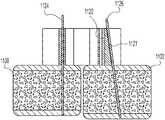
- FIGS. 59-61illustrate an example of a method of using the fastener 1000 of FIG. 58 .
- bone holes 1024 , 1026have been formed at least partway through first and second bone portions 1028 , 1030 .
- the bone holesmay be formed with a guide similar to the guide 200 of FIG. 26 but having parallel rather than divergent guide holes.
- the guidemay also be used to guide the formation of a slot in the bone extending between the bone holes.
- the bone holeshave inboard surfaces 1032 , 1034 .
- the bone hole inboard surfacesare spaced apart a distance X 1036 .
- the inboard surfaces of the fastener legsare spaced apart a distance Y 1038 .
- the bone holes 1024 , 1026are offset outwardly to create interference with the inboard surfaces of the legs, or in other words, X is greater than Y.
- the holesare sized so that the outer surfaces 1020 , 1022 of the legs can slide freely within the holes.
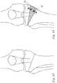
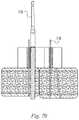
- FIGS. 62-72illustrate an example of a method in which instruments are used to compress first and second bone portions 1100 , 1102 together prior to insertion of a staple with parallel legs.
- a guide 1104has been positioned on the first and second bone portions.
- the guide 1104 of FIG. 62is similar to the guide 200 of FIG. 26 .
- the guide 1104 of FIG. 62has parallel guide holes 1106 , 1108 .
- Fixation holes 1110 , 1112 formed through the guideare sized to receive fixation pins to secure the guide to bone.
- Slots 1114 , 1116 formed collinear with the holes 1106 , 1108 , 1110 , 1112are also sized to receive fixation pins.
- a removable angle guide 1120 with a handle 1122may be positioned within one of the slots 1114 , 1116 .
- the angle guide 1120has a generally wedge-shaped body as shown in FIG. 63 providing a guide surface 1121 that diverges outwardly from the fixation holes 1110 , 1112 in the direction toward the bone surface.
- first and second bone portionshave been aligned approximately in a desired orientation.
- a first fixation pin 1124has been inserted into a fixation hole 1110 and into the first bone portion 1100 .
- a second fixation pin 1126has been inserted into a slot 1116 and into the second bone portion 1102 by guiding the second fixation pin 1126 along the angle guide 1120 to place the second fixation pin 1126 non-parallel to the first fixation pin 1124 with the pins diverging from one another in a direction into the bone.
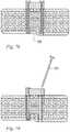
- the bone portions 1102 , 1104have been rotated relative to one another to position the fixation pins parallel to one another.
- the angle guide 1120has been removed from the slot 1116 .
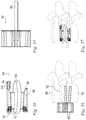
- a compressor 1130is engaged with the fixation pins.
- the compressoris engaged by sliding bushings 1132 , 1134 on the end of compressor arms over the ends of the fixation pins.
- the compressoris then actuated to move the fixation pins, and consequently the first and second bone portions, toward one another.
- FIG. 67when the compressor is actuated to move the bone portions together, one aspect of the bone portions will contact first due to the relative angle between the pins during insertion and the subsequent rotation of the bone portions to align the pins.
- the lower edges of the bone portionswill contact first. With further compression, the bone portions will rotate into contact with one another at multiple points along the interface between the bone portions to a reduced position. The relative rotation between the bone portions causes one or both of the fixation pins to elastically deform in bending. With one of the pins in the slot 1116 , the pin is allowed to translate within the slot as the pins move together.
- the bone portionshave been moved together until they contact all along the bone interface. With the top edges of the bone portions in contact, the elasticity of the fixation pins imparts oppositely directed moments on the bone portions to ensure that the lower edges of the bone portions remain biased together.
- a third fixation pin 1136has been inserted into the second fixation hole 1112 in the guide to secure the bones in the reduced position and the second fixation pin 1126 has been removed.
- a drill 1138is shown being guided by the guide holes 1106 , 1108 to form bone holes.
- a saw blade 1140is guided by the guide to form a slot extending between the bone holes to receive the fastener body.
- a parallel legged fastener 1142similar to that of FIG. 58 is inserted with a leg in each of the bone holes to secure the bones relative to one another. Because the legs are parallel, the fastener 1142 may be inserted through the guide. Alternatively, the guide may be removed before the staple is inserted. The guide may include removable inserts that may be inserted into the guide to provide guide surface for the drill and saw blade and then removed to provide clearance for inserting the staple through the guide.
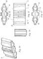
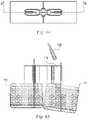
- FIG. 73illustrates an example of a fastener 1200 having parallel legs as in the example of FIG. 58 .
- the fastener 1200is formed of an elastic aterial so that it may be elastically deformed in a direction normal to the insertion axis 1202 .
- the deformed configurationis shown in dashed lines and the relaxed state is shown in solid lines.
- FIG. 74illustrates another example of a fastener 1250 similar to the fastener 1200 of FIG. 73 .
- Fastener 1250 of FIG. 74differs from the fastener 1200 in that rather than having an implant body in the form of a web extending between the legs, the fastener 1250 has discrete bands 1252 , 1254 of material extending between the legs.
- the fasteners 1200 , 1250may be made from any material having a suitable elastic deformation range.
- the fasteners 1200 , 1250are made from a superelastic material.
- An example of a suitable superelastic metallic materialis superelastic nitinol.
- the fastenersare elastically deformed by displacing the legs outwardly normal to their insertion axes and held in the deformed state while they are inserted. After insertion, into the bone portions, the legs are released and the legs move back toward their relaxed state compressing the bone portions between them.
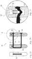
- FIGS. 75-77illustrate an example of an inserter 1270 for use with the fasteners of FIGS. 73 and 74 .
- the inserter 1270includes a handle 1272 and a head 1274 .
- the headincludes spaced apart holes that receive rigid pins 1276 extending from the head.
- a fasteneris deformed by pulling the legs away from one another and sliding the rigid pins into the legs to keep them separated.
- a fasteneris provided pre-mounted on the inserter 1270 .
- one of the pinshas been withdrawn from the inserter to allow the fastener to return toward its relaxed state and compress the bone portions together.
- FIGS. 58-79may be substituted or combined with features of the examples of FIGS. 1-57 to form additional examples within the scope of the invention.
- the examples of FIGS. 58-79may be used to treat various conditions of the feet, hands, knees, spine and other locations as shown and described relative to the examples of FIGS. 1-57 .
- the examples of FIGS. 58-79may be combined with the examples of FIGS.
Landscapes
- Health & Medical Sciences (AREA)
- Orthopedic Medicine & Surgery (AREA)
- Life Sciences & Earth Sciences (AREA)
- Surgery (AREA)
- Engineering & Computer Science (AREA)
- Biomedical Technology (AREA)
- General Health & Medical Sciences (AREA)
- Heart & Thoracic Surgery (AREA)
- Animal Behavior & Ethology (AREA)
- Public Health (AREA)
- Veterinary Medicine (AREA)
- Neurology (AREA)
- Medical Informatics (AREA)
- Molecular Biology (AREA)
- Nuclear Medicine, Radiotherapy & Molecular Imaging (AREA)
- Oral & Maxillofacial Surgery (AREA)
- Vascular Medicine (AREA)
- Cardiology (AREA)
- Transplantation (AREA)
- Physical Education & Sports Medicine (AREA)
- Dentistry (AREA)
- Surgical Instruments (AREA)
- Prostheses (AREA)
- Rheumatology (AREA)
Abstract
Description
Claims (20)
Priority Applications (3)
| Application Number | Priority Date | Filing Date | Title |
|---|---|---|---|
| US15/912,346US10743995B2 (en) | 2015-07-02 | 2018-03-05 | Orthopedic fasterners, instruments and methods |
| US16/930,264US20200337845A1 (en) | 2015-07-02 | 2020-07-15 | Orthopedic fasteners, instruments and methods |
| US18/045,841US20230111234A1 (en) | 2015-07-02 | 2022-10-12 | Orthopedic fasteners, instruments and methods |
Applications Claiming Priority (5)
| Application Number | Priority Date | Filing Date | Title |
|---|---|---|---|
| US201562188185P | 2015-07-02 | 2015-07-02 | |
| US201662308011P | 2016-03-14 | 2016-03-14 | |
| US15/194,108US20170000533A1 (en) | 2015-07-02 | 2016-06-27 | Compression implants, instruments and methods |
| US201762465289P | 2017-03-01 | 2017-03-01 | |
| US15/912,346US10743995B2 (en) | 2015-07-02 | 2018-03-05 | Orthopedic fasterners, instruments and methods |
Related Parent Applications (2)
| Application Number | Title | Priority Date | Filing Date |
|---|---|---|---|
| US15/194,108Continuation-In-PartUS20170000533A1 (en) | 2015-07-02 | 2016-06-27 | Compression implants, instruments and methods |
| US15/194,108ContinuationUS20170000533A1 (en) | 2015-07-02 | 2016-06-27 | Compression implants, instruments and methods |
Related Child Applications (1)
| Application Number | Title | Priority Date | Filing Date |
|---|---|---|---|
| US16/930,264ContinuationUS20200337845A1 (en) | 2015-07-02 | 2020-07-15 | Orthopedic fasteners, instruments and methods |
Publications (2)
| Publication Number | Publication Date |
|---|---|
| US20180193151A1 US20180193151A1 (en) | 2018-07-12 |
| US10743995B2true US10743995B2 (en) | 2020-08-18 |
Family
ID=57609062
Family Applications (5)
| Application Number | Title | Priority Date | Filing Date |
|---|---|---|---|
| US15/194,016Active2037-05-07US10376367B2 (en) | 2015-07-02 | 2016-06-27 | Orthopedic fasteners, instruments and methods |
| US15/194,108AbandonedUS20170000533A1 (en) | 2015-07-02 | 2016-06-27 | Compression implants, instruments and methods |
| US15/912,346Active2037-02-02US10743995B2 (en) | 2015-07-02 | 2018-03-05 | Orthopedic fasterners, instruments and methods |
| US16/930,264AbandonedUS20200337845A1 (en) | 2015-07-02 | 2020-07-15 | Orthopedic fasteners, instruments and methods |
| US18/045,841AbandonedUS20230111234A1 (en) | 2015-07-02 | 2022-10-12 | Orthopedic fasteners, instruments and methods |
Family Applications Before (2)
| Application Number | Title | Priority Date | Filing Date |
|---|---|---|---|
| US15/194,016Active2037-05-07US10376367B2 (en) | 2015-07-02 | 2016-06-27 | Orthopedic fasteners, instruments and methods |
| US15/194,108AbandonedUS20170000533A1 (en) | 2015-07-02 | 2016-06-27 | Compression implants, instruments and methods |
Family Applications After (2)
| Application Number | Title | Priority Date | Filing Date |
|---|---|---|---|
| US16/930,264AbandonedUS20200337845A1 (en) | 2015-07-02 | 2020-07-15 | Orthopedic fasteners, instruments and methods |
| US18/045,841AbandonedUS20230111234A1 (en) | 2015-07-02 | 2022-10-12 | Orthopedic fasteners, instruments and methods |
Country Status (5)
| Country | Link |
|---|---|
| US (5) | US10376367B2 (en) |
| EP (1) | EP3316824A4 (en) |
| AU (1) | AU2016287484B2 (en) |
| CA (1) | CA2990637C (en) |
| WO (1) | WO2017004221A1 (en) |
Cited By (18)
| Publication number | Priority date | Publication date | Assignee | Title |
|---|---|---|---|---|
| US11071573B2 (en) | 2014-09-18 | 2021-07-27 | Si-Bone Inc. | Matrix implant |
| US11116519B2 (en) | 2017-09-26 | 2021-09-14 | Si-Bone Inc. | Systems and methods for decorticating the sacroiliac joint |
| US11147688B2 (en) | 2013-10-15 | 2021-10-19 | Si-Bone Inc. | Implant placement |
| US11234830B2 (en) | 2019-02-14 | 2022-02-01 | Si-Bone Inc. | Implants for spinal fixation and or fusion |
| US11304705B2 (en) | 2015-02-19 | 2022-04-19 | Crossroads Extremity Systems, Llc | Indexed tri-planar osteotomy guide and method |
| US11304735B2 (en) | 2020-02-19 | 2022-04-19 | Crossroads Extremity Systems, Llc | Systems and methods for Lapidus repair of bunions |
| US11369419B2 (en) | 2019-02-14 | 2022-06-28 | Si-Bone Inc. | Implants for spinal fixation and or fusion |
| US11471286B2 (en) | 2012-03-09 | 2022-10-18 | Si-Bone Inc. | Systems, devices, and methods for joint fusion |
| US11547425B1 (en) | 2022-05-19 | 2023-01-10 | Gramercy Extremity Orthopedics Llc | Tarsometatarsal joint arthrodesis tools and related method for bunion correction |
| US11571245B2 (en) | 2019-11-27 | 2023-02-07 | Si-Bone Inc. | Bone stabilizing implants and methods of placement across SI joints |
| US11633292B2 (en) | 2005-05-24 | 2023-04-25 | Si-Bone Inc. | Apparatus, systems, and methods for the fixation or fusion of bone |
| US11684378B2 (en) | 2014-09-18 | 2023-06-27 | Si-Bone Inc. | Implants for bone fixation or fusion |
| US11752011B2 (en) | 2020-12-09 | 2023-09-12 | Si-Bone Inc. | Sacro-iliac joint stabilizing implants and methods of implantation |
| US12083026B2 (en) | 2019-12-09 | 2024-09-10 | Si-Bone Inc. | Sacro-iliac joint stabilizing implants and methods of implantation |
| US12403012B2 (en) | 2019-07-26 | 2025-09-02 | Crossroads Extremity Systems, Llc | Bone repositioning guide system and procedure |
| US12419668B2 (en) | 2019-11-21 | 2025-09-23 | Si-Bone Inc. | Rod coupling assemblies for bone stabilization constructs |
| US12427028B2 (en) | 2018-03-28 | 2025-09-30 | Si-Bone Inc. | Threaded implants and methods of use across bone segments |
| US12433733B2 (en) | 2023-08-15 | 2025-10-07 | Si-Bone Inc. | Pelvic stabilization implants, methods of use and manufacture |
Families Citing this family (37)
| Publication number | Priority date | Publication date | Assignee | Title |
|---|---|---|---|---|
| US12409039B2 (en)* | 2010-07-27 | 2025-09-09 | Tenon Medical, Inc. | Systems for sacroiliac joint stabilization |
| EP4252686A3 (en) | 2012-12-28 | 2023-12-27 | Paragon 28, Inc. | Alignment guide apparatus |
| AU2014365821B2 (en) | 2013-12-20 | 2019-10-03 | Crossroads Extremity Systems, Llc | Polyaxial locking hole |
| US11202626B2 (en) | 2014-07-10 | 2021-12-21 | Crossroads Extremity Systems, Llc | Bone implant with means for multi directional force and means of insertion |
| JP2017529886A (en) | 2014-07-10 | 2017-10-12 | クロスローズ エクストリミティ システムズ リミテッド ライアビリティ カンパニー | Bone implant and means of insertion |
| US10653467B2 (en)* | 2015-05-06 | 2020-05-19 | Treace Medical Concepts, Inc. | Intra-osseous plate system and method |
| US10376367B2 (en)* | 2015-07-02 | 2019-08-13 | First Ray, LLC | Orthopedic fasteners, instruments and methods |
| EP3528716B1 (en) | 2016-10-24 | 2024-02-14 | Paragon 28, Inc. | Osteotomy systems |
| US11864753B2 (en) | 2017-02-06 | 2024-01-09 | Crossroads Extremity Systems, Llc | Implant inserter |
| EP3579762B1 (en)* | 2017-02-07 | 2024-06-26 | Crossroads Extremity Systems, LLC | Counter-torque implant |
| EP3585287B1 (en) | 2017-02-27 | 2024-11-13 | Paragon 28, Inc. | Intramedullary nail fixation systems |
| ES2993743T3 (en) | 2017-02-27 | 2025-01-08 | Paragon 28 Inc | Targeting instruments and systems |
| US10918431B2 (en) | 2017-03-30 | 2021-02-16 | Paragon 28, Inc. | Bone fixation system, assembly, implants, devices, alignment guides, and methods of use |
| EP3651699B1 (en) | 2017-07-11 | 2025-09-17 | Paragon 28, Inc. | Bone fixation system, assembly, implants, devices and insertion guides |
| USD870284S1 (en) | 2017-07-31 | 2019-12-17 | Crossroads Extremity Systems, Llc | Osteosynthesis clip |
| BR112019021679A2 (en)* | 2017-08-04 | 2020-05-12 | Wright Medical Technology, Inc. | SCREW DIRECTION GUIDE SYSTEM AND METHOD |
| EP3530224A1 (en)* | 2018-02-23 | 2019-08-28 | Medartis Holding AG | Wrist arthrodesis plate |
| EP3773261A4 (en)* | 2018-04-04 | 2022-05-11 | Wright Medical Technology, Inc. | SYSTEM AND PROCEDURE FOR MINIMALLY INVASIVE MOVEMENT OSTEOTOMY |
| EP3820382B1 (en)* | 2018-07-11 | 2025-09-10 | Paragon 28, Inc. | Systems comprising alignment guides and implants |
| US12295628B2 (en) | 2018-11-01 | 2025-05-13 | Howmedica Osteonics Corp. | Device for fixating orthopedic injury |
| EP3923842A4 (en) | 2019-02-13 | 2022-11-23 | Paragon 28, Inc. | IMPLANTS, ALIGNMENT GUIDES, SYSTEMS AND METHODS OF USE |
| JP7562547B2 (en) | 2019-02-14 | 2024-10-07 | パラゴン28・インコーポレイテッド | Threaded targeting instruments, systems, and methods of use |
| AU2020228309B2 (en) | 2019-02-28 | 2025-10-02 | Paragon 28, Inc. | Fusion systems, instruments, bone plates and methods of use |
| US12059183B2 (en) | 2020-07-31 | 2024-08-13 | Crossroads Extremity Systems, Llc | Bone plates with dynamic elements and screws |
| USD961081S1 (en) | 2020-11-18 | 2022-08-16 | Crossroads Extremity Systems, Llc | Orthopedic implant |
| WO2023047330A1 (en)* | 2021-09-22 | 2023-03-30 | Crossroads Extremity Systems, Llc | Systems and methods for bone fixation |
| WO2023064785A1 (en)* | 2021-10-12 | 2023-04-20 | Lee Randall F | System and method for a medical implant with integrated propulsors |
| US12035928B2 (en)* | 2021-11-12 | 2024-07-16 | NextWave Medical, LLC | Devices and methods for correction of hip deformities |
| US20230181184A1 (en)* | 2021-12-10 | 2023-06-15 | Wright Medical Technology, Inc. | Stabilization devices |
| US20230225868A1 (en)* | 2022-01-15 | 2023-07-20 | Nextremity Solutions, Inc. | Orthopedic fasteners, instruments, and methods |
| US20230310047A1 (en)* | 2022-03-31 | 2023-10-05 | Medartis Ag | Bone wedge implant and method |
| AU2023242748A1 (en)* | 2022-04-01 | 2024-10-17 | Djit Medtech, Inc. | Stemless semi-constrained implantable joint replacement device |
| US20240216024A1 (en)* | 2022-12-30 | 2024-07-04 | Medartis Ag | Orthopedic fasteners, instruments and methods |
| US20240293118A1 (en)* | 2023-03-02 | 2024-09-05 | Medartis Ag | Compression fastener, instruments and methods |
| CN116650085A (en)* | 2023-06-09 | 2023-08-29 | 梅海波 | Memory alloy epiphysis pulls eight characters nail and appurtenance |
| US12290445B1 (en) | 2024-05-03 | 2025-05-06 | Djit Medtech, Inc. | Joint implants with bone interface connectors |
| US12427023B1 (en) | 2024-09-05 | 2025-09-30 | Djit Medtech, Inc. | Joint implants with interface surfaces having registration features |
Citations (14)
| Publication number | Priority date | Publication date | Assignee | Title |
|---|---|---|---|---|
| US4929247A (en)* | 1988-10-06 | 1990-05-29 | Rayhack John M | Bone compression and distraction device |
| US5540695A (en)* | 1994-02-18 | 1996-07-30 | Howmedica Inc. | Osteotomy cutting guide |
| US5951557A (en)* | 1997-12-30 | 1999-09-14 | Luter; Dennis W. | Bone plate |
| WO2000064360A2 (en) | 1999-04-23 | 2000-11-02 | Sdgi Holdings, Inc. | Method for the correction of spinal deformities through vertebral body tethering without fusion |
| US20050277941A1 (en)* | 2004-05-27 | 2005-12-15 | Trumble Thomas E | Method and device for use in osteotomy |
| WO2006122194A1 (en) | 2005-05-11 | 2006-11-16 | Children's Hospital Medical Center | Spinal correction system |
| WO2010028045A1 (en) | 2008-09-02 | 2010-03-11 | Synthes Usa, Llc | Intervertebral implant with blades for connecting to adjacent vertebral bodies |
| US20120253410A1 (en)* | 2011-03-07 | 2012-10-04 | Kyle Taylor | Apparatus and methods for bone repair preparation |
| US20120271314A1 (en)* | 2009-02-24 | 2012-10-25 | Wright Medical Technology, Inc. | Orthopedic surgical guide |
| US20130144343A1 (en) | 2011-11-01 | 2013-06-06 | Imds Corporation | Sacroiliac Fusion Cage |
| US20130150900A1 (en)* | 2011-12-09 | 2013-06-13 | Dr. Steven L. Haddad | Orthopedic plate, orthopedic device, method of coupling bone segments, and method of assembling an orthopedic plate |
| US20130231668A1 (en)* | 2011-08-30 | 2013-09-05 | Russell G. Olsen | Bone treatment system |
| US9113969B2 (en)* | 2010-04-27 | 2015-08-25 | DePuy Synthes Products, Inc. | Bone fixation systems and methods of use |
| US20170000533A1 (en)* | 2015-07-02 | 2017-01-05 | First Ray, LLC | Compression implants, instruments and methods |
Family Cites Families (249)
| Publication number | Priority date | Publication date | Assignee | Title |
|---|---|---|---|---|
| FR376911A (en) | 1907-04-19 | 1907-08-24 | Antoine Depage | Fracture bolts |
| FR551418A (en) | 1921-09-06 | 1923-04-05 | Assembly bolt | |
| US2133859A (en) | 1938-03-31 | 1938-10-18 | Louis J Padula | Bone setting |
| US2489870A (en) | 1946-03-02 | 1949-11-29 | Dzus William | Bone fastening device |
| US2511051A (en) | 1946-06-19 | 1950-06-13 | Dzus William | Fastening device |
| US2485531A (en) | 1948-01-13 | 1949-10-18 | Dzus William | Surgical toggle bolt |
| US2825329A (en) | 1953-02-04 | 1958-03-04 | Orville S Caesar | Internal fixation of fractures |
| US2760488A (en) | 1955-04-20 | 1956-08-28 | Robert B Pierce | Internal bone fixation apparatus |
| US3618447A (en) | 1969-09-15 | 1971-11-09 | Phillips Petroleum Co | Deterioration fasteners |
| US3709218A (en) | 1970-04-24 | 1973-01-09 | W Halloran | Combination intramedullary fixation and external bone compression apparatus |
| US3939828A (en) | 1974-09-09 | 1976-02-24 | Mohr Robert N | Method and clasp for internal osseous fixation |
| GB1551705A (en) | 1975-04-28 | 1979-08-30 | Downs Surgicial Ltd | Surgial implant |
| US4060089A (en) | 1975-09-03 | 1977-11-29 | United States Surgical Corporation | Surgical fastening method and device therefor |
| US4456005A (en) | 1982-09-30 | 1984-06-26 | Lichty Terry K | External compression bone fixation device |
| US4531522A (en)* | 1983-06-20 | 1985-07-30 | Ethicon, Inc. | Two-piece tissue fastener with locking top and method for applying same |
| US4635637A (en) | 1984-03-29 | 1987-01-13 | Schreiber Saul N | Surgical suture |
| US4736746A (en) | 1985-04-11 | 1988-04-12 | Dennison Manufacturing Company | Method of fastening tissues |
| US4696300A (en) | 1985-04-11 | 1987-09-29 | Dennison Manufacturing Company | Fastener for joining materials |
| US4688561A (en) | 1985-09-17 | 1987-08-25 | Reese H William | Bone handling apparatus and method |
| FR2602666B1 (en) | 1986-08-18 | 1991-12-20 | Gauthier Georges | FASTENING CLIP, PARTICULARLY FOR OSTEOSYNTHESIS AND METHOD FOR MANUFACTURING SAME |
| US4841960A (en) | 1987-02-10 | 1989-06-27 | Garner Eric T | Method and apparatus for interosseous bone fixation |
| US4790303A (en)* | 1987-03-11 | 1988-12-13 | Acromed Corporation | Apparatus and method for securing bone graft |
| US4994073A (en) | 1989-02-22 | 1991-02-19 | United States Surgical Corp. | Skin fastener |
| US5053038A (en) | 1989-08-17 | 1991-10-01 | Tenstaple, Inc. | Compression bone staple |
| US5385567A (en) | 1990-09-07 | 1995-01-31 | Goble; E. Marlowe | Sight barrel arthroscopic instrument |
| US5085661A (en) | 1990-10-29 | 1992-02-04 | Gerald Moss | Surgical fastener implantation device |
| DE4106823C1 (en) | 1991-03-04 | 1992-06-25 | Liebscher Kunststofftechnik, 8032 Graefelfing, De | |
| CA2065205C (en) | 1991-04-11 | 2002-12-03 | David T. Green | Reduced mass absorbable surgical fastener and retainer |
| US5269783A (en) | 1991-05-13 | 1993-12-14 | United States Surgical Corporation | Device and method for repairing torn tissue |
| EP0521170B1 (en) | 1991-06-11 | 1994-04-06 | B. Braun Holding AG | Package for suture materials |
| US5250049A (en) | 1992-01-10 | 1993-10-05 | Michael Roger H | Bone and tissue connectors |
| US5226535A (en) | 1992-02-14 | 1993-07-13 | Ethicon, Inc. | Package for endoscopic suture loop and cannula |
| US5236440A (en)* | 1992-04-14 | 1993-08-17 | American Cyanamid Company | Surgical fastener |
| DE4220407C1 (en) | 1992-06-19 | 1993-11-25 | Ethicon Gmbh | Package with surgical suturing equipment - has baseplate with rear supporting strip and front transverse ones all with guide recesses and layers between them separating threads attached to needles |
| CA2100532C (en) | 1992-09-21 | 2004-04-20 | David T. Green | Device for applying a meniscal staple |
| US5350380A (en) | 1993-01-15 | 1994-09-27 | Depuy Inc. | Method for securing a ligament replacement in a bone |
| US5350060A (en) | 1993-01-15 | 1994-09-27 | Ethicon, Inc. | Procedure kit and package |
| US5354300A (en) | 1993-01-15 | 1994-10-11 | Depuy Inc. | Drill guide apparatus for installing a transverse pin |
| US6030162A (en) | 1998-12-18 | 2000-02-29 | Acumed, Inc. | Axial tension screw |
| US5312412A (en) | 1993-02-03 | 1994-05-17 | Whipple Terry L | Fixation alignment guide for surgical use |
| US5330468A (en) | 1993-10-12 | 1994-07-19 | Burkhart Stephen S | Drill guide device for arthroscopic surgery |
| US5383367A (en) | 1993-10-18 | 1995-01-24 | Elsag International N.V. | Dynamic temperature compensation for a pressure cell |
| CA2117967A1 (en) | 1993-10-27 | 1995-04-28 | Thomas W. Sander | Tissue repair device and apparatus and method for fabricating same |
| FR2719211B1 (en) | 1994-04-27 | 1996-07-19 | Mortier Jean Pierre | Equipment for correcting foot deformities. |
| US5601571A (en) | 1994-05-17 | 1997-02-11 | Moss; Gerald | Surgical fastener implantation device |
| US6001101A (en) | 1994-07-05 | 1999-12-14 | Depuy France | Screw device with threaded head for permitting the coaptation of two bone fragments |
| IL111985A (en) | 1994-12-14 | 1999-04-11 | Medical Influence Technologies | Staple and thread assembly particularly for use in power-driven staplers for medical suturing |
| US5569306A (en) | 1995-06-06 | 1996-10-29 | Thal; Raymond | Knotless suture anchor assembly |
| DE29724567U1 (en) | 1996-02-14 | 2003-01-16 | Walter Lorenz Surgical, Inc., Jacksonville, Fla. | Bone fixation device and instrument for inserting the bone fixation device |
| AT937U3 (en) | 1996-03-26 | 1996-12-27 | Stoffella Rudolf Dr | IMPLANT FOR FIXING AN OSTEOTOMY |
| US20050143734A1 (en) | 1996-11-12 | 2005-06-30 | Cachia Victor V. | Bone fixation system with radially extendable anchor |
| US6632224B2 (en) | 1996-11-12 | 2003-10-14 | Triage Medical, Inc. | Bone fixation system |
| US5947999A (en)* | 1996-12-03 | 1999-09-07 | Groiso; Jorge A. | Surgical clip and method |
| US5709708A (en) | 1997-01-31 | 1998-01-20 | Thal; Raymond | Captured-loop knotless suture anchor assembly |
| ES2202575T3 (en) | 1997-02-28 | 2004-04-01 | Synthes Ag Chur | IMPLANT FOR OSTEOSYNTHESIS. |
| US5919194A (en) | 1997-07-21 | 1999-07-06 | Anderson; David L. | Orthopaedic implant |
| US6149669A (en) | 1997-10-30 | 2000-11-21 | Li Medical Technologies, Inc. | Surgical fastener assembly method of use |
| US5954747A (en) | 1997-11-20 | 1999-09-21 | Clark; Ron | Meniscus repair anchor system |
| US5921986A (en) | 1998-02-06 | 1999-07-13 | Bonutti; Peter M. | Bone suture |
| US6302887B1 (en) | 1998-07-20 | 2001-10-16 | Joseph John Spranza | Hardware for high strength fastening of bone |
| AT406011B (en) | 1998-07-30 | 2000-01-25 | Stoffella Rudolf Dr | Implant for fixing two bone fragments to each other |
| US6200330B1 (en) | 1998-11-23 | 2001-03-13 | Theodore V. Benderev | Systems for securing sutures, grafts and soft tissue to bone and periosteum |
| US6306159B1 (en) | 1998-12-23 | 2001-10-23 | Depuy Orthopaedics, Inc. | Meniscal repair device |
| US20030045881A1 (en) | 1998-12-30 | 2003-03-06 | Depuy France | Self-compressing osteosynthesis screw for surgery of small bones |
| US6402766B2 (en) | 1999-07-23 | 2002-06-11 | Ethicon, Inc. | Graft fixation device combination |
| US6423073B2 (en) | 1999-07-23 | 2002-07-23 | Ethicon, Inc. | Instrument for inserting graft fixation device |
| US20020052628A1 (en) | 1999-07-23 | 2002-05-02 | Bowman Steven M. | Graft fixation device and method |
| US6436110B2 (en) | 1999-07-23 | 2002-08-20 | Ethicon, Inc. | Method of securing a graft using a graft fixation device |
| US7214232B2 (en) | 1999-07-23 | 2007-05-08 | Ethicon, Inc. | Graft fixation device |
| US20020095157A1 (en) | 1999-07-23 | 2002-07-18 | Bowman Steven M. | Graft fixation device combination |
| US6179840B1 (en) | 1999-07-23 | 2001-01-30 | Ethicon, Inc. | Graft fixation device and method |
| US6364884B1 (en) | 1999-07-23 | 2002-04-02 | Ethicon, Inc. | Method of securing a graft using a graft fixation device |
| US6447517B1 (en) | 1999-07-23 | 2002-09-10 | Ethicon, Inc. | Instrument for inserting graft fixation device |
| US6497707B1 (en) | 1999-07-23 | 2002-12-24 | Ethicon, Inc. | Graft fixation device combination |
| US6554852B1 (en) | 1999-08-25 | 2003-04-29 | Michael A. Oberlander | Multi-anchor suture |
| US6179839B1 (en) | 1999-09-20 | 2001-01-30 | Kinetikos Medical Incorporated | Bone fusion apparatus and method |
| DE19952359C1 (en) | 1999-10-30 | 2001-03-22 | Aesculap Ag & Co Kg | Surgical connection has coupling element, two placement elements, bone plates, and holders |
| US7153312B1 (en) | 1999-12-02 | 2006-12-26 | Smith & Nephew Inc. | Closure device and method for tissue repair |
| US6277130B1 (en) | 1999-12-14 | 2001-08-21 | John H. Shadduck | Electrical discharge surgical fastener for meniscal repairs |
| US6635073B2 (en) | 2000-05-03 | 2003-10-21 | Peter M. Bonutti | Method of securing body tissue |
| NL1014790C2 (en) | 2000-03-30 | 2001-10-02 | Univ Amsterdam | Connecting body for connecting bone parts. |
| DE10021122C1 (en) | 2000-04-29 | 2001-11-08 | Aesculap Ag & Co Kg | Thread anchor system for connecting tissue parts and instrument for inserting an anchor implant |
| DE60119732T2 (en) | 2000-05-31 | 2007-02-22 | Vese, Silvana | FASTENING DEVICE FOR BONE PLATE |
| CA2692564C (en) | 2000-10-23 | 2013-08-27 | Tyco Healthcare Group Lp | Absorbable fastener and applying apparatus |
| US6669698B1 (en) | 2000-10-24 | 2003-12-30 | Sdgi Holdings, Inc. | Vertebrae fastener placement guide |
| US7344539B2 (en)* | 2001-03-30 | 2008-03-18 | Depuy Acromed, Inc. | Intervertebral connection system |
| US8475504B2 (en) | 2007-07-19 | 2013-07-02 | Acumed Llc | Method of bone fixation with slender spanning members disposed outside bone |
| US7326212B2 (en) | 2002-11-19 | 2008-02-05 | Acumed Llc | Bone plates with reference marks |
| US20020169452A1 (en) | 2001-05-14 | 2002-11-14 | Pertti Tormala | Minimally traumatic surgical device for tissue treatment |
| US6533802B2 (en) | 2001-05-16 | 2003-03-18 | Smith & Nephew, Inc. | Endobutton continuous loop for bone-tendon-bone |
| DE10129490A1 (en) | 2001-06-21 | 2003-01-02 | Helmut Mueckter | Implantable screw for stabilization of joint or bone fracture, has flexible shaft which interconnects proximal head portion and distal insertion portion of elongated screw body |
| JP4197158B2 (en) | 2001-07-16 | 2008-12-17 | デピュイ・プロダクツ・インコーポレイテッド | Devices with naturally occurring biologically derived materials |
| ES2559665T3 (en) | 2001-08-21 | 2016-02-15 | Waldemar Link Gmbh & Co. Kg | Implant for the mutual fixation of two bone fragments |
| US6685707B2 (en) | 2001-09-25 | 2004-02-03 | Walter Lorenz Surgical, Inc. | Cranial clamp and method for fixating a bone plate |
| FR2829920B1 (en) | 2001-09-26 | 2004-05-28 | Newdeal Sa | PLATE FOR FIXING THE BONES OF A JOINT, PARTICULARLY A METATARSO-PHALANGIAN JOINT |
| US6776687B2 (en) | 2001-10-11 | 2004-08-17 | Frank P. Becking | Haunting aid |
| US6685706B2 (en) | 2001-11-19 | 2004-02-03 | Triage Medical, Inc. | Proximal anchors for bone fixation system |
| AT411568B (en) | 2002-03-12 | 2004-03-25 | Kupa Praez Smaschinen Ges M B | IMPLANT FOR THE DYNAMIC FIXATION OF A CORRECT USTEOTOMY |
| US6966910B2 (en)* | 2002-04-05 | 2005-11-22 | Stephen Ritland | Dynamic fixation device and method of use |
| ATE552789T1 (en)* | 2002-05-08 | 2012-04-15 | Stephen Ritland | DYNAMIC FIXATION DEVICE |
| US7950559B2 (en) | 2002-06-25 | 2011-05-31 | Incisive Surgical, Inc. | Mechanical method and apparatus for bilateral tissue fastening |
| US6972027B2 (en) | 2002-06-26 | 2005-12-06 | Stryker Endoscopy | Soft tissue repair system |
| FR2841764B1 (en) | 2002-07-05 | 2005-05-20 | Newdeal Sa | SCREW OF OSTEOSYNTHESIS AND SELF-TAPPING AND SELF-FORWARD COMPRESSION |
| CA2492630C (en) | 2002-08-02 | 2009-01-13 | C.R. Bard, Inc. | Self anchoring sling and introducer system |
| US8206400B2 (en) | 2002-10-10 | 2012-06-26 | Us Spine, Inc. | Percutaneous translaminar facet fixation system |
| US7563275B2 (en) | 2002-10-10 | 2009-07-21 | U.S. Spinal Technologies, Llc | Bone fixation implant system and method |
| US7608094B2 (en) | 2002-10-10 | 2009-10-27 | U.S. Spinal Technologies, Llc | Percutaneous facet fixation system |
| US8002812B2 (en) | 2002-10-10 | 2011-08-23 | Us Spine, Inc. | Bone fixation implant system and method |
| AU2003294342A1 (en) | 2002-11-19 | 2004-06-15 | Acumed Llc | Guide system for bone-repair devices |
| US20040138683A1 (en) | 2003-01-09 | 2004-07-15 | Walter Shelton | Suture arrow device and method of using |
| US20040138705A1 (en) | 2003-01-09 | 2004-07-15 | Harri Heino | Surgical staple for tissue treatment |
| US7582107B2 (en) | 2003-02-03 | 2009-09-01 | Integra Lifesciences Corporation | Compression screw apparatuses, systems and methods |
| FR2851452B1 (en) | 2003-02-26 | 2005-04-22 | Ct Pulse Orthopedics Ltd | MINI-BLADE ANATOMIC PLATE ALLOWING OSTEOSYNTHESIS OF THE FIRST PHALANGE |
| AU2003901971A0 (en) | 2003-04-23 | 2003-05-15 | Dugal Simon Stewart James | A fixation device and method of fixation |
| WO2004096088A2 (en) | 2003-04-25 | 2004-11-11 | Boston Scientific Limited | Systems and methods for sling delivery and placement |
| US7635365B2 (en) | 2003-08-28 | 2009-12-22 | Ellis Thomas J | Bone plates |
| US20050159762A1 (en) | 2003-12-30 | 2005-07-21 | Juha-Pekka Nuutinen | Suture arrow device and installation device |
| WO2005102193A2 (en) | 2004-04-19 | 2005-11-03 | Acumed, Llc | Placement of fasteners into bone |
| AU2005310320B2 (en) | 2004-06-02 | 2012-02-09 | Kfx Medical Corporation | System and method for attaching soft tissue to bone |
| US20070276388A1 (en) | 2004-06-24 | 2007-11-29 | Robertson Daniel P | Surgical staples and methods of use thereof |
| FR2873015B1 (en) | 2004-07-15 | 2007-12-28 | Newdeal Sa Sa | FASTENING IMPLANT FOR THE OSTEOSYNTHESIS OF FRAGMENTS OF A FIRST FRACTURE OR OSTEOTOMIZED METATARSIS IN ITS PROXIMAL PART AND CORRESPONDING OSTEOSYNTHESIS METHOD |
| FR2874809B1 (en)* | 2004-09-06 | 2008-02-01 | Newdeal Sa Sa | IMPLANT FOR FIXING A BONE GRAFT WITHIN A JOINT TO ENSURE THE ARTHRODESIS OF THE JOINT |
| US20060058796A1 (en) | 2004-09-14 | 2006-03-16 | Hartdegen Vernon R | Compression brace |
| US7785355B2 (en) | 2004-10-20 | 2010-08-31 | Synthes Usa, Llc | System for rib fixation |
| US9463012B2 (en) | 2004-10-26 | 2016-10-11 | P Tech, Llc | Apparatus for guiding and positioning an implant |
| US7468074B2 (en) | 2004-10-29 | 2008-12-23 | Arthrex, Inc. | Ligament fixation using graft harness |
| US8361113B2 (en) | 2006-02-03 | 2013-01-29 | Biomet Sports Medicine, Llc | Method and apparatus for coupling soft tissue to a bone |
| US8088130B2 (en) | 2006-02-03 | 2012-01-03 | Biomet Sports Medicine, Llc | Method and apparatus for coupling soft tissue to a bone |
| US8137382B2 (en) | 2004-11-05 | 2012-03-20 | Biomet Sports Medicine, Llc | Method and apparatus for coupling anatomical features |
| US8118836B2 (en) | 2004-11-05 | 2012-02-21 | Biomet Sports Medicine, Llc | Method and apparatus for coupling soft tissue to a bone |
| DE102005001438B3 (en) | 2005-01-07 | 2006-08-17 | Eska Implants Gmbh & Co. | Set for creating an osteosynthesis implant |
| US8118848B2 (en) | 2005-01-28 | 2012-02-21 | Orthohelix Surgical Designs, Inc. | Orthopedic plate for use in fibula repair |
| US7799061B2 (en) | 2005-01-28 | 2010-09-21 | Orthohelix Surgical Designs, Inc. | Orthopedic plate |
| WO2008016687A2 (en) | 2006-08-02 | 2008-02-07 | Ibalance Medical, Inc. | Method and apparatus for performing a high tibial, dome osteotomy |
| EP1848344A4 (en) | 2005-02-04 | 2014-01-29 | Moshe Dudai | Staples, staplers, anastomosis devices, and methods for their applications |
| US7931680B2 (en) | 2005-03-31 | 2011-04-26 | Depuy Products, Inc. | Plate for lengthening the lateral column of the foot |
| US20060235397A1 (en) | 2005-03-31 | 2006-10-19 | Roy Sanders | Navicular fixation device |
| US20060241608A1 (en) | 2005-03-31 | 2006-10-26 | Mark Myerson | Plate for fusion of the metatarso-phalangeal joint |
| US7344538B2 (en) | 2005-03-31 | 2008-03-18 | Depuy Products, Inc. | Mid-foot fixation plate |
| US7951198B2 (en) | 2005-05-10 | 2011-05-31 | Acumed Llc | Bone connector with pivotable joint |
| US20070005071A1 (en) | 2005-06-30 | 2007-01-04 | Cannuflow, Inc. | System and method for locating resorbable tissue fixation devices |
| WO2007013906A2 (en) | 2005-07-15 | 2007-02-01 | Incisive Surgical, Inc. | Mechanical method and apparatus for sequential tissue fastening |
| US8382807B2 (en) | 2005-07-25 | 2013-02-26 | Smith & Nephew, Inc. | Systems and methods for using polyaxial plates |
| DE112006002765A5 (en) | 2005-09-01 | 2008-09-04 | Merete Medical Gmbh | Bone plate with at least one screw for angular stable fixation |
| US20070142838A1 (en) | 2005-12-19 | 2007-06-21 | Christopher Jordan | Surgical suture staple and attachment device for securing a soft tissue to a bone |
| US20070156175A1 (en) | 2005-12-29 | 2007-07-05 | Weadock Kevin S | Device for attaching, relocating and reinforcing tissue and methods of using same |
| US8652171B2 (en) | 2006-02-03 | 2014-02-18 | Biomet Sports Medicine, Llc | Method and apparatus for soft tissue fixation |
| US8808334B2 (en) | 2006-03-07 | 2014-08-19 | Orthohelix Surgical Designs, Inc. | Orthopedic plate |
| US7837717B2 (en) | 2006-03-24 | 2010-11-23 | Depuy Products, Inc. | Fastening system for internal fixation |
| US7713284B2 (en)* | 2006-09-13 | 2010-05-11 | Crofford Theodore W | Self-opening skin staple |
| US8721646B2 (en) | 2006-10-10 | 2014-05-13 | William Casey Fox | Methods and apparatus for a staple |
| US7959187B2 (en) | 2006-10-24 | 2011-06-14 | Continental Datalabel, Inc. | Label assembly for applying a label to an object |
| EP1927322B1 (en) | 2006-12-01 | 2010-06-02 | Wright Medical Technology, Inc. | Device for positioning tubular bones |
| US20080161850A1 (en) | 2006-12-28 | 2008-07-03 | William Bruce Weisenburgh | Suture anchoring system |
| ITVR20070017A1 (en) | 2007-02-01 | 2008-08-02 | Giuseppe Lodola | PLANT FOR FIXING TWO BONE FRAMES ONE TO THE OTHER IN OSTEOTOMY INTERVENTIONS |
| US7603192B2 (en) | 2007-02-13 | 2009-10-13 | Orthohelix Surgical Designs, Inc. | Method of making orthopedic implants and the orthopedic implants |
| FR2916954B1 (en) | 2007-06-05 | 2011-11-25 | Small Bone Innovations Internat | OSTEOSYNTHESIS CLIP |
| US8133283B2 (en) | 2007-06-06 | 2012-03-13 | Kenneth Mitchell Wilson | Scapho-lunate fixation implants and methods of use |
| US8235995B2 (en) | 2007-06-19 | 2012-08-07 | Tornier, Inc. | Bone staple with compressible deformation region |
| US8262706B2 (en) | 2007-07-11 | 2012-09-11 | Stryker Trauma Gmbh | Device for creating a bone implant |
| US20090149884A1 (en) | 2007-08-02 | 2009-06-11 | Redyns Medical, Llc | System and method for bridge anchor tendon attachment |
| DE102007036943B4 (en) | 2007-08-04 | 2014-12-31 | Zimmer Gmbh | Foot surgery bone plate |
| US8821580B2 (en) | 2007-09-13 | 2014-09-02 | Swiss Ortho, Llc | System for making a bone repair |
| US20090093849A1 (en) | 2007-10-03 | 2009-04-09 | Greg Grabowski | Metatarsal fixation system |
| US20090177203A1 (en) | 2008-01-04 | 2009-07-09 | Inbone Technologies, Inc. | Devices, systems and methods for re-alignment of bone |
| US20110087326A1 (en) | 2008-01-28 | 2011-04-14 | Paulos Lonnie E | Method & apparatus for arthroscopic biceps tenodesis |
| US8167918B2 (en) | 2008-02-19 | 2012-05-01 | Orthohelix Surgical Designs, Inc. | Orthopedic plate for use in the MTP joint |
| US8257406B2 (en) | 2008-02-19 | 2012-09-04 | Orthohelix Surgical Designs, Inc. | Orthopedic plate for use on a single ray in the midfoot |
| US8257403B2 (en) | 2008-02-19 | 2012-09-04 | Orthohelix Surgical Designs, Inc. | Orthopedic plate for use in the midfoot |
| WO2009111319A1 (en) | 2008-02-29 | 2009-09-11 | Qfx Technologies, Incorporated | Internal joint distraction device |
| FR2928824B1 (en) | 2008-03-20 | 2012-02-24 | Tekka | TRANS-CORTICAL ANCHOR DEVICE |
| FR2929499B1 (en) | 2008-04-02 | 2010-05-14 | Tornier Sa | COMPRESSION STAPLE. |
| AU2009246785B2 (en) | 2008-05-14 | 2015-05-28 | Smith & Nephew, Inc. | Arthroscopic biceps tenodesis repair |
| EP2326263B1 (en) | 2008-05-30 | 2019-02-27 | Wright Medical Technology, Inc. | Drill guide assembly |
| US8328806B2 (en) | 2008-06-24 | 2012-12-11 | Extremity Medical, Llc | Fixation system, an intramedullary fixation assembly and method of use |
| US8062297B2 (en) | 2008-07-24 | 2011-11-22 | Biopro, Inc. | Bone fixation apparatus and method of manufacture |
| WO2010019384A1 (en) | 2008-08-12 | 2010-02-18 | Uso-Ck, Llc | Bone compression device and methods |
| WO2010017649A1 (en) | 2008-08-15 | 2010-02-18 | Ao Technology Ag | Bone fixation device |
| US9107712B2 (en) | 2008-09-15 | 2015-08-18 | Biomet C.V. | Bone plate system for hand fractures and other small bones |
| US8790368B2 (en) | 2008-09-18 | 2014-07-29 | Smith & Nephew, Inc. | Tenodesis implant |
| US20100076487A1 (en) | 2008-09-23 | 2010-03-25 | Ilahi Omer A | Kit Containing Combination Absorbable Staple and Non-absorbable Suture, And Method Of Using Same |
| US20100087859A1 (en) | 2008-10-03 | 2010-04-08 | Jackson Jr Darrell | Facet button assembly and related surgical methods |
| US8679123B2 (en) | 2008-11-20 | 2014-03-25 | Mbrace, Llc | Surgical device, system and method of use thereof |
| WO2010081029A1 (en) | 2009-01-08 | 2010-07-15 | Rotation Medical, Inc. | Implantable tendon protection systems and related kits and methods |
| US20120071935A1 (en) | 2009-02-13 | 2012-03-22 | Tarsus Medical Inc. | Methods and devices for treating hallux valgus |
| FR2942126B1 (en) | 2009-02-19 | 2011-03-25 | Biotech Int | DEVICE FOR FACILITATING THE POSITIONING OF SCREWS IN BONE TISSUES AND INSTRUMENTATION BY APPLYING IN PARTICULAR TO PERFORM OSTEOSYNTHESIS OF BONE FRAGMENTS |
| US8246664B2 (en) | 2009-02-24 | 2012-08-21 | Osteomed Llc | Multiple bone fusion plate |
| US9179910B2 (en) | 2009-03-20 | 2015-11-10 | Rotation Medical, Inc. | Medical device delivery system and method |
| US20100256687A1 (en) | 2009-04-01 | 2010-10-07 | Merete Medical Gmbh | Fixation Device and Method of Use for a Ludloff Osteotomy Procedure |
| US8845725B2 (en) | 2009-04-17 | 2014-09-30 | Lumaca Orthopaedics Pty Ltd | Tenodesis system |
| US8529608B2 (en) | 2009-04-28 | 2013-09-10 | Osteomed Llc | Bone plate with a transfixation screw hole |
| AU2010256472B2 (en) | 2009-06-04 | 2015-07-09 | Rotation Medical, Inc. | Apparatus for fixing sheet-like materials to a target tissue |
| CA2763937C (en) | 2009-06-04 | 2017-05-23 | Rotation Medical, Inc. | Methods and apparatus for deploying sheet-like materials |
| US8986353B2 (en) | 2009-07-09 | 2015-03-24 | Orthohelix Surgical Designs, Inc. | Osteotomy plate, plate driver and method for their use |
| US9011503B2 (en) | 2009-07-14 | 2015-04-21 | Neil Duggal | Joint arthrodesis and arthroplasty |
| US8357186B2 (en) | 2009-09-23 | 2013-01-22 | Bassam A. Hadi | Bone bolt assembly for attaching supporting implants to bones, for holding multiple bones in relative positions, and for holding together fractured bone fragments |
| US20110112558A1 (en) | 2009-10-02 | 2011-05-12 | OC2, LLC, a Massachusetts limited liability company | Tissue fixation system with single component anchor |
| US8657820B2 (en) | 2009-10-12 | 2014-02-25 | Tornier, Inc. | Bone plate and keel systems |
| FR2951072B1 (en) | 2009-10-13 | 2011-11-18 | Biotech Internat | SCAPHO-LUNAR STABILIZATION IMPLANT |
| US8535355B2 (en) | 2009-10-15 | 2013-09-17 | Biomet C.V. | Dorsal midfoot bone plate system and method |
| US8551107B2 (en) | 2009-10-15 | 2013-10-08 | Biomet, C.V. | Bending tool and method for reshaping a bone plate |
| US8162996B2 (en) | 2009-10-28 | 2012-04-24 | Orthopro Llc | Methods for repairing bone discontinuities |
| US9011507B2 (en) | 2009-10-28 | 2015-04-21 | Orthopro Llc | Compression plate kit and methods for repairing bone discontinuities |
| US8998903B2 (en) | 2010-03-10 | 2015-04-07 | Orthohelix Surgical Designs, Inc. | Wedge opening osteotomy plate |
| WO2011116377A1 (en) | 2010-03-19 | 2011-09-22 | Extremity Medical | Tabbed compression plate and method of use |
| US8419745B2 (en) | 2010-04-23 | 2013-04-16 | Biomet C.V. | Bone plate bender system |
| CA2797607A1 (en) | 2010-04-27 | 2011-11-03 | Synthes Usa, Llc | Anchor assembly including expandable anchor |
| US20120065689A1 (en) | 2010-09-10 | 2012-03-15 | Priya Prasad | Joint Fusion Construct And Method |
| US9173978B2 (en) | 2010-09-22 | 2015-11-03 | Ethicon, Inc. | Bioabsorbable polymeric compositions, processing methods, and medical devices therefrom |
| JP6047492B2 (en) | 2010-09-30 | 2016-12-21 | ウッドウェルディング・アクチェンゲゼルシャフト | Method and implant for fixing two bone parts separated by cutting or fracture |
| CN103179911B (en) | 2010-11-23 | 2015-11-25 | 斯恩蒂斯有限公司 | Surgical implants |
| US9138219B2 (en) | 2010-12-29 | 2015-09-22 | Tarsus Medical Inc. | Methods and devices for treating a syndesmosis injury |
| DE102012100086A1 (en)* | 2011-01-07 | 2012-08-02 | Z-Medical Gmbh & Co. Kg | Surgical instrument |
| ES2599850T3 (en) | 2011-02-01 | 2017-02-03 | Nextremity Solutions, Inc. | Bone defect repair device |
| US9005255B2 (en) | 2011-02-15 | 2015-04-14 | Orthohelix Surgical Designs, Inc. | Orthopedic compression plate |
| WO2012145059A1 (en) | 2011-02-15 | 2012-10-26 | Rotation Medical, Inc. | Methods and apparatus for fixing sheet-like materials to a target tissue |
| US8591545B2 (en) | 2011-03-25 | 2013-11-26 | Smith & Nephew, Inc. | Flat suture anchor |
| US8652136B2 (en) | 2011-08-15 | 2014-02-18 | Zimmer, Gmbh | Femoral fracture fixation device |
| DE202011051165U1 (en) | 2011-08-31 | 2011-11-14 | Merete Medical Gmbh | Anatomically adapted, plantar bone plate and bone plate system |
| EP2768412A1 (en) | 2011-10-18 | 2014-08-27 | Biomet Manufacturing Corp. | Compressive distal humerus plating system |
| US9254130B2 (en) | 2011-11-01 | 2016-02-09 | Hyun Bae | Blade anchor systems for bone fusion |
| FR2982142B1 (en) | 2011-11-07 | 2013-11-29 | Synchro Medical | AGRAFE FOR OSTEOSYNTHESIS |
| EP2601894B1 (en) | 2011-12-09 | 2018-08-29 | Arthrex, Inc. | Tensionable knotless anchor systems |
| EP2790599B1 (en) | 2011-12-14 | 2016-08-10 | DePuy Synthes Products, LLC | Device for compression across fractures |
| EP2793712B1 (en) | 2011-12-19 | 2018-03-28 | Rotation Medical, Inc. | Fasteners for affixing sheet -like materials to bone or tissue |
| US9271726B2 (en) | 2011-12-19 | 2016-03-01 | Rotation Medical, Inc. | Fasteners and fastener delivery devices for affixing sheet-like materials to bone or tissue |
| US9320554B2 (en) | 2011-12-22 | 2016-04-26 | Stryker European Holdings I, Llc | Wrist fusion plate |
| US9060822B2 (en) | 2011-12-28 | 2015-06-23 | Orthohelix Surgical Designs, Inc. | Orthopedic compression plate and method of surgery |
| US10064618B2 (en) | 2012-01-20 | 2018-09-04 | Zimmer, Inc. | Compression bone staple |
| KR20140119797A (en) | 2012-03-01 | 2014-10-10 | 솔라나 서지컬, 엘엘씨 | Surgical staple for insertion into bones |
| DE102012101978A1 (en) | 2012-03-08 | 2013-09-12 | Normed Medizin-Technik Gmbh | Foot surgical intramedullary locking bone screw for fixation of the great toe joint |
| US9149309B2 (en) | 2012-03-23 | 2015-10-06 | Yale University | Systems and methods for sketching designs in context |
| US10238382B2 (en)* | 2012-03-26 | 2019-03-26 | Engage Medical Holdings, Llc | Blade anchor for foot and ankle |
| US20130261670A1 (en) | 2012-03-29 | 2013-10-03 | DePuy Synthes Products, LLC | Implant and associated instruments and methods |
| US9107745B2 (en) | 2012-04-03 | 2015-08-18 | DePuy Synthes Products, Inc. | Graft anchor system and method |
| WO2013156545A1 (en) | 2012-04-18 | 2013-10-24 | Materialise N.V. | Orthopedic bone fixation systems and methods |
| US9433452B2 (en) | 2012-08-03 | 2016-09-06 | Nextremity Solutions, Llc | Bone fixation device and method |
| US9949744B2 (en) | 2012-08-30 | 2018-04-24 | Wright Medical Technology, Inc. | Implant suitable for calcaneal osteotomy |
| US9204912B2 (en) | 2012-09-06 | 2015-12-08 | Orthohelix Surgical Designs, Inc. | Contoured calcaneal plate and a percutaneous drill guide for use therewith |
| US9095338B2 (en) | 2012-10-09 | 2015-08-04 | Wright Medical Technology, Inc. | Surgical staple insertion device |
| US20140148859A1 (en) | 2012-11-27 | 2014-05-29 | Solana Surgical, Llc | Orthopedic fusion plate and compression screw |
| FR2999069B1 (en) | 2012-12-06 | 2016-03-11 | In2Bones | COMPRESSION STAPLE WITH CONVERGENT LEGS |
| EP2956090B1 (en) | 2013-02-15 | 2017-07-19 | In2Bones USA, LLC | Subtalar plate implant |
| ES2647540T3 (en)* | 2013-04-04 | 2017-12-22 | Aristotech Industries Gmbh | Staple implant to influence growth in bone areas adjacent to a growth cartilage |
| US10166022B2 (en) | 2014-09-29 | 2019-01-01 | Biomet C.V. | Method and apparatus for bone fixation |
| US10383733B2 (en) | 2014-10-22 | 2019-08-20 | Biomet C.V. | Method and apparatus for bone fixation |
| US10285689B2 (en) | 2015-01-07 | 2019-05-14 | Biomet C.V. | Orthopedic implant for bone fixation |
| WO2016134160A1 (en) | 2015-02-18 | 2016-08-25 | Treace Medical Concepts, Inc. | Bone plating kit for foot and ankle applications |
| US11426158B2 (en)* | 2016-03-07 | 2022-08-30 | Arthrex, Inc. | Devices for generating and applying compression within a body |
- 2016
- 2016-06-27USUS15/194,016patent/US10376367B2/enactiveActive
- 2016-06-27USUS15/194,108patent/US20170000533A1/ennot_activeAbandoned
- 2016-06-29WOPCT/US2016/040118patent/WO2017004221A1/ennot_activeCeased
- 2016-06-29AUAU2016287484Apatent/AU2016287484B2/enactiveActive
- 2016-06-29EPEP16818699.7Apatent/EP3316824A4/ennot_activeWithdrawn
- 2016-06-29CACA2990637Apatent/CA2990637C/enactiveActive
- 2018
- 2018-03-05USUS15/912,346patent/US10743995B2/enactiveActive
- 2020
- 2020-07-15USUS16/930,264patent/US20200337845A1/ennot_activeAbandoned
- 2022
- 2022-10-12USUS18/045,841patent/US20230111234A1/ennot_activeAbandoned
Patent Citations (17)
| Publication number | Priority date | Publication date | Assignee | Title |
|---|---|---|---|---|
| US4929247A (en)* | 1988-10-06 | 1990-05-29 | Rayhack John M | Bone compression and distraction device |
| US5540695A (en)* | 1994-02-18 | 1996-07-30 | Howmedica Inc. | Osteotomy cutting guide |
| US5951557A (en)* | 1997-12-30 | 1999-09-14 | Luter; Dennis W. | Bone plate |
| WO2000064360A2 (en) | 1999-04-23 | 2000-11-02 | Sdgi Holdings, Inc. | Method for the correction of spinal deformities through vertebral body tethering without fusion |
| US20050277941A1 (en)* | 2004-05-27 | 2005-12-15 | Trumble Thomas E | Method and device for use in osteotomy |
| US7540874B2 (en)* | 2004-05-27 | 2009-06-02 | Trimed Inc. | Method and device for use in osteotomy |
| WO2006122194A1 (en) | 2005-05-11 | 2006-11-16 | Children's Hospital Medical Center | Spinal correction system |
| WO2010028045A1 (en) | 2008-09-02 | 2010-03-11 | Synthes Usa, Llc | Intervertebral implant with blades for connecting to adjacent vertebral bodies |
| US20140031827A1 (en)* | 2009-02-24 | 2014-01-30 | Wright Medical Technology, Inc. | System and method for anterior approach for installing tibial stem |
| US20120271314A1 (en)* | 2009-02-24 | 2012-10-25 | Wright Medical Technology, Inc. | Orthopedic surgical guide |
| US9113969B2 (en)* | 2010-04-27 | 2015-08-25 | DePuy Synthes Products, Inc. | Bone fixation systems and methods of use |
| US20120253410A1 (en)* | 2011-03-07 | 2012-10-04 | Kyle Taylor | Apparatus and methods for bone repair preparation |
| US20130231668A1 (en)* | 2011-08-30 | 2013-09-05 | Russell G. Olsen | Bone treatment system |
| US20130144343A1 (en) | 2011-11-01 | 2013-06-06 | Imds Corporation | Sacroiliac Fusion Cage |
| US20130150900A1 (en)* | 2011-12-09 | 2013-06-13 | Dr. Steven L. Haddad | Orthopedic plate, orthopedic device, method of coupling bone segments, and method of assembling an orthopedic plate |
| US20170000533A1 (en)* | 2015-07-02 | 2017-01-05 | First Ray, LLC | Compression implants, instruments and methods |
| US20170000537A1 (en)* | 2015-07-02 | 2017-01-05 | First Ray, LLC | Orthopedic fasteners, instruments and methods |
Non-Patent Citations (1)
| Title |
|---|
| Supplementary European Search Report dated Feb. 27, 2019 for corresponding European Patent Application No. EP16818699. |
Cited By (33)
| Publication number | Priority date | Publication date | Assignee | Title |
|---|---|---|---|---|
| US11633292B2 (en) | 2005-05-24 | 2023-04-25 | Si-Bone Inc. | Apparatus, systems, and methods for the fixation or fusion of bone |
| US12004961B2 (en) | 2005-05-24 | 2024-06-11 | Si-Bone Inc. | Apparatus, systems, and methods for the fixation or fusion of bone |
| US11986397B2 (en) | 2005-05-24 | 2024-05-21 | Si-Bone Inc. | Apparatus, systems, and methods for the fixation or fusion of bone |
| US11672664B2 (en) | 2012-03-09 | 2023-06-13 | Si-Bone Inc. | Systems, devices, and methods for joint fusion |
| US12213886B2 (en) | 2012-03-09 | 2025-02-04 | Si-Bone Inc. | Systems, devices, and methods for joint fusion |
| US11471286B2 (en) | 2012-03-09 | 2022-10-18 | Si-Bone Inc. | Systems, devices, and methods for joint fusion |
| US12220326B2 (en) | 2013-10-15 | 2025-02-11 | Si-Bone Inc. | Implant placement |
| US11147688B2 (en) | 2013-10-15 | 2021-10-19 | Si-Bone Inc. | Implant placement |
| US12161374B2 (en) | 2014-09-18 | 2024-12-10 | Si-Bone Inc. | Matrix implant |
| US11071573B2 (en) | 2014-09-18 | 2021-07-27 | Si-Bone Inc. | Matrix implant |
| US11684378B2 (en) | 2014-09-18 | 2023-06-27 | Si-Bone Inc. | Implants for bone fixation or fusion |
| US11304705B2 (en) | 2015-02-19 | 2022-04-19 | Crossroads Extremity Systems, Llc | Indexed tri-planar osteotomy guide and method |
| US11116519B2 (en) | 2017-09-26 | 2021-09-14 | Si-Bone Inc. | Systems and methods for decorticating the sacroiliac joint |
| US11877756B2 (en) | 2017-09-26 | 2024-01-23 | Si-Bone Inc. | Systems and methods for decorticating the sacroiliac joint |
| US12427028B2 (en) | 2018-03-28 | 2025-09-30 | Si-Bone Inc. | Threaded implants and methods of use across bone segments |
| US12427034B2 (en) | 2019-02-14 | 2025-09-30 | Si-Bone Inc. | Implants for spinal fixation and or fusion |
| US11234830B2 (en) | 2019-02-14 | 2022-02-01 | Si-Bone Inc. | Implants for spinal fixation and or fusion |
| US11678997B2 (en) | 2019-02-14 | 2023-06-20 | Si-Bone Inc. | Implants for spinal fixation and or fusion |
| US12076251B2 (en) | 2019-02-14 | 2024-09-03 | Si-Bone Inc. | Implants for spinal fixation and or fusion |
| US11369419B2 (en) | 2019-02-14 | 2022-06-28 | Si-Bone Inc. | Implants for spinal fixation and or fusion |
| US12403012B2 (en) | 2019-07-26 | 2025-09-02 | Crossroads Extremity Systems, Llc | Bone repositioning guide system and procedure |
| US12419668B2 (en) | 2019-11-21 | 2025-09-23 | Si-Bone Inc. | Rod coupling assemblies for bone stabilization constructs |
| US11571245B2 (en) | 2019-11-27 | 2023-02-07 | Si-Bone Inc. | Bone stabilizing implants and methods of placement across SI joints |
| US12201330B2 (en) | 2019-11-27 | 2025-01-21 | Si-Bone Inc. | Bone stabilizing implants and methods of placement across si joints |
| US11672570B2 (en) | 2019-11-27 | 2023-06-13 | Si-Bone Inc. | Bone stabilizing implants and methods of placement across SI Joints |
| US12083026B2 (en) | 2019-12-09 | 2024-09-10 | Si-Bone Inc. | Sacro-iliac joint stabilizing implants and methods of implantation |
| US11779359B2 (en) | 2020-02-19 | 2023-10-10 | Crossroads Extremity Systems, Llc | Systems and methods for Lapidus repair of bunions |
| US11304735B2 (en) | 2020-02-19 | 2022-04-19 | Crossroads Extremity Systems, Llc | Systems and methods for Lapidus repair of bunions |
| US12042402B2 (en) | 2020-12-09 | 2024-07-23 | Si-Bone Inc. | Sacro-iliac joint stabilizing implants and methods of implantation |
| US11752011B2 (en) | 2020-12-09 | 2023-09-12 | Si-Bone Inc. | Sacro-iliac joint stabilizing implants and methods of implantation |
| US12262901B2 (en) | 2022-05-19 | 2025-04-01 | Gramercy Extremity Orthopedics Llc | Tarsometatarsal joint arthrodesis tools and related method for bunion correction |
| US11547425B1 (en) | 2022-05-19 | 2023-01-10 | Gramercy Extremity Orthopedics Llc | Tarsometatarsal joint arthrodesis tools and related method for bunion correction |
| US12433733B2 (en) | 2023-08-15 | 2025-10-07 | Si-Bone Inc. | Pelvic stabilization implants, methods of use and manufacture |
Also Published As
| Publication number | Publication date |
|---|---|
| AU2016287484B2 (en) | 2021-04-01 |
| WO2017004221A1 (en) | 2017-01-05 |
| CA2990637A1 (en) | 2017-01-05 |
| US20230111234A1 (en) | 2023-04-13 |
| US10376367B2 (en) | 2019-08-13 |
| AU2016287484A1 (en) | 2018-02-15 |
| EP3316824A1 (en) | 2018-05-09 |
| US20170000537A1 (en) | 2017-01-05 |
| CA2990637C (en) | 2022-02-22 |
| US20170000533A1 (en) | 2017-01-05 |
| US20180193151A1 (en) | 2018-07-12 |
| US20200337845A1 (en) | 2020-10-29 |
| EP3316824A4 (en) | 2019-03-27 |
Similar Documents
| Publication | Publication Date | Title |
|---|---|---|
| US20230111234A1 (en) | Orthopedic fasteners, instruments and methods | |
| US12396768B2 (en) | Intramedullary nail alignment guides, fixation guides, devices, systems, and methods of use | |
| EP2967894B1 (en) | Hammertoe implant with enhanced gripping surfaces | |
| US11622797B2 (en) | Metatarsophalangeal joint preparation and metatarsal realignment for fusion | |
| US9226783B2 (en) | Ankle arthrodesis nail and outrigger assembly | |
| EP2967687B1 (en) | Methods and implants for treating hammertoe and other deformities | |
| JP2021531857A (en) | Compression stretcher for angled and rearranged bones | |
| US11786282B2 (en) | Ligament fixation system, implants, and devices with a compression cap, and methods of use | |
| US11925364B2 (en) | Implant, alignment guides, system and methods of use | |
| CN110604609A (en) | bone implant device | |
| WO2019022712A1 (en) | Devices and methods for metatarsophalangeal arthroplasty procedures | |
| US20240216024A1 (en) | Orthopedic fasteners, instruments and methods | |
| US20230225868A1 (en) | Orthopedic fasteners, instruments, and methods | |
| Gausepohl et al. | The fragment fixation system in intra-articular and periarticular fractures | |
| US20240293118A1 (en) | Compression fastener, instruments and methods | |
| US20250072890A1 (en) | Systems and methods relating to surgical staples and surgical staple inserters |
Legal Events
| Date | Code | Title | Description |
|---|---|---|---|
| FEPP | Fee payment procedure | Free format text:ENTITY STATUS SET TO UNDISCOUNTED (ORIGINAL EVENT CODE: BIG.); ENTITY STATUS OF PATENT OWNER: SMALL ENTITY | |
| FEPP | Fee payment procedure | Free format text:ENTITY STATUS SET TO SMALL (ORIGINAL EVENT CODE: SMAL); ENTITY STATUS OF PATENT OWNER: SMALL ENTITY | |
| STPP | Information on status: patent application and granting procedure in general | Free format text:DOCKETED NEW CASE - READY FOR EXAMINATION | |
| FEPP | Fee payment procedure | Free format text:PETITION RELATED TO MAINTENANCE FEES GRANTED (ORIGINAL EVENT CODE: PTGR); ENTITY STATUS OF PATENT OWNER: SMALL ENTITY | |
| STPP | Information on status: patent application and granting procedure in general | Free format text:NON FINAL ACTION MAILED | |
| AS | Assignment | Owner name:FIRST RAY, LLC, UTAH Free format text:ASSIGNMENT OF ASSIGNORS INTEREST;ASSIGNORS:FALLIN, T. WADE;TRIPLETT, DANIEL J.;REEL/FRAME:052031/0094 Effective date:20160627 | |
| STPP | Information on status: patent application and granting procedure in general | Free format text:NOTICE OF ALLOWANCE MAILED -- APPLICATION RECEIVED IN OFFICE OF PUBLICATIONS | |
| STPP | Information on status: patent application and granting procedure in general | Free format text:PUBLICATIONS -- ISSUE FEE PAYMENT VERIFIED | |
| STCF | Information on status: patent grant | Free format text:PATENTED CASE | |
| AS | Assignment | Owner name:NEXTREMITY SOLUTIONS, INC., INDIANA Free format text:ASSIGNMENT OF ASSIGNORS INTEREST;ASSIGNOR:FIRST RAY, LLC;REEL/FRAME:055727/0008 Effective date:20210305 | |
| AS | Assignment | Owner name:MEDARTIS AG, SWITZERLAND Free format text:ASSIGNMENT OF ASSIGNORS INTEREST;ASSIGNOR:NEXTREMITY SOLUTIONS, INC.;REEL/FRAME:060792/0596 Effective date:20220728 | |
| FEPP | Fee payment procedure | Free format text:ENTITY STATUS SET TO UNDISCOUNTED (ORIGINAL EVENT CODE: BIG.); ENTITY STATUS OF PATENT OWNER: LARGE ENTITY | |
| MAFP | Maintenance fee payment | Free format text:PAYMENT OF MAINTENANCE FEE, 4TH YEAR, LARGE ENTITY (ORIGINAL EVENT CODE: M1551); ENTITY STATUS OF PATENT OWNER: LARGE ENTITY Year of fee payment:4 |