US10743917B2 - Walking skates system removably coupled to an external ring fixation system - Google Patents
Walking skates system removably coupled to an external ring fixation systemDownload PDFInfo
- Publication number
- US10743917B2 US10743917B2US15/764,784US201615764784AUS10743917B2US 10743917 B2US10743917 B2US 10743917B2US 201615764784 AUS201615764784 AUS 201615764784AUS 10743917 B2US10743917 B2US 10743917B2
- Authority
- US
- United States
- Prior art keywords
- skate
- skates
- connection body
- curved
- slot
- Prior art date
- Legal status (The legal status is an assumption and is not a legal conclusion. Google has not performed a legal analysis and makes no representation as to the accuracy of the status listed.)
- Active
Links
- 230000008878couplingEffects0.000claimsdescription3
- 238000010168coupling processMethods0.000claimsdescription3
- 238000005859coupling reactionMethods0.000claimsdescription3
- 230000001419dependent effectEffects0.000description1
- 238000005516engineering processMethods0.000description1
- 230000035876healingEffects0.000description1
- 230000004048modificationEffects0.000description1
- 238000012986modificationMethods0.000description1
- 230000000284resting effectEffects0.000description1
Images


Classifications
- A—HUMAN NECESSITIES
- A61—MEDICAL OR VETERINARY SCIENCE; HYGIENE
- A61B—DIAGNOSIS; SURGERY; IDENTIFICATION
- A61B17/00—Surgical instruments, devices or methods
- A61B17/56—Surgical instruments or methods for treatment of bones or joints; Devices specially adapted therefor
- A61B17/58—Surgical instruments or methods for treatment of bones or joints; Devices specially adapted therefor for osteosynthesis, e.g. bone plates, screws or setting implements
- A61B17/60—Surgical instruments or methods for treatment of bones or joints; Devices specially adapted therefor for osteosynthesis, e.g. bone plates, screws or setting implements for external osteosynthesis, e.g. distractors, contractors
- A61B17/62—Ring frames, i.e. devices extending around the bones to be positioned
- A—HUMAN NECESSITIES
- A61—MEDICAL OR VETERINARY SCIENCE; HYGIENE
- A61B—DIAGNOSIS; SURGERY; IDENTIFICATION
- A61B17/00—Surgical instruments, devices or methods
- A61B17/56—Surgical instruments or methods for treatment of bones or joints; Devices specially adapted therefor
- A61B17/58—Surgical instruments or methods for treatment of bones or joints; Devices specially adapted therefor for osteosynthesis, e.g. bone plates, screws or setting implements
- A61B17/60—Surgical instruments or methods for treatment of bones or joints; Devices specially adapted therefor for osteosynthesis, e.g. bone plates, screws or setting implements for external osteosynthesis, e.g. distractors, contractors
- A61B17/64—Devices extending alongside the bones to be positioned
- A61B17/6425—Devices extending alongside the bones to be positioned specially adapted to be fitted across a bone joint
- A—HUMAN NECESSITIES
- A61—MEDICAL OR VETERINARY SCIENCE; HYGIENE
- A61B—DIAGNOSIS; SURGERY; IDENTIFICATION
- A61B17/00—Surgical instruments, devices or methods
- A61B17/56—Surgical instruments or methods for treatment of bones or joints; Devices specially adapted therefor
- A61B17/58—Surgical instruments or methods for treatment of bones or joints; Devices specially adapted therefor for osteosynthesis, e.g. bone plates, screws or setting implements
- A61B17/60—Surgical instruments or methods for treatment of bones or joints; Devices specially adapted therefor for osteosynthesis, e.g. bone plates, screws or setting implements for external osteosynthesis, e.g. distractors, contractors
- A61B17/64—Devices extending alongside the bones to be positioned
- A61B17/6441—Bilateral fixators, i.e. with both ends of pins or wires clamped
Definitions
- the present disclosureis applicable to the sector of orthopaedics and relates to a system of walking skates which can be removably coupled underneath a bottom half-ring of an external ring fixation system so as to allow the patient to walk without resting their feet on the walking surface.
- walking skatesare normally associated underneath a bottom half-ring, namely the ring placed further downwards, close to the foot, said skates allowing the patient to walk normally without however touching the walking surface, so as to facilitate healing.
- the document EP 2 777 565 Adescribes an external fixation system which uses such type of skates.
- skates systemsare often made in a personalized manner so as to assist as far as possible the walking movement which is to be obtained.
- this embodimentdoes not provide a plurality of fixing points for the skates on the half ring to which they are fixed and does not ensure flexibility of use for the patient.
- a technical problem underlying the present disclosureis, therefore, that of providing a system of skates which can be removably coupled underneath a bottom half-ring of an external ring fixation system, able to provide a plurality of fixing points for the skates on the half-ring to which they are fixed, ensuring flexibility of use for the patients and at the same time easy manoeuvrability for the persons working in the sector during assembly thereof, so as to be easy to fit also for less expert persons, within the framework of a simple and rational constructional solution.
- a system of walking skatesthat is structured to be removably coupled underneath a bottom half-ring of an external ring fixation system comprising a pair of skates, each skate of said pair of skates having a curved bottom profile from which a protruding connection body provided with at least one slot projects, characterized in that said system further comprises a connecting member having a first end configured to be connected to an opening in the bottom half-ring of the external ring fixation system and a second end provided with a hole for connection to said slot in the connection body of the skate.
- said protruding connection body of the skateextends over a length substantially equal to the length of the said skate.
- said protruding connection body of the skatehas a base with a curved profile substantially parallel to the curved profile of the said skate and two projecting members or portions protruding from the curved base and spaced from each other.
- the two projecting membershave a size different from each other.
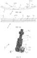
- FIG. 1shows a perspective view of a ring fixation system to the bottom half-ring of which a system of removable walking skates in accordance with the present disclosure are fixed;
- FIG. 2shows a perspective view of only the bottom half-ring with the skates system according to FIG. 1 ;
- FIG. 3shows perspective view of a skates system in accordance with the present disclosure
- FIGS. 4A-4Cshow, respectively, a perspective, front and top view of a skate of the skates system according to the present disclosure
- FIG. 5shows a connecting member for connecting the skate shown in FIG. 4 to the half-ring
- FIGS. 6A-6Cshow, respectively, a perspective, front and cross-sectional view along the line B-B of FIG. 6B of a detail of the connecting member shown in FIG. 5 .
- the reference number 10indicates a skates system according to the present disclosure which can be removably fixed to an external ring fixation system 100 , the latter being shown in FIG. 1 alone.
- the skates system 10comprises a pair of skates 1 which are identical to each other and therefore only one of them will be described in detail.
- the skate 1 according to the present disclosurehas a bottom profile 2 which is curved with a curvature formed in accordance with the technology of the sector.
- a protruding connection body 3in the example arranged centrally, projects from the bottom profile 2 of the skate 1 and extends over a length substantially equal to that of the skate 1 itself.
- the protruding connection body 3forms a kind of fin, the thickness of which in the example is equal to about 1 ⁇ 6th of the width of the skate 1 , understood as being measured transversely with respect to the longitudinal extension of the skate 1 .
- Two slots 3 a and 3 bare formed in the protruding connection body 3 .
- the system 10further comprises at least one connecting member 4 , shown in FIGS. 5 and 6 , having a first end 5 configured to be connected to an opening in the bottom half-ring 101 of the external fixation system 100 and a second end 6 provided with a hole 7 for connection to the slot 3 a , 3 b in the connection body 3 of the skate 1 .
- the protruding connection body 3 of the skate 1has a base 31 with a curved profile substantially parallel to the curved profile of the skate 1 itself and two projecting members or portions 32 a , 32 b protruding from the curved base 31 and spaced from each other.
- Each of the two projecting members 32 a , 32 bcomprises one of the two slots 3 a , 3 b.
- each of said slots 3 a , 3 bhas a longitudinal extension which is parallel to a surface on which the skates 1 rest.
- the slots 3 a , 3 bwhich are oblong, longitudinally do not follow the curved profile of the skate, but are horizontally straight.
- the two slots 3 a , 3 bhave dimensions which are different from each other; more specifically, the slot 3 a which will be arranged in the front of the skate 1 , with respect to the walking direction, has a longitudinal extension smaller than that of the other slot 3 b which will be arranged at the rear.
- the longitudinal extension of the front slot 3 ais equal to about 13 mm
- the longitudinal extension of the slot at the rear 3 bis equal to about 20 mm, in a skate with a length of about 270 mm measured along a flat surface.
- the two projecting members 32 a , 32 bare arranged at a different distance from the respective closest end of the skate 1 .
- the projecting member 32 awhich could be defined as the front part, is placed closer to the front end of the skate 1 compared to the distance between the other projecting member 32 b and the rear-lying end of the skate 1 .
- the two projecting members 32 a , 32 b , and consequently the respective slots 3 a , 3 bare not arranged symmetrically with respect to a transverse central plane of the skate.
- the connecting member 4With reference to the connecting member 4 , it comprises a cylindrical body 41 which extends along a longitudinal axis Z and has a through hole 7 arranged transversely with respect to the longitudinal axis Z of the cylindrical body 41 so as to be able to receive a screw 60 for fixing to the skate 1 .
- the cylindrical body 41also has a removed portion around the hole 7 so as to create a flat wall 42 abutting against the protruding connection body 3 , more precisely abutting against the projecting members 32 a , 32 b .
- This flat wall 42is arranged parallel to the longitudinal axis Z of the cylindrical body 41 .
- the cylindrical body 41also has a blind hole 43 at the opposite end 5 to the through-hole 7 , this blind hole 43 extending along the longitudinal axis Z of the cylindrical body 41 so as to be able to receive a fixing screw 70 for coupling to the bottom side of the half-ring 101 of the external ring fixation system 100 .
- the bottom portion of the skate 1is preferably provided with a tread 11 for dampening the impact of the walking steps.
- the skatein order to fix the skate 1 to the bottom half-ring 101 , the skate is arranged so that the front end is arranged at the front with respect to the walking direction.
- a first connecting member 4is connected to one of the two slots 3 a , 3 b by means of screwing of the screw 60 which will suitably have an operating head 61 .
- a washer 62which may be formed integrally with the screw 60 attached to the head 61 , is suitably arranged between the operating head 61 of the screw 60 and the projecting members 32 a , 32 b of the protruding connection body 3 .
- the exact point for fixing the connecting member 4 to the skatewill be chosen depending on the greater ergonomics which can be perceived by the patient who is using the ring fixation system.
- Fixing the connecting member 4 to the half-ring 101is performed by means of the other screw 70 which is screwed onto the half-ring 101 and passes inside the blind hole 43 .
- Locking nuts 71 and 72may be suitably engaged.
- a first nut 71is arranged between the connecting member 4 and the half-ring 101
- the other nut 72is arranged at the end of the screw 70 which passes through the bottom half-ring 101 and bears against the bottom half-ring 101 .
- skates system according to the present disclosureis able to meet the goals and overcome the drawbacks mentioned above in the introductory part of the present disclosure.
Landscapes
- Health & Medical Sciences (AREA)
- Orthopedic Medicine & Surgery (AREA)
- Life Sciences & Earth Sciences (AREA)
- Surgery (AREA)
- Medical Informatics (AREA)
- General Health & Medical Sciences (AREA)
- Biomedical Technology (AREA)
- Heart & Thoracic Surgery (AREA)
- Nuclear Medicine, Radiotherapy & Molecular Imaging (AREA)
- Molecular Biology (AREA)
- Animal Behavior & Ethology (AREA)
- Engineering & Computer Science (AREA)
- Public Health (AREA)
- Veterinary Medicine (AREA)
- Rehabilitation Tools (AREA)
- Footwear And Its Accessory, Manufacturing Method And Apparatuses (AREA)
- Motorcycle And Bicycle Frame (AREA)
- Orthopedics, Nursing, And Contraception (AREA)
Abstract
Description
Claims (23)
Applications Claiming Priority (4)
| Application Number | Priority Date | Filing Date | Title |
|---|---|---|---|
| EP15425075.7 | 2015-09-29 | ||
| EP15425075.7AEP3150151B1 (en) | 2015-09-29 | 2015-09-29 | Walking skates system removably coupled to an external ring fixation system |
| EP15425075 | 2015-09-29 | ||
| PCT/EP2016/072098WO2017055116A1 (en) | 2015-09-29 | 2016-09-19 | Walking skates system removably coupled to an external ring fixation system |
Publications (2)
| Publication Number | Publication Date |
|---|---|
| US20180310962A1 US20180310962A1 (en) | 2018-11-01 |
| US10743917B2true US10743917B2 (en) | 2020-08-18 |
Family
ID=54697526
Family Applications (1)
| Application Number | Title | Priority Date | Filing Date |
|---|---|---|---|
| US15/764,784ActiveUS10743917B2 (en) | 2015-09-29 | 2016-09-19 | Walking skates system removably coupled to an external ring fixation system |
Country Status (9)
| Country | Link |
|---|---|
| US (1) | US10743917B2 (en) |
| EP (1) | EP3150151B1 (en) |
| JP (1) | JP6824968B2 (en) |
| CN (1) | CN108289698B (en) |
| AU (1) | AU2016333412B2 (en) |
| BR (1) | BR112018006333B1 (en) |
| ES (1) | ES2701502T3 (en) |
| IL (1) | IL258396B (en) |
| WO (1) | WO2017055116A1 (en) |
Cited By (3)
| Publication number | Priority date | Publication date | Assignee | Title |
|---|---|---|---|---|
| US11197692B2 (en)* | 2018-10-24 | 2021-12-14 | Glw, Inc. | External fixation stabilizers, systems, kits, and methods |
| EP4000545A1 (en) | 2020-11-24 | 2022-05-25 | Orthofix S.r.l. | Improved orthopaedic external fixation system with removable rails or skates |
| WO2022112274A1 (en) | 2020-11-24 | 2022-06-02 | Orthofix S.R.L. | Improved orthopaedic external fixation system with removable rails or skates |
Families Citing this family (3)
| Publication number | Priority date | Publication date | Assignee | Title |
|---|---|---|---|---|
| WO2019152784A2 (en)* | 2018-02-05 | 2019-08-08 | Bespa Global, Llc | Implants and methods for treating charcot foot and other conditions |
| US12186258B2 (en)* | 2020-11-24 | 2025-01-07 | Orthofix Srl | Orthopaedic external fixation system with removable rails or skates |
| WO2023147415A2 (en)* | 2022-01-28 | 2023-08-03 | Paragon 28, Inc. | External fixation systems and methods of use |
Citations (9)
| Publication number | Priority date | Publication date | Assignee | Title |
|---|---|---|---|---|
| US3727610A (en)* | 1971-03-16 | 1973-04-17 | P Riniker | Fixator for diaphyses fractures |
| US4360012A (en)* | 1980-02-19 | 1982-11-23 | National Research Development Corporation | External fixation devices for orthopaedic fractures |
| US5152280A (en)* | 1989-01-04 | 1992-10-06 | Confida S.A.S | Bone support device |
| US20120029516A1 (en)* | 2009-04-30 | 2012-02-02 | Jeffrey Taylor | Accessory Device for an Orthopedic Fixator |
| US20120041439A1 (en)* | 2010-08-11 | 2012-02-16 | Stryker Trauma Sa | External fixator system |
| US20120232554A1 (en)* | 2011-03-09 | 2012-09-13 | Quantum Medical Concepts Llc | Alignment Plate for Lower-extremity Ring Fixation, Method of Use, and System |
| US20130204248A1 (en) | 2010-08-11 | 2013-08-08 | Stryker Trauma Sa | External fixator system |
| GB2519650A (en) | 2013-09-05 | 2015-04-29 | Bone Magic Pty Ltd | Foot supporting device |
| US20160256194A1 (en)* | 2014-05-02 | 2016-09-08 | Wright Medical Technology, Inc. | Circular fixator system and method |
Family Cites Families (1)
| Publication number | Priority date | Publication date | Assignee | Title |
|---|---|---|---|---|
| EP2937049B1 (en) | 2013-03-11 | 2019-05-08 | Stryker Trauma SA | External fixator system |
- 2015
- 2015-09-29EPEP15425075.7Apatent/EP3150151B1/enactiveActive
- 2015-09-29ESES15425075Tpatent/ES2701502T3/enactiveActive
- 2016
- 2016-09-19WOPCT/EP2016/072098patent/WO2017055116A1/ennot_activeCeased
- 2016-09-19CNCN201680057013.XApatent/CN108289698B/enactiveActive
- 2016-09-19JPJP2018515859Apatent/JP6824968B2/enactiveActive
- 2016-09-19AUAU2016333412Apatent/AU2016333412B2/enactiveActive
- 2016-09-19USUS15/764,784patent/US10743917B2/enactiveActive
- 2016-09-19BRBR112018006333-9Apatent/BR112018006333B1/enactiveIP Right Grant
- 2018
- 2018-03-27ILIL258396Apatent/IL258396B/enunknown
Patent Citations (9)
| Publication number | Priority date | Publication date | Assignee | Title |
|---|---|---|---|---|
| US3727610A (en)* | 1971-03-16 | 1973-04-17 | P Riniker | Fixator for diaphyses fractures |
| US4360012A (en)* | 1980-02-19 | 1982-11-23 | National Research Development Corporation | External fixation devices for orthopaedic fractures |
| US5152280A (en)* | 1989-01-04 | 1992-10-06 | Confida S.A.S | Bone support device |
| US20120029516A1 (en)* | 2009-04-30 | 2012-02-02 | Jeffrey Taylor | Accessory Device for an Orthopedic Fixator |
| US20120041439A1 (en)* | 2010-08-11 | 2012-02-16 | Stryker Trauma Sa | External fixator system |
| US20130204248A1 (en) | 2010-08-11 | 2013-08-08 | Stryker Trauma Sa | External fixator system |
| US20120232554A1 (en)* | 2011-03-09 | 2012-09-13 | Quantum Medical Concepts Llc | Alignment Plate for Lower-extremity Ring Fixation, Method of Use, and System |
| GB2519650A (en) | 2013-09-05 | 2015-04-29 | Bone Magic Pty Ltd | Foot supporting device |
| US20160256194A1 (en)* | 2014-05-02 | 2016-09-08 | Wright Medical Technology, Inc. | Circular fixator system and method |
Non-Patent Citations (1)
| Title |
|---|
| International Search Report and Written Opinion of the International Searching Authority dated Jan. 2, 2017 in connection with International Application No. PCT/EP2016/072098, 8 pages. |
Cited By (3)
| Publication number | Priority date | Publication date | Assignee | Title |
|---|---|---|---|---|
| US11197692B2 (en)* | 2018-10-24 | 2021-12-14 | Glw, Inc. | External fixation stabilizers, systems, kits, and methods |
| EP4000545A1 (en) | 2020-11-24 | 2022-05-25 | Orthofix S.r.l. | Improved orthopaedic external fixation system with removable rails or skates |
| WO2022112274A1 (en) | 2020-11-24 | 2022-06-02 | Orthofix S.R.L. | Improved orthopaedic external fixation system with removable rails or skates |
Also Published As
| Publication number | Publication date |
|---|---|
| CN108289698A (en) | 2018-07-17 |
| BR112018006333A2 (en) | 2018-10-16 |
| US20180310962A1 (en) | 2018-11-01 |
| ES2701502T8 (en) | 2020-05-26 |
| BR112018006333A8 (en) | 2021-07-27 |
| EP3150151B1 (en) | 2018-09-19 |
| AU2016333412A1 (en) | 2018-04-05 |
| BR112018006333B1 (en) | 2022-07-05 |
| CN108289698B (en) | 2020-11-13 |
| AU2016333412B2 (en) | 2021-01-28 |
| EP3150151A1 (en) | 2017-04-05 |
| JP2018531064A (en) | 2018-10-25 |
| IL258396A (en) | 2018-05-31 |
| WO2017055116A1 (en) | 2017-04-06 |
| IL258396B (en) | 2021-07-29 |
| ES2701502T3 (en) | 2019-02-22 |
| JP6824968B2 (en) | 2021-02-03 |
Similar Documents
| Publication | Publication Date | Title |
|---|---|---|
| US10743917B2 (en) | Walking skates system removably coupled to an external ring fixation system | |
| JP2018531064A6 (en) | Walking skate system removably coupled to an external ring fastening system | |
| JP5784036B2 (en) | Mandibular fixation plate | |
| US20140336012A1 (en) | Achilles stretching devices and methods performed therewith | |
| US7244238B2 (en) | Knee extension apparatus | |
| KR20180078879A (en) | Wire scoliosis proofreading orthosis | |
| ITMI20131590A1 (en) | ANKLE PROSTHESIS | |
| KR20130004370U (en) | Mini plate for genioplasty surgety | |
| CN102885646A (en) | Heel bone anatomical form plastic reset bone fracture plate for heel bone fractures | |
| US20080051782A1 (en) | Auxiliary apparatus for a vertebra surgical operation | |
| CN205360425U (en) | Dual -purpose lacing wire board | |
| ITTO20130138U1 (en) | SPORTS SHOE PROVIDED WITH AN ADJUSTABLE REAR SPOILER | |
| JP2019180567A (en) | Nasal cavity insertion tool | |
| KR20140117031A (en) | Waist protector | |
| US10792028B2 (en) | Double retractor blades | |
| US11065172B2 (en) | Cushioning body for a leg rest of a rollator walking aid | |
| KR20170071776A (en) | the improved detachable backbone support for posture correction | |
| EP3934534A1 (en) | Posture correcting apparatus | |
| CN204219104U (en) | back panel for waist support | |
| JP3210732U (en) | Mounting structure of the prosthetic leg socket for daily use to the back plate spring leg | |
| CN219354621U (en) | Neonate buckles back auxiliary device and buckles back ware | |
| CN114466633A (en) | A prosthetic foot and prosthesis | |
| ITMI20121680A1 (en) | SNOWBOARD ATTACK WITH CONNECTION TO THE PERFECT TABLE. | |
| KR200475058Y1 (en) | Braces for angular deformity | |
| US6837863B2 (en) | Body joint liner |
Legal Events
| Date | Code | Title | Description |
|---|---|---|---|
| FEPP | Fee payment procedure | Free format text:ENTITY STATUS SET TO UNDISCOUNTED (ORIGINAL EVENT CODE: BIG.); ENTITY STATUS OF PATENT OWNER: LARGE ENTITY | |
| STPP | Information on status: patent application and granting procedure in general | Free format text:DOCKETED NEW CASE - READY FOR EXAMINATION | |
| AS | Assignment | Owner name:ORTHOFIX S.R.L., ITALY Free format text:ASSIGNMENT OF ASSIGNORS INTEREST;ASSIGNORS:OTTOBONI, ANDREA;ZACCARIA, ANDREA;SIGNING DATES FROM 20180426 TO 20180502;REEL/FRAME:047694/0945 | |
| STPP | Information on status: patent application and granting procedure in general | Free format text:NON FINAL ACTION MAILED | |
| STPP | Information on status: patent application and granting procedure in general | Free format text:RESPONSE TO NON-FINAL OFFICE ACTION ENTERED AND FORWARDED TO EXAMINER | |
| STPP | Information on status: patent application and granting procedure in general | Free format text:NOTICE OF ALLOWANCE MAILED -- APPLICATION RECEIVED IN OFFICE OF PUBLICATIONS | |
| STPP | Information on status: patent application and granting procedure in general | Free format text:DOCKETED NEW CASE - READY FOR EXAMINATION | |
| STPP | Information on status: patent application and granting procedure in general | Free format text:NOTICE OF ALLOWANCE MAILED -- APPLICATION RECEIVED IN OFFICE OF PUBLICATIONS | |
| AS | Assignment | Owner name:TEXAS SCOTTISH RITE HOSPITAL FOR CHILDREN, TEXAS Free format text:ASSIGNMENT OF ASSIGNORS INTEREST;ASSIGNORS:ROSS, JOHN D.;SAMCHUKOV, MIKHAIL L.;CHERKASHIN, ALEXANDER M.;SIGNING DATES FROM 20190920 TO 20190924;REEL/FRAME:051694/0350 | |
| STPP | Information on status: patent application and granting procedure in general | Free format text:NOTICE OF ALLOWANCE MAILED -- APPLICATION RECEIVED IN OFFICE OF PUBLICATIONS | |
| AS | Assignment | Owner name:ORTHOFIX S.R.L., ITALY Free format text:ASSIGNMENT OF ASSIGNORS INTEREST;ASSIGNOR:BLAKE, STEPHEN VINCENT;REEL/FRAME:052509/0939 Effective date:20200331 | |
| STPP | Information on status: patent application and granting procedure in general | Free format text:PUBLICATIONS -- ISSUE FEE PAYMENT VERIFIED | |
| STCF | Information on status: patent grant | Free format text:PATENTED CASE | |
| AS | Assignment | Owner name:JPMORGAN CHASE BANK, N.A., AS ADMINISTRATIVE AGENT, ILLINOIS Free format text:SECURITY INTEREST;ASSIGNOR:ORTHOFIX S.R.L.;REEL/FRAME:065381/0804 Effective date:20231012 | |
| AS | Assignment | Owner name:ORTHOFIX S.R.L., ITALY Free format text:RELEASE BY SECURED PARTY;ASSIGNOR:JPMORGAN CHASE BANK, N.A.;REEL/FRAME:065609/0233 Effective date:20231106 | |
| MAFP | Maintenance fee payment | Free format text:PAYMENT OF MAINTENANCE FEE, 4TH YEAR, LARGE ENTITY (ORIGINAL EVENT CODE: M1551); ENTITY STATUS OF PATENT OWNER: LARGE ENTITY Year of fee payment:4 |