US10743891B2 - Discectomy instrument - Google Patents
Discectomy instrumentDownload PDFInfo
- Publication number
- US10743891B2 US10743891B2US15/647,724US201715647724AUS10743891B2US 10743891 B2US10743891 B2US 10743891B2US 201715647724 AUS201715647724 AUS 201715647724AUS 10743891 B2US10743891 B2US 10743891B2
- Authority
- US
- United States
- Prior art keywords
- sheath
- guard
- guide
- rod
- channel
- Prior art date
- Legal status (The legal status is an assumption and is not a legal conclusion. Google has not performed a legal analysis and makes no representation as to the accuracy of the status listed.)
- Active, expires
Links
- 238000003780insertionMethods0.000claimsabstractdescription8
- 230000037431insertionEffects0.000claimsabstractdescription8
- 238000000034methodMethods0.000claimsdescription11
- 210000001519tissueAnatomy0.000description11
- 230000001105regulatory effectEffects0.000description3
- 230000008878couplingEffects0.000description2
- 238000010168coupling processMethods0.000description2
- 238000005859coupling reactionMethods0.000description2
- 239000000463materialSubstances0.000description2
- 238000000926separation methodMethods0.000description2
- 230000001154acute effectEffects0.000description1
- 239000007767bonding agentSubstances0.000description1
- 210000000988bone and boneAnatomy0.000description1
- 238000010276constructionMethods0.000description1
- 230000000116mitigating effectEffects0.000description1
Images


Classifications
- A—HUMAN NECESSITIES
- A61—MEDICAL OR VETERINARY SCIENCE; HYGIENE
- A61B—DIAGNOSIS; SURGERY; IDENTIFICATION
- A61B17/00—Surgical instruments, devices or methods
- A61B17/16—Instruments for performing osteoclasis; Drills or chisels for bones; Trepans
- A61B17/1662—Instruments for performing osteoclasis; Drills or chisels for bones; Trepans for particular parts of the body
- A61B17/1671—Instruments for performing osteoclasis; Drills or chisels for bones; Trepans for particular parts of the body for the spine
- A—HUMAN NECESSITIES
- A61—MEDICAL OR VETERINARY SCIENCE; HYGIENE
- A61B—DIAGNOSIS; SURGERY; IDENTIFICATION
- A61B17/00—Surgical instruments, devices or methods
- A61B17/32—Surgical cutting instruments
- A—HUMAN NECESSITIES
- A61—MEDICAL OR VETERINARY SCIENCE; HYGIENE
- A61B—DIAGNOSIS; SURGERY; IDENTIFICATION
- A61B17/00—Surgical instruments, devices or methods
- A61B17/32—Surgical cutting instruments
- A61B17/320016—Endoscopic cutting instruments, e.g. arthroscopes, resectoscopes
- A—HUMAN NECESSITIES
- A61—MEDICAL OR VETERINARY SCIENCE; HYGIENE
- A61B—DIAGNOSIS; SURGERY; IDENTIFICATION
- A61B17/00—Surgical instruments, devices or methods
- A61B17/32—Surgical cutting instruments
- A61B17/3205—Excision instruments
- A—HUMAN NECESSITIES
- A61—MEDICAL OR VETERINARY SCIENCE; HYGIENE
- A61B—DIAGNOSIS; SURGERY; IDENTIFICATION
- A61B17/00—Surgical instruments, devices or methods
- A61B17/16—Instruments for performing osteoclasis; Drills or chisels for bones; Trepans
- A61B17/1613—Component parts
- A61B17/1631—Special drive shafts, e.g. flexible shafts
- A—HUMAN NECESSITIES
- A61—MEDICAL OR VETERINARY SCIENCE; HYGIENE
- A61B—DIAGNOSIS; SURGERY; IDENTIFICATION
- A61B17/00—Surgical instruments, devices or methods
- A61B17/16—Instruments for performing osteoclasis; Drills or chisels for bones; Trepans
- A61B17/1613—Component parts
- A61B17/1633—Sleeves, i.e. non-rotating parts surrounding the bit shaft, e.g. the sleeve forming a single unit with the bit shaft
- A—HUMAN NECESSITIES
- A61—MEDICAL OR VETERINARY SCIENCE; HYGIENE
- A61B—DIAGNOSIS; SURGERY; IDENTIFICATION
- A61B17/00—Surgical instruments, devices or methods
- A61B17/16—Instruments for performing osteoclasis; Drills or chisels for bones; Trepans
- A61B17/1659—Surgical rasps, files, planes, or scrapers
- A—HUMAN NECESSITIES
- A61—MEDICAL OR VETERINARY SCIENCE; HYGIENE
- A61B—DIAGNOSIS; SURGERY; IDENTIFICATION
- A61B17/00—Surgical instruments, devices or methods
- A61B17/16—Instruments for performing osteoclasis; Drills or chisels for bones; Trepans
- A61B17/17—Guides or aligning means for drills, mills, pins or wires
- A61B17/1739—Guides or aligning means for drills, mills, pins or wires specially adapted for particular parts of the body
- A61B17/1757—Guides or aligning means for drills, mills, pins or wires specially adapted for particular parts of the body for the spine
- A—HUMAN NECESSITIES
- A61—MEDICAL OR VETERINARY SCIENCE; HYGIENE
- A61B—DIAGNOSIS; SURGERY; IDENTIFICATION
- A61B17/00—Surgical instruments, devices or methods
- A61B17/00234—Surgical instruments, devices or methods for minimally invasive surgery
- A61B2017/00238—Type of minimally invasive operation
- A61B2017/00261—Discectomy
- A—HUMAN NECESSITIES
- A61—MEDICAL OR VETERINARY SCIENCE; HYGIENE
- A61B—DIAGNOSIS; SURGERY; IDENTIFICATION
- A61B17/00—Surgical instruments, devices or methods
- A61B17/22—Implements for squeezing-off ulcers or the like on inner organs of the body; Implements for scraping-out cavities of body organs, e.g. bones; for invasive removal or destruction of calculus using mechanical vibrations; for removing obstructions in blood vessels, not otherwise provided for
- A61B2017/22082—Implements for squeezing-off ulcers or the like on inner organs of the body; Implements for scraping-out cavities of body organs, e.g. bones; for invasive removal or destruction of calculus using mechanical vibrations; for removing obstructions in blood vessels, not otherwise provided for after introduction of a substance
- A—HUMAN NECESSITIES
- A61—MEDICAL OR VETERINARY SCIENCE; HYGIENE
- A61B—DIAGNOSIS; SURGERY; IDENTIFICATION
- A61B17/00—Surgical instruments, devices or methods
- A61B17/32—Surgical cutting instruments
- A61B2017/320004—Surgical cutting instruments abrasive
- A61B2017/320008—Scrapers
- A—HUMAN NECESSITIES
- A61—MEDICAL OR VETERINARY SCIENCE; HYGIENE
- A61B—DIAGNOSIS; SURGERY; IDENTIFICATION
- A61B17/00—Surgical instruments, devices or methods
- A61B17/32—Surgical cutting instruments
- A61B2017/320052—Guides for cutting instruments
Definitions
- the present disclosurerelates generally to surgical instruments and, more particularly, to an instrument for use in performing a lumbar discectomy.
- the thecal saccan obstruct the desired point of entry into the disc space between the vertebrae, and it can be difficult to move the thecal sac aside and then shield the thecal sac while cutting tools are inserted into the disc space.
- conventional cutting toolscan be difficult to maneuver when removing sections of the disc and/or abrading sections of its adjacent vertebrae.
- a discectomy instrumentin one aspect, includes a flexible shaft and an implement extending from the shaft.
- the instrumentgenerally comprises a guard comprising a shaft and a foot extending therefrom.
- the footcomprising a port and a plurality of teeth.
- a guidecomprises a rod, a finger extending from the rod, and an actuator operably connected to the finger such that the finger is adjustable via the actuator.
- a sheathcomprises at least one channel. The guide and the sheath are coupled to the guard. The channel aligns with the port to permit insertion of the implement through the port via the channel.
- a method for performing a discectomy procedure on a patientgenerally comprises inserting into the patient a guard comprising a shaft and a foot extending therefrom.
- the footcomprises a port and a plurality of teeth.
- a guideis positioned relative to the guard.
- the guidecomprises a rod, a finger extending from the rod, and an actuator operably connected to the finger such that the finger is adjustable via the actuator.
- a sheathis positioned relative to the guard and the guide.
- the sheathcomprises at least one channel. A cutting tool passes through the channel of the sheath and the port of the guard.
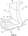
- FIG. 2is an enlarged, fragmented perspective view of the guard of the instrument shown in FIG. 1 ;
- FIG. 3is an enlarged, fragmented perspective view of the guide of the instrument shown in FIG. 1 ;
- FIG. 4 ais a perspective view of the sheath of the instrument shown in FIG. 1 ;
- FIG. 4 bis a top view of the sheath shown in FIG. 4 a;
- FIG. 5 ais a perspective view of one embodiment of a cutting tool suitable for use with the instrument shown in FIG. 1 ;
- FIG. 5 bis a perspective view of another embodiment of a cutting tool suitable for use with the instrument shown in FIG. 1 ;
- FIG. 6is a schematic illustration of the instrument shown in FIG. 1 in use during a discectomy, only a portion of the instrument being seen.
- FIG. 1illustrates one suitable embodiment of a discectomy instrument (indicated generally at 100 ) suitable for use in lumbar discectomy procedures.
- the instrument 100includes: a guard 102 ; a guide 104 configured for coupling to the guard 102 ; and a sheath 106 configured for coupling to the guide 104 and seating between the guard 102 and the guide 104 .
- a cutting tool 108is sized and shaped for insertion through the sheath 106 , and thus is suitable for use with the instrument 100 .
- the instrument 100may have any suitable number of components coupled together in any suitable manner that enables the instrument 100 to function as described herein.
- the illustrated guard 102includes a shaft 110 and a foot 112 extending from the shaft 110 at a joint 114 such that the guard 102 is generally L-shaped.
- the shaft 110has an inner surface 116 and an outer surface 118
- the foot 112has an inner surface 120 and an outer surface 122 .
- the outer surface 118 of the shaft 110is oriented at an acute angle ⁇ (e.g. about 45°) relative to the outer surface 122 of the foot 112 at the joint 114 such that the joint 114 has an exterior profile that is wedge-shaped.
- the illustrated foot 112also has: a tip (or distal end) 124 ; a plurality of teeth 126 (or spikes) extending outward from the outer surface 122 ; a tab 128 outboard of the tip 124 ; and a port 130 extending from the inner surface 120 to the outer surface 122 such that the port 130 extends through the thickness of the foot 112 .
- the joint 114may not have a wedge-shaped profile, and/or the tab 128 may extend inward from any suitable location (i.e., the tab 128 may not be located near the tip 124 in some embodiments).
- the shaft 110 and the foot 112are integrally formed together as a single-piece, unitary structure in the illustrated embodiment, the foot 112 may be suitably coupled to the shaft 110 in other embodiments (i.e., the foot 112 and the shaft 110 may be separately formed structures that are attached together using a suitable mechanism and/or bonding agent).
- the guide 104includes: a rod 132 having a proximal end 134 (shown in FIG. 1 ) and a distal end 136 ; and a finger 138 having a proximal end 140 and a distal end 142 .
- the rod 132also has: a groove 144 (shown in FIG. 1 ) that extends between the proximal end 134 and the distal end 136 ; and a slot 146 located at the distal end 136 and sized to receive the tab 128 of the guard 102 .
- the proximal end 140 of the finger 138is attached to the distal end 136 of the rod 132 , such that the finger 138 extends from the rod 132 to its distal end 142 along a lengthwise axis 148 .
- the finger 138is attached to the rod 132 in the illustrated embodiment, the finger 138 and the rod 132 may be integrally formed together as a single-piece, unitary structure in other embodiments.
- the finger 138has a chute-like shape, in that the finger 138 is curved along the lengthwise axis 148 and has a generally U-shaped (or scalloped) cross-sectional profile 150 along a plane oriented substantially perpendicular to the lengthwise axis 148 .
- the finger 138is made of a flexible material, and the finger 138 is operably coupled to an actuator (e.g., a dial 152 positioned at the proximal end 134 of the rod 132 as shown in FIG. 1 ) such that the finger 138 can be articulated.
- an actuatore.g., a dial 152 positioned at the proximal end 134 of the rod 132 as shown in FIG. 1
- the sheath 106is a generally tubular structure having a proximal end 154 , a distal end 156 , and at least one channel 158 extending from the proximal end 154 to the distal end 156 .
- the sheath 106has a distal channel 160 that is accessible via the distal end 156 , and a plurality of proximal channels 162 (e.g., a first proximal channel 164 and a second proximal channel 166 ) that are accessible via the proximal end 154 such that the proximal channels 162 converge into the distal channel 160 between the proximal end 154 and the distal end 156 .
- proximal channels 162e.g., a first proximal channel 164 and a second proximal channel 166
- the cutting tool 108which is suitable for use with the instrument 100 , has: a flexible shaft 172 (e.g., the shaft 172 may be made of a wire that is counter-wound tightly into coils); and an implement 174 attached to the shaft 172 .
- the implement 174includes at least one blade 176 having a sharp edge 178 for removing softer tissue such as disc tissue (e.g., the blade(s) 176 may be strip-type blade(s) formed into an eggbeater-like shape as shown).
- the implement 174includes at least one blade 176 having a sharp edge 178 for removing softer tissue such as disc tissue (e.g., the blade(s) 176 may be strip-type blade(s) formed into an eggbeater-like shape as shown).
- the implement 174may have any suitable tissue-removal structure (e.g., the implement 174 may be a wire brush such as, for example, a rotating-type wire brush) and/or may not be detachable from the shaft 172 .
- the implement 174may be a wire brush such as, for example, a rotating-type wire brush
- the instrument 100may be used in a variety of discectomy procedures such as, for example, in a full lumbar discectomy to remove the more difficult-to-reach segments of a disc 200 , after the easier-to-reach segments of the disc 200 have already been removed by microdiscectomy. More specifically, to use the instrument 100 , the wedge-shaped joint 114 of the guard 102 is first manipulated to gently move the thecal sac 202 aside, and the teeth 126 of the foot 112 are then firmly seated (or anchored) against a vertebra 204 of the patient's spinal column 206 such that the port 130 is positioned over a desired point of entry 208 into the associated disc space 210 .
- the guide 104is coupled to the foot 112 such that the tab 128 of the foot 112 is inserted into the slot 146 of the guide 104 .
- the sheath 106is then coupled between the shaft 110 of the guard 102 and the rod 132 of the guide 104 by inserting the rib 168 of the sheath 106 into the groove 144 of the guide 104 , and sliding the sheath 106 longitudinally along the rod 132 of the guide 104 until the distal end 156 of the sheath 106 is seated against the foot 112 of the guard 102 , with the distal channel 160 of the sheath 106 laterally aligned with the port 130 of the guard 102 (and, hence, laterally aligned with the desired point of entry 208 into the disc space 210 ).
- the guide 104is laterally fixed to the guard 102
- the sheath 106is laterally fixed to the guide 104 , such that lateral separation of the components is inhibit
- the cutting tool 108(having an appropriate implement 174 coupled to the shaft 172 ) is inserted into either the first proximal channel 164 or the second proximal channel 166 of the sheath 106 such that the implement 174 passes through the distal channel 160 of the sheath 106 and through the port 130 of the guard 102 , into the disc space 210 via the point of entry 208 .
- the cutting tool 108 and/or the sheath 106may have an adjustable slide-stop or gauge (e.g., an adjustable stop ring 184 ) that facilitates regulating how far the cutting tool 108 is insertable into the sheath 106 and, hence, regulating how far the implement 174 can protrude from the sheath 106 , thereby regulating the depth at which the cutting tool 108 is insertable into the disc space 210 .
- an adjustable slide-stop or gaugee.g., an adjustable stop ring 184
- the cutting tool 108is suitably operable (e.g., rotatable) to remove the softer tissue of the disc 200 and/or the harder tissue of the adjacent vertebra 204 .
- the finger 138 of the guide 104facilitates directing the cutting tool 108 into different areas of the disc space 210 .
- the profile 150 of the finger 138facilitates keeping the implement 174 from straying off a desired course, and the adjustable curvature of the finger 138 (e.g., via the dial 152 ) provides the surgeon with enhanced coverage and control when accurately and precisely moving the implement 174 from one area of the disc space 210 to another.
- the guard 102 and the sheath 106facilitate shielding the thecal sac 202 from the implement 174 (and the teeth 126 ) when the instrument 100 is in use, thereby mitigating morbidity of the thecal sac 202 as a result of the discectomy procedure.
- the surgeonmay choose a blade-like implement 174 ( FIG. 5 a ), an abrasive implement 174 ( FIG.
- any other suitable implemente.g., a rotating-type wire brush implement
- any other suitable implemente.g., a rotating-type wire brush implement
- a rotating-type wire brush implementfor insertion into the disc space 210 to respectively cut softer disc tissue, grind harder vertebra tissue, or perform any other suitable type of tissue-removal step in the overall procedure.
- the surgeoncan have multiple surgical tools of different types (e.g., cutting tool(s), a suction tool, etc.) simultaneously inserted into the sheath 106 to provide a more instantaneous and interchangeable deployment of such tools into the disc space 210 via the port 130 .
- the cutting tool 108may be inserted into the first proximal channel 164 , while a suction hose (not shown) is simultaneously inserted into the second proximal channel 166 , such that each is selectively insertable into the disc space 210 .
- the surgeonmay insert the cutting tool 108 into the disc space 210 for removing tissue, and then retract the implement 174 into the first proximal channel 164 before inserting the suction hose into the disc space 210 to clear the removed tissue from the disc space 210 .
- the suction hosemay then be retracted into the second proximal channel 166 , before reinserting the cutting tool 108 into the disc space 210 for removing more tissue. This process is repeatable as desired.
Landscapes
- Health & Medical Sciences (AREA)
- Surgery (AREA)
- Life Sciences & Earth Sciences (AREA)
- Medical Informatics (AREA)
- Animal Behavior & Ethology (AREA)
- Engineering & Computer Science (AREA)
- Biomedical Technology (AREA)
- Heart & Thoracic Surgery (AREA)
- Veterinary Medicine (AREA)
- Molecular Biology (AREA)
- Nuclear Medicine, Radiotherapy & Molecular Imaging (AREA)
- General Health & Medical Sciences (AREA)
- Public Health (AREA)
- Orthopedic Medicine & Surgery (AREA)
- Dentistry (AREA)
- Oral & Maxillofacial Surgery (AREA)
- Surgical Instruments (AREA)
Abstract
Description
Claims (18)
Priority Applications (1)
| Application Number | Priority Date | Filing Date | Title |
|---|---|---|---|
| US15/647,724US10743891B2 (en) | 2016-07-13 | 2017-07-12 | Discectomy instrument |
Applications Claiming Priority (2)
| Application Number | Priority Date | Filing Date | Title |
|---|---|---|---|
| US201662361756P | 2016-07-13 | 2016-07-13 | |
| US15/647,724US10743891B2 (en) | 2016-07-13 | 2017-07-12 | Discectomy instrument |
Publications (2)
| Publication Number | Publication Date |
|---|---|
| US20180014837A1 US20180014837A1 (en) | 2018-01-18 |
| US10743891B2true US10743891B2 (en) | 2020-08-18 |
Family
ID=60942008
Family Applications (1)
| Application Number | Title | Priority Date | Filing Date |
|---|---|---|---|
| US15/647,724Active2038-08-12US10743891B2 (en) | 2016-07-13 | 2017-07-12 | Discectomy instrument |
Country Status (1)
| Country | Link |
|---|---|
| US (1) | US10743891B2 (en) |
Citations (24)
| Publication number | Priority date | Publication date | Assignee | Title |
|---|---|---|---|---|
| US20030191474A1 (en)* | 2000-02-16 | 2003-10-09 | Cragg Andrew H. | Apparatus for performing a discectomy through a trans-sacral axial bore within the vertebrae of the spine |
| US20040127963A1 (en)* | 1999-01-25 | 2004-07-01 | Uchida Andy H. | Intervertebral decompression |
| US20050203527A1 (en)* | 2004-03-03 | 2005-09-15 | Scimed Life Systems, Inc. | Apparatus and methods for removing vertebral bone and disc tissue |
| US20050209622A1 (en)* | 2004-03-03 | 2005-09-22 | Scimed Life Systems, Inc. | Tissue removal probe with irrigation and aspiration ports |
| US20060184188A1 (en)* | 2002-11-08 | 2006-08-17 | Li Lehmann K | Transpedicular intervertebral disk access methods and devices |
| US20070027464A1 (en)* | 2005-07-29 | 2007-02-01 | X-Sten, Corp. | Device for resecting spinal tissue |
| US7309338B2 (en) | 2000-02-16 | 2007-12-18 | Trans1 Inc. | Methods and apparatus for performing therapeutic procedures in the spine |
| US20080195081A1 (en) | 2007-02-02 | 2008-08-14 | Hansen Medical, Inc. | Spinal surgery methods using a robotic instrument system |
| US7738969B2 (en)* | 2004-10-15 | 2010-06-15 | Baxano, Inc. | Devices and methods for selective surgical removal of tissue |
| US20110087257A1 (en)* | 2009-04-02 | 2011-04-14 | Spine View, Inc. | Minimally invasive discectomy |
| US20110112373A1 (en) | 2009-11-10 | 2011-05-12 | Trans1 Inc. | Soft tissue access apparatus and methods for spinal surgery |
| US20110313529A1 (en)* | 2008-12-23 | 2011-12-22 | Benvenue Medical, Inc. | Tissue Removal Tools And Methods Of Use |
| US20120184910A1 (en) | 2009-10-01 | 2012-07-19 | Kevin Woehr | Catheter insertion device |
| US8353909B2 (en)* | 1988-06-13 | 2013-01-15 | Warsaw Orthopedic, Inc. | Surgical instrument for distracting a spinal disc space |
| US20130018376A1 (en)* | 2011-07-15 | 2013-01-17 | Samuel Yoon | Devices and Methods For the Preparation of Intervertebral Discs |
| US8382841B2 (en) | 2004-01-09 | 2013-02-26 | Kent D. Yundt | Method, system and apparatus for interbody fusion |
| US20130197551A1 (en)* | 2012-01-31 | 2013-08-01 | Samuel Yoon | Surgical Disc Removal Tool |
| US20130211438A1 (en)* | 2010-06-30 | 2013-08-15 | Laurimed, Llc | Devices and methods for cutting tissue |
| US20140276832A1 (en)* | 2013-03-14 | 2014-09-18 | Nadi Salah Hibri | Surgical Device |
| US8852243B2 (en) | 2011-03-10 | 2014-10-07 | Interventional Spine, Inc. | Method and apparatus for minimally invasive insertion of intervertebral implants |
| US20140303730A1 (en)* | 2011-11-30 | 2014-10-09 | Beth Israel Deaconess Medical Center | Systems and methods for endoscopic vertebral fusion |
| US20150080896A1 (en)* | 2013-07-19 | 2015-03-19 | Ouroboros Medical, Inc. | Anti-clogging device for a vacuum-assisted, tissue removal system |
| US20160030060A1 (en)* | 2014-07-31 | 2016-02-04 | Amendia, Inc. | Vertical cutter and method of use |
| US20180064461A1 (en)* | 2016-09-07 | 2018-03-08 | Vertos Medical, Inc. | Percutaneous lateral recess resection methods and instruments |
- 2017
- 2017-07-12USUS15/647,724patent/US10743891B2/enactiveActive
Patent Citations (24)
| Publication number | Priority date | Publication date | Assignee | Title |
|---|---|---|---|---|
| US8353909B2 (en)* | 1988-06-13 | 2013-01-15 | Warsaw Orthopedic, Inc. | Surgical instrument for distracting a spinal disc space |
| US20040127963A1 (en)* | 1999-01-25 | 2004-07-01 | Uchida Andy H. | Intervertebral decompression |
| US7309338B2 (en) | 2000-02-16 | 2007-12-18 | Trans1 Inc. | Methods and apparatus for performing therapeutic procedures in the spine |
| US20030191474A1 (en)* | 2000-02-16 | 2003-10-09 | Cragg Andrew H. | Apparatus for performing a discectomy through a trans-sacral axial bore within the vertebrae of the spine |
| US20060184188A1 (en)* | 2002-11-08 | 2006-08-17 | Li Lehmann K | Transpedicular intervertebral disk access methods and devices |
| US8382841B2 (en) | 2004-01-09 | 2013-02-26 | Kent D. Yundt | Method, system and apparatus for interbody fusion |
| US20050209622A1 (en)* | 2004-03-03 | 2005-09-22 | Scimed Life Systems, Inc. | Tissue removal probe with irrigation and aspiration ports |
| US20050203527A1 (en)* | 2004-03-03 | 2005-09-15 | Scimed Life Systems, Inc. | Apparatus and methods for removing vertebral bone and disc tissue |
| US7738969B2 (en)* | 2004-10-15 | 2010-06-15 | Baxano, Inc. | Devices and methods for selective surgical removal of tissue |
| US20070027464A1 (en)* | 2005-07-29 | 2007-02-01 | X-Sten, Corp. | Device for resecting spinal tissue |
| US20080195081A1 (en) | 2007-02-02 | 2008-08-14 | Hansen Medical, Inc. | Spinal surgery methods using a robotic instrument system |
| US20110313529A1 (en)* | 2008-12-23 | 2011-12-22 | Benvenue Medical, Inc. | Tissue Removal Tools And Methods Of Use |
| US20110087257A1 (en)* | 2009-04-02 | 2011-04-14 | Spine View, Inc. | Minimally invasive discectomy |
| US20120184910A1 (en) | 2009-10-01 | 2012-07-19 | Kevin Woehr | Catheter insertion device |
| US20110112373A1 (en) | 2009-11-10 | 2011-05-12 | Trans1 Inc. | Soft tissue access apparatus and methods for spinal surgery |
| US20130211438A1 (en)* | 2010-06-30 | 2013-08-15 | Laurimed, Llc | Devices and methods for cutting tissue |
| US8852243B2 (en) | 2011-03-10 | 2014-10-07 | Interventional Spine, Inc. | Method and apparatus for minimally invasive insertion of intervertebral implants |
| US20130018376A1 (en)* | 2011-07-15 | 2013-01-17 | Samuel Yoon | Devices and Methods For the Preparation of Intervertebral Discs |
| US20140303730A1 (en)* | 2011-11-30 | 2014-10-09 | Beth Israel Deaconess Medical Center | Systems and methods for endoscopic vertebral fusion |
| US20130197551A1 (en)* | 2012-01-31 | 2013-08-01 | Samuel Yoon | Surgical Disc Removal Tool |
| US20140276832A1 (en)* | 2013-03-14 | 2014-09-18 | Nadi Salah Hibri | Surgical Device |
| US20150080896A1 (en)* | 2013-07-19 | 2015-03-19 | Ouroboros Medical, Inc. | Anti-clogging device for a vacuum-assisted, tissue removal system |
| US20160030060A1 (en)* | 2014-07-31 | 2016-02-04 | Amendia, Inc. | Vertical cutter and method of use |
| US20180064461A1 (en)* | 2016-09-07 | 2018-03-08 | Vertos Medical, Inc. | Percutaneous lateral recess resection methods and instruments |
Also Published As
| Publication number | Publication date |
|---|---|
| US20180014837A1 (en) | 2018-01-18 |
Similar Documents
| Publication | Publication Date | Title |
|---|---|---|
| JP7235786B2 (en) | Bone marrow access device and system including bone marrow access device | |
| US8623021B2 (en) | Facet joint reamer | |
| EP2236100B1 (en) | Microfracture instrument | |
| US8632561B2 (en) | Surgical cutting device and method for performing surgery | |
| EP2624762B1 (en) | Bone marrow harvesting device having flexible needle | |
| US20210251639A1 (en) | Cartilage removal tool and method | |
| US8647257B2 (en) | Cannulotome | |
| US20070093841A1 (en) | Surgical drill, a set of surgical drills, a system for cutting bone and a method for removing bone | |
| US20080051812A1 (en) | Multi-Wire Tissue Cutter | |
| US20120265250A1 (en) | Transpedicular access to intervertebral spaces and related spinal fusion systems and methods | |
| JP2007516738A5 (en) | ||
| KR20120120251A (en) | An undercutting system for preparing sacroiliac fusion | |
| CN111885972B (en) | Instrument sets for spinal surgery | |
| US20080243163A1 (en) | Perforating Trocar | |
| EP1972288A1 (en) | Shaver blade with depth markings | |
| US8070689B2 (en) | Perforating trocar | |
| CA2661869A1 (en) | Tissue access guidewire system and method | |
| WO2015026793A1 (en) | Bone removal under direct visualization | |
| US20150201915A1 (en) | Biopsy assembly for obtaining a tissue sample | |
| CN104918569B (en) | Surgical kit for inserting an access tube into an intervertebral disc of a patient | |
| US10743891B2 (en) | Discectomy instrument | |
| US11980387B2 (en) | Cutting tool for the vertical incision of a tendon | |
| US11925393B2 (en) | Pedicle screw rasp system and adjuster | |
| WO2001006938A1 (en) | Flexor rectinaculum incision surgical device | |
| JP7456623B2 (en) | Instrument set for spine surgery |
Legal Events
| Date | Code | Title | Description |
|---|---|---|---|
| STPP | Information on status: patent application and granting procedure in general | Free format text:DOCKETED NEW CASE - READY FOR EXAMINATION | |
| AS | Assignment | Owner name:WASHINGTON UNIVERSITY, MISSOURI Free format text:ASSIGNMENT OF ASSIGNORS INTEREST;ASSIGNORS:LEUTHARDT, ERIC C.;WRIGHT, NEILL MARSHALL;MORAN, DANIEL;AND OTHERS;SIGNING DATES FROM 20170713 TO 20170814;REEL/FRAME:044489/0221 | |
| STPP | Information on status: patent application and granting procedure in general | Free format text:NON FINAL ACTION MAILED | |
| STPP | Information on status: patent application and granting procedure in general | Free format text:RESPONSE TO NON-FINAL OFFICE ACTION ENTERED AND FORWARDED TO EXAMINER | |
| STPP | Information on status: patent application and granting procedure in general | Free format text:NON FINAL ACTION MAILED | |
| STPP | Information on status: patent application and granting procedure in general | Free format text:FINAL REJECTION MAILED | |
| STPP | Information on status: patent application and granting procedure in general | Free format text:NOTICE OF ALLOWANCE MAILED -- APPLICATION RECEIVED IN OFFICE OF PUBLICATIONS | |
| STCF | Information on status: patent grant | Free format text:PATENTED CASE | |
| MAFP | Maintenance fee payment | Free format text:PAYMENT OF MAINTENANCE FEE, 4TH YEAR, MICRO ENTITY (ORIGINAL EVENT CODE: M3551); ENTITY STATUS OF PATENT OWNER: MICROENTITY Year of fee payment:4 |