US10742847B2 - Devices and methods for high dynamic range video - Google Patents
Devices and methods for high dynamic range videoDownload PDFInfo
- Publication number
- US10742847B2 US10742847B2US16/376,146US201916376146AUS10742847B2US 10742847 B2US10742847 B2US 10742847B2US 201916376146 AUS201916376146 AUS 201916376146AUS 10742847 B2US10742847 B2US 10742847B2
- Authority
- US
- United States
- Prior art keywords
- sensor
- pixel values
- pixel
- sensors
- values
- Prior art date
- Legal status (The legal status is an assumption and is not a legal conclusion. Google has not performed a legal analysis and makes no representation as to the accuracy of the status listed.)
- Active
Links
Images


Classifications
- H—ELECTRICITY
- H04—ELECTRIC COMMUNICATION TECHNIQUE
- H04N—PICTORIAL COMMUNICATION, e.g. TELEVISION
- H04N1/00—Scanning, transmission or reproduction of documents or the like, e.g. facsimile transmission; Details thereof
- H04N1/00002—Diagnosis, testing or measuring; Detecting, analysing or monitoring not otherwise provided for
- H04N1/00026—Methods therefor
- H04N1/00068—Calculating or estimating
- H—ELECTRICITY
- H04—ELECTRIC COMMUNICATION TECHNIQUE
- H04N—PICTORIAL COMMUNICATION, e.g. TELEVISION
- H04N1/00—Scanning, transmission or reproduction of documents or the like, e.g. facsimile transmission; Details thereof
- H04N1/46—Colour picture communication systems
- H04N1/56—Processing of colour picture signals
- H04N1/60—Colour correction or control
- H04N1/6027—Correction or control of colour gradation or colour contrast
- G—PHYSICS
- G02—OPTICS
- G02B—OPTICAL ELEMENTS, SYSTEMS OR APPARATUS
- G02B27/00—Optical systems or apparatus not provided for by any of the groups G02B1/00 - G02B26/00, G02B30/00
- G02B27/10—Beam splitting or combining systems
- G02B27/1006—Beam splitting or combining systems for splitting or combining different wavelengths
- G02B27/1013—Beam splitting or combining systems for splitting or combining different wavelengths for colour or multispectral image sensors, e.g. splitting an image into monochromatic image components on respective sensors
- G—PHYSICS
- G06—COMPUTING OR CALCULATING; COUNTING
- G06T—IMAGE DATA PROCESSING OR GENERATION, IN GENERAL
- G06T11/00—2D [Two Dimensional] image generation
- G06T11/60—Editing figures and text; Combining figures or text
- G06T5/002—
- G—PHYSICS
- G06—COMPUTING OR CALCULATING; COUNTING
- G06T—IMAGE DATA PROCESSING OR GENERATION, IN GENERAL
- G06T5/00—Image enhancement or restoration
- G06T5/70—Denoising; Smoothing
- G—PHYSICS
- G06—COMPUTING OR CALCULATING; COUNTING
- G06T—IMAGE DATA PROCESSING OR GENERATION, IN GENERAL
- G06T7/00—Image analysis
- G06T7/90—Determination of colour characteristics
- H—ELECTRICITY
- H04—ELECTRIC COMMUNICATION TECHNIQUE
- H04N—PICTORIAL COMMUNICATION, e.g. TELEVISION
- H04N1/00—Scanning, transmission or reproduction of documents or the like, e.g. facsimile transmission; Details thereof
- H04N1/46—Colour picture communication systems
- H04N1/56—Processing of colour picture signals
- H04N1/60—Colour correction or control
- H04N1/603—Colour correction or control controlled by characteristics of the picture signal generator or the picture reproducer
- H—ELECTRICITY
- H04—ELECTRIC COMMUNICATION TECHNIQUE
- H04N—PICTORIAL COMMUNICATION, e.g. TELEVISION
- H04N17/00—Diagnosis, testing or measuring for television systems or their details
- H04N17/002—Diagnosis, testing or measuring for television systems or their details for television cameras
- H—ELECTRICITY
- H04—ELECTRIC COMMUNICATION TECHNIQUE
- H04N—PICTORIAL COMMUNICATION, e.g. TELEVISION
- H04N21/00—Selective content distribution, e.g. interactive television or video on demand [VOD]
- H04N21/20—Servers specifically adapted for the distribution of content, e.g. VOD servers; Operations thereof
- H04N21/23—Processing of content or additional data; Elementary server operations; Server middleware
- H04N21/234—Processing of video elementary streams, e.g. splicing of video streams or manipulating encoded video stream scene graphs
- H04N21/2343—Processing of video elementary streams, e.g. splicing of video streams or manipulating encoded video stream scene graphs involving reformatting operations of video signals for distribution or compliance with end-user requests or end-user device requirements
- H04N21/23439—Processing of video elementary streams, e.g. splicing of video streams or manipulating encoded video stream scene graphs involving reformatting operations of video signals for distribution or compliance with end-user requests or end-user device requirements for generating different versions
- H—ELECTRICITY
- H04—ELECTRIC COMMUNICATION TECHNIQUE
- H04N—PICTORIAL COMMUNICATION, e.g. TELEVISION
- H04N21/00—Selective content distribution, e.g. interactive television or video on demand [VOD]
- H04N21/20—Servers specifically adapted for the distribution of content, e.g. VOD servers; Operations thereof
- H04N21/23—Processing of content or additional data; Elementary server operations; Server middleware
- H04N21/236—Assembling of a multiplex stream, e.g. transport stream, by combining a video stream with other content or additional data, e.g. inserting a URL [Uniform Resource Locator] into a video stream, multiplexing software data into a video stream; Remultiplexing of multiplex streams; Insertion of stuffing bits into the multiplex stream, e.g. to obtain a constant bit-rate; Assembling of a packetised elementary stream
- H04N21/2365—Multiplexing of several video streams
- H—ELECTRICITY
- H04—ELECTRIC COMMUNICATION TECHNIQUE
- H04N—PICTORIAL COMMUNICATION, e.g. TELEVISION
- H04N23/00—Cameras or camera modules comprising electronic image sensors; Control thereof
- H04N23/10—Cameras or camera modules comprising electronic image sensors; Control thereof for generating image signals from different wavelengths
- H04N23/13—Cameras or camera modules comprising electronic image sensors; Control thereof for generating image signals from different wavelengths with multiple sensors
- H—ELECTRICITY
- H04—ELECTRIC COMMUNICATION TECHNIQUE
- H04N—PICTORIAL COMMUNICATION, e.g. TELEVISION
- H04N23/00—Cameras or camera modules comprising electronic image sensors; Control thereof
- H04N23/45—Cameras or camera modules comprising electronic image sensors; Control thereof for generating image signals from two or more image sensors being of different type or operating in different modes, e.g. with a CMOS sensor for moving images in combination with a charge-coupled device [CCD] for still images
- H—ELECTRICITY
- H04—ELECTRIC COMMUNICATION TECHNIQUE
- H04N—PICTORIAL COMMUNICATION, e.g. TELEVISION
- H04N23/00—Cameras or camera modules comprising electronic image sensors; Control thereof
- H04N23/70—Circuitry for compensating brightness variation in the scene
- H04N23/741—Circuitry for compensating brightness variation in the scene by increasing the dynamic range of the image compared to the dynamic range of the electronic image sensors
- H—ELECTRICITY
- H04—ELECTRIC COMMUNICATION TECHNIQUE
- H04N—PICTORIAL COMMUNICATION, e.g. TELEVISION
- H04N23/00—Cameras or camera modules comprising electronic image sensors; Control thereof
- H04N23/80—Camera processing pipelines; Components thereof
- H04N23/84—Camera processing pipelines; Components thereof for processing colour signals
- H04N23/85—Camera processing pipelines; Components thereof for processing colour signals for matrixing
- H04N5/2258—
- H04N5/2355—
- H—ELECTRICITY
- H04—ELECTRIC COMMUNICATION TECHNIQUE
- H04N—PICTORIAL COMMUNICATION, e.g. TELEVISION
- H04N5/00—Details of television systems
- H04N5/222—Studio circuitry; Studio devices; Studio equipment
- H04N5/262—Studio circuits, e.g. for mixing, switching-over, change of character of image, other special effects ; Cameras specially adapted for the electronic generation of special effects
- H04N5/265—Mixing
- H04N9/09—
- H—ELECTRICITY
- H04—ELECTRIC COMMUNICATION TECHNIQUE
- H04N—PICTORIAL COMMUNICATION, e.g. TELEVISION
- H04N9/00—Details of colour television systems
- H04N9/64—Circuits for processing colour signals
- H04N9/646—Circuits for processing colour signals for image enhancement, e.g. vertical detail restoration, cross-colour elimination, contour correction, chrominance trapping filters
- H—ELECTRICITY
- H04—ELECTRIC COMMUNICATION TECHNIQUE
- H04N—PICTORIAL COMMUNICATION, e.g. TELEVISION
- H04N9/00—Details of colour television systems
- H04N9/64—Circuits for processing colour signals
- H04N9/67—Circuits for processing colour signals for matrixing
- G—PHYSICS
- G06—COMPUTING OR CALCULATING; COUNTING
- G06T—IMAGE DATA PROCESSING OR GENERATION, IN GENERAL
- G06T2207/00—Indexing scheme for image analysis or image enhancement
- G06T2207/10—Image acquisition modality
- G06T2207/10024—Color image
- G—PHYSICS
- G06—COMPUTING OR CALCULATING; COUNTING
- G06T—IMAGE DATA PROCESSING OR GENERATION, IN GENERAL
- G06T2207/00—Indexing scheme for image analysis or image enhancement
- G06T2207/10—Image acquisition modality
- G06T2207/10141—Special mode during image acquisition
- G06T2207/10144—Varying exposure
- G—PHYSICS
- G06—COMPUTING OR CALCULATING; COUNTING
- G06T—IMAGE DATA PROCESSING OR GENERATION, IN GENERAL
- G06T2207/00—Indexing scheme for image analysis or image enhancement
- G06T2207/20—Special algorithmic details
- G06T2207/20172—Image enhancement details
- G06T2207/20208—High dynamic range [HDR] image processing
- G—PHYSICS
- G06—COMPUTING OR CALCULATING; COUNTING
- G06T—IMAGE DATA PROCESSING OR GENERATION, IN GENERAL
- G06T2207/00—Indexing scheme for image analysis or image enhancement
- G06T2207/20—Special algorithmic details
- G06T2207/20212—Image combination
- G06T2207/20221—Image fusion; Image merging
Definitions
- This disclosurerelates to real-time capture and production of high dynamic range video.
- the human visual systemis capable of identifying and processing visual features with high dynamic range. For example, real-world scenes with contrast ratios of 1,000,000:1 or greater can be accurately processed by the human visual cortex.
- most image acquisition devicesare only capable of reproducing or capturing low dynamic range, resulting in a loss of image accuracy. The problem is ever more significant in video imaging.
- Methods and devices of the inventionprocess streams of pixels from multiple sensors in a frame-independent manner, resulting in real-time High Dynamic Range (HDR) video production.
- the real-time aspect of the inventionis accomplished by analyzing streams of pixels from the various sensors without reference to the frame to which those pixels belong.
- the frame-independent nature of the inventionmeans that there is no need to wait for an entire frame of data to be read from a sensor before processing pixel data.
- the resultis an HDR video that has a dynamic range greater than the range that can be obtained using a single image sensor, typically 8 bits in depth.
- the multiple image sensors used in the inventionare exposed to identical scenes with different light levels and each produces an ordered stream of pixel values that are processed in real-time and independent of frame in which they will reside.
- the video processing pipeline used to produce HDR imagesincludes kernel and merge operations that include identifying saturated pixel values and merging streams of pixel values.
- the merging operationincludes replacing saturated pixel values with corresponding pixel values originating from a different sensor.
- the resulting productis high dynamic range video output.
- the kernel and merge operationsprocess pixel values as they stream through the pipeline, no post-processing is required to produce HDR video.
- a CMOS sensorhas millions of pixels, but the first pixel values to stream off of that sensor may be processed by the kernel operation or even enter the merge operation before a pixel value from, e.g., the millionth pixel from that same sensor even reaches the processing device.
- the frame-independent pixel processing systems and methods of the inventionproduce true real-time HDR video.
- a synchronization module in the pipelinesynchronizes the streams of pixel values arriving from the sensors. This means that when, for example, the 60 th pixel from a first sensor enters the kernel operation, the 60 th pixel from each of the other sensors is also simultaneously entering the kernel operation. As a result, pixel values from corresponding pixels on different sensors flow through the pipeline synchronously. This allows two things. First, the synchronization module can correct small phase discrepancies in data arrival times to the system from multiple sensors.). Second, the synchronization allows the kernel operation to consider—for a given pixel value from a specific pixel on one of the image sensors—values from the neighborhood of surrounding pixels on that sensor and also consider values from a corresponding neighborhood of pixels on another of the image sensors. This allows the kernel operation to create an estimated value for a saturated pixel from one sensor based on a pattern of values from the surrounding neighborhood on the same or another sensor.
- the HDR pipelinecan also correct for differences in spectral characteristics of each of the multiple sensors.
- Optical componentssuch as beamsplitters, lenses, or filters—even if purported to be spectrally neutral—may have slight wavelength-dependent differences in the amounts of light transmitted. That is, each image sensor may be said to have its own “color correction space” whereby images from that sensor need to be corrected out of that color correction space to true color.
- the optical systemcan be calibrated (e.g., by taking a picture of a calibration card) and a color correction matrix can be determined and stored for each image sensor.
- the HDR video pipelinecan then perform the counter-intuitive step of adjusting the pixel values from one sensor toward the color correction space of another sensor—which may in some cases involve nudging the colors away from true color.
- a preferred pipelineincludes other processing modules as described in detail in the Detailed Description of the invention below.
- the inventionprovides methods for producing real-time HDR video.
- Methodsinclude streaming pixel values from each of multiple sensors in a frame independent-manner through a pipeline on a processing device, such as a field-programmable gate array or an application-specific integrated circuit.
- the pipelineincludes a kernel operation that identifies saturated pixel values.
- the pixel valuesare merged to produce an HDR image.
- the merging stepexcludes at least some of the saturated pixel values from the resulting HDR image.
- the multiple image sensorspreferably capture images simultaneously through a single lens. Incoming light is received through the lens and split via at least one beamsplitter onto the multiple image sensors, such that at least about 95% of the light gathered by the lens is captured by the multiple image sensors.
- the multiple image sensorsmay include at least a high exposure (HE) sensor and a middle exposure (ME) sensor.
- Merging pixel streamsmay include using HE pixel values that are not saturated and ME pixel values corresponding to the saturated pixel values.
- the multiple sensorsmay further include a low exposure (LE) sensor, and the method may include identifying saturated pixel values originating from both the HE sensor and the ME sensor.
- the obtaining, streaming, and merging stepsmay include streaming the sequences of pixel values through a pipeline on the processing device such that no location on the processing device stores a complete image.
- Sequences of pixel valuesare streamed through the processing device and merged without waiting to receive pixel values from all pixels on the image sensors. Because the pixel values are streamed through a pipeline, at least some of the saturated pixel values may be identified before receiving values from all pixels from the image sensors. Methods of the invention may include beginning to merge portions of the sequences while still streaming later-arriving pixel values through the kernel operation.
- streaming the pixel values through the kernel operationincludes examining values from a neighborhood of pixels surrounding a first pixel on the HE sensor, finding saturated values in the neighborhood of pixels, and using information from a corresponding neighborhood on the ME sensor to estimate a value for the first pixel.
- the pixel valuesmay be streamed through the kernel operation via a path within the processing device that momentarily stores a value from the first pixel proximal to each value originating from the neighborhood of pixels.
- Each of the image sensorsmay include a color filter array, and the method may include demosaicing the HDR imaging after the merging.
- the multiple image sensorspreferably capture images that are optically identical except for light level.
- a first pixel value from a first pixel on one of the image sensorsmay be identified as saturated if it is above some specified level, for example at least about 90% of a maximum possible pixel value.
- the apparatusincludes a processing device (e.g., FPGA or ASIC) and a plurality of image sensors coupled to the processing device.
- the apparatusis configured to stream pixel values from each of the plurality of image sensors in a frame independent-manner through a pipeline on the processing device.
- the pipelineincludes a kernel operation that identifies saturated pixel values and a merge module to merge the pixel values to produce an HDR image.
- the apparatusmay use or be connected to a single lens and one or more beamsplitters.
- the plurality of image sensorsincludes at least a high exposure (HE) sensor and a middle exposure (ME) sensor.
- the HE sensor, the ME sensor, the lens and the beamsplittersmay be arranged to receive an incoming beam of light and split the beam of light into at least a first path that impinges on the HE sensor and a second path that impinges on the ME sensor.
- the beamsplitterdirects a majority of the light to the first path and a lesser amount of the light to the second path.
- the first path and the second pathimpinge on the HE and the ME sensor, respectively, to generate images that are optically identical but for light level.
- the kernel operationmay operate on pixel values as they stream from each of the plurality of image sensors by examining, for any given pixel on the HE sensor, values from a neighborhood of pixels surrounding the given pixel, finding saturated values in the neighborhood of pixels, and using information from a corresponding neighborhood on the ME sensor to estimate a value for the given pixel.
- the pipelinemay include—in the order in which the pixel values flow: a sync module to synchronize the pixel values as the pixel values stream onto the processing device from the plurality of image sensors; the kernel operation; the merge module; a demosaicing module; and a tone-mapping operator as well as optionally one or more of a color-conversion module; an HDR conversion module; and an HDR compression module.
- the apparatusalso includes a low exposure (LE) sensor.
- the apparatusincludes a sync module on the processing device, in the pipeline upstream of the kernel operation, to synchronize the pixel values as the pixel values stream onto the processing device from the plurality of image sensors.
- FIG. 1shows steps of a method for producing real-time HDR video.
- FIG. 2shows an apparatus for HDR video processing.
- FIG. 3shows an arrangement for multiple sensors.
- FIG. 4shows a processing device on a real-time HDR video apparatus.
- FIG. 5shows operation of a sync module.
- FIG. 6illustrates how pixel values are presented to a kernel operation.
- FIG. 7shows an approach to modeling a pipeline.
- FIG. 8illustrates merging to avoid artifacts.
- FIG. 9shows a camera response curve used to adjust a pixel value.
- FIG. 10shows a color correction processes
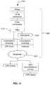
- FIG. 11illustrates a method for combined HDR broadcasting.
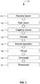
- FIG. 1shows steps of a method 101 for producing real-time HDR video.
- the method 101includes receiving 107 light through the lens of an imaging apparatus.
- One or more beamsplitterssplit 113 the light into different paths that impinge upon multiple image sensors.
- Each image sensorthen captures 125 a signal in the form of a pixel value for each pixel of the sensor.
- the sensorhas, say, 1920 ⁇ 1080 pixels, the pixel values will stream off of the sensor to a connected processing device.
- the methodincludes streaming 129 pixel values 501 from each of multiple sensors in a frame independent-manner through a pipeline 231 on a processing device 219 .
- the pipeline 231includes a kernel operation 135 that identifies saturated pixel values.
- the pixel values 501are merged 139 .
- the merged imagewill be demosaiced 145 and this produces an HDR image that can be displayed, transmitted, stored, or broadcast 151 .
- the multiple image sensorsall capture 125 images simultaneously through a single lens 311 .
- the pipeline 231 and kernel operation 135may be provided by an integrated circuit such as a field-programmable gate array or an application-specific integrated circuit.
- Each of the image sensorsmay include a color filter array 307 .
- the method 101includes demosaicing 145 the HDR image after the merging step 139 .
- the multiple image sensorspreferably capture images that are optically identical except for light level.
- a feature of the inventionis that the pixel values 501 are pipeline processed in a frame-independent manner. Sequences of pixel values 501 are streamed 129 through the processing device 219 and merged 139 without waiting to receive pixel values 501 from all pixels on the image sensors. This means that the obtaining 125 , streaming 129 , and merging 139 steps may be performed by streaming 129 the sequences of pixel values 501 through the pipeline 231 on the processing device 219 such that no location on the processing device 219 stores a complete image. Because the pixel values are streamed through the pipeline, the final HDR video signal is produced in real-time. An apparatus 201 performing steps of the method 101 thus provides the function of a real-time HDR video camera.
- Real-timemeans that HDR video from the camera may be displayed essentially simultaneously as the camera captures the scene (e.g., at the speed that the signal travels from sensor to display minus a latency no greater than a frame of film). There is no requirement for post-processing the image data and no requirement to capture, store, compare, or process entire “frames” of images.
- the outputis an HDR video signal because the method 101 and the apparatus 201 use multiple sensors at different exposure levels to capture multiple isomorphic images (i.e., identical but for light level) and merge them.
- Data from a high exposure (HE) sensorare used where portions of an image are dim and data from a mid-exposure (ME) (or lower) sensor(s) are used where portions of an image are more brightly illuminated.
- the method 101 and apparatus 201merge the HE and ME (and optionally LE) images to produce an HDR video signal.
- the method 101 and the apparatus 201identify saturated pixels in the images and replace those saturated pixels with values derived from sensors of a lower exposure.
- a first pixel value from a first pixel on one of the image sensorsis identified as saturated if it is above some specified level, for example at least 90% of a maximum possible pixel value.
- FIG. 2shows an apparatus 201 for HDR video processing.
- the apparatus 201includes a processing device 219 such as a field-programmable gate array (FPGA) or an application-specific integrated circuit (ASIC).
- a plurality of image sensors 265are coupled to the processing device 219 .
- the apparatus 201is configured to stream pixel values 501 from each of the plurality of image sensors 265 in a frame independent-manner through a pipeline 231 on the processing device 219 .
- the pipeline 231includes a kernel operation 413 that identifies saturated pixel values 501 and a merge module to merge the pixel values 501 to produce an HDR image.
- the kernel operation 413operates on pixel values 501 as they stream from each of the plurality of image sensors 265 by examining, for a given pixel on the HE sensor 213 , values from a neighborhood 601 of pixels surrounding the given pixel, finding saturated values in the neighborhood 601 of pixels, and using information from a corresponding neighborhood 601 on the ME sensor 211 to estimate a value for the given pixel.
- the apparatus 201may also include memory 221 and optionally a processor 227 (such as a general-purpose processor like an ARM microcontroller). Apparatus 201 may further include or be connected to one or more of an input-output device 239 or a display 267 .
- Memorycan include RAM or ROM and preferably includes at least one tangible, non-transitory medium.
- a processormay be any suitable processor known in the art, such as the processor sold under the trademark XEON E7 by Intel (Santa Clara, Calif.) or the processor sold under the trademark OPTERON 6200 by AMD (Sunnyvale, Calif.).
- Input/output devicesmay include a video display unit (e.g., a liquid crystal display or LED display), keys, buttons, a signal generation device (e.g., a speaker, chime, or light), a touchscreen, an accelerometer, a microphone, a cellular radio frequency antenna, port for a memory card, and a network interface device, which can be, for example, a network interface card (NIC), Wi-Fi card, or cellular modem.
- the apparatus 201may include or be connected to a storage device 241 .
- the plurality of sensorsare preferably provided in an arrangement that allows multiple sensors 265 to simultaneously receive images that are identical except for light level.
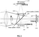
- FIG. 3shows an arrangement for the multiple sensors 265 .
- the multiple sensorspreferably include at least a high exposure (HE) sensor 213 and a middle exposure (ME) sensor 211 .
- Each image sensormay have its own color filter array 307 .
- the color filter arrays 307may operate as a Bayer filter such that each pixel receives either red, green, or blue light.
- a Bayer filterincludes a repeating grid of red, green, blue, green filters such that a sequence of pixel values streaming from the sensor corresponds to values for red, green, blue, green, red, green, blue, green, red, green, blue, green, . . . etc.
- the apparatus 201may also include or be optically connected to a lens 311 and at least one beamsplitter 301 .
- the HE sensor 213 , the ME sensor 211 , the lens 311 and the at least one beamsplitter 301are arranged to receive an incoming beam of light 305 and split the beam of light 305 into at least a first path that impinges and HE sensor 213 and a second path that impinges on the ME sensor 211 .
- the apparatus 201uses a set of partially-reflecting surfaces to split the light from a single photographic lens 311 so that it is focused onto three imaging sensors simultaneously.
- the lightis directed back through one of the beamsplitters a second time, and the three sub-images are not split into red, green, and blue but instead are optically identical except for their light levels.
- This designshown in FIG. 3 , allows the apparatus to capture HDR images using most of the light entering the camera.
- the optical splitting systemuses two uncoated, 2-micron thick plastic beamsplitters that rely on Fresnel reflections at air/plastic interfaces so their actual transmittance/reflectance (T/R) values are a function of angle. Glass is also a suitable material option.
- the first beamsplitter 301is at a 45° angle and has an approximate T/R ratio of 92/8, which means that 92% of the light from the camera lens 311 is transmitted through the first beamsplitter 301 and focused directly onto the high-exposure (HE) sensor 213 .
- the beamsplitter 301reflects 8% of the light from the lens 311 upwards (as shown in FIG. 3 ), toward the second uncoated beamsplitter 319 , which has the same optical properties as the first but is positioned at a 90° angle to the light path and has an approximate T/R ratio of 94/6.
- the HE and ME exposuresare separated by 12.2 ⁇ (3.61 stops) and the ME and LE are separated by 17.0 ⁇ (4.09 stops), which means that this configuration is designed to extend the dynamic range of the sensor by 7.7 stops.
- This beamsplitter arrangementmakes the apparatus 201 light efficient: a negligible 0.04% of the total light gathered by the lens 311 is wasted. It also allows all three sensors to “see” the same scene, so all three images are optically identical except for their light levels.
- the ME imagehas undergone an odd number of reflections and so it is flipped left-right compared to the other images, but this is fixed easily in software.
- the three sensorsindependently stream incoming pixel values directly into a pipeline that includes a synchronization module. This synchronization module can correct small phase discrepancies in data arrival times to the system from multiple sensors.
- the beamsplitter 301directs a majority of the light to the first path and a lesser amount of the light to the second path.
- the first path and the second pathimpinge on the HE sensor 213 and the ME sensor 211 , respectively, to generate images that are optically identical but for light level.
- the apparatus 201includes a low exposure (LE) sensor.
- the method 101may include receiving 107 incoming light through the lens 311 and splitting 113 the light via at least one beamsplitter 301 onto the multiple image sensors, wherein at least 95% of the incoming beam of light 305 is captured by the multiple image sensors.
- the apparatus 201(1) captures optically-aligned, multiple-exposure images simultaneously that do not need image manipulation to account for motion, (2) extends the dynamic range of available image sensors (by over 7 photographic stops in our current prototype), (3) is inexpensive to implement, (4) utilizes a single, standard camera lens 311 , and (5) efficiently uses the light from the lens 311 .
- the method 101preferably (1) combines images separated by more than 3 stops in exposure, (2) spatially blends pre-demosaiced pixel data to reduce unwanted artifacts, (3) produces HDR images that are radiometrically correct, and (4) uses the highest-fidelity (lowest quantized-noise) pixel data available.
- the apparatus 201can work with a variety of different sensor types and uses an optical architecture based on beamsplitters located between the camera lens and the sensors.
- FIG. 4shows the processing device 219 on the apparatus 201 .
- the processing device 219may be provided by one or more FPGA, ASIC, or other integrated circuit. Pixel values from the sensors stream through the pipeline 231 on the processing device 219 .
- the pipeline 231 in the processing device 219includes—in the order in which the pixel values 501 flow: a sync module 405 to synchronize the pixel values 501 as the pixel values 501 stream onto the processing device 219 from the plurality of image sensors 265 ; the kernel operation 413 ; the merge module 421 ; a demosaicing module 425 ; and a tone-mapping operator 427 .
- the pipeline 231may include one or more auxiliary module 431 such as a color-correction module; an HDR conversion module; and an HDR compression module.
- FIG. 5shows operation of the sync module 405 to synchronize the pixel values 501 as the pixel values 501 stream onto the processing device 219 from the plurality of image sensors 265 .
- HE_ 1 pixel value and ME_ 1 pixel valueare arriving at the sync module 405 approximately simultaneously.
- HE_ 2 pixel valuewill arrive late compared to ME_ 2 , and the entire sequence of LE pixel values will arrive late.
- the sync module 405can contain small line buffers that circulate the early-arriving pixel values and release them simultaneous with the corresponding later-arriving pixel values.
- the synchronized pixel valuesthen stream through the pipeline 231 to the kernel operation 413 .
- FIG. 6illustrates how the pixel values are presented to the kernel operation 413 .
- the top part of FIG. 6depicts the HE sensor 213 .
- Each squaredepicts one pixel of the sensor 213 .
- a heavy black box with a white centeris drawn to illustrate a given pixel 615 for consideration and a neighborhood 601 of pixels surrounding the given pixel 615 .
- the heavy black boxwould not actually appear on a sensor 213 (such as a CMOS cinematic camera sensor)—it is merely drawn to illustrate what the neighborhood 601 includes and to aid understanding how the neighborhood 601 appears when the sequences 621 of pixel values 501 are presented to the kernel operation 413 .
- FIG. 6shows the sequences 621 of pixel values as they stream into the kernel operation 413 after the sync module 405 .
- Pixel values 501 from the neighborhood 601 of pixels on the sensor 213are still “blacked out” to aid illustration.
- the given pixel 615 under considerationcan be spotted easily because it is surrounded on each side by two black pixels from the row of pixels on the sensor.
- There are two sequences 621one of which comes from the depicted HE sensor 213 and one of which originates at the ME sensor 211 .
- Streaming the pixel values 501 through the kernel operation 413includes examining values from a neighborhood 601 of pixels surrounding a first pixel 615 on the HE sensor 213 , finding saturated values in the neighborhood 601 of pixels, and using information from a corresponding neighborhood 613 from the ME sensor 211 to estimate a value for the first pixel 615 . This will be described in greater detail below. To accomplish this, the processing device must make comparisons between corresponding pixel values from different sensors. It may be useful to stream the pixel values through the kernel operation in a fashion that places the pixel under consideration 615 adjacent to each pixel from the neighborhood 601 as well as adjacent to each pixel from the corresponding neighborhood on another sensor.
- FIG. 7shows an approach to modeling the circuit so that the pipeline places the current pixel 615 adjacent to each of the following pixel values: a pixel value from 1 to the right on the sensor 213 , a pixel value from 2 pixels to the right on sensor 213 , a pixel value from 1 to the left, and pixel value from two to the left.
- dataflows into this portion of the pipeline and is copied four additional times. For each copy, a different and specific amount of delay is added to the main branch. The five copies all continue to flow in parallel. Thus, a simultaneous snapshot across all five copies covers the given current pixel value 615 and the other pixel values from the neighborhood 601 .
- streaming 129 the pixel values 501 through the kernel operation 413includes streaming 129 the pixel values 501 through a path 621 within the processing device 219 that momentarily places a value from the first pixel proximal to each value originating from the neighborhood 601 of pixels.
- the neighborhood comparisonsmay be used in determining whether to use a replacement value for a saturated pixel and what replacement value to use. An approach to using the neighborhood comparisons is discussed further down after a discussion of the merging.
- a replacement valuewill be used when the sequences 621 of pixel values 501 are merged 139 by the merge module 421 .
- the merging 139 stepexcludes at least some of the saturated pixel values 501 from the HDR image.
- Previous algorithms for merging HDR images from a set of LDR images with different exposurestypically do so after demosaicing the LDR images and merge data pixel-by-pixel without taking neighboring pixel information into account.
- TMOstone mapping operators
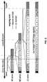
- FIG. 8illustrates an approach to merging that reduces artifacts (e.g., compared to the weighting factor used in a merging algorithm in Debevec and Malik, 1997, Recovering high dynamic range radiance maps from photographs, Proceedings of ACM SIGGRAPH 1997:369-378, incorporated by reference).
- the “HE sensor”, “ME sensor”, and “LE sensor” bars in FIG. 8present the range of scene illumination measured by the three sensors
- the systemis simplified with 4-bit sensors (as opposed to the 12-bit sensors as may be used in apparatus 201 ), which measure only 16 unique brightness values and the sensors are separated by only 1 stop (a factor of 2) in exposure. Since CMOS sensors exhibit an approximately linear relationship between incident exposure and their output value, the values from the three sensors are graphed as a linear function of incident irradiance instead of the traditional logarithmic scale.
- Methods of the inventionin contrast, use data from the higher-exposure sensor as much as possible and blend in data from the next darker sensor when near saturation.
- FIG. 8shows that the LE sensor measures the scene irradiance more coarsely than the other two sensors.
- the HE sensormay measure 4 different pixel values in a gradient before the LE sensor records a single increment.
- there is always some small amount of noise in the pixel valuesand an error of ⁇ 1 in the LE sensor spans a 12 value range in the HE sensor for this example.
- Debevec and Malik's algorithmblends these values together, the method 101 and apparatus 201 use pixel values from only the longest-exposure sensor (which is less noisy) wherever possible, and blend in the next darker exposure when pixels approach saturation.
- the method 101 and apparatus 201not only examine individual pixels when merging the LDR images, but also take into account neighboring pixels 601 (see FIG. 6 ) that might provide additional information to help in the de-noising process.
- One aspect of merging 139 according to the inventionis to use pixel data exclusively from the brightest, most well-exposed sensor possible. Therefore, pixels from the HE image are used as much as possible, and pixels in the ME image are only used if the HE pixel is close to saturation. If the corresponding ME pixel is below the saturation level, it is multiplied by a factor that adjusts it in relation to the HE pixel based on the camera's response curve, given that the ME pixel receives 12.2 ⁇ less irradiance than the HE pixel.
- FIG. 9shows a camera response curve 901 used to obtain a factor for adjusting a pixel value.
- a camera response curve 901used to obtain a factor for adjusting a pixel value.
- the method 101 and apparatus 201transition from one sensor to the next by spatially blending pixel values between the two sensors. To do this, the method 101 and apparatus 201 scan a neighborhood 601 around the pixel 615 being evaluated (see FIG. 6 ). If any neighboring pixels in this region are saturated, then the pixel under consideration may be subject to pixel crosstalk or leakage, and the method 101 and apparatus 201 will estimate a value for the pixel based on its neighbors in the neighborhood 601 .
- the method 101 and apparatus 201perform merging 139 prior to demosaicing 145 the individual Bayer color filter array images because demosaicing can corrupt colors in saturated regions. For example, a bright orange section of a scene might have red pixels that are saturated while the green and blue pixels are not. If the image is demosaiced before being merged into HDR, the demosaiced orange color will be computed from saturated red-pixel data and non-saturated green/blue-pixel data. As a result, the hue of the orange section will be incorrectly reproduced. To avoid these artifacts, the method 101 and apparatus 201 perform HDR-merging prior to demosaicing.
- the method 101 and apparatus 201work with pixel values instead of irradiance.
- the method 101 and apparatus 201match the irradiance levels of the HE, ME, and LE sensors using the appropriate beamsplitter transmittance values for each pixel color, since these change slightly as a function of wavelength.
- the method 101 and apparatus 201use different values to match each of the color channels, for simplicity the process is explained with average values.
- a pixel valueis converted through the camera response curve 901 , where the resulting irradiance is adjusted by the exposure level ratio (average of 12.2 ⁇ for HE/ME), and this new irradiance value is converted back through the camera response curve 901 to a new pixel value.
- FIG. 9shows the 3-step HDR conversion process to match the irradiance levels of the HE, ME, and LE sensors.
- the HDR conversion processmay be done for all HE pixel values (from 1 through 4096, for example), to arrive at a pixel-ratio curve, which gives the scaling factor for converting each ME pixel's value to the corresponding pixel value on the HE sensor for the same irradiance.
- pixel-ratio curvesare calculated for each color (R,G,B) in the Bayer pattern.
- a simple multipliermay be used, or the pixel-ratio curves may be used as lookup tables (LUTs), to convert HE pixel values less than 4096 into ME pixel values, or vice versa.
- LUTslookup tables
- the camera response curve 901can be measured by taking a set of bracketed exposures and solving for a monotonically-increasing function that relates exposure to pixel value (to within a scale constant in the linear domain).
- FIG. 9shows the curve computed from the raw camera data, although a curve computed from a linear best-fit could also be used.
- FIG. 9gives a camera response curve that shows how the camera converts scene irradiance into pixel values.
- the HE pixel value (1)is first converted to a scene irradiance (2), which is next divided by our HE/ME attenuation ratio of 12.2.
- This new irradiance value (3)is converted through the camera response curve into the expected ME pixel value (4).
- this graphis approximately linear, it is not perfectly so because it is computed from the raw data, without significant smoothing or applying a linear fit. With the irradiance levels of the three images matched, the merging 139 may be performed.
- merging 139two registered LDR images (one high-exposure image IHE and a second medium-exposure image IME) are to be merged 139 into an HDR image IHDR.
- the merging 139starts with the information in the high-exposure image IHE and then combines in data from the next darker-exposure image IME, as needed.
- the method 101 and apparatus 201work on each pixel location (x, y) by looking at the information from the surrounding (2k+1) ⁇ (2k+1) pixel neighborhood 601 , denoted as N(x,y).
- the merging 139includes a specific operation for each of the four cases for the pixel 615 on sensor 213 and its neighborhood 601 (see FIG. 6 ):
- Case 2The pixel 615 is not saturated, but the neighborhood 601 has 1 or more saturated pixels, so blend between the pixel value at IHE(x, y) and the one at the next darker-exposure IME(x, y) depending on the amount of saturation present in the neighborhood.
- Case 3The pixel 615 is saturated but the neighborhood 601 has 1 or more non-saturated pixels, which can be used to better estimate a value for IHE(x,y): calculate the ratios of pixel values in the ME image between the unsaturated pixels in the neighborhood and the center pixel, and use this map of ME ratios to estimate the actual value of the saturated pixel under consideration.
- HDR imagethat can be demosaiced 145 and converted from pixel values to irradiance using a camera response curve similar to that of FIG. 9 accounting for all 3 color channels.
- the final HDR full-color imagemay then be tone mapped (e.g., with commercial software packages such as FDRTools, HDR Expose, Photomatix, etc.)
- the apparatus 201may be implemented using three Silicon Imaging SI-1920HD high-end cinema CMOS sensors mounted in a camera body. Those sensors have 1920 ⁇ 1080 pixels (5 microns square) with a standard Bayer color filter array, and can measure a dynamic range of around 10 stops (excluding noise). The sensors are aligned by aiming the camera at small pinhole light sources, locking down the HE sensor and then adjusting setscrews to align the ME and LE sensors.
- the camera bodymay include a Has selblad lens mount to allow the use of high-performance, interchangeable commercial lenses.
- the apparatusmay include uncoated pellicle beamsplitters, such as the ones sold by Edmund Optics [part number NT39-482].
- the apparatus 201may perform the steps of the method 101 .
- the multiple image sensorsinclude at least a high exposure (HE) sensor 213 and a middle exposure (ME) sensor 211 , and the merging includes using HE pixel values 501 that are not saturated and ME pixel values 501 corresponding to the saturated pixel values.
- HEhigh exposure
- MEmiddle exposure
- the multiple sensorsmay further include a low exposure (LE) sensor 261 , and the method 101 may include identifying saturated pixel values 501 originating from both the HE sensor 213 and the ME sensor 211 . Because the pixel values stream through a pipeline, it is possible that at least some of the saturated pixel values 501 are identified before receiving values from all pixels of the multiple image sensors at the processing device 219 and the method 101 may include beginning to merge 139 portions of the sequences while still streaming 129 later-arriving pixel values 501 through the kernel operation 413 .
- LTElow exposure
- optical componentssuch as beamsplitters, lenses, or filters—even if labeled “spectrally neutral”—may have slight wavelength-dependent differences in the amounts of light transmitted. That is, each image sensor may be said to have its own “color correction space” whereby images from that sensor need to be corrected out of that color correction space to true color.
- the optical systemcan be calibrated (e.g., by taking a picture of a calibration card) and a color correction matrix can be stored for each image sensor.
- the HDR video pipelinecan then perform the counter-intuitive step of adjusting the pixel values from one sensor towards the color correction of another sensor—which may in some cases involve nudging the colors away from true color.
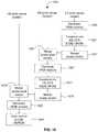
- FIG. 10shows a color correction processes 1001 by which the HDR pipeline can correct for differences in spectral characteristics of each of the multiple sensors.
- the pipeline 231includes modules for color correction. The steps of a color correction process may be applied at multiple locations along the pipeline, so the color correction may be implemented via specific modules at different locations on the FPGA. Taken together, those modules may be referred to as a color correction module that implements the color correction process 1001 .
- the color correction process 1001converts one sensor's data from its color correction space to the color correction space of another sensor, before merging the images from the two sensors.
- the merged image datacan then be converted to the color correction space of a third sensor, before being combined with the image data from that third sensor.
- the processmay be repeated for as many sensors as desired. After all sensors' images have been combined, the final combined image may be demosaiced 145 and then may be color corrected to truth.
- the color correction process 1001allows images from multiple sensors to be merged, in stages where two images are merged at a time, in a way that preserves color information from one sensor to the next. For example purposes, in FIG. 10 , the HE pixel values from the HE sensor are merged with the ME pixel values from the ME sensor. The result of merging is then merged with the LE pixel values from the LE sensor.
- the basic principle guiding the color correction process 1001is to first convert a dark image to the color correction space of the next brightest image, and then to merge the two “non-demosaiced” (or Color Filter Array [CFA] Bayer-patterned) images together.
- the color correction process 1001for an apparatus 201 with an ME sensor, an LE sensor, and an SE sensor, includes three general phases: an SE color correction space (CCS) phase, ME color correction space phase, and LE color correction space phase.
- the color correction processfirst begins with the SE color correction space phase, which comprises first demosaicing 1045 the LE pixel values and then transforming 1051 the resulting vectors into the color correction space of the ME image.
- the demosaicing process 1045yields a full-color RGB vector value for each pixel.
- the LE image datais next transformed 1045 into the ME color correction space.
- the purposeis to match the color of the LE pixels (now described by RGB vectors) to the color of the ME array (with all of the ME array's color imperfections).
- the LE RGB vectorsare transformed 1051 by a color correction matrix.
- Equations 1-3show how to use the color correction matrices to correct the color values for the HE, ME, and LE sensors, respectively.
- Equation 1shows how to use the color correction matrix to correct the color values of the HE sensor, where the 3 ⁇ 3 matrix coefficients, including values A 1 -A 9 , represent coefficients selected to strengthen or weaken the pixel value, and an RGB matrix (RLE, GLE, and BLE) represents the demosaiced RGB output signal from the LE sensor.
- the 3 ⁇ 3 matrix coefficientscan be derived by comparing the demosaiced output against expected (or so-called “truth”) values.
- the 3 ⁇ 3 matrix coefficientscan be derived by least-squares polynomial modeling between the demosaiced RGB output values and reference values from a reference color chart (e.g., a Macbeth chart).
- Equation 2shows how to use the color correction matrix to correct the color values of the ME sensor, where the RGB matrix (RME, GME, and BME) represents the demosaiced RGB output signal from the ME sensor
- Equation 3shows how to use the color correction matrix to correct the color values of the SE sensor, where the RGB matrix (RME, GME, and BME) represents the demosaiced RGB output values from the SE sensor.
- the color correction matrices from one or more sensorscan be used. This process may be referred to as converting between color correction spaces or calibrating color correction spaces. Neither the first color correction space nor the second color correction space accurately reflects the true color of the captured image. The first and the second color correction space both have inaccuracies, and those inaccuracies are, in general, different from one another. Thus RGB values from each sensor must be multiplied by a unique color correction matrix for those RUB values to appear as true colors.
- the present inventionincludes a method for converting an image from the LE sensor's color correction space to the ME sensor's color correction space and is illustrated in Equation 4 below:
- Equation 4the LE sensor's pixel values (R, G, B) are multiplied by the LE sensor's correction matrix. [C], and then multiplied by the inverse of the MME sensor's correction matrix, [B]. The result is a set of pixel values (R, G, B) that are in the ME sensor's color correction space.
- Methods of the inventionallow matching of the color correction space of the second sensor to the color correction space of the first sensor so that the images from the two sensors may be accurately combined, or merged.
- the method for applying all the inaccuracies of the second color correction space to the first color correction space, prior to combining images from the two into an HDR imageis previously unknown.
- Typical methods for combining data from multiple CFA sensorsrely on color-correcting each sensor's data to the “truth” values measured from a calibrated color card, prior to combining the images. This is problematic in an HDR system, where it is known that the brighter sensor's image will have significant portions that are saturated, which saturated portions should actually have been utilized from the darker sensor's image when combining.
- Color correcting an image that has color information based on saturated pixelswill cause colors to be misidentified. Therefore, in an HDR system, color-correcting the brighter image (for example, to “truth” color values), prior to combining images, will lead to colors being misidentified because of the use of saturated pixel data in creating colors from a mosaic-patterned image. For this reason, we specify that (1) the darker image have its color information transformed to match the color space of the brighter image, (2) this transformed darker image be combined with the brighter image, and then (3) the final combined image be color-transformed to “truth” color values.
- the solution provided in the present inventionavoids this saturated-pixel color misidentification problem by performing the steps of [(a) demosaic 1045 , (b) color correct 1051 & (c) mosaic 1057 ] data from the darker sensor, thereby ensuring all data is accurately returned to its non-demosaiced state prior to the step of merging the darker sensor's data with the brighter sensor's data.
- the present inventionmatches the color correction spaces of the two sensors.
- This transformationensures that the two images (from the first and second color correction space sensors) can be accurately merged, pixel-for-pixel, in non-demosaiced format. It may at first seem counterintuitive to change the color correction space of one sensor to match the color correction space of a second sensor, especially when the second sensor's color correction space is known to differ from the “true” color correction space.
- the color correction process 1001uses matrices that may themselves be implemented as kernels in the pipeline 231 on the processing device 219 . Thus the color correction process 1001 is compatible with an HDR pipeline workflow because the kernels are applied as they receive the pixel values.
- the transformed valuesare mosaiced 1057 (i.e., the demosaicing process is reversed).
- the transformed scalar pixel valuesare now comparable with the Bayer-patterned scalar ME pixel values detected by the ME sensor, and the process 1001 includes merging 1061 of ME and HE non-demosaiced (i.e., scalar) sensor data.
- the merged non-demosaiced image within the ME color correction spaceis then demosaiced 1067 .
- This demosaicing 1064is similar to the demosaicing 1045 described above, except the CFA pixel values undergoing the demosaicing process are now associated with the ME color correction space.
- the demosaicing 1067produces RGB vectors in the ME color space. Those RGB vectors are transformed 1071 into the HE color space while also being color corrected ([B][A] ⁇ 1[RGB]). Equation 2 shows how to use the color correction matrix to correct the color values of the ME sensor.
- the color corrected ME informationis transformed 1071 from the ME color correction space to the HE color correction space by multiplying the ME color correction matrix by the inverse of the SE color correction matrix.
- the transformed vectorsare mosaiced 1075 (i.e., the demosaicing process is reversed). This allows the transformed ME CFA Bayer-patterned pixel values to merge 1079 with the HE pixel values detected by the HE sensor.
- the transformed color information detected by the HE and ME sensorsis now calibrated to match the color information detected by the HE sensor.
- This newly merged color value data setnow represents color values within the HE color correction space 205 .
- FIG. 11illustrates a method 1301 for combined broadcasting of high dynamic range (HDR) video with standard dynamic range (SDR) video.
- the method 1301provides for streaming HDR and SDR video.
- the method 1301includes detecting 125 —using an array of sensors 165 —information representing a series of images, processing 1309 the information, and transmitting 1321 the information for HDR and LDR display with less than one frame of delay between detection and transmission.
- the pipelineAfter the color processing and tone-mapping, the pipeline has produced an HDR video signal.
- What flows from the subtraction moduleis a pair of streams—the SDR video signal and the residual signal.
- the HDR signalmay be subject to HDR compression by a suitable operation (e.g., JPEG or similar).
- the pair of streamsincludes the 8-bit SDR signal and the compressed HDR residual signal, which provides for HDR display.
- This dual signalis broadcast over a communication network and may in-fact be broadcast over television networks, cellular networks, or the Internet.
- a device that receives the signaldisplays the video according to the capacity of that device.
- An SDR display devicewill “see” the 8-bit SDR signal and display a video at a dynamic range that is standard, which signal has also had a certain TMO applied to it.
- An HDR display devicewill decompress the residuals and combine the dual streams into an HDR signal and display HDR video.
- the method 1301 and the apparatus 201may be used for real-time HDR video capture as well as for the simultaneous delivery of HDR and SDR output in a single transmission.
- the processing 1309may include the workflow from the processing device 219 to video (broadcast) output.
- the method 1301 and the apparatus 201provide for real-time processing and complementary HDR/SDR display using features described herein such as multiple sensors all obtaining an isomorphic image through a single lens and streaming the resulting pixel values through a pipeline to replace saturated pixels in a merged HDR video signal.
- the method 101 and the apparatus 201each captures video information using an array of sensors, processes that video information in real-time, and transmits the video information in real-time in a HDR and LDR compatible format.
Landscapes
- Engineering & Computer Science (AREA)
- Multimedia (AREA)
- Signal Processing (AREA)
- Physics & Mathematics (AREA)
- General Physics & Mathematics (AREA)
- Theoretical Computer Science (AREA)
- General Health & Medical Sciences (AREA)
- Health & Medical Sciences (AREA)
- Biomedical Technology (AREA)
- Spectroscopy & Molecular Physics (AREA)
- Optics & Photonics (AREA)
- Computer Vision & Pattern Recognition (AREA)
- Human Computer Interaction (AREA)
- Color Television Image Signal Generators (AREA)
- Studio Devices (AREA)
- Two-Way Televisions, Distribution Of Moving Picture Or The Like (AREA)
- Processing Of Color Television Signals (AREA)
Abstract
Description
Claims (14)
Priority Applications (5)
| Application Number | Priority Date | Filing Date | Title |
|---|---|---|---|
| US16/376,146US10742847B2 (en) | 2016-02-12 | 2019-04-05 | Devices and methods for high dynamic range video |
| US16/988,853US11463605B2 (en) | 2016-02-12 | 2020-08-10 | Devices and methods for high dynamic range video |
| US17/958,781US11805218B2 (en) | 2016-02-12 | 2022-10-03 | Devices and methods for high dynamic range video |
| US18/477,824US12212728B2 (en) | 2016-02-12 | 2023-09-29 | Devices and methods for high dynamic range video |
| US19/038,175US20250247491A1 (en) | 2016-02-12 | 2025-01-27 | Devices and methods for high dynamic range video |
Applications Claiming Priority (3)
| Application Number | Priority Date | Filing Date | Title |
|---|---|---|---|
| US201662294820P | 2016-02-12 | 2016-02-12 | |
| US15/169,006US10257393B2 (en) | 2016-02-12 | 2016-05-31 | Devices and methods for high dynamic range video |
| US16/376,146US10742847B2 (en) | 2016-02-12 | 2019-04-05 | Devices and methods for high dynamic range video |
Related Parent Applications (1)
| Application Number | Title | Priority Date | Filing Date |
|---|---|---|---|
| US15/169,006ContinuationUS10257393B2 (en) | 2016-02-12 | 2016-05-31 | Devices and methods for high dynamic range video |
Related Child Applications (1)
| Application Number | Title | Priority Date | Filing Date |
|---|---|---|---|
| US16/988,853ContinuationUS11463605B2 (en) | 2016-02-12 | 2020-08-10 | Devices and methods for high dynamic range video |
Publications (2)
| Publication Number | Publication Date |
|---|---|
| US20190238725A1 US20190238725A1 (en) | 2019-08-01 |
| US10742847B2true US10742847B2 (en) | 2020-08-11 |
Family
ID=59559836
Family Applications (14)
| Application Number | Title | Priority Date | Filing Date |
|---|---|---|---|
| US15/169,012ActiveUS10257394B2 (en) | 2016-02-12 | 2016-05-31 | Combined HDR/LDR video streaming |
| US15/169,006Active2037-04-26US10257393B2 (en) | 2016-02-12 | 2016-05-31 | Devices and methods for high dynamic range video |
| US15/427,767ActiveUS9948829B2 (en) | 2016-02-12 | 2017-02-08 | Color matching across multiple sensors in an optical system |
| US15/914,329ActiveUS10200569B2 (en) | 2016-02-12 | 2018-03-07 | Color matching across multiple sensors in an optical system |
| US16/265,285ActiveUS10536612B2 (en) | 2016-02-12 | 2019-02-01 | Color matching across multiple sensors in an optical system |
| US16/376,146ActiveUS10742847B2 (en) | 2016-02-12 | 2019-04-05 | Devices and methods for high dynamic range video |
| US16/376,149ActiveUS10805505B2 (en) | 2016-02-12 | 2019-04-05 | Combined HDR/LDR video streaming |
| US16/988,853Active2036-10-26US11463605B2 (en) | 2016-02-12 | 2020-08-10 | Devices and methods for high dynamic range video |
| US17/065,789ActiveUS11368604B2 (en) | 2016-02-12 | 2020-10-08 | Combined HDR/LDR video streaming |
| US17/842,157ActiveUS11785170B2 (en) | 2016-02-12 | 2022-06-16 | Combined HDR/LDR video streaming |
| US17/958,781ActiveUS11805218B2 (en) | 2016-02-12 | 2022-10-03 | Devices and methods for high dynamic range video |
| US18/450,569ActiveUS12250357B2 (en) | 2016-02-12 | 2023-08-16 | Combined HDR/LDR video streaming |
| US18/477,824ActiveUS12212728B2 (en) | 2016-02-12 | 2023-09-29 | Devices and methods for high dynamic range video |
| US19/038,175PendingUS20250247491A1 (en) | 2016-02-12 | 2025-01-27 | Devices and methods for high dynamic range video |
Family Applications Before (5)
| Application Number | Title | Priority Date | Filing Date |
|---|---|---|---|
| US15/169,012ActiveUS10257394B2 (en) | 2016-02-12 | 2016-05-31 | Combined HDR/LDR video streaming |
| US15/169,006Active2037-04-26US10257393B2 (en) | 2016-02-12 | 2016-05-31 | Devices and methods for high dynamic range video |
| US15/427,767ActiveUS9948829B2 (en) | 2016-02-12 | 2017-02-08 | Color matching across multiple sensors in an optical system |
| US15/914,329ActiveUS10200569B2 (en) | 2016-02-12 | 2018-03-07 | Color matching across multiple sensors in an optical system |
| US16/265,285ActiveUS10536612B2 (en) | 2016-02-12 | 2019-02-01 | Color matching across multiple sensors in an optical system |
Family Applications After (8)
| Application Number | Title | Priority Date | Filing Date |
|---|---|---|---|
| US16/376,149ActiveUS10805505B2 (en) | 2016-02-12 | 2019-04-05 | Combined HDR/LDR video streaming |
| US16/988,853Active2036-10-26US11463605B2 (en) | 2016-02-12 | 2020-08-10 | Devices and methods for high dynamic range video |
| US17/065,789ActiveUS11368604B2 (en) | 2016-02-12 | 2020-10-08 | Combined HDR/LDR video streaming |
| US17/842,157ActiveUS11785170B2 (en) | 2016-02-12 | 2022-06-16 | Combined HDR/LDR video streaming |
| US17/958,781ActiveUS11805218B2 (en) | 2016-02-12 | 2022-10-03 | Devices and methods for high dynamic range video |
| US18/450,569ActiveUS12250357B2 (en) | 2016-02-12 | 2023-08-16 | Combined HDR/LDR video streaming |
| US18/477,824ActiveUS12212728B2 (en) | 2016-02-12 | 2023-09-29 | Devices and methods for high dynamic range video |
| US19/038,175PendingUS20250247491A1 (en) | 2016-02-12 | 2025-01-27 | Devices and methods for high dynamic range video |
Country Status (6)
| Country | Link |
|---|---|
| US (14) | US10257394B2 (en) |
| EP (2) | EP3414539B1 (en) |
| JP (2) | JP6928388B2 (en) |
| AU (1) | AU2017217929B2 (en) |
| CA (2) | CA3016421A1 (en) |
| WO (2) | WO2017139363A1 (en) |
Cited By (4)
| Publication number | Priority date | Publication date | Assignee | Title |
|---|---|---|---|---|
| US11463605B2 (en)* | 2016-02-12 | 2022-10-04 | Contrast, Inc. | Devices and methods for high dynamic range video |
| US11910099B2 (en) | 2016-08-09 | 2024-02-20 | Contrast, Inc. | Real-time HDR video for vehicle control |
| US11985316B2 (en) | 2018-06-04 | 2024-05-14 | Contrast, Inc. | Compressed high dynamic range video |
| US12309427B2 (en) | 2018-08-14 | 2025-05-20 | Contrast, Inc. | Image compression |
Families Citing this family (17)
| Publication number | Priority date | Publication date | Assignee | Title |
|---|---|---|---|---|
| EP3142002A1 (en) | 2015-09-09 | 2017-03-15 | Red.Com, Inc. | Motion video output for multiple displays |
| US9871965B2 (en)* | 2016-02-03 | 2018-01-16 | Texas Instruments Incorporated | Image processing for wide dynamic range (WDR) sensor data |
| US10264196B2 (en) | 2016-02-12 | 2019-04-16 | Contrast, Inc. | Systems and methods for HDR video capture with a mobile device |
| WO2019014057A1 (en) | 2017-07-10 | 2019-01-17 | Contrast, Inc. | STEREOSCOPIC CAMERA |
| CN108038835B (en)* | 2017-11-27 | 2021-07-13 | 杭州电子科技大学 | A saliency-driven method for automatic generation of image important region mosaic |
| CN113691738B (en) | 2018-06-07 | 2023-04-18 | 杜比实验室特许公司 | Generating HDR images from single shot HDR color image sensors |
| WO2020036955A1 (en) | 2018-08-14 | 2020-02-20 | Contrast, Inc. | Image processing noise reduction |
| BR112021022458A2 (en) | 2019-05-10 | 2021-12-28 | Univ California | Modified pluripotent cells or a cell derived therefrom, method of transplanting a cell, method of treating a disease in a patient in need of transplanted cells, method of generating a modified pluripotent cell, method of generating a hypoimmunogenic pluripotent cell, and method of transplantation of a hypoimmunogenic pluripotent cell (hyp) or cell derived therefrom |
| WO2021026063A1 (en) | 2019-08-02 | 2021-02-11 | Contrast, Inc. | Code-independent graph technology |
| CN110636198A (en)* | 2019-10-15 | 2019-12-31 | 重庆金山医疗技术研究院有限公司 | Imaging method and device and endoscope equipment |
| US10819915B1 (en) | 2019-10-17 | 2020-10-27 | Horiba Instruments Incorporated | Apparatus and method generating high dynamic range video |
| US11333829B2 (en)* | 2019-11-22 | 2022-05-17 | Karl Storz Imaging, Inc. | Medical imaging device with split image on common image sensor |
| CN114205487A (en)* | 2020-08-28 | 2022-03-18 | 超威半导体公司 | Content-adaptive lens shading correction method and device |
| US11587213B1 (en) | 2021-11-05 | 2023-02-21 | GM Cruise Holdings LLC. | Preserving dynamic range in images |
| DE102022114615A1 (en) | 2022-06-10 | 2023-12-21 | Carl Zeiss Ag | Digital long-range optical device, method for operating a digital long-range optical device and camera system |
| US20240095961A1 (en)* | 2022-09-20 | 2024-03-21 | GM Global Technology Operations LLC | Interpreting color in an environment |
| WO2024225170A1 (en)* | 2023-04-26 | 2024-10-31 | Sony Semiconductor Solutions Corporation | Information processing device, information processing method, program, image processing device, and image processing method |
Citations (223)
| Publication number | Priority date | Publication date | Assignee | Title |
|---|---|---|---|---|
| US2560351A (en) | 1946-12-14 | 1951-07-10 | Rca Corp | Simultaneous color television |
| US2642487A (en) | 1947-02-28 | 1953-06-16 | Rca Corp | Component color separator |
| US2971051A (en) | 1958-12-08 | 1961-02-07 | Frank G Back | Varifocal, long back-focal lens for color television |
| US3202039A (en) | 1960-08-02 | 1965-08-24 | Philips Corp | Optical system for a color television camera |
| US3381084A (en) | 1964-06-01 | 1968-04-30 | Mannie Feigenbaum | Color television camera optical system |
| US3474451A (en) | 1967-04-10 | 1969-10-21 | William E Abel | Loop antenna circuit coupling multiple transmitters |
| US3601480A (en) | 1968-07-10 | 1971-08-24 | Physics Int Co | Optical tunnel high-speed camera system |
| US3653748A (en) | 1968-12-26 | 1972-04-04 | Int Video Corp | Color divider for color video cameras |
| US3659918A (en) | 1970-03-24 | 1972-05-02 | Philips Corp | Color separating prism system |
| US3668304A (en) | 1970-06-29 | 1972-06-06 | Bell Telephone Labor Inc | Single pickup tube color television camera |
| US3720146A (en) | 1972-03-15 | 1973-03-13 | Spectral Data Corp | Multispectral camera |
| US3802763A (en) | 1971-09-01 | 1974-04-09 | Rank Organisation Ltd | Beam splitting prisms |
| US3945034A (en) | 1973-04-26 | 1976-03-16 | Canon Kabushiki Kaisha | Optical system for a color television camera |
| US4009941A (en) | 1974-01-07 | 1977-03-01 | U.S. Philips Corporation | Color-separating prism arrangement of which some surfaces adjoin dichroic layers |
| US4072405A (en) | 1974-06-13 | 1978-02-07 | Tokina Optical Co., Ltd. | Prism system for use in tricolor separation |
| US4084180A (en) | 1975-10-09 | 1978-04-11 | U.S. Philips Corporation | Color splitting prism assembly |
| JPS5393026A (en) | 1977-01-27 | 1978-08-15 | Sony Corp | Color separation optical apparatus |
| JPS53124028A (en) | 1977-04-05 | 1978-10-30 | Sony Corp | Solid state image pickup device |
| US4134683A (en) | 1976-03-05 | 1979-01-16 | The United States Of America As Represented By The Administrator Of The National Aeronautics And Space Administration | Multispectral imaging and analysis system |
| US4268119A (en) | 1979-01-22 | 1981-05-19 | Bell & Howell Company | Color-separating optical system |
| US4395234A (en) | 1977-09-16 | 1983-07-26 | Farrand Optical Co., Inc. | Optical scanning probe with multiple outputs |
| US4396188A (en) | 1981-07-15 | 1983-08-02 | Dreissigacker Peter D | Stationary rowing unit |
| US4486069A (en) | 1981-07-01 | 1984-12-04 | Barr & Stroud Limited | Afocal telescopes |
| JPS60213178A (en) | 1984-04-06 | 1985-10-25 | Olympus Optical Co Ltd | Image pickup device |
| US4555163A (en) | 1983-09-22 | 1985-11-26 | Rca Corporation | Complementary color splitting filters used in a color camera |
| US4584606A (en) | 1983-09-01 | 1986-04-22 | Olympus Optical Co., Ltd. | Image pickup means |
| US4743011A (en) | 1986-07-07 | 1988-05-10 | Calvin Coffey | Exercise rowing machine |
| JPS63160489A (en) | 1986-12-24 | 1988-07-04 | Mitsubishi Electric Corp | solid-state imaging device |
| US4786813A (en) | 1984-10-22 | 1988-11-22 | Hightech Network Sci Ab | Fluorescence imaging system |
| US4805037A (en) | 1987-10-15 | 1989-02-14 | Eastman Kodak Company | Image recording system |
| US4916529A (en) | 1986-11-14 | 1990-04-10 | Canon Kabushiki Kaisha | Imaging device utilizing solid-state image sensors combined with a beam-splitting prism |
| US4933751A (en) | 1987-09-09 | 1990-06-12 | Victor Company Of Japan, Ltd. | Tri-color separating optical system |
| US5024530A (en) | 1989-12-26 | 1991-06-18 | Lockheed Missiles & Space Company, Inc. | Multichannel telecentric filtered imager |
| US5093563A (en) | 1987-02-05 | 1992-03-03 | Hughes Aircraft Company | Electronically phased detector arrays for optical imaging |
| US5092581A (en) | 1990-07-02 | 1992-03-03 | Michael Koz | Rowing exercise apparatus |
| JPH0468876A (en) | 1990-07-05 | 1992-03-04 | Kinki Univ | Video photographing device for measuring high flow velocity place |
| EP0484802A2 (en) | 1990-11-06 | 1992-05-13 | Biophotonics, Inc. | Optical beam-splitting system for the generation of a plurality of real images |
| US5134468A (en) | 1989-02-21 | 1992-07-28 | Canon Kabushiki Kaisha | Optical apparatus for varying the lengths of optical path of color component light beams |
| US5153621A (en) | 1991-10-31 | 1992-10-06 | Nview Corporation | Optical system for projecting multiple images in adjoining relation without illuminance discontinuities |
| US5155623A (en) | 1988-09-23 | 1992-10-13 | At&T Bell Laboratories | Arrangement for imaging multiple arrays of light beams |
| JPH0564070A (en) | 1991-08-30 | 1993-03-12 | Fuji Photo Film Co Ltd | Device and method for image pickup and unit and method for image processing |
| US5194959A (en) | 1989-12-21 | 1993-03-16 | Ricoh Company, Ltd. and Nippon Telegraph and Telephone Corporation | Image forming apparatus for forming image corresponding to subject, by dividing optical image corresponding to the subject into plural adjacent optical image parts |
| US5272518A (en) | 1990-12-17 | 1993-12-21 | Hewlett-Packard Company | Colorimeter and calibration system |
| JPH06335006A (en) | 1993-05-19 | 1994-12-02 | Matsushita Electric Ind Co Ltd | Solid-state image pickup device |
| US5386316A (en) | 1991-05-02 | 1995-01-31 | Hughes Aircraft Company | Optical systems having multiple simultaneous functions |
| JPH07107346A (en) | 1993-09-29 | 1995-04-21 | New Kurieishiyon:Kk | Inspection device |
| JPH08220585A (en) | 1995-02-13 | 1996-08-30 | Nikon Corp | Electronic camera |
| US5642191A (en) | 1995-07-20 | 1997-06-24 | Lockheed Missiles & Space Company, Inc. | Multi-channel imaging spectrophotometer |
| US5707322A (en) | 1994-02-28 | 1998-01-13 | Concept Ii, Inc. | Exercise machine |
| US5729011A (en) | 1995-02-24 | 1998-03-17 | Olympus Optical Co., Ltd. | Spectroscopic apparatus and spectroscopic image recording apparatus |
| US5734507A (en) | 1993-11-29 | 1998-03-31 | Hadland Photonics Limited | Optical beam splitter and electronic high speed camera incorporating such a beam splitter |
| US5801773A (en) | 1993-10-29 | 1998-09-01 | Canon Kabushiki Kaisha | Image data processing apparatus for processing combined image signals in order to extend dynamic range |
| US5835278A (en) | 1990-11-06 | 1998-11-10 | Rubin; Leoind Borisovich | Optical system for partitioning a real image |
| US5856466A (en) | 1990-01-11 | 1999-01-05 | Isis Pharmaceuticals, Inc. | Process for the preparation of 2'-O-alkyl purine phosphoramidites |
| US5881043A (en) | 1997-03-19 | 1999-03-09 | Fujitsu Limited | Optical pickup with a first detector to receive reflected data component signal and a second detector to receive reflected other component signal |
| US5900942A (en) | 1997-09-26 | 1999-05-04 | The United States Of America As Represented By Administrator Of National Aeronautics And Space Administration | Multi spectral imaging system |
| JPH11127441A (en) | 1997-10-21 | 1999-05-11 | Tokyo Electron Ind Co Ltd | Imaging device |
| US5905490A (en) | 1996-02-26 | 1999-05-18 | Seiko Epson Corporation | Generating color-correction look-up-table addresses by multi-level half-toning |
| US5926283A (en) | 1997-07-12 | 1999-07-20 | Optical Insights, Llc | Multi-spectral two dimensional imaging spectrometer |
| US5929908A (en) | 1995-02-03 | 1999-07-27 | Canon Kabushiki Kaisha | Image sensing apparatus which performs dynamic range expansion and image sensing method for dynamic range expansion |
| US6011876A (en) | 1997-02-26 | 2000-01-04 | Raytheon Company | System and method for converting an incoming image into electronic form |
| JP2000019407A (en) | 1998-07-06 | 2000-01-21 | Olympus Optical Co Ltd | Image-formation optical system |
| JP2000338313A (en) | 1999-05-26 | 2000-12-08 | Sony Corp | Color resolving prism |
| US6215597B1 (en) | 1999-11-17 | 2001-04-10 | Duncan Technologies, Inc. | Apparatus for forming a plurality of subimages having different characteristics |
| JP2001136434A (en) | 1999-11-09 | 2001-05-18 | Ricoh Co Ltd | Imaging device |
| US20020014577A1 (en) | 1998-07-08 | 2002-02-07 | Ppt Vision, Inc. | Circuit for machine-vision system |
| US6392687B1 (en) | 1997-05-08 | 2002-05-21 | Be Here Corporation | Method and apparatus for implementing a panoptic camera system |
| JP2002165108A (en) | 2000-11-28 | 2002-06-07 | Fuji Photo Film Co Ltd | Image acquisition device |
| US20020089765A1 (en) | 1995-11-30 | 2002-07-11 | Nalwa Vishvjit Singh | Panoramic viewing system with a composite field of view |
| US20030007254A1 (en) | 2001-07-05 | 2003-01-09 | Science & Engineering Associates, Inc. | Multiple imaging system |
| US20030016334A1 (en) | 2001-06-11 | 2003-01-23 | Weber Michael F. | Polarizing beam splitter |
| JP2003035881A (en) | 2001-07-25 | 2003-02-07 | Minolta Co Ltd | Image display device |
| US20030048493A1 (en) | 2001-09-10 | 2003-03-13 | Pontifex Brian Decoursey | Two sensor quantitative low-light color camera |
| US20030072011A1 (en) | 2001-10-09 | 2003-04-17 | Shirley Lyle G. | Method and apparatus for combining views in three-dimensional surface profiling |
| US6646716B1 (en) | 2000-07-27 | 2003-11-11 | Eastman Kodak Company | Method and apparatus for printing multiple simultaneous images onto a photosensitive media |
| US6674487B1 (en) | 2000-03-31 | 2004-01-06 | Intel Corporation | Controlling hue using a saturation control circuit |
| EP1395062A1 (en) | 2002-09-02 | 2004-03-03 | Thomson Licensing S.A. | Color image pickup device |
| US6747694B1 (en) | 1999-06-07 | 2004-06-08 | Hitachi Denshi Kabushiki Kaisha | Television signal processor for generating video signal of wide dynamic range, television camera using the same, and method for television signal processing |
| US20040119020A1 (en) | 2001-12-21 | 2004-06-24 | Andrew Bodkin | Multi-mode optical imager |
| US20040125228A1 (en) | 2001-07-25 | 2004-07-01 | Robert Dougherty | Apparatus and method for determining the range of remote objects |
| US20040143380A1 (en) | 2002-08-21 | 2004-07-22 | Stam Joseph S. | Image acquisition and processing methods for automatic vehicular exterior lighting control |
| US20040179834A1 (en) | 2003-03-14 | 2004-09-16 | Eastman Kodak Company | Camera using beam splitter with micro-lens image amplification |
| US20050041113A1 (en) | 2001-04-13 | 2005-02-24 | Nayar Shree K. | Method and apparatus for recording a sequence of images using a moving optical element |
| WO2005025685A1 (en) | 2003-09-15 | 2005-03-24 | Matthew Duncan Roach | Rowing simulation machine |
| US20050099504A1 (en) | 2000-02-23 | 2005-05-12 | Nayar Shree K. | Method and apparatus for obtaining high dynamic range images |
| US20050117799A1 (en) | 2003-12-01 | 2005-06-02 | Chiou-Shann Fuh | Method and apparatus for transforming a high dynamic range image into a low dynamic range image |
| US20050151860A1 (en) | 2004-01-08 | 2005-07-14 | Silverstein D. A. | Image sensing device and method |
| US20050157943A1 (en) | 2004-01-16 | 2005-07-21 | Enuclia Semiconductor, Inc. | Image processing system and method with dynamically controlled pixel processing |
| US20050168578A1 (en) | 2004-02-04 | 2005-08-04 | William Gobush | One camera stereo system |
| US20050212827A1 (en) | 2000-02-02 | 2005-09-29 | Goertzen Kenbe D | System and method for optimizing image resolution using pixelated imaging devices |
| US20050219659A1 (en) | 2004-03-31 | 2005-10-06 | Shuxue Quan | Reproduction of alternative forms of light from an object using digital imaging system |
| US20060001761A1 (en) | 2003-12-23 | 2006-01-05 | Tessera, Inc. | Hermetically sealed image sensor module and method of fabricating same |
| US20060002611A1 (en) | 2004-07-02 | 2006-01-05 | Rafal Mantiuk | Method and apparatus for encoding high dynamic range video |
| US20060061680A1 (en) | 2004-09-17 | 2006-03-23 | Viswanathan Madhavan | System and method for capturing image sequences at ultra-high framing rates |
| US20060104508A1 (en) | 2004-11-16 | 2006-05-18 | Sharp Laboratories Of America, Inc. | High dynamic range images from low dynamic range images |
| US7068890B2 (en) | 2002-03-01 | 2006-06-27 | Jds Uniphase Corporation | Optical receiver with high dynamic range |
| US20060184040A1 (en) | 2004-12-09 | 2006-08-17 | Keller Kurtis P | Apparatus, system and method for optically analyzing a substrate |
| US20060209204A1 (en) | 2005-03-21 | 2006-09-21 | Sunnybrook Technologies Inc. | Multiple exposure methods and apparatus for electronic cameras |
| US20060221209A1 (en) | 2005-03-29 | 2006-10-05 | Mcguire Morgan | Apparatus and method for acquiring and combining images of a scene with multiple optical characteristics at multiple resolutions |
| US20060249652A1 (en) | 2005-05-03 | 2006-11-09 | Kyle Schleifer | Methods and systems for pixilation processing of precision, high-speed scanning |
| US7138619B1 (en) | 2004-09-28 | 2006-11-21 | Rockwell Collins, Inc. | Method and apparatus for coincident viewing at a plurality of wavelengths |
| US20060262275A1 (en) | 2005-05-20 | 2006-11-23 | Domroese Michael K | Apparatus and method for mounting imagers on stress-sensitive polarizing beam splitters |
| US20070025717A1 (en) | 2005-07-28 | 2007-02-01 | Ramesh Raskar | Method and apparatus for acquiring HDR flash images |
| US7177085B2 (en) | 2002-03-14 | 2007-02-13 | Science & Engineering Associates, Inc. | Multiple imaging system and method for designing same |
| US20070086087A1 (en) | 2005-10-14 | 2007-04-19 | Dent Gregory D | Multiple field of view optical system |
| US20070189750A1 (en) | 2006-02-16 | 2007-08-16 | Sony Corporation | Method of and apparatus for simultaneously capturing and generating multiple blurred images |
| US20070189758A1 (en) | 2006-02-14 | 2007-08-16 | Nikon Corporation | Camera and method of imaging |
| US20070201560A1 (en) | 2006-02-24 | 2007-08-30 | Sharp Laboratories Of America, Inc. | Methods and systems for high dynamic range video coding |
| US7283307B2 (en) | 2004-07-07 | 2007-10-16 | Oasys Technology, Llc | Common aperture vision system |
| JP2007295326A (en) | 2006-04-26 | 2007-11-08 | National Institute Of Advanced Industrial & Technology | Multifocal imaging device |
| US20070258641A1 (en) | 2006-05-05 | 2007-11-08 | Microsoft Corporation | High dynamic range data format conversions for digital media |
| US20080013051A1 (en) | 2006-07-14 | 2008-01-17 | 3M Innovative Properties Company | Polarizing beam splitters incorporating reflective and absorptive polarizers and image display systems thereof |
| US20080030611A1 (en) | 2006-08-01 | 2008-02-07 | Jenkins Michael V | Dual Sensor Video Camera |
| US7336299B2 (en) | 2003-07-03 | 2008-02-26 | Physical Optics Corporation | Panoramic video system with real-time distortion-free imaging |
| US20080055683A1 (en) | 2006-09-06 | 2008-03-06 | Samsung Electronics Co., Ltd. | Image generation system, method and medium |
| US20080094486A1 (en) | 2006-10-20 | 2008-04-24 | Chiou-Shann Fuh | Method and system of generating high dynamic range image corresponding to specific scene |
| US20080100910A1 (en) | 2006-10-31 | 2008-05-01 | Samsung Electro-Mechanics Co., Ltd. | Lens having IR cut-off filter, manufacturing method thereof, and camera module using the same |
| US20080112651A1 (en) | 2006-11-14 | 2008-05-15 | Samsung Electronics Co., Ltd. | High dynamic range image sensor and method and medium for measuring charges in pixel |
| US7397509B2 (en) | 2004-08-27 | 2008-07-08 | Micron Technology, Inc. | High dynamic range imager with a rolling shutter |
| US20080175496A1 (en) | 2007-01-23 | 2008-07-24 | Segall Christopher A | Methods and Systems for Inter-Layer Image Prediction Signaling |
| US7405882B2 (en) | 2004-07-23 | 2008-07-29 | Seiko Epson Corporation | Image display device and projector |
| US20080198235A1 (en) | 2007-02-16 | 2008-08-21 | Shou-Lung Chen | High dynamic range image recorder |
| US20080198266A1 (en) | 2007-02-20 | 2008-08-21 | Seiko Epson Corporation | Video output device, video output method, video output program, video processing system, video processing device, video processing method, and video processing program |
| US20080297460A1 (en) | 2007-05-31 | 2008-12-04 | Peng Huajun | Method of displaying a low dynamic range image in a high dynamic range |
| CN101344706A (en) | 2007-07-11 | 2009-01-14 | 宏达国际电子股份有限公司 | Portable electronic device and camera module thereof |
| US20090059048A1 (en) | 2007-08-31 | 2009-03-05 | Omnivision Technologies, Inc. | Image sensor with high dynamic range in down-sampling mode |
| US20090213225A1 (en) | 2008-02-26 | 2009-08-27 | Micron Technology, Inc. | Apparatus and method for forming and displaying high dynamic range (HDR) images |
| US20090225433A1 (en) | 2008-03-05 | 2009-09-10 | Contrast Optical Design & Engineering, Inc. | Multiple image camera and lens system |
| WO2009121068A2 (en) | 2008-03-28 | 2009-10-01 | Contrast Optical Design & Engineering, Inc. | Whole beam image splitting system |
| US20090290043A1 (en) | 2008-05-22 | 2009-11-26 | Panavision Imaging, Llc | Sub-Pixel Array Optical Sensor |
| US7714998B2 (en) | 2006-11-28 | 2010-05-11 | Applied Materials South East Asia Pte. Ltd. | Image splitting in optical inspection systems |
| US7719674B2 (en) | 2006-11-28 | 2010-05-18 | Applied Materials South East Asia Pte. Ltd. | Image splitting in optical inspection systems |
| US7731637B2 (en) | 2007-05-11 | 2010-06-08 | D Eredita Michael | Simulated rowing machine |
| US20100201799A1 (en) | 2007-09-27 | 2010-08-12 | Uwe Mohrholz | Arrangement and method for generating images with expanded dynamics |
| US20100225783A1 (en)* | 2009-03-04 | 2010-09-09 | Wagner Paul A | Temporally Aligned Exposure Bracketing for High Dynamic Range Imaging |
| US20100271512A1 (en) | 2009-04-23 | 2010-10-28 | Haim Garten | Multiple exposure high dynamic range image capture |
| US20100328780A1 (en) | 2008-03-28 | 2010-12-30 | Contrast Optical Design And Engineering, Inc. | Whole Beam Image Splitting System |
| US20110028278A1 (en) | 2009-06-09 | 2011-02-03 | Roach Matthew D | Dynamic Rowing Machine |
| US20110058050A1 (en) | 2008-06-19 | 2011-03-10 | Panasonic Corporation | Method and apparatus for motion blur and ghosting prevention in imaging system |
| US20110188744A1 (en) | 2010-02-04 | 2011-08-04 | Microsoft Corporation | High dynamic range image generation and rendering |
| US20110194618A1 (en) | 2009-03-13 | 2011-08-11 | Dolby Laboratories Licensing Corporation | Compatible compression of high dynamic range, visual dynamic range, and wide color gamut video |
| US20110221793A1 (en) | 2010-02-28 | 2011-09-15 | Osterhout Group, Inc. | Adjustable display characteristics in an augmented reality eyepiece |
| US20120025080A1 (en) | 2010-07-30 | 2012-02-02 | Changmeng Liu | Color correction circuitry and methods for dual-band imaging systems |
| US20120134551A1 (en) | 2010-11-26 | 2012-05-31 | William Eric Wallace | Systems and methods for transmitting high dynamic range images |
| US20120147953A1 (en) | 2010-12-10 | 2012-06-14 | International Business Machines Corporation | High Dynamic Range Video Tone Mapping |
| US20120179833A1 (en) | 2010-06-02 | 2012-07-12 | Onmobile Global Limited | Method and apparatus for adapting media |
| US20120212964A1 (en) | 2011-02-23 | 2012-08-23 | Advanced Optoelectronic Technology, Inc. | Light emitting diode package |
| US20120242867A1 (en) | 2011-03-25 | 2012-09-27 | Shuster Gary S | Simulated Large Aperture Lens |
| US20120241867A1 (en) | 2011-03-23 | 2012-09-27 | Kabushiki Kaisha Toshiba | Non-volatile semiconductor memory device and a manufacturing method thereof |
| US20120260174A1 (en) | 2011-04-07 | 2012-10-11 | Hideyuki Imaida | Reproduction apparatus and filmmaking system |
| US20120288192A1 (en)* | 2011-05-13 | 2012-11-15 | Wolfgang Heidrich | Color highlight reconstruction |
| US20120299940A1 (en) | 2002-12-10 | 2012-11-29 | Dietrich Jr Douglas Sim | System and method for improving the graphics performance of hosted applications |
| US8340442B1 (en) | 2010-02-12 | 2012-12-25 | Pacific Data Images Llc | Lossy compression of high-dynamic range image files |
| US20130021447A1 (en) | 2011-07-20 | 2013-01-24 | Broadcom Corporation | Dual image capture processing |
| US20130021505A1 (en) | 2011-07-20 | 2013-01-24 | Broadcom Corporation | Multiple image processing |
| US20130038689A1 (en) | 2011-08-12 | 2013-02-14 | Ian McDowall | Image capture unit and method with an extended depth of field |
| US20130063300A1 (en) | 2011-04-25 | 2013-03-14 | Saudi Arabian Oil Company | Method, system, and machine to track and anticipate the movement of fluid spills when moving with water flow |
| US20130094705A1 (en) | 2011-10-14 | 2013-04-18 | Omron Corporation | Method and Apparatus for Projective Volume Monitoring |
| US20130093805A1 (en) | 2010-06-21 | 2013-04-18 | Imax Corporation | Double stacked projection |
| US20130250113A1 (en) | 2010-02-26 | 2013-09-26 | Gentex Corporation | Automatic vehicle equipment monitoring, warning, and control system |
| US20130286451A1 (en) | 2010-10-01 | 2013-10-31 | Contex A/S | Signal intensity matching of image sensors |
| US20130329053A1 (en) | 2011-12-16 | 2013-12-12 | Tenebraex Corporation | Systems and methods for creating full-color image in low light |
| US20140002694A1 (en) | 2012-07-02 | 2014-01-02 | Csr Technology Inc. | Device and algorithm for capturing high dynamic range (hdr) video |
| US8622876B2 (en) | 2010-04-01 | 2014-01-07 | Rowing Innovations Inc. | Rowing simulator |
| US8659683B1 (en) | 2010-03-25 | 2014-02-25 | Ambarella, Inc. | Digital picture noise reduction by combining high-noise and low-noise processed pictures |
| US20140063300A1 (en) | 2012-09-06 | 2014-03-06 | Aptina Imaging Corporation | High dynamic range imaging systems having clear filter pixel arrays |
| US20140085422A1 (en) | 2011-05-30 | 2014-03-27 | Sony Ericsson Mobile Communications Ab | Image processing method and device |
| US20140132946A1 (en) | 2012-11-09 | 2014-05-15 | Ge Aviation Systems Llc | Mixed-material multispectral staring array sensor |
| US20140152694A1 (en)* | 2012-12-05 | 2014-06-05 | Texas Instruments Incorporated | Merging Multiple Exposures to Generate a High Dynamic Range Image |
| US20140168486A1 (en) | 2012-12-18 | 2014-06-19 | Google Inc. | Determining Exposure Times Using Split Paxels |
| US20140184894A1 (en) | 2012-12-28 | 2014-07-03 | Nvidia Corporation | System, method, and computer program product implementing an image processing pipeline for high-dynamic range images |
| US20140192214A1 (en) | 2013-01-05 | 2014-07-10 | Tinz Optics, Inc. | Methods and apparatus for using multiple optical chains in paralell |
| US20140198187A1 (en) | 2013-01-15 | 2014-07-17 | Disney Enterprises, Inc. | Camera with plenoptic lens |
| US20140210847A1 (en) | 2011-09-27 | 2014-07-31 | Koninklijke Philips N.V. | Apparatus and method for dynamic range transforming of images |
| US20140263950A1 (en) | 2013-03-12 | 2014-09-18 | Tower Semiconductor Ltd. | Single-Exposure High Dynamic Range CMOS Image Sensor Pixel With Internal Charge Amplifier |
| US20140313369A1 (en) | 2011-11-01 | 2014-10-23 | Clarion Co., Ltd. | Image processing apparatus, image pickup apparatus, and storage medium |
| US20140321766A1 (en)* | 2011-08-31 | 2014-10-30 | Sony Corporation | Image processing apparatus, image processing method, and program |
| US8982962B2 (en) | 2010-04-05 | 2015-03-17 | Samsung Electronics Co., Ltd. | Method and apparatus for encoding video by compensating for pixel value according to pixel groups, and method and apparatus for decoding video by the same |
| US20150103200A1 (en)* | 2013-10-16 | 2015-04-16 | Broadcom Corporation | Heterogeneous mix of sensors and calibration thereof |
| WO2015072754A1 (en) | 2013-11-13 | 2015-05-21 | 엘지전자 주식회사 | Broadcast signal transmission method and apparatus for providing hdr broadcast service |
| US20150201222A1 (en) | 2012-07-13 | 2015-07-16 | Koninklijke Philips N.V. | Hdr image encoding and decoding methods and devices |
| US9087229B2 (en) | 2010-08-30 | 2015-07-21 | University Of Illinois | System for background subtraction with 3D camera |
| US20150208024A1 (en) | 2013-07-19 | 2015-07-23 | Sony Corporation | Data generation apparatus, data generating method, data reproduction apparatus, and data reproducing method |
| US20150245044A1 (en) | 2014-02-25 | 2015-08-27 | Apple Inc. | Backward-compatible video capture and distribution |
| US9131150B1 (en) | 2014-06-06 | 2015-09-08 | Amazon Technologies, Inc. | Automatic exposure control and illumination for head tracking |
| US9129445B2 (en) | 2012-03-14 | 2015-09-08 | Dolby Laboratories Licensing Corporation | Efficient tone-mapping of high-bit-depth video to low-bit-depth display |
| US20150296140A1 (en) | 2014-04-11 | 2015-10-15 | Grey Matter Fusion, Inc. | Panoramic view blind spot eliminator system and method |
| US20150302562A1 (en) | 2012-11-16 | 2015-10-22 | Thomson Licensing | Processing high dynamic range images |
| US20150312536A1 (en) | 2010-06-07 | 2015-10-29 | Prysm, Inc. | Power calibration of multiple light sources in a display screen |
| US20150312498A1 (en) | 2014-04-28 | 2015-10-29 | Canon Kabushiki Kaisha | Image processing apparatus, image processing method, and storage medium |
| GB2526047A (en) | 2014-02-27 | 2015-11-18 | British Broadcasting Corp | Method and apparatus for improved signal processing for high dynamic range |
| WO2015173570A1 (en) | 2014-05-15 | 2015-11-19 | The University Of Warwick | Compressing high dynamic range images |
| US20160050354A1 (en) | 2014-08-12 | 2016-02-18 | Google Technology Holdings LLC | High Dynamic Range Array Camera |
| US20160057333A1 (en) | 2013-04-28 | 2016-02-25 | Byd Company Limited | Method and device for obtaining high dynamic range image |
| US9277122B1 (en) | 2015-08-13 | 2016-03-01 | Legend3D, Inc. | System and method for removing camera rotation from a panoramic video |
| US20160163356A1 (en) | 2013-07-19 | 2016-06-09 | Koninklijke Philips N.V. | Hdr metadata transport |
| US20160173811A1 (en) | 2013-09-06 | 2016-06-16 | Lg Electronics Inc. | Method and apparatus for transmitting and receiving ultra-high definition broadcasting signal for high dynamic range representation in digital broadcasting system |
| US20160205368A1 (en) | 2015-01-09 | 2016-07-14 | Vixs Systems, Inc. | Dynamic range converter with reconfigurable architecture and methods for use therewith |
| US9420243B2 (en)* | 2012-05-18 | 2016-08-16 | Thomson Licensing | Native three-color images and high dynamic range images |
| US20160252727A1 (en) | 2015-02-27 | 2016-09-01 | LAFORGE Optical, Inc. | Augmented reality eyewear |
| US9459692B1 (en) | 2016-03-29 | 2016-10-04 | Ariadne's Thread (Usa), Inc. | Virtual reality headset with relative motion head tracker |
| US20160323518A1 (en) | 2015-05-01 | 2016-11-03 | Duelight Llc | Systems and methods for generating a digital image using separate color and intensity data |
| US20160345032A1 (en) | 2014-02-07 | 2016-11-24 | Sony Corporation | Transmission device, transmission method, reception device, reception method, display device, and display method |
| US20160353123A1 (en) | 2014-01-07 | 2016-12-01 | Dolby Laboratories Licensing Corporation | Techniques for Encoding, Decoding and Representing High Dynamic Range Images |
| US20160360212A1 (en) | 2015-06-05 | 2016-12-08 | Fastvdo Llc | High dynamic range image/video coding |
| US20160375297A1 (en) | 2015-06-23 | 2016-12-29 | Contrast Optical Design & Engineering, Inc. | Adaptor for an indoor rowing machine |
| GB2539917A (en) | 2015-06-30 | 2017-01-04 | British Broadcasting Corp | Method and apparatus for conversion of HDR signals |
| US9560339B2 (en) | 2010-12-23 | 2017-01-31 | Fastree3D S.A. | 3D landscape real-time imager and corresponding imaging methods |
| US20170070719A1 (en) | 2015-09-04 | 2017-03-09 | Disney Enterprises, Inc. | High dynamic range tone mapping |
| US9633417B2 (en)* | 2013-02-15 | 2017-04-25 | Fujifilm Corporation | Image processing device and image capture device performing restoration processing using a restoration filter based on a point spread function |
| US20170126987A1 (en) | 2015-10-29 | 2017-05-04 | Novatek Microelectronics Corp. | Apparatus and Method for Reconstructing High Dynamic Range Video |
| US20170155818A1 (en) | 2014-04-16 | 2017-06-01 | Spheron-VR AG | Camera Arrangement |
| US20170155873A1 (en) | 2015-11-30 | 2017-06-01 | Sensors Unlimited, Inc. | Sensor systems and methods |
| US9675236B2 (en) | 2011-08-12 | 2017-06-13 | Intuitive Surgical Operations, Inc. | Image capture unit in a surgical instrument |
| US9677840B2 (en) | 2014-03-14 | 2017-06-13 | Lineweight Llc | Augmented reality simulator |
| US9720231B2 (en) | 2012-09-26 | 2017-08-01 | Dolby Laboratories Licensing Corporation | Display, imaging system and controller for eyewear display device |
| US20170237879A1 (en) | 2016-02-12 | 2017-08-17 | Contrast Optical Design & Engineering, Inc. | Color matching across multiple sensors in an optical system |
| US20170237913A1 (en) | 2016-02-12 | 2017-08-17 | Contrast Optical Design & Engineering, Inc. | Systems and methods for hdr video capture with a mobile device |
| WO2017157845A1 (en) | 2016-03-18 | 2017-09-21 | Thomson Licensing | A method and a device for encoding a high dynamic range picture, corresponding decoding method and decoding device |
| US20170279530A1 (en) | 2014-11-07 | 2017-09-28 | Sony Corporation | Transmission apparatus, transmission method, reception apparatus, and reception method |
| US20180048801A1 (en) | 2016-08-09 | 2018-02-15 | Contrast, Inc. | Real-time hdr video for vehicle control |
| US9955084B1 (en) | 2013-05-23 | 2018-04-24 | Oliver Markus Haynold | HDR video camera |
| US20180152721A1 (en) | 2016-11-30 | 2018-05-31 | Qualcomm Incorporated | Systems and methods for signaling and constraining a high dynamic range (hdr) video system with dynamic metadata |
Family Cites Families (121)
| Publication number | Priority date | Publication date | Assignee | Title |
|---|---|---|---|---|
| JPS5928899A (en) | 1982-08-06 | 1984-02-15 | Sawafuji Electric Co Ltd | Marine power supply |
| JPH01221165A (en) | 1988-02-27 | 1989-09-04 | T Hasegawa Co Ltd | Formaldehyde deodorant |
| JPH07107346B2 (en) | 1990-04-26 | 1995-11-15 | トステム株式会社 | Window opener |
| US5355165A (en) | 1992-08-06 | 1994-10-11 | Princeton Scientific Instruments, Inc. | Very high frame rate CCD imager |
| US5275518A (en) | 1993-01-29 | 1994-01-04 | C. D. Sparling Company | Hand rail fastener |
| US5644432A (en) | 1995-01-17 | 1997-07-01 | Ibm Corporation | Three prism color separator |
| US6891563B2 (en) | 1996-05-22 | 2005-05-10 | Donnelly Corporation | Vehicular vision system |
| US7426437B2 (en) | 1997-10-22 | 2008-09-16 | Intelligent Technologies International, Inc. | Accident avoidance systems and methods |
| US5881180A (en) | 1996-02-08 | 1999-03-09 | Sony Corporation | Method and apparatus for the reduction of blocking effects in images |
| US6058215A (en) | 1997-04-30 | 2000-05-02 | Ricoh Company, Ltd. | Reversible DCT for lossless-lossy compression |
| US7446774B1 (en)* | 1998-11-09 | 2008-11-04 | Broadcom Corporation | Video and graphics system with an integrated system bridge controller |
| US6614478B1 (en) | 1999-04-30 | 2003-09-02 | Foveon, Inc. | Color separation prisms having solid-state imagers mounted thereon and camera employing same |
| US6243143B1 (en)* | 1999-09-21 | 2001-06-05 | Media 100 Inc. | Effecting video transitions between video streams |
| US6429016B1 (en) | 1999-10-01 | 2002-08-06 | Isis Pharmaceuticals, Inc. | System and method for sample positioning in a robotic system |
| US6633683B1 (en) | 2000-06-26 | 2003-10-14 | Miranda Technologies Inc. | Apparatus and method for adaptively reducing noise in a noisy input image signal |
| US8719326B2 (en) | 2003-08-18 | 2014-05-06 | S.F. Ip Properties 14 Llc | Adaptive data transformation engine |
| US6937770B1 (en) | 2000-12-28 | 2005-08-30 | Emc Corporation | Adaptive bit rate control for rate reduction of MPEG coded video |
| JP4734768B2 (en) | 2001-06-04 | 2011-07-27 | ソニー株式会社 | Imaging apparatus and method, recording medium, and program |
| US6882685B2 (en) | 2001-09-18 | 2005-04-19 | Microsoft Corporation | Block transform and quantization for image and video coding |
| EP1335607A3 (en) | 2001-12-28 | 2003-10-22 | Ricoh Company, Ltd. | Image smoothing apparatus and method |
| US7238378B2 (en)* | 2002-02-08 | 2007-07-03 | Novozymes A/S | Phytase variants |
| US9428186B2 (en) | 2002-04-09 | 2016-08-30 | Intelligent Technologies International, Inc. | Exterior monitoring for vehicles |
| US9007197B2 (en) | 2002-05-20 | 2015-04-14 | Intelligent Technologies International, Inc. | Vehicular anticipatory sensor system |
| US7307787B2 (en) | 2002-12-20 | 2007-12-11 | Fuji Xerox Co., Ltd. | Beam splitting prism, method of manufacturing beam splitting prism, and all-optical switching device |
| US20070182844A1 (en) | 2003-03-09 | 2007-08-09 | Latia Imaging Pty Ltd | Optical system for producing differently focused images |
| US7535647B1 (en) | 2003-08-29 | 2009-05-19 | Otten Iii Leonard John | Beam splitters for, for instance, high efficiency spectral imagers |
| JP2005117524A (en) | 2003-10-10 | 2005-04-28 | Canon Inc | Image processing system |
| US20050198482A1 (en) | 2004-03-02 | 2005-09-08 | Altek Corporation | Central processing unit having a micro-code engine |
| JP4223420B2 (en) | 2004-03-05 | 2009-02-12 | メガビジョン株式会社 | Imaging device |
| JP4594688B2 (en) | 2004-06-29 | 2010-12-08 | オリンパス株式会社 | Image encoding processing method, image decoding processing method, moving image compression processing method, moving image expansion processing method, image encoding processing program, image encoding device, image decoding device, image encoding / decoding system, extended image compression / decompression Processing system |
| JP4576528B2 (en)* | 2004-07-28 | 2010-11-10 | オプテックス株式会社 | Security sensor device |
| WO2006098358A1 (en) | 2005-03-15 | 2006-09-21 | Omron Corporation | Image processing device and method, program and recording medium |
| JP4766302B2 (en) | 2005-03-22 | 2011-09-07 | オムロン株式会社 | Image processing apparatus and method, recording medium, and program |
| JP4218670B2 (en) | 2005-09-27 | 2009-02-04 | オムロン株式会社 | Front shooting device |
| JP2007281816A (en) | 2006-04-05 | 2007-10-25 | Shimadzu Corp | Camera device |
| US8226816B2 (en)* | 2006-05-24 | 2012-07-24 | West Virginia University | Method of producing synthetic pitch |
| US7903888B2 (en) | 2006-08-08 | 2011-03-08 | Canon Kabushiki Kaisha | Image encoding apparatus and image decoding apparatus |
| US7551359B2 (en) | 2006-09-14 | 2009-06-23 | 3M Innovative Properties Company | Beam splitter apparatus and system |
| US8323047B2 (en) | 2007-03-16 | 2012-12-04 | Allied Precision Industries, Inc. | Cordset assembly |
| US7903900B2 (en) | 2007-03-30 | 2011-03-08 | Hong Kong Applied Science And Technology Research Institute Co., Ltd. | Low complexity color de-noising filter |
| US8331438B2 (en) | 2007-06-05 | 2012-12-11 | Microsoft Corporation | Adaptive selection of picture-level quantization parameters for predicted video pictures |
| JP5115792B2 (en) | 2007-07-04 | 2013-01-09 | オムロン株式会社 | Image processing apparatus and method, and program |
| KR101385961B1 (en) | 2007-12-21 | 2014-04-16 | 삼성전자주식회사 | Apparatus and method for removing color noise of image signal |
| US8751154B2 (en) | 2008-04-24 | 2014-06-10 | GM Global Technology Operations LLC | Enhanced clear path detection in the presence of traffic infrastructure indicator |
| US8843938B2 (en) | 2008-07-02 | 2014-09-23 | International Business Machines Corporation | Methods, systems, and computer program products for asynchronous resumption of a dataflow |
| JP5132517B2 (en) | 2008-10-22 | 2013-01-30 | キヤノン株式会社 | Image processing apparatus and image processing method |
| US7973940B2 (en) | 2008-12-11 | 2011-07-05 | Kowa Company Ltd. | Optical object measurement apparatus |
| US20100172409A1 (en) | 2009-01-06 | 2010-07-08 | Qualcom Incorporated | Low-complexity transforms for data compression and decompression |
| US9110849B2 (en) | 2009-04-15 | 2015-08-18 | Qualcomm Incorporated | Computing even-sized discrete cosine transforms |
| JP5458707B2 (en)* | 2009-07-08 | 2014-04-02 | 日立金属株式会社 | cable |
| US7898837B2 (en)* | 2009-07-22 | 2011-03-01 | Texas Instruments Incorporated | F-SRAM power-off operation |
| WO2011014207A1 (en) | 2009-07-31 | 2011-02-03 | University Of Utah Research Foundation | Beam splitter module |
| US9754629B2 (en) | 2010-03-03 | 2017-09-05 | Koninklijke Philips N.V. | Methods and apparatuses for processing or defining luminance/color regimes |
| US8502856B2 (en) | 2010-04-07 | 2013-08-06 | Apple Inc. | In conference display adjustments |
| US8760537B2 (en) | 2010-07-05 | 2014-06-24 | Apple Inc. | Capturing and rendering high dynamic range images |
| CN102986214A (en)* | 2010-07-06 | 2013-03-20 | 皇家飞利浦电子股份有限公司 | Generate high dynamic range images from low dynamic range images |
| GB2501402B (en) | 2010-12-21 | 2015-06-24 | Syndiant Inc | Spatial light modulator with storage reducer |
| US20120307893A1 (en) | 2011-06-02 | 2012-12-06 | Qualcomm Incorporated | Fast computing of discrete cosine and sine transforms of types vi and vii |
| MX2013013941A (en) | 2011-07-11 | 2014-01-31 | Panasonic Corp | Image decoding method, image encoding method, image decoding apparatus, image encoding apparatus, and image encoding/decoding apparatus. |
| US8730330B2 (en) | 2011-07-25 | 2014-05-20 | Aptina Imaging Corporation | Image sensors with dark pixels for real-time verification of imaging systems |
| JP2013027021A (en) | 2011-07-26 | 2013-02-04 | Canon Inc | Omnidirectional imaging device and omnidirectional imaging method |
| KR101971211B1 (en) | 2011-08-12 | 2019-04-23 | 인튜어티브 서지컬 오퍼레이션즈 인코포레이티드 | An apparatus for image capture in a surgical instrument |
| JP5220172B2 (en) | 2011-08-22 | 2013-06-26 | キヤノン株式会社 | Image acquisition device, image acquisition system, and objective optical system |
| KR20130025137A (en) | 2011-09-01 | 2013-03-11 | 삼성전자주식회사 | Panoramic imaging lens and panoramic imaging system using the same |
| ITVI20110243A1 (en) | 2011-09-09 | 2013-03-10 | Stmicroelectronics Grenoble 2 | REDUCTION OF CHROMA NOISE OF AN IMAGE |
| US9491372B2 (en) | 2011-11-23 | 2016-11-08 | Nokia Technologies Oy | Apparatus and method comprising a beam splitter |
| JP6019573B2 (en) | 2011-12-07 | 2016-11-02 | セイコーエプソン株式会社 | Recording apparatus and image processing method |
| KR101310140B1 (en) | 2012-01-19 | 2013-09-23 | 금오공과대학교 산학협력단 | Integrity checking Process of Image using Reversible Watermarking Process Tecjnique |
| EP2620050B1 (en) | 2012-01-25 | 2016-07-27 | Honda Research Institute Europe GmbH | System, method and apparatus for unsupervised adaptation of the perception of an autonomous mower |
| US9258468B2 (en) | 2012-02-15 | 2016-02-09 | Fluxdata, Inc. | Method and apparatus for separate spectral imaging and sensing |
| US9185307B2 (en) | 2012-02-21 | 2015-11-10 | Semiconductor Components Industries, Llc | Detecting transient signals using stacked-chip imaging systems |
| US20130258044A1 (en) | 2012-03-30 | 2013-10-03 | Zetta Research And Development Llc - Forc Series | Multi-lens camera |
| JP5781978B2 (en) | 2012-05-22 | 2015-09-24 | 株式会社小松製作所 | Dump truck |
| US8964040B2 (en) | 2012-06-06 | 2015-02-24 | Apple Inc. | High dynamic range image registration using motion sensor data |
| JP6019964B2 (en) | 2012-09-10 | 2016-11-02 | 株式会社リコー | Image processing apparatus, imaging apparatus equipped with the same, and image processing method |
| KR101932587B1 (en) | 2012-11-20 | 2018-12-26 | 삼성전자주식회사 | Image processing apparatus and method for color-depth demosaicing |
| WO2014165244A1 (en) | 2013-03-13 | 2014-10-09 | Pelican Imaging Corporation | Systems and methods for synthesizing images from image data captured by an array camera using restricted depth of field depth maps in which depth estimation precision varies |
| AU2014239979B2 (en) | 2013-03-15 | 2017-06-22 | Aurora Operations, Inc. | Methods, systems, and apparatus for multi-sensory stereo vision for robotics |
| KR20160040615A (en) | 2013-07-31 | 2016-04-14 | 아쿠아하이드렉스 프로프라이어터리 리미티드 | Modular Electrochemical Cells |
| US9654738B1 (en) | 2013-08-07 | 2017-05-16 | Waymo Llc | Using multiple exposures to improve image processing for autonomous vehicles |
| US20160205341A1 (en) | 2013-08-20 | 2016-07-14 | Smarter Tv Ltd. | System and method for real-time processing of ultra-high resolution digital video |
| US9275445B2 (en) | 2013-08-26 | 2016-03-01 | Disney Enterprises, Inc. | High dynamic range and tone mapping imaging techniques |
| US9851527B2 (en)* | 2013-10-18 | 2017-12-26 | Light Labs Inc. | Methods and apparatus for capturing and/or combining images |
| EP2873314B1 (en) | 2013-11-19 | 2017-05-24 | Honda Research Institute Europe GmbH | Control system for an autonomous garden tool, method and apparatus |
| EP3514032B1 (en) | 2013-12-04 | 2024-02-07 | Mobileye Vision Technologies Ltd. | Adjusting velocity of a vehicle for a curve |
| GB2521408B (en) | 2013-12-18 | 2015-12-16 | Imagination Tech Ltd | Defective pixel fixing |
| US9368535B2 (en) | 2014-02-28 | 2016-06-14 | Semiconductor Components Industries, Llc | Imaging systems with flip chip ball grid arrays |
| US10203762B2 (en) | 2014-03-11 | 2019-02-12 | Magic Leap, Inc. | Methods and systems for creating virtual and augmented reality |
| US9501827B2 (en) | 2014-06-23 | 2016-11-22 | Exxonmobil Upstream Research Company | Methods and systems for detecting a chemical species |
| US20160007052A1 (en) | 2014-07-03 | 2016-01-07 | Anthem Digital Media, Inc. | Live streaming broadcast service with artist and fan competitive reward system |
| US20160007910A1 (en) | 2014-07-10 | 2016-01-14 | International Business Machines Corporation | Avoidance of cognitive impairment events |
| US9613408B2 (en) | 2014-09-25 | 2017-04-04 | Intel Corporation | High dynamic range image composition using multiple images |
| KR101629825B1 (en) | 2014-12-04 | 2016-06-22 | 현대모비스 주식회사 | Display apparatus and method using high dynamic range for vehicle |
| US10163195B2 (en) | 2014-12-12 | 2018-12-25 | Andrew Berlin | Spatio-temporal differential synthesis ofdetail images for high dynamic range imaging |
| US20160191795A1 (en) | 2014-12-30 | 2016-06-30 | Alpine Electronics, Inc. | Method and system for presenting panoramic surround view in vehicle |
| EP3043289B1 (en) | 2015-01-07 | 2023-04-19 | Honda Research Institute Europe GmbH | Control system for an autonomous vehicle and a method for generating a control signal and autonomous vehicle equipped with such control system |
| WO2016119979A1 (en) | 2015-01-30 | 2016-08-04 | Koninklijke Philips N.V. | Simple but versatile dynamic range coding |
| JP6390512B2 (en) | 2015-05-21 | 2018-09-19 | 株式会社デンソー | In-vehicle camera device |
| US10397585B2 (en) | 2015-06-08 | 2019-08-27 | Qualcomm Incorporated | Processing high dynamic range and wide color gamut video data for video coding |
| US9998692B1 (en) | 2015-06-26 | 2018-06-12 | The United States Of America As Represented By The Secretary Of The Navy | Motion picture high dynamic range imaging |
| JP2017028490A (en) | 2015-07-22 | 2017-02-02 | ルネサスエレクトロニクス株式会社 | Imaging sensor and sensor module |
| US10839487B2 (en) | 2015-09-17 | 2020-11-17 | Michael Edwin Stewart | Methods and apparatus for enhancing optical images and parametric databases |
| CN105472265B (en) | 2015-12-04 | 2018-12-14 | 中国神华能源股份有限公司 | A kind of device and method obtaining high dynamic range images |
| US9984446B2 (en) | 2015-12-26 | 2018-05-29 | Intel Corporation | Video tone mapping for converting high dynamic range (HDR) content to standard dynamic range (SDR) content |
| WO2017139596A1 (en) | 2016-02-12 | 2017-08-17 | Contrast Optical Design & Engineering, Inc. | Devices and methods for high dynamic range video |
| US10478720B2 (en) | 2016-03-15 | 2019-11-19 | Unity IPR ApS | Dynamic assets for creating game experiences |
| US9488984B1 (en) | 2016-03-17 | 2016-11-08 | Jeff Williams | Method, device and system for navigation of an autonomous supply chain node vehicle in a storage center using virtual image-code tape |
| AU2017250112B2 (en) | 2016-04-12 | 2020-09-17 | Quidient, Llc | Quotidian scene reconstruction engine |
| GB2549696A (en) | 2016-04-13 | 2017-11-01 | Sony Corp | Image processing method and apparatus, integrated circuitry and recording medium |
| JP6726060B2 (en) | 2016-08-16 | 2020-07-22 | キヤノン株式会社 | Image processing apparatus, control method thereof, and program |
| US10165182B1 (en) | 2016-12-29 | 2018-12-25 | Scott Zhihao Chen | Panoramic imaging systems based on two laterally-offset and vertically-overlap camera modules |
| GB201709199D0 (en) | 2017-06-09 | 2017-07-26 | Delamont Dean Lindsay | IR mixed reality and augmented reality gaming system |
| WO2019014057A1 (en) | 2017-07-10 | 2019-01-17 | Contrast, Inc. | STEREOSCOPIC CAMERA |
| US10951888B2 (en) | 2018-06-04 | 2021-03-16 | Contrast, Inc. | Compressed high dynamic range video |
| US10679320B1 (en) | 2018-07-23 | 2020-06-09 | Ambarella International Lp | High dynamic range sensor system with row increment operation |
| US10616512B2 (en) | 2018-07-27 | 2020-04-07 | Wisconsin Alumni Research Foundation | Systems, methods, and media for high dynamic range imaging using dead-time-limited single photon detectors |
| WO2020036955A1 (en) | 2018-08-14 | 2020-02-20 | Contrast, Inc. | Image processing noise reduction |
| US11303932B2 (en) | 2018-08-14 | 2022-04-12 | Contrast, Inc. | Image compression |
| US20200320955A1 (en) | 2019-04-03 | 2020-10-08 | Contrast, Inc. | Augmented reality systems |
| WO2021026063A1 (en) | 2019-08-02 | 2021-02-11 | Contrast, Inc. | Code-independent graph technology |
| JP7107346B2 (en) | 2020-10-21 | 2022-07-27 | 株式会社セガ | Program and information processing device |
- 2016
- 2016-05-31USUS15/169,012patent/US10257394B2/enactiveActive
- 2016-05-31USUS15/169,006patent/US10257393B2/enactiveActive
- 2017
- 2017-02-08WOPCT/US2017/016991patent/WO2017139363A1/ennot_activeCeased
- 2017-02-08EPEP17750686.2Apatent/EP3414539B1/enactiveActive
- 2017-02-08USUS15/427,767patent/US9948829B2/enactiveActive
- 2017-02-08CACA3016421Apatent/CA3016421A1/enactivePending
- 2017-02-08JPJP2018561187Apatent/JP6928388B2/enactiveActive
- 2017-02-10AUAU2017217929Apatent/AU2017217929B2/enactiveActive
- 2017-02-10EPEP17750845.4Apatent/EP3414896B1/enactiveActive
- 2017-02-10JPJP2018561189Apatent/JP6947412B2/enactiveActive
- 2017-02-10WOPCT/US2017/017400patent/WO2017139599A1/ennot_activeCeased
- 2017-02-10CACA3016429Apatent/CA3016429C/enactiveActive
- 2018
- 2018-03-07USUS15/914,329patent/US10200569B2/enactiveActive
- 2019
- 2019-02-01USUS16/265,285patent/US10536612B2/enactiveActive
- 2019-04-05USUS16/376,146patent/US10742847B2/enactiveActive
- 2019-04-05USUS16/376,149patent/US10805505B2/enactiveActive
- 2020
- 2020-08-10USUS16/988,853patent/US11463605B2/enactiveActive
- 2020-10-08USUS17/065,789patent/US11368604B2/enactiveActive
- 2022
- 2022-06-16USUS17/842,157patent/US11785170B2/enactiveActive
- 2022-10-03USUS17/958,781patent/US11805218B2/enactiveActive
- 2023
- 2023-08-16USUS18/450,569patent/US12250357B2/enactiveActive
- 2023-09-29USUS18/477,824patent/US12212728B2/enactiveActive
- 2025
- 2025-01-27USUS19/038,175patent/US20250247491A1/enactivePending
Patent Citations (248)
| Publication number | Priority date | Publication date | Assignee | Title |
|---|---|---|---|---|
| US2560351A (en) | 1946-12-14 | 1951-07-10 | Rca Corp | Simultaneous color television |
| US2642487A (en) | 1947-02-28 | 1953-06-16 | Rca Corp | Component color separator |
| US2971051A (en) | 1958-12-08 | 1961-02-07 | Frank G Back | Varifocal, long back-focal lens for color television |
| US3202039A (en) | 1960-08-02 | 1965-08-24 | Philips Corp | Optical system for a color television camera |
| US3381084A (en) | 1964-06-01 | 1968-04-30 | Mannie Feigenbaum | Color television camera optical system |
| US3474451A (en) | 1967-04-10 | 1969-10-21 | William E Abel | Loop antenna circuit coupling multiple transmitters |
| US3601480A (en) | 1968-07-10 | 1971-08-24 | Physics Int Co | Optical tunnel high-speed camera system |
| US3653748A (en) | 1968-12-26 | 1972-04-04 | Int Video Corp | Color divider for color video cameras |
| US3659918A (en) | 1970-03-24 | 1972-05-02 | Philips Corp | Color separating prism system |
| US3668304A (en) | 1970-06-29 | 1972-06-06 | Bell Telephone Labor Inc | Single pickup tube color television camera |
| US3802763A (en) | 1971-09-01 | 1974-04-09 | Rank Organisation Ltd | Beam splitting prisms |
| US3720146A (en) | 1972-03-15 | 1973-03-13 | Spectral Data Corp | Multispectral camera |
| US3945034A (en) | 1973-04-26 | 1976-03-16 | Canon Kabushiki Kaisha | Optical system for a color television camera |
| US4009941A (en) | 1974-01-07 | 1977-03-01 | U.S. Philips Corporation | Color-separating prism arrangement of which some surfaces adjoin dichroic layers |
| US4072405A (en) | 1974-06-13 | 1978-02-07 | Tokina Optical Co., Ltd. | Prism system for use in tricolor separation |
| US4084180A (en) | 1975-10-09 | 1978-04-11 | U.S. Philips Corporation | Color splitting prism assembly |
| US4134683A (en) | 1976-03-05 | 1979-01-16 | The United States Of America As Represented By The Administrator Of The National Aeronautics And Space Administration | Multispectral imaging and analysis system |
| JPS5393026A (en) | 1977-01-27 | 1978-08-15 | Sony Corp | Color separation optical apparatus |
| JPS53124028A (en) | 1977-04-05 | 1978-10-30 | Sony Corp | Solid state image pickup device |
| US4395234A (en) | 1977-09-16 | 1983-07-26 | Farrand Optical Co., Inc. | Optical scanning probe with multiple outputs |
| US4268119A (en) | 1979-01-22 | 1981-05-19 | Bell & Howell Company | Color-separating optical system |
| US4486069A (en) | 1981-07-01 | 1984-12-04 | Barr & Stroud Limited | Afocal telescopes |
| US4396188A (en) | 1981-07-15 | 1983-08-02 | Dreissigacker Peter D | Stationary rowing unit |
| US4584606A (en) | 1983-09-01 | 1986-04-22 | Olympus Optical Co., Ltd. | Image pickup means |
| US4555163A (en) | 1983-09-22 | 1985-11-26 | Rca Corporation | Complementary color splitting filters used in a color camera |
| JPS60213178A (en) | 1984-04-06 | 1985-10-25 | Olympus Optical Co Ltd | Image pickup device |
| US4786813A (en) | 1984-10-22 | 1988-11-22 | Hightech Network Sci Ab | Fluorescence imaging system |
| US4743011A (en) | 1986-07-07 | 1988-05-10 | Calvin Coffey | Exercise rowing machine |
| US4916529A (en) | 1986-11-14 | 1990-04-10 | Canon Kabushiki Kaisha | Imaging device utilizing solid-state image sensors combined with a beam-splitting prism |
| JPS63160489A (en) | 1986-12-24 | 1988-07-04 | Mitsubishi Electric Corp | solid-state imaging device |
| US5093563A (en) | 1987-02-05 | 1992-03-03 | Hughes Aircraft Company | Electronically phased detector arrays for optical imaging |
| US4933751A (en) | 1987-09-09 | 1990-06-12 | Victor Company Of Japan, Ltd. | Tri-color separating optical system |
| US4805037A (en) | 1987-10-15 | 1989-02-14 | Eastman Kodak Company | Image recording system |
| US5155623A (en) | 1988-09-23 | 1992-10-13 | At&T Bell Laboratories | Arrangement for imaging multiple arrays of light beams |
| US5134468A (en) | 1989-02-21 | 1992-07-28 | Canon Kabushiki Kaisha | Optical apparatus for varying the lengths of optical path of color component light beams |
| US5194959A (en) | 1989-12-21 | 1993-03-16 | Ricoh Company, Ltd. and Nippon Telegraph and Telephone Corporation | Image forming apparatus for forming image corresponding to subject, by dividing optical image corresponding to the subject into plural adjacent optical image parts |
| US5024530A (en) | 1989-12-26 | 1991-06-18 | Lockheed Missiles & Space Company, Inc. | Multichannel telecentric filtered imager |
| US5856466A (en) | 1990-01-11 | 1999-01-05 | Isis Pharmaceuticals, Inc. | Process for the preparation of 2'-O-alkyl purine phosphoramidites |
| US5092581A (en) | 1990-07-02 | 1992-03-03 | Michael Koz | Rowing exercise apparatus |
| JPH0468876A (en) | 1990-07-05 | 1992-03-04 | Kinki Univ | Video photographing device for measuring high flow velocity place |
| US5835278A (en) | 1990-11-06 | 1998-11-10 | Rubin; Leoind Borisovich | Optical system for partitioning a real image |
| EP0484802A2 (en) | 1990-11-06 | 1992-05-13 | Biophotonics, Inc. | Optical beam-splitting system for the generation of a plurality of real images |
| US5272518A (en) | 1990-12-17 | 1993-12-21 | Hewlett-Packard Company | Colorimeter and calibration system |
| US5386316A (en) | 1991-05-02 | 1995-01-31 | Hughes Aircraft Company | Optical systems having multiple simultaneous functions |
| JPH0564070A (en) | 1991-08-30 | 1993-03-12 | Fuji Photo Film Co Ltd | Device and method for image pickup and unit and method for image processing |
| US5153621A (en) | 1991-10-31 | 1992-10-06 | Nview Corporation | Optical system for projecting multiple images in adjoining relation without illuminance discontinuities |
| JPH06335006A (en) | 1993-05-19 | 1994-12-02 | Matsushita Electric Ind Co Ltd | Solid-state image pickup device |
| JPH07107346A (en) | 1993-09-29 | 1995-04-21 | New Kurieishiyon:Kk | Inspection device |
| US5801773A (en) | 1993-10-29 | 1998-09-01 | Canon Kabushiki Kaisha | Image data processing apparatus for processing combined image signals in order to extend dynamic range |
| US5734507A (en) | 1993-11-29 | 1998-03-31 | Hadland Photonics Limited | Optical beam splitter and electronic high speed camera incorporating such a beam splitter |
| US5707322A (en) | 1994-02-28 | 1998-01-13 | Concept Ii, Inc. | Exercise machine |
| US5929908A (en) | 1995-02-03 | 1999-07-27 | Canon Kabushiki Kaisha | Image sensing apparatus which performs dynamic range expansion and image sensing method for dynamic range expansion |
| JPH08220585A (en) | 1995-02-13 | 1996-08-30 | Nikon Corp | Electronic camera |
| US5729011A (en) | 1995-02-24 | 1998-03-17 | Olympus Optical Co., Ltd. | Spectroscopic apparatus and spectroscopic image recording apparatus |
| US5642191A (en) | 1995-07-20 | 1997-06-24 | Lockheed Missiles & Space Company, Inc. | Multi-channel imaging spectrophotometer |
| US20020089765A1 (en) | 1995-11-30 | 2002-07-11 | Nalwa Vishvjit Singh | Panoramic viewing system with a composite field of view |
| US5905490A (en) | 1996-02-26 | 1999-05-18 | Seiko Epson Corporation | Generating color-correction look-up-table addresses by multi-level half-toning |
| US6011876A (en) | 1997-02-26 | 2000-01-04 | Raytheon Company | System and method for converting an incoming image into electronic form |
| US5881043A (en) | 1997-03-19 | 1999-03-09 | Fujitsu Limited | Optical pickup with a first detector to receive reflected data component signal and a second detector to receive reflected other component signal |
| EP1225574A2 (en) | 1997-03-19 | 2002-07-24 | Fujitsu Limited | Optical pickup |
| US6392687B1 (en) | 1997-05-08 | 2002-05-21 | Be Here Corporation | Method and apparatus for implementing a panoptic camera system |
| US5926283A (en) | 1997-07-12 | 1999-07-20 | Optical Insights, Llc | Multi-spectral two dimensional imaging spectrometer |
| US5900942A (en) | 1997-09-26 | 1999-05-04 | The United States Of America As Represented By Administrator Of National Aeronautics And Space Administration | Multi spectral imaging system |
| JPH11127441A (en) | 1997-10-21 | 1999-05-11 | Tokyo Electron Ind Co Ltd | Imaging device |
| JP2000019407A (en) | 1998-07-06 | 2000-01-21 | Olympus Optical Co Ltd | Image-formation optical system |
| US20020014577A1 (en) | 1998-07-08 | 2002-02-07 | Ppt Vision, Inc. | Circuit for machine-vision system |
| JP2000338313A (en) | 1999-05-26 | 2000-12-08 | Sony Corp | Color resolving prism |
| US6747694B1 (en) | 1999-06-07 | 2004-06-08 | Hitachi Denshi Kabushiki Kaisha | Television signal processor for generating video signal of wide dynamic range, television camera using the same, and method for television signal processing |
| JP2001136434A (en) | 1999-11-09 | 2001-05-18 | Ricoh Co Ltd | Imaging device |
| US6215597B1 (en) | 1999-11-17 | 2001-04-10 | Duncan Technologies, Inc. | Apparatus for forming a plurality of subimages having different characteristics |
| US20050212827A1 (en) | 2000-02-02 | 2005-09-29 | Goertzen Kenbe D | System and method for optimizing image resolution using pixelated imaging devices |
| US8610789B1 (en) | 2000-02-23 | 2013-12-17 | The Trustees Of Columbia University In The City Of New York | Method and apparatus for obtaining high dynamic range images |
| US7084905B1 (en) | 2000-02-23 | 2006-08-01 | The Trustees Of Columbia University In The City Of New York | Method and apparatus for obtaining high dynamic range images |
| US20050099504A1 (en) | 2000-02-23 | 2005-05-12 | Nayar Shree K. | Method and apparatus for obtaining high dynamic range images |
| US6674487B1 (en) | 2000-03-31 | 2004-01-06 | Intel Corporation | Controlling hue using a saturation control circuit |
| US6646716B1 (en) | 2000-07-27 | 2003-11-11 | Eastman Kodak Company | Method and apparatus for printing multiple simultaneous images onto a photosensitive media |
| JP2002165108A (en) | 2000-11-28 | 2002-06-07 | Fuji Photo Film Co Ltd | Image acquisition device |
| US20050041113A1 (en) | 2001-04-13 | 2005-02-24 | Nayar Shree K. | Method and apparatus for recording a sequence of images using a moving optical element |
| US20050001983A1 (en) | 2001-06-11 | 2005-01-06 | 3M Innovative Properties Company | Polarizing beam splitter |
| US20030016334A1 (en) | 2001-06-11 | 2003-01-23 | Weber Michael F. | Polarizing beam splitter |
| US20030007254A1 (en) | 2001-07-05 | 2003-01-09 | Science & Engineering Associates, Inc. | Multiple imaging system |
| US6856466B2 (en) | 2001-07-05 | 2005-02-15 | Science & Engineering Associates, Inc. | Multiple imaging system |
| JP2003035881A (en) | 2001-07-25 | 2003-02-07 | Minolta Co Ltd | Image display device |
| US20040125228A1 (en) | 2001-07-25 | 2004-07-01 | Robert Dougherty | Apparatus and method for determining the range of remote objects |
| US20030048493A1 (en) | 2001-09-10 | 2003-03-13 | Pontifex Brian Decoursey | Two sensor quantitative low-light color camera |
| US20030072011A1 (en) | 2001-10-09 | 2003-04-17 | Shirley Lyle G. | Method and apparatus for combining views in three-dimensional surface profiling |
| US20040119020A1 (en) | 2001-12-21 | 2004-06-24 | Andrew Bodkin | Multi-mode optical imager |
| US7068890B2 (en) | 2002-03-01 | 2006-06-27 | Jds Uniphase Corporation | Optical receiver with high dynamic range |
| US7177085B2 (en) | 2002-03-14 | 2007-02-13 | Science & Engineering Associates, Inc. | Multiple imaging system and method for designing same |
| US20040143380A1 (en) | 2002-08-21 | 2004-07-22 | Stam Joseph S. | Image acquisition and processing methods for automatic vehicular exterior lighting control |
| EP1395062A1 (en) | 2002-09-02 | 2004-03-03 | Thomson Licensing S.A. | Color image pickup device |
| US20120299940A1 (en) | 2002-12-10 | 2012-11-29 | Dietrich Jr Douglas Sim | System and method for improving the graphics performance of hosted applications |
| US20040179834A1 (en) | 2003-03-14 | 2004-09-16 | Eastman Kodak Company | Camera using beam splitter with micro-lens image amplification |
| US6801719B1 (en) | 2003-03-14 | 2004-10-05 | Eastman Kodak Company | Camera using beam splitter with micro-lens image amplification |
| US7336299B2 (en) | 2003-07-03 | 2008-02-26 | Physical Optics Corporation | Panoramic video system with real-time distortion-free imaging |
| WO2005025685A1 (en) | 2003-09-15 | 2005-03-24 | Matthew Duncan Roach | Rowing simulation machine |
| US20050117799A1 (en) | 2003-12-01 | 2005-06-02 | Chiou-Shann Fuh | Method and apparatus for transforming a high dynamic range image into a low dynamic range image |
| US20060001761A1 (en) | 2003-12-23 | 2006-01-05 | Tessera, Inc. | Hermetically sealed image sensor module and method of fabricating same |
| US20050151860A1 (en) | 2004-01-08 | 2005-07-14 | Silverstein D. A. | Image sensing device and method |
| US20050157943A1 (en) | 2004-01-16 | 2005-07-21 | Enuclia Semiconductor, Inc. | Image processing system and method with dynamically controlled pixel processing |
| US20050168578A1 (en) | 2004-02-04 | 2005-08-04 | William Gobush | One camera stereo system |
| US20050219659A1 (en) | 2004-03-31 | 2005-10-06 | Shuxue Quan | Reproduction of alternative forms of light from an object using digital imaging system |
| US20060002611A1 (en) | 2004-07-02 | 2006-01-05 | Rafal Mantiuk | Method and apparatus for encoding high dynamic range video |
| US7283307B2 (en) | 2004-07-07 | 2007-10-16 | Oasys Technology, Llc | Common aperture vision system |
| US7405882B2 (en) | 2004-07-23 | 2008-07-29 | Seiko Epson Corporation | Image display device and projector |
| US7397509B2 (en) | 2004-08-27 | 2008-07-08 | Micron Technology, Inc. | High dynamic range imager with a rolling shutter |
| US20060061680A1 (en) | 2004-09-17 | 2006-03-23 | Viswanathan Madhavan | System and method for capturing image sequences at ultra-high framing rates |
| US7138619B1 (en) | 2004-09-28 | 2006-11-21 | Rockwell Collins, Inc. | Method and apparatus for coincident viewing at a plurality of wavelengths |
| US20060104508A1 (en) | 2004-11-16 | 2006-05-18 | Sharp Laboratories Of America, Inc. | High dynamic range images from low dynamic range images |
| US20060184040A1 (en) | 2004-12-09 | 2006-08-17 | Keller Kurtis P | Apparatus, system and method for optically analyzing a substrate |
| US20060209204A1 (en) | 2005-03-21 | 2006-09-21 | Sunnybrook Technologies Inc. | Multiple exposure methods and apparatus for electronic cameras |
| US20060221209A1 (en) | 2005-03-29 | 2006-10-05 | Mcguire Morgan | Apparatus and method for acquiring and combining images of a scene with multiple optical characteristics at multiple resolutions |
| US20060249652A1 (en) | 2005-05-03 | 2006-11-09 | Kyle Schleifer | Methods and systems for pixilation processing of precision, high-speed scanning |
| US20060262275A1 (en) | 2005-05-20 | 2006-11-23 | Domroese Michael K | Apparatus and method for mounting imagers on stress-sensitive polarizing beam splitters |
| US20070025717A1 (en) | 2005-07-28 | 2007-02-01 | Ramesh Raskar | Method and apparatus for acquiring HDR flash images |
| US20070086087A1 (en) | 2005-10-14 | 2007-04-19 | Dent Gregory D | Multiple field of view optical system |
| US20070189758A1 (en) | 2006-02-14 | 2007-08-16 | Nikon Corporation | Camera and method of imaging |
| US20070189750A1 (en) | 2006-02-16 | 2007-08-16 | Sony Corporation | Method of and apparatus for simultaneously capturing and generating multiple blurred images |
| US20070201560A1 (en) | 2006-02-24 | 2007-08-30 | Sharp Laboratories Of America, Inc. | Methods and systems for high dynamic range video coding |
| JP2007295326A (en) | 2006-04-26 | 2007-11-08 | National Institute Of Advanced Industrial & Technology | Multifocal imaging device |
| US20070258641A1 (en) | 2006-05-05 | 2007-11-08 | Microsoft Corporation | High dynamic range data format conversions for digital media |
| US20080013051A1 (en) | 2006-07-14 | 2008-01-17 | 3M Innovative Properties Company | Polarizing beam splitters incorporating reflective and absorptive polarizers and image display systems thereof |
| US20080030611A1 (en) | 2006-08-01 | 2008-02-07 | Jenkins Michael V | Dual Sensor Video Camera |
| US20080055683A1 (en) | 2006-09-06 | 2008-03-06 | Samsung Electronics Co., Ltd. | Image generation system, method and medium |
| US20080094486A1 (en) | 2006-10-20 | 2008-04-24 | Chiou-Shann Fuh | Method and system of generating high dynamic range image corresponding to specific scene |
| US20080100910A1 (en) | 2006-10-31 | 2008-05-01 | Samsung Electro-Mechanics Co., Ltd. | Lens having IR cut-off filter, manufacturing method thereof, and camera module using the same |
| US20080112651A1 (en) | 2006-11-14 | 2008-05-15 | Samsung Electronics Co., Ltd. | High dynamic range image sensor and method and medium for measuring charges in pixel |
| US7719674B2 (en) | 2006-11-28 | 2010-05-18 | Applied Materials South East Asia Pte. Ltd. | Image splitting in optical inspection systems |
| US7714998B2 (en) | 2006-11-28 | 2010-05-11 | Applied Materials South East Asia Pte. Ltd. | Image splitting in optical inspection systems |
| US20080175496A1 (en) | 2007-01-23 | 2008-07-24 | Segall Christopher A | Methods and Systems for Inter-Layer Image Prediction Signaling |
| US20080198235A1 (en) | 2007-02-16 | 2008-08-21 | Shou-Lung Chen | High dynamic range image recorder |
| US20080198266A1 (en) | 2007-02-20 | 2008-08-21 | Seiko Epson Corporation | Video output device, video output method, video output program, video processing system, video processing device, video processing method, and video processing program |
| US7731637B2 (en) | 2007-05-11 | 2010-06-08 | D Eredita Michael | Simulated rowing machine |
| US20080297460A1 (en) | 2007-05-31 | 2008-12-04 | Peng Huajun | Method of displaying a low dynamic range image in a high dynamic range |
| CN101344706A (en) | 2007-07-11 | 2009-01-14 | 宏达国际电子股份有限公司 | Portable electronic device and camera module thereof |
| CN101344706B (en) | 2007-07-11 | 2010-09-15 | 宏达国际电子股份有限公司 | Portable electronic device and camera module thereof |
| US20090059048A1 (en) | 2007-08-31 | 2009-03-05 | Omnivision Technologies, Inc. | Image sensor with high dynamic range in down-sampling mode |
| US20100201799A1 (en) | 2007-09-27 | 2010-08-12 | Uwe Mohrholz | Arrangement and method for generating images with expanded dynamics |
| US20090213225A1 (en) | 2008-02-26 | 2009-08-27 | Micron Technology, Inc. | Apparatus and method for forming and displaying high dynamic range (HDR) images |
| US20090225433A1 (en) | 2008-03-05 | 2009-09-10 | Contrast Optical Design & Engineering, Inc. | Multiple image camera and lens system |
| WO2009111642A1 (en) | 2008-03-05 | 2009-09-11 | Contrast Optical Design & Engineering, Inc. | Multiple image camera and lens system |
| US7961398B2 (en) | 2008-03-05 | 2011-06-14 | Contrast Optical Design & Engineering, Inc. | Multiple image camera and lens system |
| US20090244717A1 (en) | 2008-03-28 | 2009-10-01 | Contrast Optical Design & Engineering, Inc. | Whole beam image splitting system |
| US8441732B2 (en) | 2008-03-28 | 2013-05-14 | Michael D. Tocci | Whole beam image splitting system |
| US20100328780A1 (en) | 2008-03-28 | 2010-12-30 | Contrast Optical Design And Engineering, Inc. | Whole Beam Image Splitting System |
| US8619368B2 (en) | 2008-03-28 | 2013-12-31 | Contrast Optical Design & Engineering, Inc. | Whole beam image splitting system |
| US8320047B2 (en) | 2008-03-28 | 2012-11-27 | Contrast Optical Design & Engineering, Inc. | Whole beam image splitting system |
| WO2009121068A2 (en) | 2008-03-28 | 2009-10-01 | Contrast Optical Design & Engineering, Inc. | Whole beam image splitting system |
| US20130194675A1 (en) | 2008-03-28 | 2013-08-01 | Contrast Optical Design & Engineering, Inc. | Whole Beam Image Splitting System |
| US20090290043A1 (en) | 2008-05-22 | 2009-11-26 | Panavision Imaging, Llc | Sub-Pixel Array Optical Sensor |
| US8035711B2 (en) | 2008-05-22 | 2011-10-11 | Panavision Imaging, Llc | Sub-pixel array optical sensor |
| US20110058050A1 (en) | 2008-06-19 | 2011-03-10 | Panasonic Corporation | Method and apparatus for motion blur and ghosting prevention in imaging system |
| US20100225783A1 (en)* | 2009-03-04 | 2010-09-09 | Wagner Paul A | Temporally Aligned Exposure Bracketing for High Dynamic Range Imaging |
| US20110194618A1 (en) | 2009-03-13 | 2011-08-11 | Dolby Laboratories Licensing Corporation | Compatible compression of high dynamic range, visual dynamic range, and wide color gamut video |
| US20100271512A1 (en) | 2009-04-23 | 2010-10-28 | Haim Garten | Multiple exposure high dynamic range image capture |
| US20110028278A1 (en) | 2009-06-09 | 2011-02-03 | Roach Matthew D | Dynamic Rowing Machine |
| WO2011032028A2 (en) | 2009-09-10 | 2011-03-17 | Contrast Optical Design & Engineering, Inc. | Whole beam image splitting system |
| US20110188744A1 (en) | 2010-02-04 | 2011-08-04 | Microsoft Corporation | High dynamic range image generation and rendering |
| US8340442B1 (en) | 2010-02-12 | 2012-12-25 | Pacific Data Images Llc | Lossy compression of high-dynamic range image files |
| US20130250113A1 (en) | 2010-02-26 | 2013-09-26 | Gentex Corporation | Automatic vehicle equipment monitoring, warning, and control system |
| US20110221793A1 (en) | 2010-02-28 | 2011-09-15 | Osterhout Group, Inc. | Adjustable display characteristics in an augmented reality eyepiece |
| US8659683B1 (en) | 2010-03-25 | 2014-02-25 | Ambarella, Inc. | Digital picture noise reduction by combining high-noise and low-noise processed pictures |
| US8622876B2 (en) | 2010-04-01 | 2014-01-07 | Rowing Innovations Inc. | Rowing simulator |
| US8982962B2 (en) | 2010-04-05 | 2015-03-17 | Samsung Electronics Co., Ltd. | Method and apparatus for encoding video by compensating for pixel value according to pixel groups, and method and apparatus for decoding video by the same |
| US20120179833A1 (en) | 2010-06-02 | 2012-07-12 | Onmobile Global Limited | Method and apparatus for adapting media |
| US20150312536A1 (en) | 2010-06-07 | 2015-10-29 | Prysm, Inc. | Power calibration of multiple light sources in a display screen |
| US20130093805A1 (en) | 2010-06-21 | 2013-04-18 | Imax Corporation | Double stacked projection |
| US20120025080A1 (en) | 2010-07-30 | 2012-02-02 | Changmeng Liu | Color correction circuitry and methods for dual-band imaging systems |
| US9087229B2 (en) | 2010-08-30 | 2015-07-21 | University Of Illinois | System for background subtraction with 3D camera |
| US20130286451A1 (en) | 2010-10-01 | 2013-10-31 | Contex A/S | Signal intensity matching of image sensors |
| US20120134551A1 (en) | 2010-11-26 | 2012-05-31 | William Eric Wallace | Systems and methods for transmitting high dynamic range images |
| WO2012076646A1 (en) | 2010-12-10 | 2012-06-14 | International Business Machines Corporation | High-dynamic range video tone mapping |
| US20120147953A1 (en) | 2010-12-10 | 2012-06-14 | International Business Machines Corporation | High Dynamic Range Video Tone Mapping |
| US9560339B2 (en) | 2010-12-23 | 2017-01-31 | Fastree3D S.A. | 3D landscape real-time imager and corresponding imaging methods |
| US20120212964A1 (en) | 2011-02-23 | 2012-08-23 | Advanced Optoelectronic Technology, Inc. | Light emitting diode package |
| US20120241867A1 (en) | 2011-03-23 | 2012-09-27 | Kabushiki Kaisha Toshiba | Non-volatile semiconductor memory device and a manufacturing method thereof |
| US20120242867A1 (en) | 2011-03-25 | 2012-09-27 | Shuster Gary S | Simulated Large Aperture Lens |
| US20120260174A1 (en) | 2011-04-07 | 2012-10-11 | Hideyuki Imaida | Reproduction apparatus and filmmaking system |
| US20130063300A1 (en) | 2011-04-25 | 2013-03-14 | Saudi Arabian Oil Company | Method, system, and machine to track and anticipate the movement of fluid spills when moving with water flow |
| US20120288192A1 (en)* | 2011-05-13 | 2012-11-15 | Wolfgang Heidrich | Color highlight reconstruction |
| US20140085422A1 (en) | 2011-05-30 | 2014-03-27 | Sony Ericsson Mobile Communications Ab | Image processing method and device |
| US20130021505A1 (en) | 2011-07-20 | 2013-01-24 | Broadcom Corporation | Multiple image processing |
| US20130021447A1 (en) | 2011-07-20 | 2013-01-24 | Broadcom Corporation | Dual image capture processing |
| US9675236B2 (en) | 2011-08-12 | 2017-06-13 | Intuitive Surgical Operations, Inc. | Image capture unit in a surgical instrument |
| US20130038689A1 (en) | 2011-08-12 | 2013-02-14 | Ian McDowall | Image capture unit and method with an extended depth of field |
| US20140321766A1 (en)* | 2011-08-31 | 2014-10-30 | Sony Corporation | Image processing apparatus, image processing method, and program |
| US20140210847A1 (en) | 2011-09-27 | 2014-07-31 | Koninklijke Philips N.V. | Apparatus and method for dynamic range transforming of images |
| US20130094705A1 (en) | 2011-10-14 | 2013-04-18 | Omron Corporation | Method and Apparatus for Projective Volume Monitoring |
| US20140313369A1 (en) | 2011-11-01 | 2014-10-23 | Clarion Co., Ltd. | Image processing apparatus, image pickup apparatus, and storage medium |
| US20130329053A1 (en) | 2011-12-16 | 2013-12-12 | Tenebraex Corporation | Systems and methods for creating full-color image in low light |
| US9129445B2 (en) | 2012-03-14 | 2015-09-08 | Dolby Laboratories Licensing Corporation | Efficient tone-mapping of high-bit-depth video to low-bit-depth display |
| US9420243B2 (en)* | 2012-05-18 | 2016-08-16 | Thomson Licensing | Native three-color images and high dynamic range images |
| US20140002694A1 (en) | 2012-07-02 | 2014-01-02 | Csr Technology Inc. | Device and algorithm for capturing high dynamic range (hdr) video |
| US20150201222A1 (en) | 2012-07-13 | 2015-07-16 | Koninklijke Philips N.V. | Hdr image encoding and decoding methods and devices |
| US20140063300A1 (en) | 2012-09-06 | 2014-03-06 | Aptina Imaging Corporation | High dynamic range imaging systems having clear filter pixel arrays |
| US9720231B2 (en) | 2012-09-26 | 2017-08-01 | Dolby Laboratories Licensing Corporation | Display, imaging system and controller for eyewear display device |
| US20140132946A1 (en) | 2012-11-09 | 2014-05-15 | Ge Aviation Systems Llc | Mixed-material multispectral staring array sensor |
| US20150302562A1 (en) | 2012-11-16 | 2015-10-22 | Thomson Licensing | Processing high dynamic range images |
| US20140152694A1 (en)* | 2012-12-05 | 2014-06-05 | Texas Instruments Incorporated | Merging Multiple Exposures to Generate a High Dynamic Range Image |
| US20140168486A1 (en) | 2012-12-18 | 2014-06-19 | Google Inc. | Determining Exposure Times Using Split Paxels |
| US20140184894A1 (en) | 2012-12-28 | 2014-07-03 | Nvidia Corporation | System, method, and computer program product implementing an image processing pipeline for high-dynamic range images |
| US20140192214A1 (en) | 2013-01-05 | 2014-07-10 | Tinz Optics, Inc. | Methods and apparatus for using multiple optical chains in paralell |
| US20140198187A1 (en) | 2013-01-15 | 2014-07-17 | Disney Enterprises, Inc. | Camera with plenoptic lens |
| US9633417B2 (en)* | 2013-02-15 | 2017-04-25 | Fujifilm Corporation | Image processing device and image capture device performing restoration processing using a restoration filter based on a point spread function |
| US20140263950A1 (en) | 2013-03-12 | 2014-09-18 | Tower Semiconductor Ltd. | Single-Exposure High Dynamic Range CMOS Image Sensor Pixel With Internal Charge Amplifier |
| US20160057333A1 (en) | 2013-04-28 | 2016-02-25 | Byd Company Limited | Method and device for obtaining high dynamic range image |
| US9955084B1 (en) | 2013-05-23 | 2018-04-24 | Oliver Markus Haynold | HDR video camera |
| US20160163356A1 (en) | 2013-07-19 | 2016-06-09 | Koninklijke Philips N.V. | Hdr metadata transport |
| US20150208024A1 (en) | 2013-07-19 | 2015-07-23 | Sony Corporation | Data generation apparatus, data generating method, data reproduction apparatus, and data reproducing method |
| US20160173811A1 (en) | 2013-09-06 | 2016-06-16 | Lg Electronics Inc. | Method and apparatus for transmitting and receiving ultra-high definition broadcasting signal for high dynamic range representation in digital broadcasting system |
| US20150103200A1 (en)* | 2013-10-16 | 2015-04-16 | Broadcom Corporation | Heterogeneous mix of sensors and calibration thereof |
| WO2015072754A1 (en) | 2013-11-13 | 2015-05-21 | 엘지전자 주식회사 | Broadcast signal transmission method and apparatus for providing hdr broadcast service |
| US20160353123A1 (en) | 2014-01-07 | 2016-12-01 | Dolby Laboratories Licensing Corporation | Techniques for Encoding, Decoding and Representing High Dynamic Range Images |
| US20160345032A1 (en) | 2014-02-07 | 2016-11-24 | Sony Corporation | Transmission device, transmission method, reception device, reception method, display device, and display method |
| US20150245044A1 (en) | 2014-02-25 | 2015-08-27 | Apple Inc. | Backward-compatible video capture and distribution |
| GB2526047A (en) | 2014-02-27 | 2015-11-18 | British Broadcasting Corp | Method and apparatus for improved signal processing for high dynamic range |
| US9677840B2 (en) | 2014-03-14 | 2017-06-13 | Lineweight Llc | Augmented reality simulator |
| US20150296140A1 (en) | 2014-04-11 | 2015-10-15 | Grey Matter Fusion, Inc. | Panoramic view blind spot eliminator system and method |
| US20170155818A1 (en) | 2014-04-16 | 2017-06-01 | Spheron-VR AG | Camera Arrangement |
| US9661245B2 (en) | 2014-04-28 | 2017-05-23 | Canon Kabushiki Kaisha | Image processing apparatus, image processing method, and storage medium |
| US20150312498A1 (en) | 2014-04-28 | 2015-10-29 | Canon Kabushiki Kaisha | Image processing apparatus, image processing method, and storage medium |
| WO2015173570A1 (en) | 2014-05-15 | 2015-11-19 | The University Of Warwick | Compressing high dynamic range images |
| US9131150B1 (en) | 2014-06-06 | 2015-09-08 | Amazon Technologies, Inc. | Automatic exposure control and illumination for head tracking |
| US20160050354A1 (en) | 2014-08-12 | 2016-02-18 | Google Technology Holdings LLC | High Dynamic Range Array Camera |
| US20170279530A1 (en) | 2014-11-07 | 2017-09-28 | Sony Corporation | Transmission apparatus, transmission method, reception apparatus, and reception method |
| US20160205368A1 (en) | 2015-01-09 | 2016-07-14 | Vixs Systems, Inc. | Dynamic range converter with reconfigurable architecture and methods for use therewith |
| US20160252727A1 (en) | 2015-02-27 | 2016-09-01 | LAFORGE Optical, Inc. | Augmented reality eyewear |
| US20160323518A1 (en) | 2015-05-01 | 2016-11-03 | Duelight Llc | Systems and methods for generating a digital image using separate color and intensity data |
| US20160360212A1 (en) | 2015-06-05 | 2016-12-08 | Fastvdo Llc | High dynamic range image/video coding |
| US9974996B2 (en) | 2015-06-23 | 2018-05-22 | Contrast, Inc. | Adaptor for an indoor rowing machine |
| US20160375297A1 (en) | 2015-06-23 | 2016-12-29 | Contrast Optical Design & Engineering, Inc. | Adaptor for an indoor rowing machine |
| GB2539917A (en) | 2015-06-30 | 2017-01-04 | British Broadcasting Corp | Method and apparatus for conversion of HDR signals |
| US20170006273A1 (en) | 2015-06-30 | 2017-01-05 | British Broadcasting Corporation | Method And Apparatus For Conversion Of HDR Signals |
| US9277122B1 (en) | 2015-08-13 | 2016-03-01 | Legend3D, Inc. | System and method for removing camera rotation from a panoramic video |
| US20170070719A1 (en) | 2015-09-04 | 2017-03-09 | Disney Enterprises, Inc. | High dynamic range tone mapping |
| US20170126987A1 (en) | 2015-10-29 | 2017-05-04 | Novatek Microelectronics Corp. | Apparatus and Method for Reconstructing High Dynamic Range Video |
| US20170155873A1 (en) | 2015-11-30 | 2017-06-01 | Sensors Unlimited, Inc. | Sensor systems and methods |
| US20170237879A1 (en) | 2016-02-12 | 2017-08-17 | Contrast Optical Design & Engineering, Inc. | Color matching across multiple sensors in an optical system |
| US20170237890A1 (en) | 2016-02-12 | 2017-08-17 | Contrast Optical Design & Engineering, Inc. | Devices and Methods for High Dynamic Range Video |
| US20170238029A1 (en) | 2016-02-12 | 2017-08-17 | Contrast Optical Design & Engineering, Inc. | Combined HDR/LDR Video Streaming |
| US9948829B2 (en) | 2016-02-12 | 2018-04-17 | Contrast, Inc. | Color matching across multiple sensors in an optical system |
| US20170237913A1 (en) | 2016-02-12 | 2017-08-17 | Contrast Optical Design & Engineering, Inc. | Systems and methods for hdr video capture with a mobile device |
| US20180198957A1 (en) | 2016-02-12 | 2018-07-12 | Contrast, Inc. | Color matching across multiple sensors in an optical system |
| US10200569B2 (en)* | 2016-02-12 | 2019-02-05 | Contrast, Inc. | Color matching across multiple sensors in an optical system |
| WO2017157845A1 (en) | 2016-03-18 | 2017-09-21 | Thomson Licensing | A method and a device for encoding a high dynamic range picture, corresponding decoding method and decoding device |
| US9459692B1 (en) | 2016-03-29 | 2016-10-04 | Ariadne's Thread (Usa), Inc. | Virtual reality headset with relative motion head tracker |
| US20180048801A1 (en) | 2016-08-09 | 2018-02-15 | Contrast, Inc. | Real-time hdr video for vehicle control |
| US20180152721A1 (en) | 2016-11-30 | 2018-05-31 | Qualcomm Incorporated | Systems and methods for signaling and constraining a high dynamic range (hdr) video system with dynamic metadata |
Non-Patent Citations (47)
| Title |
|---|
| Abstract of JP 2000019407 A (2 pages). |
| Abstract of JP 2003035881 A (2 pages). |
| Abstract of JP S60213178 A (2 pages). |
| Aggarwal, 2004, Split Aperture Imaging for High Dynamic Range, Int J Comp Vis 58(1):7-17. |
| Alleysson, 2006, HDR CFA Image Rendering, Proc EURASIP 14th European Signal Processing Conf. |
| Banterle, 2009, High dynamic range imaging and low dynamic range expansion for generating HDR content, Eurographics State of the the Art Report (18 pages). |
| Borer, 2014, Non-linear opto-electrical transfer functions for high dynamic range television, Research and Development White Paper, British Broadcasting Corporation (24 pages). |
| Bravo, 2011, Efficient smart CMOS camera based on FPGAs oriented to embedded image processing, Sensors 11:2282-2303. |
| Debevec, 1997, Recovering High Dynamic Range Radiance Maps from Photographs, Int Conf Comp Graphics and Interactive Techniques, proceedings. |
| Extended European Search Report dated Aug. 19, 2019, for European patent application No. 17750844.7 (10 pages). |
| Extended European Search Report for EP 17750845.4 dated Aug. 19, 2019 (8 pages). |
| Extended European Search Report for EP 17750846.2 dated Aug. 19, 2019 (9 pages). |
| Flux Data Inc, 2008, FD-1665 High Resolution 3 CCD Multispectral Industrial Camera, web.archive.orgweb20080113023949www.fluxdata.com/prod (7 pages). |
| International Search Report and Written dated May 2, 2017, for PCT/US17/16991, filed Feb. 8, 2017 (7 pages). |
| International Search Report and Written Opinion dated Apr. 14, 2017, for PCT/US17/17396 filed Feb. 10, 2017 (9 pages). |
| International Search Report and Written Opinion dated Apr. 28, 2017, for PCT/US17/17405, filed Feb. 10, 2017 (9 pages). |
| International Search Report and Written Opinion dated May 8, 2017, for PCT/US17/17400 filed Feb. 10, 2017 (8 pages). |
| International Search Report and Written Opinion dated Oct. 23, 2017, for International application No. PCT/US17/45683, with International filing date Aug. 7, 2017 (5 pages). |
| International Search Report and Written Opinion dated Sep. 20, 2018, for International Application No. PCT/US2018/041034 (10 pages). |
| Kao, 2008, High Dynamic Range Imaging by Fusing Multiple Raw Images and Tone Reproduction, IEEE Transactions on Consumer Electronics 54(1):10-15. |
| Lukac, 2004, Demosaicked Image Postprocessing Using Local Color Ratios, IEEE Transactions on Circuits and Systems for Video Technology 14(6):914-920. |
| Lyu 2014, A 12-bit high-speed column parallel two-step single-slope analog-to-digital converter (ADC) for CMOS image sensors, Sensors 14:21603-21625. |
| Machine translation of CN 101344706 B, generated on May 19, 2017, by espacenet (11 pages). |
| Machine translation of JP 2000019407 A generated on May 30, 2017, by EPO website (52 pages). |
| Machine translation of JP 2000338313 A generated on Decmber 21, 2016, by Espacenet (9 pages). |
| Machine translation of JP 2001136434 A generated on Dec. 21, 2016, by Espacent (25 pages). |
| Machine translation of JP 2002165108 A generated on Dec. 21, 2016, by Espacenet (27 pages). |
| Machine translation of JP 2003035881 A genertaed on May 30, 2017, by EPO website (19 pages). |
| Machine translation of JP 2007295326 A generated on Dec. 21, 2016, by the European Patent Office website Espacent (12 pages). |
| Machine translation of JP H04068876 A generated on Dec. 21, 2016, by Espacent (8 pages). |
| Machine translation of JP H0564070 A generated on Dec. 21, 2016, by Espacenet (19 pages). |
| Machine translation of JP H06335006 A generated on Dec. 21, 2016, by Espacenet (9 pages). |
| Machine translation of JP H07107346 generated on Dec. 21, 2016, by Espacent (21 pages). |
| Machine translation of JP H08 220585 A obtained Feb. 3, 2020, from Espacenet (14 pages). |
| Machine translation of JP S53093026 A, issued as JP S599888, generated on Dec. 21, 2016 (5 pages). |
| Machine translation of JP S60213178 A generated on May 30, 2017, by EPO website (6 pages). |
| Machine translation of JPH08220585 generated by European Patent Office on Oct. 15, 2019 (11 pages). |
| Myszkowki, 2008, High Dynamic Range Video, Morgan & Claypool Publishers, San Rafael, CA (158 pages). |
| Nayar, 2000, High dynamic range imaging: spatially varying pixel exposures, 2000 Proc IEEE Conf on Comp Vision and Pattern Rec, ISSN: 1063-6919. |
| Rahman, 2011, Pipeline synthesis and optimization of FPGA-based video processing applications with CAL, EURASIP J Image Vid Processing 19:1-28. |
| Schulte, 2016, HDR Demystified: Emerging UHDTV systems, SpectraCal 1-22. |
| Sony, 2017, HDR (High Dynamic Range), Sony Corporation (15 pages). |
| Sony, 2017, HDR (High Dynamic Range), Sony Corporation (16 pages). |
| Stumpfel, 2004, Direct HDR Capture of the Sun and Sky, Computer graphics, virtual reality, visualisation and interaction in Africa (9 pages). |
| Tiwari, 2015, A review on high-dynamic range imaging with its technique, Int J Sig Proc, IPPR 8(9):93-100. |
| Tocci, 2011, A versatile HDR video production system, ACM Transactions on Graphics (TOG)—Proceedings of ACM SIGGRAPH 2011, 30(4):article 41. |
| Touze, 2014, HDR video coding based on local LDR quantization, Second International Conference and SME Workshop on HDR imaging. |
Cited By (10)
| Publication number | Priority date | Publication date | Assignee | Title |
|---|---|---|---|---|
| US11463605B2 (en)* | 2016-02-12 | 2022-10-04 | Contrast, Inc. | Devices and methods for high dynamic range video |
| US20230079875A1 (en)* | 2016-02-12 | 2023-03-16 | Contrast, Inc. | Devices and methods for high dynamic range video |
| US11785170B2 (en) | 2016-02-12 | 2023-10-10 | Contrast, Inc. | Combined HDR/LDR video streaming |
| US11805218B2 (en)* | 2016-02-12 | 2023-10-31 | Contrast, Inc | Devices and methods for high dynamic range video |
| US20240031509A1 (en)* | 2016-02-12 | 2024-01-25 | Contrast, Inc. | Devices and methods for high dynamic range video |
| US12212728B2 (en)* | 2016-02-12 | 2025-01-28 | Contrast, Inc. | Devices and methods for high dynamic range video |
| US12250357B2 (en) | 2016-02-12 | 2025-03-11 | Contrast, Inc. | Combined HDR/LDR video streaming |
| US11910099B2 (en) | 2016-08-09 | 2024-02-20 | Contrast, Inc. | Real-time HDR video for vehicle control |
| US11985316B2 (en) | 2018-06-04 | 2024-05-14 | Contrast, Inc. | Compressed high dynamic range video |
| US12309427B2 (en) | 2018-08-14 | 2025-05-20 | Contrast, Inc. | Image compression |
Also Published As
Similar Documents
| Publication | Publication Date | Title |
|---|---|---|
| US12212728B2 (en) | Devices and methods for high dynamic range video | |
| AU2017217833B2 (en) | Devices and methods for high dynamic range video | |
| US20200084363A1 (en) | Temporally aligned exposure bracketing for high dynamic range imaging | |
| JP2011010108A (en) | Imaging control apparatus, imaging apparatus, and imaging control method | |
| Hubel | Foveon technology and the changing landscape of digital cameras | |
| Adams et al. | Image Aquisition |
Legal Events
| Date | Code | Title | Description |
|---|---|---|---|
| FEPP | Fee payment procedure | Free format text:ENTITY STATUS SET TO UNDISCOUNTED (ORIGINAL EVENT CODE: BIG.); ENTITY STATUS OF PATENT OWNER: SMALL ENTITY | |
| FEPP | Fee payment procedure | Free format text:ENTITY STATUS SET TO SMALL (ORIGINAL EVENT CODE: SMAL); ENTITY STATUS OF PATENT OWNER: SMALL ENTITY | |
| AS | Assignment | Owner name:CONTRAST OPTICAL DESIGN & ENGINEERING, INC., NEW M Free format text:ASSIGNMENT OF ASSIGNORS INTEREST;ASSIGNORS:KISER, WILLIE C.;TOCCI, NORA;TOCCI, MICHAEL D.;REEL/FRAME:049533/0815 Effective date:20160928 Owner name:CONTRAST, INC., NEW MEXICO Free format text:CHANGE OF NAME;ASSIGNOR:CONTRAST OPTICAL DESIGN & ENGINEERING, INC.;REEL/FRAME:049534/0251 Effective date:20161213 Owner name:CONTRAST OPTICAL DESIGN & ENGINEERING, INC., NEW MEXICO Free format text:ASSIGNMENT OF ASSIGNORS INTEREST;ASSIGNORS:KISER, WILLIE C.;TOCCI, NORA;TOCCI, MICHAEL D.;REEL/FRAME:049533/0815 Effective date:20160928 | |
| STPP | Information on status: patent application and granting procedure in general | Free format text:DOCKETED NEW CASE - READY FOR EXAMINATION | |
| STPP | Information on status: patent application and granting procedure in general | Free format text:NON FINAL ACTION MAILED | |
| STPP | Information on status: patent application and granting procedure in general | Free format text:RESPONSE TO NON-FINAL OFFICE ACTION ENTERED AND FORWARDED TO EXAMINER | |
| STPP | Information on status: patent application and granting procedure in general | Free format text:NOTICE OF ALLOWANCE MAILED -- APPLICATION RECEIVED IN OFFICE OF PUBLICATIONS | |
| STPP | Information on status: patent application and granting procedure in general | Free format text:PUBLICATIONS -- ISSUE FEE PAYMENT RECEIVED | |
| STCF | Information on status: patent grant | Free format text:PATENTED CASE | |
| MAFP | Maintenance fee payment | Free format text:PAYMENT OF MAINTENANCE FEE, 4TH YR, SMALL ENTITY (ORIGINAL EVENT CODE: M2551); ENTITY STATUS OF PATENT OWNER: SMALL ENTITY Year of fee payment:4 |