US10740985B2 - Adjusting a digital representation of a head region - Google Patents
Adjusting a digital representation of a head regionDownload PDFInfo
- Publication number
- US10740985B2 US10740985B2US16/057,566US201816057566AUS10740985B2US 10740985 B2US10740985 B2US 10740985B2US 201816057566 AUS201816057566 AUS 201816057566AUS 10740985 B2US10740985 B2US 10740985B2
- Authority
- US
- United States
- Prior art keywords
- head region
- digital representation
- machine learning
- reference data
- learning algorithm
- Prior art date
- Legal status (The legal status is an assumption and is not a legal conclusion. Google has not performed a legal analysis and makes no representation as to the accuracy of the status listed.)
- Active
Links
Images


Classifications
- G—PHYSICS
- G06—COMPUTING OR CALCULATING; COUNTING
- G06T—IMAGE DATA PROCESSING OR GENERATION, IN GENERAL
- G06T19/00—Manipulating 3D models or images for computer graphics
- G06T19/20—Editing of 3D images, e.g. changing shapes or colours, aligning objects or positioning parts
- G—PHYSICS
- G06—COMPUTING OR CALCULATING; COUNTING
- G06N—COMPUTING ARRANGEMENTS BASED ON SPECIFIC COMPUTATIONAL MODELS
- G06N3/00—Computing arrangements based on biological models
- G06N3/02—Neural networks
- G06N3/04—Architecture, e.g. interconnection topology
- G06N3/045—Combinations of networks
- G06N3/0454—
- G—PHYSICS
- G06—COMPUTING OR CALCULATING; COUNTING
- G06N—COMPUTING ARRANGEMENTS BASED ON SPECIFIC COMPUTATIONAL MODELS
- G06N3/00—Computing arrangements based on biological models
- G06N3/02—Neural networks
- G06N3/04—Architecture, e.g. interconnection topology
- G06N3/045—Combinations of networks
- G06N3/0455—Auto-encoder networks; Encoder-decoder networks
- G—PHYSICS
- G06—COMPUTING OR CALCULATING; COUNTING
- G06N—COMPUTING ARRANGEMENTS BASED ON SPECIFIC COMPUTATIONAL MODELS
- G06N3/00—Computing arrangements based on biological models
- G06N3/02—Neural networks
- G06N3/04—Architecture, e.g. interconnection topology
- G06N3/0464—Convolutional networks [CNN, ConvNet]
- G—PHYSICS
- G06—COMPUTING OR CALCULATING; COUNTING
- G06N—COMPUTING ARRANGEMENTS BASED ON SPECIFIC COMPUTATIONAL MODELS
- G06N3/00—Computing arrangements based on biological models
- G06N3/02—Neural networks
- G06N3/04—Architecture, e.g. interconnection topology
- G06N3/0495—Quantised networks; Sparse networks; Compressed networks
- G—PHYSICS
- G06—COMPUTING OR CALCULATING; COUNTING
- G06N—COMPUTING ARRANGEMENTS BASED ON SPECIFIC COMPUTATIONAL MODELS
- G06N3/00—Computing arrangements based on biological models
- G06N3/02—Neural networks
- G06N3/08—Learning methods
- G—PHYSICS
- G06—COMPUTING OR CALCULATING; COUNTING
- G06N—COMPUTING ARRANGEMENTS BASED ON SPECIFIC COMPUTATIONAL MODELS
- G06N3/00—Computing arrangements based on biological models
- G06N3/02—Neural networks
- G06N3/08—Learning methods
- G06N3/09—Supervised learning
- G—PHYSICS
- G06—COMPUTING OR CALCULATING; COUNTING
- G06T—IMAGE DATA PROCESSING OR GENERATION, IN GENERAL
- G06T7/00—Image analysis
- G06T7/30—Determination of transform parameters for the alignment of images, i.e. image registration
- G06T7/33—Determination of transform parameters for the alignment of images, i.e. image registration using feature-based methods
- G06T7/337—Determination of transform parameters for the alignment of images, i.e. image registration using feature-based methods involving reference images or patches
- G—PHYSICS
- G06—COMPUTING OR CALCULATING; COUNTING
- G06N—COMPUTING ARRANGEMENTS BASED ON SPECIFIC COMPUTATIONAL MODELS
- G06N20/00—Machine learning
- G06N20/10—Machine learning using kernel methods, e.g. support vector machines [SVM]
- G—PHYSICS
- G06—COMPUTING OR CALCULATING; COUNTING
- G06N—COMPUTING ARRANGEMENTS BASED ON SPECIFIC COMPUTATIONAL MODELS
- G06N3/00—Computing arrangements based on biological models
- G06N3/02—Neural networks
- G06N3/04—Architecture, e.g. interconnection topology
- G06N3/047—Probabilistic or stochastic networks
- G—PHYSICS
- G06—COMPUTING OR CALCULATING; COUNTING
- G06N—COMPUTING ARRANGEMENTS BASED ON SPECIFIC COMPUTATIONAL MODELS
- G06N5/00—Computing arrangements using knowledge-based models
- G06N5/01—Dynamic search techniques; Heuristics; Dynamic trees; Branch-and-bound
- G—PHYSICS
- G06—COMPUTING OR CALCULATING; COUNTING
- G06T—IMAGE DATA PROCESSING OR GENERATION, IN GENERAL
- G06T2207/00—Indexing scheme for image analysis or image enhancement
- G06T2207/20—Special algorithmic details
- G06T2207/20081—Training; Learning
- G—PHYSICS
- G06—COMPUTING OR CALCULATING; COUNTING
- G06T—IMAGE DATA PROCESSING OR GENERATION, IN GENERAL
- G06T2219/00—Indexing scheme for manipulating 3D models or images for computer graphics
- G06T2219/20—Indexing scheme for editing of 3D models
- G06T2219/2004—Aligning objects, relative positioning of parts
- G—PHYSICS
- G06—COMPUTING OR CALCULATING; COUNTING
- G06T—IMAGE DATA PROCESSING OR GENERATION, IN GENERAL
- G06T2219/00—Indexing scheme for manipulating 3D models or images for computer graphics
- G06T2219/20—Indexing scheme for editing of 3D models
- G06T2219/2012—Colour editing, changing, or manipulating; Use of colour codes
- G—PHYSICS
- G06—COMPUTING OR CALCULATING; COUNTING
- G06T—IMAGE DATA PROCESSING OR GENERATION, IN GENERAL
- G06T2219/00—Indexing scheme for manipulating 3D models or images for computer graphics
- G06T2219/20—Indexing scheme for editing of 3D models
- G06T2219/2021—Shape modification
Definitions
- This applicationrelates to adjusting a digital representation, such as an image or a three-dimensional geometrical representation, of a head region, particularly a facial and/or neck region.
- the applicationrelates particularly to adjusting target features of the digital representation of the head region, for example to correct a perceived gaze direction of eyes, or to modify the texture and/or shape of features such as the nose, mouth, chin or neck.
- images of a headmay be captured in one device and displayed on a different device for viewing by an observer.
- One non-limitative exampleis a system for performing teleconferencing between two telecommunications devices. In that case, each device may capture images of the observer of that device and transmit them to the other device over a telecommunications network for display and viewing by the observer of the other device.
- Digital representations other than images and/or complementary to imagesmay also be captured, for example using depth measurements (e.g. using a time-of-flight camera).
- the gaze of the headmay not be directed at the observer. This may be caused for example by the gaze of the head not being directed at the sensing system (e.g. camera system) used to capture the digital representation (e.g. image), for example because a user whose head is imaged is observing a display in the same device as a camera system and the camera system is offset above (or below) that display. In that case, the gaze in the displayed images will be perceived to be downwards (or upwards).
- the human visual systemhas evolved high sensitivity to gaze during social interaction, using cues gained from the relative position of the iris and white sclera of other observers. Errors in the perceived gaze are disconcerting. For example in a system for performing teleconferencing, errors in the perceived gaze can create unnatural interactions between the users.
- the present disclosureis concerned with processing techniques (e.g. image processing techniques) for adjusting digital representations (e.g. images) of a head region to correct the perceived gaze and/or to improve other aspects of a computer-generated display of the head region.
- processing techniquese.g. image processing techniques
- digital representationse.g. images
- the present disclosureis particularly concerned with implementing such processing techniques with minimal demands on computer hardware and/or power such that they provide results at or near input data frame rate or user feedback requirements.
- a method of generating reference data for adjusting a digital representation of a head regioncomprising: receiving training data comprising: a set of input patches, each input patch comprising a target feature of a digital representation of a head region prior to adjustment of the digital representation of the head region, wherein the target feature is the same for each input patch; and a set of output patches in one-to-one correspondence with the input patches, each output patch comprising the target feature of the digital representation of the head region after adjustment of the digital representation of the head region; using a first machine learning algorithm to generate first reference data using the training data, the first reference data comprising editing instructions for adjusting the digital representation of the head region for a range of possible digital representations of the head region; and using a second machine learning algorithm to generate second reference data using the same training data as the first machine learning algorithm and the first reference data generated by the first machine learning algorithm, the second reference data comprising editing instructions for adjusting the digital representation of the head region for a range of possible digital representation
- the described use of two machine learning algorithmsallows an improved balance to be achieved between accuracy of the adjustment process and speed of execution.
- the first machine learning algorithmcan be configured to provide highly detailed first reference data, which provides high accuracy.
- Use of this first reference data directly in a processing technique (e.g. image processing technique) to adjust a digital representation (e.g. image or three-dimensional geometrical representation) of a head regionwould be relatively expensive in terms of computational resources because of the high level of detail.
- the reference data(the second reference data) that is to be used for the adjustment of the digital representation of the head region
- the quality of the reference data provided by the second machine learning algorithmis found to be significantly improved when the second machine learning algorithm is provided with both the first reference data and the training data in comparison to when the second machine learning algorithm is provided only with the training data.
- efficiencyis further improved by providing editing instructions (e.g. image editing instructions) in the second reference data in a compressed representation.
- editing instructionse.g. image editing instructions
- a compressed representationreduces data storage and bandwidth requirements during use of the editing instructions to perform adjustment of a digital representation of a head region.
- a deviceconfigured to perform a similar method to the first aspect of the invention.
- a method of adjusting a digital representation of a head regioncomprising: identifying a target patch in the digital representation of the head region, the target patch comprising a target feature of the digital representation of the head region; deriving a feature vector from plural local descriptors of the target patch; using the feature vector to select editing instructions from reference data, the reference data comprising editing instructions for a range of possible values of the feature vector; and applying the selected editing instructions to the target patch to adjust the digital representation of the head region, wherein the editing instructions in the reference data are provided in a compressed representation.
- a deviceconfigured to perform a similar method of the third aspect of the invention.
- a method of training a machine learning algorithm to adjust a digital representation of a head regioncomprising: receiving training data comprising: a set of input patches, each input patch comprising a target feature of a digital representation of a head region prior to adjustment of the digital representation of the head region, wherein the target feature is the same for each input patch; and first reference data generated by a pre-trained first machine learning algorithm, the first reference data comprising a set of editing instructions in one-to-one correspondence with the input patches, each editing instruction being for adjusting the digital representation of the head region; updating a pre-trained second machine learning algorithm trained to generate second reference data, where the input for the updating comprises the training data and the generated first reference data, the second reference data comprising editing instructions for adjusting the digital representation of the head region.
- a method of training a machine learning algorithm to adjust a digital representation of a head regioncomprising: receiving training data comprising a set of input digital representations of a head region; training a first machine learning algorithm using the training data to perform an adjustment of a digital representation of a head region; using the trained first machine learning algorithm to generate first reference data, the first reference data comprising an adjusted digital representation of the head region for each of at least a subset of the input digital representations, each adjusted digital representation being obtained by performed the adjustment that the first machine learning algorithm was trained to perform; and training a second machine learning algorithm using at least a subset of the training data used to train the first machine learning algorithm and the first reference data to perform the same adjustment of a digital representation of a head region as the first machine learning algorithm.
- FIG. 1is a schematic perspective view of a device that captures a stereoscopic pair of images
- FIG. 2is a schematic perspective view of a device that displays the stereoscopic pair of images
- FIG. 3is a flow chart of a method of adjusting a stereoscopic pair of images
- FIG. 4is a diagram illustrating the processing of the stereoscopic pair of images in the method of FIG. 3 ;
- FIG. 5is a flow chart of a step of extracting an image patch
- FIG. 6 and FIG. 7are flow charts of two alternatives for a step of adjusting an image
- FIG. 8is flow chart of a method of generating reference data
- FIG. 9schematically depicts data flow in an example method of generating reference data
- FIG. 10depicts a device for generating reference data
- FIG. 11is a flow chart of a method of adjusting an image of a head region
- FIG. 12schematically depicts data flow in an example of a method of adjusting an image of a head region
- FIG. 13is a diagram of a telecommunications system in which the method may be implemented.
- FIG. 14schematically depicts data flow in an example method of generating reference data for converting a two-dimensional digital representation of a head region to a three-dimensional digital representation of a head region
- FIG. 15schematically depicts data flow in an example of a method of adjusting a digital representation of a head region in which a second machine learning algorithm is updated online.
- FIG. 1 and FIG. 2illustrate how incorrect gaze is perceived when a stereoscopic pair of images of a head is captured by the device 10 shown in FIG. 1 which will be referred to as the source device 10 , and displayed on a different device 20 shown in FIG. 2 which will be referred to as the destination device 20 .
- Capturing of a stereoscopic pair of imagesis shown as an example.
- a similar effectcan occur when a monocular image is captured and when more than two views of the head are captured.
- a similar effectcan also occur when alternative or additional sensing techniques are used to build a digital representation of the head (e.g. where a depth sensor such as a time-of-flight camera is used to obtain three-dimensional geometrical information about positions on the surface of the head).
- the capture device 10includes a display 11 and a camera system 12 .
- the camera systemcomprises two cameras 13 in order to capture the stereoscopic pair of images of the head of a source observer 14 .
- a single cameramay be provided instead of the two cameras 13 .
- a depth sensoris alternatively or additionally provided.
- the source observer 14views the display 11 , along line 15 .
- the cameras 13 (optionally including one or more depth sensors) of the camera system 12are offset from the display 11 , in this case being above the display 11 . Thus, the cameras 13 effectively look down on the source observer 14 along line 16 .
- the display device 20includes a display 21 , which in this example can be a stereoscopic display of any known type, for example an autostereoscopic display of any known type.
- the display 21displays the stereoscopic pair of images as captured by the capture device 10 .
- a destination observer 24views the display 21 . If the destination observer 24 is located in a normal viewing position perpendicular to the center of the display 21 , as shown by the hard outline of the destination observer 24 , then the gaze of the source observer 14 is perceived by the destination observer 24 to be downwards, rather than looking at the destination observer 24 , because the cameras 13 of the source device 10 look down on the source observer 14 .
- the cameras 13are above the display 11 in this example, the cameras 13 could in general could be in any location adjacent the display 11 , and the gaze of the source observer 14 perceived by the destination observer 24 would be correspondingly incorrect.
- the offset of the destination observer 24creates an additional error in the gaze of the source observer 14 perceived by the destination observer 24 .
- a similar additional error in the perceived gaze of the source observer 14occurs if the destination observer 24 is located in the normal viewing position along line 25 , but the displayed image (or stereoscopic pair of images in this example) is displayed on the display 25 in a position offset from the center of the display 25 .
- a stereoscopic pair of imagesis an example of multi-view images where there are two images.
- FIG. 1illustrates an example where the camera system 12 includes two cameras 13 that capture a stereoscopic pair of images
- the camera systemmay include more than two cameras 13 that capture more than two multi-view images, in which case similar issues of incorrect perceived gaze exist on display.
- the camera systemmay alternatively include only one camera and/or one or more depth sensors.
- FIG. 3illustrates a method of adjusting multi-view images to correct such errors in the perceived gaze.
- the method of FIG. 3is a specific example of a method of adjusting digital representations of a head region in a case where the digital representations comprise images of the head region and where the images comprise one or more multi-view images of the head region.
- this methodwill be described with respect to the adjustment of multi-view images comprising a stereoscopic pair of images.
- the methodmay be generalized to multi-view images comprising more than two images, simply by performing similar processing on a larger number of images.
- the methodmay also be generalized to the case where single view (monocular) images of the head region are used and to the case where information from other sensing modalities, such as depth measurements, is included within the digital representations of the head region.
- the methodmay be performed in an image processor 30 (or other processor).
- the image processor 30may be implemented by a processor executing a suitable computer program or by dedicated hardware or by some combination of software and hardware.
- the computer programmay comprise instructions in any suitable language and may be stored on a computer readable storage medium, which may be of any type, for example: a recording medium which is insertable into a drive of the computing system and which may store information magnetically, optically or opto-magnetically; a fixed recording medium of the computer system such as a hard drive; or a computer memory.
- the image processor 30may be provided in the source device 10 , the destination device 10 or in any other device, for example a server on a telecommunications network, which may be suitable in the case that the source device 10 and the destination device 10 communicate over such a telecommunications network.
- a stereoscopic pair of images 31are captured by the camera system 12 .
- the camera systems 12is illustrated in FIG. 1 as including two cameras 13 , this is not limitative and more generally the camera system 13 may have the following properties.
- the camera systemcomprises a set of one or more cameras 13 , with at least two cameras 13 in the case where multi-view images are processed. Where two cameras are provided, the cameras are typically spaced apart by a distance less than the average human intrapupilar distance. In the alternative that the method is applied to more than two multi-view images, then there are more than two cameras 13 , that is one camera 13 per image.
- a depth sensoris provided for obtaining three-dimensional geometrical information about a surface of the head region, optionally in addition to one or more other cameras (e.g. optical cameras).
- the depth sensormay comprise a time-of-flight camera.
- the cameras 13may be spatially related to each other and the display 11 .
- the spatial relationship between the cameras 13 themselves and between the cameras 13 and the display 11is known in advance.
- Known methods for finding the spatial relationshipmay be applied, for example a calibration method using a reference image, or specification a priori.
- the camera or cameras 13face in the same direction as the display 11 .
- the camera or cameras 13face the source observer 14 and the captured information, such as depth information, image or images (e.g. stereoscopic pair of images) are digital representations (e.g. images and/or three-dimensional geometrical representations) of the head of the source observer 14 .
- Different cameras in the camera systemcan have different fields of view.
- the camera system 12may include cameras 13 having different sensing modalities, including but not limited to visible light, infrared, and time-of-flight (depth).
- the main output of the camera system 13is images 31 which are typically video images output at a video rate.
- the output of the camera system 13may also include data representing the spatial relationship between the cameras 13 and the display 11 , the nature of the sensing modalities and internal parameters of the cameras 13 (for example focal length, optical axis) which may be used for angular localization, as well as three-dimensional geometrical information, for example from depth measurements.
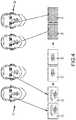
- FIG. 4shows an example of the stereoscopic pair of images 31 at various stages of the method.
- step S 1the stereoscopic pair of images 31 are analyzed to detect the location of the head and in particular the eyes of the source observer 14 within the stereoscopic pair of images 31 . This is performed by detecting presence of a head, tracking the head, and localizing the eyes of the head. Step S 1 may be performed using a variety of techniques that are known in the art.
- Haar feature cascadesfor example as disclosed in Viola and Jones, “Rapid Object Detection using a Boosted Cascade of Simple Features”, CVPR 2001, pp 1-9, which is herein incorporated by reference in its entirety.
- One possible technique for tracking the headis to use the approach of Active Appearance Models to provide the position of the head of the subject, as well as the location of the eyes, for example as disclosed in Cootes et al., “Active shape models—their training and application”, Computer Vision and Image Understanding, 61(1):38-59, January 1995 and in Cootes et al. “Active appearance models”, IEEE Trans. Pattern Analysis and Machine Intelligence, 23(6):681-685, 2001, both of which are herein incorporated by reference in their entireties.
- step S 1typically, a set of individual points (“landmarks”) are set to regions of the face, typically the eyes, for example corners of the eye, upper and lower lid locations, etc., thereby localizing the eyes.
- markstypically, a set of individual points (“landmarks”) are set to regions of the face, typically the eyes, for example corners of the eye, upper and lower lid locations, etc., thereby localizing the eyes.
- step S 2patches representing portions of a digital representation of the head region, which in this example may be referred to image patches, containing the left and right eyes of the head, respectively, are identified in each image 31 of the stereoscopic pair.
- FIG. 4shows the identified image patches 32 of the right eye in each image 31 (the image patches for the left eye being omitted in FIG. 4 for clarity).
- Step S 2may be performed as shown in FIG. 5 , as follows.
- step S 2 - 1image patches 32 containing the left and right eyes of the head are identified in each image 31 of the stereoscopic pair. This is done by identifying an image patch 39 in each image 31 located around the identified points (“landmarks”) corresponding to features of an eye, as shown for example in FIG. 4 .
- step S 2 - 2the image patches 32 identified in step S 2 - 1 are transformed into a normalized coordinate system, being the same normalized coordinate system as used in the machine learning process which is described further below.
- the transformationis chosen to align the points (“landmarks”) of the eye within the image patch that were identified in step S 1 , with predetermined locations in the normalized coordinate system.
- the transformationmay include translation, rotation and scaling, to appropriate extents to achieve that alignment.
- the output of step S 2 - 2is identified image patches 33 of the right eye in each image in the normalized coordinate system as shown for example in FIG. 4 .
- the following stepsmay be performed separately (a) in respect of the image patches containing the left eyes of the head in each image 31 of the stereoscopic pair, and (b) in respect of the image patches containing the right eyes of the head in each image 31 of the stereoscopic pair (in this example).
- the following descriptionwill refer merely to image patches and eyes without specifying the left or right eye, but noting the same steps are performed for both left and right eyes.
- a feature vector 34is derived from plural local descriptors (representing information about a local region in a patch), which in this example may be referred to as local image descriptors, of an image patch 33 in at least one image 31 of the stereoscopic pair (in this example).
- thismay be an image patch in a single image 31 of the stereoscopic pair or may be both images 31 of the stereoscopic pair.
- the local image descriptorsare local image descriptors derived in the normalized coordinate system.
- the feature vectors 34are representations of the image patches 33 that are suitable for use in looking up reference data 35 to be used for adjusting the image patches.
- the reference data 35may comprise reference displacement vector fields that represent transformations of the image patch, or other representations of transformations of the image patch, including compressed representations as described below, and are associated with possible values of the feature vector.
- the reference data 35is obtained and analyzed in advance using a machine learning technique.
- the machine learning techniquemay derive the form of the feature vectors 34 and associate transformations such as the reference displacement vector fields with the possible values of the feature vector.
- a specific example of a machine learning technique applied in the case where it is desired to correct gaze using digital representations of a head region comprising images of the head region,will now be described before reverting to the method of FIG. 3 .
- the training input to the machine learning techniqueis two sets of images (or image patches), which may be stereoscopic pairs of images or monoscopic images, as discussed further below.
- Each setmay comprise images of the head of the same group of individuals but captured from cameras in different locations relative to the gaze so that the perceived gaze differs as between them (in the case where gaze is to be corrected).
- the first setare input images, being images of each individual with an incorrect gaze where the error is known a priori.
- the images in the first setmay be captured by at least one cameras in a known camera location where the gaze of the individual which is in a different known direction.
- the camera locationmay be the location of a camera 13 and while the gaze of the imaged individual is towards the center of the display 11 .
- the second setare output images, being images of each individual with correct gaze for a predetermined observer location relative to a display location in which the image is to be displayed.
- the observer locationis a normal viewing position perpendicular to the center of the display location, for example as shown by the hard outline of the destination observer 24 in the case of the destination device 20 of FIG. 2 .
- the imageis analyzed to detect the location of the head and in particular the eyes using the same technique as used in step S 1 described above, and then image patches containing the left and right eyes of the head, respectively, are identified using the same technique as used in step S 2 described above.
- the following stepsmay then be performed separately (a) in respect of the image patches containing the left eyes of the head in each image, and (b) in respect of the image patches containing the right eyes of the head in each image.
- the following descriptionwill refer merely to image patches and eyes without specifying the left or right eye, but noting the same steps are performed for both left and right eyes in this embodiment.
- Each image patchis transformed into the same normalized coordinate system as used in step S 2 described above.
- the transformationis chosen to align points (“landmarks”) of the eye with predetermined locations in the normalized coordinate system.
- the transformationmay include, for example, translation, rotation and/or scaling, to appropriate extents to achieve that alignment.
- the image patches input and output images of each individualare aligned in the normalized coordinate system.
- the systemFor image data from more than one camera, the system delivers a displacement vector field for the input image from each camera.
- min!
- the displacement vector field Fmay be derived as disclosed in Kononenko et al., “Learning To Look Up: Realtime Monocular Gaze Correction Using Machine Learning”, Computer Vision and Pattern Recognition, 2015, pp. 4667-4675, which is herein incorporated by reference in its entirety, wherein the displacement vector field F is referred to as a “flow field”.
- filter field L⁇ k(P,x,y) ⁇ , which defines a filter kernel for a given location (x,y).
- itcould be the output of a convolution of the patch with a Gaussian filter with width depending on the position x in the image, or a brightness increase of a local pixel depending on the vertical position y.
- editing instructionse.g. image editing instructions
- image editing instructionswhich can be used additionally or as an alternative to the displacement vector field in any of the arrangements disclosed herein, is given by a set of typical image components that make up the edited image area, e.g. texture showing beard stubbles. These are then blended with a factor depending on the image coordinates and local image content (i.e. a texture blending field).
- Other transformation fieldscan be used, such as a brightness adjustment field.
- a machine learning techniqueis used to obtain a map from the displacement vector field F (or other editing instructions such as image editing instructions) of each individual to respective feature vectors derived from plural local (e.g. image) descriptors of a target patch of an input image.
- the local descriptorscapture relevant information of a local part of a patch (e.g. image patch) of an input digital representation of the head region (e.g. an input image) and the set of local descriptors usually form a continuous vectorial output.
- the local descriptors input into the machine learning processare of types expected to provide discrimination between different individuals, although the specific image descriptors are selected and optimized by the machine learning process itself.
- the local descriptorsmay be of any suitable type, some non-limitative examples which may be applied in any combination being as follows.
- the local descriptorsmay include values of individual pixels or a linear combination thereof.
- a linear combinationmay be, for example, a difference between the pixels at two points, a kernel derived within a mask at an arbitrary location, or a difference between two kernels at different locations.
- the local descriptorsmay include distances of a pixel location from the position of an eye point (“landmark”).
- the local descriptorsmay include SIFT features (Scale-invariant feature transform features), for example as disclosed in Lowe, “Distinctive Image Features from Scale-Invariant Keypoints”, International Journal of Computer Vision 60 (2), pp 91-110, which is herein incorporated by reference in its entirety.
- SIFT featuresScale-invariant feature transform features
- the local descriptorsmay include HOG features (Histogram of Oriented Gradients features), for example as disclosed in Dalal et al. “Histograms of Oriented Gradients for Human Detection”, Computer Vision and Pattern Recognition, 2005, pp. 886-893, which is herein incorporated by reference in its entirety.
- HOG featuresHistogram of Oriented Gradients features
- the local descriptorsmay include “low level representations” from pre-classification stages in deep learning neural networks, for example as disclosed in Yang and Ramanan, “Multi-scale recognition with DAG-CNNs”, ICCV 2015, which is herein incorporated by reference in its entirety.
- low level representationsfrom pre-classification stages in deep learning neural networks, for example as disclosed in Yang and Ramanan, “Multi-scale recognition with DAG-CNNs”, ICCV 2015, which is herein incorporated by reference in its entirety.
- an input digital representatione.g. image
- the derivation of the feature vector from plural local descriptorsdepends on the type of machine learning applied.
- the feature vectormay comprise features that are values derived from the local descriptors (e.g. local image descriptors) in a discrete space, being binary values or values discretized into more than two possible values.
- the machine learning techniqueassociates a reference displacement vector field F derived from the training input with each possible value of the feature vector in the discrete space, so the reference data 35 may provide similar functionality to a look-up table, with the machine learning generating a machine learning parameter set that can be used to generate corresponding editing instructions. This allows a reference displacement vector field F to be simply selected from the reference data 35 on the basis of the feature vector 34 derived in step S 3 , as described below.
- the feature vectorcomprises features that are binary values derived from the local descriptors
- the feature vectorhas a binary representation.
- Such binary valuesmay be derived in various ways from the values of descriptors, for example by comparing the value of a descriptor with a threshold, comparing the value of two descriptors, or by comparing the distance of a pixel location from the position of an eye point (“landmark”).
- the feature vectormay comprise features that are discretized values of the local descriptors. In this case, more than two discrete values of each feature are possible.
- Any suitable machine learning techniquemay be applied, for example using a decision tree, a decision forest, a decision fern or an ensemble or combination thereof, or a neural network.
- a suitable machine learning technique using a feature vector comprising features that are binary values derived by comparing a set of individual pixels or a linear combination thereof against a thresholdis disclosed in Ozuysal et al. “Fast Keypoint Recognition in Ten Lines of Code”, Computer Vision and Pattern Recognition, 2007, pp. 1-8, which is herein incorporated by reference in its entirety.
- a suitable machine learning technique using a distance of a pixel location with the position of an eye landmarkis disclosed in Kononenko et al., “Learning To Look Up: Realtime Monocular Gaze Correction Using Machine Learning”, Computer Vision and Pattern Recognition, 2015, pp. 4667-4675, which is herein incorporated by reference in its entirety.
- the feature vectormay comprise features that are discrete values of the local descriptors (e.g. local image descriptors) in a continuous space.
- the machine learning techniqueassociates a reference displacement vector field F (in this example, but other editing instructions could be used) derived from the training input with possible discrete values of the feature vector in the continuous space. This allows a displacement vector field F to be derived from the reference data 35 by interpolation from the reference displacement vector fields based on the relationship between the feature vector 34 derived in step S 3 and the values of the feature vector associated with the reference displacement vector fields.
- Any suitable machine learning techniquemay be applied, for example using support vector regression.
- a suitable machine learning technique using support vector regressionis disclosed in Drucker et al. “Support Vector Regression Machines”, Advances in Neural Information Processing Systems 9, NIPS 1996, 155-161, which is herein incorporated by reference in its entirety.
- the output of the techniqueis a continuously varying set of interpolation directions that form part of the reference data 35 and are used in the interpolation.
- the machine learning techniqueregardless of its type, inherently also derives the form of the feature vectors 34 that is used to derive the reference displacement vector fields F (or other image editing instructions). This is the form of the feature vectors 34 that is derived in step S 3 .
- step S 4at least one displacement vector field 37 representing a transformation of an image patch is derived by using the feature vector 34 derived in step S 3 to look up the reference data 35 . Due to the derivation of the displacement vector field 37 from the reference data 35 , the transformation represented thereby corrects the gaze that will be perceived when the stereoscopic pair of images 31 are displayed.
- the displacement vector field for the image patchis derived by selecting the reference displacement field associated with the actual value of the derived feature vector 34 .
- the displacement vector field for the image patchis derived by interpolating a displacement vector field from the reference displacement vector fields based on the relationship between the actual value of the derived feature vector 34 and the values of the feature vectors associated with the reference displacement vector fields. In the case that the machine learning technique was support vector regression, this may be done using the interpolation directions that form part of the reference data 35 .
- each image 31 of the stereoscopic pairis adjusted by transforming the image patches containing the left and right eyes of the head in accordance with the derived displacement vector fields 37 .
- the adjustmentmay be performed using two alternative methods, as follows.
- a first method for performing step S 5is shown in FIG. 6 and performed as follows.
- step S 5 - 1the image patch is transformed in the normalised coordinate system in accordance with the corresponding displacement vector field 37 in respect of the same image, thereby correcting the gaze.
- step S 5 - 2the transformed image patch output from step S 5 - 1 is transformed out of the normalised coordinate system, back into the original coordinate system of the corresponding image 31 . This is done using the inverse transformation from that applied in step S 2 - 2 .
- step S 5 - 3the transformed image patch output from step S 5 - 2 is superimposed on the corresponding image 31 .
- Thismay be done with a full replacement within an eye region corresponding to the eye itself, and a smoothed transition between the transformed image patch and the original image 31 over a boundary region around the eye region.
- the width of the boundary regionmay be of fixed size or a percentage of the size of the image patch in the original image 31 .
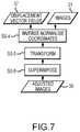
- a second method for performing step S 5is shown in FIG. 7 and performed as follows.
- step S 5 - 4the displacement vector field F is transformed out of the normalised coordinate system, back into the original coordinate system of the corresponding image 31 . This is done using the inverse transformation from that applied in step S 2 - 2 .
- step S 5 - 5the image patch 32 in the coordinate system of the image 31 is transformed in accordance with the displacement vector field F that has been transformed into the same coordinate system in step S 5 - 4 .
- Step S 5 - 6is the same as S 5 - 3 .
- the transformed image patch output from step S 5 - 5is superimposed on the corresponding image 31 . This may be done with a full replacement within an eye region corresponding to the eye itself, and a smoothed transition between the transformed image patch and the original image 31 over a boundary region around the eye region.
- the width of the boundary regionmay be of fixed size or a percentage of the size of the image patch in the original image 31 .
- FIG. 8depicts a method of generating reference data (including reference data 37 of the type described in the specific examples discussed above) for adjusting a digital representation of a head region.
- the digital representation of the head regioncomprises or consists of an image of the head region.
- the digital representation of the head regioncomprises or consists of a three-dimensional digital representation (representing, for example, three-dimensional geometrical information).
- the three-dimensional digital representationmay be obtained from depth measurements, using for example a time-of-flight camera.
- the digital representation of the head regionis usable to provide a computer generated display of the head region.
- the adjustment of the digital representationcomprises converting a two-dimensional digital representation of the head region to a three-dimensional digital representation of the head region.
- the digital representation of the head region(prior to adjustment, after adjustment, or both) comprises a three-dimensional digital representation
- the three-dimensional digital representationmay comprise a point cloud, a particle system, or a mesh representation.
- the mesh representationmay comprise one or more of: a polygonal surface, a multi-resolution surface, a subdivision surface.
- the digital representationmay comprise a three-dimensional digital representation and texture information associated with the three-dimensional digital representation, e.g. via a texture map.
- the digital representationmay comprise a three-dimensional geometrical representation and color information (e.g. obtained from an optical camera) aligned with the three-dimensional geometrical representation.
- Other volumetric representationssuch as particle system or implicit definitions such as signed distance functions may also be used.
- the methodcomprises a step S 100 of receiving training data 100 .
- the training data 100may be provided for example via a communications interface 112 (e.g. connecting to an external data connection or storage device) connected to a data processing unit 120 that is to perform the method (as depicted schematically in FIG. 10 ).
- the training data 100comprises a set of input patches.
- a patchconsists of a target portion of a digital representation of a head region.
- the patchmay be referred to as an image patch.
- Each input patch(e.g. input image patch) comprises a target feature of the digital representation (e.g. image) of the head region prior to adjustment of the digital representation (e.g. adjustment of the image to be displayed) of the head region.
- the target featureis the same for each input patch.
- the target featuremay comprise one or more of the following: an eye region comprising at least part of an eye (as in the specific examples discussed above with reference to FIG. 4 for example), a nose region comprising at least part of a nose, a mouth region comprising at least part of a mouth, a chin region comprising at least part of a chin, and a neck region comprising at least part of a neck.
- each input image patchcomprises a portion of the image of the head region corresponding to the target feature, such as the above-mentioned eye region, nose region, mouth region, chin region, or neck region.
- the target featurecomprises an eye region comprising at least part of an eye and the adjustment of the digital representation (e.g. image) of the head region comprises adjusting a gaze direction.
- the target featurecomprises a nose region comprising at least part of a nose and the adjustment of the digital representation (e.g. image) of the head region comprises adjusting a shape and/or texture of the nose (e.g. to make nose look smaller and/or slimmer by a fixed proportion, similar to the effect of a “tele lens”).
- the adjustment of the digital representation (e.g. image) of the head regioncomprises adjusting a shape and/or texture of the nose (e.g. to make nose look smaller and/or slimmer by a fixed proportion, similar to the effect of a “tele lens”).
- the target featurecomprises a chin region comprising at least part of a chin and the adjustment of the digital representation (e.g. image) of the head region comprises adjusting a shape and/or texture of the chin (e.g. to reduce or remove double chin appearance).
- the adjustment of the digital representation (e.g. image) of the head regioncomprises adjusting a shape and/or texture of the chin (e.g. to reduce or remove double chin appearance).
- the target featurecomprises a neck region comprising at least part of a neck and the adjustment of the digital representation (e.g. image) of the head region comprises adjusting a shape and/or texture of the neck (e.g. to reduce or remove wrinkles).
- the adjustment of the digital representation (e.g. image) of the head regioncomprises adjusting a shape and/or texture of the neck (e.g. to reduce or remove wrinkles).
- the target featurecomprises a hair region comprising hair and the adjustment of the digital representation (e.g. image) of the head region comprises adjusting a color of the hair (e.g. by a fixed hue).
- the input patchesmay be obtained using the methodology described above with reference to steps S 2 - 1 and S 2 - 2 , except that stereoscopic pairs of images are not necessarily required.
- the input patchesmay be obtained by using identified points (“landmarks”) corresponding to features of an eye to locate the relevant region of the digital representation (e.g. image) of the head region (e.g. surrounding the eye) and/or transformation of the input patch into a normalized coordinate system, including alignment of the landmarks with predetermined locations in the normalized coordinate system using translation, rotation and/or scaling.
- the training data 100further comprises a set of output patches.
- each patchconsists of a target portion of a digital representation of a head region.
- the patchmay be referred to as an image patch.
- the output patchese.g. output images patches
- Each output patchcomprises the target feature of the digital representation (e.g. image) of the head region after adjustment of the digital representation (e.g. adjustment of the image to be displayed) of the head region.
- each output patchcomprises an eye region that has been adjusted so that the gaze appears to be in the desired direction (e.g. directly towards a destination observer 24 ).
- the methodfurther comprises a step S 101 comprising using a first machine learning algorithm to generate first reference data 101 using the training data 100 .
- the first reference data 101comprises editing instructions (e.g. image editing instructions) for adjusting the digital representation (e.g. image) of the head region for a range of possible digital representations (e.g. digital representations representing different states of the head, such as different positions and/or orientations, optionally represented as different images) of the head region.
- the methodfurther comprises a step S 102 comprising using a second machine learning algorithm to generate second reference data 102 .
- the second machine learning algorithmuses the same training data 100 as the first machine learning algorithm in step S 101 .
- the second machine learning algorithmfurther uses the first reference data 101 output by the first machine learning algorithm in step S 101 .
- the second reference data 102comprises editing instructions (e.g. image editing instructions) for adjusting the digital representation (e.g. image) of the head region for a range of possible digital representations (e.g. different positions and/or orientations, optionally represented as different images) of the head region.
- the first reference data 101comprises first editing instructions (e.g. first image editing instructions) for a range of possible configurations of the target feature (e.g. different gaze directions and/or eye morphologies in the case where the target feature comprises an eye region) and first selection instructions for selecting editing instructions (from the first editing instructions) for a particular input patch (e.g. input image patch) based on the configuration of the target feature of the input patch (e.g. the particular gaze direction and/or particular eye morphology of that input patch).
- first editing instructionse.g. first image editing instructions
- a range of possible configurations of the target featuree.g. different gaze directions and/or eye morphologies in the case where the target feature comprises an eye region
- first selection instructionsfor selecting editing instructions (from the first editing instructions) for a particular input patch (e.g. input image patch) based on the configuration of the target feature of the input patch (e.g. the particular gaze direction and/or particular eye morphology of that input patch).
- the second reference datacomprises second editing instructions (e.g. second image editing instructions) for a range of possible configurations of the target feature and second selection instructions for selecting editing instructions (from the second editing instructions) for a particular input patch (e.g. input image patch) based on the configuration of the target feature of the input patch.
- second editing instructionse.g. second image editing instructions
- second selection instructionsfor selecting editing instructions (from the second editing instructions) for a particular input patch (e.g. input image patch) based on the configuration of the target feature of the input patch.
- the configuration of the target feature of each input patchmay be represented by a feature vector derived from plural local descriptors (e.g. local image descriptors) of the input patch, as described above with reference to step S 3 of FIG. 3 for the particular case where stereoscopic pairs of images containing eye regions are processed (but the method is applicable more generally than this particular case).
- the feature vectormay take various forms but is generally adapted to be suitable for looking up editing instructions for performing adjustment of the digital representation (e.g. image) of the head region.
- the first and second selection instructionsdefine how the feature vector is used to select editing instructions for the input patch.
- the editing instructionscomprise a displacement vector field defining how the input patch is to be transformed to perform the adjustment.
- the displacement vector fieldmay take any of the forms discussed above.
- the editing instructionsare not limited to displacement vector fields, however.
- Other editing operationsmay additionally or alternatively be associated with the features vectors to perform other desired adjustments of the digital representation (e.g. image) of the head region, including for example adjustments to pixel colors or intensities, or changes to underlying geometries (e.g. via a filter field, brightness adjustment field, or texture blending field).
- a first editing algorithm(e.g. first image editing algorithm) is used by the first machine learning algorithm to define how the first editing instructions are to be applied to an input patch to derive an output patch.
- a second editing algorithm(e.g. second image editing algorithm) is used by the second machine learning algorithm to define how the second editing instructions are to be applied to an input patch to derive an output patch.
- the first and second editing algorithmsmay comprise any of the methods described above for implemented step S 5 of FIG. 3 , described with reference to FIGS. 6 and 7 .
- the second editing instructions in the second reference dataare provided in a compressed representation.
- the compressed representationmay comprise a principle component analysis representation or a wavelet representation for example.
- the first and second editing algorithmsmay be adapted to define how to operate efficiently in this context.
- the second editing instructionsare principle component analysis components of a principle component analysis of the first editing instructions.
- the second editing algorithmin this case transforms the second editing instructions into the first editing instructions by inverse principle component analysis transform.
- the second editing instructionsare wavelet components of the first editing instructions.
- the second editing algorithmin this case transforms the second editing instructions into the first editing instructions by inverse wavelet transform.
- the first selection instructions for the first reference dataare able to select between a larger number of alternative editing instructions (e.g. image editing instructions) than the second selection instructions for the second reference data.
- the first machine learning algorithmmay thus be described as having more input parameters than the second machine learning algorithm.
- the first machine learning algorithmmay provide higher accuracy than the second machine learning algorithm but will typically operate considerably slower.
- the first selection instructionsmay be significantly more complex (e.g. involving linear algebra or other relatively computer intensive operations) than the second selection instructions (where the selection instructions may resemble a computationally straightforward look-up table, a combination of a look-up table and a tree structure, or similar).
- the first machine learning algorithmcomprises a neural network (known to provide relatively high accuracy, but at the expense of relatively high computational demands).
- the second machine learning algorithmmay comprises a regression forest (known to provide higher computational efficiency, but at the expense of reduced accuracy).
- the inventorshave found that the combination of the two different machine learning algorithms provides reference data that can be used in an adjustment method with high efficiency while still achieving high adjustment accuracy.
- the first machine learning algorithmmay alternatively comprise a support vector machine or a generative adversarial network (GAN).
- GANgenerative adversarial network
- the second machine learning algorithmmay alternatively comprise regression ferns, cluster centres, a lookup table, or separable filter banks.
- the first machine learning algorithmcomprises a first neural network and the second machine learning algorithm comprises a second neural network, wherein the second neural network comprises fewer layers and/or smaller convolution fields than the first neural network.
- FIG. 9schematically depicts data flow in a detailed example of the method of generating reference data of FIG. 8 .
- the first and second machine learning algorithmsare respectively labelled MLA 1 and MLA 2 .
- the first machine learning algorithm MLA 1receives the training data (labelled TD) and, optionally, the first editing algorithm EA 1 , and a similarity metric SM.
- the similarity metric SMprovides a numerical value to measure similarity between an adjusted image and a desired image and can be used to control the first machine learning algorithm MLA 1 and the second machine learning algorithm MLA 2 to vary the extent to which differences are penalized according to the nature of the differences.
- the similarity metric SMmay be configured to penalize reductions in portions of images that it is desired to maintain (e.g.
- the training datamay comprise an average absolute or square difference between the adjusted image and a target, or average absolute or square difference between low level representations of the adjusted image and target, such as low level features from a deep learning network (as discussed above).
- the first editing algorithm EA 1receives auxiliary data AuxD, which defines a basis set used for providing a compressed representation of image editing instructions.
- the first machine learning algorithm MLA 1outputs first selection instructions LA 1 and first editing instructions ED 1 .
- the second machine learning algorithm MLA 2receives the same training data TD and, optionally, the second editing algorithm EA 2 , and the similarity metric SM.
- the second machine learning algorithm MLA 2additionally receives the first editing instructions ED 1 .
- the second machine learning algorithmoutputs second selection instructions LA 2 and second editing instructions ED 2 .
- the second machine learning algorithm MLA 2thus gets the editing instructions to match or to approximate, and does not have to infer these from the matched input images as MLA 1 .
- FIG. 10depicts a device 110 for generating the reference data.
- the device 110comprises a data processing unit 120 configured to perform the method of generating the reference data according to any of the disclosed embodiments.
- the data processing unit 110may be implemented by a processor executing a suitable computer program or by dedicated hardware or by some combination of software and hardware. Data input/output may be provided via a communications interface 112 .
- the computer programmay comprise instructions in any suitable language and may be stored on a computer readable storage medium, which may be of any type, for example: a recording medium which is insertable into a drive of the computing system and which may store information magnetically, optically or opto-magnetically; a fixed recording medium of the computer system such as a hard drive; or a computer memory.
- FIG. 11depicts a method of adjusting a digital representation of a head region.
- the digital representationcomprises an image of a head region, but the method can be adapted to use any of the digital representations discussed above (e.g. to additionally or alternatively process three-dimensional digital representations).
- the methodmay use reference data generated using any of the methods of generating reference data disclosed herein or may use reference data generated using other methods.
- the methodcomprises a step S 200 in which a target patch (in this case an image patch) is identified in an image 200 of a head region that is to be adjusted.
- the target patchcomprises a target feature of the head region.
- the target featuremay take any of the forms discussed above.
- the step S 200may optionally comprise detecting a head and/or eye location as described above with reference to step S 1 of FIG. 3 .
- the step S 200may optionally further comprise identifying image patches using the methodology described above with reference to steps S 2 - 1 and S 2 - 2 of FIG. 5 , except that the image patches do not necessarily need to be identified as stereoscopic pairs (although they may be if desired).
- a feature vectoris derived from plural local descriptors (e.g. local image descriptors) of the target (e.g. image) patch.
- the feature vectormay be derived using the methodology described above with reference to step S 3 of FIG. 3 .
- the feature vectormay take any of the forms discussed above.
- the feature vectoris used to select editing instructions (e.g. image editing instructions) from reference data 102 .
- the reference data 102comprising editing instructions for a range of possible values of the feature vector (representing for example different gaze directions and/or eye morphologies in the case where the target feature comprises an eye region).
- step S 203the selected editing instructions are applied to the target patch to adjust the image of the head region (e.g. to correct a gaze direction).
- the editing instructionsare provided in a compressed representation, comprising for example one or more of the following: a principle component analysis representation; a wavelet representation; Fourier and/or discrete cosine transform components; cluster centers.
- a compressed representationreduces data storage and bandwidth requirements during use of the image editing instructions to perform adjustment of the digital representation (e.g. image) of the head region.
- the reference data containing the editing instructionsmay be generated using any of the embodiments disclosed herein.
- the reference datamay comprise the second reference data discussed above for example.
- Reference to editing instructions hereinis understood to encompass any data which can be used to define how a digital representation (e.g. image) of a head region should be adjusted to achieve a desired aim (e.g. gaze correction or conversion from a two-dimensional digital representation to a three-dimensional digital representation or both).
- the editing instructionsmay comprise data that can used directly to modify a digital representation (e.g. image), such as a vector field, or intermediate data such as a machine learning parameter set that can be used to generate data that can be used directly to modify the digital representation (e.g. image).
- FIG. 12schematically depicts data flow in a detailed example of a method of adjusting a digital representation of a head region in the case where the digital representation comprises an image, using reference data generated according to the detailed example of FIG. 9 .
- Input data IDis provided from a sensor system SS (e.g. comprising one or more cameras).
- the input data IDis input to the second selection instructions LA 2 to select editing instructions appropriate to the input data ID from the second editing instructions ED 2 .
- the selected editing instructionswhich in this example are provided in a compressed representation (e.g.
- the output data ODcomprises an adjusted image of the head region and is displayed via a display DS.
- the method of adjusting a digital representation of a head regionmay be implemented in an image processor 30 provided in various different devices.
- an image processor 30provided in various different devices.
- the source device 10 and the destination device 10communicate over such a telecommunications network 50 .
- the source device 10includes a telecommunications interface 17 and the destination device 20 includes a telecommunications interface 27 .
- the image processor 30is provided in the source device 10 and is provided with an image of a head region directly from a camera system 12 (in this example, a stereoscopic pair of images).
- the telecommunications interface 17is arranged to transmit the adjusted images 38 over the telecommunications network 50 to the destination device 20 for display thereon.
- the destination device 20includes an image display module 28 that controls the display 26 .
- the adjusted images 38are received in the destination device 20 by the telecommunications interface 27 and supplied to the image display module 28 which causes them to be displayed on the display 26 .
- the destination device 20includes a camera system 23 and an observer location module 29 .
- the camera system 23captures an image of the destination observer 24 .
- the observer location module 29derives the location data 40 .
- the observer location module 29includes a head tracking module that uses the output of the camera system 23 to detect the location of the destination observer 24 . Where the relative observer location also takes into account the location of the image displayed on the display 21 , the observer location module 29 obtains the location of the image displayed on the display 21 from the image display module 28 .
- the telecommunications interface 17is arranged to transmit the location data 40 over the telecommunications network 50 to the source device 10 for use thereby.
- the above descriptionrefers to a method applied to images supplied from a source device 10 to a destination device 20
- the methodmay equally be applied to images supplied in the opposite direction from the destination device 20 to the source device 10 , in which case the destination device 20 effectively becomes the “source device” and the source device 10 effectively becomes the “destination device”.
- the labels “source” and “destination”may be applied to both devices, depending on the direction of communication being considered.
- FIG. 14depicts a further embodiment of a method of generating reference data for adjusting a digital representation of a head region using a framework of the type depicted in FIG. 8 .
- the training data 100 received in step S 100comprises a set of input digital representations of a head region (e.g. input patches each consisting of a target portion of a two-dimensional digital representation of the head region, such as a captured image).
- a first machine learning algorithm MLA 1is trained using the training data 100 , the training causing the first machine learning algorithm MLA 1 to become capable of performing an adjustment of a digital representation of a head region.
- the adjustment of the digital representationcomprises converting from a two-dimensional digital representation to a three-dimensional digital representation (e.g. converting from a 2D image of a portion of a head region to a 3D mesh of a portion of the head region).
- the trained first machine learning algorithm MLA 1is then used to generate first reference data 101 .
- the first reference data 101comprises an adjusted digital representation of the head region for each of at least a subset of the input digital representations in the training data 100 .
- Each adjusted digital representationis obtained by performing the adjustment that the first machine learning algorithm MLA 1 was trained to perform.
- a second machine learning algorithm MLA 2is trained using at least a subset of the training data 100 used to train the first machine learning algorithm MLA 2 and the first reference data 101 .
- the trainingcauses the second machine learning algorithm MLA 2 to become capable of performing the same adjustment of a digital representation of a head region as the first machine learning algorithm MLA 1 .
- the first machine learning algorithm MLA 1comprises a first encoder 306 A and a first predictor 308 A.
- the training data 100is input to the first encoder 306 A.
- the first encoder 306 Acomprises a feature extractor algorithm.
- the feature extractor algorithmderives informative and non-redundant values from the training data 100 (i.e. extracts meaningful features from the training data 100 ).
- Examples of feature extractor algorithmsinclude Convolutional Neural Networks, Principal Component Analysis, SIFT (Scale Invariant Feature Transform).
- An output from the first encoder 306 Ais input to a first predictor 308 A.
- the first predictor 308 Agenerates an adjusted version of each input digital representation in the training data 100 based on the output of the first encoder 306 A (e.g. features extracted by the first encoder 306 A).
- each input digital representationcomprises a two-dimensional digital representation (e.g. a two-dimensional image) and the adjusted version of each input digital representation comprises a three-dimensional digital representation (e.g. a mesh).
- Each three-dimensional digital representationis input to a renderer 310 .
- the renderer 310synthesizes one or more two-dimensional digital representations corresponding to each input three-dimensional digital representation (e.g. one or more photorealistic images of the head region defined by the three-dimensional digital representation).
- the output from the renderer 310is then input to a second encoder 306 B.
- the second encoder 306 Bmay be identical to the first encoder 306 A.
- An output from the second encoder 306 Bis input to a second predictor 308 B.
- the second predictor 308 Bmay be identical to the first predictor 308 A.
- a first regularizer 314is provided that compares the output from the first encoder 306 A with the output from the second encoder 306 B and imposes one or more predetermined first constraints.
- a second regularizer 316is provided that compares the output from the first predictor 308 A with the output from the second predictor 308 B and imposes one or more predetermined second constraints.
- the first regularizer 314 and the second regularizer 316may use a set of semantically meaningful constraints (examples of the first constraints and second constraints) or additional information to help reach a desirable solution and to prevent overfitting.
- the constraintsmay help to ensure that generated three-dimensional digital representations are natural looking for example, by requiring high levels of natural levels of smoothness.
- the first machine learning algorithm MLAiteratively updates properties of the first predictor 308 A and the second predictor 308 B (e.g.
- the first encoder 306 A and second encoder 306 Bmay also be iteratively updated.
- the training of the first machine learning algorithm MLA 1thus comprises iteratively using a rendering process to generate a two-dimensional digital representation from a three-dimensional digital representation generated by the first machine learning algorithm MLA 1 and comparing the generated digital representation with a corresponding digital representation in the training data.
- the first machine learning algorithm MLA 1is considered trained and the resulting output from the second predictor 308 B can be used to provide the first reference data 101 (which in this embodiment comprises three-dimensional digital representations corresponding to the input two-dimensional representations in the training data 100 ).
- new two-dimensional and/or three-dimensional digital representationscan be generated by applying editing instructions either to two-dimensional digital representations (which are converted to three-dimensional digital representations by the trained first machine learning algorithm MLA 1 ) or to three-dimensional digital representations output by the trained first machine learning algorithm MLA 1 ).
- the first reference data 101may include the two-dimensional digital representations and/or three-dimensional representations after modification by the editing instructions.
- a set of thus generated three-dimensional digital representations output as first reference data 101 and corresponding two-dimensional digital representationsare used to train the second machine learning algorithm MLA 2 (input at block 304 ).
- the second machine learning algorithm MLA 2also comprises an encoder 306 C and a predictor 308 C, which may be configured as described above for the first machine learning algorithm MLA 1 .
- the predictor 308 C(and, optionally, the encoder 308 C) may be iteratively updated (trained) using a regularizer 318 based on the input training data 100 and first reference data 101 .
- the second machine learning algorithm MLA 2learns to convert between a two-dimensional digital representation and a three-dimensional digital representation based on the mapping between two-dimensional digital representations and three-dimensional digital representations derived using the renderer 310 in the first machine learning algorithm MLA 1 .
- the mapping derived by the first machine learning algorithm MLA 1is reliable, the second machine learning algorithm MLA 2 will be able to provide accurate conversion between two-dimensional digital representations and three-dimensional digital representations using a simpler trained machine learning model (which can be stored and operated using fewer computing resources than the first machine learning algorithm MLA 1 ).
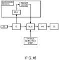
- FIG. 15depicts data flow in an example implementation of an embodiment in which a pre-trained second machine learning algorithm MLA 2 is updated (i.e. trained further) in at or near input data frame rate (i.e. online).
- a plurality of the digital representations (e.g. images) of the head regionmay be received as input data ID (e.g. from a sensor system SS as described above) and adjusted (e.g. as described above with reference to FIGS. 11, 12 and 14 ) to provide output data OD that is subsequently displayed via display DS (as described above with reference to FIG. 12 ).
- the input data IDmay comprise a set of input patches, each input patch comprising a target feature of a digital representation of a head region prior to adjustment of the digital representation of the head region, wherein the target feature is the same for each input patch.
- the adjustmentmay be performed using a pre-trained version of the second machine learning algorithm MLA 2 , optionally in combination with a geometrical model.
- the input data IDmay comprise digital representations captured at different points in times, such as different frames in a sequence of images obtained by the sensor system SS in a video capture mode.
- the methodcomprises updating the pre-trained second machine learning algorithm MLA 2 using first reference data (e.g. editing instructions) generated by the first machine learning algorithm MLA 1 using one or more of the received digital representations (from the input data ID).
- the first reference datamay comprise a set of editing instructions in one-to-one correspondence with the input patches, each editing instruction being for adjusting the digital representation of the head region.
- the first reference data for the updatingis generated in a background process and the second machine learning algorithm MLA 2 is updated at or near input data frame rate (i.e. online).
- the updatingthus uses a pre-trained version of the first machine learning algorithm MLA 1 (which, as described above, is configured to provide more highly detailed reference data at the expense of higher computational demands, relative to the second machine learning algorithm MLA 2 ) to generate first reference data that is used to update the second machine learning algorithm MLA 2 .
- the first machine learning algorithm MLA 1is slower than the second machine learning algorithm MLA 2 (which will normally be the case where the first machine learning algorithm MLA 1 is configured to provide more highly detailed reference data than the second machine learning algorithm MLA 2 )
- only a subset of the input data ID(comprising the received and adjusted digital representations) are used to update the second machine learning algorithm MLA 2 , thereby allowing the updating process to keep up with the adjusting of the input data ID by the second machine learning algorithm MLA 2 to provide the output data OD.
- Any of various known techniquesmay be used to perform the updating of the second machine learning algorithm MLA 2 .
- the online updatingmay be performed as described in Amir Saffari, Christian Leistner, Jakob Santner, Martin Godec, and Horst Bischof, “On-line Random Forests,” in 3rd IEEE ICCV Workshop on On-line Computer Vision, 2009, which is herein incorporated by reference in its entirety, or as described in Online Deep Learning: Learning Deep Neural Networks on the Fly, Doyen Sahoo, Quang Pham, Jing Lu, Steven C. H., Hoi School of Information Systems, Singapore Management University (https://arxiv.org/pdf/1711.03705.pdf), which is herein incorporated by reference in its entirety.
- the second machine learning algorithm MLA 2can therefore be gradually improved during use, as more input data ID are encountered and processed by the system.
- receiving training datacomprising:
- the first reference datacomprising image editing instructions for adjusting the image of the head region for a range of possible images of the head region
- the second reference datacomprising image editing instructions for adjusting the image of the head region for a range of possible images of the head region.
- the first reference datacomprise first image editing instructions for a range of possible configurations of the target feature and first selection instructions for selecting image editing instructions for a particular input image patch from the first image editing instructions based on the configuration of the target feature of the input image patch;
- the second reference datacomprise second image editing instructions for a range of possible configurations of the target feature and second selection instructions for selecting image editing instructions for a particular input image patch from the second image editing instructions based on the configuration of the target feature of the input image patch.
- a first image editing algorithmis used by the first machine learning algorithm to define how the first image editing instructions are to be applied to an input image patch to derive an output image patch;
- a second image editing algorithmis used by the second machine learning algorithm to define how the second image editing instructions are to be applied to an input image patch to derive an output image patch.
- the second image editing instructionsare principle component analysis components of a principle component analysis of the first image editing instructions.
- the second image editing algorithmis configured to transform the second image editing instructions into the first image editing instructions by inverse principle component analysis transform.
- the second image editing instructionsare wavelet components of the first image editing instructions
- the second image editing algorithmis configured to transform the second image editing instructions into the first image editing instructions by inverse wavelet transform.
- the target featurecomprises an eye region comprising at least part of an eye and the adjustment of the image of the head region comprises adjusting a gaze direction;
- the target featurecomprises a nose region comprising at least part of a nose and the adjustment of the image of the head region comprises adjusting a shape and/or texture of the nose;
- the target featurecomprises a chin region comprising at least part of a chin and the adjustment of the image of the head region comprises adjusting a shape and/or texture of the chin;
- the target featurecomprises a neck region comprising at least part of a neck and the adjustment of the image of the head region comprises adjusting a shape and/or texture of the neck;
- the target featurecomprises a hair region comprising hair and the adjustment of the image of the head region comprises adjusting a color of the hair.
- the image patchcomprising a target feature of the image of the head region
- the feature vectoruses the feature vector to select image editing instructions from reference data, the reference data comprising image editing instructions for a range of possible values of the feature vector;
- the reference datacomprises the second reference data generated by the method of any of clauses 1-17.
- the image patchcomprising a target feature of the image of the head region
- the feature vectoruses the feature vector to select image editing instructions from reference data, the reference data comprising image editing instructions for a range of possible values of the feature vector;
- the image editing instructions in the reference dataare provided in a compressed representation.
- receive training datacomprising:
- the image patchcomprising information about a target feature of the image of the head region
- the feature vectoruses the feature vector to select image editing instructions from reference data, the reference data comprising image editing instructions for a range of possible values of the feature vector;
- the image editing instructions in the reference dataare provided in a compressed representation.
Landscapes
- Engineering & Computer Science (AREA)
- Physics & Mathematics (AREA)
- Theoretical Computer Science (AREA)
- General Physics & Mathematics (AREA)
- Software Systems (AREA)
- General Engineering & Computer Science (AREA)
- Computing Systems (AREA)
- Mathematical Physics (AREA)
- Data Mining & Analysis (AREA)
- Evolutionary Computation (AREA)
- General Health & Medical Sciences (AREA)
- Molecular Biology (AREA)
- Biophysics (AREA)
- Biomedical Technology (AREA)
- Artificial Intelligence (AREA)
- Computational Linguistics (AREA)
- Life Sciences & Earth Sciences (AREA)
- Health & Medical Sciences (AREA)
- Architecture (AREA)
- Computer Graphics (AREA)
- Computer Hardware Design (AREA)
- Computer Vision & Pattern Recognition (AREA)
- Image Analysis (AREA)
- Feedback Control In General (AREA)
Abstract
Description
F={u(x,y),v(x,y)}
where u and v define the horizontal and vertical components of the vector at each position (x,y).
O(x,y)=I(x+u(x,y),y+v(x,y))
Σ|O(x,y)−I(x+u′(x,y),y+v′(x,y))|=min!
O(x,y)=I(x+u(x,y),y+v(x,y))
O(x,y)=I(x+u(x,y),y+v(x,y))
but this is now performed in the coordinate system of the
- 1. A method of generating reference data for adjusting an image of a head region, the method comprising:
- a set of input image patches, each input image patch comprising a target feature of an image of a head region prior to adjustment of the image of the head region, wherein the target feature is the same for each input image patch; and
- a set of output image patches in one-to-one correspondence with the input image patches, each output image patch comprising the target feature of the image of the head region after adjustment of the image of the head region;
- 2. The method of
clause 1, wherein:
- 3. The method of
clause 2, wherein the configuration of the target feature of each input image patch is represented by a feature vector derived from plural local image descriptors of the input image patch, and the first and second selection instructions define how the feature vector is used to select image editing instructions for the input image patch. - 4. The method of
clause - 5. The method of
clause - 6. The method of any of clauses 2-5, wherein:
- 7. The method of clause 6, wherein:
- 8. The method of clause 6, wherein:
- 9. The method of any of clauses 2-8, wherein the first selection instructions for the first reference data are able to select between a larger number of alternative image editing instructions than the second selection instructions for the second reference data.
- 10. The method of any preceding clause, wherein the first machine learning algorithm is of a different machine learning algorithm type than the second machine learning algorithm.
- 11. The method of any preceding clause, wherein the first machine learning algorithm comprises one or more of the following: a neural network; a support vector machine; a generative adversarial network, GAN.
- 12. The method of any preceding clause, wherein the second machine learning algorithm comprises one or more of the following: a regression forest; regression ferns, cluster centres, a lookup table, separable filter banks.
- 13. The method of any of clauses 1-10, wherein the first machine learning algorithm comprises a first neural network and the second machine learning algorithm comprises a second neural network, wherein the second neural network comprises fewer layers and/or smaller convolution fields than the first neural network.
- 14. The method of any preceding clause, wherein the target feature comprises one or more of the following: an eye region comprising at least part of an eye, a nose region comprising at least part of a nose, a mouth region comprising at least part of a mouth, a chin region comprising at least part of a chin, a neck region comprising at least part of a neck, and a hair region comprising hair.
- 15. The method of any of clauses 1-13, wherein:
- 16. The method of any preceding clause, wherein the second image editing instructions in the second reference data are provided in a compressed representation.
- 17. The method of
clause 16, wherein the compressed representation comprises one or more of the following: a principle component analysis representation; a wavelet representation; Fourier and/or discrete cosine transform components; cluster centres. - 18. A method of adjusting an image of a head region, the method comprising:
- 19. A method of adjusting an image of a head region, the method comprising:
- 20. The method of clause 19, wherein the compressed representation comprises one or more of the following: a principle component analysis representation; a wavelet representation; Fourier and/or discrete cosine transform components; cluster centres.
- 21. A computer program capable of execution by a processor and arranged on execution to cause the processor to perform a method according to any of the preceding clauses.
- 22. A computer readable storage medium storing a computer program according to
clause 21. - 23. A device for generating reference data for adjusting an image of a head region, the device comprising a data processing unit arranged to:
- a set of input image patches, each input image patch comprising information about a target feature of an image of the head region prior to adjustment of the image of the head region, wherein the target feature is the same for each input image patch; and
- a set of output image patches in one-to-one correspondence with the input image patches, each output image patch comprising the target portion of the image of the head region after adjustment of the image of the head region;
- 24. A device for adjusting an image of a head region, the device comprising an image processor arranged to process the image of the head region by:
- 25. The device of
clause 24, further comprising a telecommunications interface arranged to transmit the adjusted image over a telecommunications network to a destination device for display thereon.
Claims (19)
Priority Applications (5)
| Application Number | Priority Date | Filing Date | Title |
|---|---|---|---|
| US16/057,566US10740985B2 (en) | 2017-08-08 | 2018-08-07 | Adjusting a digital representation of a head region |
| US16/937,254US11232647B2 (en) | 2017-08-08 | 2020-07-23 | Adjusting a digital representation of a head region |
| US17/572,964US11836880B2 (en) | 2017-08-08 | 2022-01-11 | Adjusting a digital representation of a head region |
| US18/513,258US12307621B2 (en) | 2017-08-08 | 2023-11-17 | Adjusting a digital representation of a head region |
| US19/211,945US20250278914A1 (en) | 2017-08-08 | 2025-05-19 | Adjusting a digital representation of a head region |
Applications Claiming Priority (3)
| Application Number | Priority Date | Filing Date | Title |
|---|---|---|---|
| US201762542661P | 2017-08-08 | 2017-08-08 | |
| US201762543587P | 2017-08-10 | 2017-08-10 | |
| US16/057,566US10740985B2 (en) | 2017-08-08 | 2018-08-07 | Adjusting a digital representation of a head region |
Related Child Applications (1)
| Application Number | Title | Priority Date | Filing Date |
|---|---|---|---|
| US16/937,254ContinuationUS11232647B2 (en) | 2017-08-08 | 2020-07-23 | Adjusting a digital representation of a head region |
Publications (2)
| Publication Number | Publication Date |
|---|---|
| US20190051057A1 US20190051057A1 (en) | 2019-02-14 |
| US10740985B2true US10740985B2 (en) | 2020-08-11 |
Family
ID=65271511
Family Applications (5)
| Application Number | Title | Priority Date | Filing Date |
|---|---|---|---|
| US16/057,566ActiveUS10740985B2 (en) | 2017-08-08 | 2018-08-07 | Adjusting a digital representation of a head region |
| US16/937,254ActiveUS11232647B2 (en) | 2017-08-08 | 2020-07-23 | Adjusting a digital representation of a head region |
| US17/572,964ActiveUS11836880B2 (en) | 2017-08-08 | 2022-01-11 | Adjusting a digital representation of a head region |
| US18/513,258ActiveUS12307621B2 (en) | 2017-08-08 | 2023-11-17 | Adjusting a digital representation of a head region |
| US19/211,945PendingUS20250278914A1 (en) | 2017-08-08 | 2025-05-19 | Adjusting a digital representation of a head region |
Family Applications After (4)
| Application Number | Title | Priority Date | Filing Date |
|---|---|---|---|
| US16/937,254ActiveUS11232647B2 (en) | 2017-08-08 | 2020-07-23 | Adjusting a digital representation of a head region |
| US17/572,964ActiveUS11836880B2 (en) | 2017-08-08 | 2022-01-11 | Adjusting a digital representation of a head region |
| US18/513,258ActiveUS12307621B2 (en) | 2017-08-08 | 2023-11-17 | Adjusting a digital representation of a head region |
| US19/211,945PendingUS20250278914A1 (en) | 2017-08-08 | 2025-05-19 | Adjusting a digital representation of a head region |
Country Status (5)
| Country | Link |
|---|---|
| US (5) | US10740985B2 (en) |
| EP (2) | EP3665553B1 (en) |
| CN (1) | CN111183405A (en) |
| ES (1) | ES2967691T3 (en) |
| WO (1) | WO2019032604A1 (en) |
Cited By (6)
| Publication number | Priority date | Publication date | Assignee | Title |
|---|---|---|---|---|
| US11113536B2 (en)* | 2019-03-15 | 2021-09-07 | Boe Technology Group Co., Ltd. | Video identification method, video identification device, and storage medium |
| US11347308B2 (en)* | 2019-07-26 | 2022-05-31 | Samsung Electronics Co., Ltd. | Method and apparatus with gaze tracking |
| US20220354193A1 (en)* | 2021-05-07 | 2022-11-10 | Cranial Technologies, Inc. | Pediatric head covering for use with three-dimensional imaging |
| US20230281979A1 (en)* | 2020-08-03 | 2023-09-07 | Xuhui Jia | Systems and Methods for Training Machine-Learned Visual Attention Models |
| US12307621B2 (en) | 2017-08-08 | 2025-05-20 | Reald Spark, Llc | Adjusting a digital representation of a head region |
| US12406466B1 (en) | 2016-01-05 | 2025-09-02 | Reald Spark, Llc | Gaze correction of multi-view images |
Families Citing this family (12)
| Publication number | Priority date | Publication date | Assignee | Title |
|---|---|---|---|---|
| US10713785B2 (en)* | 2017-02-13 | 2020-07-14 | Siemens Healthcare Gmbh | Image quality assessment system and method |
| JP7294402B2 (en)* | 2019-03-04 | 2023-06-20 | 日本電気株式会社 | Image processing device, image processing method and program |
| WO2020180134A1 (en)* | 2019-03-06 | 2020-09-10 | 한국전자통신연구원 | Image correction system and image correction method thereof |
| EP3723050A1 (en) | 2019-04-09 | 2020-10-14 | Koninklijke Philips N.V. | Modifying an appearance of hair |
| EP3742346A3 (en)* | 2019-05-23 | 2021-06-16 | HTC Corporation | Method for training generative adversarial network (gan), method for generating images by using gan, and computer readable storage medium |
| US11475608B2 (en) | 2019-09-26 | 2022-10-18 | Apple Inc. | Face image generation with pose and expression control |
| US11145074B2 (en)* | 2019-10-17 | 2021-10-12 | Toyota Research Institute, Inc. | Systems and methods for depth estimation using monocular images |
| WO2021093956A1 (en)* | 2019-11-14 | 2021-05-20 | Huawei Technologies Co., Ltd. | A device and method for image processing |
| WO2021112517A1 (en)* | 2019-12-06 | 2021-06-10 | Samsung Electronics Co., Ltd. | Method and electronic device for description parameter based modification of images |
| CN111414997B (en)* | 2020-03-27 | 2023-06-06 | 中国人民解放军空军工程大学 | A Method for Battlefield Target Recognition Based on Artificial Intelligence |
| US12112433B2 (en)* | 2022-04-06 | 2024-10-08 | Qualcomm Incorporated | Apparatus and methods for image reconstruction using machine learning processes |
| US20240428523A1 (en)* | 2023-06-21 | 2024-12-26 | Autodesk, Inc. | Techniques for sampling and remixing in immersive environments |
Citations (397)
| Publication number | Priority date | Publication date | Assignee | Title |
|---|---|---|---|---|
| US1128979A (en) | 1912-06-01 | 1915-02-16 | Walter Hess | Stereoscopic picture. |
| US1970311A (en) | 1931-02-14 | 1934-08-14 | Bell Telephone Labor Inc | Projection of images for viewing in stereoscopic relief |
| US2133121A (en) | 1936-04-02 | 1938-10-11 | Richard I Stearns | Stereoscopic screen and method stereoscopic vision |
| US2247969A (en) | 1937-12-31 | 1941-07-01 | Adlake Co | Edge glow lighting system |
| US2480178A (en) | 1946-05-08 | 1949-08-30 | Ivan H Zinberg | Light conductor |
| US2810905A (en) | 1949-08-23 | 1957-10-22 | Sperry Rand Corp | High frequency directive beam apparatus |
| US3409351A (en) | 1966-02-07 | 1968-11-05 | Douglas F. Winnek | Composite stereography |
| US3715154A (en) | 1970-03-11 | 1973-02-06 | Agfa Gevaert Ag | Three-dimensional picture projection |
| US4057323A (en) | 1974-08-30 | 1977-11-08 | Ward Jr Robertson | Projection screen |
| US4528617A (en) | 1982-02-08 | 1985-07-09 | Sheltered Workshop For The Disabled, Inc. | Light distribution apparatus |
| US4542958A (en) | 1983-01-13 | 1985-09-24 | Vasco, Ltd. | Variable aspect display |
| US4804253A (en) | 1986-05-15 | 1989-02-14 | General Electric Company | Lenticular filter for display devices |
| US4807978A (en) | 1987-09-10 | 1989-02-28 | Hughes Aircraft Company | Color display device and method using holographic lenses |
| US4829365A (en) | 1986-03-07 | 1989-05-09 | Dimension Technologies, Inc. | Autostereoscopic display with illuminating lines, light valve and mask |
| US4914553A (en) | 1984-07-26 | 1990-04-03 | Sharp Kabushiki Kaisha | Lighting device |
| US5050946A (en) | 1990-09-27 | 1991-09-24 | Compaq Computer Corporation | Faceted light pipe |
| US5278608A (en) | 1992-05-19 | 1994-01-11 | Eastman Kodak Company | Electronically printed depth photography system with improved viewing range |
| WO1994006249A1 (en) | 1992-09-09 | 1994-03-17 | Eichenlaub Jesse B | Stroboscopic illumination system for video displays |
| US5347644A (en) | 1992-06-11 | 1994-09-13 | Sedlmayr Steven R | Three-dimensional image display device and systems and methods for implementation thereof |
| US5349419A (en) | 1992-04-15 | 1994-09-20 | Fuji Photo Film Co., Ltd. | Method and apparatus for recording stereoscopic images |
| EP0653891A1 (en) | 1993-11-12 | 1995-05-17 | Sharp Kabushiki Kaisha | Three-dimensional projection display apparatus |
| WO1995020811A1 (en) | 1994-01-31 | 1995-08-03 | Sdl, Inc. | Laser illuminated display system |
| US5459592A (en) | 1992-04-24 | 1995-10-17 | Sharp Kabushiki Kaisha | Projection display system including a collimating tapered waveguide or lens with the normal to optical axis angle increasing toward the lens center |
| WO1995027915A1 (en) | 1994-04-11 | 1995-10-19 | Minnesota, Mining And Manufacture Company | Tapered multilayer luminaire device |
| US5466926A (en) | 1992-01-27 | 1995-11-14 | Kabushiki Kaisha Toshiba | Colored microlens array and method of manufacturing same |
| US5510831A (en) | 1994-02-10 | 1996-04-23 | Vision Iii Imaging, Inc. | Autostereoscopic imaging apparatus and method using suit scanning of parallax images |
| US5528720A (en) | 1992-03-23 | 1996-06-18 | Minnesota Mining And Manufacturing Co. | Tapered multilayer luminaire devices |
| US5581402A (en) | 1993-11-22 | 1996-12-03 | Eastman Kodak Company | Method for producing an improved stereoscopic picture and stereoscopic picture obtained according to this method |
| US5588526A (en) | 1994-04-01 | 1996-12-31 | Insight, Inc. | Flat box system with multiple view optics |
| CN1142869A (en) | 1993-12-21 | 1997-02-12 | 美国3M公司 | Reflective polarizer with brightness enhancement |
| US5697006A (en) | 1992-02-06 | 1997-12-09 | Fuji Photo Film Co., Ltd. | Method and apparatus for recording stereoscopic images and lenticular recording material used therefor |
| US5703667A (en) | 1996-05-31 | 1997-12-30 | Shimada Precision, Co., Ltd. | Light guide plates and light guide plate assembly utilizing diffraction grating |
| US5727107A (en) | 1995-08-03 | 1998-03-10 | Nitto Denko Corporation | Light guide plate, surface light source device, polarized light source device and liquid crystal display |
| EP0830984A2 (en) | 1996-09-19 | 1998-03-25 | Hella KG Hueck & Co. | Vehicle light |
| WO1998021620A1 (en) | 1996-11-14 | 1998-05-22 | Philips Electronics N.V. | Autostereoscopic display apparatus |
| JPH10142556A (en) | 1996-11-11 | 1998-05-29 | Fujitsu Ltd | Image display apparatus and method |
| US5771066A (en) | 1997-01-03 | 1998-06-23 | Barnea; Daniel I. | Three dimensional display device |
| US5796451A (en) | 1993-10-23 | 1998-08-18 | Samsung Display Devices Co., Ltd. | Liquid crystal cell with an external color filter |
| EP0860729A2 (en) | 1997-02-20 | 1998-08-26 | Canon Kabushiki Kaisha | Image display system, information processing apparatus, and method of controlling the same |
| US5808792A (en) | 1995-02-09 | 1998-09-15 | Sharp Kabushiki Kaisha | Autostereoscopic display and method of controlling an autostereoscopic display |
| US5875055A (en) | 1995-06-29 | 1999-02-23 | Canon Kabushiki Kaisha | Stereoscopic image display method and stereoscopic image display apparatus using the same |
| WO1999011074A1 (en) | 1997-08-22 | 1999-03-04 | HEINRICH-HERTZ-INSTITUT FüR NACHRICHTENTECHNIK BERLIN GMBH | Device for automatically adjusting an autostereoscopic flat screen |
| US5896225A (en) | 1993-05-24 | 1999-04-20 | Deutsche Thomson Brandt Gmbh | Device for stereoscopic image observation within an increased observation area |
| US5903388A (en) | 1992-06-11 | 1999-05-11 | Sedlmayr Steven R | High efficiency electromagnetic beam projector and systems and method for implementation thereof |
| US5933276A (en) | 1994-04-13 | 1999-08-03 | Board Of Trustees, University Of Arkansas, N.A. | Aberration-free directional image window sheet |
| EP0939273A1 (en) | 1998-02-26 | 1999-09-01 | Nitto Denko Corporation | Light guide plate, planar light source unit and reflection-type liquid-crystal display device |
| US5956001A (en) | 1996-03-15 | 1999-09-21 | Sharp Kabushiki Kaisha | Image display device |
| US5959664A (en) | 1994-12-29 | 1999-09-28 | Sharp Kabushiki Kaisha | Observer tracking autostereoscopic display and method of tracking an observer |
| US5969850A (en) | 1996-09-27 | 1999-10-19 | Sharp Kabushiki Kaisha | Spatial light modulator, directional display and directional light source |
| US5971559A (en) | 1994-08-12 | 1999-10-26 | Enplas Corporation | Surface light source device |
| US6008484A (en) | 1996-09-27 | 1999-12-28 | Sharp Kabushiki Kaisha | Observer tracking directional display and observer tracking illumination system |
| US6014164A (en) | 1993-12-01 | 2000-01-11 | Sharp Kabushiki Kaisha | Display for 3D images |
| US6023315A (en) | 1995-07-04 | 2000-02-08 | Sharp Kabushiki Kaisha | Spatial light modulator and directional display |
| US6055013A (en) | 1997-02-04 | 2000-04-25 | Sharp Kabushiki Kaisha | Autostereoscopic display |
| US6061179A (en) | 1996-01-23 | 2000-05-09 | Canon Kabushiki Kaisha | Stereoscopic image display apparatus with two-/three-dimensional image display switching function |
| US6061489A (en) | 1994-10-12 | 2000-05-09 | Sharp Kabushiki Kaisha | Light source and display |
| US6064424A (en) | 1996-02-23 | 2000-05-16 | U.S. Philips Corporation | Autostereoscopic display apparatus |
| US6075557A (en) | 1997-04-17 | 2000-06-13 | Sharp Kabushiki Kaisha | Image tracking system and method and observer tracking autostereoscopic display |
| US6094216A (en) | 1995-05-22 | 2000-07-25 | Canon Kabushiki Kaisha | Stereoscopic image display method, and stereoscopic image display apparatus using the method |
| US6108059A (en) | 1998-03-10 | 2000-08-22 | Sony Corporation | Reflective display having a laminated structure of a polarizer and quarter wave plate being attached to a light guide plate |
| US6118584A (en) | 1995-07-05 | 2000-09-12 | U.S. Philips Corporation | Autostereoscopic display apparatus |
| US6128054A (en) | 1996-09-06 | 2000-10-03 | Central Research Laboratories Limited | Apparatus for displaying an image |
| US6172723B1 (en) | 1997-11-10 | 2001-01-09 | Canon Kabushiki Kaisha | Reflection type LCD pixel having outer low reflectivity region surrounding high reflectivity region upon which microlens light is focussed |
| US6224214B1 (en) | 1997-03-27 | 2001-05-01 | Litton Systems, Inc. | Autostereo projection system |
| US6232592B1 (en) | 1998-07-10 | 2001-05-15 | Canon Kabushiki Kaisha | Light guide member, illumination device, and image reading apparatus using them |
| US20010001566A1 (en) | 1996-07-12 | 2001-05-24 | Richard Robert Moseley | Directional display for a directional display having an angular intensity profile compensator |
| US6256447B1 (en) | 1998-12-31 | 2001-07-03 | Physical Optics Corporation | Backlight for correcting diagonal line distortion |
| US6262786B1 (en) | 1996-05-27 | 2001-07-17 | C.R.F. Societa Consortile Per Azioni | Devices with micro-filters and micro-choppers for dynamic selection of colours and images |
| WO2001061241A1 (en) | 2000-02-16 | 2001-08-23 | 3M Innovative Properties Company | Wedge light extractor with risers |
| US6283858B1 (en)* | 1997-02-25 | 2001-09-04 | Bgk International Incorporated | Method for manipulating images |
| US6295109B1 (en) | 1997-12-26 | 2001-09-25 | Sharp Kabushiki Kaisha | LCD with plurality of pixels having reflective and transmissive regions |
| US6302541B1 (en) | 1998-06-20 | 2001-10-16 | Christoph Grossmann | Method and device for autostereoscopy |
| US6305813B1 (en) | 1999-08-11 | 2001-10-23 | North American Lighting, Inc. | Display device using a light guide for exterior automotive lighting |
| US20010050686A1 (en) | 2000-02-15 | 2001-12-13 | U.S. Philips Corporation | Autostereoscopic display driver |
| US20020013691A1 (en)* | 2000-03-15 | 2002-01-31 | Peter Warnes | Method and apparatus for processor code optimization using code compression |
| US20020018299A1 (en) | 2000-03-17 | 2002-02-14 | Stephen Daniell | Optical reproduction system |
| US6373637B1 (en) | 2000-09-13 | 2002-04-16 | Eastman Kodak Company | Diagonal lenticular image system |
| US6377295B1 (en) | 1996-09-12 | 2002-04-23 | Sharp Kabushiki Kaisha | Observer tracking directional display |
| US6422713B1 (en) | 2000-10-17 | 2002-07-23 | Ford Global Technologies, Inc. | Thin-sheet collimation optics for diode laser illumination systems for use in night vision and exterior lighting applications |
| US20020113866A1 (en) | 1996-01-31 | 2002-08-22 | Naosato Taniguchi | Stereoscopic image display apparatus whose observation area is widened |
| US6456340B1 (en) | 1998-08-12 | 2002-09-24 | Pixonics, Llc | Apparatus and method for performing image transforms in a digital display system |
| US6464365B1 (en) | 1999-07-23 | 2002-10-15 | Bae Systems Information And Electronic Systems Integration Inc. | Light collimator for liquid crystal displays |
| CN1377453A (en) | 1999-10-08 | 2002-10-30 | 3M创新有限公司 | Display illumination device and method of enhancing brightness in a display illumination device |
| US6476850B1 (en) | 1998-10-09 | 2002-11-05 | Kenneth Erbey | Apparatus for the generation of a stereoscopic display |
| US20030117790A1 (en) | 2001-12-21 | 2003-06-26 | Au Optronics Corp. | Backlight unit of liquid crystal display |
| US20030133191A1 (en) | 2002-01-16 | 2003-07-17 | Kazuo Morita | Three-dimensional observation apparatus |
| US20030137821A1 (en) | 2002-01-23 | 2003-07-24 | Fujitsu Display Technologies Corp. | Light guide plate, light source device equipped therewith and display device |
| JP2003215705A (en) | 2001-11-06 | 2003-07-30 | Samsung Electronics Co Ltd | Illumination system and projection system adopting the same |
| US20030197779A1 (en) | 2002-04-23 | 2003-10-23 | Zhengyou Zhang | Video-teleconferencing system with eye-gaze correction |
| CN1454329A (en) | 2000-04-18 | 2003-11-05 | 3M创新有限公司 | Transflective display with non-inverting image |
| US6654156B1 (en) | 1998-12-23 | 2003-11-25 | Holographic Imaging Llc | Image display system |
| US20030218672A1 (en) | 2002-05-23 | 2003-11-27 | Zhengyou Zhang | Head pose tracking system |
| US6663254B2 (en) | 2000-03-30 | 2003-12-16 | Enplas Corporation | Light guide plate, surface light source device and display |
| CN1466005A (en) | 2002-06-20 | 2004-01-07 | 三星电子株式会社 | Lighting device for flat panel display |
| US20040021809A1 (en) | 2000-07-11 | 2004-02-05 | Ken Sumiyoshi | Liquid crystal display device |
| EP1394593A1 (en) | 2002-08-27 | 2004-03-03 | Nec Corporation | 3D image / 2D image switching display apparatus and portable terminal device |
| US20040042233A1 (en) | 2002-08-30 | 2004-03-04 | Fujitsu Display Technologies Corporation | Lighting unit and display device |
| US20040046709A1 (en) | 2002-09-05 | 2004-03-11 | Kazutora Yoshino | 3 Dimensional image projector and holodeck |
| CN1487332A (en) | 2002-09-17 | 2004-04-07 | ������������ʽ���� | autostereoscopic display |
| US20040066480A1 (en) | 1998-12-08 | 2004-04-08 | Fujitsu Limited | Liquid crystal display apparatus having wide transparent electrode and stripe electrodes |
| US6724452B1 (en) | 1997-06-12 | 2004-04-20 | Fujitsu Display Technologies Corporation | Vertically aligned (VA) liquid crystal display device |
| US6731355B2 (en) | 2002-03-08 | 2004-05-04 | Citizen Electronics Co., Ltd. | Lighting panel for a display |
| US6736512B2 (en) | 2000-02-21 | 2004-05-18 | Sony International (Europe) Gmbh | Pixel element for a three-dimensional screen |
| US20040108971A1 (en) | 1998-04-09 | 2004-06-10 | Digilens, Inc. | Method of and apparatus for viewing an image |
| US20040109303A1 (en) | 2002-12-04 | 2004-06-10 | Eugene Olczak | Polarization sensitive optical substrate |
| US20040135741A1 (en) | 2002-10-31 | 2004-07-15 | Pioneer Corporation | Apparatus and method for displaying three-dimensional image |
| US20040170011A1 (en) | 2002-11-04 | 2004-09-02 | Samsung Electronics Co., Ltd. | Backlight unit |
| US6798406B1 (en) | 1999-09-15 | 2004-09-28 | Sharp Kabushiki Kaisha | Stereo images with comfortable perceived depth |
| US6801243B1 (en) | 1997-07-23 | 2004-10-05 | Koninklijke Philips Electronics N.V. | Lenticular screen adaptor |
| US6816158B1 (en) | 1998-10-30 | 2004-11-09 | Lemelson Jerome H | Three-dimensional display system |
| US6825985B2 (en) | 2001-07-13 | 2004-11-30 | Mems Optical, Inc. | Autostereoscopic display with rotated microlens and method of displaying multidimensional images, especially color images |
| US20040263968A1 (en) | 2003-04-21 | 2004-12-30 | Masanori Kobayashi | Method and apparatus for displaying three-dimensional stereo image using light deflector |
| US20040263969A1 (en) | 2002-11-25 | 2004-12-30 | Lenny Lipton | Lenticular antireflection display |
| US20050007753A1 (en) | 2001-06-01 | 2005-01-13 | Van Hees Antonius Johannes Maria | Compact illumination system and display device |
| US6847488B2 (en) | 2001-04-07 | 2005-01-25 | Cambridge Flat Projection Displays Limited | Far-field display |
| US6859240B1 (en) | 2000-01-27 | 2005-02-22 | Mems Optical Inc. | Autostereoscopic display |
| GB2405542A (en) | 2003-08-30 | 2005-03-02 | Sharp Kk | Multiple view directional display having display layer and parallax optic sandwiched between substrates. |
| US20050053274A1 (en) | 2003-04-21 | 2005-03-10 | Yaron Mayer | System and method for 3D photography and/or analysis of 3D images and/or display of 3D images |
| US6867828B2 (en) | 1999-10-08 | 2005-03-15 | International Business Machines Corporation | Light guide apparatus, a backlight apparatus and a liquid crystal display apparatus |
| US20050094295A1 (en) | 2002-01-31 | 2005-05-05 | Tomoyoshi Yamashita | Light deflection element and light source apparatus using the same |
| US20050104878A1 (en) | 1998-05-27 | 2005-05-19 | Kaye Michael C. | Method of hidden surface reconstruction for creating accurate three-dimensional images converted from two-dimensional images |
| US20050110980A1 (en) | 2003-03-14 | 2005-05-26 | Fujitsu Limited | Measurement method by OTDR and terminal station apparatus |
| US20050135116A1 (en) | 2003-12-17 | 2005-06-23 | 3M Innovative Properties Company | Illumination device |
| JP2005181914A (en) | 2003-12-24 | 2005-07-07 | Hitachi Ltd | DISPLAY DEVICE, DISPLAY METHOD, AND DEVICE USING THEM |
| US20050180167A1 (en) | 2002-03-28 | 2005-08-18 | Hoelen Christoph G.A. | Compact lighting system and display device |
| US20050190345A1 (en) | 2004-02-27 | 2005-09-01 | Dubin Matthew B. | Electro-optical dimming system |
| US20050190180A1 (en) | 2004-02-27 | 2005-09-01 | Eastman Kodak Company | Stereoscopic display system with flexible rendering of disparity map according to the stereoscopic fusing capability of the observer |
| US20050237488A1 (en) | 2004-04-22 | 2005-10-27 | Futoshi Yamasaki | Image display apparatus |
| CN1696788A (en) | 2004-05-11 | 2005-11-16 | 株式会社日立显示器 | LCD Monitor |
| US20050254127A1 (en) | 2004-05-12 | 2005-11-17 | Allan Evans | Time-sequential colour projection |
| US20050264717A1 (en) | 2004-05-25 | 2005-12-01 | Ko-Wei Chien | Three-dimensional display system and method thereof |
| US20050276071A1 (en) | 2002-09-19 | 2005-12-15 | Mitsubishi Denki Kabushiki Kaisha | Display unit and electronic apparatus with display unit |
| US20050280637A1 (en) | 2004-06-18 | 2005-12-22 | Nec Corporation | Input and output device and terminal device |
| US20060002678A1 (en) | 2004-06-30 | 2006-01-05 | Weber Michael F | Phosphor based illumination system having a long pass reflector and method of making same |
| JP2006010935A (en) | 2004-06-24 | 2006-01-12 | Olympus Corp | Video display device and in-vehicle video display device |
| US20060012845A1 (en) | 2004-07-13 | 2006-01-19 | Imation Corp. | Spatial light modulator device with diffusive element |
| US7001058B2 (en) | 2001-05-16 | 2006-02-21 | Ben-Zion Inditsky | Ultra-thin backlight |
| US20060056166A1 (en) | 2004-09-09 | 2006-03-16 | Yeo Terence E | Enhanced LCD backlight |
| US20060114664A1 (en) | 2004-12-01 | 2006-06-01 | Seiko Epson Corporation | Light source device and image display device |
| US7058252B2 (en) | 2001-08-06 | 2006-06-06 | Ocuity Limited | Optical switching apparatus |
| US20060132423A1 (en) | 2003-06-06 | 2006-06-22 | Travis Adrian R L | Scanning backlight for flat-panel display |
| US20060139447A1 (en) | 2004-12-23 | 2006-06-29 | Unkrich Mark A | Eye detection system and method for control of a three-dimensional display |
| US20060158729A1 (en) | 2003-02-21 | 2006-07-20 | Koninklijke Philips Electronics N.V. | Autostereoscopic display |
| US20060176912A1 (en) | 2005-02-07 | 2006-08-10 | Anikitchev Serguei G | Apparatus for projecting a line of light from a diode-laser array |
| US7091931B2 (en) | 2001-08-17 | 2006-08-15 | Geo-Rae Co., Ltd. | Method and system of stereoscopic image display for guiding a viewer's eye motion using a three-dimensional mouse |
| CN1826553A (en) | 2003-07-23 | 2006-08-30 | 夏普株式会社 | Liquid crystal display device |
| US7101048B2 (en) | 2001-09-25 | 2006-09-05 | Cambridge Flat Protection Displays Limited | Flat-panel projection display |
| US20060203200A1 (en) | 2003-03-07 | 2006-09-14 | Jun Koide | Illumination optical system and projection display optical system |
| US20060215244A1 (en) | 2003-12-02 | 2006-09-28 | Jacob Yosha | Vehicle display system |
| US20060215129A1 (en) | 2003-04-16 | 2006-09-28 | Upstream Engineering Oy | 2D/3D data projector |
| US20060221642A1 (en) | 2005-03-31 | 2006-10-05 | Casio Computer Co., Ltd. | Illuminator for emitting at least two lights having directivity and display apparatus using same |
| US20060227427A1 (en) | 2003-09-22 | 2006-10-12 | Gene Dolgoff | Omnidirectional lenticular and barrier-grid image displays and methods for making them |
| US20060244918A1 (en) | 2005-04-27 | 2006-11-02 | Actuality Systems, Inc. | Minimized-thickness angular scanner of electromagnetic radiation |
| US20060250580A1 (en) | 2005-05-03 | 2006-11-09 | Eastman Kodak Company | Display apparatus using LCD panel |
| US7136031B2 (en) | 2000-12-18 | 2006-11-14 | Byoungho Lee | Reflecting three-dimensional display system |
| US20060262376A1 (en) | 2005-05-19 | 2006-11-23 | Jonathan Mather | Display |
| US20060269213A1 (en) | 2005-05-31 | 2006-11-30 | Bright View Electronics Co., Ltd. | Illumination apparatus providing longitudinal illumination |
| US20060267040A1 (en) | 2005-05-31 | 2006-11-30 | Samsung Electro-Mechanics Co., Ltd. | High-brightness LED with protective function of electrostatic discharge damage |
| US20060284974A1 (en) | 2005-04-08 | 2006-12-21 | Lenny Lipton | Autostereoscopic display with planar pass-through |
| US20060291243A1 (en) | 2005-06-24 | 2006-12-28 | Nec Corporation | Optical member, light source apparatus, display apparatus, and terminal apparatus |
| US20060291053A1 (en) | 2006-01-23 | 2006-12-28 | Colorlink, Inc. | Achromatic Polarization Switches |
| US20070008406A1 (en) | 2005-07-08 | 2007-01-11 | Samsung Electronics Co., Ltd. | High resolution 2D-3D switchable autostereoscopic display apparatus |
| US20070013624A1 (en) | 2005-07-13 | 2007-01-18 | Grant Bourhill | Display |
| CN1900785A (en) | 2005-07-20 | 2007-01-24 | 清华大学 | Light conductive plate and back light module |
| US20070019882A1 (en)* | 2004-01-30 | 2007-01-25 | Shoji Tanaka | Makeup simulation program, makeup simulation device, and makeup simulation method |
| US20070025680A1 (en) | 1992-03-23 | 2007-02-01 | 3M Innovative Properties Company | Luminaire device |
| CN1908753A (en) | 2005-08-05 | 2007-02-07 | 鸿富锦精密工业(深圳)有限公司 | Polarized light converter, method for fabrication and backlight component |
| US20070035829A1 (en) | 2003-09-30 | 2007-02-15 | Ocuity Limited | Directional display apparatus |
| US20070035706A1 (en) | 2005-06-20 | 2007-02-15 | Digital Display Innovations, Llc | Image and light source modulation for a digital display system |
| US20070035964A1 (en) | 2002-12-06 | 2007-02-15 | General Electric Company | Brightness enhancement film with improved view angle |
| JP2007094035A (en) | 2005-09-29 | 2007-04-12 | Casio Comput Co Ltd | Surface light source and liquid crystal display device |
| US20070081110A1 (en) | 2005-10-10 | 2007-04-12 | Eastman Kodak Company | Backlight unit with linearly reduced divergence |
| US20070085105A1 (en) | 2005-10-18 | 2007-04-19 | Goldeneye, Inc. | Light emitting diode and side emitting lens |
| JP2007109255A (en) | 1998-04-13 | 2007-04-26 | Eyematic Interfaces Inc | Wavelet-based facial motion capture for animating object imparted with human appearance |
| US7215475B2 (en) | 2003-07-10 | 2007-05-08 | Ocuity Limited | Lens array structure |
| US7215391B2 (en) | 2004-07-16 | 2007-05-08 | United Microelectronics Corp. | Liquid crystal on silicon display with micro color filters positioned on the top surface of the transparent substrate |
| US20070109400A1 (en) | 2003-07-10 | 2007-05-17 | Ocuity Limited | Directional display apparatus |
| US20070109401A1 (en) | 2005-11-14 | 2007-05-17 | Real D | Monitor with integral interdigitation |
| US20070115552A1 (en) | 2005-09-02 | 2007-05-24 | Colorlink, Inc. | Polarization beam splitter and combiner |
| US20070115551A1 (en) | 2005-04-01 | 2007-05-24 | Alexis Spilman | Space-variant waveplate for polarization conversion, methods and applications |
| US7227567B1 (en) | 2004-09-14 | 2007-06-05 | Avaya Technology Corp. | Customizable background for video communications |
| US7239293B2 (en) | 1998-01-21 | 2007-07-03 | New York University | Autostereoscopic display |
| US20070153160A1 (en) | 2005-12-29 | 2007-07-05 | Hye-Sun Lee | Liquid crystal display device and method of fabricating the same |
| US20070189701A1 (en) | 2006-02-10 | 2007-08-16 | Chakmakjian Stephen H | Optical devices for guiding illumination |
| US20070188667A1 (en) | 2003-12-18 | 2007-08-16 | Seereal Technologies Gmbh | Multi-user autostereoscopic display with position tracking |
| CN101029975A (en) | 2006-02-27 | 2007-09-05 | 三星电子株式会社 | High resolution 2d-3d switchable autostereoscopic display apparatus |
| US20070223252A1 (en) | 2006-03-24 | 2007-09-27 | Junwon Lee | Illumination apparatus and film |
| CN101049028A (en) | 2004-09-21 | 2007-10-03 | 夏普株式会社 | multi-view display |
| WO2007111436A1 (en) | 2006-03-26 | 2007-10-04 | Lg Innotek Co., Ltd | Light-emitting device and method for manufacturing the same |
| JP2007273288A (en) | 2006-03-31 | 2007-10-18 | Nippon Leiz Co Ltd | Light guide plate and flat lighting system |
| US20070244606A1 (en)* | 2006-04-13 | 2007-10-18 | Yilu Zhang | Driver workload-based vehicle stability enhancement control |
| US20070279554A1 (en) | 2006-06-05 | 2007-12-06 | Kowarz Marek W | Reflective polarizer with polarization splitting microstructure |
| US20070279727A1 (en) | 2006-06-05 | 2007-12-06 | Pixtronix, Inc. | Display apparatus with optical cavities |
| CN101114080A (en) | 2006-07-26 | 2008-01-30 | 三星电子株式会社 | Light-emitting device and display device using the light-emitting device |
| US20080055221A1 (en) | 2004-09-17 | 2008-03-06 | Sharp Kabushiki Kaisha | Display Device, Viewing Angle Control Device, And Electronic Device |
| CN101142823A (en) | 2005-03-17 | 2008-03-12 | 皇家飞利浦电子股份有限公司 | Autostereoscopic display device and its color filter |
| US20080079662A1 (en) | 2006-10-03 | 2008-04-03 | Kabushiki Kaisha Toshiba. | Stereoscopic display apparatus |
| US20080084519A1 (en) | 2006-10-06 | 2008-04-10 | 3M Innovative Properties Company | Stereoscopic 3d liquid crystal display apparatus with scanning backlight |
| US7365908B2 (en) | 2001-11-08 | 2008-04-29 | Eugene Dolgoff | Tiling of panels for multiple-image displays |
| US7375886B2 (en) | 2004-04-19 | 2008-05-20 | Stereographics Corporation | Method and apparatus for optimizing the viewing distance of a lenticular stereogram |
| US20080128728A1 (en) | 2004-09-10 | 2008-06-05 | Luminus Devices, Inc. | Polarized light-emitting devices and methods |
| US7410286B2 (en) | 2001-08-02 | 2008-08-12 | Microsoft Corporation | Flat-panel display using tapered waveguide |
| JP2008204874A (en) | 2007-02-21 | 2008-09-04 | Fujifilm Corp | Surface lighting device |
| CN101266338A (en) | 2007-03-15 | 2008-09-17 | 精工爱普生株式会社 | Image display device and optical member therefor |
| US20080225205A1 (en) | 2007-03-13 | 2008-09-18 | Microsoft Corporation | Display With Focussed Illumination |
| US7430358B2 (en) | 2005-04-20 | 2008-09-30 | Wavefront Technology, Inc. | Elliptical diffusers used in displays |
| US20080259643A1 (en) | 2005-12-21 | 2008-10-23 | Koninklijke Philips Electronics, N.V. | Backlight Arrangement |
| US20080259012A1 (en) | 1994-10-25 | 2008-10-23 | Fergason James L | Optical display system and method, active and passive dithering using birefringence, color image superpositioning and display enhancement with phase coordinated polarization switching |
| US20080291359A1 (en) | 2007-05-08 | 2008-11-27 | Junji Miyashita | Optical member, backlight unit and display apparatus |
| US20080297459A1 (en) | 2004-01-15 | 2008-12-04 | Hitachi Chemical Co., Ltd. | Reflector and Backlight Device |
| US20080297431A1 (en) | 2004-02-13 | 2008-12-04 | Mitsubishi Electric Corporation | Liquid Crystal Display Apparatus and Information Device |
| US20080304282A1 (en) | 2007-06-11 | 2008-12-11 | Xiang-Dong Mi | Backlight containing formed birefringence reflective polarizer |
| US20080316303A1 (en) | 2007-06-08 | 2008-12-25 | Joseph Chiu | Display Device |
| US20080316768A1 (en) | 2005-02-05 | 2008-12-25 | Cambridge Flat Projection Displays Limited | Flat Panel Lens |
| US20090016057A1 (en) | 2006-12-29 | 2009-01-15 | Oy Modines Ltd | Incoupling structure for lighting applications |
| US20090040426A1 (en) | 2004-01-20 | 2009-02-12 | Jonathan Mather | Directional backlight, a multiple view display and a multi-direction display |
| US7492346B2 (en) | 1999-03-12 | 2009-02-17 | Panasonic Corporation | Surface lighting device and portable terminal using the same |
| US20090067156A1 (en) | 2004-01-17 | 2009-03-12 | Sharp Kabushiki Kaisha | Illumination system and display device |
| US7524053B2 (en) | 2006-05-12 | 2009-04-28 | Real D | 3-D eyewear |
| US20090109705A1 (en) | 2007-10-30 | 2009-04-30 | Edward Pakhchyan | Back-light assembly |
| US7528893B2 (en) | 2007-05-18 | 2009-05-05 | 3M Innovative Properties Company | Backlight for liquid crystal display |
| US20090128735A1 (en) | 2007-11-19 | 2009-05-21 | Honeywell International, Inc. | Backlight systems for liquid crystal displays |
| US20090135623A1 (en) | 2007-11-27 | 2009-05-28 | Minebea Co., Ltd. | Spread illuminating apparatus |
| US20090140656A1 (en) | 2005-08-12 | 2009-06-04 | Seiji Kohashikawa | Light source control device, illuminaton device, and liquid crystal display device |
| US7545429B2 (en) | 2000-11-30 | 2009-06-09 | Microsoft Corporation | Flat-panel camera |
| US20090160757A1 (en) | 2007-12-20 | 2009-06-25 | Real D | Intra-pixel illumination system |
| US20090167651A1 (en) | 2005-07-28 | 2009-07-02 | Light Prescriptions Innovators, Llc | Etendue-conserving illumination-optics for backlights and frontlights |
| US20090168459A1 (en) | 2007-12-27 | 2009-07-02 | Qualcomm Incorporated | Light guide including conjugate film |
| US20090174840A1 (en) | 2008-01-09 | 2009-07-09 | Young-Keun Lee | Light Source Unit, Backlight Unit and Liquid Crystal Display Having the Same |
| US20090190072A1 (en) | 2008-01-23 | 2009-07-30 | Takayuki Nagata | Wavelength separator, planar illumination device and liquid crystal display device using the wavelength separator |
| US20090190079A1 (en) | 2002-03-19 | 2009-07-30 | Seiko Epson Corporation | Electro-optic device, electronic instrument, and projection display |
| US20090207629A1 (en) | 2008-02-15 | 2009-08-20 | Sharp Kabushiki Kaisha | Planar illuminating device and display apparatus |
| US20090225380A1 (en) | 2005-05-06 | 2009-09-10 | Seereal Technologies S.A. | Device for holographic reconstruction of three-dimensional scenes |
| US7614777B2 (en) | 2006-04-10 | 2009-11-10 | Hitachi Displays, Ltd. | Liquid crystal display device |
| US20090278936A1 (en) | 2004-12-11 | 2009-11-12 | Siegmund Pastoor | Method for autostereoscopically producing three-dimensional image information from scanned sub-pixel extracts and device for carrying out said method |
| US20090290203A1 (en) | 2004-12-23 | 2009-11-26 | Seereal Technologies Gmbh | Method and Device for Computing Computer-Generated Video Holograms |
| KR100932304B1 (en) | 2007-10-30 | 2009-12-16 | 제일모직주식회사 | Light guide plate for backlight unit having an asymmetric prism on the back and liquid crystal display using the same |
| US20090315915A1 (en) | 2008-06-19 | 2009-12-24 | Motorola, Inc. | Modulation of background substitution based on camera attitude and motion |
| US20100002169A1 (en) | 2006-07-21 | 2010-01-07 | Fujifilm Corporation | Unitary light guide plate, light guide plate unit, planar lighting device and liquid crystal display device |
| US20100030578A1 (en)* | 2008-03-21 | 2010-02-04 | Siddique M A Sami | System and method for collaborative shopping, business and entertainment |
| US20100034987A1 (en) | 2006-10-27 | 2010-02-11 | Hideki Fujii | White polyester film for light reflective plate |
| US20100033558A1 (en) | 2008-07-28 | 2010-02-11 | Sony Corporation | Stereoscopic image display apparatus and method of manufacturing the same |
| US20100040280A1 (en) | 2008-08-15 | 2010-02-18 | Real D | Enhanced ghost compensation for stereoscopic imagery |
| US20100053938A1 (en) | 2008-09-02 | 2010-03-04 | Hyun-Jin Kim | Backlight assembly and a display device having the same |
| US20100053771A1 (en) | 2008-09-03 | 2010-03-04 | Microsoft Corporation | Flat panel lens |
| US20100091093A1 (en) | 2008-10-03 | 2010-04-15 | Real D | Optimal depth mapping |
| US20100091254A1 (en) | 2006-10-02 | 2010-04-15 | Microsoft Corporation | Flat-Panel Optical Projection Apparatus with Reduced Distortion |
| US20100103649A1 (en) | 2007-01-22 | 2010-04-29 | Tetsuya Hamada | Light source module and backlight light source |
| US20100165598A1 (en) | 2008-12-31 | 2010-07-01 | National Tsing Hua University (Taiwan) | Microstructural polarized light-guide device |
| US7750982B2 (en) | 2008-03-19 | 2010-07-06 | 3M Innovative Properties Company | Autostereoscopic display with fresnel lens element and double sided prism film adjacent a backlight having a light transmission surface with left and right eye light sources at opposing ends modulated at a rate of at least 90 hz |
| US7750981B2 (en) | 2005-08-04 | 2010-07-06 | Samsung Electronics Co., Ltd. | High-resolution autostereoscopic display |
| US20100177387A1 (en) | 2009-01-15 | 2010-07-15 | Microsoft Corporation | End reflector for a flat panel lens |
| US20100182542A1 (en) | 2009-01-19 | 2010-07-22 | Hitachi Displays, Ltd. | Liquid crystal display device |
| JP2010160527A (en) | 2008-04-03 | 2010-07-22 | Sumitomo Chemical Co Ltd | Liquid crystal display |
| US20100188438A1 (en) | 2007-07-20 | 2010-07-29 | Lg Innotek Co., Ltd. | Backlight and Liquid Crystal Display Device |
| US20100188602A1 (en) | 2009-01-28 | 2010-07-29 | Sharp Laboratories Of America, Inc. | Area active backlight with steerable light source |
| US7771102B2 (en) | 2007-06-07 | 2010-08-10 | Fujifilm Corporation | Planar lighting device |
| EP2219067A1 (en) | 2009-02-12 | 2010-08-18 | LG Innotek Co., Ltd. | A backlight unit comprising a light emitting diode on a module substrate, a device comprising said unit |
| US20100214135A1 (en) | 2009-02-26 | 2010-08-26 | Microsoft Corporation | Dynamic rear-projected user interface |
| US20100220260A1 (en) | 2009-03-02 | 2010-09-02 | Hitachi Displays, Ltd. | Liquid crystal display device |
| US20100231498A1 (en) | 2009-03-13 | 2010-09-16 | Microsoft Corporation | Image display via multiple light guide sections |
| US7798698B2 (en) | 2007-03-23 | 2010-09-21 | Victor Company Of Japan, Limited | Lighting device and display device |
| US7798699B2 (en) | 2008-11-10 | 2010-09-21 | Nokia Corporation | Layered light guide with diffractive structures |
| US20100271838A1 (en) | 2006-01-27 | 2010-10-28 | Masao Yamaguchi | Surface Light Source Device and Display |
| US20100277575A1 (en) | 2009-04-30 | 2010-11-04 | Tetracam, Inc. | Method and apparatus for providing a 3d image via a media device |
| US20100278480A1 (en) | 2009-04-21 | 2010-11-04 | Vasylyev Sergiy V | Light collection and illumination systems employing planar waveguide |
| US20100289870A1 (en) | 2009-05-13 | 2010-11-18 | Seereal Technologies S.A. | 3D Display Device with Controllable Device for Tracking Visibility Regions |
| US20100295930A1 (en) | 2007-04-20 | 2010-11-25 | Stunny 3D, Llc | Stereoscopic method and a device for implementation thereof |
| US20100295920A1 (en) | 2009-05-21 | 2010-11-25 | Mcgowan James William | Method and apparatus for enabling improved eye contact in video teleconferencing applications |
| US20100300608A1 (en) | 2009-05-28 | 2010-12-02 | Microsoft Corporation | Making an optic with a cladding |
| US20100309296A1 (en) | 2009-06-03 | 2010-12-09 | Au Optronics Corporation | Autostereoscopic Display Apparatus |
| US20100321953A1 (en) | 2009-05-01 | 2010-12-23 | Zane Coleman | Light emitting devices and applications thereof |
| US20100328438A1 (en) | 2009-06-30 | 2010-12-30 | Sony Corporation | Stereoscopic image displaying device, object proximity detecting device, and electronic apparatus |
| US7864253B2 (en) | 2006-01-19 | 2011-01-04 | Sony Corporation | Image display and electronic device |
| US20110013417A1 (en) | 2007-03-30 | 2011-01-20 | Honeywell International Inc. | Luminaire having a two-way waveguide |
| KR20110006773A (en) | 2009-07-15 | 2011-01-21 | 삼성전자주식회사 | Display and Television |
| US20110019112A1 (en) | 1991-02-21 | 2011-01-27 | Gene Dolgoff | Projection System with Enhanced Brightness |
| US20110032724A1 (en) | 2009-08-10 | 2011-02-10 | Harison Toshiba Lighting Corp. | Light emitting device and method for manufacturing same, lighting fixture, and lighting system |
| US20110032483A1 (en) | 2009-08-07 | 2011-02-10 | Hruska Curtis R | Multi-segment optical retarder for creating 3d images |
| KR20110017918A (en) | 2008-06-18 | 2011-02-22 | 쓰리엠 이노베이티브 프로퍼티즈 컴파니 | Film that enables autostereoscopic methods |
| US20110043142A1 (en) | 2009-08-21 | 2011-02-24 | Microsoft Corporation | Scanning collimation of light via flat panel lamp |
| WO2011020962A1 (en) | 2009-08-18 | 2011-02-24 | Screen Research | Method for manufacturing a projection screen, and corresponding screen |
| US20110044056A1 (en) | 2009-08-21 | 2011-02-24 | Microsoft Corporation | Light collector for an illumination optic |
| US20110044579A1 (en) | 2009-08-21 | 2011-02-24 | Microsoft Corporation | Efficient collimation of light with optical wedge |
| US20110051237A1 (en) | 2009-08-25 | 2011-03-03 | Sony Corporation | Stereoscopic image displaying device and a method of manufacturing the same |
| US20110063465A1 (en) | 2004-10-28 | 2011-03-17 | Fotonation Ireland Limited | Analyzing Partial Face Regions for Red-Eye Detection in Acquired Digital Images |
| US20110115997A1 (en) | 2007-06-05 | 2011-05-19 | Samsung Electronics Co., Ltd. | Liquid crystal display panel |
| US20110188120A1 (en) | 2010-01-29 | 2011-08-04 | Beam Engineering For Advanced Measurement Co. | Broadband optics for manipulating light beams and images |
| US20110187635A1 (en) | 2010-02-04 | 2011-08-04 | Hong Seok Lee | Three-dimensional image display apparatus and method |
| CN102147079A (en) | 2010-01-20 | 2011-08-10 | 三星电子株式会社 | Backlight assembly having a plurality of light guide plates |
| US20110199459A1 (en) | 2008-10-21 | 2011-08-18 | Koninklijke Philips Electronics N.V. | Method and system for processing an input three dimensional video signal |
| US20110199460A1 (en) | 2010-02-15 | 2011-08-18 | Gallagher Andrew C | Glasses for viewing stereo images |
| US20110211142A1 (en) | 2007-08-24 | 2011-09-01 | Kabushiki Kaisha Toshiba | Directional backlight, display apparatus, and stereoscopic display apparatus |
| US20110216266A1 (en) | 2010-03-02 | 2011-09-08 | Microsoft Corporation | Wedge backlight with diffraction grating |
| US8016475B2 (en) | 2006-10-10 | 2011-09-13 | Microsoft Corporation | Prismatic film backlight |
| US20110221998A1 (en) | 2010-03-12 | 2011-09-15 | Hitachi Displays, Ltd. | Illuminating device and liquid crystal display device |
| US20110228183A1 (en) | 2010-03-16 | 2011-09-22 | Sony Corporation | Display device and electronic apparatus |
| US20110235359A1 (en) | 2003-05-14 | 2011-09-29 | Jian-Qiang Liu | Waveguide display |
| US20110242150A1 (en) | 2010-03-31 | 2011-10-06 | Samsung Electronics Co., Ltd. | Backlight unit, 3d display having the same, and method of forming 3d image |
| US20110242277A1 (en) | 2010-03-30 | 2011-10-06 | Do Minh N | Systems and methods for embedding a foreground video into a background feed based on a control input |
| US20110242298A1 (en) | 2009-08-21 | 2011-10-06 | Microsoft Corporation | Private video presentation |
| US20110255303A1 (en) | 2010-04-16 | 2011-10-20 | Anthony John Nichol | Illumination device comprising a film-based lightguide |
| US20110267563A1 (en) | 2009-02-17 | 2011-11-03 | Sharp Kabushiki Kaisha | Light guide, surface light source device, and liquid crystal display device |
| US20110285927A1 (en) | 2010-05-24 | 2011-11-24 | Schultz John C | Directional Backlight with Reduced Crosstalk |
| WO2011148366A1 (en) | 2010-05-26 | 2011-12-01 | Ramot At Tel-Aviv University Ltd. | Method and system for correcting gaze offset |
| US20110292321A1 (en) | 2010-05-26 | 2011-12-01 | Microsoft Corporation | Shadow elimination in the backlight for a 3-d display |
| US20110310232A1 (en) | 2010-06-21 | 2011-12-22 | Microsoft Corporation | Spatial and temporal multiplexing display |
| US20120002295A1 (en) | 2009-02-25 | 2012-01-05 | Carl Zeiss Ag | Display device comprising multifunction glass, production method, and optical element having a fresnel structure |
| US20120002136A1 (en) | 2006-09-26 | 2012-01-05 | Takayuki Nagata | Planar illumination device and liquid crystal display device using the same |
| US20120008067A1 (en) | 2010-07-09 | 2012-01-12 | Samsung Electronics Co., Ltd. | Backlight unit and display device including the same |
| US20120013720A1 (en) | 2010-07-14 | 2012-01-19 | Shinichi Kadowaki | Display device |
| US20120056971A1 (en) | 2010-09-03 | 2012-03-08 | At&T Intellectual Property I, L.P. | Virtual Presence Via Mobile |
| US20120063166A1 (en) | 2010-09-13 | 2012-03-15 | Teledyne Lighting And Display Products, Inc. | Collimating waveguide apparatus and method |
| US20120062991A1 (en) | 2009-05-28 | 2012-03-15 | Koninklijke Philips Electronics N.V. | Autostereoscopic display device |
| JP2012060607A (en) | 2010-09-13 | 2012-03-22 | Toshiba Corp | Three-dimensional image display apparatus, method, and program |
| US20120081920A1 (en) | 2010-09-30 | 2012-04-05 | Global Lighting Technology Inc. | Backlight module |
| US20120086776A1 (en) | 2010-10-08 | 2012-04-12 | 3Dv Co. Ltd | 3D display system with active shutter plate |
| US20120092435A1 (en) | 2010-10-13 | 2012-04-19 | At&T Intellectual Property I, L.P. | System and Method to Enable Layered Video Messaging |
| US20120105486A1 (en) | 2009-04-09 | 2012-05-03 | Dynavox Systems Llc | Calibration free, motion tolerent eye-gaze direction detector with contextually aware computer interaction and communication methods |
| US20120106193A1 (en) | 2010-10-29 | 2012-05-03 | Kim Guk-Hyun | Backlight assembly and display apparatus having the same |
| EP2451180A2 (en) | 2010-11-05 | 2012-05-09 | Samsung Electronics Co., Ltd. | Display apparatus and method |
| US20120114201A1 (en) | 2010-11-08 | 2012-05-10 | Cranial Technologies, Inc. | Method and apparatus for processing image representative data |
| US20120127573A1 (en) | 2010-11-19 | 2012-05-24 | Reald Inc. | Directional flat illuminators |
| US20120154450A1 (en) | 2010-12-16 | 2012-06-21 | 3M Innovative Properties Company | Dual-orientation autostereoscopic backlight and display |
| US20120162966A1 (en) | 2010-12-28 | 2012-06-28 | Lg Electronics Inc. | Display apparatus |
| US20120169838A1 (en) | 2011-01-05 | 2012-07-05 | Hitoshi Sekine | Three-dimensional video conferencing system with eye contact |
| US8223296B2 (en) | 2008-08-25 | 2012-07-17 | Lg Display Co. Ltd. | Backlight unit and liquid crystal display device having the same |
| US20120206050A1 (en) | 2002-07-12 | 2012-08-16 | Yechezkal Evan Spero | Detector Controlled Illuminating System |
| US20120219180A1 (en) | 2011-02-25 | 2012-08-30 | DigitalOptics Corporation Europe Limited | Automatic Detection of Vertical Gaze Using an Embedded Imaging Device |
| US20120223956A1 (en)* | 2011-03-01 | 2012-09-06 | Mari Saito | Information processing apparatus, information processing method, and computer-readable storage medium |
| US20120236133A1 (en) | 2011-03-18 | 2012-09-20 | Andrew Charles Gallagher | Producing enhanced images from anaglyph images |
| US20120243261A1 (en) | 2011-03-23 | 2012-09-27 | Sony Corporation | Light-source circuit unit, illumination device, and display device |
| US20120243204A1 (en) | 2010-11-19 | 2012-09-27 | Reald Inc. | Efficient polarized directional backlight |
| US20120293721A1 (en) | 2010-02-10 | 2012-11-22 | Sharp Kabushiki Kaisha | Backlight device, liquid crystal display device and television receiver |
| WO2012158574A1 (en) | 2011-05-13 | 2012-11-22 | Reald Inc. | Efficient polarized directional backlight |
| US20120314145A1 (en) | 2010-11-19 | 2012-12-13 | Reald Inc. | Segmented directional backlight and related methods of backlight illumination |
| US20120319928A1 (en) | 2011-06-20 | 2012-12-20 | Google Inc. | Systems and Methods for Adaptive Transmission of Data |
| US20120327101A1 (en) | 2009-04-01 | 2012-12-27 | Tobii Technology Ab | Visual display with illuminators for gaze tracking |
| US20120327172A1 (en) | 2011-06-22 | 2012-12-27 | Microsoft Corporation | Modifying video regions using mobile device input |
| JP2013015619A (en) | 2011-07-01 | 2013-01-24 | Japan Display West Co Ltd | Display device |
| US20130076853A1 (en)* | 2011-09-23 | 2013-03-28 | Jie Diao | Conveying gaze information in virtual conference |
| US20130101253A1 (en) | 2011-10-19 | 2013-04-25 | Milan Momcilo Popovich | Compact wearable display |
| US20130107340A1 (en) | 2011-10-31 | 2013-05-02 | Yoon Kean Wong | Autostereoscopic Steering Light-Guide Three-Dimensional Displays |
| US20130127861A1 (en) | 2011-11-18 | 2013-05-23 | Jacques Gollier | Display apparatuses and methods for simulating an autostereoscopic display device |
| US20130135588A1 (en) | 2011-11-29 | 2013-05-30 | Milan Momcilo Popovich | 3D display apparatus |
| US20130156265A1 (en) | 2010-08-16 | 2013-06-20 | Tandemlaunch Technologies Inc. | System and Method for Analyzing Three-Dimensional (3D) Media Content |
| US20130163659A1 (en)* | 2004-05-18 | 2013-06-27 | Adobe Systems Incorporated | Estimating compressed storage size of digital data |
| US20130169701A1 (en) | 2002-03-13 | 2013-07-04 | Dolby Laboratories Licensing Corporation | Display with red, green, and blue light sources |
| US20130230136A1 (en) | 2011-08-25 | 2013-09-05 | Toshiba Medical Systems Corporation | Medical image display apparatus and x-ray diagnosis apparatus |
| US20130235561A1 (en) | 2012-03-09 | 2013-09-12 | Michael Etienne | Bezel-free display device using directional backlighting |
| US20130265625A1 (en) | 2010-09-17 | 2013-10-10 | Bayer Intellectual Property Gmbh | Autostereoscopic 3d display |
| US20130294684A1 (en) | 2008-10-24 | 2013-11-07 | Reald Inc. | Stereoscopic image format with depth information |
| US20130307946A1 (en) | 2012-05-18 | 2013-11-21 | Reald Inc. | Crosstalk suppression in a directional backlight |
| US20130307831A1 (en) | 2012-05-18 | 2013-11-21 | Reald Inc. | Wide angle imaging directional backlights |
| US20130308339A1 (en) | 2012-05-18 | 2013-11-21 | Reald Inc. | Directional backlight |
| US20130321599A1 (en) | 2012-05-18 | 2013-12-05 | Reald Inc. | Directional display apparatus |
| US20130328866A1 (en) | 2010-11-19 | 2013-12-12 | Reald Inc. | Spatially multiplexed imaging directional backlight displays |
| US20130335821A1 (en) | 2012-05-18 | 2013-12-19 | Reald Inc. | Source conditioning for imaging directional backlights |
| US20140002586A1 (en) | 2012-07-02 | 2014-01-02 | Bby Solutions, Inc. | Gaze direction adjustment for video calls and meetings |
| US20140009508A1 (en) | 2012-05-18 | 2014-01-09 | Reald Inc. | Controlling light sources of a directional backlight |
| US20140016871A1 (en) | 2012-07-13 | 2014-01-16 | Postech Academy-Industry | Method for correcting user's gaze direction in image, machine-readable storage medium and communication terminal |
| US20140016354A1 (en) | 2012-07-13 | 2014-01-16 | Research In Motion Limited | Backlight module |
| US20140022619A1 (en) | 2012-07-23 | 2014-01-23 | Reald Inc. | Observer tracking autostereoscopic display |
| US20140036361A1 (en) | 2012-05-18 | 2014-02-06 | Reald Inc. | Directionally illuminated waveguide arrangement |
| US20140041205A1 (en) | 2010-11-19 | 2014-02-13 | Reald Inc. | Method of manufacturing directional backlight apparatus and directional structured optical film |
| US20140043323A1 (en) | 2012-08-13 | 2014-02-13 | Naoki Sumi | Three-dimensional image display apparatus and three-dimensional image processing method |
| US8684588B2 (en) | 2008-06-04 | 2014-04-01 | Sharp Kabushiki Kaisha | Light guide elements for display device |
| US20140098558A1 (en) | 2011-10-08 | 2014-04-10 | Sergiy Victorovich Vasylyev | Collimating illumination systems employing a waveguide |
| US20140126238A1 (en) | 2012-11-07 | 2014-05-08 | Wistron Corporation | Light source module and manufacturing method thereof |
| US8760762B1 (en) | 2011-08-12 | 2014-06-24 | Google Inc. | Image waveguide utilizing two mirrored or polarized surfaces |
| US20140240344A1 (en) | 2013-02-22 | 2014-08-28 | Fujitsu Limited | Display device with automatic viewing angle control |
| US20140240828A1 (en) | 2013-02-22 | 2014-08-28 | Reald Inc. | Directional Backlight |
| US20140267584A1 (en) | 2011-11-30 | 2014-09-18 | Fraunhofer-Gesellschaft Zur Foerderung Der Angewandten Forschung E.V. | View rendering for the provision of virtual eye contact using special geometric constraints in combination with eye-tracking |
| US20140340728A1 (en) | 2012-01-31 | 2014-11-20 | Alphamicron Incorporated | Electronically dimmable optical device |
| US20140368602A1 (en) | 2013-06-17 | 2014-12-18 | Reald Inc. | Controlling light sources of a directional backlight |
| US8926112B2 (en) | 2011-05-09 | 2015-01-06 | Canon Kabushiki Kaisha | Backlight device and display apparatus |
| US8942434B1 (en) | 2011-12-20 | 2015-01-27 | Amazon Technologies, Inc. | Conflict resolution for pupil detection |
| US20150077526A1 (en) | 2013-09-16 | 2015-03-19 | Samsung Electronics Co., Ltd. | Display device and method of controlling the same |
| US20150116212A1 (en) | 2010-03-05 | 2015-04-30 | Amazon Technologies, Inc. | Viewer-based device control |
| US20150177447A1 (en) | 2013-11-15 | 2015-06-25 | Reald Inc. | Directional backlights with light emitting element packages |
| US20150268479A1 (en) | 2011-11-18 | 2015-09-24 | Reald Inc. | Directional backlight |
| US20150269737A1 (en) | 2014-03-24 | 2015-09-24 | Hong Kong Applied Science & Technology Research Institute Company Limited | Multi-View Synthesis in Real-Time With Fallback to 2D from 3D to Reduce Flicker in Low or Unstable Stereo-Matching Image Regions |
| US20150334365A1 (en) | 2012-11-29 | 2015-11-19 | Sharp Kabushiki Kaisha | Stereoscopic image processing apparatus, stereoscopic image processing method, and recording medium |
| US9197884B2 (en) | 2010-08-09 | 2015-11-24 | Lg Electronics Inc. | System, apparatus, and method for displaying 3-dimensional image and location tracking device |
| US9224060B1 (en) | 2013-09-17 | 2015-12-29 | Amazon Technologies, Inc. | Object tracking using depth information |
| US9224248B2 (en)* | 2012-07-12 | 2015-12-29 | Ulsee Inc. | Method of virtual makeup achieved by facial tracking |
| US20160125227A1 (en)* | 2014-11-03 | 2016-05-05 | Anastasia Soare | Facial structural shaping |
| US9378574B2 (en)* | 2012-04-26 | 2016-06-28 | Electronics And Telecommunications Research Institute | Apparatus and method for producing makeup avatar |
| US20160196465A1 (en) | 2015-01-07 | 2016-07-07 | Microsoft Technology Licensing, Llc | Eye tracking |
| US20160219258A1 (en) | 2014-12-24 | 2016-07-28 | Reald Inc. | Adjustment Of Perceived Roundness In Stereoscopic Image Of A Head |
| WO2016132148A1 (en) | 2015-02-19 | 2016-08-25 | Magic Pony Technology Limited | Machine learning for visual processing |
| US20170134720A1 (en) | 2015-11-06 | 2017-05-11 | Samsung Electronics Co., Ltd. | Glassless three-dimensional (3d) display apparatus and control method thereof |
| US20170195662A1 (en) | 2016-01-05 | 2017-07-06 | Reald Spark, Llc | Gaze correction of multi-view images |
| US9740282B1 (en) | 2015-01-05 | 2017-08-22 | Amazon Technologies, Inc. | Gaze direction tracking |
| US20170364149A1 (en) | 2014-12-16 | 2017-12-21 | Koninklijke Philips N.V. | Gaze tracking system with calibration improvement, accuracy compensation, and gaze localization smoothing |
| US20180035886A1 (en) | 2015-02-27 | 2018-02-08 | Valorisation-Recherche, Limited Partnership | Method of and system for processing signals sensed from a user |
| US9986812B2 (en)* | 2013-02-01 | 2018-06-05 | Panasonic Intellectual Property Management Co., Ltd. | Makeup application assistance device, makeup application assistance system, and makeup application assistance method |
Family Cites Families (64)
| Publication number | Priority date | Publication date | Assignee | Title |
|---|---|---|---|---|
| GB1198597A (en) | 1968-03-14 | 1970-07-15 | Siemens Ag | Improvements in or relating to Screens Capable of Fluorescing. |
| DE4102895C1 (en) | 1991-01-31 | 1992-01-30 | Siemens Ag, 8000 Muenchen, De | |
| EP1039417B1 (en) | 1999-03-19 | 2006-12-20 | Max-Planck-Gesellschaft zur Förderung der Wissenschaften e.V. | Method and device for the processing of images based on morphable models |
| KR100307854B1 (en) | 1999-11-10 | 2001-11-02 | 전병우 | Method and Apparatus of Gaze Compensation for Eye Contact Using Single Camera |
| US6975755B1 (en) | 1999-11-25 | 2005-12-13 | Canon Kabushiki Kaisha | Image processing method and apparatus |
| US6806898B1 (en) | 2000-03-20 | 2004-10-19 | Microsoft Corp. | System and method for automatically adjusting gaze and head orientation for video conferencing |
| US6842169B2 (en) | 2001-10-19 | 2005-01-11 | Research In Motion Limited | Hand-held electronic device with multiple input mode thumbwheel |
| US6919892B1 (en) | 2002-08-14 | 2005-07-19 | Avaworks, Incorporated | Photo realistic talking head creation system and method |
| US7826668B1 (en)* | 2004-02-17 | 2010-11-02 | Corel Corporation | Adaptive region editing tool |
| AU2005278003B8 (en) | 2004-06-21 | 2011-06-23 | Google Llc | Single image based multi-biometric system and method |
| AU2005286823B2 (en) | 2004-09-17 | 2009-10-01 | Cyberextruder.Com, Inc. | System, method, and apparatus for generating a three-dimensional representation from one or more two-dimensional images |
| US7529416B2 (en) | 2006-08-18 | 2009-05-05 | Terayon Communication Systems, Inc. | Method and apparatus for transferring digital data between circuits |
| US8199152B2 (en) | 2007-01-16 | 2012-06-12 | Lucasfilm Entertainment Company Ltd. | Combining multiple session content for animation libraries |
| US8331615B2 (en) | 2007-08-01 | 2012-12-11 | The Board Of Trustees Of The University Of Illinois | Match, expand, and filter technique for multi-view stereopsis |
| US8144153B1 (en) | 2007-11-20 | 2012-03-27 | Lucasfilm Entertainment Company Ltd. | Model production for animation libraries |
| US20090231356A1 (en) | 2008-03-17 | 2009-09-17 | Photometria, Inc. | Graphical user interface for selection of options from option groups and methods relating to same |
| US8106910B2 (en) | 2008-03-28 | 2012-01-31 | Vldimir Pugach | Method for correct reproduction of moving spatial images on a flat screen |
| JP5567021B2 (en) | 2008-10-07 | 2014-08-06 | ユークリッド・ディスカバリーズ・エルエルシー | Feature-based video compression |
| ES2588154T3 (en) | 2008-10-27 | 2016-10-31 | Nippon Telegraph And Telephone Corporation | Automatic generation method of pixel prediction value generation procedures, image coding method, image decoding method, devices using these methods, programs for these methods and recording medium in which these programs are recorded |
| US8509309B2 (en)* | 2009-05-14 | 2013-08-13 | Massachusetts Institute Of Technology | Selecting transforms for compressing visual data |
| US8390680B2 (en) | 2009-07-09 | 2013-03-05 | Microsoft Corporation | Visual representation expression based on player expression |
| US9244533B2 (en) | 2009-12-17 | 2016-01-26 | Microsoft Technology Licensing, Llc | Camera navigation for presentations |
| KR20110097690A (en) | 2010-02-23 | 2011-08-31 | 삼성전자주식회사 | Method and apparatus for providing multiview still image service, Method and apparatus for receiving multiview still image service |
| US8311337B2 (en)* | 2010-06-15 | 2012-11-13 | Cyberlink Corp. | Systems and methods for organizing and accessing feature vectors in digital images |
| US8908008B2 (en) | 2010-07-16 | 2014-12-09 | Hewlett-Packard Development Company, L.P. | Methods and systems for establishing eye contact and accurate gaze in remote collaboration |
| CN102012742A (en) | 2010-11-24 | 2011-04-13 | 广东威创视讯科技股份有限公司 | Method and device for correcting eye mouse |
| US9338449B2 (en) | 2011-03-08 | 2016-05-10 | Qualcomm Incorporated | Harmonized scan order for coding transform coefficients in video coding |
| US8670019B2 (en) | 2011-04-28 | 2014-03-11 | Cisco Technology, Inc. | System and method for providing enhanced eye gaze in a video conferencing environment |
| US8676937B2 (en) | 2011-05-12 | 2014-03-18 | Jeffrey Alan Rapaport | Social-topical adaptive networking (STAN) system allowing for group based contextual transaction offers and acceptances and hot topic watchdogging |
| JP2012244396A (en) | 2011-05-19 | 2012-12-10 | Sony Corp | Image processing apparatus, image processing method, and program |
| US8824779B1 (en)* | 2011-12-20 | 2014-09-02 | Christopher Charles Smyth | Apparatus and method for determining eye gaze from stereo-optic views |
| US8593452B2 (en)* | 2011-12-20 | 2013-11-26 | Apple Inc. | Face feature vector construction |
| JP6234383B2 (en) | 2012-02-27 | 2017-11-22 | エー・テー・ハー・チューリッヒEth Zuerich | Method and system for image processing for gaze correction in video conferencing |
| KR101977638B1 (en) | 2012-02-29 | 2019-05-14 | 삼성전자주식회사 | Method for correcting user’s gaze direction in image, machine-readable storage medium and communication terminal |
| EP2688060A4 (en) | 2012-03-22 | 2015-08-05 | Sony Corp | Display device, image processing device, and image processing method, as well as computer program |
| US9104908B1 (en) | 2012-05-22 | 2015-08-11 | Image Metrics Limited | Building systems for adaptive tracking of facial features across individuals and groups |
| US20140153832A1 (en)* | 2012-12-04 | 2014-06-05 | Vivek Kwatra | Facial expression editing in images based on collections of images |
| US9552668B2 (en)* | 2012-12-12 | 2017-01-24 | Microsoft Technology Licensing, Llc | Generation of a three-dimensional representation of a user |
| EP2953090A4 (en) | 2013-02-01 | 2016-05-25 | Panasonic Ip Man Co Ltd | Makeup assistance device, makeup assistance system, makeup assistance method, and makeup assistance program |
| CA2921938C (en) | 2013-08-22 | 2016-12-20 | Bespoke, Inc. | Method and system to create custom, user-specific eyewear |
| WO2015064080A1 (en) | 2013-11-01 | 2015-05-07 | パナソニックIpマネジメント株式会社 | Gaze direction-detecting device and gaze direction-detecting method |
| US20150243035A1 (en) | 2014-02-21 | 2015-08-27 | Metaio Gmbh | Method and device for determining a transformation between an image coordinate system and an object coordinate system associated with an object of interest |
| US10089740B2 (en) | 2014-03-07 | 2018-10-02 | Fotonation Limited | System and methods for depth regularization and semiautomatic interactive matting using RGB-D images |
| US9489739B2 (en) | 2014-08-13 | 2016-11-08 | Empire Technology Development Llc | Scene analysis for improved eye tracking |
| US9325939B2 (en) | 2014-08-14 | 2016-04-26 | Verizon Patent And Licensing Inc. | Method and system for providing gaze-directed correction during a video conferencing session |
| US9626564B2 (en) | 2014-11-17 | 2017-04-18 | Intel Corporation | System for enabling eye contact in electronic images |
| KR102306538B1 (en)* | 2015-01-20 | 2021-09-29 | 삼성전자주식회사 | Apparatus and method for editing content |
| CN104574321B (en) | 2015-01-29 | 2018-10-23 | 京东方科技集团股份有限公司 | Image correcting method, image correcting apparatus and video system |
| US9300916B1 (en) | 2015-02-10 | 2016-03-29 | International Business Machines Corporation | Natural gazes during online video conversations |
| GB201507210D0 (en) | 2015-04-28 | 2015-06-10 | Microsoft Technology Licensing Llc | Eye gaze correction |
| KR102317021B1 (en) | 2015-06-26 | 2021-10-25 | 삼성전자주식회사 | Display apparatus and image correction method thereof |
| CN104951808B (en)* | 2015-07-10 | 2018-04-27 | 电子科技大学 | A kind of 3D direction of visual lines methods of estimation for robot interactive object detection |
| WO2017029488A2 (en) | 2015-08-14 | 2017-02-23 | Metail Limited | Methods of generating personalized 3d head models or 3d body models |
| US20170132528A1 (en) | 2015-11-06 | 2017-05-11 | Microsoft Technology Licensing, Llc | Joint model training |
| US9538130B1 (en) | 2015-12-10 | 2017-01-03 | Dell Software, Inc. | Dynamic gaze correction for video conferencing |
| US10423830B2 (en) | 2016-04-22 | 2019-09-24 | Intel Corporation | Eye contact correction in real time using neural network based machine learning |
| US10664949B2 (en) | 2016-04-22 | 2020-05-26 | Intel Corporation | Eye contact correction in real time using machine learning |
| CN109069927A (en) | 2016-06-10 | 2018-12-21 | Colopl株式会社 | For providing the method for Virtual Space, for making computer realize the program of this method and for providing the system of Virtual Space |
| US10043088B2 (en) | 2016-06-23 | 2018-08-07 | Siemens Healthcare Gmbh | Image quality score using a deep generative machine-learning model |
| WO2017223530A1 (en) | 2016-06-23 | 2017-12-28 | LoomAi, Inc. | Systems and methods for generating computer ready animation models of a human head from captured data images |
| US20180158246A1 (en) | 2016-12-07 | 2018-06-07 | Intel IP Corporation | Method and system of providing user facial displays in virtual or augmented reality for face occluding head mounted displays |
| US11026634B2 (en) | 2017-04-05 | 2021-06-08 | doc.ai incorporated | Image-based system and method for predicting physiological parameters |
| US10777018B2 (en) | 2017-05-17 | 2020-09-15 | Bespoke, Inc. | Systems and methods for determining the scale of human anatomy from images |
| CN111183405A (en) | 2017-08-08 | 2020-05-19 | 瑞尔D斯帕克有限责任公司 | Adjust the digital representation of the head area |
- 2018
- 2018-08-07CNCN201880064948.XApatent/CN111183405A/enactivePending
- 2018-08-07EPEP18844651.2Apatent/EP3665553B1/enactiveActive
- 2018-08-07ESES18844651Tpatent/ES2967691T3/enactiveActive
- 2018-08-07WOPCT/US2018/045648patent/WO2019032604A1/ennot_activeCeased
- 2018-08-07USUS16/057,566patent/US10740985B2/enactiveActive
- 2018-08-07EPEP23207610.9Apatent/EP4293574A3/ennot_activeWithdrawn
- 2020
- 2020-07-23USUS16/937,254patent/US11232647B2/enactiveActive
- 2022
- 2022-01-11USUS17/572,964patent/US11836880B2/enactiveActive
- 2023
- 2023-11-17USUS18/513,258patent/US12307621B2/enactiveActive
- 2025
- 2025-05-19USUS19/211,945patent/US20250278914A1/enactivePending
Patent Citations (403)
| Publication number | Priority date | Publication date | Assignee | Title |
|---|---|---|---|---|
| US1128979A (en) | 1912-06-01 | 1915-02-16 | Walter Hess | Stereoscopic picture. |
| US1970311A (en) | 1931-02-14 | 1934-08-14 | Bell Telephone Labor Inc | Projection of images for viewing in stereoscopic relief |
| US2133121A (en) | 1936-04-02 | 1938-10-11 | Richard I Stearns | Stereoscopic screen and method stereoscopic vision |
| US2247969A (en) | 1937-12-31 | 1941-07-01 | Adlake Co | Edge glow lighting system |
| US2480178A (en) | 1946-05-08 | 1949-08-30 | Ivan H Zinberg | Light conductor |
| US2810905A (en) | 1949-08-23 | 1957-10-22 | Sperry Rand Corp | High frequency directive beam apparatus |
| US3409351A (en) | 1966-02-07 | 1968-11-05 | Douglas F. Winnek | Composite stereography |
| US3715154A (en) | 1970-03-11 | 1973-02-06 | Agfa Gevaert Ag | Three-dimensional picture projection |
| US4057323A (en) | 1974-08-30 | 1977-11-08 | Ward Jr Robertson | Projection screen |
| US4528617A (en) | 1982-02-08 | 1985-07-09 | Sheltered Workshop For The Disabled, Inc. | Light distribution apparatus |
| US4542958A (en) | 1983-01-13 | 1985-09-24 | Vasco, Ltd. | Variable aspect display |
| US4914553A (en) | 1984-07-26 | 1990-04-03 | Sharp Kabushiki Kaisha | Lighting device |
| US4829365A (en) | 1986-03-07 | 1989-05-09 | Dimension Technologies, Inc. | Autostereoscopic display with illuminating lines, light valve and mask |
| US4804253A (en) | 1986-05-15 | 1989-02-14 | General Electric Company | Lenticular filter for display devices |
| US4807978A (en) | 1987-09-10 | 1989-02-28 | Hughes Aircraft Company | Color display device and method using holographic lenses |
| US5050946A (en) | 1990-09-27 | 1991-09-24 | Compaq Computer Corporation | Faceted light pipe |
| US20110019112A1 (en) | 1991-02-21 | 2011-01-27 | Gene Dolgoff | Projection System with Enhanced Brightness |
| US5466926A (en) | 1992-01-27 | 1995-11-14 | Kabushiki Kaisha Toshiba | Colored microlens array and method of manufacturing same |
| US5697006A (en) | 1992-02-06 | 1997-12-09 | Fuji Photo Film Co., Ltd. | Method and apparatus for recording stereoscopic images and lenticular recording material used therefor |
| US20070025680A1 (en) | 1992-03-23 | 2007-02-01 | 3M Innovative Properties Company | Luminaire device |
| US5528720A (en) | 1992-03-23 | 1996-06-18 | Minnesota Mining And Manufacturing Co. | Tapered multilayer luminaire devices |
| US5349419A (en) | 1992-04-15 | 1994-09-20 | Fuji Photo Film Co., Ltd. | Method and apparatus for recording stereoscopic images |
| US5459592A (en) | 1992-04-24 | 1995-10-17 | Sharp Kabushiki Kaisha | Projection display system including a collimating tapered waveguide or lens with the normal to optical axis angle increasing toward the lens center |
| US5278608A (en) | 1992-05-19 | 1994-01-11 | Eastman Kodak Company | Electronically printed depth photography system with improved viewing range |
| US5347644A (en) | 1992-06-11 | 1994-09-13 | Sedlmayr Steven R | Three-dimensional image display device and systems and methods for implementation thereof |
| US5903388A (en) | 1992-06-11 | 1999-05-11 | Sedlmayr Steven R | High efficiency electromagnetic beam projector and systems and method for implementation thereof |
| WO1994006249A1 (en) | 1992-09-09 | 1994-03-17 | Eichenlaub Jesse B | Stroboscopic illumination system for video displays |
| US5896225A (en) | 1993-05-24 | 1999-04-20 | Deutsche Thomson Brandt Gmbh | Device for stereoscopic image observation within an increased observation area |
| US5796451A (en) | 1993-10-23 | 1998-08-18 | Samsung Display Devices Co., Ltd. | Liquid crystal cell with an external color filter |
| EP0653891A1 (en) | 1993-11-12 | 1995-05-17 | Sharp Kabushiki Kaisha | Three-dimensional projection display apparatus |
| US5581402A (en) | 1993-11-22 | 1996-12-03 | Eastman Kodak Company | Method for producing an improved stereoscopic picture and stereoscopic picture obtained according to this method |
| US6014164A (en) | 1993-12-01 | 2000-01-11 | Sharp Kabushiki Kaisha | Display for 3D images |
| CN1142869A (en) | 1993-12-21 | 1997-02-12 | 美国3M公司 | Reflective polarizer with brightness enhancement |
| WO1995020811A1 (en) | 1994-01-31 | 1995-08-03 | Sdl, Inc. | Laser illuminated display system |
| US5510831A (en) | 1994-02-10 | 1996-04-23 | Vision Iii Imaging, Inc. | Autostereoscopic imaging apparatus and method using suit scanning of parallax images |
| US5588526A (en) | 1994-04-01 | 1996-12-31 | Insight, Inc. | Flat box system with multiple view optics |
| WO1995027915A1 (en) | 1994-04-11 | 1995-10-19 | Minnesota, Mining And Manufacture Company | Tapered multilayer luminaire device |
| US5933276A (en) | 1994-04-13 | 1999-08-03 | Board Of Trustees, University Of Arkansas, N.A. | Aberration-free directional image window sheet |
| US5971559A (en) | 1994-08-12 | 1999-10-26 | Enplas Corporation | Surface light source device |
| US6061489A (en) | 1994-10-12 | 2000-05-09 | Sharp Kabushiki Kaisha | Light source and display |
| US20080259012A1 (en) | 1994-10-25 | 2008-10-23 | Fergason James L | Optical display system and method, active and passive dithering using birefringence, color image superpositioning and display enhancement with phase coordinated polarization switching |
| US5959664A (en) | 1994-12-29 | 1999-09-28 | Sharp Kabushiki Kaisha | Observer tracking autostereoscopic display and method of tracking an observer |
| US5808792A (en) | 1995-02-09 | 1998-09-15 | Sharp Kabushiki Kaisha | Autostereoscopic display and method of controlling an autostereoscopic display |
| US6094216A (en) | 1995-05-22 | 2000-07-25 | Canon Kabushiki Kaisha | Stereoscopic image display method, and stereoscopic image display apparatus using the method |
| US5875055A (en) | 1995-06-29 | 1999-02-23 | Canon Kabushiki Kaisha | Stereoscopic image display method and stereoscopic image display apparatus using the same |
| US6023315A (en) | 1995-07-04 | 2000-02-08 | Sharp Kabushiki Kaisha | Spatial light modulator and directional display |
| US6118584A (en) | 1995-07-05 | 2000-09-12 | U.S. Philips Corporation | Autostereoscopic display apparatus |
| US5727107A (en) | 1995-08-03 | 1998-03-10 | Nitto Denko Corporation | Light guide plate, surface light source device, polarized light source device and liquid crystal display |
| US6061179A (en) | 1996-01-23 | 2000-05-09 | Canon Kabushiki Kaisha | Stereoscopic image display apparatus with two-/three-dimensional image display switching function |
| US20020113866A1 (en) | 1996-01-31 | 2002-08-22 | Naosato Taniguchi | Stereoscopic image display apparatus whose observation area is widened |
| US6064424A (en) | 1996-02-23 | 2000-05-16 | U.S. Philips Corporation | Autostereoscopic display apparatus |
| US5956001A (en) | 1996-03-15 | 1999-09-21 | Sharp Kabushiki Kaisha | Image display device |
| US6262786B1 (en) | 1996-05-27 | 2001-07-17 | C.R.F. Societa Consortile Per Azioni | Devices with micro-filters and micro-choppers for dynamic selection of colours and images |
| US5703667A (en) | 1996-05-31 | 1997-12-30 | Shimada Precision, Co., Ltd. | Light guide plates and light guide plate assembly utilizing diffraction grating |
| US20010001566A1 (en) | 1996-07-12 | 2001-05-24 | Richard Robert Moseley | Directional display for a directional display having an angular intensity profile compensator |
| US6128054A (en) | 1996-09-06 | 2000-10-03 | Central Research Laboratories Limited | Apparatus for displaying an image |
| US6377295B1 (en) | 1996-09-12 | 2002-04-23 | Sharp Kabushiki Kaisha | Observer tracking directional display |
| EP0830984A2 (en) | 1996-09-19 | 1998-03-25 | Hella KG Hueck & Co. | Vehicle light |
| US5969850A (en) | 1996-09-27 | 1999-10-19 | Sharp Kabushiki Kaisha | Spatial light modulator, directional display and directional light source |
| US6008484A (en) | 1996-09-27 | 1999-12-28 | Sharp Kabushiki Kaisha | Observer tracking directional display and observer tracking illumination system |
| JPH10142556A (en) | 1996-11-11 | 1998-05-29 | Fujitsu Ltd | Image display apparatus and method |
| WO1998021620A1 (en) | 1996-11-14 | 1998-05-22 | Philips Electronics N.V. | Autostereoscopic display apparatus |
| US5771066A (en) | 1997-01-03 | 1998-06-23 | Barnea; Daniel I. | Three dimensional display device |
| US6055013A (en) | 1997-02-04 | 2000-04-25 | Sharp Kabushiki Kaisha | Autostereoscopic display |
| EP0860729A2 (en) | 1997-02-20 | 1998-08-26 | Canon Kabushiki Kaisha | Image display system, information processing apparatus, and method of controlling the same |
| US6283858B1 (en)* | 1997-02-25 | 2001-09-04 | Bgk International Incorporated | Method for manipulating images |
| US6224214B1 (en) | 1997-03-27 | 2001-05-01 | Litton Systems, Inc. | Autostereo projection system |
| US6075557A (en) | 1997-04-17 | 2000-06-13 | Sharp Kabushiki Kaisha | Image tracking system and method and observer tracking autostereoscopic display |
| US6724452B1 (en) | 1997-06-12 | 2004-04-20 | Fujitsu Display Technologies Corporation | Vertically aligned (VA) liquid crystal display device |
| US6801243B1 (en) | 1997-07-23 | 2004-10-05 | Koninklijke Philips Electronics N.V. | Lenticular screen adaptor |
| WO1999011074A1 (en) | 1997-08-22 | 1999-03-04 | HEINRICH-HERTZ-INSTITUT FüR NACHRICHTENTECHNIK BERLIN GMBH | Device for automatically adjusting an autostereoscopic flat screen |
| US6172723B1 (en) | 1997-11-10 | 2001-01-09 | Canon Kabushiki Kaisha | Reflection type LCD pixel having outer low reflectivity region surrounding high reflectivity region upon which microlens light is focussed |
| US6295109B1 (en) | 1997-12-26 | 2001-09-25 | Sharp Kabushiki Kaisha | LCD with plurality of pixels having reflective and transmissive regions |
| US7239293B2 (en) | 1998-01-21 | 2007-07-03 | New York University | Autostereoscopic display |
| EP0939273A1 (en) | 1998-02-26 | 1999-09-01 | Nitto Denko Corporation | Light guide plate, planar light source unit and reflection-type liquid-crystal display device |
| US6199995B1 (en) | 1998-02-26 | 2001-03-13 | Nitto Denko Corporation | Light guide plate, planer light source unit and reflection-type liquid-crystal display device |
| US6108059A (en) | 1998-03-10 | 2000-08-22 | Sony Corporation | Reflective display having a laminated structure of a polarizer and quarter wave plate being attached to a light guide plate |
| US20040108971A1 (en) | 1998-04-09 | 2004-06-10 | Digilens, Inc. | Method of and apparatus for viewing an image |
| JP2007109255A (en) | 1998-04-13 | 2007-04-26 | Eyematic Interfaces Inc | Wavelet-based facial motion capture for animating object imparted with human appearance |
| US20050104878A1 (en) | 1998-05-27 | 2005-05-19 | Kaye Michael C. | Method of hidden surface reconstruction for creating accurate three-dimensional images converted from two-dimensional images |
| US6302541B1 (en) | 1998-06-20 | 2001-10-16 | Christoph Grossmann | Method and device for autostereoscopy |
| US6232592B1 (en) | 1998-07-10 | 2001-05-15 | Canon Kabushiki Kaisha | Light guide member, illumination device, and image reading apparatus using them |
| US6456340B1 (en) | 1998-08-12 | 2002-09-24 | Pixonics, Llc | Apparatus and method for performing image transforms in a digital display system |
| US6476850B1 (en) | 1998-10-09 | 2002-11-05 | Kenneth Erbey | Apparatus for the generation of a stereoscopic display |
| US6816158B1 (en) | 1998-10-30 | 2004-11-09 | Lemelson Jerome H | Three-dimensional display system |
| US20040066480A1 (en) | 1998-12-08 | 2004-04-08 | Fujitsu Limited | Liquid crystal display apparatus having wide transparent electrode and stripe electrodes |
| US6654156B1 (en) | 1998-12-23 | 2003-11-25 | Holographic Imaging Llc | Image display system |
| US6256447B1 (en) | 1998-12-31 | 2001-07-03 | Physical Optics Corporation | Backlight for correcting diagonal line distortion |
| US7492346B2 (en) | 1999-03-12 | 2009-02-17 | Panasonic Corporation | Surface lighting device and portable terminal using the same |
| US6464365B1 (en) | 1999-07-23 | 2002-10-15 | Bae Systems Information And Electronic Systems Integration Inc. | Light collimator for liquid crystal displays |
| US6305813B1 (en) | 1999-08-11 | 2001-10-23 | North American Lighting, Inc. | Display device using a light guide for exterior automotive lighting |
| US6798406B1 (en) | 1999-09-15 | 2004-09-28 | Sharp Kabushiki Kaisha | Stereo images with comfortable perceived depth |
| CN1377453A (en) | 1999-10-08 | 2002-10-30 | 3M创新有限公司 | Display illumination device and method of enhancing brightness in a display illumination device |
| US6867828B2 (en) | 1999-10-08 | 2005-03-15 | International Business Machines Corporation | Light guide apparatus, a backlight apparatus and a liquid crystal display apparatus |
| US6859240B1 (en) | 2000-01-27 | 2005-02-22 | Mems Optical Inc. | Autostereoscopic display |
| US20010050686A1 (en) | 2000-02-15 | 2001-12-13 | U.S. Philips Corporation | Autostereoscopic display driver |
| WO2001061241A1 (en) | 2000-02-16 | 2001-08-23 | 3M Innovative Properties Company | Wedge light extractor with risers |
| US6736512B2 (en) | 2000-02-21 | 2004-05-18 | Sony International (Europe) Gmbh | Pixel element for a three-dimensional screen |
| US20020013691A1 (en)* | 2000-03-15 | 2002-01-31 | Peter Warnes | Method and apparatus for processor code optimization using code compression |
| US20020018299A1 (en) | 2000-03-17 | 2002-02-14 | Stephen Daniell | Optical reproduction system |
| US6663254B2 (en) | 2000-03-30 | 2003-12-16 | Enplas Corporation | Light guide plate, surface light source device and display |
| CN1454329A (en) | 2000-04-18 | 2003-11-05 | 3M创新有限公司 | Transflective display with non-inverting image |
| US20040021809A1 (en) | 2000-07-11 | 2004-02-05 | Ken Sumiyoshi | Liquid crystal display device |
| US6373637B1 (en) | 2000-09-13 | 2002-04-16 | Eastman Kodak Company | Diagonal lenticular image system |
| US6422713B1 (en) | 2000-10-17 | 2002-07-23 | Ford Global Technologies, Inc. | Thin-sheet collimation optics for diode laser illumination systems for use in night vision and exterior lighting applications |
| US7545429B2 (en) | 2000-11-30 | 2009-06-09 | Microsoft Corporation | Flat-panel camera |
| US7136031B2 (en) | 2000-12-18 | 2006-11-14 | Byoungho Lee | Reflecting three-dimensional display system |
| US6847488B2 (en) | 2001-04-07 | 2005-01-25 | Cambridge Flat Projection Displays Limited | Far-field display |
| US7001058B2 (en) | 2001-05-16 | 2006-02-21 | Ben-Zion Inditsky | Ultra-thin backlight |
| US20050007753A1 (en) | 2001-06-01 | 2005-01-13 | Van Hees Antonius Johannes Maria | Compact illumination system and display device |
| US6825985B2 (en) | 2001-07-13 | 2004-11-30 | Mems Optical, Inc. | Autostereoscopic display with rotated microlens and method of displaying multidimensional images, especially color images |
| US7410286B2 (en) | 2001-08-02 | 2008-08-12 | Microsoft Corporation | Flat-panel display using tapered waveguide |
| US7058252B2 (en) | 2001-08-06 | 2006-06-06 | Ocuity Limited | Optical switching apparatus |
| US7091931B2 (en) | 2001-08-17 | 2006-08-15 | Geo-Rae Co., Ltd. | Method and system of stereoscopic image display for guiding a viewer's eye motion using a three-dimensional mouse |
| US7101048B2 (en) | 2001-09-25 | 2006-09-05 | Cambridge Flat Protection Displays Limited | Flat-panel projection display |
| JP2003215705A (en) | 2001-11-06 | 2003-07-30 | Samsung Electronics Co Ltd | Illumination system and projection system adopting the same |
| US7365908B2 (en) | 2001-11-08 | 2008-04-29 | Eugene Dolgoff | Tiling of panels for multiple-image displays |
| US20030117790A1 (en) | 2001-12-21 | 2003-06-26 | Au Optronics Corp. | Backlight unit of liquid crystal display |
| US20030133191A1 (en) | 2002-01-16 | 2003-07-17 | Kazuo Morita | Three-dimensional observation apparatus |
| US20030137821A1 (en) | 2002-01-23 | 2003-07-24 | Fujitsu Display Technologies Corp. | Light guide plate, light source device equipped therewith and display device |
| US20050094295A1 (en) | 2002-01-31 | 2005-05-05 | Tomoyoshi Yamashita | Light deflection element and light source apparatus using the same |
| US6731355B2 (en) | 2002-03-08 | 2004-05-04 | Citizen Electronics Co., Ltd. | Lighting panel for a display |
| US20130169701A1 (en) | 2002-03-13 | 2013-07-04 | Dolby Laboratories Licensing Corporation | Display with red, green, and blue light sources |
| US20090190079A1 (en) | 2002-03-19 | 2009-07-30 | Seiko Epson Corporation | Electro-optic device, electronic instrument, and projection display |
| US20050180167A1 (en) | 2002-03-28 | 2005-08-18 | Hoelen Christoph G.A. | Compact lighting system and display device |
| US20030197779A1 (en) | 2002-04-23 | 2003-10-23 | Zhengyou Zhang | Video-teleconferencing system with eye-gaze correction |
| US20030218672A1 (en) | 2002-05-23 | 2003-11-27 | Zhengyou Zhang | Head pose tracking system |
| CN1466005A (en) | 2002-06-20 | 2004-01-07 | 三星电子株式会社 | Lighting device for flat panel display |
| US20120206050A1 (en) | 2002-07-12 | 2012-08-16 | Yechezkal Evan Spero | Detector Controlled Illuminating System |
| EP1394593A1 (en) | 2002-08-27 | 2004-03-03 | Nec Corporation | 3D image / 2D image switching display apparatus and portable terminal device |
| US20040042233A1 (en) | 2002-08-30 | 2004-03-04 | Fujitsu Display Technologies Corporation | Lighting unit and display device |
| US20040046709A1 (en) | 2002-09-05 | 2004-03-11 | Kazutora Yoshino | 3 Dimensional image projector and holodeck |
| CN1487332A (en) | 2002-09-17 | 2004-04-07 | ������������ʽ���� | autostereoscopic display |
| US20050276071A1 (en) | 2002-09-19 | 2005-12-15 | Mitsubishi Denki Kabushiki Kaisha | Display unit and electronic apparatus with display unit |
| US20040135741A1 (en) | 2002-10-31 | 2004-07-15 | Pioneer Corporation | Apparatus and method for displaying three-dimensional image |
| US20040170011A1 (en) | 2002-11-04 | 2004-09-02 | Samsung Electronics Co., Ltd. | Backlight unit |
| US20040263969A1 (en) | 2002-11-25 | 2004-12-30 | Lenny Lipton | Lenticular antireflection display |
| US20040109303A1 (en) | 2002-12-04 | 2004-06-10 | Eugene Olczak | Polarization sensitive optical substrate |
| US20070035964A1 (en) | 2002-12-06 | 2007-02-15 | General Electric Company | Brightness enhancement film with improved view angle |
| US20060158729A1 (en) | 2003-02-21 | 2006-07-20 | Koninklijke Philips Electronics N.V. | Autostereoscopic display |
| US20060203200A1 (en) | 2003-03-07 | 2006-09-14 | Jun Koide | Illumination optical system and projection display optical system |
| US20050110980A1 (en) | 2003-03-14 | 2005-05-26 | Fujitsu Limited | Measurement method by OTDR and terminal station apparatus |
| US20060215129A1 (en) | 2003-04-16 | 2006-09-28 | Upstream Engineering Oy | 2D/3D data projector |
| US20040263968A1 (en) | 2003-04-21 | 2004-12-30 | Masanori Kobayashi | Method and apparatus for displaying three-dimensional stereo image using light deflector |
| US20050053274A1 (en) | 2003-04-21 | 2005-03-10 | Yaron Mayer | System and method for 3D photography and/or analysis of 3D images and/or display of 3D images |
| US20110235359A1 (en) | 2003-05-14 | 2011-09-29 | Jian-Qiang Liu | Waveguide display |
| US20060132423A1 (en) | 2003-06-06 | 2006-06-22 | Travis Adrian R L | Scanning backlight for flat-panel display |
| US20070109400A1 (en) | 2003-07-10 | 2007-05-17 | Ocuity Limited | Directional display apparatus |
| US7215475B2 (en) | 2003-07-10 | 2007-05-08 | Ocuity Limited | Lens array structure |
| CN1826553A (en) | 2003-07-23 | 2006-08-30 | 夏普株式会社 | Liquid crystal display device |
| GB2405542A (en) | 2003-08-30 | 2005-03-02 | Sharp Kk | Multiple view directional display having display layer and parallax optic sandwiched between substrates. |
| US20060227427A1 (en) | 2003-09-22 | 2006-10-12 | Gene Dolgoff | Omnidirectional lenticular and barrier-grid image displays and methods for making them |
| US20070035829A1 (en) | 2003-09-30 | 2007-02-15 | Ocuity Limited | Directional display apparatus |
| US20060215244A1 (en) | 2003-12-02 | 2006-09-28 | Jacob Yosha | Vehicle display system |
| US20050135116A1 (en) | 2003-12-17 | 2005-06-23 | 3M Innovative Properties Company | Illumination device |
| US20070188667A1 (en) | 2003-12-18 | 2007-08-16 | Seereal Technologies Gmbh | Multi-user autostereoscopic display with position tracking |
| JP2005181914A (en) | 2003-12-24 | 2005-07-07 | Hitachi Ltd | DISPLAY DEVICE, DISPLAY METHOD, AND DEVICE USING THEM |
| US20080297459A1 (en) | 2004-01-15 | 2008-12-04 | Hitachi Chemical Co., Ltd. | Reflector and Backlight Device |
| US20090067156A1 (en) | 2004-01-17 | 2009-03-12 | Sharp Kabushiki Kaisha | Illumination system and display device |
| US20090040426A1 (en) | 2004-01-20 | 2009-02-12 | Jonathan Mather | Directional backlight, a multiple view display and a multi-direction display |
| US20070019882A1 (en)* | 2004-01-30 | 2007-01-25 | Shoji Tanaka | Makeup simulation program, makeup simulation device, and makeup simulation method |
| US20080297431A1 (en) | 2004-02-13 | 2008-12-04 | Mitsubishi Electric Corporation | Liquid Crystal Display Apparatus and Information Device |
| US20050190345A1 (en) | 2004-02-27 | 2005-09-01 | Dubin Matthew B. | Electro-optical dimming system |
| US20050190180A1 (en) | 2004-02-27 | 2005-09-01 | Eastman Kodak Company | Stereoscopic display system with flexible rendering of disparity map according to the stereoscopic fusing capability of the observer |
| US7375886B2 (en) | 2004-04-19 | 2008-05-20 | Stereographics Corporation | Method and apparatus for optimizing the viewing distance of a lenticular stereogram |
| US20050237488A1 (en) | 2004-04-22 | 2005-10-27 | Futoshi Yamasaki | Image display apparatus |
| CN1696788A (en) | 2004-05-11 | 2005-11-16 | 株式会社日立显示器 | LCD Monitor |
| US20050254127A1 (en) | 2004-05-12 | 2005-11-17 | Allan Evans | Time-sequential colour projection |
| US20130163659A1 (en)* | 2004-05-18 | 2013-06-27 | Adobe Systems Incorporated | Estimating compressed storage size of digital data |
| US20050264717A1 (en) | 2004-05-25 | 2005-12-01 | Ko-Wei Chien | Three-dimensional display system and method thereof |
| US20050280637A1 (en) | 2004-06-18 | 2005-12-22 | Nec Corporation | Input and output device and terminal device |
| JP2006010935A (en) | 2004-06-24 | 2006-01-12 | Olympus Corp | Video display device and in-vehicle video display device |
| US20060002678A1 (en) | 2004-06-30 | 2006-01-05 | Weber Michael F | Phosphor based illumination system having a long pass reflector and method of making same |
| US20060012845A1 (en) | 2004-07-13 | 2006-01-19 | Imation Corp. | Spatial light modulator device with diffusive element |
| US7215391B2 (en) | 2004-07-16 | 2007-05-08 | United Microelectronics Corp. | Liquid crystal on silicon display with micro color filters positioned on the top surface of the transparent substrate |
| US20060056166A1 (en) | 2004-09-09 | 2006-03-16 | Yeo Terence E | Enhanced LCD backlight |
| US20080128728A1 (en) | 2004-09-10 | 2008-06-05 | Luminus Devices, Inc. | Polarized light-emitting devices and methods |
| US7227567B1 (en) | 2004-09-14 | 2007-06-05 | Avaya Technology Corp. | Customizable background for video communications |
| US20080055221A1 (en) | 2004-09-17 | 2008-03-06 | Sharp Kabushiki Kaisha | Display Device, Viewing Angle Control Device, And Electronic Device |
| CN101049028A (en) | 2004-09-21 | 2007-10-03 | 夏普株式会社 | multi-view display |
| US20110063465A1 (en) | 2004-10-28 | 2011-03-17 | Fotonation Ireland Limited | Analyzing Partial Face Regions for Red-Eye Detection in Acquired Digital Images |
| US20060114664A1 (en) | 2004-12-01 | 2006-06-01 | Seiko Epson Corporation | Light source device and image display device |
| US20090278936A1 (en) | 2004-12-11 | 2009-11-12 | Siegmund Pastoor | Method for autostereoscopically producing three-dimensional image information from scanned sub-pixel extracts and device for carrying out said method |
| US20060139447A1 (en) | 2004-12-23 | 2006-06-29 | Unkrich Mark A | Eye detection system and method for control of a three-dimensional display |
| US20090290203A1 (en) | 2004-12-23 | 2009-11-26 | Seereal Technologies Gmbh | Method and Device for Computing Computer-Generated Video Holograms |
| US20080316768A1 (en) | 2005-02-05 | 2008-12-25 | Cambridge Flat Projection Displays Limited | Flat Panel Lens |
| US20060176912A1 (en) | 2005-02-07 | 2006-08-10 | Anikitchev Serguei G | Apparatus for projecting a line of light from a diode-laser array |
| CN101142823A (en) | 2005-03-17 | 2008-03-12 | 皇家飞利浦电子股份有限公司 | Autostereoscopic display device and its color filter |
| US20060221642A1 (en) | 2005-03-31 | 2006-10-05 | Casio Computer Co., Ltd. | Illuminator for emitting at least two lights having directivity and display apparatus using same |
| US20070115551A1 (en) | 2005-04-01 | 2007-05-24 | Alexis Spilman | Space-variant waveplate for polarization conversion, methods and applications |
| US20060284974A1 (en) | 2005-04-08 | 2006-12-21 | Lenny Lipton | Autostereoscopic display with planar pass-through |
| US7430358B2 (en) | 2005-04-20 | 2008-09-30 | Wavefront Technology, Inc. | Elliptical diffusers used in displays |
| US20060244918A1 (en) | 2005-04-27 | 2006-11-02 | Actuality Systems, Inc. | Minimized-thickness angular scanner of electromagnetic radiation |
| US20060250580A1 (en) | 2005-05-03 | 2006-11-09 | Eastman Kodak Company | Display apparatus using LCD panel |
| US20090225380A1 (en) | 2005-05-06 | 2009-09-10 | Seereal Technologies S.A. | Device for holographic reconstruction of three-dimensional scenes |
| US20060262376A1 (en) | 2005-05-19 | 2006-11-23 | Jonathan Mather | Display |
| US20060269213A1 (en) | 2005-05-31 | 2006-11-30 | Bright View Electronics Co., Ltd. | Illumination apparatus providing longitudinal illumination |
| US20060267040A1 (en) | 2005-05-31 | 2006-11-30 | Samsung Electro-Mechanics Co., Ltd. | High-brightness LED with protective function of electrostatic discharge damage |
| US20070035706A1 (en) | 2005-06-20 | 2007-02-15 | Digital Display Innovations, Llc | Image and light source modulation for a digital display system |
| US20060291243A1 (en) | 2005-06-24 | 2006-12-28 | Nec Corporation | Optical member, light source apparatus, display apparatus, and terminal apparatus |
| US20070008406A1 (en) | 2005-07-08 | 2007-01-11 | Samsung Electronics Co., Ltd. | High resolution 2D-3D switchable autostereoscopic display apparatus |
| US20070013624A1 (en) | 2005-07-13 | 2007-01-18 | Grant Bourhill | Display |
| CN1900785A (en) | 2005-07-20 | 2007-01-24 | 清华大学 | Light conductive plate and back light module |
| US20090167651A1 (en) | 2005-07-28 | 2009-07-02 | Light Prescriptions Innovators, Llc | Etendue-conserving illumination-optics for backlights and frontlights |
| US7750981B2 (en) | 2005-08-04 | 2010-07-06 | Samsung Electronics Co., Ltd. | High-resolution autostereoscopic display |
| CN1908753A (en) | 2005-08-05 | 2007-02-07 | 鸿富锦精密工业(深圳)有限公司 | Polarized light converter, method for fabrication and backlight component |
| US20090140656A1 (en) | 2005-08-12 | 2009-06-04 | Seiji Kohashikawa | Light source control device, illuminaton device, and liquid crystal display device |
| US20070115552A1 (en) | 2005-09-02 | 2007-05-24 | Colorlink, Inc. | Polarization beam splitter and combiner |
| JP2007094035A (en) | 2005-09-29 | 2007-04-12 | Casio Comput Co Ltd | Surface light source and liquid crystal display device |
| US20070081110A1 (en) | 2005-10-10 | 2007-04-12 | Eastman Kodak Company | Backlight unit with linearly reduced divergence |
| US20070085105A1 (en) | 2005-10-18 | 2007-04-19 | Goldeneye, Inc. | Light emitting diode and side emitting lens |
| US20070109401A1 (en) | 2005-11-14 | 2007-05-17 | Real D | Monitor with integral interdigitation |
| US20080259643A1 (en) | 2005-12-21 | 2008-10-23 | Koninklijke Philips Electronics, N.V. | Backlight Arrangement |
| US20070153160A1 (en) | 2005-12-29 | 2007-07-05 | Hye-Sun Lee | Liquid crystal display device and method of fabricating the same |
| US7864253B2 (en) | 2006-01-19 | 2011-01-04 | Sony Corporation | Image display and electronic device |
| US20060291053A1 (en) | 2006-01-23 | 2006-12-28 | Colorlink, Inc. | Achromatic Polarization Switches |
| US20100271838A1 (en) | 2006-01-27 | 2010-10-28 | Masao Yamaguchi | Surface Light Source Device and Display |
| US20070189701A1 (en) | 2006-02-10 | 2007-08-16 | Chakmakjian Stephen H | Optical devices for guiding illumination |
| CN101029975A (en) | 2006-02-27 | 2007-09-05 | 三星电子株式会社 | High resolution 2d-3d switchable autostereoscopic display apparatus |
| US20070223252A1 (en) | 2006-03-24 | 2007-09-27 | Junwon Lee | Illumination apparatus and film |
| WO2007111436A1 (en) | 2006-03-26 | 2007-10-04 | Lg Innotek Co., Ltd | Light-emitting device and method for manufacturing the same |
| JP2007273288A (en) | 2006-03-31 | 2007-10-18 | Nippon Leiz Co Ltd | Light guide plate and flat lighting system |
| US7614777B2 (en) | 2006-04-10 | 2009-11-10 | Hitachi Displays, Ltd. | Liquid crystal display device |
| US20070244606A1 (en)* | 2006-04-13 | 2007-10-18 | Yilu Zhang | Driver workload-based vehicle stability enhancement control |
| US7524053B2 (en) | 2006-05-12 | 2009-04-28 | Real D | 3-D eyewear |
| US20070279727A1 (en) | 2006-06-05 | 2007-12-06 | Pixtronix, Inc. | Display apparatus with optical cavities |
| US20070279554A1 (en) | 2006-06-05 | 2007-12-06 | Kowarz Marek W | Reflective polarizer with polarization splitting microstructure |
| US20100002169A1 (en) | 2006-07-21 | 2010-01-07 | Fujifilm Corporation | Unitary light guide plate, light guide plate unit, planar lighting device and liquid crystal display device |
| CN101114080A (en) | 2006-07-26 | 2008-01-30 | 三星电子株式会社 | Light-emitting device and display device using the light-emitting device |
| US20120002136A1 (en) | 2006-09-26 | 2012-01-05 | Takayuki Nagata | Planar illumination device and liquid crystal display device using the same |
| US20100091254A1 (en) | 2006-10-02 | 2010-04-15 | Microsoft Corporation | Flat-Panel Optical Projection Apparatus with Reduced Distortion |
| US20080079662A1 (en) | 2006-10-03 | 2008-04-03 | Kabushiki Kaisha Toshiba. | Stereoscopic display apparatus |
| US20080084519A1 (en) | 2006-10-06 | 2008-04-10 | 3M Innovative Properties Company | Stereoscopic 3d liquid crystal display apparatus with scanning backlight |
| US8016475B2 (en) | 2006-10-10 | 2011-09-13 | Microsoft Corporation | Prismatic film backlight |
| US20100034987A1 (en) | 2006-10-27 | 2010-02-11 | Hideki Fujii | White polyester film for light reflective plate |
| US20090016057A1 (en) | 2006-12-29 | 2009-01-15 | Oy Modines Ltd | Incoupling structure for lighting applications |
| US20100103649A1 (en) | 2007-01-22 | 2010-04-29 | Tetsuya Hamada | Light source module and backlight light source |
| JP2008204874A (en) | 2007-02-21 | 2008-09-04 | Fujifilm Corp | Surface lighting device |
| US20080225205A1 (en) | 2007-03-13 | 2008-09-18 | Microsoft Corporation | Display With Focussed Illumination |
| CN101266338A (en) | 2007-03-15 | 2008-09-17 | 精工爱普生株式会社 | Image display device and optical member therefor |
| US7798698B2 (en) | 2007-03-23 | 2010-09-21 | Victor Company Of Japan, Limited | Lighting device and display device |
| US20110013417A1 (en) | 2007-03-30 | 2011-01-20 | Honeywell International Inc. | Luminaire having a two-way waveguide |
| US20100295930A1 (en) | 2007-04-20 | 2010-11-25 | Stunny 3D, Llc | Stereoscopic method and a device for implementation thereof |
| US20080291359A1 (en) | 2007-05-08 | 2008-11-27 | Junji Miyashita | Optical member, backlight unit and display apparatus |
| US7528893B2 (en) | 2007-05-18 | 2009-05-05 | 3M Innovative Properties Company | Backlight for liquid crystal display |
| US20110115997A1 (en) | 2007-06-05 | 2011-05-19 | Samsung Electronics Co., Ltd. | Liquid crystal display panel |
| US7771102B2 (en) | 2007-06-07 | 2010-08-10 | Fujifilm Corporation | Planar lighting device |
| US20080316303A1 (en) | 2007-06-08 | 2008-12-25 | Joseph Chiu | Display Device |
| US20080304282A1 (en) | 2007-06-11 | 2008-12-11 | Xiang-Dong Mi | Backlight containing formed birefringence reflective polarizer |
| US20100188438A1 (en) | 2007-07-20 | 2010-07-29 | Lg Innotek Co., Ltd. | Backlight and Liquid Crystal Display Device |
| US20110211142A1 (en) | 2007-08-24 | 2011-09-01 | Kabushiki Kaisha Toshiba | Directional backlight, display apparatus, and stereoscopic display apparatus |
| US20090109705A1 (en) | 2007-10-30 | 2009-04-30 | Edward Pakhchyan | Back-light assembly |
| KR100932304B1 (en) | 2007-10-30 | 2009-12-16 | 제일모직주식회사 | Light guide plate for backlight unit having an asymmetric prism on the back and liquid crystal display using the same |
| US20090128735A1 (en) | 2007-11-19 | 2009-05-21 | Honeywell International, Inc. | Backlight systems for liquid crystal displays |
| US20090135623A1 (en) | 2007-11-27 | 2009-05-28 | Minebea Co., Ltd. | Spread illuminating apparatus |
| US20090160757A1 (en) | 2007-12-20 | 2009-06-25 | Real D | Intra-pixel illumination system |
| US20090168459A1 (en) | 2007-12-27 | 2009-07-02 | Qualcomm Incorporated | Light guide including conjugate film |
| US20090174840A1 (en) | 2008-01-09 | 2009-07-09 | Young-Keun Lee | Light Source Unit, Backlight Unit and Liquid Crystal Display Having the Same |
| US20090190072A1 (en) | 2008-01-23 | 2009-07-30 | Takayuki Nagata | Wavelength separator, planar illumination device and liquid crystal display device using the wavelength separator |
| US20090207629A1 (en) | 2008-02-15 | 2009-08-20 | Sharp Kabushiki Kaisha | Planar illuminating device and display apparatus |
| US7750982B2 (en) | 2008-03-19 | 2010-07-06 | 3M Innovative Properties Company | Autostereoscopic display with fresnel lens element and double sided prism film adjacent a backlight having a light transmission surface with left and right eye light sources at opposing ends modulated at a rate of at least 90 hz |
| US20100030578A1 (en)* | 2008-03-21 | 2010-02-04 | Siddique M A Sami | System and method for collaborative shopping, business and entertainment |
| JP2010160527A (en) | 2008-04-03 | 2010-07-22 | Sumitomo Chemical Co Ltd | Liquid crystal display |
| US8684588B2 (en) | 2008-06-04 | 2014-04-01 | Sharp Kabushiki Kaisha | Light guide elements for display device |
| KR20110017918A (en) | 2008-06-18 | 2011-02-22 | 쓰리엠 이노베이티브 프로퍼티즈 컴파니 | Film that enables autostereoscopic methods |
| US20090315915A1 (en) | 2008-06-19 | 2009-12-24 | Motorola, Inc. | Modulation of background substitution based on camera attitude and motion |
| US20100033558A1 (en) | 2008-07-28 | 2010-02-11 | Sony Corporation | Stereoscopic image display apparatus and method of manufacturing the same |
| US20100040280A1 (en) | 2008-08-15 | 2010-02-18 | Real D | Enhanced ghost compensation for stereoscopic imagery |
| US8223296B2 (en) | 2008-08-25 | 2012-07-17 | Lg Display Co. Ltd. | Backlight unit and liquid crystal display device having the same |
| US20100053938A1 (en) | 2008-09-02 | 2010-03-04 | Hyun-Jin Kim | Backlight assembly and a display device having the same |
| US20100053771A1 (en) | 2008-09-03 | 2010-03-04 | Microsoft Corporation | Flat panel lens |
| US20100091093A1 (en) | 2008-10-03 | 2010-04-15 | Real D | Optimal depth mapping |
| US20110199459A1 (en) | 2008-10-21 | 2011-08-18 | Koninklijke Philips Electronics N.V. | Method and system for processing an input three dimensional video signal |
| US20130294684A1 (en) | 2008-10-24 | 2013-11-07 | Reald Inc. | Stereoscopic image format with depth information |
| US7798699B2 (en) | 2008-11-10 | 2010-09-21 | Nokia Corporation | Layered light guide with diffractive structures |
| US20100165598A1 (en) | 2008-12-31 | 2010-07-01 | National Tsing Hua University (Taiwan) | Microstructural polarized light-guide device |
| US20100177387A1 (en) | 2009-01-15 | 2010-07-15 | Microsoft Corporation | End reflector for a flat panel lens |
| US20100182542A1 (en) | 2009-01-19 | 2010-07-22 | Hitachi Displays, Ltd. | Liquid crystal display device |
| US20100188602A1 (en) | 2009-01-28 | 2010-07-29 | Sharp Laboratories Of America, Inc. | Area active backlight with steerable light source |
| EP2219067A1 (en) | 2009-02-12 | 2010-08-18 | LG Innotek Co., Ltd. | A backlight unit comprising a light emitting diode on a module substrate, a device comprising said unit |
| US20110267563A1 (en) | 2009-02-17 | 2011-11-03 | Sharp Kabushiki Kaisha | Light guide, surface light source device, and liquid crystal display device |
| US20120002295A1 (en) | 2009-02-25 | 2012-01-05 | Carl Zeiss Ag | Display device comprising multifunction glass, production method, and optical element having a fresnel structure |
| US20100214135A1 (en) | 2009-02-26 | 2010-08-26 | Microsoft Corporation | Dynamic rear-projected user interface |
| US20100220260A1 (en) | 2009-03-02 | 2010-09-02 | Hitachi Displays, Ltd. | Liquid crystal display device |
| US20100231498A1 (en) | 2009-03-13 | 2010-09-16 | Microsoft Corporation | Image display via multiple light guide sections |
| US20120327101A1 (en) | 2009-04-01 | 2012-12-27 | Tobii Technology Ab | Visual display with illuminators for gaze tracking |
| US20120105486A1 (en) | 2009-04-09 | 2012-05-03 | Dynavox Systems Llc | Calibration free, motion tolerent eye-gaze direction detector with contextually aware computer interaction and communication methods |
| US20100278480A1 (en) | 2009-04-21 | 2010-11-04 | Vasylyev Sergiy V | Light collection and illumination systems employing planar waveguide |
| US20100277575A1 (en) | 2009-04-30 | 2010-11-04 | Tetracam, Inc. | Method and apparatus for providing a 3d image via a media device |
| US20100321953A1 (en) | 2009-05-01 | 2010-12-23 | Zane Coleman | Light emitting devices and applications thereof |
| US20100289870A1 (en) | 2009-05-13 | 2010-11-18 | Seereal Technologies S.A. | 3D Display Device with Controllable Device for Tracking Visibility Regions |
| US20100295920A1 (en) | 2009-05-21 | 2010-11-25 | Mcgowan James William | Method and apparatus for enabling improved eye contact in video teleconferencing applications |
| US20120062991A1 (en) | 2009-05-28 | 2012-03-15 | Koninklijke Philips Electronics N.V. | Autostereoscopic display device |
| US20100300608A1 (en) | 2009-05-28 | 2010-12-02 | Microsoft Corporation | Making an optic with a cladding |
| US20100309296A1 (en) | 2009-06-03 | 2010-12-09 | Au Optronics Corporation | Autostereoscopic Display Apparatus |
| US20100328438A1 (en) | 2009-06-30 | 2010-12-30 | Sony Corporation | Stereoscopic image displaying device, object proximity detecting device, and electronic apparatus |
| KR20110006773A (en) | 2009-07-15 | 2011-01-21 | 삼성전자주식회사 | Display and Television |
| US20110032483A1 (en) | 2009-08-07 | 2011-02-10 | Hruska Curtis R | Multi-segment optical retarder for creating 3d images |
| US20110032724A1 (en) | 2009-08-10 | 2011-02-10 | Harison Toshiba Lighting Corp. | Light emitting device and method for manufacturing same, lighting fixture, and lighting system |
| WO2011020962A1 (en) | 2009-08-18 | 2011-02-24 | Screen Research | Method for manufacturing a projection screen, and corresponding screen |
| US20110044056A1 (en) | 2009-08-21 | 2011-02-24 | Microsoft Corporation | Light collector for an illumination optic |
| US20110043142A1 (en) | 2009-08-21 | 2011-02-24 | Microsoft Corporation | Scanning collimation of light via flat panel lamp |
| US20110044579A1 (en) | 2009-08-21 | 2011-02-24 | Microsoft Corporation | Efficient collimation of light with optical wedge |
| US20110242298A1 (en) | 2009-08-21 | 2011-10-06 | Microsoft Corporation | Private video presentation |
| KR20120049890A (en) | 2009-08-21 | 2012-05-17 | 마이크로소프트 코포레이션 | Efficient collimation of light with optical wedge |
| US20110051237A1 (en) | 2009-08-25 | 2011-03-03 | Sony Corporation | Stereoscopic image displaying device and a method of manufacturing the same |
| US8556491B2 (en) | 2010-01-20 | 2013-10-15 | Samsung Display Co., Ltd. | Backlight assembly having a plurality of light guide plates |
| CN102147079A (en) | 2010-01-20 | 2011-08-10 | 三星电子株式会社 | Backlight assembly having a plurality of light guide plates |
| US20110188120A1 (en) | 2010-01-29 | 2011-08-04 | Beam Engineering For Advanced Measurement Co. | Broadband optics for manipulating light beams and images |
| US20110187635A1 (en) | 2010-02-04 | 2011-08-04 | Hong Seok Lee | Three-dimensional image display apparatus and method |
| US20120293721A1 (en) | 2010-02-10 | 2012-11-22 | Sharp Kabushiki Kaisha | Backlight device, liquid crystal display device and television receiver |
| US20110199460A1 (en) | 2010-02-15 | 2011-08-18 | Gallagher Andrew C | Glasses for viewing stereo images |
| US20110216266A1 (en) | 2010-03-02 | 2011-09-08 | Microsoft Corporation | Wedge backlight with diffraction grating |
| US20150116212A1 (en) | 2010-03-05 | 2015-04-30 | Amazon Technologies, Inc. | Viewer-based device control |
| US20110221998A1 (en) | 2010-03-12 | 2011-09-15 | Hitachi Displays, Ltd. | Illuminating device and liquid crystal display device |
| US20110228183A1 (en) | 2010-03-16 | 2011-09-22 | Sony Corporation | Display device and electronic apparatus |
| US20110242277A1 (en) | 2010-03-30 | 2011-10-06 | Do Minh N | Systems and methods for embedding a foreground video into a background feed based on a control input |
| US20110242150A1 (en) | 2010-03-31 | 2011-10-06 | Samsung Electronics Co., Ltd. | Backlight unit, 3d display having the same, and method of forming 3d image |
| US20110255303A1 (en) | 2010-04-16 | 2011-10-20 | Anthony John Nichol | Illumination device comprising a film-based lightguide |
| US20110285927A1 (en) | 2010-05-24 | 2011-11-24 | Schultz John C | Directional Backlight with Reduced Crosstalk |
| WO2011148366A1 (en) | 2010-05-26 | 2011-12-01 | Ramot At Tel-Aviv University Ltd. | Method and system for correcting gaze offset |
| US20110292321A1 (en) | 2010-05-26 | 2011-12-01 | Microsoft Corporation | Shadow elimination in the backlight for a 3-d display |
| US20130070046A1 (en) | 2010-05-26 | 2013-03-21 | Ramot At Tel-Aviv University Ltd. | Method and system for correcting gaze offset |
| US20110310232A1 (en) | 2010-06-21 | 2011-12-22 | Microsoft Corporation | Spatial and temporal multiplexing display |
| US20120008067A1 (en) | 2010-07-09 | 2012-01-12 | Samsung Electronics Co., Ltd. | Backlight unit and display device including the same |
| US20120013720A1 (en) | 2010-07-14 | 2012-01-19 | Shinichi Kadowaki | Display device |
| US9197884B2 (en) | 2010-08-09 | 2015-11-24 | Lg Electronics Inc. | System, apparatus, and method for displaying 3-dimensional image and location tracking device |
| US20130156265A1 (en) | 2010-08-16 | 2013-06-20 | Tandemlaunch Technologies Inc. | System and Method for Analyzing Three-Dimensional (3D) Media Content |
| US20120056971A1 (en) | 2010-09-03 | 2012-03-08 | At&T Intellectual Property I, L.P. | Virtual Presence Via Mobile |
| US20120063166A1 (en) | 2010-09-13 | 2012-03-15 | Teledyne Lighting And Display Products, Inc. | Collimating waveguide apparatus and method |
| JP2012060607A (en) | 2010-09-13 | 2012-03-22 | Toshiba Corp | Three-dimensional image display apparatus, method, and program |
| US20130265625A1 (en) | 2010-09-17 | 2013-10-10 | Bayer Intellectual Property Gmbh | Autostereoscopic 3d display |
| US20120081920A1 (en) | 2010-09-30 | 2012-04-05 | Global Lighting Technology Inc. | Backlight module |
| US20120086776A1 (en) | 2010-10-08 | 2012-04-12 | 3Dv Co. Ltd | 3D display system with active shutter plate |
| US20120092435A1 (en) | 2010-10-13 | 2012-04-19 | At&T Intellectual Property I, L.P. | System and Method to Enable Layered Video Messaging |
| US20120106193A1 (en) | 2010-10-29 | 2012-05-03 | Kim Guk-Hyun | Backlight assembly and display apparatus having the same |
| EP2451180A2 (en) | 2010-11-05 | 2012-05-09 | Samsung Electronics Co., Ltd. | Display apparatus and method |
| US20120114201A1 (en) | 2010-11-08 | 2012-05-10 | Cranial Technologies, Inc. | Method and apparatus for processing image representative data |
| US20140041205A1 (en) | 2010-11-19 | 2014-02-13 | Reald Inc. | Method of manufacturing directional backlight apparatus and directional structured optical film |
| US20130328866A1 (en) | 2010-11-19 | 2013-12-12 | Reald Inc. | Spatially multiplexed imaging directional backlight displays |
| US20120243204A1 (en) | 2010-11-19 | 2012-09-27 | Reald Inc. | Efficient polarized directional backlight |
| US20120127573A1 (en) | 2010-11-19 | 2012-05-24 | Reald Inc. | Directional flat illuminators |
| US20120314145A1 (en) | 2010-11-19 | 2012-12-13 | Reald Inc. | Segmented directional backlight and related methods of backlight illumination |
| US20120154450A1 (en) | 2010-12-16 | 2012-06-21 | 3M Innovative Properties Company | Dual-orientation autostereoscopic backlight and display |
| US20120162966A1 (en) | 2010-12-28 | 2012-06-28 | Lg Electronics Inc. | Display apparatus |
| US20120169838A1 (en) | 2011-01-05 | 2012-07-05 | Hitoshi Sekine | Three-dimensional video conferencing system with eye contact |
| US20120219180A1 (en) | 2011-02-25 | 2012-08-30 | DigitalOptics Corporation Europe Limited | Automatic Detection of Vertical Gaze Using an Embedded Imaging Device |
| US20120223956A1 (en)* | 2011-03-01 | 2012-09-06 | Mari Saito | Information processing apparatus, information processing method, and computer-readable storage medium |
| US20120236133A1 (en) | 2011-03-18 | 2012-09-20 | Andrew Charles Gallagher | Producing enhanced images from anaglyph images |
| US20120243261A1 (en) | 2011-03-23 | 2012-09-27 | Sony Corporation | Light-source circuit unit, illumination device, and display device |
| US8926112B2 (en) | 2011-05-09 | 2015-01-06 | Canon Kabushiki Kaisha | Backlight device and display apparatus |
| WO2012158574A1 (en) | 2011-05-13 | 2012-11-22 | Reald Inc. | Efficient polarized directional backlight |
| US20120319928A1 (en) | 2011-06-20 | 2012-12-20 | Google Inc. | Systems and Methods for Adaptive Transmission of Data |
| US20120327172A1 (en) | 2011-06-22 | 2012-12-27 | Microsoft Corporation | Modifying video regions using mobile device input |
| JP2013015619A (en) | 2011-07-01 | 2013-01-24 | Japan Display West Co Ltd | Display device |
| US8760762B1 (en) | 2011-08-12 | 2014-06-24 | Google Inc. | Image waveguide utilizing two mirrored or polarized surfaces |
| US20130230136A1 (en) | 2011-08-25 | 2013-09-05 | Toshiba Medical Systems Corporation | Medical image display apparatus and x-ray diagnosis apparatus |
| US20130076853A1 (en)* | 2011-09-23 | 2013-03-28 | Jie Diao | Conveying gaze information in virtual conference |
| US20140098558A1 (en) | 2011-10-08 | 2014-04-10 | Sergiy Victorovich Vasylyev | Collimating illumination systems employing a waveguide |
| US20130101253A1 (en) | 2011-10-19 | 2013-04-25 | Milan Momcilo Popovich | Compact wearable display |
| US20130107340A1 (en) | 2011-10-31 | 2013-05-02 | Yoon Kean Wong | Autostereoscopic Steering Light-Guide Three-Dimensional Displays |
| US20150268479A1 (en) | 2011-11-18 | 2015-09-24 | Reald Inc. | Directional backlight |
| US20130127861A1 (en) | 2011-11-18 | 2013-05-23 | Jacques Gollier | Display apparatuses and methods for simulating an autostereoscopic display device |
| US20130135588A1 (en) | 2011-11-29 | 2013-05-30 | Milan Momcilo Popovich | 3D display apparatus |
| US20140267584A1 (en) | 2011-11-30 | 2014-09-18 | Fraunhofer-Gesellschaft Zur Foerderung Der Angewandten Forschung E.V. | View rendering for the provision of virtual eye contact using special geometric constraints in combination with eye-tracking |
| US8942434B1 (en) | 2011-12-20 | 2015-01-27 | Amazon Technologies, Inc. | Conflict resolution for pupil detection |
| US20140340728A1 (en) | 2012-01-31 | 2014-11-20 | Alphamicron Incorporated | Electronically dimmable optical device |
| US20130235561A1 (en) | 2012-03-09 | 2013-09-12 | Michael Etienne | Bezel-free display device using directional backlighting |
| US9378574B2 (en)* | 2012-04-26 | 2016-06-28 | Electronics And Telecommunications Research Institute | Apparatus and method for producing makeup avatar |
| US20130321599A1 (en) | 2012-05-18 | 2013-12-05 | Reald Inc. | Directional display apparatus |
| US20130308339A1 (en) | 2012-05-18 | 2013-11-21 | Reald Inc. | Directional backlight |
| US20130307831A1 (en) | 2012-05-18 | 2013-11-21 | Reald Inc. | Wide angle imaging directional backlights |
| US20140036361A1 (en) | 2012-05-18 | 2014-02-06 | Reald Inc. | Directionally illuminated waveguide arrangement |
| US20130307946A1 (en) | 2012-05-18 | 2013-11-21 | Reald Inc. | Crosstalk suppression in a directional backlight |
| US20130335821A1 (en) | 2012-05-18 | 2013-12-19 | Reald Inc. | Source conditioning for imaging directional backlights |
| US20140009508A1 (en) | 2012-05-18 | 2014-01-09 | Reald Inc. | Controlling light sources of a directional backlight |
| US20140002586A1 (en) | 2012-07-02 | 2014-01-02 | Bby Solutions, Inc. | Gaze direction adjustment for video calls and meetings |
| US9224248B2 (en)* | 2012-07-12 | 2015-12-29 | Ulsee Inc. | Method of virtual makeup achieved by facial tracking |
| US20140016354A1 (en) | 2012-07-13 | 2014-01-16 | Research In Motion Limited | Backlight module |
| US20150339512A1 (en) | 2012-07-13 | 2015-11-26 | Samsung Electronics Co., Ltd. | Method for correcting user's gaze direction in image, machine-readable storage medium and communication terminal |
| US20140016871A1 (en) | 2012-07-13 | 2014-01-16 | Postech Academy-Industry | Method for correcting user's gaze direction in image, machine-readable storage medium and communication terminal |
| US20140022619A1 (en) | 2012-07-23 | 2014-01-23 | Reald Inc. | Observer tracking autostereoscopic display |
| US20140043323A1 (en) | 2012-08-13 | 2014-02-13 | Naoki Sumi | Three-dimensional image display apparatus and three-dimensional image processing method |
| US20140126238A1 (en) | 2012-11-07 | 2014-05-08 | Wistron Corporation | Light source module and manufacturing method thereof |
| US20150334365A1 (en) | 2012-11-29 | 2015-11-19 | Sharp Kabushiki Kaisha | Stereoscopic image processing apparatus, stereoscopic image processing method, and recording medium |
| US9986812B2 (en)* | 2013-02-01 | 2018-06-05 | Panasonic Intellectual Property Management Co., Ltd. | Makeup application assistance device, makeup application assistance system, and makeup application assistance method |
| US20140240828A1 (en) | 2013-02-22 | 2014-08-28 | Reald Inc. | Directional Backlight |
| US20140240344A1 (en) | 2013-02-22 | 2014-08-28 | Fujitsu Limited | Display device with automatic viewing angle control |
| US20140368602A1 (en) | 2013-06-17 | 2014-12-18 | Reald Inc. | Controlling light sources of a directional backlight |
| US9872007B2 (en) | 2013-06-17 | 2018-01-16 | Reald Spark, Llc | Controlling light sources of a directional backlight |
| US20150077526A1 (en) | 2013-09-16 | 2015-03-19 | Samsung Electronics Co., Ltd. | Display device and method of controlling the same |
| US9224060B1 (en) | 2013-09-17 | 2015-12-29 | Amazon Technologies, Inc. | Object tracking using depth information |
| US20150177447A1 (en) | 2013-11-15 | 2015-06-25 | Reald Inc. | Directional backlights with light emitting element packages |
| US20150269737A1 (en) | 2014-03-24 | 2015-09-24 | Hong Kong Applied Science & Technology Research Institute Company Limited | Multi-View Synthesis in Real-Time With Fallback to 2D from 3D to Reduce Flicker in Low or Unstable Stereo-Matching Image Regions |
| US20160125227A1 (en)* | 2014-11-03 | 2016-05-05 | Anastasia Soare | Facial structural shaping |
| US20170364149A1 (en) | 2014-12-16 | 2017-12-21 | Koninklijke Philips N.V. | Gaze tracking system with calibration improvement, accuracy compensation, and gaze localization smoothing |
| US20160219258A1 (en) | 2014-12-24 | 2016-07-28 | Reald Inc. | Adjustment Of Perceived Roundness In Stereoscopic Image Of A Head |
| US9740282B1 (en) | 2015-01-05 | 2017-08-22 | Amazon Technologies, Inc. | Gaze direction tracking |
| US20160196465A1 (en) | 2015-01-07 | 2016-07-07 | Microsoft Technology Licensing, Llc | Eye tracking |
| WO2016132148A1 (en) | 2015-02-19 | 2016-08-25 | Magic Pony Technology Limited | Machine learning for visual processing |
| US20180035886A1 (en) | 2015-02-27 | 2018-02-08 | Valorisation-Recherche, Limited Partnership | Method of and system for processing signals sensed from a user |
| US20170134720A1 (en) | 2015-11-06 | 2017-05-11 | Samsung Electronics Co., Ltd. | Glassless three-dimensional (3d) display apparatus and control method thereof |
| US20170195662A1 (en) | 2016-01-05 | 2017-07-06 | Reald Spark, Llc | Gaze correction of multi-view images |
Non-Patent Citations (42)
| Title |
|---|
| 3M-™ ePrivacy Filter software professional version; http://www.cdw.com/shop/products/3M-ePrivacy-Filter-software-professional-version/3239412.aspx?cm_mmc=ShoppingFeeds-_-ChannelIntelligence-_-Software-_-3239412_3MT%20ePrivacy%20Filter%20software%20professional%20version_3MF-EPFPRO&cpncode=37-7582919&srccode=cii_10191459#PO; Copyright 2007-2016. |
| Bahadur, "Liquid crystals applications and uses," World Scientific, vol. 1, pp. 178 (1990). |
| Beato: "Understanding Comfortable stereography", Dec. 31, 2011 (Dec. 31, 2011), XP055335952, Retrieved from the Internet: URL:http://64.17.134.112/Affonso Beato/Understanding Comfortable Stereography.html [retrieved-on Jan. 17, 2017]. |
| Braverman: "The 3D Toolbox : News", Aug. 13, 2010 (Aug. 13, 2010), XP055336081, Retrieved from the Internet: URL:http://www.dashwood3d.com/blog/the-3d-toolbox/ [retrieved on Jan. 17, 2017]. |
| Cootes et al., "Active Appearance Models", IEEE Trans. Pattern Analysis and Machine Intelligence, 23(6):681-685, 2001. |
| Cootes et al., "Active Shape Models—Their Training and Application" Computer Vision and Image Understanding 61(1):38-59 Jan. 1995. |
| Dalal et al., "Histogram of Oriented Gradients for Human Detection", Computer Vision and Pattern Recognition, pp. 886-893, 2005. |
| Drucker et al., "Support Vector Regression Machines", Advances in Neural Information Processing Systems 9, pp. 155-161, NIPS 1996. |
| EP-17736268.8 European Extended Search Report of European Patent Office dated Jul. 12, 2019. |
| Ganin et al., "DeepWarp: Photorealistic Image Resynthesis for Gaze Manipulation", Jul. 25, 2016, XP055295123, Retrieved from Internet: URL: http://arxiv.org/pdf/1607.07215v2.pdf (retreived on Jan. 10, 2018]. |
| Giger et al., "Gaze Correction with a Single Webcam", Proceedings of IEEE ICME 2014 (Chengdu, China, Jul. 14-18, 2014). |
| Ho, "Random Decision Forests", Proceedings of the 3rd International Conference on Document Analysis and Recognition, Montreal, QC, pp. 278-282, Aug. 14-16, 1995. |
| Ian Sexton et al: "Stereoscopic and autostereoscopic display-systems",—IEEE Signal Processing Magazine, May 1, 1999 (May 1, 1999 ), pp. 85-99, XP055305471, Retrieved from the Internet: RL:http://ieeexplore.ieee.org/iel5/79/16655/00768575.pdf [retrieved on Sep. 26, 2016]. |
| International Preliminary Report on Patentability dated Sep. 26, 2017 in International Patent Application No. PCT/RU2016/000118. |
| International Search Report and Written Opinion dated Apr. 18, 2017 in International Patent Application No. PCT/US17/12203. |
| International Search Report and Written Opinion dated Aug. 25, 2016 in International Patent Application No. PCT/RU2016/000118. |
| International search report and written opinion of international searching authority for PCT application PCT/US2018/045648 dated Oct. 16, 2018. |
| Kalantar, et al. "Backlight Unit With Double Surface Light Emission," J. Soc. Inf. Display, vol. 12, Issue 4, pp. 379-387 (Dec. 2004). |
| Kononenko et al., "Learning to Look Up: Realtime Monocular Gaze Correction Using Machine Learning", Computer Vision and Pattern Recognition, pp. 4667-4675, 2015. |
| L. LIPTON: "Stereographics: Developers' Handbook", STEREOGRAPHICS DEVELOPERS HANDBOOK, XX, XX, 1 January 1997 (1997-01-01), XX, pages complete, XP002239311 |
| Languy et al., "Performance comparison of four kinds of flat nonimaging Fresnel lenses made of polycarbonates and polymethyl methacrylate for concentrated photovoltaics", Optics Letters, 36, pp. 2743-2745. |
| Lipton, "Stereographics: Developers' Handbook", Stereographic Developers Handbook, Jan. 1, 1997, XP002239311, p. 42-49. |
| Lipton: "Stereoscopic Composition Lenny Lipton", Feb. 15, 2009 (Feb. 15, 2009), XP055335930, Retrieved from the Internet: URL:https://lennylipton.wordpress.com/2009/02/15/stereoscopic-composition/ [retrieved on Jan. 17, 2017]. |
| Lowe, "Distinctive Image Features from Scale-Invariant Keypoints", International Journal of Computer Vision 60 (2), pp. 91-110, 2004. |
| Lucio et al: "RGBD Camera Effects", Aug. 1, 2012 (Aug. 1, 2012), XP055335831, SIBGRAPI—Conference on Graphics, Patterns and Images Retrieved from the Internet: URL:https://www.researchgate.net/profile/Leandro Cruz/publication/233398182RGBD Camera Effects/links/0912150a2922010eb2000000.pdf [retrieved on Jan. 17, 2017]. |
| Marjanovic, M.,"Interlace, Interleave, and Field Dominance," http://www.mir.com/DMG/interl.html, pp. 1-5 (2001). |
| Ozuysal et al., "Fast Keypoint recognition in Ten Lines of Code", Computer Vision and Pattern Recognition, pp. 1-8, 2007. |
| Ren et al., "Face alignment at 3000 fps via regressing local binary features", CVPR, pp. 1685-1692, 2014. |
| Saffari et al., "On-line Random Forests," in 3rd IEEE ICCV Workshop on On-line Computer Vision, 2009. |
| Sahoo et al., "Online Deep Learning: Learning Deep Neural Networks on the Fly", School of Information Systems, Singapore Management University (https://arxiv.org/abs/1711.03705), 2017, pp. 1-9. |
| Smith et al., Gaze locking: passive eye contact detection for human-object interaction. In Proceedings of the 26th annual ACM Symposium on User interface software and technology, pp. 271-280, ACM 2013. |
| Tabiryan et al., "The Promise of Diffractive Waveplates," Optics and Photonics News, vol. 21, Issue 3, pp. 40-45 (Mar. 2010). |
| Travis, et al. "Backlight for view-sequential autostereo 3D", Microsoft E&DD Applied Sciences, (date unknown), 25 pages. |
| Travis, et al. "Collimated light from a waveguide for a display," Optics Express, vol. 17, No. 22, pp. 19714-19719 (2009). |
| Viola and Jones, "Rapid Object Detection using a Boosted Cascade of Simple Features", pp. 1-9 CVPR 2001. |
| Williams S P et al., "New Computational Control Techniques and Increased Understanding for Stereo 3-D Displays", Proceedings of SPIE, SPIE, US, vol. 1256, Jan. 1, 1990, XP000565512, p. 75, 77, 79. |
| WILLIAMS S. P., PARRISH R. V.: "NEW COMPUTATIONAL CONTROL TECHNIQUES AND INCREASED UNDERSTANDING FOR STEREO 3-D DISPLAYS.", PROCEEDINGS OF SPIE, IEEE, US, vol. 1256., 1 January 1990 (1990-01-01), US, pages 73 - 82., XP000565512, ISBN: 978-1-62841-730-2, DOI: 10.1117/12.19891 |
| Xiong et al., "Supervised descent method and its applications to face alignment", In Computer Vision Pattern Recognition (CVPR), 2013 IEEE Conference, pp. 532-539. |
| Yang, "Mutli-scale recognition with DAG-CNNs", ICCV 2015. |
| YAROSLAV GANIN, DANIIL KONONENKO, DIANA SUNGATULLINA, VICTOR LEMPITSKY: "DeepWarp: Photorealistic Image Resynthesis for Gaze Manipulation", 25 July 2016 (2016-07-25), XP055295123, Retrieved from the Internet <URL:http://arxiv.org/pdf/1607.07215v2.pdf> DOI: 10.1007/978-3-319-46475-6_20 |
| Yip, "Face and Eye Rectification in Video Conference Using Artificial Neural Network", IEEE International Conference on Multimedia and Expo, 2005, pp. 690-693. |
| Zach et al., "A Duality Based Approach for Realtime TV-L1 Optical Flow", Pattern Recognition (Proc. DAGM), 2007, pp. 214-223. |
Cited By (8)
| Publication number | Priority date | Publication date | Assignee | Title |
|---|---|---|---|---|
| US12406466B1 (en) | 2016-01-05 | 2025-09-02 | Reald Spark, Llc | Gaze correction of multi-view images |
| US12307621B2 (en) | 2017-08-08 | 2025-05-20 | Reald Spark, Llc | Adjusting a digital representation of a head region |
| US11113536B2 (en)* | 2019-03-15 | 2021-09-07 | Boe Technology Group Co., Ltd. | Video identification method, video identification device, and storage medium |
| US11347308B2 (en)* | 2019-07-26 | 2022-05-31 | Samsung Electronics Co., Ltd. | Method and apparatus with gaze tracking |
| US20230281979A1 (en)* | 2020-08-03 | 2023-09-07 | Xuhui Jia | Systems and Methods for Training Machine-Learned Visual Attention Models |
| US12406487B2 (en)* | 2020-08-03 | 2025-09-02 | Google Llc | Systems and methods for training machine-learned visual attention models |
| US20220354193A1 (en)* | 2021-05-07 | 2022-11-10 | Cranial Technologies, Inc. | Pediatric head covering for use with three-dimensional imaging |
| US11844380B2 (en)* | 2021-05-07 | 2023-12-19 | Cranial Technologies, Inc. | Pediatric head covering for use with three-dimensional imaging |
Also Published As
| Publication number | Publication date |
|---|---|
| US11836880B2 (en) | 2023-12-05 |
| US20210012575A1 (en) | 2021-01-14 |
| EP3665553A4 (en) | 2021-09-01 |
| EP3665553A1 (en) | 2020-06-17 |
| EP4293574A3 (en) | 2024-04-03 |
| US12307621B2 (en) | 2025-05-20 |
| US20220207847A1 (en) | 2022-06-30 |
| US11232647B2 (en) | 2022-01-25 |
| EP4293574A2 (en) | 2023-12-20 |
| EP3665553B1 (en) | 2023-12-13 |
| CN111183405A (en) | 2020-05-19 |
| ES2967691T3 (en) | 2024-05-03 |
| WO2019032604A1 (en) | 2019-02-14 |
| US20190051057A1 (en) | 2019-02-14 |
| US20250278914A1 (en) | 2025-09-04 |
| US20240242458A1 (en) | 2024-07-18 |
Similar Documents
| Publication | Publication Date | Title |
|---|---|---|
| US11836880B2 (en) | Adjusting a digital representation of a head region | |
| KR102362544B1 (en) | Method and apparatus for image processing, and computer readable storage medium | |
| US12406466B1 (en) | Gaze correction of multi-view images | |
| CN110363116B (en) | Irregular face correction method, system and medium based on GLD-GAN | |
| CN112884682B (en) | Stereo image color correction method and system based on matching and fusion | |
| CN108876879B (en) | Method and device for realizing human face animation, computer equipment and storage medium | |
| KR20210107566A (en) | Image processing method, device, electronic equipment, and storage medium | |
| EP3506149B1 (en) | Method, system and computer program product for point of gaze estimation | |
| EP2915333A1 (en) | Depth map generation from a monoscopic image based on combined depth cues | |
| US12307616B2 (en) | Techniques for re-aging faces in images and video frames | |
| Fan et al. | Low-facenet: face recognition-driven low-light image enhancement | |
| CN116681579A (en) | Real-time video face replacement method, medium and system | |
| Bandyopadhyay | A method for face segmentation, facial feature extraction and tracking | |
| Chiu et al. | A Face Replacement System Based on Face Pose Estimation | |
| St et al. | Inpatient facial expression recognition with SMS alert |
Legal Events
| Date | Code | Title | Description |
|---|---|---|---|
| FEPP | Fee payment procedure | Free format text:ENTITY STATUS SET TO UNDISCOUNTED (ORIGINAL EVENT CODE: BIG.); ENTITY STATUS OF PATENT OWNER: SMALL ENTITY | |
| FEPP | Fee payment procedure | Free format text:ENTITY STATUS SET TO SMALL (ORIGINAL EVENT CODE: SMAL); ENTITY STATUS OF PATENT OWNER: SMALL ENTITY | |
| STPP | Information on status: patent application and granting procedure in general | Free format text:DOCKETED NEW CASE - READY FOR EXAMINATION | |
| AS | Assignment | Owner name:JEFFERIES FINANCE LLC, AS COLLATERAL AGENT, NEW YO Free format text:SECURITY INTEREST;ASSIGNORS:REALD INC.;RHOMBUS INTERMEDIATE HOLDINGS, LP;REALD HOLDINGS, INC;AND OTHERS;REEL/FRAME:047723/0767 Effective date:20181130 Owner name:JEFFERIES FINANCE LLC, AS COLLATERAL AGENT, NEW YORK Free format text:SECURITY INTEREST;ASSIGNORS:REALD INC.;RHOMBUS INTERMEDIATE HOLDINGS, LP;REALD HOLDINGS, INC;AND OTHERS;REEL/FRAME:047723/0767 Effective date:20181130 | |
| AS | Assignment | Owner name:JEFFERIES FINANCE LLC, AS COLLATERAL AGENT, NEW YO Free format text:SECURITY INTEREST;ASSIGNORS:REALD INC.;RHOMBUS INTERMEDIATE HOLDINGS, LP;REALD HOLDINGS, INC;AND OTHERS;REEL/FRAME:047740/0085 Effective date:20181130 Owner name:JEFFERIES FINANCE LLC, AS COLLATERAL AGENT, NEW YORK Free format text:SECURITY INTEREST;ASSIGNORS:REALD INC.;RHOMBUS INTERMEDIATE HOLDINGS, LP;REALD HOLDINGS, INC;AND OTHERS;REEL/FRAME:047740/0085 Effective date:20181130 | |
| STPP | Information on status: patent application and granting procedure in general | Free format text:NON FINAL ACTION MAILED | |
| STPP | Information on status: patent application and granting procedure in general | Free format text:RESPONSE TO NON-FINAL OFFICE ACTION ENTERED AND FORWARDED TO EXAMINER | |
| STPP | Information on status: patent application and granting procedure in general | Free format text:NOTICE OF ALLOWANCE MAILED -- APPLICATION RECEIVED IN OFFICE OF PUBLICATIONS | |
| AS | Assignment | Owner name:HPS INVESTMENT PARTNERS, LLC, AS THE SUCCESSOR-IN-INTEREST, NEW YORK Free format text:SECURITY INTEREST;ASSIGNOR:JEFFERIES FINANCE LLC, AS COLLATERAL AGENT;REEL/FRAME:052622/0104 Effective date:20200506 Owner name:CORTLAND CAPITAL MARKET SERVICES LLC, AS THE SUCCESSOR COLLATERAL AGENT, ILLINOIS Free format text:ASSIGNMENT OF SECURITY INTEREST IN COLLATERAL;ASSIGNOR:JEFFERIES FINANCE LLC, AS COLLATERAL AGENT;REEL/FRAME:052623/0086 Effective date:20200506 | |
| STPP | Information on status: patent application and granting procedure in general | Free format text:PUBLICATIONS -- ISSUE FEE PAYMENT VERIFIED | |
| STCF | Information on status: patent grant | Free format text:PATENTED CASE | |
| AS | Assignment | Owner name:RHOMBUS INTERMEDIATE HOLDINGS, LP, CALIFORNIA Free format text:RELEASE OF SECURITY INTEREST RECORDED AT REEL/FRAME 047740/0085;ASSIGNOR:CORTLAND CAPITAL MARKET SERVICES, LLC;REEL/FRAME:054593/0247 Effective date:20201120 Owner name:REALD DDMG ACQUISITION, LLC, CALIFORNIA Free format text:RELEASE OF SECURITY INTEREST RECORDED AT REEL/FRAME 047740/0085;ASSIGNOR:CORTLAND CAPITAL MARKET SERVICES, LLC;REEL/FRAME:054593/0247 Effective date:20201120 Owner name:COLORLINK, INC., CALIFORNIA Free format text:RELEASE OF SECURITY INTEREST RECORDED AT REEL/FRAME 047740/0085;ASSIGNOR:CORTLAND CAPITAL MARKET SERVICES, LLC;REEL/FRAME:054593/0247 Effective date:20201120 Owner name:REALD SPARK, LLC, CALIFORNIA Free format text:RELEASE OF SECURITY INTEREST RECORDED AT REEL/FRAME 047740/0085;ASSIGNOR:CORTLAND CAPITAL MARKET SERVICES, LLC;REEL/FRAME:054593/0247 Effective date:20201120 Owner name:REALD INC., CALIFORNIA Free format text:RELEASE OF SECURITY INTEREST RECORDED AT REEL/FRAME 047740/0085;ASSIGNOR:CORTLAND CAPITAL MARKET SERVICES, LLC;REEL/FRAME:054593/0247 Effective date:20201120 | |
| AS | Assignment | Owner name:REALD SPARK, LLC, CALIFORNIA Free format text:PARTIAL RELEASE OF SECURITY INTEREST;ASSIGNOR:HPS INVESTMENT PARTNERS, LLC;REEL/FRAME:055333/0559 Effective date:20210217 | |
| AS | Assignment | Owner name:REALD SPARK, LLC, CALIFORNIA Free format text:ASSIGNMENT OF ASSIGNORS INTEREST;ASSIGNORS:NEOPHYTOU, ALEXANDROS;SOMMERLADE, ERIC;SIGNING DATES FROM 20170830 TO 20200325;REEL/FRAME:055706/0380 | |
| IPR | Aia trial proceeding filed before the patent and appeal board: inter partes review | Free format text:TRIAL NO: IPR2023-01046 Opponent name:MICROSOFT CORPORATION Effective date:20230616 | |
| MAFP | Maintenance fee payment | Free format text:PAYMENT OF MAINTENANCE FEE, 4TH YR, SMALL ENTITY (ORIGINAL EVENT CODE: M2551); ENTITY STATUS OF PATENT OWNER: SMALL ENTITY Year of fee payment:4 |