US10740537B2 - Enterprise form dependency visualization and management - Google Patents
Enterprise form dependency visualization and managementDownload PDFInfo
- Publication number
- US10740537B2 US10740537B2US16/177,993US201816177993AUS10740537B2US 10740537 B2US10740537 B2US 10740537B2US 201816177993 AUS201816177993 AUS 201816177993AUS 10740537 B2US10740537 B2US 10740537B2
- Authority
- US
- United States
- Prior art keywords
- enterprise
- visualization
- dependencies
- unreachable
- configurable
- Prior art date
- Legal status (The legal status is an assumption and is not a legal conclusion. Google has not performed a legal analysis and makes no representation as to the accuracy of the status listed.)
- Active
Links
Images


Classifications
- G—PHYSICS
- G06—COMPUTING OR CALCULATING; COUNTING
- G06F—ELECTRIC DIGITAL DATA PROCESSING
- G06F16/00—Information retrieval; Database structures therefor; File system structures therefor
- G06F16/90—Details of database functions independent of the retrieved data types
- G06F16/901—Indexing; Data structures therefor; Storage structures
- G06F16/9024—Graphs; Linked lists
- G—PHYSICS
- G06—COMPUTING OR CALCULATING; COUNTING
- G06F—ELECTRIC DIGITAL DATA PROCESSING
- G06F40/00—Handling natural language data
- G06F40/10—Text processing
- G06F40/12—Use of codes for handling textual entities
- G06F40/137—Hierarchical processing, e.g. outlines
- G—PHYSICS
- G06—COMPUTING OR CALCULATING; COUNTING
- G06F—ELECTRIC DIGITAL DATA PROCESSING
- G06F40/00—Handling natural language data
- G06F40/10—Text processing
- G06F40/12—Use of codes for handling textual entities
- G06F40/151—Transformation
- G06F40/154—Tree transformation for tree-structured or markup documents, e.g. XSLT, XSL-FO or stylesheets
- G—PHYSICS
- G06—COMPUTING OR CALCULATING; COUNTING
- G06F—ELECTRIC DIGITAL DATA PROCESSING
- G06F40/00—Handling natural language data
- G06F40/10—Text processing
- G06F40/166—Editing, e.g. inserting or deleting
- G06F40/174—Form filling; Merging
- G—PHYSICS
- G06—COMPUTING OR CALCULATING; COUNTING
- G06F—ELECTRIC DIGITAL DATA PROCESSING
- G06F3/00—Input arrangements for transferring data to be processed into a form capable of being handled by the computer; Output arrangements for transferring data from processing unit to output unit, e.g. interface arrangements
- G06F3/01—Input arrangements or combined input and output arrangements for interaction between user and computer
- G06F3/048—Interaction techniques based on graphical user interfaces [GUI]
- G06F3/0484—Interaction techniques based on graphical user interfaces [GUI] for the control of specific functions or operations, e.g. selecting or manipulating an object, an image or a displayed text element, setting a parameter value or selecting a range
- G06F3/0486—Drag-and-drop
Definitions
- the fieldrelates generally to information processing systems, and more particularly to techniques for form processing.
- Illustrative embodiments of the inventionprovide techniques for enterprise form dependency visualization and management.
- An example computer-implemented methodincludes transforming an enterprise form from a given format into a hierarchical representation, and generating a visualization of a set of one or more configurable form dependencies within the hierarchical representation.
- Such a methodcan also include updating, in response to user input, the visualization of the set of one or more configurable form dependencies, and generating an updated version of the enterprise form by modifying, in response to updating the visualization of the set of one or more configurable form dependencies, one or more form dependency rules of the enterprise form in a presentation layer associated with the enterprise form.
- such a methodcan additionally include dynamically outputting the updated version of the enterprise form to at least one user.
- Illustrative embodimentscan provide significant advantages relative to conventional application development methods. For example, challenges associated with updating form dependencies are overcome through the generation of JAVASCRIPT object notation (JSON) representations in collapsible hierarchical tree schema designs.
- JSONJAVASCRIPT object notation
- Such techniquesenable form designers to visualize conditional logics in an efficient graphical manner, as well as enable designers to make decisions based on form dependency component rules.
- FIG. 1shows an information processing system configured for application development via presentation layer management in an illustrative embodiment of the invention.
- FIG. 2shows a flow diagram for designing and visualization in an illustrative embodiment of the invention.
- FIG. 3shows an example hierarchy of dependencies across multiple nodes in an illustrative embodiment of the invention.
- FIG. 4shows an example of form dependency management in an illustrative embodiment of the invention.
- FIG. 5shows system architecture on a multi-cloud application platform in an illustrative embodiment of the invention.
- FIG. 6shows an association class diagram for a form designer micro-service in an illustrative embodiment of the invention.
- FIG. 7shows a controller and repository association class diagram for a form designer micro-service in an illustrative embodiment of the invention.
- FIG. 8shows a class association diagram for a visualization micro-service in an illustrative embodiment of the invention.
- FIG. 9shows a controller and repository association diagram for a visualization micro-service in an illustrative embodiment of the invention.
- FIG. 10shows a class association diagram for a persistence micro-service in an illustrative embodiment of the invention.
- FIG. 11shows a controller and repository association class diagram for a persistence micro-service in an illustrative embodiment of the invention.
- FIG. 12is a flow diagram of a process for application development via presentation layer management in an illustrative embodiment.
- FIGS. 13 and 14show examples of processing platforms that may be utilized to implement at least a portion of an information processing system in illustrative embodiments.
- FIG. 1Illustrative embodiments of the present invention will be described herein with reference to exemplary computer networks and associated computers, servers, network devices or other types of processing devices. It is to be appreciated, however, that the invention is not restricted to use with the particular illustrative network and device configurations shown. Accordingly, the term “computer network” as used herein is intended to be broadly construed, so as to encompass, for example, any system comprising multiple networked processing devices.
- FIG. 1shows a computer network (also referred to herein as an information processing system) 100 configured in accordance with an illustrative embodiment of the invention.
- the computer network 100includes a plurality of user devices 102 - 1 , 102 - 2 , . . . 102 -K, collectively referred to herein as user devices 102 .
- the user devices 102are coupled to a network 104 , where the network 104 in this embodiment is assumed to represent a sub-network or other related portion of computer network 100 . Accordingly, elements 100 and 104 are both referred to herein as examples of “networks” but the latter is assumed to be a component of the former in the context of the FIG. 1 embodiment.
- Also coupled to network 104is enterprise form dependency visualization and management (EFDVM) system 105 .
- EDDVMenterprise form dependency visualization and management
- the user devices 102may comprise, for example, mobile telephones, laptop computers, tablet computers, desktop computers or other types of computing devices. Such devices are examples of what are more generally referred to herein as “processing devices.” Some of these processing devices are also generally referred to herein as “computers.”
- the user devices 102in some embodiments comprise respective computers associated with a particular company, organization or other enterprise.
- at least portions of the computer network 100may also be referred to herein as collectively comprising an “enterprise network.” Numerous other operating scenarios involving a wide variety of different types and arrangements of processing devices and networks are possible, as will be appreciated by those skilled in the art.
- the network 104is assumed to comprise a portion of a global computer network such as the Internet, although other types of networks can be part of the computer network 100 , including a wide area network (WAN), a local area network (LAN), a satellite network, a telephone or cable network, a cellular network, a wireless network such as a Wi-Fi or WiMAX network, or various portions or combinations of these and other types of networks.
- the computer network 100in some embodiments therefore comprises combinations of multiple different types of networks, each comprising processing devices configured to communicate using internet protocol (IP) or other related communication protocols.
- IPinternet protocol
- the EFDVM system 105has an associated database 106 configured to store data characterizing user interface components for a plurality of applications and/or versions thereof.
- the database 106more particularly stores form dependency data 107 illustratively comprising components, values, relational structured details, conditional logic, hierarchical visualizations, etc.
- the database 106 in the present embodimentis implemented using one or more storage systems associated with the EFDVM system 105 .
- Such storage systemscan comprise any of a variety of different types of storage including network-attached storage (NAS), storage area networks (SANs), direct-attached storage (DAS) and distributed DAS, as well as combinations of these and other storage types, including software-defined storage.
- NASnetwork-attached storage
- SANsstorage area networks
- DASdirect-attached storage
- distributed DASdistributed DAS
- input-output devices 108are also associated with the EFDVM system 105 , which illustratively comprise keyboards, displays or other types of input-output devices in any combination. Such input-output devices are used to support one or more user interfaces to the EFDVM system 105 , as well as to support communication between the EFDVM system 105 and other related systems and devices not explicitly shown.
- the EFDVM system 105 in the FIG. 1 embodimentis assumed to be implemented using at least one processing device.
- Each such processing devicegenerally comprises at least one processor and an associated memory, and implements one or more functional modules for controlling certain features of the EFDVM system 105 .
- the EFDVM system 105 in this embodimentcomprises a processor 120 coupled to a memory 122 and a network interface 124 .
- the processor 120illustratively comprises a microprocessor, a microcontroller, an application-specific integrated circuit (ASIC), a field-programmable gate array (FPGA) or other type of processing circuitry, as well as portions or combinations of such circuitry elements.
- ASICapplication-specific integrated circuit
- FPGAfield-programmable gate array
- the memory 122illustratively comprises random access memory (RAM), read-only memory (ROM) or other types of memory, in any combination.
- RAMrandom access memory
- ROMread-only memory
- the memory 122 and other memories disclosed hereinmay be viewed as examples of what are more generally referred to as “processor-readable storage media” storing executable computer program code or other types of software programs.
- One or more embodiments of the inventioninclude articles of manufacture, such as computer-readable storage media.
- articles of manufactureinclude, without limitation, a storage device such as a storage disk, a storage array or an integrated circuit containing memory, as well as a wide variety of other types of computer program products.
- the term “article of manufacture” as used hereinshould be understood to exclude transitory, propagating signals.
- the network interface 124allows the EFDVM system 105 to communicate over the network 104 with the user devices 102 , and illustratively comprises one or more conventional transceivers.
- the processor 120further comprises a form designer 130 , a visualization engine 132 , and a persistence service 134 .
- modules 130 , 132 , and 134 illustrated in the processor 120 of the FIG. 1 embodimentis presented by way of example only, and alternative arrangements can be used in other embodiments.
- the functionality associated with the modules 130 , 132 , and 134 in other embodimentscan be combined into a single module, or separated across a larger number of modules.
- multiple distinct processorscan be used to implement different ones of the modules 130 , 132 , and 134 or portions thereof.
- At least portions of the form designer 130 , visualization engine 132 , and persistence service 134may be implemented at least in part in the form of software that is stored in memory 122 and executed by processor 120 .
- FIG. 1For providing an enterprise services framework for presentation layer management involving user devices 102 of computer network 100 is presented by way of illustrative example only, and in other embodiments, additional or alternative elements may be used. Thus, another embodiment may include additional or alternative systems, devices and other network entities, as well as different arrangements of modules and other components.
- the EFDVM system 105can be eliminated and associated elements such as form designer 130 , visualization engine 132 , and persistence service 134 can be implemented elsewhere in the computer network 100 .
- At least one embodiment of the inventionincludes providing a real-time solution implemented via data-driven form modification and an elastic schema, which can facilitate an improved user experience.
- Such an embodimentincludes generating and implementing an application programming interface (API) which can enable integration with enterprise applications and provide real-time updates to such applications, while preserving existing values entered by users in such applications.
- APIapplication programming interface
- one or more embodiments of the inventioncan include carrying out such functions as described above and herein with zero wait-time or down-time.
- an EFDVM system(such as system 105 ) implemented via one or more embodiments of the invention can generate form component rules logics and data visualization in a graphical manner, as well as apply logical rules in an efficient way using a tree visualization (which can go N-levels deep) and provide a drag-and-drop interface to link form dependencies. Also, such an embodiment of the invention can include detecting deadlocks (that is, unreachable dependency components) and generating one or more remedial actions in connection with the business logics applied to the form.
- one or more embodiments of the inventioninclude implementing (approximately) real-time logic updates using an elastic schema design with persistence in graph database technology. Further, such an embodiment can include integrating scalable vector graphics (SVG) to visualize form dependencies in a web browser, and implementing a drag-and-drop mechanism for node movement in the SVG interface to directly update the form dependency rules in the presentation layer.
- SVGscalable vector graphics
- FIG. 2shows a flow diagram for designing and visualization in an illustrative embodiment of the invention.
- FIG. 2depicts a first user device 102 - 1 providing input to the form designer 130 (implemented via Pivotal Cloud Foundry (PCF)), which is used to build form components and apply logical dependency rule logics (based at least in part on the inputs provided by the user device 102 - 1 ).
- the designs generated by form designer 130can be output and stored in NoSQL database 202 , and also provided as input to visualization engine 132 (implemented via PCF).
- the visualization engine 132implements one or more algorithms to transform the form dependency rules in JSON representation into a tree dependency hierarchy.
- the visualization engine 132can convert the JSON representation of a form to detect and describe the dependency hierarchy and unreachable components. Additionally, the visualization engine 132 can interact with user device 102 - 2 to update one or more form dependencies in a presentation layer (for example, in approximately real-time with an SVG interface).
- FIG. 2depicts persistence service 134 (also implemented via PCF), which interfaces with the visualization engine 132 to save data (pertaining to the visualized design) in a graph database (DB) management system 204 .
- persistence service 134also implemented via PCF
- FIG. 2can include using browser capability to display the tree visualization via an SVG interface, and deploying the form designer 130 , the visualization engine 132 , and the persistence service 134 over a cloud platform, thus enabling software-as-a-service (SaaS) delivery.
- SaaSsoftware-as-a-service
- one or more embodiments of the inventioncan include the following implementation flow.
- a formcan be created using form designer 130 , and show/hide rules can be applied in the form designer application 130 .
- the designed form and logical dependenciescan be published and/or saved, and the saved form design can be consumed as JSON via the visualization engine 132 .
- Such an embodimentcan include transforming a JSON form into a hierarchal structure by obtaining the published form JSON schema from NoSQL store 202 , transforming, via the visualization engine 132 , the JSON form into a hierarchical structure.
- Such an embodimentcan additionally include using the hierarchical structure to detect unreachable dependencies in the form components.
- the transformed hierarchal structurecan also be stored in a graph database 204 using persistence service 134 .
- the hierarchical structurecan further be sent to a browser, and rendered using SVG.
- FIG. 3shows an example hierarchy 302 of dependencies across multiple nodes in an illustrative embodiment of the invention. Specifically, FIG. 3 depicts using SVG to paint the hierarchy 302 with all of the hierarchy's dependencies until the N th node.
- a hierarchy visualizationsuch as example hierarchy 302
- each nodecan display the metadata information of the corresponding form component, and each node in hierarchy can be expanded or collapsed to show or hide its child by selecting/clicking on the node.
- the useris enabled to update the form dependencies in (approximately) real-time by dragging-and-dropping nodes (via the visualization) and update the conditional logics of relevant form components to a presentation layer (also in approximately real time).
- form dependency managementcan include, for example, selecting (say, clicking with a mouse) and holding a particular node from the displayed hierarchy, dragging the selected node to the desired form node where the dependency rule should be applicable, and releasing the node.
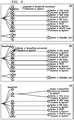
- FIG. 4shows an example of form dependency management in an illustrative embodiment of the invention.
- FIG. 4depicts a hierarchy 402 wherein each node is enabled as being able to be dragged. Additionally, hierarchy 404 depicts attaching a selected node to a desired dependency hierarchy, hierarchy 406 depicts an updated dependency rule in the form based on the dragged-and-dropped node mechanism illustrated in hierarchies 402 and 404 .
- At least one embodiment of the inventionincludes identifying and displaying unreachable dependency components in the given form.
- a use case of unreachable dependency componentscan occur when multiple dependencies are applied to a form component, and there is no path available to the user to reach and/or display that form component. This can also occur, for example, in a case of dependency chaining and multiple show/hide rules.
- one or more embodiments of the inventioncan include introducing unreachable dependency while designing forms and displaying the forms in the hierarchal structure with highlighting.
- Such an embodimentcan include, for example, adding, via the form designer, a radio button component and a text area component, and applying a show/hide rule on the text area with multiple conditions.
- the text area componentbecomes unreachable regardless of the value of the radio button (Yes, No), and consequently, the text area component will never be displayed in the form user interface (UI).
- one or more embodiments of the inventioncan include highlighting, in the hierarchical structure, the text field as an unreachable dependency.
- the updated (dependency hierarchy) designcan be saved/stored in a graph database ( 204 ) using persistence service 134 , and can also be utilized to update the actual form in the presentation layer.
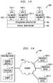
- FIG. 5shows system architecture on a multi-cloud application platform in an illustrative embodiment of the invention.
- FIG. 5depicts user device 102 - 1 (implementing a form designer application) interacting with a cloud-hosted platform 502 .
- the cloud-hosted platform 502includes a cloud platform controller component 504 , which is used to direct the deployment of the form designer application.
- the cloud-hosted platform 502includes a cloud platform router component 506 , which is used to route the incoming user requests to one or more appropriate components within the cloud-hosted platform 502 .
- the cloud-hosted platform 502includes a cloud platform health manager component 508 , which monitors the health status of the form designer application, and also includes a distributed queueing and messaging system 510 of the cloud-hosted platform 502 .
- the cloud-hosted platform 502additionally includes a collection of cloud platform services 512 , which can be used for application logging, monitoring, session management, etc.
- the cloud-hosted platform 502includes an execution agent 514 , which can be used to design the form (via the form design application) using a drag-and-drop interface and updated form dependency (show-hide) rules. As illustrated in FIG.
- the execution agent 514interacts with the EFDVM system 105 , which interacts with a collection of user-provided services 516 that can operate in conjunction with additional components such as one or more databases 520 used to store documents in network-attached storage (NAS), an NoSQL database 518 to store form designs, and a graph database 204 to store the hierarchal structure.
- additional componentssuch as one or more databases 520 used to store documents in network-attached storage (NAS), an NoSQL database 518 to store form designs, and a graph database 204 to store the hierarchal structure.
- one or more embodiments of the inventioninclude development and implementation of Java classes (such as depicted in FIG. 6 through FIG. 11 ) to transform JSON based schema to a tree/graphical hierarchy of dynamic forms with capabilities such as detailed herein.
- FIG. 6shows an association class diagram for a form designer micro-service in an illustrative embodiment of the invention.
- various Java classescan be utilized in the EFDVM system 105 .
- Such Java classescan include, for example, a local product class 602 , a product class 604 , a product name class 606 , an attachment class 608 , a product category class 610 , a product template class 612 , and a product ID class 614 .
- the local product class 602(ProductLocal) is used to store the non-published presentation layer JSON data comprising its structure and values.
- the product class 604(Product) is used to store the published and approved version of the presentation layer with revision specifications along with structure and value details of the presentation layer.
- the product name class 606(ProductName) is used to store the name of the designed content
- the attachment class 608(Attachment) is used to store attachment-related metadata information
- the product category class 610(ProductCategory) is used to distinguish the generated contents category.
- product template class 612(TemplateProduct) is used to generate the template information utilized by a free marker templates engine
- product ID class 614ProductId is a super class of Product, ProductLocal and TemplateProduct for uniquely identifying the stored JSON schema structure ID.
- FIG. 7shows a controller and repository association class diagram for a form designer micro-service in an illustrative embodiment of the invention.
- various Java classescan be utilized in the EFDVM system 105 .
- Such Java classescan include, for example, a product category controller class 702 , a product category repository class 704 , a product designer controller class 706 , a product type mapping repository class 708 , a product repository class 710 , a product name repository class 712 , and a local product repository class 714 .
- the product category controller class 702stores the designed presentation layer category
- the product category repository class 704(ProductCategoryRepository) relates to an interface establishing a contract for interfacing with an NoSQL database to store the designed presentation layer category
- the product designer controller class 706(ProductDesignerController) provides implementation classes of a product micro-service written using the Spring boot technology framework, and provides generic implementation of end points and business logics that govern the publish and design process from the enterprise services framework for presentation layer management.
- the product type mapping repository class 708(ProjectTypeMappingRepository) relates to an interface establishing a contract for interfacing with an NoSQL database
- the product repository class 710(ProductRepository) relates to an interface establishing a contract for interfacing with an NoSQL database linking designed presentation layer content with its category.
- the product name repository class 712(ProductNameRepository) relates to an interface establishing a contract for interfacing with an NoSQL database to store the names of the designed presentation layer data
- the local product repository class 714(ProductLocalRepository) relates to an interface establishing a contract for interfacing with an NoSQL database for non-published presentation layer content.
- FIG. 8shows a class association diagram for a visualization micro-service in an illustrative embodiment of the invention.
- various Java classescan be utilized in the EFDVM system 105 .
- Such Java classescan include, for example, a local product class 802 , a product class 804 , a product ID class 806 , a tree class 808 , and a component class 810 .
- the local product class 802(ProductLocal) is used to store the non-published presentation layer JSON data comprising its structure and values
- the product class 804(Product) is used to store the published and approved version of the presentation layer with revision specifications along with structure and value details of presentation layer.
- the product ID class 806(ProductId) is a super class of Product, ProductLocal and TemplateProduct for uniquely identifying the stored JSON schema structure ID.
- the tree class 808(TreeBean) is used to store the transformed hierarchal structure of presentation layer JSON data
- the component class 810(ComponentBean) is a super class of TreeBean used to store metadata information of the transformed hierarchal structure.
- FIG. 9shows a controller and repository association diagram for a visualization micro-service in an illustrative embodiment of the invention.
- various Java classescan be utilized in the EFDVM system 105 .
- Such Java classescan include, for example, a visual form service application class 902 , a servlet initializer class 904 , a product repository class 906 , a home controller class 908 , a visual controller class 910 , a local product repository class 912 , and a visual tree class 914 .
- the visual form service application class 902(AdVisualFormServiceApplication) provides a convenient way to bootstrap and launch a visual micro-service
- the servlet initializer class 904(ServletInitializer) is a Java class extending the SpringBootServletlnitializer class, which allows configuration of the visual micro-service by overriding the configure method.
- the product repository class 906(ProductRepository) relates to an interface establishing a contract for interfacing with an NoSQL database of approved and published presentation layer content
- the home controller class 908(HomeController) provides a representational state transfer (REST) end-point to an interface with the view of the visualization micro-service.
- RESTrepresentational state transfer
- the visual controller class 910(VisualController) provides a generic API end-point for converting JSON data of the presentation layer to a hierarchal structure
- the local product repository class 912(ProductLocalRepository) relates to an interface establishing a contract for interfacing with an NoSQL database of non-published presentation layer content
- the visual tree class 914(VisualTree) is a Spring component class that provides the implementation of transforming the presentation layer JSON data to a hierarchal structure.
- FIG. 10shows a class association diagram for a persistence micro-service in an illustrative embodiment of the invention.
- various Java classescan be utilized in the EFDVM system 105 .
- Such Java classescan include, for example, a tree class 1002 , and a component class 1004 .
- the tree class 1002(TreeBean) is used to store the transformed hierarchal structure of presentation layer JSON data
- component class 1004is a super class of TreeBean used to store metadata information of the transformed hierarchal structure.
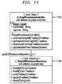
- FIG. 11shows a controller and repository association class diagram for a persistence micro-service in an illustrative embodiment of the invention.
- various Java classescan be utilized in the EFDVM system 105 .
- Such Java classescan include, for example, a graph persistence controller class 1102 , and a graph database persistence repository class 1104 .
- the graph persistence controller class 1102(GraphPersistanceController) provides implementation of the persistence micro-service to save the hierarchal data in a graph database
- the graph database persistence repository class 1104(GraphDBPersistanceRepository) relates to an interface establishing a contract for interfacing with a graph database to store the transformed hierarchal structure of presentation layer.
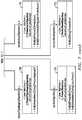
- FIG. 12is a flow diagram of a process for application development via presentation layer management in an illustrative embodiment. It is to be understood that this particular process is only an example, and additional or alternative processes can be carried out in other embodiments.
- the processincludes steps 1200 through 1208 . These steps are assumed to be performed by the processor 120 utilizing its modules 130 , 132 , and 134 .
- Step 1200includes transforming an enterprise form from a given format into a hierarchical representation.
- the given formatcan include, for example, a JAVASCRIPT object notation format.
- Transforming the enterprise formcan include rendering the hierarchical representation using an extensible markup language-based vector image format.
- at least one embodiment of the inventionincludes storing the hierarchal representation in a graph database via a persistence service.
- Step 1202includes generating a visualization of a set of one or more configurable form dependencies within the hierarchical representation.
- Generating the visualizationcan include detecting one or more unreachable dependencies within the enterprise form. Additionally, detecting the one or more unreachable dependencies can include performing link analysis on the enterprise form. Also, at least one embodiment of the invention includes outputting the generated visualization to one or more web browsers associated with the user.
- Step 1204includes updating, in response to user input, the visualization of the set of one or more configurable form dependencies.
- the user inputcan include, for example, dragging and dropping of one or more nodes within the hierarchical representation, wherein the one or more nodes represent one or more of the configurable form dependencies.
- Step 1206includes generating an updated version of the enterprise form by modifying, in response to updating the visualization of the set of one or more configurable form dependencies, one or more form dependency rules of the enterprise form in a presentation layer associated with the enterprise form.
- the one or more form dependency rulescan include one or more elements of conditional logic.
- Step 1208includes dynamically outputting the updated version of the enterprise form to at least one user. Additionally, at least one embodiment of the invention includes storing the updated version of the enterprise form in a graph database via a persistence service.
- processing operations and other functionality described in conjunction with the flow diagram of FIG. 12are presented by way of illustrative example only, and should not be construed as limiting the scope of the invention in any way.
- Alternative embodimentscan use other types of processing operations to detect session-based access anomalies and undertake appropriate remediation actions.
- the ordering of the process stepsmay be varied in other embodiments, or certain steps may be performed concurrently with one another rather than serially.
- the process steps or subsets thereofmay be repeated periodically in conjunction with respective distinct instances of session-based anomaly detection for different user identifiers.
- one or more embodiments of the inventionprovide significant advantages relative to conventional approaches.
- one or more embodiments of the inventioninclude providing the ability to view and update form dependencies via a single screen with graphical representation, as well as enabling users to add and/or update conditional logics within the graphical representation via a drag-and-drop mechanism.
- a given such processing platformcomprises at least one processing device comprising a processor coupled to a memory.
- the processor and memoryin some embodiments comprise respective processor and memory elements of a virtual machine or container provided using one or more underlying physical machines.
- the term “processing device” as used hereinis intended to be broadly construed so as to encompass a wide variety of different arrangements of physical processors, memories and other device components as well as virtual instances of such components.
- a “processing device” in some embodimentscan comprise or be executed across one or more virtual processors. Processing devices can therefore be physical or virtual and can be executed across one or more physical or virtual processors. It should also be noted that a given virtual device can be mapped to a portion of a physical one.
- the cloud infrastructurefurther comprises sets of applications running on respective ones of the virtual machines under the control of the hypervisor. It is also possible to use multiple hypervisors each providing a set of virtual machines using at least one underlying physical machine. Different sets of virtual machines provided by one or more hypervisors may be utilized in configuring multiple instances of various components of the system.
- cloud infrastructurecan be used to provide what is also referred to herein as a multi-tenant environment.
- One or more system components, or portions thereof,are illustratively implemented for use by tenants of such a multi-tenant environment.
- cloud infrastructureas disclosed herein can include cloud-based systems such as AMAZON WEB SERVICES (AWS), GOOGLE Cloud Platform (GCP) and MICROSOFT Azure.
- Virtual machinesprovided in such systems can be used to implement at least portions of one or more of a computer system and a content addressable storage system in illustrative embodiments.
- object storessuch as AMAZON S3, GCP Cloud Storage, and MICROSOFT Azure Blob Storage.
- the cloud infrastructureadditionally or alternatively comprises a plurality of containers implemented using container host devices.
- a given container of cloud infrastructureillustratively comprises a Docker container or other type of Linux Container (LXC).
- LXCLinux Container
- the containersmay run on virtual machines in a multi-tenant environment, although other arrangements are possible.
- the containersmay be utilized to implement a variety of different types of functionality within the system 100 .
- containerscan be used to implement respective processing devices providing compute and/or storage services of a cloud-based system.
- containersmay be used in combination with other virtualization infrastructure such as virtual machines implemented using a hypervisor.
- processing platformswill now be described in greater detail with reference to FIGS. 13 and 14 . Although described in the context of system 100 , these platforms may also be used to implement at least portions of other information processing systems in other embodiments.
- FIG. 13shows an example processing platform comprising cloud infrastructure 1300 .
- the cloud infrastructure 1300comprises a combination of physical and virtual processing resources that may be utilized to implement at least a portion of the information processing system 100 .
- the cloud infrastructure 1300comprises multiple virtual machines (VMs) and/or container sets 1302 - 1 , 1302 - 2 , . . . 1302 -L implemented using virtualization infrastructure 1304 .
- the virtualization infrastructure 1304runs on physical infrastructure 1305 , and illustratively comprises one or more hypervisors and/or operating system level virtualization infrastructure.
- the operating system level virtualization infrastructureillustratively comprises kernel control groups of a Linux operating system or other type of operating system.
- the cloud infrastructure 1300further comprises sets of applications 1310 - 1 , 1310 - 2 , . . . 1310 -L running on respective ones of the VMs/container sets 1302 - 1 , 1302 - 2 , . . . 1302 -L under the control of the virtualization infrastructure 1304 .
- the VMs/container sets 1302may comprise respective VMs, respective sets of one or more containers, or respective sets of one or more containers running in VMs.
- the VMs/container sets 1302comprise respective VMs implemented using virtualization infrastructure 1304 that comprises at least one hypervisor.
- virtualization infrastructure 1304that comprises at least one hypervisor.
- An example of a hypervisor platform that may be used to implement a hypervisor within the virtualization infrastructure 1304is the VMware® vSphere® which may have an associated virtual infrastructure management system such as the VMware® vCenterTM.
- the underlying physical machinesmay comprise one or more distributed processing platforms that include one or more storage systems.
- the VMs/container sets 1302comprise respective containers implemented using virtualization infrastructure 1304 that provides operating system level virtualization functionality, such as support for Docker containers running on bare metal hosts, or Docker containers running on VMs.
- the containersare illustratively implemented using respective kernel control groups of the operating system.
- one or more of the processing modules or other components of system 100may each run on a computer, server, storage device or other processing platform element.
- a given such elementmay be viewed as an example of what is more generally referred to herein as a “processing device.”
- the cloud infrastructure 1300 shown in FIG. 13may represent at least a portion of one processing platform.
- processing platform 1400 shown in FIG. 14is another example of such a processing platform.
- the processing platform 1400 in this embodimentcomprises a portion of system 100 and includes a plurality of processing devices, denoted 1402 - 1 , 1402 - 2 , 1402 - 3 , . . . 1402 -K, which communicate with one another over a network 1404 .
- the network 1404may comprise any type of network, including by way of example a global computer network such as the Internet, a WAN, a LAN, a satellite network, a telephone or cable network, a cellular network, a wireless network such as a Wi-Fi or WiMAX network, or various portions or combinations of these and other types of networks.
- the processing device 1402 - 1 in the processing platform 1400comprises a processor 1410 coupled to a memory 1412 .
- the processor 1410may comprise a microprocessor, a microcontroller, an application-specific integrated circuit (ASIC), a field-programmable gate array (FPGA) or other type of processing circuitry, as well as portions or combinations of such circuitry elements.
- ASICapplication-specific integrated circuit
- FPGAfield-programmable gate array
- the memory 1412may comprise random access memory (RAM), read-only memory (ROM) or other types of memory, in any combination.
- RAMrandom access memory
- ROMread-only memory
- the memory 1412 and other memories disclosed hereinshould be viewed as illustrative examples of what are more generally referred to as “processor-readable storage media” storing executable program code of one or more software programs.
- Articles of manufacturecomprising such processor-readable storage media are considered illustrative embodiments.
- a given such article of manufacturemay comprise, for example, a storage array, a storage disk or an integrated circuit containing RAM, ROM or other electronic memory, or any of a wide variety of other types of computer program products.
- the term “article of manufacture” as used hereinshould be understood to exclude transitory, propagating signals. Numerous other types of computer program products comprising processor-readable storage media can be used.
- network interface circuitry 1414which is used to interface the processing device with the network 1404 and other system components, and may comprise conventional transceivers.
- the other processing devices 1402 of the processing platform 1400are assumed to be configured in a manner similar to that shown for processing device 1402 - 1 in the figure.
- processing platform 1400 shown in the figureis presented by way of example only, and system 100 may include additional or alternative processing platforms, as well as numerous distinct processing platforms in any combination, with each such platform comprising one or more computers, servers, storage devices or other processing devices.
- processing platforms used to implement illustrative embodimentscan comprise different types of virtualization infrastructure, in place of or in addition to virtualization infrastructure comprising virtual machines.
- virtualization infrastructureillustratively includes container-based virtualization infrastructure configured to provide Docker containers or other types of LXCs.
- portions of a given processing platform in some embodimentscan comprise converged infrastructure such as VxRailTM, VxRackTM, VxBlockTM, or Vblock® converged infrastructure commercially available from VCE, the Virtual Computing Environment Company, now the Converged Platform and Solutions Division of DELL EMC.
- VxRailTM, VxRackTM, VxBlockTM, or Vblock®converged infrastructure commercially available from VCE, the Virtual Computing Environment Company, now the Converged Platform and Solutions Division of DELL EMC.
- particular types of storage productsthat can be used in implementing a given storage system of a distributed processing system in an illustrative embodiment include VNX® and Symmetrix VMAX® storage arrays, software-defined storage products such as ScaleIOTM and ViPR®, all-flash and hybrid flash storage arrays such as UnityTM, cloud storage products such as Elastic Cloud Storage (ECS), object-based storage products such as Atmos®, scale-out all-flash storage arrays such as XtremIOTM, and scale-out NAS clusters comprising Isilon® platform nodes and associated accelerators, all from DELL EMC. Combinations of multiple ones of these and other storage products can also be used in implementing a given storage system in an illustrative embodiment.
Landscapes
- Engineering & Computer Science (AREA)
- Theoretical Computer Science (AREA)
- Physics & Mathematics (AREA)
- General Engineering & Computer Science (AREA)
- General Physics & Mathematics (AREA)
- Audiology, Speech & Language Pathology (AREA)
- Computational Linguistics (AREA)
- General Health & Medical Sciences (AREA)
- Health & Medical Sciences (AREA)
- Artificial Intelligence (AREA)
- Databases & Information Systems (AREA)
- Software Systems (AREA)
- Data Mining & Analysis (AREA)
- Stored Programmes (AREA)
Abstract
Description
Claims (20)
Priority Applications (1)
| Application Number | Priority Date | Filing Date | Title |
|---|---|---|---|
| US16/177,993US10740537B2 (en) | 2018-11-01 | 2018-11-01 | Enterprise form dependency visualization and management |
Applications Claiming Priority (1)
| Application Number | Priority Date | Filing Date | Title |
|---|---|---|---|
| US16/177,993US10740537B2 (en) | 2018-11-01 | 2018-11-01 | Enterprise form dependency visualization and management |
Publications (2)
| Publication Number | Publication Date |
|---|---|
| US20200142953A1 US20200142953A1 (en) | 2020-05-07 |
| US10740537B2true US10740537B2 (en) | 2020-08-11 |
Family
ID=70459602
Family Applications (1)
| Application Number | Title | Priority Date | Filing Date |
|---|---|---|---|
| US16/177,993ActiveUS10740537B2 (en) | 2018-11-01 | 2018-11-01 | Enterprise form dependency visualization and management |
Country Status (1)
| Country | Link |
|---|---|
| US (1) | US10740537B2 (en) |
Cited By (1)
| Publication number | Priority date | Publication date | Assignee | Title |
|---|---|---|---|---|
| US11223522B1 (en)* | 2021-01-15 | 2022-01-11 | Dell Products L.P. | Context-based intelligent re-initiation of microservices |
Families Citing this family (7)
| Publication number | Priority date | Publication date | Assignee | Title |
|---|---|---|---|---|
| US11138194B2 (en)* | 2019-04-02 | 2021-10-05 | International Business Machines Corporation | Method of extracting relationships from a NoSQL database |
| US11748458B2 (en)* | 2020-04-15 | 2023-09-05 | Codelogic, Inc. | Systems and methods for a governance engine |
| US11308267B1 (en)* | 2020-09-25 | 2022-04-19 | UiPath, Inc. | Artifacts reference creation and dependency tracking |
| US11204961B1 (en)* | 2020-09-29 | 2021-12-21 | Atlassian Pty Ltd. | Apparatuses, methods, and computer program products for dynamic generation and traversal of object dependency data structures |
| CN113641700B (en)* | 2021-08-30 | 2025-02-21 | 北京沃东天骏信息技术有限公司 | A data processing method and device based on Spring boot framework |
| CN114185623B (en)* | 2021-12-20 | 2024-04-19 | 中国工商银行股份有限公司 | Processing method and device for deadlock in application starting process |
| USD1086155S1 (en)* | 2023-03-20 | 2025-07-29 | Daniel Yarovoy | Display screen or portion thereof with a graphical user interface of a hierarchal tree |
Citations (61)
| Publication number | Priority date | Publication date | Assignee | Title |
|---|---|---|---|---|
| US5689711A (en)* | 1995-04-21 | 1997-11-18 | Bardasz; Theodore | Method and apparatus for representing data dependencies in software modeling systems |
| US6359637B1 (en)* | 1999-02-05 | 2002-03-19 | International Busines Machines Corp. | Drill-down apparatus for display of tree-based hierarchies and method therefor |
| US20020059334A1 (en)* | 1999-05-07 | 2002-05-16 | Richard Jelbert | Graphical data within documents |
| US20020099732A1 (en)* | 2000-12-06 | 2002-07-25 | Miller Daniel J. | Interface and related methods for dynamically generating a filter graph in a development system |
| US20020156814A1 (en)* | 1997-01-13 | 2002-10-24 | Ho Bruce K. | Method and apparatus for visual business computing |
| US20030067481A1 (en)* | 2001-03-31 | 2003-04-10 | Christopher Chedgey | System and method for computer-aided graph-based dependency analysis with integrated documentation |
| US20030176999A1 (en)* | 2002-01-14 | 2003-09-18 | Calcagno Michael V. | Semantic analysis system for interpreting linguistic structures output by a natural language linguistic analysis system |
| US6704454B1 (en)* | 1999-07-23 | 2004-03-09 | Sarnoff Corporation | Method and apparatus for image processing by generating probability distribution of images |
| US6922807B1 (en)* | 1999-01-29 | 2005-07-26 | Canon Kabushiki Kaisha | Object editing apparatus and method, and recording medium storing computer-readable program |
| US7065717B1 (en)* | 1999-01-19 | 2006-06-20 | International Business Machines Corporation | Tree-based interface apparatus for display of call dependencies and method therefor |
| US20060155700A1 (en)* | 2005-01-10 | 2006-07-13 | Xerox Corporation | Method and apparatus for structuring documents based on layout, content and collection |
| US20060277231A1 (en) | 2005-06-06 | 2006-12-07 | Javaground Usa, Inc. | Integrated software development and porting system for wireless devices |
| US20070079282A1 (en) | 2005-09-30 | 2007-04-05 | Pawan Nachnani | Browser based designer and player |
| US7281018B1 (en)* | 2004-05-26 | 2007-10-09 | Microsoft Corporation | Form template data source change |
| US20070245231A1 (en)* | 2006-04-18 | 2007-10-18 | Kibler Wendell L | Optimization of storage and delivery of markup language files |
| US20070266368A1 (en)* | 2006-05-12 | 2007-11-15 | The Mathworks, Inc. | System and method for synchronized workflow management |
| US7509244B1 (en)* | 2004-12-22 | 2009-03-24 | The Mathworks, Inc. | Distributed model compilation |
| US20090217248A1 (en)* | 2008-02-12 | 2009-08-27 | Bently William G | Systems and methods for information flow analysis |
| US20090240483A1 (en) | 2008-03-19 | 2009-09-24 | International Business Machines Corporation | System and computer program product for automatic logic model build process with autonomous quality checking |
| US20100058164A1 (en)* | 2008-08-27 | 2010-03-04 | International Business Machines Corporation | Property dependency visualization |
| US20100079462A1 (en)* | 2008-10-01 | 2010-04-01 | International Business Machines Corporation | method and system for generating and displaying an interactive dynamic view of bi-directional impact analysis results for multiply connected objects |
| US7716179B1 (en)* | 2009-10-29 | 2010-05-11 | Wowd, Inc. | DHT-based distributed file system for simultaneous use by millions of frequently disconnected, world-wide users |
| US20100211754A1 (en)* | 2009-02-13 | 2010-08-19 | Crosby Peter Anthony | Memory utilization analysis |
| US20110066934A1 (en)* | 2009-09-15 | 2011-03-17 | Avoka Technologies Pty Ltd | Generation of electronic forms |
| US20110289425A1 (en)* | 2010-05-20 | 2011-11-24 | Salesforce.Com, Inc. | Methods and systems for providing a user interface in a multi-tenant database environment |
| US8122050B2 (en) | 2008-04-16 | 2012-02-21 | International Business Machines Corporation | Query processing visualization system and method of visualizing query processing |
| US20120066586A1 (en)* | 2010-09-07 | 2012-03-15 | Yaniv Shemesh | Systems and methods for accelerating web page loading |
| US8307109B2 (en) | 2003-08-27 | 2012-11-06 | International Business Machines Corporation | Methods and systems for real time integration services |
| US20130152078A1 (en) | 2011-12-09 | 2013-06-13 | Yahoo! Inc. | Method and system for deploying multiple distributed application stacks on a target machine |
| US8478616B2 (en) | 2004-10-29 | 2013-07-02 | FrontRange Solutions USA Inc. | Business application development and execution environment |
| US20130332241A1 (en) | 2011-09-29 | 2013-12-12 | James Taylor | System and Method for Decision-Driven Business Performance Measurement |
| US20140006991A1 (en)* | 2010-06-24 | 2014-01-02 | Adobe Systems Incorporated | Displaying graphical indications to indicate dependencies between scripts |
| US20140032480A1 (en)* | 2007-09-04 | 2014-01-30 | Daniel Lesage | Form template refactoring |
| US8706667B2 (en)* | 2007-07-26 | 2014-04-22 | Ab Initio Technology Llc | Transactional graph-based computation with error handling |
| US20140123061A1 (en)* | 2012-10-31 | 2014-05-01 | General Electric Company | Surfacing of detailed information via formlets |
| US8719066B2 (en) | 2010-08-17 | 2014-05-06 | Edifice Technologies Inc. | Systems and methods for capturing, managing, sharing, and visualising asset information of an organization |
| US20140143763A1 (en) | 2012-10-29 | 2014-05-22 | Harsh Bhargava | Method and System to develop operating system agnostic software applications for mobile devices using a virtual machine |
| US20140279976A1 (en) | 2013-03-15 | 2014-09-18 | Sony Pictures Technologies Inc. | Method and system for recording information about rendered assets |
| US8856724B2 (en) | 2011-06-20 | 2014-10-07 | Ebay Inc. | Systems and methods for incremental software development |
| US8863069B1 (en)* | 2006-09-11 | 2014-10-14 | The Mathworks, Inc. | Hardware definition language generation for data serialization from executable graphical models |
| US20140317045A1 (en) | 2011-05-12 | 2014-10-23 | Google Inc. | Data model generation based on user interface specification |
| US20160092525A1 (en) | 2014-09-26 | 2016-03-31 | Oracle International Corporation | Integrating object-based data integration tool with a version control system in centralized and decentralized environments |
| US9329838B2 (en) | 2003-09-11 | 2016-05-03 | Open Text S.A. | User-friendly data binding, such as drag-and-drop data binding in a workflow application |
| US20160291942A1 (en)* | 2012-10-20 | 2016-10-06 | Luke Hutchison | Systems and methods for parallelization of program code, interactive data visualization, and graphically-augmented code editing |
| US20160321234A1 (en)* | 2015-04-28 | 2016-11-03 | Box, Inc. | Composition and declaration of sprited images in a web page style sheet |
| US20170097927A1 (en)* | 2014-04-17 | 2017-04-06 | Hewlett Packard Enterprise Development Lp | Cascading style sheet meta language performance |
| US9619445B1 (en)* | 2012-08-23 | 2017-04-11 | Inkling Systems, Inc. | Conversion of content to formats suitable for digital distributions thereof |
| US20170115968A1 (en) | 2015-10-23 | 2017-04-27 | Oracle International Corporation | Application builder with automated data objects creation |
| US20170124617A1 (en) | 2014-06-02 | 2017-05-04 | Dgit Consultants Pty Ltd | Telecommunications product defining and provisioning |
| US20170270037A1 (en) | 2016-03-18 | 2017-09-21 | Salesforce.Com, Inc. | Making production data available for testing in a non-production environment |
| US20180081645A1 (en) | 2016-09-16 | 2018-03-22 | Oracle International Corporation | Generic-flat structure rest api editor |
| US10019239B2 (en) | 2003-09-11 | 2018-07-10 | Open Text Sa Ulc | Systems and methods for enhancing software products through integrated development environment running on host computer |
| US20180232648A1 (en)* | 2017-02-14 | 2018-08-16 | Cognitive Scale, Inc. | Navigating a Hierarchical Abstraction of Topics via an Augmented Gamma Belief Network Operation |
| US20180232456A1 (en) | 2017-02-14 | 2018-08-16 | Brian Arthur Sherman | System for creating data-connected applications |
| US20180247243A1 (en) | 2017-02-21 | 2018-08-30 | Sourcecode Technology Holdings, Inc. | Collaborative design systems, apparatuses, and methods |
| US20180253296A1 (en) | 2015-10-30 | 2018-09-06 | Hewlett Packard Enterprise Development Lp | Software kit release management |
| US20180321831A1 (en) | 2017-05-08 | 2018-11-08 | Sap Se | Smart controls for user interface design and implementation |
| US10305758B1 (en)* | 2014-10-09 | 2019-05-28 | Splunk Inc. | Service monitoring interface reflecting by-service mode |
| US10318285B1 (en) | 2017-08-16 | 2019-06-11 | Amazon Technologies, Inc. | Deployment of infrastructure in pipelines |
| US20190236226A1 (en)* | 2016-07-21 | 2019-08-01 | Nec Corporation | Estimated distance calculator, estimated distance calculation method, estimated distance calculation program, and automated planner |
| US20190361686A1 (en)* | 2018-05-24 | 2019-11-28 | Find it EZ Software Corp. | Methods, systems, apparatuses and devices for facilitating change impact analysis (cia) using modular program dependency graphs |
- 2018
- 2018-11-01USUS16/177,993patent/US10740537B2/enactiveActive
Patent Citations (63)
| Publication number | Priority date | Publication date | Assignee | Title |
|---|---|---|---|---|
| US5689711A (en)* | 1995-04-21 | 1997-11-18 | Bardasz; Theodore | Method and apparatus for representing data dependencies in software modeling systems |
| US20020156814A1 (en)* | 1997-01-13 | 2002-10-24 | Ho Bruce K. | Method and apparatus for visual business computing |
| US7065717B1 (en)* | 1999-01-19 | 2006-06-20 | International Business Machines Corporation | Tree-based interface apparatus for display of call dependencies and method therefor |
| US6922807B1 (en)* | 1999-01-29 | 2005-07-26 | Canon Kabushiki Kaisha | Object editing apparatus and method, and recording medium storing computer-readable program |
| US6359637B1 (en)* | 1999-02-05 | 2002-03-19 | International Busines Machines Corp. | Drill-down apparatus for display of tree-based hierarchies and method therefor |
| US20020059334A1 (en)* | 1999-05-07 | 2002-05-16 | Richard Jelbert | Graphical data within documents |
| US6704454B1 (en)* | 1999-07-23 | 2004-03-09 | Sarnoff Corporation | Method and apparatus for image processing by generating probability distribution of images |
| US20020099732A1 (en)* | 2000-12-06 | 2002-07-25 | Miller Daniel J. | Interface and related methods for dynamically generating a filter graph in a development system |
| US20030067481A1 (en)* | 2001-03-31 | 2003-04-10 | Christopher Chedgey | System and method for computer-aided graph-based dependency analysis with integrated documentation |
| US20030176999A1 (en)* | 2002-01-14 | 2003-09-18 | Calcagno Michael V. | Semantic analysis system for interpreting linguistic structures output by a natural language linguistic analysis system |
| US8307109B2 (en) | 2003-08-27 | 2012-11-06 | International Business Machines Corporation | Methods and systems for real time integration services |
| US9329838B2 (en) | 2003-09-11 | 2016-05-03 | Open Text S.A. | User-friendly data binding, such as drag-and-drop data binding in a workflow application |
| US10019239B2 (en) | 2003-09-11 | 2018-07-10 | Open Text Sa Ulc | Systems and methods for enhancing software products through integrated development environment running on host computer |
| US7281018B1 (en)* | 2004-05-26 | 2007-10-09 | Microsoft Corporation | Form template data source change |
| US8478616B2 (en) | 2004-10-29 | 2013-07-02 | FrontRange Solutions USA Inc. | Business application development and execution environment |
| US7509244B1 (en)* | 2004-12-22 | 2009-03-24 | The Mathworks, Inc. | Distributed model compilation |
| US20060155700A1 (en)* | 2005-01-10 | 2006-07-13 | Xerox Corporation | Method and apparatus for structuring documents based on layout, content and collection |
| US7693848B2 (en)* | 2005-01-10 | 2010-04-06 | Xerox Corporation | Method and apparatus for structuring documents based on layout, content and collection |
| US20060277231A1 (en) | 2005-06-06 | 2006-12-07 | Javaground Usa, Inc. | Integrated software development and porting system for wireless devices |
| US20070079282A1 (en) | 2005-09-30 | 2007-04-05 | Pawan Nachnani | Browser based designer and player |
| US20070245231A1 (en)* | 2006-04-18 | 2007-10-18 | Kibler Wendell L | Optimization of storage and delivery of markup language files |
| US20070266368A1 (en)* | 2006-05-12 | 2007-11-15 | The Mathworks, Inc. | System and method for synchronized workflow management |
| US8863069B1 (en)* | 2006-09-11 | 2014-10-14 | The Mathworks, Inc. | Hardware definition language generation for data serialization from executable graphical models |
| US8706667B2 (en)* | 2007-07-26 | 2014-04-22 | Ab Initio Technology Llc | Transactional graph-based computation with error handling |
| US20140032480A1 (en)* | 2007-09-04 | 2014-01-30 | Daniel Lesage | Form template refactoring |
| US20090217248A1 (en)* | 2008-02-12 | 2009-08-27 | Bently William G | Systems and methods for information flow analysis |
| US20090240483A1 (en) | 2008-03-19 | 2009-09-24 | International Business Machines Corporation | System and computer program product for automatic logic model build process with autonomous quality checking |
| US8122050B2 (en) | 2008-04-16 | 2012-02-21 | International Business Machines Corporation | Query processing visualization system and method of visualizing query processing |
| US20100058164A1 (en)* | 2008-08-27 | 2010-03-04 | International Business Machines Corporation | Property dependency visualization |
| US20100079462A1 (en)* | 2008-10-01 | 2010-04-01 | International Business Machines Corporation | method and system for generating and displaying an interactive dynamic view of bi-directional impact analysis results for multiply connected objects |
| US20100211754A1 (en)* | 2009-02-13 | 2010-08-19 | Crosby Peter Anthony | Memory utilization analysis |
| US20110066934A1 (en)* | 2009-09-15 | 2011-03-17 | Avoka Technologies Pty Ltd | Generation of electronic forms |
| US7716179B1 (en)* | 2009-10-29 | 2010-05-11 | Wowd, Inc. | DHT-based distributed file system for simultaneous use by millions of frequently disconnected, world-wide users |
| US20110289425A1 (en)* | 2010-05-20 | 2011-11-24 | Salesforce.Com, Inc. | Methods and systems for providing a user interface in a multi-tenant database environment |
| US20140006991A1 (en)* | 2010-06-24 | 2014-01-02 | Adobe Systems Incorporated | Displaying graphical indications to indicate dependencies between scripts |
| US8719066B2 (en) | 2010-08-17 | 2014-05-06 | Edifice Technologies Inc. | Systems and methods for capturing, managing, sharing, and visualising asset information of an organization |
| US20120066586A1 (en)* | 2010-09-07 | 2012-03-15 | Yaniv Shemesh | Systems and methods for accelerating web page loading |
| US20140317045A1 (en) | 2011-05-12 | 2014-10-23 | Google Inc. | Data model generation based on user interface specification |
| US8856724B2 (en) | 2011-06-20 | 2014-10-07 | Ebay Inc. | Systems and methods for incremental software development |
| US20130332241A1 (en) | 2011-09-29 | 2013-12-12 | James Taylor | System and Method for Decision-Driven Business Performance Measurement |
| US20150142726A1 (en) | 2011-09-29 | 2015-05-21 | Decision Management Solutions | System and Method for Decision Driven Business Performance Management |
| US20130152078A1 (en) | 2011-12-09 | 2013-06-13 | Yahoo! Inc. | Method and system for deploying multiple distributed application stacks on a target machine |
| US9619445B1 (en)* | 2012-08-23 | 2017-04-11 | Inkling Systems, Inc. | Conversion of content to formats suitable for digital distributions thereof |
| US20160291942A1 (en)* | 2012-10-20 | 2016-10-06 | Luke Hutchison | Systems and methods for parallelization of program code, interactive data visualization, and graphically-augmented code editing |
| US20140143763A1 (en) | 2012-10-29 | 2014-05-22 | Harsh Bhargava | Method and System to develop operating system agnostic software applications for mobile devices using a virtual machine |
| US20140123061A1 (en)* | 2012-10-31 | 2014-05-01 | General Electric Company | Surfacing of detailed information via formlets |
| US20140279976A1 (en) | 2013-03-15 | 2014-09-18 | Sony Pictures Technologies Inc. | Method and system for recording information about rendered assets |
| US20170097927A1 (en)* | 2014-04-17 | 2017-04-06 | Hewlett Packard Enterprise Development Lp | Cascading style sheet meta language performance |
| US20170124617A1 (en) | 2014-06-02 | 2017-05-04 | Dgit Consultants Pty Ltd | Telecommunications product defining and provisioning |
| US20160092525A1 (en) | 2014-09-26 | 2016-03-31 | Oracle International Corporation | Integrating object-based data integration tool with a version control system in centralized and decentralized environments |
| US10305758B1 (en)* | 2014-10-09 | 2019-05-28 | Splunk Inc. | Service monitoring interface reflecting by-service mode |
| US20160321234A1 (en)* | 2015-04-28 | 2016-11-03 | Box, Inc. | Composition and declaration of sprited images in a web page style sheet |
| US20170115968A1 (en) | 2015-10-23 | 2017-04-27 | Oracle International Corporation | Application builder with automated data objects creation |
| US20180253296A1 (en) | 2015-10-30 | 2018-09-06 | Hewlett Packard Enterprise Development Lp | Software kit release management |
| US20170270037A1 (en) | 2016-03-18 | 2017-09-21 | Salesforce.Com, Inc. | Making production data available for testing in a non-production environment |
| US20190236226A1 (en)* | 2016-07-21 | 2019-08-01 | Nec Corporation | Estimated distance calculator, estimated distance calculation method, estimated distance calculation program, and automated planner |
| US20180081645A1 (en) | 2016-09-16 | 2018-03-22 | Oracle International Corporation | Generic-flat structure rest api editor |
| US20180232456A1 (en) | 2017-02-14 | 2018-08-16 | Brian Arthur Sherman | System for creating data-connected applications |
| US20180232648A1 (en)* | 2017-02-14 | 2018-08-16 | Cognitive Scale, Inc. | Navigating a Hierarchical Abstraction of Topics via an Augmented Gamma Belief Network Operation |
| US20180247243A1 (en) | 2017-02-21 | 2018-08-30 | Sourcecode Technology Holdings, Inc. | Collaborative design systems, apparatuses, and methods |
| US20180321831A1 (en) | 2017-05-08 | 2018-11-08 | Sap Se | Smart controls for user interface design and implementation |
| US10318285B1 (en) | 2017-08-16 | 2019-06-11 | Amazon Technologies, Inc. | Deployment of infrastructure in pipelines |
| US20190361686A1 (en)* | 2018-05-24 | 2019-11-28 | Find it EZ Software Corp. | Methods, systems, apparatuses and devices for facilitating change impact analysis (cia) using modular program dependency graphs |
Non-Patent Citations (16)
| Title |
|---|
| AnswerModules, https://web.archive.org/web/20180823180310/http://www.answermodules.com/, Aug. 23, 2018, 5 pages. |
| C. Vella, et al. XPL, a Presentation Language Based on User Interface Design Pattern, 6th IEEE/ACIS International Conference on Computer and Information Science (ICIS 2007), Melbourne, Qld. 2007, pp. 285-290 (Year: 2007). |
| G. Berio et al. The M*-Object Methodology for Information System Design in CIM Environments, in IEEE Transactions on Systems, Man, and Cybernetics, vol. 25, No. 1, pp. 68-85, Jan. 1995, (Year: 1995). |
| O.R. Bagheri, et al. Toward an Elastic Service Based Framework for Enterprise Application Integration, J+L ACIS International Conference on Software Engineering Research, Management & Applications (SERA 2007) Busan, 2007, pp. 711-719 (Year: 2007). |
| Ron Cytron et al., ACM Transactions on Programming Languages and Systems, Efficiently Computing Static Single Assignment Form and the Control Dependence Graph, vol. 13, No. 4, Oct. 1991, pp. 451-490.* |
| Wikipedia, Adobe Marketing Cloud, Oct. 23, 2018, 2 pages. |
| Wikipedia, FormAssembly, May 9, 2018, 1 page. |
| Wikipedia, Formsite, https://en.wikipedia.org/w/index.php?title=Formsite&oldid=827087783, Feb. 22, 2018, 2 pages. |
| Wikipedia, Formstack, Jul. 11, 2018, 4 pages. |
| Wikipedia, Google Forms, Oct. 28, 2018, 2 pages. |
| Wikipedia, Joomla, Oct. 30, 2018, 8 pages. |
| Wikipedia, JotForm, https://en.wikipedia.org/w/index.php?title=JotForm&oldid=787479133, Jun. 25, 2017, 2 pages. |
| Wikipedia, Salesforce.com, Oct. 30, 2018, 16 pages. |
| Wikipedia, Typeform, Sep. 19, 2018, 3 pages. |
| Wikipedia, Word Press, Oct. 30, 2018, 14 pages. |
| Wufoo, www.wufoo.com, Apr. 26, 2018, 9 pages. |
Cited By (1)
| Publication number | Priority date | Publication date | Assignee | Title |
|---|---|---|---|---|
| US11223522B1 (en)* | 2021-01-15 | 2022-01-11 | Dell Products L.P. | Context-based intelligent re-initiation of microservices |
Also Published As
| Publication number | Publication date |
|---|---|
| US20200142953A1 (en) | 2020-05-07 |
Similar Documents
| Publication | Publication Date | Title |
|---|---|---|
| US10740537B2 (en) | Enterprise form dependency visualization and management | |
| CN110914818B (en) | Data flow graph configuration | |
| US9621428B1 (en) | Multi-tiered cloud application topology modeling tool | |
| US8954859B2 (en) | Visually analyzing, clustering, transforming and consolidating real and virtual machine images in a computing environment | |
| US9811394B1 (en) | Application programming interface recipe cloning | |
| US12106077B2 (en) | Process flow builder for extensible web component sequences | |
| US10452607B2 (en) | Reusable transformation mechanism to allow mappings between incompatible data types | |
| US20220318647A1 (en) | Single framework for both streaming and on-demand inference | |
| US11321422B1 (en) | User-configurable aggregate web components | |
| US12340239B2 (en) | Method and system for application programming interface based container service for supporting multiple machine learning applications | |
| US10949331B1 (en) | Integration testing of web applications utilizing dynamically generated automation identifiers | |
| KR20140038989A (en) | Automated user interface object transformation and code generation | |
| US10503572B2 (en) | Hybrid remote controller | |
| US10216513B2 (en) | Plugin for multi-module web applications | |
| US11522967B2 (en) | System metamodel for an event-driven cluster of microservices with micro frontends | |
| US20210224084A1 (en) | Logging of scripts executed in an information technology workflow orchestration system | |
| CN108108986A (en) | A kind of design method of CRM system, device and electronic equipment | |
| US20180210707A1 (en) | Method and system for customization of computer systems | |
| CN113448678A (en) | Application information generation method, deployment method, device, system and storage medium | |
| US20220245206A1 (en) | Process flow builder for user-configurable web component sequences | |
| US20150347098A1 (en) | Extending a development environment with add-ins | |
| AU2017239615B2 (en) | Dynamic provisioning of a set of tools based on project specifications | |
| US20240168780A1 (en) | Metadata driven guided rules editor | |
| US10732940B2 (en) | Enterprise services framework for presentation layer management | |
| US20140250386A1 (en) | Method and system for client side user interface generation |
Legal Events
| Date | Code | Title | Description |
|---|---|---|---|
| FEPP | Fee payment procedure | Free format text:ENTITY STATUS SET TO UNDISCOUNTED (ORIGINAL EVENT CODE: BIG.); ENTITY STATUS OF PATENT OWNER: LARGE ENTITY | |
| AS | Assignment | Owner name:DELL PRODUCTS L.P., TEXAS Free format text:ASSIGNMENT OF ASSIGNORS INTEREST;ASSIGNORS:CHAUHAN, VIVEK;PALANISWAMI, GNANASAMBANDAM;RATHI, ANKITA;AND OTHERS;REEL/FRAME:047496/0504 Effective date:20181101 | |
| AS | Assignment | Owner name:THE BANK OF NEW YORK MELLON TRUST COMPANY, N.A., TEXAS Free format text:SECURITY AGREEMENT;ASSIGNORS:CREDANT TECHNOLOGIES, INC.;DELL INTERNATIONAL L.L.C.;DELL MARKETING L.P.;AND OTHERS;REEL/FRAME:049452/0223 Effective date:20190320 | |
| AS | Assignment | Owner name:THE BANK OF NEW YORK MELLON TRUST COMPANY, N.A., TEXAS Free format text:SECURITY AGREEMENT;ASSIGNORS:CREDANT TECHNOLOGIES INC.;DELL INTERNATIONAL L.L.C.;DELL MARKETING L.P.;AND OTHERS;REEL/FRAME:053546/0001 Effective date:20200409 | |
| STPP | Information on status: patent application and granting procedure in general | Free format text:NOTICE OF ALLOWANCE MAILED -- APPLICATION RECEIVED IN OFFICE OF PUBLICATIONS | |
| STCF | Information on status: patent grant | Free format text:PATENTED CASE | |
| AS | Assignment | Owner name:CREDIT SUISSE AG, CAYMAN ISLANDS BRANCH, NORTH CAROLINA Free format text:SECURITY AGREEMENT;ASSIGNORS:DELL PRODUCTS, L.P.;EMC IP HOLDING COMPANY LLC;REEL/FRAME:057682/0830 Effective date:20211001 | |
| AS | Assignment | Owner name:DELL MARKETING L.P. (ON BEHALF OF ITSELF AND AS SUCCESSOR-IN-INTEREST TO CREDANT TECHNOLOGIES, INC.), TEXAS Free format text:RELEASE OF SECURITY INTEREST IN PATENTS PREVIOUSLY RECORDED AT REEL/FRAME (053546/0001);ASSIGNOR:THE BANK OF NEW YORK MELLON TRUST COMPANY, N.A., AS NOTES COLLATERAL AGENT;REEL/FRAME:071642/0001 Effective date:20220329 Owner name:DELL INTERNATIONAL L.L.C., TEXAS Free format text:RELEASE OF SECURITY INTEREST IN PATENTS PREVIOUSLY RECORDED AT REEL/FRAME (053546/0001);ASSIGNOR:THE BANK OF NEW YORK MELLON TRUST COMPANY, N.A., AS NOTES COLLATERAL AGENT;REEL/FRAME:071642/0001 Effective date:20220329 Owner name:DELL PRODUCTS L.P., TEXAS Free format text:RELEASE OF SECURITY INTEREST IN PATENTS PREVIOUSLY RECORDED AT REEL/FRAME (053546/0001);ASSIGNOR:THE BANK OF NEW YORK MELLON TRUST COMPANY, N.A., AS NOTES COLLATERAL AGENT;REEL/FRAME:071642/0001 Effective date:20220329 Owner name:DELL USA L.P., TEXAS Free format text:RELEASE OF SECURITY INTEREST IN PATENTS PREVIOUSLY RECORDED AT REEL/FRAME (053546/0001);ASSIGNOR:THE BANK OF NEW YORK MELLON TRUST COMPANY, N.A., AS NOTES COLLATERAL AGENT;REEL/FRAME:071642/0001 Effective date:20220329 Owner name:EMC CORPORATION, MASSACHUSETTS Free format text:RELEASE OF SECURITY INTEREST IN PATENTS PREVIOUSLY RECORDED AT REEL/FRAME (053546/0001);ASSIGNOR:THE BANK OF NEW YORK MELLON TRUST COMPANY, N.A., AS NOTES COLLATERAL AGENT;REEL/FRAME:071642/0001 Effective date:20220329 Owner name:DELL MARKETING CORPORATION (SUCCESSOR-IN-INTEREST TO FORCE10 NETWORKS, INC. AND WYSE TECHNOLOGY L.L.C.), TEXAS Free format text:RELEASE OF SECURITY INTEREST IN PATENTS PREVIOUSLY RECORDED AT REEL/FRAME (053546/0001);ASSIGNOR:THE BANK OF NEW YORK MELLON TRUST COMPANY, N.A., AS NOTES COLLATERAL AGENT;REEL/FRAME:071642/0001 Effective date:20220329 Owner name:EMC IP HOLDING COMPANY LLC, TEXAS Free format text:RELEASE OF SECURITY INTEREST IN PATENTS PREVIOUSLY RECORDED AT REEL/FRAME (053546/0001);ASSIGNOR:THE BANK OF NEW YORK MELLON TRUST COMPANY, N.A., AS NOTES COLLATERAL AGENT;REEL/FRAME:071642/0001 Effective date:20220329 | |
| MAFP | Maintenance fee payment | Free format text:PAYMENT OF MAINTENANCE FEE, 4TH YEAR, LARGE ENTITY (ORIGINAL EVENT CODE: M1551); ENTITY STATUS OF PATENT OWNER: LARGE ENTITY Year of fee payment:4 |