US10739237B2 - Processor filter arrangement that includes method and apparatus to remove waste fluid through a filter - Google Patents
Processor filter arrangement that includes method and apparatus to remove waste fluid through a filterDownload PDFInfo
- Publication number
- US10739237B2 US10739237B2US16/052,969US201816052969AUS10739237B2US 10739237 B2US10739237 B2US 10739237B2US 201816052969 AUS201816052969 AUS 201816052969AUS 10739237 B2US10739237 B2US 10739237B2
- Authority
- US
- United States
- Prior art keywords
- cassette
- filter
- fluid
- fan
- cartridge
- Prior art date
- Legal status (The legal status is an assumption and is not a legal conclusion. Google has not performed a legal analysis and makes no representation as to the accuracy of the status listed.)
- Expired - Fee Related, expires
Links
- 239000012530fluidSubstances0.000titleclaimsabstractdescription114
- 238000000034methodMethods0.000titleclaimsabstractdescription41
- 239000002699waste materialSubstances0.000titleclaimsabstractdescription31
- 239000000523sampleSubstances0.000claimsabstractdescription35
- 238000012545processingMethods0.000claimsabstractdescription22
- 239000012472biological sampleSubstances0.000claimsabstractdescription16
- 238000001914filtrationMethods0.000claimsabstractdescription14
- 230000003287optical effectEffects0.000claimsabstractdescription14
- 238000007599dischargingMethods0.000claimsabstract2
- 239000002245particleSubstances0.000claimsdescription66
- 239000000203mixtureSubstances0.000claimsdescription16
- 238000010828elutionMethods0.000claimsdescription11
- 239000007788liquidSubstances0.000claimsdescription11
- XLYOFNOQVPJJNP-UHFFFAOYSA-NwaterSubstancesOXLYOFNOQVPJJNP-UHFFFAOYSA-N0.000claimsdescription3
- 238000004891communicationMethods0.000claimsdescription2
- 238000000151depositionMethods0.000claimsdescription2
- 238000005259measurementMethods0.000claims2
- 238000012546transferMethods0.000claims2
- 244000005700microbiomeSpecies0.000description5
- 238000000691measurement methodMethods0.000description4
- 230000008901benefitEffects0.000description2
- 239000012528membraneSubstances0.000description2
- 238000011002quantificationMethods0.000description2
- 241000894006BacteriaSpecies0.000description1
- 230000003213activating effectEffects0.000description1
- 239000012141concentrateSubstances0.000description1
- 238000013461designMethods0.000description1
- 239000000284extractSubstances0.000description1
- 238000003780insertionMethods0.000description1
- 230000037431insertionEffects0.000description1
- 238000002360preparation methodMethods0.000description1
- 230000000717retained effectEffects0.000description1
- 230000036962time dependentEffects0.000description1
- 238000002604ultrasonographyMethods0.000description1
Images


Classifications
- G—PHYSICS
- G01—MEASURING; TESTING
- G01N—INVESTIGATING OR ANALYSING MATERIALS BY DETERMINING THEIR CHEMICAL OR PHYSICAL PROPERTIES
- G01N1/00—Sampling; Preparing specimens for investigation
- G01N1/28—Preparing specimens for investigation including physical details of (bio-)chemical methods covered elsewhere, e.g. G01N33/50, C12Q
- G01N1/40—Concentrating samples
- G01N1/4077—Concentrating samples by other techniques involving separation of suspended solids
- B—PERFORMING OPERATIONS; TRANSPORTING
- B01—PHYSICAL OR CHEMICAL PROCESSES OR APPARATUS IN GENERAL
- B01D—SEPARATION
- B01D29/00—Filters with filtering elements stationary during filtration, e.g. pressure or suction filters, not covered by groups B01D24/00 - B01D27/00; Filtering elements therefor
- B01D29/50—Filters with filtering elements stationary during filtration, e.g. pressure or suction filters, not covered by groups B01D24/00 - B01D27/00; Filtering elements therefor with multiple filtering elements, characterised by their mutual disposition
- B—PERFORMING OPERATIONS; TRANSPORTING
- B01—PHYSICAL OR CHEMICAL PROCESSES OR APPARATUS IN GENERAL
- B01D—SEPARATION
- B01D29/00—Filters with filtering elements stationary during filtration, e.g. pressure or suction filters, not covered by groups B01D24/00 - B01D27/00; Filtering elements therefor
- B01D29/62—Regenerating the filter material in the filter
- B01D29/66—Regenerating the filter material in the filter by flushing, e.g. counter-current air-bumps
- B—PERFORMING OPERATIONS; TRANSPORTING
- B01—PHYSICAL OR CHEMICAL PROCESSES OR APPARATUS IN GENERAL
- B01L—CHEMICAL OR PHYSICAL LABORATORY APPARATUS FOR GENERAL USE
- B01L3/00—Containers or dishes for laboratory use, e.g. laboratory glassware; Droppers
- B01L3/50—Containers for the purpose of retaining a material to be analysed, e.g. test tubes
- B01L3/508—Containers for the purpose of retaining a material to be analysed, e.g. test tubes rigid containers not provided for above
- B01L3/5085—Containers for the purpose of retaining a material to be analysed, e.g. test tubes rigid containers not provided for above for multiple samples, e.g. microtitration plates
- G—PHYSICS
- G01—MEASURING; TESTING
- G01N—INVESTIGATING OR ANALYSING MATERIALS BY DETERMINING THEIR CHEMICAL OR PHYSICAL PROPERTIES
- G01N21/00—Investigating or analysing materials by the use of optical means, i.e. using sub-millimetre waves, infrared, visible or ultraviolet light
- G01N21/01—Arrangements or apparatus for facilitating the optical investigation
- G01N21/03—Cuvette constructions
- G—PHYSICS
- G01—MEASURING; TESTING
- G01N—INVESTIGATING OR ANALYSING MATERIALS BY DETERMINING THEIR CHEMICAL OR PHYSICAL PROPERTIES
- G01N35/00—Automatic analysis not limited to methods or materials provided for in any single one of groups G01N1/00 - G01N33/00; Handling materials therefor
- G01N35/02—Automatic analysis not limited to methods or materials provided for in any single one of groups G01N1/00 - G01N33/00; Handling materials therefor using a plurality of sample containers moved by a conveyor system past one or more treatment or analysis stations
- G01N35/025—Automatic analysis not limited to methods or materials provided for in any single one of groups G01N1/00 - G01N33/00; Handling materials therefor using a plurality of sample containers moved by a conveyor system past one or more treatment or analysis stations having a carousel or turntable for reaction cells or cuvettes
- B—PERFORMING OPERATIONS; TRANSPORTING
- B01—PHYSICAL OR CHEMICAL PROCESSES OR APPARATUS IN GENERAL
- B01L—CHEMICAL OR PHYSICAL LABORATORY APPARATUS FOR GENERAL USE
- B01L2200/00—Solutions for specific problems relating to chemical or physical laboratory apparatus
- B01L2200/02—Adapting objects or devices to another
- B01L2200/025—Align devices or objects to ensure defined positions relative to each other
- B—PERFORMING OPERATIONS; TRANSPORTING
- B01—PHYSICAL OR CHEMICAL PROCESSES OR APPARATUS IN GENERAL
- B01L—CHEMICAL OR PHYSICAL LABORATORY APPARATUS FOR GENERAL USE
- B01L2200/00—Solutions for specific problems relating to chemical or physical laboratory apparatus
- B01L2200/02—Adapting objects or devices to another
- B01L2200/028—Modular arrangements
- B—PERFORMING OPERATIONS; TRANSPORTING
- B01—PHYSICAL OR CHEMICAL PROCESSES OR APPARATUS IN GENERAL
- B01L—CHEMICAL OR PHYSICAL LABORATORY APPARATUS FOR GENERAL USE
- B01L2300/00—Additional constructional details
- B01L2300/06—Auxiliary integrated devices, integrated components
- B01L2300/0681—Filter
- G—PHYSICS
- G01—MEASURING; TESTING
- G01F—MEASURING VOLUME, VOLUME FLOW, MASS FLOW OR LIQUID LEVEL; METERING BY VOLUME
- G01F23/00—Indicating or measuring liquid level or level of fluent solid material, e.g. indicating in terms of volume or indicating by means of an alarm
- G01F23/14—Indicating or measuring liquid level or level of fluent solid material, e.g. indicating in terms of volume or indicating by means of an alarm by measurement of pressure
- G—PHYSICS
- G01—MEASURING; TESTING
- G01F—MEASURING VOLUME, VOLUME FLOW, MASS FLOW OR LIQUID LEVEL; METERING BY VOLUME
- G01F23/00—Indicating or measuring liquid level or level of fluent solid material, e.g. indicating in terms of volume or indicating by means of an alarm
- G01F23/20—Indicating or measuring liquid level or level of fluent solid material, e.g. indicating in terms of volume or indicating by means of an alarm by measurement of weight, e.g. to determine the level of stored liquefied gas
- G—PHYSICS
- G01—MEASURING; TESTING
- G01F—MEASURING VOLUME, VOLUME FLOW, MASS FLOW OR LIQUID LEVEL; METERING BY VOLUME
- G01F23/00—Indicating or measuring liquid level or level of fluent solid material, e.g. indicating in terms of volume or indicating by means of an alarm
- G01F23/22—Indicating or measuring liquid level or level of fluent solid material, e.g. indicating in terms of volume or indicating by means of an alarm by measuring physical variables, other than linear dimensions, pressure or weight, dependent on the level to be measured, e.g. by difference of heat transfer of steam or water
- G01F23/26—Indicating or measuring liquid level or level of fluent solid material, e.g. indicating in terms of volume or indicating by means of an alarm by measuring physical variables, other than linear dimensions, pressure or weight, dependent on the level to be measured, e.g. by difference of heat transfer of steam or water by measuring variations of capacity or inductance of capacitors or inductors arising from the presence of liquid or fluent solid material in the electric or electromagnetic fields
- G—PHYSICS
- G01—MEASURING; TESTING
- G01F—MEASURING VOLUME, VOLUME FLOW, MASS FLOW OR LIQUID LEVEL; METERING BY VOLUME
- G01F23/00—Indicating or measuring liquid level or level of fluent solid material, e.g. indicating in terms of volume or indicating by means of an alarm
- G01F23/22—Indicating or measuring liquid level or level of fluent solid material, e.g. indicating in terms of volume or indicating by means of an alarm by measuring physical variables, other than linear dimensions, pressure or weight, dependent on the level to be measured, e.g. by difference of heat transfer of steam or water
- G01F23/28—Indicating or measuring liquid level or level of fluent solid material, e.g. indicating in terms of volume or indicating by means of an alarm by measuring physical variables, other than linear dimensions, pressure or weight, dependent on the level to be measured, e.g. by difference of heat transfer of steam or water by measuring the variations of parameters of electromagnetic or acoustic waves applied directly to the liquid or fluent solid material
- G01F23/284—Electromagnetic waves
- G—PHYSICS
- G01—MEASURING; TESTING
- G01F—MEASURING VOLUME, VOLUME FLOW, MASS FLOW OR LIQUID LEVEL; METERING BY VOLUME
- G01F23/00—Indicating or measuring liquid level or level of fluent solid material, e.g. indicating in terms of volume or indicating by means of an alarm
- G01F23/22—Indicating or measuring liquid level or level of fluent solid material, e.g. indicating in terms of volume or indicating by means of an alarm by measuring physical variables, other than linear dimensions, pressure or weight, dependent on the level to be measured, e.g. by difference of heat transfer of steam or water
- G01F23/28—Indicating or measuring liquid level or level of fluent solid material, e.g. indicating in terms of volume or indicating by means of an alarm by measuring physical variables, other than linear dimensions, pressure or weight, dependent on the level to be measured, e.g. by difference of heat transfer of steam or water by measuring the variations of parameters of electromagnetic or acoustic waves applied directly to the liquid or fluent solid material
- G01F23/296—Acoustic waves
- G01F23/2961—Acoustic waves for discrete levels
- G—PHYSICS
- G01—MEASURING; TESTING
- G01N—INVESTIGATING OR ANALYSING MATERIALS BY DETERMINING THEIR CHEMICAL OR PHYSICAL PROPERTIES
- G01N1/00—Sampling; Preparing specimens for investigation
- G01N1/28—Preparing specimens for investigation including physical details of (bio-)chemical methods covered elsewhere, e.g. G01N33/50, C12Q
- G01N1/40—Concentrating samples
- G01N1/4077—Concentrating samples by other techniques involving separation of suspended solids
- G01N2001/4088—Concentrating samples by other techniques involving separation of suspended solids filtration
- G—PHYSICS
- G01—MEASURING; TESTING
- G01N—INVESTIGATING OR ANALYSING MATERIALS BY DETERMINING THEIR CHEMICAL OR PHYSICAL PROPERTIES
- G01N21/00—Investigating or analysing materials by the use of optical means, i.e. using sub-millimetre waves, infrared, visible or ultraviolet light
- G01N21/01—Arrangements or apparatus for facilitating the optical investigation
- G01N21/03—Cuvette constructions
- G01N2021/0357—Sets of cuvettes
- G—PHYSICS
- G01—MEASURING; TESTING
- G01N—INVESTIGATING OR ANALYSING MATERIALS BY DETERMINING THEIR CHEMICAL OR PHYSICAL PROPERTIES
- G01N35/00—Automatic analysis not limited to methods or materials provided for in any single one of groups G01N1/00 - G01N33/00; Handling materials therefor
- G01N35/00029—Automatic analysis not limited to methods or materials provided for in any single one of groups G01N1/00 - G01N33/00; Handling materials therefor provided with flat sample substrates, e.g. slides
- G01N2035/00089—Magazines
- G—PHYSICS
- G01—MEASURING; TESTING
- G01N—INVESTIGATING OR ANALYSING MATERIALS BY DETERMINING THEIR CHEMICAL OR PHYSICAL PROPERTIES
- G01N35/00—Automatic analysis not limited to methods or materials provided for in any single one of groups G01N1/00 - G01N33/00; Handling materials therefor
- G01N2035/00178—Special arrangements of analysers
- G01N2035/00207—Handling bulk quantities of analyte
- G01N2035/00217—Handling bulk quantities of analyte involving measurement of weight
- G—PHYSICS
- G01—MEASURING; TESTING
- G01N—INVESTIGATING OR ANALYSING MATERIALS BY DETERMINING THEIR CHEMICAL OR PHYSICAL PROPERTIES
- G01N35/00—Automatic analysis not limited to methods or materials provided for in any single one of groups G01N1/00 - G01N33/00; Handling materials therefor
- G01N2035/00465—Separating and mixing arrangements
- G01N2035/00475—Filters
- G—PHYSICS
- G01—MEASURING; TESTING
- G01N—INVESTIGATING OR ANALYSING MATERIALS BY DETERMINING THEIR CHEMICAL OR PHYSICAL PROPERTIES
- G01N35/00—Automatic analysis not limited to methods or materials provided for in any single one of groups G01N1/00 - G01N33/00; Handling materials therefor
- G01N35/02—Automatic analysis not limited to methods or materials provided for in any single one of groups G01N1/00 - G01N33/00; Handling materials therefor using a plurality of sample containers moved by a conveyor system past one or more treatment or analysis stations
- G01N35/04—Details of the conveyor system
- G01N2035/0401—Sample carriers, cuvettes or reaction vessels
- G01N2035/0437—Cleaning cuvettes or reaction vessels
- G—PHYSICS
- G01—MEASURING; TESTING
- G01N—INVESTIGATING OR ANALYSING MATERIALS BY DETERMINING THEIR CHEMICAL OR PHYSICAL PROPERTIES
- G01N35/00—Automatic analysis not limited to methods or materials provided for in any single one of groups G01N1/00 - G01N33/00; Handling materials therefor
- G01N35/02—Automatic analysis not limited to methods or materials provided for in any single one of groups G01N1/00 - G01N33/00; Handling materials therefor using a plurality of sample containers moved by a conveyor system past one or more treatment or analysis stations
- G01N35/04—Details of the conveyor system
- G01N2035/0439—Rotary sample carriers, i.e. carousels
- G01N2035/0446—Combinations of the above
- G—PHYSICS
- G01—MEASURING; TESTING
- G01N—INVESTIGATING OR ANALYSING MATERIALS BY DETERMINING THEIR CHEMICAL OR PHYSICAL PROPERTIES
- G01N35/00—Automatic analysis not limited to methods or materials provided for in any single one of groups G01N1/00 - G01N33/00; Handling materials therefor
- G01N35/02—Automatic analysis not limited to methods or materials provided for in any single one of groups G01N1/00 - G01N33/00; Handling materials therefor using a plurality of sample containers moved by a conveyor system past one or more treatment or analysis stations
- G01N35/04—Details of the conveyor system
- G01N2035/046—General conveyor features
- G01N2035/0465—Loading or unloading the conveyor
- G—PHYSICS
- G01—MEASURING; TESTING
- G01N—INVESTIGATING OR ANALYSING MATERIALS BY DETERMINING THEIR CHEMICAL OR PHYSICAL PROPERTIES
- G01N35/00—Automatic analysis not limited to methods or materials provided for in any single one of groups G01N1/00 - G01N33/00; Handling materials therefor
- G01N35/10—Devices for transferring samples or any liquids to, in, or from, the analysis apparatus, e.g. suction devices, injection devices
- G01N2035/1027—General features of the devices
- G01N2035/1048—General features of the devices using the transfer device for another function
- G01N2035/1053—General features of the devices using the transfer device for another function for separating part of the liquid, e.g. filters, extraction phase
Definitions
- the present inventionrelates to a system and process for conducting the identification and quantification of microorganisms, such as bacteria found in biological samples and for an apparatus and method for determining when a rinse cycle for filters used in the system may be terminated.
- a biological sample suspended in fluidis provided in a container 1 .
- the sampleis processed to concentrate the particles in a solution 2 and, thereafter, an optical analysis is performed on the particles in the solution to identify the particles 3 .
- U.S. Pat. No. 8,804,114(hereinafter “the '114 patent”) is assigned to the present Applicant, and hereby incorporated in its entirety by reference, discloses a system for performing this procedure.
- FIGS. 2-4 of the present applicationare figures from the '114 patent. For clarity, the reference numerals from that patent have been removed in favor of the reference numerals found in the present figures discussed.
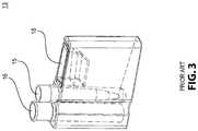
- FIGS. 2-4illustrate a prior art system 10 , whereby a magazine 12 contains a plurality of cartridges 13 , each containing a pipette tip 15 , sample supply container 16 , and a couvette 18 which as illustrated may be an optics cup.
- the sample supply container 16contains a biological sample.
- the sampleis extracted from the container 16 using the pipette tip 15 and, thereafter, subjected to a centrifuge 20 where the particles are concentrated and, thereafter, deposited using the same or another pipette tip 15 , in the couvette 18 for optical analysis.
- FIGS. 2-4While the arrangement in FIGS. 2-4 may be used to identify and quantify microorganisms, a system is need to process microorganisms in a more efficient manner for such identification and quantification.
- FIG. 6illustrates a filter cassette 25 having a sample inlet 27 and a concentrated particle outlet 30 .
- the filter cassette 25includes two separate filters 35 A, 35 B that are used for filtering of the particles as described in the '253 application.
- Multiple ports 40 A, 40 B, 40 C, and 40 Dare provided to supply elution fluid used for the tangential flow of elution fluid over the filters, along with rinse fluid and suction, to achieve the filtering process as described in the '253 application.
- a fluid/particle mixtureis introduced through the sample inlet 27 and deposited upon the upper surface of a first filter 35 A of a filter cassette 25 .
- a rinse fluidis introduced through port 40 B and passed through the filter 35 A to rinse undersize particles from the upper surface of the filter 35 A.
- an elution fluidis introduced though port 40 B to tangentially wipe particles from the upper surface of the filter 35 A.
- These particlesare then deposited upon the upper surface of a second filter 35 B within the cassette 25 .
- a rinse fluidis introduced through port 40 C and passed through the filter 35 B to rinse undersize particles from the upper surface of the filter 35 B.
- an elution fluidis introduced though port 40 C to tangentially wipe particles from the upper surface of the second filter 35 B and the filtering process is ended.
- the filtersmay clog to varying degrees thereby limiting the amount of rinse fluid that may pass through. Because of this, the flow volume through the filters cannot be measured based upon the time of flow, but must be based upon the volume of fluid that has passed through the filters.
- FIG. 6illustrates a slide valve 42 of the cassette 25 with slots 44 , therein, for implementing the multiple steps utilized during the filtering of a sample through the filter cassette 25 .
- An apparatus and methodare needed for processing a biological sample for optical analysis utilizing these filter cassettes. Also, an apparatus and method are needed for properly dosing the rinse fluid over each of the filters.
- a system for processing a biological sample for optical analysishas a plurality of cartridges, wherein each cartridge has a sample supply container for receiving a fluid/particle mixture and each cartridge has a couvette for receiving particles filtered from the fluid/particle mixture.
- the systemhas a cartridge magazine with receivers for holding the plurality of cartridges and a cassette fan having a plurality of slots extending therethrough with each slot adapted to hold a filter cassette, wherein the cassette fan is movable from a first position aligned with select cartridges to a second position away from the cartridges.
- the systemfurther has a cassette clamp positioned over the cassette fan adapted to secure each filter cassette within the fan and to operate the filter cassette.
- a method for processing a biological sample for optical analysiscomprises the step of holding a plurality of cartridges within receivers of a cartridge magazine, wherein each cartridge has a sample supply container for receiving a fluid/particle mixture and each cartridge has a couvette for receiving particles filtered from the fluid/particle mixture.
- a cassette fanhaving a plurality of slots extending therethrough with each slot adapted to hold a filter cassette, the cassette fan is moved to a first position aligned with select cartridges in the magazine.
- a cassette clampis positioned over the cassette fan and secures with the cassette clamp each filter cassette within the fan and operating the filter cassette.
- In yet another embodimentis directed to an apparatus for rinsing undersize particles through a filter element comprising an upper surface of the filter element upon which particles are deposited and a source of rinse fluid for providing rinse fluid through the upper surface of the filter element to displace undersize particles through the filter element; wherein thereafter the used rinse fluid becomes waste fluid.
- a vesselis in fluid connection with the filter element for collecting the waste fluid.
- a measuring devicemeasures the amount of waste fluid in the vessel and upon reaching a predetermined amount of waste fluid, discontinues the rinsing process.
- a source of elution fluidis in fluid communication with the upper surface of the filter element for tangentially wiping particles from the filter.
- FIG. 1is a schematic and shows the prior art steps for processing a biological sample in preparation for optical analysis
- FIG. 2illustrates a prior art system for processing a biological sample for analysis using a centrifuge
- FIG. 3illustrates a prior art cartridge containing a sample supply container and a couvette, therein;
- FIG. 4shows a cross section of the prior art cartridge in FIG. 3 ;
- FIG. 5illustrates a cross section of a cartridge that will be utilized in the present invention
- FIG. 6illustrates a prior art filter cassette used in place of the centrifuge for providing concentrated biological particles in a fluid
- FIG. 7is the prior art filter cassette in FIG. 6 in section view to show a slider valve
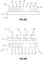
- FIGS. 8A-8Dare sketches illustrating the steps by which a sample is processed in accordance with the subject invention.
- FIG. 8Eshows the progression of cartridge/magazine assembly to position adjacent cartridges under filter cassettes for processing
- FIG. 8Fshows the progression of the cartridge/magazine assembly to position a new subset of cartridges under the filter cassettes
- FIG. 9Ais a perspective view of the processing system in accordance with the subject invention.
- FIG. 9Bis a perspective view of the underside of the cassette fan
- FIG. 10is a perspective view of the processing system with the cassette clamp shown in view
- FIG. 11is a top view of the cassette fan and the cartridge/magazine assembly illustrated in FIG. 9 ;
- FIG. 12is a view of a portion of FIG. 10 with the cartridge shown;
- FIG. 13is the view of FIG. 12 with the cartridge shell removed to show only the couvette and the sample supply container;
- FIG. 14is a view similar to that of FIG. 13 , however, with the cover of the filter cassette removed to show the operating elements;
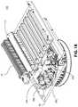
- FIG. 15is a side view along arrows 15 - 15 in FIG. 11 ;
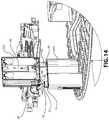
- FIG. 16is a view along arrows 16 - 16 in FIG. 11 ;
- FIG. 17is a view along arrows 17 - 17 in FIG. 11 ;
- FIG. 18is a perspective view of the processing system with the cassette clamp and associated hardware removed;
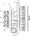
- FIG. 19is a front view of the arrangement in FIG. 18 , but showing the cassette clamp wherein the cassette clamp is in the elevated position for insertion and removal of the filter cassettes;
- FIG. 20is a front view similar to that of FIG. 19 , but with the cassette clamp engaged and securing the filter cassette to the cassette fan;
- FIG. 21is a perspective view of FIG. 19 ;
- FIG. 22is a schematic of single filter element associated with a cassette filter
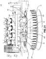
- FIGS. 22A and 23are perspective views of a module containing load cells
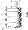
- FIGS. 24 and 25are cross-sectional views of the load cells in FIGS. 22 and 23 ;
- FIG. 26is a schematic of a measurement technique utilizing a capacitive liquid level sensor
- FIG. 27is a front perspective view of one embodiment of an apparatus utilizing a capacitive liquid level sensor to determine the volume of waste fluid;
- FIG. 28is a rear perspective view of the apparatus illustrated in FIG. 27 ;
- FIG. 29is a section view along lines 28 - 28 in FIG. 27 ;
- FIG. 30is a schematic of a liquid measuring technique utilizing an ultrasonic sensor
- FIG. 31is a schematic of a measurement technique utilizing a pressure sensor.
- FIG. 32is a schematic of a measurement technique using a radar sensor.
- FIG. 2illustrates a system for concentrating particles using a centrifuge and, thereafter, subjecting the particles to optical analysis
- the subject inventionis directed to the manner by which particles are concentrated utilizing the prior art filter cassette 25 illustrated in FIGS. 6-7 .
- FIG. 5shows a cross-sectional view of a cartridge 14 that may be used in the system of the present invention.
- the cartridge 14is similar to the cartridge 13 shown in FIGS. 3-4 .
- the cartridge 14 in FIG. 5includes only a sample supply container 16 and a couvette 18 .
- the design of the filter cassette 25allows multiple filter cassettes 25 to be operated simultaneously using multiple cartridges 14 mounted within a magazine 12 .
- FIGS. 8A-8Dare sketches illustrating the process by which multiple cartridges 14 A- 14 H mounted within the magazine 12 are processed.
- the cartridge 14 /magazine 12 togetherwill be referred to as the cartridge/magazine assembly 17 .
- the cartridges 14are identical to one another, to better define the positional relationship of each cartridge 14 in the foregoing processes, the cartridges herein will be referred to as 14 A- 14 Q with the understanding that the magazine 12 is not limited to sixteen cartridges.
- a single cartridge magazine 12may, for example, hold forty cartridges 14 .
- a cassette fan 50is positioned proximate to the cartridge/magazine assembly 17 . Slots 52 , 54 , 56 , 58 extend through the fan 50 .
- the filter cassettes 25 A- 25 Dare mounted within the slots 52 , 54 , 56 , 58 of the fan 50 as in FIG. 8C .
- the fan 50is positioned over the cartridge/magazine assembly 17 such that slots 52 , 54 , 56 , 58 extending through the fan 50 are aligned with cartridges 14 B, 14 D, 14 F, 14 H.
- a cassette clamp 60is placed over the filter cassettes 25 A- 25 D at which time each filter cassette 25 A- 25 D extracts particles suspended in fluid from the sample supply container within the respective cartridges 14 B, 14 D, 14 F, 14 H. The particles suspended in fluid are then filtered and concentrated using the filter cassettes 25 A- 25 D. Once the particles are concentrated, then the particles are deposited into the couvette 18 ( FIG. 4 ) in each of the cartridges 14 B, 14 D, 14 F, 14 H for further optical analysis.
- the filter cassettes 25 A- 25 Dare associated with cartridges 14 B, 14 D, 14 F, 14 H. Each of these cartridges is spaced apart from one another by one cartridge. There is hardware between each of the filter cassettes, for example, 25 B, 25 D, which may limit the spacing between adjacent filter cassettes. While FIGS. 8A-8D show one filter cassette 14 A, 14 C, 14 E, 14 G between each filter cassette 25 A- 25 D, another embodiment of the invention has two filter cassettes between each filter cartridge. In particular, FIG. 19 illustrates one such embodiment.
- the cassette fan 50 and a carousel 62may be indexed to remove used filter cassettes 25 A- 25 D and to align newly mounted filter cassettes 25 E- 25 H within the cassette fan 50 with different cartridges in the magazine 12 .
- the cartridge/magazine assembly 17is indexed, as shown by arrows A 1 , to the left to align a set of adjacent cartridges 14 C, 14 E, 14 G, 14 I with the new filter cassettes 25 E- 25 H for processing as described.
- the assembly 17cannot be indexed in direction A 1 by only one cartridge since all but one of the adjacent cartridges have already been processed. Therefore, as illustrated in FIG.
- an entire new subset of cartridges 14 J- 14 Pis indexed such that cassettes 14 J- 14 P are aligned and processed with yet another set of new filter cassettes 25 I- 25 L. Thereafter, the assembly 17 is indexed to align cassettes 14 K, 14 M, 14 O, and 14 Q for processing. This sequence may be repeated until the entire inventory of cassettes in the magazine 12 is processed.
- FIG. 9Ais a perspective view of the entire system including the cartridge/magazine assembly 17 , the cartridges 14 A- 14 H, the cassette fan 50 , filter cassettes 25 A- 25 D, and the cassette clamp 60 .
- FIG. 9Billustrates the underside 61 of the cassette clamp 60 .
- the clamphas a set of connections 64 A- 64 D each of which engages the ports 40 A- 40 D of each of the filter cassettes 25 A- 25 D.
- the cassette clamp 60through the sets of connections 64 A- 64 D provides elution fluid, rinse fluid and vacuum to the appropriate ports 40 A- 40 D ( FIG. 5 ) of the filter cassettes 25 A- 25 D, while the motors 63 A- 63 D situated on the cassette clamp 60 position the slide valve 42 ( FIG. 6 ) of each filter cassette 25 A- 25 D in the appropriate position so that the channels 44 ( FIG. 6 ) establish the fluid path to achieve different stages of filtering within the filter cassettes 25 A- 25 D.
- FIG. 10illustrates a perspective view of one embodiment of the system whereby the cartridge/magazine assembly 17 is secured to the carousel 62 .
- a cassette fan 50is positioned over the carousel 62 such that the filter cassette 25 D, secured within a slot 58 of the cassette fan 50 , is positioned directly over the cartridge 14 D secured within the magazine 12 .
- FIG. 11illustrates a top view of the arrangement of FIG. 10 whereby, the cassette fan 50 includes four slots 52 , 54 , 56 , 58 to accommodate four filter cassettes (not shown).
- FIG. 12shows a cartridge 14 H positioned on the magazine 12 with the cassette fan 50 positioned above the cartridge 14 H.
- FIG. 13is a perspective view similar to FIG. 12 , wherein the cassette fan 50 is positioned above the cartridge/magazine assembly 17 . However, for illustrative purposes, the shell 13 A of the cartridge 14 H ( FIG. 12 ) has been removed to show only the sample supply container 16 and the couvette 18 .
- the filter cassette 25 Dhas an inlet tube 28 , wherein once the filter cassette 25 D is properly positioned over the assembly 17 with the sample supply container 16 and the couvette 18 , the biological sample with particles may be extracted from the sample supply container 16 and processed through the filter cassette 25 D where it is discharged through the particle outlet 30 .
- the particle outlet 30 of the filter cassette 25 Dis positioned directly above the couvette 18 such that, after filtering, the concentrated particles suspended in fluid may be directly deposited from the filter cassette 25 D through the particle outlet 30 into the couvette 18 .
- the filter cassette 25 D as illustrated in FIG. 14has the cover removed to expose the sample inlet 27 , which is in the form of the inlet tube 28 .
- the inlet tube 28is advanced by pinch rollers 65 , 66 operated by a motor driven gear mechanism 68 .
- filter cassette 25 Dmay be proximate to the cartridge 14 H, and the inlet tube 28 may be advanced into the sample supply container 16 to extract the biological sample for filtering. Thereafter, the tube 28 may be retracted from the sample supply container 16 .
- the filtering processthen proceeds using the filter cassette 25 D.
- FIG. 15is a side view along arrows 15 - 15 in FIG. 11
- FIG. 16is a side view along arrows 16 - 16 in FIG. 11
- FIG. 17is a side view along arrows 17 - 17 in FIG. 11 .
- FIG. 18is similar to FIG. 9A but with the cassette clamp 60 removed to illustrate details of the cassette fan 50 .
- FIGS. 19 and 20show the system 110 with the cassette clamp 60 in the retracted position ( FIG. 19 ) above the filter cassettes 25 A- 25 D and lowered ( FIG. 20 ) to engage the filter cassettes 25 A- 25 D.
- the cassette clamp 60not only secures each cassette 25 A- 25 D, but the clamp 60 is also utilized to operate each filter cassette 25 A- 25 D.
- FIG. 21shows a perspective view of the system 110 with the cassette clamp 60 retracted from the filter cassettes 25 A- 25 D ( FIG. 20 ). While the cassette fan 50 , as shown, supports four filter cassettes 25 A- 25 D, it may be modified to accommodate any number of filter cassettes.
- FIG. 18shows the processing system 110 with the fan 50 and the associated hardware removed for a clear view of the filter cassette supply magazine 75 and the filter cassette depository magazine 77 .
- the fan 50rotates about a center axis such that each slot 52 , 54 , 56 , 58 of the fan 50 is rotated into a position parallel to the cassette 25 in the supply magazine 75 .
- a mechanical arm(not shown) picks a filter cassette 25 from the supply magazine 75 and places it in a vacant slot of the fan 50 . The fan 50 is then indexed so the next vacant slot is parallel to the cassette 25 and that cassette is picked and placed into the slot.
- the fan 50is then rotated and indexed so that the newly mounted filter cassettes 25 are aligned with respective cartridges 14 .
- the clamp 60is vertically displaced to provide clearance.
- the clamp 60is lowered such that the ports 40 A, 40 B, 40 C, 40 D ( FIG. 5 ) are attached to corresponding connectors in the clamp 60 for processing.
- the clamp 60is again moved to the raised position ( FIG. 21 ), the fan 50 indexed, and the used filter cassettes 25 are removed from the fan 50 and placed within the filter cassette depository magazine 77 ( FIG. 18 ).
- the fan 50is again populated with new filter cassettes and indexed to align with other cartridges for processing.
- each cartridge 14 /filter cassette 25 pairoperates independently from the other cartridge 14 /filter cassette 25 pairs.
- a system 110 for processing a biological sample for optical analysishas a plurality of cartridges 14 , wherein each cartridge 14 has a sample supply container 16 for receiving a fluid/particle mixture and each cartridge has a couvette 18 for receiving particles filtered from the fluid/particle mixture.
- a cartridge magazine 17has receivers for holding the plurality of cartridges 14 .
- a cassette fan 50has a plurality of slots 52 , 54 , 56 , 58 extending therethrough with each slot adapted to hold a filter cassette 25 .
- the cassette fan 50is movable from a first position aligned with select cartridges 14 within the magazine 12 to a second position away from the cartridges 14 .
- a cassette clamp 60 positioned over the cassette fan 50is adapted to secure each filter cassette 14 A- 14 D within the fan 50 and to operate the filter cassettes 14 A- 14 D.
- a method for processing a biological sample for optical analysismay comprise the steps holding a plurality of cartridges 14 within receivers of a cartridge magazine 12 , wherein each cartridge 14 has a sample supply container 16 for receiving a fluid/particle mixture and each cartridge 14 has a couvette 18 for receiving particles filtered from the fluid/particle mixture.
- a cassette fan 50has a plurality of slots 52 , 54 , 56 , 58 extending therethrough with each slot adapted to hold a filter cassette 25 A- 25 D. The fan 50 moves the cassette fan 50 to a first position aligned with select cartridges in the magazine 12 .
- a cassette clamp 60is positioned over the cassette fan 50 and secures each filter cassette 25 A- 25 D within the fan 50 and operates each filter cassette 25 A- 25 D.
- the filtering processis as follows. Inside each filter cassette, illustrated schematically as 300 , is a top element 315 , a bottom element 320 and a filter element 325 therebetween. A fluid particle mixture is deposited upon an upper surface 345 of the filter element 325 . Thereafter, a rinse fluid from inlet 330 is passed through the upper surface 345 of the filter element 325 to remove under-sized particle from the filter surface 345 . After the rinse fluid is passed through the filter element 325 , it becomes waste fluid and is deposited into a collector. The upper surface 345 of the filter element 325 is then tangentially rinsed with an elution fluid to displace the deposited particles for further processing.
- the rate of flow of rinse fluid through each filtervaries depending upon the amount of clogging produced by the particles in each filter. To provide a uniform filtering process at each filter, it is necessary to achieve a relatively uniform volume of flow past each filter. Because of the varying rate of flow through each filter, this task cannot be achieved by activating the flow for a fixed amount of time for each filter.
- the inventorhas discovered that it is possible to measure the volume of flow past each filter using different non-time dependent techniques.
- the volume of flowis measured after the rinse fluid has passed through the filter based upon the weight or the volume of the fluid.
- the waste fluidis accumulated in a vessel placed over a load cell and the weight of the accumulated fluid is measured until a predetermined weight is reached. At that time, the flow of the rinse fluid is discontinued for that filter. Then tangential wiping with the elution fluid is started and thereafter the filtering procedure associated with that particular cartridge 14 and filter cassette 25 pair is stopped.
- FIGS. 22 and 23illustrate perspective views of a module 80 having four vessels 82 A- 82 D with load cells 84 A- 84 D. Each vessel 82 A- 82 D is associated with a filter cassette such that when a new filter cassette 25 is used to process the sample from the sample supply container 16 of a cartridge 14 , the quantity of waste fluid passing through the filter cassette is measured by the load cell until a predetermined threshold has been reached. At that time, the rinsing stops and the waste fluid is discharged from the load cell.
- FIGS. 24 and 25show cross-section views of the vessels 82 A- 82 D.
- FIG. 24shows details of a mass meter 80 having four vessels 82 A, 82 B, 82 C and 82 D each associated with a separate filter cassette.
- vessel 82 Arests upon a load cell 84 , such as a piezoelectric transducer.
- the weight of the fluid within the vessel 82 Amay be determined using this load cell 84 .
- an accurate estimation of the volume of fluid travelling through each filteris provided by the weight of the fluid within the vessel 82 A associated with that filter without the need to use direct volume measuring devices.
- Such direct volume measuring devicesare not ideal for variable flow, such as that through a filter which may be partially clogged, and are relatively expensive.
- FIG. 1illustrates a container 200 with fluid F therein.
- a capacitive level sensorwhich is known to those skilled in the art, includes two electrodes 205 , 210 electrically insulated from each other. As the liquid in the container 200 rises, the dielectric between the two electrodes changes from essentially air to liquid and, as a result, the capacitance changes. By measuring this change of capacitance, the liquid level can be determined.
- FIGS. 27-29The hardware for achieving this task is illustrated in FIGS. 27-29 wherein four separate containers 200 A- 200 D are illustrated. QAs shown in FIG. 29 , external sensors 213 A- 213 D, each made up of two spaced apart electrically insulated electrodes (not shown) are associated with containers 200 A- 200 D to detect the level of waste fluid in each container 200 A- 200 D.
- FIG. 30illustrates a use of an ultra sound sensor 215 which placed upon the side of the container senses when the fluid F reaches a predetermined height at which time the process may be terminated.
- sensorsare well known to one skilled in the art. It is also possible to position the sensor 215 at the bottom or at the top of the container such that the sound waves of the sensor will travel upward or downward to the boundary of the fluid. In this fashion, the height of fluid in the container may be determined.
- FIG. 31illustrates an arrangement whereby the pressure of the Fluid F within the container 200 may be measured with the knowledge that as the liquid level increases, the water pressure at a predetermined submerged point increases.
- a tube 220penetrates the side of the container 200 such that at Liquid L the pressure may be measured by a pressure sensor P. In this fashion, it is possible that at a predetermined pressure, the rinsing process will terminate. It is also possible to introduce a membrane between the sensor and the vessel to sense pressure placed on the membrane by the fluid.
- FIG. 4illustrates yet another technique for measuring the fluid F.
- a radar sensor Rmay be placed at the top of the container 200 and by measuring the distance between the radar sensor R and the top of the fluid F, the fluid level may be determined such that, once again, at a predetermined level, the rinsing process may be terminated.
Landscapes
- Chemical & Material Sciences (AREA)
- Health & Medical Sciences (AREA)
- Analytical Chemistry (AREA)
- General Health & Medical Sciences (AREA)
- Chemical Kinetics & Catalysis (AREA)
- Physics & Mathematics (AREA)
- Life Sciences & Earth Sciences (AREA)
- Biochemistry (AREA)
- General Physics & Mathematics (AREA)
- Immunology (AREA)
- Pathology (AREA)
- Clinical Laboratory Science (AREA)
- Hematology (AREA)
- Sampling And Sample Adjustment (AREA)
- Automatic Analysis And Handling Materials Therefor (AREA)
Abstract
Description
- a) depositing particles upon an upper surface of the filter element;
- b) providing rinse fluid through the upper surface of the filter element to displace undersize particles through the filter element; wherein thereafter the used rinse fluid becomes waste fluid;
- c) collecting the waste fluid in a vessel;
- d) measuring the amount of waste fluid in the vessel and upon reaching a predetermined amount of waste fluid, discontinuing the rinsing; and
- e) if the amount of waste fluid in the vessel is less than the predetermined amount of waste fluid, then repeat steps b)-d).
Claims (20)
Priority Applications (1)
| Application Number | Priority Date | Filing Date | Title |
|---|---|---|---|
| US16/052,969US10739237B2 (en) | 2017-08-02 | 2018-08-02 | Processor filter arrangement that includes method and apparatus to remove waste fluid through a filter |
Applications Claiming Priority (3)
| Application Number | Priority Date | Filing Date | Title |
|---|---|---|---|
| US201762540357P | 2017-08-02 | 2017-08-02 | |
| US201762547359P | 2017-08-18 | 2017-08-18 | |
| US16/052,969US10739237B2 (en) | 2017-08-02 | 2018-08-02 | Processor filter arrangement that includes method and apparatus to remove waste fluid through a filter |
Publications (2)
| Publication Number | Publication Date |
|---|---|
| US20190041307A1 US20190041307A1 (en) | 2019-02-07 |
| US10739237B2true US10739237B2 (en) | 2020-08-11 |
Family
ID=65229918
Family Applications (1)
| Application Number | Title | Priority Date | Filing Date |
|---|---|---|---|
| US16/052,969Expired - Fee RelatedUS10739237B2 (en) | 2017-08-02 | 2018-08-02 | Processor filter arrangement that includes method and apparatus to remove waste fluid through a filter |
Country Status (7)
| Country | Link |
|---|---|
| US (1) | US10739237B2 (en) |
| EP (1) | EP3662246A4 (en) |
| JP (1) | JP7209374B2 (en) |
| CN (1) | CN111065904A (en) |
| CA (1) | CA3070832A1 (en) |
| IL (1) | IL272368A (en) |
| WO (1) | WO2019026026A1 (en) |
Families Citing this family (5)
| Publication number | Priority date | Publication date | Assignee | Title |
|---|---|---|---|---|
| GB2592082B (en)* | 2019-07-31 | 2023-11-01 | Agency Defense Dev | Small apparatus for identifying biological particles |
| US12414839B2 (en)* | 2021-09-28 | 2025-09-16 | Andrew Peter Davis | Tonometer disinfection systems, methods, and devices |
| CN114602322B (en)* | 2022-02-16 | 2023-06-27 | 中国科学院水生生物研究所 | A cartridge-type filter replacement system for environmental DNA sampling |
| CN114602323B (en)* | 2022-02-18 | 2023-05-09 | 中国科学院水生生物研究所 | Method and system for clamping filter membrane replacement for environmental DNA sampling |
| CN114602324B (en)* | 2022-02-18 | 2023-06-27 | 中国科学院水生生物研究所 | A clip-on membrane replacement system for environmental DNA sampling |
Citations (50)
| Publication number | Priority date | Publication date | Assignee | Title |
|---|---|---|---|---|
| US3754868A (en) | 1970-07-06 | 1973-08-28 | Aerojet General Co | Device for preparation of sample for biological agent detector |
| US4096062A (en) | 1975-10-06 | 1978-06-20 | Paraisten Kalkki Oy - Pargas Kalk Ab | Method and device for separation of suspended material from a fluid flow |
| US4427415A (en) | 1979-01-05 | 1984-01-24 | Cleveland Patrick H | Manifold vacuum biochemical test method and device |
| US5180606A (en) | 1989-05-09 | 1993-01-19 | Wescor, Inc. | Apparatus for applying a controlled amount of reagent to a microscope slide or the like |
| US5375477A (en) | 1993-01-04 | 1994-12-27 | S.P. Industries, Limited Partnership | Water impurity extraction device and method |
| US5380437A (en) | 1993-02-02 | 1995-01-10 | Biomedical Research And Development Laboratories, Inc. | Multifunctional filtration apparatus |
| US5603900A (en) | 1995-05-19 | 1997-02-18 | Millipore Investment Holdings Limited | Vacuum filter device |
| US5683658A (en) | 1995-07-14 | 1997-11-04 | Avl Medical Instruments Ag | Reagent bottle |
| US5947689A (en) | 1997-05-07 | 1999-09-07 | Scilog, Inc. | Automated, quantitative, system for filtration of liquids having a pump controller |
| US5976824A (en) | 1993-11-24 | 1999-11-02 | Abbott Laboratories | Method and apparatus for collecting a cell sample from a liquid specimen |
| US6338802B1 (en) | 1998-10-29 | 2002-01-15 | Pe Corporation (Ny) | Multi-well microfiltration apparatus |
| EP1179585A2 (en) | 1997-12-24 | 2002-02-13 | Cepheid | Integrated fluid manipulation cartridge |
| US20020030015A1 (en) | 1998-06-03 | 2002-03-14 | Accurate Polymers | Static separation method using non-porous cellulose beads |
| US20020045243A1 (en) | 2000-09-15 | 2002-04-18 | Laska Ronald C. | Fluid cartridge and method |
| US20040026322A1 (en) | 2002-08-09 | 2004-02-12 | Sartorius Ag | Process and apparatus for adsorptive separation of substances |
| US6692702B1 (en) | 2000-07-07 | 2004-02-17 | Coulter International Corp. | Apparatus for biological sample preparation and analysis |
| US20050173315A1 (en) | 2002-06-19 | 2005-08-11 | Northwest Biotherapeutics, Inc. | Tangential flow filtration devices and methods for leukocyte enrichment |
| US6949355B2 (en) | 2001-10-11 | 2005-09-27 | Aviva Biosciences | Methods, compositions, and automated systems for separating rare cells from fluid samples |
| US7100461B2 (en) | 2002-02-27 | 2006-09-05 | Microbial-Vac Systems, Inc. | Portable contaminant sampling system |
| US7240572B2 (en) | 2004-02-18 | 2007-07-10 | Millipore Corporation | Vacuum assisted affinity chromatography device and method |
| US20080023381A1 (en) | 2003-11-14 | 2008-01-31 | Nicholas Jackson | Fluid Filtration System and Method of Filtering Fluid |
| US7374724B2 (en) | 2001-05-29 | 2008-05-20 | Tecan Trading Ag | Device for processing samples, use of the device, and method for producing the device |
| US20080237142A1 (en) | 2007-04-02 | 2008-10-02 | Battelle Energy Alliance, Llc | Systems and methods for concentrating substances in fluid samples |
| WO2008151093A1 (en) | 2007-05-30 | 2008-12-11 | Alburtylab, Inc. | Liquid to liquid biological particle concentrator |
| US7510654B2 (en) | 2005-12-29 | 2009-03-31 | Spf Innovations, Llc | Method and apparatus for the filtration of biological samples |
| US20090126514A1 (en) | 2007-09-05 | 2009-05-21 | Eric Gregory Burroughs | Devices for collection and preparation of biological agents |
| US20090217777A1 (en) | 2008-03-03 | 2009-09-03 | Hanson William P | Analyte screening and detection systems and methods |
| US20090280565A1 (en) | 2005-12-22 | 2009-11-12 | Corporation De L'ecole Polytechique Montr'eal | High-rate perfusion bioreactor |
| US20090277833A1 (en) | 2008-05-06 | 2009-11-12 | Spf Innovations, Llc | Tangential flow filtration system |
| US20100051527A1 (en) | 2007-03-09 | 2010-03-04 | Mikkel Vestergaard Frandsen | Microporous filter with an antimicrobial source |
| US20100068706A1 (en) | 1998-12-24 | 2010-03-18 | Cepheid | Method for separating an analyte from a sample |
| US20100139415A1 (en)* | 2005-09-22 | 2010-06-10 | Endress + Hauser Flowtec Ag | Method for Monitoring an Ultrasound Flowmeter System and/or Process |
| US20100313685A1 (en) | 2009-06-12 | 2010-12-16 | Innovaprep Llc | Surface Sampler for Biological Particles |
| US20110061474A1 (en) | 2009-09-17 | 2011-03-17 | Innovaprep Llc | Liquid to Liquid Biological Particle Concentrator with Disposable Fluid Path |
| US20110108483A1 (en) | 2008-04-03 | 2011-05-12 | Povl Kaas | Filter unit with filter bank |
| US20110197685A1 (en) | 2010-02-16 | 2011-08-18 | Innovaprep Llc | Portable Concentrator |
| US8007743B2 (en) | 2003-06-24 | 2011-08-30 | Millipore Corporation | Multifunctional vacuum manifold |
| US8033187B2 (en) | 2004-01-14 | 2011-10-11 | Max-Planck-Gessellschaft Zur Forderung der Wissenschafter E.V. | Device and method for taking samples |
| US20120156716A1 (en) | 2010-12-17 | 2012-06-21 | Biomerieux, Inc. | Methods For The Isolation, Accumulation, Characterization And/Or Identification Of Microorganisms Using A Filtration And Sample Transfer Device |
| US20130045532A1 (en) | 2011-07-22 | 2013-02-21 | Boimerieux, Inc. | Methods and kits for isolating microorganisms from culture |
| US20130059326A1 (en) | 2010-01-14 | 2013-03-07 | Emd Millipore Corporation | Membrane Transfer Method And Tool |
| US20130086980A1 (en) | 2010-04-20 | 2013-04-11 | Eltek S.P.A. | Microfluidic devices and/or equipment for microfluidic devices |
| EP2645078A1 (en) | 2012-03-29 | 2013-10-02 | Roche Diagniostics GmbH | Micro flow filtration system and integrated microfluidic device |
| US8584536B2 (en) | 2009-09-21 | 2013-11-19 | Innovaprep Llc | Devices, systems and methods for elution of particles from flat filters |
| WO2013173524A2 (en) | 2012-05-15 | 2013-11-21 | Wellstat Diagnostics, Llc | Clinical diagnostic system including instrument and cartridge |
| US8804114B2 (en) | 2010-11-03 | 2014-08-12 | Pocared Diagnostics Ltd. | Optical cup |
| WO2014123896A1 (en) | 2013-02-05 | 2014-08-14 | Pocared Diagnostics Ltd. | Filter arrangement and method for using the same |
| US20150151253A1 (en)* | 2013-12-04 | 2015-06-04 | Pocared Diagnostics Ltd. | Method and Apparatus for Processing and Analyzing filtered Particles |
| GB2531616A (en) | 2015-02-02 | 2016-04-27 | Atlas Genetics Ltd | Instrument for performing a diagnostic test on a fluidic cartridge |
| US9506866B2 (en) | 2008-02-05 | 2016-11-29 | Pocared Diagnostics Ltd. | System for conducting the identification of bacteria in biological samples |
Family Cites Families (18)
| Publication number | Priority date | Publication date | Assignee | Title |
|---|---|---|---|---|
| AU749820B2 (en) | 1997-11-04 | 2002-07-04 | La Mina Ltd | Method and apparatus for mixing and separating particulate matter from a liquid specimen |
| US20060104861A1 (en)* | 2004-09-30 | 2006-05-18 | Windus-Smith Bryan K | Test sensor transport mechanisms and methods |
| JP4478588B2 (en) | 2005-01-31 | 2010-06-09 | 富士フイルム株式会社 | Specific substance recovery apparatus and nucleic acid extraction apparatus using the same |
| US20060228265A1 (en)* | 2005-04-07 | 2006-10-12 | Peng Sean X | Particulate separation filters and methods |
| US7759112B2 (en)* | 2007-10-31 | 2010-07-20 | Akonni Biosystems, Inc. | Apparatus, system, and method for purifying nucleic acids |
| US8647574B2 (en)* | 2007-11-20 | 2014-02-11 | 3M Innovative Properties Company | Sample preparation container and method |
| JP5097657B2 (en) | 2008-09-17 | 2012-12-12 | アークレイ株式会社 | Analysis method |
| US10288632B2 (en) | 2009-09-21 | 2019-05-14 | Pocared Diagnostics Ltd. | System for conducting the identification of bacteria in biological samples |
| JP5503360B2 (en) | 2010-01-15 | 2014-05-28 | シスメックス株式会社 | Sample preparation equipment |
| EP2380611B1 (en) | 2010-04-20 | 2013-05-29 | Sorin Group Italia S.r.l. | Blood reservoir with level sensor |
| SE534913C2 (en)* | 2010-06-16 | 2012-02-14 | Rioks Patenter Ab | Disc filter |
| US20140004505A1 (en)* | 2011-03-10 | 2014-01-02 | Biodetection Instruments, Llc | Cartridge based system and method for detecting an analyte in a sample |
| GB201111080D0 (en)* | 2011-06-29 | 2011-08-10 | Ge Healthcare Uk Ltd | Syringeless filter device compressor |
| WO2013028980A1 (en)* | 2011-08-24 | 2013-02-28 | Abbott Point Of Care, Inc. | Biologic fluid sample analysis cartridge |
| CN103959037A (en)* | 2011-10-25 | 2014-07-30 | 皇家飞利浦有限公司 | Filtering particles from blood or other media |
| KR101352900B1 (en)* | 2012-07-31 | 2014-01-23 | 주식회사 아이센스 | Biochemical assay cartridge with improved operability |
| EP2952258A1 (en)* | 2014-06-06 | 2015-12-09 | Roche Diagnostics GmbH | Rotatable cartridge for analyzing a biological sample |
| EP3048163B1 (en)* | 2014-11-20 | 2020-04-08 | UNIST (Ulsan National Institute of Science and Technology) | Particle filtering device and particle filtering method |
- 2018
- 2018-08-02JPJP2020505388Apatent/JP7209374B2/enactiveActive
- 2018-08-02CACA3070832Apatent/CA3070832A1/enactivePending
- 2018-08-02WOPCT/IB2018/055827patent/WO2019026026A1/ennot_activeCeased
- 2018-08-02USUS16/052,969patent/US10739237B2/ennot_activeExpired - Fee Related
- 2018-08-02EPEP18841189.6Apatent/EP3662246A4/ennot_activeWithdrawn
- 2018-08-02CNCN201880057261.3Apatent/CN111065904A/enactivePending
- 2020
- 2020-01-30ILIL272368Apatent/IL272368A/enunknown
Patent Citations (62)
| Publication number | Priority date | Publication date | Assignee | Title |
|---|---|---|---|---|
| US3754868A (en) | 1970-07-06 | 1973-08-28 | Aerojet General Co | Device for preparation of sample for biological agent detector |
| US4096062A (en) | 1975-10-06 | 1978-06-20 | Paraisten Kalkki Oy - Pargas Kalk Ab | Method and device for separation of suspended material from a fluid flow |
| US4427415A (en) | 1979-01-05 | 1984-01-24 | Cleveland Patrick H | Manifold vacuum biochemical test method and device |
| US5180606A (en) | 1989-05-09 | 1993-01-19 | Wescor, Inc. | Apparatus for applying a controlled amount of reagent to a microscope slide or the like |
| US5375477A (en) | 1993-01-04 | 1994-12-27 | S.P. Industries, Limited Partnership | Water impurity extraction device and method |
| US5380437A (en) | 1993-02-02 | 1995-01-10 | Biomedical Research And Development Laboratories, Inc. | Multifunctional filtration apparatus |
| US5976824A (en) | 1993-11-24 | 1999-11-02 | Abbott Laboratories | Method and apparatus for collecting a cell sample from a liquid specimen |
| US5603900A (en) | 1995-05-19 | 1997-02-18 | Millipore Investment Holdings Limited | Vacuum filter device |
| US5683658A (en) | 1995-07-14 | 1997-11-04 | Avl Medical Instruments Ag | Reagent bottle |
| US5947689A (en) | 1997-05-07 | 1999-09-07 | Scilog, Inc. | Automated, quantitative, system for filtration of liquids having a pump controller |
| US20020042125A1 (en) | 1997-08-13 | 2002-04-11 | Cepheid | Method for separating analyte from a sample |
| EP1179585A2 (en) | 1997-12-24 | 2002-02-13 | Cepheid | Integrated fluid manipulation cartridge |
| US20020030015A1 (en) | 1998-06-03 | 2002-03-14 | Accurate Polymers | Static separation method using non-porous cellulose beads |
| US6338802B1 (en) | 1998-10-29 | 2002-01-15 | Pe Corporation (Ny) | Multi-well microfiltration apparatus |
| US20100068706A1 (en) | 1998-12-24 | 2010-03-18 | Cepheid | Method for separating an analyte from a sample |
| US6692702B1 (en) | 2000-07-07 | 2004-02-17 | Coulter International Corp. | Apparatus for biological sample preparation and analysis |
| US20040132198A1 (en) | 2000-07-07 | 2004-07-08 | Coulter International Corp. | Apparatus and method for biological sample preparation and analysis |
| US20040132208A1 (en) | 2000-07-07 | 2004-07-08 | Coulter International Corp. | Apparatus and method for sample purification analysis |
| US20020045243A1 (en) | 2000-09-15 | 2002-04-18 | Laska Ronald C. | Fluid cartridge and method |
| US7374724B2 (en) | 2001-05-29 | 2008-05-20 | Tecan Trading Ag | Device for processing samples, use of the device, and method for producing the device |
| US6949355B2 (en) | 2001-10-11 | 2005-09-27 | Aviva Biosciences | Methods, compositions, and automated systems for separating rare cells from fluid samples |
| US7100461B2 (en) | 2002-02-27 | 2006-09-05 | Microbial-Vac Systems, Inc. | Portable contaminant sampling system |
| US20050173315A1 (en) | 2002-06-19 | 2005-08-11 | Northwest Biotherapeutics, Inc. | Tangential flow filtration devices and methods for leukocyte enrichment |
| US7695627B2 (en) | 2002-06-19 | 2010-04-13 | Northwest Biotherapeutics, Inc. | Tangential flow filtration devices and methods for leukocyte enrichment |
| US20040026322A1 (en) | 2002-08-09 | 2004-02-12 | Sartorius Ag | Process and apparatus for adsorptive separation of substances |
| US8007743B2 (en) | 2003-06-24 | 2011-08-30 | Millipore Corporation | Multifunctional vacuum manifold |
| US20080023381A1 (en) | 2003-11-14 | 2008-01-31 | Nicholas Jackson | Fluid Filtration System and Method of Filtering Fluid |
| US8033187B2 (en) | 2004-01-14 | 2011-10-11 | Max-Planck-Gessellschaft Zur Forderung der Wissenschafter E.V. | Device and method for taking samples |
| US7240572B2 (en) | 2004-02-18 | 2007-07-10 | Millipore Corporation | Vacuum assisted affinity chromatography device and method |
| US20100139415A1 (en)* | 2005-09-22 | 2010-06-10 | Endress + Hauser Flowtec Ag | Method for Monitoring an Ultrasound Flowmeter System and/or Process |
| US20090280565A1 (en) | 2005-12-22 | 2009-11-12 | Corporation De L'ecole Polytechique Montr'eal | High-rate perfusion bioreactor |
| US7682511B2 (en) | 2005-12-29 | 2010-03-23 | Spf Innovations, Llc | Method and apparatus for the filtration of biological solutions |
| US7510654B2 (en) | 2005-12-29 | 2009-03-31 | Spf Innovations, Llc | Method and apparatus for the filtration of biological samples |
| US20100051527A1 (en) | 2007-03-09 | 2010-03-04 | Mikkel Vestergaard Frandsen | Microporous filter with an antimicrobial source |
| US20080237142A1 (en) | 2007-04-02 | 2008-10-02 | Battelle Energy Alliance, Llc | Systems and methods for concentrating substances in fluid samples |
| US8110112B2 (en) | 2007-05-30 | 2012-02-07 | Innova Prep LLC | Liquid to liquid biological particle concentrator |
| WO2008151093A1 (en) | 2007-05-30 | 2008-12-11 | Alburtylab, Inc. | Liquid to liquid biological particle concentrator |
| US20090101575A1 (en) | 2007-05-30 | 2009-04-23 | Alburty David S | Liquid To Liquid Biological Particle Concentrator |
| US20090126514A1 (en) | 2007-09-05 | 2009-05-21 | Eric Gregory Burroughs | Devices for collection and preparation of biological agents |
| US9506866B2 (en) | 2008-02-05 | 2016-11-29 | Pocared Diagnostics Ltd. | System for conducting the identification of bacteria in biological samples |
| US20090217777A1 (en) | 2008-03-03 | 2009-09-03 | Hanson William P | Analyte screening and detection systems and methods |
| US20110108483A1 (en) | 2008-04-03 | 2011-05-12 | Povl Kaas | Filter unit with filter bank |
| US20090277833A1 (en) | 2008-05-06 | 2009-11-12 | Spf Innovations, Llc | Tangential flow filtration system |
| US20100313686A1 (en) | 2009-06-12 | 2010-12-16 | Innovaprep Llc | Surface Sampler for Bioterrorism Particle Detection |
| US20100313685A1 (en) | 2009-06-12 | 2010-12-16 | Innovaprep Llc | Surface Sampler for Biological Particles |
| US8584535B2 (en) | 2009-09-17 | 2013-11-19 | Innova Prep LLC | Liquid to liquid biological particle concentrator with disposable fluid path |
| US20110061474A1 (en) | 2009-09-17 | 2011-03-17 | Innovaprep Llc | Liquid to Liquid Biological Particle Concentrator with Disposable Fluid Path |
| US8584536B2 (en) | 2009-09-21 | 2013-11-19 | Innovaprep Llc | Devices, systems and methods for elution of particles from flat filters |
| US20130059326A1 (en) | 2010-01-14 | 2013-03-07 | Emd Millipore Corporation | Membrane Transfer Method And Tool |
| US20110197685A1 (en) | 2010-02-16 | 2011-08-18 | Innovaprep Llc | Portable Concentrator |
| US20130086980A1 (en) | 2010-04-20 | 2013-04-11 | Eltek S.P.A. | Microfluidic devices and/or equipment for microfluidic devices |
| US8804114B2 (en) | 2010-11-03 | 2014-08-12 | Pocared Diagnostics Ltd. | Optical cup |
| US20120156716A1 (en) | 2010-12-17 | 2012-06-21 | Biomerieux, Inc. | Methods For The Isolation, Accumulation, Characterization And/Or Identification Of Microorganisms Using A Filtration And Sample Transfer Device |
| US20130045532A1 (en) | 2011-07-22 | 2013-02-21 | Boimerieux, Inc. | Methods and kits for isolating microorganisms from culture |
| EP2645078A1 (en) | 2012-03-29 | 2013-10-02 | Roche Diagniostics GmbH | Micro flow filtration system and integrated microfluidic device |
| US20150041375A1 (en) | 2012-03-29 | 2015-02-12 | Hoffmann-La Roche Inc. | Micro flow filtration system and integrated microfluidic element |
| WO2013173524A2 (en) | 2012-05-15 | 2013-11-21 | Wellstat Diagnostics, Llc | Clinical diagnostic system including instrument and cartridge |
| US20130315780A1 (en) | 2012-05-15 | 2013-11-28 | Wellstat Diagnostics, Llc | Diagnostic systems and instruments |
| WO2014123896A1 (en) | 2013-02-05 | 2014-08-14 | Pocared Diagnostics Ltd. | Filter arrangement and method for using the same |
| US20140246389A1 (en) | 2013-02-05 | 2014-09-04 | Pocared Diagnostics Ltd. | Filter Arrangement and Method for Using the Same |
| US20150151253A1 (en)* | 2013-12-04 | 2015-06-04 | Pocared Diagnostics Ltd. | Method and Apparatus for Processing and Analyzing filtered Particles |
| GB2531616A (en) | 2015-02-02 | 2016-04-27 | Atlas Genetics Ltd | Instrument for performing a diagnostic test on a fluidic cartridge |
Non-Patent Citations (7)
| Title |
|---|
| Bourbeau et al, "1. First Evaluation of the WASP, a New Automated Microbiology Plating Instrument", J. Clin. Microbiol., 2009, pp. 1101-1106, vol. 47(4). |
| Copan Diagnostics, Inc., "WASP®: General Information", Copan WASP. |
| Copan Diagnostics, Inc., "WASP™ Walk Away Specimen Processor", Copan. |
| Kim et al, "A Rapid and Economic In-House DNA Purification Method Using Glass Syringe Filters", PLoS One, 2009, pp. 1-7, vol. 4(11). |
| Nih, "What Goes in Chemical Waste Containers", 2017, pp. 1-2. |
| Tanny et al, "Improved Filtration Technique for Concentrating and Harvesting Bacteria", Applied and Environmental Microbiology,1980, vol. 40(2), pp. 269-273. |
| Zierdt, "Adherence of Bacteria, Yeast, Blood Cells, and Latex Spheres to Large-Porosity Membrane Filters", Applied and Environmental Microbiology, 1979, vol. 38(6), pp. 1166-1172. |
Also Published As
| Publication number | Publication date |
|---|---|
| EP3662246A4 (en) | 2021-05-26 |
| IL272368A (en) | 2020-03-31 |
| JP7209374B2 (en) | 2023-01-20 |
| JP2020529604A (en) | 2020-10-08 |
| EP3662246A1 (en) | 2020-06-10 |
| CA3070832A1 (en) | 2019-02-07 |
| US20190041307A1 (en) | 2019-02-07 |
| WO2019026026A1 (en) | 2019-02-07 |
| CN111065904A (en) | 2020-04-24 |
Similar Documents
| Publication | Publication Date | Title |
|---|---|---|
| US10739237B2 (en) | Processor filter arrangement that includes method and apparatus to remove waste fluid through a filter | |
| JP6958934B2 (en) | Methods and equipment for processing and analyzing particles extracted by tangier filtering | |
| US6309362B1 (en) | Method and apparatus for automatically separating particulate matter from a fluid | |
| EP1344050B1 (en) | Apparatus and method for filling and cleaning channels and inlet ports in microchips used for biological analysis | |
| EP3628071B1 (en) | System and method for sample preparation in gmr-based detection of biomarkers | |
| ES2741661T3 (en) | Integrated sample sequential preparation system | |
| CN107338184A (en) | A kind of capture sieve and device for being used to capture biomolecule in cell or solution | |
| CN106350439A (en) | Micro-fluidic chip for cell capture and fluorescent staining | |
| CN107338185A (en) | The catching method of biomolecule in a kind of cell or solution | |
| US10556234B2 (en) | Isolation and detection of circulating tumor cells (CTCs) | |
| CN112625888A (en) | Sequencing reaction device | |
| US11385251B2 (en) | Pretreatment method for specimen held in microchannel, pretreatment apparatus for performing pretreat method, and analysis system provided with pretreatment apparatus | |
| US20110143393A1 (en) | Automatic device for carrying out detection reactions, and method for dosing reagents onto microscope slides | |
| EP3417333B1 (en) | Rack for a filtration device | |
| US12000852B2 (en) | Apparatus and method for isolating single particles from a particle suspension | |
| US3291387A (en) | Continuous centrifugal separator | |
| CN109085345B (en) | Magnetic bead separation device, separation method and electrochemical immunoassay instrument | |
| CN110283714B (en) | Circulating tumor cell detection and separation device based on terahertz and micro-fluidic | |
| CN210065780U (en) | Circulating tumor cell detection device | |
| CN112280648A (en) | A method for separating cells using a cell separation device | |
| CN119186668B (en) | Three-dimensional microfluidic hazard factor detection chip | |
| CN108828032B (en) | Online electrochemical detection device, method and electrochemical immunoassay instrument | |
| JPS6164308A (en) | Automatic filter apparatus | |
| CN105510608A (en) | Automatic biochip reading equipment | |
| CN112159752A (en) | Cell separation device |
Legal Events
| Date | Code | Title | Description |
|---|---|---|---|
| FEPP | Fee payment procedure | Free format text:ENTITY STATUS SET TO UNDISCOUNTED (ORIGINAL EVENT CODE: BIG.); ENTITY STATUS OF PATENT OWNER: LARGE ENTITY | |
| AS | Assignment | Owner name:POCARED DIAGNOSTICS LTD., ISRAEL Free format text:ASSIGNMENT OF ASSIGNORS INTEREST;ASSIGNOR:INGBER, GAL;REEL/FRAME:047124/0955 Effective date:20180813 | |
| STPP | Information on status: patent application and granting procedure in general | Free format text:DOCKETED NEW CASE - READY FOR EXAMINATION | |
| STPP | Information on status: patent application and granting procedure in general | Free format text:NON FINAL ACTION MAILED | |
| STPP | Information on status: patent application and granting procedure in general | Free format text:NOTICE OF ALLOWANCE MAILED -- APPLICATION RECEIVED IN OFFICE OF PUBLICATIONS | |
| ZAAA | Notice of allowance and fees due | Free format text:ORIGINAL CODE: NOA | |
| ZAAB | Notice of allowance mailed | Free format text:ORIGINAL CODE: MN/=. | |
| STPP | Information on status: patent application and granting procedure in general | Free format text:PUBLICATIONS -- ISSUE FEE PAYMENT RECEIVED | |
| STCF | Information on status: patent grant | Free format text:PATENTED CASE | |
| CC | Certificate of correction | ||
| FEPP | Fee payment procedure | Free format text:MAINTENANCE FEE REMINDER MAILED (ORIGINAL EVENT CODE: REM.); ENTITY STATUS OF PATENT OWNER: LARGE ENTITY | |
| LAPS | Lapse for failure to pay maintenance fees | Free format text:PATENT EXPIRED FOR FAILURE TO PAY MAINTENANCE FEES (ORIGINAL EVENT CODE: EXP.); ENTITY STATUS OF PATENT OWNER: LARGE ENTITY | |
| STCH | Information on status: patent discontinuation | Free format text:PATENT EXPIRED DUE TO NONPAYMENT OF MAINTENANCE FEES UNDER 37 CFR 1.362 | |
| FP | Lapsed due to failure to pay maintenance fee | Effective date:20240811 |