US10738782B2 - Magnetically coupled sealless centrifugal pump - Google Patents
Magnetically coupled sealless centrifugal pumpDownload PDFInfo
- Publication number
- US10738782B2 US10738782B2US15/799,572US201715799572AUS10738782B2US 10738782 B2US10738782 B2US 10738782B2US 201715799572 AUS201715799572 AUS 201715799572AUS 10738782 B2US10738782 B2US 10738782B2
- Authority
- US
- United States
- Prior art keywords
- rotor
- impeller
- stuffing box
- axis
- drive output
- Prior art date
- Legal status (The legal status is an assumption and is not a legal conclusion. Google has not performed a legal analysis and makes no representation as to the accuracy of the status listed.)
- Active, expires
Links
- 230000008878couplingEffects0.000claimsabstractdescription20
- 238000010168coupling processMethods0.000claimsabstractdescription20
- 238000005859coupling reactionMethods0.000claimsabstractdescription20
- 239000012530fluidSubstances0.000description9
- 238000000034methodMethods0.000description9
- 230000008569processEffects0.000description9
- 230000007423decreaseEffects0.000description2
- 238000012546transferMethods0.000description2
- 230000000712assemblyEffects0.000description1
- 238000000429assemblyMethods0.000description1
- 230000004888barrier functionEffects0.000description1
- 238000005461lubricationMethods0.000description1
- 238000012423maintenanceMethods0.000description1
- 230000007246mechanismEffects0.000description1
- 238000012986modificationMethods0.000description1
- 230000004048modificationEffects0.000description1
- 230000000717retained effectEffects0.000description1
- 238000007789sealingMethods0.000description1
- 230000003068static effectEffects0.000description1
- 238000013519translationMethods0.000description1
Images


Classifications
- F—MECHANICAL ENGINEERING; LIGHTING; HEATING; WEAPONS; BLASTING
- F04—POSITIVE - DISPLACEMENT MACHINES FOR LIQUIDS; PUMPS FOR LIQUIDS OR ELASTIC FLUIDS
- F04D—NON-POSITIVE-DISPLACEMENT PUMPS
- F04D13/00—Pumping installations or systems
- F04D13/02—Units comprising pumps and their driving means
- F04D13/021—Units comprising pumps and their driving means containing a coupling
- F04D13/024—Units comprising pumps and their driving means containing a coupling a magnetic coupling
- F04D13/026—Details of the bearings
- F—MECHANICAL ENGINEERING; LIGHTING; HEATING; WEAPONS; BLASTING
- F04—POSITIVE - DISPLACEMENT MACHINES FOR LIQUIDS; PUMPS FOR LIQUIDS OR ELASTIC FLUIDS
- F04D—NON-POSITIVE-DISPLACEMENT PUMPS
- F04D29/00—Details, component parts, or accessories
- F04D29/60—Mounting; Assembling; Disassembling
- F04D29/62—Mounting; Assembling; Disassembling of radial or helico-centrifugal pumps
- F04D29/622—Adjusting the clearances between rotary and stationary parts
- F—MECHANICAL ENGINEERING; LIGHTING; HEATING; WEAPONS; BLASTING
- F04—POSITIVE - DISPLACEMENT MACHINES FOR LIQUIDS; PUMPS FOR LIQUIDS OR ELASTIC FLUIDS
- F04D—NON-POSITIVE-DISPLACEMENT PUMPS
- F04D13/00—Pumping installations or systems
- F04D13/02—Units comprising pumps and their driving means
- F04D13/021—Units comprising pumps and their driving means containing a coupling
- F04D13/024—Units comprising pumps and their driving means containing a coupling a magnetic coupling
- F—MECHANICAL ENGINEERING; LIGHTING; HEATING; WEAPONS; BLASTING
- F04—POSITIVE - DISPLACEMENT MACHINES FOR LIQUIDS; PUMPS FOR LIQUIDS OR ELASTIC FLUIDS
- F04D—NON-POSITIVE-DISPLACEMENT PUMPS
- F04D13/00—Pumping installations or systems
- F04D13/02—Units comprising pumps and their driving means
- F04D13/06—Units comprising pumps and their driving means the pump being electrically driven
- F04D13/0606—Canned motor pumps
- F—MECHANICAL ENGINEERING; LIGHTING; HEATING; WEAPONS; BLASTING
- F04—POSITIVE - DISPLACEMENT MACHINES FOR LIQUIDS; PUMPS FOR LIQUIDS OR ELASTIC FLUIDS
- F04D—NON-POSITIVE-DISPLACEMENT PUMPS
- F04D29/00—Details, component parts, or accessories
- F04D29/04—Shafts or bearings, or assemblies thereof
- F04D29/041—Axial thrust balancing
- F04D29/0413—Axial thrust balancing hydrostatic; hydrodynamic thrust bearings
- F—MECHANICAL ENGINEERING; LIGHTING; HEATING; WEAPONS; BLASTING
- F04—POSITIVE - DISPLACEMENT MACHINES FOR LIQUIDS; PUMPS FOR LIQUIDS OR ELASTIC FLUIDS
- F04D—NON-POSITIVE-DISPLACEMENT PUMPS
- F04D29/00—Details, component parts, or accessories
- F04D29/04—Shafts or bearings, or assemblies thereof
- F04D29/046—Bearings
- F04D29/047—Bearings hydrostatic; hydrodynamic
- F04D29/0473—Bearings hydrostatic; hydrodynamic for radial pumps
- F—MECHANICAL ENGINEERING; LIGHTING; HEATING; WEAPONS; BLASTING
- F04—POSITIVE - DISPLACEMENT MACHINES FOR LIQUIDS; PUMPS FOR LIQUIDS OR ELASTIC FLUIDS
- F04D—NON-POSITIVE-DISPLACEMENT PUMPS
- F04D29/00—Details, component parts, or accessories
- F04D29/40—Casings; Connections of working fluid
- F04D29/42—Casings; Connections of working fluid for radial or helico-centrifugal pumps
- F04D29/426—Casings; Connections of working fluid for radial or helico-centrifugal pumps especially adapted for liquid pumps
- F—MECHANICAL ENGINEERING; LIGHTING; HEATING; WEAPONS; BLASTING
- F05—INDEXING SCHEMES RELATING TO ENGINES OR PUMPS IN VARIOUS SUBCLASSES OF CLASSES F01-F04
- F05B—INDEXING SCHEME RELATING TO WIND, SPRING, WEIGHT, INERTIA OR LIKE MOTORS, TO MACHINES OR ENGINES FOR LIQUIDS COVERED BY SUBCLASSES F03B, F03D AND F03G
- F05B2260/00—Function
- F05B2260/40—Transmission of power
- F05B2260/404—Transmission of power through magnetic drive coupling
Definitions
- the field of the present inventionis pumps which are magnetically engaged.
- Pumps that utilize an open/semi-open impellerneed a means to adjust the impeller axially relative to the pump case.
- the impeller and casewear over time, the clearance between the impeller and the case opens up. This degrades performance; the pump efficiency decreases; and the produced pump pressure can decrease.
- the impelleris then set to the appropriate clearance from the case during each maintenance cycle, using the external provisions of the pump, thereby not requiring the pump to be taken out of service.
- the concept of having a rotor that is externally adjustableis industry standard for normal sealed pumps.
- the mechanisms accompanying axial adjustment in a sealed pumpare generally located in the power frame. This is possible with a sealed pump because the impeller is mechanically connected to the ball bearings (in the power frame) through the shaft, etc.
- Rub ringsare commonly employed with a component to restrict eccentric rotation upon catastrophic bearing failure. Such rotation can damage sealing canisters. Plates are also used to protect workers from catastrophic component failure. Often, component complexity in arranging these and other details is dictated in magnetically coupled pumps by the pump drive being concentrically outwardly of the driven rotor assembly, usually including an impeller shaft.
- the present inventionis directed to a magnetically driven centrifugal pump including a pump case, an impeller, a stuffing box and magnetic coupling between an impeller rotor and a drive.
- a canisterextends through the magnetic coupling to form a barrier between the impeller rotor side and the drive side of a pump.
- the stuffing boxincludes a stuffing box outer fixed to the pump case and a stuffing box inner threadedly engaged with the stuffing box outer about the axis of impeller rotation.
- the impeller rotoris axially fixed relative to the stuffing box inner. Rotation of the stuffing box inner relative to the stuffing box outer can then adjust the impeller clearance in the pump case.
- annular rotor bushingis between the rotor and the stuffing box inner; an annular impeller bushing is between the impeller hub and the stuffing box inner and two opposed thrust bushings are between the stuffing box inner and the rotor. All may be mounted exterior to the drive. This common access simplifies the stuffing box and facilitates ease of service.
- the driveis fixed relative to the pump case and includes a drive output.
- a rub ringis mounted to the stuffing box and extends inwardly to circumferentially surround the drive output to protect the canister. The rub ring closes the end of the stuffing box around the drive output by extending inwardly from a periphery of the stuffing box.
- a process fluid shuntextends in seriatim through the annular impeller bushing, a first of the thrust bushings, the annular rotor bushing, a second of the thrust bushings and the magnetic coupling outwardly of the canister.
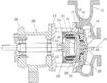
- FIG. 1is a cross-sectional elevation of a magnetically driven centrifugal pump taken through the axis of impeller rotation;
- FIG. 2is a cross-sectional detail of the stuffing box illustrated in FIG. 1 ;
- FIG. 3is a detail of the magnets and bushings in the stuffing box of FIG. 2 ;
- FIG. 4is a cross-sectional elevation of a second embodiment of a magnetically driven centrifugal pump taken through the axis of impeller rotation;
- FIG. 5is a cross-sectional detail of the stuffing box illustrated in FIG. 4 ;
- FIG. 6is a detail of the magnets and bushings in the stuffing box of FIG. 5 .
- FIGS. 1 through 3differ from the second embodiment, FIGS. 4 through 6 , by the support arrangements for the impeller.
- a bushingis about the hub of the impeller to securely support the rotatable impeller.
- a pump case 12 defining an impeller cavity and a voluteis further defined by a housing structure 13 .
- the pump case 12surrounds an open vane impeller 14 while the housing structure 13 extends over a stuffing box 16 .
- the impeller 14includes an impeller hub 15 extending away from the vanes of the impeller 14 .
- the pump case 12 and housing structure 13are conventionally assembled with bolts.
- the housing structure 13is shown in this instance to have an open arrangement with holes about the circumference.
- the stuffing box 16includes a stuffing box outer 18 which is a collar with an outer flange 19 engaging the pump case 12 and held in place by the housing structure 13 .
- the stuffing box 16further includes a stuffing box inner 20 engaged with the stuffing box outer 18 at a threaded engagement 22 .
- the threaded engagement 22provides for the stuffing box inner 20 to be rotated relative to the stuffing box outer 18 to allow axial translation of the stuffing box inner 20 relative to the stuffing box outer 18 and in turn the pump case 12 .
- the rotational position of the stuffing box innercan either be held by thread friction or by an external set screw.
- the stuffing box inner 20extends from the threaded engagement 22 as a cylinder to a stuffing box inner detachable cap 24 .
- the stuffing box inner detachable cap 24is held in place by fasteners.
- a rotor 26is located within the annular cavity defined within the stuffing box inner 20 .
- the rotor 26is also cylindrical with a front wall.
- a mounting hub 27 fixed on the cylindrical front wallthreadedly engages the impeller hub 15 so that the impeller 14 is detachably fixed to the rotor 26 .
- the rotor 26With the rotor 26 located in the annular cavity with thrust bushings described below, the rotor 26 moves axially with the stuffing box inner 20 relative to the stuffing box outer 18 .
- the axial adjustment of the stuffing box inner 20 relative to the stuffing box outer 18is used to create an appropriate clearance between the impeller 14 and the pump case 12 .
- a drive 28is arranged inwardly of the rotor 26 .
- the drive 28includes a drive output 29 that is cylindrical with an engagement to receive a drive shaft coupled with a motor (not shown) for torque transfer.
- the drivefurther includes a drive shaft power frame 30 with a shaft conventionally arranged in with bearings as shown to transfer rotary power from the motor.
- the housingis conventionally coupled with the housing structure 13 by bolts.
- the magnetic coupling 31is traditional including driving magnets 32 associated with the drive 28 and driven magnets 34 associated with the rotor 26 .
- a canister 36extends through the magnetic coupling.
- the canister 36is integrally formed with the stuffing box inner detachable cap 24 .
- the stuffing box inner detachable cap 24 and the associated canister 36are retained by fasteners at the end of the stuffing box inner 20 .
- the canister 36does not rotate with either the rotor 26 or the drive 28 but remains stationary in the pump unless the impeller 14 is being axially adjusted.
- the canister 36includes a concave end which results in less distortion of the canister 36 under pressure loads from the pump process fluids.
- the rotating components within the stuffing box 16are mounted through bushings.
- the bushings used in these embodimentsare bushing pairs each with a static bushing associated with the stuffing box inner 20 and a dynamic bushing each associated with the rotor/impeller assembly 26 / 14 . These components are held in place by conventional means.
- An annular journal rotor bushing 38is located between the stuffing box inner 20 and the rotor 26 .
- An annular journal impeller bushing 40is between and aligned radially of the stuffing box inner 20 and the impeller hub 15 .
- the mounting hub 27includes an outer ring 41 .
- the journal impeller bushing 40is engaged with the mounting hub 27 .
- a forward thrust bushing 42is arranged between the stuffing box inner detachable cap 24 and the rotor 26 .
- a rearward thrust bushing 44is located between the stuffing box wall 25 and the rotor 26 .
- the thrust bushings 42 , 44thus retain the rotor 26 fixed axially within the stuffing box inner 20 . Again, all of the journal and thrust bushings are traditionally placed within the pump.
- a process fluid shunt 46lubricates the bushings located about the rotor.
- a shunt inlet 48is located outwardly of the impeller hub 15 to extend through the journal impeller bushing 40 .
- a gap between the rotor 26 and the stuffing box wall 25directs process fluid through the rearward thrust bushing 44 .
- An annular gap between the stuffing box inner 20 and the rotor 26then permits the shunted process fluid to move to and through the journal rotor bushing 38 .
- An annular cavity adjacent the journal rotor bushing 38 defined in the stuffing box inner detachable cap 24then directs the shunted process fluid through the forward thrust bushing 42 .
- the shunted process fluidis then released to around the canister 36 where it passes by the wetted magnets 34 and then to the shunt return 50 along the access of impeller rotation 10 .
- the shunt inlet 48is located outwardly on the open vane impeller 14 of the shunt return 50 located along the access of impeller rotation 10 .
- rotation of the impeller 14is able to drive circulation of the shunted process fluid.
- a rub ring 52closes the drive end of the stuffing box inner 20 by extending inwardly to the drive 28 .
- the rub ring 52is associated with a circumferential ring 54 located on the drive 28 .
- the maximum compressive deformation in the ring 54is less than the gap between the canister 36 and either of the magnet assemblies 32 , 34 . This prevents damage to the canister 36 by catastrophic failure of any of the bearings.
Landscapes
- Engineering & Computer Science (AREA)
- Mechanical Engineering (AREA)
- General Engineering & Computer Science (AREA)
- Physics & Mathematics (AREA)
- Fluid Mechanics (AREA)
- Structures Of Non-Positive Displacement Pumps (AREA)
Abstract
Description
Claims (10)
Priority Applications (2)
| Application Number | Priority Date | Filing Date | Title |
|---|---|---|---|
| US15/799,572US10738782B2 (en) | 2016-11-01 | 2017-10-31 | Magnetically coupled sealless centrifugal pump |
| US16/834,655US11396890B2 (en) | 2016-11-01 | 2020-03-30 | Magnetically coupled sealless centrifugal pump |
Applications Claiming Priority (2)
| Application Number | Priority Date | Filing Date | Title |
|---|---|---|---|
| US201662416059P | 2016-11-01 | 2016-11-01 | |
| US15/799,572US10738782B2 (en) | 2016-11-01 | 2017-10-31 | Magnetically coupled sealless centrifugal pump |
Related Child Applications (1)
| Application Number | Title | Priority Date | Filing Date |
|---|---|---|---|
| US16/834,655ContinuationUS11396890B2 (en) | 2016-11-01 | 2020-03-30 | Magnetically coupled sealless centrifugal pump |
Publications (2)
| Publication Number | Publication Date |
|---|---|
| US20180119698A1 US20180119698A1 (en) | 2018-05-03 |
| US10738782B2true US10738782B2 (en) | 2020-08-11 |
Family
ID=62020431
Family Applications (2)
| Application Number | Title | Priority Date | Filing Date |
|---|---|---|---|
| US15/799,572Active2038-05-11US10738782B2 (en) | 2016-11-01 | 2017-10-31 | Magnetically coupled sealless centrifugal pump |
| US16/834,655ActiveUS11396890B2 (en) | 2016-11-01 | 2020-03-30 | Magnetically coupled sealless centrifugal pump |
Family Applications After (1)
| Application Number | Title | Priority Date | Filing Date |
|---|---|---|---|
| US16/834,655ActiveUS11396890B2 (en) | 2016-11-01 | 2020-03-30 | Magnetically coupled sealless centrifugal pump |
Country Status (8)
| Country | Link |
|---|---|
| US (2) | US10738782B2 (en) |
| EP (1) | EP3523539B1 (en) |
| JP (1) | JP6949975B2 (en) |
| CN (1) | CN110249135B (en) |
| AU (1) | AU2017353926B2 (en) |
| CA (1) | CA3041837C (en) |
| MX (1) | MX2019004713A (en) |
| WO (1) | WO2018085293A1 (en) |
Cited By (1)
| Publication number | Priority date | Publication date | Assignee | Title |
|---|---|---|---|---|
| US11396890B2 (en) | 2016-11-01 | 2022-07-26 | Psg California Llc | Magnetically coupled sealless centrifugal pump |
Families Citing this family (2)
| Publication number | Priority date | Publication date | Assignee | Title |
|---|---|---|---|---|
| CN110360127B (en)* | 2019-07-31 | 2024-06-04 | 艾迪机器(杭州)有限公司 | Leakage-free magnetic drive rotational flow pump |
| US11149723B2 (en)* | 2019-12-31 | 2021-10-19 | Psg California Llc | Diaphragm pump leak detection |
Citations (24)
| Publication number | Priority date | Publication date | Assignee | Title |
|---|---|---|---|---|
| US2956841A (en) | 1957-01-30 | 1960-10-18 | Westinghouse Electric Corp | Bearing and mounting therefor |
| US3877844A (en) | 1972-11-06 | 1975-04-15 | Franz Klaus | Pump |
| US4080112A (en) | 1976-02-03 | 1978-03-21 | March Manufacturing Company | Magnetically-coupled pump |
| US4645433A (en) | 1984-07-16 | 1987-02-24 | Cp Pumpen Ag | Sealing shroud centrifugal pump |
| US4661044A (en) | 1985-05-24 | 1987-04-28 | Goulds Pumps, Incorporated | Pump having a bushing removal mechanism |
| US4871301A (en)* | 1988-02-29 | 1989-10-03 | Ingersoll-Rand Company | Centrifugal pump bearing arrangement |
| GB2263312A (en) | 1992-01-17 | 1993-07-21 | Stork Pompen | Vertical pump with magnetic coupling. |
| US5368439A (en) | 1993-10-12 | 1994-11-29 | Price Pump Manufacturing Company | Magnetic drive pump with axially adjustable impeller |
| US5385445A (en) | 1993-12-03 | 1995-01-31 | Ingersoll-Dresser Pump Company | Centrifugal pump |
| US5501582A (en) | 1994-01-26 | 1996-03-26 | Le Carbone Lorraine | Magnetically driven centrifugal pump |
| US5547299A (en) | 1993-03-22 | 1996-08-20 | Siemens Nixdorf Informationssysteme Aktiengesellschaft | Device for the exact positioning of a printing head in relation to a recording substrate |
| US5779449A (en) | 1996-04-15 | 1998-07-14 | Ansimag Inc. | Separable, multipartite impeller assembly for centrifugal pumps |
| US5846049A (en)* | 1996-07-08 | 1998-12-08 | Endura Pumps International, Inc. | Modular containment apparatus for adjusting axial position of an impeller in a magnetically coupled apparatus |
| DE29822717U1 (en) | 1998-12-21 | 1999-03-18 | Feodor Burgmann Dichtungswerke GmbH & Co, 82515 Wolfratshausen | Centrifugal pump, in particular for pumping a coolant in a coolant circuit |
| US7137793B2 (en) | 2004-04-05 | 2006-11-21 | Peopleflo Manufacturing, Inc. | Magnetically driven gear pump |
| US7183683B2 (en) | 2005-06-23 | 2007-02-27 | Peopleflo Manufacturing Inc. | Inner magnet of a magnetic coupling |
| US7549205B2 (en) | 2005-06-24 | 2009-06-23 | Peopleflo Manufacturing Inc. | Assembly and method for pre-stressing a magnetic coupling canister |
| US8162630B2 (en) | 2006-03-31 | 2012-04-24 | H. Wernert & Co. Ohg | Rotary pump with coaxial magnetic coupling |
| US20120177511A1 (en) | 2011-01-10 | 2012-07-12 | Peopleflo Manufacturing, Inc. | Modular Pump Rotor Assemblies |
| CN104196763A (en) | 2014-07-01 | 2014-12-10 | 安徽盛唐泵阀制造有限公司 | Magnetic pump for conveying easily crystallized medium |
| US20150260191A1 (en) | 2014-03-11 | 2015-09-17 | Peopleflo Manufacturing, Inc. | Rotary device having a radial magnetic coupling |
| US20160084256A1 (en) | 2013-05-08 | 2016-03-24 | Ksb Aktiengesellschaft | Pump Arrangement |
| TWM527045U (en) | 2016-05-13 | 2016-08-11 | Flow Engineering Corp | Shaft-seal free magnetic-driven pump with cassette type bearing mechanism |
| US20170175757A1 (en)* | 2015-09-30 | 2017-06-22 | Peopleflo Manufacturing, Inc. | Rotodynamic Pumps that Resist Clogging |
Family Cites Families (17)
| Publication number | Priority date | Publication date | Assignee | Title |
|---|---|---|---|---|
| JPH11159492A (en) | 1997-12-01 | 1999-06-15 | Seikow Chemical Engineering & Machinery Ltd | Inner magnet structure of magnet coupling |
| DE59911579D1 (en)* | 1998-08-21 | 2005-03-17 | Cp Pumpen Ag Zofingen | Magnetically coupled centrifugal pump |
| JP5046449B2 (en)* | 2001-08-10 | 2012-10-10 | 株式会社サンメディカル技術研究所 | Blood pump |
| JP4681625B2 (en)* | 2008-02-22 | 2011-05-11 | 三菱重工業株式会社 | Blood pump and pump unit |
| CN101251119A (en)* | 2008-04-07 | 2008-08-27 | 蔡国华 | Magnetic drive pump |
| CN101430188B (en)* | 2008-11-04 | 2010-06-09 | 江苏大学 | Device and method for on-line monitoring of rotating shaft position of magnetic pump |
| CN201401343Y (en)* | 2009-05-13 | 2010-02-10 | 丹东克隆集团有限责任公司 | Magnetic pump |
| CN201401342Y (en)* | 2009-05-13 | 2010-02-10 | 丹东克隆集团有限责任公司 | High-high pressure area reflux cooling magnetic pump |
| EP2604863B1 (en)* | 2011-12-13 | 2017-07-19 | EagleBurgmann Germany GmbH & Co. KG | Rotary compessor |
| CN202441610U (en)* | 2012-01-16 | 2012-09-19 | 重庆乾泉泵阀制造有限公司 | Inverse heat preservation magnetic pump |
| CN104179693B (en)* | 2014-07-16 | 2018-01-02 | 苏州泰格动力机器有限公司 | A kind of magnetic drive pump |
| CN104153999B (en)* | 2014-07-29 | 2016-08-31 | 江苏大学 | A kind of pump integrated micro high-speed magnetic pump |
| US9920764B2 (en)* | 2015-09-30 | 2018-03-20 | Peopleflo Manufacturing, Inc. | Pump devices |
| CN205225759U (en)* | 2015-11-23 | 2016-05-11 | 江苏新腾宇流体设备制造有限公司 | Magnetic drive pump |
| CN105422471A (en)* | 2015-12-15 | 2016-03-23 | 江苏江大泵业制造有限公司 | Full-thermal insulation magnetic pump |
| CN110249135B (en) | 2016-11-01 | 2021-09-21 | Psg全球公司 | Magnetic coupling seal-free centrifugal pump |
| US10240600B2 (en) | 2017-04-26 | 2019-03-26 | Wilden Pump And Engineering Llc | Magnetically engaged pump |
- 2017
- 2017-10-31CNCN201780066503.0Apatent/CN110249135B/enactiveActive
- 2017-10-31AUAU2017353926Apatent/AU2017353926B2/enactiveActive
- 2017-10-31EPEP17867899.1Apatent/EP3523539B1/enactiveActive
- 2017-10-31MXMX2019004713Apatent/MX2019004713A/enunknown
- 2017-10-31WOPCT/US2017/059378patent/WO2018085293A1/ennot_activeCeased
- 2017-10-31CACA3041837Apatent/CA3041837C/enactiveActive
- 2017-10-31JPJP2019544804Apatent/JP6949975B2/enactiveActive
- 2017-10-31USUS15/799,572patent/US10738782B2/enactiveActive
- 2020
- 2020-03-30USUS16/834,655patent/US11396890B2/enactiveActive
Patent Citations (24)
| Publication number | Priority date | Publication date | Assignee | Title |
|---|---|---|---|---|
| US2956841A (en) | 1957-01-30 | 1960-10-18 | Westinghouse Electric Corp | Bearing and mounting therefor |
| US3877844A (en) | 1972-11-06 | 1975-04-15 | Franz Klaus | Pump |
| US4080112A (en) | 1976-02-03 | 1978-03-21 | March Manufacturing Company | Magnetically-coupled pump |
| US4645433A (en) | 1984-07-16 | 1987-02-24 | Cp Pumpen Ag | Sealing shroud centrifugal pump |
| US4661044A (en) | 1985-05-24 | 1987-04-28 | Goulds Pumps, Incorporated | Pump having a bushing removal mechanism |
| US4871301A (en)* | 1988-02-29 | 1989-10-03 | Ingersoll-Rand Company | Centrifugal pump bearing arrangement |
| GB2263312A (en) | 1992-01-17 | 1993-07-21 | Stork Pompen | Vertical pump with magnetic coupling. |
| US5547299A (en) | 1993-03-22 | 1996-08-20 | Siemens Nixdorf Informationssysteme Aktiengesellschaft | Device for the exact positioning of a printing head in relation to a recording substrate |
| US5368439A (en) | 1993-10-12 | 1994-11-29 | Price Pump Manufacturing Company | Magnetic drive pump with axially adjustable impeller |
| US5385445A (en) | 1993-12-03 | 1995-01-31 | Ingersoll-Dresser Pump Company | Centrifugal pump |
| US5501582A (en) | 1994-01-26 | 1996-03-26 | Le Carbone Lorraine | Magnetically driven centrifugal pump |
| US5779449A (en) | 1996-04-15 | 1998-07-14 | Ansimag Inc. | Separable, multipartite impeller assembly for centrifugal pumps |
| US5846049A (en)* | 1996-07-08 | 1998-12-08 | Endura Pumps International, Inc. | Modular containment apparatus for adjusting axial position of an impeller in a magnetically coupled apparatus |
| DE29822717U1 (en) | 1998-12-21 | 1999-03-18 | Feodor Burgmann Dichtungswerke GmbH & Co, 82515 Wolfratshausen | Centrifugal pump, in particular for pumping a coolant in a coolant circuit |
| US7137793B2 (en) | 2004-04-05 | 2006-11-21 | Peopleflo Manufacturing, Inc. | Magnetically driven gear pump |
| US7183683B2 (en) | 2005-06-23 | 2007-02-27 | Peopleflo Manufacturing Inc. | Inner magnet of a magnetic coupling |
| US7549205B2 (en) | 2005-06-24 | 2009-06-23 | Peopleflo Manufacturing Inc. | Assembly and method for pre-stressing a magnetic coupling canister |
| US8162630B2 (en) | 2006-03-31 | 2012-04-24 | H. Wernert & Co. Ohg | Rotary pump with coaxial magnetic coupling |
| US20120177511A1 (en) | 2011-01-10 | 2012-07-12 | Peopleflo Manufacturing, Inc. | Modular Pump Rotor Assemblies |
| US20160084256A1 (en) | 2013-05-08 | 2016-03-24 | Ksb Aktiengesellschaft | Pump Arrangement |
| US20150260191A1 (en) | 2014-03-11 | 2015-09-17 | Peopleflo Manufacturing, Inc. | Rotary device having a radial magnetic coupling |
| CN104196763A (en) | 2014-07-01 | 2014-12-10 | 安徽盛唐泵阀制造有限公司 | Magnetic pump for conveying easily crystallized medium |
| US20170175757A1 (en)* | 2015-09-30 | 2017-06-22 | Peopleflo Manufacturing, Inc. | Rotodynamic Pumps that Resist Clogging |
| TWM527045U (en) | 2016-05-13 | 2016-08-11 | Flow Engineering Corp | Shaft-seal free magnetic-driven pump with cassette type bearing mechanism |
Non-Patent Citations (7)
| Title |
|---|
| English translation of Bibliographic Data of TWM527045, Aug. 11, 2016-Flow Engineering Corp. |
| English translation of Bibliographic Data of TWM527045, Aug. 11, 2016—Flow Engineering Corp. |
| EPO Examination Report re App. 17867899.1-1007 dated Sep. 19, 2019. |
| International Search Report & Written Opinion re PCT/US17/59378, dated Jan. 26, 2018. |
| Machine Translation of relevant portions of Abstract and Detailed Description of TWM527045, Aug. 11, 2016-Flow Engineering Corp. |
| Machine Translation of relevant portions of Abstract and Detailed Description of TWM527045, Aug. 11, 2016—Flow Engineering Corp. |
| Supplementary EU Search Report re App. 17867899.1-1007 / 3523539 dated Aug. 27, 2019. |
Cited By (1)
| Publication number | Priority date | Publication date | Assignee | Title |
|---|---|---|---|---|
| US11396890B2 (en) | 2016-11-01 | 2022-07-26 | Psg California Llc | Magnetically coupled sealless centrifugal pump |
Also Published As
| Publication number | Publication date |
|---|---|
| BR112019007743A2 (en) | 2019-07-09 |
| MX2019004713A (en) | 2019-12-11 |
| CA3041837C (en) | 2021-08-10 |
| EP3523539A4 (en) | 2019-10-02 |
| CN110249135A (en) | 2019-09-17 |
| AU2017353926B2 (en) | 2020-04-30 |
| EP3523539A1 (en) | 2019-08-14 |
| US20200256340A1 (en) | 2020-08-13 |
| CA3041837A1 (en) | 2018-05-11 |
| AU2017353926A1 (en) | 2019-05-02 |
| WO2018085293A1 (en) | 2018-05-11 |
| US11396890B2 (en) | 2022-07-26 |
| EP3523539B1 (en) | 2020-08-12 |
| US20180119698A1 (en) | 2018-05-03 |
| JP6949975B2 (en) | 2021-10-13 |
| JP2019534423A (en) | 2019-11-28 |
| CN110249135B (en) | 2021-09-21 |
Similar Documents
| Publication | Publication Date | Title |
|---|---|---|
| US11396890B2 (en) | Magnetically coupled sealless centrifugal pump | |
| US2406947A (en) | Centrifugal pump | |
| US9520756B2 (en) | Linear electromechanical actuator | |
| US2942555A (en) | Combination pump and motor | |
| RU2679070C2 (en) | Pump arrangement | |
| US2958292A (en) | Canned motor | |
| US7239056B1 (en) | Low speed canned motor | |
| AU2014264822A1 (en) | Pump arrangement comprising a plain bearing arrangement | |
| EP3358195B1 (en) | Centrifugal compressor | |
| US11821433B2 (en) | Rotary machine with improved shaft | |
| JP5322028B2 (en) | Motor rotor | |
| US20230065642A1 (en) | Electric pump with isolated stator | |
| WO2017086345A1 (en) | Shaft coupling and pump device | |
| KR102088474B1 (en) | Pump arrangement | |
| US11399460B1 (en) | Blade rotation system | |
| US20050036895A1 (en) | Canned motor and pump | |
| JP2018127998A (en) | Pump device | |
| BR112019007743B1 (en) | CENTRIFUGAL PUMP WITHOUT MAGNETICALLY COUPLED SEALING | |
| CN207333283U (en) | Centrifugal pump | |
| CN110185651A (en) | Can axial lossless assembly and disassembly rolling bearing mounting structure | |
| RU2742704C1 (en) | Centrifugal pump keyless rotor | |
| WO2019202499A1 (en) | Centrifugal seal with suction recirculation control for slurry pumps |
Legal Events
| Date | Code | Title | Description |
|---|---|---|---|
| FEPP | Fee payment procedure | Free format text:ENTITY STATUS SET TO UNDISCOUNTED (ORIGINAL EVENT CODE: BIG.); ENTITY STATUS OF PATENT OWNER: LARGE ENTITY | |
| AS | Assignment | Owner name:PSG WORLDWIDE, INC., CALIFORNIA Free format text:ASSIGNMENT OF ASSIGNORS INTEREST;ASSIGNORS:BEACH, REX WARREN;ORTEGA, NICHOLAS WILLIAM;FARLEY, JAMES GREGORY;AND OTHERS;SIGNING DATES FROM 20180209 TO 20180212;REEL/FRAME:044947/0209 | |
| STPP | Information on status: patent application and granting procedure in general | Free format text:DOCKETED NEW CASE - READY FOR EXAMINATION | |
| STPP | Information on status: patent application and granting procedure in general | Free format text:NON FINAL ACTION MAILED | |
| STPP | Information on status: patent application and granting procedure in general | Free format text:RESPONSE TO NON-FINAL OFFICE ACTION ENTERED AND FORWARDED TO EXAMINER | |
| STPP | Information on status: patent application and granting procedure in general | Free format text:FINAL REJECTION MAILED | |
| STPP | Information on status: patent application and granting procedure in general | Free format text:RESPONSE AFTER FINAL ACTION FORWARDED TO EXAMINER | |
| STPP | Information on status: patent application and granting procedure in general | Free format text:NOTICE OF ALLOWANCE MAILED -- APPLICATION RECEIVED IN OFFICE OF PUBLICATIONS | |
| STPP | Information on status: patent application and granting procedure in general | Free format text:PUBLICATIONS -- ISSUE FEE PAYMENT RECEIVED | |
| STCF | Information on status: patent grant | Free format text:PATENTED CASE | |
| AS | Assignment | Owner name:PSG CALIFORNIA LLC, CALIFORNIA Free format text:CHANGE OF NAME;ASSIGNOR:WILDEN PUMP AND ENGINEERING, LLC;REEL/FRAME:055909/0283 Effective date:20190501 Owner name:WILDEN PUMP & ENGINEERING, LLC, CALIFORNIA Free format text:MERGER;ASSIGNOR:PSG WORLDWIDE, INC.;REEL/FRAME:055898/0926 Effective date:20190101 | |
| AS | Assignment | Owner name:PSG CALIFORNIA LLC, CALIFORNIA Free format text:CORRECTIVE ASSIGNMENT TO CORRECT THE ASSIGNEE NAME PREVIOUSLY RECORDED ON REEL 055899 FRAME 0008. ASSIGNOR(S) HEREBY CONFIRMS THE CHANGE OF NAME;ASSIGNOR:WILDEN PUMP AND ENGINEERING, LLC;REEL/FRAME:055966/0822 Effective date:20190501 | |
| FEPP | Fee payment procedure | Free format text:SURCHARGE FOR LATE PAYMENT, LARGE ENTITY (ORIGINAL EVENT CODE: M1554); ENTITY STATUS OF PATENT OWNER: LARGE ENTITY | |
| MAFP | Maintenance fee payment | Free format text:PAYMENT OF MAINTENANCE FEE, 4TH YEAR, LARGE ENTITY (ORIGINAL EVENT CODE: M1551); ENTITY STATUS OF PATENT OWNER: LARGE ENTITY Year of fee payment:4 |