US10737801B2 - Fan module with rotatable vane ring power system - Google Patents
Fan module with rotatable vane ring power systemDownload PDFInfo
- Publication number
- US10737801B2 US10737801B2US15/339,171US201615339171AUS10737801B2US 10737801 B2US10737801 B2US 10737801B2US 201615339171 AUS201615339171 AUS 201615339171AUS 10737801 B2US10737801 B2US 10737801B2
- Authority
- US
- United States
- Prior art keywords
- vane ring
- generator
- fan module
- fan
- rotation
- Prior art date
- Legal status (The legal status is an assumption and is not a legal conclusion. Google has not performed a legal analysis and makes no representation as to the accuracy of the status listed.)
- Active, expires
Links
- 230000004044responseEffects0.000claimsdescription11
- 230000004048modificationEffects0.000description3
- 238000012986modificationMethods0.000description3
- 238000002485combustion reactionMethods0.000description2
- 238000004519manufacturing processMethods0.000description2
- 230000001172regenerating effectEffects0.000description2
- 230000003416augmentationEffects0.000description1
- 239000000446fuelSubstances0.000description1
- 230000003993interactionEffects0.000description1
- 239000006249magnetic particleSubstances0.000description1
- 239000000203mixtureSubstances0.000description1
- 230000001737promoting effectEffects0.000description1
- 238000005086pumpingMethods0.000description1
Images


Classifications
- F—MECHANICAL ENGINEERING; LIGHTING; HEATING; WEAPONS; BLASTING
- F01—MACHINES OR ENGINES IN GENERAL; ENGINE PLANTS IN GENERAL; STEAM ENGINES
- F01D—NON-POSITIVE DISPLACEMENT MACHINES OR ENGINES, e.g. STEAM TURBINES
- F01D15/00—Adaptations of machines or engines for special use; Combinations of engines with devices driven thereby
- F01D15/10—Adaptations for driving, or combinations with, electric generators
- B—PERFORMING OPERATIONS; TRANSPORTING
- B64—AIRCRAFT; AVIATION; COSMONAUTICS
- B64D—EQUIPMENT FOR FITTING IN OR TO AIRCRAFT; FLIGHT SUITS; PARACHUTES; ARRANGEMENT OR MOUNTING OF POWER PLANTS OR PROPULSION TRANSMISSIONS IN AIRCRAFT
- B64D27/00—Arrangement or mounting of power plants in aircraft; Aircraft characterised by the type or position of power plants
- B64D27/02—Aircraft characterised by the type or position of power plants
- B64D27/16—Aircraft characterised by the type or position of power plants of jet type
- B64D27/18—Aircraft characterised by the type or position of power plants of jet type within, or attached to, wings
- B—PERFORMING OPERATIONS; TRANSPORTING
- B64—AIRCRAFT; AVIATION; COSMONAUTICS
- B64D—EQUIPMENT FOR FITTING IN OR TO AIRCRAFT; FLIGHT SUITS; PARACHUTES; ARRANGEMENT OR MOUNTING OF POWER PLANTS OR PROPULSION TRANSMISSIONS IN AIRCRAFT
- B64D27/00—Arrangement or mounting of power plants in aircraft; Aircraft characterised by the type or position of power plants
- B64D27/02—Aircraft characterised by the type or position of power plants
- B64D27/16—Aircraft characterised by the type or position of power plants of jet type
- B64D27/20—Aircraft characterised by the type or position of power plants of jet type within, or attached to, fuselages
- B—PERFORMING OPERATIONS; TRANSPORTING
- B64—AIRCRAFT; AVIATION; COSMONAUTICS
- B64D—EQUIPMENT FOR FITTING IN OR TO AIRCRAFT; FLIGHT SUITS; PARACHUTES; ARRANGEMENT OR MOUNTING OF POWER PLANTS OR PROPULSION TRANSMISSIONS IN AIRCRAFT
- B64D27/00—Arrangement or mounting of power plants in aircraft; Aircraft characterised by the type or position of power plants
- B64D27/02—Aircraft characterised by the type or position of power plants
- B64D27/24—Aircraft characterised by the type or position of power plants using steam or spring force
- B—PERFORMING OPERATIONS; TRANSPORTING
- B64—AIRCRAFT; AVIATION; COSMONAUTICS
- B64D—EQUIPMENT FOR FITTING IN OR TO AIRCRAFT; FLIGHT SUITS; PARACHUTES; ARRANGEMENT OR MOUNTING OF POWER PLANTS OR PROPULSION TRANSMISSIONS IN AIRCRAFT
- B64D41/00—Power installations for auxiliary purposes
- F—MECHANICAL ENGINEERING; LIGHTING; HEATING; WEAPONS; BLASTING
- F02—COMBUSTION ENGINES; HOT-GAS OR COMBUSTION-PRODUCT ENGINE PLANTS
- F02C—GAS-TURBINE PLANTS; AIR INTAKES FOR JET-PROPULSION PLANTS; CONTROLLING FUEL SUPPLY IN AIR-BREATHING JET-PROPULSION PLANTS
- F02C7/00—Features, components parts, details or accessories, not provided for in, or of interest apart form groups F02C1/00 - F02C6/00; Air intakes for jet-propulsion plants
- F02C7/36—Power transmission arrangements between the different shafts of the gas turbine plant, or between the gas-turbine plant and the power user
- B—PERFORMING OPERATIONS; TRANSPORTING
- B64—AIRCRAFT; AVIATION; COSMONAUTICS
- B64D—EQUIPMENT FOR FITTING IN OR TO AIRCRAFT; FLIGHT SUITS; PARACHUTES; ARRANGEMENT OR MOUNTING OF POWER PLANTS OR PROPULSION TRANSMISSIONS IN AIRCRAFT
- B64D2221/00—Electric power distribution systems onboard aircraft
- F—MECHANICAL ENGINEERING; LIGHTING; HEATING; WEAPONS; BLASTING
- F05—INDEXING SCHEMES RELATING TO ENGINES OR PUMPS IN VARIOUS SUBCLASSES OF CLASSES F01-F04
- F05D—INDEXING SCHEME FOR ASPECTS RELATING TO NON-POSITIVE-DISPLACEMENT MACHINES OR ENGINES, GAS-TURBINES OR JET-PROPULSION PLANTS
- F05D2220/00—Application
- F05D2220/30—Application in turbines
- F05D2220/34—Application in turbines in ram-air turbines ("RATS")
- F—MECHANICAL ENGINEERING; LIGHTING; HEATING; WEAPONS; BLASTING
- F05—INDEXING SCHEMES RELATING TO ENGINES OR PUMPS IN VARIOUS SUBCLASSES OF CLASSES F01-F04
- F05D—INDEXING SCHEME FOR ASPECTS RELATING TO NON-POSITIVE-DISPLACEMENT MACHINES OR ENGINES, GAS-TURBINES OR JET-PROPULSION PLANTS
- F05D2220/00—Application
- F05D2220/30—Application in turbines
- F05D2220/36—Application in turbines specially adapted for the fan of turbofan engines
Definitions
- the present disclosurerelates generally to aircraft propulsion systems, and more specifically to fan modules included in aircraft propulsion systems.
- Aircraft propulsion systemsmay include gas turbine engines that are used to power the aircraft.
- Gas turbine enginestypically include a compressor, a combustor, and a turbine.
- the compressorcompresses air drawn into the engine and delivers high pressure air to the combustor.
- fuelis mixed with the high pressure air and the mixture is ignited.
- Products of the combustion reaction in the combustorare directed into the turbine where work is extracted to drive the compressor and, sometimes, a fan module coupled to the turbine by an output shaft. Left-over products of the combustion reaction are exhausted out of the turbine and may provide thrust in some applications.
- Gas turbine enginesmay be used to power engine accessories and/or aircraft accessories. Depending on flight conditions, gas turbine engines may be required to provide thrust for the aircraft and/or power the accessories. Designing aircraft propulsion systems to satisfy aircraft thrust requirements while providing adequate power for accessories during various flight conditions remains an area of interest.
- the present disclosuremay comprise one or more of the following features and combinations thereof.
- a fan modulemay include a fan rotor, a vane ring, and a power supply system.
- the fan rotormay be configured to discharge thrust in an aft direction when rotated about a central axis.
- the vane ringmay be located aft of the fan rotor along the central axis and mounted for rotation about the central axis.
- the vane ringmay include a plurality of airfoils arranged to interact with the thrust discharged by the fan rotor so that the thrust drives rotation of the vane ring.
- the power supply systemmay include a generator selectively coupled to the vane ring to produce electrical power in response to rotation of the vane ring, a brake coupled to the vane ring to selectively block rotation of the vane ring about the central axis, and a controller coupled to the generator and the brake.
- the controllermay be configured to engage the brake to block rotation of the vane ring in a thrust mode of the fan module associated with relatively high-thrust conditions so that electrical power is not produced by the generator and to disengage the brake to permit rotation of the vane ring in a power mode of the fan module associated with relatively low-thrust conditions so that electrical power is produced by the generator.
- the plurality of airfoils of the vane ringmay provide a plurality of fan exit guide vanes arranged directly aft of the fan rotor that are constrained against rotation about the central axis during operation of the fan module in the thrust mode.
- the plurality of fan exit guide vanesmay be configured for rotation about the central axis during operation of the fan module in the power mode. Additionally, in some embodiments, rotation of the fan rotor about the central axis may be driven by operation of at least one of two gas turbine engines.
- the power supply systemmay include a torque transmitting device coupled between the vane ring and the generator, and the controller may be configured to control operation of the torque transmitting device to selectively transmit rotation from the vane ring to the generator.
- the controllermay be configured to at least partially engage the torque transmitting device to transmit rotation from the vane ring to the generator so that the generator produces electrical power in response to rotation of the vane ring about the central axis during operation of the fan module in the power mode.
- the controllermay be configured to disengage the torque transmitting device to de-couple the vane ring from the generator during operation of the fan module in the thrust mode.
- the controllermay be configured to monitor a load experienced by the generator during operation of the fan module in the power mode and to adjust engagement of the torque transmitting device based on the monitored load.
- a fan modulemay include a fan rotor, a vane ring, and a power supply system.
- the fan rotormay be configured for rotation about a central axis.
- the vane ringmay be mounted for rotation about the central axis.
- the power supply systemmay include a generator coupled to the vane ring and configured to produce electrical power in response to rotation of the vane ring and a brake coupled to the vane ring and configured to block or permit rotation of the vane ring.
- the power supply systemmay include a controller coupled to the generator and the brake, and the controller may be configured to engage the brake to block rotation of the vane ring about the central axis so that the vane ring does not drive the generator to produce electrical power and to disengage the brake to permit rotation of the vane ring about the central axis so that the vane ring drives the generator to produce electrical power.
- the controllermay be configured to engage the brake during operation of the fan module in a thrust mode in which pressurized air discharged by the fan rotor is generally directed along the central axis by the vane ring to produce thrust and to disengage the brake during operation of the fan module in a power mode in which pressurized air discharged by the fan rotor is not generally directed along the central axis by the vane ring to produce thrust.
- the power supply systemmay include a torque transmitting device coupled between the vane ring and the generator, and the controller may be configured to control operation of the torque transmitting device to transmit rotation from the vane ring to the generator during operation of the fan module in the power mode.
- the controllermay be configured to at least partially engage the torque transmitting device to transmit rotation from the vane ring to the generator so that the generator produces electrical power during operation of the fan module in the power mode.
- the controllermay be configured to monitor a load experienced by the generator during operation of the fan module in the power mode and to adjust engagement of the torque transmitting device based on the monitored load. Additionally, in some embodiments, rotation of the fan rotor about the central axis may be driven by operation of two gas turbine engines.
- an aircraftmay include an airframe, a plurality of gas turbine engines supported by the airframe, and a fan module supported by the airframe.
- the fan modulemay include a fan rotor, a vane ring, and a power supply system.
- the fan rotormay be coupled to the plurality of gas turbine engines and configured for rotation about a central axis.
- the vane ringmay be mounted for rotation about the central axis in response to rotation of the fan rotor about the central axis.
- the power supply systemmay have a generator selectively coupled to the vane ring, a brake coupled to the vane ring, and a controller coupled to the generator and the brake.
- the controllermay be configured to engage the brake to block rotation of the vane ring about the central axis so that the vane ring does not drive the generator to produce electrical power and to disengage the brake to permit rotation of the vane ring about the central axis so that the vane ring drives the generator to produce electrical power.
- the airframemay include a nose end and a tail end located aft of the nose end along the central axis
- the plurality of gas turbine enginesmay be located closer to the nose end of the airframe than the tail end of the airframe
- the fan modulemay be located closer to the tail end of the airframe than the nose end of the airframe.
- the controllermay be configured to engage the brake during operation of the aircraft in a thrust mode in which pressurized air discharged by the fan rotor is generally directed along the central axis by the vane ring to produce thrust and to disengage the brake during operation of the aircraft in a power mode in which pressurized air discharged by the fan rotor is not generally directed along the central axis by the vane ring to produce thrust.
- the power supply systemmay include a torque transmitting device coupled between the vane ring and the generator, and the controller may be configured to control operation of the torque transmitting device to selectively transmit rotation from the vane ring to the generator.
- the controllermay be configured to monitor a load experienced by the generator during operation of the aircraft and to adjust engagement of the torque transmitting device based on the monitored load when torque is transmitted from the vane ring to the generator to drive the generator to produce electrical power
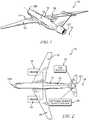
- FIG. 1is a perspective view of an aircraft showing that the aircraft includes an airframe, a pair of gas turbine engines supported by the airframe, and a fan module supported by the airframe;
- FIG. 2is a top view of the aircraft of FIG. 1 showing that the gas turbine engines are coupled to the fan module to drive the fan module and showing that the fan module includes an optional power supply system;
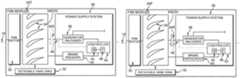
- FIG. 3is a diagrammatic view of the aircraft of FIG. 2 showing that the fan module includes a fan rotor coupled to the gas turbine engines and a vane ring mounted for rotation about a central axis in response to rotation of the fan rotor about the central axis, and showing that the power supply system includes a generator coupled to the vane ring, a brake coupled to the vane ring, and a controller coupled to the generator and the brake;
- FIG. 4is a partially diagrammatic view of the fan module depicted in FIG. 3 showing that the fan module is operable in a thrust mode in which the controller engages the brake to block rotation of the vane ring so that electrical power is not produced by the generator;
- FIG. 5is a partially diagrammatic view of the fan module depicted in FIG. 3 showing that the fan module is operable in a power mode in which the controller disengages the brake to permit rotation of the vane ring so that air from the fan rotor causes rotation of the vane ring and electrical power is produced by the generator;
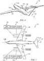
- FIG. 6is a perspective view of another aircraft showing that the aircraft includes an airframe, a pair of gas turbine engines supported by the airframe, and a pair of fan modules supported by the airframe; and
- FIG. 7is a top view of the aircraft of FIG. 6 showing that each of the gas turbine engines is coupled to one of the fan modules to drive the fan module and showing that each fan module includes an optional power supply system.
- an illustrative aircraft 10includes an airframe 12 and a pair of gas turbine engines 14 , 16 supported by the airframe 12 .
- the airframe 12has a nose end 12 N and a tail end 12 T located aft of the nose end 12 N along a central axis 18 .
- the gas turbine engines 14 , 16are substantially identical to one another and configured to drive a fan module 20 included in the aircraft 10 via at least one output shaft 22 that couples the engines 14 , 16 to the fan module 20 .
- the aircraft 10includes only two gas turbine engines 14 , 16 distributed along respective wings 24 , 26 thereof as shown in FIGS. 1 and 2 .
- the gas turbine engines 14 , 16are located closer to the nose end 12 N of the airframe 12 than the tail end 12 T of the airframe 12 .
- the fan module 20is located closer to the tail end 12 T than the nose end 12 N.
- the aircraft 10may include another suitable number of gas turbine engines distributed along the wings 24 , 26 to provide one or more distributed propulsion systems.
- the gas turbine engines 14 , 16 and the fan module 20may be arranged relative to one another in another suitable arrangement.
- the fan module 20may be arranged forward of the engines 14 , 16 along the central axis 18 in similar fashion to the arrangement of the fan modules 120 relative to the engines 114 , 116 along the central axis 118 as shown in FIGS. 6 and 7 .
- the illustrative fan module 20includes a fan rotor 30 and a vane ring 32 located aft of the fan rotor 30 along the central axis 18 .
- the fan rotor 30is configured to discharge thrust aftward along the axis 18 when driven to rotate about the axis 18 by at least one of the gas turbine engines 14 , 16 .
- the vane ring 32is mounted for rotation about the central axis 18 and includes airfoils 34 arranged to interact with the thrust discharged by the fan rotor 30 so that the thrust drives rotation of the vane ring 32 .
- the illustrative fan module 20also includes an optional power supply system 36 as shown in FIGS. 2 and 3 .
- the power supply system 36has a generator 38 , a brake 40 , and a controller 42 .
- the generator 38is coupled to the vane ring 32 to produce electrical power in response to rotation of the vane ring 32 about the central axis 18 .
- the brake 40is coupled to the vane ring 32 to selectively block rotation of the vane ring 32 about the central axis 18 .
- the controller 42is coupled to the generator 38 and the brake 40 and configured to engage the brake 40 in a thrust mode 20 T of the fan module 20 and disengage the brake 40 in a power mode 20 P of the fan module 20 .
- the thrust mode 20 T of the fan module 20is illustratively associated with relatively-high thrust conditions in which pressurized air discharged by the fan rotor 30 is generally directed along the central axis 18 by the vane ring 32 to produce thrust.
- the controller 42engages the brake 40 during operation of the module 20 in the thrust mode 20 T to block rotation of the vane ring 32 as shown in FIG. 4 . Because engagement of the brake 40 prevents the vane ring 32 from rotating and thereby driving the generator 38 to produce electrical power, electrical power is not supplied by the generator 38 to accessories of the engines 14 , 16 and/or the aircraft 10 in the thrust mode 20 T.
- the power mode 20 P of the fan module 20is illustratively associated with relatively-low thrust conditions in which pressurized air discharged by the fan rotor 30 is not generally directed along the central axis 18 by the vane ring 32 to produce thrust.
- the controller 42disengages the brake 40 during operation of the module 20 in the power mode 20 P to permit rotation of the vane ring 32 as shown in FIG. 5 . Because disengagement of the brake 40 allows the vane ring 32 to rotate and thereby drive the generator 38 to produce electrical power, electrical power is supplied by the generator 38 to accessories of the engines 14 , 16 and/or the aircraft 10 in the power mode 20 P.
- the vane ring 32may be said to act as a ram air turbine (RAT) during operation of the fan module 20 in the power mode 20 P.
- RATram air turbine
- the airfoils 34 of the vane ring 32provide fan exit guide vanes 34 EGV arranged directly aft of the fan rotor 30 along the central axis 18 as shown in FIGS. 4 and 5 .
- the guide vanes 34 EGVare constrained against rotation about the axis 18 when the brake 40 is engaged in the thrust mode 20 T of the fan module 20 as indicated by arrow 34 S.
- the guide vanes 34 EGVare configured for rotation about the axis 18 when the brake 40 is disengaged in the power mode 20 P of the module 20 as indicated by arrow 34 R.
- the generator 38is embodied as, or otherwise includes, a device configured to convert mechanical energy (i.e., rotational power) into electrical power as shown in FIG. 5 .
- the generator 38is embodied as, or otherwise includes, a device configured to convert rotational power provided by the vane ring 32 into electrical power for use by direct current (DC) and/or alternating current (AC) accessories of the engines 14 , 16 and/or the aircraft 10 .
- DCdirect current
- ACalternating current
- the brake 40is embodied as, or otherwise includes, a device configured to constrain the guide vanes 34 EGV against rotation about the central axis 18 when the device is engaged as shown in FIG. 4 .
- the brake 40may be embodied as, or otherwise include, a frictional brake such as a band brake, a drum brake, a disc brake, a or the like.
- the brake 40may be embodied as, or otherwise include, a pumping brake or an electromagnetic brake.
- the controller 42is embodied as, or otherwise includes, a device configured to control operation of the power supply system 36 (i.e., the generator 38 , the brake 40 , and any other components included therein).
- the controller 42includes memory 44 and a processor 46 coupled to the memory 44 as shown in FIG. 3 .
- the memory 44includes instructions that, when executed by the processor 46 , cause the processor 46 to perform various actions to control the components of the system 36 .
- the power supply system 36may include an optional torque transmitting device 48 coupled between the vane ring 32 and the generator 38 as shown in FIG. 3 .
- the torque transmitting device 48may be embodied as, or otherwise include, a device configured to selectively transmit rotation from the vane ring 32 to the generator 38 during operation of the fan module 20 .
- the torque transmitting device 48may be embodied as, or otherwise include, a friction clutch, a hydrodynamic clutch, an electromagnetic clutch, a magnetic particle clutch, or the like.
- the torque transmitting device 48may be coupled to the controller 42 and the controller 42 may be configured to control operation of the device 48 .
- the torque transmitting device 48may be omitted from the power supply system 36 .
- the vane ring 32would be directly coupled to the generator 38 .
- the power supply system 36may include one or more devices configured to monitor the operation of the generator 38 , the brake 40 , the torque transmitting device 48 , and any other components of the system 36 .
- the power supply system 36may include a sensor 38 S coupled to the generator 38 and configured to monitor one or more operational parameters of the generator 38 as shown in FIG. 3 .
- the sensor 38 Smay be configured to monitor the load experienced by the generator 38 during operation of the fan module 20 .
- the power supply system 36may include a sensor 40 S coupled to the brake 40 and configured to monitor one or more operational parameters of the brake 40 as shown in FIG. 3 .
- the sensor 40 Smay be configured to monitor the engagement state of the brake 40 .
- the power supply system 36may include a sensor 48 S coupled to the torque transmitting device 48 and configured to monitor one or more operational parameters of the device 48 as shown in FIG. 3 .
- the sensor 48 Smay be configured to monitor the engagement state of the torque transmitting device 48 .
- the illustrative power supply system 36may be adapted for use in an electric propulsion system, such as a distributed electric propulsion system.
- the electric propulsion systemmay be operated in some situations to drive a load and in other situations to provide a generator that produces electrical power that may be supplied to accessories of the propulsion system and/or the vehicle carrying the propulsion system.
- the aircraft 10may include more than one fan module 20 driven by at least one of the gas turbine engines 14 , 16 .
- one fan module 20may be driven by at least one of the engines 14 , 16 while another fan module 20 may be de-coupled from the engines 14 , 16 so that the another fan module 20 is not driven by at least one of the engines 14 , 16 .
- the one fan module 20may be driven by at least one of the engines 14 , 16 to produce thrust, whereas the another fan module 20 may be driven in response to ram air interaction to produce electrical power.
- operation of the fan module 20will be described in detail. Specifically, operation of the fan module 20 in the thrust mode 20 T is described below with reference to FIG. 4 and operation of the module 20 in the power mode 20 P is described below with reference to FIG. 5 .
- the controller 42controls the power supply system 36 to prevent production of electrical power by the generator 38 as shown in FIG. 4 .
- the instructions stored in the memory 44are executed by the processor 46 to cause the processor 46 to engage the brake 40 to constrain the vane ring 32 against rotation about the central axis 18 in the mode 20 T. Because the vane ring 32 is constrained against rotation, no rotation can be transmitted from the vane ring 32 to the generator 38 to drive the generator 38 to produce electrical power.
- the instructions stored in the memory 44also may be executed by the processor 46 to cause the processor 46 to disengage the torque transmitting device 48 to de-couple the vane ring 32 from the generator in the mode 20 T. Because the vane ring 32 is de-coupled from the generator 38 , the vane ring 32 is unable to drive the generator 38 to produce electrical power in the mode 20 T.
- the controller 42controls the power supply system 36 to allow production of electrical power by the generator 38 as shown in FIG. 5 .
- the instructions stored in the memory 44are executed by the processor 46 to cause the processor 46 to disengage the brake 40 to allow the vane ring 32 to rotate about the central axis 18 in the mode 20 P.
- the instructions stored in the memory 44also may be executed by the processor 46 to cause the processor 46 to at least partially engage the torque transmitting device 48 to couple the vane ring 32 to the generator 38 in the mode 20 P. Because the vane ring 32 is driven to rotate about the axis 18 , and because the vane ring 32 is coupled to the generator 38 , the generator 38 produces electrical power in the mode 20 P.
- the controller 42may control the power supply system 36 to adjust engagement of the torque transmitting device 48 as suggested by FIG. 5 .
- the instructions stored in the memory 44may be executed by the processor 46 to cause the processor 46 to monitor the load experienced by the generator 38 in the mode 20 P.
- the instructions stored in the memory 44also may be executed by the processor 46 to cause the processor 46 to adjust engagement of the torque transmitting device 48 based on the monitored load of the generator 38 in the mode 20 P.
- the instructions stored in the memory 44may be executed by the processor 46 to cause the processor 46 to adjust engagement of the device 48 so that the monitored load of the generator 38 does not exceed a maximum load thereof.
- Future configurations of turbofan-powered air vehiclesmay have greater power offtake requirements (e.g., power supplied to the accessories by the generator 38 ) than in current configurations.
- Increasing power offtake requirementsmay increase the demand placed upon propulsion systems (e.g., the gas turbine engines 14 , 16 and the fan module 20 ) such that compromises in mission systems and/or mission performance capabilities may be required to provide adequate thrust and power offtake.
- Such compromisesmay be necessary at high altitude flight conditions where achieving engine power offtake requirements may be more demanding of propulsion systems than achieving thrust requirements at altitude.
- operatorsmay be required to choose between flying at high altitude conditions and shutting down electronic systems or flying at altitude and powering electronic systems.
- Oversizing a turbofan propulsion system to provide adequate thrust and power offtakemay be undesirable in some situations.
- the present disclosuremay provide a design of a turbofan propulsion system that avoids the drawbacks associated with such oversizing while satisfying thrust and power offtake requirements.
- the present designmay involve modification to the fan exit guide vanes (EGVs).
- Traditional fan EGVsmay be stationary and used substantially to redirect flow along the axial direction (e.g., along the central axis 18 ) to maximize thrust.
- the present designmay allow the fan EGVs (e.g., the fan exit guide vanes 34 EGV) to rotate to power an electric generator (e.g., the generator 38 ).
- a brakee.g., the brake 40
- the brakemay be engaged to keep the fan EGVs stationary, thereby allowing the EGVs to augment flow and produce thrust as traditionally used.
- the brakemay be disengaged to allow the EGVs to absorb energy from the flow in order to power the generator.
- the fan EGVsmay be used as a ram air turbine (RAT) when thrust is not needed.
- RATram air turbine
- Augmentation of inlet and/or exhaust areasmay be used to minimize possible negative impacts on performance.
- inlet/exhaust area modificationmay be used to minimize ram drag, spillage drag, and boat tail drag.
- the present designmay be used in a wide range of air vehicle applications including single and multi-engine applications as well as both distributed mechanical and electrical applications.
- Use of the present design in a distributed electric propulsion system applicationmay allow the propulsion system to be used in regenerative cycles, in similar fashion to regenerative braking of hybrid vehicles.
- use of the present designmay allow one or more fans to be disconnected from the gas turbine engine(s) driving the fans, thereby allowing the engine(s) to throttle back and the fans to act as turbines in order to charge power cells or power electronic systems.
- Use of the present design in a distributed mechanical propulsion system applicationmay involve one or more fans being clutched, thereby allowing one or more fans to be operated in RAT mode to extract power from the flow instead of producing thrust.
Landscapes
- Engineering & Computer Science (AREA)
- Aviation & Aerospace Engineering (AREA)
- Mechanical Engineering (AREA)
- General Engineering & Computer Science (AREA)
- Chemical & Material Sciences (AREA)
- Combustion & Propulsion (AREA)
- Connection Of Motors, Electrical Generators, Mechanical Devices, And The Like (AREA)
Abstract
Description
Claims (11)
Priority Applications (3)
| Application Number | Priority Date | Filing Date | Title |
|---|---|---|---|
| US15/339,171US10737801B2 (en) | 2016-10-31 | 2016-10-31 | Fan module with rotatable vane ring power system |
| CA2980491ACA2980491A1 (en) | 2016-10-31 | 2017-09-27 | Fan module with rotatable vane ring power system |
| EP17194560.3AEP3315747B1 (en) | 2016-10-31 | 2017-10-03 | Fan module with rotatable vane ring power system |
Applications Claiming Priority (1)
| Application Number | Priority Date | Filing Date | Title |
|---|---|---|---|
| US15/339,171US10737801B2 (en) | 2016-10-31 | 2016-10-31 | Fan module with rotatable vane ring power system |
Publications (2)
| Publication Number | Publication Date |
|---|---|
| US20180118368A1 US20180118368A1 (en) | 2018-05-03 |
| US10737801B2true US10737801B2 (en) | 2020-08-11 |
Family
ID=60021926
Family Applications (1)
| Application Number | Title | Priority Date | Filing Date |
|---|---|---|---|
| US15/339,171Active2038-08-31US10737801B2 (en) | 2016-10-31 | 2016-10-31 | Fan module with rotatable vane ring power system |
Country Status (3)
| Country | Link |
|---|---|
| US (1) | US10737801B2 (en) |
| EP (1) | EP3315747B1 (en) |
| CA (1) | CA2980491A1 (en) |
Cited By (9)
| Publication number | Priority date | Publication date | Assignee | Title |
|---|---|---|---|---|
| US11686211B2 (en) | 2021-08-25 | 2023-06-27 | Rolls-Royce Corporation | Variable outlet guide vanes |
| US11788429B2 (en) | 2021-08-25 | 2023-10-17 | Rolls-Royce Corporation | Variable tandem fan outlet guide vanes |
| US11802490B2 (en) | 2021-08-25 | 2023-10-31 | Rolls-Royce Corporation | Controllable variable fan outlet guide vanes |
| US11879343B2 (en) | 2021-08-25 | 2024-01-23 | Rolls-Royce Corporation | Systems for controlling variable outlet guide vanes |
| US12292056B2 (en) | 2023-03-17 | 2025-05-06 | Rolls-Royce North American Technologies Inc. | Segmented variable fan outlet guide vane with gear assembly |
| US12320260B2 (en) | 2023-03-17 | 2025-06-03 | Rolls-Royce North American Technologies Inc. | Segmented variable fan outlet guide vane with cam assembly and unique actuation mechanisms |
| US12398648B2 (en) | 2023-03-17 | 2025-08-26 | Rolls-Royce North American Technologies Inc. | Segmented variable fan outlet guide vane with cam assembly and pass through actuation mechanisms |
| US12398655B2 (en) | 2023-03-17 | 2025-08-26 | Rolls-Royce North American Technologies Inc. | Segmented variable fan outlet guide vane with segment interface components |
| US12428974B2 (en) | 2023-03-17 | 2025-09-30 | Rolls-Royce North American Technologies Inc. | Segmented variable fan outlet guide vane with unique actuation mechanisms |
Families Citing this family (4)
| Publication number | Priority date | Publication date | Assignee | Title |
|---|---|---|---|---|
| US10737801B2 (en)* | 2016-10-31 | 2020-08-11 | Rolls-Royce Corporation | Fan module with rotatable vane ring power system |
| US10823056B2 (en)* | 2016-12-07 | 2020-11-03 | Raytheon Technologies Corporation | Boundary layer excitation aft fan gas turbine engine |
| US10724395B2 (en)* | 2018-10-01 | 2020-07-28 | Raytheon Technologies Corporation | Turbofan with motorized rotating inlet guide vane |
| US11846196B2 (en)* | 2020-02-21 | 2023-12-19 | Rtx Corporation | After-fan system with electrical motor for gas turbine engines |
Citations (69)
| Publication number | Priority date | Publication date | Assignee | Title |
|---|---|---|---|---|
| US2605849A (en) | 1947-10-09 | 1952-08-05 | Cons Vultee Aircraft Corp | Automatic propeller feathering system |
| US2732019A (en) | 1956-01-24 | stebbins | ||
| US3161237A (en) | 1960-03-25 | 1964-12-15 | Turbomeca Soc | Control method and system for aircraft powerplants comprising a gas turbine driving avariable pitch propelling device |
| US4222235A (en)* | 1977-07-25 | 1980-09-16 | General Electric Company | Variable cycle engine |
| US4242864A (en)* | 1978-05-25 | 1981-01-06 | The United States Of America As Represented By The Administrator Of The National Aeronautics And Space Administration | Integrated control system for a gas turbine engine |
| US4258545A (en)* | 1978-06-15 | 1981-03-31 | General Electric Company | Optimal control for a gas turbine engine |
| US4688995A (en)* | 1985-04-17 | 1987-08-25 | Rolls-Royce Plc | Propeller module for an aero gas turbine engine |
| US4728261A (en)* | 1985-11-02 | 1988-03-01 | Rolls-Royce Plc | Propeller module for an aero gas turbine engine |
| US4734007A (en)* | 1987-03-03 | 1988-03-29 | Rolls-Royce Plc | Fan casing and fan blade loading/unloading |
| US4738589A (en)* | 1986-02-25 | 1988-04-19 | Rolls-Royce Plc | Propeller module for an aero gas turbine engine |
| US4810164A (en)* | 1986-12-24 | 1989-03-07 | Rolls-Royce Plc | Pitch change arrangement for a variable pitch fan |
| US4936748A (en)* | 1988-11-28 | 1990-06-26 | General Electric Company | Auxiliary power source in an unducted fan gas turbine engine |
| US4968217A (en)* | 1989-09-06 | 1990-11-06 | Rolls-Royce Plc | Variable pitch arrangement for a gas turbine engine |
| US4998995A (en)* | 1988-05-05 | 1991-03-12 | British Aerospace Public Limited Company | Aircraft of split turbo-prop configuration |
| US5090869A (en)* | 1989-05-17 | 1992-02-25 | Rolls-Royce Plc | Variable pitch propeller module for an aero gas turbine engine powerplant |
| US5364231A (en)* | 1992-12-22 | 1994-11-15 | Alliedsignal Inc. | Full authority propeller pitch control |
| US5911679A (en)* | 1996-12-31 | 1999-06-15 | General Electric Company | Variable pitch rotor assembly for a gas turbine engine inlet |
| US6343768B1 (en)* | 2000-05-16 | 2002-02-05 | Patrick John Muldoon | Vertical/short take-off and landing aircraft |
| US6748744B2 (en)* | 2001-11-21 | 2004-06-15 | Pratt & Whitney Canada Corp. | Method and apparatus for the engine control of output shaft speed |
| US20060174629A1 (en)* | 2004-08-24 | 2006-08-10 | Honeywell International, Inc | Method and system for coordinating engine operation with electrical power extraction in a more electric vehicle |
| GB2423509A (en) | 2005-02-25 | 2006-08-30 | Boeing Co | Vertical and short take-off and landing aircraft |
| US7107756B2 (en)* | 2003-04-10 | 2006-09-19 | Rolls-Royce Plc | Turbofan arrangement |
| WO2006113877A2 (en) | 2005-04-20 | 2006-10-26 | Lugg Richard H | Hybrid jet/electric vtol aircraft |
| EP1918564A2 (en) | 2006-10-25 | 2008-05-07 | United Technologies Corporation | Rotor brake and windmilling lubrication system for geared turbofan engine |
| US20080121756A1 (en)* | 2006-11-24 | 2008-05-29 | The Boeing Company | Unconventional Integrated Propulsion Systems and Methods for Blended Wing Body Aircraft |
| US7406370B2 (en)* | 2004-08-24 | 2008-07-29 | Honeywell International Inc. | Electrical energy management system on a more electric vehicle |
| US20080253881A1 (en)* | 2006-09-09 | 2008-10-16 | Rolls-Royce Plc | Engine |
| US20090139202A1 (en)* | 2007-11-29 | 2009-06-04 | United Technologies Corporation | Convertible gas turbine propulsion system |
| US7555893B2 (en)* | 2005-01-25 | 2009-07-07 | Japan Aerospace Exploration Agency | Aircraft propulsion system |
| US7584923B2 (en)* | 2004-01-08 | 2009-09-08 | Robert Graham Burrage | Tilt-rotor aircraft |
| US20090289516A1 (en)* | 2008-05-22 | 2009-11-26 | Rolls-Royce Plc | Electrical generator arrangement |
| US20090289456A1 (en)* | 2008-05-23 | 2009-11-26 | Rolls-Royce Plc | Gas turbine engine apparatus |
| US20100047068A1 (en)* | 2007-02-10 | 2010-02-25 | Rolls-Royce Plc | Aeroengine |
| US20100124500A1 (en)* | 2008-11-14 | 2010-05-20 | Snecma | Turbomachine having an unducted fan provided with air guide means |
| US20100133832A1 (en)* | 2008-11-28 | 2010-06-03 | Rolls-Royce Plc | Aeroengine starter/generator arrangement |
| US7730714B2 (en)* | 2005-11-29 | 2010-06-08 | General Electric Company | Turbofan gas turbine engine with variable fan outlet guide vanes |
| US20100155526A1 (en)* | 2008-12-23 | 2010-06-24 | Rolls-Royce Deutschland Ltd & Co Kg | Aircraft with tail propeller-engine layout |
| US20100186418A1 (en)* | 2009-01-23 | 2010-07-29 | Snecma | Turbine engine with a power turbine equipped with an electric power generator centered on the axis of the turbine engine |
| US20100206982A1 (en)* | 2009-02-13 | 2010-08-19 | The Boeing Company | Counter rotating fan design and variable blade row spacing optimization for low environmental impact |
| US20100251726A1 (en)* | 2007-01-17 | 2010-10-07 | United Technologies Corporation | Turbine engine transient power extraction system and method |
| US7901185B2 (en)* | 2007-02-21 | 2011-03-08 | United Technologies Corporation | Variable rotor blade for gas turbine engine |
| US20120128487A1 (en)* | 2010-11-24 | 2012-05-24 | David John Howard Eames | Remote shaft driven open rotor propulsion system with electrical power generation |
| EP2458160A2 (en) | 2010-11-29 | 2012-05-30 | Pratt & Whitney Canada Corp. | Aircraft gas turbine engine comprising a generator |
| US8240124B2 (en)* | 2007-02-19 | 2012-08-14 | Snecma | Method of taking off auxiliary power from an airplane turbojet, and a turbojet fitted to implement such a method |
| US8322647B2 (en)* | 2006-08-24 | 2012-12-04 | American Dynamics Flight Systems, Inc. | High torque aerial lift (HTAL) |
| US20120304619A1 (en)* | 2010-02-16 | 2012-12-06 | Michael Alan Beachy Head | Engine for thrust or shaft output and corresponding operating method |
| US20130019585A1 (en)* | 2007-05-11 | 2013-01-24 | Brian Merry | Variable fan inlet guide vane for turbine engine |
| US20130104523A1 (en)* | 2011-10-28 | 2013-05-02 | Daniel B. Kupratis | Gas turbine engine with auxiliary fan |
| EP2730501A2 (en) | 2012-11-12 | 2014-05-14 | The Boeing Company | Rotational annular airscrew with integrated acoustic arrester |
| US20140260182A1 (en)* | 2013-03-14 | 2014-09-18 | United Technologies Corporation | Free stream intake for reverse core engine |
| DE102013209538A1 (en) | 2013-05-23 | 2014-11-27 | Robert Bosch Gmbh | Hybrid propulsion for powered aircraft, powered aircraft with hybrid drive and related operating procedures |
| US20140377079A1 (en)* | 2013-06-21 | 2014-12-25 | Hamilton Sundstrand Corporation | Propeller rotor and engine overspeed control |
| US8978356B2 (en)* | 2010-12-03 | 2015-03-17 | The Boeing Company | Thrust reverser and variable area fan nozzle actuation system and method |
| US20150078888A1 (en)* | 2013-09-19 | 2015-03-19 | The Boeing Company | Contra-rotating open fan propulsion system |
| US9163583B2 (en)* | 2013-05-01 | 2015-10-20 | Rohr, Inc. | System, apparatus, and method for thrust vectoring |
| EP2962885A1 (en) | 2013-02-28 | 2016-01-06 | Axter Aerospace SL | Hybrid power system for piston engine aircrafts |
| US20160023773A1 (en)* | 2014-07-23 | 2016-01-28 | Hamilton Sundstrand Corporation | Hybrid electric pulsed-power propulsion system for aircraft |
| US20160069275A1 (en)* | 2012-08-09 | 2016-03-10 | Snecma | Turbomachine comprising a plurality of fixed radial blades mounted upstream of the fan |
| US20160214727A1 (en)* | 2015-01-23 | 2016-07-28 | General Electric Company | Gas-electric propulsion system for an aircraft |
| US9527588B1 (en)* | 2012-09-28 | 2016-12-27 | Scott B. Rollefstad | Unmanned aircraft system (UAS) with active energy harvesting and power management |
| US9561860B2 (en)* | 2014-08-29 | 2017-02-07 | Tzunum, Inc. | System and methods for implementing regional air transit network using hybrid-electric aircraft |
| US20170081037A1 (en)* | 2015-09-21 | 2017-03-23 | General Electric Company | Aft engine nacelle shape for an aircraft |
| US9637217B2 (en)* | 2015-09-21 | 2017-05-02 | General Electric Company | Aircraft having an aft engine |
| US20170175753A1 (en)* | 2014-06-25 | 2017-06-22 | Safran Aircraft Engines | Turbomachine comprising a means of uncoupling a fan |
| US9834305B2 (en)* | 2013-05-03 | 2017-12-05 | Aerovironment, Inc. | Vertical takeoff and landing (VTOL) air vehicle |
| US20180050796A1 (en)* | 2016-08-19 | 2018-02-22 | Bell Helicopter Textron Inc. | Braking Systems for Rotorcraft |
| US20180057150A1 (en)* | 2016-08-23 | 2018-03-01 | General Electric Company | Deployable assembly for a propulsor |
| US20180118363A1 (en)* | 2016-10-31 | 2018-05-03 | Rolls-Royce Corporation | Fan module with adjustable pitch blades and power system |
| US20180118368A1 (en)* | 2016-10-31 | 2018-05-03 | Rolls-Royce Corporation | Fan module with rotatable vane ring power system |
- 2016
- 2016-10-31USUS15/339,171patent/US10737801B2/enactiveActive
- 2017
- 2017-09-27CACA2980491Apatent/CA2980491A1/ennot_activeAbandoned
- 2017-10-03EPEP17194560.3Apatent/EP3315747B1/enactiveActive
Patent Citations (72)
| Publication number | Priority date | Publication date | Assignee | Title |
|---|---|---|---|---|
| US2732019A (en) | 1956-01-24 | stebbins | ||
| US2605849A (en) | 1947-10-09 | 1952-08-05 | Cons Vultee Aircraft Corp | Automatic propeller feathering system |
| US3161237A (en) | 1960-03-25 | 1964-12-15 | Turbomeca Soc | Control method and system for aircraft powerplants comprising a gas turbine driving avariable pitch propelling device |
| US4222235A (en)* | 1977-07-25 | 1980-09-16 | General Electric Company | Variable cycle engine |
| US4242864A (en)* | 1978-05-25 | 1981-01-06 | The United States Of America As Represented By The Administrator Of The National Aeronautics And Space Administration | Integrated control system for a gas turbine engine |
| US4258545A (en)* | 1978-06-15 | 1981-03-31 | General Electric Company | Optimal control for a gas turbine engine |
| US4688995A (en)* | 1985-04-17 | 1987-08-25 | Rolls-Royce Plc | Propeller module for an aero gas turbine engine |
| US4728261A (en)* | 1985-11-02 | 1988-03-01 | Rolls-Royce Plc | Propeller module for an aero gas turbine engine |
| US4738589A (en)* | 1986-02-25 | 1988-04-19 | Rolls-Royce Plc | Propeller module for an aero gas turbine engine |
| US4810164A (en)* | 1986-12-24 | 1989-03-07 | Rolls-Royce Plc | Pitch change arrangement for a variable pitch fan |
| US4734007A (en)* | 1987-03-03 | 1988-03-29 | Rolls-Royce Plc | Fan casing and fan blade loading/unloading |
| US4998995A (en)* | 1988-05-05 | 1991-03-12 | British Aerospace Public Limited Company | Aircraft of split turbo-prop configuration |
| US4936748A (en)* | 1988-11-28 | 1990-06-26 | General Electric Company | Auxiliary power source in an unducted fan gas turbine engine |
| US5090869A (en)* | 1989-05-17 | 1992-02-25 | Rolls-Royce Plc | Variable pitch propeller module for an aero gas turbine engine powerplant |
| US4968217A (en)* | 1989-09-06 | 1990-11-06 | Rolls-Royce Plc | Variable pitch arrangement for a gas turbine engine |
| US5364231A (en)* | 1992-12-22 | 1994-11-15 | Alliedsignal Inc. | Full authority propeller pitch control |
| US5911679A (en)* | 1996-12-31 | 1999-06-15 | General Electric Company | Variable pitch rotor assembly for a gas turbine engine inlet |
| US6343768B1 (en)* | 2000-05-16 | 2002-02-05 | Patrick John Muldoon | Vertical/short take-off and landing aircraft |
| US6748744B2 (en)* | 2001-11-21 | 2004-06-15 | Pratt & Whitney Canada Corp. | Method and apparatus for the engine control of output shaft speed |
| US7107756B2 (en)* | 2003-04-10 | 2006-09-19 | Rolls-Royce Plc | Turbofan arrangement |
| US7584923B2 (en)* | 2004-01-08 | 2009-09-08 | Robert Graham Burrage | Tilt-rotor aircraft |
| US20060174629A1 (en)* | 2004-08-24 | 2006-08-10 | Honeywell International, Inc | Method and system for coordinating engine operation with electrical power extraction in a more electric vehicle |
| US7406370B2 (en)* | 2004-08-24 | 2008-07-29 | Honeywell International Inc. | Electrical energy management system on a more electric vehicle |
| US7555893B2 (en)* | 2005-01-25 | 2009-07-07 | Japan Aerospace Exploration Agency | Aircraft propulsion system |
| GB2423509A (en) | 2005-02-25 | 2006-08-30 | Boeing Co | Vertical and short take-off and landing aircraft |
| WO2006113877A2 (en) | 2005-04-20 | 2006-10-26 | Lugg Richard H | Hybrid jet/electric vtol aircraft |
| US7730714B2 (en)* | 2005-11-29 | 2010-06-08 | General Electric Company | Turbofan gas turbine engine with variable fan outlet guide vanes |
| US8322647B2 (en)* | 2006-08-24 | 2012-12-04 | American Dynamics Flight Systems, Inc. | High torque aerial lift (HTAL) |
| US20080253881A1 (en)* | 2006-09-09 | 2008-10-16 | Rolls-Royce Plc | Engine |
| EP1918564A2 (en) | 2006-10-25 | 2008-05-07 | United Technologies Corporation | Rotor brake and windmilling lubrication system for geared turbofan engine |
| US20080121756A1 (en)* | 2006-11-24 | 2008-05-29 | The Boeing Company | Unconventional Integrated Propulsion Systems and Methods for Blended Wing Body Aircraft |
| US20100251726A1 (en)* | 2007-01-17 | 2010-10-07 | United Technologies Corporation | Turbine engine transient power extraction system and method |
| US20100047068A1 (en)* | 2007-02-10 | 2010-02-25 | Rolls-Royce Plc | Aeroengine |
| US8240124B2 (en)* | 2007-02-19 | 2012-08-14 | Snecma | Method of taking off auxiliary power from an airplane turbojet, and a turbojet fitted to implement such a method |
| US7901185B2 (en)* | 2007-02-21 | 2011-03-08 | United Technologies Corporation | Variable rotor blade for gas turbine engine |
| US20130019585A1 (en)* | 2007-05-11 | 2013-01-24 | Brian Merry | Variable fan inlet guide vane for turbine engine |
| US20090139202A1 (en)* | 2007-11-29 | 2009-06-04 | United Technologies Corporation | Convertible gas turbine propulsion system |
| US20090289516A1 (en)* | 2008-05-22 | 2009-11-26 | Rolls-Royce Plc | Electrical generator arrangement |
| US20090289456A1 (en)* | 2008-05-23 | 2009-11-26 | Rolls-Royce Plc | Gas turbine engine apparatus |
| US20100124500A1 (en)* | 2008-11-14 | 2010-05-20 | Snecma | Turbomachine having an unducted fan provided with air guide means |
| US20100133832A1 (en)* | 2008-11-28 | 2010-06-03 | Rolls-Royce Plc | Aeroengine starter/generator arrangement |
| US20100155526A1 (en)* | 2008-12-23 | 2010-06-24 | Rolls-Royce Deutschland Ltd & Co Kg | Aircraft with tail propeller-engine layout |
| US20100186418A1 (en)* | 2009-01-23 | 2010-07-29 | Snecma | Turbine engine with a power turbine equipped with an electric power generator centered on the axis of the turbine engine |
| US20100206982A1 (en)* | 2009-02-13 | 2010-08-19 | The Boeing Company | Counter rotating fan design and variable blade row spacing optimization for low environmental impact |
| US20120304619A1 (en)* | 2010-02-16 | 2012-12-06 | Michael Alan Beachy Head | Engine for thrust or shaft output and corresponding operating method |
| US20120128487A1 (en)* | 2010-11-24 | 2012-05-24 | David John Howard Eames | Remote shaft driven open rotor propulsion system with electrical power generation |
| US8701381B2 (en) | 2010-11-24 | 2014-04-22 | Rolls-Royce Corporation | Remote shaft driven open rotor propulsion system with electrical power generation |
| EP2458160A2 (en) | 2010-11-29 | 2012-05-30 | Pratt & Whitney Canada Corp. | Aircraft gas turbine engine comprising a generator |
| US8978356B2 (en)* | 2010-12-03 | 2015-03-17 | The Boeing Company | Thrust reverser and variable area fan nozzle actuation system and method |
| US20130104523A1 (en)* | 2011-10-28 | 2013-05-02 | Daniel B. Kupratis | Gas turbine engine with auxiliary fan |
| US20160069275A1 (en)* | 2012-08-09 | 2016-03-10 | Snecma | Turbomachine comprising a plurality of fixed radial blades mounted upstream of the fan |
| US9527588B1 (en)* | 2012-09-28 | 2016-12-27 | Scott B. Rollefstad | Unmanned aircraft system (UAS) with active energy harvesting and power management |
| EP2730501A2 (en) | 2012-11-12 | 2014-05-14 | The Boeing Company | Rotational annular airscrew with integrated acoustic arrester |
| EP2962885A1 (en) | 2013-02-28 | 2016-01-06 | Axter Aerospace SL | Hybrid power system for piston engine aircrafts |
| US9644537B2 (en) | 2013-03-14 | 2017-05-09 | United Technologies Corporation | Free stream intake with particle separator for reverse core engine |
| US20140260182A1 (en)* | 2013-03-14 | 2014-09-18 | United Technologies Corporation | Free stream intake for reverse core engine |
| US9163583B2 (en)* | 2013-05-01 | 2015-10-20 | Rohr, Inc. | System, apparatus, and method for thrust vectoring |
| US9834305B2 (en)* | 2013-05-03 | 2017-12-05 | Aerovironment, Inc. | Vertical takeoff and landing (VTOL) air vehicle |
| DE102013209538A1 (en) | 2013-05-23 | 2014-11-27 | Robert Bosch Gmbh | Hybrid propulsion for powered aircraft, powered aircraft with hybrid drive and related operating procedures |
| US20140377079A1 (en)* | 2013-06-21 | 2014-12-25 | Hamilton Sundstrand Corporation | Propeller rotor and engine overspeed control |
| US9458844B2 (en) | 2013-06-21 | 2016-10-04 | Hamilton Sundstrand Corporation | Propeller rotor and engine overspeed control |
| US20150078888A1 (en)* | 2013-09-19 | 2015-03-19 | The Boeing Company | Contra-rotating open fan propulsion system |
| US20170175753A1 (en)* | 2014-06-25 | 2017-06-22 | Safran Aircraft Engines | Turbomachine comprising a means of uncoupling a fan |
| US20160023773A1 (en)* | 2014-07-23 | 2016-01-28 | Hamilton Sundstrand Corporation | Hybrid electric pulsed-power propulsion system for aircraft |
| US9561860B2 (en)* | 2014-08-29 | 2017-02-07 | Tzunum, Inc. | System and methods for implementing regional air transit network using hybrid-electric aircraft |
| US20160214727A1 (en)* | 2015-01-23 | 2016-07-28 | General Electric Company | Gas-electric propulsion system for an aircraft |
| US20170081037A1 (en)* | 2015-09-21 | 2017-03-23 | General Electric Company | Aft engine nacelle shape for an aircraft |
| US9637217B2 (en)* | 2015-09-21 | 2017-05-02 | General Electric Company | Aircraft having an aft engine |
| US20180050796A1 (en)* | 2016-08-19 | 2018-02-22 | Bell Helicopter Textron Inc. | Braking Systems for Rotorcraft |
| US20180057150A1 (en)* | 2016-08-23 | 2018-03-01 | General Electric Company | Deployable assembly for a propulsor |
| US20180118363A1 (en)* | 2016-10-31 | 2018-05-03 | Rolls-Royce Corporation | Fan module with adjustable pitch blades and power system |
| US20180118368A1 (en)* | 2016-10-31 | 2018-05-03 | Rolls-Royce Corporation | Fan module with rotatable vane ring power system |
Non-Patent Citations (2)
| Title |
|---|
| Extended EP Search Report completed Mar. 28, 2018 and issued in connection with EP Appln. No. 17196502.3. |
| Extended EP Search Report dated Mar. 14, 2018 and issued in connection with European Patent Appln. No. 17194560.3. |
Cited By (9)
| Publication number | Priority date | Publication date | Assignee | Title |
|---|---|---|---|---|
| US11686211B2 (en) | 2021-08-25 | 2023-06-27 | Rolls-Royce Corporation | Variable outlet guide vanes |
| US11788429B2 (en) | 2021-08-25 | 2023-10-17 | Rolls-Royce Corporation | Variable tandem fan outlet guide vanes |
| US11802490B2 (en) | 2021-08-25 | 2023-10-31 | Rolls-Royce Corporation | Controllable variable fan outlet guide vanes |
| US11879343B2 (en) | 2021-08-25 | 2024-01-23 | Rolls-Royce Corporation | Systems for controlling variable outlet guide vanes |
| US12292056B2 (en) | 2023-03-17 | 2025-05-06 | Rolls-Royce North American Technologies Inc. | Segmented variable fan outlet guide vane with gear assembly |
| US12320260B2 (en) | 2023-03-17 | 2025-06-03 | Rolls-Royce North American Technologies Inc. | Segmented variable fan outlet guide vane with cam assembly and unique actuation mechanisms |
| US12398648B2 (en) | 2023-03-17 | 2025-08-26 | Rolls-Royce North American Technologies Inc. | Segmented variable fan outlet guide vane with cam assembly and pass through actuation mechanisms |
| US12398655B2 (en) | 2023-03-17 | 2025-08-26 | Rolls-Royce North American Technologies Inc. | Segmented variable fan outlet guide vane with segment interface components |
| US12428974B2 (en) | 2023-03-17 | 2025-09-30 | Rolls-Royce North American Technologies Inc. | Segmented variable fan outlet guide vane with unique actuation mechanisms |
Also Published As
| Publication number | Publication date |
|---|---|
| US20180118368A1 (en) | 2018-05-03 |
| EP3315747A1 (en) | 2018-05-02 |
| EP3315747B1 (en) | 2019-07-31 |
| CA2980491A1 (en) | 2018-04-30 |
Similar Documents
| Publication | Publication Date | Title |
|---|---|---|
| US10737801B2 (en) | Fan module with rotatable vane ring power system | |
| US10717539B2 (en) | Hybrid gas-electric turbine engine | |
| US10618667B2 (en) | Fan module with adjustable pitch blades and power system | |
| EP2452878B1 (en) | Propulsion system for an aircraft, aircraft and method of operating a propulsion system | |
| US8684304B2 (en) | Aircraft, propulsion system, and system for taxiing an aircraft | |
| US10371049B2 (en) | Aircraft hybrid engine having gear ring encased fans | |
| EP3002435B1 (en) | Accessory drive system for a gas turbine engine | |
| US8562284B2 (en) | Propulsive fan system | |
| US8690099B2 (en) | Aircraft and propulsion system | |
| US20120128493A1 (en) | Hybrid free-air gas turbine engine | |
| US9951694B2 (en) | System and method for emergency starting of an aircraft turbomachine | |
| CN112368207A (en) | Aircraft propulsion system and aircraft powered by such a propulsion system incorporated in the rear part of the aircraft fuselage | |
| US11761448B2 (en) | Aircraft propulsion system | |
| US11015476B2 (en) | Electrical energy generating system | |
| US12368359B2 (en) | Electrical energy system having active segments for variable voltage generation | |
| US12415609B2 (en) | Hybrid aircraft power plant | |
| US20250043733A1 (en) | Hybrid turbofan engine with a planetary gearset for blending power between an electric output and variable-thrust bypass fan |
Legal Events
| Date | Code | Title | Description |
|---|---|---|---|
| STPP | Information on status: patent application and granting procedure in general | Free format text:DOCKETED NEW CASE - READY FOR EXAMINATION | |
| STPP | Information on status: patent application and granting procedure in general | Free format text:NON FINAL ACTION MAILED | |
| AS | Assignment | Owner name:ROLLS-ROYCE CORPORATION, INDIANA Free format text:ASSIGNMENT OF ASSIGNORS INTEREST;ASSIGNORS:SANDS, JONATHAN S.;KELLER, RICHARD K.;REEL/FRAME:049564/0995 Effective date:20161031 | |
| STPP | Information on status: patent application and granting procedure in general | Free format text:RESPONSE TO NON-FINAL OFFICE ACTION ENTERED AND FORWARDED TO EXAMINER | |
| STPP | Information on status: patent application and granting procedure in general | Free format text:FINAL REJECTION MAILED | |
| STPP | Information on status: patent application and granting procedure in general | Free format text:ADVISORY ACTION MAILED | |
| STPP | Information on status: patent application and granting procedure in general | Free format text:NON FINAL ACTION MAILED | |
| STPP | Information on status: patent application and granting procedure in general | Free format text:NOTICE OF ALLOWANCE MAILED -- APPLICATION RECEIVED IN OFFICE OF PUBLICATIONS | |
| STPP | Information on status: patent application and granting procedure in general | Free format text:PUBLICATIONS -- ISSUE FEE PAYMENT RECEIVED | |
| STCF | Information on status: patent grant | Free format text:PATENTED CASE | |
| MAFP | Maintenance fee payment | Free format text:PAYMENT OF MAINTENANCE FEE, 4TH YEAR, LARGE ENTITY (ORIGINAL EVENT CODE: M1551); ENTITY STATUS OF PATENT OWNER: LARGE ENTITY Year of fee payment:4 |