US10737695B2 - System and method for adaptive cruise control for low speed following - Google Patents
System and method for adaptive cruise control for low speed followingDownload PDFInfo
- Publication number
- US10737695B2 US10737695B2US15/640,516US201715640516AUS10737695B2US 10737695 B2US10737695 B2US 10737695B2US 201715640516 AUS201715640516 AUS 201715640516AUS 10737695 B2US10737695 B2US 10737695B2
- Authority
- US
- United States
- Prior art keywords
- vehicle
- velocity
- autonomous vehicle
- data
- distance
- Prior art date
- Legal status (The legal status is an assumption and is not a legal conclusion. Google has not performed a legal analysis and makes no representation as to the accuracy of the status listed.)
- Active
Links
Images


Classifications
- B—PERFORMING OPERATIONS; TRANSPORTING
- B60—VEHICLES IN GENERAL
- B60W—CONJOINT CONTROL OF VEHICLE SUB-UNITS OF DIFFERENT TYPE OR DIFFERENT FUNCTION; CONTROL SYSTEMS SPECIALLY ADAPTED FOR HYBRID VEHICLES; ROAD VEHICLE DRIVE CONTROL SYSTEMS FOR PURPOSES NOT RELATED TO THE CONTROL OF A PARTICULAR SUB-UNIT
- B60W30/00—Purposes of road vehicle drive control systems not related to the control of a particular sub-unit, e.g. of systems using conjoint control of vehicle sub-units
- B60W30/14—Adaptive cruise control
- B60W30/16—Control of distance between vehicles, e.g. keeping a distance to preceding vehicle
- B—PERFORMING OPERATIONS; TRANSPORTING
- B60—VEHICLES IN GENERAL
- B60W—CONJOINT CONTROL OF VEHICLE SUB-UNITS OF DIFFERENT TYPE OR DIFFERENT FUNCTION; CONTROL SYSTEMS SPECIALLY ADAPTED FOR HYBRID VEHICLES; ROAD VEHICLE DRIVE CONTROL SYSTEMS FOR PURPOSES NOT RELATED TO THE CONTROL OF A PARTICULAR SUB-UNIT
- B60W50/00—Details of control systems for road vehicle drive control not related to the control of a particular sub-unit, e.g. process diagnostic or vehicle driver interfaces
- B60W50/08—Interaction between the driver and the control system
- B60W50/085—Changing the parameters of the control units, e.g. changing limit values, working points by control input
- B—PERFORMING OPERATIONS; TRANSPORTING
- B60—VEHICLES IN GENERAL
- B60W—CONJOINT CONTROL OF VEHICLE SUB-UNITS OF DIFFERENT TYPE OR DIFFERENT FUNCTION; CONTROL SYSTEMS SPECIALLY ADAPTED FOR HYBRID VEHICLES; ROAD VEHICLE DRIVE CONTROL SYSTEMS FOR PURPOSES NOT RELATED TO THE CONTROL OF A PARTICULAR SUB-UNIT
- B60W50/00—Details of control systems for road vehicle drive control not related to the control of a particular sub-unit, e.g. process diagnostic or vehicle driver interfaces
- B60W2050/0001—Details of the control system
- B60W2050/0019—Control system elements or transfer functions
- B60W2050/0022—Gains, weighting coefficients or weighting functions
- B60W2050/0024—Variable gains
- B—PERFORMING OPERATIONS; TRANSPORTING
- B60—VEHICLES IN GENERAL
- B60W—CONJOINT CONTROL OF VEHICLE SUB-UNITS OF DIFFERENT TYPE OR DIFFERENT FUNCTION; CONTROL SYSTEMS SPECIALLY ADAPTED FOR HYBRID VEHICLES; ROAD VEHICLE DRIVE CONTROL SYSTEMS FOR PURPOSES NOT RELATED TO THE CONTROL OF A PARTICULAR SUB-UNIT
- B60W2420/00—Indexing codes relating to the type of sensors based on the principle of their operation
- B60W2420/40—Photo, light or radio wave sensitive means, e.g. infrared sensors
- B60W2420/408—Radar; Laser, e.g. lidar
- B60W2420/52—
- B—PERFORMING OPERATIONS; TRANSPORTING
- B60—VEHICLES IN GENERAL
- B60W—CONJOINT CONTROL OF VEHICLE SUB-UNITS OF DIFFERENT TYPE OR DIFFERENT FUNCTION; CONTROL SYSTEMS SPECIALLY ADAPTED FOR HYBRID VEHICLES; ROAD VEHICLE DRIVE CONTROL SYSTEMS FOR PURPOSES NOT RELATED TO THE CONTROL OF A PARTICULAR SUB-UNIT
- B60W2520/00—Input parameters relating to overall vehicle dynamics
- B60W2520/10—Longitudinal speed
- B—PERFORMING OPERATIONS; TRANSPORTING
- B60—VEHICLES IN GENERAL
- B60W—CONJOINT CONTROL OF VEHICLE SUB-UNITS OF DIFFERENT TYPE OR DIFFERENT FUNCTION; CONTROL SYSTEMS SPECIALLY ADAPTED FOR HYBRID VEHICLES; ROAD VEHICLE DRIVE CONTROL SYSTEMS FOR PURPOSES NOT RELATED TO THE CONTROL OF A PARTICULAR SUB-UNIT
- B60W2540/00—Input parameters relating to occupants
- B60W2540/215—Selection or confirmation of options
- B—PERFORMING OPERATIONS; TRANSPORTING
- B60—VEHICLES IN GENERAL
- B60W—CONJOINT CONTROL OF VEHICLE SUB-UNITS OF DIFFERENT TYPE OR DIFFERENT FUNCTION; CONTROL SYSTEMS SPECIALLY ADAPTED FOR HYBRID VEHICLES; ROAD VEHICLE DRIVE CONTROL SYSTEMS FOR PURPOSES NOT RELATED TO THE CONTROL OF A PARTICULAR SUB-UNIT
- B60W2554/00—Input parameters relating to objects
- B60W2554/80—Spatial relation or speed relative to objects
- B60W2554/801—Lateral distance
- B—PERFORMING OPERATIONS; TRANSPORTING
- B60—VEHICLES IN GENERAL
- B60W—CONJOINT CONTROL OF VEHICLE SUB-UNITS OF DIFFERENT TYPE OR DIFFERENT FUNCTION; CONTROL SYSTEMS SPECIALLY ADAPTED FOR HYBRID VEHICLES; ROAD VEHICLE DRIVE CONTROL SYSTEMS FOR PURPOSES NOT RELATED TO THE CONTROL OF A PARTICULAR SUB-UNIT
- B60W2554/00—Input parameters relating to objects
- B60W2554/80—Spatial relation or speed relative to objects
- B60W2554/804—Relative longitudinal speed
- B—PERFORMING OPERATIONS; TRANSPORTING
- B60—VEHICLES IN GENERAL
- B60W—CONJOINT CONTROL OF VEHICLE SUB-UNITS OF DIFFERENT TYPE OR DIFFERENT FUNCTION; CONTROL SYSTEMS SPECIALLY ADAPTED FOR HYBRID VEHICLES; ROAD VEHICLE DRIVE CONTROL SYSTEMS FOR PURPOSES NOT RELATED TO THE CONTROL OF A PARTICULAR SUB-UNIT
- B60W2720/00—Output or target parameters relating to overall vehicle dynamics
- B60W2720/10—Longitudinal speed
Definitions
- This patent documentpertains generally to tools (systems, apparatuses, methodologies, computer program products, etc.) for vehicle control systems, cruise control systems, and autonomous driving systems, and more particularly, but not by way of limitation, to a system and method for adaptive cruise control for low speed following.
- An autonomous vehicleis often configured to follow a trajectory based on a computed driving path.
- the autonomous vehiclemust perform control operations so that the controlled vehicle may be safely driven by changing the speed or the driving path to avoid the obstacles.
- data from camerascan be used to detect obstacles (e.g. other vehicles) in the path.
- radar or LIDAR datacan be used.
- LIDARis a surveying method that measures distance to a target by illuminating that target with a pulsed laser light and measuring the reflected pulses with a sensor. Differences in laser return times and wavelengths can then be used to make digital representations of the target.
- Such a vehicle-mounted radar or LIDAR apparatuscan be used with automatic cruise control systems, which operate to detect a lead vehicle (e.g., a vehicle positioned ahead and in the same lane as the controlled vehicle).
- a lead vehiclee.g., a vehicle positioned ahead and in the same lane as the controlled vehicle.
- Conventional cruise control systemsare configured to cause the controlled vehicle to maintain a constant speed or a speed that keeps constant the following distance to the lead vehicle.
- traditional cruise control systemsthat only consider the speed of the controlled vehicle or the distance between the lead vehicle and the following vehicle might fail to react quickly enough to changes in the operation of the lead vehicle, thereby causing an unsafe separation between the two vehicles.
- a system and method for adaptive cruise control for low speed followingare disclosed herein.
- the present disclosurerelates to an adaptive cruise control system and method that allows a controlled vehicle to be able to autonomously and safely follow behind a lead vehicle positioned in front of the autonomous vehicle, particularly at low speeds.
- both the relative distance and relative velocity between the two vehiclesare taken into account in order to calculate and control the autonomous vehicle's desired velocity at each time step.
- the example embodimentuses a dynamic gain value to enable the controlled vehicle to follow the lead vehicle at a very low speed, and fully stop when the lead vehicle stops. This feature of the example embodiments is useful when an autonomous vehicle is moving in a traffic jam at low speed with frequent stops.
- FIG. 1illustrates a block diagram of an example ecosystem in which an adaptive cruise control module of an example embodiment can be implemented
- FIG. 2illustrates an example scenario with two vehicles in a typical configuration where one vehicle leads and another vehicle follows;
- FIGS. 3 and 4illustrate the components of the adaptive cruise control module of an example embodiment
- FIG. 5illustrates the components of a control mechanism for low speed following for the adaptive cruise control module of an example embodiment
- FIG. 6is a process flow diagram illustrating an example embodiment of a method for adaptive cruise control for low speed following.
- FIG. 7shows a diagrammatic representation of machine in the example form of a computer system within which a set of instructions when executed may cause the machine to perform any one or more of the methodologies discussed herein.
- an example embodiment disclosed hereincan be used in the context of an in-vehicle control system 150 in a vehicle ecosystem 101 as shown in FIG. 1 .
- an in-vehicle control system 150 with an adaptive cruise control module 200 resident in a vehicle 105can be configured like the architecture and ecosystem 101 illustrated in FIG. 1 .
- the adaptive cruise control module 200 described and claimed hereincan be implemented, configured, and used in a variety of other applications and systems as well.
- Ecosystem 101includes a variety of systems and components that can generate and/or deliver one or more sources of information/data and related services to the in-vehicle control system 150 and the adaptive cruise control module 200 , which can be installed in the vehicle 105 .
- a camera installed in the vehicle 105as one of the devices of vehicle subsystems 140 , can generate image and timing data that can be received by the in-vehicle control system 150 .
- the in-vehicle control system 150 and an image processing module executing thereincan receive this image and timing data input.
- the image processing modulecan extract object data from the image and timing data to identify objects in the proximity of the vehicle 105 .
- a LIDAR sensor installed in the vehicle 105as another one of the devices of vehicle subsystems 140 , can generate distance data as point clouds that can be received by the in-vehicle control system 150 .
- the in-vehicle control system 150 and a LIDAR data processing module executing thereincan receive this distance data and point cloud input.
- the LIDAR data processing modulecan generate distance data relative to objects detected in the proximity of the vehicle 105 .
- the in-vehicle control system 150can process the object image data and object distance data of detected objects to generate a position and velocity for each proximate object near the autonomous vehicle 105 .
- the adaptive cruise control module 200can use the position and velocity for each proximate object to manage the speed and distance of the vehicle 105 relative to a lead vehicle (e.g., a detected proximate object).
- Vehicle control or command signals generated by the adaptive cruise control module 200can be used by an autonomous vehicle control subsystem, as another one of the subsystems of vehicle subsystems 140 , to maintain the vehicle 105 at a speed and on a path that does not intersect with the paths of the proximate objects, including the lead vehicle.
- the autonomous vehicle control subsystemfor example, can use the vehicle control or command signals to safely and efficiently control and navigate the vehicle 105 through a real world driving environment while avoiding obstacles and safely controlling the vehicle.
- the in-vehicle control system 150can be in data communication with a plurality of vehicle subsystems 140 , all of which can be resident in a user's vehicle 105 .
- a vehicle subsystem interface 141is provided to facilitate data communication between the in-vehicle control system 150 and the plurality of vehicle subsystems 140 .
- the in-vehicle control system 150can be configured to include a data processor 171 to execute the adaptive cruise control module 200 for processing vehicle distance and velocity data received from one or more of the vehicle subsystems 140 .
- the data processor 171can be combined with a data storage device 172 as part of a computing system 170 in the in-vehicle control system 150 .
- the data storage device 172can be used to store data, processing parameters, weight coefficients, and data processing instructions.
- a processing module interface 165can be provided to facilitate data communications between the data processor 171 and the adaptive cruise control module 200 .
- a plurality of processing modules, configured similarly to adaptive cruise control module 200can be provided for execution by data processor 171 .
- the adaptive cruise control module 200can be integrated into the in-vehicle control system 150 , optionally downloaded to the in-vehicle control system 150 , or deployed separately from the in-vehicle control system 150 .
- the in-vehicle control system 150can be configured to receive or transmit data from/to a wide-area network 120 and network resources 122 connected thereto.
- An in-vehicle web-enabled device 130 and/or a user mobile device 132can be used to communicate via network 120 .
- a web-enabled device interface 131can be used by the in-vehicle control system 150 to facilitate data communication between the in-vehicle control system 150 and the network 120 via the in-vehicle web-enabled device 130 .
- a user mobile device interface 133can be used by the in-vehicle control system 150 to facilitate data communication between the in-vehicle control system 150 and the network 120 via the user mobile device 132 .
- the in-vehicle control system 150can obtain real-time access to network resources 122 via network 120 .
- the network resources 122can be used to obtain processing modules for execution by data processor 171 , data content to train internal neural networks, system parameters, or other data.
- the ecosystem 101can include a wide area data network 120 .
- the network 120represents one or more conventional wide area data networks, such as the Internet, a cellular telephone network, satellite network, pager network, a wireless broadcast network, gaming network, WiFi network, peer-to-peer network, Voice over IP (VoIP) network, etc.
- One or more of these networks 120can be used to connect a user or client system with network resources 122 , such as websites, servers, central control sites, or the like.
- the network resources 122can generate and/or distribute data, which can be received in vehicle 105 via in-vehicle web-enabled devices 130 or user mobile devices 132 .
- the network resources 122can also host network cloud services, which can support the functionality used to compute or assist in processing object input or object input analysis.
- Antennascan serve to connect the in-vehicle control system 150 and the adaptive cruise control module 200 with the data network 120 via cellular, satellite, radio, or other conventional signal reception mechanisms.
- cellular data networksare currently available (e.g., VerizonTM, AT&TTM, T-MobileTM, etc.).
- satellite-based data or content networksare also currently available (e.g., SiriusXMTM, HughesNetTM, etc.).
- the conventional broadcast networkssuch as AM/FM radio networks, pager networks, UHF networks, gaming networks, WiFi networks, peer-to-peer networks, Voice over IP (VoIP) networks, and the like are also well-known.
- the in-vehicle control system 150 and the adaptive cruise control module 200can receive web-based data or content via an in-vehicle web-enabled device interface 131 , which can be used to connect with the in-vehicle web-enabled device receiver 130 and network 120 .
- the in-vehicle control system 150 and the adaptive cruise control module 200can support a variety of network-connectable in-vehicle devices and systems from within a vehicle 105 .
- the in-vehicle control system 150 and the adaptive cruise control module 200can also receive data, processing control parameters, and training content from user mobile devices 132 , which can be located inside or proximately to the vehicle 105 .
- the user mobile devices 132can represent standard mobile devices, such as cellular phones, smartphones, personal digital assistants (PDA's), MP3 players, tablet computing devices (e.g., iPadTM), laptop computers, CD players, and other mobile devices, which can produce, receive, and/or deliver data, object processing control parameters, and content for the in-vehicle control system 150 and the adaptive cruise control module 200 .
- the mobile devices 132can also be in data communication with the network cloud 120 .
- the mobile devices 132can source data and content from internal memory components of the mobile devices 132 themselves or from network resources 122 via network 120 . Additionally, mobile devices 132 can themselves include a GPS data receiver, accelerometers, WiFi triangulation, or other geo-location sensors or components in the mobile device, which can be used to determine the real-time geo-location of the user (via the mobile device) at any moment in time. In any case, the in-vehicle control system 150 and the adaptive cruise control module 200 in data communication therewith can receive data from the mobile devices 132 as shown in FIG. 1 .
- the example embodiment of ecosystem 101can include vehicle operational subsystems 140 .
- vehicle operational subsystems 140For embodiments that are implemented in a vehicle 105 , many standard vehicles include operational subsystems, such as electronic control units (ECUs), supporting monitoring/control subsystems for the engine, brakes, transmission, electrical system, emissions system, interior environment, and the like.
- ECUselectronice control units
- data signals communicated from the vehicle operational subsystems 140 (e.g., ECUs of the vehicle 105 ) to the in-vehicle control system 150 via vehicle subsystem interface 141may include information about the state of one or more of the components or subsystems of the vehicle 105 .
- the data signalswhich can be communicated from the vehicle operational subsystems 140 to a Controller Area Network (CAN) bus of the vehicle 105 , can be received and processed by the in-vehicle control system 150 via vehicle subsystem interface 141 .
- CANController Area Network
- Embodiments of the systems and methods described hereincan be used with substantially any mechanized system that uses a CAN bus or similar data communications bus as defined herein, including, but not limited to, industrial equipment, boats, trucks, machinery, or automobiles; thus, the term “vehicle” as used herein can include any such mechanized systems.
- Embodiments of the systems and methods described hereincan also be used with any systems employing some form of network data communications; however, such network communications are not required.
- the example embodiment of ecosystem 101can include a variety of vehicle subsystems in support of the operation of vehicle 105 .
- the vehicle 105may take the form of a car, truck, motorcycle, bus, boat, airplane, helicopter, lawn mower, earth mover, snowmobile, aircraft, recreational vehicle, amusement park vehicle, farm equipment, construction equipment, tram, golf cart, train, and trolley, for example. Other vehicles are possible as well.
- the vehicle 105may be configured to operate fully or partially in an autonomous mode.
- the vehicle 105may control itself while in the autonomous mode, and may be operable to determine a current state of the vehicle and its environment, determine a predicted behavior of at least one other vehicle in the environment, determine a confidence level that may correspond to a likelihood of the at least one other vehicle to perform the predicted behavior, and control the vehicle 105 based on the determined information. While in autonomous mode, the vehicle 105 may be configured to operate without human interaction.
- the vehicle 105may include various vehicle subsystems such as a vehicle drive subsystem 142 , vehicle sensor subsystem 144 , vehicle control subsystem 146 , and occupant interface subsystem 148 . As described above, the vehicle 105 may also include the in-vehicle control system 150 , the computing system 170 , and the adaptive cruise control module 200 . The vehicle 105 may include more or fewer subsystems and each subsystem could include multiple elements. Further, each of the subsystems and elements of vehicle 105 could be interconnected. Thus, one or more of the described functions of the vehicle 105 may be divided up into additional functional or physical components or combined into fewer functional or physical components. In some further examples, additional functional and physical components may be added to the examples illustrated by FIG. 1 .
- the vehicle drive subsystem 142may include components operable to provide powered motion for the vehicle 105 .
- the vehicle drive subsystem 142may include an engine or motor, wheels/tires, a transmission, an electrical subsystem, and a power source.
- the engine or motormay be any combination of an internal combustion engine, an electric motor, steam engine, fuel cell engine, propane engine, or other types of engines or motors.
- the enginemay be configured to convert a power source into mechanical energy.
- the vehicle drive subsystem 142may include multiple types of engines or motors. For instance, a gas-electric hybrid car could include a gasoline engine and an electric motor. Other examples are possible.
- the wheels of the vehicle 105may be standard tires.
- the wheels of the vehicle 105may be configured in various formats, including a unicycle, bicycle, tricycle, or a four-wheel format, such as on a car or a truck, for example. Other wheel geometries are possible, such as those including six or more wheels. Any combination of the wheels of vehicle 105 may be operable to rotate differentially with respect to other wheels.
- the wheelsmay represent at least one wheel that is fixedly attached to the transmission and at least one tire coupled to a rim of the wheel that could make contact with the driving surface.
- the wheelsmay include a combination of metal and rubber, or another combination of materials.
- the transmissionmay include elements that are operable to transmit mechanical power from the engine to the wheels.
- the transmissioncould include a gearbox, a clutch, a differential, and drive shafts.
- the transmissionmay include other elements as well.
- the drive shaftsmay include one or more axles that could be coupled to one or more wheels.
- the electrical systemmay include elements that are operable to transfer and control electrical signals in the vehicle 105 . These electrical signals can be used to activate lights, servos, electrical motors, and other electrically driven or controlled devices of the vehicle 105 .
- the power sourcemay represent a source of energy that may, in full or in part, power the engine or motor. That is, the engine or motor could be configured to convert the power source into mechanical energy.
- Examples of power sourcesinclude gasoline, diesel, other petroleum-based fuels, propane, other compressed gas-based fuels, ethanol, fuel cell, solar panels, batteries, and other sources of electrical power.
- the power sourcecould additionally or alternatively include any combination of fuel tanks, batteries, capacitors, or flywheels.
- the power sourcemay also provide energy for other subsystems of the vehicle 105 .
- the vehicle sensor subsystem 144may include a number of sensors configured to sense information about an environment or condition of the vehicle 105 .
- the vehicle sensor subsystem 144may include an inertial measurement unit (IMU), a Global Positioning System (GPS) transceiver, a RADAR unit, a laser range finder/LIDAR unit, and one or more cameras or image capture devices.
- the vehicle sensor subsystem 144may also include sensors configured to monitor internal systems of the vehicle 105 (e.g., an O 2 monitor, a fuel gauge, an engine oil temperature, etc.). Other sensors are possible as well.
- One or more of the sensors included in the vehicle sensor subsystem 144may be configured to be actuated separately or collectively in order to modify a position, an orientation, or both, of the one or more sensors.
- the IMUmay include any combination of sensors (e.g., accelerometers and gyroscopes) configured to sense position and orientation changes of the vehicle 105 based on inertial acceleration.
- the GPS transceivermay be any sensor configured to estimate a geographic location of the vehicle 105 .
- the GPS transceivermay include a receiver/transmitter operable to provide information regarding the position of the vehicle 105 with respect to the Earth.
- the RADAR unitmay represent a system that utilizes radio signals to sense objects within the local environment of the vehicle 105 . In some embodiments, in addition to sensing the objects, the RADAR unit may additionally be configured to sense the speed and the heading of the objects proximate to the vehicle 105 .
- the laser range finder or LIDAR unitmay be any sensor configured to sense objects in the environment in which the vehicle 105 is located using lasers or other distance measuring equipment.
- the laser range finder/LIDAR unitmay include one or more laser sources, a laser scanner, and one or more detectors, among other system components.
- the laser range finder/LIDAR unitcould be configured to operate in a coherent (e.g., using heterodyne detection) or an incoherent detection mode.
- the camerasmay include one or more devices configured to capture a plurality of images of the environment of the vehicle 105 .
- the camerasmay be still image cameras or motion video cameras.
- the vehicle control system 146may be configured to control operation of the vehicle 105 and its components. Accordingly, the vehicle control system 146 may include various elements such as a steering unit, a throttle, a brake unit, a navigation unit, and an autonomous control unit.
- the steering unitmay represent any combination of mechanisms that may be operable to adjust the heading of vehicle 105 .
- the throttlemay be configured to control, for instance, the operating speed of the engine and, in turn, control the speed of the vehicle 105 .
- the brake unitcan include any combination of mechanisms configured to decelerate the vehicle 105 .
- the brake unitcan use friction to slow the wheels in a standard manner. In other embodiments, the brake unit may convert the kinetic energy of the wheels to electric current.
- the brake unitmay take other forms as well.
- the navigation unitmay be any system configured to determine a driving path or route for the vehicle 105 .
- the navigation unitmay additionally be configured to update the driving path dynamically while the vehicle 105 is in operation.
- the navigation unitmay be configured to incorporate data from the adaptive cruise control module 200 , the GPS transceiver, and one or more predetermined maps so as to determine the driving path for the vehicle 105 .
- the autonomous control unitmay represent a control system configured to identify, evaluate, and avoid or otherwise negotiate potential obstacles in the environment of the vehicle 105 .
- the autonomous control unitmay be configured to control the vehicle 105 for operation without a driver or to provide driver assistance in controlling the vehicle 105 .
- the autonomous control unitmay be configured to incorporate data from the adaptive cruise control module 200 , the GPS transceiver, the RADAR, the LIDAR, the cameras, and other vehicle subsystems to determine the driving path or trajectory for the vehicle 105 .
- the vehicle control system 146may additionally or alternatively include components other than those shown and described.
- Occupant interface subsystems 148may be configured to allow interaction between the vehicle 105 and external sensors, other vehicles, other computer systems, and/or an occupant or user of vehicle 105 .
- the occupant interface subsystems 148may include standard visual display devices (e.g., plasma displays, liquid crystal displays (LCDs), touchscreen displays, heads-up displays, or the like), speakers or other audio output devices, microphones or other audio input devices, navigation interfaces, and interfaces for controlling the internal environment (e.g., temperature, fan, etc.) of the vehicle 105 .
- standard visual display devicese.g., plasma displays, liquid crystal displays (LCDs), touchscreen displays, heads-up displays, or the like
- speakers or other audio output devicese.g., speakers or other audio output devices
- microphones or other audio input devicese.g., navigation interfaces, and interfaces for controlling the internal environment (e.g., temperature, fan, etc.) of the vehicle 105 .
- the occupant interface subsystems 148may provide, for instance, means for a user/occupant of the vehicle 105 to interact with the other vehicle subsystems.
- the visual display devicesmay provide information to a user of the vehicle 105 .
- the user interface devicescan also be operable to accept input from the user via a touchscreen.
- the touchscreenmay be configured to sense at least one of a position and a movement of a user's finger via capacitive sensing, resistance sensing, or a surface acoustic wave process, among other possibilities.
- the touchscreenmay be capable of sensing finger movement in a direction parallel or planar to the touchscreen surface, in a direction normal to the touchscreen surface, or both, and may also be capable of sensing a level of pressure applied to the touchscreen surface.
- the touchscreenmay be formed of one or more translucent or transparent insulating layers and one or more translucent or transparent conducting layers. The touchscreen may take other forms as well.
- the occupant interface subsystems 148may provide means for the vehicle 105 to communicate with devices within its environment.
- the microphonemay be configured to receive audio (e.g., a voice command or other audio input) from a user of the vehicle 105 .
- the speakersmay be configured to output audio to a user of the vehicle 105 .
- the occupant interface subsystems 148may be configured to wirelessly communicate with one or more devices directly or via a communication network.
- a wireless communication systemcould use 3G cellular communication, such as CDMA, EVDO, GSM/GPRS, or 4G cellular communication, such as WiMAX or LTE.
- the wireless communication systemmay communicate with a wireless local area network (WLAN), for example, using WIFI®.
- WLANwireless local area network
- the wireless communication system 146may communicate directly with a device, for example, using an infrared link, BLUETOOTH®, or ZIGBEE®.
- BLUETOOTH®BLUETOOTH®
- ZIGBEE®ZIGBEE®
- Other wireless protocolssuch as various vehicular communication systems, are possible within the context of the disclosure.
- the wireless communication systemmay include one or more dedicated short range communications (DSRC) devices that may include public or private data communications between vehicles and/or roadside stations.
- DSRCdedicated short range communications
- the computing system 170may include at least one data processor 171 (which can include at least one microprocessor) that executes processing instructions stored in a non-transitory computer readable medium, such as the data storage device 172 .
- the computing system 170may also represent a plurality of computing devices that may serve to control individual components or subsystems of the vehicle 105 in a distributed fashion.
- the data storage device 172may contain processing instructions (e.g., program logic) executable by the data processor 171 to perform various functions of the vehicle 105 , including those described herein in connection with the drawings.
- the data storage device 172may contain additional instructions as well, including instructions to transmit data to, receive data from, interact with, or control one or more of the vehicle drive subsystem 140 , the vehicle sensor subsystem 144 , the vehicle control subsystem 146 , and the occupant interface subsystems 148 .
- the data storage device 172may store data such as pre-configured processing parameters, weight coefficients, training data, roadway maps, and path information, among other information. Such information may be used by the vehicle 105 and the computing system 170 during the operation of the vehicle 105 in the autonomous, semi-autonomous, and/or manual modes.
- the vehicle 105may include a user interface for providing information to or receiving input from a user or occupant of the vehicle 105 .
- the user interfacemay control or enable control of the content and the layout of interactive images that may be displayed on a display device.
- the user interfacemay include one or more input/output devices within the set of occupant interface subsystems 148 , such as the display device, the speakers, the microphones, or a wireless communication system.
- the computing system 170may control the function of the vehicle 105 based on inputs received from various vehicle subsystems (e.g., the vehicle drive subsystem 140 , the vehicle sensor subsystem 144 , and the vehicle control subsystem 146 ), as well as from the occupant interface subsystem 148 .
- the computing system 170may use input from the vehicle control system 146 in order to control the steering unit to avoid an obstacle detected by the vehicle sensor subsystem 144 and follow a path or trajectory and speed generated with the assistance of data and commands from the adaptive cruise control module 200 .
- the computing system 170can be operable to provide control over many aspects of the vehicle 105 and its subsystems.
- FIG. 1shows various components of vehicle 105 , e.g., vehicle subsystems 140 , computing system 170 , data storage device 172 , and adaptive cruise control module 200 , as being integrated into the vehicle 105 , one or more of these components could be mounted or associated separately from the vehicle 105 .
- data storage device 172could, in part or in full, exist separate from the vehicle 105 .
- the vehicle 105could be provided in the form of device elements that may be located separately or together.
- the device elements that make up vehicle 105could be communicatively coupled together in a wired or wireless fashion.
- ancillary datacan be obtained from local and/or remote sources by the in-vehicle control system 150 as described above.
- the ancillary datacan be used to augment, modify, or train the operation of the adaptive cruise control module 200 based on a variety of factors including, the context in which the user is operating the vehicle (e.g., the location of the vehicle, the specified destination, direction of travel, speed, the time of day, the status of the vehicle, etc.), and a variety of other data obtainable from the variety of sources, local and remote, as described herein.
- the in-vehicle control system 150 and the adaptive cruise control module 200can be implemented as in-vehicle components of vehicle 105 .
- the in-vehicle control system 150 and the adaptive cruise control module 200 in data communication therewithcan be implemented as integrated components or as separate components.
- the software components of the in-vehicle control system 150 and/or the adaptive cruise control module 200can be dynamically upgraded, modified, and/or augmented by use of the data connection with the mobile devices 132 and/or the network resources 122 via network 120 .
- the in-vehicle control system 150can periodically query a mobile device 132 or a network resource 122 for updates or updates can be pushed to the in-vehicle control system 150 .
- FIG. 2a diagram illustrates an example scenario with two vehicles in a typical configuration 202 where one vehicle leads and another vehicle follows.
- a following vehicle 203is shown and configured to include the in-vehicle control system 150 as described herein.
- Another vehicle 204is positioned in the same lane and in front of the following vehicle 203 and separated by a distance d actual .
- the vehicle 204is denoted as the lead vehicle.
- the following vehicle 203is traveling at a velocity of V following .
- the lead vehicleis traveling at a velocity of V lead .
- the distance d actual between the following vehicle 203 and the lead vehicle 204can be measured at any point in time using the radar or LIDAR sensors in the following vehicle 203 as described above.
- the velocities V following and V leadcan be measured in a similar manner.
- the challenge with the configuration shown in FIG. 2is to either maintain a constant or desired distance d actual between the lead vehicle 204 and the following vehicle 203 or to cause the velocity V following of the following vehicle 203 to match the velocity V lead of the lead vehicle 204 .
- the relative velocity of the autonomous vehicle 203 and the lead vehicle 204 as controlled by the example embodimentis considered to allow the autonomous vehicle 203 to respond in a way that is similar to human drivers' defensive driving behavior when following a lead vehicle.
- the adaptive cruise control module 200can be configured to include a data collection module 173 and a velocity command generation module 175 .
- the data collection module 173 and the velocity command generation module 175serve to enable generation of a velocity command, V cmd , 220 , which is the velocity at which a following vehicle (e.g., the controlled autonomous vehicle) is commanded to drive.
- the input object data 210can include image data from a camera, which can be processed by an image processing module to identify proximate objects (e.g., moving vehicles, dynamic agents, or other objects in the proximate vicinity of the vehicle 105 ).
- the input object data 210can also include object distance data or point clouds from a LIDAR sensor, which can be processed by a LIDAR data processing module to determine a distance and velocity of each proximate object relative to the vehicle 105 .
- the data collection module 173 and the velocity command generation module 175can be configured as software modules executed by the data processor 171 of the in-vehicle control system 150 .
- the modules 173 and 175 of the adaptive cruise control module 200can receive the input object data 210 and produce the velocity command, V cmd , 220 , which is the velocity at which a following vehicle is commanded to drive, based on the distance and velocity of each proximate object from the input object data 210 .
- the velocity command, V cmd , 220can be used by the autonomous control subsystem of the vehicle control subsystem 146 to more efficiently and safely control the vehicle 105 .
- the data collection module 173 and the velocity command generation module 175can be configured to work with cruise control weight coefficients and configuration parameters 174 , which can be used to customize and fine tune the operation of the adaptive cruise control module 200 .
- the cruise control weight coefficients and configuration parameters 174can be stored in a memory 172 of the in-vehicle control system 150 .
- the adaptive cruise control module 200can be configured to include an interface with the in-vehicle control system 150 , as shown in FIG. 1 , through which the adaptive cruise control module 200 can send and receive data as described herein. Additionally, the adaptive cruise control module 200 can be configured to include an interface with the in-vehicle control system 150 and/or other ecosystem 101 subsystems through which the adaptive cruise control module 200 can receive ancillary data from the various data sources described above. As described above, the adaptive cruise control module 200 can also be implemented in systems and platforms that are not deployed in a vehicle and not necessarily used in or with a vehicle.
- the adaptive cruise control module 200can be configured to include the data collection module 173 and the velocity command generation module 175 , as well as other processing modules not shown for clarity. Each of these modules can be implemented as software, firmware, or other logic components executing or activated within an executable environment of the adaptive cruise control module 200 operating within or in data communication with the in-vehicle control system 150 . Each of these modules of an example embodiment is described in more detail below in connection with the figures provided herein.
- a system and method for adaptive cruise control for low speed followingis disclosed herein.
- the example embodiments described hereinrelate to an adaptive cruise control system and method that allows a controlled vehicle to autonomously and safely follow behind a lead vehicle positioned in front of the autonomous vehicle.
- both the relative distance and relative velocity between the two vehiclesare taken into account in order to calculate and control the autonomous vehicle's desired distance or velocity at each time step.
- the velocity command generation module 175can use the following expression to generate the velocity command, V cmd , 220 :
- V cmdV lead +W 1 ( d actual ⁇ d desired )+ W 2 ( v lead ⁇ V following ) Where:
- V cmdis the velocity at which the following vehicle (e.g., the controlled autonomous vehicle) is commanded to drive;
- V leadis the measured velocity of the lead vehicle positioned in front of the following vehicle (e.g., in front of the controlled autonomous vehicle);
- W 1is a weight coefficient for configuring the significance of the distance differential
- d actualis the actual measured distance between the lead vehicle and the following vehicle at any point in time
- d desiredis the desired distance to maintain between the lead vehicle and the following vehicle
- W 2is a weight coefficient for configuring the significance of the velocity differential
- V followingis the velocity of the following vehicle (e.g., the controlled autonomous vehicle).
- the adaptive cruise control module 200can be configured to use the data collection module 173 and the velocity command generation module 175 to generate the velocity command, V cmd , 220 , which is the velocity at which a following vehicle (e.g., the controlled autonomous vehicle) is commanded to drive to maintain a desired distance or velocity.
- V cmdthe velocity command
- the usage of the expression described above by the velocity command generation module 175is described in more detail in connection with FIG. 4 .
- FIG. 4illustrates the components of the adaptive cruise control module 200 of an example embodiment.
- the adaptive cruise control module 200can be configured to include a data collection module 173 and a velocity command generation module 175 .
- the adaptive cruise control module 200 , and the data collection module 173 therein,can receive input object data 210 from one or more of the vehicle sensor subsystems 144 , including one or more cameras and one or more LIDAR sensors.
- the input object data 210can include image data from a video stream generated by an image generating device, such as a camera.
- the input object data 210can also include distance data from a distance measuring device, such as a LIDAR sensor device.
- the image data from the input object data 210can be processed by an image data processing module to identify proximate vehicles or other objects (e.g., moving vehicles, dynamic agents, or other objects in the proximate vicinity of the vehicle 105 ). For example, a process of semantic segmentation and/or object detection can be used to process the image data and identify objects in the images.
- the input object data 210can include distance data from the distance measuring device, such as a LIDAR sensor device.
- the distance datacan be represented as point clouds from the LIDAR.
- the distance datacan be used to measure the distances from the vehicle 105 to each of the potential proximate objects with a high degree of precision.
- the distance datacan also be used to measure the velocities of the proximate objects relative to the vehicle 105 .
- the data related to the identified objects and corresponding distance and velocity measurementscan be received by the data collection module 173 .
- the data collection module 173can receive data corresponding to the distance, d actual 211 between a lead vehicle 204 and a following vehicle 203 .
- the data collection module 173can also receive data corresponding to the lead vehicle 204 velocity V lead and the following vehicle 203 velocity V following 212 .
- the velocity command generation module 175can receive the distance data 211 and velocity data 212 from the data collection module 173 .
- the velocity command generation module 175can be pre-configured with a parameter d desired , which represents the desired distance that should be maintained between the lead vehicle 204 and the following vehicle 203 .
- the parameter d desiredcan be a user-configurable parameter.
- the velocity command generation module 175can also be pre-configured with cruise control weight coefficients W 1 and W 2 .
- W 1is a user-configurable weight coefficient for configuring the significance of the distance differential between the actual distance d actual and a desired distance d desired .
- W 2is a user-configurable weight coefficient for configuring the significance of the velocity differential between the velocity V lead of the lead vehicle 204 and the velocity V following of the following vehicle 203 .
- the velocity command generation module 175can compute the product of the distance weight coefficient W 1 and the distance differential between the actual distance d actual and a desired distance d desired between the following vehicle 203 and the lead vehicle 204 .
- the velocity command generation module 175can also compute the product of the velocity weight coefficient W 2 and the velocity differential between the velocity V lead of the lead vehicle 204 and the velocity V following of the following vehicle 203 . These products are combined or summed with the lead vehicle velocity V lead in block 218 .
- the velocity command generation module 175can generate data indicative of a velocity command, V cmd , 220 , which is the velocity at which the following vehicle 203 (e.g., the controlled autonomous vehicle) is commanded to drive to maintain a desired distance or velocity relative to the lead vehicle 204 .
- the velocity command, V cmd , 220can be used by the in-vehicle control system 150 to control the speed of the autonomous vehicle to conform with the speed corresponding to the velocity command.
- FIG. 5illustrates the components of a control mechanism for low speed following for the adaptive cruise control module of an example embodiment.
- a speed or velocity commandcan be generated by the adaptive cruise control module 200 or other control mechanisms of the autonomous vehicle 105 .
- the speed commandrepresents the desired speed at which the autonomous vehicle 105 should be traveling.
- the various vehicle subsystems 140can measure or determine the actual measured speed of the vehicle using one or more sensor systems.
- the speed command and the measured speedcan be provided as inputs to a difference engine 505 .
- the difference engine 505can provide as an output a value or signal corresponding to the difference between the speed command and the measured speed.
- This difference or speed errorcan be provided as an input to a dynamic gain module 510 .
- a measured speedcan also be provided as an input to the dynamic gain module 510 .
- the details of the processing performed by the dynamic gain module 510are described below.
- the measured speedcan also be provided as an input to a speed derivative module 515 .
- the speed derivative module 515can compute a derivative of the measured speed using conventional techniques to produce a measured acceleration.
- the measured accelerationcan be provided as an input to a difference engine 520 .
- the difference engine 520can provide as an output a value or signal corresponding to the difference between an acceleration command and the measured acceleration.
- This difference or acceleration errorcan be provided as an input to a throttle pedal control module, which can control the operation of the vehicle's throttle to achieve the desired speed.
- the acceleration commandcan also be provided as an input to a brake pedal control module, which can control the operation of the vehicle's braking system.
- an example embodimentprovides a dynamic and variable gain mechanism, which is applied to the speed error output from the difference engine 505 to produce the acceleration command.
- the example embodiments disclosed hereinprovide a dynamic and variable gain, which is applied to produce the acceleration command.
- the dynamic gain produced by the dynamic gain module 510provides a more responsive control system under a wide variety of vehicle operating conditions, including speed.
- a conventional fixed gain control systemmay be configured to work well at typical vehicle high cruise speeds.
- these fixed gain control systemsare either under-responsive or overly-responsive at slow speeds.
- conventional cruise control systemsdo not operate efficiently at slow speeds, such as the conditions encountered in a traffic jam.
- the example embodiments described hereinprovide the dynamic gain module 510 , which provides a dynamic and variable gain to appropriately adjust the acceleration command for all vehicle speed ranges.
- the measured speedcan be provided as an input to the dynamic gain module 510 .
- the dynamic gain module 510can adjust the output dynamic gain as a function of the measured speed.
- other inputscan be provided to the dynamic gain module 510 .
- the speed command value, the measured acceleration, or other dynamic inputscan be provided to the dynamic gain module 510 .
- These inputscan be used by the dynamic gain module 510 to dynamically adjust the output dynamic gain as a function of these inputs.
- the dynamic gain provided by the dynamic gain module 510can enable the cruise control systems as described herein to operate efficiently, even at slow speeds, such as the conditions encountered in a traffic jam or low speed following.
- a flow diagramillustrates an example embodiment of a system and method 1000 for adaptive cruise control for low speed following.
- the example embodimentcan be configured for: receiving input object data from a subsystem of an autonomous vehicle, the input object data including distance data and velocity data relative to a lead vehicle (processing block 1010 ); generating a weighted distance differential corresponding to a weighted difference between an actual distance between the autonomous vehicle and the lead vehicle and a desired distance between the autonomous vehicle and the lead vehicle (processing block 1020 ); generating a weighted velocity differential corresponding to a weighted difference between a velocity of the autonomous vehicle and a velocity of the lead vehicle (processing block 1030 ); combining the weighted distance differential and the weighted velocity differential with the velocity of the lead vehicle to produce a velocity command for the autonomous vehicle (processing block 1040 ); adjusting the velocity command using a dynamic gain (processing block 1050 ); and controlling the autonomous vehicle to conform to the adjusted velocity command (processing block 1060 ).
- the term “mobile device”includes any computing or communications device that can communicate with the in-vehicle control system 150 and/or the adaptive cruise control module 200 described herein to obtain read or write access to data signals, messages, or content communicated via any mode of data communications.
- the mobile device 130is a handheld, portable device, such as a smart phone, mobile phone, cellular telephone, tablet computer, laptop computer, display pager, radio frequency (RF) device, infrared (IR) device, global positioning device (GPS), Personal Digital Assistants (PDA), handheld computers, wearable computer, portable game console, other mobile communication and/or computing device, or an integrated device combining one or more of the preceding devices, and the like.
- RFradio frequency
- IRinfrared
- GPSglobal positioning device
- PDAPersonal Digital Assistants
- the mobile device 130can be a computing device, personal computer (PC), multiprocessor system, microprocessor-based or programmable consumer electronic device, network PC, diagnostics equipment, a system operated by a vehicle 105 manufacturer or service technician, and the like, and is not limited to portable devices.
- the mobile device 130can receive and process data in any of a variety of data formats.
- the data formatmay include or be configured to operate with any programming format, protocol, or language including, but not limited to, JavaScript, C++, iOS, Android, etc.
- the term “network resource”includes any device, system, or service that can communicate with the in-vehicle control system 150 and/or the adaptive cruise control module 200 described herein to obtain read or write access to data signals, messages, or content communicated via any mode of inter-process or networked data communications.
- the network resource 122is a data network accessible computing platform, including client or server computers, websites, mobile devices, peer-to-peer (P2P) network nodes, and the like.
- the network resource 122can be a web appliance, a network router, switch, bridge, gateway, diagnostics equipment, a system operated by a vehicle 105 manufacturer or service technician, or any machine capable of executing a set of instructions (sequential or otherwise) that specify actions to be taken by that machine. Further, while only a single machine is illustrated, the term “machine” can also be taken to include any collection of machines that individually or jointly execute a set (or multiple sets) of instructions to perform any one or more of the methodologies discussed herein.
- the network resources 122may include any of a variety of providers or processors of network transportable digital content.
- the file format that is employedis Extensible Markup Language (XML), however, the various embodiments are not so limited, and other file formats may be used.
- XMLExtensible Markup Language
- HTMLHypertext Markup Language
- XMLextensible Markup Language
- Any electronic file format, such as Portable Document Format (PDF), audio (e.g., Motion Picture Experts Group Audio Layer 3—MP3, and the like), video (e.g., MP4, and the like), and any proprietary interchange format defined by specific content sitescan be supported by the various embodiments described herein.
- PDFPortable Document Format
- audioe.g., Motion Picture Experts Group Audio Layer 3—MP3, and the like
- MP4Motion Picture Experts Group Audio Layer 3
- any proprietary interchange format defined by specific content sitescan be supported by the various embodiments described herein.
- the wide area data network 120(also denoted the network cloud) used with the network resources 122 can be configured to couple one computing or communication device with another computing or communication device.
- the networkmay be enabled to employ any form of computer readable data or media for communicating information from one electronic device to another.
- the network 120can include the Internet in addition to other wide area networks (WANs), cellular telephone networks, metro-area networks, local area networks (LANs), other packet-switched networks, circuit-switched networks, direct data connections, such as through a universal serial bus (USB) or Ethernet port, other forms of computer-readable media, or any combination thereof.
- WANswide area networks
- LANslocal area networks
- USBuniversal serial bus
- Ethernet portother forms of computer-readable media, or any combination thereof.
- the network 120can include the Internet in addition to other wide area networks (WANs), cellular telephone networks, satellite networks, over-the-air broadcast networks, AM/FM radio networks, pager networks, UHF networks, other broadcast networks, gaming networks, WiFi networks, peer-to-peer networks, Voice Over IP (VoIP) networks, metro-area networks, local area networks (LANs), other packet-switched networks, circuit-switched networks, direct data connections, such as through a universal serial bus (USB) or Ethernet port, other forms of computer-readable media, or any combination thereof.
- WANswide area networks
- AM/FM radio networkspager networks
- UHF networksother broadcast networks
- gaming networksWiFi networks
- peer-to-peer networksVoice Over IP (VoIP) networks
- metro-area networkslocal area networks
- LANslocal area networks
- USBuniversal serial bus
- Ethernet portother forms of computer-readable media, or any combination thereof.
- a router or gatewaycan act as a link between networks, enabling messages to be sent between computing devices on different networks
- communication links within networkscan typically include twisted wire pair cabling, USB, Firewire, Ethernet, or coaxial cable, while communication links between networks may utilize analog or digital telephone lines, full or fractional dedicated digital lines including T1, T2, T3, and T4, Integrated Services Digital Networks (ISDNs), Digital User Lines (DSLs), wireless links including satellite links, cellular telephone links, or other communication links known to those of ordinary skill in the art.
- ISDNsIntegrated Services Digital Networks
- DSLsDigital User Lines
- wireless linksincluding satellite links, cellular telephone links, or other communication links known to those of ordinary skill in the art.
- remote computers and other related electronic devicescan be remotely connected to the network via a modem and temporary telephone link.
- the network 120may further include any of a variety of wireless sub-networks that may further overlay stand-alone ad-hoc networks, and the like, to provide an infrastructure-oriented connection.
- Such sub-networksmay include mesh networks, Wireless LAN (WLAN) networks, cellular networks, and the like.
- the networkmay also include an autonomous system of terminals, gateways, routers, and the like connected by wireless radio links or wireless transceivers. These connectors may be configured to move freely and randomly and organize themselves arbitrarily, such that the topology of the network may change rapidly.
- the network 120may further employ one or more of a plurality of standard wireless and/or cellular protocols or access technologies including those set forth herein in connection with network interface 712 and network 714 described in the figures herewith.
- a mobile device 132 and/or a network resource 122may act as a client device enabling a user to access and use the in-vehicle control system 150 and/or the adaptive cruise control module 200 to interact with one or more components of a vehicle subsystem.
- client devices 132 or 122may include virtually any computing device that is configured to send and receive information over a network, such as network 120 as described herein.
- client devicesmay include mobile devices, such as cellular telephones, smart phones, tablet computers, display pagers, radio frequency (RF) devices, infrared (IR) devices, global positioning devices (GPS), Personal Digital Assistants (PDAs), handheld computers, wearable computers, game consoles, integrated devices combining one or more of the preceding devices, and the like.
- RFradio frequency
- IRinfrared
- GPSglobal positioning devices
- PDAsPersonal Digital Assistants
- handheld computerswearable computers, game consoles, integrated devices combining one or more of the preceding devices, and the like.
- the client devicesmay also include other computing devices, such as personal computers (PCs), multiprocessor systems, microprocessor-based or programmable consumer electronics, network PC's, and the like.
- client devicesmay range widely in terms of capabilities and features.
- a client device configured as a cell phonemay have a numeric keypad and a few lines of monochrome LCD display on which only text may be displayed.
- a web-enabled client devicemay have a touch sensitive screen, a stylus, and a color LCD display screen in which both text and graphics may be displayed.
- the web-enabled client devicemay include a browser application enabled to receive and to send wireless application protocol messages (WAP), and/or wired application messages, and the like.
- WAPwireless application protocol
- the browser applicationis enabled to employ HyperText Markup Language (HTML), Dynamic HTML, Handheld Device Markup Language (HDML), Wireless Markup Language (WML), WMLScript, JavaScriptTM, EXtensible HTML (xHTML), Compact HTML (CHTML), and the like, to display and send a message with relevant information.
- HTMLHyperText Markup Language
- HDMLHandheld Device Markup Language
- WMLWireless Markup Language
- WMLScriptWMLScript
- JavaScriptTMJavaScriptTM
- CDTMLCompact HTML
- HTMLCompact HTML
- the client devicesmay also include at least one client application that is configured to receive content or messages from another computing device via a network transmission.
- the client applicationmay include a capability to provide and receive textual content, graphical content, video content, audio content, alerts, messages, notifications, and the like.
- the client devicesmay be further configured to communicate and/or receive a message, such as through a Short Message Service (SMS), direct messaging (e.g., Twitter), email, Multimedia Message Service (MMS), instant messaging (IM), internet relay chat (IRC), mIRC, Jabber, Enhanced Messaging Service (EMS), text messaging, Smart Messaging, Over the Air (OTA) messaging, or the like, between another computing device, and the like.
- SMSShort Message Service
- MMSMultimedia Message Service
- IMinstant messaging
- IRCinternet relay chat
- mIRCJabber
- EMSEnhanced Messaging Service
- OTAOver the Air
- the client devicesmay also include a wireless application device on which a client application is configured to
- the in-vehicle control system 150 and/or the adaptive cruise control module 200can be implemented using systems that enhance the security of the execution environment, thereby improving security and reducing the possibility that the in-vehicle control system 150 and/or the adaptive cruise control module 200 and the related services could be compromised by viruses or malware.
- the in-vehicle control system 150 and/or the adaptive cruise control module 200can be implemented using a Trusted Execution Environment, which can ensure that sensitive data is stored, processed, and communicated in a secure way.
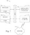
- FIG. 7shows a diagrammatic representation of a machine in the example form of a computing system 700 within which a set of instructions when executed and/or processing logic when activated may cause the machine to perform any one or more of the methodologies described and/or claimed herein.
- the machineoperates as a standalone device or may be connected (e.g., networked) to other machines.
- the machinemay operate in the capacity of a server or a client machine in server-client network environment, or as a peer machine in a peer-to-peer (or distributed) network environment.
- the machinemay be a personal computer (PC), a laptop computer, a tablet computing system, a Personal Digital Assistant (PDA), a cellular telephone, a smartphone, a web appliance, a set-top box (STB), a network router, switch or bridge, or any machine capable of executing a set of instructions (sequential or otherwise) or activating processing logic that specify actions to be taken by that machine.
- PCpersonal computer
- PDAPersonal Digital Assistant
- STBset-top box
- STBset-top box
- network routerswitch or bridge
- the example computing system 700can include a data processor 702 (e.g., a System-on-a-Chip (SoC), general processing core, graphics core, and optionally other processing logic) and a memory 704 , which can communicate with each other via a bus or other data transfer system 706 .
- the mobile computing and/or communication system 700may further include various input/output (I/O) devices and/or interfaces 710 , such as a touchscreen display, an audio jack, a voice interface, and optionally a network interface 712 .
- I/Oinput/output
- the network interface 712can include one or more radio transceivers configured for compatibility with any one or more standard wireless and/or cellular protocols or access technologies (e.g., 2nd (2G), 2.5, 3rd (3G), 4th (4G) generation, and future generation radio access for cellular systems, Global System for Mobile communication (GSM), General Packet Radio Services (GPRS), Enhanced Data GSM Environment (EDGE), Wideband Code Division Multiple Access (WCDMA), LTE, CDMA2000, WLAN, Wireless Router (WR) mesh, and the like).
- GSMGlobal System for Mobile communication
- GPRSGeneral Packet Radio Services
- EDGEEnhanced Data GSM Environment
- WCDMAWideband Code Division Multiple Access
- LTELong Term Evolution
- CDMA2000Code Division Multiple Access 2000
- WLANWireless Router
- Network interface 712may also be configured for use with various other wired and/or wireless communication protocols, including TCP/IP, UDP, SIP, SMS, RTP, WAP, CDMA, TDMA, UMTS, UWB, WiFi, WiMax, BluetoothTM, IEEE 802.11x, and the like.
- network interface 712may include or support virtually any wired and/or wireless communication and data processing mechanisms by which information/data may travel between a computing system 700 and another computing or communication system via network 714 .
- the memory 704can represent a machine-readable medium on which is stored one or more sets of instructions, software, firmware, or other processing logic (e.g., logic 708 ) embodying any one or more of the methodologies or functions described and/or claimed herein.
- the logic 708may also reside, completely or at least partially within the processor 702 during execution thereof by the mobile computing and/or communication system 700 .
- the memory 704 and the processor 702may also constitute machine-readable media.
- the logic 708 , or a portion thereofmay also be configured as processing logic or logic, at least a portion of which is partially implemented in hardware.
- the logic 708 , or a portion thereofmay further be transmitted or received over a network 714 via the network interface 712 .
- machine-readable medium of an example embodimentcan be a single medium
- the term “machine-readable medium”should be taken to include a single non-transitory medium or multiple non-transitory media (e.g., a centralized or distributed database, and/or associated caches and computing systems) that store the one or more sets of instructions.
- the term “machine-readable medium”can also be taken to include any non-transitory medium that is capable of storing, encoding or carrying a set of instructions for execution by the machine and that cause the machine to perform any one or more of the methodologies of the various embodiments, or that is capable of storing, encoding or carrying data structures utilized by or associated with such a set of instructions.
- the term “machine-readable medium”can accordingly be taken to include, but not be limited to, solid-state memories, optical media, and magnetic media.
Landscapes
- Engineering & Computer Science (AREA)
- Automation & Control Theory (AREA)
- Transportation (AREA)
- Mechanical Engineering (AREA)
- Human Computer Interaction (AREA)
- Traffic Control Systems (AREA)
- Control Of Driving Devices And Active Controlling Of Vehicle (AREA)
Abstract
Description
Vcmd=Vlead+W1(dactual−ddesired)+W2(vlead−Vfollowing)
Where:
Claims (20)
Priority Applications (5)
| Application Number | Priority Date | Filing Date | Title |
|---|---|---|---|
| US15/640,516US10737695B2 (en) | 2017-07-01 | 2017-07-01 | System and method for adaptive cruise control for low speed following |
| US15/806,127US10752246B2 (en) | 2017-07-01 | 2017-11-07 | System and method for adaptive cruise control with proximate vehicle detection |
| PCT/US2018/040484WO2019010099A1 (en) | 2017-07-01 | 2018-06-29 | SYSTEM AND METHOD FOR ADAPTIVE SPEED CONTROL FOR LOW SPEED TRACKING |
| US16/941,190US11753008B2 (en) | 2017-07-01 | 2020-07-28 | System and method for adaptive cruise control with proximate vehicle detection |
| US18/228,574US20230373483A1 (en) | 2017-07-01 | 2023-07-31 | System and method for adaptive cruise control with proximate vehicle detection |
Applications Claiming Priority (1)
| Application Number | Priority Date | Filing Date | Title |
|---|---|---|---|
| US15/640,516US10737695B2 (en) | 2017-07-01 | 2017-07-01 | System and method for adaptive cruise control for low speed following |
Related Child Applications (1)
| Application Number | Title | Priority Date | Filing Date |
|---|---|---|---|
| US15/806,127Continuation-In-PartUS10752246B2 (en) | 2017-07-01 | 2017-11-07 | System and method for adaptive cruise control with proximate vehicle detection |
Publications (2)
| Publication Number | Publication Date |
|---|---|
| US20190001976A1 US20190001976A1 (en) | 2019-01-03 |
| US10737695B2true US10737695B2 (en) | 2020-08-11 |
Family
ID=64735255
Family Applications (1)
| Application Number | Title | Priority Date | Filing Date |
|---|---|---|---|
| US15/640,516ActiveUS10737695B2 (en) | 2017-07-01 | 2017-07-01 | System and method for adaptive cruise control for low speed following |
Country Status (2)
| Country | Link |
|---|---|
| US (1) | US10737695B2 (en) |
| WO (1) | WO2019010099A1 (en) |
Cited By (2)
| Publication number | Priority date | Publication date | Assignee | Title |
|---|---|---|---|---|
| US11094199B2 (en)* | 2019-11-20 | 2021-08-17 | Hyundai Motor Company | Apparatus for displaying steering information of preceding vehicle and method thereof |
| US12403908B2 (en) | 2022-03-14 | 2025-09-02 | Garrett Transportation I Inc. | Non-selfish traffic lights passing advisory systems |
Families Citing this family (13)
| Publication number | Priority date | Publication date | Assignee | Title |
|---|---|---|---|---|
| US10552691B2 (en)* | 2017-04-25 | 2020-02-04 | TuSimple | System and method for vehicle position and velocity estimation based on camera and lidar data |
| US11758111B2 (en)* | 2017-10-27 | 2023-09-12 | Baidu Usa Llc | 3D lidar system using a dichroic mirror for autonomous driving vehicles |
| JP6580108B2 (en)* | 2017-11-06 | 2019-09-25 | 本田技研工業株式会社 | Driving control device for autonomous driving vehicle |
| US10909866B2 (en)* | 2018-07-20 | 2021-02-02 | Cybernet Systems Corp. | Autonomous transportation system and methods |
| FR3092304B1 (en)* | 2019-01-31 | 2021-01-01 | Psa Automobiles Sa | Management via an equivalent speed of autonomous driving with at least two target objects |
| US11618502B2 (en)* | 2019-03-28 | 2023-04-04 | Volkswagen Aktiengesellschaft | On-road localization methodologies and equipment utilizing road surface characteristics |
| CN110737271B (en)* | 2019-10-23 | 2022-08-02 | 西南科技大学 | Autonomous cruising system and method for water surface robot |
| CN111086512B (en)* | 2019-12-31 | 2021-06-04 | 浙江合众新能源汽车有限公司 | A method and device for enabling car ACC function by passive voice |
| GB2598965B (en)* | 2020-09-22 | 2022-10-26 | Jaguar Land Rover Ltd | Control of vehicle-to-vehicle separation |
| FR3118212B1 (en)* | 2020-12-17 | 2022-11-04 | Renault Sas | Supervision method for controlling an autonomous motor vehicle |
| EP4494962A3 (en)* | 2021-09-28 | 2025-05-07 | Robert Bosch GmbH | Controller and control method |
| CN114755998B (en)* | 2022-01-17 | 2025-08-05 | 深圳市星卡科技股份有限公司 | Adaptive cruise system remote dynamic calibration method, device and computer equipment |
| CN117465436B (en)* | 2023-11-29 | 2025-03-18 | 上海迅猛龙汽车电子有限公司 | Vehicle cruise control method and system |
Citations (108)
| Publication number | Priority date | Publication date | Assignee | Title |
|---|---|---|---|---|
| US6370475B1 (en)* | 1997-10-22 | 2002-04-09 | Intelligent Technologies International Inc. | Accident avoidance system |
| US20020055813A1 (en) | 1998-08-26 | 2002-05-09 | Nissan Motor Co., Ltd. | Automatic vehicular velocity control apparatus for automotive vehicle |
| US20030191568A1 (en)* | 2002-04-09 | 2003-10-09 | Breed David S. | Method and system for controlling a vehicle |
| US6777904B1 (en) | 2003-02-25 | 2004-08-17 | Ford Global Technologies, Llc | Method and system for controlling a motor |
| WO2005098739A1 (en) | 2004-04-08 | 2005-10-20 | Mobileye Technologies Limited | Pedestrian detection |
| WO2005098782A1 (en) | 2004-04-08 | 2005-10-20 | Mobileye Technologies Limited | Collision warning system |
| WO2005098751A1 (en) | 2004-04-08 | 2005-10-20 | Mobileye Technologies Limited | Crowd detection |
| US20060149455A1 (en) | 2005-01-06 | 2006-07-06 | Fuji Jukogyo Kabushiki Kaisha | Vehicle driving support apparatus |
| US7103460B1 (en) | 1994-05-09 | 2006-09-05 | Automotive Technologies International, Inc. | System and method for vehicle diagnostics |
| US20070255480A1 (en)* | 2006-04-21 | 2007-11-01 | Southall John B | Apparatus and method for object detection and tracking and roadway awareness using stereo cameras |
| US20080249667A1 (en) | 2007-04-09 | 2008-10-09 | Microsoft Corporation | Learning and reasoning to enhance energy efficiency in transportation systems |
| US20090040054A1 (en) | 2007-04-11 | 2009-02-12 | Nec Laboratories America, Inc. | Real-time driving danger level prediction |
| US20090132142A1 (en)* | 2005-10-07 | 2009-05-21 | Eaton Corporation | Adaptive cruise control for heavy-duty vehicles |
| US20100049397A1 (en) | 2008-08-22 | 2010-02-25 | Garmin Ltd. | Fuel efficient routing |
| US7689559B2 (en) | 2006-02-08 | 2010-03-30 | Telenor Asa | Document similarity scoring and ranking method, device and computer program product |
| US20100209881A1 (en)* | 2009-02-18 | 2010-08-19 | Gm Global Technology Operations, Inc. | Driving skill recognition based on behavioral diagnosis |
| US7783403B2 (en) | 1994-05-23 | 2010-08-24 | Automotive Technologies International, Inc. | System and method for preventing vehicular accidents |
| US20100226564A1 (en) | 2009-03-09 | 2010-09-09 | Xerox Corporation | Framework for image thumbnailing based on visual similarity |
| WO2010109419A1 (en) | 2009-03-26 | 2010-09-30 | Koninklijke Philips Electronics N.V. | Method and apparatus for modifying an image by using a saliency map based on color frequency |
| US20100281361A1 (en) | 2009-04-30 | 2010-11-04 | Xerox Corporation | Automated method for alignment of document objects |
| US20110206282A1 (en) | 2010-02-25 | 2011-08-25 | Kazuki Aisaka | Device, Method, and Program for Image Processing |
| US8041111B1 (en) | 2007-10-15 | 2011-10-18 | Adobe Systems Incorporated | Subjective and locatable color theme extraction for images |
| US20110282559A1 (en) | 2010-05-13 | 2011-11-17 | Denso Corporation | Vehicle-use speed control apparatus |
| US8064643B2 (en) | 2006-12-06 | 2011-11-22 | Mobileye Technologies Limited | Detecting and recognizing traffic signs |
| US8164628B2 (en) | 2006-01-04 | 2012-04-24 | Mobileye Technologies Ltd. | Estimating distance to an object using a sequence of images recorded by a monocular camera |
| EP2448251A2 (en) | 2010-10-31 | 2012-05-02 | Mobileye Technologies Limited | Bundling night vision and other driver assistance systems (DAS) using near infra red (NIR) illumination and a rolling shutter |
| US20120140076A1 (en) | 2010-12-07 | 2012-06-07 | Rosenbaum Dan | Forward collision warning trap and pedestrian advanced warning system |
| US20120274629A1 (en) | 2011-04-28 | 2012-11-01 | Baek Heumeil | Stereoscopic image display and method of adjusting stereoscopic image thereof |
| US8378851B2 (en) | 2006-05-31 | 2013-02-19 | Mobileye Technologies Limited | Fusion of images in enhanced obstacle detection |
| US20130052614A1 (en)* | 2011-08-31 | 2013-02-28 | Pulsar Informatics, Inc. | Driver Performance Metric |
| US8392117B2 (en) | 2009-05-22 | 2013-03-05 | Toyota Motor Engineering & Manufacturing North America, Inc. | Using topological structure for path planning in semi-structured environments |
| US8401292B2 (en) | 2011-04-26 | 2013-03-19 | Eastman Kodak Company | Identifying high saliency regions in digital images |
| US8412449B2 (en) | 2008-10-24 | 2013-04-02 | Gray & Company, Inc. | Control and systems for autonomously driven vehicles |
| WO2013045612A1 (en) | 2011-09-29 | 2013-04-04 | Aktiebolaget Skf | Device and method for detecting a distance value |
| US8553088B2 (en) | 2005-11-23 | 2013-10-08 | Mobileye Technologies Limited | Systems and methods for detecting obstructions in a camera field of view |
| US20140005908A1 (en)* | 2010-12-29 | 2014-01-02 | Volvo Lastvagnar Ab | Adaptative cruise control |
| WO2014011814A1 (en) | 2012-07-10 | 2014-01-16 | Thetis Pharmaceuticals Llc | Tri-salt form of metformin |
| US20140136073A1 (en)* | 2011-06-24 | 2014-05-15 | Renault S.A.S | Management of speed regulation of a vehicle |
| US20140145516A1 (en) | 2011-07-28 | 2014-05-29 | Honda Motor Co., Ltd. | Wireless power transmission method |
| US20140198184A1 (en) | 2013-01-15 | 2014-07-17 | Mobileye Technologies Ltd. | Stereo assist with rolling shutters |
| US8788134B1 (en) | 2013-01-04 | 2014-07-22 | GM Global Technology Operations LLC | Autonomous driving merge management system |
| WO2014201324A1 (en) | 2013-06-13 | 2014-12-18 | Gideon Stein | Vision augmented navigation |
| US8917169B2 (en) | 1993-02-26 | 2014-12-23 | Magna Electronics Inc. | Vehicular vision system |
| US8965621B1 (en) | 2010-10-05 | 2015-02-24 | Google Inc. | Driving pattern recognition and safety control |
| WO2015034417A1 (en) | 2013-09-09 | 2015-03-12 | Scania Cv Ab | Method and system for adaptive cruise control and vehicle |
| US20150081189A1 (en) | 2012-03-22 | 2015-03-19 | Jaguar Land Rover Limited | Method of Adaptive Cruise Control, Adaptive Cruise Control System and Vehicle Incorporating Such a System |
| US8993951B2 (en) | 1996-03-25 | 2015-03-31 | Magna Electronics Inc. | Driver assistance system for a vehicle |
| US9002632B1 (en) | 2009-07-19 | 2015-04-07 | Aaron T. Emigh | Fuel cost optimized routing |
| US9008369B2 (en) | 2004-04-15 | 2015-04-14 | Magna Electronics Inc. | Vision system for vehicle |
| US9025880B2 (en) | 2012-08-29 | 2015-05-05 | Disney Enterprises, Inc. | Visual saliency estimation for images and video |
| US9042648B2 (en) | 2012-02-23 | 2015-05-26 | Microsoft Technology Licensing, Llc | Salient object segmentation |
| WO2015083009A1 (en) | 2013-12-04 | 2015-06-11 | Mobileye Vision Technologies Ltd. | Systems and methods for mimicking a leading vehicle |
| WO2015103159A1 (en) | 2013-12-30 | 2015-07-09 | Tieman Craig Arnold | Connected vehicle system with infotainment interface for mobile devices |
| US9111444B2 (en) | 2012-10-31 | 2015-08-18 | Raytheon Company | Video and lidar target detection and tracking system and method for segmenting moving targets |
| US9117133B2 (en) | 2008-06-18 | 2015-08-25 | Spectral Image, Inc. | Systems and methods for hyperspectral imaging |
| US9118816B2 (en) | 2011-12-06 | 2015-08-25 | Mobileye Vision Technologies Ltd. | Road vertical contour detection |
| WO2015125022A2 (en) | 2014-02-20 | 2015-08-27 | Mobileye Vision Technologies Ltd. | Navigation based on radar-cued visual imaging |
| US9120485B1 (en) | 2012-09-14 | 2015-09-01 | Google Inc. | Methods and systems for smooth trajectory generation for a self-driving vehicle |
| US9122954B2 (en) | 2013-10-01 | 2015-09-01 | Mobileye Vision Technologies Ltd. | Performing a histogram using an array of addressable registers |
| US9134402B2 (en) | 2012-08-13 | 2015-09-15 | Digital Signal Corporation | System and method for calibrating video and lidar subsystems |
| US9147255B1 (en) | 2013-03-14 | 2015-09-29 | Hrl Laboratories, Llc | Rapid object detection by combining structural information from image segmentation with bio-inspired attentional mechanisms |
| US9176006B2 (en) | 2008-01-15 | 2015-11-03 | Mobileye Vision Technologies Ltd. | Detection and classification of light sources using a diffraction grating |
| US9183447B1 (en) | 2011-06-09 | 2015-11-10 | Mobileye Vision Technologies Ltd. | Object detection using candidate object alignment |
| US20150353082A1 (en) | 2014-06-05 | 2015-12-10 | Carnegie Mellon University | Unified motion planning algorithm for autonomous driving vehicle in obstacle avoidance maneuver |
| WO2015186002A2 (en) | 2014-06-03 | 2015-12-10 | Mobileye Vision Technologies Ltd. | Systems and methods for detecting an object |
| US9233688B2 (en) | 2014-01-30 | 2016-01-12 | Mobileye Vision Technologies Ltd. | Systems and methods for lane end recognition |
| US9233659B2 (en) | 2011-04-27 | 2016-01-12 | Mobileye Vision Technologies Ltd. | Pedestrian collision warning system |
| US9248835B2 (en) | 2014-03-20 | 2016-02-02 | Bayerische Motoren Werke Aktiengesellschaft | Method and device for establishing a trajectory for a vehicle |
| US9277132B2 (en) | 2013-02-21 | 2016-03-01 | Mobileye Vision Technologies Ltd. | Image distortion correction of a camera with a rolling shutter |
| US9280711B2 (en) | 2010-09-21 | 2016-03-08 | Mobileye Vision Technologies Ltd. | Barrier and guardrail detection using a single camera |
| US9299004B2 (en) | 2013-10-24 | 2016-03-29 | Adobe Systems Incorporated | Image foreground detection |
| US9297641B2 (en) | 2011-12-12 | 2016-03-29 | Mobileye Vision Technologies Ltd. | Detection of obstacles at night by analysis of shadows |
| US20160094774A1 (en) | 2014-09-29 | 2016-03-31 | Yahoo! Inc. | Mobile device image acquisition using objects of interest recognition |
| US9315192B1 (en) | 2013-09-30 | 2016-04-19 | Google Inc. | Methods and systems for pedestrian avoidance using LIDAR |
| US9317776B1 (en) | 2013-03-13 | 2016-04-19 | Hrl Laboratories, Llc | Robust static and moving object detection system via attentional mechanisms |
| US9317033B2 (en) | 2011-12-16 | 2016-04-19 | Renault S.A.S. | Control of the autonomous mode of bimodal vehicles |
| US20160107682A1 (en)* | 2014-10-15 | 2016-04-21 | Han-Shue Tan | System and method for vehicle steering control |
| US9330334B2 (en) | 2013-10-24 | 2016-05-03 | Adobe Systems Incorporated | Iterative saliency map estimation |
| US20160129907A1 (en) | 2014-11-12 | 2016-05-12 | Hyundai Motor Company | Driving path planning apparatus and method for autonomous vehicle |
| US9342074B2 (en) | 2013-04-05 | 2016-05-17 | Google Inc. | Systems and methods for transitioning control of an autonomous vehicle to a driver |
| US9355635B2 (en) | 2010-11-15 | 2016-05-31 | Futurewei Technologies, Inc. | Method and system for video summarization |
| US20160210528A1 (en) | 2014-02-24 | 2016-07-21 | Beijing University Of Technology | Method for detecting visual saliencies of video image based on spatial and temporal features |
| US9399397B2 (en) | 2012-02-13 | 2016-07-26 | Denso Corporation | Cruise control apparatus |
| WO2016135736A2 (en) | 2015-02-26 | 2016-09-01 | Mobileye Vision Technologies Ltd. | Road vertical contour detection using a stabilized coordinate frame |
| US9438878B2 (en) | 2013-05-01 | 2016-09-06 | Legend3D, Inc. | Method of converting 2D video to 3D video using 3D object models |
| US9436880B2 (en) | 1999-08-12 | 2016-09-06 | Magna Electronics Inc. | Vehicle vision system |
| US9443163B2 (en) | 2014-05-14 | 2016-09-13 | Mobileye Vision Technologies Ltd. | Systems and methods for curb detection and pedestrian hazard assessment |
| US9459515B2 (en) | 2008-12-05 | 2016-10-04 | Mobileye Vision Technologies Ltd. | Adjustable camera mount for a vehicle windshield |
| EP3081419A1 (en) | 2015-04-17 | 2016-10-19 | Iseki & Co., Ltd. | Working vehicle |
| US9476970B1 (en) | 2012-03-19 | 2016-10-25 | Google Inc. | Camera based localization |
| US20160321381A1 (en) | 2015-04-29 | 2016-11-03 | Energid Technologies Corporation | System and method for evaluation of object autonomy |
| US20160375907A1 (en) | 2015-06-26 | 2016-12-29 | Robert Bosch Gmbh | Method and device for ascertaining or evaluating a setpoint trajectory of a motor vehicle |
| US9535423B1 (en) | 2016-03-29 | 2017-01-03 | Adasworks Kft. | Autonomous vehicle with improved visual detection ability |
| WO2017013875A1 (en) | 2015-07-23 | 2017-01-26 | 日本電気株式会社 | Route switching device, route switching system, and route switching method |
| US9555803B2 (en) | 2002-05-03 | 2017-01-31 | Magna Electronics Inc. | Driver assistance system for vehicle |
| US9568915B1 (en) | 2016-02-11 | 2017-02-14 | Mitsubishi Electric Research Laboratories, Inc. | System and method for controlling autonomous or semi-autonomous vehicle |
| US9587952B1 (en) | 2015-09-09 | 2017-03-07 | Allstate Insurance Company | Altering autonomous or semi-autonomous vehicle operation based on route traversal values |
| US9720418B2 (en) | 2014-05-27 | 2017-08-01 | Here Global B.V. | Autonomous vehicle monitoring and control |
| US9723099B2 (en) | 2014-04-28 | 2017-08-01 | Cisco Technology, Inc. | Screen sharing cache management |
| US9723097B2 (en) | 2013-01-02 | 2017-08-01 | International Business Machines Corporation | Assigning shared catalogs to cache structures in a cluster computing system |
| US9738280B2 (en) | 2013-10-03 | 2017-08-22 | Robert Bosch Gmbh | Adaptive cruise control with on-ramp detection |
| US9746550B2 (en) | 2014-10-08 | 2017-08-29 | Ford Global Technologies, Llc | Detecting low-speed close-range vehicle cut-in |
| US20170369062A1 (en)* | 2016-06-23 | 2017-12-28 | Honda Motor Co., Ltd. | System and method for vehicle control using vehicular communication |
| US20170369067A1 (en)* | 2016-06-23 | 2017-12-28 | Honda Motor Co., Ltd. | System and method for merge assist using vehicular communication |
| US20180037227A1 (en)* | 2016-06-23 | 2018-02-08 | Honda Motor Co., Ltd. | System and method for vehicle control in tailgating situations |
| US20180197299A1 (en)* | 2017-01-11 | 2018-07-12 | Kabushiki Kaisha Toshiba | Information processing device, information processing method, and computer program product |
| US20180308250A1 (en)* | 2017-04-25 | 2018-10-25 | TuSimple | System and method for vehicle position and velocity estimation based on camera and lidar data |
| US20180365835A1 (en)* | 2017-06-14 | 2018-12-20 | TuSimple | System and method for actively selecting and labeling images for semantic segmentation |
- 2017
- 2017-07-01USUS15/640,516patent/US10737695B2/enactiveActive
- 2018
- 2018-06-29WOPCT/US2018/040484patent/WO2019010099A1/ennot_activeCeased
Patent Citations (146)
| Publication number | Priority date | Publication date | Assignee | Title |
|---|---|---|---|---|
| US8917169B2 (en) | 1993-02-26 | 2014-12-23 | Magna Electronics Inc. | Vehicular vision system |
| US7103460B1 (en) | 1994-05-09 | 2006-09-05 | Automotive Technologies International, Inc. | System and method for vehicle diagnostics |
| US7783403B2 (en) | 1994-05-23 | 2010-08-24 | Automotive Technologies International, Inc. | System and method for preventing vehicular accidents |
| US8993951B2 (en) | 1996-03-25 | 2015-03-31 | Magna Electronics Inc. | Driver assistance system for a vehicle |
| US6370475B1 (en)* | 1997-10-22 | 2002-04-09 | Intelligent Technologies International Inc. | Accident avoidance system |
| US20020055813A1 (en) | 1998-08-26 | 2002-05-09 | Nissan Motor Co., Ltd. | Automatic vehicular velocity control apparatus for automotive vehicle |
| US9436880B2 (en) | 1999-08-12 | 2016-09-06 | Magna Electronics Inc. | Vehicle vision system |
| US20030191568A1 (en)* | 2002-04-09 | 2003-10-09 | Breed David S. | Method and system for controlling a vehicle |
| US9555803B2 (en) | 2002-05-03 | 2017-01-31 | Magna Electronics Inc. | Driver assistance system for vehicle |
| US6777904B1 (en) | 2003-02-25 | 2004-08-17 | Ford Global Technologies, Llc | Method and system for controlling a motor |
| WO2005098782A1 (en) | 2004-04-08 | 2005-10-20 | Mobileye Technologies Limited | Collision warning system |
| US20070230792A1 (en) | 2004-04-08 | 2007-10-04 | Mobileye Technologies Ltd. | Pedestrian Detection |
| EP1754179A1 (en) | 2004-04-08 | 2007-02-21 | Mobileye Technologies Limited | Pedestrian detection |
| WO2005098751A1 (en) | 2004-04-08 | 2005-10-20 | Mobileye Technologies Limited | Crowd detection |
| US8082101B2 (en) | 2004-04-08 | 2011-12-20 | Mobileye Technologies Ltd. | Collision warning system |
| WO2005098739A1 (en) | 2004-04-08 | 2005-10-20 | Mobileye Technologies Limited | Pedestrian detection |
| US9428192B2 (en) | 2004-04-15 | 2016-08-30 | Magna Electronics Inc. | Vision system for vehicle |
| US9008369B2 (en) | 2004-04-15 | 2015-04-14 | Magna Electronics Inc. | Vision system for vehicle |
| US9191634B2 (en) | 2004-04-15 | 2015-11-17 | Magna Electronics Inc. | Vision system for vehicle |
| US20060149455A1 (en) | 2005-01-06 | 2006-07-06 | Fuji Jukogyo Kabushiki Kaisha | Vehicle driving support apparatus |
| US20090132142A1 (en)* | 2005-10-07 | 2009-05-21 | Eaton Corporation | Adaptive cruise control for heavy-duty vehicles |
| US8553088B2 (en) | 2005-11-23 | 2013-10-08 | Mobileye Technologies Limited | Systems and methods for detecting obstructions in a camera field of view |
| US9185360B2 (en) | 2005-11-23 | 2015-11-10 | Mobileye Vision Technologies Ltd. | Systems and methods for detecting obstructions in a camera field of view |
| US8164628B2 (en) | 2006-01-04 | 2012-04-24 | Mobileye Technologies Ltd. | Estimating distance to an object using a sequence of images recorded by a monocular camera |
| US7844595B2 (en) | 2006-02-08 | 2010-11-30 | Telenor Asa | Document similarity scoring and ranking method, device and computer program product |
| US7689559B2 (en) | 2006-02-08 | 2010-03-30 | Telenor Asa | Document similarity scoring and ranking method, device and computer program product |
| US20070255480A1 (en)* | 2006-04-21 | 2007-11-01 | Southall John B | Apparatus and method for object detection and tracking and roadway awareness using stereo cameras |
| US8981966B2 (en) | 2006-05-31 | 2015-03-17 | Mobileye Vision Technologies Ltd. | Fusion of far infrared and visible images in enhanced obstacle detection in automotive applications |
| US8378851B2 (en) | 2006-05-31 | 2013-02-19 | Mobileye Technologies Limited | Fusion of images in enhanced obstacle detection |
| US8064643B2 (en) | 2006-12-06 | 2011-11-22 | Mobileye Technologies Limited | Detecting and recognizing traffic signs |
| US20080249667A1 (en) | 2007-04-09 | 2008-10-09 | Microsoft Corporation | Learning and reasoning to enhance energy efficiency in transportation systems |
| US20090040054A1 (en) | 2007-04-11 | 2009-02-12 | Nec Laboratories America, Inc. | Real-time driving danger level prediction |
| US8041111B1 (en) | 2007-10-15 | 2011-10-18 | Adobe Systems Incorporated | Subjective and locatable color theme extraction for images |
| US9176006B2 (en) | 2008-01-15 | 2015-11-03 | Mobileye Vision Technologies Ltd. | Detection and classification of light sources using a diffraction grating |
| US9117133B2 (en) | 2008-06-18 | 2015-08-25 | Spectral Image, Inc. | Systems and methods for hyperspectral imaging |
| US20100049397A1 (en) | 2008-08-22 | 2010-02-25 | Garmin Ltd. | Fuel efficient routing |
| US8412449B2 (en) | 2008-10-24 | 2013-04-02 | Gray & Company, Inc. | Control and systems for autonomously driven vehicles |
| US9459515B2 (en) | 2008-12-05 | 2016-10-04 | Mobileye Vision Technologies Ltd. | Adjustable camera mount for a vehicle windshield |
| US20100209881A1 (en)* | 2009-02-18 | 2010-08-19 | Gm Global Technology Operations, Inc. | Driving skill recognition based on behavioral diagnosis |
| US20100226564A1 (en) | 2009-03-09 | 2010-09-09 | Xerox Corporation | Framework for image thumbnailing based on visual similarity |
| US8175376B2 (en) | 2009-03-09 | 2012-05-08 | Xerox Corporation | Framework for image thumbnailing based on visual similarity |
| WO2010109419A1 (en) | 2009-03-26 | 2010-09-30 | Koninklijke Philips Electronics N.V. | Method and apparatus for modifying an image by using a saliency map based on color frequency |
| US8271871B2 (en) | 2009-04-30 | 2012-09-18 | Xerox Corporation | Automated method for alignment of document objects |
| US20100281361A1 (en) | 2009-04-30 | 2010-11-04 | Xerox Corporation | Automated method for alignment of document objects |
| US8392117B2 (en) | 2009-05-22 | 2013-03-05 | Toyota Motor Engineering & Manufacturing North America, Inc. | Using topological structure for path planning in semi-structured environments |
| US9002632B1 (en) | 2009-07-19 | 2015-04-07 | Aaron T. Emigh | Fuel cost optimized routing |
| US20110206282A1 (en) | 2010-02-25 | 2011-08-25 | Kazuki Aisaka | Device, Method, and Program for Image Processing |
| US8478072B2 (en) | 2010-02-25 | 2013-07-02 | Sony Corporation | Device, method, and program for image processing |
| US20110282559A1 (en) | 2010-05-13 | 2011-11-17 | Denso Corporation | Vehicle-use speed control apparatus |
| US9280711B2 (en) | 2010-09-21 | 2016-03-08 | Mobileye Vision Technologies Ltd. | Barrier and guardrail detection using a single camera |
| US8965621B1 (en) | 2010-10-05 | 2015-02-24 | Google Inc. | Driving pattern recognition and safety control |
| US9179072B2 (en) | 2010-10-31 | 2015-11-03 | Mobileye Vision Technologies Ltd. | Bundling night vision and other driver assistance systems (DAS) using near infra red (NIR) illumination and a rolling shutter |
| US20160037064A1 (en) | 2010-10-31 | 2016-02-04 | Mobileye Vision Technologies Ltd. | Bundling night vision and other driver assistance systems (das) using near infra red (nir) illumination and a rolling shutter |
| EP2448251A3 (en) | 2010-10-31 | 2015-10-28 | Mobileye Vision Technologies Ltd. | Bundling night vision and other driver assistance systems (DAS) using near infra red (NIR) illumination and a rolling shutter |
| EP2448251A2 (en) | 2010-10-31 | 2012-05-02 | Mobileye Technologies Limited | Bundling night vision and other driver assistance systems (DAS) using near infra red (NIR) illumination and a rolling shutter |
| US20120105639A1 (en) | 2010-10-31 | 2012-05-03 | Mobileye Technologies Ltd. | Bundling night vision and other driver assistance systems (das) using near infra red (nir) illumination and a rolling shutter |
| US9355635B2 (en) | 2010-11-15 | 2016-05-31 | Futurewei Technologies, Inc. | Method and system for video summarization |
| EP2463843B1 (en) | 2010-12-07 | 2015-07-29 | Mobileye Vision Technologies Ltd. | Method and system for forward collision warning |
| EP2993654A1 (en) | 2010-12-07 | 2016-03-09 | Mobileye Vision Technologies Ltd. | Method and system for forward collision warning |
| US20120140076A1 (en) | 2010-12-07 | 2012-06-07 | Rosenbaum Dan | Forward collision warning trap and pedestrian advanced warning system |
| EP2463843A2 (en) | 2010-12-07 | 2012-06-13 | Mobileye Technologies Limited | Method and system for forward collision warning |
| US9251708B2 (en) | 2010-12-07 | 2016-02-02 | Mobileye Vision Technologies Ltd. | Forward collision warning trap and pedestrian advanced warning system |
| US20140005908A1 (en)* | 2010-12-29 | 2014-01-02 | Volvo Lastvagnar Ab | Adaptative cruise control |
| US8401292B2 (en) | 2011-04-26 | 2013-03-19 | Eastman Kodak Company | Identifying high saliency regions in digital images |
| US9233659B2 (en) | 2011-04-27 | 2016-01-12 | Mobileye Vision Technologies Ltd. | Pedestrian collision warning system |
| US20120274629A1 (en) | 2011-04-28 | 2012-11-01 | Baek Heumeil | Stereoscopic image display and method of adjusting stereoscopic image thereof |
| US8963913B2 (en) | 2011-04-28 | 2015-02-24 | Lg Display Co., Ltd. | Stereoscopic image display and method of adjusting stereoscopic image thereof |
| US9183447B1 (en) | 2011-06-09 | 2015-11-10 | Mobileye Vision Technologies Ltd. | Object detection using candidate object alignment |
| US20140136073A1 (en)* | 2011-06-24 | 2014-05-15 | Renault S.A.S | Management of speed regulation of a vehicle |
| US20140145516A1 (en) | 2011-07-28 | 2014-05-29 | Honda Motor Co., Ltd. | Wireless power transmission method |
| US9490064B2 (en) | 2011-07-28 | 2016-11-08 | Honda Motor Co., Ltd. | Wireless power transmission method |
| US20130052614A1 (en)* | 2011-08-31 | 2013-02-28 | Pulsar Informatics, Inc. | Driver Performance Metric |
| WO2013045612A1 (en) | 2011-09-29 | 2013-04-04 | Aktiebolaget Skf | Device and method for detecting a distance value |
| EP2761249A1 (en) | 2011-09-29 | 2014-08-06 | Aktiebolaget SKF (publ) | Device and method for detecting a distance value |
| US9118816B2 (en) | 2011-12-06 | 2015-08-25 | Mobileye Vision Technologies Ltd. | Road vertical contour detection |
| US9297641B2 (en) | 2011-12-12 | 2016-03-29 | Mobileye Vision Technologies Ltd. | Detection of obstacles at night by analysis of shadows |
| US9317033B2 (en) | 2011-12-16 | 2016-04-19 | Renault S.A.S. | Control of the autonomous mode of bimodal vehicles |
| US9399397B2 (en) | 2012-02-13 | 2016-07-26 | Denso Corporation | Cruise control apparatus |
| US9042648B2 (en) | 2012-02-23 | 2015-05-26 | Microsoft Technology Licensing, Llc | Salient object segmentation |
| US9476970B1 (en) | 2012-03-19 | 2016-10-25 | Google Inc. | Camera based localization |
| US20150081189A1 (en) | 2012-03-22 | 2015-03-19 | Jaguar Land Rover Limited | Method of Adaptive Cruise Control, Adaptive Cruise Control System and Vehicle Incorporating Such a System |
| WO2014011814A1 (en) | 2012-07-10 | 2014-01-16 | Thetis Pharmaceuticals Llc | Tri-salt form of metformin |
| US9134402B2 (en) | 2012-08-13 | 2015-09-15 | Digital Signal Corporation | System and method for calibrating video and lidar subsystems |
| US9025880B2 (en) | 2012-08-29 | 2015-05-05 | Disney Enterprises, Inc. | Visual saliency estimation for images and video |
| US9120485B1 (en) | 2012-09-14 | 2015-09-01 | Google Inc. | Methods and systems for smooth trajectory generation for a self-driving vehicle |
| US9111444B2 (en) | 2012-10-31 | 2015-08-18 | Raytheon Company | Video and lidar target detection and tracking system and method for segmenting moving targets |
| US9723097B2 (en) | 2013-01-02 | 2017-08-01 | International Business Machines Corporation | Assigning shared catalogs to cache structures in a cluster computing system |
| US8788134B1 (en) | 2013-01-04 | 2014-07-22 | GM Global Technology Operations LLC | Autonomous driving merge management system |
| US20150062304A1 (en) | 2013-01-15 | 2015-03-05 | Mobileye Vision Technologies Ltd. | Stereo assist with rolling shutters |
| US9286522B2 (en) | 2013-01-15 | 2016-03-15 | Mobileye Vision Technologies Ltd. | Stereo assist with rolling shutters |
| WO2014111814A2 (en) | 2013-01-15 | 2014-07-24 | Mobileye Technologies Limited | Stereo assist with rolling shutters |
| US8908041B2 (en) | 2013-01-15 | 2014-12-09 | Mobileye Vision Technologies Ltd. | Stereo assist with rolling shutters |
| EP2946336A2 (en) | 2013-01-15 | 2015-11-25 | Mobileye Vision Technologies Ltd. | Stereo assist with rolling shutters |
| US20140198184A1 (en) | 2013-01-15 | 2014-07-17 | Mobileye Technologies Ltd. | Stereo assist with rolling shutters |
| US20160165157A1 (en) | 2013-01-15 | 2016-06-09 | Mobileye Vision Technologies Ltd. | Stereo assist with rolling shutters |
| US9531966B2 (en) | 2013-01-15 | 2016-12-27 | Mobileye Vision Technologies Ltd. | Stereo assist with rolling shutters |
| WO2014111814A3 (en) | 2013-01-15 | 2015-02-19 | Mobileye Vision Technologies Ltd. | Stereo assist with rolling shutters |
| US9277132B2 (en) | 2013-02-21 | 2016-03-01 | Mobileye Vision Technologies Ltd. | Image distortion correction of a camera with a rolling shutter |
| US9317776B1 (en) | 2013-03-13 | 2016-04-19 | Hrl Laboratories, Llc | Robust static and moving object detection system via attentional mechanisms |
| US9147255B1 (en) | 2013-03-14 | 2015-09-29 | Hrl Laboratories, Llc | Rapid object detection by combining structural information from image segmentation with bio-inspired attentional mechanisms |
| US9342074B2 (en) | 2013-04-05 | 2016-05-17 | Google Inc. | Systems and methods for transitioning control of an autonomous vehicle to a driver |
| US9438878B2 (en) | 2013-05-01 | 2016-09-06 | Legend3D, Inc. | Method of converting 2D video to 3D video using 3D object models |
| WO2014201324A1 (en) | 2013-06-13 | 2014-12-18 | Gideon Stein | Vision augmented navigation |
| KR20160053984A (en) | 2013-09-09 | 2016-05-13 | 스카니아 씨브이 악티에볼라그 | Method and system for adaptive cruise control and vehicle |
| WO2015034417A1 (en) | 2013-09-09 | 2015-03-12 | Scania Cv Ab | Method and system for adaptive cruise control and vehicle |
| US9315192B1 (en) | 2013-09-30 | 2016-04-19 | Google Inc. | Methods and systems for pedestrian avoidance using LIDAR |
| US9122954B2 (en) | 2013-10-01 | 2015-09-01 | Mobileye Vision Technologies Ltd. | Performing a histogram using an array of addressable registers |
| US9738280B2 (en) | 2013-10-03 | 2017-08-22 | Robert Bosch Gmbh | Adaptive cruise control with on-ramp detection |
| US9299004B2 (en) | 2013-10-24 | 2016-03-29 | Adobe Systems Incorporated | Image foreground detection |
| US9330334B2 (en) | 2013-10-24 | 2016-05-03 | Adobe Systems Incorporated | Iterative saliency map estimation |
| WO2015083009A1 (en) | 2013-12-04 | 2015-06-11 | Mobileye Vision Technologies Ltd. | Systems and methods for mimicking a leading vehicle |
| US9156473B2 (en) | 2013-12-04 | 2015-10-13 | Mobileye Vision Technologies Ltd. | Multi-threshold reaction zone for autonomous vehicle navigation |
| US9145116B2 (en) | 2013-12-04 | 2015-09-29 | Mobileye Vision Technologies Ltd. | Systems and methods for implementing a multi-segment braking profile for a vehicle |
| WO2015103159A1 (en) | 2013-12-30 | 2015-07-09 | Tieman Craig Arnold | Connected vehicle system with infotainment interface for mobile devices |
| US9446765B2 (en) | 2014-01-30 | 2016-09-20 | Mobileye Vision Technologies Ltd. | Systems and methods for identifying relevant traffic lights |
| US9365214B2 (en) | 2014-01-30 | 2016-06-14 | Mobileye Vision Technologies Ltd. | Systems and methods for determining the status of a turn lane traffic light |
| US9248832B2 (en) | 2014-01-30 | 2016-02-02 | Mobileye Vision Technologies Ltd. | Systems and methods for detecting traffic signal details |
| US9233688B2 (en) | 2014-01-30 | 2016-01-12 | Mobileye Vision Technologies Ltd. | Systems and methods for lane end recognition |
| WO2015125022A2 (en) | 2014-02-20 | 2015-08-27 | Mobileye Vision Technologies Ltd. | Navigation based on radar-cued visual imaging |
| US20160210528A1 (en) | 2014-02-24 | 2016-07-21 | Beijing University Of Technology | Method for detecting visual saliencies of video image based on spatial and temporal features |
| US9466006B2 (en) | 2014-02-24 | 2016-10-11 | Beijing University Of Technology | Method for detecting visual saliencies of video image based on spatial and temporal features |
| US9248835B2 (en) | 2014-03-20 | 2016-02-02 | Bayerische Motoren Werke Aktiengesellschaft | Method and device for establishing a trajectory for a vehicle |
| US9723099B2 (en) | 2014-04-28 | 2017-08-01 | Cisco Technology, Inc. | Screen sharing cache management |
| US9443163B2 (en) | 2014-05-14 | 2016-09-13 | Mobileye Vision Technologies Ltd. | Systems and methods for curb detection and pedestrian hazard assessment |
| US9720418B2 (en) | 2014-05-27 | 2017-08-01 | Here Global B.V. | Autonomous vehicle monitoring and control |
| WO2015186002A2 (en) | 2014-06-03 | 2015-12-10 | Mobileye Vision Technologies Ltd. | Systems and methods for detecting an object |
| WO2015186002A3 (en) | 2014-06-03 | 2016-03-31 | Mobileye Vision Technologies Ltd. | Systems and methods for detecting an object |
| US20150353082A1 (en) | 2014-06-05 | 2015-12-10 | Carnegie Mellon University | Unified motion planning algorithm for autonomous driving vehicle in obstacle avoidance maneuver |
| US20160094774A1 (en) | 2014-09-29 | 2016-03-31 | Yahoo! Inc. | Mobile device image acquisition using objects of interest recognition |
| US9746550B2 (en) | 2014-10-08 | 2017-08-29 | Ford Global Technologies, Llc | Detecting low-speed close-range vehicle cut-in |
| US20160107682A1 (en)* | 2014-10-15 | 2016-04-21 | Han-Shue Tan | System and method for vehicle steering control |
| US20160129907A1 (en) | 2014-11-12 | 2016-05-12 | Hyundai Motor Company | Driving path planning apparatus and method for autonomous vehicle |
| WO2016135736A2 (en) | 2015-02-26 | 2016-09-01 | Mobileye Vision Technologies Ltd. | Road vertical contour detection using a stabilized coordinate frame |
| EP3081419A1 (en) | 2015-04-17 | 2016-10-19 | Iseki & Co., Ltd. | Working vehicle |
| US20160321381A1 (en) | 2015-04-29 | 2016-11-03 | Energid Technologies Corporation | System and method for evaluation of object autonomy |
| US20160375907A1 (en) | 2015-06-26 | 2016-12-29 | Robert Bosch Gmbh | Method and device for ascertaining or evaluating a setpoint trajectory of a motor vehicle |
| WO2017013875A1 (en) | 2015-07-23 | 2017-01-26 | 日本電気株式会社 | Route switching device, route switching system, and route switching method |
| US9587952B1 (en) | 2015-09-09 | 2017-03-07 | Allstate Insurance Company | Altering autonomous or semi-autonomous vehicle operation based on route traversal values |
| US9568915B1 (en) | 2016-02-11 | 2017-02-14 | Mitsubishi Electric Research Laboratories, Inc. | System and method for controlling autonomous or semi-autonomous vehicle |
| US9535423B1 (en) | 2016-03-29 | 2017-01-03 | Adasworks Kft. | Autonomous vehicle with improved visual detection ability |
| US20170369062A1 (en)* | 2016-06-23 | 2017-12-28 | Honda Motor Co., Ltd. | System and method for vehicle control using vehicular communication |
| US20170369067A1 (en)* | 2016-06-23 | 2017-12-28 | Honda Motor Co., Ltd. | System and method for merge assist using vehicular communication |
| US20180037227A1 (en)* | 2016-06-23 | 2018-02-08 | Honda Motor Co., Ltd. | System and method for vehicle control in tailgating situations |
| US20180197299A1 (en)* | 2017-01-11 | 2018-07-12 | Kabushiki Kaisha Toshiba | Information processing device, information processing method, and computer program product |
| US20180308250A1 (en)* | 2017-04-25 | 2018-10-25 | TuSimple | System and method for vehicle position and velocity estimation based on camera and lidar data |
| US20180365835A1 (en)* | 2017-06-14 | 2018-12-20 | TuSimple | System and method for actively selecting and labeling images for semantic segmentation |
Non-Patent Citations (17)
| Title |
|---|
| Badrinarayanan et al. "SegNet: A Deep Convolutional Encoder-Decoder Architecture for image Segmentation" Nov. 2, 2015 last accessed Jul. 20, 2019 online at https://arxiv.org/abs/1511.00561 (Year: 2015).* |
| C. Yang, Z. Li, R. Cui and B. Xu, "Neural Network-Based Motion Control of an Underactuated Wheeled Inverted Pendulum Model," in IEEE Transactions on Neural Networks and Learning Systems, vol. 25, No. 11, pp. 2004-2016, Nov. 2014. |
| Hou, Xiaodi and Harel, Jonathan and Koch, Christof, "Image Signature: Highlighting Sparse Salient Regions", IEEE Transactions on Pattern Analysis and Machine Intelligence, vol. 34, No. 1, pp. 194-201, 2012. |
| Hou, Xiaodi and Yuille, Alan and Koch, Christof, "Boundary Detection Benchmarking: Beyond F-Measures", Computer Vision and Pattern Recognition, CVPR'13, vol. 2013, pp. 1-8, IEEE, 2013. |
| Hou, Xiaodi and Zhang, Liqing, "A Time-Dependent Model of Information Capacity of Visual Attention", International Conference on Neural Information Processing, pp. 127-136, Springer Berlin Heidelberg, 2006. |
| Hou, Xiaodi and Zhang, Liqing, "Color Conceptualization", Proceedings of the 15th ACM International Conference on Multimedia, pp. 265-268, ACM, 2007. |
| Hou, Xiaodi and Zhang, Liqing, "Dynamic Visual Attention: Searching for Coding Length Increments", Advances in Neural Information Processing Systems, vol. 21, pp. 681-688, 2008. |
| Hou, Xiaodi and Zhang, Liqing, "Dynamic Visual Attention: Searching for Coding Length Increments", Advances in Veural Information Processing Systems, vol. 21, pp. 681-688, 2008. |
| Hou, Xiaodi and Zhang, Liqing, "Saliency Detection: A Spectral Residual Approach", Computer Vision and Pattern Recognition, CVPR'07—IEEE Conference, pp. 1-8, 2007. |
| Hou, Xiaodi and Zhang, Liqing, "Thumbnail Generation Based on Global Saliency", Advances in Cognitive Neurodynamics, ICCN 2007, pp. 999-1003, Springer Netherlands, 2008. |
| Li, Yin and Hou, Xiaodi and Koch, Christof and Rehg, James M. and Yuille, Alan L., "The Secrets of Salient Object Segmentation", Proceedings of the IEEE Conference on Computer Vision and Pattern Recognition, pp. 280-287, 2014. |
| Notification of Transmittal of the International Search Report and the Written Opinion of the International Searching Authority, or the Declaration, International application No. PCT/US2018/040484; International filing date: Jun. 29, 2018; dated Nov. 6, 2018. 2 pages. |
| P. Guarneri, G. Rocca and M. Gobbi, "A Neural-Network-Based Model for the Dynamic Simulation of the Tire/Suspension System While Traversing Road Irregularities," in IEEE Transactions on Neural Networks, vol. 19, No. 9, pp. 1549-1563, Sep. 2008. |
| PCT International Search Report, International application No. PCT/US2018/040484; International filing date: Jun. 29, 2018; dated Nov. 6, 2018. 3 pages. |
| Spinello, Luciano, Triebel, Rudolph, Siegwart, Roland, "Multiclass Multimodal Detection and Tracking in Urban Environments", Sage Journals, vol. 29 issue: 12, pp. 1498-1515 Article first published online: Oct. 7, 2010;Issue published: Oct. 1, 2010. |
| Written Opinion of the International Searching Authority, International application No. PCT/US2018/040484; International filing date: Jun. 29, 2018; dated Nov. 6, 2018. 6 pages. |
| Zhou, Bolei and Hou, Xiaodi and Zhang, Liqing, "A Phase Discrepancy Analysis of Object Motion", Asian Conference on Computer Vision, pp. 225-238, Springer Berlin Heidelberg, 2010. |
Cited By (2)
| Publication number | Priority date | Publication date | Assignee | Title |
|---|---|---|---|---|
| US11094199B2 (en)* | 2019-11-20 | 2021-08-17 | Hyundai Motor Company | Apparatus for displaying steering information of preceding vehicle and method thereof |
| US12403908B2 (en) | 2022-03-14 | 2025-09-02 | Garrett Transportation I Inc. | Non-selfish traffic lights passing advisory systems |
Also Published As
| Publication number | Publication date |
|---|---|
| WO2019010099A1 (en) | 2019-01-10 |
| US20190001976A1 (en) | 2019-01-03 |
Similar Documents
| Publication | Publication Date | Title |
|---|---|---|
| US11753008B2 (en) | System and method for adaptive cruise control with proximate vehicle detection | |
| US11928868B2 (en) | System and method for vehicle position and velocity estimation based on camera and LIDAR data | |
| US11673557B2 (en) | System and method for path planning of autonomous vehicles based on gradient | |
| US10737695B2 (en) | System and method for adaptive cruise control for low speed following | |
| US10953881B2 (en) | System and method for automated lane change control for autonomous vehicles | |
| US11958473B2 (en) | System and method for using human driving patterns to detect and correct abnormal driving behaviors of autonomous vehicles | |
| US10953880B2 (en) | System and method for automated lane change control for autonomous vehicles | |
| US10558864B2 (en) | System and method for image localization based on semantic segmentation | |
| AU2024202532A1 (en) | System and method for transitioning between an autonomous and manual driving mode based on detection of a driver's capacity to control a vehicle | |
| WO2020056431A1 (en) | System and method for three-dimensional (3d) object detection | |
| US11500387B2 (en) | System and method for providing multiple agents for decision making, trajectory planning, and control for autonomous vehicles | |
| US10493988B2 (en) | System and method for adaptive cruise control for defensive driving | |
| EP3758998A1 (en) | System and method for automated lane change control for autonomous vehicles |
Legal Events
| Date | Code | Title | Description |
|---|---|---|---|
| AS | Assignment | Owner name:TUSIMPLE, CALIFORNIA Free format text:ASSIGNMENT OF ASSIGNORS INTEREST;ASSIGNORS:LIN, WUTU;LIU, LIU;REEL/FRAME:047467/0749 Effective date:20170630 | |
| STPP | Information on status: patent application and granting procedure in general | Free format text:FINAL REJECTION MAILED | |
| STPP | Information on status: patent application and granting procedure in general | Free format text:DOCKETED NEW CASE - READY FOR EXAMINATION | |
| STPP | Information on status: patent application and granting procedure in general | Free format text:NON FINAL ACTION MAILED | |
| STPP | Information on status: patent application and granting procedure in general | Free format text:RESPONSE TO NON-FINAL OFFICE ACTION ENTERED AND FORWARDED TO EXAMINER | |
| STPP | Information on status: patent application and granting procedure in general | Free format text:FINAL REJECTION MAILED | |
| AS | Assignment | Owner name:TUSIMPLE, INC., CALIFORNIA Free format text:CHANGE OF NAME;ASSIGNOR:TUSIMPLE;REEL/FRAME:051757/0470 Effective date:20190412 | |
| STPP | Information on status: patent application and granting procedure in general | Free format text:NOTICE OF ALLOWANCE MAILED -- APPLICATION RECEIVED IN OFFICE OF PUBLICATIONS | |
| STPP | Information on status: patent application and granting procedure in general | Free format text:PUBLICATIONS -- ISSUE FEE PAYMENT RECEIVED | |
| STCF | Information on status: patent grant | Free format text:PATENTED CASE | |
| FEPP | Fee payment procedure | Free format text:ENTITY STATUS SET TO UNDISCOUNTED (ORIGINAL EVENT CODE: BIG.); ENTITY STATUS OF PATENT OWNER: LARGE ENTITY | |
| MAFP | Maintenance fee payment | Free format text:PAYMENT OF MAINTENANCE FEE, 4TH YEAR, LARGE ENTITY (ORIGINAL EVENT CODE: M1551); ENTITY STATUS OF PATENT OWNER: LARGE ENTITY Year of fee payment:4 | |
| FEPP | Fee payment procedure | Free format text:ENTITY STATUS SET TO SMALL (ORIGINAL EVENT CODE: SMAL); ENTITY STATUS OF PATENT OWNER: SMALL ENTITY |