US10737036B2 - Housing and cap for medical injector - Google Patents
Housing and cap for medical injectorDownload PDFInfo
- Publication number
- US10737036B2 US10737036B2US15/372,591US201615372591AUS10737036B2US 10737036 B2US10737036 B2US 10737036B2US 201615372591 AUS201615372591 AUS 201615372591AUS 10737036 B2US10737036 B2US 10737036B2
- Authority
- US
- United States
- Prior art keywords
- guard housing
- medical injector
- handle body
- flange
- component
- Prior art date
- Legal status (The legal status is an assumption and is not a legal conclusion. Google has not performed a legal analysis and makes no representation as to the accuracy of the status listed.)
- Active, expires
Links
Images


Classifications
- A—HUMAN NECESSITIES
- A61—MEDICAL OR VETERINARY SCIENCE; HYGIENE
- A61M—DEVICES FOR INTRODUCING MEDIA INTO, OR ONTO, THE BODY; DEVICES FOR TRANSDUCING BODY MEDIA OR FOR TAKING MEDIA FROM THE BODY; DEVICES FOR PRODUCING OR ENDING SLEEP OR STUPOR
- A61M5/00—Devices for bringing media into the body in a subcutaneous, intra-vascular or intramuscular way; Accessories therefor, e.g. filling or cleaning devices, arm-rests
- A61M5/178—Syringes
- A61M5/31—Details
- A61M5/315—Pistons; Piston-rods; Guiding, blocking or restricting the movement of the rod or piston; Appliances on the rod for facilitating dosing ; Dosing mechanisms
- A61M5/31565—Administration mechanisms, i.e. constructional features, modes of administering a dose
- A61M5/31576—Constructional features or modes of drive mechanisms for piston rods
- A—HUMAN NECESSITIES
- A61—MEDICAL OR VETERINARY SCIENCE; HYGIENE
- A61M—DEVICES FOR INTRODUCING MEDIA INTO, OR ONTO, THE BODY; DEVICES FOR TRANSDUCING BODY MEDIA OR FOR TAKING MEDIA FROM THE BODY; DEVICES FOR PRODUCING OR ENDING SLEEP OR STUPOR
- A61M5/00—Devices for bringing media into the body in a subcutaneous, intra-vascular or intramuscular way; Accessories therefor, e.g. filling or cleaning devices, arm-rests
- A61M5/178—Syringes
- A61M5/31—Details
- A61M5/3129—Syringe barrels
- A61M5/3137—Specially designed finger grip means, e.g. for easy manipulation of the syringe rod
- A—HUMAN NECESSITIES
- A61—MEDICAL OR VETERINARY SCIENCE; HYGIENE
- A61M—DEVICES FOR INTRODUCING MEDIA INTO, OR ONTO, THE BODY; DEVICES FOR TRANSDUCING BODY MEDIA OR FOR TAKING MEDIA FROM THE BODY; DEVICES FOR PRODUCING OR ENDING SLEEP OR STUPOR
- A61M5/00—Devices for bringing media into the body in a subcutaneous, intra-vascular or intramuscular way; Accessories therefor, e.g. filling or cleaning devices, arm-rests
- A61M5/178—Syringes
- A61M5/31—Details
- A61M5/3148—Means for causing or aiding aspiration or plunger retraction
- A—HUMAN NECESSITIES
- A61—MEDICAL OR VETERINARY SCIENCE; HYGIENE
- A61M—DEVICES FOR INTRODUCING MEDIA INTO, OR ONTO, THE BODY; DEVICES FOR TRANSDUCING BODY MEDIA OR FOR TAKING MEDIA FROM THE BODY; DEVICES FOR PRODUCING OR ENDING SLEEP OR STUPOR
- A61M5/00—Devices for bringing media into the body in a subcutaneous, intra-vascular or intramuscular way; Accessories therefor, e.g. filling or cleaning devices, arm-rests
- A61M5/178—Syringes
- A61M5/31—Details
- A61M5/32—Needles; Details of needles pertaining to their connection with syringe or hub; Accessories for bringing the needle into, or holding the needle on, the body; Devices for protection of needles
- A61M5/3205—Apparatus for removing or disposing of used needles or syringes, e.g. containers; Means for protection against accidental injuries from used needles
- A61M5/321—Means for protection against accidental injuries by used needles
- A61M5/3213—Caps placed axially onto the needle, e.g. equipped with finger protection guards
- A—HUMAN NECESSITIES
- A61—MEDICAL OR VETERINARY SCIENCE; HYGIENE
- A61M—DEVICES FOR INTRODUCING MEDIA INTO, OR ONTO, THE BODY; DEVICES FOR TRANSDUCING BODY MEDIA OR FOR TAKING MEDIA FROM THE BODY; DEVICES FOR PRODUCING OR ENDING SLEEP OR STUPOR
- A61M5/00—Devices for bringing media into the body in a subcutaneous, intra-vascular or intramuscular way; Accessories therefor, e.g. filling or cleaning devices, arm-rests
- A61M5/178—Syringes
- A61M5/31—Details
- A61M5/3129—Syringe barrels
- A61M5/3137—Specially designed finger grip means, e.g. for easy manipulation of the syringe rod
- A61M2005/3139—Finger grips not integrally formed with the syringe barrel, e.g. using adapter with finger grips
- A—HUMAN NECESSITIES
- A61—MEDICAL OR VETERINARY SCIENCE; HYGIENE
- A61M—DEVICES FOR INTRODUCING MEDIA INTO, OR ONTO, THE BODY; DEVICES FOR TRANSDUCING BODY MEDIA OR FOR TAKING MEDIA FROM THE BODY; DEVICES FOR PRODUCING OR ENDING SLEEP OR STUPOR
- A61M5/00—Devices for bringing media into the body in a subcutaneous, intra-vascular or intramuscular way; Accessories therefor, e.g. filling or cleaning devices, arm-rests
- A61M5/178—Syringes
- A61M5/31—Details
- A61M5/315—Pistons; Piston-rods; Guiding, blocking or restricting the movement of the rod or piston; Appliances on the rod for facilitating dosing ; Dosing mechanisms
- A61M5/31501—Means for blocking or restricting the movement of the rod or piston
- A—HUMAN NECESSITIES
- A61—MEDICAL OR VETERINARY SCIENCE; HYGIENE
- A61M—DEVICES FOR INTRODUCING MEDIA INTO, OR ONTO, THE BODY; DEVICES FOR TRANSDUCING BODY MEDIA OR FOR TAKING MEDIA FROM THE BODY; DEVICES FOR PRODUCING OR ENDING SLEEP OR STUPOR
- A61M5/00—Devices for bringing media into the body in a subcutaneous, intra-vascular or intramuscular way; Accessories therefor, e.g. filling or cleaning devices, arm-rests
- A61M5/178—Syringes
- A61M5/31—Details
- A61M5/315—Pistons; Piston-rods; Guiding, blocking or restricting the movement of the rod or piston; Appliances on the rod for facilitating dosing ; Dosing mechanisms
- A61M5/31565—Administration mechanisms, i.e. constructional features, modes of administering a dose
- A61M5/31566—Means improving security or handling thereof
- A61M5/3157—Means providing feedback signals when administration is completed
- A—HUMAN NECESSITIES
- A61—MEDICAL OR VETERINARY SCIENCE; HYGIENE
- A61M—DEVICES FOR INTRODUCING MEDIA INTO, OR ONTO, THE BODY; DEVICES FOR TRANSDUCING BODY MEDIA OR FOR TAKING MEDIA FROM THE BODY; DEVICES FOR PRODUCING OR ENDING SLEEP OR STUPOR
- A61M5/00—Devices for bringing media into the body in a subcutaneous, intra-vascular or intramuscular way; Accessories therefor, e.g. filling or cleaning devices, arm-rests
- A61M5/178—Syringes
- A61M5/31—Details
- A61M5/32—Needles; Details of needles pertaining to their connection with syringe or hub; Accessories for bringing the needle into, or holding the needle on, the body; Devices for protection of needles
- A61M5/3202—Devices for protection of the needle before use, e.g. caps
- A61M5/3204—Needle cap remover, i.e. devices to dislodge protection cover from needle or needle hub, e.g. deshielding devices
Definitions
- the present disclosurerelates generally to medical injector devices for delivery of a fluid or liquid medicament. More particularly, the present disclosure relates to a housing and a safety cap for a medical injector device or a syringe.
- Medical injectors and syringesare well known in the prior art.
- Medical injectorsmay include auto-injectors and pen injectors which are capable of delivering selected doses of fluids including liquid medicaments or vaccinations to a patient.
- Medical injectorstypically are configured to receive a standard pre-filled glass or plastic syringe tipped with an injection needle. These devices may include a drive member for advancing a plunger into a syringe barrel to expel a liquid medicament out through the needle.
- a medical injectorin accordance with an embodiment of the present invention, includes an upper guard housing having a gripping component, a lower guard housing defining a reservoir, and a stopper engaged with a portion of the upper guard housing, the stopper being slidably disposed within the reservoir and sized to provide sealing engagement with an interior sidewall of the lower guard housing.
- the upper guard housingat least partially surrounds the lower guard housing and is moveable relative to the lower guard housing to advance the stopper through the reservoir.
- the gripping componentmay be concave or convex with respect to an exterior surface of the upper guard housing.
- the gripping componentmay include a plurality of gripping ribs extending at least partially about the exterior surface of the upper guard housing.
- a windowis defined through a portion of the upper guard housing for viewing the stopper during use.
- the lower guard housingmay be formed from a transparent material.
- the medical injectormay further include a flange provided adjacent a distal end of the upper guard housing and a flange provided on a portion of the lower guard housing. Distal movement of the upper guard housing relative to the lower guard housing is limited by engagement of the flange of the lower guard housing and the flange of the upper guard housing.
- the medical injectormay further include a needle having a sharpened first end and a second end in communication with the reservoir.
- a capmay cover the sharpened first end of the needle and a liquid medicament may be disposed within the reservoir.
- a cross section of the upper guard housing taken perpendicular to a longitudinal axis of the upper guard housingis generally elliptical in shape.
- a handle for use with a medical injection device for dispelling a fluid from the medical injection deviceincludes a handle body having a proximal end, a distal end, and an interior wall defining a cavity within the distal end of the handle body, a stopper assembly receivable at least partially within the cavity, and a gripping component provided on an external surface of the handle body.
- the handle bodyis adapted to be mounted over a housing defining a reservoir and axially slidable over the housing to advance the stopper through the reservoir.
- the gripping componentincludes a plurality of ribs being convex with respect to the handle body.
- a windowis defined through a portion of the handle body.
- the handle bodymay have a non-circular cross section, for example, the cross section may be substantially elliptical in shape.
- a flangeis provided adjacent the distal end of the handle body.
- the flangemay include a first wing flange extending from the handle body in a first direction and a second wing flange extending from the handle body in a second direction, such that the first direction is generally opposite the second direction.
- the first and second wing flangesmay each comprise a tapered proximally directed surface.
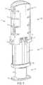
- FIG. 1is a perspective view of a medical injector in accordance with an embodiment of the present invention.
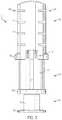
- FIG. 2is a first elevation view of a medical injector in accordance with an embodiment of the present invention.
- FIG. 3is a second elevation view of a medical injector in accordance with an embodiment of the present invention.
- FIG. 4is a third elevation view of a medical injector in accordance with an embodiment of the present invention.
- FIG. 5is a fourth elevation view of a medical injector in accordance with an embodiment of the present invention.
- FIG. 6is a fifth elevation view of a medical injector in accordance with an embodiment of the present invention.
- FIG. 7is a sixth elevation view of a medical injector in accordance with an embodiment of the present invention.
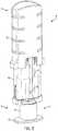
- FIG. 8is a perspective view of a medical injector in accordance with an embodiment of the present invention.
- FIG. 9is a perspective view of a medical injector in accordance with an embodiment of the present invention.
- FIG. 10is a perspective view of a medical injector in accordance with an embodiment of the present invention.
- distalrefers to a direction generally toward an end of a medical injector adapted for contact with a patient and/or engagement with a separate device
- proximalrefers to the opposite direction of distal, i.e., away from the end of a medical injector adapted for engagement with the separate device.
- FIGS. 1-10illustrate an exemplary embodiment of the present disclosure.
- a medical injector 10 of the present disclosureincludes an upper guard housing component 100 and a lower guard housing component 102 .
- the upper guard housing component 100surrounds the lower guard housing component 102 and is slidable relative thereto.
- the upper guard housing 100provides an enlarged gripping component 110 to aid a user in handling the medical injector 10 .
- the medical injector 10may include a first cap 30 and a second cap or cap remover 32 .
- the second cap 32can be secured to the medical injector 10 such that the second cap or cap remover 32 shields and covers a distal end 50 of a needle 14 and the first cap 30 .
- the first cap 30shields and covers a distal end 50 of a needle 14 .
- the first cap 30may be formed of a plastic and/or rubber guard material.
- the second cap 32may be the only cap that shields and covers the distal end 50 of the needle 14 .
- the second cap 32is engaged with the first cap 30 such that removal of the second cap 32 simultaneously removes the first cap 30 from the distal end 50 of the needle 14 .
- a medical injector 10 of the present disclosureincludes an upper guard housing component 100 and a lower guard housing component 102 .
- the medical injector 10includes a body having a distal end 34 and a proximal end 36 extending along a longitudinal axis L.
- a cross section of the medical injector 10 taken perpendicular to the longitudinal axis Lis non-circular in shape.
- a cross section of the medical injector 10may be generally elliptical in shape.
- the upper guard housing component 100includes a gripping component 110 , a viewing window 112 , and a guard or flange 114 .
- the gripping component 110includes gripping ribs 116 .
- the gripping component 110includes convex or concave details.
- the gripping ribs 116provide a gripping component that includes surfaces for accommodating a user's fingers.
- the gripping ribs 116provide ergonomically shaped surfaces that substantially conform to a user's fingertips to aid the user in handling and grasping the medical injector 10 .
- the gripping ribs 116circumferentially extend at least partially about an exterior surface of the upper guard housing.
- the gripping ribs 116improve the grip between the medical injector 10 and the user's fingertips.
- the gripping ribs 116are integrally formed with the upper guard housing component 100 and provide a visual and tactile cue to the user to instruct the user where to place his or her fingertips.
- the upper guard housing component 100includes a viewing window 112 that allows a user to be able to see a stopper 24 to improve control of the medical injector 10 .
- the lower guard housing component 102is formed of a transparent material. In this manner, a user can look through the viewing window 112 and is able to see the stopper 24 .
- the upper guard housing component 100includes a guard or flange 114 .
- the flange 114includes a first wing flange 117 and a second wing flange 118 .
- the first wing flange 117 and the second wing flange 118extend in generally opposite directions from the upper guard housing component 100 .
- a proximal surface of each of the first wing flange 117 and the second wing flange 118may be rounded or tapered for accommodating a user's fingers.
- the upper guard housing component 100and more particularly, the flange 114 , provides a visual and tactile cue to the user to instruct the user where to place his or her fingertips.
- the guard 114prevents a user from handling the medical injector 10 at a position too low.
- the upper guard housing component 100is moveable relative to the lower guard housing component 102 to advance the stopper 24 to expel a medicament out through the needle 14 .
- a stopper 24refers to a stopper assembly which may include a plunger, a stopper, or a combination thereof, for expelling the medicament from the medical injector 10 .
- the stopper 24is permanently affixed within a cavity 103 defined in a distal end of the upper guard housing. Alternatively, the stopper 24 may be secured therein via a variety of well-known securement methods.
- the upper guard housing component 100acts a drive member or actuation member for the medical injector 10 .
- the lower guard housing component 102includes a lower guard or lower flange 120 and a transparent body 122 .
- the lower guard housing component 102defines a reservoir 20 and a liquid medicament is disposed within the reservoir 20 .
- the transparent body 122provides a user with visual control of the medical injector 10 during an injection procedure.
- the lower guard or lower flange 120keeps an appropriate distance between the hand of a user and a skin surface of a patient during an injection procedure. For example, during an injection, as the upper guard housing component 100 moves distally with respect to the lower housing component 102 , the lower guard flange 120 will engage the upper guard flange 114 , thereby limiting the distal movement of the upper guard housing component 100 and the user's hand.
- the medical injector 10also includes a needle assembly 12 having a needle 14 , the reservoir 20 for medicament sealed by a septum 22 , a stopper 24 , a first cap 30 , and a second cap or a cap remover 32 .
- the stopper 24is engaged with a portion of the upper guard housing component 100 and is slidably disposed within the reservoir 20 .
- the stopper 24is sized to provide sealing engagement with an interior sidewall of the lower guard housing component 102 .
- the medical injector 10includes a distal end 34 and a proximal end 36 .
- the reservoir 20may be defined by the lower guard housing component 102 .
- the reservoir 20may be defined by a separate component contained within the lower guard housing component 102 , e.g., a cartridge or barrel.
- the needle assembly 12includes a needle 14 and a hub 38 .
- the needle 14includes a distal end 50 , formed for insertion into a patient, and a proximal end 52 .
- the medical injector 10 of the present disclosuremay be of various forms, including being a syringe, self-injector, auto-injector, or pen injector. In one embodiment, the medical injector 10 is well-suited for administering at least one fixed dose. In another embodiment, the medical injector 10 is well-suited for administering a series of fixed doses.
- the medical injector 10may be configured such that the upper guard housing component 100 is moveable relative to the lower guard housing component 102 to advance the stopper 24 to expel a medicament out through the needle 14 .
- the medical injector 10may include a reservoir 20 for accommodating an injectable medicament, which may be a drug cartridge or formed directly in the medical injector 10 .
- the reservoir 20may have one or more stoppers 24 associated therewith.
- a first cap 30shields and covers the distal end 50 of the needle 14 .
- the second cap or cap remover 32shields and covers the distal end 50 of the needle 14 and the first cap 30 .
- the second cap 32may be the only cap that shields and covers the distal end 50 of the needle 14 .
- the second cap or cap remover 32includes a cylindrical portion 130 and a distal flange 132 .
- the second cap 32is engaged with the first cap 30 such that removal of the second cap 32 simultaneously removes the first cap 30 from the distal end 50 of the needle 14 .
- the second cap 32provides a gripping component that includes surfaces for accommodating a user's fingers, such as distal flange 132 or similar structure.
- the distal flange 132 of the second cap 32provides ergonomically shaped surfaces that substantially conform to a user's fingertips to aid the user in removing the second cap 32 from the distal end 50 of the needle 14 and/or to aid the user in simultaneously removing the second cap 32 and the first cap 30 from the distal end 50 of the needle 14 .
- the distal flange 132 of the second cap 32provides a user with multiple finger grip positions for the user.
- the distal flange 132 of the second cap 32allows a user to handle and/or grip the second cap 32 in a variety of different ways.
- the shape of the second cap 32is designed to help disabled people more easily and more conveniently handle the second cap 32 and/or the medical injector 10 .
- the distal flange 132 of the second cap 32allows a user to handle the second cap 32 without finger flexion. In one embodiment, the distal flange 132 of the second cap 32 provides a gripping component that allows a user to better handle the second cap 32 and/or the medical injector 10 .
- the second cap 32is used to easily remove the second cap 32 and the first cap 30 from the distal end 50 of the needle 14 simultaneously. Referring to FIG. 10 , with the caps 30 , 32 removed, the distal end 50 of the needle 14 is exposed and ready to be positioned adjacent a desired portion of the skin of a user.
- the upper guard housing component 100can be moved in a direction generally along arrow A ( FIG. 10 ) to advance the stopper 24 and to expel a medicament out through the needle 14 .
- Movement of the upper guard housing component 100 in the direction generally along arrow Aactuates movement of the stopper 24 in the direction generally along arrow A toward the distal end 34 of the medical injector 10 .
- movement of the stopper 24 in the direction generally along arrow Aforces the medicament fluid contained within the reservoir 20 to be forced out the distal end 50 of the needle 14 and into the user and/or patient.
- the needle 14can be removed from the skin of the patient.
- the medical injector 10may include an automatic retraction mechanism for moving the needle 14 into the medical injector 10 for safe shielding of the needle 14 after use.
- a springmay be used as part of the automatic retraction mechanism.
- All of the components of the medical injector 10may be constructed of any known material, and are desirably constructed of medical-grade polymers.
Landscapes
- Health & Medical Sciences (AREA)
- Engineering & Computer Science (AREA)
- Hematology (AREA)
- Anesthesiology (AREA)
- Biomedical Technology (AREA)
- Heart & Thoracic Surgery (AREA)
- Vascular Medicine (AREA)
- Life Sciences & Earth Sciences (AREA)
- Animal Behavior & Ethology (AREA)
- General Health & Medical Sciences (AREA)
- Public Health (AREA)
- Veterinary Medicine (AREA)
- Environmental & Geological Engineering (AREA)
- Infusion, Injection, And Reservoir Apparatuses (AREA)
Abstract
Description
Claims (18)
Priority Applications (1)
| Application Number | Priority Date | Filing Date | Title |
|---|---|---|---|
| US15/372,591US10737036B2 (en) | 2015-12-08 | 2016-12-08 | Housing and cap for medical injector |
Applications Claiming Priority (2)
| Application Number | Priority Date | Filing Date | Title |
|---|---|---|---|
| US201562264501P | 2015-12-08 | 2015-12-08 | |
| US15/372,591US10737036B2 (en) | 2015-12-08 | 2016-12-08 | Housing and cap for medical injector |
Publications (2)
| Publication Number | Publication Date |
|---|---|
| US20170157331A1 US20170157331A1 (en) | 2017-06-08 |
| US10737036B2true US10737036B2 (en) | 2020-08-11 |
Family
ID=57570424
Family Applications (1)
| Application Number | Title | Priority Date | Filing Date |
|---|---|---|---|
| US15/372,591Active2038-08-21US10737036B2 (en) | 2015-12-08 | 2016-12-08 | Housing and cap for medical injector |
Country Status (2)
| Country | Link |
|---|---|
| US (1) | US10737036B2 (en) |
| WO (1) | WO2017098435A1 (en) |
Families Citing this family (1)
| Publication number | Priority date | Publication date | Assignee | Title |
|---|---|---|---|---|
| CN116251260B (en)* | 2023-03-29 | 2025-05-02 | 安徽天耘医疗器械有限公司 | Explosion-proof plug type prefilled syringe and method for achieving safe sterilization thereof |
Citations (66)
| Publication number | Priority date | Publication date | Assignee | Title |
|---|---|---|---|---|
| US2860635A (en)* | 1957-03-20 | 1958-11-18 | Edgar H Wilburn | Sterilizable and sterilized hypodermic syringe assemblies |
| US4365626A (en) | 1979-10-25 | 1982-12-28 | House Hugh A | Universal syringe |
| US4832695A (en) | 1985-09-23 | 1989-05-23 | Bruce Rosenberg | Tamper evident injection syringe |
| US4929232A (en) | 1989-03-30 | 1990-05-29 | Becton, Dickinson And Company | Syringe having tamper evidence features |
| USD337157S (en) | 1991-05-20 | 1993-07-06 | Ortiz German L | Replacement valve for endotracheal tube inflation cuff |
| USD375788S (en) | 1995-06-19 | 1996-11-19 | Ciba Corning Diagnostics Corp. | Ampule adapter |
| USD380262S (en) | 1995-06-26 | 1997-06-24 | Minimed Inc. | Quick disconnect coupling |
| US5647849A (en) | 1995-09-27 | 1997-07-15 | Becton, Dickinson And Company | Self-contained safety syringe |
| USD427308S (en) | 1999-01-22 | 2000-06-27 | Medimop Medical Projects Ltd. | Vial adapter |
| US20010044606A1 (en) | 1998-04-15 | 2001-11-22 | Inkpen Thomas Randall | Needle injection-facilitating device |
| USD473646S1 (en) | 2001-12-21 | 2003-04-22 | Microsurgical Technology, Inc. | Irrigation/aspiration instrument connector |
| US6582397B2 (en) | 2001-06-19 | 2003-06-24 | Portex, Inc. | Needle safety device with antiremoval protection |
| WO2003051423A2 (en) | 2001-12-13 | 2003-06-26 | Becton Dickinson And Company | Needle closure system removal device |
| USD483487S1 (en) | 2002-12-19 | 2003-12-09 | Becton Dickinson And Company | Stopcock device |
| USD486225S1 (en) | 2002-11-22 | 2004-02-03 | Pbm Plastics, Inc. | Breast pump adapter |
| USD492774S1 (en) | 2003-03-10 | 2004-07-06 | Becton Dickinson And Company | Introducer needle assembly |
| US20040133172A1 (en) | 2002-06-07 | 2004-07-08 | Becton, Dickinson And Company | Needle safety device |
| US20040210197A1 (en) | 2003-04-16 | 2004-10-21 | Conway Hugh T | Safety shielding needle assembly with passive shielding |
| USD497990S1 (en) | 2003-03-13 | 2004-11-02 | Schering Oy | Implant inserter |
| WO2005025636A2 (en) | 2003-09-17 | 2005-03-24 | Dali Medical Devices Ltd. | Automatic injection device |
| USD505200S1 (en) | 2003-09-09 | 2005-05-17 | Smiths Medical Asd, Inc. | Fixed needle assembly |
| US7059327B2 (en) | 2002-01-23 | 2006-06-13 | Kapitex Healthcare Limited | Tracheostoma valve |
| US20080228147A1 (en) | 2007-03-15 | 2008-09-18 | Bristol-Myers Squibb Company | Injector for use with pre-filled syringes and method of assembly |
| USD605755S1 (en) | 2007-03-23 | 2009-12-08 | Smiths Medical Asd, Inc. | Oval tapering blunt cannula proximal portion |
| US20090312705A1 (en) | 2006-04-11 | 2009-12-17 | Guillaume Grunhut | Automatic Injection Device |
| USD607558S1 (en) | 2008-09-19 | 2010-01-05 | Becton Dickinson France S.A.S. | Medicine injector |
| USD629510S1 (en) | 2008-03-14 | 2010-12-21 | Becton, Dickinson And Company | Cap |
| USD633199S1 (en) | 2009-10-05 | 2011-02-22 | Pyng Medical Corp. | Insertion tool for bone portals |
| US20110092915A1 (en) | 2009-10-16 | 2011-04-21 | Centocor | Palm activated drug delivery device |
| USD637713S1 (en) | 2009-11-20 | 2011-05-10 | Carmel Pharma Ab | Medical device adaptor |
| USD642261S1 (en) | 2010-09-15 | 2011-07-26 | Abbott Medical Optics Inc. | Securing device for cannula attachment to syringe body |
| US20120029439A1 (en) | 2008-11-17 | 2012-02-02 | Christopher Hudson | Syringe and needle cover remover |
| USD655000S1 (en) | 2010-01-13 | 2012-02-28 | Mirigian Aram J | Syringe holder |
| USD655017S1 (en) | 2010-06-17 | 2012-02-28 | Yukon Medical, Llc | Shroud |
| USD679008S1 (en) | 2011-01-07 | 2013-03-26 | Remot Medical Innovation, LLC | Endotracheal tube adaptor |
| US20130085453A1 (en) | 2011-09-30 | 2013-04-04 | Becton Dickinson France, S.A.S. | Syringe Having a Squeeze-Fit Plunger Rod |
| USD681230S1 (en) | 2011-09-08 | 2013-04-30 | Yukon Medical, Llc | Shroud |
| USD702343S1 (en) | 2008-08-27 | 2014-04-08 | Deka Products Limited Partnership | Fluidic connector |
| USD702835S1 (en) | 2012-01-04 | 2014-04-15 | Anteis Sa | Needle retaining device |
| USD709753S1 (en) | 2013-05-23 | 2014-07-29 | Industrie Borla, S.P.A. | Locking cannula |
| WO2014150201A1 (en) | 2013-03-15 | 2014-09-25 | Janssen Biotech, Inc. | Palm activated drug delivery device |
| WO2014154498A1 (en) | 2013-03-25 | 2014-10-02 | Carebay Europe Ltd | Front cap for a medicament delivery device |
| US8858507B2 (en) | 2009-03-03 | 2014-10-14 | Novo Nordisk A/S | Cap lock |
| US8858508B2 (en)* | 2003-07-31 | 2014-10-14 | West Pharmaceuticals Services of Delaware, Inc. | Syringe with automatically triggered safety sleeve |
| USD718439S1 (en) | 2012-12-17 | 2014-11-25 | B. Braun Melsungen Ag | Actuator assembly for a valved catheter |
| WO2015014363A2 (en) | 2013-08-02 | 2015-02-05 | Union Medico Aps | Injection device |
| US20150045729A1 (en) | 2011-04-20 | 2015-02-12 | Amgen, Inc. | Autoinjector apparatus |
| WO2015073740A2 (en) | 2013-11-13 | 2015-05-21 | Genentech, Inc. | Assisted manual injector devices and methods |
| WO2015105511A1 (en) | 2014-01-13 | 2015-07-16 | West Pharmaceutical Services, Inc. | Rigid needle shield with pivotable arms |
| WO2015123096A1 (en) | 2014-02-11 | 2015-08-20 | Eli Lilly And Company | Rigid needle shield gripping cap assembly |
| USD738494S1 (en) | 2013-03-05 | 2015-09-08 | Ikashmore Pty Ltd | Blood collection safety device |
| US20150258283A1 (en)* | 2014-03-11 | 2015-09-17 | Terumo Kabushiki Kaisha | Liquid administration device |
| EP2923716A1 (en) | 2014-03-28 | 2015-09-30 | Sanofi-Aventis Deutschland GmbH | Cap having a sheath removal mechanism |
| USD750258S1 (en) | 2013-09-06 | 2016-02-23 | Asalus Medical Instruments Ltd | Medical instrument |
| USD750239S1 (en) | 2013-10-31 | 2016-02-23 | Nordson Corporation | Adapter collar for a syringe |
| USD750779S1 (en) | 2014-03-11 | 2016-03-01 | Prabhat Kumar Ahluwalia | Medical device |
| USD751192S1 (en) | 2014-05-14 | 2016-03-08 | Health Line International Corp. | Medical device |
| USD755966S1 (en) | 2014-03-11 | 2016-05-10 | Prabhat Kumar Ahluwalia | Medical device |
| USD755967S1 (en) | 2014-03-11 | 2016-05-10 | Prabhat Kumar Ahluwalia | Medical device |
| USD757258S1 (en) | 2013-04-11 | 2016-05-24 | Aesculap Ag | Container seal |
| USD757935S1 (en) | 2014-02-06 | 2016-05-31 | Karl Storz Endoscopy-America, Inc. | Rotation wheel extension |
| USD760891S1 (en) | 2014-02-12 | 2016-07-05 | Abbvie Inc. | Injection tool |
| USD761422S1 (en) | 2009-08-28 | 2016-07-12 | Resmed Limited | Air delivery tube with cuff |
| USD765241S1 (en) | 2014-09-15 | 2016-08-30 | Owen Mumford Ltd. | Syringe |
| USD768851S1 (en) | 2014-06-30 | 2016-10-11 | Htl-Strefa Spolka Akcyjna | Safety needle device |
| USD768850S1 (en) | 2013-10-29 | 2016-10-11 | Htl-Strefa Spolka Akcyjna | Needle shield |
- 2016
- 2016-12-08USUS15/372,591patent/US10737036B2/enactiveActive
- 2016-12-08WOPCT/IB2016/057443patent/WO2017098435A1/ennot_activeCeased
Patent Citations (71)
| Publication number | Priority date | Publication date | Assignee | Title |
|---|---|---|---|---|
| US2860635A (en)* | 1957-03-20 | 1958-11-18 | Edgar H Wilburn | Sterilizable and sterilized hypodermic syringe assemblies |
| US4365626A (en) | 1979-10-25 | 1982-12-28 | House Hugh A | Universal syringe |
| US4832695A (en) | 1985-09-23 | 1989-05-23 | Bruce Rosenberg | Tamper evident injection syringe |
| US4929232A (en) | 1989-03-30 | 1990-05-29 | Becton, Dickinson And Company | Syringe having tamper evidence features |
| USD337157S (en) | 1991-05-20 | 1993-07-06 | Ortiz German L | Replacement valve for endotracheal tube inflation cuff |
| USD375788S (en) | 1995-06-19 | 1996-11-19 | Ciba Corning Diagnostics Corp. | Ampule adapter |
| USD380262S (en) | 1995-06-26 | 1997-06-24 | Minimed Inc. | Quick disconnect coupling |
| US5647849A (en) | 1995-09-27 | 1997-07-15 | Becton, Dickinson And Company | Self-contained safety syringe |
| US20010044606A1 (en) | 1998-04-15 | 2001-11-22 | Inkpen Thomas Randall | Needle injection-facilitating device |
| USD427308S (en) | 1999-01-22 | 2000-06-27 | Medimop Medical Projects Ltd. | Vial adapter |
| US6582397B2 (en) | 2001-06-19 | 2003-06-24 | Portex, Inc. | Needle safety device with antiremoval protection |
| WO2003051423A2 (en) | 2001-12-13 | 2003-06-26 | Becton Dickinson And Company | Needle closure system removal device |
| USD473646S1 (en) | 2001-12-21 | 2003-04-22 | Microsurgical Technology, Inc. | Irrigation/aspiration instrument connector |
| US7059327B2 (en) | 2002-01-23 | 2006-06-13 | Kapitex Healthcare Limited | Tracheostoma valve |
| US20040133172A1 (en) | 2002-06-07 | 2004-07-08 | Becton, Dickinson And Company | Needle safety device |
| USD486225S1 (en) | 2002-11-22 | 2004-02-03 | Pbm Plastics, Inc. | Breast pump adapter |
| USD483487S1 (en) | 2002-12-19 | 2003-12-09 | Becton Dickinson And Company | Stopcock device |
| USD492774S1 (en) | 2003-03-10 | 2004-07-06 | Becton Dickinson And Company | Introducer needle assembly |
| USD497990S1 (en) | 2003-03-13 | 2004-11-02 | Schering Oy | Implant inserter |
| US20040210197A1 (en) | 2003-04-16 | 2004-10-21 | Conway Hugh T | Safety shielding needle assembly with passive shielding |
| US8858508B2 (en)* | 2003-07-31 | 2014-10-14 | West Pharmaceuticals Services of Delaware, Inc. | Syringe with automatically triggered safety sleeve |
| USD505200S1 (en) | 2003-09-09 | 2005-05-17 | Smiths Medical Asd, Inc. | Fixed needle assembly |
| WO2005025636A2 (en) | 2003-09-17 | 2005-03-24 | Dali Medical Devices Ltd. | Automatic injection device |
| US20070129686A1 (en) | 2003-09-17 | 2007-06-07 | Dali Medical Devices Ltd. | Automatic injection device |
| US20090312705A1 (en) | 2006-04-11 | 2009-12-17 | Guillaume Grunhut | Automatic Injection Device |
| US20080228147A1 (en) | 2007-03-15 | 2008-09-18 | Bristol-Myers Squibb Company | Injector for use with pre-filled syringes and method of assembly |
| USD605755S1 (en) | 2007-03-23 | 2009-12-08 | Smiths Medical Asd, Inc. | Oval tapering blunt cannula proximal portion |
| USD629510S1 (en) | 2008-03-14 | 2010-12-21 | Becton, Dickinson And Company | Cap |
| USD702343S1 (en) | 2008-08-27 | 2014-04-08 | Deka Products Limited Partnership | Fluidic connector |
| USD607558S1 (en) | 2008-09-19 | 2010-01-05 | Becton Dickinson France S.A.S. | Medicine injector |
| US20120029439A1 (en) | 2008-11-17 | 2012-02-02 | Christopher Hudson | Syringe and needle cover remover |
| US8858507B2 (en) | 2009-03-03 | 2014-10-14 | Novo Nordisk A/S | Cap lock |
| USD761422S1 (en) | 2009-08-28 | 2016-07-12 | Resmed Limited | Air delivery tube with cuff |
| USD633199S1 (en) | 2009-10-05 | 2011-02-22 | Pyng Medical Corp. | Insertion tool for bone portals |
| US20110092915A1 (en) | 2009-10-16 | 2011-04-21 | Centocor | Palm activated drug delivery device |
| USD637713S1 (en) | 2009-11-20 | 2011-05-10 | Carmel Pharma Ab | Medical device adaptor |
| USD655000S1 (en) | 2010-01-13 | 2012-02-28 | Mirigian Aram J | Syringe holder |
| USD655017S1 (en) | 2010-06-17 | 2012-02-28 | Yukon Medical, Llc | Shroud |
| USD642261S1 (en) | 2010-09-15 | 2011-07-26 | Abbott Medical Optics Inc. | Securing device for cannula attachment to syringe body |
| USD679008S1 (en) | 2011-01-07 | 2013-03-26 | Remot Medical Innovation, LLC | Endotracheal tube adaptor |
| US20150045729A1 (en) | 2011-04-20 | 2015-02-12 | Amgen, Inc. | Autoinjector apparatus |
| USD681230S1 (en) | 2011-09-08 | 2013-04-30 | Yukon Medical, Llc | Shroud |
| US20130085453A1 (en) | 2011-09-30 | 2013-04-04 | Becton Dickinson France, S.A.S. | Syringe Having a Squeeze-Fit Plunger Rod |
| USD702835S1 (en) | 2012-01-04 | 2014-04-15 | Anteis Sa | Needle retaining device |
| USD718439S1 (en) | 2012-12-17 | 2014-11-25 | B. Braun Melsungen Ag | Actuator assembly for a valved catheter |
| USD738494S1 (en) | 2013-03-05 | 2015-09-08 | Ikashmore Pty Ltd | Blood collection safety device |
| WO2014150201A1 (en) | 2013-03-15 | 2014-09-25 | Janssen Biotech, Inc. | Palm activated drug delivery device |
| WO2014154498A1 (en) | 2013-03-25 | 2014-10-02 | Carebay Europe Ltd | Front cap for a medicament delivery device |
| US20160144132A1 (en) | 2013-03-25 | 2016-05-26 | Carebay Europe Ltd | Front Cap for a Medicament Delivery Device |
| USD757258S1 (en) | 2013-04-11 | 2016-05-24 | Aesculap Ag | Container seal |
| USD709753S1 (en) | 2013-05-23 | 2014-07-29 | Industrie Borla, S.P.A. | Locking cannula |
| WO2015014363A2 (en) | 2013-08-02 | 2015-02-05 | Union Medico Aps | Injection device |
| US20160193428A1 (en) | 2013-08-02 | 2016-07-07 | Union Medico Aps | Injection device |
| USD750258S1 (en) | 2013-09-06 | 2016-02-23 | Asalus Medical Instruments Ltd | Medical instrument |
| USD768850S1 (en) | 2013-10-29 | 2016-10-11 | Htl-Strefa Spolka Akcyjna | Needle shield |
| USD750239S1 (en) | 2013-10-31 | 2016-02-23 | Nordson Corporation | Adapter collar for a syringe |
| WO2015073740A2 (en) | 2013-11-13 | 2015-05-21 | Genentech, Inc. | Assisted manual injector devices and methods |
| US20150165129A1 (en) | 2013-11-13 | 2015-06-18 | Genentech, Inc. | Assisted manual injector devices and methods |
| WO2015105511A1 (en) | 2014-01-13 | 2015-07-16 | West Pharmaceutical Services, Inc. | Rigid needle shield with pivotable arms |
| USD757935S1 (en) | 2014-02-06 | 2016-05-31 | Karl Storz Endoscopy-America, Inc. | Rotation wheel extension |
| WO2015123096A1 (en) | 2014-02-11 | 2015-08-20 | Eli Lilly And Company | Rigid needle shield gripping cap assembly |
| USD760891S1 (en) | 2014-02-12 | 2016-07-05 | Abbvie Inc. | Injection tool |
| USD755967S1 (en) | 2014-03-11 | 2016-05-10 | Prabhat Kumar Ahluwalia | Medical device |
| USD755966S1 (en) | 2014-03-11 | 2016-05-10 | Prabhat Kumar Ahluwalia | Medical device |
| USD750779S1 (en) | 2014-03-11 | 2016-03-01 | Prabhat Kumar Ahluwalia | Medical device |
| US20150258283A1 (en)* | 2014-03-11 | 2015-09-17 | Terumo Kabushiki Kaisha | Liquid administration device |
| EP2923716A1 (en) | 2014-03-28 | 2015-09-30 | Sanofi-Aventis Deutschland GmbH | Cap having a sheath removal mechanism |
| US20170014578A1 (en) | 2014-03-28 | 2017-01-19 | Sanofi-Aventis Deutschland Gmbh | Sheath removal mechanism |
| USD751192S1 (en) | 2014-05-14 | 2016-03-08 | Health Line International Corp. | Medical device |
| USD768851S1 (en) | 2014-06-30 | 2016-10-11 | Htl-Strefa Spolka Akcyjna | Safety needle device |
| USD765241S1 (en) | 2014-09-15 | 2016-08-30 | Owen Mumford Ltd. | Syringe |
Also Published As
| Publication number | Publication date |
|---|---|
| US20170157331A1 (en) | 2017-06-08 |
| WO2017098435A1 (en) | 2017-06-15 |
Similar Documents
| Publication | Publication Date | Title |
|---|---|---|
| US11701476B2 (en) | Cap for medical injector | |
| US11154662B2 (en) | Cap with hemisphere portion for medical injector | |
| JP2020099832A (en) | Medical injector and cap remover | |
| US10737036B2 (en) | Housing and cap for medical injector |
Legal Events
| Date | Code | Title | Description |
|---|---|---|---|
| AS | Assignment | Owner name:BECTON DICKINSON FRANCE S.A.S., FRANCE Free format text:ASSIGNMENT OF ASSIGNORS INTEREST;ASSIGNORS:CORBIN, JEAN-YVES;VAUPRES, MAXIME;REEL/FRAME:040902/0029 Effective date:20170106 | |
| STPP | Information on status: patent application and granting procedure in general | Free format text:DOCKETED NEW CASE - READY FOR EXAMINATION | |
| STPP | Information on status: patent application and granting procedure in general | Free format text:NON FINAL ACTION MAILED | |
| STPP | Information on status: patent application and granting procedure in general | Free format text:RESPONSE TO NON-FINAL OFFICE ACTION ENTERED AND FORWARDED TO EXAMINER | |
| STPP | Information on status: patent application and granting procedure in general | Free format text:NON FINAL ACTION MAILED | |
| STPP | Information on status: patent application and granting procedure in general | Free format text:NOTICE OF ALLOWANCE MAILED -- APPLICATION RECEIVED IN OFFICE OF PUBLICATIONS | |
| STPP | Information on status: patent application and granting procedure in general | Free format text:PUBLICATIONS -- ISSUE FEE PAYMENT VERIFIED | |
| STCF | Information on status: patent grant | Free format text:PATENTED CASE | |
| CC | Certificate of correction | ||
| MAFP | Maintenance fee payment | Free format text:PAYMENT OF MAINTENANCE FEE, 4TH YEAR, LARGE ENTITY (ORIGINAL EVENT CODE: M1551); ENTITY STATUS OF PATENT OWNER: LARGE ENTITY Year of fee payment:4 |