US10736746B2 - Extra-articular implantable mechanical energy absorbing systems - Google Patents
Extra-articular implantable mechanical energy absorbing systemsDownload PDFInfo
- Publication number
- US10736746B2 US10736746B2US11/743,605US74360507AUS10736746B2US 10736746 B2US10736746 B2US 10736746B2US 74360507 AUS74360507 AUS 74360507AUS 10736746 B2US10736746 B2US 10736746B2
- Authority
- US
- United States
- Prior art keywords
- energy
- joint
- knee joint
- spring
- assembly
- Prior art date
- Legal status (The legal status is an assumption and is not a legal conclusion. Google has not performed a legal analysis and makes no representation as to the accuracy of the status listed.)
- Active, expires
Links
- 210000000988bone and boneAnatomy0.000claimsabstractdescription77
- 238000000034methodMethods0.000claimsabstractdescription49
- 230000033001locomotionEffects0.000claimsdescription53
- 210000000629knee jointAnatomy0.000claimsdescription33
- 201000008482osteoarthritisDiseases0.000claimsdescription31
- 208000002193PainDiseases0.000claimsdescription28
- 210000003127kneeAnatomy0.000claimsdescription28
- 239000006096absorbing agentSubstances0.000claimsdescription25
- 230000005021gaitEffects0.000claimsdescription21
- 230000006835compressionEffects0.000claimsdescription16
- 238000007906compressionMethods0.000claimsdescription16
- 230000003349osteoarthritic effectEffects0.000claimsdescription15
- 210000001188articular cartilageAnatomy0.000claimsdescription7
- 208000006820ArthralgiaDiseases0.000claimsdescription6
- 230000004048modificationEffects0.000claimsdescription6
- 238000012986modificationMethods0.000claimsdescription6
- 208000024765knee painDiseases0.000claims2
- 238000013459approachMethods0.000description73
- 210000003484anatomyAnatomy0.000description62
- 210000001503jointAnatomy0.000description62
- 238000010521absorption reactionMethods0.000description49
- 230000000712assemblyEffects0.000description38
- 238000000429assemblyMethods0.000description38
- 238000005452bendingMethods0.000description38
- 210000000845cartilageAnatomy0.000description31
- 210000001519tissueAnatomy0.000description31
- 238000012546transferMethods0.000description22
- 230000006870functionEffects0.000description15
- 238000011882arthroplastyMethods0.000description13
- 238000006073displacement reactionMethods0.000description12
- 230000007246mechanismEffects0.000description11
- 239000000463materialSubstances0.000description10
- 238000011282treatmentMethods0.000description10
- 230000036961partial effectEffects0.000description9
- 206010003246arthritisDiseases0.000description8
- 210000001612chondrocyteAnatomy0.000description8
- 238000002513implantationMethods0.000description8
- 239000007943implantSubstances0.000description7
- 230000000295complement effectEffects0.000description6
- 239000003814drugSubstances0.000description6
- 229940079593drugDrugs0.000description6
- 230000000694effectsEffects0.000description6
- 210000002435tendonAnatomy0.000description6
- 230000007704transitionEffects0.000description6
- 230000009471actionEffects0.000description5
- 230000002146bilateral effectEffects0.000description5
- 210000002683footAnatomy0.000description5
- 210000003906tibiofibular jointAnatomy0.000description5
- 230000009286beneficial effectEffects0.000description4
- 230000008901benefitEffects0.000description4
- 230000001054cortical effectEffects0.000description4
- 125000004122cyclic groupChemical group0.000description4
- 239000012530fluidSubstances0.000description4
- 210000000281joint capsuleAnatomy0.000description4
- 230000037230mobilityEffects0.000description4
- 210000003205muscleAnatomy0.000description4
- 238000011084recoveryMethods0.000description4
- 230000035939shockEffects0.000description4
- 210000002832shoulderAnatomy0.000description4
- 230000035882stressEffects0.000description4
- 238000013519translationMethods0.000description4
- 210000000689upper legAnatomy0.000description4
- 206010061218InflammationDiseases0.000description3
- 230000002917arthritic effectEffects0.000description3
- 210000004027cellAnatomy0.000description3
- 238000013461designMethods0.000description3
- 208000037265diseases, disorders, signs and symptomsDiseases0.000description3
- 210000000968fibrocartilageAnatomy0.000description3
- 230000035876healingEffects0.000description3
- 210000001624hipAnatomy0.000description3
- 230000004054inflammatory processEffects0.000description3
- 210000003041ligamentAnatomy0.000description3
- 239000011159matrix materialSubstances0.000description3
- 230000000877morphologic effectEffects0.000description3
- 230000004044responseEffects0.000description3
- 206010039073rheumatoid arthritisDiseases0.000description3
- 210000003491skinAnatomy0.000description3
- 238000001356surgical procedureMethods0.000description3
- 208000024891symptomDiseases0.000description3
- 210000001179synovial fluidAnatomy0.000description3
- 210000002303tibiaAnatomy0.000description3
- 241000112853ArthrodesSpecies0.000description2
- 102000008186CollagenHuman genes0.000description2
- 108010035532CollagenProteins0.000description2
- 241000282412HomoSpecies0.000description2
- 208000012659Joint diseaseDiseases0.000description2
- 241000124008MammaliaSpecies0.000description2
- -1PolypropylenePolymers0.000description2
- 241000251539Vertebrata <Metazoa>Species0.000description2
- 210000003423ankleAnatomy0.000description2
- 230000006907apoptotic processEffects0.000description2
- 210000004204blood vesselAnatomy0.000description2
- 239000002775capsuleSubstances0.000description2
- 230000001413cellular effectEffects0.000description2
- 239000011248coating agentSubstances0.000description2
- 238000000576coating methodMethods0.000description2
- 229920001436collagenPolymers0.000description2
- 210000004439collateral ligamentAnatomy0.000description2
- 210000002808connective tissueAnatomy0.000description2
- 230000003247decreasing effectEffects0.000description2
- 201000010099diseaseDiseases0.000description2
- 238000012377drug deliveryMethods0.000description2
- 239000000835fiberSubstances0.000description2
- 210000003108foot jointAnatomy0.000description2
- 210000003035hyaline cartilageAnatomy0.000description2
- 230000002706hydrostatic effectEffects0.000description2
- 230000003116impacting effectEffects0.000description2
- 230000013011matingEffects0.000description2
- 230000003387muscularEffects0.000description2
- 210000000056organAnatomy0.000description2
- 238000012829orthopaedic surgeryMethods0.000description2
- 230000001737promoting effectEffects0.000description2
- 230000009467reductionEffects0.000description2
- 230000008439repair processEffects0.000description2
- 238000002271resectionMethods0.000description2
- 125000006850spacer groupChemical group0.000description2
- 230000000638stimulationEffects0.000description2
- 210000001258synovial membraneAnatomy0.000description2
- 238000002560therapeutic procedureMethods0.000description2
- 230000009184walkingEffects0.000description2
- 210000000707wristAnatomy0.000description2
- 206010053555Arthritis bacterialDiseases0.000description1
- 206010060968Arthritis infectiveDiseases0.000description1
- 206010003694AtrophyDiseases0.000description1
- 208000023275Autoimmune diseaseDiseases0.000description1
- 206010006784Burning sensationDiseases0.000description1
- 241000251730ChondrichthyesSpecies0.000description1
- 208000000094Chronic PainDiseases0.000description1
- 241000252210CyprinidaeSpecies0.000description1
- 229920004934Dacron®Polymers0.000description1
- 102000016942ElastinHuman genes0.000description1
- 108010014258ElastinProteins0.000description1
- 201000005569GoutDiseases0.000description1
- 206010018634Gouty ArthritisDiseases0.000description1
- 208000004575Infectious ArthritisDiseases0.000description1
- 208000007101Muscle CrampDiseases0.000description1
- 239000004698PolyethyleneSubstances0.000description1
- 239000004743PolypropyleneSubstances0.000description1
- 102000016611ProteoglycansHuman genes0.000description1
- 108010067787ProteoglycansProteins0.000description1
- 201000001263Psoriatic ArthritisDiseases0.000description1
- 208000036824Psoriatic arthropathyDiseases0.000description1
- 208000005392SpasmDiseases0.000description1
- 208000013201Stress fractureDiseases0.000description1
- 201000010814SynostosisDiseases0.000description1
- LEHOTFFKMJEONL-UHFFFAOYSA-NUric AcidChemical groupN1C(=O)NC(=O)C2=C1NC(=O)N2LEHOTFFKMJEONL-UHFFFAOYSA-N0.000description1
- TVWHNULVHGKJHS-UHFFFAOYSA-NUric acidNatural productsN1C(=O)NC(=O)C2NC(=O)NC21TVWHNULVHGKJHS-UHFFFAOYSA-N0.000description1
- 230000005856abnormalityEffects0.000description1
- 230000032683agingEffects0.000description1
- 238000004458analytical methodMethods0.000description1
- 238000004873anchoringMethods0.000description1
- 230000003466anti-cipated effectEffects0.000description1
- 210000001367arteryAnatomy0.000description1
- 230000037444atrophyEffects0.000description1
- 230000001851biosynthetic effectEffects0.000description1
- 230000015572biosynthetic processEffects0.000description1
- 239000008280bloodSubstances0.000description1
- 210000004369bloodAnatomy0.000description1
- 230000010256bone depositionEffects0.000description1
- 210000001185bone marrowAnatomy0.000description1
- 210000004556brainAnatomy0.000description1
- 229910000389calcium phosphateInorganic materials0.000description1
- 239000001506calcium phosphateSubstances0.000description1
- 235000011010calcium phosphatesNutrition0.000description1
- 230000005779cell damageEffects0.000description1
- 230000030833cell deathEffects0.000description1
- 230000008859changeEffects0.000description1
- 239000003795chemical substances by applicationSubstances0.000description1
- 210000000038chestAnatomy0.000description1
- 230000009194climbingEffects0.000description1
- 238000002591computed tomographyMethods0.000description1
- 230000008602contractionEffects0.000description1
- 238000012937correctionMethods0.000description1
- 239000002537cosmeticSubstances0.000description1
- 239000013078crystalSubstances0.000description1
- 230000001186cumulative effectEffects0.000description1
- 238000005520cutting processMethods0.000description1
- 230000006378damageEffects0.000description1
- 238000001804debridementMethods0.000description1
- 230000003412degenerative effectEffects0.000description1
- 230000001419dependent effectEffects0.000description1
- 230000008021depositionEffects0.000description1
- 238000012631diagnostic techniqueMethods0.000description1
- 238000010586diagramMethods0.000description1
- 208000035475disorderDiseases0.000description1
- 238000009826distributionMethods0.000description1
- 239000003937drug carrierSubstances0.000description1
- 230000004064dysfunctionEffects0.000description1
- 210000001162elastic cartilageAnatomy0.000description1
- 239000013013elastic materialSubstances0.000description1
- 229920002549elastinPolymers0.000description1
- 238000004146energy storageMethods0.000description1
- 230000003628erosive effectEffects0.000description1
- 229920000295expanded polytetrafluoroethylenePolymers0.000description1
- 210000003414extremityAnatomy0.000description1
- 210000003811fingerAnatomy0.000description1
- 210000001145finger jointAnatomy0.000description1
- 230000009760functional impairmentEffects0.000description1
- 210000004247handAnatomy0.000description1
- 210000002478hand jointAnatomy0.000description1
- 230000011132hemopoiesisEffects0.000description1
- 210000002758humerusAnatomy0.000description1
- 238000000338in vitroMethods0.000description1
- 208000015181infectious diseaseDiseases0.000description1
- 230000002757inflammatory effectEffects0.000description1
- 208000014674injuryDiseases0.000description1
- 230000002427irreversible effectEffects0.000description1
- 230000009191jumpingEffects0.000description1
- 210000002414legAnatomy0.000description1
- 210000003141lower extremityAnatomy0.000description1
- 238000002595magnetic resonance imagingMethods0.000description1
- 210000004373mandibleAnatomy0.000description1
- 238000004519manufacturing processMethods0.000description1
- 210000002050maxillaAnatomy0.000description1
- 239000012528membraneSubstances0.000description1
- 230000005499meniscusEffects0.000description1
- 210000005036nerveAnatomy0.000description1
- 235000015097nutrientsNutrition0.000description1
- 239000011295pitchSubstances0.000description1
- 229920000573polyethylenePolymers0.000description1
- 239000005020polyethylene terephthalateSubstances0.000description1
- 229920001155polypropylenePolymers0.000description1
- 229920001296polysiloxanePolymers0.000description1
- 229920001343polytetrafluoroethylenePolymers0.000description1
- 239000004810polytetrafluoroethyleneSubstances0.000description1
- 239000011148porous materialSubstances0.000description1
- 230000002980postoperative effectEffects0.000description1
- 238000004321preservationMethods0.000description1
- 230000008569processEffects0.000description1
- 230000002829reductive effectEffects0.000description1
- 238000007634remodelingMethods0.000description1
- 230000003252repetitive effectEffects0.000description1
- 238000011160researchMethods0.000description1
- 230000009183runningEffects0.000description1
- 231100000241scarToxicity0.000description1
- 201000001223septic arthritisDiseases0.000description1
- 229910052709silverInorganic materials0.000description1
- 239000004332silverSubstances0.000description1
- 210000003625skullAnatomy0.000description1
- 210000004872soft tissueAnatomy0.000description1
- 210000000278spinal cordAnatomy0.000description1
- 230000009192sprintingEffects0.000description1
- 230000004936stimulating effectEffects0.000description1
- 238000003860storageMethods0.000description1
- 239000000126substanceSubstances0.000description1
- 230000001502supplementing effectEffects0.000description1
- 230000002459sustained effectEffects0.000description1
- 238000013268sustained releaseMethods0.000description1
- 239000012730sustained-release formSubstances0.000description1
- 229920002994synthetic fiberPolymers0.000description1
- 210000003813thumbAnatomy0.000description1
- 230000008733traumaEffects0.000description1
- 230000000472traumatic effectEffects0.000description1
- 238000011277treatment modalityMethods0.000description1
- QORWJWZARLRLPR-UHFFFAOYSA-Htricalcium bis(phosphate)Chemical compound[Ca+2].[Ca+2].[Ca+2].[O-]P([O-])([O-])=O.[O-]P([O-])([O-])=OQORWJWZARLRLPR-UHFFFAOYSA-H0.000description1
- 210000000623ulnaAnatomy0.000description1
- 238000002604ultrasonographyMethods0.000description1
- 210000001364upper extremityAnatomy0.000description1
- 229940116269uric acidDrugs0.000description1
- 210000003462veinAnatomy0.000description1
- 210000002517zygapophyseal jointAnatomy0.000description1
Images


Classifications
- A—HUMAN NECESSITIES
- A61—MEDICAL OR VETERINARY SCIENCE; HYGIENE
- A61B—DIAGNOSIS; SURGERY; IDENTIFICATION
- A61B17/00—Surgical instruments, devices or methods
- A61B17/56—Surgical instruments or methods for treatment of bones or joints; Devices specially adapted therefor
- A—HUMAN NECESSITIES
- A61—MEDICAL OR VETERINARY SCIENCE; HYGIENE
- A61B—DIAGNOSIS; SURGERY; IDENTIFICATION
- A61B17/00—Surgical instruments, devices or methods
- A61B17/56—Surgical instruments or methods for treatment of bones or joints; Devices specially adapted therefor
- A61B17/562—Implants for placement in joint gaps without restricting joint motion, e.g. to reduce arthritic pain
- A—HUMAN NECESSITIES
- A61—MEDICAL OR VETERINARY SCIENCE; HYGIENE
- A61B—DIAGNOSIS; SURGERY; IDENTIFICATION
- A61B17/00—Surgical instruments, devices or methods
- A61B17/56—Surgical instruments or methods for treatment of bones or joints; Devices specially adapted therefor
- A61B17/58—Surgical instruments or methods for treatment of bones or joints; Devices specially adapted therefor for osteosynthesis, e.g. bone plates, screws or setting implements
- A61B17/68—Internal fixation devices, including fasteners and spinal fixators, even if a part thereof projects from the skin
- A61B17/80—Cortical plates, i.e. bone plates; Instruments for holding or positioning cortical plates, or for compressing bones attached to cortical plates
- A61B17/8004—Cortical plates, i.e. bone plates; Instruments for holding or positioning cortical plates, or for compressing bones attached to cortical plates with means for distracting or compressing the bone or bones
- A—HUMAN NECESSITIES
- A61—MEDICAL OR VETERINARY SCIENCE; HYGIENE
- A61B—DIAGNOSIS; SURGERY; IDENTIFICATION
- A61B17/00—Surgical instruments, devices or methods
- A61B17/56—Surgical instruments or methods for treatment of bones or joints; Devices specially adapted therefor
- A61B17/58—Surgical instruments or methods for treatment of bones or joints; Devices specially adapted therefor for osteosynthesis, e.g. bone plates, screws or setting implements
- A61B17/68—Internal fixation devices, including fasteners and spinal fixators, even if a part thereof projects from the skin
- A61B17/80—Cortical plates, i.e. bone plates; Instruments for holding or positioning cortical plates, or for compressing bones attached to cortical plates
- A61B17/8061—Cortical plates, i.e. bone plates; Instruments for holding or positioning cortical plates, or for compressing bones attached to cortical plates specially adapted for particular bones
- A—HUMAN NECESSITIES
- A61—MEDICAL OR VETERINARY SCIENCE; HYGIENE
- A61F—FILTERS IMPLANTABLE INTO BLOOD VESSELS; PROSTHESES; DEVICES PROVIDING PATENCY TO, OR PREVENTING COLLAPSING OF, TUBULAR STRUCTURES OF THE BODY, e.g. STENTS; ORTHOPAEDIC, NURSING OR CONTRACEPTIVE DEVICES; FOMENTATION; TREATMENT OR PROTECTION OF EYES OR EARS; BANDAGES, DRESSINGS OR ABSORBENT PADS; FIRST-AID KITS
- A61F2/00—Filters implantable into blood vessels; Prostheses, i.e. artificial substitutes or replacements for parts of the body; Appliances for connecting them with the body; Devices providing patency to, or preventing collapsing of, tubular structures of the body, e.g. stents
- A61F2/02—Prostheses implantable into the body
- A61F2/30—Joints
- A61F2/30756—Cartilage endoprostheses
- A—HUMAN NECESSITIES
- A61—MEDICAL OR VETERINARY SCIENCE; HYGIENE
- A61F—FILTERS IMPLANTABLE INTO BLOOD VESSELS; PROSTHESES; DEVICES PROVIDING PATENCY TO, OR PREVENTING COLLAPSING OF, TUBULAR STRUCTURES OF THE BODY, e.g. STENTS; ORTHOPAEDIC, NURSING OR CONTRACEPTIVE DEVICES; FOMENTATION; TREATMENT OR PROTECTION OF EYES OR EARS; BANDAGES, DRESSINGS OR ABSORBENT PADS; FIRST-AID KITS
- A61F2/00—Filters implantable into blood vessels; Prostheses, i.e. artificial substitutes or replacements for parts of the body; Appliances for connecting them with the body; Devices providing patency to, or preventing collapsing of, tubular structures of the body, e.g. stents
- A61F2/02—Prostheses implantable into the body
- A61F2/30—Joints
- A61F2/32—Joints for the hip
- A—HUMAN NECESSITIES
- A61—MEDICAL OR VETERINARY SCIENCE; HYGIENE
- A61F—FILTERS IMPLANTABLE INTO BLOOD VESSELS; PROSTHESES; DEVICES PROVIDING PATENCY TO, OR PREVENTING COLLAPSING OF, TUBULAR STRUCTURES OF THE BODY, e.g. STENTS; ORTHOPAEDIC, NURSING OR CONTRACEPTIVE DEVICES; FOMENTATION; TREATMENT OR PROTECTION OF EYES OR EARS; BANDAGES, DRESSINGS OR ABSORBENT PADS; FIRST-AID KITS
- A61F2/00—Filters implantable into blood vessels; Prostheses, i.e. artificial substitutes or replacements for parts of the body; Appliances for connecting them with the body; Devices providing patency to, or preventing collapsing of, tubular structures of the body, e.g. stents
- A61F2/02—Prostheses implantable into the body
- A61F2/30—Joints
- A61F2/38—Joints for elbows or knees
- A61F2/3836—Special connection between upper and lower leg, e.g. constrained
- A—HUMAN NECESSITIES
- A61—MEDICAL OR VETERINARY SCIENCE; HYGIENE
- A61F—FILTERS IMPLANTABLE INTO BLOOD VESSELS; PROSTHESES; DEVICES PROVIDING PATENCY TO, OR PREVENTING COLLAPSING OF, TUBULAR STRUCTURES OF THE BODY, e.g. STENTS; ORTHOPAEDIC, NURSING OR CONTRACEPTIVE DEVICES; FOMENTATION; TREATMENT OR PROTECTION OF EYES OR EARS; BANDAGES, DRESSINGS OR ABSORBENT PADS; FIRST-AID KITS
- A61F2/00—Filters implantable into blood vessels; Prostheses, i.e. artificial substitutes or replacements for parts of the body; Appliances for connecting them with the body; Devices providing patency to, or preventing collapsing of, tubular structures of the body, e.g. stents
- A61F2/02—Prostheses implantable into the body
- A61F2/30—Joints
- A61F2/42—Joints for wrists or ankles; for hands, e.g. fingers; for feet, e.g. toes
- A61F2/4202—Joints for wrists or ankles; for hands, e.g. fingers; for feet, e.g. toes for ankles
- A—HUMAN NECESSITIES
- A61—MEDICAL OR VETERINARY SCIENCE; HYGIENE
- A61B—DIAGNOSIS; SURGERY; IDENTIFICATION
- A61B17/00—Surgical instruments, devices or methods
- A61B17/56—Surgical instruments or methods for treatment of bones or joints; Devices specially adapted therefor
- A61B17/58—Surgical instruments or methods for treatment of bones or joints; Devices specially adapted therefor for osteosynthesis, e.g. bone plates, screws or setting implements
- A61B17/60—Surgical instruments or methods for treatment of bones or joints; Devices specially adapted therefor for osteosynthesis, e.g. bone plates, screws or setting implements for external osteosynthesis, e.g. distractors, contractors
- A61B17/64—Devices extending alongside the bones to be positioned
- A61B17/6425—Devices extending alongside the bones to be positioned specially adapted to be fitted across a bone joint
- A—HUMAN NECESSITIES
- A61—MEDICAL OR VETERINARY SCIENCE; HYGIENE
- A61B—DIAGNOSIS; SURGERY; IDENTIFICATION
- A61B17/00—Surgical instruments, devices or methods
- A61B17/56—Surgical instruments or methods for treatment of bones or joints; Devices specially adapted therefor
- A61B17/58—Surgical instruments or methods for treatment of bones or joints; Devices specially adapted therefor for osteosynthesis, e.g. bone plates, screws or setting implements
- A61B17/68—Internal fixation devices, including fasteners and spinal fixators, even if a part thereof projects from the skin
- A61B17/70—Spinal positioners or stabilisers, e.g. stabilisers comprising fluid filler in an implant
- A61B17/7001—Screws or hooks combined with longitudinal elements which do not contact vertebrae
- A61B17/7002—Longitudinal elements, e.g. rods
- A61B17/7019—Longitudinal elements having flexible parts, or parts connected together, such that after implantation the elements can move relative to each other
- A61B17/7026—Longitudinal elements having flexible parts, or parts connected together, such that after implantation the elements can move relative to each other with a part that is flexible due to its form
- A—HUMAN NECESSITIES
- A61—MEDICAL OR VETERINARY SCIENCE; HYGIENE
- A61B—DIAGNOSIS; SURGERY; IDENTIFICATION
- A61B17/00—Surgical instruments, devices or methods
- A61B17/56—Surgical instruments or methods for treatment of bones or joints; Devices specially adapted therefor
- A61B17/58—Surgical instruments or methods for treatment of bones or joints; Devices specially adapted therefor for osteosynthesis, e.g. bone plates, screws or setting implements
- A61B17/68—Internal fixation devices, including fasteners and spinal fixators, even if a part thereof projects from the skin
- A61B17/70—Spinal positioners or stabilisers, e.g. stabilisers comprising fluid filler in an implant
- A61B17/7062—Devices acting on, attached to, or simulating the effect of, vertebral processes, vertebral facets or ribs ; Tools for such devices
- A61B17/7064—Devices acting on, attached to, or simulating the effect of, vertebral facets; Tools therefor
- A—HUMAN NECESSITIES
- A61—MEDICAL OR VETERINARY SCIENCE; HYGIENE
- A61B—DIAGNOSIS; SURGERY; IDENTIFICATION
- A61B17/00—Surgical instruments, devices or methods
- A61B17/56—Surgical instruments or methods for treatment of bones or joints; Devices specially adapted therefor
- A61B2017/561—Implants with special means for releasing a drug
- A—HUMAN NECESSITIES
- A61—MEDICAL OR VETERINARY SCIENCE; HYGIENE
- A61B—DIAGNOSIS; SURGERY; IDENTIFICATION
- A61B17/00—Surgical instruments, devices or methods
- A61B17/56—Surgical instruments or methods for treatment of bones or joints; Devices specially adapted therefor
- A61B2017/567—Joint mechanisms or joint supports in addition to the natural joints and outside the joint gaps
- A—HUMAN NECESSITIES
- A61—MEDICAL OR VETERINARY SCIENCE; HYGIENE
- A61F—FILTERS IMPLANTABLE INTO BLOOD VESSELS; PROSTHESES; DEVICES PROVIDING PATENCY TO, OR PREVENTING COLLAPSING OF, TUBULAR STRUCTURES OF THE BODY, e.g. STENTS; ORTHOPAEDIC, NURSING OR CONTRACEPTIVE DEVICES; FOMENTATION; TREATMENT OR PROTECTION OF EYES OR EARS; BANDAGES, DRESSINGS OR ABSORBENT PADS; FIRST-AID KITS
- A61F2/00—Filters implantable into blood vessels; Prostheses, i.e. artificial substitutes or replacements for parts of the body; Appliances for connecting them with the body; Devices providing patency to, or preventing collapsing of, tubular structures of the body, e.g. stents
- A61F2/02—Prostheses implantable into the body
- A61F2/30—Joints
- A61F2002/30001—Additional features of subject-matter classified in A61F2/28, A61F2/30 and subgroups thereof
- A61F2002/30316—The prosthesis having different structural features at different locations within the same prosthesis; Connections between prosthetic parts; Special structural features of bone or joint prostheses not otherwise provided for
- A61F2002/30329—Connections or couplings between prosthetic parts, e.g. between modular parts; Connecting elements
- A61F2002/30331—Connections or couplings between prosthetic parts, e.g. between modular parts; Connecting elements made by longitudinally pushing a protrusion into a complementarily-shaped recess, e.g. held by friction fit
- A—HUMAN NECESSITIES
- A61—MEDICAL OR VETERINARY SCIENCE; HYGIENE
- A61F—FILTERS IMPLANTABLE INTO BLOOD VESSELS; PROSTHESES; DEVICES PROVIDING PATENCY TO, OR PREVENTING COLLAPSING OF, TUBULAR STRUCTURES OF THE BODY, e.g. STENTS; ORTHOPAEDIC, NURSING OR CONTRACEPTIVE DEVICES; FOMENTATION; TREATMENT OR PROTECTION OF EYES OR EARS; BANDAGES, DRESSINGS OR ABSORBENT PADS; FIRST-AID KITS
- A61F2/00—Filters implantable into blood vessels; Prostheses, i.e. artificial substitutes or replacements for parts of the body; Appliances for connecting them with the body; Devices providing patency to, or preventing collapsing of, tubular structures of the body, e.g. stents
- A61F2/02—Prostheses implantable into the body
- A61F2/30—Joints
- A61F2002/30001—Additional features of subject-matter classified in A61F2/28, A61F2/30 and subgroups thereof
- A61F2002/30316—The prosthesis having different structural features at different locations within the same prosthesis; Connections between prosthetic parts; Special structural features of bone or joint prostheses not otherwise provided for
- A61F2002/30329—Connections or couplings between prosthetic parts, e.g. between modular parts; Connecting elements
- A61F2002/30383—Connections or couplings between prosthetic parts, e.g. between modular parts; Connecting elements made by laterally inserting a protrusion, e.g. a rib into a complementarily-shaped groove
- A—HUMAN NECESSITIES
- A61—MEDICAL OR VETERINARY SCIENCE; HYGIENE
- A61F—FILTERS IMPLANTABLE INTO BLOOD VESSELS; PROSTHESES; DEVICES PROVIDING PATENCY TO, OR PREVENTING COLLAPSING OF, TUBULAR STRUCTURES OF THE BODY, e.g. STENTS; ORTHOPAEDIC, NURSING OR CONTRACEPTIVE DEVICES; FOMENTATION; TREATMENT OR PROTECTION OF EYES OR EARS; BANDAGES, DRESSINGS OR ABSORBENT PADS; FIRST-AID KITS
- A61F2/00—Filters implantable into blood vessels; Prostheses, i.e. artificial substitutes or replacements for parts of the body; Appliances for connecting them with the body; Devices providing patency to, or preventing collapsing of, tubular structures of the body, e.g. stents
- A61F2/02—Prostheses implantable into the body
- A61F2/30—Joints
- A61F2002/30001—Additional features of subject-matter classified in A61F2/28, A61F2/30 and subgroups thereof
- A61F2002/30316—The prosthesis having different structural features at different locations within the same prosthesis; Connections between prosthetic parts; Special structural features of bone or joint prostheses not otherwise provided for
- A61F2002/30329—Connections or couplings between prosthetic parts, e.g. between modular parts; Connecting elements
- A61F2002/30405—Connections or couplings between prosthetic parts, e.g. between modular parts; Connecting elements made by screwing complementary threads machined on the parts themselves
- A—HUMAN NECESSITIES
- A61—MEDICAL OR VETERINARY SCIENCE; HYGIENE
- A61F—FILTERS IMPLANTABLE INTO BLOOD VESSELS; PROSTHESES; DEVICES PROVIDING PATENCY TO, OR PREVENTING COLLAPSING OF, TUBULAR STRUCTURES OF THE BODY, e.g. STENTS; ORTHOPAEDIC, NURSING OR CONTRACEPTIVE DEVICES; FOMENTATION; TREATMENT OR PROTECTION OF EYES OR EARS; BANDAGES, DRESSINGS OR ABSORBENT PADS; FIRST-AID KITS
- A61F2/00—Filters implantable into blood vessels; Prostheses, i.e. artificial substitutes or replacements for parts of the body; Appliances for connecting them with the body; Devices providing patency to, or preventing collapsing of, tubular structures of the body, e.g. stents
- A61F2/02—Prostheses implantable into the body
- A61F2/30—Joints
- A61F2002/30001—Additional features of subject-matter classified in A61F2/28, A61F2/30 and subgroups thereof
- A61F2002/30316—The prosthesis having different structural features at different locations within the same prosthesis; Connections between prosthetic parts; Special structural features of bone or joint prostheses not otherwise provided for
- A61F2002/30329—Connections or couplings between prosthetic parts, e.g. between modular parts; Connecting elements
- A61F2002/30476—Connections or couplings between prosthetic parts, e.g. between modular parts; Connecting elements locked by an additional locking mechanism
- A61F2002/30505—Connections or couplings between prosthetic parts, e.g. between modular parts; Connecting elements locked by an additional locking mechanism spring biased
- A—HUMAN NECESSITIES
- A61—MEDICAL OR VETERINARY SCIENCE; HYGIENE
- A61F—FILTERS IMPLANTABLE INTO BLOOD VESSELS; PROSTHESES; DEVICES PROVIDING PATENCY TO, OR PREVENTING COLLAPSING OF, TUBULAR STRUCTURES OF THE BODY, e.g. STENTS; ORTHOPAEDIC, NURSING OR CONTRACEPTIVE DEVICES; FOMENTATION; TREATMENT OR PROTECTION OF EYES OR EARS; BANDAGES, DRESSINGS OR ABSORBENT PADS; FIRST-AID KITS
- A61F2/00—Filters implantable into blood vessels; Prostheses, i.e. artificial substitutes or replacements for parts of the body; Appliances for connecting them with the body; Devices providing patency to, or preventing collapsing of, tubular structures of the body, e.g. stents
- A61F2/02—Prostheses implantable into the body
- A61F2/30—Joints
- A61F2002/30001—Additional features of subject-matter classified in A61F2/28, A61F2/30 and subgroups thereof
- A61F2002/30316—The prosthesis having different structural features at different locations within the same prosthesis; Connections between prosthetic parts; Special structural features of bone or joint prostheses not otherwise provided for
- A61F2002/30329—Connections or couplings between prosthetic parts, e.g. between modular parts; Connecting elements
- A61F2002/30518—Connections or couplings between prosthetic parts, e.g. between modular parts; Connecting elements with possibility of relative movement between the prosthetic parts
- A61F2002/30523—Connections or couplings between prosthetic parts, e.g. between modular parts; Connecting elements with possibility of relative movement between the prosthetic parts by means of meshing gear teeth
- A—HUMAN NECESSITIES
- A61—MEDICAL OR VETERINARY SCIENCE; HYGIENE
- A61F—FILTERS IMPLANTABLE INTO BLOOD VESSELS; PROSTHESES; DEVICES PROVIDING PATENCY TO, OR PREVENTING COLLAPSING OF, TUBULAR STRUCTURES OF THE BODY, e.g. STENTS; ORTHOPAEDIC, NURSING OR CONTRACEPTIVE DEVICES; FOMENTATION; TREATMENT OR PROTECTION OF EYES OR EARS; BANDAGES, DRESSINGS OR ABSORBENT PADS; FIRST-AID KITS
- A61F2/00—Filters implantable into blood vessels; Prostheses, i.e. artificial substitutes or replacements for parts of the body; Appliances for connecting them with the body; Devices providing patency to, or preventing collapsing of, tubular structures of the body, e.g. stents
- A61F2/02—Prostheses implantable into the body
- A61F2/30—Joints
- A61F2002/30001—Additional features of subject-matter classified in A61F2/28, A61F2/30 and subgroups thereof
- A61F2002/30316—The prosthesis having different structural features at different locations within the same prosthesis; Connections between prosthetic parts; Special structural features of bone or joint prostheses not otherwise provided for
- A61F2002/30535—Special structural features of bone or joint prostheses not otherwise provided for
- A61F2002/30537—Special structural features of bone or joint prostheses not otherwise provided for adjustable
- A61F2002/30546—Special structural features of bone or joint prostheses not otherwise provided for adjustable for adjusting elasticity, flexibility, spring rate or mechanical tension
- A—HUMAN NECESSITIES
- A61—MEDICAL OR VETERINARY SCIENCE; HYGIENE
- A61F—FILTERS IMPLANTABLE INTO BLOOD VESSELS; PROSTHESES; DEVICES PROVIDING PATENCY TO, OR PREVENTING COLLAPSING OF, TUBULAR STRUCTURES OF THE BODY, e.g. STENTS; ORTHOPAEDIC, NURSING OR CONTRACEPTIVE DEVICES; FOMENTATION; TREATMENT OR PROTECTION OF EYES OR EARS; BANDAGES, DRESSINGS OR ABSORBENT PADS; FIRST-AID KITS
- A61F2/00—Filters implantable into blood vessels; Prostheses, i.e. artificial substitutes or replacements for parts of the body; Appliances for connecting them with the body; Devices providing patency to, or preventing collapsing of, tubular structures of the body, e.g. stents
- A61F2/02—Prostheses implantable into the body
- A61F2/30—Joints
- A61F2002/30001—Additional features of subject-matter classified in A61F2/28, A61F2/30 and subgroups thereof
- A61F2002/30316—The prosthesis having different structural features at different locations within the same prosthesis; Connections between prosthetic parts; Special structural features of bone or joint prostheses not otherwise provided for
- A61F2002/30535—Special structural features of bone or joint prostheses not otherwise provided for
- A61F2002/30563—Special structural features of bone or joint prostheses not otherwise provided for having elastic means or damping means, different from springs, e.g. including an elastomeric core or shock absorbers
- A—HUMAN NECESSITIES
- A61—MEDICAL OR VETERINARY SCIENCE; HYGIENE
- A61F—FILTERS IMPLANTABLE INTO BLOOD VESSELS; PROSTHESES; DEVICES PROVIDING PATENCY TO, OR PREVENTING COLLAPSING OF, TUBULAR STRUCTURES OF THE BODY, e.g. STENTS; ORTHOPAEDIC, NURSING OR CONTRACEPTIVE DEVICES; FOMENTATION; TREATMENT OR PROTECTION OF EYES OR EARS; BANDAGES, DRESSINGS OR ABSORBENT PADS; FIRST-AID KITS
- A61F2/00—Filters implantable into blood vessels; Prostheses, i.e. artificial substitutes or replacements for parts of the body; Appliances for connecting them with the body; Devices providing patency to, or preventing collapsing of, tubular structures of the body, e.g. stents
- A61F2/02—Prostheses implantable into the body
- A61F2/30—Joints
- A61F2002/30001—Additional features of subject-matter classified in A61F2/28, A61F2/30 and subgroups thereof
- A61F2002/30316—The prosthesis having different structural features at different locations within the same prosthesis; Connections between prosthetic parts; Special structural features of bone or joint prostheses not otherwise provided for
- A61F2002/30535—Special structural features of bone or joint prostheses not otherwise provided for
- A61F2002/30565—Special structural features of bone or joint prostheses not otherwise provided for having spring elements
- A61F2002/30566—Helical springs
- A61F2002/30568—Multiple spring systems including two or more helical springs
- A—HUMAN NECESSITIES
- A61—MEDICAL OR VETERINARY SCIENCE; HYGIENE
- A61F—FILTERS IMPLANTABLE INTO BLOOD VESSELS; PROSTHESES; DEVICES PROVIDING PATENCY TO, OR PREVENTING COLLAPSING OF, TUBULAR STRUCTURES OF THE BODY, e.g. STENTS; ORTHOPAEDIC, NURSING OR CONTRACEPTIVE DEVICES; FOMENTATION; TREATMENT OR PROTECTION OF EYES OR EARS; BANDAGES, DRESSINGS OR ABSORBENT PADS; FIRST-AID KITS
- A61F2/00—Filters implantable into blood vessels; Prostheses, i.e. artificial substitutes or replacements for parts of the body; Appliances for connecting them with the body; Devices providing patency to, or preventing collapsing of, tubular structures of the body, e.g. stents
- A61F2/02—Prostheses implantable into the body
- A61F2/30—Joints
- A61F2002/30001—Additional features of subject-matter classified in A61F2/28, A61F2/30 and subgroups thereof
- A61F2002/30316—The prosthesis having different structural features at different locations within the same prosthesis; Connections between prosthetic parts; Special structural features of bone or joint prostheses not otherwise provided for
- A61F2002/30535—Special structural features of bone or joint prostheses not otherwise provided for
- A61F2002/30565—Special structural features of bone or joint prostheses not otherwise provided for having spring elements
- A61F2002/30571—Leaf springs
- A—HUMAN NECESSITIES
- A61—MEDICAL OR VETERINARY SCIENCE; HYGIENE
- A61F—FILTERS IMPLANTABLE INTO BLOOD VESSELS; PROSTHESES; DEVICES PROVIDING PATENCY TO, OR PREVENTING COLLAPSING OF, TUBULAR STRUCTURES OF THE BODY, e.g. STENTS; ORTHOPAEDIC, NURSING OR CONTRACEPTIVE DEVICES; FOMENTATION; TREATMENT OR PROTECTION OF EYES OR EARS; BANDAGES, DRESSINGS OR ABSORBENT PADS; FIRST-AID KITS
- A61F2/00—Filters implantable into blood vessels; Prostheses, i.e. artificial substitutes or replacements for parts of the body; Appliances for connecting them with the body; Devices providing patency to, or preventing collapsing of, tubular structures of the body, e.g. stents
- A61F2/02—Prostheses implantable into the body
- A61F2/30—Joints
- A61F2002/30001—Additional features of subject-matter classified in A61F2/28, A61F2/30 and subgroups thereof
- A61F2002/30316—The prosthesis having different structural features at different locations within the same prosthesis; Connections between prosthetic parts; Special structural features of bone or joint prostheses not otherwise provided for
- A61F2002/30535—Special structural features of bone or joint prostheses not otherwise provided for
- A61F2002/30576—Special structural features of bone or joint prostheses not otherwise provided for with extending fixation tabs
- A61F2002/30578—Special structural features of bone or joint prostheses not otherwise provided for with extending fixation tabs having apertures, e.g. for receiving fixation screws
- A—HUMAN NECESSITIES
- A61—MEDICAL OR VETERINARY SCIENCE; HYGIENE
- A61F—FILTERS IMPLANTABLE INTO BLOOD VESSELS; PROSTHESES; DEVICES PROVIDING PATENCY TO, OR PREVENTING COLLAPSING OF, TUBULAR STRUCTURES OF THE BODY, e.g. STENTS; ORTHOPAEDIC, NURSING OR CONTRACEPTIVE DEVICES; FOMENTATION; TREATMENT OR PROTECTION OF EYES OR EARS; BANDAGES, DRESSINGS OR ABSORBENT PADS; FIRST-AID KITS
- A61F2/00—Filters implantable into blood vessels; Prostheses, i.e. artificial substitutes or replacements for parts of the body; Appliances for connecting them with the body; Devices providing patency to, or preventing collapsing of, tubular structures of the body, e.g. stents
- A61F2/02—Prostheses implantable into the body
- A61F2/30—Joints
- A61F2002/30001—Additional features of subject-matter classified in A61F2/28, A61F2/30 and subgroups thereof
- A61F2002/30316—The prosthesis having different structural features at different locations within the same prosthesis; Connections between prosthetic parts; Special structural features of bone or joint prostheses not otherwise provided for
- A61F2002/30535—Special structural features of bone or joint prostheses not otherwise provided for
- A61F2002/30601—Special structural features of bone or joint prostheses not otherwise provided for telescopic
- A—HUMAN NECESSITIES
- A61—MEDICAL OR VETERINARY SCIENCE; HYGIENE
- A61F—FILTERS IMPLANTABLE INTO BLOOD VESSELS; PROSTHESES; DEVICES PROVIDING PATENCY TO, OR PREVENTING COLLAPSING OF, TUBULAR STRUCTURES OF THE BODY, e.g. STENTS; ORTHOPAEDIC, NURSING OR CONTRACEPTIVE DEVICES; FOMENTATION; TREATMENT OR PROTECTION OF EYES OR EARS; BANDAGES, DRESSINGS OR ABSORBENT PADS; FIRST-AID KITS
- A61F2/00—Filters implantable into blood vessels; Prostheses, i.e. artificial substitutes or replacements for parts of the body; Appliances for connecting them with the body; Devices providing patency to, or preventing collapsing of, tubular structures of the body, e.g. stents
- A61F2/02—Prostheses implantable into the body
- A61F2/30—Joints
- A61F2002/30001—Additional features of subject-matter classified in A61F2/28, A61F2/30 and subgroups thereof
- A61F2002/30621—Features concerning the anatomical functioning or articulation of the prosthetic joint
- A61F2002/30624—Hinged joint, e.g. with transverse axle restricting the movement
- A—HUMAN NECESSITIES
- A61—MEDICAL OR VETERINARY SCIENCE; HYGIENE
- A61F—FILTERS IMPLANTABLE INTO BLOOD VESSELS; PROSTHESES; DEVICES PROVIDING PATENCY TO, OR PREVENTING COLLAPSING OF, TUBULAR STRUCTURES OF THE BODY, e.g. STENTS; ORTHOPAEDIC, NURSING OR CONTRACEPTIVE DEVICES; FOMENTATION; TREATMENT OR PROTECTION OF EYES OR EARS; BANDAGES, DRESSINGS OR ABSORBENT PADS; FIRST-AID KITS
- A61F2/00—Filters implantable into blood vessels; Prostheses, i.e. artificial substitutes or replacements for parts of the body; Appliances for connecting them with the body; Devices providing patency to, or preventing collapsing of, tubular structures of the body, e.g. stents
- A61F2/02—Prostheses implantable into the body
- A61F2/30—Joints
- A61F2002/30001—Additional features of subject-matter classified in A61F2/28, A61F2/30 and subgroups thereof
- A61F2002/30667—Features concerning an interaction with the environment or a particular use of the prosthesis
- A61F2002/30673—Lubricating means, e.g. synovial pocket
- A—HUMAN NECESSITIES
- A61—MEDICAL OR VETERINARY SCIENCE; HYGIENE
- A61F—FILTERS IMPLANTABLE INTO BLOOD VESSELS; PROSTHESES; DEVICES PROVIDING PATENCY TO, OR PREVENTING COLLAPSING OF, TUBULAR STRUCTURES OF THE BODY, e.g. STENTS; ORTHOPAEDIC, NURSING OR CONTRACEPTIVE DEVICES; FOMENTATION; TREATMENT OR PROTECTION OF EYES OR EARS; BANDAGES, DRESSINGS OR ABSORBENT PADS; FIRST-AID KITS
- A61F2/00—Filters implantable into blood vessels; Prostheses, i.e. artificial substitutes or replacements for parts of the body; Appliances for connecting them with the body; Devices providing patency to, or preventing collapsing of, tubular structures of the body, e.g. stents
- A61F2/02—Prostheses implantable into the body
- A61F2/30—Joints
- A61F2002/30001—Additional features of subject-matter classified in A61F2/28, A61F2/30 and subgroups thereof
- A61F2002/30667—Features concerning an interaction with the environment or a particular use of the prosthesis
- A61F2002/30677—Means for introducing or releasing pharmaceutical products, e.g. antibiotics, into the body
- A—HUMAN NECESSITIES
- A61—MEDICAL OR VETERINARY SCIENCE; HYGIENE
- A61F—FILTERS IMPLANTABLE INTO BLOOD VESSELS; PROSTHESES; DEVICES PROVIDING PATENCY TO, OR PREVENTING COLLAPSING OF, TUBULAR STRUCTURES OF THE BODY, e.g. STENTS; ORTHOPAEDIC, NURSING OR CONTRACEPTIVE DEVICES; FOMENTATION; TREATMENT OR PROTECTION OF EYES OR EARS; BANDAGES, DRESSINGS OR ABSORBENT PADS; FIRST-AID KITS
- A61F2/00—Filters implantable into blood vessels; Prostheses, i.e. artificial substitutes or replacements for parts of the body; Appliances for connecting them with the body; Devices providing patency to, or preventing collapsing of, tubular structures of the body, e.g. stents
- A61F2/02—Prostheses implantable into the body
- A61F2/30—Joints
- A61F2/30767—Special external or bone-contacting surface, e.g. coating for improving bone ingrowth
- A61F2002/3092—Special external or bone-contacting surface, e.g. coating for improving bone ingrowth having an open-celled or open-pored structure
- A—HUMAN NECESSITIES
- A61—MEDICAL OR VETERINARY SCIENCE; HYGIENE
- A61F—FILTERS IMPLANTABLE INTO BLOOD VESSELS; PROSTHESES; DEVICES PROVIDING PATENCY TO, OR PREVENTING COLLAPSING OF, TUBULAR STRUCTURES OF THE BODY, e.g. STENTS; ORTHOPAEDIC, NURSING OR CONTRACEPTIVE DEVICES; FOMENTATION; TREATMENT OR PROTECTION OF EYES OR EARS; BANDAGES, DRESSINGS OR ABSORBENT PADS; FIRST-AID KITS
- A61F2/00—Filters implantable into blood vessels; Prostheses, i.e. artificial substitutes or replacements for parts of the body; Appliances for connecting them with the body; Devices providing patency to, or preventing collapsing of, tubular structures of the body, e.g. stents
- A61F2/02—Prostheses implantable into the body
- A61F2/30—Joints
- A61F2/30767—Special external or bone-contacting surface, e.g. coating for improving bone ingrowth
- A61F2002/3093—Special external or bone-contacting surface, e.g. coating for improving bone ingrowth for promoting ingrowth of bone tissue
- A—HUMAN NECESSITIES
- A61—MEDICAL OR VETERINARY SCIENCE; HYGIENE
- A61F—FILTERS IMPLANTABLE INTO BLOOD VESSELS; PROSTHESES; DEVICES PROVIDING PATENCY TO, OR PREVENTING COLLAPSING OF, TUBULAR STRUCTURES OF THE BODY, e.g. STENTS; ORTHOPAEDIC, NURSING OR CONTRACEPTIVE DEVICES; FOMENTATION; TREATMENT OR PROTECTION OF EYES OR EARS; BANDAGES, DRESSINGS OR ABSORBENT PADS; FIRST-AID KITS
- A61F2310/00—Prostheses classified in A61F2/28 or A61F2/30 - A61F2/44 being constructed from or coated with a particular material
- A61F2310/00389—The prosthesis being coated or covered with a particular material
- A61F2310/00592—Coating or prosthesis-covering structure made of ceramics or of ceramic-like compounds
- A61F2310/00796—Coating or prosthesis-covering structure made of a phosphorus-containing compound, e.g. hydroxy(l)apatite
Definitions
- the present inventionis directed towards systems and methods for treating tissue of a body and more particularly, towards approaches designed to reduce mechanical energy transferred between members forming a natural joint.
- vertebrataBoth humans and other mammals belong to the subphylum known as vertebrata.
- the defining characteristic of a vertebrateis considered the backbone or spinal cord, a brain case, and an internal skeleton.
- the skeleton or skeletal systemis the biological system providing physical support in living organisms. Skeletal systems are commonly divided into three types—external (an exoskeleton), internal (an endoskeleton), and fluid based (a hydrostatic skeleton).
- An internal skeletal systemconsists of rigid (or semi-rigid) structures, within the body, moved by the muscular system. If the structures are mineralized or ossified, as they are in humans and other mammals, they are referred to as bones.
- Cartilageis another common component of skeletal systems, supporting and supplementing the skeleton.
- the human ear and noseare shaped by cartilage.
- Some organismshave a skeleton consisting entirely of cartilage and without any calcified bones at all, for example sharks.
- the bones or other rigid structuresare connected by ligaments and connected to the muscular system via tendons.
- a jointis the location at which two or more bones make contact. They are constructed to allow movement and provide mechanical support, and are classified structurally and functionally. Structural classification is determined by how the bones connected to each other, while functional classification is determined by the degree of movement between the articulating bones. In practice, there is significant overlap between the two types of classifications.
- Fibrous/Immovable jointsare connected by dense connective tissue, consisting mainly of collagen.
- the fibrous jointsare further divided into three types:
- Cartilaginous bonesare connected entirely by cartilage (also known as “synchondroses”). Cartilaginous joints allow more movement between bones than a fibrous joint but less than the highly mobile synovial joint. Synovial joints have a space between the articulating bones for synovial fluid. This classification contains joints that are the most mobile of the three, and includes the knee and shoulder. These are further classified into ball and socket joints, condyloid joints, saddle joints, hinge joints, pivot joints, and gliding joints.
- Jointscan also be classified functionally, by the degree of mobility they allow. Synarthrosis joints permit little or no mobility. They can be categorized by how the two bones are joined together. That is, synchrondoses are joints where the two bones are connected by a piece of cartilage. Synostoses are where two bones that are initially separated eventually fuse together as a child approaches adulthood. By contrast, amphiarthrosis joints permit slight mobility. The two bone surfaces at the joint are both covered in hyaline cartilage and joined by strands of fibrocartilage. Most amphiarthrosis joints are cartilaginous.
- diarthrosis jointspermit a variety of movements (e.g. flexion, adduction, pronation).
- flexion, adduction, pronationOnly synovial joints are diarthrodial and they can be divided into six classes: 1. ball and socket—such as the shoulder or the hip and femur; 2. hinge—such as the elbow; 3. pivot—such as the radius and ulna; 4. condyloidal (or ellipsoidal)—such as the wrist between radius and carps, or knee; 5. saddle—such as the joint between carpal thumbs and metacarpals; and 6. gliding—such as between the carpals.
- ball and socketsuch as the shoulder or the hip and femur
- hingesuch as the elbow
- pivotsuch as the radius and ulna
- saddlesuch as the joint between carpal thumbs and metacarpals
- glidingsuch as between the carpal
- Synovial jointsare the most common and most moveable type of joints in the body. As with all other joints in the body, synovial joints achieve movement at the point of contact of the articulating bones. Structural and functional differences distinguish the synovial joints from the two other types of joints in the body, with the main structural difference being the existence of a cavity between the articulating bones and the occupation of a fluid in that cavity which aids movement.
- the whole of a diarthrosisis contained by a ligamentous sac, the joint capsule or articular capsule.
- the surfaces of the two bones at the jointare covered in cartilage. The thickness of the cartilage varies with each joint, and sometimes may be of uneven thickness. Articular cartilage is multi-layered.
- a thin superficial layerprovides a smooth surface for the two bones to slide against each other. Of all the layers, it has the highest concentration of collagen and the lowest concentration of proteoglycans, making it very resistant to shear stresses. Deeper than that is an intermediate layer, which is mechanically designed to absorb shocks and distribute the load efficiently. The deepest layer is highly calcified, and anchors the articular cartilage to the bone. In joints where the two surfaces do not fit snugly together, a meniscus or multiple folds of fibro-cartilage within the joint correct the fit, ensuring stability and the optimal distribution of load forces.
- the synoviumis a membrane that covers all the non-cartilaginous surfaces within the joint capsule. It secretes synovial fluid into the joint, which nourishes and lubricates the articular cartilage. The synovium is separated from the capsule by a layer of cellular tissue that contains blood vessels and nerves.
- Cartilageis a type of dense connective tissue and as shown above, it forms a critical part of the functionality of a body joint. It is composed of collagenous fibers and/or elastin fibers, and cells called chondrocytes, all of which are embedded in a firm gel-like ground substance called the matrix. Articular cartilage is avascular (contains no blood vessels) and nutrients are diffused through the matrix. Cartilage serves several functions, including providing a framework upon which bone deposition can begin and supplying smooth surfaces for the movement of articulating bones. Cartilage is found in many places in the body including the joints, the rib cage, the ear, the nose, the bronchial tubes and between intervertebral discs. There are three main types of cartilage: hyaline, elastic and fibrocartilage.
- Chondrocytesare the only cells found in cartilage. They produce and maintain the cartilaginous matrix. Experimental evidence indicates that cells are sensitive to their mechanical (stress-strain) state, and react directly to mechanical stimuli. The biosynthetic response of chondrocytes was found to be sensitive to the frequency and amplitude of loading (Wong et al., 1999 and Kurz et al., 2001). Recent experimental studies further indicate that excessive, repetitive loading may induce cell death, and cause morphological and cellular damage, as seen in degenerative joint disease (Lucchinetti et al., 2002 and Sauerland et al., 2003). Islam et al.
- Cancellous bone(also known as trabecular, or spongy) is a type of osseous tissue which also forms an important aspect of a body joint.
- Cancellous bonehas a low density and strength but very high surface area, that fills the inner cavity of long bones.
- the external layer of cancellous bonecontains red bone marrow where the production of blood cellular components (known as hematopoiesis) takes place.
- Cancellous boneis also where most of the arteries and veins of bone organs are found.
- the second type of osseous tissueis known as cortical bone, forming the hard outer layer of bone organs.
- Arthritisis a group of conditions where there is damage caused to the joints of the body. Arthritis is the leading cause of disability in people over the age of 65.
- Rheumatoid arthritis and psoriatic arthritisare autoimmune diseases in which the body is attacking itself. Septic arthritis is caused by joint infection. Gouty arthritis is caused by deposition of uric acid crystals in the joint that results in subsequent inflammation. The most common form of arthritis, osteoarthritis is also known as degenerative joint disease and occurs following trauma to the joint, following an infection of the joint or simply as a result of aging.
- Osteoarthritisalso known as degenerative arthritis or degenerative joint disease, and sometimes referred to as “arthrosis” or “osteoarthrosis” or in more colloquial terms “wear and tear”), is a condition in which low-grade inflammation results in pain in the joints, caused by wearing of the cartilage that covers and acts as a cushion inside joints. As the bone surfaces become less well protected by cartilage, the patient experiences pain upon weight bearing, including walking and standing. Due to decreased movement because of the pain, regional muscles may atrophy, and ligaments may become more lax. OA is the most common form of arthritis.
- osteoarthritisThe main symptoms of osteoarthritis is chronic pain, causing loss of mobility and often stiffness. “Pain” is generally described as a sharp ache, or a burning sensation in the associated muscles and tendons. OA can cause a crackling noise (called “crepitus”) when the affected joint is moved or touched, and patients may experience muscle spasm and contractions in the tendons. Occasionally, the joints may also be filled with fluid. Humid weather increases the pain in many patients.
- OAcommonly affects the hand, feet, spine, and the large weight-bearing joints, such as the hips and knees, although in theory, any joint in the body can be affected.
- the affected jointsappear larger, are stiff and painful, and usually feel worse, the more they are used and loaded throughout the day, thus distinguishing it from rheumatoid arthritis.
- cartilagelooses its viscoelastic properties and it's ability to absorb load.
- Arthrodesesare described as being reasonable alternatives for treating OA of small hand and foot joints as well as degenerative disorders of the spine, but were deemed to be rarely indicated in large weight-bearing joints such as the knee due to functional impairment of gait, cosmetic problems and further side-effects.
- Total joint replacementwas characterized as an extremely effective treatment for severe joint disease.
- recently developed joint-preserving treatment modalitieswere identified as having a potential to stimulate the formation of a new articular surface in the future.
- it was concluded that such techniquesdo not presently predictably restore a durable articular surface to an osteoarthritic joint.
- the correction of mechanical abnormalities by osteotomy and joint debridementare still considered as treatment options in many patients.
- patients with limb malalignment, instability and intra-articular causes of mechanical dysfunctioncan benefit from an osteotomy to provide pain relief.
- the goalbeing the transfer of weight-bearing forces from arthritic portions to healthier locations of a joint.
- Joint replacementis one of the most common and successful operations in modern orthopaedic surgery. It consists of replacing painful, arthritic, worn or diseased parts of the joint with artificial surfaces shaped in such a way as to allow joint movement. Such procedures are a last resort treatment as they are highly invasive and require substantial periods of recovery. Joint replacement sometimes called total joint replacement indicating that all joint surfaces are replaced. This contrasts with hemiarthroplasty (half arthroplasty) in which only one bone's joint surface is replaced and unincompartmental arthroplasty in which both surfaces of the knee, for example, are replaced but only on the inner or outer sides, not both.
- arthroplastyas a general term, is an operative procedure of orthopaedic surgery performed, in which the arthritic or dysfunctional joint surface is replaced with something better or by remodeling or realigning the joint by osteotomy or some other procedure. These procedures are also characterized by relatively long recovery times and their highly invasive procedures.
- the currently available therapiesare not condro-protective.
- a popular form of arthroplastywas interpositional arthroplasty with interposition of some other tissue like skin, muscle or tendon to keep inflammatory surfaces apart or excisional arthroplasty in which the joint surface and bone was removed leaving scar tissue to fill in the gap.
- arthroplastyforms include resection(al) arthroplasty, resurfacing arthroplasty, mold arthroplasty, cup arthroplasty, silicone replacement arthroplasty, etc. Osteotomy to restore or modify joint congruity is also an arthroplasty.
- Osteotomyis a related surgical procedure involving cutting of bone to improve alignment.
- the goal of osteotomyis to relieve pain by equalizing forces across the joint as well as increase the lifespan of the joint. This procedure is often used in younger, more active or heavier patients.
- High tibial osteotomy (HTO)is associated with a decrease in pain and improved function.
- HTOdoes not address ligamentous instability—only mechanical alignment. HTO is associated with good early results, but results deteriorate over time.
- Certain other approaches to treating osteoarthritiscontemplate external devices such as braces or fixators which control the motion of the bones at a joint or apply cross-loads at a joint to shift load from one side of the joint to the other.
- Various of these approacheshave had some success in alleviating pain but suffer from patient compliance or lack an ability to facilitate and support the natural motion and function of the diseased joint.
- the motion of bones forming a jointcan be as distinctive as a finger print, and thus, each individual has his or her own unique set of problems to address. Therefore, mechanical approaches to treating osteoarthritis have had limited applications.
- Prior approaches to treating osteoarthritishave also been hinders in acknowledging all of the basic functions of the various structures of a joint in combination with its unique movement. That is, in addition to addressing loads at a joint and joint movement, there has not been an approach which also acknowledges the dampening and energy absorption functions of the anatomy, and taking a minimally invasive approach in implementing solutions.
- the present inventionsatisfies these and other needs.
- the present inventionis directed towards treating diseased or mal-aligned body components.
- the present inventionis embodied in methods and devices for treating and preserving body joints.
- the present inventionis embodied in methods and devices implanted under the patient's skin for relieving joint pain that do not require modification of articular cartilage.
- the deviceis implanted under the patient's skin but outside of the joint capsule.
- the joint painis caused by osteoarthritis.
- the present inventionaddresses the pain associated with joint disease and mal-alignment.
- a minimally invasive approachis taken to alleviate pain while preserving full motion of the bones forming a joint.
- the devices of the present inventionaccomplish one or more of: absorbing energy during normal gait, reducing load on at least a portion of the natural joint, load transferring or bypassing, energy cushioning, and load sharing or redistribution.
- both energy dampening and shock absorptionare considered in effecting such load manipulations.
- the particular anatomy of a patientis considered in the contemplated approaches in that loads on desired portions of anatomy are manipulated without overloading healthy surfaces. It is believed that employing the approaches of the present invention can slow the progression of disease affecting the joint and can further improve alignment, stability, or support or enhance medial collateral ligament (MCL) or lateral collateral ligament (LCL) function.
- MCLmedial collateral ligament
- LCLlateral collateral ligament
- the present inventionadds an energy absorber to the joint to reduce energy transferred through the natural joint.
- the present inventioncan be used unilaterally, bilaterally or multi-laterally around a body joint.
- the present inventionhas the capacity to absorb energy in addition to transfer energy from the joint.
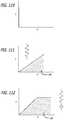
- the simplest embodiment of the present inventionincorporates a linear elastic spring.
- the energy absorption of the springcan be expressed as the product of force and displacement.
- non linear spring memberscan be employed to alter the energy absorption behavior under the same loading or displacement conditions.
- actual springsare used to show various embodiments of the present invention, these elements could also be substituted with a material or other device with spring-like characteristics (e.g., an elastomeric member).
- spring systemsmay be coupled with dampening devices such as dash pots.
- the spring elementis a storage or absorber device while the dashpot acts to dissipate the energy from the spring.
- dampening devicessuch as dash pots.
- the spring elementis a storage or absorber device while the dashpot acts to dissipate the energy from the spring.
- dampening devicese.g., a small pore sponge.
- One particular beneficial aspect of the energy absorption systems of the present inventionare that they are capable of absorbing a constant amount of energy from the joint independent of joint kinematics or loading conditions.
- the rigid body systems of the prior artare based on the physician separating (i.e., distracting) the natural joint a given distance in the unloaded state and attaching the rigid body system. The rigid body system then maintains this distance/distraction throughout the gait cycle and through bending of the joint. To maintain this distraction, the rigid body must transfer a wide range of forces directly depending on joint kinematics.
- the absorption systemmay be designed to absorb, dissipate and/or transfer energy at different rates or positions in the gait cycle thereby enabling customization of the system to the specific need.
- the absorption systemmay be designed to absorb severe sudden impact loads (such as jumping) and dissipate these loads after the impact event. This mode of operation is akin to the natural role of cartilage.
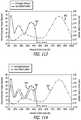
- the systemcan be designed to behave primarily as an energy transfer unit during high rates of knee motion (e.g. sprinting/running) but act as an energy absorber during normal rates of motion (e.g. walking).
- the absorption systemmay also be tuned to occur at particular points in the gait or flexion cycle depending on the disease state. For example an individual with concentrated loading at heel strike may only require absorption at this phase of knee motion so the system may be adjusted to act only during this region of the gait cycle. Alternatively an individual may have focal loss of cartilage on the posterior aspect of the femoral condyle and so stair climbing or kneeling becomes painful or problematic. In this scenario the system would be adjusted to absorb energy in the kinematic positions necessary and thereby maintaining the normal knee energy transfer outside of supporting the diseased locations.
- components of the systemare designed for easy removal and, if necessary, replacement while others are intended for permanent fixation.
- the permanent componentsare fixation attachment structures which can have bony ingrowth promoting surfaces and are responsible for fixation of the system to the skeletal structure.
- the removable componentsinclude the mobile elements of the system such as the link members and/or the pivots or ball joints.
- Various joints of the bodycan be treated employing the systems and methods of the present invention.
- articulating bones involved in synovial jointscan benefit from the present invention.
- the present inventioncan have applications in treating cartilaginous joints such as those found in the spine.
- the present inventionseeks to accomplish 1 to 40% energy or load reduction while maintaining full motion of the body parts.
- a 5 to 20% energy or load reductionhas been postulated to be desirable in certain circumstances to accomplish the alleviation of pain without approaching undesirable load shielding.
- the devices of the present inventionfurther provide greater energy manipulation during junctures of highest loads placed between body parts as well as less energy manipulation when loads between members decrease. In this way, the present invention complements the action of body parts such as those found at joints.
- jointsit is desirable that 100% of the energy be absorbed by the device(s), such joints may be those in the hands or upper extremity. In such cases, it may be desirable to have the devices placed bilaterally on either side of the joint. In the lower extremity, in severe cases, 100% energy absorption is achievable, however this may expose the device to more wear and shorter life. Some patients may accept this if the device is able to bridge the patient through a difficult period and it is easily replaced or removed without impacting the patients ability to receive a total joint replacement later.
- an energy absorption deviceis implanted at a diseased joint to restore cyclic, physiological-like loading thereby protecting chondrocytes from load induced apoptosis.
- an energy absorption deviceis implanted at a diseased joint to facilitate at least a partial recovery of morphological and ultra-structural aspects in osteoarthritic articular chondrocytes.
- an energy absorption deviceis implanted adjunctively with a cartilage repair procedure such as mosaicplasty, osteochondral allograft transfer, autologous chondrocyte implantation or microfracture.
- a cartilage repair proceduresuch as mosaicplasty, osteochondral allograft transfer, autologous chondrocyte implantation or microfracture.
- an energy absorption deviceis implanted in conjunction with a uni-compartmental joint replacement prosthesis or total joint replacement prosthesis. Such combination procedure will reduce wear rates by reducing the loads and contact forces between surfaces of the joint prosthesis.
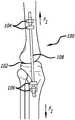
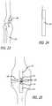
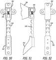
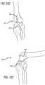
- the present inventionis embodied in a device utilizing an element, or elements functioning as a unit, which responds to bending or changes in elongation.
- this deviceforms a bending spring that is to span the tibiofemoral joint and be anchored into the tibia and femur.
- the deviceis used to take on some of the loading experienced by the articular surfaces of the tibiofemoral joint, thus unloading the joint.
- the deviceis designed to off load the joint during knee extension. Unloading in this phase is governed by the compression of the device—increased compression yields increased joint un-loading.
- the deviceis anchored in a position which ensures device elongation resulting from knee flexion. As the knee moves into flexion, the device is un-compressed and will cause little to no joint off-loading.
- the devicemay have other features which ensure correct device alignment, and prevent against buckling, as the device transitions into a compressed state.
- the devicecan also be configured to provide off-loading during flexion.
- the present inventionis embodied in a cam engagement assembly utilizing contacting elements, at least one of which having an eccentric contacting surface.
- the element, or elements, possessing the eccentric surfacedefine a cam.
- one elementis anchored to the femur and the other to the tibia.
- Implantedthe device will span the tibiofemoral joint.
- the degree, duration, and instance of elemental contactis dictated by the profile of the cam element or elements.
- the camis designed to cause increased contact stress between the device elements which span the joint when the knee is in extension.
- the normal energy experienced by the articular surfaces of the tibiofemoral jointwill be absorbed and taken on, in part, by the device.
- the cam profilewill ensure little or no engagement leading to joint off-loading.
- the amount of energy absorptionwill be controlled by a spring element which backs the cam element.
- the spring elementcan be adjusted, or exchanged, to tune the amount of energy absorption across the joint.
- a segmented support assemblyis employed to address joint needs.
- This conceptutilizes multiple elements that align to provide columnar support at desired phases of knee movement.
- the deviceis designed to provide columnar support during phases of knee extension. That is, each element is constrained by the adjacent element in a variable fashion—least constrained during states of elongation and most constrained during states of compression.
- the variable motion constraint, or tolerance which increases with elongationis designed so that the cumulative effect is to accommodate the complex motion of the tibiofemoral joint for example as it transitions from extension into flexion.
- the deviceis anchored, via mounting components, in a way that dictates device elongation during knee flexion and device compression during knee extension.
- the devicewill experience part of the energy normally taken on by the articular surfaces of the tibiofemoral joint—thus reducing the energy absorbed by the joint by a desired amount.
- the amount of energy absorptioncan be adjusted, via the mounting components, to a desired and measurable amount.
- the assemblywill accommodate the transition from an unloaded to a loaded state by the use of elements, possessing either spring or dampening characteristics, either in the device mounting components or in between the mating surfaces of the device elements.
- the inventionis embodied in a piston support assembly.
- This approachemploys a spring loaded piston mechanism to absorb energy normally experienced by the anatomical joint.
- the pistonis comprised of an axially mobile member or rod moving in a defined path.
- a compressible springis engaged thereby transferring load through the mechanism.
- the devicemay utilize rigid and coaxial elements that ride into or through each other. Load transfer and energy absorption occurs when the spring is engaged.
- the fixation points between bone and piston mechanismare free to revolve about an axis (possibly multiple axes).
- the pistonis capable of rotating about its longitudinal axis to facilitate rotational along the axis of the anatomical joint.
- the present inventionalso includes a staged procedure.
- the energy absorption systemis comprised of permanent fixation attachment structures and removable links.
- the permanent fixation attachment structuresincorporate a bone ingrowth promoter on their bone contacting surface (e.g. porous surface, calcium phosphate coating, textured surface etc.). It is important to stimulate this interface using moderate loads to ensure the creation of a bony interface, however overloading the interface prematurely may prevent bone ingrowth.
- a bone ingrowth promotere.g. porous surface, calcium phosphate coating, textured surface etc.
- the present inventionalso contemplates intra-articular drug delivery in combination with joint energy and load manipulation.
- a drug release deviceis loaded with a drug and a sustained released drug carrier, and placed at a target area within or near a diseased or malaligned joint, such as on or in the device of the present invention.
- Various drugs and mechanisms for sustained releaseare also contemplated.
- the present inventionalso contemplates employing sensors to provide information on performance.
- pressure sensorscan be placed within or adjacent the device or anatomy to indicate aspects of function and loads. Sensors in the implant may allow for non-invasive telemetry and capture of information regarding joint motion. Telemetry may be usable to control various settings in the device.
- the present inventionalso contemplates that the components are compatible with joint diagnostic techniques such as magnetic resonance imaging and computed tomography.
- the present inventioncontemplates post-operative percutaneous adjustability and tuning of the implant's characteristics in response to patient feedback. It may be desirable to detect the internal tension and/or dampening setting of the device while it is being accessed percutaneously or alternatively have those features easily detectable using x-ray or another non-invasive modality such as ultrasound.
- Another aspect of some embodiments of the present inventionis to enclose at least a part of the energy manipulating device in a sheath.
- the sheathallows the tendons and soft tissue to avoid being abraded by the presence of the implant in that region during movement. By allowing the tissue to form a capsule around the sheath of the implant, the tissue will be strengthened and the likelihood of erosion will be reduced.
- the sheathalso allows for easy replaceability, in some embodiments, of the link components because they can be inserted into the sheath once the original components are removed without causing any additional tissue disruption.
- FIG. 1is a side view, depicting a energy manipulation assembly of the present invention
- FIG. 2is a side view, depicting the assembly of FIG. 1 after articulation of body members;
- FIG. 3is a front view, depicting a bilateral (or lateral and medial) application of a lower manipulation assembly of the present invention
- FIG. 4is a side view, depicting a bending spring energy manipulation assembly of the present invention
- FIG. 5is a side view, depicting the assembly of FIG. 4 after articulation of body members
- FIG. 6is a front view, depicting the energy manipulation assembly of FIG. 4 ;
- FIG. 7is a side view, depicting a energy manipulation assembly including a pair of springs
- FIG. 8is a side view, depicting the assembly of FIG. 7 after articulation of body members
- FIG. 9is a perspective view, depicting a bending spring energy manipulation assembly including a guide shaft
- FIG. 10is a side view, depicting a energy manipulation assembly including locking structure
- FIG. 11is a side view, depicting an energy absorbing spring assembly including undulations configured along a helical path;
- FIG. 12is a perspective view, depicting a energy manipulation assembly including load bearing members and a central spring;
- FIG. 13is a perspective view, depicting another embodiment of a bending spring assembly with a midsection spring
- FIG. 14is a front view, depicting yet another energy manipulation assembly including a central spring
- FIG. 15is a perspective view, depicting a yet further bending spring assembly with a central spring
- FIG. 16is a perspective view, depicting a bending spring assembly including a stop member
- FIG. 17is a perspective view, depicting the bending spring assembly of FIG. 16 in its compressed configuration
- FIG. 18is a perspective view, depicting adjustable attachment structure of a energy manipulation assembly
- FIG. 19is a partial cross-sectional view, depicting dampening structure of an attachment assembly
- FIG. 20is a perspective view, depicting another embodiment of an attachment structure of a load bearing member
- FIG. 21is a cross-sectional view, depicting mounting structure formed in body anatomy
- FIG. 22is a partial cross-sectional view, depicting a energy manipulation assembly affixed to the body anatomy shown in FIG. 21 ;
- FIG. 23is a cross-sectional view, depicting a load bearing assembly contained substantially entirely within body anatomy
- FIG. 24is a side view, depicting an enlarged view of the energy manipulation assembly shown in FIG. 23 ;
- FIG. 25is a side view, depicting a bending spring energy manipulation assembly including a slot for articulating movement
- FIG. 26is a side view, depicting another embodiment of a bending spring assembly including pivoting structure
- FIG. 27is a side view, depicting yet a further embodiment of a bending spring assembly including pivoting structure
- FIG. 28is a perspective view, depicting a energy manipulation assembly incorporating cam engagement structure
- FIG. 29is a side view, depicting the load bearing assembly shown in FIG. 28 ;
- FIG. 30is a perspective view, depicting yet another embodiment of a energy manipulation assembly
- FIG. 31is a perspective view, depicting a energy manipulation assembly including multiple camming surfaces
- FIG. 32is a front view, depicting a energy manipulation assembly including camming surfaces and spring biasing structure;
- FIG. 33is a perspective view, depicting yet another embodiment of a energy manipulation assembly including multiple camming surfaces
- FIG. 34is a front view, depicting a energy manipulation assembly including camming surfaces and pivoting substructure;
- FIG. 35is a partial cross-sectional view, depicting a ball bearing in combination with camming surfaces
- FIG. 36is a side view, depicting a energy manipulation assembly employing a ball-like camming surface
- FIG. 37is a side view, depicting the assembly of FIG. 37 in relation to articulated body members;
- FIG. 38is a front view, depicting a energy manipulation assembly incorporating segmented support substructure
- FIG. 39is a side view, depicting the assembly shown in FIG. 38 further incorporating a slotted engagement arrangement
- FIG. 40is a perspective view, depicting another embodiment of a segmented support subassembly
- FIG. 41is a perspective view, depicting yet another embodiment of a segmented support subassembly
- FIG. 42is a perspective view, depicting yet still another segmented support subassembly
- FIG. 43is a side view, depicting members forming a segmented support subassembly
- FIG. 44is a perspective view, depicting disengaged members of a segmented support subassembly
- FIG. 45is a perspective view, depicting a segmented support assembly encased in an outer sheath
- FIG. 46is a perspective view, depicting both a longitudinally arranged segmented support assembly and its configuration upon bending;
- FIG. 47is a perspective view, depicting a segmented support assembly including variable interlocking links in combination with spring assemblies;
- FIG. 48is a side view, depicting yet another embodiment of a segmented energy manipulation assembly
- FIG. 49is a side view, depicting still yet another embodiment of a segmented energy manipulation assembly
- FIG. 50is a partial cross-sectional side view, depicting still yet another segmented support assembly for a energy manipulation assembly
- FIG. 51is a partial cross-sectional view, depicting the assembly of FIG. 50 ;
- FIG. 52is a bottom view, depicting the assembly shown in FIG. 50 ;
- FIG. 53is a side view, depicting a segmented energy manipulation assembly including slotted attachment structure
- FIG. 54is a side view, depicting a modification to the assembly shown in FIG. 53 ;
- FIG. 55is a front view, depicting a energy manipulation assembly incorporating segmented and articulating structure
- FIG. 56is a side view, depicting sheathing of members of a energy manipulation assembly
- FIG. 57is a perspective view, depicting further aspects of a segmented support assembly of the present invention.
- FIG. 58is a side view, depicting yet further aspects of segmented support assemblies of the present invention.
- FIG. 59is a side view, depicting a energy manipulation assembly including articulating and segmented structure
- FIG. 60is a front view, depicting a energy manipulation assembly incorporating piston support
- FIG. 61is a side view, depicting the assembly of FIG. 60 after articulation of body members
- FIG. 62is a front view, depicting another embodiment of a energy manipulation assembly incorporating piston support
- FIG. 63is a cross-sectional view, depicting substructure of the assembly shown in FIG. 62 ;
- FIG. 64is a partial cross-sectional view, depicting another embodiment of a piston support subassembly
- FIG. 65is a partial cross-sectional view, depicting yet another embodiment of a piston support subassembly
- FIG. 66is a perspective view, depicting still yet another embodiment of a piston support subassembly
- FIG. 67is a perspective view, depicting the assembly of FIG. 66 in a compressed configuration
- FIG. 68is a perspective view, depicting a further embodiment of a energy manipulation assembly incorporating piston support structure
- FIG. 69is a perspective view, depicting a telescoping arrangement of a piston support subassembly
- FIG. 70is a perspective view, depicting the assembly of FIG. 69 in a compressed configuration
- FIG. 71is a cross-sectional view, depicting a energy manipulation assembly substantially completely imbedded within body tissue
- FIG. 72is a cross-sectional view, depicting another approach to a energy manipulation assembly substantially completely imbedded within body tissue
- FIG. 73is a cross-sectional view, depicting a first step in the implantation of a energy manipulation assembly incorporating piston support;
- FIG. 74is a cross-sectional view, depicting a second step in the implantation of the assembly shown in FIG. 73 ;
- FIG. 75is a perspective view, depicting a load bearing member of a energy manipulation assembly including piston support and incorporating rotational substructure;
- FIG. 76is a perspective view, depicting adjustment substructure of a energy manipulation assembly for the present invention.
- FIG. 77is a cross-sectional view, depicting further aspects of the assembly depicted in FIG. 76 ;
- FIG. 78is a perspective view, depicting further aspects which can be incorporated into the assembly depicted in FIG. 76 ;
- FIG. 79is a perspective view, depicting adjustment structure of a energy manipulation assembly of the present invention.
- FIG. 80is a cross-sectional view, depicting a first step in the implantation of a sheathed energy manipulation assembly
- FIG. 81is a cross-sectional view, depicting a second step in an implantation approach of the assembly depicted in FIG. 80 ;
- FIG. 82is a cross-sectional view, depicting the assembly of FIG. 81 fully implanted
- FIG. 83is a cross-sectional view, depicting an enlarged view of an implanted energy manipulation assembly including piston support;
- FIG. 84is a cross-sectional view, depicting an alternate embodiment of a energy manipulation assembly incorporating piston support implanted within body anatomy;
- FIG. 85is a cross-sectional view, depicting further substructure which may be incorporated into the assembly depicted in FIG. 84 ;
- FIG. 86is a cross-sectional view, depicting another embodiment of a energy manipulation assembly of the present invention incorporating piston support substructure;
- FIG. 87is a perspective view, depicting a energy manipulation assembly including lateral substructure spanning a width of treated body tissue;
- FIG. 88is an enlarged view, depicting substructure of the device depicted in FIG. 87 ;
- FIG. 89is an enlarged view, depicting substructure of the device depicted in FIG. 87 ;
- FIG. 90is a cross-sectional front view, depicting the assembly of FIG. 87 ;
- FIG. 91is a cross-sectional view, depicting yet another component of the assembly depicting in FIG. 87 ;
- FIG. 92is a perspective view, depicting a further embodiment of a energy manipulation assembly incorporating piston support
- FIG. 93is a cross-sectional view, depicting substructure of the assembly depicted in FIG. 92 ;
- FIG. 94is a cross-sectional view, depicting other substructure of the assembly depicted in FIG. 92 ;
- FIG. 95is a back view, depicting yet another approach for an energy manipulation assembly
- FIG. 96is a perspective view, depicting the approach shown in FIG. 95 ;
- FIG. 97is a side view, depicting a further embodiment of an energy manipulation assembly of the present invention.
- FIG. 98is a perspective view, depicting a bilateral approach of the present invention.
- FIG. 99is a perspective view, depicting another bilateral approach of the present invention.
- FIG. 100is a perspective view, depicting an embodiment of the present invention where the body anatomy is aligned
- FIG. 101is a perspective view, depicting the embodiment of FIG. 100 with the body anatomy in an articulated configuration
- FIG. 102is a perspective view, depicting an embodiment of the present invention incorporating pivoting and disengaging structure
- FIG. 103is a perspective view, depicting the embodiment of FIG. 102 with the anatomy in an articulated position;
- FIG. 104is a perspective view, depicting yet another embodiment of mounting structures attached to body anatomy
- FIG. 105is a perspective view, depicting still yet another embodiment of mounting structure attached to body anatomy
- FIG. 106is a perspective view, depicting yet another approach to an energy manipulation assembly
- FIG. 107is a side view, depicting the normal forces existing in a joint
- FIG. 108is a side view, depicting the present invention incorporated into the joint shown in FIG. 108 ;
- FIG. 109is a side view, depicting the effect an energy manipulating assembly of the present invention has on the joint shown in FIGS. 107 and 108 ;
- FIG. 110is a graph, illustrating the energy characteristics of a prior art rigid structure applied across a joint
- FIG. 111is a graph, illustrating the energy characteristics of a linear spring system of the present invention.
- FIG. 112is a graph, illustrating the energy characteristics of a spring and dampening system of the present invention.
- FIG. 113is a graph, illustrating the flexion/extension angle and joint force existing in a gait cycle
- FIG. 114is a graph, illustrating one approach to energy absorption on a gait cycle
- FIG. 115is a graph, illustrating a second approach to energy absorption on a gait cycle
- FIG. 116is a graph, illustrating a third approach to energy absorption on a gait cycle
- FIG. 117is a graph, illustrating a fourth approach to energy absorption on a gait cycle
- FIG. 118is an isometric view, depicting another energy manipulation assembly of the present invention.
- FIG. 119is a perspective view, depicting the application of the present invention to another body joint
- FIG. 120is an enlarged view, depicting the energy manipulation assembly of FIG. 119 ;
- FIG. 121is a side view, depicting the application of the present invention to a foot joint
- FIG. 122is a top view, depicting the application of the present invention to a finger joint
- FIG. 123is a side view, depicting an alternate to the approach shown in FIG. 122 ;
- FIG. 124is a perspective view, depicting the application of the present invention to a spinal joint.
- FIG. 125is a perspective view, depicting another application of the present invention to a spinal joint.
- the present inventionis directed towards apparatus and methods for treating body tissues.
- the present inventionseeks to alleviate pain associated with the function of diseased or malaligned members forming a body joint.
- the present inventionis particularly suited to address issues associated with osteoarthritis, the energy manipulation accomplished by the present invention lends itself well to broader applications.
- the present inventionis particularly suited to treating synovial joints such as the knee and shoulder.
- the apparatus and method of the present inventioncan be employed to treat the spine facet joints and spine vertebral joints as well as other synovial and various other joints of the body such as those of the hand and feet.
- the present inventionseeks to permit and complement the unique articulating motion of the members defining a body joint of a patient while simultaneously manipulating energy being experienced by both cartilage and osseous tissue (cancellous and cortical bone).
- Approaches involving varying energy absorption and transfer during the pivoting of the joint and selecting a geometry for the energy absorption assembly to provide necessary flexibilityare implemented into various embodiments of the present invention.
- Certain of the embodimentsinclude geometry which accomplishes variable energy absorption designed to minimize and complement the dampening effect and energy absorption provided by the anatomy of the body, such as that found at a body joint. It has been postulated that to minimize pain, off-loading or absorption of 1-40% of forces, in varying degrees, may be necessary. Variable off-loading or absorption in the range of 5-20% can be a target for certain applications. In certain specific applications, distraction is employed in the energy manipulation approach.
- a bending spring assemblyis contemplated to manipulate or absorb forces between body parts.
- an assembly utilizing an element or elements which respond to bending or changes in elongationmay be desirable to treat afflictions such as osteoarthritis.
- Certain of the assembliescan incorporate features which insure correct device alignment and prevent against buckling as the member transitions between compressed and uncompressed states.
- a bending spring assembly 100can be configured along members forming a body joint 102 .
- the bending spring assembly 100includes one or more attachment structures 104 , 106 and a energy absorbing member 108 .
- the attachment structures 104 , 106are anchored to the members or bones forming the body joint 102 .
- the energy absorbing member 108is in the form of a bending spring and is attached to each of the attachment structures 104 , 106 . While the members defining the joint 102 are generally longitudinally arranged, the energy absorbing member 108 absorbs and/or transfers forces being bared by the members of the joint. In a simplified approach, the energy absorbing member 108 can also apply lateral forces to the member of the joint 102 during flexion.
- a bending spring assemblycan be affixed to either a lateral or medial side of a body joint 102 .
- bending spring assembliescan additionally be placed on both lateral and medial (or bilateral) surfaces of a body joint 102 .
- the energy manipulation achieved by a system of a plurality of bending spring assemblies 100can be configured to provide different energy manipulation on opposing sides of a joint 100 to thereby accomplish a more complex energy absorption curve and where desired variable off-loading, while permitting and complementing the unique path of motion of the members of a joint of a particular patient.
- a energy absorbing assembly including an undulating spring member 110 having a variable pathcan be attached to members defining a body joint 102 .
- the variability of the pathis selected to provide additional dampening and/or energy absorption to thus off-load one or more of the cartilage or osseous bones of the joint.
- the energy absorbing spring assembly 110can be configured to provide such energy manipulation during extension and to become less active during flexion of the members of a joint 102 .
- the bending spring assembly 112includes a pair of springs attached on the same side of a body joint 102 .
- the springscan provide energy manipulation in both flexion and in extension.
- the compressed springprovides central off-loading in a direction normal to joint structure and the extended spring is uncompressed so as to not distract a posterior section of the joint.
- the posterior springprovides energy manipulation normal to the direction of the lateral member of the joint while the centrally located spring provides no off-loading.
- Other combinations of bend spring assemblies 112are further contemplated to accomplish other energy manipulation scenarios which may be useful in minimizing joint pain.
- the bending spring assembly 114includes a helical spring 116 configured about a guiding member 118 .
- the helical spring 116is further configured between anchor points 120 which are affixed to a patient's anatomy. As the members defining a body joint articulate, the anchor points 120 move with respect to each other, the guiding member 118 providing a controlled path for the spring 116 and the spring 116 thereby provides the desired energy absorption and/or load transfer.
- a helical spring 122 of a bending spring assemblycan include interlocking structure 124 which alters the function of the spring 122 .
- the interlocking structurecan be adapted to prevent rotation of the spring 122 at a predetermined amount of compression or extension of the spring 122 .
- a variable energy manipulationcan be provided by this structure.
- such structurecan alternatively or additionally be employed to prevent or control joint rotation at a given degree of extension or flexion.
- a spring assembly 126 having an overall helical configurationis depicted in FIG. 11 .
- This spring assembly 126further includes undulations 128 configured along the general helical framework as well as sections with varying thickness.
- the spring assembly 126can provide a varying energy absorption profile which matches the needs of a particular body joint, providing energy manipulation during certain pre-determined phases of articulation of members defining the joint.
- a spring assemblycan include spring portions divided by a center section including an elastomeric sleeve (not shown) which provides the device with desired energy manipulation characteristics.
- the elastomeric sleevecan be used in affixing the assembly at the joint requiring treatment.
- a mid-section of the bending spring assemblyincludes a spring member 136 .
- Opposing ends of the assemblyinclude bone anchors 138 .
- the opposing endscan include one or more attachment structures or bone anchors 138 .
- Configured between the bone anchor structure 138 and on opposing sides of the central spring 136are load transfer beams 140 .
- the load transfer beams 140can be made to rotate with respect to the bone anchors 138 and each other.
- the bending spring assembly 142 depicted in FIG. 15also includes a centrally located spring 144 configured between a pair of load transfer beams 146 .
- the spring 144can assume various profiles characterized by varying widths and pitches to thereby provide the desired energy manipulation profile.
- FIGS. 16 and 17depict yet another embodiment of a bending spring assembly 148 .
- the energyis absorbed initially by an undulating beam 150 .
- curved portions thereofengage a centrally located stop member 152 .
- the stop member 152can be formed of rigid or non-rigid material depending on the energy manipulation that is desired in the application at hand.
- a rod 154 connected to one such bend spring assemblycan be coupled to a bracket assembly 156 which is affixed to body anatomy of a patient.
- a bracket assembly 156which is affixed to body anatomy of a patient.
- the bracket assembly 156can further or alternatively include a spring 158 ( FIG. 19 ), the tension of which can be adjusted percutaneously to provide desired dampening or shock absorption at the ends of a bending spring assembly.
- the bracket assembly 156 for these any of the disclosed embodimentscan further include a textured surface 160 adapted for attachment to patient anatomy. Such texturing can surface irregularities or can come in the form of materials adapted for tissue in-growth.
- the bending spring assemblies and for that matter each of the disclosed embodiments of energy manipulation assembliescan be attached to body anatomy in various ways.
- the assemblies of the present inventioncan be surface mounted upon anatomy by employing anchors.
- mounting structure 162can be inserted completely or partially within bones 163 , for example, such as that in the manner depicted in FIGS. 21 and 22 . Further anchoring of the assemblies can occur through a surface of the bone (See FIG. 22 ).
- a energy manipulation assembly 164can be placed substantially entirely with a bone 163 , leaving a terminal end thereof to accomplish desired energy transfer and/or absorption.
- the bending spring assembliescan embody rather complex structures. As shown in FIG. 25 , one contemplated bend spring assembly 166 including a spring 168 can be attached to a pair of spaced attachment structures 170 , 172 . Such attachment structures 170 , 172 can be directly connected to body anatomy or can be further attached to structure mounted on or within anatomy.
- the spring 168includes one end which is fixed or rotatably connected to a first attachment structure 170 and a second end is constrained within a curved slot formed in the second attachment structure 172 . Again, this unique design is contemplated to provide a body joint or other anatomy with a desired energy absorption and/or transfer profile which complements the unique articulation at the target tissue.
- the spring 168 of a bending spring assembly 166can likewise be configured between one or more pivoting attachment structures 170 , 172 (See FIGS. 26, 27 ).
- one or both of the attachment structures 170 , 172are allowed to pivot about a pivot point.
- the pivoting action of the attachment structures 170 , 172 of the device of FIG. 27are constrained by stops 174 .
- sensing mechanismsadapted to provide loading information concerning the tissues being treated.
- the various pressured sensing mechanisms availablecan be placed upon the devices of the present invention.
- Such sensorscan be configured to provide information about the efficacy of the energy manipulating device of the present invention and whether adjustments are necessary.
- sensorscan be placed on anatomy to provide information regarding loads being placed on the tissues themselves.
- drugscan be delivered to the interventional site targeted for energy manipulation.
- the entirety of the subject matter disclosed in U.S. Publication No. 2007/0053963is hereby incorporated by reference.
- the present inventionis embodied in a cam engagement assembly for energy manipulation.
- the cam engagement assemblyemploys contacting elements, at least one of which has an eccentric contracting surface.
- the degree, duration and instance of elemental contactis controlled by the profile of the cam element or elements. Increased contact stress is contemplated between device elements when the body anatomy members are in extension.
- the cam profilecan be configured to ensure little or no engagement.
- the assemblycan include a spring assembly that can be made to be adjusted, or exchanged, to tune the amount of energy absorption across anatomy.
- the surface engagement of the devicecan be created through multiple methods and can include such structure as wear-resistant bearing surfaces, ball bearings at a surface engagement site or a geared engagement.
- the mounting features of the devicecan be contained in separate mounting elements or incorporated into anatomy spring elements. The mounting design can further accommodate complex motion of a joint as it transitions from extension to flexion by allowing for rotation and pivoting, or through the use of compressible materials.
- FIGS. 28-37Various approaches to cam related energy manipulation are depicted in FIGS. 28-37 .
- curved load bearing surfaces 202are configured to rotate with respect to each other.
- the load bearing surfaces 202are connected to attachment structure 204 , 206 which in turn are affixed to body anatomy such as bones forming a joint.
- the connections between the load bearing surfaces 202 and attachment structures 204 , 206 or between the attachment structures 204 , 206 and the bonecan be spring loaded or otherwise be comprised of flexible or elastic materials.
- the energy bearing surfaces 202move between varying degrees of engagement.
- the greatest off-loading and energy manipulationoccurs between loading members 202 when the body anatomy is in its extension configuration.
- the varying degrees of engagementare pre-selected to absorb energy between body members with the aim of reducing or eliminating pain. In this way, unique paths of motion can be preserved during an attempt at absorbing energy.
- FIG. 30Another embodiment of a cam engagement assembly is shown in FIG. 30 .
- a center load bearing, joint section 208is configured between a pair of spaced attachment brackets 210 .
- Post members 212provide rotation points to define an articulating engagement assembly.
- Various connecting points 214can be further provided along the attachment bracket 210 to receive the post members 212 to thereby provide a means to readjust the assembly to fit a patient's needs.
- gearing structurecan be implemented into this embodiment to provide desired control between moving parts.
- FIGS. 31 and 32Another embodiment of a cam engagement assembly 215 of the present invention is depicted in FIGS. 31 and 32 .
- camming surfaces 216are adapted to fit the natural contour of the body anatomy.
- the camming surfaces 216are provided along substantially an entire range of surfaces of natural tissue which may come into contact.
- This structureis supplemented with a energy absorbing assembly 218 comprising springs or other structure for absorbing energy from areas of contact between the camming surfaces 216 .
- Such an assembly 215is affixed at a joint or other body anatomy employing approaches described herein.
- FIG. 33there is shown a cam engagement assembly 220 including a first concave camming surface 222 and a second convex camming surface 224 . These surfaces are biased apart by a pair of springs 226 arranged in a parallel fashion. Each of the camming surfaces 222 , 224 include cavities for receiving a portion of the springs 226 .
- the springs 226act as a energy absorbing structure and in combination with the convex and concave surfaces 222 , 224 complements the action of the body parts to which the assembly is attached.
- FIG. 34A similar combination of elements is disclosed in FIG. 34 .
- the camming surface assemblies 230are at least at one end attached in a spring loaded arrangement 233 to brackets 232 .
- a second camming surface 230can be connected in a manner to allow pivoting between the camming surface 230 assembly and bracket 232 such as by providing a slotted connector 236 .
- the brackets 232are in turn affixed to body anatomy.
- Configured between the camming surface assemblies 230is a load bearing spring assembly 238 which at opposing ends engages receiving holes formed in the camming surface assemblies 230 .
- a ball bearing 240can be strategically placed between camming surfaces 242 of a cam engagement assembly for the purpose of aiding the relative motion between the structures. Such an approach can be further incorporated into any of the disclosed assemblies.
- a ball bearing 240is placed between the anatomy of articulating members of a patient.
- a disccan be employed in like fashion.
- the ball bearing structure 240is supported by energy absorbing springs 242 which are in turn attached to attachment structure 246 mounted to patient anatomy.
- a further aspect of the present inventionis embodied in a segmented support assembly.
- this approachemploys multiple elements that align and mate to provide column support as desired, such as during extension of loading parts.
- adjacent elements forming a segmented support assemblycan be constrained by an adjacent element in a variable fashion to accommodate the complex motion of articulating members. The amount of energy manipulation is adjusted by mounting or attaching components via spring or dampening assemblies.
- Fixation attachment structures 302are provided to attach the assembly to patient anatomy.
- Medially positioned pivot points 304 in combination with adjustable spacers 306define a segmented load bearing member and provide desired off-loading as well as multi-dimensional flexibility permitting the patient anatomy to articulate freely.
- the spacers 306function to facilitate alignment.
- at least one fixation attachment structure 302can include a slotted receiving trough 306 sized to receive one terminal end 308 of the segmented load bearing member, the terminal end 308 slideably engaging the slot.
- the segmented load bearing membercan assume various shapes and forms. These approaches incorporate multiple, mating elements which provide columnar support while facilitating multi-dimensional movement. Such approaches are shown in FIGS. 40-45 . As depicted in FIG. 40 , disc-like members 310 are connected in a series via interconnecting structures 312 contemplated to permit three-dimensional translation between adjacently arranged discs 310 . While three-dimensional motion is contemplated, the degree of motion is constrained by the members defining the segmented load bearing member. Accordingly, there can be limited axial compression of the members so that there is a desired amount of columnar support. Likewise, lateral pivoting of the members is limited by the geometry of the adjacent discs. The lateral pivoting can be selected to permit and complement the unique articulation of a particular patient's anatomy.
- the structure defining a segmented load bearing membercan assume relatively complex geometry. That is, various embodiments of interlocking links 314 can form a segmented load bearing member 316 (See FIGS. 41-46 ). Such links 314 can be held within a sheath 318 ( FIGS. 41 and 45 ) or can be locked together to permit articulation without the need for an outer sheath ( FIGS. 42-44 and 46 ). In a further aspect (See FIG. 46 for example), certain designs of the links 314 can include a projection 320 , a number of which are received within a variable shaped slot 322 of an adjacent link. The variable staged slot 322 can further include a narrower section 324 which is sized and shaped to engage the projection 320 in a manner to both absorb loads as well as constrain articulating motion.
- the links 314 of a segmented section of a load bearing member 316can embody variably shaped links 314 . That is, the geometry of the links 314 can vary along a length of a load bearing member 316 to thereby provide differing articulation at various points.
- the assemblycan incorporate one or more springs 326 designed to facilitate desired energy absorption and/or dampening.
- FIGS. 48-52Other examples of assemblies including segmented load sharing linkages in combination with spring assemblies are shown in FIGS. 48-52 .
- springs 326can be placed at one or more ends of the segmented load bearing members 316 . It may be convenient to configure the springs 320 within attachment structures 302 employed to anchor the assembly to body anatomy. Springs 320 can also be placed along other portions of the assembly to achieve desired effects.
- the assemblyis provided with slotted structure 330 rather than springs.
- the slotted structure 330can be configured within the attachment structure 302 and be both generally vertical ( FIG. 53 ) or generally horizontal ( FIG. 54 ).
- An adjustment screw 332 or similar structurecan further be provided to permit adjustment of the attachment structure relative to patient anatomy and to the segmented load bearing structure 316 .
- segmented support assemblies of the present inventionemploy articulating linkages rather than interlocking links to provide desired results (See FIGS. 55-59 ).
- the various contemplated articulate linkages 334can have a myriad of shapes and sizes and can include one or more points of articulation 336 .
- Opposed ends of the linkages 334are affixed to body anatomy in varying ways as well.
- mounting structure of one approachcan be substituted for another and thus, the load bearing assemblies can be surface mounted to anatomy or partially buried therewithin.
- the linkagescan be sheathed (See FIG. 56 ) or can lack sheathing.
- the present inventionemploys piston support to accomplish desired load manipulation.
- these embodimentsinclude an axially mobile member which translates in a defined linear path.
- a compressible springcan be included to facilitate energy absorption and transfer and the assembly can further include structure permitting articulation between the piston subassembly and the body anatomy.
- FIGS. 60 and 61A simplified approach involving a piston support, load manipulation assembly 400 is depicted in FIGS. 60 and 61 .
- the piston member 402is highly laterally flexible but also sufficiently longitudinally rigid to thereby both bend with the articulation of body members as well as absorb compression forces when the body members are in extension.
- One or more cylinders 404are configured to accept longitudinal translation of the piston 402 .
- a piston support assembly 400can further include springs 406 to aid in the load manipulation being sought (See FIGS. 62 and 63 ). Such springs 406 can be placed within an attachment cylinder 404 ( FIG. 63 ) or can be additionally or alternatively placed about the piston assembly 402 . Moreover, the piston assembly 402 can assume a complex geometry which includes both pivot points 408 and/or curvilinear portions 410 . As in all of the disclosed embodiments, the structure can be affixed to body anatomy so that it spans a joint between articulating members.
- FIGS. 64-70Further embodiments of piston-based load bearing members are disclosed in FIGS. 64-70 .
- FIG. 64discloses an arrangement when a spring 402 spans the length of the piston member 402 and within spaced cylinders 404 .
- FIG. 65employs a piston member 402 which additionally includes bending spring structures for energy manipulation.
- FIGS. 66 and 67depict a piston assembly 402 including a knurled outer surface and is further contemplated to include means for adjusting the strength of its loading capabilities by rotating the piston with respect to the cylinder.
- FIG. 68shows an assembly which includes a spring 406 configured about the piston 402 having a stepped profile and between a cylinder 404 and a pair of stops 412 . This assembly is also contemplated to be adjustable between high and low spring tensions.
- a piston support based assembly 400can also include a plurality of telescoping members 414 arranged longitudinally.
- certain of the circumferentially arranged telescoping membersact both as pistons and cylinders for adjacent structure.
- a desired energy absorbing profilecan be provided by the structure to thereby absorb energy in a desired sequence.
- the energy absorbing assemblies of the present inventioncan be surface mounted upon anatomy or can be inserted completely or partially within the target tissue.
- a piston based, energy manipulation assembly 400having one or more cylinders 404 receiving a piston 402 can be substantially completely implanted within a member defining a target tissue. The portions extending out from a surface of the tissue provide the energy absorbing characteristics needed for a particular application.
- the assemblies 400can also be configured to span articulating body members and include a portion of the cylinder 404 being buried within body tissue as shown in FIGS. 73 and 74 .
- the energy absorbing assembly 402includes a mid-section characterized by a piston having bending spring qualities and further includes collars 416 which are configured to rotate with respect to the piston.
- the collars 416are also sized and shaped to be placed into a reciprocating motion with a cylinder.
- the collars 416can further include a washer and bearing arrangement which permits rotation of the collar 416 and the piston or end 402 .
- a screw assemblycan be employed to connect the mid-section of the piston assembly with the collar 416 .
- a spring 422can be further provided within the collar 416 (See FIG. 77 ) to accept loads.
- the assembly 400is then threaded within an attachment structure 424 and affixed to or within body tissue.
- inner 430 and outer members 432 of the collar assembly 416can be adjustable post-implant.
- the collar assembly 416can include a percutaneously accessible adjustment screw 434 which controls the relative positions between the inner and outer members 430 , 432 .
- One or more of the inner and outer housings 430 , 432can alternatively be equipped with a gear surface 436 that is accessible by a percutaneous gear shaft tool 438 .
- the tool 438includes a terminal end 440 configured with a gear surface complementary to that of the gear surface formed on the collar assembly 416 . In this way, tension as well as spacing of the components of a energy manipulation assembly can be altered or corrected as needed.
- FIGS. 80-84A sheathed energy manipulation assembly 440 incorporating various aspects of the present invention is shown in FIGS. 80-84 .
- ends of the assemblyare reciprocally mounted within body tissue.
- the length of the deviceis encased in a sheath 442 .
- various of the contemplated energy manipulation assembliescan be encased to thereby provide smooth surfaces which are less traumatic to body tissue.
- one or more spring assemblies 444can be placed about and in apposition with load bearing structure.
- the piston-type bearing assemblycan further include an adjustment screw 450 arranged in a parallel fashion with respect to other energy absorbing structure to alter the effect of the same. Again, it is anticipated that such adjustment structure can be accessed percutaneously after the load bearing assembly is placed at or within a target tissue.
- FIG. 86Yet another embodiment of the present invention is disclosed in FIG. 86 .
- a pair of spaced attachment assemblies 460include projections 462 for engaging the tissue to be treated.
- the attachment assemblies 460further each include locking side screws 464 as well as a rotatable access screw head 465 which operate to affect a longitudinal position (advancement and retraction) of a threaded shaft with a ball-tipped terminal end 466 .
- Configured between the longitudinally spaced shafts 466is a piston and cylinder assembly 468 having opposed ends 470 with a socket sized to receive the ball portion of the threaded shaft 466 .
- a first spring 472is contained within the cylinder 474 of the assembly.
- a second spring 476is coaxially arranged about the threaded shafts 466 and piston and cylinder assembly 468 . Further, a sheath 476 is placed about these subassemblies from one attachment assembly to another 460 .
- this embodiment of a energy manipulation assemblyprovides both energy absorption as well as multi-dimensional translation to permit body anatomy articulation.
- a bi-lateral energy manipulation assembly 480includes a pair of laterally configured shafts 482 , at the terminal ends of which are connected a single energy absorbing member 484 .
- the energy absorbing member 484can include a piston and spring assembly arranged and the shafts can extend a full width and length of the tissue being treated.
- the laterally configured shafts 482can include a longitudinally extending trough 486 employed to selectively engage complementary surfaces of the energy absorbing member assemblies 484 .
- tissue inserts 488 in the form of collarsare contemplated to receive at least a portion of a length of the shafts 482 .
- Such inserts 488 as well as other surfaces of the various disclosed embodiments and approachescan include a bone-ingrowth coating or texture.
- FIG. 92A related unilateral mounted device is shown in FIG. 92 .
- the shafts 482extend less than a full width of the body anatomy but otherwise include a piston-based energy manipulation assembly 484 .
- the members defining the piston assembly 484can be sheathed with encasing structure 486 and can pivot about end points 488 .
- the encasing structure 486can be applied to various structures of the disclosed embodiments and can be formed from PTFE, ePTFE, Dacron, Polypropylene, Polyethylene, or woven materials such as silk.
- This structure 486can also be created from bioabsorbable material and can be drug loaded or impregnated with silver or other agents capable of stimulation or reducing inflammation.
- the piston subassemblycan further include a biasing spring 490 configured about a piston 492 and placed in a position with an internal cylindrical sleeve 494 .
- a further energy absorbing structure 496such as a simple bending, columnar spring or a conventional helical spring (See FIGS. 93 and 94 ).
- the piston subassembly 484can include a platform 498 , the position of which is adjustable by turning a central screw shaft 500 .
- the screw shaft 500be percutaneously accessed for ease of adjustment.
- the dampening elementcan also involve a fluid-dampening system ( FIGS. 93 and 94 ). Holes 502 formed in an end of position 492 effect a slow movement of fluid 504 through the assembly to prevent rapid changes in velocity.
- the energy absorbing substructure 496is engaged only at maximal compression of the assembly and at all other times remains free within the device.
- the energy manipulation assembly 510 shown in FIGS. 95 and 96includes first and second attachment structures 512 , 514 having contours selected to match outer surfaces of body anatomy.
- An energy absorbing member 516includes a pair of spaced ends each being pivotably attached to one attachment structure.
- the connection to the attachment structures 512 , 514 as well as the energy absorption member 516can further be sheathed in encasing structure 518 as described above. In this way, the overall structure assumes a low profile and generally atraumatic assembly which tends to cooperate with body anatomy.
- an energy manipulation assembly 520 of the present inventioncan incorporate into a first of a pair of attachment structures 522 , 524 for mounting to body anatomy, an energy manipulation subassembly 526 .
- the attachment structure 522includes a first end for mounting to body anatomy as well as a midsection employing a spring assembly 528 and a second end 530 including a slotted and cam assembly for engaging the second attachment structure.
- FIGS. 98 and 99Other bilateral energy manipulation assemblies 532 incorporating spring subassemblies are shown in FIGS. 98 and 99 .
- pivoting structureis employed to connect energy manipulation assemblies 534 including springs 536 mounted about central rods 538 , to body anatomy attachment structures 540 .
- portions of these approachescan be sheathed in encasing material 542 .
- the manner in which such energy manipulation assemblies cooperate with the natural articulation of body jointsis shown in FIGS. 100 and 101 .
- FIGS. 102 and 103depict an approach where the energy manipulation assembly 546 includes a first part 548 and a second part 550 , the first and second parts only engaging when the body anatomy approaches an aligned configuration. In this way, energy manipulation is achieved in tension but not in flexion.
- FIGS. 104 and 105Various further details of mounting or attachment structure are shown in FIGS. 104 and 105 .
- the present inventioncontemplates attachment structure 554 which follows the exterior contour of anatomy such as bones to which the attachment structure 554 is mounted.
- such attachment structure 554can extend longitudinally varying distances along the body anatomy.
- the contemplated attachment structures 556can extend a substantial lateral distance along body anatomy as well as longitudinally to define various geometries.
- the attachment structurescan assume a modified Y-shape.
- an energy manipulation assembly 560incorporating various features of the present invention is shown.
- Configured between spaced attachment or body anatomy structures 562is a complex energy absorption subassembly 564 .
- An adjustment mechanism 566can be affixed to one attachment structure 562 so that the degree of energy manipulation can be modified as needed.
- the adjustment mechanism 566includes a slotted section 568 that receives a screw 570 which can be manipulated to allow the assembly to slide towards and away from the energy absorbing member 564 .
- the energy absorbing memberfurther includes a rotating, arcuate arm 572 which alternatively engages the attachment structure 562 having the adjustment subassembly 566 , and a spring or otherwise biased projection 574 .
- the various geometries and dimensions of the components of this approachare selected to accomplish desired load manipulation cooperating with natural articulation of the body anatomy being treated.
- FIGS. 107-109the forces occurring between body joints is discussed.
- the arrows 580 of FIG. 107depict the forces occurring between adjacent members of a body joint lacking an energy manipulation assembly of the present invention.
- less forcesare transferred to the bones and cartilage of the members defining the joint.
- a degree of the forces between body membersis absorbed by the energy manipulating assembly (depicted as arrows 584 ). Accordingly, less force 586 is placed on natural body anatomy.
- FIGS. 110-112depicts the relation between force (F) and displacement (S) between members of a body joint (where mass is constant).
- Fforce
- Sdisplacement
- FIG. 110a rigid body system
- FIG. 110energy is absorbed in proportion to a spring constant (spring stiffness).
- the energy absorbedis represented by the shaded area 590 below the curve.
- FIG. 112where a spring and dampener is used in combination, the energy absorbed 590 is a function of the spring constant and the dampener. It is these relationships which are considered in developing desired energy manipulating characteristics.
- both the joint force and flexion/extension angle in degreescan be plotted versus the percentage of the gait cycle completed.
- a normal or expected relationship 600 of vertical forces generated through the gait cycleis depicted in each of FIGS. 113-117 .
- the flexion/extension angle 602is also depicted in the FIGS.
- the expected relationship 600 of vertical forces during the gait cyclecan be altered using certain of the embodiments of the energy manipulation assemblies of the present invention. As shown in FIG. 114 , the energy manipulation assemblies can absorb energy by a fixed proportion during a portion of the gait cycle.
- the energy manipulation assembly 612 depicted in FIG. 118could be employed to provide varying degrees of energy manipulation during a gait cycle and patient healing.
- the energy manipulation member 614can include a spring 618 which slides within a slider 620 during normal motion. At first the spring 618 does not engage but at some point after implantation for example three weeks, a rotation tab 622 is locked within a slot 624 . At that point, the sliding spring engages the tab 622 at key stages of gait and absorbs desired amounts of energy.
- an energy manipulation assembly 630can be placed within the cavity 632 between the acromiom 634 and the humerus 636 bones.
- the energy manipulation assemblycan include a spring loaded body 638 between fixation points 640 .
- a bearing surface 642 in the form of a ball bearingis further contemplated as is a spring compression adjustment subassembly 644 .
- an energy manipulation assembly 646can be placed between the tibia 648 and the calcareous 650 bones to address problems with the ankle. Such an approach can help alleviate pain as well as address symptoms associated with a condition referred to as drop foot.
- the assembly 646can be configured to accomplish a lifting motion on the foot.
- one or more load manipulating assemblies 660can be positioned between distal 662 and middle 664 phalanges as well as between middle 664 and proximal 666 phalanges.
- distraction units 668can be placed between adjacent phalanges 670 to treat various conditions.
- a load sharing or energy manipulating device 680can be attached to and placed between vertebra 682 to off-load a disc 684 .
- the energy manipulation device 680can be attached to the side of the vertebra 682 ( FIG. 124 ) or can be affixed to facets ( FIG. 125 ).
- the device 680(See FIG. 124 ) can include various of the previously described features such as adjustment nut 686 effecting the action of a shock absorber spring 688 .
- a load transfer unit 690can be further provided to include another spring 692 as well as adjustment nut 694 .
- a pair of fixating attachment structures 696are further provided for mounted to body tissue.
- each of the disclosed various structurescan be interchangeable with or substituted for other structures.
- aspects of each of the bending spring, cam engagement, segmented support and piston support assembliescan be employed across approaches.
- the various manners of engaging energy absorbing structure with attachment structure and attachment structures to body anatomycan be utilized in each approach.
- one or more of the various disclosed assembliescan be placed near a treatment site and at various angles with respect thereto. Pressure sensing and drug delivery approaches can also be implemented in each of the various disclosed embodiments.
- the permanent componentsare fixation components which have bony ingrowth promoting surfaces and are responsible for fixation of the system to the skeletal structure.
- the removable componentsinclude the mobile elements of the system such as the link members and/or the pivots or ball joints.
- the advantages of this feature of the systeminclude the ability to exchange key components of the system due to device failure, patient condition change or newer improved systems being available. Additionally if the patient subsequently requires further surgery the links may be removed to facilitate the additional procedure.
- certain of the contemplated mechanismscan be made to be completely disengaged mechanically and then brought into action under various conditions and during certain phases of the gait cycle. This discontinuous functionality—and the ability to tune that functionality to a particular patient's gait or pain is consequently a feature of the present invention.
- fixation strength of the systemis important to fixation strength, ability to complete subsequent procedures, and location of pivots or ball joints.
- the fixation strength of the system, and therefore load bearing capacityis dependent on the integrity of the bone onto which the attachment structure is fixed.
- the fixation componentsspan along the cortical bone and cancellous (or trabecular) bone.
- the attachment structurewould reside on the femoral shaft and extend down onto the trabecular bone on the end of the femur.
- the systemmay utilize fixation on two cortical surfaces using through pins or bicortical screws.
- a common joint procedureis joint replacement as previously described.
- the procedure of replacing a diseased jointincludes resection of the surfaces of the joint and replacement with synthetic materials.
- the permanent fixation components in a preferred embodimentare positioned at a location that does not compromise the total joint zone.
- articulating jointsare not simply pivot joints but involve complex multi-axis rotation and translation movements.
- the energy absorbermust accommodate these movements but also absorb and transfer energy during the required range of motion.
- the joints on the devicemay be either in case A located at points on the bones of least motion, or in case B the joint mechanism must incorporate motion beyond simple uni-axial rotation or a combination of both.
- the fixation componentsare positioned such that they orientate the attached device joint locations to preferred locations described by minimal or known motion characteristics.
- the device joint locationsmay be finely adjusted within a defined region on the fixation component to further optimize the device joint location.
- the device joint mechanismaccommodates the positional changes and therefore can be placed on any distal point on the fixation component.
- the present inventionprovides a number of ways to treat body tissues and in particular, to absorb energy or manipulate forces to reduce pain.
- the present inventioncan be used throughout the body but have clear applications to articulating body structures such as joints.
Landscapes
- Health & Medical Sciences (AREA)
- Orthopedic Medicine & Surgery (AREA)
- Life Sciences & Earth Sciences (AREA)
- Surgery (AREA)
- General Health & Medical Sciences (AREA)
- Animal Behavior & Ethology (AREA)
- Engineering & Computer Science (AREA)
- Biomedical Technology (AREA)
- Heart & Thoracic Surgery (AREA)
- Veterinary Medicine (AREA)
- Public Health (AREA)
- Medical Informatics (AREA)
- Molecular Biology (AREA)
- Nuclear Medicine, Radiotherapy & Molecular Imaging (AREA)
- Cardiology (AREA)
- Oral & Maxillofacial Surgery (AREA)
- Transplantation (AREA)
- Vascular Medicine (AREA)
- Neurology (AREA)
- Physical Education & Sports Medicine (AREA)
- Rheumatology (AREA)
- Pain & Pain Management (AREA)
- Prostheses (AREA)
- Surgical Instruments (AREA)
Abstract
Description
- sutures which are found between bones of the skull;
- syndesmosis which are found between long bones of the body; and
- gomphosis which is a joint between the root of a tooth and the sockets in the maxilla or mandible.
Claims (25)
Priority Applications (54)
| Application Number | Priority Date | Filing Date | Title |
|---|---|---|---|
| US11/743,097US20080275567A1 (en) | 2007-05-01 | 2007-05-01 | Extra-Articular Implantable Mechanical Energy Absorbing Systems |
| US11/743,605US10736746B2 (en) | 2007-05-01 | 2007-05-02 | Extra-articular implantable mechanical energy absorbing systems |
| US11/775,139US7611540B2 (en) | 2007-05-01 | 2007-07-09 | Extra-articular implantable mechanical energy absorbing systems and implantation method |
| US11/775,145US7678147B2 (en) | 2007-05-01 | 2007-07-09 | Extra-articular implantable mechanical energy absorbing systems and implantation method |
| US11/775,149US7655041B2 (en) | 2007-05-01 | 2007-07-09 | Extra-articular implantable mechanical energy absorbing systems and implantation method |
| US12/113,086US20080275552A1 (en) | 2007-05-01 | 2008-04-30 | Adjustable absorber designs for implantable device |
| US12/112,415US9655648B2 (en) | 2007-05-01 | 2008-04-30 | Femoral and tibial base components |
| US12/113,063US8088166B2 (en) | 2007-05-01 | 2008-04-30 | Adjustable absorber designs for implantable device |
| US12/113,080US8123805B2 (en) | 2007-05-01 | 2008-04-30 | Adjustable absorber designs for implantable device |
| CN200880021258.2ACN101720206B (en) | 2007-05-01 | 2008-04-30 | Extra-articular implantable mechanical energy absorbing systems |
| US12/112,442US10022154B2 (en) | 2007-05-01 | 2008-04-30 | Femoral and tibial base components |
| JP2010506626AJP5989298B2 (en) | 2007-05-01 | 2008-04-30 | Mechanical energy absorption system implantable outside the joint |
| US12/113,052US8409281B2 (en) | 2007-05-01 | 2008-04-30 | Adjustable absorber designs for implantable device |
| EP20080747267EP2032056B1 (en) | 2007-05-01 | 2008-04-30 | Extra-articular implantable mechanical energy absorbing systems |
| PCT/US2008/062124WO2008137487A1 (en) | 2007-05-01 | 2008-04-30 | Extra-articular implantable mechanical energy absorbing systems |
| US12/113,072US8709090B2 (en) | 2007-05-01 | 2008-04-30 | Adjustable absorber designs for implantable device |
| CA 2685935CA2685935A1 (en) | 2007-05-01 | 2008-04-30 | Extra-articular implantable mechanical energy absorbing systems |
| NZ580814ANZ580814A (en) | 2007-05-01 | 2008-04-30 | A system for manupulating energy comprising an energy absorbing device comprising a first and second attachment structures |
| NZ59888408ANZ598884A (en) | 2007-05-01 | 2008-04-30 | A system for manipulating energy transferred by members defining a knee joint with an energy absorbing member which does not resist elongation |
| EP11187429.3AEP2415412B1 (en) | 2007-05-01 | 2008-04-30 | Extra-articular implantable mechanical energy absorbing systems |
| US12/113,068US20080275557A1 (en) | 2007-05-01 | 2008-04-30 | Adjustable absorber designs for implantable device |
| US12/112,659US20080275509A1 (en) | 2007-05-01 | 2008-04-30 | Mounts for implantable extra-articular systems |
| US12/113,044US8100967B2 (en) | 2007-05-01 | 2008-04-30 | Adjustable absorber designs for implantable device |
| AU2008247737AAU2008247737B2 (en) | 2007-05-01 | 2008-04-30 | Extra-articular implantable mechanical energy absorbing systems |
| CA2725387ACA2725387A1 (en) | 2007-05-01 | 2009-04-30 | Adjustable absorber designs for implantable device |
| JP2011507467AJP5480885B2 (en) | 2007-05-01 | 2009-04-30 | Adjustable absorber design for implantable devices |
| PCT/US2009/002714WO2009134441A2 (en) | 2007-05-01 | 2009-04-30 | Femoral and tibial base components |
| AU2009241763AAU2009241763B2 (en) | 2007-05-01 | 2009-04-30 | Adjustable absorber designs for implantable device |
| EP09739239AEP2273939A2 (en) | 2007-05-01 | 2009-04-30 | Adjustable absorber designs for implantable device |
| PCT/US2009/002707WO2009134436A2 (en) | 2007-05-01 | 2009-04-30 | Adjustable absorber designs for implantable device |
| US12/579,190US8801795B2 (en) | 2007-05-01 | 2009-10-14 | Extra-articular implantable mechanical energy absorbing systems |
| US12/605,564US9700419B2 (en) | 2007-05-01 | 2009-10-26 | Extra-articular implantable mechanical energy absorbing systems and implantation method |
| ZA2009/07830AZA200907830B (en) | 2007-05-01 | 2009-11-06 | Extra-articular implantable mechanical energy absorbing systems |
| US12/683,336US9005298B2 (en) | 2007-05-01 | 2010-01-06 | Extra-articular implantable mechanical energy absorbing systems |
| US12/690,687US20100121457A1 (en) | 2007-05-01 | 2010-01-20 | Extra-articular implantable mechanical energy absorbing systems and implantation method |
| US12/701,408US9907645B2 (en) | 2007-05-01 | 2010-02-05 | Adjustable absorber designs for implantable device |
| US12/702,599US20100137996A1 (en) | 2007-05-01 | 2010-02-09 | Femoral and tibial base components |
| US12/949,687US10327816B2 (en) | 2007-05-01 | 2010-11-18 | Adjustable absorber designs for implantable device |
| US13/021,462US9125746B2 (en) | 2007-05-01 | 2011-02-04 | Methods of implanting extra-articular implantable mechanical energy absorbing systems |
| US13/309,984US10702371B2 (en) | 2007-05-01 | 2011-12-02 | Absorber designs for implantable device |
| US13/354,498US20120116522A1 (en) | 2007-05-01 | 2012-01-20 | Adjustable absorber designs for implantable device |
| US13/403,633US10639161B2 (en) | 2007-05-01 | 2012-02-23 | Extra-articular implantable load sharing systems |
| US13/422,133US10070964B2 (en) | 2007-05-01 | 2012-03-16 | Extra-articular implantable mechanical energy absorbing systems and implantation method |
| US13/800,676US10383736B2 (en) | 2007-05-01 | 2013-03-13 | Femoral and tibial base components |
| US13/800,133US20130197639A1 (en) | 2007-05-01 | 2013-03-13 | Extra-articular implantable mechanical energy absorbing systems and implantation method |
| US13/850,152US20130289728A1 (en) | 2007-05-01 | 2013-03-25 | Extra-articular implantable mechanical energy absorbing systems |
| US14/075,090US10010421B2 (en) | 2007-05-01 | 2013-11-08 | Extra-articular implantable mechanical energy absorbing systems |
| US14/183,047US9398957B2 (en) | 2007-05-01 | 2014-02-18 | Femoral and tibial bases |
| US14/184,944US10596007B2 (en) | 2007-05-01 | 2014-02-20 | Extra-articular implantable mechanical energy absorbing systems and implantation method |
| JP2014204222AJP6367071B2 (en) | 2007-05-01 | 2014-10-02 | Knee support |
| US16/658,682US11389298B2 (en) | 2007-05-01 | 2019-10-21 | Extra-articular implantable mechanical energy absorbing systems |
| US17/069,581US20210022876A1 (en) | 2007-05-01 | 2020-10-13 | Extra-articular implantable mechanical energy absorbing systems |
| US17/962,672US20230030743A1 (en) | 2007-05-01 | 2022-10-10 | Extra-articular implantable mechanical energy absorbing systems |
| US18/376,873US20240024117A1 (en) | 2007-05-01 | 2023-10-05 | Extra-articular implantable mechanical energy absorbing systems |
Applications Claiming Priority (2)
| Application Number | Priority Date | Filing Date | Title |
|---|---|---|---|
| US11/743,097US20080275567A1 (en) | 2007-05-01 | 2007-05-01 | Extra-Articular Implantable Mechanical Energy Absorbing Systems |
| US11/743,605US10736746B2 (en) | 2007-05-01 | 2007-05-02 | Extra-articular implantable mechanical energy absorbing systems |
Related Parent Applications (2)
| Application Number | Title | Priority Date | Filing Date |
|---|---|---|---|
| US11/743,097Continuation-In-PartUS20080275567A1 (en) | 2007-05-01 | 2007-05-01 | Extra-Articular Implantable Mechanical Energy Absorbing Systems |
| US11/775,139Continuation-In-PartUS7611540B2 (en) | 2007-05-01 | 2007-07-09 | Extra-articular implantable mechanical energy absorbing systems and implantation method |
Related Child Applications (8)
| Application Number | Title | Priority Date | Filing Date |
|---|---|---|---|
| US11/743,097Continuation-In-PartUS20080275567A1 (en) | 2007-05-01 | 2007-05-01 | Extra-Articular Implantable Mechanical Energy Absorbing Systems |
| US11/775,145Continuation-In-PartUS7678147B2 (en) | 2007-05-01 | 2007-07-09 | Extra-articular implantable mechanical energy absorbing systems and implantation method |
| US11/775,149Continuation-In-PartUS7655041B2 (en) | 2007-05-01 | 2007-07-09 | Extra-articular implantable mechanical energy absorbing systems and implantation method |
| US12/579,190DivisionUS8801795B2 (en) | 2007-05-01 | 2009-10-14 | Extra-articular implantable mechanical energy absorbing systems |
| US12/701,408Continuation-In-PartUS9907645B2 (en) | 2007-05-01 | 2010-02-05 | Adjustable absorber designs for implantable device |
| US12/949,687Continuation-In-PartUS10327816B2 (en) | 2007-05-01 | 2010-11-18 | Adjustable absorber designs for implantable device |
| US13/403,633ContinuationUS10639161B2 (en) | 2007-05-01 | 2012-02-23 | Extra-articular implantable load sharing systems |
| US13/800,676Continuation-In-PartUS10383736B2 (en) | 2007-05-01 | 2013-03-13 | Femoral and tibial base components |
Publications (2)
| Publication Number | Publication Date |
|---|---|
| US20080275555A1 US20080275555A1 (en) | 2008-11-06 |
| US10736746B2true US10736746B2 (en) | 2020-08-11 |
Family
ID=39596344
Family Applications (11)
| Application Number | Title | Priority Date | Filing Date |
|---|---|---|---|
| US11/743,097AbandonedUS20080275567A1 (en) | 2007-05-01 | 2007-05-01 | Extra-Articular Implantable Mechanical Energy Absorbing Systems |
| US11/743,605Active2031-08-04US10736746B2 (en) | 2007-05-01 | 2007-05-02 | Extra-articular implantable mechanical energy absorbing systems |
| US12/579,190Active2029-01-20US8801795B2 (en) | 2007-05-01 | 2009-10-14 | Extra-articular implantable mechanical energy absorbing systems |
| US12/683,336Active2028-03-31US9005298B2 (en) | 2007-05-01 | 2010-01-06 | Extra-articular implantable mechanical energy absorbing systems |
| US13/403,633Active2030-12-31US10639161B2 (en) | 2007-05-01 | 2012-02-23 | Extra-articular implantable load sharing systems |
| US13/850,152AbandonedUS20130289728A1 (en) | 2007-05-01 | 2013-03-25 | Extra-articular implantable mechanical energy absorbing systems |
| US14/075,090Active2029-02-12US10010421B2 (en) | 2007-05-01 | 2013-11-08 | Extra-articular implantable mechanical energy absorbing systems |
| US16/658,682Active2027-10-12US11389298B2 (en) | 2007-05-01 | 2019-10-21 | Extra-articular implantable mechanical energy absorbing systems |
| US17/069,581PendingUS20210022876A1 (en) | 2007-05-01 | 2020-10-13 | Extra-articular implantable mechanical energy absorbing systems |
| US17/962,672PendingUS20230030743A1 (en) | 2007-05-01 | 2022-10-10 | Extra-articular implantable mechanical energy absorbing systems |
| US18/376,873PendingUS20240024117A1 (en) | 2007-05-01 | 2023-10-05 | Extra-articular implantable mechanical energy absorbing systems |
Family Applications Before (1)
| Application Number | Title | Priority Date | Filing Date |
|---|---|---|---|
| US11/743,097AbandonedUS20080275567A1 (en) | 2007-05-01 | 2007-05-01 | Extra-Articular Implantable Mechanical Energy Absorbing Systems |
Family Applications After (9)
| Application Number | Title | Priority Date | Filing Date |
|---|---|---|---|
| US12/579,190Active2029-01-20US8801795B2 (en) | 2007-05-01 | 2009-10-14 | Extra-articular implantable mechanical energy absorbing systems |
| US12/683,336Active2028-03-31US9005298B2 (en) | 2007-05-01 | 2010-01-06 | Extra-articular implantable mechanical energy absorbing systems |
| US13/403,633Active2030-12-31US10639161B2 (en) | 2007-05-01 | 2012-02-23 | Extra-articular implantable load sharing systems |
| US13/850,152AbandonedUS20130289728A1 (en) | 2007-05-01 | 2013-03-25 | Extra-articular implantable mechanical energy absorbing systems |
| US14/075,090Active2029-02-12US10010421B2 (en) | 2007-05-01 | 2013-11-08 | Extra-articular implantable mechanical energy absorbing systems |
| US16/658,682Active2027-10-12US11389298B2 (en) | 2007-05-01 | 2019-10-21 | Extra-articular implantable mechanical energy absorbing systems |
| US17/069,581PendingUS20210022876A1 (en) | 2007-05-01 | 2020-10-13 | Extra-articular implantable mechanical energy absorbing systems |
| US17/962,672PendingUS20230030743A1 (en) | 2007-05-01 | 2022-10-10 | Extra-articular implantable mechanical energy absorbing systems |
| US18/376,873PendingUS20240024117A1 (en) | 2007-05-01 | 2023-10-05 | Extra-articular implantable mechanical energy absorbing systems |
Country Status (9)
| Country | Link |
|---|---|
| US (11) | US20080275567A1 (en) |
| EP (2) | EP2032056B1 (en) |
| JP (2) | JP5989298B2 (en) |
| CN (1) | CN101720206B (en) |
| AU (1) | AU2008247737B2 (en) |
| CA (1) | CA2685935A1 (en) |
| NZ (2) | NZ580814A (en) |
| WO (1) | WO2008137487A1 (en) |
| ZA (1) | ZA200907830B (en) |
Families Citing this family (117)
| Publication number | Priority date | Publication date | Assignee | Title |
|---|---|---|---|---|
| US7955357B2 (en) | 2004-07-02 | 2011-06-07 | Ellipse Technologies, Inc. | Expandable rod system to treat scoliosis and method of using the same |
| US7862502B2 (en) | 2006-10-20 | 2011-01-04 | Ellipse Technologies, Inc. | Method and apparatus for adjusting a gastrointestinal restriction device |
| US20110245928A1 (en) | 2010-04-06 | 2011-10-06 | Moximed, Inc. | Femoral and Tibial Bases |
| US20080275567A1 (en) | 2007-05-01 | 2008-11-06 | Exploramed Nc4, Inc. | Extra-Articular Implantable Mechanical Energy Absorbing Systems |
| US9907645B2 (en) | 2007-05-01 | 2018-03-06 | Moximed, Inc. | Adjustable absorber designs for implantable device |
| US20100137996A1 (en) | 2007-05-01 | 2010-06-03 | Moximed, Inc. | Femoral and tibial base components |
| US8409281B2 (en) | 2007-05-01 | 2013-04-02 | Moximed, Inc. | Adjustable absorber designs for implantable device |
| US10022154B2 (en) | 2007-05-01 | 2018-07-17 | Moximed, Inc. | Femoral and tibial base components |
| US8894714B2 (en) | 2007-05-01 | 2014-11-25 | Moximed, Inc. | Unlinked implantable knee unloading device |
| US20110172708A1 (en)* | 2007-06-22 | 2011-07-14 | Simpirica Spine, Inc. | Methods and systems for increasing the bending stiffness of a spinal segment with elongation limit |
| US8425616B2 (en)* | 2007-07-09 | 2013-04-23 | Moximed, Inc. | Surgical implantation method and devices for an extra-articular mechanical energy absorbing apparatus |
| US20090112262A1 (en) | 2007-10-30 | 2009-04-30 | Scott Pool | Skeletal manipulation system |
| ES2422584T3 (en) | 2007-11-02 | 2013-09-12 | Biomet Uk Ltd | Prosthesis to stimulate natural kinematics |
| DE102008053566A1 (en)* | 2007-11-27 | 2009-06-04 | Bernhard Hildebrandt | System of endoprostheses and devices for the minimally invasive and cementless implantation of endoprostheses of the shoulder and the hip and the offset improvement of the femoral neck |
| US11202707B2 (en) | 2008-03-25 | 2021-12-21 | Nuvasive Specialized Orthopedics, Inc. | Adjustable implant system |
| AU2009241686B2 (en)* | 2008-04-30 | 2015-01-22 | Moximed, Inc. | Surgical implantation method and devices for an extra-articular mechanical energy absorbing apparatus |
| EP2299918B1 (en)* | 2008-04-30 | 2017-03-22 | Moximed, Inc. | Mounts for implantable extra-articular systems |
| US20090275945A1 (en)* | 2008-04-30 | 2009-11-05 | Exploramed Nc4, Inc. | Sheaths for extra-articular implantable systems |
| JP2011519303A (en)* | 2008-04-30 | 2011-07-07 | モキシメッド インコーポレイテッド | Base component for femur and tibia |
| US8114156B2 (en)* | 2008-05-30 | 2012-02-14 | Edwin Burton Hatch | Flexibly compliant ceramic prosthetic meniscus for the replacement of damaged cartilage in orthopedic surgical repair or reconstruction of hip, knee, ankle, shoulder, elbow, wrist and other anatomical joints |
| CA2726412A1 (en)* | 2008-06-19 | 2009-12-23 | Moximed, Inc. | Implantable brace for providing joint support |
| US8177811B2 (en)* | 2008-07-25 | 2012-05-15 | Clariance | Joint prosthesis for total lumbar arthroplasty by posterior approach |
| US10327817B2 (en) | 2008-08-01 | 2019-06-25 | Skeletal Dynamics Llc | Internal joint stabilizer device, system and method of use |
| US11241257B2 (en) | 2008-10-13 | 2022-02-08 | Nuvasive Specialized Orthopedics, Inc. | Spinal distraction system |
| US8382756B2 (en) | 2008-11-10 | 2013-02-26 | Ellipse Technologies, Inc. | External adjustment device for distraction device |
| US8197490B2 (en) | 2009-02-23 | 2012-06-12 | Ellipse Technologies, Inc. | Non-invasive adjustable distraction system |
| US9622792B2 (en) | 2009-04-29 | 2017-04-18 | Nuvasive Specialized Orthopedics, Inc. | Interspinous process device and method |
| US8412669B2 (en)* | 2009-08-21 | 2013-04-02 | Life Modeler, Inc. | Systems and methods for determining muscle force through dynamic gain optimization of a muscle PID controller |
| US9089391B2 (en)* | 2009-08-24 | 2015-07-28 | Cvdevices, Llc | Tissue restoration devices, systems, and methods |
| US9402757B2 (en) | 2009-08-24 | 2016-08-02 | Cvdevices, Llc | Devices, systems and methods for tissue restoration |
| US9980841B2 (en) | 2009-08-24 | 2018-05-29 | Cvdevices, Llc | Devices and systems configured to fit around a tissue using the same |
| US9278004B2 (en) | 2009-08-27 | 2016-03-08 | Cotera, Inc. | Method and apparatus for altering biomechanics of the articular joints |
| US9861408B2 (en) | 2009-08-27 | 2018-01-09 | The Foundry, Llc | Method and apparatus for treating canine cruciate ligament disease |
| US9668868B2 (en) | 2009-08-27 | 2017-06-06 | Cotera, Inc. | Apparatus and methods for treatment of patellofemoral conditions |
| US10349980B2 (en) | 2009-08-27 | 2019-07-16 | The Foundry, Llc | Method and apparatus for altering biomechanics of the shoulder |
| CA2771332C (en) | 2009-08-27 | 2020-11-10 | Cotera, Inc. | Method and apparatus for force redistribution in articular joints |
| EP2477564B1 (en)* | 2009-09-02 | 2017-03-22 | Skeletal Dynamics, LLC | Internal joint stabilizer device and system |
| JP5751642B2 (en) | 2009-09-04 | 2015-07-22 | エリプス テクノロジーズ, インク.Ellipse Technologies, Inc. | Bone growth apparatus and method |
| US8679178B2 (en)* | 2009-10-20 | 2014-03-25 | Moximed, Inc. | Extra-articular implantable mechanical energy absorbing assemblies having two deflecting members and compliance member |
| US8523948B2 (en)* | 2009-10-20 | 2013-09-03 | Moximed, Inc. | Extra-articular implantable mechanical energy absorbing assemblies having a tension member, and methods |
| WO2011049471A1 (en)* | 2009-10-22 | 2011-04-28 | Pranesh Kumar | Knee prosthesis |
| US10194961B2 (en) | 2009-10-22 | 2019-02-05 | Pranesh Kumar | Prosthesis |
| US8834568B2 (en) | 2010-02-04 | 2014-09-16 | Paul S. Shapiro | Surgical technique using a contoured allograft cartilage as a spacer of the carpo-metacarpal joint of the thumb or tarso-metatarsal joint of the toe |
| US9248043B2 (en) | 2010-06-30 | 2016-02-02 | Ellipse Technologies, Inc. | External adjustment device for distraction device |
| WO2012021378A2 (en) | 2010-08-09 | 2012-02-16 | Ellipse Technologies, Inc. | Maintenance feature in magnetic implant |
| US20120046754A1 (en)* | 2010-08-18 | 2012-02-23 | Moximed, Inc. | Apparatus for controlling a load on a hip joint |
| US10531897B2 (en)* | 2010-08-26 | 2020-01-14 | Moximed, Inc. | Implantable device for relieving ankle pain |
| JP5822933B2 (en) | 2010-08-29 | 2015-11-25 | ボンフィックス リミテッド | Orthopedic implants for treating bone deformities |
| KR101925160B1 (en)* | 2010-12-13 | 2018-12-04 | 로힛 칸나 | A device and method for performing a decompressive craniotomy |
| JP6256833B2 (en)* | 2011-01-05 | 2018-01-10 | インプランティカ・パテント・リミテッド | Knee joint device and method |
| WO2012112396A2 (en) | 2011-02-14 | 2012-08-23 | Ellipse Technologies, Inc. | Device and method for treating fractured bones |
| US9044270B2 (en)* | 2011-03-29 | 2015-06-02 | Moximed, Inc. | Apparatus for controlling a load on a hip joint |
| US20130013066A1 (en)* | 2011-07-06 | 2013-01-10 | Moximed, Inc. | Methods and Devices for Joint Load Control During Healing of Joint Tissue |
| US9808290B2 (en) | 2011-07-06 | 2017-11-07 | Moximed, Inc. | Transcutaneous joint unloading device |
| US10743794B2 (en) | 2011-10-04 | 2020-08-18 | Nuvasive Specialized Orthopedics, Inc. | Devices and methods for non-invasive implant length sensing |
| US10016220B2 (en) | 2011-11-01 | 2018-07-10 | Nuvasive Specialized Orthopedics, Inc. | Adjustable magnetic devices and methods of using same |
| WO2013105906A1 (en)* | 2012-01-13 | 2013-07-18 | Sunton Wongsiri | A bone and joint fixing system |
| JP6062150B2 (en)* | 2012-02-14 | 2017-01-18 | 株式会社ハイレックスコーポレーション | Bone defect filling material |
| US9308094B2 (en)* | 2012-05-14 | 2016-04-12 | Moximed, Inc. | Active and passive devices for redistributing forces for the medial and lateral knee |
| ES2709030T3 (en)* | 2012-05-14 | 2019-04-12 | Moximed Inc | Load transfer systems to transfer load in a joint |
| US20130338714A1 (en) | 2012-06-15 | 2013-12-19 | Arvin Chang | Magnetic implants with improved anatomical compatibility |
| US9468466B1 (en) | 2012-08-24 | 2016-10-18 | Cotera, Inc. | Method and apparatus for altering biomechanics of the spine |
| US9044281B2 (en) | 2012-10-18 | 2015-06-02 | Ellipse Technologies, Inc. | Intramedullary implants for replacing lost bone |
| EP2911616B1 (en) | 2012-10-29 | 2020-10-07 | NuVasive Specialized Orthopedics, Inc. | Adjustable devices for treating arthritis of the knee |
| GB201220042D0 (en)* | 2012-11-07 | 2012-12-19 | Murray David W | Adjusting spinal curvature |
| AU2013221935B2 (en)* | 2013-02-27 | 2018-07-05 | Bonfix Ltd. | Orthopedic Implant for Treatment of Bone Deformities |
| US9179938B2 (en) | 2013-03-08 | 2015-11-10 | Ellipse Technologies, Inc. | Distraction devices and method of assembling the same |
| EP2967877B1 (en)* | 2013-03-11 | 2018-08-22 | Embark Enterprises, Inc. | Quadruped stifle stabilization system |
| EP2967664A4 (en)* | 2013-03-13 | 2016-08-10 | Moximed Inc | Internal unloader brace and method |
| WO2014165025A1 (en)* | 2013-03-13 | 2014-10-09 | Moximed, Inc. | Extra-articular implantable mechanical energy absorbing assemblies and methods |
| WO2014150786A1 (en)* | 2013-03-15 | 2014-09-25 | Moximed, Inc. | Implantation approach and instrumentality for an energy absorbing system |
| ITMI20130409A1 (en) | 2013-03-18 | 2014-09-19 | Orthofix Srl | ARTICULATED DEVICE FOR WRIST |
| US9289303B2 (en) | 2013-05-21 | 2016-03-22 | Linares Medical Devices, Llc | Dynamic interface support established between a ceramic hip joint ball and a supporting ball stem |
| US10226242B2 (en) | 2013-07-31 | 2019-03-12 | Nuvasive Specialized Orthopedics, Inc. | Noninvasively adjustable suture anchors |
| US9801734B1 (en) | 2013-08-09 | 2017-10-31 | Nuvasive, Inc. | Lordotic expandable interbody implant |
| US10751094B2 (en) | 2013-10-10 | 2020-08-25 | Nuvasive Specialized Orthopedics, Inc. | Adjustable spinal implant |
| US20150282848A1 (en)* | 2014-01-30 | 2015-10-08 | Rahul Vaidya | Knee brace fixation apparatus and method for application thereof |
| US9820786B2 (en)* | 2014-01-30 | 2017-11-21 | Rahul Vaidya | Knee hinge fixation apparatus and method for application thereof |
| US10022236B2 (en) | 2014-03-06 | 2018-07-17 | Mitsuo Ochi | Internal joint cavity expander |
| CN106456215B (en) | 2014-04-28 | 2020-04-10 | 诺威适骨科专科公司 | External adjustment device for adjusting a medical implant |
| EP3542755B1 (en)* | 2014-08-01 | 2023-07-26 | J. Dean Cole | System for load balancing in knee replacement procedures |
| KR102588501B1 (en) | 2014-10-23 | 2023-10-11 | 누베이시브 스페셜라이즈드 오소페딕스, 인크. | Remotely adjustable interactive bone reshaping implant |
| WO2016100966A1 (en) | 2014-12-19 | 2016-06-23 | New York Society For The Ruptured And Crippled Maintaining The Hospital For Special Surgery | System and apparatus for securing knee joint with a load for magnetic resonance imaging |
| ES2908064T3 (en) | 2014-12-26 | 2022-04-27 | Nuvasive Specialized Orthopedics Inc | distraction systems |
| JP7010701B2 (en) | 2015-01-09 | 2022-01-26 | デピュイ・シンセス・プロダクツ・インコーポレイテッド | An electric motor driven instrument that applies impact for orthopedics |
| EP3226791B1 (en) | 2015-01-26 | 2020-03-04 | Panther Orthopedics, Inc. | Active tension bone and joint stabilization devices |
| US10238427B2 (en) | 2015-02-19 | 2019-03-26 | Nuvasive Specialized Orthopedics, Inc. | Systems and methods for vertebral adjustment |
| FR3037784B1 (en)* | 2015-06-29 | 2017-12-15 | Gexfix Sa | DEVICE FOR EXTERNALLY DYNAMIC OSTEOSYNTHESIS FASTENING |
| WO2017016611A1 (en)* | 2015-07-30 | 2017-02-02 | Umc Utrecht Holding B.V. | System for connecting a connecting device, in particular a distractor, to a bone |
| BR112018007347A2 (en) | 2015-10-16 | 2018-10-23 | Nuvasive Specialized Orthopedics, Inc. | adjustable devices for the treatment of knee arthritis |
| CN108601611B (en) | 2015-12-10 | 2021-11-02 | 诺威适骨科专科公司 | External adjustment device for stretcher |
| CN105500401B (en)* | 2016-01-04 | 2017-05-31 | 山东省科学院自动化研究所 | A kind of submissive cradle head with torque limit function |
| BR112018015504A2 (en) | 2016-01-28 | 2018-12-18 | Nuvasive Specialized Orthopedics, Inc. | bone transport systems |
| WO2017139548A1 (en) | 2016-02-10 | 2017-08-17 | Nuvasive Specialized Orthopedics, Inc. | Systems and methods for controlling multiple surgical variables |
| CN106667625B (en)* | 2016-08-03 | 2018-06-26 | 张念非 | The femoral stem of artificial hip joint class |
| WO2018210918A1 (en)* | 2017-05-16 | 2018-11-22 | Garcinuno Vazquez Salvador | Fixation element for osteosynthesis membranes |
| US10687854B2 (en)* | 2017-05-30 | 2020-06-23 | DePuy Synthes Products, Inc. | Acromioclavicular hook plate |
| CA3070372A1 (en) | 2017-08-09 | 2019-02-14 | Panther Orthopedics, Inc. | Active bone and joint stabilization device features |
| US10912867B2 (en)* | 2017-11-15 | 2021-02-09 | De Novo Orthopedics Inc. | Bioinductive patch |
| KR102055795B1 (en)* | 2018-02-28 | 2019-12-13 | 고등기술연구원연구조합 | Scaffold for bone reconstruction, manufacturing method and system therefor |
| WO2019210047A1 (en)* | 2018-04-25 | 2019-10-31 | Rensselaer Polytechnic Institute | Force measuring apparatus |
| CN108652728B (en)* | 2018-05-16 | 2020-10-09 | 义乌飞思科技有限公司 | An orthopaedic support plate for leg disabled patients |
| WO2020095217A1 (en)* | 2018-11-06 | 2020-05-14 | Moradi Ali | External orthopedic fixation device |
| JP2022519380A (en) | 2019-02-07 | 2022-03-23 | ニューベイシブ スペシャライズド オーソペディックス,インコーポレイテッド | Ultrasonic communication in medical devices |
| US11589901B2 (en) | 2019-02-08 | 2023-02-28 | Nuvasive Specialized Orthopedics, Inc. | External adjustment device |
| CA3136826A1 (en) | 2019-04-23 | 2020-10-29 | Panther Orthopedics, Inc. | Strength and fatigue life improvements for active bone and joint stabilization devices |
| US11723691B2 (en)* | 2019-12-25 | 2023-08-15 | Apifix Ltd | Biasing device for spinal device |
| CN111872973A (en)* | 2020-08-01 | 2020-11-03 | 蔡世勋 | Compact and firm multi-degree-of-freedom bionic joint and manufacturing method thereof |
| CN111844125A (en)* | 2020-08-01 | 2020-10-30 | 蔡世勋 | Compact and firm single-degree-of-freedom bionic joint and manufacturing method thereof |
| US12213708B2 (en) | 2020-09-08 | 2025-02-04 | Nuvasive Specialized Orthopedics, Inc. | Remote control module for adjustable implants |
| CN112244980A (en)* | 2020-10-20 | 2021-01-22 | 咸阳市中心医院 | Positioner for orthopedic surgery |
| US20220265326A1 (en) | 2021-02-23 | 2022-08-25 | Nuvasive Specialized Orthopedics, Inc. | Adjustable implant, system and methods |
| US11737787B1 (en) | 2021-05-27 | 2023-08-29 | Nuvasive, Inc. | Bone elongating devices and methods of use |
| EP4380480A1 (en) | 2021-08-03 | 2024-06-12 | NuVasive Specialized Orthopedics, Inc. | Adjustable implant |
| FR3128365B1 (en)* | 2021-10-25 | 2024-06-28 | Rlc Sr | Orthopedic cam device for a joint |
| CN117414236B (en)* | 2023-12-15 | 2024-05-07 | 乐普(北京)医疗器械股份有限公司 | Implantable knee joint pressure reducing device |
| AU2025205534B1 (en)* | 2024-08-29 | 2025-08-21 | Signature Orthopaedics Europe Ltd | Extension-assisted hinged knee replacement implant |
Citations (221)
| Publication number | Priority date | Publication date | Assignee | Title |
|---|---|---|---|---|
| US2632440A (en)* | 1947-12-17 | 1953-03-24 | John M Hauser | Leg brace joint and lock |
| US2877033A (en) | 1956-03-16 | 1959-03-10 | Dreher Mfg Company | Artificial joint |
| US3242922A (en) | 1963-06-25 | 1966-03-29 | Charles B Thomas | Internal spinal fixation means |
| US3407409A (en)* | 1964-10-05 | 1968-10-29 | Wilhelm Julius Teufel | Knee joint for an artificial leg |
| US3648294A (en) | 1969-02-08 | 1972-03-14 | Esfandiar Shahrestani | Endoprostheses, especially for hip joints |
| US3681786A (en) | 1970-07-13 | 1972-08-08 | Medical Eng Corp | Solid human prosthesis of varying consistency |
| US3779654A (en) | 1971-08-06 | 1973-12-18 | R Horne | Artificial joint |
| US3875594A (en) | 1973-08-27 | 1975-04-08 | Dow Corning | Surgically implantable prosthetic joint having load distributing flexible hinge |
| US3902482A (en) | 1974-05-21 | 1975-09-02 | George A Taylor | Mechanical joint for an orthopedic brace or prosthesis |
| US3988783A (en)* | 1976-01-21 | 1976-11-02 | Richards Manufacturing Company, Inc. | Prosthetic collateral ligament |
| US3990116A (en)* | 1974-10-17 | 1976-11-09 | Fixel Irving E | Pretensioned prosthetic device for skeletal joints |
| SU578063A1 (en) | 1971-05-20 | 1977-10-30 | Seppo Arnold | Orthopedic endoapparatus for restoring hip joint |
| SU578957A1 (en) | 1976-03-30 | 1977-11-05 | Pozdnikin Yurij | Method of reconstruction of cotyloid cavity at dysplasia of hip joint |
| GB1507953A (en) | 1976-01-29 | 1978-04-19 | Tallinsk Polt Inst | Orthopaedic apparatus |
| SU624613A1 (en) | 1977-05-10 | 1978-09-25 | Tikhonenkov Egor S | Method of treating congenital femur dislocation |
| SU640740A1 (en) | 1977-07-12 | 1979-01-05 | Предприятие П/Я В-2769 | Arrangement for developing mobility of the joint of lower extremities |
| SU704605A1 (en) | 1978-03-14 | 1979-12-25 | Е. С. Тихоненков и С. . И. Федоров | Method of fixing fragments of the femur after intertrochanteric and supratrochateric osteotomy |
| US4187841A (en) | 1978-07-07 | 1980-02-12 | Knutson Richard A | Bone compression or distraction device |
| SU719612A1 (en) | 1977-10-28 | 1980-03-05 | Tikhonenkov Egor S | Method of recessing cotyloid cavity |
| SU741872A1 (en) | 1978-05-04 | 1980-06-25 | за вители | Splint for treating femur congenital dislocation |
| US4246660A (en) | 1978-12-26 | 1981-01-27 | Queen's University At Kingston | Artificial ligament |
| US4308863A (en) | 1979-10-18 | 1982-01-05 | Ace Orthopedic Manufacturing, Inc. | External fixation device |
| US4353361A (en) | 1980-08-25 | 1982-10-12 | Foster Robert W | Orthotic/prosthetic joint |
| JPS59131348A (en) | 1982-09-10 | 1984-07-28 | ダブリユ・エル・ゴア・アンド・アソシエイツ,インコ−ポレイテイド | Prosthetic material for tensile load support tissue and production thereof |
| US4501266A (en) | 1983-03-04 | 1985-02-26 | Biomet, Inc. | Knee distraction device |
| SU1186204A1 (en) | 1984-05-28 | 1985-10-23 | Московский Ордена Ленина И Ордена Октябрьской Революции Авиационный Институт Им.Серго Орджоникидзе | Apparatus for surgical treatment of hip joint injures |
| US4570625A (en) | 1981-08-06 | 1986-02-18 | National Research Development Corporation | Apparatus for external fixation of bone fractures |
| US4576158A (en) | 1983-01-28 | 1986-03-18 | Region Wallone | Method for determining the stability of an orthopedic device composed of an external fixation bar during setting of bone fractures |
| CA1205602A (en) | 1982-09-10 | 1986-06-10 | William C. Bruchman | Prosthesis for tensile load-carrying tissue |
| SU1251889A1 (en) | 1984-01-27 | 1986-08-23 | Ленинградский Ордена Трудового Красного Знамени Научно-Исследовательский Детский Ортопедический Институт Им.Г.И.Турнера | Apparatus for dynamic unloading of hip joint |
| US4621627A (en) | 1984-12-18 | 1986-11-11 | Orthofix S.R.L. | External axial fixation device |
| US4637382A (en)* | 1982-04-27 | 1987-01-20 | Brigham & Women's Hospital | Motion-guiding load-bearing external linkage for the knee |
| SU1316666A1 (en) | 1984-09-27 | 1987-06-15 | В. В. Василенкайтис | Arrangement for relieving the load of a joint |
| US4696293A (en) | 1982-09-30 | 1987-09-29 | Ciullo Jerome V | Hinged external fixator |
| US4759765A (en) | 1986-03-17 | 1988-07-26 | Minnesota Mining And Manufacturing Company | Tissue augmentation device |
| US4769011A (en) | 1985-03-28 | 1988-09-06 | Interpore International, Inc. | Syringe apparatus and method for the surgical implantation of granular substances |
| US4776851A (en) | 1986-07-23 | 1988-10-11 | Bruchman William C | Mechanical ligament |
| US4846842A (en) | 1987-06-25 | 1989-07-11 | Connolly & Mcmaster | Body joint rotation support device |
| WO1989007421A1 (en) | 1988-02-17 | 1989-08-24 | Nabil Riad Mohamed Fahmy | Distraction apparatus for maintaining fractured joint orientation |
| US4863471A (en) | 1987-01-07 | 1989-09-05 | Sulzer Brothers Limited | Crucial ligament replacement for a knee joint |
| US4863475A (en) | 1984-08-31 | 1989-09-05 | Zimmer, Inc. | Implant and method for production thereof |
| US4871367A (en) | 1987-09-03 | 1989-10-03 | Sutter Biomedical Corporation | Surgically implanted prosthesis |
| US4873967A (en) | 1987-04-27 | 1989-10-17 | Sutherland Jeffrey L | Knee orthosis |
| US4883486A (en) | 1988-05-31 | 1989-11-28 | Indu Kapadia | Prosthetic ligament |
| GB2223406A (en) | 1988-08-01 | 1990-04-11 | Univ Bristol | External fixator device |
| US4923471A (en) | 1989-10-17 | 1990-05-08 | Timesh, Inc. | Bone fracture reduction and fixation devices with identity tags |
| US4942875A (en) | 1986-03-03 | 1990-07-24 | American Cyanamid Company | Surgical repair device having absorbable and nonabsorbable components |
| EP0383419A1 (en) | 1989-02-15 | 1990-08-22 | Johnson & Johnson Professional Products GmbH | Orthopaedic fixator |
| SU1588404A1 (en) | 1988-06-12 | 1990-08-30 | Тартуский государственный университет | Device for functional unloading of coxofemoral joint in fractures of cotyloid cavity |
| US4959065A (en) | 1989-07-14 | 1990-09-25 | Techmedica, Inc. | Bone plate with positioning member |
| US4988349A (en) | 1987-01-21 | 1991-01-29 | Orthofix S.R.L. | Device for osteosynthesis |
| US5002574A (en) | 1989-08-18 | 1991-03-26 | Minnesota Mining And Manufacturing Co. | Tensioning means for prosthetic devices |
| US5011497A (en) | 1987-10-29 | 1991-04-30 | Atos Medical Ab | Joint prosthesis |
| US5019077A (en) | 1989-03-17 | 1991-05-28 | Orthofix S.R.L. | External splint |
| WO1991007137A1 (en) | 1989-11-14 | 1991-05-30 | Kuzovova, Ljudmila Ivanovna +Lf | Endoapparatus for restoration of hip joint |
| US5026372A (en) | 1987-11-05 | 1991-06-25 | Robert Sturtzkopf | Fixation device for the external adjusting of bone fragments |
| US5041112A (en) | 1989-11-30 | 1991-08-20 | Citieffe S.R.L. | External splint for the treatment of fractures of the long bones of limbs |
| SU1699441A1 (en) | 1981-07-08 | 1991-12-23 | Предприятие П/Я Г-4778 | Endoprosthesis for reconstructing hip joint |
| US5100403A (en) | 1990-06-08 | 1992-03-31 | Smith & Nephew Richards, Inc. | Dynamic elbow support |
| US5103811A (en) | 1990-07-09 | 1992-04-14 | Crupi Jr Theodore P | Body part or joint brace |
| US5121742A (en) | 1989-10-27 | 1992-06-16 | Baylor College Of Medicine | Lower extremity orthotic device |
| US5152280A (en) | 1989-01-04 | 1992-10-06 | Confida S.A.S | Bone support device |
| SU1769868A1 (en) | 1990-03-05 | 1992-10-23 | Le Ni Detskij Ortoped | Method for treatment consequences of shoulder plexus |
| US5234435A (en) | 1991-03-08 | 1993-08-10 | Seagrave Jr Richard A | Surgical method and apparatus |
| WO1994006364A1 (en) | 1992-09-15 | 1994-03-31 | Dynastab Limited Partnership | Dynamic compensating stabilizer |
| US5316546A (en) | 1989-10-31 | 1994-05-31 | Leif Lindh | Joint |
| US5318567A (en) | 1991-07-02 | 1994-06-07 | Olivier Vichard | Screw-on plate for treatment of fractures of the odontoid apophysis |
| US5352190A (en) | 1990-03-16 | 1994-10-04 | Q-Motus, Inc. | Knee brace |
| US5375823A (en) | 1992-06-25 | 1994-12-27 | Societe Psi | Application of an improved damper to an intervertebral stabilization device |
| US5405347A (en) | 1993-02-12 | 1995-04-11 | Zimmer, Inc. | Adjustable connector for external fixation rods |
| JPH07100159A (en) | 1993-10-12 | 1995-04-18 | Ryoji Jo | External artificial joint |
| US5415661A (en) | 1993-03-24 | 1995-05-16 | University Of Miami | Implantable spinal assist device |
| US5456722A (en) | 1993-01-06 | 1995-10-10 | Smith & Nephew Richards Inc. | Load bearing polymeric cable |
| WO1996019944A1 (en) | 1994-12-23 | 1996-07-04 | Danieli Giorgio S | Articulation support device |
| US5540688A (en) | 1991-05-30 | 1996-07-30 | Societe "Psi" | Intervertebral stabilization device incorporating dampers |
| US5575819A (en) | 1986-09-19 | 1996-11-19 | Imperial College Of Science And Technology | Artificial ligaments |
| US5578038A (en) | 1992-06-18 | 1996-11-26 | Slocum; D. Barclay | Jig for use in osteotomies |
| US5601553A (en) | 1994-10-03 | 1997-02-11 | Synthes (U.S.A.) | Locking plate and bone screw |
| JP2532346Y2 (en) | 1991-07-05 | 1997-04-16 | 本田技研工業株式会社 | Fuel vapor emission suppression device for internal combustion engine |
| US5624440A (en) | 1996-01-11 | 1997-04-29 | Huebner; Randall J. | Compact small bone fixator |
| RU2085148C1 (en) | 1994-12-02 | 1997-07-27 | Научно-производственное внедренческое малое предприятие "Медилар" | Endoapparatus for restoring coxofemoral joint |
| US5662648A (en) | 1993-03-15 | 1997-09-02 | Orthofix S.R.L. | Method and apparatus for the external setting of fractures |
| US5662650A (en) | 1995-05-12 | 1997-09-02 | Electro-Biology, Inc. | Method and apparatus for external fixation of large bones |
| US5681313A (en) | 1995-02-06 | 1997-10-28 | Karl Leibinger Medizintechnik Gmbh & Co. Kg | Device for the extension of bones |
| US5695496A (en) | 1995-01-17 | 1997-12-09 | Smith & Nephew Inc. | Method of measuring bone strain to detect fracture consolidation |
| US5716357A (en) | 1993-10-08 | 1998-02-10 | Rogozinski; Chaim | Spinal treatment and long bone fixation apparatus and method |
| US5803924A (en) | 1993-08-05 | 1998-09-08 | Hi-Shear Fastners Europe Limited | External fixator |
| US5873843A (en) | 1994-02-18 | 1999-02-23 | Btg International Limited | Assessing the state of union in a bone fracture |
| US5928234A (en) | 1997-10-10 | 1999-07-27 | Manspeizer; Sheldon | External fixture for tracking motion of a joint |
| US5976136A (en) | 1998-05-11 | 1999-11-02 | Electro Biology, Inc. | Method and apparatus for external bone fixator |
| US5976125A (en) | 1995-08-29 | 1999-11-02 | The Cleveland Clinic Foundation | External distractor/fixator for the management of fractures and dislocations of interphalangeal joints |
| EP0953317A1 (en) | 1998-04-30 | 1999-11-03 | Fred Zacouto | Skeletal implant |
| US5993486A (en) | 1997-09-18 | 1999-11-30 | Senko Medical Instrument Mfg. Co., Ltd. | Artificial ligament |
| US6036691A (en) | 1993-12-14 | 2000-03-14 | Richardson; James Bruce | External orthopedic fixator with patient-operated mechanism |
| JP2000503865A (en) | 1996-01-22 | 2000-04-04 | ハンデベロプ アクチボラゲット | Joint prosthetic device |
| EP1005290A1 (en) | 1997-07-29 | 2000-06-07 | Depuy Acromed, Inc. | Polyaxial locking plate |
| DE19855254A1 (en) | 1998-11-30 | 2000-06-08 | Richard Hans Albert | Device for the retention and protection of damaged bones |
| US6113637A (en) | 1998-10-22 | 2000-09-05 | Sofamor Danek Holdings, Inc. | Artificial intervertebral joint permitting translational and rotational motion |
| US6139550A (en) | 1997-02-11 | 2000-10-31 | Michelson; Gary K. | Skeletal plating system |
| US6162223A (en)* | 1999-04-09 | 2000-12-19 | Smith & Nephew, Inc. | Dynamic wrist fixation apparatus for early joint motion in distal radius fractures |
| US6176881B1 (en) | 1997-04-15 | 2001-01-23 | Synthes | Telescopic vertebral prosthesis |
| US6176860B1 (en) | 1995-07-24 | 2001-01-23 | Hadasit Medical Research Services & Development Company, Ltd. | Orthopaedic fixator |
| US6193225B1 (en) | 1997-11-27 | 2001-02-27 | Tama Spring Co., Ltd. | Non-linear non-circular coiled spring |
| US6197030B1 (en) | 1997-12-30 | 2001-03-06 | Christopher J. Pham | Elastic loaded retractable pin device for cranial bone attachment |
| JP2001145647A (en) | 1999-11-19 | 2001-05-29 | Naohide Tomita | Knee joint load removing appliance |
| US6264696B1 (en) | 1999-01-04 | 2001-07-24 | Aesculap | Tibial knee prosthesis comprising a ball joint with double inserts |
| US6277124B1 (en) | 1999-10-27 | 2001-08-21 | Synthes (Usa) | Method and apparatus for ratcheting adjustment of bone segments |
| US20010020143A1 (en) | 1997-03-24 | 2001-09-06 | Stark John G. | Instrumented accelerometers for patient monitoring |
| US6315852B1 (en) | 1996-09-04 | 2001-11-13 | Anna Magrini | Production process of varying thickness osteosynthesis plates |
| US6355037B1 (en) | 2000-12-05 | 2002-03-12 | Smith & Nephew, Inc. | Apparatus and method of external skeletal support allowing for internal-external rotation |
| US6364881B1 (en) | 1997-07-30 | 2002-04-02 | Interpore Cross International | Longitudinally adjustable bone plates and method for use thereof |
| US6409729B1 (en) | 1998-05-19 | 2002-06-25 | Synthes (Usa) | Clamp assembly for an external fixation system |
| US20020095154A1 (en) | 2000-04-04 | 2002-07-18 | Atkinson Robert E. | Devices and methods for the treatment of spinal disorders |
| WO2002078554A1 (en) | 2001-03-28 | 2002-10-10 | Imperial College Innovations Ltd. | Bone fixated, articulated joint load control device |
| US20020151978A1 (en) | 1996-07-22 | 2002-10-17 | Fred Zacouto | Skeletal implant |
| US6482232B1 (en) | 1997-07-23 | 2002-11-19 | Biomet, Inc. | Apparatus and method for tibial fixation of soft tissue |
| US6494914B2 (en) | 2000-12-05 | 2002-12-17 | Biomet, Inc. | Unicondylar femoral prosthesis and instruments |
| US6527733B1 (en) | 2000-02-22 | 2003-03-04 | Dj Orthopedics, Llc | Hinge assembly for an orthopedic knee brace and knee brace incorporating the hinge assembly |
| US6540708B1 (en)* | 2000-02-18 | 2003-04-01 | Sheldon Manspeizer | Polycentric joint for internal and external knee brace |
| JP2003102744A (en) | 2001-09-26 | 2003-04-08 | Newdeal Sa | Plate for fixing bone of joint, especially bone of metatarsophalangeal joint |
| US6572653B1 (en) | 2001-12-07 | 2003-06-03 | Rush E. Simonson | Vertebral implant adapted for posterior insertion |
| US20030139811A1 (en) | 2000-11-03 | 2003-07-24 | Control Delivery Systems, Inc. | Device and Method for Treating Conditions of a Joint |
| US6599322B1 (en) | 2001-01-25 | 2003-07-29 | Tecomet, Inc. | Method for producing undercut micro recesses in a surface, a surgical implant made thereby, and method for fixing an implant to bone |
| US6620332B2 (en) | 2001-01-25 | 2003-09-16 | Tecomet, Inc. | Method for making a mesh-and-plate surgical implant |
| US6623486B1 (en) | 1999-09-13 | 2003-09-23 | Synthes (U.S.A.) | bone plating system |
| US20030216809A1 (en) | 2000-10-24 | 2003-11-20 | Ferguson Joe W. | Method for securing soft tissue to an artificial prosthesis |
| RU2217105C2 (en) | 2002-01-21 | 2003-11-27 | Федеральное государственное унитарное предприятие "Красноярский машиностроительный завод" | Endoapparatus for repairing hip joint |
| US6663631B2 (en) | 2000-12-01 | 2003-12-16 | Charles A. Kuntz | Method and device to correct instability of hinge joints |
| US6679921B2 (en) | 2002-01-28 | 2004-01-20 | Robert Grubbs | Shuttle lock prosthetic connector |
| US6692497B1 (en) | 1998-03-06 | 2004-02-17 | Toermaelae Pertti | Bioabsorbable, deformable fixation plate |
| US6692498B1 (en) | 2000-11-27 | 2004-02-17 | Linvatec Corporation | Bioabsorbable, osteopromoting fixation plate |
| WO2004019831A2 (en) | 2002-08-12 | 2004-03-11 | Marc Franke | Artificial joint |
| WO2004024037A1 (en) | 2002-09-10 | 2004-03-25 | Ferree Bret A | Shock-absorbing joint and spine replacements |
| US20040102776A1 (en) | 2002-11-19 | 2004-05-27 | Huebner Randall J. | Bone plates with reference marks |
| US6752831B2 (en) | 2000-12-08 | 2004-06-22 | Osteotech, Inc. | Biocompatible osteogenic band for repair of spinal disorders |
| EP1429675A1 (en) | 2001-08-24 | 2004-06-23 | Sulzer Spine-Tech Inc. | Bone fixation device |
| EP1468655A2 (en) | 2003-03-26 | 2004-10-20 | Precimed S.A. | Locking bone plate |
| RU2241400C2 (en) | 2002-09-23 | 2004-12-10 | Малахов Олег Алексеевич | Device for carrying hip joint decompression |
| US20040260302A1 (en) | 2003-06-19 | 2004-12-23 | Sheldon Manspeizer | Internal brace for distraction arthroplasty |
| US20040267179A1 (en) | 2003-06-30 | 2004-12-30 | Max Lerman | Knee unloading orthotic device and method |
| NZ533300A (en) | 2001-12-07 | 2005-02-25 | Mathys Medizinaltechnik Ag | Damping element and device for stabilisation of adjacent vertebral bodies |
| US20050085815A1 (en) | 2003-10-17 | 2005-04-21 | Biedermann Motech Gmbh | Rod-shaped implant element for application in spine surgery or trauma surgery, stabilization apparatus comprising said rod-shaped implant element, and production method for the rod-shaped implant element |
| US6884242B2 (en) | 2001-04-06 | 2005-04-26 | Society De Fabrication De Materiel Orthopedique, S.A. | Anterior plating system and method |
| US20050119744A1 (en) | 2000-01-11 | 2005-06-02 | Regeneration Technologies, Inc. | Soft and calcified tissue implants |
| US20050154390A1 (en) | 2003-11-07 | 2005-07-14 | Lutz Biedermann | Stabilization device for bones comprising a spring element and manufacturing method for said spring element |
| US20050192674A1 (en) | 1999-10-08 | 2005-09-01 | Ferree Bret A. | Prosthetic joints with contained compressible resilient members |
| US20050251080A1 (en) | 2004-05-06 | 2005-11-10 | Hyde Edward R Jr | Magnetic vector control system |
| US20050251260A1 (en)* | 2002-08-15 | 2005-11-10 | David Gerber | Controlled artificial intervertebral disc implant |
| US6966910B2 (en) | 2002-04-05 | 2005-11-22 | Stephen Ritland | Dynamic fixation device and method of use |
| US6972020B1 (en) | 2001-06-01 | 2005-12-06 | New York University | Multi-directional internal distraction osteogenesis device |
| US6997940B2 (en) | 1998-02-06 | 2006-02-14 | Bonutti Ip, Llc | Bone suture assembly |
| US7018418B2 (en) | 2001-01-25 | 2006-03-28 | Tecomet, Inc. | Textured surface having undercut micro recesses in a surface |
| US7029475B2 (en) | 2003-05-02 | 2006-04-18 | Yale University | Spinal stabilization method |
| WO2006045091A2 (en) | 2004-10-20 | 2006-04-27 | The Board Of Trustees Of The Leland Stanford Junior University | Systems and methods for posterior dynamic stabilization of the spine |
| WO2006049993A2 (en) | 2004-10-28 | 2006-05-11 | Axial Biotech, Inc. | Apparatus and method for concave scoliosis expansion |
| EP1682020A1 (en) | 2003-09-08 | 2006-07-26 | SYNTHES AG Chur | Bone fixing device |
| US20060167559A1 (en)* | 2002-08-24 | 2006-07-27 | Johnstone Alan J | Device |
| US20060178744A1 (en) | 2005-02-04 | 2006-08-10 | Spinalmotion, Inc. | Intervertebral prosthetic disc with shock absorption |
| JP2006280951A (en) | 2005-03-31 | 2006-10-19 | Depuy Products Inc | Plate for uniting metatarsophalangeal joint |
| WO2006110578A2 (en) | 2005-04-08 | 2006-10-19 | Paradigm Spine, Llc. | Interspinous vertebral and lumbosacral stabilization devices and methods of use |
| US20060247637A1 (en) | 2004-08-09 | 2006-11-02 | Dennis Colleran | System and method for dynamic skeletal stabilization |
| US7141073B2 (en) | 1993-11-01 | 2006-11-28 | Biomet, Inc. | Compliant fixation of external prosthesis |
| US20070043356A1 (en) | 2005-07-26 | 2007-02-22 | Timm Jens P | Dynamic spine stabilization device with travel-limiting functionality |
| US20070053963A1 (en) | 2004-01-13 | 2007-03-08 | Hotchkiss Robert N | Drug delivery to a joint |
| US7188626B2 (en) | 1999-10-20 | 2007-03-13 | Warsaw Orthopedic, Inc. | Instruments and methods for stabilization of bony structures |
| EP1770302A1 (en) | 2005-09-30 | 2007-04-04 | Acandis GmbH & Co. KG | Damping method and device |
| US7201728B2 (en) | 2002-06-28 | 2007-04-10 | Shane Sterling | Anatomically designed orthopedic knee brace |
| WO2007056645A2 (en) | 2005-11-02 | 2007-05-18 | Zimmer Technology, Inc. | Joint spacer implant |
| US7235077B1 (en) | 2001-11-09 | 2007-06-26 | Board Of Regents Of The University And Community College System Of Nevada On Behalf Of The University Of Nevada, Reno | Bone fixation device and method |
| US7235102B2 (en) | 2002-05-10 | 2007-06-26 | Ferree Bret A | Prosthetic components with contained compressible resilient members |
| US7238203B2 (en) | 2001-12-12 | 2007-07-03 | Vita Special Purpose Corporation | Bioactive spinal implants and method of manufacture thereof |
| JP2007170969A (en) | 2005-12-21 | 2007-07-05 | Niigata Univ | Joint-free device inspection device |
| JP2007167319A (en) | 2005-12-21 | 2007-07-05 | Niigata Univ | Hip joint loader |
| JP2007167318A (en) | 2005-12-21 | 2007-07-05 | Niigata Univ | Joint-free device inspection device |
| US7241298B2 (en) | 2003-01-31 | 2007-07-10 | Howmedica Osteonics Corp. | Universal alignment guide |
| US20070161993A1 (en) | 2005-09-27 | 2007-07-12 | Lowery Gary L | Interspinous vertebral stabilization devices |
| US20070168033A1 (en) | 2003-08-01 | 2007-07-19 | Kim Daniel H | Prosthetic intervertebral discs having substantially rigid end plates and fibers between those end plates |
| US20070168036A1 (en) | 2003-10-23 | 2007-07-19 | Trans1 Inc. | Spinal motion preservation assemblies |
| US7247157B2 (en) | 2003-01-23 | 2007-07-24 | Stryker Trauma Gmbh | Implant for osteosynthesis |
| US7252670B2 (en) | 1999-04-16 | 2007-08-07 | Sdgi Holdings, Inc. | Multi-axial bone anchor system |
| WO2007090015A1 (en) | 2006-01-27 | 2007-08-09 | Warsaw Orthopedic, Inc. | Vertebral rods and methods of use |
| WO2007090017A1 (en) | 2006-01-27 | 2007-08-09 | Warsaw Orthopedic, Inc. | Intervertebral implants and methods of use |
| WO2007090009A1 (en) | 2006-01-27 | 2007-08-09 | Warsaw Orthopedic, Inc. | Interspinous devices and methods of use |
| US20070198091A1 (en) | 2005-12-06 | 2007-08-23 | Boyer Michael L | Facet joint prosthesis |
| US20070198088A1 (en) | 2003-10-17 | 2007-08-23 | Lutz Biedermann | Flexible implant |
| US7261739B2 (en) | 2001-10-18 | 2007-08-28 | Spinecore, Inc. | Intervertebral spacer device having arch shaped spring element |
| US7273481B2 (en) | 2002-10-28 | 2007-09-25 | Blackstone Medical, Inc. | Bone plate assembly provided with screw locking mechanisms |
| WO2007106962A1 (en) | 2006-03-17 | 2007-09-27 | Gm Dos Reis Jr Indústria E Comércio De Equipamentos Médicos | Bone plate |
| WO2007109140A2 (en) | 2006-03-17 | 2007-09-27 | Nexa Orthopedics, Inc. | Bone screw with selectively securable washer |
| WO2007109436A2 (en) | 2006-03-20 | 2007-09-27 | Depuy Products, Inc. | Bone stabilization system including multi-directional threaded fixation element |
| WO2007109417A2 (en) | 2005-03-17 | 2007-09-27 | Depuy Products, Inc. | Modular fracture fixation plate system |
| WO2007109132A2 (en) | 2006-03-17 | 2007-09-27 | Nexa Orthopedics, Inc. | Compression pin with opposed threaded regions |
| US7276070B2 (en) | 2003-06-11 | 2007-10-02 | Mueckter Helmut | Osteosynthesis plate or comparable implant plus ball socket |
| WO2007114769A1 (en) | 2006-04-04 | 2007-10-11 | Gs Development Ab | Prosthetic device for joints |
| US7282065B2 (en) | 2004-04-09 | 2007-10-16 | X-Spine Systems, Inc. | Disk augmentation system and method |
| US20070244488A1 (en) | 2006-03-03 | 2007-10-18 | Robert Metzger | Tensor for use in surgical navigation |
| US20070244483A9 (en) | 2005-05-10 | 2007-10-18 | Winslow Charles J | Inter-cervical facet implant with implantation tool |
| WO2007117571A2 (en) | 2006-04-06 | 2007-10-18 | Lotus Medical, Llc | Active compression to facilitate healing of bones |
| US7285134B2 (en) | 2003-10-22 | 2007-10-23 | Warsaw Orthopedic, Inc. | Vertebral body replacement implant |
| EP1847229A2 (en) | 1997-02-11 | 2007-10-24 | Warsaw Orthopedic, Inc. | Single lock skeletal plating system |
| EP1847228A1 (en) | 2006-04-21 | 2007-10-24 | DePuy Products, Inc. | Fixation plate with multifunctional holes |
| US7288094B2 (en) | 2005-06-10 | 2007-10-30 | Sdgi Holdings, Inc. | System and method for retaining screws relative to a vertebral plate |
| US7288095B2 (en) | 2004-08-12 | 2007-10-30 | Atlas Spine, Inc. | Bone plate with screw lock |
| US7291150B2 (en) | 1999-12-01 | 2007-11-06 | Sdgi Holdings, Inc. | Intervertebral stabilising device |
| US7306605B2 (en) | 2003-10-02 | 2007-12-11 | Zimmer Spine, Inc. | Anterior cervical plate |
| US20070288014A1 (en) | 2006-06-06 | 2007-12-13 | Shadduck John H | Spine treatment devices and methods |
| WO2008006098A2 (en) | 2006-07-07 | 2008-01-10 | Warsaw Orthopedic, Inc. | Dynamic constructs for spinal stablization |
| US20080015591A1 (en) | 2006-07-13 | 2008-01-17 | Castaneda Javier E | Threaded Guide for an Orthopedic Fixation Plate |
| US20080015592A1 (en) | 2006-06-28 | 2008-01-17 | Depuy Products, Inc. | CAM/compression lock plate |
| US20080015593A1 (en) | 2005-03-24 | 2008-01-17 | Joachim Pfefferle | Bone plate |
| US7322983B2 (en) | 2002-02-12 | 2008-01-29 | Ebi, L.P. | Self-locking bone screw and implant |
| US7322984B2 (en) | 2005-01-06 | 2008-01-29 | Spinal, Llc | Spinal plate with internal screw locks |
| US20080027558A1 (en) | 2002-10-24 | 2008-01-31 | Biomet Manufacturing Corp. | Method And Apparatus For Wrist Arthroplasty |
| US20080044449A1 (en) | 2006-08-17 | 2008-02-21 | Mckay William F | Medical implant sheets useful for tissue regeneration |
| US20080071373A1 (en) | 2004-01-30 | 2008-03-20 | Molz Fred J | Orthopedic distraction implants and techniques |
| US20080071375A1 (en) | 2005-10-10 | 2008-03-20 | Carver Donna J | Artificial spinal disc replacement system and method |
| US7361196B2 (en) | 2005-02-22 | 2008-04-22 | Stryker Spine | Apparatus and method for dynamic vertebral stabilization |
| US20080097441A1 (en) | 2004-10-20 | 2008-04-24 | Stanley Kyle Hayes | Systems and methods for posterior dynamic stabilization of the spine |
| US20080097434A1 (en) | 2006-09-22 | 2008-04-24 | Missoum Moumene | Dynamic Stabilization System |
| US20080132954A1 (en) | 2005-05-02 | 2008-06-05 | Kinetic Spine Technologies, Inc. | Spinal stabilisation implant |
| US20080154378A1 (en) | 2006-12-22 | 2008-06-26 | Warsaw Orthopedic, Inc. | Bone implant having engineered surfaces |
Family Cites Families (21)
| Publication number | Priority date | Publication date | Assignee | Title |
|---|---|---|---|---|
| US2015A (en)* | 1841-03-26 | Improvement in rotary steam-engines | ||
| US6008A (en)* | 1849-01-09 | Pkoto-litho | ||
| JPS59131348U (en) | 1983-02-23 | 1984-09-03 | 日産自動車株式会社 | Automotive wiper circuit |
| US4692293A (en)* | 1985-11-04 | 1987-09-08 | Ex-Cell-O Corporation | Mold method for multi-color plastic shells |
| GB2223408A (en) | 1988-08-19 | 1990-04-11 | Protectair Ltd | Fastening system for orthopaedic braces |
| US5108811A (en)* | 1990-04-19 | 1992-04-28 | Mark Shippen | Removable, reusable, adhereable, window, insulation material |
| JPH07100159B2 (en) | 1991-09-24 | 1995-11-01 | 日本碍子株式会社 | Gas sampling device for aeration tank |
| GB9417288D0 (en)* | 1994-08-25 | 1994-10-19 | Howmedica | Prosthetic bearing element and process for making such an element |
| CA2237811C (en) | 1995-11-30 | 2003-09-02 | Synthes (U.S.A.) | Bone-fixing device |
| JP2966836B1 (en) | 1998-07-22 | 1999-10-25 | 日本エア・リキード株式会社 | Gas purification method and gas purification device |
| US6113638A (en) | 1999-02-26 | 2000-09-05 | Williams; Lytton A. | Method and apparatus for intervertebral implant anchorage |
| JP3637830B2 (en) | 2000-02-22 | 2005-04-13 | 株式会社村田製作所 | SPDT switch and communication device using the same |
| US20030149436A1 (en) | 2002-02-04 | 2003-08-07 | Mcdowell Charles L. | Fixation and compression fastener assembly for bone fractures |
| EP1487385A2 (en)* | 2002-03-19 | 2004-12-22 | The Board of Trustees for the University of Illinois | System and method for prosthetic fitting and balancing in joints |
| US20040039395A1 (en) | 2002-05-24 | 2004-02-26 | Coon Thomas M. | Instruments for knee surgery and method of use |
| JP5078355B2 (en)* | 2003-05-23 | 2012-11-21 | グローバス メディカル インコーポレイティッド | Spine stabilization system |
| US7854752B2 (en)* | 2004-08-09 | 2010-12-21 | Theken Spine, Llc | System and method for dynamic skeletal stabilization |
| DE102004055454A1 (en)* | 2004-11-17 | 2006-05-24 | Biedermann Motech Gmbh | Flexible element for setting of bones e.g. spinal cord has loop-shaped staff which runs along the connecting axle from one end to another end on two opposite sides of axle |
| DE202005011073U1 (en)* | 2005-07-14 | 2005-09-29 | Adp Gauselmann Gmbh | Stand for carrying a coin-operated games machine has a footwell that is illuminated by a light element incorporated in the bottom of the games machine itself so that is shines down into the stand footwell |
| JP2007178318A (en) | 2005-12-28 | 2007-07-12 | Nidec-Read Corp | Substrate inspection device and method |
| US20080275567A1 (en) | 2007-05-01 | 2008-11-06 | Exploramed Nc4, Inc. | Extra-Articular Implantable Mechanical Energy Absorbing Systems |
- 2007
- 2007-05-01USUS11/743,097patent/US20080275567A1/ennot_activeAbandoned
- 2007-05-02USUS11/743,605patent/US10736746B2/enactiveActive
- 2008
- 2008-04-30EPEP20080747267patent/EP2032056B1/enactiveActive
- 2008-04-30AUAU2008247737Apatent/AU2008247737B2/ennot_activeCeased
- 2008-04-30JPJP2010506626Apatent/JP5989298B2/ennot_activeExpired - Fee Related
- 2008-04-30WOPCT/US2008/062124patent/WO2008137487A1/enactiveApplication Filing
- 2008-04-30CACA 2685935patent/CA2685935A1/ennot_activeAbandoned
- 2008-04-30CNCN200880021258.2Apatent/CN101720206B/ennot_activeExpired - Fee Related
- 2008-04-30EPEP11187429.3Apatent/EP2415412B1/enactiveActive
- 2008-04-30NZNZ580814Apatent/NZ580814A/ennot_activeIP Right Cessation
- 2008-04-30NZNZ59888408Apatent/NZ598884A/ennot_activeIP Right Cessation
- 2009
- 2009-10-14USUS12/579,190patent/US8801795B2/enactiveActive
- 2009-11-06ZAZA2009/07830Apatent/ZA200907830B/enunknown
- 2010
- 2010-01-06USUS12/683,336patent/US9005298B2/enactiveActive
- 2012
- 2012-02-23USUS13/403,633patent/US10639161B2/enactiveActive
- 2013
- 2013-03-25USUS13/850,152patent/US20130289728A1/ennot_activeAbandoned
- 2013-11-08USUS14/075,090patent/US10010421B2/enactiveActive
- 2014
- 2014-10-02JPJP2014204222Apatent/JP6367071B2/ennot_activeExpired - Fee Related
- 2019
- 2019-10-21USUS16/658,682patent/US11389298B2/enactiveActive
- 2020
- 2020-10-13USUS17/069,581patent/US20210022876A1/enactivePending
- 2022
- 2022-10-10USUS17/962,672patent/US20230030743A1/enactivePending
- 2023
- 2023-10-05USUS18/376,873patent/US20240024117A1/enactivePending
Patent Citations (229)
| Publication number | Priority date | Publication date | Assignee | Title |
|---|---|---|---|---|
| US2632440A (en)* | 1947-12-17 | 1953-03-24 | John M Hauser | Leg brace joint and lock |
| US2877033A (en) | 1956-03-16 | 1959-03-10 | Dreher Mfg Company | Artificial joint |
| US3242922A (en) | 1963-06-25 | 1966-03-29 | Charles B Thomas | Internal spinal fixation means |
| US3407409A (en)* | 1964-10-05 | 1968-10-29 | Wilhelm Julius Teufel | Knee joint for an artificial leg |
| US3648294A (en) | 1969-02-08 | 1972-03-14 | Esfandiar Shahrestani | Endoprostheses, especially for hip joints |
| US3681786A (en) | 1970-07-13 | 1972-08-08 | Medical Eng Corp | Solid human prosthesis of varying consistency |
| SU578063A1 (en) | 1971-05-20 | 1977-10-30 | Seppo Arnold | Orthopedic endoapparatus for restoring hip joint |
| US3779654A (en) | 1971-08-06 | 1973-12-18 | R Horne | Artificial joint |
| US3875594A (en) | 1973-08-27 | 1975-04-08 | Dow Corning | Surgically implantable prosthetic joint having load distributing flexible hinge |
| US3902482A (en) | 1974-05-21 | 1975-09-02 | George A Taylor | Mechanical joint for an orthopedic brace or prosthesis |
| US3990116A (en)* | 1974-10-17 | 1976-11-09 | Fixel Irving E | Pretensioned prosthetic device for skeletal joints |
| US3988783A (en)* | 1976-01-21 | 1976-11-02 | Richards Manufacturing Company, Inc. | Prosthetic collateral ligament |
| GB1507953A (en) | 1976-01-29 | 1978-04-19 | Tallinsk Polt Inst | Orthopaedic apparatus |
| SU578957A1 (en) | 1976-03-30 | 1977-11-05 | Pozdnikin Yurij | Method of reconstruction of cotyloid cavity at dysplasia of hip joint |
| SU624613A1 (en) | 1977-05-10 | 1978-09-25 | Tikhonenkov Egor S | Method of treating congenital femur dislocation |
| SU640740A1 (en) | 1977-07-12 | 1979-01-05 | Предприятие П/Я В-2769 | Arrangement for developing mobility of the joint of lower extremities |
| SU719612A1 (en) | 1977-10-28 | 1980-03-05 | Tikhonenkov Egor S | Method of recessing cotyloid cavity |
| SU704605A1 (en) | 1978-03-14 | 1979-12-25 | Е. С. Тихоненков и С. . И. Федоров | Method of fixing fragments of the femur after intertrochanteric and supratrochateric osteotomy |
| SU741872A1 (en) | 1978-05-04 | 1980-06-25 | за вители | Splint for treating femur congenital dislocation |
| US4187841A (en) | 1978-07-07 | 1980-02-12 | Knutson Richard A | Bone compression or distraction device |
| US4246660A (en) | 1978-12-26 | 1981-01-27 | Queen's University At Kingston | Artificial ligament |
| US4308863A (en) | 1979-10-18 | 1982-01-05 | Ace Orthopedic Manufacturing, Inc. | External fixation device |
| US4353361A (en) | 1980-08-25 | 1982-10-12 | Foster Robert W | Orthotic/prosthetic joint |
| SU1699441A1 (en) | 1981-07-08 | 1991-12-23 | Предприятие П/Я Г-4778 | Endoprosthesis for reconstructing hip joint |
| US4570625A (en) | 1981-08-06 | 1986-02-18 | National Research Development Corporation | Apparatus for external fixation of bone fractures |
| US4637382A (en)* | 1982-04-27 | 1987-01-20 | Brigham & Women's Hospital | Motion-guiding load-bearing external linkage for the knee |
| JPS59131348A (en) | 1982-09-10 | 1984-07-28 | ダブリユ・エル・ゴア・アンド・アソシエイツ,インコ−ポレイテイド | Prosthetic material for tensile load support tissue and production thereof |
| CA1205602A (en) | 1982-09-10 | 1986-06-10 | William C. Bruchman | Prosthesis for tensile load-carrying tissue |
| US4696293A (en) | 1982-09-30 | 1987-09-29 | Ciullo Jerome V | Hinged external fixator |
| US4576158A (en) | 1983-01-28 | 1986-03-18 | Region Wallone | Method for determining the stability of an orthopedic device composed of an external fixation bar during setting of bone fractures |
| US4501266A (en) | 1983-03-04 | 1985-02-26 | Biomet, Inc. | Knee distraction device |
| SU1251889A1 (en) | 1984-01-27 | 1986-08-23 | Ленинградский Ордена Трудового Красного Знамени Научно-Исследовательский Детский Ортопедический Институт Им.Г.И.Турнера | Apparatus for dynamic unloading of hip joint |
| SU1186204A1 (en) | 1984-05-28 | 1985-10-23 | Московский Ордена Ленина И Ордена Октябрьской Революции Авиационный Институт Им.Серго Орджоникидзе | Apparatus for surgical treatment of hip joint injures |
| US4863475A (en) | 1984-08-31 | 1989-09-05 | Zimmer, Inc. | Implant and method for production thereof |
| SU1316666A1 (en) | 1984-09-27 | 1987-06-15 | В. В. Василенкайтис | Arrangement for relieving the load of a joint |
| US4621627A (en) | 1984-12-18 | 1986-11-11 | Orthofix S.R.L. | External axial fixation device |
| US4769011A (en) | 1985-03-28 | 1988-09-06 | Interpore International, Inc. | Syringe apparatus and method for the surgical implantation of granular substances |
| US4942875A (en) | 1986-03-03 | 1990-07-24 | American Cyanamid Company | Surgical repair device having absorbable and nonabsorbable components |
| US4759765A (en) | 1986-03-17 | 1988-07-26 | Minnesota Mining And Manufacturing Company | Tissue augmentation device |
| US4776851A (en) | 1986-07-23 | 1988-10-11 | Bruchman William C | Mechanical ligament |
| US5575819A (en) | 1986-09-19 | 1996-11-19 | Imperial College Of Science And Technology | Artificial ligaments |
| US4863471A (en) | 1987-01-07 | 1989-09-05 | Sulzer Brothers Limited | Crucial ligament replacement for a knee joint |
| US4988349A (en) | 1987-01-21 | 1991-01-29 | Orthofix S.R.L. | Device for osteosynthesis |
| US4873967A (en) | 1987-04-27 | 1989-10-17 | Sutherland Jeffrey L | Knee orthosis |
| US4846842A (en) | 1987-06-25 | 1989-07-11 | Connolly & Mcmaster | Body joint rotation support device |
| US4871367A (en) | 1987-09-03 | 1989-10-03 | Sutter Biomedical Corporation | Surgically implanted prosthesis |
| US5011497A (en) | 1987-10-29 | 1991-04-30 | Atos Medical Ab | Joint prosthesis |
| US5026372A (en) | 1987-11-05 | 1991-06-25 | Robert Sturtzkopf | Fixation device for the external adjusting of bone fragments |
| WO1989007421A1 (en) | 1988-02-17 | 1989-08-24 | Nabil Riad Mohamed Fahmy | Distraction apparatus for maintaining fractured joint orientation |
| US4883486A (en) | 1988-05-31 | 1989-11-28 | Indu Kapadia | Prosthetic ligament |
| SU1588404A1 (en) | 1988-06-12 | 1990-08-30 | Тартуский государственный университет | Device for functional unloading of coxofemoral joint in fractures of cotyloid cavity |
| GB2223406A (en) | 1988-08-01 | 1990-04-11 | Univ Bristol | External fixator device |
| US5152280A (en) | 1989-01-04 | 1992-10-06 | Confida S.A.S | Bone support device |
| EP0383419A1 (en) | 1989-02-15 | 1990-08-22 | Johnson & Johnson Professional Products GmbH | Orthopaedic fixator |
| US5019077A (en) | 1989-03-17 | 1991-05-28 | Orthofix S.R.L. | External splint |
| US4959065A (en) | 1989-07-14 | 1990-09-25 | Techmedica, Inc. | Bone plate with positioning member |
| US5002574A (en) | 1989-08-18 | 1991-03-26 | Minnesota Mining And Manufacturing Co. | Tensioning means for prosthetic devices |
| US4923471A (en) | 1989-10-17 | 1990-05-08 | Timesh, Inc. | Bone fracture reduction and fixation devices with identity tags |
| US5121742A (en) | 1989-10-27 | 1992-06-16 | Baylor College Of Medicine | Lower extremity orthotic device |
| US5316546A (en) | 1989-10-31 | 1994-05-31 | Leif Lindh | Joint |
| WO1991007137A1 (en) | 1989-11-14 | 1991-05-30 | Kuzovova, Ljudmila Ivanovna +Lf | Endoapparatus for restoration of hip joint |
| GB2250919A (en) | 1989-11-14 | 1992-06-24 | Lazar Lvovich Rodnyansky | Endoapparatus for restoration of hip joint |
| US5041112A (en) | 1989-11-30 | 1991-08-20 | Citieffe S.R.L. | External splint for the treatment of fractures of the long bones of limbs |
| SU1769868A1 (en) | 1990-03-05 | 1992-10-23 | Le Ni Detskij Ortoped | Method for treatment consequences of shoulder plexus |
| US5352190A (en) | 1990-03-16 | 1994-10-04 | Q-Motus, Inc. | Knee brace |
| US5100403A (en) | 1990-06-08 | 1992-03-31 | Smith & Nephew Richards, Inc. | Dynamic elbow support |
| US5103811A (en) | 1990-07-09 | 1992-04-14 | Crupi Jr Theodore P | Body part or joint brace |
| US5234435A (en) | 1991-03-08 | 1993-08-10 | Seagrave Jr Richard A | Surgical method and apparatus |
| US5540688A (en) | 1991-05-30 | 1996-07-30 | Societe "Psi" | Intervertebral stabilization device incorporating dampers |
| US5318567A (en) | 1991-07-02 | 1994-06-07 | Olivier Vichard | Screw-on plate for treatment of fractures of the odontoid apophysis |
| JP2532346Y2 (en) | 1991-07-05 | 1997-04-16 | 本田技研工業株式会社 | Fuel vapor emission suppression device for internal combustion engine |
| US5578038A (en) | 1992-06-18 | 1996-11-26 | Slocum; D. Barclay | Jig for use in osteotomies |
| US5375823A (en) | 1992-06-25 | 1994-12-27 | Societe Psi | Application of an improved damper to an intervertebral stabilization device |
| WO1994006364A1 (en) | 1992-09-15 | 1994-03-31 | Dynastab Limited Partnership | Dynamic compensating stabilizer |
| US5456722A (en) | 1993-01-06 | 1995-10-10 | Smith & Nephew Richards Inc. | Load bearing polymeric cable |
| US5405347A (en) | 1993-02-12 | 1995-04-11 | Zimmer, Inc. | Adjustable connector for external fixation rods |
| US5662648A (en) | 1993-03-15 | 1997-09-02 | Orthofix S.R.L. | Method and apparatus for the external setting of fractures |
| US5415661A (en) | 1993-03-24 | 1995-05-16 | University Of Miami | Implantable spinal assist device |
| US5803924A (en) | 1993-08-05 | 1998-09-08 | Hi-Shear Fastners Europe Limited | External fixator |
| US5716357A (en) | 1993-10-08 | 1998-02-10 | Rogozinski; Chaim | Spinal treatment and long bone fixation apparatus and method |
| JPH07100159A (en) | 1993-10-12 | 1995-04-18 | Ryoji Jo | External artificial joint |
| US7141073B2 (en) | 1993-11-01 | 2006-11-28 | Biomet, Inc. | Compliant fixation of external prosthesis |
| US6036691A (en) | 1993-12-14 | 2000-03-14 | Richardson; James Bruce | External orthopedic fixator with patient-operated mechanism |
| US5873843A (en) | 1994-02-18 | 1999-02-23 | Btg International Limited | Assessing the state of union in a bone fracture |
| US5601553A (en) | 1994-10-03 | 1997-02-11 | Synthes (U.S.A.) | Locking plate and bone screw |
| RU2085148C1 (en) | 1994-12-02 | 1997-07-27 | Научно-производственное внедренческое малое предприятие "Медилар" | Endoapparatus for restoring coxofemoral joint |
| WO1996019944A1 (en) | 1994-12-23 | 1996-07-04 | Danieli Giorgio S | Articulation support device |
| US5695496A (en) | 1995-01-17 | 1997-12-09 | Smith & Nephew Inc. | Method of measuring bone strain to detect fracture consolidation |
| US5681313A (en) | 1995-02-06 | 1997-10-28 | Karl Leibinger Medizintechnik Gmbh & Co. Kg | Device for the extension of bones |
| US5662650A (en) | 1995-05-12 | 1997-09-02 | Electro-Biology, Inc. | Method and apparatus for external fixation of large bones |
| US6176860B1 (en) | 1995-07-24 | 2001-01-23 | Hadasit Medical Research Services & Development Company, Ltd. | Orthopaedic fixator |
| US5976125A (en) | 1995-08-29 | 1999-11-02 | The Cleveland Clinic Foundation | External distractor/fixator for the management of fractures and dislocations of interphalangeal joints |
| US5624440A (en) | 1996-01-11 | 1997-04-29 | Huebner; Randall J. | Compact small bone fixator |
| JP2000503865A (en) | 1996-01-22 | 2000-04-04 | ハンデベロプ アクチボラゲット | Joint prosthetic device |
| US20020151978A1 (en) | 1996-07-22 | 2002-10-17 | Fred Zacouto | Skeletal implant |
| US6315852B1 (en) | 1996-09-04 | 2001-11-13 | Anna Magrini | Production process of varying thickness osteosynthesis plates |
| US6139550A (en) | 1997-02-11 | 2000-10-31 | Michelson; Gary K. | Skeletal plating system |
| EP1847229A2 (en) | 1997-02-11 | 2007-10-24 | Warsaw Orthopedic, Inc. | Single lock skeletal plating system |
| US20010020143A1 (en) | 1997-03-24 | 2001-09-06 | Stark John G. | Instrumented accelerometers for patient monitoring |
| US6176881B1 (en) | 1997-04-15 | 2001-01-23 | Synthes | Telescopic vertebral prosthesis |
| US6482232B1 (en) | 1997-07-23 | 2002-11-19 | Biomet, Inc. | Apparatus and method for tibial fixation of soft tissue |
| EP1005290A1 (en) | 1997-07-29 | 2000-06-07 | Depuy Acromed, Inc. | Polyaxial locking plate |
| US6364881B1 (en) | 1997-07-30 | 2002-04-02 | Interpore Cross International | Longitudinally adjustable bone plates and method for use thereof |
| US5993486A (en) | 1997-09-18 | 1999-11-30 | Senko Medical Instrument Mfg. Co., Ltd. | Artificial ligament |
| US5928234A (en) | 1997-10-10 | 1999-07-27 | Manspeizer; Sheldon | External fixture for tracking motion of a joint |
| US6193225B1 (en) | 1997-11-27 | 2001-02-27 | Tama Spring Co., Ltd. | Non-linear non-circular coiled spring |
| US6197030B1 (en) | 1997-12-30 | 2001-03-06 | Christopher J. Pham | Elastic loaded retractable pin device for cranial bone attachment |
| US6997940B2 (en) | 1998-02-06 | 2006-02-14 | Bonutti Ip, Llc | Bone suture assembly |
| US6692497B1 (en) | 1998-03-06 | 2004-02-17 | Toermaelae Pertti | Bioabsorbable, deformable fixation plate |
| EP0953317A1 (en) | 1998-04-30 | 1999-11-03 | Fred Zacouto | Skeletal implant |
| US5976136A (en) | 1998-05-11 | 1999-11-02 | Electro Biology, Inc. | Method and apparatus for external bone fixator |
| US6409729B1 (en) | 1998-05-19 | 2002-06-25 | Synthes (Usa) | Clamp assembly for an external fixation system |
| US6113637A (en) | 1998-10-22 | 2000-09-05 | Sofamor Danek Holdings, Inc. | Artificial intervertebral joint permitting translational and rotational motion |
| DE19855254A1 (en) | 1998-11-30 | 2000-06-08 | Richard Hans Albert | Device for the retention and protection of damaged bones |
| US6264696B1 (en) | 1999-01-04 | 2001-07-24 | Aesculap | Tibial knee prosthesis comprising a ball joint with double inserts |
| US6162223A (en)* | 1999-04-09 | 2000-12-19 | Smith & Nephew, Inc. | Dynamic wrist fixation apparatus for early joint motion in distal radius fractures |
| US7252670B2 (en) | 1999-04-16 | 2007-08-07 | Sdgi Holdings, Inc. | Multi-axial bone anchor system |
| US7341589B2 (en) | 1999-09-13 | 2008-03-11 | Synthes (U.S.A.) | Bone plating system |
| US7128744B2 (en) | 1999-09-13 | 2006-10-31 | Synthes (Usa) | Bone plating system |
| US6623486B1 (en) | 1999-09-13 | 2003-09-23 | Synthes (U.S.A.) | bone plating system |
| US20050192674A1 (en) | 1999-10-08 | 2005-09-01 | Ferree Bret A. | Prosthetic joints with contained compressible resilient members |
| US7188626B2 (en) | 1999-10-20 | 2007-03-13 | Warsaw Orthopedic, Inc. | Instruments and methods for stabilization of bony structures |
| US6277124B1 (en) | 1999-10-27 | 2001-08-21 | Synthes (Usa) | Method and apparatus for ratcheting adjustment of bone segments |
| JP2001145647A (en) | 1999-11-19 | 2001-05-29 | Naohide Tomita | Knee joint load removing appliance |
| US7291150B2 (en) | 1999-12-01 | 2007-11-06 | Sdgi Holdings, Inc. | Intervertebral stabilising device |
| US20050119744A1 (en) | 2000-01-11 | 2005-06-02 | Regeneration Technologies, Inc. | Soft and calcified tissue implants |
| US6540708B1 (en)* | 2000-02-18 | 2003-04-01 | Sheldon Manspeizer | Polycentric joint for internal and external knee brace |
| US6527733B1 (en) | 2000-02-22 | 2003-03-04 | Dj Orthopedics, Llc | Hinge assembly for an orthopedic knee brace and knee brace incorporating the hinge assembly |
| US20020095154A1 (en) | 2000-04-04 | 2002-07-18 | Atkinson Robert E. | Devices and methods for the treatment of spinal disorders |
| US20050049708A1 (en) | 2000-04-04 | 2005-03-03 | Atkinson Robert E. | Devices and methods for the treatment of spinal disorders |
| US20030216809A1 (en) | 2000-10-24 | 2003-11-20 | Ferguson Joe W. | Method for securing soft tissue to an artificial prosthesis |
| US20030139811A1 (en) | 2000-11-03 | 2003-07-24 | Control Delivery Systems, Inc. | Device and Method for Treating Conditions of a Joint |
| US6692498B1 (en) | 2000-11-27 | 2004-02-17 | Linvatec Corporation | Bioabsorbable, osteopromoting fixation plate |
| US6663631B2 (en) | 2000-12-01 | 2003-12-16 | Charles A. Kuntz | Method and device to correct instability of hinge joints |
| US6355037B1 (en) | 2000-12-05 | 2002-03-12 | Smith & Nephew, Inc. | Apparatus and method of external skeletal support allowing for internal-external rotation |
| US6494914B2 (en) | 2000-12-05 | 2002-12-17 | Biomet, Inc. | Unicondylar femoral prosthesis and instruments |
| US6752831B2 (en) | 2000-12-08 | 2004-06-22 | Osteotech, Inc. | Biocompatible osteogenic band for repair of spinal disorders |
| US7018418B2 (en) | 2001-01-25 | 2006-03-28 | Tecomet, Inc. | Textured surface having undercut micro recesses in a surface |
| US6620332B2 (en) | 2001-01-25 | 2003-09-16 | Tecomet, Inc. | Method for making a mesh-and-plate surgical implant |
| US6599322B1 (en) | 2001-01-25 | 2003-07-29 | Tecomet, Inc. | Method for producing undercut micro recesses in a surface, a surgical implant made thereby, and method for fixing an implant to bone |
| US20050261680A1 (en) | 2001-03-28 | 2005-11-24 | Imperial College Innovations Ltd. | Bone fixated, articulated joint load control device |
| WO2002078554A1 (en) | 2001-03-28 | 2002-10-10 | Imperial College Innovations Ltd. | Bone fixated, articulated joint load control device |
| US7763020B2 (en)* | 2001-03-28 | 2010-07-27 | Moximed, Inc. | Bone fixated, articulated joint load control device |
| US6884242B2 (en) | 2001-04-06 | 2005-04-26 | Society De Fabrication De Materiel Orthopedique, S.A. | Anterior plating system and method |
| US6972020B1 (en) | 2001-06-01 | 2005-12-06 | New York University | Multi-directional internal distraction osteogenesis device |
| EP1429675A1 (en) | 2001-08-24 | 2004-06-23 | Sulzer Spine-Tech Inc. | Bone fixation device |
| JP2003102744A (en) | 2001-09-26 | 2003-04-08 | Newdeal Sa | Plate for fixing bone of joint, especially bone of metatarsophalangeal joint |
| US7261739B2 (en) | 2001-10-18 | 2007-08-28 | Spinecore, Inc. | Intervertebral spacer device having arch shaped spring element |
| US7235077B1 (en) | 2001-11-09 | 2007-06-26 | Board Of Regents Of The University And Community College System Of Nevada On Behalf Of The University Of Nevada, Reno | Bone fixation device and method |
| NZ533300A (en) | 2001-12-07 | 2005-02-25 | Mathys Medizinaltechnik Ag | Damping element and device for stabilisation of adjacent vertebral bodies |
| US6572653B1 (en) | 2001-12-07 | 2003-06-03 | Rush E. Simonson | Vertebral implant adapted for posterior insertion |
| US7238203B2 (en) | 2001-12-12 | 2007-07-03 | Vita Special Purpose Corporation | Bioactive spinal implants and method of manufacture thereof |
| RU2217105C2 (en) | 2002-01-21 | 2003-11-27 | Федеральное государственное унитарное предприятие "Красноярский машиностроительный завод" | Endoapparatus for repairing hip joint |
| US6679921B2 (en) | 2002-01-28 | 2004-01-20 | Robert Grubbs | Shuttle lock prosthetic connector |
| US7322983B2 (en) | 2002-02-12 | 2008-01-29 | Ebi, L.P. | Self-locking bone screw and implant |
| US6966910B2 (en) | 2002-04-05 | 2005-11-22 | Stephen Ritland | Dynamic fixation device and method of use |
| US7235102B2 (en) | 2002-05-10 | 2007-06-26 | Ferree Bret A | Prosthetic components with contained compressible resilient members |
| US7201728B2 (en) | 2002-06-28 | 2007-04-10 | Shane Sterling | Anatomically designed orthopedic knee brace |
| WO2004019831A2 (en) | 2002-08-12 | 2004-03-11 | Marc Franke | Artificial joint |
| US20050251260A1 (en)* | 2002-08-15 | 2005-11-10 | David Gerber | Controlled artificial intervertebral disc implant |
| US20060167559A1 (en)* | 2002-08-24 | 2006-07-27 | Johnstone Alan J | Device |
| WO2004024037A1 (en) | 2002-09-10 | 2004-03-25 | Ferree Bret A | Shock-absorbing joint and spine replacements |
| US20060064169A1 (en) | 2002-09-10 | 2006-03-23 | Ferree Bret A | Shock-absorbing joint and spine replacements |
| RU2241400C2 (en) | 2002-09-23 | 2004-12-10 | Малахов Олег Алексеевич | Device for carrying hip joint decompression |
| US20080027558A1 (en) | 2002-10-24 | 2008-01-31 | Biomet Manufacturing Corp. | Method And Apparatus For Wrist Arthroplasty |
| US7273481B2 (en) | 2002-10-28 | 2007-09-25 | Blackstone Medical, Inc. | Bone plate assembly provided with screw locking mechanisms |
| US20040102776A1 (en) | 2002-11-19 | 2004-05-27 | Huebner Randall J. | Bone plates with reference marks |
| US7247157B2 (en) | 2003-01-23 | 2007-07-24 | Stryker Trauma Gmbh | Implant for osteosynthesis |
| US7241298B2 (en) | 2003-01-31 | 2007-07-10 | Howmedica Osteonics Corp. | Universal alignment guide |
| EP1468655A2 (en) | 2003-03-26 | 2004-10-20 | Precimed S.A. | Locking bone plate |
| US7029475B2 (en) | 2003-05-02 | 2006-04-18 | Yale University | Spinal stabilization method |
| US7276070B2 (en) | 2003-06-11 | 2007-10-02 | Mueckter Helmut | Osteosynthesis plate or comparable implant plus ball socket |
| US20070106299A1 (en) | 2003-06-19 | 2007-05-10 | Sheldon Manspeizer | Internal brace for distraction arthroplasty |
| US20040260302A1 (en) | 2003-06-19 | 2004-12-23 | Sheldon Manspeizer | Internal brace for distraction arthroplasty |
| US20040267179A1 (en) | 2003-06-30 | 2004-12-30 | Max Lerman | Knee unloading orthotic device and method |
| US20070168033A1 (en) | 2003-08-01 | 2007-07-19 | Kim Daniel H | Prosthetic intervertebral discs having substantially rigid end plates and fibers between those end plates |
| EP1682020A1 (en) | 2003-09-08 | 2006-07-26 | SYNTHES AG Chur | Bone fixing device |
| US7306605B2 (en) | 2003-10-02 | 2007-12-11 | Zimmer Spine, Inc. | Anterior cervical plate |
| US20070198088A1 (en) | 2003-10-17 | 2007-08-23 | Lutz Biedermann | Flexible implant |
| US20050085815A1 (en) | 2003-10-17 | 2005-04-21 | Biedermann Motech Gmbh | Rod-shaped implant element for application in spine surgery or trauma surgery, stabilization apparatus comprising said rod-shaped implant element, and production method for the rod-shaped implant element |
| US7285134B2 (en) | 2003-10-22 | 2007-10-23 | Warsaw Orthopedic, Inc. | Vertebral body replacement implant |
| US20070168036A1 (en) | 2003-10-23 | 2007-07-19 | Trans1 Inc. | Spinal motion preservation assemblies |
| US20050154390A1 (en) | 2003-11-07 | 2005-07-14 | Lutz Biedermann | Stabilization device for bones comprising a spring element and manufacturing method for said spring element |
| US20070053963A1 (en) | 2004-01-13 | 2007-03-08 | Hotchkiss Robert N | Drug delivery to a joint |
| US20080071373A1 (en) | 2004-01-30 | 2008-03-20 | Molz Fred J | Orthopedic distraction implants and techniques |
| US7282065B2 (en) | 2004-04-09 | 2007-10-16 | X-Spine Systems, Inc. | Disk augmentation system and method |
| US20050251080A1 (en) | 2004-05-06 | 2005-11-10 | Hyde Edward R Jr | Magnetic vector control system |
| US20060247637A1 (en) | 2004-08-09 | 2006-11-02 | Dennis Colleran | System and method for dynamic skeletal stabilization |
| US7288095B2 (en) | 2004-08-12 | 2007-10-30 | Atlas Spine, Inc. | Bone plate with screw lock |
| US20080097441A1 (en) | 2004-10-20 | 2008-04-24 | Stanley Kyle Hayes | Systems and methods for posterior dynamic stabilization of the spine |
| WO2006045091A2 (en) | 2004-10-20 | 2006-04-27 | The Board Of Trustees Of The Leland Stanford Junior University | Systems and methods for posterior dynamic stabilization of the spine |
| WO2006049993A2 (en) | 2004-10-28 | 2006-05-11 | Axial Biotech, Inc. | Apparatus and method for concave scoliosis expansion |
| US7322984B2 (en) | 2005-01-06 | 2008-01-29 | Spinal, Llc | Spinal plate with internal screw locks |
| US20060178744A1 (en) | 2005-02-04 | 2006-08-10 | Spinalmotion, Inc. | Intervertebral prosthetic disc with shock absorption |
| US7361196B2 (en) | 2005-02-22 | 2008-04-22 | Stryker Spine | Apparatus and method for dynamic vertebral stabilization |
| WO2007109417A2 (en) | 2005-03-17 | 2007-09-27 | Depuy Products, Inc. | Modular fracture fixation plate system |
| US20080015593A1 (en) | 2005-03-24 | 2008-01-17 | Joachim Pfefferle | Bone plate |
| JP2006280951A (en) | 2005-03-31 | 2006-10-19 | Depuy Products Inc | Plate for uniting metatarsophalangeal joint |
| WO2006110578A2 (en) | 2005-04-08 | 2006-10-19 | Paradigm Spine, Llc. | Interspinous vertebral and lumbosacral stabilization devices and methods of use |
| US20080132954A1 (en) | 2005-05-02 | 2008-06-05 | Kinetic Spine Technologies, Inc. | Spinal stabilisation implant |
| US20070244483A9 (en) | 2005-05-10 | 2007-10-18 | Winslow Charles J | Inter-cervical facet implant with implantation tool |
| US7288094B2 (en) | 2005-06-10 | 2007-10-30 | Sdgi Holdings, Inc. | System and method for retaining screws relative to a vertebral plate |
| US20070043356A1 (en) | 2005-07-26 | 2007-02-22 | Timm Jens P | Dynamic spine stabilization device with travel-limiting functionality |
| US20070161993A1 (en) | 2005-09-27 | 2007-07-12 | Lowery Gary L | Interspinous vertebral stabilization devices |
| EP1770302A1 (en) | 2005-09-30 | 2007-04-04 | Acandis GmbH & Co. KG | Damping method and device |
| US20080071375A1 (en) | 2005-10-10 | 2008-03-20 | Carver Donna J | Artificial spinal disc replacement system and method |
| WO2007056645A2 (en) | 2005-11-02 | 2007-05-18 | Zimmer Technology, Inc. | Joint spacer implant |
| US20070198091A1 (en) | 2005-12-06 | 2007-08-23 | Boyer Michael L | Facet joint prosthesis |
| JP2007167318A (en) | 2005-12-21 | 2007-07-05 | Niigata Univ | Joint-free device inspection device |
| JP2007167319A (en) | 2005-12-21 | 2007-07-05 | Niigata Univ | Hip joint loader |
| JP2007170969A (en) | 2005-12-21 | 2007-07-05 | Niigata Univ | Joint-free device inspection device |
| WO2007090009A1 (en) | 2006-01-27 | 2007-08-09 | Warsaw Orthopedic, Inc. | Interspinous devices and methods of use |
| WO2007090015A1 (en) | 2006-01-27 | 2007-08-09 | Warsaw Orthopedic, Inc. | Vertebral rods and methods of use |
| WO2007090017A1 (en) | 2006-01-27 | 2007-08-09 | Warsaw Orthopedic, Inc. | Intervertebral implants and methods of use |
| US20070244488A1 (en) | 2006-03-03 | 2007-10-18 | Robert Metzger | Tensor for use in surgical navigation |
| WO2007109132A2 (en) | 2006-03-17 | 2007-09-27 | Nexa Orthopedics, Inc. | Compression pin with opposed threaded regions |
| WO2007106962A1 (en) | 2006-03-17 | 2007-09-27 | Gm Dos Reis Jr Indústria E Comércio De Equipamentos Médicos | Bone plate |
| WO2007109140A2 (en) | 2006-03-17 | 2007-09-27 | Nexa Orthopedics, Inc. | Bone screw with selectively securable washer |
| WO2007109436A2 (en) | 2006-03-20 | 2007-09-27 | Depuy Products, Inc. | Bone stabilization system including multi-directional threaded fixation element |
| WO2007114769A1 (en) | 2006-04-04 | 2007-10-11 | Gs Development Ab | Prosthetic device for joints |
| WO2007117571A2 (en) | 2006-04-06 | 2007-10-18 | Lotus Medical, Llc | Active compression to facilitate healing of bones |
| EP1847228A1 (en) | 2006-04-21 | 2007-10-24 | DePuy Products, Inc. | Fixation plate with multifunctional holes |
| US20070288014A1 (en) | 2006-06-06 | 2007-12-13 | Shadduck John H | Spine treatment devices and methods |
| US20080015592A1 (en) | 2006-06-28 | 2008-01-17 | Depuy Products, Inc. | CAM/compression lock plate |
| WO2008006098A2 (en) | 2006-07-07 | 2008-01-10 | Warsaw Orthopedic, Inc. | Dynamic constructs for spinal stablization |
| US20080015591A1 (en) | 2006-07-13 | 2008-01-17 | Castaneda Javier E | Threaded Guide for an Orthopedic Fixation Plate |
| US20080044449A1 (en) | 2006-08-17 | 2008-02-21 | Mckay William F | Medical implant sheets useful for tissue regeneration |
| US20080097434A1 (en) | 2006-09-22 | 2008-04-24 | Missoum Moumene | Dynamic Stabilization System |
| US20080154378A1 (en) | 2006-12-22 | 2008-06-26 | Warsaw Orthopedic, Inc. | Bone implant having engineered surfaces |
Non-Patent Citations (50)
| Title |
|---|
| Aldegheri, Roberto, M.D. et al.; "Articulated Distraction of the Hip-Conservative Surgery for Arthritis in Young Patients", Clinical Orthopaedics and Related Research, No. 301, pp. 94-101. |
| Aldegheri, Roberto, M.D. et al.; "Articulated Distraction of the Hip—Conservative Surgery for Arthritis in Young Patients", Clinical Orthopaedics and Related Research, No. 301, pp. 94-101. |
| Andriacchi, Thomas P., Ph.D. et al.; "Methods for evaluating the progression of osteoarthritis"; Journal of Rehabilitation Research and Development, vol. 37, No. 2, Mar./Apr. 2000, pp. 163-170. |
| Arendt, Elizabeth, M.D.; Anatomy and Malalignment of the Patellofemoral Joint-Its Relation to Patellofemoral Arthrosis; Clinical Orthopaedics and Related Research; 2005, No. 436, pp. 71-75. |
| Arendt, Elizabeth, M.D.; Anatomy and Malalignment of the Patellofemoral Joint—Its Relation to Patellofemoral Arthrosis; Clinical Orthopaedics and Related Research; 2005, No. 436, pp. 71-75. |
| Benzel, Edward; "Qualitative Attributes of Spinal Implants"; in: Biomechanics of Spine Stabilization, 1995. |
| Buckwalter, Joseph A.; "Joint distraction for osteoarthritis"; The Lancet, Department of Orthopaedic Surgery, University of Iowa Hospitals and Clinics, vol. 347, Feb. 3, 1996, pp. 279-280. |
| Coathup, M.J. et al.; "Osseo-mechanical induction of extra-cortical plates with reference to their surface properties and gemoetric designs", Elsevier, Biomaterials 20 (1999) 793-800. |
| Deie, Masataka, M.D. et al.; "A New Articulated Distraction Arthroplasty Device for Treatment of the Osteoarthritic Knee Joint: A Preliminary Report"; Arthroscopy: The Journal of Arthroscopic and Related Surgery; vol. 23, No. 8 Aug. 2007: pp. 833-838. |
| Dienst, M. et al.; "Dynamic external fixation for distal radius fractures"; Clinical Orthopaedics and Related Research, 1997, vol. 338, pp. 160-171. |
| Gunther, Klaus-Peter, M.D.; "Surgical approaches for osteoarthritis"; Best Practice & Research Clinical Rheumatology, vol. 15, No. 4, pp. 627-643, 2001. |
| Hall, J. et al.; "Use of a hinged external fixator for elbow instability after severe distal humeral fracture"; Journal of Orthopaedic Trauma, 2000, vol. 14, No. 6, pp. 442-448. |
| Klein, D. et al.; "Percutaneous treatment of carpal, metacarpal, and phalangeal injuries"; Clinical Orthopaedics and Related Research, 200, vol. 375, pp. 116-125. |
| Krakauer, J. et al.; "Hinged device for fractures involving the proximal interphalangeal joint"; Clinical Orthopaedics and Related Research, 1996, vol. 327, pp. 29-37. |
| Lafeber et al., Unloading Joints to Treat Osteoarthritis, Including Joint Distraction, Current Opinion in Rheumatology 2006, 18;519-525. |
| Lapinskaya, V.S., et al., "An Endoapparatus for Restoration of the Hip Joint", Writers Collective, 2008, UDK 615.472.03:616.728.2-089.28. |
| Lapinskaya, Valentina Spiridonovna, "Treatment of Diseases and Injuries of Hip Joint Using a Method of Distraction", Kuibyshev Medical Institute, 1990. |
| Larionov d. Yu, et al., "Medical Devices", Scientific and Technical Bimonthly Journal, May-Jun. 2008. |
| Lentsner, A.A., et al., "Device for Functional Relief of Hip Joint in Cotyloid Cavity Fracture Cases", Ortop Travmatol Protez. Apr. 1990 (4) 44-6. |
| Leon, Heriberto Ojeda, M.D. et al.; "Minimally Invasive Selective Osteotomy of the Knee: A New Surgical Technique"; Arthroscopy: The Journal of Arthroscopic and Related Surgery, vol. 17, No. 5 May-Jun. 2001: pp. 510-516. |
| Madey, S. et al.; Hinged external fixation of the elbow: optimal axis alignment to minimize motion resistance; Journal of Orthopaedic Trauma, 2000, vol. 14, No. 1, pp. 41-47. |
| Nagai, et al., "B109 Mobility Evaluation of Hip-Joint Nonweight-Bearing Device", The Japan Society of Mechanical Engineers No. 02-26. |
| Neel, Michael D, M.D. et al.; "Early Multicenter Experience With a Noninvasive Expandable Prosthesis"; Clinical Orthopaedics and Related Research, 2003, No. 415, pp. 72-81. |
| Neel, Michael D., M.D.; "Repiphysis-Limb Salvage System for the Skeletally Immature"; Wright Medical Technology, Repiphysis Limb Salvage System, 2004, pp. 1-8. |
| Neel, Michael D., M.D.; "Repiphysis—Limb Salvage System for the Skeletally Immature"; Wright Medical Technology, Repiphysis Limb Salvage System, 2004, pp. 1-8. |
| Nockels, Russ P.; "Dynamic Stabilization in the Surgical Management of Painful Lumbar Spinal Disorders"; Spine, 2005, vol. 30, No. 16S, pp. S68-S72. |
| Office Action from U.S. Appl. No. 12/112,659 dated Sep. 1, 2015. |
| Office Action from U.S. Appl. No. 12/113,164 dated Dec. 26, 2014. |
| Office Action from U.S. Appl. No. 12/949,687 dated Jun. 13, 2014. |
| Office Action from U.S. Appl. No. 13/309,984 dated Jun. 26, 2015. |
| Office Action from U.S. Appl. No. 14/075,090 dated Mar. 14, 2016. |
| Orthofix; "Gentle Limb Deformity Correction"; website pages, http://www.eight-plate.com/, 2008. |
| Orthofix; "Xcaliber Articulated Ankle"; advertising brochure, May 2004. |
| Perry, Clayton R. et al.; "Patellar Fixation Protected with a Load-Sharing Cable: A Mechanical and Clinical Study"; Journal of Orthopaedic Trauma, 1988, vol. 2, No. 3, pp. 234-240. |
| Pilliar et al., Bone Ingrowth and Stress Shielding with a Porous Surface Coated Fracture Fixation Plate, Journal of Biomedical Materials Research, vol. 13, 799-810 (1979). |
| Pollo, Fabian E. et al.; "Reduction of Medial Compartment Loads With Valgus Bracing of the Osteoarthritic Knee"; American Journal Sports Medicine, vol. 30, No. 3, 2002; pp. 414-421. |
| Repicci, John A., M.D. et al. "Minimally invasive unicondylar knee arthroplasty for the treatment of unicompartmental osteoarthritis: an outpatient arthritic bypass procedure"; Orthopedic Clinics of North America, 35 (2004), pp. 201-216. |
| Sharma, Leena et al.; "The Mechanism of the Effect of Obesity in Knee Osteoarthritis-The Mediating Role of Malalignment"; Arthritis & Rheumatism, vol. 43, No. 3, Mar. 2000, pp. 568-575. |
| Sharma, Leena et al.; "The Mechanism of the Effect of Obesity in Knee Osteoarthritis—The Mediating Role of Malalignment"; Arthritis & Rheumatism, vol. 43, No. 3, Mar. 2000, pp. 568-575. |
| Sharma, Leena, M.D. et al.; "The Role of Knee Alignment in Disease Progression and Functional Decline in Knee Osteoarthritis"; JAMA, Jul. 11, 2001, vol. 286, No. 2, pp. 188-196. |
| Sommerkamp, G. et al.; "Dynamic external fixation of unstable reactures of the distal part of the radius"; The Journal of Bone and Joint Surgery; 1994, vol. 76-A, No. 8, pp. 1149-1161. |
| Tencer, Allan F. et al. "Fixation of the Patella (Chap. 9.3)"; in: Biomechanics in Orthopedic Trauma Bone Fracture and Fixation, 1994. |
| Thakur, A.J.; "Tension Band Wiring"; in; The Elements of Fracture Fixation, 1997. |
| Tomita, Naohide, "Development of Treatment Devices for Cartilage Regeneration", BME vol. 16, No. 2. |
| Uchikura, C. et al.; "Comparative study of nonbridging and bridging external fixators fro unstable distal raduis fractures"; Journal of Orthopaedic Science, 2004, vol. 9, pp. 560-565. |
| Van Der Esch, M. et al.; "Structural joint changes, malalignment, and laxity in osteoarthritis of the knee"; Scand J Rheumatol 2005; 34:298-301. |
| Weisstein. Jason S., M.D. et al.; "Oncologic Approaches to Pediatric Limb Preservation"; Journal of the American Academy of Orthopaedic Surgeons; vol. 13, No. 8, Dec. 2005. |
| Wilke, Hans-Joachim et al.; "Biomechanical Evaluation of a New Total Posterior-Element Replacement System"; Spine, 2006, vol. 31, No. 24, pp. 2790-2796. |
| Wilkins, Ross M., M.D. et al.; "The Phenix Expandable Prosthesis"; Clinical Orthopaedics and Related Research, No. 382, pp. 51-58. |
| Yamamoto, Ei et al.; "Effects of Stress Shielding on the Transverse Mechanical Properties of Rabbit Patellar Tendons"; Journal of Biomechanical Engineering, 2000, vol. 122, pp. 608-614. |
Also Published As
Similar Documents
| Publication | Publication Date | Title |
|---|---|---|
| US20240024117A1 (en) | Extra-articular implantable mechanical energy absorbing systems | |
| US10596007B2 (en) | Extra-articular implantable mechanical energy absorbing systems and implantation method | |
| AU2013227983B2 (en) | Extra-articular implantable mechanical energy absorbing systems | |
| AU2014200703A1 (en) | Extra-articular implantable mechanical energy absorbing systems and implantation method |
Legal Events
| Date | Code | Title | Description |
|---|---|---|---|
| AS | Assignment | Owner name:EXPLORAMED NC4, INC., CALIFORNIA Free format text:ASSIGNMENT OF ASSIGNORS INTEREST;ASSIGNORS:MAKOWER, JOSHUA;CLIFFORD, ANTON G.;VECCHIOTTI, RICHARD G.;SIGNING DATES FROM 20070911 TO 20070920;REEL/FRAME:020030/0191 Owner name:EXPLORAMED NC4, INC., CALIFORNIA Free format text:ASSIGNMENT OF ASSIGNORS INTEREST;ASSIGNORS:MAKOWER, JOSHUA;CLIFFORD, ANTON G.;VECCHIOTTI, RICHARD G.;REEL/FRAME:020030/0191;SIGNING DATES FROM 20070911 TO 20070920 | |
| AS | Assignment | Owner name:MOXIMED, INC., CALIFORNIA Free format text:CHANGE OF NAME;ASSIGNOR:EXPLORAMED NC4, INC.;REEL/FRAME:021542/0760 Effective date:20080605 Owner name:MOXIMED, INC.,CALIFORNIA Free format text:CHANGE OF NAME;ASSIGNOR:EXPLORAMED NC4, INC.;REEL/FRAME:021542/0760 Effective date:20080605 | |
| STCV | Information on status: appeal procedure | Free format text:ON APPEAL -- AWAITING DECISION BY THE BOARD OF APPEALS | |
| STCV | Information on status: appeal procedure | Free format text:BOARD OF APPEALS DECISION RENDERED | |
| STPP | Information on status: patent application and granting procedure in general | Free format text:DOCKETED NEW CASE - READY FOR EXAMINATION | |
| STPP | Information on status: patent application and granting procedure in general | Free format text:NOTICE OF ALLOWANCE MAILED -- APPLICATION RECEIVED IN OFFICE OF PUBLICATIONS | |
| STPP | Information on status: patent application and granting procedure in general | Free format text:NOTICE OF ALLOWANCE MAILED -- APPLICATION RECEIVED IN OFFICE OF PUBLICATIONS | |
| STPP | Information on status: patent application and granting procedure in general | Free format text:PUBLICATIONS -- ISSUE FEE PAYMENT VERIFIED | |
| STCF | Information on status: patent grant | Free format text:PATENTED CASE | |
| MAFP | Maintenance fee payment | Free format text:PAYMENT OF MAINTENANCE FEE, 4TH YR, SMALL ENTITY (ORIGINAL EVENT CODE: M2551); ENTITY STATUS OF PATENT OWNER: SMALL ENTITY Year of fee payment:4 |