US10736688B2 - Methods and systems for spinal radio frequency neurotomy - Google Patents
Methods and systems for spinal radio frequency neurotomyDownload PDFInfo
- Publication number
- US10736688B2 US10736688B2US15/098,673US201615098673AUS10736688B2US 10736688 B2US10736688 B2US 10736688B2US 201615098673 AUS201615098673 AUS 201615098673AUS 10736688 B2US10736688 B2US 10736688B2
- Authority
- US
- United States
- Prior art keywords
- needle
- filaments
- tip
- probe
- lumen
- Prior art date
- Legal status (The legal status is an assumption and is not a legal conclusion. Google has not performed a legal analysis and makes no representation as to the accuracy of the status listed.)
- Active, expires
Links
Images


Classifications
- A—HUMAN NECESSITIES
- A61—MEDICAL OR VETERINARY SCIENCE; HYGIENE
- A61B—DIAGNOSIS; SURGERY; IDENTIFICATION
- A61B18/00—Surgical instruments, devices or methods for transferring non-mechanical forms of energy to or from the body
- A61B18/04—Surgical instruments, devices or methods for transferring non-mechanical forms of energy to or from the body by heating
- A61B18/12—Surgical instruments, devices or methods for transferring non-mechanical forms of energy to or from the body by heating by passing a current through the tissue to be heated, e.g. high-frequency current
- A61B18/14—Probes or electrodes therefor
- A61B18/1477—Needle-like probes
- A—HUMAN NECESSITIES
- A61—MEDICAL OR VETERINARY SCIENCE; HYGIENE
- A61B—DIAGNOSIS; SURGERY; IDENTIFICATION
- A61B18/00—Surgical instruments, devices or methods for transferring non-mechanical forms of energy to or from the body
- A61B18/04—Surgical instruments, devices or methods for transferring non-mechanical forms of energy to or from the body by heating
- A61B18/12—Surgical instruments, devices or methods for transferring non-mechanical forms of energy to or from the body by heating by passing a current through the tissue to be heated, e.g. high-frequency current
- A61B18/1206—Generators therefor
- A—HUMAN NECESSITIES
- A61—MEDICAL OR VETERINARY SCIENCE; HYGIENE
- A61B—DIAGNOSIS; SURGERY; IDENTIFICATION
- A61B18/00—Surgical instruments, devices or methods for transferring non-mechanical forms of energy to or from the body
- A61B2018/00315—Surgical instruments, devices or methods for transferring non-mechanical forms of energy to or from the body for treatment of particular body parts
- A61B2018/00434—Neural system
- A—HUMAN NECESSITIES
- A61—MEDICAL OR VETERINARY SCIENCE; HYGIENE
- A61B—DIAGNOSIS; SURGERY; IDENTIFICATION
- A61B18/00—Surgical instruments, devices or methods for transferring non-mechanical forms of energy to or from the body
- A61B2018/00571—Surgical instruments, devices or methods for transferring non-mechanical forms of energy to or from the body for achieving a particular surgical effect
- A61B2018/00577—Ablation
- A—HUMAN NECESSITIES
- A61—MEDICAL OR VETERINARY SCIENCE; HYGIENE
- A61B—DIAGNOSIS; SURGERY; IDENTIFICATION
- A61B18/00—Surgical instruments, devices or methods for transferring non-mechanical forms of energy to or from the body
- A61B2018/00571—Surgical instruments, devices or methods for transferring non-mechanical forms of energy to or from the body for achieving a particular surgical effect
- A61B2018/00595—Cauterization
- A—HUMAN NECESSITIES
- A61—MEDICAL OR VETERINARY SCIENCE; HYGIENE
- A61B—DIAGNOSIS; SURGERY; IDENTIFICATION
- A61B18/00—Surgical instruments, devices or methods for transferring non-mechanical forms of energy to or from the body
- A61B2018/00636—Sensing and controlling the application of energy
- A61B2018/00642—Sensing and controlling the application of energy with feedback, i.e. closed loop control
- A—HUMAN NECESSITIES
- A61—MEDICAL OR VETERINARY SCIENCE; HYGIENE
- A61B—DIAGNOSIS; SURGERY; IDENTIFICATION
- A61B18/00—Surgical instruments, devices or methods for transferring non-mechanical forms of energy to or from the body
- A61B2018/00636—Sensing and controlling the application of energy
- A61B2018/00773—Sensed parameters
- A61B2018/00791—Temperature
- A61B2018/00821—Temperature measured by a thermocouple
- A—HUMAN NECESSITIES
- A61—MEDICAL OR VETERINARY SCIENCE; HYGIENE
- A61B—DIAGNOSIS; SURGERY; IDENTIFICATION
- A61B18/00—Surgical instruments, devices or methods for transferring non-mechanical forms of energy to or from the body
- A61B2018/00636—Sensing and controlling the application of energy
- A61B2018/00773—Sensed parameters
- A61B2018/00875—Resistance or impedance
- A—HUMAN NECESSITIES
- A61—MEDICAL OR VETERINARY SCIENCE; HYGIENE
- A61B—DIAGNOSIS; SURGERY; IDENTIFICATION
- A61B18/00—Surgical instruments, devices or methods for transferring non-mechanical forms of energy to or from the body
- A61B18/04—Surgical instruments, devices or methods for transferring non-mechanical forms of energy to or from the body by heating
- A61B18/12—Surgical instruments, devices or methods for transferring non-mechanical forms of energy to or from the body by heating by passing a current through the tissue to be heated, e.g. high-frequency current
- A61B18/1206—Generators therefor
- A61B2018/1246—Generators therefor characterised by the output polarity
- A61B2018/1253—Generators therefor characterised by the output polarity monopolar
- A—HUMAN NECESSITIES
- A61—MEDICAL OR VETERINARY SCIENCE; HYGIENE
- A61B—DIAGNOSIS; SURGERY; IDENTIFICATION
- A61B18/00—Surgical instruments, devices or methods for transferring non-mechanical forms of energy to or from the body
- A61B18/04—Surgical instruments, devices or methods for transferring non-mechanical forms of energy to or from the body by heating
- A61B18/12—Surgical instruments, devices or methods for transferring non-mechanical forms of energy to or from the body by heating by passing a current through the tissue to be heated, e.g. high-frequency current
- A61B18/1206—Generators therefor
- A61B2018/1246—Generators therefor characterised by the output polarity
- A61B2018/126—Generators therefor characterised by the output polarity bipolar
- A—HUMAN NECESSITIES
- A61—MEDICAL OR VETERINARY SCIENCE; HYGIENE
- A61B—DIAGNOSIS; SURGERY; IDENTIFICATION
- A61B18/00—Surgical instruments, devices or methods for transferring non-mechanical forms of energy to or from the body
- A61B18/04—Surgical instruments, devices or methods for transferring non-mechanical forms of energy to or from the body by heating
- A61B18/12—Surgical instruments, devices or methods for transferring non-mechanical forms of energy to or from the body by heating by passing a current through the tissue to be heated, e.g. high-frequency current
- A61B18/14—Probes or electrodes therefor
- A61B2018/1467—Probes or electrodes therefor using more than two electrodes on a single probe
- A—HUMAN NECESSITIES
- A61—MEDICAL OR VETERINARY SCIENCE; HYGIENE
- A61B—DIAGNOSIS; SURGERY; IDENTIFICATION
- A61B90/00—Instruments, implements or accessories specially adapted for surgery or diagnosis and not covered by any of the groups A61B1/00 - A61B50/00, e.g. for luxation treatment or for protecting wound edges
- A61B90/36—Image-producing devices or illumination devices not otherwise provided for
- A61B90/37—Surgical systems with images on a monitor during operation
- A61B2090/376—Surgical systems with images on a monitor during operation using X-rays, e.g. fluoroscopy
- A61B2090/3762—Surgical systems with images on a monitor during operation using X-rays, e.g. fluoroscopy using computed tomography systems [CT]
Definitions
- the present inventionrelates to thermal ablation systems and methods and, more specifically, to improved systems and methods for performing Radio Frequency (RF) neurotomy.
- the inventionis particularly apt for spinal RF neurotomy procedures.
- Thermal ablationinvolves the creation of temperature changes sufficient to produce necrosis in a specific volume of tissue within a patient.
- the target volumemay be, for example, a nerve or tumor.
- a significant challenge in ablation therapyis to provide adequate treatment to the targeted tissue while sparing the surrounding structures from injury.
- RF ablationuses electrical energy transmitted into a target volume through an electrode to generate heat in the area of the electrode tip.
- the radio wavesemanate from a non-insulated distal portion of the electrode tip.
- the introduced radiofrequency energycauses molecular strain, or ionic agitation, in the area surrounding the electrode as the current flows from the electrode tip to ground.
- the resulting straincauses the temperature in the area surrounding the electrode tip to rise.
- Temperature calibration or measurement devices, for example thermocouples, in the electrodemay provide feedback and allow precise control of the temperatures produced at the electrode tip.
- RF neurotomyuses RF energy to cauterize a target nerve to disrupt the ability of the nerve to transmit pain signals to the brain.
- Known RF neurotomy methodstypically use a single RF probe generating a generally oval or oblate spheroid lesion. The RF probe is positioned in an attempt to include the target nerve within the oval or oblate spheroid lesion.
- access to a target nervemay be limited (e.g., limited to a restricted angular range), thereby raising significant challenges to medical personnel to create sufficient lesions to provide optimal clinical outcomes.
- anatomical variations of the nerve location relative to anatomical landmarksprovide additional challenges.
- the present inventionis directed toward improved methods, systems, and related apparatuses for performing thermal ablation in general, and in particular, improved methods, systems, and related apparatuses for performing RF neurotomy, specifically in the region of the spine of a patient.
- a needlefor use (e.g., insertion into a patient) during an RF ablation procedure that comprises a hub, an elongate member fixed to the hub, a tip fixed to the elongate member at a distal end thereof, and a plurality of filaments disposed within at least a portion of the elongate member.
- the needlemay further include an actuator interconnected to the plurality of filaments, wherein the actuator may move relative to the hub so as to move the plurality of filaments relative to the tip of the needle.
- the tip and first and second ones of the plurality of filamentsare operable as a single monopolar RF electrode.
- the needlemay include a lumen disposed within the elongate member, wherein the lumen and tip are configured to receive an RF probe, wherein the tip and the first and second filaments may be electrically connected to the RF probe for delivery of an RF energy signal.
- an RF probemay be integrated into the needle structure for communication of an RF signal to the tip and plurality of filaments.
- the tip and the plurality of filamentsmay be operable in a bipolar manner.
- the tip and/or one or more of the plurality of filamentsmay be electrically interconnected to an RF energy source to combinatively operate as an active RF electrode.
- one or a plurality of additional ones of the plurality of filamentsmay be electrically interconnected to combinatively function as a return RF electrode.
- the actuatormay be operable to move the plurality of filaments relative to the tip between a retracted position and a deployed position, wherein in the deployed position the plurality of filaments extend outwardly from the tip.
- each filamentmay comprise a distal end, wherein in a deployed position the distal ends of the filaments each define a point, and wherein the average of all the points is offset from a central longitudinal axis of the elongate member.
- the average of distal end points of first and second filamentsmay be at midpoint between such distal ends.
- the distal end of each of the plurality of filamentsdefines a vertex of a polygon, wherein an average of corresponding points is a centroid of the polygon.
- a first filament and a second filamentmay have corresponding distal ends which, together with a distal end of the tip, define a polygon therebetween.
- the plurality of filamentsmay be disposed asymmetrically about a central longitudinal axis of the elongate member in their deployed position.
- a method for performing RF neurotomy in a patientincludes the steps of moving a tip of a needle to a first position proximate to a target nerve along the spine of a patient, and after achieving the first position, advancing a plurality of filaments relative to the tip to a deployed position.
- the methodmay include the step of applying RF energy to the tip and/or at least one of the plurality of filaments, wherein said RF energy application generates heat to ablate at least a portion of the target nerve.
- the RF energymay be applied to the needle tip and each of the plurality of filaments to yield monopolar operation.
- the RF energymay be applied to the tip and/or one or more of the plurality of filaments to define an active electrode, while one or more additional one of the plurality of filaments are electrically isolated to function as a return electrode for bipolar operation.
- the described inventionovercomes this obstacle and expands the effective area of RF energy delivery by increasing the overall active tip surface area from which the RF energy emanates.
- the use of multiple filamentsprovides additional conduits for RF energy creating a multipolar RF field effect.
- the size and specific conformation of the RF lesionmay be dictated by the location and orientation of the filaments, and may be beneficially modified to suit a specific anatomical application by changing the size, placement, and number of filaments.
- FIG. 1is a schematic diagram of an RF neurotomy system being used to perform RF neurotomy on a patient.
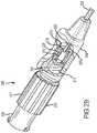
- FIG. 2Ais a perspective view of a needle that may be used in an RF neurotomy procedure.
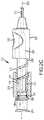
- FIG. 2Bis a cut away perspective view of a portion of the needle of FIG. 2A .
- FIG. 2Cis a cut away view of a portion of an alternate embodiment of a needle that may be used in an RF neurotomy procedure.
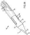
- FIG. 3Ais a detailed view of a tip of the needle of FIG. 2A with filaments disposed in a fully deployed position.
- FIG. 3Bis a detailed view of a tip of the needle of FIG. 2A with filaments disposed in a retracted position.
- FIG. 3Cis a detailed view of an alternate tip of the needle of FIG. 2A with filaments disposed in a deployed position.
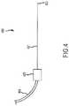
- FIG. 4is a schematic diagram of an RF probe assembly.
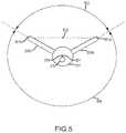
- FIG. 5is an end view of the needle of FIG. 2A .
- FIG. 6is a side view of the tip of the needle of FIG. 2A .
- FIG. 7is an end view of another alternate embodiment of the needle of FIG. 2A .
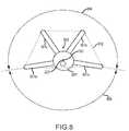
- FIG. 8is an end view of another alternate embodiment of the needle of FIG. 2A .
- FIG. 9is an end view of another alternate embodiment of the needle of FIG. 2A .
- FIG. 10is a side view of another alternate embodiment of the needle of FIG. 2A .
- FIG. 11Ais an illustration of an exemplary set of isotherms that may be created with the needle of FIG. 2A .
- FIG. 11Bis an illustration of an exemplary lesion that may be created with the needle of FIG. 2A .
- FIG. 11Cis an illustration of an exemplary lesion that may be created with a single-filament needle.
- FIG. 12is a perspective view of the needle of FIG. 2A positioned relative to a lumbar vertebra for performing RF neurotomy.
- FIG. 13is an illustration of a sacrum including target lesion volumes for performing Sacroiliac Joint (SIJ) RF neurotomy.
- SIJSacroiliac Joint
- FIG. 14is a perspective view of the needle of FIG. 2A positioned relative to a thoracic vertebra for performing RF neurotomy.
- FIG. 15is a perspective view of the needle of FIG. 2A positioned relative to the C2/3 cervical zygapophyseal joint (z joint) for performing cervical medial branch RF neurotomy on the third occipital nerve.
- the inventionis set forth in the context of apparatus and methods for performing RF ablation. More particularly, the systems and methods may be used to perform RF neurotomy to ablate portions of target nerves. Even more particularly, the systems and methods may be used to perform spinal RF neurotomy to ablate portions of target nerves along the spine of a patient to relieve pain.
- embodiments of methods and apparatuses described hereinrelate to lumbar RF neurotomy to denervate a facet joint between the L4 and L5 lumbar vertebrae. Denervation is achieved by application of RF energy to a portion of a medial branch nerve to ablate or cauterize a portion of the nerve, thus interrupting the ability of the nerve to transmit signals to the central nervous system.
- embodiments described hereinrelate to sacroiliac joint RF neurotomy.
- FIG. 1is an illustration of an RF neurotomy system 100 for performing RF neurotomy on a patient 101 .
- the patient 101may be positioned face down on a table 109 or surface to allow access along the spine of the patient 101 .
- the table 109may be made of radiolucent materials substantially transparent to x-rays, such as carbon fiber.
- the system 100may include an RF generator 102 capable of generating an RF energy signal sufficient to ablate target tissue (e.g. cause lesions in targeted volumes; cauterize targeted portions of target nerves).
- the RF generator 102may, for example, be capable of delivering RF energy of about 460,000-500,000 Hz.
- a needle 103 capable of conducting (e.g., transmitting or directing) RF energymay be interconnected to the RF generator 102 and may be used to deliver an RF energy signal to a specific site within the patient 101 .
- a return electrode pad 104may be attached to the patient 101 to complete a circuit from the RF generator 102 , through the needle 103 , through a portion of the patient 101 , and back to the RF generator 102 through the return electrode pad 104 .
- the needle 103may comprise at least one supply electrode and at least one return electrode to define the circuit.
- the RF generator 102may be operable to control the RF energy emanating from the needle 103 in a closed-loop fashion.
- the needle 103 and/or an RF probe disposed within the needle 103may contain a temperature measurement device, such as a thermocouple, to measure the temperature at the target tissue.
- Datamay also be available from the RF generator 102 , such as power level and/or impedance, which may also be used for closed-loop control of the needle 103 .
- the RF probe assembly 400includes an RF probe 401 that may be inserted into a patient (e.g., through needle 103 ) and may direct RF energy to the target tissue.
- the RF probe 401may include a thermocouple operable to measure temperature at a distal end 402 of the RF probe 401 .
- the RF probe assembly 400may include a connector 403 and a cable 404 for use in connecting the RF probe 401 to the RF generator 102 .
- the system 100may include an imaging system 105 capable of producing internal images of the patient 101 and the needle 103 to facilitate navigation of the needle 103 during a procedure.
- the system 100may further include a display for displaying the generated images to a physician performing the RF ablation procedure.
- the imaging system 105may be a fluoroscope capable of generating real-time two dimensional images of the needle 103 and internal structures of the patient 101 .
- the imaging systemmay include an X-ray source 106 , an X-ray detector 107 and a controller 108 .
- the X-ray source 106 and X-ray detector 107may be mounted on a movable structure (e.g., a C-arm), to facilitate capturing a variety of images of the patient 101 (e.g., at various angles or projection views).
- the imaging system 105may be any other appropriate imaging system, such as, for example, a computed tomography (CT) scanner.
- CTcomputed tomography
- FIG. 2Ais a detailed view of the needle 103 of the system 100 for performing RF neurotomy.
- the needle 103may include a tip 201 that tapers to a point 301 capable of piercing the skin of a patient.
- the needle 103may further include an elongate member 203 connected to the tip 201 at a distal end 202 of the needle 103 and connected to a hub 204 at a proximal end 205 of the needle 103 .
- the needle 103includes a central longitudinal axis 223 that is disposed along the center of the elongate member 203 .
- the needle 103may include a self-contained mechanical mechanism, in the form of deployable filaments 206 a , 206 b , operable to expand the volume of effective RF energy delivery as compared to known single-electrode RF probes.
- the filaments 206 a , 206 bmay be at least partially disposed within the elongate member 203 and may be operable to emerge through a side wall of the needle 103 proximate to the distal end 202 of the needle 103 .
- the needle 103may include a single filament or three or more filaments.
- the filaments 206 a , 206 ballow offsetting and/or contouring of the lesion geometry produced using the needle 103 to match a desired target volume.
- the filaments 206 a , 206 bmay be deployable and/or retractable by moving an actuator 216 relative to the hub 204 .
- the needle 103may further include a tube 207 that includes a lumen therethrough.
- the lumenmay be used to transport fluids to and/or from the target volume.
- the lumenmay also accept the RF probe 401 for delivery of RF energy to the target volume.
- the RF probe 401may be integrated into the needle 103 .
- the tube 207need not be present for RF energy delivery, although it may be included to facilitate fluid delivery.
- the filaments 206 a , 206 bmay include lumens therethrough for the transportation of fluid to and/or from the target volume.
- the filaments 206 a , 206 bmay function as thermocouples.
- the needle 103 with deployable filaments 206 a , 206 bovercomes this obstacle and expands the effective area of RF energy delivery by providing multiple locations (e.g., tip 201 and filaments 206 a , 206 b ) from which the RF energy emanates.
- the use of multiple filaments 206 a , 206 bprovides additional conduits for RF energy creating a multiple electrode RF field effect.
- the size, shape and location of a lesion created with the needle 103may be established by the quantity, location and orientation of the filaments, and may be beneficially modified to suit a specific anatomical application by changing various aspects of the filaments as discussed below.
- the lesionmay be preferentially offset in a desired direction from the central longitudinal axis 223 by rotationally orienting the needle 103 .
- the needle 103may be used to create a lesion offset from the central longitudinal axis 223 in a first direction. Then, the filaments 206 a , 206 b may be retracted, the needle 103 rotated, and the filaments 206 a , 206 b re-deployed to create a lesion offset from the central longitudinal axis 223 in a second direction.
- FIGS. 3A and 3Bare detailed views of the distal end 202 of the needle 103 that includes the tip 201 .
- the tip 201may include the sharpened point 301 for piercing the skin of a patient and facilitating advancement through tissue.
- the tip 201may further include a tapered portion 302 that transitions the tip 201 from the point 301 to a body portion 303 .
- the body portion 303is the portion of the tip 201 that is disposed proximal to the tapered portion 302 .
- the body portion 303may be cylindrical as illustrated, or it may be of any other appropriate shape.
- the body portion 303may have a cross-section that coincides with the cross section of the elongate member 203 .
- the tip 201may act as an RF energy delivery element.
- the tip 201may be made from a conductive material such as, for example, stainless steel.
- the tip 201may be coated.
- the tip 201 material and optional coatingmay be selected to improve radiopacity, improve and/or alter RF energy conduction, improve lubricity and/or reduce tissue adhesion.
- the tip 201may include filament port or slot 304 a (not visible in the views of FIGS. 3A and 3B ) and filament port or slot 304 b .
- the geometry of the filament slots 304 a , 304 bmay be selected to allow filaments 206 a , 206 b to be adequately retracted (e.g., such that they are disposed within a cross-sectional envelope of the body portion 303 of the tip 201 ) while the needle 103 is inserted into the body, so that the filaments 206 a , 206 b do not cause any unintended damage to the patient.
- Such positioning of the filament slots 304 a , 304 bavoids having filament exit features on the tapered portion 302 and thus avoids potential coring that could be caused by such positioning.
- the internal geometry of the filament slots 304 a , 304 bmay be designed such that the filaments 206 a , 206 b may be easily retracted and advanced.
- the internal geometry of the filament slots 304 a , 304 bmay include a transition region 305 that meets the outer surface of the body portion 303 at an angle of about 30 degrees.
- the transition region 305may, for example, be curved or planar.
- the filaments 206 a , 206 bare in the form of a member without a pre-set bias (e.g., substantially straight)
- advancement of the filaments 206 a , 206 b relative to the filament slots 304 a , 304 bwill cause the filaments 206 a , 206 b to be deflected outwardly as the filaments 206 a , 206 b move distally along the transition region 305 .
- the transition region 305relative to where the filaments 206 a , 206 b are confined (e.g., in the needle 103 of FIG.
- the filaments 206 a , 206 bare confined to only longitudinal movement where they enter into the elongate member 203 ) and on the mechanical properties of the filaments 206 a , 206 b , various deployment angles of the filaments 206 a , 206 b relative to the central longitudinal axis 223 may be achieved.
- the portions of the filaments 206 a , 206 b that extend outwardly away from the filament slots 304 a , 304 bmay be unrestrained and thus may take any appropriate form.
- the portions of the filaments that extend outwardly away from the filament slots (and therefore from the tip)may be substantially straight, such as shown in FIGS.
- the portions of the filaments that extend outwardly away from the filament slotsmay take any appropriate shape, such as, for example, curved as shown in FIG. 10 .
- the radial orientation of the filament slots 304 a , 304 bmay be selected such that a center point between the filament slots 304 a , 304 b does not coincide with the central longitudinal axis 223 .
- the filament slots 304 a , 304 bmay be positioned such that they are about 120 degrees apart about the circumference of the tip 201 .
- Other filament slot configurationsmay be configured to achieve the filament placements discussed below. These configurations may be achieved by varying the quantity of filament slots, the placement of filament slots about the circumference of the tip 201 , and/or the placement of filament slots along the center longitudinal axis 223 to achieve the filament placements discussed below.
- the needle 103may comprise a tube 207 that includes a lumen 222 therethrough.
- the lumen 222may be employed to accept the RF probe 40 for delivery of RF energy and/or for the transport of fluids.
- the tip 201may further include a fluid port 210 that may be in fluid communication via a channel through the tip 201 with the lumen 222 .
- the fluid port 210may be centrally located or it may be located offset from the center longitudinal axis 223 as shown in FIGS. 2A and 3A .
- the fluid port 210may be used to transfer fluid between the region of the tip 201 and the proximal end 205 of the needle 103 .
- an anesthetic and/or an image enhancing dyemay be introduced into the region of tissue around the tip 201 through the fluid port 210 .
- the fluid port 210may be located along the body portion 303 of the tip 201 .
- the channel through the tip 201may be sized to accommodate a tip of the RF probe 401 that may be inserted into the needle 103 .
- the channelmay be sized such that RF energy from the inserted RF probe 401 is satisfactorily passed from the RF probe 401 to the tip 201 and filaments 206 a , 206 b.
- the elongate member 203may be in the form of a hollow tube (e.g., sheath, cannula) interconnecting the tip 201 with the hub 204 .
- the elongate member 203may be configured with adequate strength to allow the needle 103 to pierce the patient's skin and advance to a target area through various tissue types, including, for example, fat and muscle tissue.
- the elongate member 203may also be capable of resisting kinking as it is advanced.
- the elongate member 203may be a rod with a plurality of lumens along its length to accommodate filaments 206 a , 206 b , the RF probe 401 , and/or a fluid passage.
- the elongate member 203houses portions of the filaments 206 a , 206 b and the tube 207 , and allows for relative movement of the filaments 206 a , 206 b .
- the elongate member 203may be of any appropriate size and internal configuration to allow insertion into the patient 101 and to house componentry therein.
- the elongate member 203may, for example, be a 16 gauge round tube or smaller.
- the elongate member 203may be 18 or 20 gauge.
- the elongate membermay have a maximum cross dimension of at most about 1.7 mm. In another example, the elongate member may have a maximum cross dimension of at most about 1 mm.
- the elongate member 203may have a length selected for performing a specific spinal RF neurotomy procedure on a particular patient.
- the elongate member 203may be constructed from an insulative material to reduce the amount of RF energy emitted along the length of the elongate member 203 when the RF probe 401 is disposed therein.
- the elongate member 203may be constructed from polymeric, ceramic or other insulative material.
- the elongate member 203may include a coating that may improve radiopacity to aid in visualization of the position of the needle 103 using fluoroscopy.
- the elongate member 203may include a coating to improve its insulative properties.
- the elongate member 203may include a lubricious coating to improve its ability to be inserted and positioned within the patient and to reduce tissue adhesion.
- the elongate member 203may include markers 224 along its length to assist in determining the depth to which the needle 103 has entered into the anatomy. Such markers 224 may be radiopaque so that they may be viewed under fluoroscopy.
- a collar(not shown) may be disposed about the elongate member 203 to assist in placement of the tip 201 of the needle 103 . For example, the tip 201 may be positioned in a first position, the collar may then be placed against the patient's 101 skin, and then the needle 103 may be withdrawn a certain distance. Such a distance will be indicated by the distance between the collar and the patient's 101 skin.
- the elongate member 203may be fixedly interconnected to the tip 201 and hub 204 in any appropriate manner.
- the tip 201may be press fit into the elongate member 203 and the elongate member 203 may be press fit into the hub 204 .
- Other possible methods of attachmentinclude adhesive bonding and welding.
- the elongate member 203 and the tip 201may be a single unitary structure.
- the elongate member 203may be steerable and incorporate controlling mechanisms allowing the elongate member 203 to be deflected or steered after insertion into the anatomy.
- the tube 207 containing the lumen 222may be constructed from any appropriate material.
- the tube 207may be constructed from a conductive material, such as stainless steel, such that when the RF probe 401 is inserted within the tube 207 , the RF energy emitted by the RF probe 401 may be conducted through the tube 207 and into and through the tip 201 and filaments 206 A, 206 b .
- the tube 207may be interconnected to the tip 201 such that the lumen 222 is in sealed, fluid communication with the channel through the tip 201 . This may be accomplished by a press fit, weld, or any other appropriate method.
- the lumen 222may be in fluid communication with the tip 201 at the distal end 202 .
- a proximal end of the lumen 222may be disposed at the proximal end 205 of the needle 103 .
- the lumen 222may run from the distal end 202 to the proximal end 205 with the only access being at the distal and proximal ends.
- the lumen 222may be the only lumen of the needle 103 disposed along the elongate member 103 .
- the RF probe 401 inserted into the lumen 222may be positioned such that an end of the RF probe 401 is proximate the tip 201 .
- the RF probe 401may be positioned such that the distal end 402 of the RF probe 401 is in the lumen 222 near the tip 201 or in the channel through the tip 201 .
- RF energy transmitted through the RF probe 401may be conducted by the tip 201 and filaments 206 a , 206 b .
- the size of the lumen 222may be selected to accommodate a particular size of RF probe 401 .
- at least a 21 gauge or larger lumen 222may be employed.
- the lumen 222may have a maximum cross-dimension of less than about 0.85 mm.
- the proximal end of the tube 207may be operable to receive the RF probe 401 .
- the proximal end of the tube 207 and the actuator 216may be configured to accept a connector, such as a Luer fitting, such that a fluid source may be connected to the tube 207 .
- the needle 103includes two filaments 206 a , 206 b disposed within and along elongate member 203 . Distal ends of the filaments 206 a , 206 b are disposed proximate to the tip 201 and proximal ends of the filaments 206 a , 206 b are fixed to a filament hub 221 discussed below.
- the filaments 206 a , 206 bare movable along the central longitudinal axis 223 between a fully deployed position as illustrated in FIGS. 2A and 3A and a retracted position illustrated in FIG. 3B .
- Moving the filaments 206 a , 206 b distally from the retracted positionmoves the filaments 206 a , 206 b toward the fully deployed position, while moving the filaments 206 a , 206 b proximally from the deployed position moves the filaments 206 a , 206 b toward the retracted position.
- the filaments 206 a , 206 bmay be deployed in intermediate positions between the fully deployed positions and the retracted positions.
- the distal ends of the filaments 206 a , 206 bare disposed away from the tip 201 .
- the distal ends of the filaments 206 a , 206 bare disposed entirely within an outer perimeter (e.g., circumference where the non-tapered portion 303 of the tip 201 is round) of the tip 201 .
- the filaments 206 a , 206 bact as broadcast antennae for the RF probe 401 (e.g., RF energy passes from the RF probe 401 to tip 201 and filaments 206 a , 206 b , and into a target volume within the patient 101 ).
- the RF probe 401 inserted into the lumen 222 , the tip 201 , and the filaments 206 a , 206 bmay form a monopolar electrode for application of RF energy to the target volume.
- the filaments 206 a , 206 ballow the RF energy from the RF probe 401 to be dispersed over a larger volume than would be possible with the tip 201 alone.
- the filaments 206 a , 206 bmay be constructed from a material operable to conduct RF energy, e.g., a metal such as stainless steel, Nitinol or shape memory alloy.
- the filaments 206 a , 206 bmay be coated to enhance their ability to conduct RF energy.
- the filaments 206 a , 206 bmay include a lubricious coating to aid in insertion and/or reduce tissue adhesion.
- the distal ends of the filaments 206 a , 206 bmay be shaped (e.g., pointed) to improve their ability to move through tissue.
- FIG. 5is an end view of the tip 201 and deployed filaments 206 a , 206 b of the embodiment illustrated in FIGS. 2A and 3A .
- the filaments 206 a , 206 bare positioned at a filament angle 503 of about 120 degrees apart from each other about the central longitudinal axis 223 . This coincides with the positions of the filament slots 304 a , 304 b discussed above since the filaments 206 a , 206 b emerge from the filament slots 304 a , 304 b .
- a filament-free angle 504 of about 240 degreesis defined as the largest angle about the circumference of the tip 201 that is free of filaments 206 a , 206 b .
- the filament angle 503may be less than 180 degrees and the filament-free angle 504 may be correspondingly greater than 180 degrees (e.g., greater than 200 degrees or greater than 240 degrees).
- the central longitudinal axis 223is perpendicular to the plane of the illustration.
- a midpoint 502is defined between distal ends 501 a , 501 b of the filaments 206 a , 206 b , respectively.
- the midpoint 502is offset from the central longitudinal axis 223 .
- the midpoint 502may be offset from the central longitudinal axis 223 by about 2 mm. Accordingly, when RF energy is transmitted from the tip 201 and filaments 206 a , 206 b , it will be transmitted asymmetrically with respect to the central longitudinal axis 223 as energy will be emitted from the tip 201 and the filaments 206 a , 206 b .
- the energywill be biased in an upward direction in the direction from the point 301 toward the midpoint 502 .
- a lesionwill be created that is correspondingly offset from the central longitudinal axis 223 in the direction from the point 301 toward the midpoint 502 .
- FIG. 6is a side view of the tip 201 and filaments 206 a , 206 b oriented such that deployed filament 206 b is disposed entirely within the plane of the figure.
- the filaments 206 a , 206 bextend from the tip 201 at a common distance, or location, along the central longitudinal axis 223 .
- the filament 206 bis deflected radially outwardly from the central longitudinal axis 223 .
- the filament 206 bemerges from the tip 201 at an angle 601 of about 30 degrees as dictated by the positioning of the transition region 305 relative to where the filament 206 b is confined and on the mechanical properties of the filament 206 b (as previously discussed).
- the distal tips 501 a , 501 bare positioned distally beyond the point 301 by a distance 602 and are disposed at a distance 603 from the central longitudinal axis 223 .
- the distance 602may be about 3.5 mm and the distance 603 may be about 3 mm.
- Such an arrangementmay distally offset a lesion created by the needle 103 as compared to a lesion created with a tip without filaments or a lesion created with the needle 103 with the filaments 206 a , 206 b in the retracted position.
- the filament 206 a , 206 b arrangement illustrated in FIGS. 2A, 3A, 3B, 5 and 6may be operable to produce lesions that are radially offset from the central longitudinal axis 223 and distally offset from the point 301 as compared to a lesion created by the tip 201 without the filaments or a lesion created with the needle 103 with the filaments 206 a , 206 b in the retracted position.
- Variations of filament positions and configurations from those illustrated in FIGS. 2A, 3A, 3B, 5 and 6will now be addressed. Variations in the relative shapes, positions and sizes of lesions created with the needle 103 may be achieved by repositioning the filaments. For example, as noted above, the lesion produced by the needle 103 will be in different positions depending on whether the filaments are in the deployed or refracted positions. Accordingly, intermediately shaped, positioned and/or sized lesions may be achieved by positioning the filaments in intermediate positions between the fully deployed or refracted positions. Thus, for any given configuration of deployable filaments discussed herein, the positions and/or sizes of lesions created by those configurations may be varied by varying the positioning of the filaments to intermediate positions between the fully deployed and retracted positions. As noted above, the needle 103 with deployed filaments is operable to produce larger lesion volumes than the needle 103 with retracted filaments. For example, the needle 103 with fully deployed filaments may be operable to produce lesion volumes of about 500 mm 3 .
- the shape, position and/or size of lesions created by needles with deployable filamentsmay be achieved by different configurations of filaments. Variations may include variations in materials, the number of filaments, the radial positioning of the filaments, the axial positioning of the filaments, the length of the filaments, the angle at which the filaments exit the tip, and the shape of the filaments. By varying these parameters the needle may be configured to produce lesions of various sizes and shapes that are positioned at various locations relative to the tip. Such variations may be specifically tailored to be used in specific procedures, such as RF neurotomy procedures of particular nerves adjacent to particular vertebrae.
- Variations of the materials used for the tip and/or the filamentsmay be selected to achieve particular lesion sizes, positions and/or shapes.
- the tipmay be made form a material that does not conduct RF energy.
- RF energy from the RF probe 401may be conducted by substantially only the deployed filaments.
- Such an arrangementmay provide for a lesion with a larger offset from the central longitudinal axis 223 than would be produced where the tip conducts RF energy and acts as an electrode along with the filaments.
- Another material-related variation that may affect lesion shape, size and/or positionis the addition and placement of insulation over the tip and/or filaments. For example, by placing a layer of insulation over the proximal half of the portions of the filaments that extend from the tip when in the deployed position, the shape of the lesion may be altered since RF energy may primarily emanate from the distal, non-insulated portion of the filaments. Similarly, insulation may be added to the tip to alter the RF energy delivered from the tip.
- the materials used in making the filaments and tipmay be selected based on RF conductivity. For example, by using a material for the tip that is less conductive of RF energy, the proportion of RF energy emanating from the tip as compared to that emanating from the filaments may be altered resulting in a corresponding change in lesion size, position and/or shape.
- the RF needles and RF probes discussed hereinmay be constructed from materials that are Magnetic Resonance Imaging (MRI) compatible. As such, MRI equipment may be used to verify the positioning of such RF needles and/or monitor the progress of an ablation procedure (e.g., RF neurotomy) using such RF needles.
- MRIMagnetic Resonance Imaging
- Variations of the number of filaments used for needlemay be selected to achieve particular lesion sizes, positions and/or shapes.
- a third filament 701may extend from tip 201 ′ in a position between filaments 206 a , 206 b .
- the tips 501 a , 501 b of the filaments 206 a , 206 b and a tip 702 of filament 701may form a polygon 703 that has a centroid 704 .
- the centroid 704is offset from the central longitudinal axis 223 .
- Such an arrangementmay produce a lesion that is offset from the central longitudinal axis 223 to a different degree than, and shaped differently than, a lesion created by the needle of FIG. 5 .
- a lesion created by such a configurationwill be correspondingly offset from the central longitudinal axis 223 .
- the filaments 206 a , 206 b , 702are positioned within the same filament angle 503 of about 120 degrees as in the embodiment of FIG. 5 .
- the embodiment of FIG. 7has a filament-free angle 504 of about 240 degrees, also the same as in the embodiment of FIG. 5 .
- the filament-free anglemay be correspondingly greater than 180 degrees (e.g., greater than 200 degrees or greater than 240 degrees).
- Variations in the radial positioning of filaments of a needlemay be selected to achieve particular lesion sizes, positions and/or shapes.
- four filaments 801 a - 801 dare positioned about a tip 201 ′′.
- the tips of the filaments 801 a - 801 dmay form a polygon 802 that has a centroid 803 .
- Such an arrangementmay produce a lesion whose center is offset from the central longitudinal axis 223 in the direction of the centroid 803 .
- the filaments 801 a - 801 dare positioned within a filament angle 804 of about 200 degrees.
- a configuration capable of producing a lesion offset from the central longitudinal axis 223may have a filament-free angle that is less than 180 degrees.
- a midpoint 502 between the filamentswas discussed.
- a centroid of a polygon formed by the distal ends of the filamentswas discussed. Both the midpoints and the centroids may be considered to be “average” points of the filaments for their particular configurations.
- the midpoint between filaments in two-filament embodiments and the centroid of the polygon in embodiments with more than two filamentsmay be offset from the central longitudinal axis of the elongate member.
- the midpoint or centroidmay be offset from the central longitudinal axis by 1 mm or more.
- the polygonmay lie in a plane perpendicular to the central longitudinal axis.
- the distal ends of the filaments when fully deployedmay be disposed in a common plane.
- the common planemay be disposed perpendicular to the central longitudinal axis.
- Such a common plane for the distal ends of deployed filamentsmay be disposed distally from the distal end of the tip.
- the filaments of the needlemay be deployed on a common side of a central plane of the needle (where the central longitudinal axis is disposed entirely within the central plane).
- the distal ends of the fully deployed filamentsmay all be disposed on a common side of the central plane.
- Such a configurationmay enable the needle to be used to create a lesion that is offset from the tip of the needle to the same side of the central plane as the deployed filament ends.
- the filaments when fully deployedmay point in an at least partially distal direction.
- a vector extending axially from the distal end of a filament and coinciding with a central axis of the filament at the end of the filamenthas at least some distal component.
- the fully deployed filaments embodiments shown in FIGS. 2A, 3A and 10all point in an at least partially distal direction.
- the filamentsmay be uniformly distributed about the circumference of the tip.
- FIG. 9An embodiment is illustrated in FIG. 9 .
- the needle of FIG. 9includes 3 equally distributed filaments 901 a , 901 b , 901 c . Consequently, the angles 902 a , 902 b , 902 c between the filaments 901 a , 901 b , 901 c may each equal 120 degrees.
- Such a needlemay be operable to produce a lesion that is generally centered along the central longitudinal axis 223 . However, the position of the produced lesion axially along the central longitudinal axis 223 may be determined by the configuration of the filaments. For example, relatively longer filaments may be operable to produce lesions that are positioned distal to lesions produced by configurations with relatively shorter filaments.
- Variations in the axial positioning of where deployed filaments emerge from the tip of a needlemay be selected to achieve particular lesion sizes, positions and/or shapes. For example, returning to FIG. 7 , if the third filament 701 of the embodiment of FIG. 7 were axially positioned such that it is distal to filaments 206 a , 206 b , the resultant lesion may be produced may be longer along the central longitudinal axis 223 than that of an embodiment where the filaments 206 a , 206 b , 701 are positioned at the same point along the central longitudinal axis 223 . In another variation, as deployed, two or more filaments may be disposed at the same radial position and at different axial positions. Such embodiments may include multiple rows of filaments.
- the lengths of filaments beyond the tip (when the filaments are in the deployed position) in a needlemay be varied to achieve particular lesion sizes, positions and/or shapes. For example, increasing the length of the deployed portions of the filaments 206 a and 206 b of the embodiment illustrated in FIGS. 5 and 6 may result in a needle capable of producing lesions that are more distally positioned than those created by the embodiment as shown in FIGS. 5 and 6 .
- the effects of lengthening or shortening the deployed length of the filamentsare similar to those discussed above with respect to partially deploying filaments.
- Embodiments of a needlemay include deployed filaments of different lengths. Where all of the filaments of a particular needle are moved by a common actuator, such variations may be achieved by varying the overall length of the filaments. In such an embodiment, the end points of the shorter filaments may be retracted further into the tip or elongate member than longer filaments. The effects of lengthening or shortening the deployed length of the filaments are similar to those discussed above with respect to variations in the axial positioning of where deployed filaments emerge from the tip of the needle.
- the angle (such as angle 601 of FIG. 6 ) at which a filament exits a tipmay be varied to achieve particular lesion sizes, positions and/or shapes.
- an embodiment similar to the embodiment of FIGS. 5 and 6but where the deployed filaments are at a 60 degree angle instead of the 30 degree angle shown in FIG. 6 , may be operable to produce a lesion that has a larger maximum cross-sectional dimension in a plane perpendicular to the central longitudinal axis 223 than the embodiment of FIGS. 5 and 6 . This may be due to the filaments emanating RF energy at a distance further away from the central longitudinal axis than the embodiment of FIGS. 5 and 6 .
- a particular embodiment of the needlemay include deployed filaments at different angles relative to the central longitudinal axis.
- FIG. 10illustrates the tip 201 and filaments 1001 a , 1001 b , where the portions of the filaments 1001 a , 1001 b that extend beyond the tip 201 are curved.
- Such curvaturesmay be achieved by, for example, filaments that comprise a shape memory alloy (e.g., Nitinol) or spring material.
- the deployed shape of the filaments 1001 a , 1001 bmay be predetermined, or the filaments 1001 a , 1001 b may be made from a material that may be shaped by a user prior to insertion.
- the curved filaments 1001 a , 1001 b of FIG. 10are positioned within planes that include the central longitudinal axis 223 .
- the filaments 1001 a , 1001 bmay be curved in other directions, such as in a corkscrew arrangement. This may be beneficial to assist the filaments in remaining anchored to the tissue during delivery of RF energy.
- the curved filaments 1001 a , 1001 b of FIG. 10may be operable to produce a flatter (in a plane perpendicular to the central longitudinal axis 223 ) lesion than the straight filaments 206 a , 206 b of FIG. 6 .
- FIG. 3Cis a detailed view of the distal end 310 of a needle 309 that is an alternate embodiment of the needle 103 .
- the distal end 310includes a tip 311 that may include a sharpened point 312 for piercing the skin of a patient and facilitating advancement through tissue.
- the tip 311may further include a tapered portion 313 that transitions the tip 311 from the point 312 to a first body portion 314 .
- the first body portion 314may be connected to a second body portion 315 at an angle 316 . In an exemplary embodiment, the angle 316 may be about 15°.
- the second body portion 315may be aligned with an elongate member 317 .
- the elongate member 317may be similarly configured as the elongate member 203 of FIGS. 3A and 3B .
- the angle 316 between the first body portion 314 and the second body portion 315may aid the physician in navigating the needle 309 to a desired position. For example, by rotating the needle 309 such that the first body portion 314 is pointing in a desired direction, subsequent advancement of the needle 309 may result in the needle 309 following a non-straight path biased toward the desired direction.
- the first and second body portions 314 , 315may be cylindrical as illustrated, or they may be of any other appropriate shape.
- the first and second body portions 314 , 315may have cross-sections that coincide with the cross section of the elongate member 317 .
- the tip 311may act as an RF energy delivery element.
- the tip 311may be made from a conductive material such as, for example, stainless steel.
- the tip 311may be coated.
- the tip 311 material and optional coatingmay be selected to improve radiopacity, improve and/or alter RF energy conduction, improve lubricity and/or reduce tissue adhesion.
- the tip 311may include filament slot 318 a and filament slot 318 b .
- the geometry of the filament slots 318 a , 318 bmay be selected to allow filaments 319 a , 319 b to be adequately retracted (e.g., such that they are disposed within a cross-sectional envelope of the second body portion 315 ) while the needle 309 is inserted into the body, so that the filaments 319 a , 319 b do not cause any unintended damage to the patient.
- Such positioning of the filament slots 318 a , 318 bavoids having filament exit features on the tapered portion 313 and on the first body portion 314 and thus avoids potential coring that could be caused by such positioning.
- the internal geometry of the filament slots 318 a , 318 bmay be designed such that the filaments 319 a , 319 b may be retracted and advanced.
- the internal geometry of the filament slots 318 a , 318 bmay be configured such that advancement of the filaments 319 a , 319 b relative to the filament slots 318 a , 318 b , will cause the filaments 319 a , 319 b to be deflected outwardly as the filaments 319 a , 319 b move distally relative to the second body portion 315 .
- various deployment angles of the filaments 319 a , 319 b relative to a central longitudinal axis of the second body portion 315may be achieved.
- the configuration and orientation of the filament slots 318 a , 318 bmay be selected such that deployed filaments 319 a , 319 b may achieve the positioning illustrated in FIG. 3C .
- the filaments 319 a , 319 bare generally positioned in a plane that is perpendicular to a plane that includes the angle 316 between the first and second body portions 314 , 315 .
- the filaments 319 a , 319 bmay be positioned such that they extend at an angle relative to the plane that includes the angle 316 .
- Other filament slot 318 a , 318 b configurationsmay be configured to achieve other desired filament 319 a , 319 b placements.
- These configurationsmay be achieved by varying the quantity of filament slots and filaments, the placement of filament slots about the circumference of the tip 311 , the angle at which the filaments extend away from the first and second body portions 314 , 315 , and/or the placement of filament slots along the first and second body portions 314 , 315 .
- the needle 309may comprise a tube that includes a lumen therethrough.
- the lumenmay be employed to accept an RF probe for delivery of RF energy and/or for the transport of fluids.
- the tip 311may further include a fluid port 320 that may be in fluid communication via a channel through the tip 311 with the lumen.
- the fluid port 320may be used to transfer fluid between the region of the tip 311 and a proximal end of the needle 309 .
- the distal ends of the filaments 319 a , 319 bare disposed away from the tip 311 .
- the distal ends of the filaments 319 a , 319 bare disposed entirely within an outer perimeter (e.g., circumference where the second body portion 315 of the tip 311 is round) of the tip 311 .
- the filaments 319 a , 319 bact as broadcast antennae for an RF probe inserted into the needle 309 .
- the RF probe inserted into the lumen, the tip 311 , and the filaments 319 a , 319 bmay form a monopolar electrode for application of RF energy to the target volume.
- the filaments 319 a , 319 bmay allow the RF energy from the RF probe to be dispersed over a larger volume than would be possible with the tip 311 alone.
- the filaments 319 a , 319 bmay be constructed in a manner similar to as described with respect to the filaments 206 a , 206 b.
- any or all of the above variablesmay be incorporated into a particular embodiment of a needle to yield a needle capable of producing a lesion with a particular size, position and shape relative to the tip of the needle.
- Such custom sizes, positions and shapesmay be designed for specific procedures.
- a particular lesion size, position and shapemay be selected to enable a physician to navigate the needle to a particular landmark (e.g., proximate or touching a bone visible using fluoroscopy) and then orient the needle such that deployed filaments will be operable to produce a lesion at a particular location relative to the landmark.
- the lesion shapes achievable through selection of the above variablesmay include, for example, generally spherical, oblong, conical, and pyramidal shapes.
- the orientation relative to, and the amount of offset from, the tip of such shapesmay be selectable.
- the tips of the deployed filamentsmay be positioned distally relative to the point of the tip to provide for a facile positioning of the lesion relative to the tip. Such capability may allow for the needle to be inserted directly toward a target volume.
- the tips of the deployed filamentsmay be positioned at the same axial position along the central longitudinal axis as the point of the tip or the tips of the deployed filaments may be positioned proximally relative to the point of the tip.
- some filament endpointsmay be located distal to the point of the tip while others are disposed proximal to the point of the tip.
- the filaments 206 a , 206 bhave been illustrated as running the entire length of the elongate member 203 from the filament hub 221 to the tip 201 .
- a single membermay run along at least part of the elongate member 203 and the filaments may be interconnected to the single member at some point proximal to the tip 201 .
- the filaments 206 a , 206 bhave been illustrated as being straight within the elongate member 203 .
- the filaments within the elongate member 203may be braided, wrapped or twisted together. Such embodiments may have increased column strength, providing resistance to buckling and/or bending within the elongate member 203 .
- the filaments discussed hereinmay be encased within lumens sized to help prevent buckling or bending of the filaments within the elongate member 203 .
- Such lumensmay be part of the elongate member or they may be separate members (e.g., tubes within the elongate member).
- Such lumensmay be formed by an inner member (not shown) within the elongate member where the inner member includes channels along its periphery in which the filaments may lie with the elongate member forming a portion of the lumens.
- Lumens used for filamentsmay also serve as lumens for the transfer of liquid to and/or from the region surrounding the tip.
- the filamentsmay be hollow and may be used for transfer of liquid to and/or from the region surrounding the tip.
- the illustrated embodimentsshow all of the filaments of a given embodiment as commonly deployed or refracted.
- one or more filamentsmay be separately deployed and/or refracted such that the physician could selectively engage a desired number of elements.
- a plurality of filamentsmay exit from the tip at a common location and form a fan-like arrangement as they are deployed.
- filamentse.g., curved shape memory filaments
- embodimentsmay be deployed by pulling the tip back relative to the filaments.
- Such embodimentsmay be beneficial where the needle is initially advanced such that it is in contact with bone to ensure proper positioning. Then the tip may be withdrawn, leaving the filaments (e.g., curved shape memory filaments) in a precise, known position.
- the hub 204may be fixedly attached to the elongate member 203 .
- the hub 204may be the primary portion of the needle 103 gripped by the physician during insertion and manipulation of the needle 103 .
- the hub 204may have an asymmetric feature, such as indicator 225 , that is oriented in a known fashion relative to the asymmetry of the tip 201 .
- the indicator 225may be used to communicate to the physician the orientation of the tip 201 within the patient 101 .
- the hub 204may include a cavity 213 sized to house a protrusion 218 of the actuator 216 .
- the hub 204may include a hole through which a projection 215 may project into the interior of the cavity 213 to control the motion of the actuator 216 relative to the hub 204 and to secure the actuator 216 to the hub 204 .
- the hub 204may be made from any appropriate material, e.g., a thermoset plastic.
- the actuator 216may be used to control the motion to deploy and/or retract the filaments 206 a , 206 b .
- the actuator 216is operable to move along the central longitudinal axis 223 relative to the hub 204 , elongate member 203 and tip 201 .
- the actuator 216includes the protrusion 218 extending into the cavity 213 of the hub 204 .
- the outer surface of the protrusion 218includes a helical track 219 sized to accommodate the projection 215 .
- the helical track 219 and projection 215combine to cause the actuator 216 to move axially along the central longitudinal axis 223 .
- the actuator 216has an interface portion 217 that may be gripped by a user when twisting the actuator 216 .
- the interface portion 217may be knurled or otherwise textured to enhance the physician's ability to twist the actuator 216 .
- the protrusion 218may include an inner cavity 226 sized to accept the filament hub 221 and to allow the filament hub 221 to rotate freely relative to the actuator 216 .
- the linear motion of the actuator 216may be transmitted to the filament hub 221 while the rotational motion of the actuator 216 may not be transmitted to the filament hub 221 .
- the actuator 216may include a Luer fitting 220 or any other appropriate fitting type on a proximal end thereof.
- the Luer fitting 220may be in fluid communication with the lumen 222 and provide a connection such that fluid may be delivered into the lumen 222 and to the fluid port 210 of the tip 201 .
- the Luer fitting 220may also be configured to allow for the insertion of the RF probe 401 into the lumen 222 .
- the actuator 216may be made from any appropriate material.
- the filaments 206 a , 206 bmay be fixedly interconnected to the filament hub 221 .
- the axial movement of the filament hub 221 due to the actuator 216may be communicated to the filaments 206 a , 206 b to deploy and retract the filaments 206 a , 206 b when the actuator 216 is rotated.
- the filament hub 221may be made from any appropriate material.
- the physicianmay be able to deploy or retract the filaments 206 a , 206 b by twisting the actuator 216 .
- a counterclockwise (as seen from the viewpoint of FIG. 5 ) rotation of the actuator 216 relative to the hub 204will result in the deployment (extension) of the filaments 206 a , 206 b .
- a clockwise rotation of the actuator 216 relative to the hub 204will result in the retraction of the filaments 206 a , 206 b .
- the filaments 206 a , 206 bmay be partially deployed or refracted.
- the actuator 216 and/or the hub 204may include markings to indicate the position of the filaments 206 a , 206 b (e.g., the depth of deployment).
- the actuator 206 and/or hub 204may include detents to provide a tactile feedback of the position of the filaments 206 a , 206 b.
- a spring loaded mechanismmay be used. Such a configuration may use a spring that acts upon the filaments 206 a , 206 b to bias the filaments 206 a , 206 b toward a predetermined position (e.g., either deployed or retracted). Such a mechanism may be analogous to a spring loaded mechanism used in retractable ballpoint pens.
- a roll clamp mechanismmay be incorporated. A roller wheel could be incorporated into the hub 204 such that as the wheel is rotated with the user's thumb, the filaments 206 a , 206 b would advance or retract.
- the hub 204 and actuator 216may interact via complimentary threaded features. As the actuator 216 is threaded into the hub 204 , the filaments 206 a , 206 b would advance. As the actuator 216 is threaded out of the hub 204 , the filaments 206 a , 206 b would retract. In another example, a Touhy-Borst type mechanism could be incorporated to control the deployment and retraction of the filaments 206 a , 206 b . Any other appropriate mechanism for controlling linear motion of the filaments 206 a , 206 b may be incorporated into the needle 103 .
- FIG. 2Cis a cut away view of a portion of an alternate embodiment of a hub 231 and actuator 232 that may be part of RF needle 103 used in an RF neurotomy procedure.
- the hub 231may be fixedly attached to the elongate member 203 .
- the hub 231may be the primary portion of the needle 103 gripped by the physician during insertion and manipulation of the needle 103 .
- the hub 231may have an asymmetric feature, such as indicator 233 , that is oriented in a known fashion relative to the asymmetry of the tip 201 .
- the indicator 233may be used to communicate to the physician the orientation of the tip 201 within the patient 101 .
- the hub 231may include a cavity 234 sized to house a protrusion 235 of a slide member 236 .
- the protrusion 235may include a keyway or key slot 237 that may run along a longitudinal direction of the protrusion 235 .
- the internal surface of the hub 231 through which the protrusion 235 movesmay include a mating key (not shown) configured to fit and slide within the key slot 237 .
- the key slot 237 and mating key of the hub 231may limit the slide member 236 to a linear motion along the central longitudinal axis 223 .
- Filaments 206 a , 206 bmay be fixedly connected to the protrusion 235 of the slide member 236 for movement therewith.
- distal movemente.g., movement to the right as shown in FIG. 2C
- extension of the filaments 206 a , 206 b relative to the hub 231 , elongate member 203 and tip 201(not shown in FIG. 2C ).
- distal movement of the protrusion 235may be used to move the filaments 206 a , 206 b from a retracted position to a deployed position.
- proximal movemente.g., movement to the left as shown in FIG.
- the hub 231may be made from any appropriate material, e.g., a thermoset plastic.
- the hub 231may be at least partially transparent such that the position of the protrusion 235 and/or other components within the hub 231 may be observable by a user.
- the hub 231may further include demarcations (e.g., molded or printed marks) such that the amount of extension of the filaments 206 a , 206 b may be determined from the position of the protrusion 235 and/or other components relative to the demarcations.
- An actuator 232may be used to control the motion to deploy and/or retract the filaments 206 a , 206 b fixedly connected to the protrusion 235 .
- the actuator 232may be generally tubular such that it may fit around a hub projection 238 projecting from the proximal end of the hub 231 . At least a portion of the cavity 234 may be disposed within the hub projection 238 .
- the actuator 232may also include an annular feature 239 configured to fit within an annular slot 240 in the slide member 236 .
- the annular feature 239may be sized relative to the annular slot 240 such that the actuator 232 may rotate relative to the slide member 236 about the central longitudinal axis 223 (or an axis parallel thereto) while the position of the actuator 232 relative to the slide member 236 along the central longitudinal axis 223 remains fixed.
- the actuator 232 and the slide member 236may be configured to move in tandem relation along the central longitudinal axis 223 .
- the annular feature 239 and annular slot 240may be configured such that, during assembly, the actuator 232 may be pressed onto the slide member 236 and the annular feature 239 may snap into the annular slot 240 .
- the inner surface of the actuator 232may include a helical track 241 sized to accommodate a corresponding mating helical thread 242 on the hub projection 238 .
- the helical track 241 and helical thread 242combine to cause the actuator 232 and the slide member 236 to move axially along the central longitudinal axis 223 .
- a linear motion of the slide member 236 relative to the hub 231may be created while the rotational motion of the actuator 232 may not be transmitted to the slide member 236 and the hub 231 .
- An outer surface of the actuator 232may be textured or include features to assist the user in gripping and twisting the actuator 232 .
- the helical track 241may be disposed on the hub projection 238 and the helical thread 242 may be disposed on the inner surface of the actuator 232 .
- the slide member 236may include a Luer fitting 243 or any other appropriate fitting type on a proximal end thereof.
- the Luer fitting 243may be in fluid communication with a lumen passing through the slide member 236 and may provide a connection such that fluid may be delivered through the Luer fitting 243 and into the lumen of the slide member 236 .
- the lumen of the slide member 236may be in fluid communication with the cavity 234 of the hub 231 , which may in turn be in fluid communication with a lumen disposed within the elongate member 223 .
- the lumen disposed within the elongate member 223may be in fluid communication with the tip 201 .
- fluidmay flow into the Luer fitting 243 , into and through the lumen within the slide member 236 , into and through the cavity 234 of the hub 231 , into and through the elongate member 223 , and out from the tip 201 .
- the Luer fitting 243 , the lumen within the slide member 236 , the cavity 234 of the hub 231 , and the lumen of the elongate member 223may all also be configured to allow for the insertion of the RF probe 401 therethrough.
- the protrusion 235 and cavity 234 of the hub projection 238may be sized and/or configured to form a fluid seal therebetween. Accordingly, fluid delivered under pressure through the Luer fitting 220 may flow through the cavity 238 and into the elongate member 203 substantially without leaking past the interface between the protrusion 235 and the cavity 234 of the hub projection 238 .
- the filaments 206 a , 206 bmay be fixedly interconnected to the slide member 236 .
- the axial movement of the slide member 236 due to the actuator 232may be communicated to the filaments 206 a , 206 b to deploy and retract the filaments 206 a , 206 b when the actuator 232 is rotated.
- the slide member 236may be made from any appropriate material.
- the actuator 232may be made from any appropriate material.
- the physicianmay be able to deploy or retract the filaments 206 a , 206 b by twisting the actuator 232 .
- the filaments 206 a , 206 bmay be partially deployed or refracted.
- the actuator 232 and/or hub 231may include detents to provide a tactile feedback of the position of the filaments 206 a , 206 b .
- the detentsmay be configured such that tactile feedback associated with engagement of a detent coincides with a predetermined amount of deployment or retraction of the filaments 206 a , 206 b . In this regard, such tactile feedback may be used in determining filament position.
- the needle 103may be a bipolar device instead of the monopolar device described above.
- the filamentsmay be isolated from each other and the tip to enable bipolar operation.
- elementsmay be included to allow for selection of the polarity of the filaments to aid in lesion shape, size and position control.
- the needle 103may be used in either a monopolar or a bipolar mode as selected by the physician.
- the above-described embodiments of needlesmay be used in spinal RF neurotomy procedures, which will now be described.
- the patientmay lie face down on a table so that the spine of the patient is accessible to the physician.
- the physicianmay use imaging equipment, such a fluoroscope, to visualize the patient's anatomy and/or to visualize the positioning of equipment (e.g., the needle relative to a target volume).
- the patientmay be administered sedatives and/or intravenous fluids as appropriate.
- the skin of the patient surrounding where the procedure will take placemay be prepared and maintained using an appropriate sterile technique.
- a return electrode padmay be attached to the patient.
- a local anestheticmay be injected subcutaneously where the needle will be inserted.
- Anestheticmay also be administered along the approximate path the needle will take.
- the needleWith the filaments in the retracted position, the needle may be introduced into the patient and moved to a target position relative to a target portion of a target nerve or to a target position relative to a target volume in which the target nerve is likely situated (all of which are generally referred to herein as the target nerve or portion of the target nerve).
- the target nervemay be an afferent nociceptive nerve such as, for example, a medial branch nerve proximate a lumbar facet joint.
- Introduction into the patientmay include percutaneously using the tip of the needle to pierce the skin of the patient.
- the moving of the needlemay include navigating toward the target position using fluoroscopic guidance.
- the moving of the needlemay include advancing the needle to an intermediate position and then repositioning the needle to the target position.
- the needlemay be advanced until it contacts a bone or other structure to achieve the intermediate position. This may be followed by retracting the needle a predetermined distance to achieve the target position. Such a procedure may be facilitated by the markers 224 or collar previously discussed.
- the needlemay be used to inject an anesthetic and/or a dye.
- the dyemay increase contrast in fluoroscopic images to assist in visualizing the patient's anatomy, which may aid the physician in guiding and/or verifying the position of the needle.
- the needlemay be rotated about the central longitudinal axis of the elongate member of the needle to achieve a desired orientation relative to the target nerve.
- the needlemay be rotated such that a lesion created with the needle with the filaments deployed will be offset from the central longitudinal axis toward the target nerve.
- Such rotation of the needlemay be performed prior to insertion of the needle into the patient and/or after insertion into the patient.
- the physicianmay rotate the needle prior to insertion such that the needle is generally in the desired rotational orientation. Then, after achieving the target position, the physician may fine tune the rotational orientation of the needle by rotating the needle to a more precise orientation.
- the next stepmay be to advance one or more filaments of the needle relative to the tip of the needle.
- the particular needle used for a proceduremay have been selected to enable the creation of a particular sized and shaped lesion at a particular position relative to the needle.
- the particular needle usedmay be of any appropriate configuration (e.g., any appropriate number of filaments, any appropriate filament positioning) discussed above.
- the advancement of filamentsmay include advancing the filaments such that when the filaments are in their respective deployed positions, a midpoint between a distal end of the first filament and a distal end of the second filament is offset from the central longitudinal axis of the needle and the filament endpoints are disposed distal to the tip of the needle.
- Such deploymentmay enable the needle to be used to create a lesion that is offset from the tip of the needle toward the midpoint between the deployed filament ends.
- the lesion createdmay also be positioned at least partially distal to the tip of the needle.
- FIG. 11Ais an illustration of an exemplary set of isotherms 1010 a - 1010 c that may be created with the needle 103 of FIG. 2A .
- RF energy emanating from the tip 201 and filaments 206 a , 206 bmay produce a region of elevated temperatures disposed about the tip 201 and filaments 206 a , 206 b .
- the isotherms 1010 a - 1010 cmay be offset from the central longitudinal axis 223 such that a centroid of the isotherms as viewed in FIG.
- the centroid of the isotherms 1010 a - 1010 c as viewed in FIG. 11Amay also be disposed distally relative to the tip 201 such that it is disposed between the tip 201 and the distal ends of the deployed filaments 206 a , 206 b .
- the isotherms 1010 a - 1010 cmay also be shaped such that, as viewed in FIG. 11A , the isotherms 1010 a - 1010 c have a maximum cross dimension along the central longitudinal axis 223 that is greater than a maximum cross dimension in the plane of FIG.
- the isotherms 1010 a - 1010 cmay have a maximum cross dimension along the central longitudinal axis 223 that is greater than a maximum cross dimension perpendicular to the plane of FIG. 11A and perpendicular to the central longitudinal axis 223 .
- the offset of the centroid of the isotherms 1010 a - 1010 c from the central longitudinal axis 223results in greater lesion width in a plane perpendicular to the central longitudinal axis 223 , as compared to a similarly sized straight needle with no filaments.
- the offset of the centroid of the isotherms 1010 a - 1010 calso allows for projection of the centroid of a corresponding lesion volume in a direction away from the central longitudinal axis 223 .
- offsetsmay advantageously enable the execution of the exemplary procedures described herein.
- offsetsmay advantageously enable the creation of lesion volumes distal (relative to the needle 103 ) to potentially interfering structures (e.g., an ossified process). Moreover, such offsets may advantageously enable the needle 103 to be inserted into a patient at a more desirable angle (e.g., closer to perpendicular to the surface of the patient such as within 30° of perpendicular to the surface of the patient) than would be required using a needle without offset lesion capabilities.
- FIG. 11Bis an illustration of an exemplary lesion 1011 that may be created with the needle 103 of FIG. 2A .
- the needle 103has been placed perpendicular to a surface 1012 .
- the surface 1012may, for example, be the surface of a bone, such as a lumbar vertebra.
- the filaments 206 a , 206 bare deployed such they are proximate to the surface 1012 .
- the lesion 1011has a width along the surface 1012 that is wider than would be created by the needle 103 if the filaments 206 a , 206 b were not deployed.
- Such capabilitiesmay, for example, be advantageous where a target structure (e.g., a nerve) is known to be positioned along the surface 1012 , but its exact position is unknown.
- the needle 103may be positioned generally perpendicular to the surface 1012 to achieve the illustrated lesion width along the surface 1012 , whereas the needle 103 without the filaments 206 a , 206 b deployed, would require either multiple repositioning steps or for the needle 103 to be placed generally parallel to the surface 1012 to achieve the same lesion width along the surface 1012 .
- FIG. 11Cis an illustration of an exemplary lesion 1022 that may be created with a single-filament needle 1020 .
- the single-filament needle 1020is similar to the needle 103 with a difference that the single-filament needle 1020 includes only a single filament 1021 .
- the filament 1021may be configured similarly to the filaments 206 a , 206 b .
- the single-filament needle 1020 with the filament 1021 deployedmay be operable to produce a lesion 1022 that is a flattened version (e.g., thinner in a direction perpendicular to the central longitudinal axis 223 —the left to right direction as illustrated in FIG.
- a lesionthat may be produced by the needle 103 with its filaments 206 a , 206 b deployed.
- the capability to produce such a lesion shapemay be beneficial when it is desirable to have a relatively large lesion in a particular direction (e.g., to compensate for the variability of location of a target nerve) and a relatively small lesion width in another direction (e.g., to avoid a structure such as viscera or a patient's skin).
- the advancement of filamentsmay include advancing the filaments such that when the filaments are in their respective deployed positions, the distal ends of all of the filaments are disposed on a common side of the central plane.
- Such deploymentmay enable the needle to be used to create a lesion that is offset from the tip of the needle to the same side of the central plane as the deployed filament ends.
- the lesion createdmay also be positioned at least partially distal to the tip of the needle.
- the advancement of filamentsmay include advancing the filaments such that when the filaments are in their respective deployed positions, each filament distal end defines a vertex of a polygon whose centroid is offset from a central longitudinal axis of the needle.
- Such deploymentmay enable the needle to be used to create a lesion that is offset from the tip of the needle toward the centroid.
- the lesion createdmay also be positioned at least partially distal to the tip of the needle.
- the advancement of the filamentsmay be achieved using any of the mechanisms discussed above. For example, in the embodiment of FIG. 2A , rotating the actuator 216 relative to the hub 104 may cause the filaments to advance to the deployed position.
- the advancement of the filamentsmay be performed such that each of the plurality of filaments passes through a surface of the needle that is parallel to the central longitudinal axis of the needle.
- the filaments of the needlemay be advanced to a position that is an intermediate position between the retracted position and the fully deployed position.
- the degree of deploymentmay be based on the desired lesion size and/or the accuracy of the placement of needle. For example, the same needle may be used in two different procedures where the variability of the location of a target nerve is greater in the first procedure than it is in the second procedure.
- the greater deployment of the filamentsmay be used in the first procedure, whereas in the second procedure, a smaller degree of deployment may be used since a smaller lesion may suffice to ensure that the target nerve has been lesioned.
- the position of the needlemay be determined to be slightly offset from a target position.
- the filamentsmay be deployed to a greater degree than would have been required if the needle were placed exactly on target.
- the greater degree of deploymentmay be used to compensate for the needle positioning inaccuracy. In such a case, needle repositioning and possible associated trauma may be avoided.
- an electrical signal(e.g., up to about 2 volts applied at about 2 Hz) may be applied to the needle and the physician may observe any related patient movement (e.g., muscle fasciculation in the territory supplied by the nerve).
- an electrical signal(e.g., up to about 1 volt applied at about 50 Hz) may be applied to the needle and the patient may indicate if they feel any associated sensations and their locations to assist in verifying correct needle positioning.
- Such stimulation(either physician-observed or patient reported) may be used to stimulate a targeted nerve to determine if the deployed position is adequate to achieve denervation of the targeted nerve. In this regard, it is desirable for the stimulation to affect the targeted nerve.
- Such stimulationmay be used to attempt to stimulate a nerve that is not targeted for denervation (e.g., a nerve where no denervation is desired) to determine the position of the needle relative to such a non-targeted nerve.
- a nerve that is not targeted for denervatione.g., a nerve where no denervation is desired
- the stimulation signaldoes not stimulate the non-targeted nerve, it may be assumed that the position of the needle relative to the non-targeted nerve is such that the application of RF energy to the needle will not result in significant damage to the non-targeted nerve.
- the stimulationdoes stimulate the non-targeted nerve, the needle may be repositioned to avoid damaging the non-targeted nerve. In this regard, it is desirable for the stimulation not to affect the non-targeted nerve.
- an anestheticmay be injected through the needle.
- the next stepmay be to apply RF energy to the needle using the interconnected RF generator.
- the RF probemay be inserted into a lumen of the needle prior to application of the RF energy.
- the application of RF energymay include applying RF energy to the RF probe and conducting the RF energy away from the probe by the tip and/or filaments.
- the resultant RF energy emanating from the tip and filamentsmay generate heat that ablates the target nerve.
- ablationmay be achieved by creating a lesion that includes the target nerve. It is desired that the target nerve be completely ablated to prevent incomplete neurotomy which may result in dysesthesia and patient discomfort.
- a lesion with a maximum cross dimension of 8-10 mmmay be created. Larger or smaller lesions may be created by varying filament characteristics (e.g., filament advancement distance) and/or RF energy levels.
- the created lesionmay be offset from the central longitudinal axis of the needle. The center of the lesion may be positioned distal to the tip of the needle.
- a particularly sized lesionmay be created with a lower peak temperature (the maximum temperature experienced in the patient) than would be possible if a needle without filaments were to be used to create the same-sized lesion.
- peak temperaturethe maximum temperature experienced in the patient
- a particular lesionmay be achieved with the needle with deployed filaments where the peak temperature is about 55-60° C.
- creation of the same lesion using a needle without filamentscould require a peak temperature of about 80° C.
- Such lower temperatures required by the needle with deployed filamentsmay result in greater patient safety.
- a temperature sensore.g., thermocouple
- control signalse.g., a feedback loop
- the proceduremay continue as follows. First, after the initial RF energy application, the filaments may be retracted into the needle. Once retracted, the needle may be rotated, and the filaments redeployed. Next, the reoriented needle may be used to at least partially ablate the additional target nerve or target volume.
- Such retargeting of ablation volumes without repositioningmay result in reduced patient trauma as compared to known spinal RF neurotomy procedures which may require removal and reinsertion of a needle to achieve lesioning of the second target volume.
- retargeting of ablation volumes without repositioningmay result in the ability to create uniquely shaped lesions from a single insertion position.
- Such shaped lesionsmay include, for example, lesions that are in the shape of two or more intersecting spheres.
- the steps of retracting the filaments, rotating the needle, redeploying the filaments, and applying RF energymay be repeated a plurality of times.
- the needlemay be repositioned.
- Such repositioningmay include partially or fully removing the needle from the patient and then repositioning the needle and repeating the above-described steps.
- the filaments of the needlemay be retracted, and the needle may be removed from the patient. After removal of the needle, a sterile bandage may be placed over the needle insertion site or sites. The patient may then be held for observation and recovery from the effects of any sedative that may have been administered.
- FIGS. 2A-6Examples of specific spinal RF neurotomy procedures will now be described. Generally, steps unique to each procedure will be discussed while steps common to any spinal RF neurotomy procedure (e.g., site preparation, needle removal) will not be further discussed. Each of the procedures is described as being performed with the needle 103 of FIGS. 2A-6 . It will be appreciated that the variations in needle configuration discussed above may be used in these procedures. For example, to increase the offset of the created lesion relative to the central longitudinal axis, curved (e.g., FIG. 10 ) and/or partially insulated filaments may be used that may create a lesion with a greater offset from the central longitudinal axis than the embodiment of FIG. 2A-6 .
- curvede.g., FIG. 10
- partially insulated filamentsmay be used that may create a lesion with a greater offset from the central longitudinal axis than the embodiment of FIG. 2A-6 .
- Lumbar RF Neurotomy of a Medial Branch Nerve Proximate a Lumbar Facet Joint1.
- This processmay include using a needle that enables the creation of lesions which are offset from the central longitudinal axis of the needle.
- the procedurewill be described as being performed on the L5 vertebra 1101 using FIG. 12 and the needle 103 of FIG. 2A . It should be understood that other embodiments of needles described herein may be used in the procedure.
- the lumbar RF neurotomy processmay include positioning the tip 201 of the needle 103 (e.g., using fluoroscopic navigation) such that it is in contact with, or proximate to the groove 1102 between the transverse 1103 and superior articular 1104 processes of the targeted lumbar vertebra 1101 . Such positioning is shown in FIG. 12 .
- a positive determination of the position of the needle 103may be made.
- such positioningmay be performed such that the needle 103 is within 30° of being perpendicular to the lumber vertebra 1101 at the point of contact with the lumbar vertebra 1101 , or at the point of the lumbar vertebra 1101 closest to the tip 201 of the needle 103 .
- the needle 103may be retracted a predetermined amount (e.g., between about 3 mm and 5 mm) as measured by markers 224 on the needle 103 , as determined using the collar about the elongated member 203 discussed above, and/or by fluoroscopic navigation.
- a predetermined amounte.g., between about 3 mm and 5 mm
- the processmay include rotating the needle 103 such that the midpoint 502 is oriented toward the superior articular process 1104 and a medial branch nerve 1105 that is positioned along a lateral face 1106 of the superior articular process 1104 .
- the filaments 206 a , 206 bmay be advanced to the deployed position (as shown in FIG. 12 ).
- the position of the needle 103 and deployed filaments 206 a , 206 bmay be verified using fluoroscopy and/or patient stimulation.
- the RF probe 401may then be inserted into the lumen 222 such that RF energy emanating from the probe 103 will be conducted by the tip 201 and filaments 206 a , 206 b to the target medial branch nerve 1105 and away from the intermediate branch of the posterior primary ramus.
- RF energymay be applied to the RF probe 401 .
- the RF energy emanating from the needle 103may be preferentially biased toward the target medial branch nerve 1105 .
- the lesion created by such a proceduremay, for example, have a maximum cross dimension of 8-10 mm, and may ablate a corresponding portion of the medial branch nerve 1105 , thus denervating the facet joint.
- the needlemay be operable to create a generally symmetric lesion relative to its central longitudinal axis.
- the sequence of stepsmay include insert needle, deploy filaments, and apply RF energy.
- the needlemay be inserted so it is positioned along the length of a portion of the nerve (as illustrated by needle 103 ′). Such positioning is similar to known methods of RF neurotomy performed with needles without filaments. After positioning the needle, the filaments may be deployed and a lesion may be created. As noted above, a needle with deployable filaments that is capable of producing a lesion equivalent to that of a needle without deployable filaments may be smaller in diameter than the needle without deployable filaments. Accordingly, although the positioning of needle 103 ′ may be similar to known processes, the process utilizing the needle with deployable filaments may cause less trauma and be safer than procedures using a needle without deployable filaments due to the smaller size of the needle with deployable filaments.
- the peak temperatures required to produce the desired lesion volumemay be less when using the needle with deployable filaments as compared to the needle without deployable filaments, further contributing to patient safety.
- the filaments of needle 103 ′may be partially or fully deployed to achieve a desired lesion location, shape and/or size.
- needle 103 with the filaments 206 a , 206 b deployedmay be used to create a lesion that approximates a lesion that would be created with the a prior art (non filament) needle placed in the position of needle 103 ′ (e.g., parallel to the target nerve 1105 ).
- the placement of needle 103 generally perpendicular to the surface of the L5 vertebra 1101may be less difficult to achieve than the parallel placement of the needle 103 ′.
- SIJSacroiliac Joint
- This processmay include using a needle that enables the creation of lesions which are offset from the central longitudinal axis of the needle.
- the procedurewill be described as being performed on the posterior rami 1201 of the SIJ referencing FIG. 13 and using the needle 103 of FIGS. 2A-6 . It should be understood that other embodiments of needles described herein may be used in the procedure.
- the SIJ RF neurotomy processit may be desirable to create a series of lesions in a series of lesion target volumes 1203 a - 1203 h lateral to the sacral foramina 1211 , 1212 , 1213 of a side of the sacrum 1200 to ablate posterior rami 1201 that are responsible for relaying nociceptive signals from the SIJ. Since the exact positions of the rami 1201 may not be known, lesioning such a series of target volumes 1203 a - 1203 h may accommodate the variations in rami 1201 positions.
- the series of target volumes 1203may be in the form of one or more interconnected individual target volumes, such as target volumes 1203 a and 1203 b .
- the processmay include an additional lesion 1208 between the L5 vertebra 1209 and the sacrum 1200 .
- the SIJ RF neurotomy processmay include positioning the tip 201 of the needle 103 (e.g., using fluoroscopic navigation) such that it is in contact with, or proximate to, and in lateral relation to the S1 posterior sacral foraminal aperture (PSFA) 1211 at a first point 1204 that is at the intersection of the two target volumes 1203 a and 1203 b .
- PSFAposterior sacral foraminal aperture
- Such positioningmay be performed such that the needle 103 is oriented within 30° of being perpendicular to the sacrum 1200 at the point of contact (or at the point of the sacrum 1200 closest to the tip 201 of the needle 103 ).
- a positive determination of the position of the needle 103may be made.
- the needle 103may be retracted a predetermined amount (e.g., between 3 mm and 5 mm) as measured by markers 224 on the needle 103 , as determined using the collar about the elongated member 203 discussed above, and/or by fluoroscopic navigation.
- a contralateral posterior oblique viewmay be obtained to ascertain that the tip 201 has not entered the spinal canal.
- a fluoroscopic viewmay be obtained looking down the length of the needle 103 to verify that the needle 103 is properly offset from the S1 PSFA 1211 and/or a fluoroscopic view may be obtained looking perpendicular to the central longitudinal axis 223 of the needle 103 to verify that the needle is not below the surface of the scrum (e.g., disposed within the S1 PSFA 1211 ).
- an electrical signalmay be applied to the needle 103 to stimulate nerves proximate to the tip 201 to verify correct needle 103 placement.
- the processmay include rotating the needle 103 such that the midpoint 502 is oriented toward the first target volume 1203 a in the direction of arrow 1205 a .
- the filaments 206 a , 206 bmay be advanced to the deployed position.
- the position of the needle 103 and deployed filaments 206 a , 206 bmay be verified using fluoroscopy and/or stimulation.
- the RF probe 401may then be inserted into the lumen 222 such that RF energy emanating from the needle 103 will be conducted by the tip 201 and filaments 206 a , 206 b to the first target volume 1203 a .
- RF energymay be applied to the RF probe 401 .
- the RF energy emanating from the needle 103may be preferentially biased toward the first target volume 1203 a .
- the lesion created by such an application of RF energymay, for example, have a maximum cross dimension of 8-10 mm, and may ablate a corresponding portion of the rami 1201 .
- the filaments 206 a , 206 bmay be retracted and the needle 103 may be rotated approximately 180 degrees such that the midpoint 502 is oriented toward the second target volume 1203 b in the direction of arrow 1205 b .
- some lateral repositioning of the needlemay be performed (e.g. without any needle pull back or with a small amount of needle pull back and reinsertion).
- the filaments 206 a , 206 bmay be advanced to the deployed position.
- the position of the needle 103 and deployed filaments 206 a , 206 bmay be verified using fluoroscopy and/or stimulation.
- RF energymay be applied to the RF probe 401 to create a lesion corresponding to the second target volume 1203 b.
- two interconnected lesions(which may also be considered to be a single oblong lesion) may be created.
- the number of probe repositioning stepsmay be greatly reduced, thus reducing patient trauma and procedure duration.
- a continuous region of lesioningmay be achieved disposed about the S1 PSFA 1211 such that the lesion occupies a volume surrounding the S1 PSFA 1211 from about the 2:30 clock position to about the 5:30 clock position (as viewed in FIG. 13 ).
- Such lesioningmay help to achieve denervation of the posterior rami proximate to the S1 PSFA 1211 .
- the above proceduremay be repeated as appropriate to create lesions corresponding to the entire series of target volumes 1203 a - 1203 h , thus denervating the SIJ.
- a similar continuous region of lesioningmay be achieved disposed about the S2 PSFA 1212 and a region of lesioning from about the 12:00 clock position to about the 3:00 clock position (as viewed in FIG. 13 ) relative to the S3 PSFA may be achieved disposed about the S3 PSFA 1213 .
- a lesion 1208may be created at the base of the superior articular process of the L5 1209 dorsal ramus in the grove between the superior articular process and the body of the sacrum.
- the needle 103may be inserted generally perpendicular to the plane of FIG. 13 to produce lesion 1208 .
- three or more lesionsmay be created with a needle in a single position.
- a needle positioned at a point 1106 proximate to three target volumes 1203 c , 1203 d , and 1203 emay be operable to create lesions at each of the three target volumes 1203 c , 1203 d , and 1203 e , thus further reducing the number of needle repositionings.
- each individual lesion corresponding to the series of target volumes 1203may be created using a needle with deployable filaments where the needle is repositioned prior to each application of RF energy.
- the sequence of stepsmay be insert needle, deploy filaments, apply RF energy, retract filaments, reposition needle, and repeat as appropriate to create each desired lesion.
- Such a proceduremay be conducted using a needle capable of producing a lesion symmetric to a central longitudinal axis of the needle (e.g., the needle of FIG. 9 ).
- This processmay include using a needle that enables the creation of lesions which are offset from the central longitudinal axis of the needle.
- Successful treatment of thoracic z-joint pain using radiofrequency ablation of relevant medial branch nervesis challenging owing to the inconsistent medial branch location in the intertransverse space, especially levels T5-T8.
- a conventional RF cannulamust be positioned at multiple locations within the intertransverse space to achieve the sufficient tissue ablation for successful medial branch neurotomy.
- the procedurewill be described as being performed on an intertransverse space between adjacent ones 1301 , 1302 of the T5 to T8 thoracic vertebrae using FIG. 14 and the needle 103 of FIGS. 2A-6 . It should be understood that other embodiments of needles described herein may be used in the procedure.
- the processmay include obtaining an optimized segmental anteroposterior image at target level defined by meticulous counting from T1 and T12. This may be followed by obtaining an image that is ipsalateral oblique 8-15 degrees off sagittal plane of the spine to visualize costotransverse joint lucency clearly. This allows improved visualization of superior-lateral transverse process (especially in osteopenic patients). This angle aids in directing the probe to a thoracic anatomic safe zone medial to the lung, minimizing risk of pneumothorax.
- the skin entry site for the needle 103may be over the most inferior aspect of transverse process slightly medial to costotransverse joint. Inserting the needle 103 may include navigating the device over transverse process over bone to touch superior transverse process slightly medial to costotransverse joint.
- the processmay include checking anteroposterior imaging to demonstrate active tip 201 of the needle 103 is at the superolateral corner of the transverse process.
- the processmay also include checking a contralateral oblique (e.g., +/ ⁇ 15 degrees) image view to demonstrate the target transverse process in an elongate fashion. This view is useful for demonstrating the tip 201 of the needle 103 in relationship to the superolateral margin of the transverse process subadjacent to the targeted medial branch nerve.
- the processmay include retracting the active tip 201 slightly (e.g., 1 mm to 3 mm).
- the processmay include rotating the needle 103 such that the midpoint 502 is oriented toward the intertransverse space between the vertebrae 1301 , 1302 and the medial branch nerve 1303 that is positioned therein.
- the filaments 206 a , 206 bmay be advanced ventral into the intertransverse space between the vertebrae 1301 , 1302 to the deployed position.
- the position of the needle 103 and deployed filaments 206 a , 206 bmay be verified using fluoroscopy (e.g., using lateral imaging).
- the RF probe 401may then be inserted into the lumen 222 such that RF energy emanating from the probe 103 will be conducted by the tip 201 and filaments 206 a , 206 b to the target medial branch nerve 1303 .
- Stimulatione.g., motor and/or sensory
- RF energymay be applied to the RF probe 401 .
- the RF energy emanating from the needle 103may be preferentially biased toward the volume between the vertebrae 1301 , 1302 .
- the lesion created by such a proceduremay, for example, have a maximum cross dimension of 8-10 mm, and may ablate a corresponding portion of the medial branch nerve 1303 .
- thoracic RF neurotomy performed on other thoracic vertebraemay require different sized lesions.
- thoracic RF neurotomy performed on the T3-T4 vertebraemay require a smaller lesion volume than the above-described procedure
- thoracic RF neurotomy performed on the T1-T2 vertebraemay require a still smaller lesion volume.
- the deployment of the filaments of the needle 103may be varied to achieve such desired target lesion volumes.
- Embodiments of needles described hereinare capable of creating a volume of tissue ablation necessary for complete denervation of the cervical zygapophyseal joints, including the C2/3 cervical zygapophyseal joint (z-joint).
- Tissue ablation for cervical z-joint using embodiments of needles described hereinmay be accomplished using a single placement and single heating cycle. Such single placement and single heating cycle may avoid unnecessary tissue damage from multiple placements of a conventional probe, and unintended injury to collateral tissue caused by excessive lesioning.
- the zone of ablation created by various embodiments of the deviceis designed to provide sufficient, and necessary tissue coagulation for a successful procedure, and thus may be expected to improve the outcomes of patients undergoing this spinal radiofrequency neurotomy.
- a cervical medial branch RF neurotomy procedurewill be described as being performed on the third occipital nerve at the C2/3 z-joint using the needle 103 as shown in FIG. 15 .
- the needle 103is positioned between the C2 1401 and C3 1402 vertebrae.
- the patientmay be placed in a prone position on a radiolucent table suited to performing fluoroscopically guided spinal procedures. Sedation may be administered. The patient's head may be rotated away from the targeted side. Sterile skin prep and draping may be performed using standard well-described surgical techniques.
- the lateral aspect of the C2/3 Z-jointis located under either parasagittal or alternatively, ipsilateral oblique rotation of less than/equal to 30 degrees of obliquity relative to the true sagittal plane of the cervical spine.
- the skin entry pointmay be infiltrated with local anesthetic. Then the tip 201 of the needle 103 is moved over the most lateral aspect of bone of the articular pillar at the juncture of the C2/3 z-joint to a first position contacting bone proximate to the most posterior and lateral aspect of the z-joint complex
- the needle 103may be retracted a predetermined distance (e.g., 1-3 mm) and the filaments are deployed towards the lateral aspect of the C2/3 z-joint.
- the needle 103may be rotated about a central longitudinal axis prior to filament deployment to ensure that deployment will occur in the desired direction.
- Multiplanar fluoroscopic imagingmay then be employed to verify that the tip and filaments are positioned as desired. For example, it may be verified that the filaments are positioned straddling the lateral joint lucency, and posterior to the C2/3 neural foramen.
- Useful imaging anglesinclude anterior-posterior (AP), lateral, and contralateral oblique (Sluijter) views.
- motor stimulationmay be performed by delivering a voltage (of up to 2 volts) at 2 Hz to the tip 201 and filaments.
- sensory stimulationmay be performed at appropriate voltage (e.g., 0.4 to 1 volt) and frequency (e.g., 50 Hz).
- RF energymay be applied to the tip and the plurality of filaments to generate heat that ablates a portion of the third occipital nerve.
- the devicemay be removed.
- the proceduremay be similar than as described above with respect to the third occipital nerve, with the exception that the initial boney contact target is at the waist of inflection point of the articular pillar.
- asymmetrical application of RF energy from embodiments of probes described hereinmay, for example, be used to project RF energy in a desired direction and/or limit the projection of RF energy in undesired directions.
- the configuration of the filamentsmay be selected for a particular application to produce a desired size, shape and location (relative to the needle tip) of a lesion within the patient.
- the location of the lesionmay be offset distally and/or laterally from the tip of the needle as required for a particular application.
- embodiments of needles described hereinmay be adapted (modified or scaled) for use in other medical procedures.
- embodiments of needles described hereincould be used to deliver RF energy as a means to cauterize “feeder vessels,” such as in bleeding ulcers and/or in orthopedic applications.
- embodiments of needles described hereincould also be adapted to procedures such as cardiac ablation, in which cardiac tissue is destroyed in an effort to restore a normal electrical rhythm in the heart.
Landscapes
- Health & Medical Sciences (AREA)
- Surgery (AREA)
- Engineering & Computer Science (AREA)
- Life Sciences & Earth Sciences (AREA)
- Biomedical Technology (AREA)
- Otolaryngology (AREA)
- Nuclear Medicine, Radiotherapy & Molecular Imaging (AREA)
- Plasma & Fusion (AREA)
- Physics & Mathematics (AREA)
- Heart & Thoracic Surgery (AREA)
- Medical Informatics (AREA)
- Molecular Biology (AREA)
- Animal Behavior & Ethology (AREA)
- General Health & Medical Sciences (AREA)
- Public Health (AREA)
- Veterinary Medicine (AREA)
- Surgical Instruments (AREA)
Abstract
Description
Claims (74)
Priority Applications (4)
| Application Number | Priority Date | Filing Date | Title |
|---|---|---|---|
| US15/098,673US10736688B2 (en) | 2009-11-05 | 2016-04-14 | Methods and systems for spinal radio frequency neurotomy |
| US16/933,995US10925664B2 (en) | 2009-11-05 | 2020-07-20 | Methods for radio frequency neurotomy |
| US17/126,675US11806070B2 (en) | 2009-11-05 | 2020-12-18 | Methods and systems for spinal radio frequency neurotomy |
| US18/378,138US20240032990A1 (en) | 2009-11-05 | 2023-10-09 | Devices and systems for radiofrequency neurotomy |
Applications Claiming Priority (4)
| Application Number | Priority Date | Filing Date | Title |
|---|---|---|---|
| US28055709P | 2009-11-05 | 2009-11-05 | |
| US34735110P | 2010-05-21 | 2010-05-21 | |
| US12/940,974US20110213356A1 (en) | 2009-11-05 | 2010-11-05 | Methods and systems for spinal radio frequency neurotomy |
| US15/098,673US10736688B2 (en) | 2009-11-05 | 2016-04-14 | Methods and systems for spinal radio frequency neurotomy |
Related Parent Applications (1)
| Application Number | Title | Priority Date | Filing Date |
|---|---|---|---|
| US12/940,974ContinuationUS20110213356A1 (en) | 2009-11-05 | 2010-11-05 | Methods and systems for spinal radio frequency neurotomy |
Related Child Applications (1)
| Application Number | Title | Priority Date | Filing Date |
|---|---|---|---|
| US16/933,995ContinuationUS10925664B2 (en) | 2009-11-05 | 2020-07-20 | Methods for radio frequency neurotomy |
Publications (2)
| Publication Number | Publication Date |
|---|---|
| US20170065335A1 US20170065335A1 (en) | 2017-03-09 |
| US10736688B2true US10736688B2 (en) | 2020-08-11 |
Family
ID=43970383
Family Applications (5)
| Application Number | Title | Priority Date | Filing Date |
|---|---|---|---|
| US12/940,974AbandonedUS20110213356A1 (en) | 2009-11-05 | 2010-11-05 | Methods and systems for spinal radio frequency neurotomy |
| US15/098,673Active2031-12-02US10736688B2 (en) | 2009-11-05 | 2016-04-14 | Methods and systems for spinal radio frequency neurotomy |
| US16/933,995ActiveUS10925664B2 (en) | 2009-11-05 | 2020-07-20 | Methods for radio frequency neurotomy |
| US17/126,675Active2031-06-14US11806070B2 (en) | 2009-11-05 | 2020-12-18 | Methods and systems for spinal radio frequency neurotomy |
| US18/378,138PendingUS20240032990A1 (en) | 2009-11-05 | 2023-10-09 | Devices and systems for radiofrequency neurotomy |
Family Applications Before (1)
| Application Number | Title | Priority Date | Filing Date |
|---|---|---|---|
| US12/940,974AbandonedUS20110213356A1 (en) | 2009-11-05 | 2010-11-05 | Methods and systems for spinal radio frequency neurotomy |
Family Applications After (3)
| Application Number | Title | Priority Date | Filing Date |
|---|---|---|---|
| US16/933,995ActiveUS10925664B2 (en) | 2009-11-05 | 2020-07-20 | Methods for radio frequency neurotomy |
| US17/126,675Active2031-06-14US11806070B2 (en) | 2009-11-05 | 2020-12-18 | Methods and systems for spinal radio frequency neurotomy |
| US18/378,138PendingUS20240032990A1 (en) | 2009-11-05 | 2023-10-09 | Devices and systems for radiofrequency neurotomy |
Country Status (8)
| Country | Link |
|---|---|
| US (5) | US20110213356A1 (en) |
| EP (2) | EP3556308B1 (en) |
| JP (2) | JP5836964B2 (en) |
| AU (1) | AU2010314930C1 (en) |
| BR (1) | BR112012010199B8 (en) |
| CA (1) | CA2778997C (en) |
| ES (1) | ES2971446T3 (en) |
| WO (1) | WO2011057157A1 (en) |
Cited By (4)
| Publication number | Priority date | Publication date | Assignee | Title |
|---|---|---|---|---|
| US10925664B2 (en) | 2009-11-05 | 2021-02-23 | Stratus Medical, LLC | Methods for radio frequency neurotomy |
| US10966782B2 (en) | 2010-05-21 | 2021-04-06 | Stratus Medical, LLC | Needles and systems for radiofrequency neurotomy |
| US11937869B1 (en) | 2023-01-20 | 2024-03-26 | Panacea Spine, LLC | Electrocautery rhizotomy using wanding of energized electrocautery probe |
| US12239362B2 (en) | 2023-01-20 | 2025-03-04 | Panacea Spine, LLC | Pain treatment using wanding of percutaneous surgical probe over sensory nerve |
Families Citing this family (35)
| Publication number | Priority date | Publication date | Assignee | Title |
|---|---|---|---|---|
| US8954161B2 (en) | 2012-06-01 | 2015-02-10 | Advanced Cardiac Therapeutics, Inc. | Systems and methods for radiometrically measuring temperature and detecting tissue contact prior to and during tissue ablation |
| US9226791B2 (en) | 2012-03-12 | 2016-01-05 | Advanced Cardiac Therapeutics, Inc. | Systems for temperature-controlled ablation using radiometric feedback |
| US9277961B2 (en) | 2009-06-12 | 2016-03-08 | Advanced Cardiac Therapeutics, Inc. | Systems and methods of radiometrically determining a hot-spot temperature of tissue being treated |
| US8926605B2 (en) | 2012-02-07 | 2015-01-06 | Advanced Cardiac Therapeutics, Inc. | Systems and methods for radiometrically measuring temperature during tissue ablation |
| JP6441679B2 (en) | 2011-12-09 | 2018-12-19 | メタベンション インコーポレイテッド | Therapeutic neuromodulation of the liver system |
| US10588597B2 (en) | 2012-12-31 | 2020-03-17 | Intuitive Surgical Operations, Inc. | Systems and methods for interventional procedure planning |
| EP2953568A4 (en)* | 2013-02-06 | 2016-11-09 | Ronny Kafiluddi | Peripheral nerve identification |
| US20150342668A1 (en) | 2013-02-21 | 2015-12-03 | Stryker Corporation | Tissue ablation cannula and elecgtrode assembly that can be selectively operated with one or more active tips |
| AU2014274903B2 (en) | 2013-06-05 | 2019-03-07 | Medtronic Ireland Manufacturing Unlimited Company | Modulation of targeted nerve fibers |
| WO2015058096A1 (en) | 2013-10-18 | 2015-04-23 | Ziva Medical, Inc. | Methods and systems for the treatment of polycystic ovary syndrome |
| JP6825789B2 (en) | 2014-11-19 | 2021-02-03 | エピックス セラピューティクス,インコーポレイテッド | Systems and methods for high resolution mapping of tissues |
| WO2016081611A1 (en) | 2014-11-19 | 2016-05-26 | Advanced Cardiac Therapeutics, Inc. | High-resolution mapping of tissue with pacing |
| JP6725178B2 (en) | 2014-11-19 | 2020-07-15 | エピックス セラピューティクス,インコーポレイテッド | Ablation apparatus, systems and methods using high resolution electrode assemblies |
| CA2969129A1 (en) | 2014-12-03 | 2016-06-09 | Metavention, Inc. | Systems and methods for modulating nerves or other tissue |
| US9636164B2 (en) | 2015-03-25 | 2017-05-02 | Advanced Cardiac Therapeutics, Inc. | Contact sensing systems and methods |
| ES2964948T3 (en)* | 2015-03-31 | 2024-04-10 | May Health Us Inc | Methods and systems for the manipulation of ovarian tissues |
| US10786300B2 (en) | 2015-04-13 | 2020-09-29 | Carlos Fernando Bazoberry | Radiofrequency denervation needle and method |
| US12035961B2 (en) | 2015-04-13 | 2024-07-16 | Carlos Fernando Bazoberry | Radiofrequency denervation needle and method |
| WO2017160808A1 (en) | 2016-03-15 | 2017-09-21 | Advanced Cardiac Therapeutics, Inc. | Improved devices, systems and methods for irrigated ablation |
| US10987161B2 (en) | 2016-03-21 | 2021-04-27 | Spiration, Inc.—Olympus Respiratory America | User interface and lock features for positioning multiple components within a body |
| US10524859B2 (en) | 2016-06-07 | 2020-01-07 | Metavention, Inc. | Therapeutic tissue modulation devices and methods |
| US11207120B2 (en)* | 2017-03-06 | 2021-12-28 | Dev D. Mandavia | Extendable electrosurgical apparatus and method |
| CN110809448B (en) | 2017-04-27 | 2022-11-25 | Epix疗法公司 | Determining properties of contact between catheter tip and tissue |
| MX2020012624A (en)* | 2018-05-30 | 2021-01-29 | Avent Inc | Varying the length of a temperature sensing element of a radiofrequency probe based on desired lesion size. |
| US12232801B2 (en) | 2018-05-30 | 2025-02-25 | Avent, Inc. | System and method for mitigating rising impedance via a pump assembly during use of cooled radiofrequency probes |
| EP3801339B1 (en) | 2018-05-30 | 2025-10-01 | Avent, Inc. | System for generating lesions of a certain size by controlling energy delivered and pump flow rate |
| CN113017820B (en) | 2019-12-09 | 2025-05-16 | 捷锐士股份有限公司 | User interface and locking features for positioning multiple components within a body |
| JP7547500B2 (en)* | 2020-04-09 | 2024-09-09 | バード・ペリフェラル・バスキュラー・インコーポレーテッド | Systems and methods for using a multi-probe integrated electro-thermal module (ETM) device for tumor ablation - Patents.com |
| CN113729928B (en)* | 2020-05-29 | 2023-03-07 | 先健科技(深圳)有限公司 | Ablation device |
| WO2022016081A1 (en)* | 2020-07-16 | 2022-01-20 | Boston Scientific Scimed Inc | Catheter and method for focal cardiac ablation by irreversible electroporation |
| WO2023283567A1 (en)* | 2021-07-06 | 2023-01-12 | Artezo, Inc. | Systems and methods for treating joints |
| WO2024151456A2 (en)* | 2023-01-11 | 2024-07-18 | Artezo, Inc. | Systems and methods for treating joints |
| US20250009404A1 (en)* | 2023-07-05 | 2025-01-09 | Boston Scientific Scimed, Inc. | Multi-electrode devices, systems, and methods for medical procedures |
| CN116898559B (en)* | 2023-09-12 | 2023-12-19 | 首都医科大学附属北京友谊医院 | ablation scalpel |
| EP4574007A1 (en)* | 2023-12-22 | 2025-06-25 | Olympus Winter & Ibe GmbH | Medical camera system and method for capturing images and processing said images |
Citations (392)
| Publication number | Priority date | Publication date | Assignee | Title |
|---|---|---|---|---|
| DE2124684A1 (en) | 1971-05-18 | 1972-11-30 | Stadelmann W | Puncture electrode |
| US4011872A (en) | 1974-04-01 | 1977-03-15 | Olympus Optical Co., Ltd. | Electrical apparatus for treating affected part in a coeloma |
| US4206761A (en) | 1976-06-21 | 1980-06-10 | Cosman Eric R | Pressure-balanced telemetric pressure sensing method |
| US4206762A (en) | 1976-06-21 | 1980-06-10 | Cosman Eric R | Telemetric differential pressure sensing method |
| US4281667A (en) | 1976-06-21 | 1981-08-04 | Cosman Eric R | Single diaphragm telemetric differential pressure sensing system |
| US4353371A (en) | 1980-09-24 | 1982-10-12 | Cosman Eric R | Longitudinally, side-biting, bipolar coagulating, surgical instrument |
| US4375220A (en) | 1980-05-09 | 1983-03-01 | Matvias Fredrick M | Microwave applicator with cooling mechanism for intracavitary treatment of cancer |
| US4378809A (en) | 1978-04-13 | 1983-04-05 | Cosman Eric R | Audio-telemetric pressure sensing systems and methods |
| US4385636A (en) | 1978-05-23 | 1983-05-31 | Cosman Eric R | Telemetric differential pressure sensor with the improvement of a conductive shorted loop tuning element and a resonant circuit |
| US4411266A (en) | 1980-09-24 | 1983-10-25 | Cosman Eric R | Thermocouple radio frequency lesion electrode |
| US4565200A (en) | 1980-09-24 | 1986-01-21 | Cosman Eric R | Universal lesion and recording electrode system |
| US4573980A (en) | 1983-09-16 | 1986-03-04 | Baxter Travenol Laboratories, Inc. | Port protector |
| US4583538A (en) | 1984-05-04 | 1986-04-22 | Onik Gary M | Method and apparatus for stereotaxic placement of probes in the body utilizing CT scanner localization |
| US4593703A (en) | 1976-06-21 | 1986-06-10 | Cosman Eric R | Telemetric differential pressure sensor with the improvement of a conductive shorted loop tuning element and a resonant circuit |
| US4618978A (en) | 1983-10-21 | 1986-10-21 | Cosman Eric R | Means for localizing target coordinates in a body relative to a guidance system reference frame in any arbitrary plane as viewed by a tomographic image through the body |
| US4646752A (en) | 1983-04-25 | 1987-03-03 | Swann Karl W | Adjustable intracranial pressure measuring screw |
| US4653508A (en) | 1976-06-21 | 1987-03-31 | Cosman Eric R | Pressure-balanced telemetric pressure sensing system and method therefore |
| US4660568A (en) | 1976-06-21 | 1987-04-28 | Cosman Eric R | Telemetric differential pressure sensing system and method therefore |
| US4676255A (en) | 1985-07-03 | 1987-06-30 | Cosman Eric R | Telemetric in-vivo calibration method and apparatus using a negative pressure applicator |
| US4698207A (en) | 1986-07-14 | 1987-10-06 | Baxter Travenol Laboratories, Inc. | Integrated membrane oxygenator, heat exchanger and reservoir |
| US4787886A (en) | 1987-02-05 | 1988-11-29 | Cosman Eric R | Pressure sensor controlled valve |
| US4796615A (en) | 1986-10-16 | 1989-01-10 | Baxter Travenol Laboratories, Inc. | Connector for esophageal probe |
| US4827927A (en) | 1984-12-26 | 1989-05-09 | Valleylab, Inc. | Apparatus for changing the output power level of an electrosurgical generator while remaining in the sterile field of a surgical procedure |
| US4838265A (en) | 1985-05-24 | 1989-06-13 | Cosman Eric R | Localization device for probe placement under CT scanner imaging |
| US4886506A (en) | 1986-12-23 | 1989-12-12 | Baxter Travenol Laboratories, Inc. | Soft tip catheter |
| US4907589A (en) | 1988-04-29 | 1990-03-13 | Cosman Eric R | Automatic over-temperature control apparatus for a therapeutic heating device |
| US4966597A (en) | 1988-11-04 | 1990-10-30 | Cosman Eric R | Thermometric cardiac tissue ablation electrode with ultra-sensitive temperature detection |
| US5010897A (en) | 1989-04-26 | 1991-04-30 | Leveen Harry H | Apparatus for deep heating of cancer |
| US5160337A (en) | 1990-09-24 | 1992-11-03 | Cosman Eric R | Curved-shaped floor stand for use with a linear accelerator in radiosurgery |
| US5217457A (en) | 1990-03-15 | 1993-06-08 | Valleylab Inc. | Enhanced electrosurgical apparatus |
| US5230623A (en) | 1991-12-10 | 1993-07-27 | Radionics, Inc. | Operating pointer with interactive computergraphics |
| US5233515A (en) | 1990-06-08 | 1993-08-03 | Cosman Eric R | Real-time graphic display of heat lesioning parameters in a clinical lesion generator system |
| US5244462A (en) | 1990-03-15 | 1993-09-14 | Valleylab Inc. | Electrosurgical apparatus |
| US5257630A (en) | 1992-05-15 | 1993-11-02 | Thermometrics, Inc. | Pressure sensing probe with calibration capability |
| US5291896A (en) | 1991-08-21 | 1994-03-08 | Baxter International Inc. | Cardiac output probe assembly |
| US5304115A (en) | 1991-01-11 | 1994-04-19 | Baxter International Inc. | Ultrasonic angioplasty device incorporating improved transmission member and ablation probe |
| US5304114A (en) | 1991-05-15 | 1994-04-19 | Cosman Eric R | Shunt valve system |
| US5312329A (en) | 1993-04-07 | 1994-05-17 | Valleylab Inc. | Piezo ultrasonic and electrosurgical handpiece |
| US5312391A (en) | 1992-07-29 | 1994-05-17 | Wilk Peter J | Laparoscopic instrument assembly |
| US5318013A (en) | 1992-11-06 | 1994-06-07 | Wilk Peter J | Surgical clamping assembly and associated method |
| US5324255A (en) | 1991-01-11 | 1994-06-28 | Baxter International Inc. | Angioplasty and ablative devices having onboard ultrasound components and devices and methods for utilizing ultrasound to treat or prevent vasopasm |
| US5334183A (en) | 1985-08-28 | 1994-08-02 | Valleylab, Inc. | Endoscopic electrosurgical apparatus |
| US5342292A (en) | 1991-11-04 | 1994-08-30 | Baxter International Inc. | Ultrasonic ablation device adapted for guidewire passage |
| US5370645A (en) | 1993-04-19 | 1994-12-06 | Valleylab Inc. | Electrosurgical processor and method of use |
| US5370675A (en) | 1992-08-12 | 1994-12-06 | Vidamed, Inc. | Medical probe device and method |
| US5372596A (en) | 1993-07-27 | 1994-12-13 | Valleylab Inc. | Apparatus for leakage control and method for its use |
| US5377685A (en) | 1993-12-17 | 1995-01-03 | Baylis Medical Company, Inc. | Ultrasound catheter with mechanically steerable beam |
| US5383917A (en) | 1991-07-05 | 1995-01-24 | Jawahar M. Desai | Device and method for multi-phase radio-frequency ablation |
| US5401272A (en) | 1992-09-25 | 1995-03-28 | Envision Surgical Systems, Inc. | Multimodality probe with extendable bipolar electrodes |
| US5421923A (en) | 1993-12-03 | 1995-06-06 | Baxter International, Inc. | Ultrasonic welding horn with sonics dampening insert |
| US5422567A (en) | 1993-12-27 | 1995-06-06 | Valleylab Inc. | High frequency power measurement |
| US5423809A (en) | 1992-01-21 | 1995-06-13 | Valleylab Inc. | Electrosurgical control for a trocar |
| US5433739A (en) | 1993-11-02 | 1995-07-18 | Sluijter; Menno E. | Method and apparatus for heating an intervertebral disc for relief of back pain |
| US5447417A (en) | 1993-08-31 | 1995-09-05 | Valleylab Inc. | Self-adjusting pump head and safety manifold cartridge for a peristaltic pump |
| US5458597A (en) | 1993-11-08 | 1995-10-17 | Zomed International | Device for treating cancer and non-malignant tumors and methods |
| US5472441A (en) | 1993-11-08 | 1995-12-05 | Zomed International | Device for treating cancer and non-malignant tumors and methods |
| US5472442A (en) | 1994-03-23 | 1995-12-05 | Valleylab Inc. | Moveable switchable electrosurgical handpiece |
| US5474057A (en) | 1993-02-22 | 1995-12-12 | Valleylab Inc. | Laparoscopic dissection tension retractor device and method |
| US5484398A (en) | 1994-03-17 | 1996-01-16 | Valleylab Inc. | Methods of making and using ultrasonic handpiece |
| US5486161A (en) | 1993-02-02 | 1996-01-23 | Zomed International | Medical probe device and method |
| WO1996004860A1 (en) | 1994-08-12 | 1996-02-22 | Rita Medical Systems, Inc. | Multiple electrode ablation apparatus |
| US5496312A (en) | 1993-10-07 | 1996-03-05 | Valleylab Inc. | Impedance and temperature generator control |
| US5507743A (en) | 1993-11-08 | 1996-04-16 | Zomed International | Coiled RF electrode treatment apparatus |
| US5507802A (en) | 1993-06-02 | 1996-04-16 | Cardiac Pathways Corporation | Method of mapping and/or ablation using a catheter having a tip with fixation means |
| US5511564A (en) | 1992-07-29 | 1996-04-30 | Valleylab Inc. | Laparoscopic stretching instrument and associated method |
| US5514129A (en) | 1993-12-03 | 1996-05-07 | Valleylab Inc. | Automatic bipolar control for an electrosurgical generator |
| WO1996016606A1 (en) | 1994-12-01 | 1996-06-06 | Vidamed, Inc. | Transurethral needle delivery device with cystoscope and method for treatment of urinary incontinence |
| USD372086S (en) | 1995-02-03 | 1996-07-23 | Valleylab Inc. | Aspirator attachment for a surgical device |
| US5541376A (en) | 1994-03-28 | 1996-07-30 | Valleylab Inc | Switch and connector |
| US5560358A (en) | 1994-09-08 | 1996-10-01 | Radionics, Inc. | Connector design for multi-contact medical electrode |
| WO1996029946A1 (en) | 1995-03-24 | 1996-10-03 | Board Of Regents Of The University Of Nebraska | Apparatus for ablation of tissue masses |
| US5562703A (en) | 1994-06-14 | 1996-10-08 | Desai; Ashvin H. | Endoscopic surgical instrument |
| US5571147A (en) | 1993-11-02 | 1996-11-05 | Sluijter; Menno E. | Thermal denervation of an intervertebral disc for relief of back pain |
| US5580665A (en) | 1992-11-09 | 1996-12-03 | Nhk Spring Co., Ltd. | Article made of TI-AL intermetallic compound, and method for fabricating the same |
| US5599345A (en) | 1993-11-08 | 1997-02-04 | Zomed International, Inc. | RF treatment apparatus |
| WO1997006855A2 (en) | 1995-08-15 | 1997-02-27 | Rita Medical Systems, Inc. | Apparatus for ablation of a selected mass |
| US5611709A (en) | 1995-08-10 | 1997-03-18 | Valleylab Inc | Method and assembly of member and terminal |
| US5613966A (en) | 1994-12-21 | 1997-03-25 | Valleylab Inc | System and method for accessory rate control |
| US5628743A (en) | 1994-12-21 | 1997-05-13 | Valleylab Inc. | Dual mode ultrasonic surgical apparatus |
| WO1997029702A1 (en) | 1996-02-14 | 1997-08-21 | Rita Medical Systems, Inc. | Multiple antenna ablation apparatus and method |
| US5662680A (en) | 1991-10-18 | 1997-09-02 | Desai; Ashvin H. | Endoscopic surgical instrument |
| US5662111A (en) | 1991-01-28 | 1997-09-02 | Cosman; Eric R. | Process of stereotactic optical navigation |
| US5662620A (en) | 1991-11-08 | 1997-09-02 | Baxter International, Inc. | Transport catheter |
| US5667488A (en) | 1992-08-12 | 1997-09-16 | Vidamed, Inc. | Transurethral needle ablation device and method for the treatment of the prostate |
| US5669904A (en) | 1995-03-07 | 1997-09-23 | Valleylab Inc. | Surgical gas plasma ignition apparatus and method |
| US5672173A (en) | 1995-08-15 | 1997-09-30 | Rita Medical Systems, Inc. | Multiple antenna ablation apparatus and method |
| US5672174A (en) | 1995-08-15 | 1997-09-30 | Rita Medical Systems, Inc. | Multiple antenna ablation apparatus and method |
| US5720744A (en) | 1995-06-06 | 1998-02-24 | Valleylab Inc | Control system for neurosurgery |
| US5735847A (en) | 1995-08-15 | 1998-04-07 | Zomed International, Inc. | Multiple antenna ablation apparatus and method with cooling element |
| US5738648A (en) | 1996-01-23 | 1998-04-14 | Valleylab Inc | Method and apparatus for a valve and irrigator |
| US5748703A (en) | 1994-03-22 | 1998-05-05 | Cosman; Eric R. | Dynamic collimator for a linear accelerator |
| US5749689A (en) | 1994-03-23 | 1998-05-12 | Ejot Verbindung Stechnik Gmbh & Co. Kg | Drill, particulary drilling screw |
| US5749846A (en) | 1992-08-12 | 1998-05-12 | Vidamed, Inc. | Medical probe device with optical viewing capability |
| US5755754A (en) | 1992-03-06 | 1998-05-26 | Urologix, Inc. | Device and method for asymmetrical thermal therapy with helical dipole microwave antenna |
| US5768679A (en) | 1992-11-09 | 1998-06-16 | Nhk Spring R & D Center Inc. | Article made of a Ti-Al intermetallic compound |
| US5772659A (en) | 1995-09-26 | 1998-06-30 | Valleylab Inc. | Electrosurgical generator power control circuit and method |
| US5778043A (en) | 1996-09-20 | 1998-07-07 | Cosman; Eric R. | Radiation beam control system |
| US5782827A (en) | 1995-08-15 | 1998-07-21 | Rita Medical Systems, Inc. | Multiple antenna ablation apparatus and method with multiple sensor feedback |
| US5792146A (en) | 1990-10-09 | 1998-08-11 | Cosman; Eric R. | Rectilinear linac phantom pointer system |
| US5797906A (en) | 1993-11-24 | 1998-08-25 | Valleylab Inc | Retrograde tissue splitter and method |
| US5800484A (en) | 1995-08-15 | 1998-09-01 | Rita Medical Systems, Inc. | Multiple antenna ablation apparatus with expanded electrodes |
| US5807309A (en) | 1992-08-12 | 1998-09-15 | Vidamed, Inc. | Transurethral needle ablation device and method for the treatment of the prostate |
| US5810804A (en) | 1995-08-15 | 1998-09-22 | Rita Medical Systems | Multiple antenna ablation apparatus and method with cooling element |
| US5827271A (en) | 1995-09-19 | 1998-10-27 | Valleylab | Energy delivery system for vessel sealing |
| US5863290A (en) | 1995-08-15 | 1999-01-26 | Rita Medical Systems | Multiple antenna ablation apparatus and method |
| US5893847A (en) | 1993-03-16 | 1999-04-13 | Ep Technologies, Inc. | Multiple electrode support structures with slotted hub and hoop spline elements |
| WO1999025260A1 (en) | 1997-11-17 | 1999-05-27 | Rita Medical Systems, Inc. | Multiple electrode ablation apparatus and method |
| US5911739A (en) | 1994-03-04 | 1999-06-15 | Ep Technologies, Inc. | Structures for supporting diagnostic or therapeutic elements in internal body regions |
| US5913855A (en) | 1995-08-15 | 1999-06-22 | Rita Medical Systems, Inc. | Multiple antenna ablation apparatus and method |
| US5921992A (en) | 1997-04-11 | 1999-07-13 | Radionics, Inc. | Method and system for frameless tool calibration |
| US5925042A (en) | 1995-08-15 | 1999-07-20 | Rita Medical Systems, Inc. | Multiple antenna ablation apparatus and method |
| US5928229A (en) | 1993-11-08 | 1999-07-27 | Rita Medical Systems, Inc. | Tumor ablation apparatus |
| US5951547A (en) | 1995-08-15 | 1999-09-14 | Rita Medical Systems, Inc. | Multiple antenna ablation apparatus and method |
| US5968040A (en) | 1994-03-04 | 1999-10-19 | Ep Technologies, Inc. | Systems and methods using asymmetric multiple electrode arrays |
| US5983141A (en) | 1996-06-27 | 1999-11-09 | Radionics, Inc. | Method and apparatus for altering neural tissue function |
| US5980517A (en) | 1995-08-15 | 1999-11-09 | Rita Medical Systems, Inc. | Cell necrosis apparatus |
| US6006126A (en) | 1991-01-28 | 1999-12-21 | Cosman; Eric R. | System and method for stereotactic registration of image scan data |
| US6013076A (en) | 1996-01-09 | 2000-01-11 | Gyrus Medical Limited | Electrosurgical instrument |
| US6014590A (en) | 1974-03-04 | 2000-01-11 | Ep Technologies, Inc. | Systems and methods employing structures having asymmetric mechanical properties to support diagnostic or therapeutic elements in contact with tissue in interior body regions |
| US6015406A (en) | 1996-01-09 | 2000-01-18 | Gyrus Medical Limited | Electrosurgical instrument |
| US6016452A (en) | 1996-03-19 | 2000-01-18 | Kasevich; Raymond S. | Dynamic heating method and radio frequency thermal treatment |
| WO2000006046A1 (en) | 1998-07-28 | 2000-02-10 | Radiotherapeutics Corporation | Apparatus and method for treating tumors near the surface of an organ |
| US6041260A (en) | 1992-05-01 | 2000-03-21 | Vesta Medical, Inc. | Method and apparatus for endometrial ablation |
| US6039733A (en) | 1995-09-19 | 2000-03-21 | Valleylab, Inc. | Method of vascular tissue sealing pressure control |
| US6045532A (en) | 1998-02-20 | 2000-04-04 | Arthrocare Corporation | Systems and methods for electrosurgical treatment of tissue in the brain and spinal cord |
| US6044846A (en) | 1994-06-24 | 2000-04-04 | Edwards; Stuart D. | Method to treat esophageal sphincters |
| US6050992A (en) | 1997-05-19 | 2000-04-18 | Radiotherapeutics Corporation | Apparatus and method for treating tissue with multiple electrodes |
| US6053937A (en) | 1995-08-15 | 2000-04-25 | Rita Medical Systems, Inc. | Multiple electrode ablation apparatus and method with cooling element |
| US6059780A (en) | 1995-08-15 | 2000-05-09 | Rita Medical Systems, Inc. | Multiple antenna ablation apparatus and method with cooling element |
| US6068627A (en) | 1997-12-10 | 2000-05-30 | Valleylab, Inc. | Smart recognition apparatus and method |
| US6071280A (en) | 1993-11-08 | 2000-06-06 | Rita Medical Systems, Inc. | Multiple electrode ablation apparatus |
| US6080150A (en) | 1995-08-15 | 2000-06-27 | Rita Medical Systems, Inc. | Cell necrosis apparatus |
| US6106521A (en) | 1996-08-16 | 2000-08-22 | United States Surgical Corporation | Apparatus for thermal treatment of tissue |
| US6105581A (en) | 1992-01-07 | 2000-08-22 | Arthocare Corporation | Electrosurgical systems and methods for treating the spine |
| US6117134A (en) | 1996-02-14 | 2000-09-12 | Cunningham; James Steven | Instrument for suction electrosurgery |
| US6122341A (en) | 1992-06-12 | 2000-09-19 | Butler; William E. | System for determining target positions in the body observed in CT image data |
| US6132425A (en) | 1995-08-15 | 2000-10-17 | Gough; Edward J. | Cell necrosis apparatus |
| US6139547A (en) | 1994-12-30 | 2000-10-31 | Sherwood Services Ag | Partially coated electrodes, manufacture and use |
| US6139519A (en) | 1997-02-03 | 2000-10-31 | Sherwood Services Ag | Method and apparatus for detecting tube occlusion |
| US6143003A (en) | 1995-01-31 | 2000-11-07 | Cosman; Eric R. | Repositioner for head, neck, and body |
| US6146380A (en) | 1998-01-09 | 2000-11-14 | Radionics, Inc. | Bent tip electrical surgical probe |
| US6161048A (en) | 1997-06-26 | 2000-12-12 | Radionics, Inc. | Method and system for neural tissue modification |
| US6167295A (en) | 1991-01-28 | 2000-12-26 | Radionics, Inc. | Optical and computer graphic stereotactic localizer |
| US6165169A (en) | 1994-03-04 | 2000-12-26 | Ep Technologies, Inc. | Systems and methods for identifying the physical, mechanical, and functional attributes of multiple electrode arrays |
| CN2418844Y (en) | 2000-05-11 | 2001-02-14 | 中国科学院低温技术实验中心 | Steam probe thermatological instrument for tumors |
| US6210403B1 (en) | 1993-10-07 | 2001-04-03 | Sherwood Services Ag | Automatic control for energy from an electrosurgical generator |
| US6210406B1 (en) | 1998-12-03 | 2001-04-03 | Cordis Webster, Inc. | Split tip electrode catheter and signal processing RF ablation system |
| US6216043B1 (en) | 1994-03-04 | 2001-04-10 | Ep Technologies, Inc. | Asymmetric multiple electrode support structures |
| US6213999B1 (en) | 1995-03-07 | 2001-04-10 | Sherwood Services Ag | Surgical gas plasma ignition apparatus and method |
| US6217554B1 (en) | 1999-02-12 | 2001-04-17 | Pharmaspec Corporation | Methods and apparatus for delivering substances into extravascular tissue |
| US6221071B1 (en) | 1999-06-04 | 2001-04-24 | Scimed Life Systems, Inc. | Rapid electrode deployment |
| WO2001028446A1 (en) | 1999-10-15 | 2001-04-26 | Neothermia Corporation | Cauterization of tissue with deployable electrodes |
| US6228083B1 (en) | 1997-11-14 | 2001-05-08 | Sherwood Services Ag | Laparoscopic bipolar electrosurgical instrument |
| US6228080B1 (en) | 1997-04-09 | 2001-05-08 | Sherwood Services Ag | Electrosurgical generator with adaptive power control |
| US6231570B1 (en) | 1997-05-15 | 2001-05-15 | Hosheng Tu | Electrode catheter system for tissue ablation |
| US6235023B1 (en) | 1995-08-15 | 2001-05-22 | Rita Medical Systems, Inc. | Cell necrosis apparatus |
| US6241725B1 (en) | 1993-12-15 | 2001-06-05 | Sherwood Services Ag | High frequency thermal ablation of cancerous tumors and functional targets with image data assistance |
| US6241726B1 (en) | 1997-05-21 | 2001-06-05 | Irvine Biomedical, Inc. | Catheter system having a tip section with fixation means |
| US6246912B1 (en) | 1996-06-27 | 2001-06-12 | Sherwood Services Ag | Modulated high frequency tissue modification |
| US6268200B1 (en) | 1999-01-15 | 2001-07-31 | Lambda Technologies, Inc. | Biotherapeutic virus attenuation using variable frequency microwave energy |
| US20010012956A1 (en) | 1998-07-28 | 2001-08-09 | Behl Robert S. | Apparatus and method for treating tumors near the surface of an organ |
| WO2001057655A2 (en) | 2000-02-03 | 2001-08-09 | Baylor College Of Medicine | Methods and devices for intraosseous nerve ablation |
| US6277117B1 (en) | 1998-10-23 | 2001-08-21 | Sherwood Services Ag | Open vessel sealing forceps with disposable electrodes |
| US6280441B1 (en) | 1997-12-15 | 2001-08-28 | Sherwood Services Ag | Apparatus and method for RF lesioning |
| US6312426B1 (en) | 1997-05-30 | 2001-11-06 | Sherwood Services Ag | Method and system for performing plate type radiofrequency ablation |
| US6330478B1 (en) | 1995-08-15 | 2001-12-11 | Rita Medical Systems, Inc. | Cell necrosis apparatus |
| US6331180B1 (en) | 1988-05-03 | 2001-12-18 | Sherwood Services Ag | Target-centered stereotaxtic surgical arc system with reorientatable arc axis |
| US6334861B1 (en) | 1997-09-10 | 2002-01-01 | Sherwood Services Ag | Biopolar instrument for vessel sealing |
| US20020022864A1 (en) | 2000-06-07 | 2002-02-21 | Mahvi David M. | Multipolar electrode system for radiofrequency ablation |
| US6352536B1 (en) | 2000-02-11 | 2002-03-05 | Sherwood Services Ag | Bipolar electrosurgical instrument for sealing vessels |
| CN1338909A (en) | 1999-02-02 | 2002-03-06 | 外科器械股份有限公司 | Intrabody HIFU applicator |
| US20020029037A1 (en) | 2000-09-06 | 2002-03-07 | Kim Young D. | Method and apparatus for percutaneous trans-endocardial reperfusion |
| WO2002022032A1 (en) | 2000-09-15 | 2002-03-21 | Radiotherapeutics Corporation | Methods and systems for focused bipolar tissue ablation |
| US6405072B1 (en) | 1991-01-28 | 2002-06-11 | Sherwood Services Ag | Apparatus and method for determining a location of an anatomical target with reference to a medical apparatus |
| US6402747B1 (en) | 1997-07-21 | 2002-06-11 | Sherwood Services Ag | Handswitch cord and circuit |
| US6416520B1 (en) | 1999-04-23 | 2002-07-09 | Sherwood Services Ag | Microdrive for probes |
| US6419680B1 (en) | 1993-06-10 | 2002-07-16 | Sherwood Services Ag | CT and MRI visible index markers for stereotactic localization |
| US6419798B1 (en) | 2000-12-15 | 2002-07-16 | Kimberly-Clark Worldwide, Inc. | Methods of making disposable products having materials having shape-memory |
| WO2002054941A2 (en) | 2001-01-11 | 2002-07-18 | Rita Medical Systems Inc | Bone-treatment instrument and method |
| US6425887B1 (en) | 1998-12-09 | 2002-07-30 | Cook Incorporated | Multi-directional needle medical device |
| US6440127B2 (en) | 1998-02-11 | 2002-08-27 | Cosman Company, Inc. | Method for performing intraurethral radio-frequency urethral enlargement |
| US6447505B2 (en) | 1998-02-11 | 2002-09-10 | Cosman Company, Inc. | Balloon catheter method for intra-urethral radio-frequency urethral enlargement |
| US6447477B2 (en) | 1996-02-09 | 2002-09-10 | Emx, Inc. | Surgical and pharmaceutical site access guide and methods |
| US6459769B1 (en) | 1999-05-03 | 2002-10-01 | Sherwood Services Ag | Movable miniature multi-leaf collimator |
| US6458130B1 (en) | 1998-10-23 | 2002-10-01 | Sherwood Services Ag | Endoscopic bipolar electrosurgical forceps |
| US20020143302A1 (en)* | 2001-02-28 | 2002-10-03 | Rex Medical | Apparatus for delivering ablation fluid to treat lesions |
| US6464704B2 (en) | 1997-11-12 | 2002-10-15 | Sherwood Services Ag | Bipolar electrosurgical instrument with replaceable electrodes |
| US6471695B1 (en) | 2000-09-06 | 2002-10-29 | Radiotherapeutics, Inc. | Apparatus and method for shielding tissue during tumor ablation |
| US6478793B1 (en) | 1999-06-11 | 2002-11-12 | Sherwood Services Ag | Ablation treatment of bone metastases |
| US20020188275A1 (en) | 1998-12-09 | 2002-12-12 | Mcguckin James F. | Multi Directional infusion needle |
| US6506189B1 (en) | 1995-05-04 | 2003-01-14 | Sherwood Services Ag | Cool-tip electrode thermosurgery system |
| US20030018332A1 (en) | 2001-06-20 | 2003-01-23 | Schmaltz Dale Francis | Bipolar electrosurgical instrument with replaceable electrodes |
| US6517534B1 (en) | 1998-02-11 | 2003-02-11 | Cosman Company, Inc. | Peri-urethral ablation |
| US6530922B2 (en) | 1993-12-15 | 2003-03-11 | Sherwood Services Ag | Cluster ablation electrode system |
| US6533987B2 (en) | 2000-12-15 | 2003-03-18 | Kimberly-Clark Worldwide, Inc. | Methods of making materials having shape-memory |
| US20030078595A1 (en) | 1994-06-20 | 2003-04-24 | Eric R. Cosman | Stereotactic localizer system with dental impression |
| US6562033B2 (en) | 2001-04-09 | 2003-05-13 | Baylis Medical Co. | Intradiscal lesioning apparatus |
| US6565562B1 (en) | 1997-06-27 | 2003-05-20 | Baylis Medical Company Inc. | Method for the radio frequency perforation and the enlargement of a body tissue |
| US6569159B1 (en) | 1993-11-08 | 2003-05-27 | Rita Medical Systems, Inc. | Cell necrosis apparatus |
| US6575967B1 (en) | 1995-03-24 | 2003-06-10 | The Board Of Regents Of The University Of Nebraska | Method and systems for volumetric tissue ablation |
| US6575969B1 (en) | 1995-05-04 | 2003-06-10 | Sherwood Services Ag | Cool-tip radiofrequency thermosurgery electrode system for tumor ablation |
| US6585735B1 (en) | 1998-10-23 | 2003-07-01 | Sherwood Services Ag | Endoscopic bipolar electrosurgical forceps |
| US6602249B1 (en) | 1996-03-21 | 2003-08-05 | Sherwood Services Ag | Electrosurgical gas attachment |
| US6623481B1 (en) | 1999-07-21 | 2003-09-23 | Thermo-Med 2000 Kft | Electrosurgical probe for tumor treatment by radiofrequency |
| US6632221B1 (en) | 1993-11-08 | 2003-10-14 | Rita Medical Systems, Inc. | Method of creating a lesion in tissue with infusion |
| US20030199862A1 (en) | 2002-04-22 | 2003-10-23 | Simpson John A. | RF ablation apparatus and method using multi-frequency energy delivery |
| US6638275B1 (en) | 2000-10-05 | 2003-10-28 | Medironic, Inc. | Bipolar ablation apparatus and method |
| US6641580B1 (en) | 1993-11-08 | 2003-11-04 | Rita Medical Systems, Inc. | Infusion array ablation apparatus |
| US6645201B1 (en) | 1998-02-19 | 2003-11-11 | Curon Medical, Inc. | Systems and methods for treating dysfunctions in the intestines and rectum |
| US6652515B1 (en) | 1997-07-08 | 2003-11-25 | Atrionix, Inc. | Tissue ablation device assembly and method for electrically isolating a pulmonary vein ostium from an atrial wall |
| US6660362B1 (en) | 2000-11-03 | 2003-12-09 | Kimberly-Clark Worldwide, Inc. | Deflection members for tissue production |
| US6669693B2 (en) | 2001-11-13 | 2003-12-30 | Mayo Foundation For Medical Education And Research | Tissue ablation device and methods of using |
| US20040006336A1 (en) | 2002-07-02 | 2004-01-08 | Scimed Life Systems, Inc. | Apparatus and method for RF ablation into conductive fluid-infused tissue |
| US20040015176A1 (en) | 1994-06-20 | 2004-01-22 | Cosman Eric R. | Stereotactic localizer system with dental impression |
| US20040015218A1 (en) | 1999-12-21 | 2004-01-22 | Finch Philip P.M. | Apparatus for thermal treatment of an intervertebral disc |
| US6682526B1 (en) | 1997-09-11 | 2004-01-27 | Vnus Medical Technologies, Inc. | Expandable catheter having two sets of electrodes, and method of use |
| US6689127B1 (en) | 1995-08-15 | 2004-02-10 | Rita Medical Systems | Multiple antenna ablation apparatus and method with multiple sensor feedback |
| US6690210B2 (en) | 1999-12-02 | 2004-02-10 | Infineon Technologies Ag | Transmitting device |
| US6692490B1 (en) | 1999-05-18 | 2004-02-17 | Novasys Medical, Inc. | Treatment of urinary incontinence and other disorders by application of energy and drugs |
| US6706152B2 (en) | 2001-11-02 | 2004-03-16 | Kimberly-Clark Worldwide, Inc. | Fabric for use in the manufacture of tissue products having visually discernable background texture regions bordered by curvilinear decorative elements |
| US20040064137A1 (en) | 2002-09-30 | 2004-04-01 | Richard Pellegrino | Method of straddling an intraosseous nerve |
| US6723092B2 (en) | 2000-12-15 | 2004-04-20 | Tony R. Brown | Atrial fibrillation RF treatment device and method |
| US6740080B2 (en) | 2001-08-31 | 2004-05-25 | Cardiac Pacemakers, Inc. | Ablation system with selectable current path means |
| US20040100376A1 (en) | 2002-11-26 | 2004-05-27 | Kimberly-Clark Worldwide, Inc. | Healthcare monitoring system |
| US6743226B2 (en) | 2001-02-09 | 2004-06-01 | Cosman Company, Inc. | Adjustable trans-urethral radio-frequency ablation |
| US6746570B2 (en) | 2001-11-02 | 2004-06-08 | Kimberly-Clark Worldwide, Inc. | Absorbent tissue products having visually discernable background texture |
| US6749719B2 (en) | 2001-11-02 | 2004-06-15 | Kimberly-Clark Worldwide, Inc. | Method of manufacture tissue products having visually discernable background texture regions bordered by curvilinear decorative elements |
| US6752804B2 (en) | 2000-12-28 | 2004-06-22 | Cardiac Pacemakers, Inc. | Ablation system and method having multiple-sensor electrodes to assist in assessment of electrode and sensor position and adjustment of energy levels |
| US20040122482A1 (en) | 2002-12-20 | 2004-06-24 | James Tung | Nerve proximity method and device |
| US20040143262A1 (en) | 2003-01-21 | 2004-07-22 | Baylis Medical Company Inc. | Surgical perforation device and method with pressure monitoring and staining abilities |
| US6770070B1 (en) | 2000-03-17 | 2004-08-03 | Rita Medical Systems, Inc. | Lung treatment apparatus and method |
| US6780180B1 (en) | 1995-06-23 | 2004-08-24 | Gyrus Medical Limited | Electrosurgical instrument |
| US20040176759A1 (en) | 2003-03-07 | 2004-09-09 | Subashini Krishnamurthy | Radiopaque electrical needle |
| US20040199179A1 (en) | 2003-04-02 | 2004-10-07 | Elliott Christopher J. | Steerable ablation probe |
| US6803549B2 (en) | 2002-05-30 | 2004-10-12 | Xerox Corporation | Flexible imaging member seam treatment apparatus |
| US20040230187A1 (en) | 2000-06-07 | 2004-11-18 | Lee Fred T. | Multipolar electrode system for volumetric radiofrequency ablation |
| US6837956B2 (en) | 2001-11-30 | 2005-01-04 | Kimberly-Clark Worldwide, Inc. | System for aperturing and coaperturing webs and web assemblies |
| US6846448B2 (en) | 2001-12-20 | 2005-01-25 | Kimberly-Clark Worldwide, Inc. | Method and apparatus for making on-line stabilized absorbent materials |
| US6847848B2 (en) | 2003-01-07 | 2005-01-25 | Mmtc, Inc | Inflatable balloon catheter structural designs and methods for treating diseased tissue of a patient |
| US6866663B2 (en) | 1998-02-27 | 2005-03-15 | Curon Medical, Inc. | Method for treating a sphincter |
| US20050059964A1 (en) | 2003-09-12 | 2005-03-17 | Fitz William R. | Enhancing the effectiveness of medial branch nerve root RF neurotomy |
| US20050085804A1 (en) | 2002-07-22 | 2005-04-21 | Medtronic Vidamed, Inc. | Method for treating tissue with a wet electrode and apparatus for using same |
| US20050101944A1 (en) | 1983-06-27 | 2005-05-12 | Williams Jason R. | Laser radiofrequency hybrid ablation needle |
| US20050101950A1 (en) | 1995-08-15 | 2005-05-12 | Rita Medical Systems, Inc. | Multiple antenna ablation apparatus and method |
| US6896675B2 (en) | 2002-03-05 | 2005-05-24 | Baylis Medical Company Inc. | Intradiscal lesioning device |
| US20050165391A1 (en) | 1997-07-08 | 2005-07-28 | Maguire Mark A. | Tissue ablation device assembly and method for electrically isolating a pulmonary vein ostium from an atrial wall |
| US20050171522A1 (en) | 2004-01-30 | 2005-08-04 | Christopherson Mark A. | Transurethral needle ablation system with needle position indicator |
| US20050177211A1 (en) | 2002-03-05 | 2005-08-11 | Baylis Medical Company Inc. | Electrosurgical device for treatment of tissue |
| US20050177209A1 (en) | 2002-03-05 | 2005-08-11 | Baylis Medical Company Inc. | Bipolar tissue treatment system |
| US6932810B2 (en) | 1997-09-09 | 2005-08-23 | Sherwood Services Ag | Apparatus and method for sealing and cutting tissue |
| US20050234445A1 (en) | 2002-03-05 | 2005-10-20 | Baylis Medical Company Inc. | Method of treating biological tissue |
| US6958062B1 (en) | 1993-11-08 | 2005-10-25 | Rita Medical Systems, Inc. | Multiple antenna ablation apparatus and method |
| US6958064B2 (en) | 2003-11-14 | 2005-10-25 | Boston Scientific Scimed, Inc. | Systems and methods for performing simultaneous ablation |
| US20050240174A1 (en) | 2004-04-23 | 2005-10-27 | Scimed Life Systems, Inc. | Invasive ablation probe with non-coring distal tip |
| US6961602B2 (en) | 2001-12-31 | 2005-11-01 | Biosense Webster, Inc. | Catheter having multiple spines each having electrical mapping and location sensing capabilities |
| US6962587B2 (en) | 2000-07-25 | 2005-11-08 | Rita Medical Systems, Inc. | Method for detecting and treating tumors using localized impedance measurement |
| US6966908B2 (en) | 1997-07-08 | 2005-11-22 | Atrionix, Inc. | Tissue ablation device assembly and method for electrically isolating a pulmonary vein ostium from an atrial wall |
| US20050267552A1 (en) | 2004-05-26 | 2005-12-01 | Baylis Medical Company Inc. | Electrosurgical device |
| US6974455B2 (en) | 2002-04-10 | 2005-12-13 | Boston Scientific Scimed, Inc. | Auto advancing radio frequency array |
| US20050277918A1 (en) | 2003-03-07 | 2005-12-15 | Baylis Medical Company Inc. | Electrosurgical cannula |
| US20060015161A1 (en) | 2002-10-22 | 2006-01-19 | Ignio Longo | Interstitial microwave antenna with lateral effect for tissue hyperthermia in minimal invasive surgery |
| US7025767B2 (en) | 2000-07-06 | 2006-04-11 | Boston Scientific Scimed, Inc. | Tumor ablation needle with independently activated and independently traversing tines |
| US20060084965A1 (en)* | 2004-10-14 | 2006-04-20 | Scimed Life Systems, Inc. | Ablation probe with distal inverted electrode array |
| US20060089635A1 (en) | 2004-10-22 | 2006-04-27 | Scimed Life Systems, Inc. | Methods and apparatus for focused bipolar tissue ablation using an insulated shaft |
| US20060095029A1 (en)* | 2004-10-28 | 2006-05-04 | Scimed Life Systems, Inc. | Ablation probe with flared electrodes |
| US20060095115A1 (en) | 2004-05-10 | 2006-05-04 | Youssef Bladillah | Stent and method of manufacturing same |
| US7048733B2 (en) | 2003-09-19 | 2006-05-23 | Baylis Medical Company Inc. | Surgical perforation device with curve |
| US20060111702A1 (en) | 2004-11-24 | 2006-05-25 | Ablation Frontiers, Inc. | Atrial ablation catheter adapted for treatment of septal wall arrhythmogenic foci and method of use |
| US20060122686A1 (en) | 2004-05-10 | 2006-06-08 | Ran Gilad | Stent and method of manufacturing same |
| US20060122692A1 (en) | 2004-05-10 | 2006-06-08 | Ran Gilad | Stent valve and method of using same |
| US20060142756A1 (en) | 2003-01-21 | 2006-06-29 | Baylis Medical Company Inc. | Method of surgical perforation via the delivery of energy |
| US7076399B2 (en) | 2004-07-19 | 2006-07-11 | Baylis Medical Company Inc. | Medical generator with hierarchical error logic |
| US7074484B2 (en) | 2000-12-15 | 2006-07-11 | Kimberly-Clark Worldwide, Inc. | Materials having shape-memory |
| US20060173359A1 (en) | 2002-09-30 | 2006-08-03 | Lin Wei C | Optical apparatus for guided liver tumor treatment and methods |
| US7087051B2 (en) | 2003-01-15 | 2006-08-08 | Boston Scientific Scimed, Inc. | Articulating radio frequency probe handle |
| GB2423024A (en) | 2005-02-04 | 2006-08-16 | Instrumedical Ltd | Electro surgical needle electrode for ablation and electroosmosis treatment of tumours |
| US20060189972A1 (en) | 2005-02-02 | 2006-08-24 | Gynesonics, Inc. | Method and device for uterine fibroid treatment |
| US20060200121A1 (en) | 2005-03-03 | 2006-09-07 | Mowery Thomas M | Navigable, multi-positional and variable tissue ablation apparatus and methods |
| US20060206111A1 (en)* | 2005-03-10 | 2006-09-14 | Boston Scientific Scimed, Inc. | Medical needles and electrodes with improved bending stiffness |
| US7112197B2 (en) | 2003-01-21 | 2006-09-26 | Baylis Medical Company Inc. | Surgical device with pressure monitoring ability |
| US20060217705A1 (en) | 2005-02-17 | 2006-09-28 | Baylis Medical Company Inc. | Electrosurgical device with discontinuous flow density |
| US7115124B1 (en) | 2003-11-12 | 2006-10-03 | Jia Hua Xiao | Device and method for tissue ablation using bipolar radio-frequency current |
| WO2006104682A1 (en) | 2005-03-25 | 2006-10-05 | Boston Scientific Scimed, Inc. | Ablation probe having a plurality of arrays of electrodes |
| US20060229645A1 (en) | 2005-04-07 | 2006-10-12 | Possis Medical, Inc. | Cross stream thrombectomy catheter with flexible and expandable cage |
| US20060259027A1 (en) | 2005-03-25 | 2006-11-16 | Harry Kwan | Cavity ablation apparatus and method |
| US20060259026A1 (en) | 2005-05-05 | 2006-11-16 | Baylis Medical Company Inc. | Electrosurgical treatment method and device |
| US7138088B2 (en) | 2002-04-10 | 2006-11-21 | Baxter International Inc. | Access disconnection system and methods |
| US20060271036A1 (en) | 2003-04-30 | 2006-11-30 | Boston Scientific Scimed, Inc. (Formerly Known As Scimed Life Systems, Inc.) | Radio frequency ablation cooling shield |
| US7150743B2 (en) | 2000-10-24 | 2006-12-19 | Galil Medical Ltd. | Multiple cryoprobe apparatus and method |
| US20070006215A1 (en) | 2005-07-01 | 2007-01-04 | Gordon Epstein | Anchored RF ablation device for the destruction of tissue masses |
| US7160296B2 (en) | 2001-05-10 | 2007-01-09 | Rita Medical Systems, Inc. | Tissue ablation apparatus and method |
| US20070010809A1 (en) | 2000-09-28 | 2007-01-11 | Arthrocare Corporation | Methods and apparatus for treating back pain |
| US7163536B2 (en) | 2004-06-10 | 2007-01-16 | Baylis Medical Company Inc. | Determining connections of multiple energy sources and energy delivery devices |
| US20070016183A1 (en) | 2005-07-01 | 2007-01-18 | Bruce Lee | Radio frequency ablation device for the destruction of tissue masses |
| US20070027449A1 (en) | 2002-03-05 | 2007-02-01 | Baylis Medical Company Inc. | Electrosurgical device and methods |
| US7179256B2 (en) | 2003-10-24 | 2007-02-20 | Biosense Webster, Inc. | Catheter with ablation needle and mapping assembly |
| US20070060921A1 (en) | 2004-06-17 | 2007-03-15 | Jnj Technology Holdings Llc | Ablation apparatus and system to limit nerve conduction |
| US20070112340A1 (en) | 2000-10-02 | 2007-05-17 | Novasys Medical, Inc. | Apparatus and methods for treating female urinary incontinence |
| US20070118191A1 (en) | 2004-06-10 | 2007-05-24 | Baylis Medical Company Inc. | System and method for controlling energy delivery |
| US20070123964A1 (en) | 2003-01-21 | 2007-05-31 | Baylis Medical Company | Magnetically guidable energy delivery apparatus and method of using same |
| US20070156136A1 (en) | 2002-03-05 | 2007-07-05 | Neil Godara | Methods of treating the sacroiliac region of a patient's body |
| US20070161905A1 (en) | 2006-01-12 | 2007-07-12 | Gynesonics, Inc. | Intrauterine ultrasound and method for use |
| US20070179491A1 (en) | 2006-01-31 | 2007-08-02 | Medtronic, Inc. | Sensing needle for ablation therapy |
| US20070179380A1 (en) | 2006-01-12 | 2007-08-02 | Gynesonics, Inc. | Interventional deployment and imaging system |
| US20070185522A1 (en) | 2003-01-21 | 2007-08-09 | Gareth Davies | Dilator |
| US7258688B1 (en) | 2002-04-16 | 2007-08-21 | Baylis Medical Company Inc. | Computerized electrical signal generator |
| US20070203402A1 (en) | 2002-03-05 | 2007-08-30 | Baylis Medical | Elongate member providing a variation in radiopacity |
| US7266414B2 (en) | 2003-10-24 | 2007-09-04 | Syntach, Ag | Methods and devices for creating electrical block at specific sites in cardiac tissue with targeted tissue ablation |
| US20070213703A1 (en) | 2006-03-13 | 2007-09-13 | Jang Hyun Naam | Electrode for radio frequency tissue ablation |
| US7270662B2 (en) | 2004-01-21 | 2007-09-18 | Naheed Visram | Surgical perforation device with electrocardiogram (ECG) monitoring ability and method of using ECG to position a surgical perforation device |
| US7270661B2 (en) | 1995-11-22 | 2007-09-18 | Arthocare Corporation | Electrosurgical apparatus and methods for treatment and removal of tissue |
| US7276064B2 (en) | 2004-05-27 | 2007-10-02 | St. Jude Medical, Atrial Fibrillation Division, Inc. | Side-port sheath for catheter placement and translation |
| US7281666B2 (en) | 2004-03-05 | 2007-10-16 | Joseph C Smith | Automobile identification device |
| US20070260234A1 (en) | 2006-05-03 | 2007-11-08 | Mccullagh Orla | Diamond-like carbon electrode coating |
| US7294127B2 (en) | 2002-03-05 | 2007-11-13 | Baylis Medical Company Inc. | Electrosurgical tissue treatment method |
| US7306596B2 (en) | 2004-05-26 | 2007-12-11 | Baylis Medical Company Inc. | Multifunctional electrosurgical apparatus |
| US20070287996A1 (en) | 2006-06-09 | 2007-12-13 | Boston Scientific Scimed, Inc. | Co-access foam/electrode introducer |
| US7311702B2 (en) | 2002-01-18 | 2007-12-25 | Std Manufacturing, Inc. | Ablation technology for catheter based delivery systems |
| US7318822B2 (en) | 2004-09-03 | 2008-01-15 | Diros Technology Inc. | Hybrid cannula/electrode medical device and method |
| US20080015569A1 (en) | 2005-02-02 | 2008-01-17 | Voyage Medical, Inc. | Methods and apparatus for treatment of atrial fibrillation |
| US20080033493A1 (en) | 2006-08-01 | 2008-02-07 | Gynesonics, Inc. | Peri-capsular fibroid treatment |
| US20080045940A1 (en) | 2000-08-09 | 2008-02-21 | Halt Medical, Inc. | Gynecological ablation system with laparoscopic and ultrasound imaging |
| US20080048786A1 (en) | 2006-08-14 | 2008-02-28 | Kimberly-Clark Worldwide, Inc. | Resonant coil for measuring specimen condition |
| US20080065062A1 (en) | 2002-03-05 | 2008-03-13 | Baylis Medical Company Inc. | Electrosurgical tissue treatment method |
| US7344533B2 (en) | 2001-09-28 | 2008-03-18 | Angiodynamics, Inc. | Impedance controlled tissue ablation apparatus and method |
| US7357798B2 (en) | 1996-07-16 | 2008-04-15 | Arthrocare Corporation | Systems and methods for electrosurgical prevention of disc herniations |
| US7371234B2 (en) | 2005-05-18 | 2008-05-13 | Boston Scienitific Scimed, Inc. | Low profile radiofrequency electrode array |
| US7393351B2 (en) | 1995-06-07 | 2008-07-01 | Arthrocare Corporation | Apparatus and methods for treating cervical inter-vertebral discs |
| US20080161804A1 (en) | 2006-12-27 | 2008-07-03 | Boston Scientific Scimed, Inc. | Rf ablation probe array advancing device |
| US20080167649A1 (en) | 1994-08-12 | 2008-07-10 | Angiodynamics, Inc. | Ablation apparatus and method |
| US20080167646A1 (en) | 2004-05-26 | 2008-07-10 | Baylis Medical Company Inc. | Electrosurgical apparatus having a temperature sensor |
| US7399299B2 (en) | 2003-07-11 | 2008-07-15 | S.D.M.H. Pty. Ltd. | Thermal ablation of biological tissue |
| US7416549B2 (en) | 2003-10-10 | 2008-08-26 | Boston Scientific Scimed, Inc. | Multi-zone bipolar ablation probe assembly |
| US20080208121A1 (en) | 2006-09-29 | 2008-08-28 | Biadillah Youssef | Method for creating a channel through a foreign material |
| US20080228181A1 (en) | 2007-02-25 | 2008-09-18 | Baylis Medical Company | Electrosurgical method |
| US20080228180A1 (en) | 2007-03-13 | 2008-09-18 | Halt Medical, Inc | Ablation system and heat preventing electrodes therefor |
| US20080249523A1 (en) | 2007-04-03 | 2008-10-09 | Tyco Healthcare Group Lp | Controller for flexible tissue ablation procedures |
| US20080269558A1 (en) | 2007-04-27 | 2008-10-30 | Naohisa Yahagi | Endoscopic instrument |
| US7458971B2 (en) | 2004-09-24 | 2008-12-02 | Boston Scientific Scimed, Inc. | RF ablation probe with unibody electrode element |
| US20090024124A1 (en) | 2005-07-14 | 2009-01-22 | Lefler Amy | Methods for treating the thoracic region of a patient's body |
| US20090054962A1 (en) | 2002-03-05 | 2009-02-26 | Baylis Medical Company Inc. | Methods for treating the thoracic region of a patient's body |
| US7517346B2 (en) | 2005-02-08 | 2009-04-14 | Boston Scientific Scimed, Inc. | Radio frequency ablation system with integrated ultrasound imaging |
| US20090099544A1 (en) | 2007-10-12 | 2009-04-16 | Gynesonics, Inc. | Methods and systems for controlled deployment of needles in tissue |
| US20090131790A1 (en) | 2007-05-15 | 2009-05-21 | Gynesonics, Inc. | Systems and methods for deploying echogenic components in ultrasonic imaging fields |
| US20090138011A1 (en) | 2007-03-13 | 2009-05-28 | Gordon Epstein | Intermittent ablation rf driving for moderating return electrode temperature |
| US20090137177A1 (en) | 2005-08-22 | 2009-05-28 | Johannes Cornelis Jonker | Oil Absorbent Blanket and Method for Manufacturing the Same |
| JP4290894B2 (en) | 1999-05-21 | 2009-07-08 | アースロケア コーポレイション | System and method for electrosurgical treatment of an intervertebral disc |
| US20090187182A1 (en) | 2007-11-14 | 2009-07-23 | Gordon Epstein | Rf ablation device with jam-preventing electrical coupling member |
| US20090187183A1 (en) | 2007-03-13 | 2009-07-23 | Gordon Epstein | Temperature responsive ablation rf driving for moderating return electrode temperature |
| US20090221998A1 (en) | 2007-11-14 | 2009-09-03 | Gordon Epstein | Anchored rf ablation device for the destruction of tissue masses |
| US20090228001A1 (en) | 2005-03-10 | 2009-09-10 | Emcision Limited | Device and method for the treatment of diseased tissue such as tumors |
| US7596469B2 (en) | 2004-07-19 | 2009-09-29 | Baylis Medical Company Inc. | Method and apparatus for prioritizing errors in a medical treatment system |
| US7615050B2 (en) | 2005-06-27 | 2009-11-10 | Boston Scientific Scimed, Inc. | Systems and methods for creating a lesion using transjugular approach |
| US20090287081A1 (en) | 2008-04-29 | 2009-11-19 | Gynesonics , Inc | Submucosal fibroid ablation for the treatment of menorrhagia |
| US20090292259A1 (en)* | 2007-11-21 | 2009-11-26 | Becton, Dickinson And Company | Stylet Handle Attachment Device |
| US20090299358A1 (en) | 2003-04-10 | 2009-12-03 | Lafontaine Daniel M | Cryotreatment Device and Method of Forming Conduction Blocks |
| US20090306604A1 (en) | 2008-06-06 | 2009-12-10 | Darmos George P | Hybrid cannula/electrode medical device having protected wire passage |
| US20100004651A1 (en) | 2008-06-13 | 2010-01-07 | The University Of Toledo | Transpedicular access to the intervertebral disc space for discectomy, end plate preparation, and interbody fusion |
| US20100049192A1 (en)* | 2008-08-20 | 2010-02-25 | Ionix Medical, Inc. | Catheter for Treating Tissue with Non-Thermal Ablation |
| US7670336B2 (en) | 2005-03-25 | 2010-03-02 | Boston Scientific Scimed, Inc. | Ablation probe with heat sink |
| US20100056926A1 (en) | 2008-08-26 | 2010-03-04 | Gynesonics, Inc. | Ablation device with articulated imaging transducer |
| US7678106B2 (en) | 2000-08-09 | 2010-03-16 | Halt Medical, Inc. | Gynecological ablation procedure and system |
| US20100076303A1 (en) | 2008-09-22 | 2010-03-25 | Superdimension, Ltd. | Lateral Deployment Catheter |
| US20100076340A1 (en) | 2008-09-25 | 2010-03-25 | Gerald Eckstein | Device and method to extract material of a material reservoir |
| US20100099980A1 (en) | 2007-01-22 | 2010-04-22 | Baylis Medical Company Inc. | Positioning tool |
| US7704248B2 (en) | 2005-12-21 | 2010-04-27 | Boston Scientific Scimed, Inc. | Ablation device with compression balloon |
| US20100185082A1 (en) | 2003-03-07 | 2010-07-22 | Baylis Medical Company Inc. | Device and method for electrosurgery |
| US7771420B2 (en) | 2004-03-05 | 2010-08-10 | Medelec-Minimeca S.A. | Saline-enhanced catheter for radiofrequency tumor ablation |
| EP1645235B1 (en) | 2004-10-08 | 2010-08-11 | Covidien AG | Electrosurgical system employing multiple electrodes |
| US20100222677A1 (en) | 2009-02-27 | 2010-09-02 | Gynesonics, Inc. | Needle and tine deployment mechanism |
| US7794458B2 (en) | 2005-07-22 | 2010-09-14 | Boston Scientific Scimed, Inc. | Bipolar radio frequency ablation device with retractable insulator |
| US7797049B2 (en) | 2003-04-25 | 2010-09-14 | Medtronic, Inc. | Neurostimulation delivery during transurethral prostate treatment |
| US7794459B2 (en) | 2004-06-23 | 2010-09-14 | Trod Medical | Flexible endoscope for endo luminal access radial frequency tumor ablation |
| US7799021B2 (en) | 2004-08-04 | 2010-09-21 | Kimberly-Clark Inc. | Electrosurgical treatment in conjunction with monitoring |
| US7815571B2 (en) | 2006-04-20 | 2010-10-19 | Gynesonics, Inc. | Rigid delivery systems having inclined ultrasound and needle |
| US7823796B2 (en) | 2002-11-19 | 2010-11-02 | Tetra Laval Holdings & Finance S.A. | Method of transferring information from a plant for the production of packaging material to a filling machine, a method of providing a packaging material with information, as well as packaging material and the use thereof |
| US7846157B2 (en) | 2002-03-15 | 2010-12-07 | C.R. Bard, Inc. | Method and apparatus for control of ablation energy and electrogram acquisition through multiple common electrodes in an electrophysiology catheter |
| US7874986B2 (en) | 2006-04-20 | 2011-01-25 | Gynesonics, Inc. | Methods and devices for visualization and ablation of tissue |
| US7892231B2 (en) | 2003-05-06 | 2011-02-22 | Boston Scientific Scimed, Inc. | Systems and methods for ablation of tissue |
| US7896871B2 (en) | 2007-02-22 | 2011-03-01 | Medtronic, Inc. | Impedance computation for ablation therapy |
| US7896874B2 (en) | 2005-12-29 | 2011-03-01 | Boston Scientific Scimed, Inc. | RF ablation probes with tine valves |
| US7918852B2 (en)* | 2005-04-29 | 2011-04-05 | Stryker Corporation | Bipolar cannula for use with an electrode assembly having a separate supply electrode |
| WO2011057157A1 (en) | 2009-11-05 | 2011-05-12 | Wright Robert E | Methods and systems for spinal radio frequency neurotomy |
| US20110184403A1 (en) | 2010-01-25 | 2011-07-28 | Vivant Medical, Inc. | System and Method for Monitoring Ablation Size |
| WO2011113943A1 (en) | 2010-03-19 | 2011-09-22 | Vesalius Medical Technologies Bvba | Device and method for radio frequency ablation (rfa) |
| US20110288540A1 (en) | 2010-05-21 | 2011-11-24 | Nimbus Concepts, Llc | Systems and methods for tissue ablation |
| US20130096549A1 (en) | 2011-10-15 | 2013-04-18 | Diros Technology Inc. | Method and apparatus for precisely controlling the size and shape of radiofrequency ablations |
| US8512330B2 (en) | 2005-07-01 | 2013-08-20 | Halt Medical Inc. | Ablation method |
| US8518037B2 (en) | 2007-10-30 | 2013-08-27 | Boston Scientific Scimed, Inc. | Radiofrequency ablation device |
| US8753335B2 (en) | 2009-01-23 | 2014-06-17 | Angiodynamics, Inc. | Therapeutic energy delivery device with rotational mechanism |
| US9402560B2 (en) | 2010-07-21 | 2016-08-02 | Diros Technology Inc. | Advanced multi-purpose catheter probes for diagnostic and therapeutic procedures |
| US9675406B2 (en) | 2010-02-16 | 2017-06-13 | Angiodynamics, Inc. | Ablation device with guide sleeves |
Family Cites Families (2)
| Publication number | Priority date | Publication date | Assignee | Title |
|---|---|---|---|---|
| US7828796B2 (en) | 2003-01-21 | 2010-11-09 | Baylis Medical Company Inc. | Method for creating a channel through an occlusion and apparatus therefor |
| US20090187177A1 (en) | 2008-01-28 | 2009-07-23 | Gordon Epstein | Impedance responsive ablation rf driving for moderating return electrode temperature |
- 2010
- 2010-11-05EPEP18215729.7Apatent/EP3556308B1/enactiveActive
- 2010-11-05WOPCT/US2010/055744patent/WO2011057157A1/enactiveApplication Filing
- 2010-11-05BRBR112012010199Apatent/BR112012010199B8/enactiveIP Right Grant
- 2010-11-05EPEP10829203.8Apatent/EP2496166B1/enactiveActive
- 2010-11-05CACA2778997Apatent/CA2778997C/enactiveActive
- 2010-11-05JPJP2012538056Apatent/JP5836964B2/enactiveActive
- 2010-11-05ESES18215729Tpatent/ES2971446T3/enactiveActive
- 2010-11-05USUS12/940,974patent/US20110213356A1/ennot_activeAbandoned
- 2010-11-05AUAU2010314930Apatent/AU2010314930C1/enactiveActive
- 2015
- 2015-11-02JPJP2015215570Apatent/JP2016019921A/enactivePending
- 2016
- 2016-04-14USUS15/098,673patent/US10736688B2/enactiveActive
- 2020
- 2020-07-20USUS16/933,995patent/US10925664B2/enactiveActive
- 2020-12-18USUS17/126,675patent/US11806070B2/enactiveActive
- 2023
- 2023-10-09USUS18/378,138patent/US20240032990A1/enactivePending
Patent Citations (519)
| Publication number | Priority date | Publication date | Assignee | Title |
|---|---|---|---|---|
| DE2124684A1 (en) | 1971-05-18 | 1972-11-30 | Stadelmann W | Puncture electrode |
| US6014590A (en) | 1974-03-04 | 2000-01-11 | Ep Technologies, Inc. | Systems and methods employing structures having asymmetric mechanical properties to support diagnostic or therapeutic elements in contact with tissue in interior body regions |
| US4011872A (en) | 1974-04-01 | 1977-03-15 | Olympus Optical Co., Ltd. | Electrical apparatus for treating affected part in a coeloma |
| US4593703A (en) | 1976-06-21 | 1986-06-10 | Cosman Eric R | Telemetric differential pressure sensor with the improvement of a conductive shorted loop tuning element and a resonant circuit |
| US4206761A (en) | 1976-06-21 | 1980-06-10 | Cosman Eric R | Pressure-balanced telemetric pressure sensing method |
| US4206762A (en) | 1976-06-21 | 1980-06-10 | Cosman Eric R | Telemetric differential pressure sensing method |
| US4281667A (en) | 1976-06-21 | 1981-08-04 | Cosman Eric R | Single diaphragm telemetric differential pressure sensing system |
| US4660568A (en) | 1976-06-21 | 1987-04-28 | Cosman Eric R | Telemetric differential pressure sensing system and method therefore |
| US4653508A (en) | 1976-06-21 | 1987-03-31 | Cosman Eric R | Pressure-balanced telemetric pressure sensing system and method therefore |
| US4378809A (en) | 1978-04-13 | 1983-04-05 | Cosman Eric R | Audio-telemetric pressure sensing systems and methods |
| US4385636A (en) | 1978-05-23 | 1983-05-31 | Cosman Eric R | Telemetric differential pressure sensor with the improvement of a conductive shorted loop tuning element and a resonant circuit |
| US4375220A (en) | 1980-05-09 | 1983-03-01 | Matvias Fredrick M | Microwave applicator with cooling mechanism for intracavitary treatment of cancer |
| US4565200A (en) | 1980-09-24 | 1986-01-21 | Cosman Eric R | Universal lesion and recording electrode system |
| US4411266A (en) | 1980-09-24 | 1983-10-25 | Cosman Eric R | Thermocouple radio frequency lesion electrode |
| US4353371A (en) | 1980-09-24 | 1982-10-12 | Cosman Eric R | Longitudinally, side-biting, bipolar coagulating, surgical instrument |
| US4646752A (en) | 1983-04-25 | 1987-03-03 | Swann Karl W | Adjustable intracranial pressure measuring screw |
| US20050101944A1 (en) | 1983-06-27 | 2005-05-12 | Williams Jason R. | Laser radiofrequency hybrid ablation needle |
| US4573980A (en) | 1983-09-16 | 1986-03-04 | Baxter Travenol Laboratories, Inc. | Port protector |
| US4618978A (en) | 1983-10-21 | 1986-10-21 | Cosman Eric R | Means for localizing target coordinates in a body relative to a guidance system reference frame in any arbitrary plane as viewed by a tomographic image through the body |
| US4583538A (en) | 1984-05-04 | 1986-04-22 | Onik Gary M | Method and apparatus for stereotaxic placement of probes in the body utilizing CT scanner localization |
| US4827927A (en) | 1984-12-26 | 1989-05-09 | Valleylab, Inc. | Apparatus for changing the output power level of an electrosurgical generator while remaining in the sterile field of a surgical procedure |
| US4838265A (en) | 1985-05-24 | 1989-06-13 | Cosman Eric R | Localization device for probe placement under CT scanner imaging |
| US4676255A (en) | 1985-07-03 | 1987-06-30 | Cosman Eric R | Telemetric in-vivo calibration method and apparatus using a negative pressure applicator |
| US5334183A (en) | 1985-08-28 | 1994-08-02 | Valleylab, Inc. | Endoscopic electrosurgical apparatus |
| US4698207A (en) | 1986-07-14 | 1987-10-06 | Baxter Travenol Laboratories, Inc. | Integrated membrane oxygenator, heat exchanger and reservoir |
| US4796615A (en) | 1986-10-16 | 1989-01-10 | Baxter Travenol Laboratories, Inc. | Connector for esophageal probe |
| US4886506A (en) | 1986-12-23 | 1989-12-12 | Baxter Travenol Laboratories, Inc. | Soft tip catheter |
| US4787886A (en) | 1987-02-05 | 1988-11-29 | Cosman Eric R | Pressure sensor controlled valve |
| US4907589A (en) | 1988-04-29 | 1990-03-13 | Cosman Eric R | Automatic over-temperature control apparatus for a therapeutic heating device |
| US6331180B1 (en) | 1988-05-03 | 2001-12-18 | Sherwood Services Ag | Target-centered stereotaxtic surgical arc system with reorientatable arc axis |
| US4966597A (en) | 1988-11-04 | 1990-10-30 | Cosman Eric R | Thermometric cardiac tissue ablation electrode with ultra-sensitive temperature detection |
| US5010897A (en) | 1989-04-26 | 1991-04-30 | Leveen Harry H | Apparatus for deep heating of cancer |
| US5217457A (en) | 1990-03-15 | 1993-06-08 | Valleylab Inc. | Enhanced electrosurgical apparatus |
| US5244462A (en) | 1990-03-15 | 1993-09-14 | Valleylab Inc. | Electrosurgical apparatus |
| US5233515A (en) | 1990-06-08 | 1993-08-03 | Cosman Eric R | Real-time graphic display of heat lesioning parameters in a clinical lesion generator system |
| US5160337A (en) | 1990-09-24 | 1992-11-03 | Cosman Eric R | Curved-shaped floor stand for use with a linear accelerator in radiosurgery |
| US5792146A (en) | 1990-10-09 | 1998-08-11 | Cosman; Eric R. | Rectilinear linac phantom pointer system |
| US5304115A (en) | 1991-01-11 | 1994-04-19 | Baxter International Inc. | Ultrasonic angioplasty device incorporating improved transmission member and ablation probe |
| US5397301A (en) | 1991-01-11 | 1995-03-14 | Baxter International Inc. | Ultrasonic angioplasty device incorporating an ultrasound transmission member made at least partially from a superelastic metal alloy |
| US5324255A (en) | 1991-01-11 | 1994-06-28 | Baxter International Inc. | Angioplasty and ablative devices having onboard ultrasound components and devices and methods for utilizing ultrasound to treat or prevent vasopasm |
| US6405072B1 (en) | 1991-01-28 | 2002-06-11 | Sherwood Services Ag | Apparatus and method for determining a location of an anatomical target with reference to a medical apparatus |
| US5662111A (en) | 1991-01-28 | 1997-09-02 | Cosman; Eric R. | Process of stereotactic optical navigation |
| US6275725B1 (en) | 1991-01-28 | 2001-08-14 | Radionics, Inc. | Stereotactic optical navigation |
| US5848967A (en) | 1991-01-28 | 1998-12-15 | Cosman; Eric R. | Optically coupled frameless stereotactic system and method |
| US6167295A (en) | 1991-01-28 | 2000-12-26 | Radionics, Inc. | Optical and computer graphic stereotactic localizer |
| US6006126A (en) | 1991-01-28 | 1999-12-21 | Cosman; Eric R. | System and method for stereotactic registration of image scan data |
| US5304114A (en) | 1991-05-15 | 1994-04-19 | Cosman Eric R | Shunt valve system |
| US5383917A (en) | 1991-07-05 | 1995-01-24 | Jawahar M. Desai | Device and method for multi-phase radio-frequency ablation |
| US5291896A (en) | 1991-08-21 | 1994-03-08 | Baxter International Inc. | Cardiac output probe assembly |
| US5662680A (en) | 1991-10-18 | 1997-09-02 | Desai; Ashvin H. | Endoscopic surgical instrument |
| US5342292A (en) | 1991-11-04 | 1994-08-30 | Baxter International Inc. | Ultrasonic ablation device adapted for guidewire passage |
| US5662620A (en) | 1991-11-08 | 1997-09-02 | Baxter International, Inc. | Transport catheter |
| US5230623A (en) | 1991-12-10 | 1993-07-27 | Radionics, Inc. | Operating pointer with interactive computergraphics |
| US6105581A (en) | 1992-01-07 | 2000-08-22 | Arthocare Corporation | Electrosurgical systems and methods for treating the spine |
| US5423809A (en) | 1992-01-21 | 1995-06-13 | Valleylab Inc. | Electrosurgical control for a trocar |
| US5755754A (en) | 1992-03-06 | 1998-05-26 | Urologix, Inc. | Device and method for asymmetrical thermal therapy with helical dipole microwave antenna |
| US6041260A (en) | 1992-05-01 | 2000-03-21 | Vesta Medical, Inc. | Method and apparatus for endometrial ablation |
| US5257630A (en) | 1992-05-15 | 1993-11-02 | Thermometrics, Inc. | Pressure sensing probe with calibration capability |
| US6122341A (en) | 1992-06-12 | 2000-09-19 | Butler; William E. | System for determining target positions in the body observed in CT image data |
| US5312391A (en) | 1992-07-29 | 1994-05-17 | Wilk Peter J | Laparoscopic instrument assembly |
| US5511564A (en) | 1992-07-29 | 1996-04-30 | Valleylab Inc. | Laparoscopic stretching instrument and associated method |
| US5807309A (en) | 1992-08-12 | 1998-09-15 | Vidamed, Inc. | Transurethral needle ablation device and method for the treatment of the prostate |
| US7387626B2 (en) | 1992-08-12 | 2008-06-17 | Medtronic Vidamed, Inc. | Medical probe device and method |
| US5667488A (en) | 1992-08-12 | 1997-09-16 | Vidamed, Inc. | Transurethral needle ablation device and method for the treatment of the prostate |
| US5370675A (en) | 1992-08-12 | 1994-12-06 | Vidamed, Inc. | Medical probe device and method |
| US5749846A (en) | 1992-08-12 | 1998-05-12 | Vidamed, Inc. | Medical probe device with optical viewing capability |
| US6129726A (en) | 1992-08-12 | 2000-10-10 | Vidamed, Inc. | Medical probe device and method |
| US6610054B1 (en) | 1992-08-12 | 2003-08-26 | Vidamed, Inc. | Medical probe device and method |
| US6814712B1 (en) | 1992-08-12 | 2004-11-09 | Vidamed, Inc. | Medical probe device and method |
| US6419653B2 (en) | 1992-08-12 | 2002-07-16 | Vidamed, Inc. | Medical probe device and method |
| US6852091B2 (en) | 1992-08-12 | 2005-02-08 | Medtronic Vidamed, Inc. | Medical probe device and method |
| US5401272A (en) | 1992-09-25 | 1995-03-28 | Envision Surgical Systems, Inc. | Multimodality probe with extendable bipolar electrodes |
| US5318013A (en) | 1992-11-06 | 1994-06-07 | Wilk Peter J | Surgical clamping assembly and associated method |
| US5580665A (en) | 1992-11-09 | 1996-12-03 | Nhk Spring Co., Ltd. | Article made of TI-AL intermetallic compound, and method for fabricating the same |
| US5701575A (en) | 1992-11-09 | 1997-12-23 | Nhk Spring Co., Ltd. | Article made of a Ti-Al intermetallic compound, and method for fabrication of same |
| US5768679A (en) | 1992-11-09 | 1998-06-16 | Nhk Spring R & D Center Inc. | Article made of a Ti-Al intermetallic compound |
| US5486161A (en) | 1993-02-02 | 1996-01-23 | Zomed International | Medical probe device and method |
| US5683349A (en) | 1993-02-22 | 1997-11-04 | Valleylab Inc | Laparoscopic dissection tension retractor device and method |
| US5474057A (en) | 1993-02-22 | 1995-12-12 | Valleylab Inc. | Laparoscopic dissection tension retractor device and method |
| US5893847A (en) | 1993-03-16 | 1999-04-13 | Ep Technologies, Inc. | Multiple electrode support structures with slotted hub and hoop spline elements |
| US5312329A (en) | 1993-04-07 | 1994-05-17 | Valleylab Inc. | Piezo ultrasonic and electrosurgical handpiece |
| US5370645A (en) | 1993-04-19 | 1994-12-06 | Valleylab Inc. | Electrosurgical processor and method of use |
| US5507802A (en) | 1993-06-02 | 1996-04-16 | Cardiac Pathways Corporation | Method of mapping and/or ablation using a catheter having a tip with fixation means |
| US6419680B1 (en) | 1993-06-10 | 2002-07-16 | Sherwood Services Ag | CT and MRI visible index markers for stereotactic localization |
| US5372596A (en) | 1993-07-27 | 1994-12-13 | Valleylab Inc. | Apparatus for leakage control and method for its use |
| US5447417A (en) | 1993-08-31 | 1995-09-05 | Valleylab Inc. | Self-adjusting pump head and safety manifold cartridge for a peristaltic pump |
| US5496312A (en) | 1993-10-07 | 1996-03-05 | Valleylab Inc. | Impedance and temperature generator control |
| US6210403B1 (en) | 1993-10-07 | 2001-04-03 | Sherwood Services Ag | Automatic control for energy from an electrosurgical generator |
| US5433739A (en) | 1993-11-02 | 1995-07-18 | Sluijter; Menno E. | Method and apparatus for heating an intervertebral disc for relief of back pain |
| US5571147A (en) | 1993-11-02 | 1996-11-05 | Sluijter; Menno E. | Thermal denervation of an intervertebral disc for relief of back pain |
| US6605085B1 (en) | 1993-11-08 | 2003-08-12 | Rita Medical Systems, Inc. | RF treatment apparatus |
| US6632222B1 (en) | 1993-11-08 | 2003-10-14 | Rita Medical Systems, Inc. | Tissue ablation apparatus |
| US20060247616A1 (en) | 1993-11-08 | 2006-11-02 | Rita Medical Systems, Inc. | Ablation treatment apparatus |
| US5928229A (en) | 1993-11-08 | 1999-07-27 | Rita Medical Systems, Inc. | Tumor ablation apparatus |
| US5683384A (en) | 1993-11-08 | 1997-11-04 | Zomed | Multiple antenna ablation apparatus |
| US5935123A (en) | 1993-11-08 | 1999-08-10 | Rita Medical Systems, Inc. | RF treatment apparatus |
| US6660002B1 (en) | 1993-11-08 | 2003-12-09 | Rita Medical Systems, Inc. | RF treatment apparatus |
| US6641580B1 (en) | 1993-11-08 | 2003-11-04 | Rita Medical Systems, Inc. | Infusion array ablation apparatus |
| US7150744B2 (en) | 1993-11-08 | 2006-12-19 | Rita Medical Systems, Inc. | Infusion array ablation apparatus |
| US6632221B1 (en) | 1993-11-08 | 2003-10-14 | Rita Medical Systems, Inc. | Method of creating a lesion in tissue with infusion |
| US5507743A (en) | 1993-11-08 | 1996-04-16 | Zomed International | Coiled RF electrode treatment apparatus |
| US5458597A (en) | 1993-11-08 | 1995-10-17 | Zomed International | Device for treating cancer and non-malignant tumors and methods |
| US5472441A (en) | 1993-11-08 | 1995-12-05 | Zomed International | Device for treating cancer and non-malignant tumors and methods |
| US5599345A (en) | 1993-11-08 | 1997-02-04 | Zomed International, Inc. | RF treatment apparatus |
| US6958062B1 (en) | 1993-11-08 | 2005-10-25 | Rita Medical Systems, Inc. | Multiple antenna ablation apparatus and method |
| US5536267A (en) | 1993-11-08 | 1996-07-16 | Zomed International | Multiple electrode ablation apparatus |
| US20050203503A1 (en) | 1993-11-08 | 2005-09-15 | Rita Medical Systems, Inc. | Infusion array ablation apparatus |
| US6071280A (en) | 1993-11-08 | 2000-06-06 | Rita Medical Systems, Inc. | Multiple electrode ablation apparatus |
| US20050033279A1 (en) | 1993-11-08 | 2005-02-10 | Rita Medical Systems, Inc. | RF treatment apparatus |
| US6471698B1 (en) | 1993-11-08 | 2002-10-29 | Rita Medical Systems, Inc. | Multiple electrode ablation apparatus |
| US6569159B1 (en) | 1993-11-08 | 2003-05-27 | Rita Medical Systems, Inc. | Cell necrosis apparatus |
| US5599346A (en)* | 1993-11-08 | 1997-02-04 | Zomed International, Inc. | RF treatment system |
| US6663624B2 (en) | 1993-11-08 | 2003-12-16 | Rita Medical Systems, Inc. | RF treatment apparatus |
| US5797906A (en) | 1993-11-24 | 1998-08-25 | Valleylab Inc | Retrograde tissue splitter and method |
| US5421923A (en) | 1993-12-03 | 1995-06-06 | Baxter International, Inc. | Ultrasonic welding horn with sonics dampening insert |
| US5514129A (en) | 1993-12-03 | 1996-05-07 | Valleylab Inc. | Automatic bipolar control for an electrosurgical generator |
| US6530922B2 (en) | 1993-12-15 | 2003-03-11 | Sherwood Services Ag | Cluster ablation electrode system |
| US6241725B1 (en) | 1993-12-15 | 2001-06-05 | Sherwood Services Ag | High frequency thermal ablation of cancerous tumors and functional targets with image data assistance |
| US5377685A (en) | 1993-12-17 | 1995-01-03 | Baylis Medical Company, Inc. | Ultrasound catheter with mechanically steerable beam |
| US5422567A (en) | 1993-12-27 | 1995-06-06 | Valleylab Inc. | High frequency power measurement |
| US5968040A (en) | 1994-03-04 | 1999-10-19 | Ep Technologies, Inc. | Systems and methods using asymmetric multiple electrode arrays |
| US5911739A (en) | 1994-03-04 | 1999-06-15 | Ep Technologies, Inc. | Structures for supporting diagnostic or therapeutic elements in internal body regions |
| US6216043B1 (en) | 1994-03-04 | 2001-04-10 | Ep Technologies, Inc. | Asymmetric multiple electrode support structures |
| US6165169A (en) | 1994-03-04 | 2000-12-26 | Ep Technologies, Inc. | Systems and methods for identifying the physical, mechanical, and functional attributes of multiple electrode arrays |
| US5484398A (en) | 1994-03-17 | 1996-01-16 | Valleylab Inc. | Methods of making and using ultrasonic handpiece |
| US5748703A (en) | 1994-03-22 | 1998-05-05 | Cosman; Eric R. | Dynamic collimator for a linear accelerator |
| US5749689A (en) | 1994-03-23 | 1998-05-12 | Ejot Verbindung Stechnik Gmbh & Co. Kg | Drill, particulary drilling screw |
| US5472442A (en) | 1994-03-23 | 1995-12-05 | Valleylab Inc. | Moveable switchable electrosurgical handpiece |
| US5541376A (en) | 1994-03-28 | 1996-07-30 | Valleylab Inc | Switch and connector |
| US5562703A (en) | 1994-06-14 | 1996-10-08 | Desai; Ashvin H. | Endoscopic surgical instrument |
| US20040015176A1 (en) | 1994-06-20 | 2004-01-22 | Cosman Eric R. | Stereotactic localizer system with dental impression |
| US20030078595A1 (en) | 1994-06-20 | 2003-04-24 | Eric R. Cosman | Stereotactic localizer system with dental impression |
| US6044846A (en) | 1994-06-24 | 2000-04-04 | Edwards; Stuart D. | Method to treat esophageal sphincters |
| WO1996004860A1 (en) | 1994-08-12 | 1996-02-22 | Rita Medical Systems, Inc. | Multiple electrode ablation apparatus |
| US20080167649A1 (en) | 1994-08-12 | 2008-07-10 | Angiodynamics, Inc. | Ablation apparatus and method |
| US5560358A (en) | 1994-09-08 | 1996-10-01 | Radionics, Inc. | Connector design for multi-contact medical electrode |
| WO1996016606A1 (en) | 1994-12-01 | 1996-06-06 | Vidamed, Inc. | Transurethral needle delivery device with cystoscope and method for treatment of urinary incontinence |
| JP2001527428A (en) | 1994-12-01 | 2001-12-25 | ヴィーダメッド インコーポレイテッド | Transurethral needle delivery device with cystoscope and method of treating urinary incontinence |
| US5628743A (en) | 1994-12-21 | 1997-05-13 | Valleylab Inc. | Dual mode ultrasonic surgical apparatus |
| US5613966A (en) | 1994-12-21 | 1997-03-25 | Valleylab Inc | System and method for accessory rate control |
| US6139547A (en) | 1994-12-30 | 2000-10-31 | Sherwood Services Ag | Partially coated electrodes, manufacture and use |
| US6143003A (en) | 1995-01-31 | 2000-11-07 | Cosman; Eric R. | Repositioner for head, neck, and body |
| USD372086S (en) | 1995-02-03 | 1996-07-23 | Valleylab Inc. | Aspirator attachment for a surgical device |
| US6213999B1 (en) | 1995-03-07 | 2001-04-10 | Sherwood Services Ag | Surgical gas plasma ignition apparatus and method |
| US5669904A (en) | 1995-03-07 | 1997-09-23 | Valleylab Inc. | Surgical gas plasma ignition apparatus and method |
| US6454765B1 (en) | 1995-03-24 | 2002-09-24 | The Board Of Regents Of The University Of Nebraska | Methods for volumetric tissue ablation |
| WO1996029946A1 (en) | 1995-03-24 | 1996-10-03 | Board Of Regents Of The University Of Nebraska | Apparatus for ablation of tissue masses |
| US6575967B1 (en) | 1995-03-24 | 2003-06-10 | The Board Of Regents Of The University Of Nebraska | Method and systems for volumetric tissue ablation |
| US5827276A (en) | 1995-03-24 | 1998-10-27 | Board Of Regents Of Univ Of Nebraksa | Apparatus for volumetric tissue ablation |
| US6468273B1 (en) | 1995-03-24 | 2002-10-22 | The Board Of Regents Of The University Of Nebraska | Methods for volumetric tissue ablation |
| US5855576A (en) | 1995-03-24 | 1999-01-05 | Board Of Regents Of University Of Nebraska | Method for volumetric tissue ablation |
| US5868740A (en) | 1995-03-24 | 1999-02-09 | Board Of Regents-Univ Of Nebraska | Method for volumetric tissue ablation |
| US6575969B1 (en) | 1995-05-04 | 2003-06-10 | Sherwood Services Ag | Cool-tip radiofrequency thermosurgery electrode system for tumor ablation |
| US6506189B1 (en) | 1995-05-04 | 2003-01-14 | Sherwood Services Ag | Cool-tip electrode thermosurgery system |
| US5720744A (en) | 1995-06-06 | 1998-02-24 | Valleylab Inc | Control system for neurosurgery |
| US7393351B2 (en) | 1995-06-07 | 2008-07-01 | Arthrocare Corporation | Apparatus and methods for treating cervical inter-vertebral discs |
| US6780180B1 (en) | 1995-06-23 | 2004-08-24 | Gyrus Medical Limited | Electrosurgical instrument |
| US5611709A (en) | 1995-08-10 | 1997-03-18 | Valleylab Inc | Method and assembly of member and terminal |
| US5728143A (en) | 1995-08-15 | 1998-03-17 | Rita Medical Systems, Inc. | Multiple antenna ablation apparatus and method |
| US5951547A (en) | 1995-08-15 | 1999-09-14 | Rita Medical Systems, Inc. | Multiple antenna ablation apparatus and method |
| US20040260282A1 (en)* | 1995-08-15 | 2004-12-23 | Rita Medical Systems, Inc. | Multiple antenna ablation apparatus and method with multiple sensor feedback |
| US6080150A (en) | 1995-08-15 | 2000-06-27 | Rita Medical Systems, Inc. | Cell necrosis apparatus |
| US5863290A (en) | 1995-08-15 | 1999-01-26 | Rita Medical Systems | Multiple antenna ablation apparatus and method |
| US6500175B1 (en) | 1995-08-15 | 2002-12-31 | Rita Medical Systems, Inc. | Multiple antenna ablation apparatus and method with cooling element |
| US6053937A (en) | 1995-08-15 | 2000-04-25 | Rita Medical Systems, Inc. | Multiple electrode ablation apparatus and method with cooling element |
| US20080154259A1 (en) | 1995-08-15 | 2008-06-26 | Angiodynamics, Inc. | Ablation apparatus and method |
| WO1997006855A2 (en) | 1995-08-15 | 1997-02-27 | Rita Medical Systems, Inc. | Apparatus for ablation of a selected mass |
| US6551311B2 (en) | 1995-08-15 | 2003-04-22 | Rita Medical Systems, Inc. | Cell necrosis apparatus and method |
| US5980517A (en) | 1995-08-15 | 1999-11-09 | Rita Medical Systems, Inc. | Cell necrosis apparatus |
| WO1997006857A2 (en) | 1995-08-15 | 1997-02-27 | Rita Medical Systems, Inc. | Apparatus for ablation of a selected mass |
| US20050101950A1 (en) | 1995-08-15 | 2005-05-12 | Rita Medical Systems, Inc. | Multiple antenna ablation apparatus and method |
| WO1997006739A2 (en) | 1995-08-15 | 1997-02-27 | Rita Medical Systems, Inc. | Apparatus for ablation of a selected mass |
| WO1997006740A2 (en) | 1995-08-15 | 1997-02-27 | Rita Medical Systems, Inc. | Apparatus for ablation of a selected mass |
| US5810804A (en) | 1995-08-15 | 1998-09-22 | Rita Medical Systems | Multiple antenna ablation apparatus and method with cooling element |
| US6689127B1 (en) | 1995-08-15 | 2004-02-10 | Rita Medical Systems | Multiple antenna ablation apparatus and method with multiple sensor feedback |
| US6235023B1 (en) | 1995-08-15 | 2001-05-22 | Rita Medical Systems, Inc. | Cell necrosis apparatus |
| US5800484A (en) | 1995-08-15 | 1998-09-01 | Rita Medical Systems, Inc. | Multiple antenna ablation apparatus with expanded electrodes |
| US5913855A (en) | 1995-08-15 | 1999-06-22 | Rita Medical Systems, Inc. | Multiple antenna ablation apparatus and method |
| US6090105A (en) | 1995-08-15 | 2000-07-18 | Rita Medical Systems, Inc. | Multiple electrode ablation apparatus and method |
| US6059780A (en) | 1995-08-15 | 2000-05-09 | Rita Medical Systems, Inc. | Multiple antenna ablation apparatus and method with cooling element |
| US20020026185A1 (en) | 1995-08-15 | 2002-02-28 | Edward J. Gough | Cell necrosis apparatus |
| US5782827A (en) | 1995-08-15 | 1998-07-21 | Rita Medical Systems, Inc. | Multiple antenna ablation apparatus and method with multiple sensor feedback |
| US5925042A (en) | 1995-08-15 | 1999-07-20 | Rita Medical Systems, Inc. | Multiple antenna ablation apparatus and method |
| US5672173A (en) | 1995-08-15 | 1997-09-30 | Rita Medical Systems, Inc. | Multiple antenna ablation apparatus and method |
| US5672174A (en) | 1995-08-15 | 1997-09-30 | Rita Medical Systems, Inc. | Multiple antenna ablation apparatus and method |
| US6330478B1 (en) | 1995-08-15 | 2001-12-11 | Rita Medical Systems, Inc. | Cell necrosis apparatus |
| US6132425A (en) | 1995-08-15 | 2000-10-17 | Gough; Edward J. | Cell necrosis apparatus |
| US6652516B1 (en) | 1995-08-15 | 2003-11-25 | Rita Medical Systems, Inc. | Cell necrosis apparatus |
| US5735847A (en) | 1995-08-15 | 1998-04-07 | Zomed International, Inc. | Multiple antenna ablation apparatus and method with cooling element |
| US6179834B1 (en) | 1995-09-19 | 2001-01-30 | Sherwood Services Ag | Vascular tissue sealing pressure control and method |
| US5827271A (en) | 1995-09-19 | 1998-10-27 | Valleylab | Energy delivery system for vessel sealing |
| US6039733A (en) | 1995-09-19 | 2000-03-21 | Valleylab, Inc. | Method of vascular tissue sealing pressure control |
| US5772659A (en) | 1995-09-26 | 1998-06-30 | Valleylab Inc. | Electrosurgical generator power control circuit and method |
| US6251106B1 (en) | 1995-09-26 | 2001-06-26 | Sherwood Services Ag | Electrosurgical generator power control circuit and method |
| US7270661B2 (en) | 1995-11-22 | 2007-09-18 | Arthocare Corporation | Electrosurgical apparatus and methods for treatment and removal of tissue |
| US6234178B1 (en) | 1996-01-09 | 2001-05-22 | Gyrus Medical Limited | Electrosurgical instrument |
| US6015406A (en) | 1996-01-09 | 2000-01-18 | Gyrus Medical Limited | Electrosurgical instrument |
| US6013076A (en) | 1996-01-09 | 2000-01-11 | Gyrus Medical Limited | Electrosurgical instrument |
| US5738648A (en) | 1996-01-23 | 1998-04-14 | Valleylab Inc | Method and apparatus for a valve and irrigator |
| US6447477B2 (en) | 1996-02-09 | 2002-09-10 | Emx, Inc. | Surgical and pharmaceutical site access guide and methods |
| CN1211171A (en) | 1996-02-14 | 1999-03-17 | 丽他医学体系股份有限公司 | Multiple antenna ablation apparatus and method |
| US6117134A (en) | 1996-02-14 | 2000-09-12 | Cunningham; James Steven | Instrument for suction electrosurgery |
| JP2000507844A (en) | 1996-02-14 | 2000-06-27 | リタ メディカル システムズ インコーポレイテッド | Apparatus and method for removing multiple antennas |
| WO1997029702A1 (en) | 1996-02-14 | 1997-08-21 | Rita Medical Systems, Inc. | Multiple antenna ablation apparatus and method |
| US6016452A (en) | 1996-03-19 | 2000-01-18 | Kasevich; Raymond S. | Dynamic heating method and radio frequency thermal treatment |
| US7033353B2 (en) | 1996-03-21 | 2006-04-25 | Sherwood Services Ag | Electrosurgical gas attachment |
| US6602249B1 (en) | 1996-03-21 | 2003-08-05 | Sherwood Services Ag | Electrosurgical gas attachment |
| US5983141A (en) | 1996-06-27 | 1999-11-09 | Radionics, Inc. | Method and apparatus for altering neural tissue function |
| US6246912B1 (en) | 1996-06-27 | 2001-06-12 | Sherwood Services Ag | Modulated high frequency tissue modification |
| US6259952B1 (en) | 1996-06-27 | 2001-07-10 | Radionics, Inc. | Method and apparatus for altering neural tissue function |
| US7357798B2 (en) | 1996-07-16 | 2008-04-15 | Arthrocare Corporation | Systems and methods for electrosurgical prevention of disc herniations |
| US6106521A (en) | 1996-08-16 | 2000-08-22 | United States Surgical Corporation | Apparatus for thermal treatment of tissue |
| US5778043A (en) | 1996-09-20 | 1998-07-07 | Cosman; Eric R. | Radiation beam control system |
| US6139519A (en) | 1997-02-03 | 2000-10-31 | Sherwood Services Ag | Method and apparatus for detecting tube occlusion |
| USRE40388E1 (en) | 1997-04-09 | 2008-06-17 | Covidien Ag | Electrosurgical generator with adaptive power control |
| US6228080B1 (en) | 1997-04-09 | 2001-05-08 | Sherwood Services Ag | Electrosurgical generator with adaptive power control |
| US5921992A (en) | 1997-04-11 | 1999-07-13 | Radionics, Inc. | Method and system for frameless tool calibration |
| US6231570B1 (en) | 1997-05-15 | 2001-05-15 | Hosheng Tu | Electrode catheter system for tissue ablation |
| US6050992A (en) | 1997-05-19 | 2000-04-18 | Radiotherapeutics Corporation | Apparatus and method for treating tissue with multiple electrodes |
| US6241726B1 (en) | 1997-05-21 | 2001-06-05 | Irvine Biomedical, Inc. | Catheter system having a tip section with fixation means |
| US6312426B1 (en) | 1997-05-30 | 2001-11-06 | Sherwood Services Ag | Method and system for performing plate type radiofrequency ablation |
| USRE40279E1 (en) | 1997-06-26 | 2008-04-29 | Sherwood Services Ag | Method and system for neural tissue modification |
| US6161048A (en) | 1997-06-26 | 2000-12-12 | Radionics, Inc. | Method and system for neural tissue modification |
| US6565562B1 (en) | 1997-06-27 | 2003-05-20 | Baylis Medical Company Inc. | Method for the radio frequency perforation and the enlargement of a body tissue |
| US6997925B2 (en) | 1997-07-08 | 2006-02-14 | Atrionx, Inc. | Tissue ablation device assembly and method for electrically isolating a pulmonary vein ostium from an atrial wall |
| US6652515B1 (en) | 1997-07-08 | 2003-11-25 | Atrionix, Inc. | Tissue ablation device assembly and method for electrically isolating a pulmonary vein ostium from an atrial wall |
| US6966908B2 (en) | 1997-07-08 | 2005-11-22 | Atrionix, Inc. | Tissue ablation device assembly and method for electrically isolating a pulmonary vein ostium from an atrial wall |
| US6964660B2 (en) | 1997-07-08 | 2005-11-15 | Atrionix, Inc. | Tissue ablation device assembly and method of electrically isolating a pulmonary vein ostium from an atrial wall |
| US7340307B2 (en) | 1997-07-08 | 2008-03-04 | Atrionix, Inc. | Tissue ablation device assembly and method for electrically isolating a pulmonary vein ostium from an atrial wall |
| US20050165391A1 (en) | 1997-07-08 | 2005-07-28 | Maguire Mark A. | Tissue ablation device assembly and method for electrically isolating a pulmonary vein ostium from an atrial wall |
| US6402747B1 (en) | 1997-07-21 | 2002-06-11 | Sherwood Services Ag | Handswitch cord and circuit |
| US7270660B2 (en) | 1997-09-09 | 2007-09-18 | Sherwood Services Ag | Apparatus and method for sealing and cutting tissue |
| US6932810B2 (en) | 1997-09-09 | 2005-08-23 | Sherwood Services Ag | Apparatus and method for sealing and cutting tissue |
| US6334861B1 (en) | 1997-09-10 | 2002-01-01 | Sherwood Services Ag | Biopolar instrument for vessel sealing |
| US6682526B1 (en) | 1997-09-11 | 2004-01-27 | Vnus Medical Technologies, Inc. | Expandable catheter having two sets of electrodes, and method of use |
| US6743229B2 (en) | 1997-11-12 | 2004-06-01 | Sherwood Services Ag | Bipolar electrosurgical instrument for sealing vessels |
| US6464704B2 (en) | 1997-11-12 | 2002-10-15 | Sherwood Services Ag | Bipolar electrosurgical instrument with replaceable electrodes |
| US7179258B2 (en) | 1997-11-12 | 2007-02-20 | Sherwood Services Ag | Bipolar electrosurgical instrument for sealing vessels |
| US7207990B2 (en) | 1997-11-14 | 2007-04-24 | Sherwood Services Ag | Laparoscopic bipolar electrosurgical instrument |
| US6228083B1 (en) | 1997-11-14 | 2001-05-08 | Sherwood Services Ag | Laparoscopic bipolar electrosurgical instrument |
| US6451018B1 (en) | 1997-11-14 | 2002-09-17 | Sherwood Services Ag | Laparoscopic bipolar electrosurgical instrument |
| WO1999025260A1 (en) | 1997-11-17 | 1999-05-27 | Rita Medical Systems, Inc. | Multiple electrode ablation apparatus and method |
| US6068627A (en) | 1997-12-10 | 2000-05-30 | Valleylab, Inc. | Smart recognition apparatus and method |
| US7044949B2 (en) | 1997-12-10 | 2006-05-16 | Sherwood Services Ag | Smart recognition apparatus and method |
| US6685701B2 (en) | 1997-12-10 | 2004-02-03 | Sherwood Services Ag | Smart recognition apparatus and method |
| US6402743B1 (en) | 1997-12-10 | 2002-06-11 | Sherwood Services Ag | Smart recognition apparatus and method |
| US6280441B1 (en) | 1997-12-15 | 2001-08-28 | Sherwood Services Ag | Apparatus and method for RF lesioning |
| US6146380A (en) | 1998-01-09 | 2000-11-14 | Radionics, Inc. | Bent tip electrical surgical probe |
| US6517534B1 (en) | 1998-02-11 | 2003-02-11 | Cosman Company, Inc. | Peri-urethral ablation |
| US6440127B2 (en) | 1998-02-11 | 2002-08-27 | Cosman Company, Inc. | Method for performing intraurethral radio-frequency urethral enlargement |
| US6447505B2 (en) | 1998-02-11 | 2002-09-10 | Cosman Company, Inc. | Balloon catheter method for intra-urethral radio-frequency urethral enlargement |
| US6645201B1 (en) | 1998-02-19 | 2003-11-11 | Curon Medical, Inc. | Systems and methods for treating dysfunctions in the intestines and rectum |
| US6045532A (en) | 1998-02-20 | 2000-04-04 | Arthrocare Corporation | Systems and methods for electrosurgical treatment of tissue in the brain and spinal cord |
| US6866663B2 (en) | 1998-02-27 | 2005-03-15 | Curon Medical, Inc. | Method for treating a sphincter |
| US7449020B2 (en) | 1998-02-27 | 2008-11-11 | Curon Medical, Inc. | Method for treating a sphincter |
| US20010012956A1 (en) | 1998-07-28 | 2001-08-09 | Behl Robert S. | Apparatus and method for treating tumors near the surface of an organ |
| US6889089B2 (en) | 1998-07-28 | 2005-05-03 | Scimed Life Systems, Inc. | Apparatus and method for treating tumors near the surface of an organ |
| WO2000006046A1 (en) | 1998-07-28 | 2000-02-10 | Radiotherapeutics Corporation | Apparatus and method for treating tumors near the surface of an organ |
| US6277117B1 (en) | 1998-10-23 | 2001-08-21 | Sherwood Services Ag | Open vessel sealing forceps with disposable electrodes |
| US6682528B2 (en) | 1998-10-23 | 2004-01-27 | Sherwood Services Ag | Endoscopic bipolar electrosurgical forceps |
| US6585735B1 (en) | 1998-10-23 | 2003-07-01 | Sherwood Services Ag | Endoscopic bipolar electrosurgical forceps |
| US6458130B1 (en) | 1998-10-23 | 2002-10-01 | Sherwood Services Ag | Endoscopic bipolar electrosurgical forceps |
| US6210406B1 (en) | 1998-12-03 | 2001-04-03 | Cordis Webster, Inc. | Split tip electrode catheter and signal processing RF ablation system |
| US6425887B1 (en) | 1998-12-09 | 2002-07-30 | Cook Incorporated | Multi-directional needle medical device |
| US20020188275A1 (en) | 1998-12-09 | 2002-12-12 | Mcguckin James F. | Multi Directional infusion needle |
| US6268200B1 (en) | 1999-01-15 | 2001-07-31 | Lambda Technologies, Inc. | Biotherapeutic virus attenuation using variable frequency microwave energy |
| US6461314B1 (en) | 1999-02-02 | 2002-10-08 | Transurgical, Inc. | Intrabody hifu applicator |
| CN1338909A (en) | 1999-02-02 | 2002-03-06 | 外科器械股份有限公司 | Intrabody HIFU applicator |
| US6217554B1 (en) | 1999-02-12 | 2001-04-17 | Pharmaspec Corporation | Methods and apparatus for delivering substances into extravascular tissue |
| US6416520B1 (en) | 1999-04-23 | 2002-07-09 | Sherwood Services Ag | Microdrive for probes |
| US6459769B1 (en) | 1999-05-03 | 2002-10-01 | Sherwood Services Ag | Movable miniature multi-leaf collimator |
| US6692490B1 (en) | 1999-05-18 | 2004-02-17 | Novasys Medical, Inc. | Treatment of urinary incontinence and other disorders by application of energy and drugs |
| JP4290894B2 (en) | 1999-05-21 | 2009-07-08 | アースロケア コーポレイション | System and method for electrosurgical treatment of an intervertebral disc |
| US6221071B1 (en) | 1999-06-04 | 2001-04-24 | Scimed Life Systems, Inc. | Rapid electrode deployment |
| US6881214B2 (en) | 1999-06-11 | 2005-04-19 | Sherwood Services Ag | Ablation treatment of bone metastases |
| US6478793B1 (en) | 1999-06-11 | 2002-11-12 | Sherwood Services Ag | Ablation treatment of bone metastases |
| US7480533B2 (en) | 1999-06-11 | 2009-01-20 | Covidien Ag | Ablation treatment of bone metastases |
| EP1059067B1 (en) | 1999-06-11 | 2005-04-06 | Sherwood Services AG | Ablation treatment of bone metastases |
| US7056320B2 (en) | 1999-07-14 | 2006-06-06 | Curon Medical, Inc. | Systems and methods for treating dysfunctions in the intestines and rectum |
| US7699844B2 (en) | 1999-07-14 | 2010-04-20 | Mederi Therapeutics, Inc. | Method for treating fecal incontinence |
| US6623481B1 (en) | 1999-07-21 | 2003-09-23 | Thermo-Med 2000 Kft | Electrosurgical probe for tumor treatment by radiofrequency |
| JP2003527888A (en) | 1999-10-15 | 2003-09-24 | ネオサーミア・コーポレイション | Tissue ablation method using protruding electrosurgical electrodes |
| US6287304B1 (en) | 1999-10-15 | 2001-09-11 | Neothermia Corporation | Interstitial cauterization of tissue volumes with electrosurgically deployed electrodes |
| WO2001028446A1 (en) | 1999-10-15 | 2001-04-26 | Neothermia Corporation | Cauterization of tissue with deployable electrodes |
| US6690210B2 (en) | 1999-12-02 | 2004-02-10 | Infineon Technologies Ag | Transmitting device |
| US20040015218A1 (en) | 1999-12-21 | 2004-01-22 | Finch Philip P.M. | Apparatus for thermal treatment of an intervertebral disc |
| WO2001057655A2 (en) | 2000-02-03 | 2001-08-09 | Baylor College Of Medicine | Methods and devices for intraosseous nerve ablation |
| US6699242B2 (en) | 2000-02-03 | 2004-03-02 | Baylor College Of Medicine | Methods and devices for intraosseous nerve ablation |
| US6352536B1 (en) | 2000-02-11 | 2002-03-05 | Sherwood Services Ag | Bipolar electrosurgical instrument for sealing vessels |
| US6770070B1 (en) | 2000-03-17 | 2004-08-03 | Rita Medical Systems, Inc. | Lung treatment apparatus and method |
| CN2418844Y (en) | 2000-05-11 | 2001-02-14 | 中国科学院低温技术实验中心 | Steam probe thermatological instrument for tumors |
| US20020022864A1 (en) | 2000-06-07 | 2002-02-21 | Mahvi David M. | Multipolar electrode system for radiofrequency ablation |
| US20040230187A1 (en) | 2000-06-07 | 2004-11-18 | Lee Fred T. | Multipolar electrode system for volumetric radiofrequency ablation |
| US7025767B2 (en) | 2000-07-06 | 2006-04-11 | Boston Scientific Scimed, Inc. | Tumor ablation needle with independently activated and independently traversing tines |
| US6962587B2 (en) | 2000-07-25 | 2005-11-08 | Rita Medical Systems, Inc. | Method for detecting and treating tumors using localized impedance measurement |
| US7419487B2 (en) | 2000-07-25 | 2008-09-02 | Angiodynamics, Inc. | Apparatus for detecting and treating tumors using localized impedance measurement |
| US20080045939A1 (en) | 2000-08-09 | 2008-02-21 | Halt Medical, Inc. | Gynecological ablation system with insufflation assisted imaging |
| US7678106B2 (en) | 2000-08-09 | 2010-03-16 | Halt Medical, Inc. | Gynecological ablation procedure and system |
| US20080045940A1 (en) | 2000-08-09 | 2008-02-21 | Halt Medical, Inc. | Gynecological ablation system with laparoscopic and ultrasound imaging |
| US20020029037A1 (en) | 2000-09-06 | 2002-03-07 | Kim Young D. | Method and apparatus for percutaneous trans-endocardial reperfusion |
| US6471695B1 (en) | 2000-09-06 | 2002-10-29 | Radiotherapeutics, Inc. | Apparatus and method for shielding tissue during tumor ablation |
| US20040158239A1 (en) | 2000-09-15 | 2004-08-12 | Behl Robert S. | Methods and systems for focused bipolar tissue ablation |
| WO2002022032A1 (en) | 2000-09-15 | 2002-03-21 | Radiotherapeutics Corporation | Methods and systems for focused bipolar tissue ablation |
| US20070010809A1 (en) | 2000-09-28 | 2007-01-11 | Arthrocare Corporation | Methods and apparatus for treating back pain |
| US20070112340A1 (en) | 2000-10-02 | 2007-05-17 | Novasys Medical, Inc. | Apparatus and methods for treating female urinary incontinence |
| US6638275B1 (en) | 2000-10-05 | 2003-10-28 | Medironic, Inc. | Bipolar ablation apparatus and method |
| US7150743B2 (en) | 2000-10-24 | 2006-12-19 | Galil Medical Ltd. | Multiple cryoprobe apparatus and method |
| US6660362B1 (en) | 2000-11-03 | 2003-12-09 | Kimberly-Clark Worldwide, Inc. | Deflection members for tissue production |
| US7074484B2 (en) | 2000-12-15 | 2006-07-11 | Kimberly-Clark Worldwide, Inc. | Materials having shape-memory |
| US6419798B1 (en) | 2000-12-15 | 2002-07-16 | Kimberly-Clark Worldwide, Inc. | Methods of making disposable products having materials having shape-memory |
| US6533987B2 (en) | 2000-12-15 | 2003-03-18 | Kimberly-Clark Worldwide, Inc. | Methods of making materials having shape-memory |
| US6723092B2 (en) | 2000-12-15 | 2004-04-20 | Tony R. Brown | Atrial fibrillation RF treatment device and method |
| US6752804B2 (en) | 2000-12-28 | 2004-06-22 | Cardiac Pacemakers, Inc. | Ablation system and method having multiple-sensor electrodes to assist in assessment of electrode and sensor position and adjustment of energy levels |
| US7108696B2 (en)* | 2001-01-11 | 2006-09-19 | Rita Medical Systems, Inc. | Bone-treatment instrument and method |
| WO2002054941A2 (en) | 2001-01-11 | 2002-07-18 | Rita Medical Systems Inc | Bone-treatment instrument and method |
| US20020133148A1 (en) | 2001-01-11 | 2002-09-19 | Daniel Steven A. | Bone-treatment instrument and method |
| US20040059328A1 (en) | 2001-01-11 | 2004-03-25 | Rita Medical Systems, Inc. | Bone-treatment instrument and method |
| US6622731B2 (en) | 2001-01-11 | 2003-09-23 | Rita Medical Systems, Inc. | Bone-treatment instrument and method |
| US6743226B2 (en) | 2001-02-09 | 2004-06-01 | Cosman Company, Inc. | Adjustable trans-urethral radio-frequency ablation |
| US20020143302A1 (en)* | 2001-02-28 | 2002-10-03 | Rex Medical | Apparatus for delivering ablation fluid to treat lesions |
| US6989004B2 (en) | 2001-02-28 | 2006-01-24 | Rex Medical, L.P. | Apparatus for delivering ablation fluid to treat lesions |
| US6562033B2 (en) | 2001-04-09 | 2003-05-13 | Baylis Medical Co. | Intradiscal lesioning apparatus |
| US20070112342A1 (en) | 2001-05-10 | 2007-05-17 | Rita Medical Systems, Inc. | Tissue ablation apparatus and method |
| US7160296B2 (en) | 2001-05-10 | 2007-01-09 | Rita Medical Systems, Inc. | Tissue ablation apparatus and method |
| US20030018332A1 (en) | 2001-06-20 | 2003-01-23 | Schmaltz Dale Francis | Bipolar electrosurgical instrument with replaceable electrodes |
| US6740080B2 (en) | 2001-08-31 | 2004-05-25 | Cardiac Pacemakers, Inc. | Ablation system with selectable current path means |
| US7344533B2 (en) | 2001-09-28 | 2008-03-18 | Angiodynamics, Inc. | Impedance controlled tissue ablation apparatus and method |
| US6746570B2 (en) | 2001-11-02 | 2004-06-08 | Kimberly-Clark Worldwide, Inc. | Absorbent tissue products having visually discernable background texture |
| US6749719B2 (en) | 2001-11-02 | 2004-06-15 | Kimberly-Clark Worldwide, Inc. | Method of manufacture tissue products having visually discernable background texture regions bordered by curvilinear decorative elements |
| US6706152B2 (en) | 2001-11-02 | 2004-03-16 | Kimberly-Clark Worldwide, Inc. | Fabric for use in the manufacture of tissue products having visually discernable background texture regions bordered by curvilinear decorative elements |
| US6669693B2 (en) | 2001-11-13 | 2003-12-30 | Mayo Foundation For Medical Education And Research | Tissue ablation device and methods of using |
| US6837956B2 (en) | 2001-11-30 | 2005-01-04 | Kimberly-Clark Worldwide, Inc. | System for aperturing and coaperturing webs and web assemblies |
| US6846448B2 (en) | 2001-12-20 | 2005-01-25 | Kimberly-Clark Worldwide, Inc. | Method and apparatus for making on-line stabilized absorbent materials |
| US7099712B2 (en) | 2001-12-31 | 2006-08-29 | Biosense Webster, Inc. | Catheter having multiple spines each having electrical mapping and location sensing capabilities |
| US7561907B2 (en) | 2001-12-31 | 2009-07-14 | Biosense Webster, Inc. | Catheter having multiple spines each having electrical mapping and location sensing capabilities |
| US6961602B2 (en) | 2001-12-31 | 2005-11-01 | Biosense Webster, Inc. | Catheter having multiple spines each having electrical mapping and location sensing capabilities |
| US7311702B2 (en) | 2002-01-18 | 2007-12-25 | Std Manufacturing, Inc. | Ablation technology for catheter based delivery systems |
| US20050177211A1 (en) | 2002-03-05 | 2005-08-11 | Baylis Medical Company Inc. | Electrosurgical device for treatment of tissue |
| US7294127B2 (en) | 2002-03-05 | 2007-11-13 | Baylis Medical Company Inc. | Electrosurgical tissue treatment method |
| US20050177209A1 (en) | 2002-03-05 | 2005-08-11 | Baylis Medical Company Inc. | Bipolar tissue treatment system |
| US20090054962A1 (en) | 2002-03-05 | 2009-02-26 | Baylis Medical Company Inc. | Methods for treating the thoracic region of a patient's body |
| US6896675B2 (en) | 2002-03-05 | 2005-05-24 | Baylis Medical Company Inc. | Intradiscal lesioning device |
| US20070156136A1 (en) | 2002-03-05 | 2007-07-05 | Neil Godara | Methods of treating the sacroiliac region of a patient's body |
| US20070027449A1 (en) | 2002-03-05 | 2007-02-01 | Baylis Medical Company Inc. | Electrosurgical device and methods |
| US20050234445A1 (en) | 2002-03-05 | 2005-10-20 | Baylis Medical Company Inc. | Method of treating biological tissue |
| US20070203402A1 (en) | 2002-03-05 | 2007-08-30 | Baylis Medical | Elongate member providing a variation in radiopacity |
| US20080065062A1 (en) | 2002-03-05 | 2008-03-13 | Baylis Medical Company Inc. | Electrosurgical tissue treatment method |
| US7846157B2 (en) | 2002-03-15 | 2010-12-07 | C.R. Bard, Inc. | Method and apparatus for control of ablation energy and electrogram acquisition through multiple common electrodes in an electrophysiology catheter |
| US7138088B2 (en) | 2002-04-10 | 2006-11-21 | Baxter International Inc. | Access disconnection system and methods |
| US6974455B2 (en) | 2002-04-10 | 2005-12-13 | Boston Scientific Scimed, Inc. | Auto advancing radio frequency array |
| US7258688B1 (en) | 2002-04-16 | 2007-08-21 | Baylis Medical Company Inc. | Computerized electrical signal generator |
| US20070282321A1 (en) | 2002-04-16 | 2007-12-06 | Baylis Medical Company Inc. | Computerized electrical signal generator |
| US20030199862A1 (en) | 2002-04-22 | 2003-10-23 | Simpson John A. | RF ablation apparatus and method using multi-frequency energy delivery |
| US6803549B2 (en) | 2002-05-30 | 2004-10-12 | Xerox Corporation | Flexible imaging member seam treatment apparatus |
| US20040006336A1 (en) | 2002-07-02 | 2004-01-08 | Scimed Life Systems, Inc. | Apparatus and method for RF ablation into conductive fluid-infused tissue |
| US20050085804A1 (en) | 2002-07-22 | 2005-04-21 | Medtronic Vidamed, Inc. | Method for treating tissue with a wet electrode and apparatus for using same |
| US20040064137A1 (en) | 2002-09-30 | 2004-04-01 | Richard Pellegrino | Method of straddling an intraosseous nerve |
| JP2004267759A (en) | 2002-09-30 | 2004-09-30 | Depuy Acromed Inc | Method to cure bone containing intraosseous nerve ion, method to cure corpus vertebra containing nerve bvn of corpus vertebra, device to denervate intraosseous nerve, method to cure healthy corpus vertebra, system to denervate intraosseous nerve, and method to cure corpus vertebra and its bvn |
| US20060173359A1 (en) | 2002-09-30 | 2006-08-03 | Lin Wei C | Optical apparatus for guided liver tumor treatment and methods |
| US20060015161A1 (en) | 2002-10-22 | 2006-01-19 | Ignio Longo | Interstitial microwave antenna with lateral effect for tissue hyperthermia in minimal invasive surgery |
| US7823796B2 (en) | 2002-11-19 | 2010-11-02 | Tetra Laval Holdings & Finance S.A. | Method of transferring information from a plant for the production of packaging material to a filling machine, a method of providing a packaging material with information, as well as packaging material and the use thereof |
| US20040100376A1 (en) | 2002-11-26 | 2004-05-27 | Kimberly-Clark Worldwide, Inc. | Healthcare monitoring system |
| US20040122482A1 (en) | 2002-12-20 | 2004-06-24 | James Tung | Nerve proximity method and device |
| US6847848B2 (en) | 2003-01-07 | 2005-01-25 | Mmtc, Inc | Inflatable balloon catheter structural designs and methods for treating diseased tissue of a patient |
| US7087051B2 (en) | 2003-01-15 | 2006-08-08 | Boston Scientific Scimed, Inc. | Articulating radio frequency probe handle |
| US7112197B2 (en) | 2003-01-21 | 2006-09-26 | Baylis Medical Company Inc. | Surgical device with pressure monitoring ability |
| US20070123964A1 (en) | 2003-01-21 | 2007-05-31 | Baylis Medical Company | Magnetically guidable energy delivery apparatus and method of using same |
| US20070185522A1 (en) | 2003-01-21 | 2007-08-09 | Gareth Davies | Dilator |
| US20060142756A1 (en) | 2003-01-21 | 2006-06-29 | Baylis Medical Company Inc. | Method of surgical perforation via the delivery of energy |
| US20040143262A1 (en) | 2003-01-21 | 2004-07-22 | Baylis Medical Company Inc. | Surgical perforation device and method with pressure monitoring and staining abilities |
| US7593778B2 (en) | 2003-03-07 | 2009-09-22 | Baylis Medical Company Inc. | Electrosurgical device with improved visibility |
| US20050277918A1 (en) | 2003-03-07 | 2005-12-15 | Baylis Medical Company Inc. | Electrosurgical cannula |
| US20040176759A1 (en) | 2003-03-07 | 2004-09-09 | Subashini Krishnamurthy | Radiopaque electrical needle |
| US20100185082A1 (en) | 2003-03-07 | 2010-07-22 | Baylis Medical Company Inc. | Device and method for electrosurgery |
| US20040199179A1 (en) | 2003-04-02 | 2004-10-07 | Elliott Christopher J. | Steerable ablation probe |
| US20090299358A1 (en) | 2003-04-10 | 2009-12-03 | Lafontaine Daniel M | Cryotreatment Device and Method of Forming Conduction Blocks |
| US7797049B2 (en) | 2003-04-25 | 2010-09-14 | Medtronic, Inc. | Neurostimulation delivery during transurethral prostate treatment |
| US20060271036A1 (en) | 2003-04-30 | 2006-11-30 | Boston Scientific Scimed, Inc. (Formerly Known As Scimed Life Systems, Inc.) | Radio frequency ablation cooling shield |
| US7892231B2 (en) | 2003-05-06 | 2011-02-22 | Boston Scientific Scimed, Inc. | Systems and methods for ablation of tissue |
| US7399299B2 (en) | 2003-07-11 | 2008-07-15 | S.D.M.H. Pty. Ltd. | Thermal ablation of biological tissue |
| US20050059964A1 (en) | 2003-09-12 | 2005-03-17 | Fitz William R. | Enhancing the effectiveness of medial branch nerve root RF neurotomy |
| US7048733B2 (en) | 2003-09-19 | 2006-05-23 | Baylis Medical Company Inc. | Surgical perforation device with curve |
| US7416549B2 (en) | 2003-10-10 | 2008-08-26 | Boston Scientific Scimed, Inc. | Multi-zone bipolar ablation probe assembly |
| US20080269739A1 (en) | 2003-10-10 | 2008-10-30 | Boston Scientific Scimed, Inc. | Multi-zone bipolar ablation probe assembly |
| US7179256B2 (en) | 2003-10-24 | 2007-02-20 | Biosense Webster, Inc. | Catheter with ablation needle and mapping assembly |
| US7387630B2 (en) | 2003-10-24 | 2008-06-17 | Biosense Webster, Inc. | Catheter with ablation needle and mapping assembly |
| US7266414B2 (en) | 2003-10-24 | 2007-09-04 | Syntach, Ag | Methods and devices for creating electrical block at specific sites in cardiac tissue with targeted tissue ablation |
| US20080249392A1 (en) | 2003-10-24 | 2008-10-09 | Biosense Webster, Inc. | Catheter with ablation needle and mapping assembly |
| US7115124B1 (en) | 2003-11-12 | 2006-10-03 | Jia Hua Xiao | Device and method for tissue ablation using bipolar radio-frequency current |
| US7549986B2 (en) | 2003-11-14 | 2009-06-23 | Boston Scientific Scimed, Inc. | Systems and methods for performing simultaneous ablation |
| US6958064B2 (en) | 2003-11-14 | 2005-10-25 | Boston Scientific Scimed, Inc. | Systems and methods for performing simultaneous ablation |
| US7354436B2 (en) | 2003-11-14 | 2008-04-08 | Boston Scientific Scimed, Inc. | Systems and methods for performing simultaneous ablation |
| US7270662B2 (en) | 2004-01-21 | 2007-09-18 | Naheed Visram | Surgical perforation device with electrocardiogram (ECG) monitoring ability and method of using ECG to position a surgical perforation device |
| US20050171522A1 (en) | 2004-01-30 | 2005-08-04 | Christopherson Mark A. | Transurethral needle ablation system with needle position indicator |
| US7281666B2 (en) | 2004-03-05 | 2007-10-16 | Joseph C Smith | Automobile identification device |
| US7771420B2 (en) | 2004-03-05 | 2010-08-10 | Medelec-Minimeca S.A. | Saline-enhanced catheter for radiofrequency tumor ablation |
| US20050240174A1 (en) | 2004-04-23 | 2005-10-27 | Scimed Life Systems, Inc. | Invasive ablation probe with non-coring distal tip |
| US20060095115A1 (en) | 2004-05-10 | 2006-05-04 | Youssef Bladillah | Stent and method of manufacturing same |
| US20060122692A1 (en) | 2004-05-10 | 2006-06-08 | Ran Gilad | Stent valve and method of using same |
| US20060122686A1 (en) | 2004-05-10 | 2006-06-08 | Ran Gilad | Stent and method of manufacturing same |
| US20050267552A1 (en) | 2004-05-26 | 2005-12-01 | Baylis Medical Company Inc. | Electrosurgical device |
| US20080167646A1 (en) | 2004-05-26 | 2008-07-10 | Baylis Medical Company Inc. | Electrosurgical apparatus having a temperature sensor |
| US7306596B2 (en) | 2004-05-26 | 2007-12-11 | Baylis Medical Company Inc. | Multifunctional electrosurgical apparatus |
| US7819871B2 (en) | 2004-05-27 | 2010-10-26 | St. Jude Medical, Atrial Fibrillation Division, Inc. | Side-port sheath for catheter placement and translation |
| US7276064B2 (en) | 2004-05-27 | 2007-10-02 | St. Jude Medical, Atrial Fibrillation Division, Inc. | Side-port sheath for catheter placement and translation |
| US7163536B2 (en) | 2004-06-10 | 2007-01-16 | Baylis Medical Company Inc. | Determining connections of multiple energy sources and energy delivery devices |
| US20070118191A1 (en) | 2004-06-10 | 2007-05-24 | Baylis Medical Company Inc. | System and method for controlling energy delivery |
| US20100114095A1 (en) | 2004-06-17 | 2010-05-06 | Bioform Medical, Inc. | Ablation Apparatus and System to Limit Nerve Conduction |
| US20070060921A1 (en) | 2004-06-17 | 2007-03-15 | Jnj Technology Holdings Llc | Ablation apparatus and system to limit nerve conduction |
| US20070167943A1 (en) | 2004-06-17 | 2007-07-19 | Jnj Technology Holdings Llc | Ablation apparatus and system to limit nerve conduction |
| US7794459B2 (en) | 2004-06-23 | 2010-09-14 | Trod Medical | Flexible endoscope for endo luminal access radial frequency tumor ablation |
| US7596469B2 (en) | 2004-07-19 | 2009-09-29 | Baylis Medical Company Inc. | Method and apparatus for prioritizing errors in a medical treatment system |
| US7076399B2 (en) | 2004-07-19 | 2006-07-11 | Baylis Medical Company Inc. | Medical generator with hierarchical error logic |
| US7533002B2 (en) | 2004-07-19 | 2009-05-12 | Baylis Medical Company Inc. | Medical generator with error logic |
| US7799021B2 (en) | 2004-08-04 | 2010-09-21 | Kimberly-Clark Inc. | Electrosurgical treatment in conjunction with monitoring |
| US7318822B2 (en) | 2004-09-03 | 2008-01-15 | Diros Technology Inc. | Hybrid cannula/electrode medical device and method |
| US7458971B2 (en) | 2004-09-24 | 2008-12-02 | Boston Scientific Scimed, Inc. | RF ablation probe with unibody electrode element |
| EP1645235B1 (en) | 2004-10-08 | 2010-08-11 | Covidien AG | Electrosurgical system employing multiple electrodes |
| US7229438B2 (en) | 2004-10-14 | 2007-06-12 | Boston Scientific Scimed, Inc. | Ablation probe with distal inverted electrode array |
| US20070203486A1 (en) | 2004-10-14 | 2007-08-30 | Boston Scientific Scimed, Inc. | Ablation probe with distal inverted electrode array |
| JP2008516667A (en) | 2004-10-14 | 2008-05-22 | ボストン サイエンティフィック リミテッド | Ablation probe with electrode array deflecting distally |
| US20060084965A1 (en)* | 2004-10-14 | 2006-04-20 | Scimed Life Systems, Inc. | Ablation probe with distal inverted electrode array |
| WO2006044105A1 (en) | 2004-10-14 | 2006-04-27 | Boston Scientific Limited | Ablation probe with distal inverted electrode array |
| US20060089635A1 (en) | 2004-10-22 | 2006-04-27 | Scimed Life Systems, Inc. | Methods and apparatus for focused bipolar tissue ablation using an insulated shaft |
| US20060095029A1 (en)* | 2004-10-28 | 2006-05-04 | Scimed Life Systems, Inc. | Ablation probe with flared electrodes |
| US7524318B2 (en) | 2004-10-28 | 2009-04-28 | Boston Scientific Scimed, Inc. | Ablation probe with flared electrodes |
| US20090198232A1 (en) | 2004-10-28 | 2009-08-06 | Boston Scientific Scimed, Inc. | Ablation probe with flared electrodes |
| US7819869B2 (en) | 2004-11-15 | 2010-10-26 | Kimberly-Clark Inc. | Methods of treating the sacroilac region of a patient's body |
| US7824404B2 (en) | 2004-11-15 | 2010-11-02 | Kimberly-Clark, Inc. | Methods of treating the sacroiliac region of a patient's body |
| US20080275443A1 (en) | 2004-11-24 | 2008-11-06 | Hakan Oral | Atrial ablation catheter adapted for treatment of septal wall arrhythmogenic foci and method of use |
| US20060111702A1 (en) | 2004-11-24 | 2006-05-25 | Ablation Frontiers, Inc. | Atrial ablation catheter adapted for treatment of septal wall arrhythmogenic foci and method of use |
| US7468062B2 (en) | 2004-11-24 | 2008-12-23 | Ablation Frontiers, Inc. | Atrial ablation catheter adapted for treatment of septal wall arrhythmogenic foci and method of use |
| US20060189972A1 (en) | 2005-02-02 | 2006-08-24 | Gynesonics, Inc. | Method and device for uterine fibroid treatment |
| US20080015569A1 (en) | 2005-02-02 | 2008-01-17 | Voyage Medical, Inc. | Methods and apparatus for treatment of atrial fibrillation |
| GB2423024A (en) | 2005-02-04 | 2006-08-16 | Instrumedical Ltd | Electro surgical needle electrode for ablation and electroosmosis treatment of tumours |
| US7875025B2 (en) | 2005-02-04 | 2011-01-25 | Instrumedical Ltd. | Electro-surgical needle apparatus |
| US7517346B2 (en) | 2005-02-08 | 2009-04-14 | Boston Scientific Scimed, Inc. | Radio frequency ablation system with integrated ultrasound imaging |
| US20060217705A1 (en) | 2005-02-17 | 2006-09-28 | Baylis Medical Company Inc. | Electrosurgical device with discontinuous flow density |
| US20060200121A1 (en) | 2005-03-03 | 2006-09-07 | Mowery Thomas M | Navigable, multi-positional and variable tissue ablation apparatus and methods |
| US7678107B2 (en) | 2005-03-10 | 2010-03-16 | Boston Scientific Scimed, Inc. | Medical needles and electrodes with improved bending stiffness |
| US20060206111A1 (en)* | 2005-03-10 | 2006-09-14 | Boston Scientific Scimed, Inc. | Medical needles and electrodes with improved bending stiffness |
| US20090228001A1 (en) | 2005-03-10 | 2009-09-10 | Emcision Limited | Device and method for the treatment of diseased tissue such as tumors |
| US20060206127A1 (en) | 2005-03-11 | 2006-09-14 | Baylis Medical Company Inc. | Method for removing material from a patient's body |
| US20060206132A1 (en) | 2005-03-11 | 2006-09-14 | Baylis Medical Company Inc. | Method for removing material from a patient's body |
| US20060206129A1 (en) | 2005-03-11 | 2006-09-14 | Baylis Medical Company Inc. | Tissue removal apparatus |
| US20060206134A1 (en) | 2005-03-11 | 2006-09-14 | Baylis Medical Company Inc. | Method for removing material from a patient's body |
| US20060206133A1 (en) | 2005-03-11 | 2006-09-14 | Baylis Medical Company Inc. | Method for removing material from a patient's body |
| US20060206130A1 (en) | 2005-03-11 | 2006-09-14 | Baylis Medical Company Inc. | Tissue removal apparatus |
| US20060206128A1 (en) | 2005-03-11 | 2006-09-14 | Baylis Medical Company Inc. | Tissue removal apparatus |
| US20060206131A1 (en) | 2005-03-11 | 2006-09-14 | Baylis Medical Company Inc. | Method for introducing materials into a body |
| US20060259027A1 (en) | 2005-03-25 | 2006-11-16 | Harry Kwan | Cavity ablation apparatus and method |
| WO2006104682A1 (en) | 2005-03-25 | 2006-10-05 | Boston Scientific Scimed, Inc. | Ablation probe having a plurality of arrays of electrodes |
| US20100130974A1 (en) | 2005-03-25 | 2010-05-27 | Boston Scientific Scimed, Inc. | Ablation probe with heat sink |
| US7670336B2 (en) | 2005-03-25 | 2010-03-02 | Boston Scientific Scimed, Inc. | Ablation probe with heat sink |
| US7670337B2 (en) | 2005-03-25 | 2010-03-02 | Boston Scientific Scimed, Inc. | Ablation probe having a plurality of arrays of electrodes |
| US20060229645A1 (en) | 2005-04-07 | 2006-10-12 | Possis Medical, Inc. | Cross stream thrombectomy catheter with flexible and expandable cage |
| US7918852B2 (en)* | 2005-04-29 | 2011-04-05 | Stryker Corporation | Bipolar cannula for use with an electrode assembly having a separate supply electrode |
| US20060259026A1 (en) | 2005-05-05 | 2006-11-16 | Baylis Medical Company Inc. | Electrosurgical treatment method and device |
| US7371234B2 (en) | 2005-05-18 | 2008-05-13 | Boston Scienitific Scimed, Inc. | Low profile radiofrequency electrode array |
| US20100042098A1 (en) | 2005-06-27 | 2010-02-18 | Boston Scientific Scimed, Inc. | Systems and methods for creating a lesion using transjugular approach |
| US7615050B2 (en) | 2005-06-27 | 2009-11-10 | Boston Scientific Scimed, Inc. | Systems and methods for creating a lesion using transjugular approach |
| US20070006215A1 (en) | 2005-07-01 | 2007-01-04 | Gordon Epstein | Anchored RF ablation device for the destruction of tissue masses |
| JP2009504201A (en) | 2005-07-01 | 2009-02-05 | ホールト・メディカル・インコーポレーテッド | Anchored radio frequency ablation device for destroying tissue swelling |
| US8512330B2 (en) | 2005-07-01 | 2013-08-20 | Halt Medical Inc. | Ablation method |
| US20070016183A1 (en) | 2005-07-01 | 2007-01-18 | Bruce Lee | Radio frequency ablation device for the destruction of tissue masses |
| WO2007005830A2 (en) | 2005-07-01 | 2007-01-11 | Halt Medical, Inc. | Anchored rf ablation device for the destruction of tissue masses |
| US20090024124A1 (en) | 2005-07-14 | 2009-01-22 | Lefler Amy | Methods for treating the thoracic region of a patient's body |
| US7794458B2 (en) | 2005-07-22 | 2010-09-14 | Boston Scientific Scimed, Inc. | Bipolar radio frequency ablation device with retractable insulator |
| US20090137177A1 (en) | 2005-08-22 | 2009-05-28 | Johannes Cornelis Jonker | Oil Absorbent Blanket and Method for Manufacturing the Same |
| US7704248B2 (en) | 2005-12-21 | 2010-04-27 | Boston Scientific Scimed, Inc. | Ablation device with compression balloon |
| US7896874B2 (en) | 2005-12-29 | 2011-03-01 | Boston Scientific Scimed, Inc. | RF ablation probes with tine valves |
| US20070161905A1 (en) | 2006-01-12 | 2007-07-12 | Gynesonics, Inc. | Intrauterine ultrasound and method for use |
| US20070179380A1 (en) | 2006-01-12 | 2007-08-02 | Gynesonics, Inc. | Interventional deployment and imaging system |
| US20070179491A1 (en) | 2006-01-31 | 2007-08-02 | Medtronic, Inc. | Sensing needle for ablation therapy |
| US20070213703A1 (en) | 2006-03-13 | 2007-09-13 | Jang Hyun Naam | Electrode for radio frequency tissue ablation |
| US7815571B2 (en) | 2006-04-20 | 2010-10-19 | Gynesonics, Inc. | Rigid delivery systems having inclined ultrasound and needle |
| US7874986B2 (en) | 2006-04-20 | 2011-01-25 | Gynesonics, Inc. | Methods and devices for visualization and ablation of tissue |
| US20070260234A1 (en) | 2006-05-03 | 2007-11-08 | Mccullagh Orla | Diamond-like carbon electrode coating |
| US20070287996A1 (en) | 2006-06-09 | 2007-12-13 | Boston Scientific Scimed, Inc. | Co-access foam/electrode introducer |
| US20080033493A1 (en) | 2006-08-01 | 2008-02-07 | Gynesonics, Inc. | Peri-capsular fibroid treatment |
| US20080048786A1 (en) | 2006-08-14 | 2008-02-28 | Kimberly-Clark Worldwide, Inc. | Resonant coil for measuring specimen condition |
| US20080208121A1 (en) | 2006-09-29 | 2008-08-28 | Biadillah Youssef | Method for creating a channel through a foreign material |
| WO2008083044A1 (en) | 2006-12-27 | 2008-07-10 | Boston Scientific Limited | Rf ablation probe array advancing device |
| US20080161804A1 (en) | 2006-12-27 | 2008-07-03 | Boston Scientific Scimed, Inc. | Rf ablation probe array advancing device |
| US20100099980A1 (en) | 2007-01-22 | 2010-04-22 | Baylis Medical Company Inc. | Positioning tool |
| US7896871B2 (en) | 2007-02-22 | 2011-03-01 | Medtronic, Inc. | Impedance computation for ablation therapy |
| US20080228181A1 (en) | 2007-02-25 | 2008-09-18 | Baylis Medical Company | Electrosurgical method |
| US20080228180A1 (en) | 2007-03-13 | 2008-09-18 | Halt Medical, Inc | Ablation system and heat preventing electrodes therefor |
| US20090187183A1 (en) | 2007-03-13 | 2009-07-23 | Gordon Epstein | Temperature responsive ablation rf driving for moderating return electrode temperature |
| US20090138011A1 (en) | 2007-03-13 | 2009-05-28 | Gordon Epstein | Intermittent ablation rf driving for moderating return electrode temperature |
| US20080249523A1 (en) | 2007-04-03 | 2008-10-09 | Tyco Healthcare Group Lp | Controller for flexible tissue ablation procedures |
| US20080269558A1 (en) | 2007-04-27 | 2008-10-30 | Naohisa Yahagi | Endoscopic instrument |
| US20090131790A1 (en) | 2007-05-15 | 2009-05-21 | Gynesonics, Inc. | Systems and methods for deploying echogenic components in ultrasonic imaging fields |
| US20090099544A1 (en) | 2007-10-12 | 2009-04-16 | Gynesonics, Inc. | Methods and systems for controlled deployment of needles in tissue |
| US8518037B2 (en) | 2007-10-30 | 2013-08-27 | Boston Scientific Scimed, Inc. | Radiofrequency ablation device |
| US20090187182A1 (en) | 2007-11-14 | 2009-07-23 | Gordon Epstein | Rf ablation device with jam-preventing electrical coupling member |
| US20090221998A1 (en) | 2007-11-14 | 2009-09-03 | Gordon Epstein | Anchored rf ablation device for the destruction of tissue masses |
| US20090292259A1 (en)* | 2007-11-21 | 2009-11-26 | Becton, Dickinson And Company | Stylet Handle Attachment Device |
| US20090287081A1 (en) | 2008-04-29 | 2009-11-19 | Gynesonics , Inc | Submucosal fibroid ablation for the treatment of menorrhagia |
| US20090306604A1 (en) | 2008-06-06 | 2009-12-10 | Darmos George P | Hybrid cannula/electrode medical device having protected wire passage |
| US20100004651A1 (en) | 2008-06-13 | 2010-01-07 | The University Of Toledo | Transpedicular access to the intervertebral disc space for discectomy, end plate preparation, and interbody fusion |
| US20100049192A1 (en)* | 2008-08-20 | 2010-02-25 | Ionix Medical, Inc. | Catheter for Treating Tissue with Non-Thermal Ablation |
| US20100056926A1 (en) | 2008-08-26 | 2010-03-04 | Gynesonics, Inc. | Ablation device with articulated imaging transducer |
| US20100076303A1 (en) | 2008-09-22 | 2010-03-25 | Superdimension, Ltd. | Lateral Deployment Catheter |
| US20100076340A1 (en) | 2008-09-25 | 2010-03-25 | Gerald Eckstein | Device and method to extract material of a material reservoir |
| US8753335B2 (en) | 2009-01-23 | 2014-06-17 | Angiodynamics, Inc. | Therapeutic energy delivery device with rotational mechanism |
| US8262574B2 (en) | 2009-02-27 | 2012-09-11 | Gynesonics, Inc. | Needle and tine deployment mechanism |
| US20100222677A1 (en) | 2009-02-27 | 2010-09-02 | Gynesonics, Inc. | Needle and tine deployment mechanism |
| WO2011057157A1 (en) | 2009-11-05 | 2011-05-12 | Wright Robert E | Methods and systems for spinal radio frequency neurotomy |
| JP2013509966A (en) | 2009-11-05 | 2013-03-21 | ニンバス・コンセプツ・エルエルシー | Method and system for spinal radiofrequency nerve cutting |
| US20110184403A1 (en) | 2010-01-25 | 2011-07-28 | Vivant Medical, Inc. | System and Method for Monitoring Ablation Size |
| US9675406B2 (en) | 2010-02-16 | 2017-06-13 | Angiodynamics, Inc. | Ablation device with guide sleeves |
| WO2011113943A1 (en) | 2010-03-19 | 2011-09-22 | Vesalius Medical Technologies Bvba | Device and method for radio frequency ablation (rfa) |
| WO2011146243A1 (en) | 2010-05-21 | 2011-11-24 | Nimbus Concepts, Llc | Systems and methods for tissue ablation |
| US20110288540A1 (en) | 2010-05-21 | 2011-11-24 | Nimbus Concepts, Llc | Systems and methods for tissue ablation |
| US20170065334A1 (en) | 2010-05-21 | 2017-03-09 | Nimbus Concepts, Llc | Systems and methods for tissue ablation |
| US9402560B2 (en) | 2010-07-21 | 2016-08-02 | Diros Technology Inc. | Advanced multi-purpose catheter probes for diagnostic and therapeutic procedures |
| US20130096549A1 (en) | 2011-10-15 | 2013-04-18 | Diros Technology Inc. | Method and apparatus for precisely controlling the size and shape of radiofrequency ablations |
| AU2017203754A1 (en) | 2011-10-15 | 2017-06-22 | Diros Technology Inc. | Method and apparatus for precisely controlling the size and shape of radiofrequency ablations |
Non-Patent Citations (108)
| Title |
|---|
| Ahmed et al., Principles of and Advances in Percutaneous Ablation, Radiology, Feb. 2011, pp. 351-369, vol. 258, No. 2. |
| AngioDynamics® Incorporated, RITA® StarBurst® Model 75; StarBurst® SOE Electrosurgical Device, StarBurst® XL Electrosurgical Device, MRI Compatible StarBurst® XL Device, MRI Compatible StarBurst® Semi-Flex Electrosurgical Device; Instructions for Use, (no date) in 5 pages. |
| AngioDynarnics®, StarBurst® XL RFA Device; StarBurst® Semi-Flex RFA Device, http://www.angiodynamics.com/products/starburst-semifiex, 2011, in 2 pages. |
| Barauskas et al., Investigation of radiofrequency ablation process in liver tissue by finite element modeling and experiment, Medicine (Kaunas), vol. 43(4), pp. 310-325, 2007. |
| Baylis Medical Company, Inc., for Thoracic Medial Branch Neurotomy; ThoraCool™ Pain Management System, 2009, in 3 pages. |
| Baylis Medical Company, Inc., Pain Management; RF Generator V3 Platform, May 2008, in 6 pages. |
| Baylis Medical Company, Inc., Pain Management; SInergy™ System, Apr. 2008. in 6 pages. |
| Berjano, Theoretical modeling for radiofrequency ablation: state-of-the-art and challenges for the future, BioMedical Engineering OnLine, vol. 5(24), 17 pages, Apr. 18, 2006. |
| Biomerics LLC, Statement of Claim, Biomerics LLC v Diros Technology Inc & M Medical Pty Ltd, NSD438/2019, Federal Court of Australia, Mar. 22, 2019, 10 pages. |
| Boston Scientific, LeVeen® CoAccess™ Electrode System; Coaxial Radiofrequency Ablation Device, 2006, in 2 pages. |
| Boston Scientific, LeVeen® Needle Electrodes; The Choice for Open, Laparoscopic or Percutaneous Radiofrequency Ablation. 2006, in 2 pages. |
| Brazilian National Institute of Industrial Property, Search Report, Brazilian Patent Application No. BR112012010199-4, dated Jul. 23, 2019, 6 pages. |
| Burdio et al., Bipolar Saline-enhanced Electrode for Radiofrequency Ablation: Results of Experimental Study of in Vivo Porcine Liver, Radiology, vol. 229(2), pp. 447-456, Nov. 2003. |
| Canadian Intellectual Property Office, Notification of Requisition by the Examiner, Canadian Patent Application No. 2,778,997, dated Jun. 9, 2017, 7 pages. |
| Canadian Intellectual Property Office, Notification of Requisition by the Examiner, Canadian Patent Application No. 2,778,997, dated May 23, 2019, 5 pages. |
| Canadian Intellectual Property Office, Office Action for Canadian Patent Application No. 2,778,997, dated May 15, 2020, 3 pages. |
| Canadian Intellectual Property Office, Office Action for Canadian Patent Application No. 2,799,505, dated Apr. 8, 2020, 4 pages. |
| Canadian Intellectual Proprety Office, Notification of Requisition by the Examiner, Canadian Patent Application No. 2,799,505, dated Apr. 15, 2019, 10 pages. |
| Canadian Intellectual Proprety Office, Notification of Requisition by the Examiner, Canadian Patent Application No. 2,799,505, dated Mar. 17, 2017, 5 pages. |
| Chen et al., Optimizing Electrode Placement Using Finite-Element Models in Radiofrequency Ablation Treatment Planning, IEEE Transactions on Biomedical Engineering, Feb. 2009, pp. 237-245, vol. 56, No. 2. |
| Choi et al., Overlapping Ablation Using a Coaxial Radiofrequency Electrode and Multiple Cannulae System: Experimental Study in ex-Vivo Bovine Liver, Korean Journal of Radiology, vol. 4(2), pp. 117-123, Jun. 2003. |
| Chua, Clinical Anatomy of the Thoracic Dorsal Rami, Thesis at the University of Newcastle, New South Wales, Australia, 220 pages, 1994. |
| CNIPA, National Intellectual Property Administration, PRC, Office Action, Chinese Patent Application No. 201510148998.4, dated Mar. 2, 2017, 10 pages. |
| CNIPA, National Intellectual Property Administration, PRC, Office Action, Chinese Patent Application No. 201510151627.1, dated Feb. 22, 2017, 8 pages. |
| Daniel Christopher Higgs, Affidavit Submitted in Federal Court of Australia Case No. NSD 438 of 2019, dated Apr. 6, 2020, 26 pages. |
| David Lawson Morris, Affidavit Submitted in Federal Court of Australia Case No. NSD 438 of 2019, dated Apr. 17, 2020, 29 pages. |
| Derby et al., The Efficacy of a Two Needle Electrode Technique in Percutaneous Radiofrequency Rhizotomy: An Investigational Laboratory Study in an Animal Model, Pain Physician, vol. 9, pp, 207-214, 2006. |
| Diros Technology Inc, Statement of Cross Claim, Biomerics LLC v Diros Technology Inc & M Medical Pty Ltd, NSD438/2019, Federal Court of Australia, May 13, 2019, 5 pages. |
| Diros Technology Inc., OWL Pain Management Sets, http://www.dirostech.com/22.php, (no date), in 3 pages. |
| Diros Technology Inc., OWL Re-Usable RF Probes, http://www.dirostech.com/productdetail.php?a=17&b=3, 2007, in 1 page. |
| Diros Technology Inc., OWL Sterile Single Use (Disposable) RF Probes, http://www.dirostech.com/productdetail.php?a=16&b+3, 2007, in 1 page. |
| Diros Technology Inc., RF Trident Cannulae, Last Accessed Aug. 20, 2019, available at https://dirostech.com/product-details/rf-tridenttrident-hybrid-cannulae/, 7 pages. |
| Diros Technology Inc., RF Trident Hybrid Cannulae, Last Accessed Aug. 20, 2019, available at https://dirostech.com/product-details/rf-trident-hybrid-cannulae/, 10 pages. |
| European Patent Office, Communication Pursuant to Article 94(3) EPC, European Patent Application No. 11 783 944.9-1124, dated Feb. 28, 2018, 4 pages. |
| European Patent Office, Communication Under Rule 71(3) EPC for European Patent Application No. EP 11783944.9, dated Dec. 18, 2019, 125 pages. |
| European Patent Office, Decision to Grant a European Patent Pursuant to Article 97(1) EPC for European Patent Application No. 11783944.9, dated May 28, 2020, 2 pages. |
| European Patent Office, European Search Report and EPO Form 1703 01.91 TRI for European Patent Application No. EP 18215729.7, dated Sep. 6, 2019, 5 pages. |
| FDA, Design Control Guidance for Medical Device Manufacturers, Mar. 11, 1997, in 53 pages. |
| Final Office Action issued in U.S. Appl. No. 13/101,009 dated Jul. 3, 2014. |
| Food and Drug Administration, 510(k) Summary for Diros OWL Sterile Single Use Trident R.F. Insulated Cannulae Models DTR and DTRH, Jul. 30, 2015, 11 pages. |
| Govind et al., Radiofrequency neurotomy for the treatment of third occipital headache, Journal of Neurology, Neurosurgery & Psychiatry, vol. 74(1), pp. 88-93, Jan. 2003. |
| Haemmerich et al., Hepatic Bipolar Radio-Frequency Ablation Between Separated Multiprong Electrodes, IEEE Transactions on Biomedical Engineering, Oct. 2001, pp. 1145-1152, vol. 48, No. 10. |
| Haemmerich et al., Large-Volume Radiofrequency Ablation of ex Vivo Bovine Liver with Multiple Cooled Cluster Electrodes, Radiology, Feb. 2005, pp. 563-568, vol. 234, No. 2. |
| Instituto Nacional Da Propriedade Industrial, Search Report for Brazilian Patent Application No. BR112012029263-3, dated Dec. 6, 2019, 8 pages. |
| Intellectual Property India, Examination Report, Indian Patent Application No. 3638/DELNP/2012, dated Mar. 13, 2019, 5 pages. |
| Intellectual Property India, Examination Report, Indian Patent Application No. 9943/DELNP/2012, dated Jul. 30, 2019, 6 pages. |
| International Preliminary Report on Patentability issued in PCT/US2011/035253, dated Nov. 27, 2012. |
| International Search Report and Written Opinion of the International Searching Authority for International Application No. PCT/US2010/055744, dated Mar. 1, 2011, in 34 pages. |
| International Search Report and Written Opinion of the International Searching Authority for International Application No. PCT/US2011/035253 dated Aug. 18. 2011. |
| IP Australia, Examination Report No. 1 for Standard Patent Application for Australian Patent Application No. 2019200358, dated Apr. 20, 2020, 3 pages. |
| IP Australia, Examination Report No. 1 for standard patent application, Australian Patent Application No. 2015261694, dated Sep. 27, 2017, 3 pages. |
| IP Australia, Patent Examination Report No. 1, Australian Patent Application No. 2014200126, dated May 27, 2016, 6 pages. |
| IP Australia, Patent Examination Report No. 2, Australian Patent Application No. 2014200132, dated Apr. 8, 2015, 3 pages. |
| Israel Patent Office, Office Action, Israeli Patent Application No. 222965, dated May 14, 2015, 3 pages. |
| Japan Patent Office, Appeal No. 2015-21839, Notice of Reasons for Rejection, Japanese Patent Application No. 2013-511205, dated Oct. 3, 2016, 8 pages. |
| Japan Patent Office, Decision of Rejection, Japanese Patent Application No. 2013-511205, dated Aug. 10, 2015, 4 pages. |
| Japan Patent Office, Notice of Reasons for Rejection, Japanese Patent Application No. 2012-538056, dated Feb. 2, 2015, 7 pages. |
| Japan Patent Office, Notice of Reasons for Rejection, Japanese Patent Application No. 2013-511205, dated Feb. 9, 2015, 5 pages. |
| Japan Patent Office, Notice of Reasons for Rejection, Japanese Patent Application No. 2015-215570, dated Oct. 24, 2016, 15 pages. |
| Japan Patent Office, Notice of Reasons for Rejection, Japanese Patent Application No. 2015-240011, dated Jan. 4, 2017, 12 pages. |
| Korean Intellectual Property Office, Notice to Submit Response, Korean Patent Application No. 10-2012-7033363, dated May 4, 2015, 14 pages. |
| Korean Intellectual Property Office, Notice to Submit Response, Korean Patent Application No. 10-2015-7004378, dated Sep. 25, 2017, 13 pages. |
| Laeseke et al., Multiple-Electrode RF Ablation Creates Confluent Areas of Necrosis: Results in in vivo Porcine Liver, Radiology, Oct. 2006, pp. 116-124. |
| Leibinger®, Accessories for RF-Electrosurgery; Bipolar and Monoplar Electrodes; Active and Inactive Cannulas; User Manual, Feb. 2000, in 24 pages. |
| Leibinger®, Electrodes for Neurosurgical Applications. pp. 4-10, 12 (no date). |
| Liu et al., Abstract, Computer modeling of factors that affect the minimum safety distance required for radiofrequency ablation near adjacent nontarget structures, Journal of Vascular and Interventional Radiology, vol. 19(7), pp. 1079-1086, Jul. 2008, Epub. May 27, 2008. |
| Lord et al., Percutaneous Radio-Frequency Neurotomy for Chronic Cervical Zygapophyseal-Joint Pain, New England Journal of Medicine, vol. 335(23), pp. 1721-1726, Dec. 5, 2006. |
| Mexican Institute of Industrial Property, Requirement 1, Mexican Patent Application No. MX/a/2012/013280, dated Feb. 17, 2015, 4 pages. |
| Mexican Institute of Industrial Property, Requirement 2, Mexican Patent Application No. MX/a/2012/013280, dated May 27, 2015, 8 pages. |
| Mulier et al., Electrodes and multiple electrode systems for radiofrequency ablation: a proposal for updated terminology. European Radiology, vol. 15, pp. 798-808, 2005, Epub Feb. 12, 2005. |
| NeuroTherm®, http://www.neurotherm.com/interventional_pain_prod_electrodes.htm, 2007. in 2 pages. |
| NeuroTherm®, One System, Multiple Applications, Mar. 2007, in 2 pages. |
| NeuroTherm®, RF for Pain Management; Disposable RF Electrode, (no date) in 2 pages. |
| NeuroTherm®, RF for Pain Management; Simplicity, (no date) in 2 pages. |
| Notice of Acceptance issued in Australian Application No. 2010314930, dated Oct. 14, 2013. |
| Notice of Acceptance issued in Australian Application No. 2011256709, dated Oct. 10, 2013. |
| Office Action issued in Chinese Application No. 201180035655.7, dated Aug. 25, 2014. |
| Office Action issued in Japanese Application No. 2012-533056, dated May 19, 2014. |
| Office Action issued in Japanese Application No. 2012-538056, dated Feb. 2, 2015. |
| Office Action issued in Japanese Application No. 2013-511205, dated Aug. 4, 2014. |
| Office Action issued in Korean Application No. 10-2012-7033363, dated Dec. 23, 2014. |
| Office Action issued in U.S. Appl. No. 13/101,009, dated Mar. 6, 2014. |
| Office Action issued in U.S. Appl. No. 13/101,009, dated Oct. 17, 2014. |
| O'Rourke et al., Current status of liver tumor ablation devices, Expert Rev. Med. Devices, vol. 4(4), pp. 523-537, 2007. |
| Patent Examination Report issued in Australian Application No. 2010314930, dated Jul. 26, 2013. |
| Patent Examination Report issued in Australian Application No. 2011256709, dated Mar. 22, 2013. |
| Patent Examination Report issued in Australian Application No. 2014200132, dated Dec. 1, 2014. |
| Peter Darmos, Affidavit Submitted in Federal Court of Australia Case No. NSD 438 of 2019, dated Apr. 21, 2020, 716 pages. |
| Quaranta et al., FEM Analysis of RF Breast Ablation: Multiprobe versus Cool-tip Electrode, Anticancer Research, 2007, pp. 775-784. |
| Rex Medical, Quadra-Fuse; Multi-pronged Injection Needle, http://www.rexmedical.com/quadra-ifuse.html, 2010, in 2 pages. |
| Scharf et al., Ablation of Persistent Atrial Fibrillation Using Multielectrode Catheters and Duty-Cycled Radiofrequency Energy, Journal of the American College of Cardiology, Oct. 6, 2009, pp. 1450-1456, vol. 54, No. 15. |
| Shirato et al., Small Hepatocellular Carcinoma: Therapeutic Effectiveness of Percutaneous Radio Frequency Ablation Therapy With a LeVeen Needle Electrode, American Institute of Ultrasound in Medicine, 2002, pp. 67-76. |
| Smith & Nephew Endoscopy, Electrothermal 20S Spine System, http://endo.smith-nephew.com/fr/node.asp?Nodeld=3592, (no date) in 2 pages. |
| Stryker Instruments, "MultiGen® One Machine; Four Lesions; Multiple Options," Jul. 2008, in 8 pages. |
| Supplemental European Search Report and Search Opinion issued in EP Application No. 10829203.8, dated May 9, 2014. |
| Supplemental European Search Report and Search Opinion issued in EP Application No. 11783944, dated Jun. 23, 2014. |
| Susanne Monica Hantos, Affidavit Submitted in Federal Court of Australia Case No. NSD 438 of 2019, dated Apr. 21, 2020, 765 pages. |
| U.S. Appl. No. 12/940,974 (the Parent Application), filed Nov. 5, 2010, Methods and Systems for Spinal Radio Frequency Neurotomy. |
| U.S. Appl. No. 13/101,009, file May 4, 2011, Systems and Methods for Tissue Ablation. |
| U.S. Appl. No. 15/092,945, filed Apr. 7, 2016, Systems and Methods for Tissue Ablation. |
| U.S. Appl. No. 15/098,673 (the Present Application), filed Apr. 14, 2016, Methods and Systems for Spinal Radio Frequency Neurotomy. |
| United States Patent and Trademark Office, Applicant-Initiated Interview Summary for U.S. Appl. No. 15/092,945, dated Feb. 18, 2020, 4 pages. |
| United States Patent and Trademark Office, Applicant-Initiated Interview Summary, U.S. Appl. No. 15/092,945, dated Aug. 27, 2019, 4 pages. |
| United States Patent and Trademark Office, Notice of Allowance for U.S. Appl. No. 15/092,945, dated Mar. 16, 2020, 16 pages. |
| United States Patent and Trademark Office, Office Action, U.S. Appl. No. 13/101,009, dated Apr. 6, 2015, 26 pages. |
| United States Patent and Trademark Office, Office Action, U.S. Appl. No. 15/092,945, dated Jun. 4, 2018, 6 pages. |
| United States Patent and Trademark Office, Office Action, U.S. Appl. No. 15/092,945, dated Mar. 14, 2019, 15 pages. |
| William Samual Hunter, Affidavit Submitted in Federal Court of Australia Case No. NSD 438 of 2019, dated Apr. 6, 2020, 158 pages. |
Cited By (5)
| Publication number | Priority date | Publication date | Assignee | Title |
|---|---|---|---|---|
| US10925664B2 (en) | 2009-11-05 | 2021-02-23 | Stratus Medical, LLC | Methods for radio frequency neurotomy |
| US11806070B2 (en) | 2009-11-05 | 2023-11-07 | Stratus Medical, LLC | Methods and systems for spinal radio frequency neurotomy |
| US10966782B2 (en) | 2010-05-21 | 2021-04-06 | Stratus Medical, LLC | Needles and systems for radiofrequency neurotomy |
| US11937869B1 (en) | 2023-01-20 | 2024-03-26 | Panacea Spine, LLC | Electrocautery rhizotomy using wanding of energized electrocautery probe |
| US12239362B2 (en) | 2023-01-20 | 2025-03-04 | Panacea Spine, LLC | Pain treatment using wanding of percutaneous surgical probe over sensory nerve |
Also Published As
| Publication number | Publication date |
|---|---|
| EP3556308B1 (en) | 2023-12-20 |
| BR112012010199A2 (en) | 2016-06-07 |
| CA2778997C (en) | 2022-03-08 |
| EP3556308A1 (en) | 2019-10-23 |
| JP2016019921A (en) | 2016-02-04 |
| US10925664B2 (en) | 2021-02-23 |
| AU2010314930A1 (en) | 2012-05-24 |
| US20200345412A1 (en) | 2020-11-05 |
| AU2010314930B2 (en) | 2013-10-24 |
| EP3556308C0 (en) | 2023-12-20 |
| US20240032990A1 (en) | 2024-02-01 |
| JP5836964B2 (en) | 2015-12-24 |
| EP2496166A1 (en) | 2012-09-12 |
| US20210100609A1 (en) | 2021-04-08 |
| BR112012010199B1 (en) | 2021-12-21 |
| US11806070B2 (en) | 2023-11-07 |
| US20170065335A1 (en) | 2017-03-09 |
| CA2778997A1 (en) | 2011-05-12 |
| US20110213356A1 (en) | 2011-09-01 |
| EP2496166A4 (en) | 2014-06-11 |
| ES2971446T3 (en) | 2024-06-05 |
| BR112012010199B8 (en) | 2022-08-23 |
| AU2010314930C1 (en) | 2014-04-03 |
| JP2013509966A (en) | 2013-03-21 |
| EP2496166B1 (en) | 2018-12-26 |
| WO2011057157A1 (en) | 2011-05-12 |
Similar Documents
| Publication | Publication Date | Title |
|---|---|---|
| US11806070B2 (en) | Methods and systems for spinal radio frequency neurotomy | |
| US10966782B2 (en) | Needles and systems for radiofrequency neurotomy | |
| AU2021202406B2 (en) | Methods and systems for radiofrequency neurotomy | |
| AU2023229551A1 (en) | Methods and systems for radiofrequency neurotomy | |
| HK40016316B (en) | Systems for spinal radio frequency neurotomy | |
| HK40016316A (en) | Systems for spinal radio frequency neurotomy | |
| HK1175388B (en) | Systems for spinal radio-frequency neurotomy | |
| HK1175388A (en) | Systems for spinal radio-frequency neurotomy | |
| HK40042605A (en) | Systems for tissue ablation | |
| AU2017203519A1 (en) | Systems and methods for tissue ablation | |
| HK1183783B (en) | Systems and methods for tissue ablation |
Legal Events
| Date | Code | Title | Description |
|---|---|---|---|
| AS | Assignment | Owner name:NIMBUS CONCEPTS, LLC, COLORADO Free format text:ASSIGNMENT OF ASSIGNORS INTEREST;ASSIGNORS:WRIGHT, ROBERT E.;BRANDT, SCOTT A.;SIGNING DATES FROM 20110423 TO 20110425;REEL/FRAME:039717/0072 | |
| AS | Assignment | Owner name:KNOBBE, MARTENS, OLSON & BEAR, LLP, CALIFORNIA Free format text:SECURITY INTEREST;ASSIGNOR:NIMBUS CONCEPTS, LLC;REEL/FRAME:040419/0089 Effective date:20160913 | |
| STPP | Information on status: patent application and granting procedure in general | Free format text:RESPONSE TO NON-FINAL OFFICE ACTION ENTERED AND FORWARDED TO EXAMINER | |
| STPP | Information on status: patent application and granting procedure in general | Free format text:FINAL REJECTION MAILED | |
| STPP | Information on status: patent application and granting procedure in general | Free format text:DOCKETED NEW CASE - READY FOR EXAMINATION | |
| STPP | Information on status: patent application and granting procedure in general | Free format text:NON FINAL ACTION MAILED | |
| AS | Assignment | Owner name:NIMBUS CONCEPTS, LLC, COLORADO Free format text:RELEASE BY SECURED PARTY;ASSIGNOR:KNOBBE, MARTENS, OLSON & BEAR, LLP;REEL/FRAME:050694/0916 Effective date:20190923 | |
| AS | Assignment | Owner name:STRATUS MEDICAL, LLC, UTAH Free format text:ASSIGNMENT OF ASSIGNORS INTEREST;ASSIGNOR:BIOMERICS, LLC;REEL/FRAME:051814/0258 Effective date:20191223 Owner name:BIOMERICS, LLC, UTAH Free format text:ASSIGNMENT OF ASSIGNORS INTEREST;ASSIGNOR:NIMBUS CONCEPTS, LLC;REEL/FRAME:051813/0965 Effective date:20180823 | |
| AS | Assignment | Owner name:STRATUS MEDICAL, LLC, UTAH Free format text:CORRECTIVE ASSIGNMENT TO CORRECT THE ADDRESS OF THE ASSIGNEE PREVIOUSLY RECORDED ON REEL 051814 FRAME 0258. ASSIGNOR(S) HEREBY CONFIRMS THE ASSIGNMENT TO STRATUS OF THE PATENTS AND PATENT APPLICATIONS SET FORTH ON SCHEDULE 1 (US 15/092,945 AND US 15/098,673);ASSIGNOR:BIOMERICS, LLC;REEL/FRAME:052040/0943 Effective date:20191223 | |
| STPP | Information on status: patent application and granting procedure in general | Free format text:RESPONSE TO NON-FINAL OFFICE ACTION ENTERED AND FORWARDED TO EXAMINER | |
| STPP | Information on status: patent application and granting procedure in general | Free format text:NOTICE OF ALLOWANCE MAILED -- APPLICATION RECEIVED IN OFFICE OF PUBLICATIONS | |
| AS | Assignment | Owner name:STRATUS MEDICAL, LLC, UTAH Free format text:CORRECTIVE ASSIGNMENT TO CORRECT THE ADDRESS OF THE ASSIGNEE PREVIOUSLY RECORDED ON REEL 052040 FRAME 0943. ASSIGNOR(S) HEREBY CONFIRMS THE ASSIGNMENT TO STRATUS OF THE PATENTS AND PATENT APPLICATIONS SET FORTH ON SCHEDULE 1 (US 15/092,945 AND US 15/098,673);ASSIGNOR:BIOMERICS, LLC;REEL/FRAME:052837/0846 Effective date:20191223 | |
| STPP | Information on status: patent application and granting procedure in general | Free format text:AWAITING TC RESP, ISSUE FEE PAYMENT VERIFIED | |
| STPP | Information on status: patent application and granting procedure in general | Free format text:AWAITING TC RESP, ISSUE FEE PAYMENT VERIFIED | |
| STCF | Information on status: patent grant | Free format text:PATENTED CASE | |
| MAFP | Maintenance fee payment | Free format text:PAYMENT OF MAINTENANCE FEE, 4TH YR, SMALL ENTITY (ORIGINAL EVENT CODE: M2551); ENTITY STATUS OF PATENT OWNER: SMALL ENTITY Year of fee payment:4 | |
| IPR | Aia trial proceeding filed before the patent and appeal board: inter partes review | Free format text:TRIAL NO: IPR2024-01211 Opponent name:AVANOS MEDICAL, INC., AND DIROS TECHNOLOGY, INC. Effective date:20240726 Free format text:TRIAL NO: IPR2024-01210 Opponent name:AVANOS MEDICAL, INC., AND DIROS TECHNOLOGY, INC. Effective date:20240726 |