US10736624B2 - Minimally invasive surgical suturing device for papillary muscles and methods thereof - Google Patents
Minimally invasive surgical suturing device for papillary muscles and methods thereofDownload PDFInfo
- Publication number
- US10736624B2 US10736624B2US14/716,803US201514716803AUS10736624B2US 10736624 B2US10736624 B2US 10736624B2US 201514716803 AUS201514716803 AUS 201514716803AUS 10736624 B2US10736624 B2US 10736624B2
- Authority
- US
- United States
- Prior art keywords
- suture
- suturing device
- surgical suturing
- tip
- needle
- Prior art date
- Legal status (The legal status is an assumption and is not a legal conclusion. Google has not performed a legal analysis and makes no representation as to the accuracy of the status listed.)
- Active, expires
Links
Images


Classifications
- A—HUMAN NECESSITIES
- A61—MEDICAL OR VETERINARY SCIENCE; HYGIENE
- A61B—DIAGNOSIS; SURGERY; IDENTIFICATION
- A61B17/00—Surgical instruments, devices or methods
- A61B17/04—Surgical instruments, devices or methods for suturing wounds; Holders or packages for needles or suture materials
- A61B17/0482—Needle or suture guides
- A—HUMAN NECESSITIES
- A61—MEDICAL OR VETERINARY SCIENCE; HYGIENE
- A61B—DIAGNOSIS; SURGERY; IDENTIFICATION
- A61B17/00—Surgical instruments, devices or methods
- A61B17/04—Surgical instruments, devices or methods for suturing wounds; Holders or packages for needles or suture materials
- A61B17/0401—Suture anchors, buttons or pledgets, i.e. means for attaching sutures to bone, cartilage or soft tissue; Instruments for applying or removing suture anchors
- A—HUMAN NECESSITIES
- A61—MEDICAL OR VETERINARY SCIENCE; HYGIENE
- A61B—DIAGNOSIS; SURGERY; IDENTIFICATION
- A61B17/00—Surgical instruments, devices or methods
- A61B17/04—Surgical instruments, devices or methods for suturing wounds; Holders or packages for needles or suture materials
- A61B17/0469—Suturing instruments for use in minimally invasive surgery, e.g. endoscopic surgery
- A—HUMAN NECESSITIES
- A61—MEDICAL OR VETERINARY SCIENCE; HYGIENE
- A61B—DIAGNOSIS; SURGERY; IDENTIFICATION
- A61B17/00—Surgical instruments, devices or methods
- A61B17/04—Surgical instruments, devices or methods for suturing wounds; Holders or packages for needles or suture materials
- A61B17/06—Needles ; Sutures; Needle-suture combinations; Holders or packages for needles or suture materials
- A61B17/062—Needle manipulators
- A61B17/0625—Needle manipulators the needle being specially adapted to interact with the manipulator, e.g. being ridged to snap fit in a hole of the manipulator
- A—HUMAN NECESSITIES
- A61—MEDICAL OR VETERINARY SCIENCE; HYGIENE
- A61F—FILTERS IMPLANTABLE INTO BLOOD VESSELS; PROSTHESES; DEVICES PROVIDING PATENCY TO, OR PREVENTING COLLAPSING OF, TUBULAR STRUCTURES OF THE BODY, e.g. STENTS; ORTHOPAEDIC, NURSING OR CONTRACEPTIVE DEVICES; FOMENTATION; TREATMENT OR PROTECTION OF EYES OR EARS; BANDAGES, DRESSINGS OR ABSORBENT PADS; FIRST-AID KITS
- A61F2/00—Filters implantable into blood vessels; Prostheses, i.e. artificial substitutes or replacements for parts of the body; Appliances for connecting them with the body; Devices providing patency to, or preventing collapsing of, tubular structures of the body, e.g. stents
- A61F2/02—Prostheses implantable into the body
- A61F2/24—Heart valves ; Vascular valves, e.g. venous valves; Heart implants, e.g. passive devices for improving the function of the native valve or the heart muscle; Transmyocardial revascularisation [TMR] devices; Valves implantable in the body
- A61F2/2442—Annuloplasty rings or inserts for correcting the valve shape; Implants for improving the function of a native heart valve
- A61F2/2454—Means for preventing inversion of the valve leaflets, e.g. chordae tendineae prostheses
- A61F2/2457—Chordae tendineae prostheses
- A—HUMAN NECESSITIES
- A61—MEDICAL OR VETERINARY SCIENCE; HYGIENE
- A61F—FILTERS IMPLANTABLE INTO BLOOD VESSELS; PROSTHESES; DEVICES PROVIDING PATENCY TO, OR PREVENTING COLLAPSING OF, TUBULAR STRUCTURES OF THE BODY, e.g. STENTS; ORTHOPAEDIC, NURSING OR CONTRACEPTIVE DEVICES; FOMENTATION; TREATMENT OR PROTECTION OF EYES OR EARS; BANDAGES, DRESSINGS OR ABSORBENT PADS; FIRST-AID KITS
- A61F2/00—Filters implantable into blood vessels; Prostheses, i.e. artificial substitutes or replacements for parts of the body; Appliances for connecting them with the body; Devices providing patency to, or preventing collapsing of, tubular structures of the body, e.g. stents
- A61F2/02—Prostheses implantable into the body
- A61F2/24—Heart valves ; Vascular valves, e.g. venous valves; Heart implants, e.g. passive devices for improving the function of the native valve or the heart muscle; Transmyocardial revascularisation [TMR] devices; Valves implantable in the body
- A61F2/2442—Annuloplasty rings or inserts for correcting the valve shape; Implants for improving the function of a native heart valve
- A61F2/2466—Delivery devices therefor
- A—HUMAN NECESSITIES
- A61—MEDICAL OR VETERINARY SCIENCE; HYGIENE
- A61B—DIAGNOSIS; SURGERY; IDENTIFICATION
- A61B17/00—Surgical instruments, devices or methods
- A61B17/04—Surgical instruments, devices or methods for suturing wounds; Holders or packages for needles or suture materials
- A61B17/0487—Suture clamps, clips or locks, e.g. for replacing suture knots; Instruments for applying or removing suture clamps, clips or locks
- A—HUMAN NECESSITIES
- A61—MEDICAL OR VETERINARY SCIENCE; HYGIENE
- A61B—DIAGNOSIS; SURGERY; IDENTIFICATION
- A61B17/00—Surgical instruments, devices or methods
- A61B17/00234—Surgical instruments, devices or methods for minimally invasive surgery
- A61B2017/00238—Type of minimally invasive operation
- A61B2017/00243—Type of minimally invasive operation cardiac
- A—HUMAN NECESSITIES
- A61—MEDICAL OR VETERINARY SCIENCE; HYGIENE
- A61B—DIAGNOSIS; SURGERY; IDENTIFICATION
- A61B17/00—Surgical instruments, devices or methods
- A61B17/04—Surgical instruments, devices or methods for suturing wounds; Holders or packages for needles or suture materials
- A61B17/0401—Suture anchors, buttons or pledgets, i.e. means for attaching sutures to bone, cartilage or soft tissue; Instruments for applying or removing suture anchors
- A61B2017/0406—Pledgets
- A—HUMAN NECESSITIES
- A61—MEDICAL OR VETERINARY SCIENCE; HYGIENE
- A61B—DIAGNOSIS; SURGERY; IDENTIFICATION
- A61B17/00—Surgical instruments, devices or methods
- A61B17/04—Surgical instruments, devices or methods for suturing wounds; Holders or packages for needles or suture materials
- A61B17/0401—Suture anchors, buttons or pledgets, i.e. means for attaching sutures to bone, cartilage or soft tissue; Instruments for applying or removing suture anchors
- A61B2017/0409—Instruments for applying suture anchors
- A—HUMAN NECESSITIES
- A61—MEDICAL OR VETERINARY SCIENCE; HYGIENE
- A61B—DIAGNOSIS; SURGERY; IDENTIFICATION
- A61B17/00—Surgical instruments, devices or methods
- A61B17/04—Surgical instruments, devices or methods for suturing wounds; Holders or packages for needles or suture materials
- A61B17/0469—Suturing instruments for use in minimally invasive surgery, e.g. endoscopic surgery
- A61B2017/0472—Multiple-needled, e.g. double-needled, instruments
Definitions
- the claimed inventionrelates to surgical suturing, and more specifically to minimally invasive surgical suturing devices and methods for suturing papillary muscles.
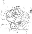
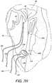
- the human heartrelies on a series of one-way valves to help control the flow of blood through the chambers of the heart.
- deoxygenated bloodreturns to the heart 20 , via the superior vena cava 22 and the inferior vena cava 24 , entering the right atrium 26 .
- the heart muscle tissuecontracts in a rhythmic, coordinated heartbeat, first with an atrial contraction which aids blood in the right atrium 26 to pass through the tricuspid valve 28 and into the right ventricle 30 . Following atrial contraction, ventricular contraction occurs and the tricuspid valve 28 closes.
- Ventricular contractionis stronger than atrial contraction, assisting blood flow through the pulmonic valve 32 , out of the heart 20 via the pulmonary artery 34 , and to the lungs (not shown) for oxygenation.
- the pulmonic valve 32closes, preventing the backwards flow of blood from the pulmonary artery 34 into the heart 20 .
- Left atrial contractionassists blood in the left atrium 38 to pass through the mitral valve 40 and into the left ventricle 42 .
- ensuing ventricular contractioncauses mitral valve 40 closure, and pushes oxygenated blood from the left ventricle 42 through the aortic valve 44 and into the aorta 46 where it then circulates throughout the body.
- prolapse of mitral valve 40is prevented during ventricular contraction by chordae 40 A attached between the mitral valve 40 leaflets and papillary muscles 40 B.
- the aortic valve 44closes, preventing the backwards flow of blood from the aorta 46 into the heart 20 .
- a person's heart valves 28 , 32 , 40 , and 44can have or develop problems which adversely affect their function and, consequently, negatively impact the person's health.
- problems with heart valvescan be organized into two categories: regurgitation and/or stenosis.
- Regurgitationoccurs if a heart valve does not seal tightly, thereby allowing blood to flow back into a chamber rather than advancing through and out of the heart. This can cause the heart to work harder to remain an effective pump. Regurgitation is frequently observed when the mitral valve 40 fails to properly close during a ventricular contraction. Mitral regurgitation can be caused by chordae 40 A stretching, tearing, or rupture, along with other structural changes within the heart.
- Neochordal replacement for stretched or torn chordaeis one option to reduce regurgitation.
- chords to be replacedare identified and dissected as required.
- a papillary sutureis placed in a papillary muscle corresponding to the dissected chord.
- the papillary suturemay optionally be pledgeted on one or both sides of the papillary muscle.
- a leaflet sutureis also placed in the corresponding mitral valve leaflet. The papillary suture and the leaflet suture may then be tied or otherwise fastened together to create a replacement chord to help support the mitral valve leaflet and prevent regurgitation.
- neochordal replacement with ePTFE sutureis a proven method of mitral valve repair
- technical challengesimpede its widespread utilization, especially in minimally invasive cardiac surgery.
- An innovative system that remotely delivers and reliably secures ePTFE suture (or any other desired suture)would dramatically improve the accessibility and clinical outcomes following neochordal implantation.
- a surgical suturing devicehas a forked guide tip having a plurality of legs, wherein each of the plurality of legs comprises a proximal end, an anatomical variation, and a distal end.
- a method of chord replacement for a heart valveis also disclosed.
- a sutureis placed in a papillary muscle using a surgical suturing device having a forked guide tip and a papillary suture.
- a leaflet sutureis placed in a leaflet.
- the papillary suture and the leaflet sutureare loaded in a suture fastener from opposite directions in a coaxial fashion.
- the length of the papillary suture and/or the leaflet sutureare adjusted relative to the suture fastener to achieve a desired replacement chord length.
- the suture fasteneris attached to the papillary suture and the leaflet suture to lock the desired replacement chord length.
- FIG. 1is a cross-sectional view of a heart, illustrating the chambers and valves which function therein.
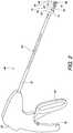
- FIG. 2is a perspective view of one embodiment of a surgical suturing device.
- FIG. 3is an exploded perspective view of the embodied surgical suturing device of FIG. 2 without the housing or needle actuator.
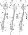
- FIGS. 4A-4Eshow top, front, bottom, left side, and right side views, respectively for one embodiment of a forked guide tip for a surgical suturing device.
- FIG. 5illustrates the forked guide tip of FIG. 4B with one non-limiting embodiment of advantageous and ergonomic dimensions.
- FIGS. 6A-6Cillustrate, in partial cross-sectional view, an example of using one embodiment of a surgical suturing device to place a stitch in tissue, for example, a papillary muscle.
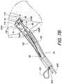
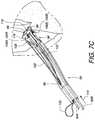
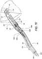
- FIGS. 7A-1 to 7Gillustrate a method of using an embodiment of the surgical suturing device from FIG. 2 to place a suture in a papillary muscle.
- FIGS. 7H-7Iillustrate a method of coupling a first suture placed in a papillary muscle and a second suture placed in a valve leaflet to each other using a mechanical fastener to replace a chordae tendinae of the heart.
- FIGS. 8 and 9illustrate alternate embodiments for using the forked guide tip of FIG. 2 with a pledgeted suture.
- FIGS. 10A-10Billustrate one embodiment of a forked guide tip for a surgical suturing device for placing a double-pledgeted suture in a papillary muscle.
- FIGS. 11A-11Billustrate another embodiment of a forked guide tip for a surgical suturing device for placing a double-pledgeted suture in a papillary muscle.
- FIG. 12illustrates a further embodiment of a forked guide tip for a surgical suturing device.
- FIG. 2is a perspective view of one embodiment of a surgical suturing device 48 .
- the surgical suturing device 48may have a housing 50 coupled to a shaft 52 .
- a forked guide tip 54is coupled to an end of the shaft 52 , opposite from the housing 48 .
- the forked guide tip 54may be continuous with the shaft 52 , rather than a separate assembly piece which is coupled to the shaft 52 .
- the surgical suturing device 48also has a needle actuator 56 which is configured to move two needles (not visible in this view) within the forked guide tip 54 as will be described in greater detail below.
- Suitable shaftsinclude a straight shaft (as illustrated), a curved shaft, a bent shaft, a flexible shaft, and an articulating shaft.
- suitable needle actuatorsinclude a handle (as illustrated), a lever, a knob, a slide, a gear, a wheel, a motor, and a solenoid.
- the forked guide tip 54may have a suture feed opening 58 which can be used to allow a portion of a suture (not shown in this view) to be loaded into at least a portion of the shaft 52 and potentially into and/or out of the housing 50 for the purpose of simplifying suture management.
- the forked guide tip 54may also have one or more cross-supports 60 extending between individual legs 62 , 64 of the forked guide tip 54 .
- a distal end 66 , 68 of each leg 62 , 64 , respectively, of the forked guide tip 54includes a ferrule receiving aperture in alignment with a needle path (not shown in this view, but illustrated farther below) extending from proximal portions 70 , 72 of the respective forked guide tip legs 62 , 64 .
- the fork leg 62includes an anatomical variation 74 .
- the other forked guide tip leg 64has an anatomical variation 76 between its proximal and distal ends 72 , 68 .
- the anatomical variations 74 , 76are sized to help guide the forked guide tip 54 onto one or more anatomical structures.
- the anatomical variations 74 , 76include arches sized and shaped to fit on a papillary muscle.
- the openings between the forked legs 62 , 64help to provide visibility to tissue when the anatomical variations are positioned by a surgeon operating the device, for example by manipulating the housing 50 with the attached handle 78 .
- the forked legs 62 , 64may also be curved away from a longitudinal axis 80 of the shaft 52 to provide added visibility through the forked area.
- the forked legs 62 , 64are curved in a concave fashion with respect to the longitudinal axis 80 passing over them as illustrated in FIG. 2 .
- FIG. 3is an exploded perspective view of the embodied surgical suturing device of FIG. 2 without the housing 50 or needle actuator 56 .
- Two needle guide tubes 82 A, 82 Bare inserted into respective openings 84 A, 84 B in multiple supports 86 .
- the supports 86may be distributed evenly or unevenly along the guide tubes 82 A, 82 B.
- the shaft 52is hollow and the supports 86 are sized to fit into and be supported by the inside of the shaft 52 .
- the forked guide tip 54attaches to the distal end 88 of the shaft 52 such that the needle guide tubes 82 A, 82 B align with needle channels (not visible in this view, but discussed below and shown in FIGS. 4A-4E ) in the forked guide tip 54 .
- Two needles 90 A, 90 Bcan be inserted into respective needle guide tubes 82 A, 82 B as illustrated in FIG. 3 .
- the supports 86can also include a suture passage 85 to allow a portion of a suture (not shown in this view), fed into the shaft 52 via the suture feed opening 58 , to extend either partially into the shaft 52 or all the way through the shaft 52 and into the housing 50 (not shown in this view).
- FIGS. 4A-4Eshow top, front, bottom, left side, and right side views, respectively for one embodiment of a forked guide tip 54 for a surgical suturing device.
- the needle channels 92 A, 92 Bcan be seen passing from the proximal end 94 of the guide tip 54 through the respective legs 62 , 64 of the forked guide tip 54 .
- the distal ends 66 , 68 of the legs 62 , 64each have a respective ferrule receiving aperture 96 A, 96 B which will be discussed in more detail further in this specification.
- the suture feed opening 58can be seen extending through the forked guide tip 54 towards and all the way through the proximal end 94 of the forked guide tip 54 .
- the cross supports 60 and the anatomical variations 74 , 76 discussed previously,are also shown in one or more views of FIGS. 4A-4E .
- FIGS. 4A-4Eshow top, front, bottom, left side, and right side views, respectively for one embodiment of a forked guide tip 54 for a surgical suturing device as described above.
- FIG. 5illustrates a forked guide tip 54 with one non-limiting embodiment of advantageous and ergonomic dimensions.
- the legs 62 , 64have a substantially concave shape with respect to the longitudinal axis 80 of the shaft.
- the needle channel 92 Ahas a proximal channel axis 81 which us approximately 0.204 inches above a tip axis 83 .
- the proximal channel axis 81 and the tip axis 83are substantially parallel.
- the portion of the needle channel 92 A corresponding to the proximal channel axis and the portion of the needle channel 92 A corresponding to the tip axis 83are approximately 1.405 inches apart when measured in a direction parallel to the proximal channel axis 81 .
- the upper curve R 2 of the legs 62 , 64has a radius of approximately 2.775 inches.
- FIGS. 6A-6Cillustrate, in partial cross-sectional view, an example of using one embodiment of a surgical suturing device to place a stitch in tissue, for example, a papillary muscle 108 .
- the side viewillustrates only a single leg 62 , it should be understood that there is a second leg not visible in this view that functions similarly to the shown leg.
- the anatomical variation 74in conjunction with the end of the leg 62 near the anatomical variation 74 and the distal end 112 of the device form a tissue bite area 98 which may be placed over the tissue in question (in this example, a papillary muscle 108 ).
- the distal end 112has a ferrule receiving aperture 96 A into which a ferrule 100 has been positioned.
- the ferrule 100is coupled to a suture 102 which exits from a slot in the distal end 112 of the device.
- the end of the suture 102 opposite the ferrule 100may terminate in a second ferrule (not shown) that is installed in the ferrule receiving aperture of the second leg (which is not visible in this side view.
- the end of the suture 102 opposite the ferrule 100may have nothing attached thereto.
- the suture 102is simply shown as ending at a break line, however, in practice, part of the suture 102 can be fed back through the suture feed opening 58 to help manage the suture 102 .
- sutureis intended to cover any thread, cable, wire, filament, strand, line, yarn, gut, or similar structure, whether natural and/or synthetic, in monofilament, composite filament, or multifilament form (whether braided, woven, twisted, or otherwise held together), as well as equivalents, substitutions, combinations, and pluralities thereof for such materials and structures.
- a needle 90 Ais positioned within needle channel 92 A in a refracted position.
- the needle 90 Ahas a ferrule-engaging tip 106 which is also configured to be able to penetrate tissue 108 .
- an actuator(not shown), coupled to the needle 90 A, moves the needle 90 A in a distal direction 110 , causing the ferrule engaging tip 106 to penetrate the tissue 108 in the tissue bite area 98 as it moves across the tissue bite area 98 and then engages the ferrule 100 held by the ferrule receiving aperture 96 A.
- FIG. 6Ban actuator (not shown), coupled to the needle 90 A, moves the needle 90 A in a distal direction 110 , causing the ferrule engaging tip 106 to penetrate the tissue 108 in the tissue bite area 98 as it moves across the tissue bite area 98 and then engages the ferrule 100 held by the ferrule receiving aperture 96 A.
- the actuatormoves the needle 90 A in a proximal direction 114 , causing the ferrule-engaging tip 106 and the ferrule 100 which is attached to it to be pulled back across the tissue bite area 98 and through the tissue 108 . A portion of the suture 102 is also pulled back through the tissue 108 .
- FIGS. 7A-1 to 7Gillustrate a method of using an embodiment of the surgical suturing device from FIG. 2 to place a suture 102 in a papillary muscle 108 .
- FIG. 7A-1schematically illustrates a surgical situation. Minimally invasive access has been gained to the left ventricle 42 of the heart. Healthy chordae 40 A are coupled between a papillary muscle 40 B and leaflets of the mitral valve 40 . A pathologic chord has been removed from another papillary muscle 108 and the suturing device is ready to be used. For convenience the shaft, handle, and actuator of the surgical device are not illustrated in these views.
- the devicehas a forked guide tip 54 having first and second legs.
- the first leghas a proximal end 70 , an anatomical variation 74 , and a distal end 66 .
- the second leghas a proximal end 72 , an anatomical variation 76 , and a distal end 68 .
- the devicealso has a viewing area 115 defined at least in part by the anatomical variations 74 , 76 of the forked guide tip 54 .
- a first needle 90 Ahaving a suture engaging tip 106 A, resides in the first leg in a refracted position.
- a second needle 90 Bhaving a suture engaging tip 106 B, resides in the second leg in a retracted position.
- a first ferrule 100 Ais held in the distal end 66 of the first leg, while a second ferrule 100 B is held in the distal end 68 of the second leg.
- a suture 102runs from the first ferrule 100 A, through a first hole in a pledget 116 , back into the suture feed opening 58 , reverses back out of the suture feed opening 58 , through a second hole in the pledget 116 , and to the second ferrule 100 B.
- the pledget 116rests on part of one or more of the anatomical variations 74 , 76 . In other embodiments, the pledget 116 may rest on other portions of the device.
- the pledget 116has a first face 118 where the end of suture 102 exit the pledget 116 to couple to the ferrules 100 A, 100 B.
- the tissue bite area 98is placed over the papillary muscle 108 . This can advantageously be done by looking through the viewing area 115 from FIG. 7A-2 .
- the first and second needles 90 A, 90 Bare moved by the actuator (not shown) in a distal direction 110 , causing the ferrule engaging tips 106 A, 106 B to penetrate the tissue 108 in the tissue bite area 98 as they move across the tissue bite area 98 and then engage the respective ferrules 100 A, 100 B held in the distal ends 66 , 68 .
- the actuatornot shown
- the actuatormoves the needles 90 A, 90 B in a proximal direction 114 , causing the ferrule-engaging tips 106 A, 106 B and the respective ferrules 100 A, 100 B which are attached to them to be pulled back through the tissue 108 .
- Portions of the suture 102are also pulled back through the tissue 108 .
- the pledget 116may start to pivot 122 off the end of the device so that the first side 118 of the pledget 116 starts to face the tissue 108 .
- a second side 120 of the pledget 116is located opposite the first side 118 of the pledget 116 .
- the suture 102starts to play out of the suture feed opening 58 .
- the suturing deviceis pulled away 124 from the papillary muscle 108 and the suture 102 may exit the suture feed opening 58 completely.
- the devicemay continue to be withdrawn 126 such that the first side of the pledget 118 contacts the tissue 108 as the approximate midpoint 127 of the suture 102 is pulled against the second side 120 of the pledget 116 .
- the ferrules 100 A, 100 B held by the devicemay then be removed from the ends of the suture 102 .
- the pledgetdoes provide an advantageous interface to help protect the suture stitch from pulling through the tissue.
- the suture ends passing out of the tissue 108may be threaded through a second pledget 128 so both sides of the papillary muscle are pledgeted as illustrated in FIG. 7G .
- FIGS. 7H-7Iillustrate a method of coupling a first suture 102 placed in a papillary muscle 108 (for example, as illustrated in the method of FIGS. 7A-2 to 7G ) and a second suture 130 placed in a valve leaflet 132 to each other using a mechanical fastener to replace a chordae tendinae of the heart.
- FIG. 7Hsimply shows the second suture 130 after it has been stitched through a leaflet 132 of the mitral valve 40 .
- FIG. 7Hsimply shows the second suture 130 after it has been stitched through a leaflet 132 of the mitral valve 40 .
- FIG. 7Iillustrates a mechanical fastener 134 which has been fastened to hold a first set of suture ends 136 of the first suture 102 which have been passed up through the mechanical faster 134 .
- the mechanical fastener 134also holds a second set of suture ends 138 of the second suture 130 which have been passed down through the mechanical fastener 134 .
- One suitable method for fastening the two sets of suture ends together in this fashionis disclosed in U.S. Patent Application Publication 2014/0276979, published Sep. 18, 2014 for U.S. patent application Ser. No. 13/840,481 filed Mar. 15, 2013, the entirety of which is hereby incorporated by reference.
- FIGS. 8 and 9illustrate alternate embodiments for using the forked guide tip of FIG. 2 with a pledgeted suture.
- the forked guide tip 140 embodiment of FIG. 8is similar to previous embodiments, except for the pledget 116 which is rested against a proximal side of the anatomical variations 74 , 76 .
- the viewing area 142is defined between the forked legs 62 , 64 and the proximal portions of the anatomical variations 74 , 76 .
- the forked guide tip embodiment of FIG. 9is similar to previous embodiments, except for the pledget 116 which is rested against the suture feed opening 58 . In this embodiment, the viewing area 146 is potentially much larger without the pledget 116 blocking a portion of the view.
- FIGS. 10A-10Billustrate one embodiment of a forked guide tip 148 for a surgical suturing device for placing a double-pledgeted suture in a papillary muscle.
- the forked guide tip 148is similar to previous embodiments in that it includes a first pledget 150 through which the suture 102 is routed before reaching the ferrules in the distal leg ends 66 , 68 .
- a second pledget 152is held in a pledget holder 154 adjacent to the tissue bite area 98 .
- the second pledget 152is preferably positioned so that the pledget holes are in alignment with the openings in the legs 62 , 64 from which the needles 90 A, 90 B will extend. As illustrated in FIG.
- the needles 90 A, 90 Bmay be advanced 156 out of the legs, through the second pledget 152 , across the tissue bite area 98 and into engagement with the ferrules. When the ferrules and suture are pulled back through the tissue bite area, they will then be pulled through the second pledget, thereby double-pledgeting the tissue sutured by the device.
- FIGS. 11A-11Billustrate another embodiment of a forked guide tip 158 for a surgical suturing device for placing a double-pledgeted suture in a papillary muscle.
- the forked guide tip 158is similar to the embodiment of FIG. 10A , except that it also includes pledget hole stabilizers 160 A, 160 B on the tissue gap 98 side of the pledget holder 154 . Since the needles 90 A, 90 B may tend to push the second pledget 152 out of the pledget holder 154 in some embodiments as they pass through the second pledget 152 , the pledget hole stabilizers 160 A, 160 B may help prevent the movement of the second pledget away from the needles 90 A, 90 B.
- the pledget hole stabilizers 160 A, 160 Bmay also enable the use of a second pledget 152 which does not have pre-formed holes, since the needles 90 A, 90 B will be able to pierce the second pledget as it held in place by the pledget holder 154 and the pledget hole stabilizers 160 A, 160 B.
- the needles 90 A, 90 Bmay be advanced 162 out of the legs 62 , 64 , through the second pledget 152 , through the pledget hole stabilizers 160 A, 160 B, across the tissue bite area 98 and into engagement with the ferrules held in the distal ends 66 , 68 .
- the ferrules and sutureare pulled back through the tissue bite area 98 , they will then be pulled through the second pledget, thereby double-pledgeting the tissue sutured by the device.
- FIG. 12illustrates a further embodiment of a forked guide tip 164 for a surgical suturing device.
- the embodiment of FIG. 12is similar to previous embodiments, particularly the embodiment of FIG. 2 , however it does not include any cross supports.
- the forked guide tip 164has first and second legs 166 , 168 which are coupled to their respective distal ends 66 , 68 by respective first and second anatomical variations 170 , 172 .
- a viewing area 174is defined by the combination on one side of the first leg 166 , the first anatomical variation 170 , and the first distal end 66 and by the combination on the other side of the second leg 168 , the second anatomical variation 172 , and the second distal end 68 .
Landscapes
- Health & Medical Sciences (AREA)
- Life Sciences & Earth Sciences (AREA)
- Surgery (AREA)
- Veterinary Medicine (AREA)
- Cardiology (AREA)
- Biomedical Technology (AREA)
- Heart & Thoracic Surgery (AREA)
- Engineering & Computer Science (AREA)
- Public Health (AREA)
- Animal Behavior & Ethology (AREA)
- General Health & Medical Sciences (AREA)
- Molecular Biology (AREA)
- Nuclear Medicine, Radiotherapy & Molecular Imaging (AREA)
- Medical Informatics (AREA)
- Oral & Maxillofacial Surgery (AREA)
- Transplantation (AREA)
- Vascular Medicine (AREA)
- Rheumatology (AREA)
- Surgical Instruments (AREA)
Abstract
Description
Claims (16)
Priority Applications (3)
| Application Number | Priority Date | Filing Date | Title |
|---|---|---|---|
| US14/716,803US10736624B2 (en) | 2014-05-19 | 2015-05-19 | Minimally invasive surgical suturing device for papillary muscles and methods thereof |
| EP16797289.2AEP3297540B1 (en) | 2015-05-19 | 2016-05-19 | Minimally invasive surgical suturing device for papillary muscles |
| PCT/US2016/033234WO2016187406A1 (en) | 2015-05-19 | 2016-05-19 | Minimally invasive surgical suturing device for papillary muscles and methods thereof |
Applications Claiming Priority (2)
| Application Number | Priority Date | Filing Date | Title |
|---|---|---|---|
| US201462000280P | 2014-05-19 | 2014-05-19 | |
| US14/716,803US10736624B2 (en) | 2014-05-19 | 2015-05-19 | Minimally invasive surgical suturing device for papillary muscles and methods thereof |
Publications (2)
| Publication Number | Publication Date |
|---|---|
| US20150359531A1 US20150359531A1 (en) | 2015-12-17 |
| US10736624B2true US10736624B2 (en) | 2020-08-11 |
Family
ID=54835174
Family Applications (1)
| Application Number | Title | Priority Date | Filing Date |
|---|---|---|---|
| US14/716,803Active2036-11-06US10736624B2 (en) | 2014-05-19 | 2015-05-19 | Minimally invasive surgical suturing device for papillary muscles and methods thereof |
Country Status (1)
| Country | Link |
|---|---|
| US (1) | US10736624B2 (en) |
Cited By (6)
| Publication number | Priority date | Publication date | Assignee | Title |
|---|---|---|---|---|
| US20210145433A1 (en)* | 2010-11-23 | 2021-05-20 | Medos International Sàrl | Surgical filament snare assemblies |
| US12310573B2 (en) | 2012-05-07 | 2025-05-27 | Medos International Sàrl | Systems, devices, and methods for securing tissue using snare assemblies and soft anchors |
| US12336700B2 (en) | 2012-05-07 | 2025-06-24 | Medos International Sarl | Systems, devices, and methods for securing tissue |
| US12357294B2 (en) | 2010-11-23 | 2025-07-15 | Medos International Sàrl | Surgical filament snare assemblies |
| US12369902B2 (en) | 2012-09-20 | 2025-07-29 | Medos International Sàrl | Systems, devices, and methods for securing tissue using hard anchors |
| US12402874B2 (en) | 2013-03-15 | 2025-09-02 | Medos International Sàrl | Surgical constructs with collapsing suture loop and methods for securing tissue |
Families Citing this family (22)
| Publication number | Priority date | Publication date | Assignee | Title |
|---|---|---|---|---|
| EP1909655A2 (en) | 2005-06-20 | 2008-04-16 | Sutura, Inc. | Method and apparatus for applying a knot to a suture |
| US8246636B2 (en) | 2007-03-29 | 2012-08-21 | Nobles Medical Technologies, Inc. | Suturing devices and methods for closing a patent foramen ovale |
| US8771296B2 (en) | 2008-05-09 | 2014-07-08 | Nobles Medical Technologies Inc. | Suturing devices and methods for suturing an anatomic valve |
| EP3644194B1 (en) | 2011-04-15 | 2022-12-07 | Heartstitch, Inc. | Suturing devices for suturing an anatomic valve |
| US9706988B2 (en) | 2012-05-11 | 2017-07-18 | Heartstitch, Inc. | Suturing devices and methods for suturing an anatomic structure |
| WO2015002815A1 (en) | 2013-07-02 | 2015-01-08 | Med-Venture Investments, Llc | Suturing devices and methods for suturing an anatomic structure |
| JP6469109B2 (en) | 2013-12-06 | 2019-02-13 | メッド − ベンチャー インベストメンツ、エルエルシー | Suture method and apparatus |
| US10178993B2 (en) | 2014-07-11 | 2019-01-15 | Cardio Medical Solutions, Inc. | Device and method for assisting end-to-side anastomosis |
| GB2536538B (en) | 2014-09-17 | 2018-07-18 | Cardiomech As | Anchor for implantation in body tissue |
| US10016189B2 (en)* | 2014-12-15 | 2018-07-10 | Lsi Solutions, Inc. | Surgical rib retractor and methods thereof |
| WO2017180092A1 (en) | 2016-04-11 | 2017-10-19 | Nobles Medical Technologies Ii, Inc. | Suture spools for tissue suturing device |
| US10898181B2 (en) | 2017-03-17 | 2021-01-26 | Cypris Medical, Inc. | Suturing system |
| EP4115818A3 (en) | 2017-06-19 | 2023-04-05 | Heartstitch, Inc. | Suturing systems and methods for suturing body tissue |
| EP3641660B1 (en) | 2017-06-19 | 2024-11-20 | Heartstitch, Inc. | Suturing devices for suturing an opening in the apex of the heart |
| EP3668415B1 (en) | 2017-08-18 | 2023-10-25 | Nobles Medical Technologies II, Inc. | Apparatus for applying a knot to a suture |
| WO2019051379A1 (en)* | 2017-09-11 | 2019-03-14 | Heartstitch, Inc. | Methods and devices for papillary suturing |
| US10660637B2 (en) | 2018-04-06 | 2020-05-26 | Cypris Medical, Inc. | Suturing system |
| US11033261B2 (en) | 2018-05-31 | 2021-06-15 | Cypris Medical, Inc. | Suture system |
| US11224418B2 (en) | 2018-06-15 | 2022-01-18 | Edwards Lifesciences Corporation | Papillary muscle approximation pads |
| US11357500B2 (en)* | 2018-09-12 | 2022-06-14 | Lsi Solutions, Inc. | Surgical suturing device for repair of tricuspid regurgitation and methods thereof |
| US20220015906A1 (en) | 2018-11-29 | 2022-01-20 | Cardiomech As | Device for Heart Repair |
| US12137899B2 (en)* | 2020-05-11 | 2024-11-12 | Cypris Medical, Inc. | Multiple suture placement system |
Citations (19)
| Publication number | Priority date | Publication date | Assignee | Title |
|---|---|---|---|---|
| US5431666A (en) | 1994-02-24 | 1995-07-11 | Lasersurge, Inc. | Surgical suture instrument |
| US5562686A (en) | 1995-04-19 | 1996-10-08 | United States Surgical Corporation | Apparaus and method for suturing body tissue |
| WO1998053745A1 (en) | 1997-05-27 | 1998-12-03 | United States Surgical Corporation | Stitching devices for heart valve replacement surgery |
| US20030236535A1 (en)* | 2002-05-08 | 2003-12-25 | Olympus Optical Co., Ltd. | Apparatus for ligating/suturing living tissues and system for resecting/suturing living tissues |
| US20040133238A1 (en) | 1999-06-22 | 2004-07-08 | Cerier Jeffrey C. | Tissue fixation devices and methods of fixing tissue |
| US20050119735A1 (en) | 2002-10-21 | 2005-06-02 | Spence Paul A. | Tissue fastening systems and methods utilizing magnetic guidance |
| US20050251153A1 (en)* | 2004-04-07 | 2005-11-10 | Pankaj Jay Pasricha | Ligature and suture device for medical application, ligature and suture system for medical application, and ligaturing and suturing method for medical application |
| US6997931B2 (en) | 2001-02-02 | 2006-02-14 | Lsi Solutions, Inc. | System for endoscopic suturing |
| US20070100348A1 (en)* | 1999-10-20 | 2007-05-03 | Cauthen Joseph C Iii | Apparatus and methods for the treatment of the intervertebral disc |
| US20080065120A1 (en) | 2005-10-31 | 2008-03-13 | Zannis Anthony D | Surgical instrument, kit and method for creating mattress-type stitches |
| US7407505B2 (en) | 2004-01-14 | 2008-08-05 | Lsi Solutions, Inc. | Running stitch suturing device |
| US20090222027A1 (en) | 2008-02-28 | 2009-09-03 | Lsi Solutions, Inc. | Ferrule holder with suture relief lobes |
| US7731727B2 (en) | 2006-04-26 | 2010-06-08 | Lsi Solutions, Inc. | Medical instrument to place a pursestring suture, open a hole and pass a guidewire |
| US20110306989A1 (en) | 2010-06-09 | 2011-12-15 | C.R. Bard, Inc. | Instruments for delivering transfascial sutures, transfascial suture assemblies, and methods of transfascial suturing |
| US20120016383A1 (en)* | 2010-07-13 | 2012-01-19 | Lsi Solutions, Inc. | Method and apparatus for closing an opening in thick, moving tissue |
| US8313496B2 (en) | 2001-02-02 | 2012-11-20 | Lsi Solutions, Inc. | System for endoscopic suturing |
| US8398657B2 (en) | 2009-11-19 | 2013-03-19 | Lsi Solutions, Inc. | Multi-fire suturing instrument with proximal ferrule release feature |
| US20150282805A1 (en)* | 2014-04-08 | 2015-10-08 | Lsi Solutions, Inc. | Surgical suturing device for a replacement anatomical structure and methods thereof |
| WO2016118869A1 (en) | 2015-01-23 | 2016-07-28 | Boston Scientific Scimed, Inc. | Balloon catheter visualization systems, methods, and devices having pledgets |
- 2015
- 2015-05-19USUS14/716,803patent/US10736624B2/enactiveActive
Patent Citations (19)
| Publication number | Priority date | Publication date | Assignee | Title |
|---|---|---|---|---|
| US5431666A (en) | 1994-02-24 | 1995-07-11 | Lasersurge, Inc. | Surgical suture instrument |
| US5562686A (en) | 1995-04-19 | 1996-10-08 | United States Surgical Corporation | Apparaus and method for suturing body tissue |
| WO1998053745A1 (en) | 1997-05-27 | 1998-12-03 | United States Surgical Corporation | Stitching devices for heart valve replacement surgery |
| US20040133238A1 (en) | 1999-06-22 | 2004-07-08 | Cerier Jeffrey C. | Tissue fixation devices and methods of fixing tissue |
| US20070100348A1 (en)* | 1999-10-20 | 2007-05-03 | Cauthen Joseph C Iii | Apparatus and methods for the treatment of the intervertebral disc |
| US8313496B2 (en) | 2001-02-02 | 2012-11-20 | Lsi Solutions, Inc. | System for endoscopic suturing |
| US6997931B2 (en) | 2001-02-02 | 2006-02-14 | Lsi Solutions, Inc. | System for endoscopic suturing |
| US20030236535A1 (en)* | 2002-05-08 | 2003-12-25 | Olympus Optical Co., Ltd. | Apparatus for ligating/suturing living tissues and system for resecting/suturing living tissues |
| US20050119735A1 (en) | 2002-10-21 | 2005-06-02 | Spence Paul A. | Tissue fastening systems and methods utilizing magnetic guidance |
| US7407505B2 (en) | 2004-01-14 | 2008-08-05 | Lsi Solutions, Inc. | Running stitch suturing device |
| US20050251153A1 (en)* | 2004-04-07 | 2005-11-10 | Pankaj Jay Pasricha | Ligature and suture device for medical application, ligature and suture system for medical application, and ligaturing and suturing method for medical application |
| US20080065120A1 (en) | 2005-10-31 | 2008-03-13 | Zannis Anthony D | Surgical instrument, kit and method for creating mattress-type stitches |
| US7731727B2 (en) | 2006-04-26 | 2010-06-08 | Lsi Solutions, Inc. | Medical instrument to place a pursestring suture, open a hole and pass a guidewire |
| US20090222027A1 (en) | 2008-02-28 | 2009-09-03 | Lsi Solutions, Inc. | Ferrule holder with suture relief lobes |
| US8398657B2 (en) | 2009-11-19 | 2013-03-19 | Lsi Solutions, Inc. | Multi-fire suturing instrument with proximal ferrule release feature |
| US20110306989A1 (en) | 2010-06-09 | 2011-12-15 | C.R. Bard, Inc. | Instruments for delivering transfascial sutures, transfascial suture assemblies, and methods of transfascial suturing |
| US20120016383A1 (en)* | 2010-07-13 | 2012-01-19 | Lsi Solutions, Inc. | Method and apparatus for closing an opening in thick, moving tissue |
| US20150282805A1 (en)* | 2014-04-08 | 2015-10-08 | Lsi Solutions, Inc. | Surgical suturing device for a replacement anatomical structure and methods thereof |
| WO2016118869A1 (en) | 2015-01-23 | 2016-07-28 | Boston Scientific Scimed, Inc. | Balloon catheter visualization systems, methods, and devices having pledgets |
Non-Patent Citations (3)
| Title |
|---|
| Jan. 21, 2019 Extended European Search Report; Mathis, Martin, Extended European Search Report for EP16797289. |
| Sep. 16, 2016 International Search Report; PCT-Written Opinion of the International Searching Authority in corresponding International Application No. PCT/US2016/033234. |
| Sep. 16, 2016 International Search Report; PCT—Written Opinion of the International Searching Authority in corresponding International Application No. PCT/US2016/033234. |
Cited By (7)
| Publication number | Priority date | Publication date | Assignee | Title |
|---|---|---|---|---|
| US20210145433A1 (en)* | 2010-11-23 | 2021-05-20 | Medos International Sàrl | Surgical filament snare assemblies |
| US12329371B2 (en)* | 2010-11-23 | 2025-06-17 | Medos International Sarl | Surgical filament snare assemblies |
| US12357294B2 (en) | 2010-11-23 | 2025-07-15 | Medos International Sàrl | Surgical filament snare assemblies |
| US12310573B2 (en) | 2012-05-07 | 2025-05-27 | Medos International Sàrl | Systems, devices, and methods for securing tissue using snare assemblies and soft anchors |
| US12336700B2 (en) | 2012-05-07 | 2025-06-24 | Medos International Sarl | Systems, devices, and methods for securing tissue |
| US12369902B2 (en) | 2012-09-20 | 2025-07-29 | Medos International Sàrl | Systems, devices, and methods for securing tissue using hard anchors |
| US12402874B2 (en) | 2013-03-15 | 2025-09-02 | Medos International Sàrl | Surgical constructs with collapsing suture loop and methods for securing tissue |
Also Published As
| Publication number | Publication date |
|---|---|
| US20150359531A1 (en) | 2015-12-17 |
Similar Documents
| Publication | Publication Date | Title |
|---|---|---|
| US10736624B2 (en) | Minimally invasive surgical suturing device for papillary muscles and methods thereof | |
| US12070205B2 (en) | Surgical suturing device for a replacement anatomical structure and methods thereof | |
| US20240122712A1 (en) | Translation catheters, systems, and methods of use thereof | |
| US11832810B2 (en) | Suturing device for minimally invasive surgery and needles and methods thereof | |
| US12285173B2 (en) | Systems and methods for left atrial appendage closure | |
| US10835233B2 (en) | Suturing backstop for minimally invasive surgery | |
| US11918204B2 (en) | Suturing device for minimally invasive surgery and needles and methods thereof | |
| EP3297540B1 (en) | Minimally invasive surgical suturing device for papillary muscles | |
| US11337688B2 (en) | Suturing device for minimally invasive surgery and needles and methods thereof |
Legal Events
| Date | Code | Title | Description |
|---|---|---|---|
| AS | Assignment | Owner name:LSI SOLUTIONS, INC., NEW YORK Free format text:ASSIGNMENT OF ASSIGNORS INTEREST;ASSIGNOR:SAUER, MD, JUDE S.;REEL/FRAME:036862/0642 Effective date:20151022 | |
| STPP | Information on status: patent application and granting procedure in general | Free format text:NON FINAL ACTION MAILED | |
| STPP | Information on status: patent application and granting procedure in general | Free format text:RESPONSE TO NON-FINAL OFFICE ACTION ENTERED AND FORWARDED TO EXAMINER | |
| STPP | Information on status: patent application and granting procedure in general | Free format text:FINAL REJECTION MAILED | |
| STPP | Information on status: patent application and granting procedure in general | Free format text:DOCKETED NEW CASE - READY FOR EXAMINATION | |
| STPP | Information on status: patent application and granting procedure in general | Free format text:NON FINAL ACTION MAILED | |
| STPP | Information on status: patent application and granting procedure in general | Free format text:RESPONSE TO NON-FINAL OFFICE ACTION ENTERED AND FORWARDED TO EXAMINER | |
| STPP | Information on status: patent application and granting procedure in general | Free format text:PUBLICATIONS -- ISSUE FEE PAYMENT RECEIVED | |
| STCF | Information on status: patent grant | Free format text:PATENTED CASE | |
| FEPP | Fee payment procedure | Free format text:ENTITY STATUS SET TO UNDISCOUNTED (ORIGINAL EVENT CODE: BIG.); ENTITY STATUS OF PATENT OWNER: LARGE ENTITY | |
| MAFP | Maintenance fee payment | Free format text:PAYMENT OF MAINTENANCE FEE, 4TH YEAR, LARGE ENTITY (ORIGINAL EVENT CODE: M1551); ENTITY STATUS OF PATENT OWNER: LARGE ENTITY Year of fee payment:4 |