US10735105B2 - High power and data delivery in a communications network with safety and fault protection - Google Patents
High power and data delivery in a communications network with safety and fault protectionDownload PDFInfo
- Publication number
- US10735105B2 US10735105B2US15/971,729US201815971729AUS10735105B2US 10735105 B2US10735105 B2US 10735105B2US 201815971729 AUS201815971729 AUS 201815971729AUS 10735105 B2US10735105 B2US 10735105B2
- Authority
- US
- United States
- Prior art keywords
- power
- network device
- high voltage
- cable
- data
- Prior art date
- Legal status (The legal status is an assumption and is not a legal conclusion. Google has not performed a legal analysis and makes no representation as to the accuracy of the status listed.)
- Active
Links
Images


Classifications
- H—ELECTRICITY
- H04—ELECTRIC COMMUNICATION TECHNIQUE
- H04L—TRANSMISSION OF DIGITAL INFORMATION, e.g. TELEGRAPHIC COMMUNICATION
- H04L12/00—Data switching networks
- H04L12/02—Details
- H04L12/10—Current supply arrangements
- H—ELECTRICITY
- H02—GENERATION; CONVERSION OR DISTRIBUTION OF ELECTRIC POWER
- H02H—EMERGENCY PROTECTIVE CIRCUIT ARRANGEMENTS
- H02H1/00—Details of emergency protective circuit arrangements
- H02H1/0007—Details of emergency protective circuit arrangements concerning the detecting means
- H—ELECTRICITY
- H02—GENERATION; CONVERSION OR DISTRIBUTION OF ELECTRIC POWER
- H02J—CIRCUIT ARRANGEMENTS OR SYSTEMS FOR SUPPLYING OR DISTRIBUTING ELECTRIC POWER; SYSTEMS FOR STORING ELECTRIC ENERGY
- H02J1/00—Circuit arrangements for DC mains or DC distribution networks
- H—ELECTRICITY
- H04—ELECTRIC COMMUNICATION TECHNIQUE
- H04B—TRANSMISSION
- H04B10/00—Transmission systems employing electromagnetic waves other than radio-waves, e.g. infrared, visible or ultraviolet light, or employing corpuscular radiation, e.g. quantum communication
- H04B10/07—Arrangements for monitoring or testing transmission systems; Arrangements for fault measurement of transmission systems
- H04B10/075—Arrangements for monitoring or testing transmission systems; Arrangements for fault measurement of transmission systems using an in-service signal
- H04B10/077—Arrangements for monitoring or testing transmission systems; Arrangements for fault measurement of transmission systems using an in-service signal using a supervisory or additional signal
- H04B10/0779—Monitoring line transmitter or line receiver equipment
- H—ELECTRICITY
- H04—ELECTRIC COMMUNICATION TECHNIQUE
- H04B—TRANSMISSION
- H04B10/00—Transmission systems employing electromagnetic waves other than radio-waves, e.g. infrared, visible or ultraviolet light, or employing corpuscular radiation, e.g. quantum communication
- H04B10/80—Optical aspects relating to the use of optical transmission for specific applications, not provided for in groups H04B10/03 - H04B10/70, e.g. optical power feeding or optical transmission through water
- H04B10/806—Arrangements for feeding power
- H04B10/808—Electrical power feeding of an optical transmission system
- H—ELECTRICITY
- H04—ELECTRIC COMMUNICATION TECHNIQUE
- H04L—TRANSMISSION OF DIGITAL INFORMATION, e.g. TELEGRAPHIC COMMUNICATION
- H04L12/00—Data switching networks
- H04L12/28—Data switching networks characterised by path configuration, e.g. LAN [Local Area Networks] or WAN [Wide Area Networks]
- H04L12/40—Bus networks
- H04L12/40006—Architecture of a communication node
- H04L12/40032—Details regarding a bus interface enhancer
Definitions
- the present disclosurerelates generally to communications networks, and more particularly, to safety and fault protection in a communications network with combined high power and data delivery.
- PoEPower over Ethernet
- PSEpower sourcing equipment
- PDpowered device
- PoEPower over Ethernet
- PSEpower sourcing equipment
- PDpowered device
- PoEpower is delivered over the cables used by the data over a range from a few meters to about one hundred meters.
- PSEpower sourcing equipment
- PDpowered device
- PoEpower must be supplied through a local power source such as a wall outlet due to limitations with conventional PoE.
- today's PoE systemshave limited power capacity, which may be inadequate for many classes of devices.
- FIG. 1illustrates an example of a network in which embodiments described herein may be implemented.
- FIG. 2depicts an example of a network device useful in implementing embodiments described herein.
- FIG. 3is a block diagram illustrating components of a power safety and fault protection system, in accordance with one embodiment.
- FIG. 4is a flowchart illustrating an overview of a process for low voltage startup with fault detection and digital interlock in a combined power and data delivery system, in accordance with one embodiment.
- FIG. 5is a flowchart illustrating an overview of a process for pulse power with fault detection between pulses in a combined power and data delivery system, in accordance with one embodiment.
- FIG. 6is a diagram illustrating a circuit for use with pulse load current and auto-negotiation, in accordance with one embodiment.
- FIG. 7is a timing diagram for the circuit shown in FIG. 6 , in accordance with one embodiment.
- FIG. 8is a diagram illustrating a circuit for use with unipolar pulse power and auto-negotiation, in accordance with one embodiment.
- FIG. 9is a timing diagram for the circuit shown in FIG. 8 , in accordance with one embodiment.
- FIG. 10is a diagram illustrating a circuit for use with bipolar pulse power and auto-negotiation, in accordance with one embodiment.
- FIG. 11is a timing diagram for the circuit shown in FIG. 10 , in accordance with one embodiment.
- FIG. 12is a diagram illustrating line-to-ground fault detection, in accordance with one embodiment.
- FIG. 13is a diagram illustrating line-to-line fault detection, in accordance with one embodiment.
- FIG. 14is a diagram illustrating line-to-line fault detection, in accordance with another embodiment.
- FIG. 15is a diagram illustrating line-to-line fault detection, in accordance with yet another embodiment.
- a methodincludes receiving power at an optical transceiver module at a remote network device on a cable delivering power and data from a central network device, operating the remote network device in a low voltage mode during fault sensing at the remote network device, transmitting on the cable, a data signal to the central network device, the data signal indicating an operating status based on the fault sensing, and receiving high voltage power from the central network device on the cable at the remote network device upon transmitting an indication of a safe operating status of the remote network device, wherein the remote network device is powered by the high voltage power.
- a methodgenerally comprises delivering high voltage direct current (HVDC) pulse power from power sourcing equipment to a powered device over a cable delivering power and optical data, testing a power circuit between the power sourcing equipment and the powered device between pulses, and communicating with the powered device over the cable to identify an operating mode at the powered device based on the testing.
- HVDChigh voltage direct current
- an apparatusgenerally comprises an optical interface for receiving optical signals on an optical fiber in a power and data cable at an optical transceiver, an electrical interface for receiving power on an electrical wire in the power and data cable at the optical transceiver for powering the apparatus in a high power mode, and a power module for testing a power circuit and delivering data comprising an operating status of the power circuit over the power and data cable to a combined power and data source.
- the power moduleis configured for testing the power circuit in a low voltage power mode.
- PoEPower over Ethernet
- fiber optic cablingis used to deliver data and when larger power delivery ratings are needed, power is supplied to a remote device through a local power source.
- power and data delivery systemsmay be designed to carry higher data rates and higher power delivery (and may also carry integrated thermal management cooling) combined into a single cable, as described in U.S. patent application Ser. No. 15/910,203 (“Combined Power, Data, and Cooling Delivery in a Communications Network”), filed Mar. 2, 2018, which is incorporated herein by reference in its entirety.
- These connectionsmay be point-to-point, such as from a central hub to one or more remote devices (e.g., full hub and spoke layout).
- a single combined function cablemay run most of the way to a cluster of powered devices and then split, as described in U.S. patent application Ser. No.
- fault sensingis performed through a low voltage safety check combined with a digital interlock that uses the data system to provide feedback on the power system status and set a power operation mode.
- the fault sensingmay be performed, for example, during a low voltage startup or between high power pulses in a pulse power system.
- the pulse powermay comprise source voltage pulse power (unipolar or bipolar) or load current pulse power with low voltage fault detection between high voltage power pulses.
- Fault sensingmay include, for example, line-to-line fault detection with low voltage sensing of the cable or powered device and line-to-ground fault detection with midpoint grounding.
- Touch-safe fault protectionmay also be provided through cable and connector designs that are touch-safe even with high voltage applied.
- the power safety featuresprovide for safe system operation and installation and removal (disconnect) of components.
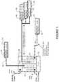
- FIG. 1an example of a network in which embodiments described herein may be implemented is shown. For simplification, only a small number of nodes are shown.
- the embodimentsoperate in the context of a data communications network including multiple network devices.
- the networkmay include any number of network devices in communication via any number of nodes (e.g., routers, switches, gateways, controllers, access points, or other network devices), which facilitate passage of data within the network.
- nodese.g., routers, switches, gateways, controllers, access points, or other network devices
- the network devicesmay communicate over or be in communication with one or more networks (e.g., local area network (LAN), metropolitan area network (MAN), wide area network (WAN), virtual private network (VPN) (e.g., Ethernet virtual private network (EVPN), layer 2 virtual private network (L2VPN)), virtual local area network (VLAN), wireless network, enterprise network, corporate network, data center, Internet of Things (IoT) network, Internet, intranet, or any other network).
- networkse.g., local area network (LAN), metropolitan area network (MAN), wide area network (WAN), virtual private network (VPN) (e.g., Ethernet virtual private network (EVPN), layer 2 virtual private network (L2VPN)), virtual local area network (VLAN), wireless network, enterprise network, corporate network, data center, Internet of Things (IoT) network, Internet, intranet, or any other network).
- networkse.g., local area network (LAN), metropolitan area network (MAN), wide area network (WAN), virtual private network (VPN) (e.g., Ethernet virtual
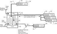
- the networkis configured to pass electrical power along with data to provide both data connectivity and electric power to network devices such as switches 14 , routers, access points 15 , or other electronic components and devices. Signals may be exchanged among communications equipment and power transmitted from power sourcing equipment (PSE) 10 to powered devices (PDs) 14 , 15 .
- PSEpower sourcing equipment
- PDspowered devices
- the advanced power over data systemdelivers power to and from a network (e.g., switch/router system) using an interface module 16 (e.g., optical transceiver module) configured to receive and transmit both data (fiber delivered data) and electrical power (high power energy).
- an interface module 16e.g., optical transceiver module
- the power and datamay be delivered over a cable comprising both optical fibers and electrical wires (e.g., copper wires), as described in U.S. patent application Ser. No. 15/707,976 (“Power Delivery Through an Optical System”), filed Sep. 18, 2017, which is incorporated herein by reference in its entirety.
- the systemmay further provide cooling and deliver combined power, data, and cooling within a single hybrid cable system, as described, for example, in U.S. patent application Ser. Nos. 15/910,203 and 15/918,972, referenced above.
- the advanced power over data systemmay use building power supplied to a central network device (hub) (e.g., PSE) 10 , which may be located in a premise/entry room, for example.
- the powermay be transmitted from the building entry point to end points (switches 14 , access points 15 ), which may be located at distances greater than 100 meters (e.g., 1 km (kilometer), 10 km, or any other distance), and/or at greater power levels than 100 W (watts) (e.g., 250 W, 500 W, 1000 W, 2000 W or any other power level).
- the central network device 10comprises a power supply unit (PSU) 11 for receiving and distributing power (e.g., building power from a power grid, renewable energy source, generator, or battery) and a network interface (e.g., fabric 12 , line cards 13 ).
- PSUpower supply unit
- network interfacee.g., fabric 12 , line cards 13 .
- line card Areceives data from outside of the building (e.g., from street or other location) and line cards B, C, and D distribute power and data.
- the central hub (combined power and data source) 10is operable to provide high capacity power from an internal power system (e.g., PSU 11 capable of delivering power over and including 5 kW, 100 kW, etc., and driving the plurality of devices 14 , 15 , each in the 100 W-3000 W range (e.g., 100 W or greater, 900 W or greater, 1000 W or greater), or any other suitable power range.
- the PSU 11may provide, for example, PoE (Power over Ethernet), PoF (Power over Fiber), HVDC (high voltage direct current), pulse power HVDC, or AC (alternating current).
- the central network device 10is operable to receive external power and transmit power over combined delivery power and data cables 18 in the communications network (e.g., network comprising central hub 10 (PSE) and a plurality of network devices 14 , 15 (PDs)).
- the central network device 10may comprise, for example, a router, convergence system, or any other suitable line card system. It is to be understood that this is only an example and any other network device operable to transmit power and optical data may be used.
- One or more of the line cards 13may also include an interface module 16 (shown at the remote network devices 14 , 15 ) operable to transmit power and data on the cables 18 .
- the networkmay include any number or arrangement of network communications devices (e.g., switches 14 , access points 15 , routers, or other devices operable to route (switch, forward) data communications).
- the networkcomprises a plurality of groups of access points 15 , with each group located on a different floor or zone.
- One or more of the network devices 14 , 15may also deliver power to equipment using PoE.
- one or more of the network devices 14 , 15may deliver power using PoE to electronic components such as IP (Internet Protocol) cameras, VoIP (Voice over IP) phones, video cameras, point-of-sale devices, security access control devices, residential devices, building automation devices, industrial automation devices, factory equipment, lights (building lights, streetlights), traffic signals, fog nodes, IoT devices, sensors, and many other electrical components and devices.
- IPInternet Protocol
- VoIPVoice over IP
- security access control devicesresidential devices, building automation devices, industrial automation devices, factory equipment, lights (building lights, streetlights), traffic signals, fog nodes, IoT devices, sensors, and many other electrical components and devices.
- a redundant central hubmay provide backup or additional power or bandwidth, as needed in the network.
- the remote network device 14 , 15would include another interface module 16 for connection with another cable 18 delivering power and data from the redundant central hub.
- the central hub 10may deliver power and data directly to each network device 14 (point-to-point connection as shown for the switches 14 connected to line cards B and D in FIG. 1 ) or one or more splitting devices (not shown) may be used to connect a plurality of network devices and allow the network to go beyond point-to-point topologies and build passive stars, busses, tapers, multi-layer trees, etc.
- a single long cable 18may run to a conveniently located intermediary splitter device (e.g., passive splitter) servicing a cluster of physically close endpoint devices (e.g., access points 15 connected to line card C in FIG. 1 ).
- One or more control systems for the power and datamay interact between the central hub 10 and the remote devices 15 (and their interface modules 16 ) to ensure that each device receives its fair share of each resource from the splitting device, as described in U.S. patent application Ser. No. 15/918,972, referenced above.
- Cables (combined cable, multi-function cable, multi-use cable, hybrid cable) 18 extending from the network device 10 to the switches 14 and access points 15are configured to transmit power and data, and include both optical fibers and electrical wires.
- the cable 18may include, for example, two power lines (conductors) and two data lines (optical fibers). It is to be understood that that this is only an example and the cable 18 may contain any number of power or data lines.
- a bidirectional optical systemmay be utilized with one wavelength of light going downstream (from central hub 10 to remote device 14 , 15 ) and a different wavelength of light going upstream (from remote device 14 , 15 to central hub 10 ), thereby reducing the fiber count in the cable from two to one.
- the cable 18may also include additional optical fibers or power lines.
- the cables 18may be formed from any material suitable to carry both electrical power and optical data (e.g., copper, fiber) and may carry any number of electrical wires and optical fibers in any arrangement.
- the cables 18may also carry cooling for thermal management of the remote network communications devices 14 , 15 .
- the cables 18 extending from the central hub 10 to the remote network devices 14 , 15may be configured to transmit combined delivery power, data, and cooling in a single cable.
- the cables 18may be formed from any material suitable to carry electrical power, data (e.g., copper, fiber), and coolant (liquid, gas, or multi-phase) and may carry any number of electrical wires, optical fibers, and cooling tubes in any arrangement.
- the cables 18comprise a connector at each end configured to couple with the interface module 16 at the network devices 10 , 14 , 15 .
- the connectormay comprise, for example, a combined power and data connector (hybrid copper and fiber) configured to connect to an optical transceiver, as described in U.S. patent application Ser. No. 15/707,976, referenced above.
- the connectormay comprise, for example, a modified RJ-45 type connector.
- the connector and cable 18are configured to meet standard safety requirements for line-to-ground protection and line-to-line protection at relevant high voltage by means including clearance and creepage distances, and touch-safe techniques.
- the connectormay comprise safety features, including, for example, short-pin for hot-plug and hot-unplug without current surge or interruption for connector arcing protection.
- the connectormay further include additional insulation material for hot-plug and hot-unplug with current surge or interruption with arc-flash protection and reliability life with arcing.
- the insulated cable power connector terminalsare preferably configured to meet touch voltage or current accessibility requirements.
- Each network device 10 , 14 , 15comprises an interface module 16 (connected to line card 13 at the central network device 10 ) operable to deliver the combined power and data from the PSE 10 or receive the combined power and data at the PD 14 , 15 .
- the interface module 16may comprise an optical transceiver module configured to deliver (or receive) power along with the optical data.
- the interface module 16comprises a transceiver module modified along with a fiber connector system to incorporate copper wires to deliver power through the optical transceiver to the powered device 14 , 15 for use by the network communications devices, as described in U.S. patent application Ser. No. 15/707,976, referenced above or in U.S. patent application Ser. No.
- the interface module 16(optical module, optical transceiver, optical transceiver module, optical device, optics module, silicon photonics module) is configured to source or receive power.
- the interface module 16operates as an engine that bidirectionally converts optical signals to electrical signals or in general as an interface to the network element copper wire or optical fiber.
- the interface module 16may comprise a pluggable transceiver module in any form factor (e.g., SFP (Small Form-Factor Pluggable), QSFP (Quad Small Form-Factor Pluggable), CFP (C Form-Factor Pluggable), and the like), and may support data rates up to 400 Gbps, for example.
- Hosts for these pluggable optical modulesinclude line cards 13 on the central network device 10 , switches 14 , access points 15 , or other network devices.
- the hostmay include a printed circuit board (PCB) and electronic components and circuits operable to interface telecommunications lines in a telecommunications network.
- the hostmay be configured to perform one or more operations and receive any number or type of pluggable transceiver modules configured for transmitting and receiving signals.
- the interface module 16may be configured for operation in point-to-multipoint or multipoint-to-point topology.
- QFSPmay breakout to SFP+.
- One or more embodimentsmay be configured to allow for load shifting.
- the interface module 16may also be configured for operation with AOC (Active Optical Cable) and form factors used in UWB (Ultra-Wideband) applications, including for example, Ultra HDMI (High-Definition Multimedia Interface), serial high bandwidth cables (e.g., thunderbolt), and other form factors.
- the interface module (optical transceiver) 16provides for power to be delivered to the switches 14 and access points 15 in locations where standard power is not available.
- the interface module 16may be configured to tap some of the energy and make intelligent decisions so that the power source 10 knows when it is safe to increase power on the wires without damaging the system or endangering an operator, as described below.
- the interface module 16may include one or more sensors, monitors, or controllers for use in monitoring and controlling the power and data, as described in detail below with respect to FIG. 3 .
- the networkmay also include one or more network devices comprising conventional optical modules that only process and transmit the optical data. These network devices would receive electrical power from a local power source such as a wall outlet.
- specialized variants of transceivers 16may eliminate the optical data interfaces, and only interconnect power (e.g., moving data interconnection to wireless networks).
- one or more of the network devicesmay also receive cooling over cable 18 in addition to power, data, or power and data.
- a distributed control systemcomprising components located on the central hub's controller and on the remote device's processor may communicate over the fiber links in the combined cable 18 .
- Monitoring information from power sensorse.g., current, voltage
- data usagee.g., bandwidth, buffer/queue size
- power sensorse.g., current, voltage
- data usagee.g., bandwidth, buffer/queue size
- the advanced power over data systemmay be configured to deliver PoE, PoF, high voltage DC (HVDC), AC power, or any combination thereof.
- the HVDC powermay comprise steady state HVDC or pulse power HVDC.
- the steady state and pulse power HVDCmay be unipolar or bipolar (switching DC).
- the systemmay employ a dual-power mode that detects and negotiates between the power source 10 and powered device 14 , 15 , as described below with respect to FIG. 3 . This negotiation distinguishes between and accommodates different power-delivery schemes, such as standard PoE or PoF, high power, pulse power, or other power modes capable of power delivery through the interface module 16 .
- standard PoE distributionmay be used for remote network devices rated less than about 100 W.
- pulse power or other higher voltage techniquesmay be used to create an efficient energy distribution network.
- the remote network device 14 , 15may use a small amount of power at startup to communicate its power and data requirements to the central network device 10 .
- the powered device 14 , 15may then configure itself accordingly for full power operation.
- power type, safety operation of the module, and data ratesare negotiated between the central hub 10 and network device 14 , 15 through data communications signals on the optical fiber.
- the interface module 16communicates any operational fault, including the loss of data. Such fault may result in power immediately being turned off or switching to a low power (low voltage) mode. Full power supply may not be reestablished until the powered device is able to communicate back in low power mode that higher power may be safely applied.
- the advanced power over data systemmay test the network devices or cables to identify faults or safety issues.
- a low voltage power modemay be used during startup (or restart) to test the network and components (as described below with respect to the flowchart of FIG. 4 ).
- testingis performed between high voltage pulses in a pulse power system (as described below with respect to the flowchart of FIG. 5 ).
- the off time between pulsesmay be used for line-to-line resistance testing for faults and the pulse width may be proportional to DC line-to-line voltage to provide touch-safe fault protection (e.g., about lms at about 1000V).
- the testingmay comprise auto-negotiation between the PSE (central hub 10 ) and PDs (remote network devices 14 , 15 ).
- the networkmay be configured using auto-negotiation before receiving a digital indication (interlock) that it is safe to apply and maintain high power.
- the auto-negotiationmay comprise low voltage sensing of a PD power circuit or cable for line-to-line fault detection (described below with respect to FIGS. 13 and 14 ).
- Low voltage (e.g., less than or equal to 12 VDC (volts direct current), 5-12 VDC, or any other suitable low voltage (e.g., >60 VDC)) resistance analysismay be used for auto-negotiation.
- the pulse power high voltage DCmay be used with a pulse-to-pulse decision for touch-safe line-to-line fault interrogation between pulses for personal safety.
- Line-to-line touch shock protectionmay be provided with a source pulse off-time between pulses for resistance across line detection between pulses.
- Ground-fault-detection (GFD) and ground-fault-isolation (GFI) line-to-ground fault detectionmay be performed to provide fast high voltage interruption with ground fault protection (shock protection) during high voltage operation as part of using a high-resistance mid-point ground circuit (described below with respect to FIG. 12 ).
- a high voltage DC supply line-to-ground fault protection circuitmay be used to turn off power quickly to provide touch-safe shock protection.
- GFD and GFImay provide shut off in approximately 10 ⁇ s (microseconds), for example.
- a midpoint grounding method by the power sourcemay also be used to allow higher peak pulse line-line voltage within the wire/conductor insulation and isolation ratings for line-ground protection and also provide touch-safe line-to-ground fault for personal safety and to meet safety standards.
- the systemmay also be designed for adjustable time and current versus voltage for personal shock protection.
- the systemmay be configured to meet safety standards, including, for example, IEC (International Electrotechnical Commission) standard Nos. 62368-3:2017 (“Audio/video information and communication technology equipment—Part 3: Safety aspects for DC power transfer through communication cables and ports”), IEC 60950-1:2005 (“Information technology equipment—Safety—Part 1: General requirements”), IEC 60947 (“Low-voltage switchgear and controlgear”), or any other applicable standard to provide touch-safe shock protection for personnel for high voltage (higher power) applications in the advanced power over data system.
- IECInternational Electrotechnical Commission
- 62368-3:2017Audio/video information and communication technology equipment—Part 3: Safety aspects for DC power transfer through communication cables and ports
- IEC 60950-1:2005Information technology equipment—Safety—Part 1: General requirements
- IEC 60947Low-voltage switchgear and controlgear”
- any other applicable standardto provide touch-safe shock protection for personnel for high voltage (higher power) applications in the advanced power over data system.
- the systemmay be configured, for example, to limit shock current with line-to-ground fault limit of about 5 mA (e.g., less than 10 mA) and line-to-line fault limit of about 0.5 A for 1 ms using about 2.5 kohms across HVDC power.
- Appropriate techniquese.g., fail-safe Safety Agency Approved Listed components, redundant circuits or components
- the embodiments described hereinmay be configured to meet single fault protection or other safety requirements. It is to be understood that the standards and limits discussed herein are only provided as examples and other safety limits or standards may be used, without departing from the scope of the embodiments.
- the network devices and topology shown in FIG. 1is only an example and the embodiments described herein may be implemented in networks comprising different network topologies or network devices, without departing from the scope of the embodiments.
- the networkmay comprise any number or type of network communications devices that facilitate passage of data over the network (e.g., routers, switches, gateways, controllers), network elements that operate as endpoints or hosts (e.g., servers, virtual machines, clients), and any number of network sites or domains in communication with any number of networks.
- network nodesmay be used in any suitable network topology, which may include any number of servers, virtual machines, switches, routers, or other nodes interconnected to form a large and complex network, which may include cloud or fog computing.
- Nodesmay be coupled to other nodes or networks through one or more interfaces employing any suitable connection, which provides a viable pathway for electronic communications along with power.
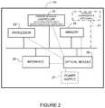
- FIG. 2illustrates an example of a network device 20 (e.g., central hub 10 , switch 14 , access point 15 in FIG. 1 ) that may be used to implement the embodiments described herein.
- the network device 20is a programmable machine that may be implemented in hardware, software, or any combination thereof.
- the network device 20includes one or more processors 22 , memory 24 , interface 26 , optical module 28 (e.g., power+optics interface module 16 in FIG. 1 ), and power module (controller) 29 .
- the network devicemay also comprise one or more cooling components 21 (sensors, control valves, pumps, etc.) if the system is configured for combined power, data, and cooling delivery.
- Memory 24may be a volatile memory or non-volatile storage, which stores various applications, operating systems, modules, and data for execution and use by the processor 22 .
- components of the optical module 28e.g., code, logic, or firmware, etc.
- the network device 20may include any number of memory components.
- the network device 20may include any number of processors 22 (e.g., single or multi-processor computing device or system), which may communicate with a forwarding engine or packet forwarder operable to process a packet or packet header.
- the processor 22may receive instructions from a software application or module, which causes the processor to perform functions of one or more embodiments described herein.
- the processor 22may also operate one or more components of the power control module 29 for fault detection, auto-negotiation, digital interlock, etc.
- the control systemmay comprise components (modules, code, software, logic) located at the central hub 10 and the remote device 14 , 15 , and interconnected through the combined power and data cable 18 ( FIGS. 1 and 2 ).
- the control systemmay also receive input from power sensors or data monitoring devices, as described below with respect to FIG. 3 .
- the power module 29may communicate with the control system at the central network device 10 to auto-negotiate the status of the power system, identify any faults in the power system (e.g., cables or powered device), and select a power operating mode. As previously noted, the auto-negotiation may be performed during a low voltage startup or between pulses in a pulse power system.
- One or more control system or power module componentsmay be located at the optical module 28 .
- Logicmay be encoded in one or more tangible media for execution by the processor 22 .
- the processor 22may execute codes stored in a computer-readable medium such as memory 24 .
- the computer-readable mediummay be, for example, electronic (e.g., RAM (random access memory), ROM (read-only memory), EPROM (erasable programmable read-only memory)), magnetic, optical (e.g., CD, DVD), electromagnetic, semiconductor technology, or any other suitable medium.
- the computer-readable mediumcomprises a non-transitory computer-readable medium.
- Logicmay be used to perform one or more functions described below with respect to the flowcharts of FIGS. 4 and 5 .
- the network device 20may include any number of processors 22 .
- the interface 26may comprise any number of network interfaces (line cards, ports, connectors) for receiving data or power, or transmitting data or power to other devices.
- the network interfacemay be configured to transmit or receive data using a variety of different communications protocols and may include mechanical, electrical, and signaling circuitry for communicating data over physical links coupled to the network interfaces.
- line cardsmay include port processors and port processor controllers.
- the interface 26may also comprise fluid ports if the system is configured for cooling.
- One or more of the interfaces 26may be configured for PoE+F+C (Power over Ethernet+Fiber+Cooling), PoE+F, PoE, PoF, or similar operation.
- the optical module 28may include logic, firmware, software, etc. for use in monitoring or controlling the advanced power over data system, as described below.
- the optical module 28may comprise hardware or software for use in power detection, power monitor and control, or power enable/disable.
- the optical module 28may further comprise one or more of the processor or memory components, or interface 26 for receiving or delivering power and data. As previously described, power is supplied to the optical module by power supply 27 and the optical module 28 provides power to the rest of the components at the network device 20 .
- network device 20 shown in FIG. 2 and described aboveis only an example and that different configurations of network devices may be used.
- the network device 20may further include any suitable combination of hardware, software, algorithms, processors, devices, components, or elements operable to facilitate the capabilities described herein.
- FIG. 3is a block diagram illustrating components for use in power monitor and control, auto-negotiation, and fault protection at a network device 30 , in accordance with one embodiment.
- One or more of the components shown in FIG. 3may be located at the interface module 16 or in communication with one or more components of the interface module ( FIGS. 1 and 3 ).
- the cable 18 carrying the high power and datais shown with cable connector 36 coupled to the interface module in FIG. 3 .
- the poweris received at an electrical interface 37 and the data is received and transmitted at an optical interface 38 .
- Connector 36may comprise a single physical component or a single component with modular parts for each function, for example.
- the network device 30includes optical/electrical components 31 for receiving optical data and converting it to electrical signals (or converting electrical signals to optical data) and power components including, power detection modules 32 a , 32 b , power monitor and control modules 33 , and power enable/disable modules 34 .
- power detection modules 32 a , 32 bpower monitor and control modules 33 , and power enable/disable modules 34 .
- the power componentsmay be isolated from the optical components 31 via an isolation component (e.g., isolation material or element), which electromagnetically isolates the power circuit from the optical components to prevent interference with operation of the optics.
- the network device 30includes an auto detection module 35 that operates with the pulse power detection module 32 a and PoE detection module 32 b .
- One or more functions of the detection elements 32 a , 32 b , auto detection module 35 , power monitor and control modules 33 , or auto-negotiation module 39may be combined into a power module and operate within the interface module.
- the auto-negotiate/digital interlock module 39may be used in performing one or more fault detection, auto-negotiation, or digital interlock processes described herein.
- auto-negotiationmay include communication between the central network device and the remote network device and interaction between controllers at the central network device and remote network device.
- One or more control signals or monitoring informationmay be transmitted over the data line (e.g., optical fibers) in the combined power and data cable 18 to provide an operating status (e.g., fault/no fault) of the network device, cable, or power circuit.
- each module 32 a , 32 bis in communication with its own power monitor and control module 33 and power enable/disable module 34 .
- the circuitdetects the type of power applied to the network device 30 , determines if PoE or pulsed power is a more efficient power delivery method, and then uses the selected power delivery mode.
- additional modesmay support other power+data standards (e.g., USB (Universal Serial Bus)).
- the network device 30is configured to calculate available power and prevent the cabling system from being energized when it should not be powered.
- the power monitor and control modules 33continuously monitor power delivery to ensure that the system can support the needed power delivery and no safety limits (e.g., voltage, current) are exceeded.
- the power monitor and control modules 33may also monitor optical signaling and disable power if there is a lack of optical transitions or communication with the power source. Power monitor and control functions may sense the voltage and current flow, and report these readings to a central control function.
- the network device 30uses a small amount of power (e.g., ⁇ 12V, ⁇ 60V) at startup or restart to communicate its power and data requirements and status.
- the network device 30may then be configured for full power operation (e.g., >60V, ⁇ 500V, ⁇ 1000V) (e.g., at high power enable/disable module 34 ) if no faults or safety conditions are detected. If a fault is detected, full power operation may not be established until the network device communicates in low power mode that high power can be safely applied.
- the auto-negotiate (fault detection module) 39may be used to test the network and components for touch-safe interrogation between pulses in a pulse power system or during a low voltage startup mode.
- the auto-negotiation module 39communicates with a control system at the central network device to select a safe operating mode (e.g., determine that it is safe to apply high voltage power), identify a fault in the circuit (e.g., line-to-line or line-to-ground fault detection), and shutdown power if a fault is identified.
- a safe operating modee.g., determine that it is safe to apply high voltage power
- identify a fault in the circuite.g., line-to-line or line-to-ground fault detection
- shutdown powerif a fault is identified.
- FIG. 4is a flowchart illustrating an overview of an auto-negotiation startup process with safety interlock, in accordance with one embodiment.
- a remote network devicee.g., switch 14 in FIG. 1
- receives combined delivery power and data from a central network devicee.g., combined power and data source 10 in FIG. 1 .
- the poweris received at an optical transceiver module 16 .
- the remote network device 14operates in a low voltage startup mode during fault sensing (detection) at the remote network device (step 42 ).
- the low voltage modemay be, for example, ⁇ 12V (volts), for example.
- the fault sensingmay be performed to check the operational status of a power circuit extending between the central network device 10 over the combined delivery cable 18 to the remote network device 14 .
- the fault sensingmay be performed using control circuits at the remote network device 14 , central network device 10 , or both network devices.
- the remote network device 14transmits a data signal to the central network device 10 over the combined delivery cable 18 indicating an operating status based on the fault sensing (step 44 ). This may include, for example, an auto-negotiation process (auto-negotiating) performed between the central network device 10 and remote network device 14 .
- the remote network deviceconverts to high power operation and a digital interlock is set between the central network device 10 and remote network device 14 (steps 46 and 48 ).
- the high power operationmay comprise, for example, power ⁇ 100V, ⁇ 500V, about 1000V (differential voltage), ⁇ 100 W, about 1000 W (load power), or any other suitable high power.
- the remote network device 14receives high voltage power from the central network device 10 on the cable 18 upon transmitting an indication of a safe operating status at the remote network device, and the network device is powered by the high voltage power.
- a pulse load currentmay be applied at the remote network device 14 and fault detection performed between pulses after the startup process is performed.
- FIG. 5illustrates an overview of a fault protection process using fault sensing between power pulses in a combined delivery power and data system, in accordance with one embodiment.
- a PSEe.g., central hub 10 in FIG. 1
- HVDChigh voltage direct current
- a powered devicee.g., remote network device 14 in FIG. 1
- a power circuit between the PSE and PDis tested between pulses (step 52 ).
- the PSEcommunicates with the PD over the cable to identify an operating mode at the PD 14 based on the testing (step 54 ).
- the PD 14operates with HVDC pulse power and the process continues with fault detection and auto-negotiation performed between pulses. If a fault is detected, power to the PD may be shut-off or the PD may switch to a low power mode. As described below, the pulse power may be HVDC load pulse power ( FIGS. 6 and 7 ), source unipolar pulse power ( FIGS. 8 and 9 ), or source bipolar (switched) power ( FIGS. 10 and 11 ).
- FIGS. 6, 8, and 10illustrate examples of circuits that may be used for fault detection with pulse power in the advanced power over data system described herein.
- FIG. 6illustrates a circuit that may be used with HVDC pulse load current with off-time auto-negotiation and shut-down for touch-safe protection.
- FIGS. 8 and 10illustrate circuits that may be used with HVDC unipolar source pulse power and HVDC bipolar source pulse power, respectively, with cable discharge pulse and open circuit off-time fault sensing and auto-negotiation.
- FIGS. 7, 9, and 11illustrate timing examples for auto-negotiation in the circuits shown in FIGS. 6, 8, and 10 , respectively.
- a low voltage startup processmay be performed to check for faults at startup before pulse power is applied and auto-negotiation is performed between pulses.
- the low voltage testing(at startup or between pulses) may include low voltage line-to-line sensing, as described below with respect to FIGS. 13 and 14 .
- a high voltage, line-to-ground testmay be performed, as described below with respect to FIG. 12 .
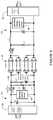
- FIG. 6illustrates a circuit for use with HVDC pulse load current with off-time auto-negotiation, in accordance with one embodiment.
- the input poweris received at an isolation stage 60 at the PSE, generally indicated at 61
- output poweris delivered at an isolation stage 62 at the PD, generally indicated at 63 .
- the PSE 61provides power to the PD 63 over a combined power and data cable, generally indicated at 65 , which in this example comprises a 4 pair cable (e.g., 100 m, 4 pair cable, or any other suitable cable configured to deliver high voltage power and data).
- a 4 pair cablee.g., 100 m, 4 pair cable, or any other suitable cable configured to deliver high voltage power and data.
- the PSE 61may provide, for example, regulated or unregulated 550 VDC with a 1 KW load and +/ ⁇ 275 VDC power (e.g., about 1042 W, 543V, 1.92 A at the PD 63 ).
- the steady state powermay be unipolar or bipolar. It is to be understood that the power, voltage, current values, and cable described herein are only provided as examples and that high voltage power may be provided at different power levels or other cable configurations may be used over different distances without departing from the scope of the embodiments.
- the PSE 61includes a sensing/control circuit 64 and the PD 63 includes a soft-start/voltage control circuit 66 .
- the soft-start/voltage control circuit 66may be used, for example, to limit the voltage applied at the powered device during startup.
- the PSE 61further comprises a PSE modulator switch Q 1 , source capacitor Cs, resistors R 1 , R 2 , R 3 and auto-negotiate current sense circuit 69 .
- the PD 63 portion of the power circuitcomprises a load capacitor C 1 , diode D 1 , inductor L 1 , and PD isolation modulator switch Q 2 .
- Switches Q 1 , Q 2may comprise, for example, a solid state switch or any other suitable device.
- PSE switch Q 1is switched on to provide continuous HVDC power unless a fault is detected during auto-negotiation of cable resistance when PD isolation switch Q 2 is switched off, as described below with respect to the timing diagram shown in FIG. 7 .
- circuit shown in FIG. 6is only an example and that other arrangements or combinations of components (e.g., resistors (R 1 , R 2 , R 3 ), capacitors (Cs, Cl), diodes (D 1 , D 2 ), inductor (L 1 ), switches (Q 1 , Q 2 ), or number of pairs in cable) may be used without departing from the scope of the embodiments.
- resistorsR 1 , R 2 , R 3
- capacitorsCs, Cl
- diodesD 1 , D 2
- inductorL 1
- switchesQ 1 , Q 2
- FIG. 7illustrates an example of a timing diagram for auto-negotiation in the circuit of FIG. 6 , in accordance with one embodiment.
- Q 1 voltageis on and continuous (as indicated at 70 ) until a fault is detected during Q 2 off-time.
- Q 2 on-time ( 72 )is 1.0 ms (millisecond).
- the resistance analysis and auto-negotiation time ( 74 )is 100 ⁇ s (microsecond). If no faults are identified during the analysis and auto-negotiation period 74 , the cycle is repeated with Q 2 on for 1.0 ms ( 72 ). In this example, the period covers 1.1 ms with a 90.9% duty cycle.
- PSE switch Q 1 in FIG. 6may be switched on for a high voltage pulse (e.g., for 1 ms) and switched off (e.g., for 100 ⁇ s) for auto-negotiation of cable resistance with PD isolation switch Q 2 off. Voltage may be measured across the capacitors Cs, Cl during testing. When the switches Q 1 , Q 2 are turned off (circuit open), the voltage across the capacitor Cl will decay as it is discharged through the resistor. If the voltage decays too quickly or too slowly, a fault may be present. Calculated line resistance may also be used and compared to a specified value to determine if there is a fault in the power circuit (cable, PSE, or PD).
- R 1 and R 2may be rated at 560 kohms each and the auto-negotiate current sense circuit 69 may comprise a 220 kohm resistor R 3 and 12V power. It should be noted that these values are only provided as examples and other resistance or voltage values may be used.
- FIG. 8shows a circuit for use with HVDC unipolar source pulse power, in accordance with one embodiment.
- the systemprovides cable discharge pulse and open circuit off-time fault sensing line-to-ground or line-to-line abnormal resistance auto-negotiate for touch-safe protection.
- the input poweris received at an isolation stage 80 of the PSE, generally indicated at 81
- poweris output from an isolation stage 82 at the PD, generally indicated at 83 .
- the source 80operates as both a low voltage source for startup (e.g., 56 VDC or other low voltage ( ⁇ 60 VDC)) and a high voltage source (e.g., 250-550 VDC) for pulsing with switch Q 1 operating as a modulator.
- a low voltage source for startupe.g., 56 VDC or other low voltage ( ⁇ 60 VDC)
- a high voltage sourcee.g., 250-550 VDC
- the PSE 81 and PD 83communicate over a combined high power and data cable, generally indicated at 85 .
- the PSE 81includes a sensing/control circuit 84 and the PD 83 includes a soft-start/voltage control circuit 86 .
- the sensing control circuit 84may include touch-safe circuits for line-to-line shock with low voltage (e.g., about 12-56V) and measures resistance at the PD as an interlock connection to enable high voltage startup and auto-negotiation between pulses with touch shock protection (e.g., 1-10 kohm) that inhibits the next high voltage pulse.
- the sensing circuit 84may also include touch-safe circuits for line-to-ground shock with high resistance midpoint ground unbalance that inhibits high voltage during pulse.
- the PSE 81comprises switches Q 1 and Q 2 , capacitor Cs, and resistors R 1 and R 2 .
- Cable discharge transistor Q 2may incorporate controlled turn-on or other means to limit peak discharge current and cable ringing.
- the PSE 81provides 1000 VDC for a 1 kW load at the PD 83 with +1.1 kV pulse power.
- the PD circuitcomprises a capacitor Cf, diode Dfw, inductor Lf, resistor R 3 (for PD connection resistor detect), and switch Q 3 .
- Switch Q 3may provide soft-start, off-time isolation, and regulation.
- resistors R 1 and R 2comprise 560 kohms resistors and R 3 is a 100 kohm resistor.
- circuit shown in FIG. 8is only an example and that other arrangements or combinations of components (e.g., resistors (R 1 , R 2 , R 3 ), capacitors (Cs, Cf), diode (Dfw), inductor (Lf), or switches (Q 1 , Q 2 , Q 3 )) may be used without departing from the scope of the embodiments. Also, different resistance or voltage values may be used.
- resistorsR 1 , R 2 , R 3
- capacitorsCs, Cf
- Dfwdiode
- Lfinductor
- switchesQ 1 , Q 2 , Q 3
- FIG. 9shows a timing diagram with a 1.0 ms-on/0.1 ms-off duty cycle for the circuit shown in FIG. 8 .
- Q 1 and Q 3 power on-time in this exampleis 1.0 ms (indicated at 90 ).
- the Q 2 cable discharge time ( 92 )is 50 ⁇ s and the resistance analysis and auto-negotiation time ( 94 ) is 50 ⁇ s. This period is repeated every 1.1 ms for a 90.9% duty cycle.
- FIG. 10illustrates a circuit for use with HVDC bipolar pulse power in accordance with one embodiment.
- the systemprovides cable discharge pulse open circuit off-time fault sensing line-to-line or line-to-ground abnormal resistance auto-negotiate for touch-safe protection,
- the circuitincludes isolation stage 100 at the PSE, generally indicated at 101 , and isolation stage 102 at the PD, generally indicated at 103 .
- the PSE 101 and PD 103are in communication over combined power and data cable, generally indicated at 105 .
- the currentmay be limited to about 1-1.2 amps to allow use of a 4-pair cable.
- the PSE 101comprises a sensing/control circuit 104 and the PD 103 includes a soft-start/voltage control circuit 106 , as previously described.
- the PSE 101comprises switches Q 1 , Q 2 , Q 3 , Q 4 that may be used to provide a low voltage startup or fault detection between pulses, as described below with respect to FIG. 11 .
- the PSE power circuitfurther includes resistors R 1 , R 2 (e.g., 560 kohm or any other suitable resistance), and an auto-negotiate current sense circuit 109 , which may provide resistance (R 3 ) (e.g., 220 kohm or other suitable resistance) and 12V (low voltage) power.
- the low voltage auto-negotiate current sense circuitfurther includes a high voltage blocking switch (Q 5 ).
- circuit shown in FIG. 10is only an example and that other arrangements or combinations of components (e.g., resistors (R 1 , R 2 , R 3 ), capacitors (C 1 , C 2 , C 3 , C 4 ), diodes (D 1 , D 2 , D 3 , D 4 ), inductors (L 1 , L 2 ), and switches (Q 1 , Q 2 , Q 3 , Q 4 , Q 5 ) may be used without departing from the scope of the embodiments.
- resistorsR 1 , R 2 , R 3
- capacitorsC 1 , C 2 , C 3 , C 4
- diodesD 1 , D 2 , D 3 , D 4
- inductorsL 1 , L 2
- switchesQ 1 , Q 2 , Q 3 , Q 4 , Q 5
- FIG. 11illustrates a timing diagram for the circuit shown in FIG. 10 , in accordance with one embodiment.
- Q 1 /Q 4 poweris on for 0.5 ms ( 110 ) and Q 3 /Q 2 power is on for 0.5 ms ( 112 ).
- Q 2 /Q 4 cable discharge time ( 114 )is 50 ⁇ s and resistance analysis and auto-negotiation time ( 116 ) is 50 ⁇ s.
- the 1.1 ms time periodis repeated for a 90.9% duty cycle.
- the timing diagrams shown in FIGS. 7, 9, and 11are only examples and that the timing or duty cycle may be different than shown without departing from the scope of the embodiments.
- the pulse power duty cyclemay be between 90% and 95%.
- FIGS. 12-13illustrate examples of touch-safe protection from line-to-ground ( FIG. 12 ) and line-to-line ( FIGS. 13 and 14 ) electrical shock.
- a midpoint grounding line-ground (GFI/GFD) shock protection sensing circuitmay be used during high voltage operation.
- Line-to-ground (GFI/GFD) fault sensingmay also be provided during low voltage operation to prevent a high voltage pulse.
- high voltage pulse poweris only allowed after auto-negotiation of safe PD connection (e.g., secure with PD resistance value of about 100 kohms) and no line-to-line body resistance fault (e.g., less than about 8 kohms at startup and for next high voltage pulse). This minimizes the chance for any contact with exposed electrical contacts.
- the short high voltage pulse time before another auto-negotiation period between high voltage pulsesmitigates the risk of high unsafe currents and electric shock danger.
- FIG. 12illustrates line-to-ground fault detection, in accordance with one embodiment.
- the PSEprovides source regulated or unregulated HVDC (e.g., 550 VDC) and the PD has load regulated HVDC (e.g., 215 VDC).
- the PSE and PDare connected over a combined delivery power and data cable, as previously described.
- the line-to-ground fault detectionmay be used with continuous power or with pulse power when the high voltage is on.
- Fast high voltage interruptionis provided with ground fault protection (shock protection) during high voltage.
- 800 k-1.4 k-8 kohms body resistance at 550 VDC for about 1 mAresults in an interrupt in ⁇ 1 ms.
- a PSE control circuit 120controls a PSE pulse modulator switch Q 1 , PSE cable discharge switch Q 2 , and GF (ground fault) comparators 124 .
- PD control circuit 122controls converter isolation switch Q 3 that has an initial low voltage startup delay before turn-on with the low voltage power, or wait for the first high voltage pulse to startup.
- the PD DC/DC converter isolation switch Q 3isolates the DC/DC converter high and low voltages from the low voltage auto-negotiation line-to-line circuit sensing the cable circuit resistance for safe PD connection and no low resistance of a body resistance fault.
- This switch circuitmay include operation as a soft-start inrush control, reverse polarity protection and also as a PWM (pulse-width modulation) voltage controller.
- the PD power circuitalso includes a PD connection resistor detect resistor R 1 .
- FIGS. 13 and 14illustrate two examples of circuits for use in line-to-line fault detection.
- High voltage touch-safe protectionis provided for line-to-line shock for pulse power applications while low voltage is on between high voltage pulses or low power mode during startup.
- auto-negotiationmay be performed using sensing of PD connection with correct resistor detection.
- Low voltage auto-negotiationmay also be performed for line-to-line fault protection (shock protection) before next high voltage pulse.
- shock protectionline-to-line fault protection
- 800 k-1.4 k-8 kohms body resistanceis assumed during low voltage test before next pulse.
- the circuits shown in FIGS. 13 and 14each include control circuits 130 , 132 at the PSE and PD, respectively. In the circuit shown in the example of FIG.
- a fault sense comparator 134 and current sense amplifier 136are used in line-to-line fault detection at the PSE.
- fault sensingis performed to identify an open cable (e.g., about 11.1V), cable to PD fault (e.g., about 6.5V), or body fault (e.g., less than about 1.8V).
- the PSE circuitincludes a PSE pulse modulator switch Q 1 and PSE cable discharge switch Q 2 .
- the PD circuitincludes PD DC/DC converter isolation switch Q 3 and resistor R 1 for use in PD connector resistor detection, as previously described.
- FIG. 15illustrates another example of a circuit for use in line-to-line fault detection, in accordance with one embodiment.
- High voltageis turned off and the PD load circuit is isolated, as previously described.
- the cable voltage capacitance discharge RC-time for resistanceis then evaluated to characterize the normal or safe cable capacitance and the circuit resistances.
- Auto-negotiationis performed during high voltage off time for line-line fault protection (shock protection) before next high voltage pulse by looking at the cable capacitance voltage RC-time droop slope to an unsafe (fault) level.
- the circuitincludes source control circuit 150 , load control circuit 152 and auto-negotiate logic 154 .
- the source control circuit 150performs fault sensing with the auto-negotiate logic 154 , PSE modulator switch Q 1 , and crowbar cable discharge switch Q 2 .
- the load control circuit 152is in communication with PD DC/DC converter isolation switch Q 3 .
- the auto-negotiate logicincludes a process for determining capacitance of the cable. In one embodiment, a safe-level off-time/RC time voltage droop level is established based on the R 5 PD detect resistance of 100 kohm, for example, with actual cable capacitance at initial startup with first high voltage pulse. Auto-negotiation is then performed for subsequent off-time RC time droop level.
- the sourceincludes resistors R 1 , R 2 , R 3 , R 4 (e.g., R 1 and R 4 at 560 kohm, and R 2 and R 3 at 10 kohm).
- the load circuitincludes inductor Lf, capacitor Cf, and PD connection resistor detect R 5 (e.g., 100 kohm).
- circuits shown in FIGS. 12, 13, 14, and 15are only examples and that other arrangements or combinations of components (e.g., resistors, capacitors, diodes, inductors, or switches) may be used without departing from the scope of the embodiments.
- additional circuits or componentsmay be included as needed.
- the PSU modulator switch Q 1is synced on/off with the Q 3 PD isolation switch on/off through data communication or with PD sensing input voltage/current to switch off and isolate the cable for auto-negotiation.
- Q 3is off, so an additional circuit may be included to get power before Q 3 to power up with a low voltage circuit.
Landscapes
- Engineering & Computer Science (AREA)
- Computer Networks & Wireless Communication (AREA)
- Signal Processing (AREA)
- Physics & Mathematics (AREA)
- Electromagnetism (AREA)
- Power Engineering (AREA)
- Remote Monitoring And Control Of Power-Distribution Networks (AREA)
- Small-Scale Networks (AREA)
Abstract
Description
Claims (35)
Priority Applications (10)
| Application Number | Priority Date | Filing Date | Title |
|---|---|---|---|
| US15/971,729US10735105B2 (en) | 2018-05-04 | 2018-05-04 | High power and data delivery in a communications network with safety and fault protection |
| PCT/US2019/028251WO2019212759A1 (en) | 2018-05-04 | 2019-04-19 | High power and data delivery in a communications network with safety and fault protection |
| CN201980030126.4ACN112075053B (en) | 2018-05-04 | 2019-04-19 | High power and data transport in a communication network with safety and fault protection |
| EP23166210.7AEP4221093B1 (en) | 2018-05-04 | 2019-04-19 | High power and data delivery in a communications network with safety and fault protection |
| JP2020561664AJP7402821B2 (en) | 2018-05-04 | 2019-04-19 | High power and data supply in communication networks with safety and fault protection |
| EP19723560.9AEP3788743B1 (en) | 2018-05-04 | 2019-04-19 | High power and data delivery in a communications network with safety and fault protection |
| EP25195514.2AEP4625893A2 (en) | 2018-05-04 | 2019-04-19 | High power and data delivery in a communications network with safety and fault protection |
| US16/913,792US11258520B2 (en) | 2018-05-04 | 2020-06-26 | High power and data delivery in a communications network with safety and fault protection |
| US17/560,446US20220116122A1 (en) | 2018-05-04 | 2021-12-23 | High power and data delivery in a communications network with safety and fault protection |
| US17/964,471US12395364B2 (en) | 2018-05-04 | 2022-10-12 | High power and data delivery in a communications network with safety and fault protection |
Applications Claiming Priority (1)
| Application Number | Priority Date | Filing Date | Title |
|---|---|---|---|
| US15/971,729US10735105B2 (en) | 2018-05-04 | 2018-05-04 | High power and data delivery in a communications network with safety and fault protection |
Related Child Applications (1)
| Application Number | Title | Priority Date | Filing Date |
|---|---|---|---|
| US16/913,792ContinuationUS11258520B2 (en) | 2018-05-04 | 2020-06-26 | High power and data delivery in a communications network with safety and fault protection |
Publications (2)
| Publication Number | Publication Date |
|---|---|
| US20190342011A1 US20190342011A1 (en) | 2019-11-07 |
| US10735105B2true US10735105B2 (en) | 2020-08-04 |
Family
ID=66484155
Family Applications (4)
| Application Number | Title | Priority Date | Filing Date |
|---|---|---|---|
| US15/971,729ActiveUS10735105B2 (en) | 2018-05-04 | 2018-05-04 | High power and data delivery in a communications network with safety and fault protection |
| US16/913,792ActiveUS11258520B2 (en) | 2018-05-04 | 2020-06-26 | High power and data delivery in a communications network with safety and fault protection |
| US17/560,446AbandonedUS20220116122A1 (en) | 2018-05-04 | 2021-12-23 | High power and data delivery in a communications network with safety and fault protection |
| US17/964,471Active2039-04-14US12395364B2 (en) | 2018-05-04 | 2022-10-12 | High power and data delivery in a communications network with safety and fault protection |
Family Applications After (3)
| Application Number | Title | Priority Date | Filing Date |
|---|---|---|---|
| US16/913,792ActiveUS11258520B2 (en) | 2018-05-04 | 2020-06-26 | High power and data delivery in a communications network with safety and fault protection |
| US17/560,446AbandonedUS20220116122A1 (en) | 2018-05-04 | 2021-12-23 | High power and data delivery in a communications network with safety and fault protection |
| US17/964,471Active2039-04-14US12395364B2 (en) | 2018-05-04 | 2022-10-12 | High power and data delivery in a communications network with safety and fault protection |
Country Status (5)
| Country | Link |
|---|---|
| US (4) | US10735105B2 (en) |
| EP (3) | EP3788743B1 (en) |
| JP (1) | JP7402821B2 (en) |
| CN (1) | CN112075053B (en) |
| WO (1) | WO2019212759A1 (en) |
Cited By (38)
| Publication number | Priority date | Publication date | Assignee | Title |
|---|---|---|---|---|
| WO2008105755A2 (en) | 2005-12-20 | 2008-09-04 | Ems Technologies, Inc. | Ferrite waveguide circulator with thermally-conductive dielectric attachments |
| US11063630B2 (en) | 2019-11-01 | 2021-07-13 | Cisco Technology, Inc. | Initialization and synchronization for pulse power in a network system |
| US11061456B2 (en) | 2019-01-23 | 2021-07-13 | Cisco Technology, Inc. | Transmission of pulse power and data over a wire pair |
| US11070393B2 (en)* | 2017-09-22 | 2021-07-20 | General Electric Technology Gmbh | Power delivery apparatus |
| US11088547B1 (en) | 2020-01-17 | 2021-08-10 | Cisco Technology, Inc. | Method and system for integration and control of power for consumer power circuits |
| US11093012B2 (en) | 2018-03-02 | 2021-08-17 | Cisco Technology, Inc. | Combined power, data, and cooling delivery in a communications network |
| US11191189B2 (en) | 2018-03-12 | 2021-11-30 | Cisco Technology, Inc. | Splitting of combined delivery power, data, and cooling in a communications network |
| US11212013B2 (en) | 2017-09-18 | 2021-12-28 | Cisco Technology, Inc. | Power delivery through an optical system |
| US11252811B2 (en) | 2020-01-15 | 2022-02-15 | Cisco Technology, Inc. | Power distribution from point-of-load with cooling |
| US20220050135A1 (en)* | 2019-05-03 | 2022-02-17 | Panduit Corp. | Method of detecting a fault in a pulsed power distribution system |
| US11258520B2 (en)* | 2018-05-04 | 2022-02-22 | Cisco Technology, Inc. | High power and data delivery in a communications network with safety and fault protection |
| US11327541B2 (en) | 2018-03-09 | 2022-05-10 | Cisco Technology, Inc. | Delivery of AC power with higher power PoE (Power over Ethernet) systems |
| US11431420B2 (en) | 2017-09-18 | 2022-08-30 | Cisco Technology, Inc. | Power delivery through an optical system |
| US11438183B2 (en) | 2020-02-25 | 2022-09-06 | Cisco Technology, Inc. | Power adapter for power supply unit |
| US11444791B2 (en) | 2019-01-23 | 2022-09-13 | Cisco Technology, Inc. | Transmission of pulse power and data in a communications network |
| US11456883B2 (en) | 2019-03-13 | 2022-09-27 | Cisco Technology, Inc. | Multiple phase pulse power in a network communications system |
| US11482351B2 (en) | 2020-09-29 | 2022-10-25 | Hewlett Packard Enterprise Development Lp | Pluggable network interface port with powering for remote device |
| US11519789B2 (en) | 2017-05-24 | 2022-12-06 | Cisco Technology, Inc. | Thermal modeling for cables transmitting data and power |
| US11543844B2 (en) | 2020-02-25 | 2023-01-03 | Cisco Technology, Inc. | Method and apparatus for transmitting power and data in a multi-drop architecture |
| US11582048B2 (en) | 2020-07-17 | 2023-02-14 | Cisco Technology, Inc. | Bi-directional power over ethernet for digital building applications |
| US11637497B2 (en) | 2020-02-28 | 2023-04-25 | Cisco Technology, Inc. | Multi-phase pulse power short reach distribution |
| US11683190B2 (en) | 2018-04-05 | 2023-06-20 | Cisco Technology, Inc. | Wire fault and electrical imbalance detection for power over communications cabling |
| US11708002B2 (en) | 2020-08-03 | 2023-07-25 | Cisco Technology, Inc. | Power distribution and communications for electric vehicle |
| US11714118B2 (en) | 2017-05-24 | 2023-08-01 | Cisco Technology, Inc. | Safety monitoring for cables transmitting data and power |
| US11745613B2 (en) | 2020-08-26 | 2023-09-05 | Cisco Technology, Inc. | System and method for electric vehicle charging and security |
| US11797350B2 (en) | 2020-02-25 | 2023-10-24 | Cisco Technology, Inc. | Method and apparatus for providing data center functions for support of an electric vehicle based data center |
| US11831109B2 (en) | 2020-12-15 | 2023-11-28 | Cisco Technology, Inc. | Electrical connector with integrated electronic controlled power switch or circuit breaker safety device |
| US11853138B2 (en) | 2020-01-17 | 2023-12-26 | Cisco Technology, Inc. | Modular power controller |
| US20240048944A1 (en)* | 2019-05-29 | 2024-02-08 | Texas Instruments Incorporated | Integrated wi-fi location |
| US11916374B2 (en) | 2021-08-05 | 2024-02-27 | Cisco Technology, Inc. | Fault managed power system |
| US12107047B2 (en) | 2021-01-11 | 2024-10-01 | Cisco Technology, Inc. | Apparatus and method for direct power delivery to integrated circuit package |
| US12113362B2 (en) | 2022-03-18 | 2024-10-08 | Equinox Power Innovations Inc. | Fault-responsive power system and method using active line current balancing |
| US12126399B2 (en) | 2019-11-01 | 2024-10-22 | Cisco Technology, Inc. | Fault managed power with dynamic and adaptive fault sensor |
| US12160133B2 (en) | 2020-06-30 | 2024-12-03 | Cisco Technology, Inc. | Method and apparatus for efficient power delivery in power supply system |
| US12348225B2 (en) | 2022-05-23 | 2025-07-01 | Panduit Corp. | Systems, apparatuses, and methods for pulse shaping in high voltage power systems |
| US12374988B2 (en) | 2022-03-18 | 2025-07-29 | Equinox Power Innovations Inc. | Fault-responsive power system and method using asynchronous load current switching |
| WO2025183992A2 (en) | 2024-02-28 | 2025-09-04 | Voltserver Inc. | Digital electricity controller |
| US12443259B2 (en) | 2022-11-23 | 2025-10-14 | Cisco Technology, Inc. | Remote switch synchronization for pulse power and fault managed power (FMP) applications |
Families Citing this family (27)
| Publication number | Priority date | Publication date | Assignee | Title |
|---|---|---|---|---|
| US10281513B1 (en) | 2018-03-09 | 2019-05-07 | Cisco Technology, Inc. | Verification of cable application and reduced load cable removal in power over communications systems |
| US10770203B2 (en) | 2018-07-19 | 2020-09-08 | Commscope Technologies Llc | Plug-in power and data connectivity micro grids for information and communication technology infrastructure and related methods of deploying such micro grids |
| US10680836B1 (en) | 2019-02-25 | 2020-06-09 | Cisco Technology, Inc. | Virtualized chassis with power-over-Ethernet for networking applications |
| TWI687020B (en)* | 2019-03-14 | 2020-03-01 | 永滐投資有限公司 | Network and Power Sharing Device |
| JP7239421B2 (en)* | 2019-08-02 | 2023-03-14 | 京セラ株式会社 | Optical fiber power supply system and power supply side data communication device for optical fiber power supply system |
| US12335138B2 (en) | 2019-11-27 | 2025-06-17 | Rockwell Collins, Inc. | Spatial awareness navigation techniques on unmanned aerial vehicles (spatial awareness) |
| US12050279B2 (en) | 2019-11-27 | 2024-07-30 | Rockwell Collins, Inc. | Doppler nulling spatial awareness (DNSA) solutions for non-terrestrial networks |
| US12137048B2 (en) | 2019-11-27 | 2024-11-05 | Rockwell Collins, Inc. | System and method for spatial awareness network routing |
| US12326506B2 (en) | 2019-11-27 | 2025-06-10 | Rockwell Collins, Inc. | DNS spatial discoveries with on-going traffic |
| US12153150B2 (en) | 2019-11-27 | 2024-11-26 | Rockwell Collins, Inc. | Doppler nulling scanning (DNS) security (spatial awareness) |
| US12366625B2 (en) | 2019-11-27 | 2025-07-22 | Rockwell Collins, Inc. | System and method using passive spatial awareness for GEO network routing |
| US12316403B2 (en) | 2022-05-20 | 2025-05-27 | Rockwell Collins, Inc. | Situational awareness (SA) in radio silence (spatial awareness) |
| US11665658B1 (en) | 2021-04-16 | 2023-05-30 | Rockwell Collins, Inc. | System and method for application of doppler corrections for time synchronized transmitter and receiver |
| US12407393B2 (en) | 2019-11-27 | 2025-09-02 | Rockwell Collins, Inc. | System and method for spatial awareness overlay onto mobile ad hoc network (MANET) frequent message preambles |
| US11307368B2 (en) | 2020-04-07 | 2022-04-19 | Cisco Technology, Inc. | Integration of power and optics through cold plates for delivery to electronic and photonic integrated circuits |
| US11320610B2 (en) | 2020-04-07 | 2022-05-03 | Cisco Technology, Inc. | Integration of power and optics through cold plate for delivery to electronic and photonic integrated circuits |
| US11915276B2 (en) | 2020-04-28 | 2024-02-27 | Cisco Technology, Inc. | System, method, and computer readable storage media for millimeter wave radar detection of physical actions coupled with an access point off-load control center |
| CN115702532A (en)* | 2020-10-13 | 2023-02-14 | 施耐德电气美国股份有限公司 | Fault management power system |
| CN113194586B (en)* | 2021-04-23 | 2023-04-25 | 勤上光电股份有限公司 | Lighting control method and lighting system based on edge computing gateway |
| CN113376559B (en)* | 2021-04-25 | 2022-08-26 | 国网安徽省电力有限公司营销服务中心 | Digital metering system abnormal field rapid diagnosis method and diagnosis system thereof |
| DE102021120393B3 (en) | 2021-08-05 | 2022-09-08 | Turck Holding Gmbh | Method and interconnection for operating a network or network section |
| US11979751B2 (en)* | 2021-09-16 | 2024-05-07 | Cisco Technology, Inc. | Selection of standard power mode candidate access points with 6 GHz radios |
| WO2023244794A1 (en)* | 2022-06-16 | 2023-12-21 | Schneider Electric USA, Inc. | Pulse width modulated fault managed power systems |
| US20240069296A1 (en)* | 2022-08-25 | 2024-02-29 | Broadcom International Pte. Ltd. | Electrical and optical connector |
| US20250096908A1 (en)* | 2023-09-15 | 2025-03-20 | Panduit Corp. | Fault managed power over optical network channels |
| EP4525243A3 (en)* | 2023-09-15 | 2025-05-07 | Panduit Corp. | Fault managed power including optical communication elements |
| CN118890228A (en)* | 2024-07-08 | 2024-11-01 | 厦门和储能源科技有限公司 | A star-shaped battery management system network topology based on POE power supply |
Citations (129)
| Publication number | Priority date | Publication date | Assignee | Title |
|---|---|---|---|---|
| US3335324A (en)* | 1965-10-06 | 1967-08-08 | Westinghouse Air Brake Co | Fail-safe continuous ground monitoring circuit |
| US4811187A (en) | 1985-02-12 | 1989-03-07 | Hitachi Metals Ltd. | DC-DC converter with saturable reactor reset circuit |
| WO1993016407A1 (en) | 1992-02-18 | 1993-08-19 | Angelase, Inc. | Cooled multi-fiber medical connector |
| US6220955B1 (en) | 1998-02-17 | 2001-04-24 | John G. Posa | Combination power and cooling cable |
| US6259745B1 (en) | 1998-10-30 | 2001-07-10 | Broadcom Corporation | Integrated Gigabit Ethernet transmitter architecture |
| US20020126967A1 (en) | 1996-03-29 | 2002-09-12 | Dominion Lasercom, Inc. | Hybrid electro-optic cable |
| US20040000816A1 (en) | 2002-06-26 | 2004-01-01 | Bahman Khoshnood | Apparatus and method for distributing data and controlled temperature air to electronic equipment via electronic device power cord plug assemblies with mating wall outlets which incorporate integral signal and/or controlled temperature air supply lines |
| US6685364B1 (en) | 2001-12-05 | 2004-02-03 | International Business Machines Corporation | Enhanced folded flexible cable packaging for use in optical transceivers |
| US20040033076A1 (en) | 2002-08-06 | 2004-02-19 | Jae-Won Song | Wavelength division multiplexing passive optical network system |
| US20040043651A1 (en)* | 2002-08-29 | 2004-03-04 | Dell Products L.P. | AC adapter connector assembly |
| US20040073703A1 (en)* | 1997-10-14 | 2004-04-15 | Alacritech, Inc. | Fast-path apparatus for receiving data corresponding a TCP connection |
| US6826368B1 (en) | 1998-10-20 | 2004-11-30 | Lucent Technologies Inc. | Wavelength division multiplexing (WDM) with multi-frequency lasers and optical couplers |
| CN1209880C (en) | 2001-11-30 | 2005-07-06 | 王德清 | Wideband access transmission entwork as assembly of power supply, telecommunication device, TV set and internet network |
| US20050197018A1 (en) | 2004-03-02 | 2005-09-08 | Charles Lord | Keyed universal power tip and power source connectors |
| US20050268120A1 (en) | 2004-05-13 | 2005-12-01 | Schindler Frederick R | Power delivery over ethernet cables |
| US20060202109A1 (en)* | 2005-03-14 | 2006-09-14 | The Boeing Company | Method and apparatus for optically powering and multiplexing distributed fiber optic sensors |
| US20070103168A1 (en)* | 2005-11-09 | 2007-05-10 | Batten Douglas W | Loop impedance meter |
| US20070288125A1 (en) | 2006-06-09 | 2007-12-13 | Mks Instruments, Inc. | Power Over Ethernet (Poe) - Based Measurement System |
| US7325150B2 (en) | 1999-01-12 | 2008-01-29 | Microsemi Corp.—Analog Mixed Signal Group, Ltd. | Combiner for power delivery over data communication cabling infrastructure |
| EP1936861A1 (en) | 2006-12-19 | 2008-06-25 | Broadcom Corporation | System and method for controlling power delivered to a powered device based on cable characteristics |
| US20080198635A1 (en) | 2007-02-21 | 2008-08-21 | Broadcom Corporation | Pulse width modulated ground/return for powered device |
| US7420355B2 (en) | 2006-07-11 | 2008-09-02 | Artesyn Technologies, Inc. | DC-DC converter with over-voltage protection |
| US20080229120A1 (en) | 2007-03-12 | 2008-09-18 | Broadcom Corporation | System and method for continual cable thermal monitoring using cable resistance considerations in power over ethernet |
| US20080310067A1 (en) | 2007-06-12 | 2008-12-18 | Broadcom Corporation | System and method for using a phy to locate a thermal signature in a cable plant for diagnostic, enhanced, and higher power applications |
| US7583703B2 (en) | 2003-10-23 | 2009-09-01 | Cisco Technology Inc. | System and method for power injection and out of band communications on shared medium |
| US7589435B2 (en) | 2006-08-02 | 2009-09-15 | Cisco Technology, Inc. | Reporting power requirements of a powered device |
| US7593747B1 (en) | 2005-07-01 | 2009-09-22 | Cisco Technology, Inc. | Techniques for controlling delivery of power to a remotely powerable device based on temperature |
| US7616465B1 (en) | 2004-02-24 | 2009-11-10 | Vlt, Inc. | Energy storage and hold-up method and apparatus for high density power conversion |
| EP2120443A1 (en) | 2008-05-15 | 2009-11-18 | BRITISH TELECOMMUNICATIONS public limited company | Power supply system |
| US20100117808A1 (en)* | 2008-11-11 | 2010-05-13 | Cisco Technology Inc. | Powered communications interface providing low-speed communications between power-sourcing equipment and powered device in non-powered operating mode |
| WO2010053542A2 (en) | 2008-11-08 | 2010-05-14 | Sensortran, Inc. | System and method for determining characteristics of power cables using distributed temperature sensing systems |
| US20100171602A1 (en) | 2009-01-05 | 2010-07-08 | Hazem Kabbara | Intelligent Power Management of an Intermediate Network Device Switching Circuitry and PoE Delivery |
| US20100190384A1 (en) | 2004-11-12 | 2010-07-29 | Comarco Wireless Technologies, Inc. | Key coded power adapter connectors |
| US7813646B2 (en) | 2007-07-11 | 2010-10-12 | RLH Industries, Inc | Power over optical fiber system |
| US7835389B2 (en) | 2006-09-20 | 2010-11-16 | Broadcom Corporation | Method and system for an extended range Ethernet line code using 4B/3B mapping |
| US20100290190A1 (en) | 2009-05-12 | 2010-11-18 | Iceotope Limited | Cooled electronic system |
| CN201689347U (en) | 2010-05-06 | 2010-12-29 | 谭志明 | POE (Power Over Ethernet) power supply temperature control device |
| US7915761B1 (en) | 2006-09-27 | 2011-03-29 | Cisco Technology, Inc. | Power injector detection |
| US7921307B2 (en) | 2007-03-27 | 2011-04-05 | Cisco Technology, Inc. | Methods and apparatus providing advanced classification for power over Ethernet |
| US7924579B2 (en) | 2008-02-05 | 2011-04-12 | Cisco Technology, Inc. | Fly-forward converter power supply |
| US20110083824A1 (en) | 2009-06-03 | 2011-04-14 | Bripco Bvba | Data Centre |
| US7940787B2 (en) | 2005-08-30 | 2011-05-10 | Cisco Technology, Inc. | Low-power ethernet device |
| US7973538B2 (en) | 2008-08-21 | 2011-07-05 | Cisco Technology, Inc. | Power over ethernet system having hazard detection circuitry to detect potentially hazardous cable conditions |
| US8020043B2 (en) | 2009-03-06 | 2011-09-13 | Cisco Technology, Inc. | Field failure data collection |
| US8037324B2 (en) | 2007-03-20 | 2011-10-11 | Broadcom Corporation | Power over ethernet connector with integrated power source equipment (PSE) controller supporting high power applications |
| US20110266867A1 (en) | 2010-05-03 | 2011-11-03 | Cisco Technology Inc. | Power-sharing network communications device |
| US20110290497A1 (en) | 2010-05-28 | 2011-12-01 | Karl-Atle Stenevik | Subsea hydrocarbon production system |
| US20120064745A1 (en) | 2007-06-05 | 2012-03-15 | Martin Ottliczky | Hybrid universal distribution system comprising electrical, fluid, and communication functions |
| US8184525B2 (en) | 2005-05-25 | 2012-05-22 | Cisco Technology, Inc. | Method and apparatus for detecting and fixing faults in an inline-power capable ethernet system |
| US20120170927A1 (en) | 2010-12-30 | 2012-07-05 | Yuanjun Huang | Circuits, Architectures, Apparatuses, Systems, and Methods for Merging of Management and Data Signals, and for Recovery of a Management Signal |
| US20120201089A1 (en) | 1995-10-19 | 2012-08-09 | Rambus Inc. | Integrated circuit device comprises an interface to transmit a first code, a strobe signal after a delay and data to a dynamic random access memory (dram) |
| US20120231654A1 (en) | 2009-11-06 | 2012-09-13 | G.B.D. Corp. | Electrical cord and apparatus using same |
| US8276397B1 (en) | 2007-06-27 | 2012-10-02 | Exaflop Llc | Cooling and power paths for data center |
| US20120317426A1 (en) | 2011-06-09 | 2012-12-13 | Andrew Llc | Distributed antenna system using power-over-ethernet |
| US20120319468A1 (en) | 2010-03-19 | 2012-12-20 | Videolarm, Inc. | Power over ethernet prioritization system and method for surveillance cameras |
| US8345439B1 (en) | 2008-11-18 | 2013-01-01 | Force10 Networks, Inc. | Modular chassis arrangement with redundant logic power delivery system |
| US8350538B2 (en) | 2009-04-11 | 2013-01-08 | Cuks, Llc | Voltage step-down switching DC-to-DC converter |
| US8358893B1 (en)* | 2010-01-14 | 2013-01-22 | Sandia Corporation | Photonic-powered cable assembly |
| US20130077923A1 (en) | 2011-09-23 | 2013-03-28 | Tyco Electronics Corporation | Hybrid Cable Assembly |
| US20130079633A1 (en) | 2011-09-23 | 2013-03-28 | Tyco Electronics Corporation | Diagnostic System with Hybrid Cable Assembly |
| US20130103220A1 (en) | 2009-10-27 | 2013-04-25 | Voltserver Inc. | Safe Exposed Conductor Power Distribution System |
| US20130249292A1 (en)* | 2010-11-24 | 2013-09-26 | Corning Cable Systems Llc | Power distribution module(s) capable of hot connection and/or disconnection for distributed antenna systems, and related power units, components, and methods |
| US20130272721A1 (en) | 2012-04-13 | 2013-10-17 | Alcatel-Lucent Usa, Inc. | Optical network device employing three-level duobinary modulation and method of use thereof |
| EP2693688A1 (en) | 2012-08-03 | 2014-02-05 | Broadcom Corporation | Cable imbalance diagnostics between channels that include wire pairs for power over ethernet transmission |
| US8700923B2 (en) | 2000-09-27 | 2014-04-15 | Huron Ip Llc | Apparatus and method for modular dynamically power managed power supply and cooling system for computer systems, server applications, and other electronic devices |
| US8829917B1 (en) | 2002-06-07 | 2014-09-09 | Marvell International Ltd. | Cable tester |
| US20140258742A1 (en) | 2013-03-05 | 2014-09-11 | Ching-Yun CHIEN | Hybrid fiber optic and power over ethernet |
| US8836228B2 (en) | 2011-05-11 | 2014-09-16 | Fsp Technology Inc. | Non-isolated resonant converter |
| US8842430B2 (en) | 2008-12-31 | 2014-09-23 | Cirrascale Corporation | Data center |
| CN104081237A (en) | 2011-10-26 | 2014-10-01 | 康宁光电通信有限责任公司 | Composite cable breakout assembly |
| US20150078740A1 (en) | 2013-09-19 | 2015-03-19 | RADIUS UNIVERSAL, A Limited Liability Company of the State of New York | Fiber optic communications network |
| US20150106539A1 (en) | 2013-10-10 | 2015-04-16 | Nokia Corporation | Communication control pins in a dual row connector |
| US20150115741A1 (en)* | 2013-10-29 | 2015-04-30 | Avaya Inc. | Ac power over ethernet |
| US9024473B2 (en) | 2011-08-30 | 2015-05-05 | Linear Technology Corporation | Power combining in power over ethernet systems |
| US20150215001A1 (en) | 2014-01-26 | 2015-07-30 | VoltServer, Inc. | Packet Energy Transfer In-Line Communications |
| US9189043B2 (en) | 2006-01-17 | 2015-11-17 | Broadcom Corporation | Apparatus and method for multipoint detection in power-over-ethernet detection mode |
| US20150333918A1 (en) | 2014-05-15 | 2015-11-19 | Schneider Electric Buildings, Llc | Power over ethernet enabled sensor and sensor network |
| US20160020911A1 (en)* | 2013-09-19 | 2016-01-21 | RADIUS UNIVERSAL, A Limited Liability Company of the State of New York | Fiber optic communications and power network |
| US9273906B2 (en) | 2012-06-14 | 2016-03-01 | International Business Machines Corporation | Modular pumping unit(s) facilitating cooling of electronic system(s) |
| US20160064938A1 (en) | 2014-08-26 | 2016-03-03 | Cisco Technology, Inc. | Dynamically Configurable Power-Over-Ethernet Apparatus and Method |
| US9319101B2 (en) | 2012-09-28 | 2016-04-19 | Siemens Industry, Inc. | System and method for ground fault detection in a transformer isolated communication channel of a network device |
| US20160111877A1 (en) | 2014-10-21 | 2016-04-21 | VoltServer, Inc. | Digital Power Receiver System |
| US20160134331A1 (en) | 2014-11-07 | 2016-05-12 | VoltServer, Inc. | Packet Energy Transfer Power Control Elements |
| US20160142217A1 (en) | 2014-11-19 | 2016-05-19 | Linear Technology Corporation | DETECTING GROUND ISOLATION FAULT IN ETHERNET PoDL SYSTEM |
| US9373963B2 (en) | 2013-05-24 | 2016-06-21 | Raytheon Company | Energy transfer and storage apparatus for delivery of pulsed power |
| US20160197600A1 (en) | 2015-01-07 | 2016-07-07 | Raytheon Company | Method and apparatus for control of pulsed power in hybrid energy storage module |
| US20160241148A1 (en) | 2015-02-13 | 2016-08-18 | Avogy, Inc. | Method and system for integrated power supply with accessory functions |
| CN205544597U (en) | 2016-03-18 | 2016-08-31 | 江苏联宏自动化系统工程有限公司 | Multi -functional three -phase power monitoring device |
| US20160262288A1 (en) | 2015-03-03 | 2016-09-08 | International Business Machines Corporation | Active control for two-phase cooling |
| US20160294500A1 (en)* | 2015-04-03 | 2016-10-06 | John Mezzalingua Associates, LLC | Packet energy transfer powered telecommunications system for macro antenna systems and power distribution system therefor |
| US20160308683A1 (en) | 2015-04-14 | 2016-10-20 | Broadcom Corporation | Power coupling circuits for single-pair ethernet with automotive applications |
| US9510479B2 (en) | 2011-05-27 | 2016-11-29 | Lockheed Martin Corporation | Fluid-cooled module for integrated circuit devices |
| US20160352535A1 (en) | 2014-01-29 | 2016-12-01 | Hewlett Packard Enterprise Development Lp | Managing a number of ethernet links |
| US20160365967A1 (en) | 2015-06-11 | 2016-12-15 | Broadcom Corporation | Link establishment for single pair ethernet |
| US20170054296A1 (en) | 2008-09-13 | 2017-02-23 | Moixa Energy Holdings Limited | Systems, devices and methods for electricity provision, usage monitoring, analysis, and enabling improvements in efficiency |
| US9590811B2 (en) | 2010-04-02 | 2017-03-07 | Commscope Technologies Llc | Method and apparatus for distributing power over communication cabling |
| WO2017054030A1 (en) | 2015-09-29 | 2017-04-06 | Electrical Engineering Solutions Pty Ltd | A mobile power, data and lighting system |
| US20170110871A1 (en) | 2015-10-16 | 2017-04-20 | Frederick M. Foster | Circuit protection system and method |
| US20170146260A1 (en) | 2015-11-25 | 2017-05-25 | Johnson Controls Technology Company | Modular multi-function thermostat |
| US9665148B2 (en) | 2012-11-07 | 2017-05-30 | Dell Products L.P. | PoE power distribution system for PoE-powered port extender having multiple data and power inputs |
| US20170155517A1 (en)* | 2015-11-30 | 2017-06-01 | Huawei Technologies Co., Ltd. | Power over Ethernet Method and Device |
| US20170155518A1 (en) | 2015-11-30 | 2017-06-01 | Huawei Technologies Co., Ltd. | POE-Based Power Supply Method and PSE |
| US20170164525A1 (en) | 2007-03-14 | 2017-06-08 | Zonit Structured Solutions, Llc | Air-based cooling for data center rack |
| US9693244B2 (en) | 2011-05-25 | 2017-06-27 | Nec Corporation | Sensor and receiving device in sensor system |
| US20170214236A1 (en) | 2016-01-24 | 2017-07-27 | VoltServer, Inc. | Method and Apparatus for Parallel Operation of Packet Energy Transfer Receivers |
| US20170229886A1 (en) | 2016-02-08 | 2017-08-10 | VoltServer, Inc. | Digital Electricity Transmission System using Reversal Sensing Packet Energy Transfer |
| US9734940B1 (en) | 2016-04-14 | 2017-08-15 | Superior Essex International LP | Communication cables incorporating twisted pair components |
| US20170234738A1 (en) | 2014-05-21 | 2017-08-17 | Amazon Technologies, Inc. | Virtual data center environmental monitoring system |
| US20170248976A1 (en) | 2016-02-26 | 2017-08-31 | Nel Hydrogen A/S | Communication system for a hydrogen refuelling system |
| WO2017167926A1 (en) | 2016-04-01 | 2017-10-05 | Canon Kabushiki Kaisha | Power management method of a system made of devices powered over data cable |
| US20170325320A1 (en) | 2014-10-28 | 2017-11-09 | Philips Lighting Holding B.V. | Apparatus, method and system for controlling a load device via a power line by using a power negotiatiion protocol |
| US9874930B2 (en) | 2015-09-03 | 2018-01-23 | Cisco Technology, Inc. | Selection of power in power over ethernet systems |
| WO2018017544A1 (en) | 2016-07-18 | 2018-01-25 | Commscope Technologies Llc | Systems and methods for high capacity power delivery to remote nodes |
| US20180024964A1 (en) | 2016-07-19 | 2018-01-25 | Pure Storage, Inc. | Disaggregated compute resources and storage resources in a storage system |
| US9893521B2 (en) | 2014-01-19 | 2018-02-13 | VoltServer, Inc. | Digital power network method and apparatus |
| US20180060269A1 (en) | 2016-08-25 | 2018-03-01 | Analog Devices, Inc. | Systems and techniques for remote bus enable |
| US20180088648A1 (en) | 2016-09-27 | 2018-03-29 | Renesas Electronics Corporation | Power feeding system and negotiation controller |
| US20180098201A1 (en)* | 2016-02-08 | 2018-04-05 | Cree, Inc. | Indoor location services using a distributed lighting network |
| US20180102604A1 (en) | 2013-09-26 | 2018-04-12 | Commscope, Inc. Of North Carolina | Patch cords for reduced-pair ethernet applications having strain relief units that resist rotational loads and related strain relief units and connectors |
| US9948198B2 (en) | 2015-05-12 | 2018-04-17 | Tdk Corporation | Resonant converter and switching power supply device |
| US20180123360A1 (en) | 2016-10-31 | 2018-05-03 | VoltServer, Inc. | Digital Power Multiport Battery Charging System |
| US10007628B2 (en) | 2014-06-18 | 2018-06-26 | Qualcomm Incorporated | Dynamically adjustable multi-line bus shared by multi-protocol devices |
| US20180191513A1 (en) | 2016-12-29 | 2018-07-05 | Nexans | Active Cooling Arrangement For Power Over Ethernet Arrangements |
| US20180188712A1 (en)* | 2016-07-22 | 2018-07-05 | Michael T. MacKay | Relevance based digital building |
| US10028417B2 (en) | 2016-05-11 | 2018-07-17 | Facebook, Inc. | Modular network switches, associated structures, and associated methods of manufacture and use |
| US20180254624A1 (en)* | 2017-03-06 | 2018-09-06 | Lsis Co., Ltd. | Apparatus for detecting fault of power relay of inverter |
| US20180313886A1 (en) | 2017-04-26 | 2018-11-01 | VoltServer, Inc. | Methods for Verifying Digital-Electricity Line Integrity |
| WO2019023731A1 (en) | 2017-08-04 | 2019-02-07 | Electrical Engineering Solutions Pty Limited | A poe system for the distribution of high voltage power, data and lighting and a common mode signalling system incorporated therein |
| US10407995B2 (en) | 2012-07-05 | 2019-09-10 | Sdg Llc | Repetitive pulsed electric discharge drills including downhole formation evaluation |
Family Cites Families (26)
| Publication number | Priority date | Publication date | Assignee | Title |
|---|---|---|---|---|
| WO2002013406A1 (en) | 2000-08-04 | 2002-02-14 | Exscoms Ltd. | Communication system and communication method using power lines |
| CN100391151C (en)* | 2006-05-26 | 2008-05-28 | 广东天波信息技术有限公司 | Intelligent low voltage detection far-distance power supply system |
| US7566987B2 (en) | 2006-09-14 | 2009-07-28 | Lutron Electronics Co., Inc. | Method of powering up a plurality of loads in sequence |
| US8068937B2 (en) | 2008-02-09 | 2011-11-29 | Stephen Spencer Eaves | Power distribution system with fault protection using energy packet confirmation |
| US8245056B2 (en)* | 2008-07-24 | 2012-08-14 | Broadcom Corporation | Unified bus architecture for PoE communication and control |
| US8638008B2 (en)* | 2009-12-22 | 2014-01-28 | Direct Power Tech Ip, Llc | 380 volt direct current power distribution system for information and communication technology systems and facilities |
| CN102123034B (en)* | 2011-02-28 | 2015-08-26 | 中兴通讯股份有限公司 | POE system is utilized to carry out method and the device of high-low pressure selection power supply |
| JP5002714B1 (en)* | 2011-03-29 | 2012-08-15 | 株式会社東芝 | COMMUNICATION DEVICE, COMMUNICATION DEVICE POWER CONTROL METHOD, AND PROGRAM |
| US8768528B2 (en) | 2011-05-16 | 2014-07-01 | Vcharge, Inc. | Electrical thermal storage with edge-of-network tailored energy delivery systems and methods |
| US9859951B2 (en)* | 2013-11-26 | 2018-01-02 | Linear Technology Corporation | Power over data lines detection and classification scheme |
| US9780955B2 (en) | 2014-06-19 | 2017-10-03 | Microsemi P.O.E Ltd. | Power over ethernet method and apparatus for immediate power availability |
| CN204069002U (en)* | 2014-09-12 | 2014-12-31 | 绵阳灵通电讯设备有限公司 | Based on number, the electric simultaneous interpretation device of insulate line remote auto power supply technique |
| US20160294568A1 (en) | 2015-04-03 | 2016-10-06 | John Mezzalingua Associates, LLC | Packet energy transfer powered telecommunications system for distributed antenna systems and integrated wireless fidelity system |
| WO2017062368A1 (en) | 2015-10-09 | 2017-04-13 | 3M Innovative Properties Company | Accessory mounting device and system using same |
| US10263526B2 (en) | 2016-08-02 | 2019-04-16 | Smart Prong Technologies, Inc. | Electrical circuit for isolated voltage conversion |
| EP3327732B1 (en)* | 2016-11-23 | 2019-05-01 | Hexatronic Group AB | Hybrid cable and associated communication system |
| EP3602733B1 (en) | 2017-03-31 | 2024-01-03 | Corning Optical Communications Llc | Safety power disconnection for power distribution over power conductors to power consuming devices |
| US20200295559A1 (en) | 2017-10-15 | 2020-09-17 | VoltServer, Inc. | Digital Power Distribution System with a Non-Linear Load |
| US10714930B1 (en) | 2018-03-09 | 2020-07-14 | VoltServer, Inc. | Digital electricity using carrier wave change detection |
| US10735105B2 (en)* | 2018-05-04 | 2020-08-04 | Cisco Technology, Inc. | High power and data delivery in a communications network with safety and fault protection |
| US10790997B2 (en) | 2019-01-23 | 2020-09-29 | Cisco Technology, Inc. | Transmission of pulse power and data in a communications network |
| US11061456B2 (en) | 2019-01-23 | 2021-07-13 | Cisco Technology, Inc. | Transmission of pulse power and data over a wire pair |
| US11456883B2 (en) | 2019-03-13 | 2022-09-27 | Cisco Technology, Inc. | Multiple phase pulse power in a network communications system |
| EP3963826B1 (en) | 2019-05-03 | 2023-12-20 | Panduit Corp. | Method of detecting a fault in a pulsed power distribution system |
| US11063630B2 (en) | 2019-11-01 | 2021-07-13 | Cisco Technology, Inc. | Initialization and synchronization for pulse power in a network system |
| CN115702532A (en) | 2020-10-13 | 2023-02-14 | 施耐德电气美国股份有限公司 | Fault management power system |
- 2018
- 2018-05-04USUS15/971,729patent/US10735105B2/enactiveActive
- 2019
- 2019-04-19WOPCT/US2019/028251patent/WO2019212759A1/ennot_activeCeased
- 2019-04-19EPEP19723560.9Apatent/EP3788743B1/enactiveActive
- 2019-04-19EPEP23166210.7Apatent/EP4221093B1/enactiveActive
- 2019-04-19JPJP2020561664Apatent/JP7402821B2/enactiveActive
- 2019-04-19CNCN201980030126.4Apatent/CN112075053B/enactiveActive
- 2019-04-19EPEP25195514.2Apatent/EP4625893A2/enactivePending
- 2020
- 2020-06-26USUS16/913,792patent/US11258520B2/enactiveActive
- 2021
- 2021-12-23USUS17/560,446patent/US20220116122A1/ennot_activeAbandoned
- 2022
- 2022-10-12USUS17/964,471patent/US12395364B2/enactiveActive
Patent Citations (142)
| Publication number | Priority date | Publication date | Assignee | Title |
|---|---|---|---|---|
| US3335324A (en)* | 1965-10-06 | 1967-08-08 | Westinghouse Air Brake Co | Fail-safe continuous ground monitoring circuit |
| US4811187A (en) | 1985-02-12 | 1989-03-07 | Hitachi Metals Ltd. | DC-DC converter with saturable reactor reset circuit |
| WO1993016407A1 (en) | 1992-02-18 | 1993-08-19 | Angelase, Inc. | Cooled multi-fiber medical connector |
| US20120201089A1 (en) | 1995-10-19 | 2012-08-09 | Rambus Inc. | Integrated circuit device comprises an interface to transmit a first code, a strobe signal after a delay and data to a dynamic random access memory (dram) |
| US20020126967A1 (en) | 1996-03-29 | 2002-09-12 | Dominion Lasercom, Inc. | Hybrid electro-optic cable |
| US20040073703A1 (en)* | 1997-10-14 | 2004-04-15 | Alacritech, Inc. | Fast-path apparatus for receiving data corresponding a TCP connection |
| US6220955B1 (en) | 1998-02-17 | 2001-04-24 | John G. Posa | Combination power and cooling cable |
| US6826368B1 (en) | 1998-10-20 | 2004-11-30 | Lucent Technologies Inc. | Wavelength division multiplexing (WDM) with multi-frequency lasers and optical couplers |
| US6259745B1 (en) | 1998-10-30 | 2001-07-10 | Broadcom Corporation | Integrated Gigabit Ethernet transmitter architecture |
| US7325150B2 (en) | 1999-01-12 | 2008-01-29 | Microsemi Corp.—Analog Mixed Signal Group, Ltd. | Combiner for power delivery over data communication cabling infrastructure |
| US8700923B2 (en) | 2000-09-27 | 2014-04-15 | Huron Ip Llc | Apparatus and method for modular dynamically power managed power supply and cooling system for computer systems, server applications, and other electronic devices |
| CN1209880C (en) | 2001-11-30 | 2005-07-06 | 王德清 | Wideband access transmission entwork as assembly of power supply, telecommunication device, TV set and internet network |
| US6685364B1 (en) | 2001-12-05 | 2004-02-03 | International Business Machines Corporation | Enhanced folded flexible cable packaging for use in optical transceivers |
| US8829917B1 (en) | 2002-06-07 | 2014-09-09 | Marvell International Ltd. | Cable tester |
| US20040000816A1 (en) | 2002-06-26 | 2004-01-01 | Bahman Khoshnood | Apparatus and method for distributing data and controlled temperature air to electronic equipment via electronic device power cord plug assemblies with mating wall outlets which incorporate integral signal and/or controlled temperature air supply lines |
| US6855881B2 (en) | 2002-06-26 | 2005-02-15 | Bahman Khoshnood | Combined communication and power cable with air cooling for network systems |
| US20040033076A1 (en) | 2002-08-06 | 2004-02-19 | Jae-Won Song | Wavelength division multiplexing passive optical network system |
| US20040043651A1 (en)* | 2002-08-29 | 2004-03-04 | Dell Products L.P. | AC adapter connector assembly |
| US7583703B2 (en) | 2003-10-23 | 2009-09-01 | Cisco Technology Inc. | System and method for power injection and out of band communications on shared medium |
| US7616465B1 (en) | 2004-02-24 | 2009-11-10 | Vlt, Inc. | Energy storage and hold-up method and apparatus for high density power conversion |
| US20050197018A1 (en) | 2004-03-02 | 2005-09-08 | Charles Lord | Keyed universal power tip and power source connectors |
| US20050268120A1 (en) | 2004-05-13 | 2005-12-01 | Schindler Frederick R | Power delivery over ethernet cables |
| US20100190384A1 (en) | 2004-11-12 | 2010-07-29 | Comarco Wireless Technologies, Inc. | Key coded power adapter connectors |
| US20060202109A1 (en)* | 2005-03-14 | 2006-09-14 | The Boeing Company | Method and apparatus for optically powering and multiplexing distributed fiber optic sensors |
| US8184525B2 (en) | 2005-05-25 | 2012-05-22 | Cisco Technology, Inc. | Method and apparatus for detecting and fixing faults in an inline-power capable ethernet system |
| US7593747B1 (en) | 2005-07-01 | 2009-09-22 | Cisco Technology, Inc. | Techniques for controlling delivery of power to a remotely powerable device based on temperature |
| US7940787B2 (en) | 2005-08-30 | 2011-05-10 | Cisco Technology, Inc. | Low-power ethernet device |
| US20070103168A1 (en)* | 2005-11-09 | 2007-05-10 | Batten Douglas W | Loop impedance meter |
| US9189043B2 (en) | 2006-01-17 | 2015-11-17 | Broadcom Corporation | Apparatus and method for multipoint detection in power-over-ethernet detection mode |
| US20070288125A1 (en) | 2006-06-09 | 2007-12-13 | Mks Instruments, Inc. | Power Over Ethernet (Poe) - Based Measurement System |
| US7420355B2 (en) | 2006-07-11 | 2008-09-02 | Artesyn Technologies, Inc. | DC-DC converter with over-voltage protection |
| US7589435B2 (en) | 2006-08-02 | 2009-09-15 | Cisco Technology, Inc. | Reporting power requirements of a powered device |
| US7835389B2 (en) | 2006-09-20 | 2010-11-16 | Broadcom Corporation | Method and system for an extended range Ethernet line code using 4B/3B mapping |
| US7915761B1 (en) | 2006-09-27 | 2011-03-29 | Cisco Technology, Inc. | Power injector detection |
| EP1936861A1 (en) | 2006-12-19 | 2008-06-25 | Broadcom Corporation | System and method for controlling power delivered to a powered device based on cable characteristics |
| US20100077239A1 (en) | 2006-12-19 | 2010-03-25 | Broadcom Corporation | System and Method for Controlling Power Delivered to a Powered Device Based on Cable Characteristics |
| US20080198635A1 (en) | 2007-02-21 | 2008-08-21 | Broadcom Corporation | Pulse width modulated ground/return for powered device |
| US20080229120A1 (en) | 2007-03-12 | 2008-09-18 | Broadcom Corporation | System and method for continual cable thermal monitoring using cable resistance considerations in power over ethernet |
| US20170164525A1 (en) | 2007-03-14 | 2017-06-08 | Zonit Structured Solutions, Llc | Air-based cooling for data center rack |
| US8037324B2 (en) | 2007-03-20 | 2011-10-11 | Broadcom Corporation | Power over ethernet connector with integrated power source equipment (PSE) controller supporting high power applications |
| US7921307B2 (en) | 2007-03-27 | 2011-04-05 | Cisco Technology, Inc. | Methods and apparatus providing advanced classification for power over Ethernet |
| US20120064745A1 (en) | 2007-06-05 | 2012-03-15 | Martin Ottliczky | Hybrid universal distribution system comprising electrical, fluid, and communication functions |
| US20080310067A1 (en) | 2007-06-12 | 2008-12-18 | Broadcom Corporation | System and method for using a phy to locate a thermal signature in a cable plant for diagnostic, enhanced, and higher power applications |
| US8276397B1 (en) | 2007-06-27 | 2012-10-02 | Exaflop Llc | Cooling and power paths for data center |
| US7813646B2 (en) | 2007-07-11 | 2010-10-12 | RLH Industries, Inc | Power over optical fiber system |
| US7924579B2 (en) | 2008-02-05 | 2011-04-12 | Cisco Technology, Inc. | Fly-forward converter power supply |
| EP2120443A1 (en) | 2008-05-15 | 2009-11-18 | BRITISH TELECOMMUNICATIONS public limited company | Power supply system |
| US7973538B2 (en) | 2008-08-21 | 2011-07-05 | Cisco Technology, Inc. | Power over ethernet system having hazard detection circuitry to detect potentially hazardous cable conditions |
| US20170054296A1 (en) | 2008-09-13 | 2017-02-23 | Moixa Energy Holdings Limited | Systems, devices and methods for electricity provision, usage monitoring, analysis, and enabling improvements in efficiency |
| WO2010053542A2 (en) | 2008-11-08 | 2010-05-14 | Sensortran, Inc. | System and method for determining characteristics of power cables using distributed temperature sensing systems |
| US20100117808A1 (en)* | 2008-11-11 | 2010-05-13 | Cisco Technology Inc. | Powered communications interface providing low-speed communications between power-sourcing equipment and powered device in non-powered operating mode |
| US8345439B1 (en) | 2008-11-18 | 2013-01-01 | Force10 Networks, Inc. | Modular chassis arrangement with redundant logic power delivery system |
| US8842430B2 (en) | 2008-12-31 | 2014-09-23 | Cirrascale Corporation | Data center |
| US20100171602A1 (en) | 2009-01-05 | 2010-07-08 | Hazem Kabbara | Intelligent Power Management of an Intermediate Network Device Switching Circuitry and PoE Delivery |
| US8020043B2 (en) | 2009-03-06 | 2011-09-13 | Cisco Technology, Inc. | Field failure data collection |
| US8350538B2 (en) | 2009-04-11 | 2013-01-08 | Cuks, Llc | Voltage step-down switching DC-to-DC converter |
| US20100290190A1 (en) | 2009-05-12 | 2010-11-18 | Iceotope Limited | Cooled electronic system |
| US20110083824A1 (en) | 2009-06-03 | 2011-04-14 | Bripco Bvba | Data Centre |
| US8781637B2 (en) | 2009-10-27 | 2014-07-15 | Voltserver Inc. | Safe exposed conductor power distribution system |
| US20130103220A1 (en) | 2009-10-27 | 2013-04-25 | Voltserver Inc. | Safe Exposed Conductor Power Distribution System |
| US20120231654A1 (en) | 2009-11-06 | 2012-09-13 | G.B.D. Corp. | Electrical cord and apparatus using same |
| US8358893B1 (en)* | 2010-01-14 | 2013-01-22 | Sandia Corporation | Photonic-powered cable assembly |
| US20120319468A1 (en) | 2010-03-19 | 2012-12-20 | Videolarm, Inc. | Power over ethernet prioritization system and method for surveillance cameras |
| US9590811B2 (en) | 2010-04-02 | 2017-03-07 | Commscope Technologies Llc | Method and apparatus for distributing power over communication cabling |
| US8310089B2 (en) | 2010-05-03 | 2012-11-13 | Cisco Technology, Inc. | Power sharing network communications device |
| US20110266867A1 (en) | 2010-05-03 | 2011-11-03 | Cisco Technology Inc. | Power-sharing network communications device |
| CN201689347U (en) | 2010-05-06 | 2010-12-29 | 谭志明 | POE (Power Over Ethernet) power supply temperature control device |
| US20110290497A1 (en) | 2010-05-28 | 2011-12-01 | Karl-Atle Stenevik | Subsea hydrocarbon production system |
| US20130249292A1 (en)* | 2010-11-24 | 2013-09-26 | Corning Cable Systems Llc | Power distribution module(s) capable of hot connection and/or disconnection for distributed antenna systems, and related power units, components, and methods |
| US20120170927A1 (en) | 2010-12-30 | 2012-07-05 | Yuanjun Huang | Circuits, Architectures, Apparatuses, Systems, and Methods for Merging of Management and Data Signals, and for Recovery of a Management Signal |
| US8836228B2 (en) | 2011-05-11 | 2014-09-16 | Fsp Technology Inc. | Non-isolated resonant converter |
| US9693244B2 (en) | 2011-05-25 | 2017-06-27 | Nec Corporation | Sensor and receiving device in sensor system |
| US9510479B2 (en) | 2011-05-27 | 2016-11-29 | Lockheed Martin Corporation | Fluid-cooled module for integrated circuit devices |
| US20120317426A1 (en) | 2011-06-09 | 2012-12-13 | Andrew Llc | Distributed antenna system using power-over-ethernet |
| US9024473B2 (en) | 2011-08-30 | 2015-05-05 | Linear Technology Corporation | Power combining in power over ethernet systems |
| US20130079633A1 (en) | 2011-09-23 | 2013-03-28 | Tyco Electronics Corporation | Diagnostic System with Hybrid Cable Assembly |
| US20130077923A1 (en) | 2011-09-23 | 2013-03-28 | Tyco Electronics Corporation | Hybrid Cable Assembly |
| CN104081237A (en) | 2011-10-26 | 2014-10-01 | 康宁光电通信有限责任公司 | Composite cable breakout assembly |
| CN104081237B (en) | 2011-10-26 | 2016-10-12 | 康宁光电通信有限责任公司 | Composite cable branch assembly |
| US20130272721A1 (en) | 2012-04-13 | 2013-10-17 | Alcatel-Lucent Usa, Inc. | Optical network device employing three-level duobinary modulation and method of use thereof |
| US9273906B2 (en) | 2012-06-14 | 2016-03-01 | International Business Machines Corporation | Modular pumping unit(s) facilitating cooling of electronic system(s) |
| US10407995B2 (en) | 2012-07-05 | 2019-09-10 | Sdg Llc | Repetitive pulsed electric discharge drills including downhole formation evaluation |
| EP2693688A1 (en) | 2012-08-03 | 2014-02-05 | Broadcom Corporation | Cable imbalance diagnostics between channels that include wire pairs for power over ethernet transmission |
| US9319101B2 (en) | 2012-09-28 | 2016-04-19 | Siemens Industry, Inc. | System and method for ground fault detection in a transformer isolated communication channel of a network device |
| US9665148B2 (en) | 2012-11-07 | 2017-05-30 | Dell Products L.P. | PoE power distribution system for PoE-powered port extender having multiple data and power inputs |
| US20140258742A1 (en) | 2013-03-05 | 2014-09-11 | Ching-Yun CHIEN | Hybrid fiber optic and power over ethernet |
| CN104412541A (en) | 2013-03-05 | 2015-03-11 | 优倍快网络公司 | Hybrid fiber optic and power over ethernet |
| CN104412541B (en) | 2013-03-05 | 2019-05-10 | 优倍快网络公司 | Cable and Extender Units |
| US9373963B2 (en) | 2013-05-24 | 2016-06-21 | Raytheon Company | Energy transfer and storage apparatus for delivery of pulsed power |
| US20160020911A1 (en)* | 2013-09-19 | 2016-01-21 | RADIUS UNIVERSAL, A Limited Liability Company of the State of New York | Fiber optic communications and power network |
| US9882656B2 (en) | 2013-09-19 | 2018-01-30 | Radius Universal Llc | Fiber optic communications and power network |
| US20150078740A1 (en) | 2013-09-19 | 2015-03-19 | RADIUS UNIVERSAL, A Limited Liability Company of the State of New York | Fiber optic communications network |
| US20180102604A1 (en) | 2013-09-26 | 2018-04-12 | Commscope, Inc. Of North Carolina | Patch cords for reduced-pair ethernet applications having strain relief units that resist rotational loads and related strain relief units and connectors |
| US20150106539A1 (en) | 2013-10-10 | 2015-04-16 | Nokia Corporation | Communication control pins in a dual row connector |
| US9640998B2 (en) | 2013-10-29 | 2017-05-02 | Avaya Inc. | AC power over Ethernet |
| US20150115741A1 (en)* | 2013-10-29 | 2015-04-30 | Avaya Inc. | Ac power over ethernet |
| US9893521B2 (en) | 2014-01-19 | 2018-02-13 | VoltServer, Inc. | Digital power network method and apparatus |
| US9184795B2 (en) | 2014-01-26 | 2015-11-10 | VoltServer, Inc. | Packet energy transfer in-line communications |
| US20150215001A1 (en) | 2014-01-26 | 2015-07-30 | VoltServer, Inc. | Packet Energy Transfer In-Line Communications |
| US20160352535A1 (en) | 2014-01-29 | 2016-12-01 | Hewlett Packard Enterprise Development Lp | Managing a number of ethernet links |
| US20150333918A1 (en) | 2014-05-15 | 2015-11-19 | Schneider Electric Buildings, Llc | Power over ethernet enabled sensor and sensor network |
| US20170234738A1 (en) | 2014-05-21 | 2017-08-17 | Amazon Technologies, Inc. | Virtual data center environmental monitoring system |
| US10007628B2 (en) | 2014-06-18 | 2018-06-26 | Qualcomm Incorporated | Dynamically adjustable multi-line bus shared by multi-protocol devices |
| US9531551B2 (en) | 2014-08-26 | 2016-12-27 | Cisco Technology, Inc. | Dynamically configurable power-over-ethernet apparatus and method |
| US20160064938A1 (en) | 2014-08-26 | 2016-03-03 | Cisco Technology, Inc. | Dynamically Configurable Power-Over-Ethernet Apparatus and Method |
| US20160111877A1 (en) | 2014-10-21 | 2016-04-21 | VoltServer, Inc. | Digital Power Receiver System |
| US9419436B2 (en) | 2014-10-21 | 2016-08-16 | VoltServer, Inc. | Digital power receiver system |
| US20170325320A1 (en) | 2014-10-28 | 2017-11-09 | Philips Lighting Holding B.V. | Apparatus, method and system for controlling a load device via a power line by using a power negotiatiion protocol |
| US20160134331A1 (en) | 2014-11-07 | 2016-05-12 | VoltServer, Inc. | Packet Energy Transfer Power Control Elements |
| US9853689B2 (en) | 2014-11-07 | 2017-12-26 | VoltServer, Inc. | Packet energy transfer power control elements |
| US20160142217A1 (en) | 2014-11-19 | 2016-05-19 | Linear Technology Corporation | DETECTING GROUND ISOLATION FAULT IN ETHERNET PoDL SYSTEM |
| US20160197600A1 (en) | 2015-01-07 | 2016-07-07 | Raytheon Company | Method and apparatus for control of pulsed power in hybrid energy storage module |
| US20160241148A1 (en) | 2015-02-13 | 2016-08-18 | Avogy, Inc. | Method and system for integrated power supply with accessory functions |
| US20160262288A1 (en) | 2015-03-03 | 2016-09-08 | International Business Machines Corporation | Active control for two-phase cooling |
| US20160294500A1 (en)* | 2015-04-03 | 2016-10-06 | John Mezzalingua Associates, LLC | Packet energy transfer powered telecommunications system for macro antenna systems and power distribution system therefor |
| US20160308683A1 (en) | 2015-04-14 | 2016-10-20 | Broadcom Corporation | Power coupling circuits for single-pair ethernet with automotive applications |
| US9948198B2 (en) | 2015-05-12 | 2018-04-17 | Tdk Corporation | Resonant converter and switching power supply device |
| US20160365967A1 (en) | 2015-06-11 | 2016-12-15 | Broadcom Corporation | Link establishment for single pair ethernet |
| US9874930B2 (en) | 2015-09-03 | 2018-01-23 | Cisco Technology, Inc. | Selection of power in power over ethernet systems |
| WO2017054030A1 (en) | 2015-09-29 | 2017-04-06 | Electrical Engineering Solutions Pty Ltd | A mobile power, data and lighting system |
| US20170110871A1 (en) | 2015-10-16 | 2017-04-20 | Frederick M. Foster | Circuit protection system and method |
| US20170146260A1 (en) | 2015-11-25 | 2017-05-25 | Johnson Controls Technology Company | Modular multi-function thermostat |
| US20170155517A1 (en)* | 2015-11-30 | 2017-06-01 | Huawei Technologies Co., Ltd. | Power over Ethernet Method and Device |
| US20170155518A1 (en) | 2015-11-30 | 2017-06-01 | Huawei Technologies Co., Ltd. | POE-Based Power Supply Method and PSE |
| US20170214236A1 (en) | 2016-01-24 | 2017-07-27 | VoltServer, Inc. | Method and Apparatus for Parallel Operation of Packet Energy Transfer Receivers |
| US20170229886A1 (en) | 2016-02-08 | 2017-08-10 | VoltServer, Inc. | Digital Electricity Transmission System using Reversal Sensing Packet Energy Transfer |
| US20180098201A1 (en)* | 2016-02-08 | 2018-04-05 | Cree, Inc. | Indoor location services using a distributed lighting network |
| US20170248976A1 (en) | 2016-02-26 | 2017-08-31 | Nel Hydrogen A/S | Communication system for a hydrogen refuelling system |
| CN205544597U (en) | 2016-03-18 | 2016-08-31 | 江苏联宏自动化系统工程有限公司 | Multi -functional three -phase power monitoring device |
| WO2017167926A1 (en) | 2016-04-01 | 2017-10-05 | Canon Kabushiki Kaisha | Power management method of a system made of devices powered over data cable |
| US9734940B1 (en) | 2016-04-14 | 2017-08-15 | Superior Essex International LP | Communication cables incorporating twisted pair components |
| US10028417B2 (en) | 2016-05-11 | 2018-07-17 | Facebook, Inc. | Modular network switches, associated structures, and associated methods of manufacture and use |
| WO2018017544A1 (en) | 2016-07-18 | 2018-01-25 | Commscope Technologies Llc | Systems and methods for high capacity power delivery to remote nodes |
| US20180024964A1 (en) | 2016-07-19 | 2018-01-25 | Pure Storage, Inc. | Disaggregated compute resources and storage resources in a storage system |
| US20180188712A1 (en)* | 2016-07-22 | 2018-07-05 | Michael T. MacKay | Relevance based digital building |
| US20180060269A1 (en) | 2016-08-25 | 2018-03-01 | Analog Devices, Inc. | Systems and techniques for remote bus enable |
| US20180088648A1 (en) | 2016-09-27 | 2018-03-29 | Renesas Electronics Corporation | Power feeding system and negotiation controller |
| US20180123360A1 (en) | 2016-10-31 | 2018-05-03 | VoltServer, Inc. | Digital Power Multiport Battery Charging System |
| US20180191513A1 (en) | 2016-12-29 | 2018-07-05 | Nexans | Active Cooling Arrangement For Power Over Ethernet Arrangements |
| US20180254624A1 (en)* | 2017-03-06 | 2018-09-06 | Lsis Co., Ltd. | Apparatus for detecting fault of power relay of inverter |
| US20180313886A1 (en) | 2017-04-26 | 2018-11-01 | VoltServer, Inc. | Methods for Verifying Digital-Electricity Line Integrity |
| WO2019023731A1 (en) | 2017-08-04 | 2019-02-07 | Electrical Engineering Solutions Pty Limited | A poe system for the distribution of high voltage power, data and lighting and a common mode signalling system incorporated therein |
Non-Patent Citations (12)
| Title |
|---|
| "Network Remote Power Using Packet Energy Transfer", Eaves et al., www.voltserver.com, Sep. 2012. |
| Chen, Real-Time Termperature Estimation for Power MOSEFETs Conidering Thermal Aging Effects:, IEEE Trnasactions on Device and Materials Reliability, vol. 14, No. 1, Mar. 2014. |
| Data Center Power Equipment Thermal Guidelines and Best Practices. |
| Dynamic Thermal Rating of Substation Terminal Equipment by Rambabu Adapa, 2004. |
| hittps://www.lumentum.com/sites/default/files/technical-library-items/poweroverfiber-tn-pv-ae_0.pdf. |
| http://www.qpcfiber.com/product/connectors/e-link-hybrid-connector/. |
| http://www.strantech.com/products/tfoca-genx-hybrid-2x2-fiber-optic-copper-connector/. |
| https://www.fischerconnectors.com/us/en/products/fiberoptic. |
| Implementation Guide, "Virtual Chassis Technology Best Practices", Juniper Networks, 8010018-009-EN, Jan. 2016, https://wwwjuniper.net/us/en/local/pdf/implementation-guides/8010018-en.pdf, 29 pages. |
| Product Overview, "Pluribus VirtualWire Solution", Pluribus Networks, PN-PO-VWS-05818, https://www.pluribusnetworks.com/assets/Pluribus-VirtualWire-PO-50918.pdf, May 2018, 5 pages. |
| Yencheck, Thermal Modeling of Portable Power Cables, 1993. |
| Zhang, Machine Learning-Based Temperature Prediction for Runtime Thermal Management across System Components, Mar. 2016. |
Cited By (74)
| Publication number | Priority date | Publication date | Assignee | Title |
|---|---|---|---|---|
| WO2008105755A2 (en) | 2005-12-20 | 2008-09-04 | Ems Technologies, Inc. | Ferrite waveguide circulator with thermally-conductive dielectric attachments |
| US11982575B2 (en) | 2017-05-24 | 2024-05-14 | Cisco Technology, Inc. | Thermal modeling for cables transmitting data and power |
| US12259420B2 (en) | 2017-05-24 | 2025-03-25 | Cisco Technology, Inc. | Thermal modeling for cables transmitting data and power |
| US11714118B2 (en) | 2017-05-24 | 2023-08-01 | Cisco Technology, Inc. | Safety monitoring for cables transmitting data and power |
| US11519789B2 (en) | 2017-05-24 | 2022-12-06 | Cisco Technology, Inc. | Thermal modeling for cables transmitting data and power |
| US12413315B2 (en) | 2017-09-18 | 2025-09-09 | Cisco Technology, Inc. | Power delivery through an optical system |
| US11212013B2 (en) | 2017-09-18 | 2021-12-28 | Cisco Technology, Inc. | Power delivery through an optical system |
| US11838060B2 (en) | 2017-09-18 | 2023-12-05 | Cisco Technology, Inc. | Power delivery through an optical system |
| US12160275B2 (en) | 2017-09-18 | 2024-12-03 | Cisco Technology, Inc. | Power delivery through an optical system |
| US11431420B2 (en) | 2017-09-18 | 2022-08-30 | Cisco Technology, Inc. | Power delivery through an optical system |
| US11070393B2 (en)* | 2017-09-22 | 2021-07-20 | General Electric Technology Gmbh | Power delivery apparatus |
| US11093012B2 (en) | 2018-03-02 | 2021-08-17 | Cisco Technology, Inc. | Combined power, data, and cooling delivery in a communications network |
| US11782491B2 (en) | 2018-03-09 | 2023-10-10 | Cisco Technology, Inc. | Delivery of AC power with higher power PoE (power over ethernet) systems |
| US11327541B2 (en) | 2018-03-09 | 2022-05-10 | Cisco Technology, Inc. | Delivery of AC power with higher power PoE (Power over Ethernet) systems |
| US11191189B2 (en) | 2018-03-12 | 2021-11-30 | Cisco Technology, Inc. | Splitting of combined delivery power, data, and cooling in a communications network |
| US11683190B2 (en) | 2018-04-05 | 2023-06-20 | Cisco Technology, Inc. | Wire fault and electrical imbalance detection for power over communications cabling |
| US12052112B2 (en) | 2018-04-05 | 2024-07-30 | Cisco Technology, Inc. | Wire fault and electrical imbalance detection for power over communications cabling |
| US11258520B2 (en)* | 2018-05-04 | 2022-02-22 | Cisco Technology, Inc. | High power and data delivery in a communications network with safety and fault protection |
| US12395364B2 (en)* | 2018-05-04 | 2025-08-19 | Cisco Technology, Inc. | High power and data delivery in a communications network with safety and fault protection |
| US20220116122A1 (en)* | 2018-05-04 | 2022-04-14 | Cisco Technology, Inc. | High power and data delivery in a communications network with safety and fault protection |
| US20230036460A1 (en)* | 2018-05-04 | 2023-02-02 | Cisco Technology, Inc. | High power and data delivery in a communications network with safety and fault protection |
| US11061456B2 (en) | 2019-01-23 | 2021-07-13 | Cisco Technology, Inc. | Transmission of pulse power and data over a wire pair |
| US12218770B2 (en) | 2019-01-23 | 2025-02-04 | Cisco Technology, Inc. | Transmission of pulse power and data in a communications network |
| US11630497B2 (en) | 2019-01-23 | 2023-04-18 | Cisco Technology, Inc. | Transmission of pulse power and data over a wire pair |
| US11444791B2 (en) | 2019-01-23 | 2022-09-13 | Cisco Technology, Inc. | Transmission of pulse power and data in a communications network |
| US12061506B2 (en) | 2019-01-23 | 2024-08-13 | Cisco Technology, Inc. | Transmission of pulse power and data over a wire pair |
| US12339721B2 (en) | 2019-01-23 | 2025-06-24 | Cisco Technology, Inc. | Transmission of pulse power and data over a wire pair |
| US11848790B2 (en) | 2019-01-23 | 2023-12-19 | Cisco Technology, Inc. | Transmission of pulse power and data in a communications network |
| US11456883B2 (en) | 2019-03-13 | 2022-09-27 | Cisco Technology, Inc. | Multiple phase pulse power in a network communications system |
| US12126456B2 (en) | 2019-03-13 | 2024-10-22 | Cisco Technology, Inc. | Multiple phase pulse power in a network communications system |
| US12169215B2 (en) | 2019-05-03 | 2024-12-17 | Panduit Corp. | Method of detecting a fault in a pulsed power distribution system |
| US11921146B2 (en)* | 2019-05-03 | 2024-03-05 | Panduit Corp. | Method of detecting a fault in a pulsed power distribution system |
| US20220050135A1 (en)* | 2019-05-03 | 2022-02-17 | Panduit Corp. | Method of detecting a fault in a pulsed power distribution system |
| US12177743B2 (en)* | 2019-05-29 | 2024-12-24 | Texas Instruments Incorporated | Integrated Wi-Fi location |
| US20240048944A1 (en)* | 2019-05-29 | 2024-02-08 | Texas Instruments Incorporated | Integrated wi-fi location |
| US12113588B2 (en) | 2019-11-01 | 2024-10-08 | Cisco Technology, Inc. | Initialization and synchronization for pulse power in a network system |
| US12126399B2 (en) | 2019-11-01 | 2024-10-22 | Cisco Technology, Inc. | Fault managed power with dynamic and adaptive fault sensor |
| US12407375B2 (en) | 2019-11-01 | 2025-09-02 | Cisco Technology, Inc. | Initialization and synchronization for pulse power in a network system |
| US11990952B2 (en) | 2019-11-01 | 2024-05-21 | Cisco Technology, Inc. | Initialization and synchronization for pulse power in a network system |
| US11916614B2 (en) | 2019-11-01 | 2024-02-27 | Cisco Technology, Inc. | Initialization and synchronization for pulse power in a network system |
| US11063630B2 (en) | 2019-11-01 | 2021-07-13 | Cisco Technology, Inc. | Initialization and synchronization for pulse power in a network system |
| US11252811B2 (en) | 2020-01-15 | 2022-02-15 | Cisco Technology, Inc. | Power distribution from point-of-load with cooling |
| US11853138B2 (en) | 2020-01-17 | 2023-12-26 | Cisco Technology, Inc. | Modular power controller |
| US11770007B2 (en) | 2020-01-17 | 2023-09-26 | Cisco Technology, Inc. | Method and system for integration and control of power for consumer power circuits |
| US11088547B1 (en) | 2020-01-17 | 2021-08-10 | Cisco Technology, Inc. | Method and system for integration and control of power for consumer power circuits |
| US12261446B2 (en) | 2020-01-17 | 2025-03-25 | Cisco Technology, Inc. | Method and system for integration and control of power for consumer power circuits |
| US11621565B2 (en) | 2020-01-17 | 2023-04-04 | Cisco Technology, Inc. | Method and system for integration and control of power for consumer power circuits |
| US12189448B2 (en) | 2020-01-17 | 2025-01-07 | Cisco Technology, Inc. | Modular power controller |
| US11438183B2 (en) | 2020-02-25 | 2022-09-06 | Cisco Technology, Inc. | Power adapter for power supply unit |
| US11894936B2 (en) | 2020-02-25 | 2024-02-06 | Cisco Technology, Inc. | Power adapter for power supply unit |
| US11543844B2 (en) | 2020-02-25 | 2023-01-03 | Cisco Technology, Inc. | Method and apparatus for transmitting power and data in a multi-drop architecture |
| US12099376B2 (en) | 2020-02-25 | 2024-09-24 | Cisco Technology, Inc. | Method and apparatus for transmitting power and data in a multi-drop architecture |
| US11797350B2 (en) | 2020-02-25 | 2023-10-24 | Cisco Technology, Inc. | Method and apparatus for providing data center functions for support of an electric vehicle based data center |
| US11637497B2 (en) | 2020-02-28 | 2023-04-25 | Cisco Technology, Inc. | Multi-phase pulse power short reach distribution |
| US12237773B2 (en) | 2020-02-28 | 2025-02-25 | Cisco Technology, Inc. | Multi-phase pulse power short reach distribution |
| US11909320B2 (en) | 2020-02-28 | 2024-02-20 | Cisco Technology, Inc. | Multi-phase pulse power short reach distribution |
| US12160133B2 (en) | 2020-06-30 | 2024-12-03 | Cisco Technology, Inc. | Method and apparatus for efficient power delivery in power supply system |
| US11831450B2 (en) | 2020-07-17 | 2023-11-28 | Cisco Technology, Inc. | Bi-directional power over ethernet for digital building applications |
| US12395365B2 (en) | 2020-07-17 | 2025-08-19 | Cisco Technology, Inc. | Bi-directional power over ethernet for digital building applications |
| US11582048B2 (en) | 2020-07-17 | 2023-02-14 | Cisco Technology, Inc. | Bi-directional power over ethernet for digital building applications |
| US11708002B2 (en) | 2020-08-03 | 2023-07-25 | Cisco Technology, Inc. | Power distribution and communications for electric vehicle |
| US12275320B2 (en) | 2020-08-26 | 2025-04-15 | Cisco Technology, Inc. | System and method for electric vehicle charging and security |
| US11745613B2 (en) | 2020-08-26 | 2023-09-05 | Cisco Technology, Inc. | System and method for electric vehicle charging and security |
| US11482351B2 (en) | 2020-09-29 | 2022-10-25 | Hewlett Packard Enterprise Development Lp | Pluggable network interface port with powering for remote device |
| US11831109B2 (en) | 2020-12-15 | 2023-11-28 | Cisco Technology, Inc. | Electrical connector with integrated electronic controlled power switch or circuit breaker safety device |
| US12107047B2 (en) | 2021-01-11 | 2024-10-01 | Cisco Technology, Inc. | Apparatus and method for direct power delivery to integrated circuit package |
| US11923678B2 (en) | 2021-08-05 | 2024-03-05 | Cisco Technology, Inc. | Supplying fault managed power |
| US11916374B2 (en) | 2021-08-05 | 2024-02-27 | Cisco Technology, Inc. | Fault managed power system |
| US12374988B2 (en) | 2022-03-18 | 2025-07-29 | Equinox Power Innovations Inc. | Fault-responsive power system and method using asynchronous load current switching |
| US12113362B2 (en) | 2022-03-18 | 2024-10-08 | Equinox Power Innovations Inc. | Fault-responsive power system and method using active line current balancing |
| US12348225B2 (en) | 2022-05-23 | 2025-07-01 | Panduit Corp. | Systems, apparatuses, and methods for pulse shaping in high voltage power systems |
| US12443259B2 (en) | 2022-11-23 | 2025-10-14 | Cisco Technology, Inc. | Remote switch synchronization for pulse power and fault managed power (FMP) applications |
| US12443251B2 (en) | 2023-07-27 | 2025-10-14 | Cisco Technology, Inc. | Fault managed power in a power distribution unit |
| WO2025183992A2 (en) | 2024-02-28 | 2025-09-04 | Voltserver Inc. | Digital electricity controller |
Also Published As
| Publication number | Publication date |
|---|---|
| WO2019212759A1 (en) | 2019-11-07 |
| US11258520B2 (en) | 2022-02-22 |
| US12395364B2 (en) | 2025-08-19 |
| EP4625893A2 (en) | 2025-10-01 |
| EP3788743B1 (en) | 2023-05-10 |
| US20220116122A1 (en) | 2022-04-14 |
| EP4221093A1 (en) | 2023-08-02 |
| US20190342011A1 (en) | 2019-11-07 |
| JP7402821B2 (en) | 2023-12-21 |
| US20230036460A1 (en) | 2023-02-02 |
| JP2021523660A (en) | 2021-09-02 |
| EP3788743A1 (en) | 2021-03-10 |
| US20200328819A1 (en) | 2020-10-15 |
| CN112075053A (en) | 2020-12-11 |
| CN112075053B (en) | 2022-11-01 |
| EP4221093B1 (en) | 2025-09-17 |
Similar Documents
| Publication | Publication Date | Title |
|---|---|---|
| US12395364B2 (en) | High power and data delivery in a communications network with safety and fault protection | |
| US12407375B2 (en) | Initialization and synchronization for pulse power in a network system | |
| US12126456B2 (en) | Multiple phase pulse power in a network communications system | |
| US12126399B2 (en) | Fault managed power with dynamic and adaptive fault sensor | |
| US12413315B2 (en) | Power delivery through an optical system |
Legal Events
| Date | Code | Title | Description |
|---|---|---|---|
| AS | Assignment | Owner name:CISCO TECHNOLOGY, INC., CALIFORNIA Free format text:ASSIGNMENT OF ASSIGNORS INTEREST;ASSIGNORS:GOERGEN, JOEL RICHARD;JONES, CHAD M.;ARDUINI, DOUGLAS PAUL;AND OTHERS;SIGNING DATES FROM 20180503 TO 20180504;REEL/FRAME:045721/0950 | |
| FEPP | Fee payment procedure | Free format text:ENTITY STATUS SET TO UNDISCOUNTED (ORIGINAL EVENT CODE: BIG.); ENTITY STATUS OF PATENT OWNER: LARGE ENTITY | |
| STPP | Information on status: patent application and granting procedure in general | Free format text:FINAL REJECTION MAILED | |
| STPP | Information on status: patent application and granting procedure in general | Free format text:DOCKETED NEW CASE - READY FOR EXAMINATION | |
| STPP | Information on status: patent application and granting procedure in general | Free format text:NON FINAL ACTION MAILED | |
| STPP | Information on status: patent application and granting procedure in general | Free format text:NOTICE OF ALLOWANCE MAILED -- APPLICATION RECEIVED IN OFFICE OF PUBLICATIONS | |
| STPP | Information on status: patent application and granting procedure in general | Free format text:PUBLICATIONS -- ISSUE FEE PAYMENT VERIFIED | |
| STCF | Information on status: patent grant | Free format text:PATENTED CASE | |
| PGR | Aia trial proceeding filed before the patent and appeal board: post-grant review | Free format text:TRIAL NO: PGR2021-00055 Opponent name:VOLTSERVER, INC. Effective date:20210216 Free format text:TRIAL NO: PGR2021-00056 Opponent name:VOLTSERVER, INC. Effective date:20210216 | |
| MAFP | Maintenance fee payment | Free format text:PAYMENT OF MAINTENANCE FEE, 4TH YEAR, LARGE ENTITY (ORIGINAL EVENT CODE: M1551); ENTITY STATUS OF PATENT OWNER: LARGE ENTITY Year of fee payment:4 |