US10733823B2 - Garage door communication systems and methods - Google Patents
Garage door communication systems and methodsDownload PDFInfo
- Publication number
- US10733823B2 US10733823B2US15/060,332US201615060332AUS10733823B2US 10733823 B2US10733823 B2US 10733823B2US 201615060332 AUS201615060332 AUS 201615060332AUS 10733823 B2US10733823 B2US 10733823B2
- Authority
- US
- United States
- Prior art keywords
- garage door
- door controller
- computing device
- controller
- garage
- Prior art date
- Legal status (The legal status is an assumption and is not a legal conclusion. Google has not performed a legal analysis and makes no representation as to the accuracy of the status listed.)
- Active, expires
Links
Images


Classifications
- G—PHYSICS
- G07—CHECKING-DEVICES
- G07C—TIME OR ATTENDANCE REGISTERS; REGISTERING OR INDICATING THE WORKING OF MACHINES; GENERATING RANDOM NUMBERS; VOTING OR LOTTERY APPARATUS; ARRANGEMENTS, SYSTEMS OR APPARATUS FOR CHECKING NOT PROVIDED FOR ELSEWHERE
- G07C9/00—Individual registration on entry or exit
- G07C9/20—Individual registration on entry or exit involving the use of a pass
- G—PHYSICS
- G07—CHECKING-DEVICES
- G07C—TIME OR ATTENDANCE REGISTERS; REGISTERING OR INDICATING THE WORKING OF MACHINES; GENERATING RANDOM NUMBERS; VOTING OR LOTTERY APPARATUS; ARRANGEMENTS, SYSTEMS OR APPARATUS FOR CHECKING NOT PROVIDED FOR ELSEWHERE
- G07C9/00—Individual registration on entry or exit
- G07C9/00174—Electronically operated locks; Circuits therefor; Nonmechanical keys therefor, e.g. passive or active electrical keys or other data carriers without mechanical keys
- G07C9/00309—Electronically operated locks; Circuits therefor; Nonmechanical keys therefor, e.g. passive or active electrical keys or other data carriers without mechanical keys operated with bidirectional data transmission between data carrier and locks
- G—PHYSICS
- G07—CHECKING-DEVICES
- G07C—TIME OR ATTENDANCE REGISTERS; REGISTERING OR INDICATING THE WORKING OF MACHINES; GENERATING RANDOM NUMBERS; VOTING OR LOTTERY APPARATUS; ARRANGEMENTS, SYSTEMS OR APPARATUS FOR CHECKING NOT PROVIDED FOR ELSEWHERE
- G07C9/00—Individual registration on entry or exit
- G07C9/00174—Electronically operated locks; Circuits therefor; Nonmechanical keys therefor, e.g. passive or active electrical keys or other data carriers without mechanical keys
- G07C9/00857—Electronically operated locks; Circuits therefor; Nonmechanical keys therefor, e.g. passive or active electrical keys or other data carriers without mechanical keys where the code of the data carrier can be programmed
- G—PHYSICS
- G07—CHECKING-DEVICES
- G07C—TIME OR ATTENDANCE REGISTERS; REGISTERING OR INDICATING THE WORKING OF MACHINES; GENERATING RANDOM NUMBERS; VOTING OR LOTTERY APPARATUS; ARRANGEMENTS, SYSTEMS OR APPARATUS FOR CHECKING NOT PROVIDED FOR ELSEWHERE
- G07C9/00—Individual registration on entry or exit
- G07C9/00174—Electronically operated locks; Circuits therefor; Nonmechanical keys therefor, e.g. passive or active electrical keys or other data carriers without mechanical keys
- G07C9/00944—Details of construction or manufacture
- G—PHYSICS
- G07—CHECKING-DEVICES
- G07C—TIME OR ATTENDANCE REGISTERS; REGISTERING OR INDICATING THE WORKING OF MACHINES; GENERATING RANDOM NUMBERS; VOTING OR LOTTERY APPARATUS; ARRANGEMENTS, SYSTEMS OR APPARATUS FOR CHECKING NOT PROVIDED FOR ELSEWHERE
- G07C9/00—Individual registration on entry or exit
- G07C9/00174—Electronically operated locks; Circuits therefor; Nonmechanical keys therefor, e.g. passive or active electrical keys or other data carriers without mechanical keys
- G07C9/00896—Electronically operated locks; Circuits therefor; Nonmechanical keys therefor, e.g. passive or active electrical keys or other data carriers without mechanical keys specially adapted for particular uses
- G07C2009/00928—Electronically operated locks; Circuits therefor; Nonmechanical keys therefor, e.g. passive or active electrical keys or other data carriers without mechanical keys specially adapted for particular uses for garage doors
- G—PHYSICS
- G07—CHECKING-DEVICES
- G07C—TIME OR ATTENDANCE REGISTERS; REGISTERING OR INDICATING THE WORKING OF MACHINES; GENERATING RANDOM NUMBERS; VOTING OR LOTTERY APPARATUS; ARRANGEMENTS, SYSTEMS OR APPARATUS FOR CHECKING NOT PROVIDED FOR ELSEWHERE
- G07C2209/00—Indexing scheme relating to groups G07C9/00 - G07C9/38
- G07C2209/06—Involving synchronization or resynchronization between transmitter and receiver; reordering of codes
Definitions
- Various embodiments disclosed hereinrelate to devices and methods that enable remotely located individuals to operate assets located at another location.
- Homes, offices, and other buildingssometimes include a garage or designated space for storing a vehicle.
- Many garagesinclude a garage door that is opened and closed by a powered garage door opener.
- Garage door openersoftentimes include a remote control device that allows a remotely located user to push a button to thereby open and close the garage door.
- the remote controlmust be located nearby the garage door opener, oftentimes within 50 feet.
- This disclosureincludes a method for replacing a first garage door controller with a second garage door controller.
- the first garage door controllercan comprise a button configured to open and close a circuit between a power supply and a garage door opener to allow electricity to flow through the garage door opener to thereby move a garage door between an open position and a closed position.
- Methodscan include electrically decoupling the first garage door controller from a first wire.
- the first wirecan be electrically coupled to the garage door opener.
- Methodscan also include electrically decoupling the first garage door controller from a second wire.
- the second wirecan be electrically coupled to the garage door opener.
- methodscan include electrically coupling the second garage door controller to the first wire, wherein the second garage door controller comprises an outer housing, a button configured to open and close the circuit between the power supply and the garage door opener, and a wireless communication module configured to communicatively couple to a remote computing device via one of WiFi and cellular communication. Some methods can also include electrically coupling the second garage door controller to the second wire and communicatively coupling the second garage door controller to an Internet router to thereby communicatively couple the second garage door controller to a wireless network.
- Some methodscan include communicatively coupling the second garage door controller, by the Internet router, to a remote server. Methods can also include communicatively coupling the second garage door controller, by the Internet router and the remote server, to the remote computing device. Even still, some methods can include programming the remote server to instruct the garage door controller to perform a first predetermined action at a first time of day and programming the remote server to instruct the garage door controller to perform a second predetermined action at a second time of day.
- the second garage door controllercomprises a camera configured to record a video.
- the garage doorcan move between the open position and the closed position with respect to a garage door frame.
- the garage door openercan be electrically coupled to a first safety sensor and a second safety sensor, wherein the first safety sensor is located at a first location adjacent a first vertical surface of the garage door frame, and the second safety sensor is located at a second location adjacent a second vertical surface of the garage door frame.
- the first vertical surfacecan be horizontally spaced from the second vertical surface and the first vertical surface can face the second vertical surface.
- a third wirecan be electrically coupled between the first safety sensor and a first terminal on the garage door opener.
- a fourth wirecan be electrically coupled between the second safety sensor and a second terminal on the garage door opener.
- Methodscan thereby include arranging and configuring the second garage door controller such that at least a portion of the garage door is located within a line of sight of the camera.
- Methodscan also include arranging and configuring the camera to detect whether an object enters a line of sight between the first location and the second location.
- methodscan include electrically decoupling the first safety sensor and the third wire from the garage door opener and electrically decoupling the second safety sensor and the fourth wire from the garage door opener.
- methodscan include electrically coupling a jumper between the first terminal and the second terminal of the garage door opener. The jumper can complete an electrical circuit between the second garage door controller and the garage door opener to thereby allow the garage door to move between the open and closed positions.
- the second garage door controllercomprises a bracket. Accordingly, methods can include mechanically decoupling the first garage door controller from a wall, passing the first and second wires through an aperture in the bracket, mechanically coupling the bracket to the wall, mechanically coupling the outer housing to the bracket, and rotatably coupling a mechanical fastener between the outer housing and the bracket to thereby mechanically couple the outer housing to the bracket.
- the garage door controllercan be electrically coupled to a first wire that is electrically coupled to a garage door opener.
- the garage door controllercan be electrically coupled to a second wire that is electrically coupled to the garage door opener.
- the garage door controllercan include a button configured to open and close a circuit between a power supply and the garage door opener to enable a garage door to move to one of an open position, partially open position, and closed position.
- the garage door controllercan further include a wireless communication module configured to communicatively couple to a remote computing device.
- Methodscan include receiving, by the garage door controller, a transmission from the remote computing device.
- the transmissioncan include a command to move the garage door to one of the open position, partially open position, and closed position. In response to receiving the transmission from the remote computing device, moving the garage door to one of the open position, partially open position, and closed position.
- methodscan further include transmitting a notification, by a remote server, to the remote computing device.
- the notificationcan comprise a status of whether the garage door is in one of the open position, partially open position, and closed position.
- the garage doorcan move between the open position and the closed position with respect to a garage door frame.
- the garage door controllercan comprise a camera for detecting whether an object enters a space between the garage door frame.
- the garage door framecan define a first vertical inner surface, a second vertical inner surface that faces the first vertical inner surface, and a first horizontal inner surface that faces a ground surface whereby the first horizontal inner surface extends between the first vertical inner surface and the second vertical inner surface.
- the spacecan be a plane that is parallel to the garage door when the garage door is in the closed position.
- the planecan be located between the garage door opener and the garage door when the garage door is in the closed position.
- Methodscan further include detecting, by the camera, whether an object breaks a portion of the plane in a location between the first vertical inner surface, the second vertical inner surface, the first horizontal inner surface, and the ground surface.
- methodscan include terminating movement of the garage door opener.
- methodscan include moving the garage door to one of the open position, partially open position, and closed position.
- the spacecan be a line that extends between a first point and a second point adjacent the garage door frame.
- the first pointcan be coordinated at a first vertical location and a first horizontal location.
- the second pointcan be substantially coordinated at the first vertical location and a second horizontal location.
- the first vertical locationcan be located along a lower portion of the garage door frame.
- the first horizontal locationcan be horizontally spaced from the second horizontal location such that the first and second horizontal locations are disposed at opposite sides of the garage door frame.
- Methodscan include detecting, by the camera, whether an object breaks a portion of the line.
- methodscan include terminating movement of the garage door opener.
- methodscan include moving the garage door to one of the open position, partially open position, and closed position.
- the remote computing deviceis at least one mile away from the garage door opener.
- the garage door controllercomprises an outer housing defining an internal portion that is substantially enclosed, wherein the garage door controller comprises a speaker located within the internal portion of the outer housing, whereby the speaker is configured transmit an audible message.
- the garage door controllercomprises a microphone located within the internal portion of the outer housing, whereby the microphone is configured to receive an audible message.
- Methodscan include receiving, by the microphone, a first audible message, wherein the first audible message comprises an instruction to one of open the garage door, close the garage door, and stop the garage door.
- methodscan include moving the garage door to the open position.
- methodscan include moving the garage door to the closed position.
- methodscan include terminating movement of the garage door.
- Methodscan also include emitting, by the speaker, a second audible message comprising an indication of the garage door status.
- the garage door controllercomprises a motion detector configured to detect a predetermined motion. Methods can include detecting, by the motion detector, the predetermined motion. In response to detecting the predetermined motion, methods can include performing, by the garage door controller, a predetermined action. The predetermined action can be selected from the group consisting of closing the garage door, opening the garage door, terminating movement of the garage door, illuminating the light, and deactivating the light.
- the predetermined motionis a first predetermined motion and the predetermined action is a first predetermined action
- the motion detectoris configured to detect a second predetermined motion, and the second predetermined motion is different than the first predetermined motion.
- Methodscan include detecting, by the motion detector, the second predetermined motion. In response to detecting the second predetermined motion, methods can include performing, by the garage door controller, a second predetermined action. The second predetermined action can be different than the first predetermined action.
- the disclosurealso includes a garage door control system configured to cause a garage door opener to move between an extended position and a retracted position.
- a garage doorWhen the garage door opener is in the extended position, a garage door is in a closed position, and when the garage door opener is in the retracted position, the garage door is in an open position.
- the garage door control systemcan include a garage door controller that comprises an outer housing comprising an internal portion that is substantially enclosed and an outer surface opposite the internal portion.
- the garage door control systemcan also include a communication module located within an internal portion of the outer housing.
- the communication modulecan be configured to connect to a wireless communication network.
- the communication modulecan be configured to receive a first wireless transmission from a remote computing device.
- the garage door control systemcan also include a transmitter communicatively coupled to the communication module.
- the transmittercan be configured to send a second wireless transmission to the garage door opener.
- the second wireless transmissioncan command the garage door opener to move between the retracted position and the extended position.
- the transmitteris a radio frequency transmitter
- the garage door control systemcan further include an antenna electrically coupled to the radio frequency transmitter.
- the antennacan be configured to convert electricity into a radio frequency transmission.
- the second wireless transmissioncan be the radio frequency transmission.
- the garage door control systemfurther comprises a router communicatively coupled to both the garage door controller and the remote computing device.
- the garage door controllercan be communicatively coupled to the remote computing device via the router.
- the garage door control systemfurther includes the garage door opener communicatively coupled to the garage door controller.
- FIG. 1illustrates a front view of a garage door communication system, according to some embodiments.
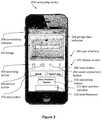
- FIG. 2illustrates a computing device running software, according to some embodiments.
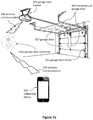
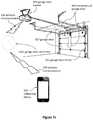
- FIG. 3illustrates an embodiment in which a garage door controller is connected to a building, according to some embodiments.
- FIG. 4illustrates a communication system with two wireless networks, according to some embodiments.
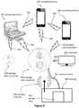
- FIG. 5illustrates a communication system that includes a security system, a doorbell button, a wireless router, a server, and users, according to some embodiments.
- FIGS. 6 a and 6 billustrate a front and a side perspective view of a garage door controller, according to some embodiments.
- FIGS. 7 a , 7 b , and 7 cillustrate perspective views of garage door communication systems, according to some embodiments.
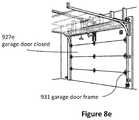
- FIGS. 8 a , 8 b , 8 c , 8 d and 8 eillustrate various views of a garage door being operated according to various embodiments.
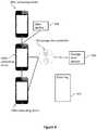
- FIG. 9illustrates a garage door communication system including multiple remote computing devices, according to some embodiments.
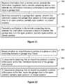
- FIGS. 10-16illustrate flow-charts of various methods of using a doorbell system, according to some embodiments.
- Garage door communication systemscan provide a secure and convenient way for a remotely located individual to open, close, partially open, and/or partially close a garage door.
- the garage door communication systemcan provide the remotely located individual with information about the garage door and the surrounding area.
- the garage door communication systemcan allow the individual to determine whether the garage door is open, closed, partially open, partially closed, and/or moving between one of the positions (e.g. moving from a closed position to an open position). It should be appreciated that the garage door can move between any position, such as an open position, closed position, partially open position, and/or a partially closed position. In this manner, the garage door 927 can move with respect to a garage door frame 931 .
- the garage door communication systemcan use a computing device to enable a remotely located person to see, hear, and/or talk with visitors.
- Computing devicescan include computers, laptops, tablets, mobile devices, smartphones, cellular phones, and wireless devices (e.g., cars with wireless communication).
- Example computing devicesinclude the iPhone, iPad, iMac, MacBook Air, and MacBook Pro made by Apple Inc. Communication between a remotely located person and a visitor can occur via the Internet, cellular networks, telecommunication networks, and wireless networks.
- FIG. 1illustrates a front view of a garage door communication system embodiment.
- the garage door communication system 200can include a garage door controller 202 and a computing device 204 .
- the illustrated garage door controller 202includes many components in one housing, several garage door communication system embodiments include components in separate housings.
- the garage door controller 202can include a camera assembly 208 and a controller button 212 .
- the camera assembly 208can be a video camera, which in some embodiments is a webcam.
- the camera assembly 208can thereby allow the remotely located individual to view the garage door and the area surrounding the garage door, such as the inside of the garage and/or the exterior space around the garage door.
- the garage door communication system 200can include a microphone and a speaker to allow the remotely located individual to hear, see, and talk with visitors who approach at least a portion of the garage door communication system 200 and/or press a controller button 212 .
- the garage door communication system 202can include a diagnostic light 216 and a power indicator light 220 .
- the diagnostic light 216is a first color (e.g., blue) if the garage door controller 202 and/or the garage door communication system 200 is connected to a wireless Internet network and is a second color (e.g., red) if the garage door controller 202 and/or the garage door communication system 200 is not connected to a wireless Internet network.
- the power indicator light 220is a first color if the garage door controller 202 is connected to a power source. The power source can be power supplied by the building to which the garage door controller 202 is attached.
- the power indicator light 220is a second color or does not emit light if the garage door controller 202 is not connected to the power source.
- the garage door controller 202can include an outer housing 224 , which can be water resistant and/or waterproof.
- the outer housingcan be made from metal or plastic, such as molded plastic with a hardness of 60 Shore D.
- the outer housing 224is made from brushed nickel or aluminum.
- the garage door controller 202can be electrically coupled to a power source, such as wires electrically connected to a building's electrical power system.
- the garage door controller 202includes a battery for backup and/or primary power.
- the garage door controller 202may also include a light located adjacent an outer surface of an outer housing of the garage door controller 202 .
- the lightmay be configured to illuminate an area adjacent the garage door controller 202 , perhaps to light the way for a user to see the area.
- the lightmay be selected from the group consisting of a light emitting diode, infrared light, halogen light, and fluorescent light.
- Wireless communication 230can enable the garage door controller 202 to communicate with the computing device 204 . Some embodiments enable communication via cellular and/or WiFi networks. Some embodiments enable communication via the Internet. Several embodiments enable wired communication between the garage door controller 202 and the computing device 204 .
- the wireless communication 230can include the following communication means: radio, WiFi (e.g., wireless local area network), cellular, Internet, Bluetooth, telecommunication, electromagnetic, infrared, light, sonic, and microwave. Other communication means are used by some embodiments.
- the garage door controller 202can initiate voice calls or send text messages to a computing device 204 (e.g., a smartphone, a desktop computer, a tablet computer, a laptop computer).
- a computing device 204e.g., a smartphone, a desktop computer, a tablet computer, a laptop computer.
- Some embodimentsinclude computer software (e.g., application software), which can be a mobile application designed to run on smartphones, tablet computers, and other mobile devices. Software of this nature is sometimes referred to as “app” software. Some embodiments include software designed to run on desktop computers and laptop computers.
- the computing device 204can run software with a graphical user interface 240 .
- the user interface 240can include icons or buttons.
- the softwareis configured for use with a touch-screen computing device such as a smartphone or tablet.
- a usercan log into an “app,” website, and/or software on a computing device 204 (e.g., mobile computing device, smartphone, tablet, desktop computer) to adjust the garage door controller settings discussed herein.
- a computing device 204e.g., mobile computing device, smartphone, tablet, desktop computer
- the softwarecan include a user interface 240 displayed on a display screen of the remote computing device 204 .
- the user interface 240can include a garage door indicator 244 , which can indicate the identity of the garage door (e.g. for systems with two or more garage doors).
- a personcan use one computing device 204 to control and/or interact with one or multiple garage door controllers, such as one garage door controller attached to a first garage door opener and another garage door controller attached to a second garage door opener.
- the user interface 240can include a connectivity indicator 248 .
- the connectivity indicator 248can indicate whether the computing device 204 is in communication with a garage door controller 202 , the Internet, and/or a cellular network.
- the connectivity indicator 248can alert the user if the computing device 204 has lost its connection with the garage door controller 202 ; the garage door controller 202 has been damaged; the garage door controller 202 has been stolen; the garage door controller 202 has been removed from its mounting location; the garage door controller 202 has lost electrical power; and/or if the computing device 204 cannot communicate with the garage door controller 202 .
- the connectivity indicator 248alerts the user of the computing device 204 by flashing, emitting a sound, displaying a message, and/or displaying a symbol.
- the user interface 240can display a door position indicator 277 , which can indicate the position of the garage door (e.g. whether the garage door is open, closed, partially open, partially closed, and/or whether the garage door is moving).
- the user interface 240can also include open/close button 276 to enable a user to activate the garage door, to thereby move the garage door to an open, closed, partially open, and/or partially closed position, for example.
- a computing devicecan enable a user to watch live video and/or hear live audio from a garage door controller due to the user's request rather than due to actions of a visitor.
- Some embodimentsinclude a computing device initiating a live video feed (or a video feed that is less than five minutes old).
- the user interface 240displays an image 252 such as a still image or a video of an area near and/or in front of the garage door controller 202 .
- the image 252can be taken by the camera assembly 208 and stored by the garage door controller 202 , server 206 , and/or computing device 204 .
- the user interface 240can include a recording button 256 to enable a user to record images, videos, and/or sound from the camera assembly 208 , microphone of the security system 202 , and/or microphone of the computing device 204 .
- the user interface 240includes a picture button 260 to allow the user to take still pictures and/or videos of the area near and/or in front of the security system 202 .
- the user interface 240can also include a sound adjustment button 264 and a mute button 268 .
- the user interface 240can include camera manipulation buttons such as zoom, pan, and light adjustment buttons.
- the camera assembly 208automatically adjusts between Day Mode and Night Mode.
- Some embodimentsinclude an infrared camera and/or infrared lights to illuminate an area near the security system 202 to enable the camera assembly 208 to provide sufficient visibility (even at night).
- buttonsinclude diverse means of selecting various options, features, and functions. Buttons can be selected by mouse clicks, keyboard commands, and/or touching a touch screen. Many embodiments include buttons that can be selected without touch screens.
- the user interface 240can include a quality selection button, not shown in FIG. 2 , which can allow a user to select the quality and/or amount of the data transmitted from the garage door controller 202 to the computing device 204 and/or from the computing device 204 to the garage door controller 202 .
- videocan be sent to and/or received from the computing device 204 using video chat protocols such as FaceTime (by Apple Inc.) or Skype (by Microsoft Corporation).
- videochat protocolssuch as FaceTime (by Apple Inc.) or Skype (by Microsoft Corporation).
- these videosare played by videoconferencing apps on the computing device 204 instead of being played by the user interface 240 .
- the user interface 240can include an open/close button 276 to activate the garage door opener 926 to move the garage door to the open, closed, partially open, and/or partially closed position.
- the button 276in response to a first press of the open/close button 276 , can be enabled to activate the garage door opener 926 to move the garage door.
- the button 276in response to a second press of the open/close button 276 , can be enabled to activate the garage door opener 926 to stop moving the garage door.
- a speak button 272is both an answer button (to accept a communication request from a visitor located adjacent the garage door controller 202 ) and is a termination button (to end communication between the garage door controller 202 and the computing device 204 ). Selecting the button 272 when the system is attempting to establish two-way communication between the visitor and the user can start two-way communication.
- the button 272can include the words “End Call” during two-way communication between the visitor and the user. Selecting the button 272 during two-way communication between the visitor and the user can terminate two-way communication.
- terminating two-way communicationstill enables the user to see and hear the visitor.
- terminating two-way communicationcauses the computing device 204 to stop showing video from the garage door controller 202 and to stop emitting sounds recorded by the garage door controller 202 .
- the user interface 240opens as soon as the garage door controller 202 detects a movement of the garage door or a presence of a visitor (e.g., senses indications of a visitor). Once the user interface 240 opens, the user can see and/or hear the visitor even before “answering” or otherwise accepting two-way communication, in several embodiments.
- Some method embodimentsinclude detecting a movement of a garage door or a presence of a visitor with a garage door controller 202 .
- the methodscan include causing the user interface 240 to display on a remote computing device 204 due to the detection of the garage door moving or the presence of the visitor (e.g., with or without user interaction).
- the methodscan include displaying video from the garage door controller 202 and/or audio from the garage door controller 202 before the user accepts two-way communication with the visitor.
- the methodscan include displaying video from the garage door controller 202 and/or audio from the garage door controller 202 before the user accepts the visitor's communication request.
- the methodscan include the computing device 204 simultaneously asking the user if the user wants to accept (e.g., answer) the communication request and displaying audio and/or video of the visitor.
- the usercan see and hear the visitor via the garage door controller 202 before opening a means of two-way communication with the visitor.
- the softwareincludes means to start the video feed on demand.
- a user of the computing devicemight wonder what is happening near the garage door controller 202 .
- the usercan open the software application on the computing device 204 and instruct the application to show live video and/or audio from the garage door controller 202 even if no event near the garage door controller 202 has triggered the communication.
- the garage door controller 202can be configured to record when the garage door controller 202 detects movement of the garage door and/or the presence of a person.
- the user of the computing device 204can later review all video and/or audio records when the garage door controller 202 detected movement and/or the presence of a person.
- the server 206controls communication between the computing device 204 and the garage door controller 202 , which can include a camera, a microphone, and a speaker. In several embodiments, the server 206 does not control communication between the computing device 204 and the garage door controller 202 .
- data captured by the security system and/or the computing device 204is stored by another remote device such as the server 206 .
- Cloud storage, enterprise storage, and/or networked enterprise storagecan be used to store video, pictures, and/or audio from the garage door communication system 200 or from any part of the garage door communication system 200 .
- the usercan download and/or stream stored data and/or storage video, pictures, and/or audio. For example, a user can record visitors for a year and then later can review conversations with visitors from the last year.
- remote storage, the server 206 , the computing device 204 , and/or the garage door controller 202can store information and statistics regarding visitors and usage.
- a remote server 206sends an alert (e.g., phone call, text message, image on the user interface 240 ) regarding the power and/or connectivity issue.
- the remote server 206can manage communication between the garage door controller 202 and the computing device 204 .
- information from the garage door controller 202is stored by the remote server 206 .
- information from the garage door controller 202is stored by the remote server 206 until the information can be sent to the computing device 204 , uploaded to the computing device 204 , and/or displayed to the remotely located person via the computing device 204 .
- the remote server 206can be a computing device 204 that stores information from the garage door controller 202 and/or from the computing device 204 .
- the remote server 206is located in a data center.
- the computing device 204 and/or the remote server 206attempts to communicate with the garage door controller 202 . If the computing device 204 and/or the remote server 206 is unable to communicate with the garage door controller 202 , the computing device 204 and/or the remote server 206 alerts the remotely located person via the software, phone, text, a displayed message, and/or a website. In some embodiments, the computing device 204 and/or the remote server 206 attempts to communicate with the garage door controller 202 periodically; at least every five hours and/or less than every 10 minutes; at least every 24 hours and/or less than every 60 minutes; or at least every hour and/or less than every second.
- the server 206can initiate communication to the computer device 204 and/or to the garage door controller 202 . In several embodiments, the server 206 can initiate, control, and/or block communication between the computing device 204 and the garage door controller 202 .
- Some embodimentscan include programming the remote server 206 to instruct the garage door controller 202 to perform a first predetermined action at a first time of day and programming the remote server 206 to instruct the garage door controller 202 to perform a second predetermined action at a second time of day.
- the remote server 206can be programmed to instruct the garage door controller 202 to check whether the garage door 927 is closed at sunset. If the garage door controller 202 determines that the garage door 927 is not closed at sunset, the garage door controller 202 can send a transmission to the garage door opener 926 to close the garage door 927 .
- the remote server 206 and garage door controller 202can be programmed to perform any predetermined action at any time of day.
- FIG. 3illustrates an embodiment in which a garage door controller 202 is connected to a building 300 , which can include a garage door 927 .
- Electrical wires 304can electrically couple the garage door controller 202 to the electrical system of the building 300 so that the garage door controller 202 can receive electrical power from the building 300 .
- a wireless network 308can allow devices to wirelessly access the Internet.
- the garage door controller 202can access the Internet via the wireless network 308 .
- the wireless network 308can transmit data from the garage door controller 202 to the Internet, which can transmit the data to remotely located computing devices 204 .
- the Internet and wireless networkscan transmit data from remotely located computing devices 204 to the garage door controller 202 .
- a garage door controller 202connects to a home's WiFi.
- one computing device 204can communicate with multiple garage door controllers 202 .
- multiple computing devices 204can communicate with one garage door controller 202 .
- the garage door controller 202can communicate (e.g., wirelessly 230 ) with a television 306 , which can be a smart television. Users can view the television 306 to see a position of the garage door 927 and/or to see and/or talk with a visitor located in the area of the garage door controller 202 .
- garage door controller embodimentsinclude using electricity from electrical wires 304 of a building 300
- many garage door controller embodimentscommunicate with computing devices 204 via a wireless network 308 that allows garage door controllers 202 to connect to a regional and sometimes global communications network.
- the garage door controller 202communicates via a wireless network 308 with a router that enables communication with the Internet, which can enable communication via diverse means including telecommunication networks.
- a garage door controller 202can communicate with computing devices 204 that are desktop computers, automobiles, laptop computers, tablet computers, cellular phones, mobile devices, and smart phones.
- a security systeme.g., a doorbell
- a computing devicesuch as a smartphone, can provide this information to the security system.
- the computing devicee.g., a smartphone
- the useropens software (such as an app) on the computing device.
- the garage door controller 202can automatically join the computing device's ad hoc network.
- the usercan utilize the software to select the wireless network that the security system should join and to provide the password of the wireless network (e.g., of the router) to the garage door controller 202 .
- a garage door controller 202can be connected to a wireless network (such as a wireless network of a home).
- a wireless networksuch as a wireless network of a home.
- Several embodimentsinclude transmitting an identifier (e.g., a name) to a garage door controller 202 , wherein the identifier enables the garage door controller 202 to identify the wireless network to which the garage door controller 202 should connect.
- Several embodimentsinclude transmitting a password of the wireless network to the garage door controller 202 , wherein the password enables the garage door controller 202 to connect to the network.
- a computing device 204e.g., a smartphone transmits the identifier and password.
- methods of connecting a garage door controller 202 to a wireless networkcan include placing the garage door controller 202 in Setup Mode.
- Some garage door controller 202automatically go into Setup Mode upon first use, first receiving electrical power, first receiving electrical power after a reset button is pushed, first receiving electrical power after being reset, and/or when a reset button is pushed.
- a Setup Modecomprises a Network Connection Mode.
- Methodscan comprise entering the Network Connection Mode in response to pressing the button for a predetermined amount of time. It should be appreciated that the predetermined amount of time can be any duration of time, for example at least eight seconds.
- the Network Connection Modecan also comprise detecting a first wireless network having a name and a password.
- the Network Connection Modecan comprise inputting a doorbell identification code into the remotely located computing device.
- the doorbell identification codecan be associated with the doorbell.
- the Network Connection Modecan comprise using the doorbell identification code to verify whether the remotely located computing device is authorized to communicate with the doorbell.
- the Network Connection Modecan comprise the remotely located computing device creating a second wireless network (e.g., that emanates from the remotely located computing device).
- the Network Connection Modecan comprise transmitting the name and the password of the first wireless network directly from the remotely located computing device to the garage door controller 202 via the second wireless network to enable the garage door controller 202 to communicate with the remotely located computing device 204 via the first wireless
- Methodscan comprise the remotely located computing device 204 directly communicating with the garage door controller 202 via the second wireless network prior to the garage door controller 202 indirectly communicating with the remotely located computing device 204 via the first wireless network.
- the wireless communication from the remotely located computing device 204can travel through the air directly to the garage door controller 202 .
- the wireless communication from the remotely located computing device 204can travel indirectly to the garage door controller 202 via a third electronic device such as a server.
- FIG. 4illustrates a garage door communication system 200 with two wireless networks 5556 , 5560 .
- the first wireless network 5560can emanate from a router 5550 .
- the second wireless networkcan emanate from the computing device 204 (e.g., a cellular telephone).
- the first wireless network 5560can enable indirect wireless communication 5552 between the computing device 204 and the garage door controller 202 via the router 5550 or via a server 206 (shown in FIG. 1 ).
- the second wireless network 5556can enable direct wireless communication 5554 between the computing device 204 and the garage door controller 202 .
- the computing device 204can send a password and a name of the first wireless network 5560 to the garage door controller 202 via the second wireless network 5556 .
- the second wireless network 5556does not require a password.
- a garage door controller 202creates its own wireless network (e.g., WiFi network) with a recognizable network name (e.g., a service set identifier).
- Softwarecan provide setup instructions to the user via a computing device 204 , in some cases, upon detecting a new wireless network with the recognizable network name.
- the instructionscan inform the user how to temporarily join the security system's wireless network with the computing device 204 .
- the usercan select and/or transmit the name and password of a target wireless network to the garage door controller 202 from the computing device 204 .
- the garage door controller 202can join the target wireless network (e.g., the wireless network of the building to which the garage door controller is attached) and can terminate its own wireless network.
- the computing device 204can capture the name and password of the target network before joining the network of the garage door controller 202 . In some cases, the user enters the name and password of the target network into the computing device 204 to enable the computing device 204 to provide the name and password of the target network to the garage door controller 202 .
- the computing device 204recognizes the name of the network of the garage door controller 202 , automatically joins the network of the garage door controller 202 , and transmits the name and password of the target network to the garage door controller 202 . In some cases, these steps are preceded by launching software (on the computing device 204 ) configured to perform these steps and/or capable of performing these steps.
- Methodscan include the garage door controller 202 trying to join an ad hoc network (or other wireless network) with a fixed network name or a network name based on an identifier of the garage door controller 202 (e.g., the serial number of the garage door controller 202 , the model number of the garage door controller 202 ).
- the computing device 204can provide instructions to the user to temporarily setup the network (e.g., the ad hoc network) via the computing device 204 .
- the networkcan have the fixed network name or the name based on the identifier.
- the garage door controller 202can recognize the name and join the network.
- the computing device 204can use the network to transmit the name and password of a target network (e.g., the wireless network of the building to which the garage door controller 202 will be coupled) to the garage door controller 202 .
- the garage door controller 202can use the name and password of the target network to join the target network.
- the computing device 204displays an image (e.g., a quick response code) that contains or communicates the name and password of the target network.
- the garage door controller 202can use its camera and onboard software to scan and decode the image (to determine the name and password of the target network).
- the garage door controller 202can use the name and password of the target network to join the target network.
- the computing device 204can generate and display pulses of light (e.g., by flashing black and white images on the screen of the computing device 204 ).
- the garage door controller 202can use its camera and software to analyze and decode the pulses of light.
- the pulses of lightcan contain the name and/or password of the wireless network.
- the garage door controller 202can use the name and password of the target network to join the target network.
- only the password of the target networkis given to the garage door controller 202 .
- the garage door controller 202can use the password to test each detected wireless network until it identifies a wireless network to which it can connect using the password.
- the computing device 204can generate and emit an audio signal that corresponds to the name and/or password of the target network.
- the garage door controller 202can use its microphone and software to analyze and decode the audio signal to receive the name and/or password of the target network.
- the garage door controller 202can use the name and password of the target network to join the target network.
- the computing device 204transmits the name and password of the target network to the garage door controller 202 via Morse code.
- the garage door controller 202can pair with the computing device 204 via Bluetooth.
- the computing device 204can transmit the name and password of the target network to the garage door controller 202 (e.g., via Bluetooth).
- the garage door controller 202can use the name and password of the target network to join the target network.
- the computing device 204transmits the name and/or password of the target network via infrared (“IR”) communication (e.g., IR light) to the garage door controller 202 .
- IRinfrared
- the computing device 204can emit the IR communication via IR LEDs or IR display emissions.
- An infrared emission devicee.g., with an IR LED
- the garage door controller 202can detect the IR communication via IR sensors.
- the garage door controller 202can use the name and password of the target network to join the target network.
- embodiments of the garage door controller 202can be configured to initiate movement of a garage door opener 926 to thereby move a garage door 927 that is coupled to the garage door opener 926 .
- the garage door 927can move between an open position 927 a , partially open position 927 b , partially open or partially closed position 927 c , partially closed position 927 d , and/or a closed position 927 e .
- the position of the garage door 927 in FIG. 8 bcan be said to be either partially open or partially closed.
- the garage door controller 202can initiate movement of the garage door opener 926 and the garage door 927 to any known position as during conventional usage of a garage door opener 926 and garage door 927 .
- Embodiments of a garage door controller 202can enable a user to retrieve information from and control a garage door 927 from virtually anyplace in the world.
- cellular networkssuch as 3G, 4G, and LTE, and WiFi networks
- peoplecan be connected to mobile communication standards from almost any location.
- the user's remote computing device 204is connected to a mobile communication standard, such as, but not limited to, 3G, 4G, LTE, WiMAX, and WiFi
- the usermay be able to retrieve information from the garage door controller and also control the garage door and/or garage door opener via the garage door controller.
- the remote computing device 204can be at least 100 feet away from the garage door opener 926 .
- the remote computing device 204is at least one mile away, ten miles, one hundred miles, or at least one thousand miles from the garage door opener 926 .
- the remote computing device 204is thereby communicatively coupled to the remote server.
- the remote serveris communicatively coupled to the garage door controller 202 via WiFi. Therefore, it can be said that the remote computing device 204 is also communicatively coupled to the garage door controller 202 via WiFi. Therefore, some embodiments of the garage door controller 202 can include receiving, by the garage door controller 202 , a WiFi transmission from the remote computing device 204 , wherein the WiFi transmission includes a command to move the garage door to the open position 927 a , partially open position 927 b , 927 c , 927 d , or closed position 927 e . In response to receiving the WiFi transmission from the remote computing device, some embodiments can include moving the garage door to the open position 927 a , partially open position 927 b , 927 c , 927 d , or closed position 927 e.
- the garage door controller 202may include a camera assembly 208 .
- the camera assembly 208can be a video camera, which in some embodiments is a webcam.
- the remotely located usermay be able to activate the camera assembly 208 from their remote computing device 204 to thereby view the garage door 927 and the area surrounding the garage door 927 . Accordingly, a user may use this feature for any number of possibilities. For example, a remote user may view whether the garage door is open or closed.
- a remote usermay wish to view the area inside the garage to determine if a prowler is present to thereby verify the security of the garage.
- a remote usermay wish to view whether a car is located in the garage, which may thereby indicate the presence of another user within the building.
- Some embodiments of the garage door controller 202can be configured to initiate communication between a visitor, located in an area near the garage door controller 202 , and a user of a remote computing device 204 (e.g. a homeowner).
- the communicationsmay enable voice and/or visual communication between the user and/or the visitor.
- the communicationsmay serve as instructions to the garage door controller 202 to thereby activate the garage door 927 to perform an operation, such as moving to an open position 927 a or a closed position 927 e.
- the controller button 212may be configured to enable various operations. For example, a person might initiate a communication request by pressing the controller button 212 (shown in FIG. 1 ) or triggering a motion or proximity sensor.
- the controller button 212may be configured to enable various operations in response to different types of presses of the controller button 212 . For example, in some embodiments, a user may press and hold the controller button 212 for at least three seconds to thereby initiate a communication request. As well, in some embodiments, a user may press the controller button 212 for less than three seconds to thereby initiate a movement of the garage door opener and the garage door 927 .
- multiple computing devices 204are candidates to receive information from a garage door controller 202 . Accordingly, in response to the controller button 212 being pressed, the garage door controller 202 can notify multiple remotely located computing devices at once.
- the garage door controller 202might simultaneously notify a smartphone of a first homeowner, a tablet of a housekeeper, and a laptop located inside the building to which the security system is connected.
- computing devicesare assigned a priority and computing devices with a higher priority can terminate the communication of lower priority devices. For example, the homeowner could answer the communication request later than the housekeeper, but the homeowner could terminate the communication between the garage door controller 202 and the housekeeper's computing device.
- userscan forward communication requests from one computing device to another computing device.
- multiple computing devicesare notified in series regarding a communication request. For example, the communication request might initially go to a first remote computing device, but if the communication request is not answered within a certain period of time, the communication request might go to a second remote computing device. If the communication request is not answered, the communication request might go to a third remote computing device.
- FIG. 5illustrates a communication system 310 that includes a garage door controller 320 , a controller button 324 , a WiFi router 328 , a server 332 , and users 336 .
- a visitorinitiates a communication request by pressing the doorbell button 324 or triggering a motion or proximity sensor. The visitor can trigger the motion or proximity sensor by approaching the garage door controller 320 .
- the garage door controller 320connects or otherwise communicates with a home WiFi router 328 .
- the server 332receives a signal from the WiFi router 328 and sends video and/or audio to the users 336 via a wireless network 364 .
- step 370the users see the visitor, hear the visitor, and talk with the visitor.
- Step 370can include using a software application to see, hear, and/or talk with the visitor.
- the visitor and users 336can engage in two-way communication 374 via the internet or other wireless communication system even when the visitor and the users 336 are located far away from each other.
- Some embodimentsenable users to receive communication requests and communicate with visitors via diverse mobile communication standards including third generation (“3G”), fourth generation (“4G”), long term evolution (“LTE”), worldwide interoperability for microwave access (“WiMAX”), and WiFi.
- 3Gthird generation
- 4Gfourth generation
- LTElong term evolution
- WiMAXworldwide interoperability for microwave access
- WiFiWiFi
- the users 336utilize the garage door communication system 310 to communicate with visitors who are in close proximity to the users 336 .
- a user 336 located inside the buildingcan communicate with a visitor located just outside the building via the communication system 310 .
- Some embodimentsinclude a location detection system (e.g., GPS) to determine if the computing device 204 is located inside the building, near the building, within 100 feet of the building, within 100 feet of the garage door controller 202 , within 50 feet of the building, and/or within 50 feet of the garage door controller 202 , in which case the computing device 204 is considered in Close Mode.
- the computing device 204is considered in Close Mode if the computing device 204 is connected to a wireless network 308 of the building to which the garage door controller 202 is coupled.
- the computing device 204is considered in Close Mode if the computing device 204 and the garage door controller 202 are connected to the same wireless network 308 . If the computing device 204 is not in Off Mode and not in Close Mode, then the computing device 204 is in Away Mode, in which the computing device 204 is considered to be located remotely from the building 300 .
- the computing device 204can behave differently in Close Mode than in Away Mode. In some embodiments, the computing device 204 will not notify the user of visitors if the computing device 204 is in Close Mode. In several embodiments, Close Mode silences alerts, which can include precluding and/or eliminating the alerts. Instead, the user might have to listen for typical indications of a visitor such as the ring of a traditional doorbell. Once the computing device 204 enters Away Mode, the computing device 204 can notify the user of the visitor. In some embodiments, the computing device 204 notifies the user regarding the visitor if the computing device 204 is in Close Mode or Away Mode.
- the usercan decline a communication request by selecting via the user interface 240 a pre-recorded message to be played by the security system 202 .
- the pre-recorded messagecan include audio and/or video content.
- Some embodimentscan provide the user with options for playing a pre-recorded message on demand, and/or automatically playing a pre-recorded message under user-specified conditions. Examples of conditions that can be specified include time of day, user location, facial recognition or non-recognition of visitors, and/or number of recent visitors.
- a pre-recorded messagecan interrupt two-way communications, which can resume after delivery of the message.
- a pre-recorded messagecan be delivered without interrupting two-way communications.
- the garage door controller 202includes a memory. If the garage door controller 202 cannot communicate with the computing device 204 and/or with the server 206 (shown in FIG. 1 ), the memory 492 of the garage door controller 202 can store a recorded message and/or video from the visitor. Once the garage door controller 202 can communicate with the computing device 204 and/or the server 206 , the garage door controller 202 can communicate the recorded message and/or video to the computing device 204 and/or the server 206 .
- the garage door controller 202can ask a visitor to record a message and/or can record pictures (e.g., video, still pictures) when the garage door controller 202 cannot communicate via the wireless network 308 .
- the garage door controller 202can include a Network Enabled Mode and a Network Disabled Mode. In the Network Enabled Mode, the garage door controller 202 can communicate via the wireless network 308 with a remote server and/or computing device 204 . In the Network Disabled Mode, the garage door controller 202 cannot communicate via the wireless network 308 with a remote server and/or computing device 204 .
- the garage door controller 202can send video and/or audio from the visitor to the user instantaneously; nearly instantaneously; immediately; within 15 seconds of capturing the video and/or audio; and/or within 60 seconds of capturing the video and/or audio.
- the security system 202can preferentially send data (e.g., video, audio, traits, identification) regarding the visitor to the computing device 204 rather than storing the data in the memory of the security system 202 .
- the garage door controller 202can cause a chime inside the building 300 to emit a sound.
- the security system 202emits a visible error signal (e.g., flashing light, red light); records images and audio to the security system's memory; asks the visitor to leave a message for the user; and/or alerts the user regarding the lack of wireless communication.
- a visible error signale.g., flashing light, red light
- the security system 202can maintain a visitor log, which can capture information such as the date, time, audio, video, and/or images of the visitor.
- the user interface 240can display this information in a “guest book” format; as a timeline or calendar; as a series of images, videos, and/or audio files; or as a log file.
- the usercan accept or decline a communication request from a visitor.
- the usercan push a button (e.g., 276 ) on the user interface 240 (shown in FIG. 2 ) to decline a communication request or accept a communication request.
- the usercan decline a communication request without the visitor knowing that the user received the communication request.
- the computing device 204can allow the user to click a button, such as an icon on a graphical user interface on a touch screen, to see and/or hear the visitor.
- accepting a communication requestincludes opening a two-way line of communication (e.g., audio and/or video) between the visitor and the user to enable the user to speak with the visitor.
- a visitorcan initiate a communication request and/or activate the garage door opener to move the garage door by pressing the controller button of the garage door controller 202 , triggering a motion sensor of the garage door controller 202 , triggering a proximity sensor of the garage door controller 202 , and/or triggering an audio alarm of the garage door controller 202 .
- the audio alarmincludes the microphone of the garage door controller 202 .
- the garage door controller 202can determine if sounds sensed by the microphone are from a knocking sound, a stepping sound, and/or from a human in close proximity to the garage door controller 202 .
- the garage door controller 202can detect important sounds such as knocking, talking, and footsteps by recording the sounds and then computing features that can be used for classification.
- Each sound class(e.g., knocking) has features that enable the garage door controller 202 to accurately identify the sound as knocking, talking, stepping, or extraneous noise.
- Featurescan be analyzed using a decision tree to classify each sound.
- a visitorcan trigger an audio alarm (and thus, initiate a communication request) by knocking on a door located within hearing range of a microphone of the garage door controller 202 .
- a visitorcan trigger an audio alarm (and thus, initiate a communication request) by stepping and/or talking within hearing range of a microphone of the garage door controller 202 .
- the garage door controller 202may receive audible instructions from a user to stop or move the garage door 927 .
- the garage door controller 202may receive, by a microphone, a first audible message from the user.
- the first audible messagemay include an instruction to open the garage door 927 , close the garage door 927 , or stop the garage door 927 .
- embodimentsmay include moving the garage door 927 to the open position 927 a .
- embodimentsmay include moving the garage door to the closed position 927 e .
- embodimentsmay include terminating movement of the garage door 927 .
- the audible instructionsmay include any such command to control the garage door 927 in a manner as known within the art.
- the garage door controller 202may emit, by a speaker, a second audible message.
- the second audible messagemay include any type of information in about the garage door communication system 200 .
- the second audible messagemay include a notification about whether the garage door is open or closed.
- the garage door controller 202may include a motion detector, which may be configured to detect motion from a user within a space adjacent the garage door controller 202 .
- the motion detectormay be located adjacent to the outer surface of the outer housing.
- the user's movementsmay serve as instructions for the garage door controller 202 to activate the garage door opener 926 to perform an operation.
- the garage door controller 202may detect a single wave motion from a user's hand, which may indicate that the user wishes to open the garage door 927 .
- the garage door controller 202may transmit a signal to the garage door opener 926 to thereby move the garage door 927 to the open position 927 a.
- the garage door controller 202may detect a double wave motion from a user's hand, which may indicate that the user wishes to close the garage door 927 . In response to the garage door controller 202 detecting the double wave motion from the user's hand, the garage door controller 202 may transmit a signal to the garage door opener 926 to thereby move the garage door 927 to the closed position 927 e.
- the garage door controller 202may be configured to detect any predetermined motion, whereby the predetermined motion may correspond to any such predetermined action of the garage door opener 926 and the garage door 927 .
- the predetermined actionmay be selected from the group consisting of closing the garage door, opening the garage door, terminating movement of the garage door, illuminating the light, and deactivating the light.
- the predetermined motionmay be any such bodily motion, such as a hand wave, a smile (from a user's face), and the like.
- the garage door controller 202may be configured to detect one, two, three, four, five, or more predetermined motions, which may correspond to one, two, three, four, five, or more predetermined actions.
- the garage door controller 202may be configured to receive different types of button presses and initiate different operations based on the respective type of button press. For example, the garage door controller 202 may receive a first button press that is for a first predetermined period of time. In response to the first button press, the garage door controller 202 may initiate a first garage door operation, such as opening the garage door 927 . In some embodiments, the garage door controller 202 may receive a second button press, which is for a second predetermined period of time that is different than the first predetermined period of time. In response to the second button press, the garage door controller 202 may initiate a second garage door operation, such as closing the garage door 927 .
- the first button presscomprises at least one button press
- the second button presscomprises at least two button presses.
- the garage door controller 202may be configured to recognize different types of buttons presses and thereby perform different operations for each type of button press.
- Embodimentsmay also include a method for installing a garage door controller.
- some embodimentsmay include replacing a conventional garage door controller, such as a first garage door controller, that is wired to a garage door opener.
- the embodimentsmay include replacing the conventional garage door controller with a second garage door controller, such as garage door controller 202 .
- the first garage door controllermay comprise a button configured to open and close a circuit between a power supply and a garage door opener to thereby allow electricity to flow through the garage door opener to thereby move a garage door between an open position 927 a and a closed position 927 e .
- the second garage door controller 202may include an outer housing, a button configured to open and close the circuit between the power supply and the garage door opener, and a wireless communication module configured to communicatively couple to a remote computing device via WiFi or cellular communication.
- first garage door controllermay be electrically coupled to two or more electrical wires that are electrically coupled to the garage door opener.
- some methodsmay include electrically decoupling the first garage door controller from a first wire, wherein the first wire is electrically coupled to the garage door opener.
- embodimentsmay include electrically decoupling the first garage door controller from a second wire, wherein the second wire is electrically coupled to the garage door opener.
- the second garage door controller 202may then be installed. Accordingly, some embodiments may include electrically coupling the second garage door controller to the first wire and electrically coupling the second garage door controller to the second wire.
- Some methodsmay also include communicatively coupling the second garage door controller to an Internet router to thereby communicatively couple the second garage door controller to a wireless network.
- methodsmay include communicatively coupling the second garage door controller, by the Internet router, to a remote server, and communicatively coupling the second garage door controller, by the Internet router and the remote server, to the remote computing device. In this manner, a user may upgrade his or her conventional garage door system to a “smart” garage door system that is capable of being accessed and controlled via the Internet.
- Some embodiments of the second garage door controller 202may include a camera configured to record a video. According to these embodiments, some methods may further include arranging and configuring the second garage door controller 202 such that at least a portion of the garage door 927 is located within a line of sight of the camera 208 . This may allow a remotely located user to view, by the camera 208 , at least a portion of the garage door 927 .
- Some embodiments of conventional garage door systemsmay include safety sensors configured to detect whether a person, animal or object crosses a path of the garage door 927 while the garage door 927 is moving.
- the safety sensorsmay trigger the garage door opener 926 to terminate movement to thereby avoid the garage door 927 coming into contact with the person, animal or object.
- the garage door opener 926may be electrically coupled to a first safety sensor and a second safety sensor.
- the first safety sensorcan be located at a first location adjacent a first vertical surface of the garage door frame 931 .
- the second safety sensorcan be located at a second location adjacent a second vertical surface of the garage door frame 931 .
- the first vertical surfacecan be horizontally spaced from the second vertical surface such that the first vertical surface faces the second vertical surface.
- Some embodiments of the garage door controller 202include arranging and configuring various components, such as the camera 208 , to detect whether an object enters a line of sight between the first location and the second location. In this manner, the garage door controller 202 can be configured to detect whether an object enters a line of sight between the first location and the second location. In response to the garage door controller 202 detecting a person, animal, and/or object entering the line of sight between the first location and the second location, the garage door controller 202 can send a command to the garage door opener 926 to terminate movement. Accordingly, embodiments may include method steps for replacing the existing safety sensors of a garage door 927 .
- the garage door controller 202can include detection features that replace the safety sensors of a conventional garage door system. Accordingly, some embodiments can include removing the existing safety sensors of a conventional garage door system. For example, in some embodiments a third wire is electrically coupled between the first safety sensor and a first terminal on the garage door opener 926 , and a fourth wire is electrically coupled between the second safety sensor and a second terminal on the garage door opener 926 . In this manner, embodiments may include electrically decoupling the first safety sensor and any corresponding wire or wires, such as the third wire, from the garage door opener 926 , and electrically decoupling the second safety sensor and any corresponding wire or wires, such as the fourth wire, from the garage door opener 926 .
- methodsmay include electrically coupling a jumper between the first terminal and the second terminal of the garage door opener 926 , whereby the jumper completes an electrical circuit between the second garage door controller and the garage door opener 926 to thereby allow the garage door 927 to move between the open and closed positions.
- the garage door framedefines both a first vertical inner surface, a second vertical inner surface that faces the first vertical inner surface, and a first horizontal inner surface that faces a ground surface whereby the first horizontal inner surface extends between the first vertical inner surface and the second vertical inner surface.
- the spacecan be a plane that is parallel to the garage door 927 when the garage door 927 is in the closed position 927 e .
- the planecan be located between the garage door opener 926 and the garage door 927 when the garage door 927 is in the closed position 927 e .
- some embodimentsinclude using the camera 208 to detect whether an object breaks a portion of the plane in a location between the first vertical inner surface, the second vertical inner surface, the first horizontal inner surface, and the ground surface.
- some methodsmay also include using the garage door controller to terminate movement of the garage door opener 926 .
- embodimentsmay include using the garage door controller to move the garage door 927 to the open position 927 a , partially open position 927 b , 927 c , 927 d , or closed position 927 e.
- the garage door controller 202can terminate movement of the garage door 927 to avoid an accident. Furthermore, because the camera 208 is able to monitor entire plane between the vertical surfaces and the horizontal surface of the garage door frame 931 , the camera 208 may increase safety over conventional garage door systems. In conventional garage door systems, the safety sensors are located towards the ground surface. In effect, conventional safety sensors are only able to monitor whether an object crosses the plane towards the ground surface. However, the garage door controller 202 may detect whether an object crosses the plane at any height. For example, if a car bumper crosses the plane, a conventional garage door system may fail to detect the presence of the bumper; thus, the conventional garage door may contact the car bumper. However, the garage door controller 202 may detect an object at any height or location on the plane, such as the car bumper, and the garage door controller 202 may thereby terminate movement of the garage door to avoid an accident.
- the space or plane that extends between the vertical surfacesis a line that extends between a first point and a second point adjacent the garage door frame 931 .
- the first pointcan be coordinated at a first vertical location and a first horizontal location.
- the second pointcan be substantially coordinated at the first vertical location and a second horizontal location. It should be appreciated that the term substantially means about or for the most part.
- the first vertical locationis located along a lower portion of the garage door frame.
- the first horizontal locationis horizontally spaced from the second horizontal location such that the first and second horizontal locations are disposed at opposite sides of the garage door frame 931 .
- section headings and subheadings provided hereinare nonlimiting.
- the section headings and subheadingsdo not represent or limit the full scope of the embodiments described in the sections to which the headings and subheadings pertain.
- a section titled “Topic 1 ”may include embodiments that do not pertain to Topic 1 and embodiments described in other sections may apply to and be combined with embodiments described within the “Topic 1 ” section.
- routines, processes, methods, and algorithms described in the preceding sectionsmay be embodied in, and fully or partially automated by, code modules executed by one or more computers, computer processors, or machines configured to execute computer instructions.
- the code modulesmay be stored on any type of non-transitory computer-readable storage medium or tangible computer storage device, such as hard drives, solid state memory, flash memory, optical disc, and/or the like.
- the processes and algorithmsmay be implemented partially or wholly in application-specific circuitry.
- the results of the disclosed processes and process stepsmay be stored, persistently or otherwise, in any type of non-transitory computer storage such as, e.g., volatile or non-volatile storage.
- A, B, and/or Ccan be replaced with A, B, and C written in one sentence and A, B, or C written in another sentence.
- A, B, and/or Cmeans that some embodiments can include A and B, some embodiments can include A and C, some embodiments can include B and C, some embodiments can only include A, some embodiments can include only B, some embodiments can include only C, and some embodiments include A, B, and C.
- the term “and/or”is used to avoid unnecessary redundancy.
Landscapes
- Physics & Mathematics (AREA)
- General Physics & Mathematics (AREA)
- Engineering & Computer Science (AREA)
- Computer Networks & Wireless Communication (AREA)
- Manufacturing & Machinery (AREA)
- Power-Operated Mechanisms For Wings (AREA)
Abstract
Description
Claims (20)
Priority Applications (6)
| Application Number | Priority Date | Filing Date | Title |
|---|---|---|---|
| US15/060,332US10733823B2 (en) | 2013-07-26 | 2016-03-03 | Garage door communication systems and methods |
| US15/293,334US10742938B2 (en) | 2015-03-07 | 2016-10-14 | Garage door communication systems and methods |
| US16/921,761US11228739B2 (en) | 2015-03-07 | 2020-07-06 | Garage door communication systems and methods |
| US17/543,735US11388373B2 (en) | 2015-03-07 | 2021-12-07 | Garage door communication systems and methods |
| US17/861,147US11871155B2 (en) | 2015-03-07 | 2022-07-08 | Garage door communication systems and methods |
| US18/541,447US20240121365A1 (en) | 2015-03-07 | 2023-12-15 | Garage door communication systems and methods |
Applications Claiming Priority (12)
| Application Number | Priority Date | Filing Date | Title |
|---|---|---|---|
| US201361859070P | 2013-07-26 | 2013-07-26 | |
| US201361872439P | 2013-08-30 | 2013-08-30 | |
| US14/098,772US8780201B1 (en) | 2013-07-26 | 2013-12-06 | Doorbell communication systems and methods |
| US14/099,888US8823795B1 (en) | 2013-07-26 | 2013-12-06 | Doorbell communication systems and methods |
| US14/142,839US8842180B1 (en) | 2013-07-26 | 2013-12-28 | Doorbell communication systems and methods |
| US14/275,811US8872915B1 (en) | 2013-07-26 | 2014-05-12 | Doorbell communication systems and methods |
| US14/492,809US9065987B2 (en) | 2013-07-26 | 2014-09-22 | Doorbell communication systems and methods |
| US14/502,601US9094584B2 (en) | 2013-07-26 | 2014-09-30 | Doorbell communication systems and methods |
| US14/589,830US9060104B2 (en) | 2013-07-26 | 2015-01-05 | Doorbell communication systems and methods |
| US201562129814P | 2015-03-07 | 2015-03-07 | |
| US14/861,613US10044519B2 (en) | 2015-01-05 | 2015-09-22 | Doorbell communication systems and methods |
| US15/060,332US10733823B2 (en) | 2013-07-26 | 2016-03-03 | Garage door communication systems and methods |
Related Parent Applications (1)
| Application Number | Title | Priority Date | Filing Date |
|---|---|---|---|
| US14/861,613Continuation-In-PartUS10044519B2 (en) | 2013-07-26 | 2015-09-22 | Doorbell communication systems and methods |
Related Child Applications (1)
| Application Number | Title | Priority Date | Filing Date |
|---|---|---|---|
| US15/293,334Continuation-In-PartUS10742938B2 (en) | 2015-03-07 | 2016-10-14 | Garage door communication systems and methods |
Publications (2)
| Publication Number | Publication Date |
|---|---|
| US20160258202A1 US20160258202A1 (en) | 2016-09-08 |
| US10733823B2true US10733823B2 (en) | 2020-08-04 |
Family
ID=56850228
Family Applications (1)
| Application Number | Title | Priority Date | Filing Date |
|---|---|---|---|
| US15/060,332Active2036-10-18US10733823B2 (en) | 2013-07-26 | 2016-03-03 | Garage door communication systems and methods |
Country Status (1)
| Country | Link |
|---|---|
| US (1) | US10733823B2 (en) |
Cited By (7)
| Publication number | Priority date | Publication date | Assignee | Title |
|---|---|---|---|---|
| US11746584B2 (en)* | 2019-04-24 | 2023-09-05 | Gmi Holdings, Inc. | Remote monitoring and control of moveable barrier in jackshaft door operator system |
| US11795753B1 (en)* | 2018-04-25 | 2023-10-24 | Gmi Holdings, Inc. | Remote monitoring and control of garage door opener incorporating jackshaft door operator drive assembly |
| US11871155B2 (en) | 2015-03-07 | 2024-01-09 | Skybell Technologies Ip, Llc | Garage door communication systems and methods |
| US12312852B2 (en) | 2020-01-06 | 2025-05-27 | Masonite Corporation | Door assembly with high and low voltage electrical power supplies for integrated electric devices and methods of operating the door |
| US12352094B2 (en) | 2020-01-06 | 2025-07-08 | Masonite Corporation | Power management for door system with high and low voltage electrical power supplies for integrated electric devices and methods of operation |
| US12400507B2 (en) | 2020-09-11 | 2025-08-26 | Masonite Corporation | Entry access system and method for questionnaire screening |
| US12442238B2 (en) | 2023-05-22 | 2025-10-14 | Masonite Corporation | Door positioning system |
Families Citing this family (29)
| Publication number | Priority date | Publication date | Assignee | Title |
|---|---|---|---|---|
| US10412487B2 (en) | 2013-07-17 | 2019-09-10 | Amazon Technologies, Inc. | Auto-provisioning of wireless speaker devices for audio/video recording and communication devices |
| EP3022904B1 (en)* | 2013-07-17 | 2020-01-15 | Bot Home Automation Inc. | Wireless communication usb dongle |
| US9978254B2 (en) | 2013-07-17 | 2018-05-22 | BOT Home Automation, Inc. | Wireless speaker devices for wireless audio/video recording and communication devices |
| US9948892B2 (en) | 2013-07-17 | 2018-04-17 | BOT Home Automation, Inc. | Wireless speaker devices for wireless audio/video recording and communication devices |
| CN104703147B (en)* | 2015-01-15 | 2018-05-18 | 小米科技有限责任公司 | Method for sending information and device |
| US10096187B2 (en)* | 2015-04-09 | 2018-10-09 | Overhead Door Corporation | Automatic transmission of a barrier status and change of status over a network |
| US9730073B1 (en)* | 2015-06-18 | 2017-08-08 | Amazon Technologies, Inc. | Network credential provisioning using audible commands |
| US10650621B1 (en) | 2016-09-13 | 2020-05-12 | Iocurrents, Inc. | Interfacing with a vehicular controller area network |
| ES2943290T3 (en) | 2016-10-19 | 2023-06-12 | Dormakaba Usa Inc | electromechanical lock core |
| EP3330940B1 (en)* | 2016-11-30 | 2020-03-25 | TTI (Macao Commercial Offshore) Limited | Systems and methods for an enhanced garage door opener remote control |
| CA2987088A1 (en)* | 2016-12-02 | 2018-06-02 | Mark Huggins | Garage door opener system having an intelligent automated assistant and method of controlling the same |
| US10443295B2 (en)* | 2016-12-02 | 2019-10-15 | Tti (Macao Commercial Offshore) Limited | Garage door opener system having an intelligent automated assistant and method of controlling the same |
| US9879466B1 (en) | 2017-04-18 | 2018-01-30 | Chengfu Yu | Garage door controller and monitoring system and method |
| CN106934962B (en) | 2017-05-08 | 2019-05-17 | 中磊电子(苏州)有限公司 | Door bell device and control method for door bell device |
| US20190028293A1 (en)* | 2017-07-19 | 2019-01-24 | David R. Hall | System for Controlling and Monitoring Connected Components |
| AU2018330295B2 (en) | 2017-09-08 | 2023-11-30 | Dormakaba Usa Inc. | Electro-mechanical lock core |
| US10652743B2 (en) | 2017-12-21 | 2020-05-12 | The Chamberlain Group, Inc. | Security system for a moveable barrier operator |
| ES3032759T3 (en) | 2018-04-13 | 2025-07-24 | Dormakaba Usa Inc | Electro-mechanical lock core |
| US11466473B2 (en) | 2018-04-13 | 2022-10-11 | Dormakaba Usa Inc | Electro-mechanical lock core |
| US20190325681A1 (en)* | 2018-04-20 | 2019-10-24 | Assa Abloy Entrance Systems Ab | Garage door operator with camera |
| US11074773B1 (en) | 2018-06-27 | 2021-07-27 | The Chamberlain Group, Inc. | Network-based control of movable barrier operators for autonomous vehicles |
| US11423717B2 (en)* | 2018-08-01 | 2022-08-23 | The Chamberlain Group Llc | Movable barrier operator and transmitter pairing over a network |
| US11600126B2 (en) | 2020-05-08 | 2023-03-07 | The Chamberlain Group Llc | Movable barrier operator system and methods of installation and use |
| US11428035B2 (en)* | 2020-06-01 | 2022-08-30 | Hall Labs LLC. | Systems and methods for avoiding interference between an overhead door and a lifter |
| WO2022010486A1 (en)* | 2020-07-10 | 2022-01-13 | Hewlett-Packard Development Company, L.P. | Computing device unlock codes |
| US20230129198A1 (en)* | 2021-10-27 | 2023-04-27 | Wyze Labs, Inc. | Computer vision-based system for controlling a garage door |
| US20240267252A1 (en)* | 2023-02-02 | 2024-08-08 | Ecolink Intelligent Technology, Inc. | Method and apparatus for authorizing changes to a local network control device |
| US20250111717A1 (en)* | 2023-09-29 | 2025-04-03 | Tanner Ramsey | Camera Equipped Controller Device |
| CN118052508B (en)* | 2024-04-16 | 2024-07-02 | 杭州西子智能停车股份有限公司 | Cross-library linkage system, method and computer equipment |
Citations (238)
| Publication number | Priority date | Publication date | Assignee | Title |
|---|---|---|---|---|
| US1647708A (en) | 1925-02-04 | 1927-11-01 | Monica Pasquale Della | Doorbell and light-control switch |
| US1647558A (en) | 1927-11-01 | Doorbell structure | ||
| US3240113A (en) | 1961-08-29 | 1966-03-15 | Visophone Internat Establishme | Pickup and projection mirror system for panoramic photography and panoramic picture projection at horizontal plane angles |
| US3708742A (en) | 1971-06-30 | 1973-01-02 | Ibm | High dc to low dc voltage converter |
| US4523193A (en) | 1983-11-21 | 1985-06-11 | Levinson Samuel H | Remote-controlled doorbell signal receiver |
| USD283130S (en) | 1983-11-30 | 1986-03-25 | Claiborne Electronics, Inc. | Combined door viewer and two-way intercom unit |
| USD297222S (en) | 1985-12-20 | 1988-08-16 | Rauch Howard L | Smoke and fire alarm |
| US4843461A (en) | 1985-06-25 | 1989-06-27 | Matsushita Electric Works, Ltd. | Over-door interphone system provided with a night-vision monitoring device |
| US5210520A (en) | 1987-07-15 | 1993-05-11 | Housley Todd B | Programmable doorbell control |
| US5428388A (en) | 1992-06-15 | 1995-06-27 | Richard von Bauer | Video doorbell system |
| EP0684743A2 (en) | 1994-05-25 | 1995-11-29 | Siemens Aktiengesellschaft | Programmable radio transceiver |
| US5493618A (en) | 1993-05-07 | 1996-02-20 | Joseph Enterprises | Method and apparatus for activating switches in response to different acoustic signals |
| US5521578A (en) | 1991-01-31 | 1996-05-28 | Delvalle; Ivan | Display and control device for homes, apartments, and other buildings |
| USD371086S (en) | 1995-04-11 | 1996-06-25 | DAC Technolgies of America, Inc. | Window alarm |
| US5602580A (en) | 1993-09-17 | 1997-02-11 | Tseng; Ling-Yuan | Video communication controller using FM sideband transmission |
| USD381638S (en) | 1995-03-07 | 1997-07-29 | Siemens Nixdorf Informationssysteme Ag | Portable multimedia terminal housing |
| US5781108A (en) | 1995-11-14 | 1998-07-14 | Future Tech Systems, Inc. | Automated detection and monitoring (ADAM) |
| US5784446A (en) | 1996-11-01 | 1998-07-21 | Cms Investors | Method and apparatus for installing telephone intercom-voice messaging apparatus at doorbell for dwelling |
| USD404673S (en) | 1998-04-30 | 1999-01-26 | Tom Gordon | Doorbell button |
| US5907352A (en) | 1997-02-20 | 1999-05-25 | Gilley; Terry W. | Door mountable security system |
| US5995139A (en) | 1995-09-25 | 1999-11-30 | Samsung Electronics., Ltd. | System for identifying visitors using CCTV camera and home computer |
| US6028626A (en) | 1995-01-03 | 2000-02-22 | Arc Incorporated | Abnormality detection and surveillance system |
| USD421727S (en) | 1999-05-11 | 2000-03-21 | Theodore Pierson | Doorbell button |
| USD422521S (en) | 1999-07-29 | 2000-04-11 | Universal Security Instruments, Inc. | Smoke detector |
| US6073192A (en) | 1994-09-07 | 2000-06-06 | Rsi Systems, Inc. | Peripheral video conferencing system with control unit that controls presentation of remote video signal through the output connector |
| US6094213A (en) | 1997-04-12 | 2000-07-25 | Samsung Electronics Co., Ltd. | Computer conference system with video phone connecting function |
| US6185294B1 (en) | 1996-11-01 | 2001-02-06 | O. Joseph Chornenky | Method and apparatus for installing telephone intercom-voice messaging apparatus at doorbell for dwelling |
| US6226031B1 (en) | 1992-02-19 | 2001-05-01 | Netergy Networks, Inc. | Video communication/monitoring apparatus and method therefor |
| US20010022627A1 (en) | 2000-03-20 | 2001-09-20 | Rainer Bernhardt | Video surveillance apparatus with a dome camera and a protective housing |
| US6313743B1 (en) | 1997-08-01 | 2001-11-06 | Siemens Aktiengellschaft | Home emergency warning system |
| WO2001093220A1 (en) | 2000-05-26 | 2001-12-06 | Royal Thoughts, L.L.C. | Modular communication and control system and method |
| US6429893B1 (en) | 1998-06-04 | 2002-08-06 | Alfred X. Xin | Security system |
| US20030025599A1 (en) | 2001-05-11 | 2003-02-06 | Monroe David A. | Method and apparatus for collecting, sending, archiving and retrieving motion video and still images and notification of detected events |
| US6535243B1 (en) | 1998-01-06 | 2003-03-18 | Hewlett- Packard Company | Wireless hand-held digital camera |
| US6590604B1 (en) | 2000-04-07 | 2003-07-08 | Polycom, Inc. | Personal videoconferencing system having distributed processing architecture |
| US6661340B1 (en) | 2001-04-24 | 2003-12-09 | Microstrategy Incorporated | System and method for connecting security systems to a wireless device |
| US6727811B1 (en) | 1999-06-25 | 2004-04-27 | Gregory Fendis | Monitoring system |
| US20040085449A1 (en) | 1999-12-15 | 2004-05-06 | Advanced Technology Video, Inc. | Directional motion estimator |
| US20040085205A1 (en) | 2002-10-31 | 2004-05-06 | Jacob Yeh | Monitor system with video and audio transmission actuated by doorbell actuator |
| US20040086093A1 (en) | 2002-10-29 | 2004-05-06 | Schranz Paul Steven | VoIP security monitoring & alarm system |
| US20040117039A1 (en)* | 2002-12-05 | 2004-06-17 | Overhead Door Corporation | Door operator console with message center |
| US6753899B2 (en) | 2002-09-03 | 2004-06-22 | Audisoft | Method and apparatus for telepresence |
| US6778084B2 (en) | 2002-01-09 | 2004-08-17 | Chang Industry, Inc. | Interactive wireless surveillance and security system and associated method |
| US20040178889A1 (en) | 2000-12-20 | 2004-09-16 | Buckingham Duane W. | System and method for managing services and facilities in a multi-unit building |
| GB2400958A (en) | 2003-04-23 | 2004-10-27 | Frank Cunningham | Doorbell camera device |
| US20040229569A1 (en) | 2003-05-13 | 2004-11-18 | Hewlett-Packard Development Company, L.P. | Door answering systems and methods |
| US20040257336A1 (en) | 2003-03-05 | 2004-12-23 | Shmuel Hershkovitz | Security system user interface with video display |
| USD500751S1 (en) | 2003-12-25 | 2005-01-11 | Matsushita Electric Industrial Co., Ltd. | Outdoor intercom unit |
| US20050007451A1 (en) | 2003-07-11 | 2005-01-13 | Chiang Thomas Shiaw-Cherng | Premises entry security system |
| USD501652S1 (en) | 2003-05-15 | 2005-02-08 | Theodore Pierson | Doorbell push button |
| US20050071879A1 (en) | 2003-07-10 | 2005-03-31 | University Of Florida Research Foundation, Inc. | Smart space appliance control using a mobile communications device |
| US20050097248A1 (en) | 2003-10-29 | 2005-05-05 | Kelley Brian H. | System and method for establishing a communication between a peripheral device and a wireless device |
| US20050116480A1 (en) | 2003-03-21 | 2005-06-02 | Deng Sheng B. | Door lock and operation mechanism |
| US6928461B2 (en) | 2001-01-24 | 2005-08-09 | Raja Singh Tuli | Portable high speed internet access device with encryption |
| US6930599B2 (en) | 1999-07-20 | 2005-08-16 | @ Security Broadband Corp. | Security system |
| US20050267605A1 (en) | 2004-01-07 | 2005-12-01 | Lee Paul K | Home entertainment, security, surveillance, and automation control system |
| US20050285934A1 (en) | 2002-10-15 | 2005-12-29 | Ronald Carter | Automated audio video messaging and answering system |
| US20050285944A1 (en) | 2000-10-04 | 2005-12-29 | Mikio Watanabe | Recording apparatus, communications apparatus, recording system, communications system, and methods therefor |
| US20060010504A1 (en) | 2004-07-06 | 2006-01-12 | Via Telecom, Ltd. | Security apparatus using a telecommunication device |
| US20060038663A1 (en) | 2004-05-08 | 2006-02-23 | Scott Steinetz | Sampling playback doorbell system |
| US20060063517A1 (en) | 2004-09-22 | 2006-03-23 | Yeonjoo Oh | Intelligent system for identifying visitor and providing communication service using mobile terminal and method thereof |
| USD519100S1 (en) | 2005-01-13 | 2006-04-18 | Matsushita Electric Industrial Co., Ltd. | Outdoor intercom unit |
| US20060093187A1 (en) | 2004-10-12 | 2006-05-04 | Anurag Mittal | Video-based encroachment detection |
| US20060100002A1 (en) | 2003-10-15 | 2006-05-11 | Eaton Corporation | Wireless node providing improved battery power consumption and system employing the same |
| USD522490S1 (en) | 2004-07-28 | 2006-06-06 | Matsushita Electric Industrial, Co., Ltd. | Outdoor intercom unit |
| US20060139449A1 (en) | 2004-12-23 | 2006-06-29 | Wen-Liang Cheng | Wireless audio-video doorbell monitoring system |
| US20060152365A1 (en) | 2003-10-15 | 2006-07-13 | Kim Walter T | Anti-theft and security system for computers |
| US20060156361A1 (en) | 2005-01-12 | 2006-07-13 | Wang Walter W | Remote viewing system |
| USD525963S1 (en) | 2004-07-28 | 2006-08-01 | Matsushita Electric Industrial Co., Ltd. | Outdoor intercom unit |
| US7113578B2 (en) | 2002-11-12 | 2006-09-26 | Electronic Locking Specialties, Inc. | Vandal proof intercom system for apartment buildings |
| USD531160S1 (en) | 2004-07-28 | 2006-10-31 | Matsushita Electric Industrial Co., Ltd. | Outdoor intercom unit |
| US20060271678A1 (en) | 2005-05-30 | 2006-11-30 | Rambus, Inc. | Self-powered devices and methods |
| US20060273895A1 (en) | 2005-06-07 | 2006-12-07 | Rhk Technology, Inc. | Portable communication device alerting apparatus |
| US20070008081A1 (en) | 2005-06-17 | 2007-01-11 | Tylicki Scott B | MP3 doorbell chime system |
| US20070029486A1 (en) | 2005-03-21 | 2007-02-08 | Visonic Ltd. | Passive infra-red detectors |
| US20070046442A1 (en) | 2005-08-25 | 2007-03-01 | O-Zone Management Corporation | Wireless door chime having changeable high quality sounds and method therefor |
| US20070052531A1 (en) | 2005-09-02 | 2007-03-08 | Mathews David K | Apparatus and method for converting a low voltage AC wiring circuit to a high speed data communications link |
| US20070103541A1 (en) | 2002-10-15 | 2007-05-10 | Revolutionary Concepts, Inc. | Two-way audio-video communication method for receiving person at entrance |
| US20070109441A1 (en) | 2005-11-15 | 2007-05-17 | Yi-Jen Cheng | Defogging device for a surveillance camera |
| US20070126574A1 (en) | 2005-12-02 | 2007-06-07 | Peter Langer | Automatic Doorbell Driver |
| US20070132413A1 (en)* | 2001-07-19 | 2007-06-14 | Overhead Door Corporation | Speech activated door operator system |
| US20070146122A1 (en) | 2005-12-22 | 2007-06-28 | Ratner David L | Window-attached alerting device |
| US20070146115A1 (en) | 2005-01-27 | 2007-06-28 | Roosli Philipp A | Power management lock system and method |
| US20070194945A1 (en) | 2004-12-07 | 2007-08-23 | Paul Atkinson | Mobile Device for Selectively Activating a Target and Method of Using Same |
| US20070216764A1 (en) | 2006-01-09 | 2007-09-20 | Samsung Electronics Co., Ltd. | Access authentication system and method using smart communicator |
| WO2007111802A2 (en) | 2006-03-24 | 2007-10-04 | Rsialarm, Inc. | Security monitoring with programmable mapping |
| US7330649B2 (en) | 2001-11-21 | 2008-02-12 | Thales Avionics, Inc. | Universal security camera |
| US20080036862A1 (en) | 2006-08-11 | 2008-02-14 | Steve Lang | Digital video surveillance system |
| USD562306S1 (en) | 2007-03-27 | 2008-02-19 | Samsung Electronics Co., Ltd. | Door-phone for home network |
| US7375492B2 (en) | 2003-12-12 | 2008-05-20 | Microsoft Corporation | Inductively charged battery pack |
| US20080128586A1 (en) | 2006-10-13 | 2008-06-05 | Johnson Richard L | Sun sensor assembly and related method of using |
| US20080136915A1 (en) | 2006-12-06 | 2008-06-12 | Sony Corporation | Wall mount camera |
| US20080157956A1 (en) | 2006-12-29 | 2008-07-03 | Nokia Corporation | Method for the monitoring of sleep using an electronic device |
| US20080167072A1 (en) | 2007-01-04 | 2008-07-10 | Viktors Berstis | System and method for providing telephone service access via a gateway telephone |
| US20080198225A1 (en) | 2006-12-07 | 2008-08-21 | Ehud Gal | TVMS- a total view monitoring system |
| USD577301S1 (en) | 2007-06-18 | 2008-09-23 | Honeywell International, Inc. | Gas detector |
| US20080297339A1 (en) | 2008-07-18 | 2008-12-04 | Mathews David K | Apparatus and Method for Converting a Low Voltage AC Wiring Circuit to a High Speed Data Communications Link |
| US7477134B2 (en) | 2006-05-06 | 2009-01-13 | Peter Langer | Apparatuses and methods for driving a doorbell system peripheral load at a higher current |
| US7492303B1 (en) | 2006-05-09 | 2009-02-17 | Personnel Protection Technologies Llc | Methods and apparatus for detecting threats using radar |
| US20090059002A1 (en) | 2007-08-29 | 2009-03-05 | Kim Kwang Baek | Method and apparatus for processing video frame |
| USD588574S1 (en) | 2008-06-11 | 2009-03-17 | Aiphone Co., Ltd. | Interphone |
| US20090093235A1 (en) | 2007-10-05 | 2009-04-09 | Colin Grealish | System and method for protecting data in wireless devices |
| US20090141939A1 (en) | 2007-11-29 | 2009-06-04 | Chambers Craig A | Systems and Methods for Analysis of Video Content, Event Notification, and Video Content Provision |
| USD595260S1 (en) | 2008-06-11 | 2009-06-30 | Aiphone Co., Ltd. | Interphone |
| US20090207249A1 (en) | 2008-02-14 | 2009-08-20 | Bulent Erel | Climate controlled surveillance system |
| US20090213208A1 (en) | 2008-02-21 | 2009-08-27 | Otto Glatt | Panoramic camera |
| US7583191B2 (en) | 2006-11-14 | 2009-09-01 | Zinser Duke W | Security system and method for use of same |
| US20090243852A1 (en) | 2007-10-23 | 2009-10-01 | La Crosse Technology, Ltd. | Remote Location Monitoring |
| US20090273670A1 (en) | 2008-04-16 | 2009-11-05 | Christina Tamayo | Door cam security |
| US20090284578A1 (en) | 2008-05-11 | 2009-11-19 | Revolutionary Concepts, Inc. | Real estate communications and monitoring systems and methods for use by real estate agents |
| US20090296641A1 (en) | 2008-05-28 | 2009-12-03 | Maik Bienas | Wireless femtocell setup methods and apparatus |
| US20100087161A1 (en) | 2008-10-08 | 2010-04-08 | Sony Ericsson Mobile Communications Ab | Personal security feature for a regular camera phone |
| US7701171B2 (en) | 2005-08-31 | 2010-04-20 | Pro Tech Monitoring, Inc. | System, method and apparatus for charging a worn device |
| US20100103300A1 (en) | 2008-10-24 | 2010-04-29 | Tenebraex Corporation | Systems and methods for high resolution imaging |
| US20100134072A1 (en) | 2004-09-15 | 2010-06-03 | Belkin International, Inc. | Rechargeable Battery Packs And Related Methods |
| US7738917B2 (en) | 2003-03-31 | 2010-06-15 | Vtech Telecommunications Limited | Intercom/wireless door bell for multi-handset telephone system |
| US7746223B2 (en) | 2006-12-01 | 2010-06-29 | Embarq Holdings Company, Llc | System and method for receiving security content from wireless cameras |
| US7752070B2 (en) | 2002-11-12 | 2010-07-06 | Sas Institute Inc. | Enterprise information evolution analysis system |
| US20100195810A1 (en) | 2009-02-02 | 2010-08-05 | Alarmforce Industries Inc. | Security system with two-way communication and video |
| US20100225455A1 (en) | 2007-10-24 | 2010-09-09 | Jimmy David Claiborne | Polyphonic Doorbell Chime System |
| US20100245060A1 (en) | 2009-03-31 | 2010-09-30 | Scott Blaise Tylicki | Method and Apparatus Pertaining to Doorbell Chimes |
| US7809966B2 (en) | 2006-01-06 | 2010-10-05 | Canon Kabushiki Kaisha | Information processing apparatus having a low power consumption state and releasing the low power consumption state to perform communication, and power control method therefor |
| US7826729B2 (en) | 2007-09-17 | 2010-11-02 | Airmar Technology Corporation | Underwater camera assembly |
| US20100276570A1 (en) | 2007-12-12 | 2010-11-04 | Mark Kevin Moser | Light source tracker |
| US20100289661A1 (en)* | 2005-02-04 | 2010-11-18 | Styers Justin R | Remote garage door monitoring system |
| US20110025852A1 (en) | 2009-08-03 | 2011-02-03 | NL Giken Incorporated | Monitoring System |
| US20110121940A1 (en) | 2009-11-24 | 2011-05-26 | Joseph Jones | Smart Door |
| US20110156566A1 (en) | 2009-12-25 | 2011-06-30 | Fu Zhun Precision Industry (Shen Zhen) Co., Ltd. | Led lamp |
| US7991575B2 (en) | 2009-01-08 | 2011-08-02 | Trimble Navigation Limited | Method and system for measuring angles based on 360 degree images |
| US20110207509A1 (en) | 2010-02-24 | 2011-08-25 | Palm, Inc. | Apparatus and methods for providing intelligent battery management |
| US8016676B2 (en) | 2008-05-11 | 2011-09-13 | Revolutionary Concepts, Inc. | Child's car seat assembly enabling access to remote gaming applications and two-way person-to-person communications |
| US20110287718A1 (en) | 2005-06-23 | 2011-11-24 | Microsoft Corporation | Provisioning of wireless connectivity for devices using nfc |
| US20120011559A1 (en) | 2010-07-06 | 2012-01-12 | Nokia Corporation | Method and apparatus for selecting a security policy |
| US20120027248A1 (en) | 2010-07-27 | 2012-02-02 | International Business Machines Corporation | Foreground Analysis Based on Tracking Information |
| US20120044085A1 (en) | 2010-08-19 | 2012-02-23 | World Enterpise Sino Ltd | Multifunctional doorbell with controllable lighting |
| US20120044050A1 (en) | 2010-08-23 | 2012-02-23 | Samir Vig | Smart Doorbell Security System and Method to Identify Visitors |
| US20120044049A1 (en) | 2010-08-23 | 2012-02-23 | Samir Vig | Smart Doorbell Security System and Method to Identify Visitors |
| US8125329B1 (en) | 2005-10-12 | 2012-02-28 | Hirou Timothy L | Identification system |
| US8139098B2 (en) | 2002-10-15 | 2012-03-20 | Revolutionary Concepts, Inc. | Video communication method for receiving person at entrance |
| US8144184B2 (en) | 2002-10-15 | 2012-03-27 | Revolutionary Concepts, Inc. | Detection and viewing system |
| US20120085824A1 (en) | 2010-10-08 | 2012-04-12 | Symbol Technologies, Inc. | Object proximity sensor recessed into imaging reader |
| US20120098439A1 (en) | 2007-03-27 | 2012-04-26 | Wireless Environment, Llc | Coordinated System of Battery Powered Wireless Lights |
| US20120108215A1 (en) | 2010-10-29 | 2012-05-03 | Nader Kameli | Remote notification device |
| US20120113253A1 (en) | 2010-11-08 | 2012-05-10 | Terry Slater | Residential Video Surveillance Device |
| USD660819S1 (en) | 2012-01-04 | 2012-05-29 | Amroad Technology Inc. | Door intercom |
| US8193919B2 (en) | 2007-05-05 | 2012-06-05 | Peter Langer | Apparatuses and methods for driving a doorbell system peripheral load at a higher current |
| US20120162416A1 (en) | 2010-12-22 | 2012-06-28 | Pelco, Inc. | Stopped object detection |
| US8224311B2 (en) | 2002-07-23 | 2012-07-17 | At&T Intellectual Property I, L.P. | System and method for updating data in remote devices |
| US20120229282A1 (en) | 2011-03-10 | 2012-09-13 | Security Identification Systems Corporation a Florida | Maritime Overboard Detection and Tracking System |
| US20120230203A1 (en) | 2008-12-23 | 2012-09-13 | Centurylink Intellectual Property Llc | Network User Usage Profiling |
| US20120267962A1 (en) | 2009-05-15 | 2012-10-25 | Hanchett Jr Leland J | System for Providing Power and Data Transmission Between a Door and a Frame |
| US20120280789A1 (en) | 2011-05-02 | 2012-11-08 | Apigy Inc. | Systems and methods for controlling a locking mechanism using a portable electronic device |
| US20120287123A1 (en) | 2011-05-11 | 2012-11-15 | Google Inc. | Point-of-View Object Selection |
| US8334656B2 (en) | 2009-11-03 | 2012-12-18 | Msi, Llc | Replaceable lighting unit with adjustable output intensity and optional capability for reporting usage information, and method of operating same |
| US20120320150A1 (en) | 2011-06-15 | 2012-12-20 | Montgomery Myles | Multi-lens, 360-degree time lapse camera |
| US20120327225A1 (en) | 2011-06-22 | 2012-12-27 | Barley Christopher B | Surveillance camera with wireless communication and control capability |
| US20120327246A1 (en) | 2005-03-07 | 2012-12-27 | International Business Machines Corporation | Automatic Multiscale Image Acquisition from a Steerable Camera |
| US8354914B2 (en) | 2005-01-27 | 2013-01-15 | Inncom International, Inc. | Reduced power electronic lock system |
| US20130020875A1 (en) | 2010-06-30 | 2013-01-24 | Wozniak John A | Battery pack for an electronic device |
| US20130045763A1 (en) | 2011-04-28 | 2013-02-21 | Cellnock Corporation | System and method for providing notice of visitor |
| US20130057695A1 (en) | 2011-09-07 | 2013-03-07 | Timothy J. Huisking | Method and apparatus for unlocking/locking a door and enabling two-way communications with a door security system via a smart phone |
| CN202872976U (en) | 2012-09-21 | 2013-04-10 | 天津市滨海新区塘沽海天科贸有限公司 | Electronic doorbell based on GPRS network |
| US20130091213A1 (en) | 2011-10-08 | 2013-04-11 | Broadcom Corporation | Management of social device interaction with social network infrastructure |
| US20130094444A1 (en) | 2011-10-13 | 2013-04-18 | Applied Communications Sciences | Automatic provisioning of an m2m device having a wifi interface |
| CN202939738U (en) | 2012-09-26 | 2013-05-15 | 孙华 | Novel remote monitoring doorbell |
| US20130128050A1 (en) | 2011-11-22 | 2013-05-23 | Farzin Aghdasi | Geographic map based control |
| US20130130749A1 (en) | 2011-09-02 | 2013-05-23 | Gn Netcom A/S | Battery Powered Electronic Device Comprising A Movable Part and Adapted to Be Set Into Shipping Mode |
| US20130136033A1 (en) | 2011-11-28 | 2013-05-30 | Abhishek Patil | One-click connect/disconnect feature for wireless devices forming a mesh network |
| US20130147964A1 (en) | 2007-11-28 | 2013-06-13 | Flir Systems, Inc. | Infrared camera systems and methods for maritime applications |
| US20130147616A1 (en)* | 2011-12-13 | 2013-06-13 | General Motors Llc | Entryway control and monitoring system |
| US20130169809A1 (en) | 2011-08-05 | 2013-07-04 | Marine and Remote Sensing Solutions Ltd. | Monitoring system, monitoring module apparatus and method of monitoring a volume |
| US20130173477A1 (en) | 2011-08-19 | 2013-07-04 | Geoffrey I. Cairns | Storing and forwarding credentials securely from one RFID device to another |
| US20130169814A1 (en) | 2011-12-28 | 2013-07-04 | Da-Ming Liu | Lamp socket type camera |
| US8504103B2 (en) | 2007-08-09 | 2013-08-06 | Dale Ficquette | Cellular home security system |
| US20130208123A1 (en) | 2012-02-13 | 2013-08-15 | Honeywell International Inc. | Method and System for Collecting Evidence in a Security System |
| US20130223833A1 (en) | 2012-02-28 | 2013-08-29 | David M. Tenenbaum | Camera pod |
| US20130223279A1 (en) | 2012-02-24 | 2013-08-29 | Peerapol Tinnakornsrisuphap | Sensor based configuration and control of network devices |
| USD689828S1 (en) | 2010-10-25 | 2013-09-17 | Theodore Pierson | Doorbell button |
| US8562158B2 (en) | 2004-07-06 | 2013-10-22 | Tseng-Lu Chien | Device having built-in digital data device for LED bulb |
| US8565399B2 (en) | 2005-10-20 | 2013-10-22 | NobelBiz, Inc. | System and method for modifying communication information (MCI) |
| USD692847S1 (en) | 2011-04-18 | 2013-11-05 | WGI Innovations Ltd. | Mobile wireless sound monitor base |
| US20130293722A1 (en) | 2012-05-07 | 2013-11-07 | Chia Ming Chen | Light control systems and methods |
| US20140009609A1 (en) | 2012-07-06 | 2014-01-09 | Conexant Systems, Inc. | Video door monitor using smarttv with voice wakeup |
| US20140015967A1 (en) | 2012-07-16 | 2014-01-16 | Shaun Moore | Social intelligence, tracking and monitoring system and methods |
| US8665333B1 (en) | 2007-01-30 | 2014-03-04 | Videomining Corporation | Method and system for optimizing the observation and annotation of complex human behavior from video sources |
| US8669876B2 (en) | 2008-06-05 | 2014-03-11 | 1998 David B. and Ann E. Anderson Revocable Trust | Above-water monitoring of swimming pools |
| US20140070922A1 (en) | 2012-09-10 | 2014-03-13 | Garry Davis | Doorbell system, apparatus, and method |
| US20140088761A1 (en) | 2012-09-21 | 2014-03-27 | Irobot Corporation | Proximity Sensing On Mobile Robots |
| US20140125754A1 (en) | 2006-03-07 | 2014-05-08 | Helen Haywood | Web portal for managing premise security |
| US20140149706A1 (en) | 2012-11-26 | 2014-05-29 | Samsung Electronics Co., Ltd. | Storage device and data transfering method thereof |
| USD707147S1 (en) | 2012-07-30 | 2014-06-17 | Amroad Technology Inc. | Doorbell |
| US20140167676A1 (en) | 2011-06-06 | 2014-06-19 | Robert Bosch Gmbh | Battery pack having a separate power supply device for a wireless communication device of the battery pack |
| US8780201B1 (en) | 2013-07-26 | 2014-07-15 | SkyBell Technologies, Inc. | Doorbell communication systems and methods |
| USD710728S1 (en) | 2013-06-27 | 2014-08-12 | BOT Home Automation, Inc. | Electronic device |
| USD710727S1 (en) | 2013-06-27 | 2014-08-12 | BOT Home Automation, Inc. | Electronic device |
| USD711275S1 (en) | 2013-07-26 | 2014-08-19 | SkyBell Technologies, Inc. | Doorbell |
| US20140253725A1 (en) | 2013-03-05 | 2014-09-11 | Lku Technology Ltd. | Enhanced Surveillance Camera |
| US20140267716A1 (en) | 2013-03-15 | 2014-09-18 | Vivint, Inc. | Methods for using an image capture device integrated at a building entry with an automation control panel, and systems and devices related thereto |
| US20140266669A1 (en) | 2013-03-14 | 2014-09-18 | Nest Labs, Inc. | Devices, methods, and associated information processing for security in a smart-sensored home |
| WO2014144628A2 (en) | 2013-03-15 | 2014-09-18 | Master Lock Company | Cameras and networked security systems and methods |
| US20140267740A1 (en) | 2013-03-13 | 2014-09-18 | Kwikset Corporation | Electronic lock with remote monitoring |
| US20140260449A1 (en) | 2013-03-15 | 2014-09-18 | Kwikset Corporation | Wireless lockset with integrated antenna, touch activation, and light communication method |
| US20140292194A1 (en) | 2012-01-06 | 2014-10-02 | Thermal Solution Resources, Llc | LED Lamps with Enhanced Wireless Communication |
| US8872915B1 (en) | 2013-07-26 | 2014-10-28 | SkyBell Technologies, Inc. | Doorbell communication systems and methods |
| US8937659B1 (en) | 2013-07-26 | 2015-01-20 | SkyBell Technologies, Inc. | Doorbell communication and electrical methods |
| US20150022620A1 (en) | 2013-07-18 | 2015-01-22 | Bot Home Automation Inc. | Wireless Entrance Communication Device |
| US20150022319A1 (en)* | 2008-10-13 | 2015-01-22 | Gentex Corporation | Communication system and method |
| US20150022618A1 (en) | 2013-07-18 | 2015-01-22 | Bot Home Automation Inc. | Wireless Entrance Communication Device |
| US8941736B1 (en) | 2013-07-26 | 2015-01-27 | SkyBell Technologies, Inc. | Doorbell communication systems and methods |
| US20150029335A1 (en) | 2013-07-26 | 2015-01-29 | SkyBell Technologies, Inc. | Doorbell communication systems and methods |
| US8947530B1 (en) | 2013-07-26 | 2015-02-03 | Joseph Frank Scalisi | Smart lock systems and methods |
| US8953040B1 (en) | 2013-07-26 | 2015-02-10 | SkyBell Technologies, Inc. | Doorbell communication and electrical systems |
| US20150049191A1 (en) | 2013-07-26 | 2015-02-19 | SkyBell Technologies, Inc. | Doorbell communication systems and methods |
| US20150054949A1 (en) | 2013-07-26 | 2015-02-26 | SkyBell Technologies, Inc. | Doorbell communication systems and methods |
| US20150061859A1 (en) | 2013-03-14 | 2015-03-05 | Google Inc. | Security scoring in a smart-sensored home |
| US20150063559A1 (en) | 2013-08-27 | 2015-03-05 | James Siminoff | System and Method for Controlling Calls for Contact Centers |
| US20150070495A1 (en) | 2013-07-26 | 2015-03-12 | SkyBell Technologies, Inc. | Doorbell security and safety |
| US20150084779A1 (en)* | 2012-10-30 | 2015-03-26 | Continental Automotive Systems, Inc. | Garage door open alert |
| US20150092055A1 (en) | 2013-07-26 | 2015-04-02 | SkyBell Technologies, Inc. | Pool monitor systems and methods |
| US20150120598A1 (en) | 2012-09-21 | 2015-04-30 | Google Inc. | Tracking of a package delivery to a smart-home |
| US20150145991A1 (en) | 2013-11-22 | 2015-05-28 | Vose Technical Systems, Inc. | System and method for shared surveillance |
| US20150156031A1 (en) | 2012-09-21 | 2015-06-04 | Google Inc. | Environmental sensing with a doorbell at a smart-home |
| US9053622B2 (en) | 2013-07-26 | 2015-06-09 | Joseph Frank Scalisi | Light socket cameras |
| US20150163463A1 (en) | 2013-12-06 | 2015-06-11 | Vivint, Inc. | Systems and methods for operating a doorbell camera |
| US20150161856A1 (en) | 2013-12-09 | 2015-06-11 | Echostar Technologies L.L.C. | Systems and methods for home automation integration with a doorbell |
| US9060104B2 (en) | 2013-07-26 | 2015-06-16 | SkyBell Technologies, Inc. | Doorbell communication systems and methods |
| US9058738B1 (en) | 2013-07-26 | 2015-06-16 | SkyBell Technologies, Inc. | Doorbell communication systems and methods |
| US20150194839A1 (en) | 2014-01-06 | 2015-07-09 | Otter Products, Llc | Rechargeable battery pack |
| US20150275564A1 (en)* | 2014-04-01 | 2015-10-01 | Avi Rosenthal | Garage door operator accessory |
| US20150276266A1 (en) | 2014-03-28 | 2015-10-01 | Google Inc. | Facilitating radio frequency communications among environmental control system components |
| US9172922B1 (en) | 2013-12-06 | 2015-10-27 | SkyBell Technologies, Inc. | Doorbell communication systems and methods |
| US20150310381A1 (en) | 2014-04-29 | 2015-10-29 | Vivint, Inc. | Systems and methods for secure package delivery |
| US9282665B1 (en) | 2014-01-13 | 2016-03-08 | Litex Industries, Limited | Illuminated doorbell chime system |
| US20160171435A1 (en) | 2014-12-12 | 2016-06-16 | At&T Intellectual Property I, L.P. | Method and apparatus for providing secure delivery |
| US20160330403A1 (en) | 2015-05-07 | 2016-11-10 | BOT Home Automation, Inc. | Wireless audio/video recording and communication doorbells with integrated image sensor/button |
| US20170293883A1 (en) | 2016-04-08 | 2017-10-12 | Jianhua Li | Package Security Device |
| US20180019889A1 (en) | 2016-07-12 | 2018-01-18 | Google Inc. | Methods and Devices for Presenting Video Feeds in a User Interface |
| US9978260B2 (en) | 2012-12-18 | 2018-05-22 | Samsung Electronics Co., Ltd. | Method and apparatus for controlling a home device remotely in a home network system |
- 2016
- 2016-03-03USUS15/060,332patent/US10733823B2/enactiveActive
Patent Citations (261)
| Publication number | Priority date | Publication date | Assignee | Title |
|---|---|---|---|---|
| US1647558A (en) | 1927-11-01 | Doorbell structure | ||
| US1647708A (en) | 1925-02-04 | 1927-11-01 | Monica Pasquale Della | Doorbell and light-control switch |
| US3240113A (en) | 1961-08-29 | 1966-03-15 | Visophone Internat Establishme | Pickup and projection mirror system for panoramic photography and panoramic picture projection at horizontal plane angles |
| US3708742A (en) | 1971-06-30 | 1973-01-02 | Ibm | High dc to low dc voltage converter |
| US4523193A (en) | 1983-11-21 | 1985-06-11 | Levinson Samuel H | Remote-controlled doorbell signal receiver |
| USD283130S (en) | 1983-11-30 | 1986-03-25 | Claiborne Electronics, Inc. | Combined door viewer and two-way intercom unit |
| US4843461A (en) | 1985-06-25 | 1989-06-27 | Matsushita Electric Works, Ltd. | Over-door interphone system provided with a night-vision monitoring device |
| USD297222S (en) | 1985-12-20 | 1988-08-16 | Rauch Howard L | Smoke and fire alarm |
| US5210520A (en) | 1987-07-15 | 1993-05-11 | Housley Todd B | Programmable doorbell control |
| US5521578A (en) | 1991-01-31 | 1996-05-28 | Delvalle; Ivan | Display and control device for homes, apartments, and other buildings |
| US6226031B1 (en) | 1992-02-19 | 2001-05-01 | Netergy Networks, Inc. | Video communication/monitoring apparatus and method therefor |
| US5428388A (en) | 1992-06-15 | 1995-06-27 | Richard von Bauer | Video doorbell system |
| US5493618A (en) | 1993-05-07 | 1996-02-20 | Joseph Enterprises | Method and apparatus for activating switches in response to different acoustic signals |
| US5602580A (en) | 1993-09-17 | 1997-02-11 | Tseng; Ling-Yuan | Video communication controller using FM sideband transmission |
| EP0684743A2 (en) | 1994-05-25 | 1995-11-29 | Siemens Aktiengesellschaft | Programmable radio transceiver |
| US6073192A (en) | 1994-09-07 | 2000-06-06 | Rsi Systems, Inc. | Peripheral video conferencing system with control unit that controls presentation of remote video signal through the output connector |
| US6028626A (en) | 1995-01-03 | 2000-02-22 | Arc Incorporated | Abnormality detection and surveillance system |
| USD381638S (en) | 1995-03-07 | 1997-07-29 | Siemens Nixdorf Informationssysteme Ag | Portable multimedia terminal housing |
| USD371086S (en) | 1995-04-11 | 1996-06-25 | DAC Technolgies of America, Inc. | Window alarm |
| US5995139A (en) | 1995-09-25 | 1999-11-30 | Samsung Electronics., Ltd. | System for identifying visitors using CCTV camera and home computer |
| US5781108A (en) | 1995-11-14 | 1998-07-14 | Future Tech Systems, Inc. | Automated detection and monitoring (ADAM) |
| US5784446A (en) | 1996-11-01 | 1998-07-21 | Cms Investors | Method and apparatus for installing telephone intercom-voice messaging apparatus at doorbell for dwelling |
| US6185294B1 (en) | 1996-11-01 | 2001-02-06 | O. Joseph Chornenky | Method and apparatus for installing telephone intercom-voice messaging apparatus at doorbell for dwelling |
| US5907352A (en) | 1997-02-20 | 1999-05-25 | Gilley; Terry W. | Door mountable security system |
| US6094213A (en) | 1997-04-12 | 2000-07-25 | Samsung Electronics Co., Ltd. | Computer conference system with video phone connecting function |
| US6313743B1 (en) | 1997-08-01 | 2001-11-06 | Siemens Aktiengellschaft | Home emergency warning system |
| US6535243B1 (en) | 1998-01-06 | 2003-03-18 | Hewlett- Packard Company | Wireless hand-held digital camera |
| USD404673S (en) | 1998-04-30 | 1999-01-26 | Tom Gordon | Doorbell button |
| US6429893B1 (en) | 1998-06-04 | 2002-08-06 | Alfred X. Xin | Security system |
| USD421727S (en) | 1999-05-11 | 2000-03-21 | Theodore Pierson | Doorbell button |
| US6727811B1 (en) | 1999-06-25 | 2004-04-27 | Gregory Fendis | Monitoring system |
| US6930599B2 (en) | 1999-07-20 | 2005-08-16 | @ Security Broadband Corp. | Security system |
| USD422521S (en) | 1999-07-29 | 2000-04-11 | Universal Security Instruments, Inc. | Smoke detector |
| US20040085449A1 (en) | 1999-12-15 | 2004-05-06 | Advanced Technology Video, Inc. | Directional motion estimator |
| US20010022627A1 (en) | 2000-03-20 | 2001-09-20 | Rainer Bernhardt | Video surveillance apparatus with a dome camera and a protective housing |
| US6590604B1 (en) | 2000-04-07 | 2003-07-08 | Polycom, Inc. | Personal videoconferencing system having distributed processing architecture |
| WO2001093220A1 (en) | 2000-05-26 | 2001-12-06 | Royal Thoughts, L.L.C. | Modular communication and control system and method |
| US20050285944A1 (en) | 2000-10-04 | 2005-12-29 | Mikio Watanabe | Recording apparatus, communications apparatus, recording system, communications system, and methods therefor |
| US20040178889A1 (en) | 2000-12-20 | 2004-09-16 | Buckingham Duane W. | System and method for managing services and facilities in a multi-unit building |
| US6928461B2 (en) | 2001-01-24 | 2005-08-09 | Raja Singh Tuli | Portable high speed internet access device with encryption |
| US6661340B1 (en) | 2001-04-24 | 2003-12-09 | Microstrategy Incorporated | System and method for connecting security systems to a wireless device |
| US20030025599A1 (en) | 2001-05-11 | 2003-02-06 | Monroe David A. | Method and apparatus for collecting, sending, archiving and retrieving motion video and still images and notification of detected events |
| US20070132413A1 (en)* | 2001-07-19 | 2007-06-14 | Overhead Door Corporation | Speech activated door operator system |
| US7330649B2 (en) | 2001-11-21 | 2008-02-12 | Thales Avionics, Inc. | Universal security camera |
| US6778084B2 (en) | 2002-01-09 | 2004-08-17 | Chang Industry, Inc. | Interactive wireless surveillance and security system and associated method |
| US8224311B2 (en) | 2002-07-23 | 2012-07-17 | At&T Intellectual Property I, L.P. | System and method for updating data in remote devices |
| US6753899B2 (en) | 2002-09-03 | 2004-06-22 | Audisoft | Method and apparatus for telepresence |
| US20120262581A1 (en) | 2002-10-15 | 2012-10-18 | Ronald Carter | Communication and monitoring system |
| US8164614B2 (en) | 2002-10-15 | 2012-04-24 | Revolutionary Concepts, Inc. | Communication and monitoring system |
| US8154581B2 (en) | 2002-10-15 | 2012-04-10 | Revolutionary Concepts, Inc. | Audio-video communication system for receiving person at entrance |
| US8144183B2 (en) | 2002-10-15 | 2012-03-27 | Revolutionary Concepts, Inc. | Two-way audio-video communication method for receiving person at entrance |
| US8144184B2 (en) | 2002-10-15 | 2012-03-27 | Revolutionary Concepts, Inc. | Detection and viewing system |
| US8139098B2 (en) | 2002-10-15 | 2012-03-20 | Revolutionary Concepts, Inc. | Video communication method for receiving person at entrance |
| US20070103541A1 (en) | 2002-10-15 | 2007-05-10 | Revolutionary Concepts, Inc. | Two-way audio-video communication method for receiving person at entrance |
| US7193644B2 (en) | 2002-10-15 | 2007-03-20 | Revolutionary Concepts, Inc. | Automated audio video messaging and answering system |
| US20050285934A1 (en) | 2002-10-15 | 2005-12-29 | Ronald Carter | Automated audio video messaging and answering system |
| US20040086093A1 (en) | 2002-10-29 | 2004-05-06 | Schranz Paul Steven | VoIP security monitoring & alarm system |
| US20040085205A1 (en) | 2002-10-31 | 2004-05-06 | Jacob Yeh | Monitor system with video and audio transmission actuated by doorbell actuator |
| US7113578B2 (en) | 2002-11-12 | 2006-09-26 | Electronic Locking Specialties, Inc. | Vandal proof intercom system for apartment buildings |
| US7752070B2 (en) | 2002-11-12 | 2010-07-06 | Sas Institute Inc. | Enterprise information evolution analysis system |
| US20040117039A1 (en)* | 2002-12-05 | 2004-06-17 | Overhead Door Corporation | Door operator console with message center |
| US20040257336A1 (en) | 2003-03-05 | 2004-12-23 | Shmuel Hershkovitz | Security system user interface with video display |
| US20050116480A1 (en) | 2003-03-21 | 2005-06-02 | Deng Sheng B. | Door lock and operation mechanism |
| US7738917B2 (en) | 2003-03-31 | 2010-06-15 | Vtech Telecommunications Limited | Intercom/wireless door bell for multi-handset telephone system |
| GB2400958A (en) | 2003-04-23 | 2004-10-27 | Frank Cunningham | Doorbell camera device |
| US20040229569A1 (en) | 2003-05-13 | 2004-11-18 | Hewlett-Packard Development Company, L.P. | Door answering systems and methods |
| USD501652S1 (en) | 2003-05-15 | 2005-02-08 | Theodore Pierson | Doorbell push button |
| US20050071879A1 (en) | 2003-07-10 | 2005-03-31 | University Of Florida Research Foundation, Inc. | Smart space appliance control using a mobile communications device |
| US7015943B2 (en) | 2003-07-11 | 2006-03-21 | Chiang Thomas S C | Premises entry security system |
| US20050007451A1 (en) | 2003-07-11 | 2005-01-13 | Chiang Thomas Shiaw-Cherng | Premises entry security system |
| US20060152365A1 (en) | 2003-10-15 | 2006-07-13 | Kim Walter T | Anti-theft and security system for computers |
| US20060100002A1 (en) | 2003-10-15 | 2006-05-11 | Eaton Corporation | Wireless node providing improved battery power consumption and system employing the same |
| CN1902609A (en) | 2003-10-29 | 2007-01-24 | 高通股份有限公司 | System and method for establishing a communication between a peripheral device and a wireless device |
| US20050097248A1 (en) | 2003-10-29 | 2005-05-05 | Kelley Brian H. | System and method for establishing a communication between a peripheral device and a wireless device |
| US7375492B2 (en) | 2003-12-12 | 2008-05-20 | Microsoft Corporation | Inductively charged battery pack |
| USD500751S1 (en) | 2003-12-25 | 2005-01-11 | Matsushita Electric Industrial Co., Ltd. | Outdoor intercom unit |
| US20050267605A1 (en) | 2004-01-07 | 2005-12-01 | Lee Paul K | Home entertainment, security, surveillance, and automation control system |
| US20060038663A1 (en) | 2004-05-08 | 2006-02-23 | Scott Steinetz | Sampling playback doorbell system |
| US8562158B2 (en) | 2004-07-06 | 2013-10-22 | Tseng-Lu Chien | Device having built-in digital data device for LED bulb |
| US20060010504A1 (en) | 2004-07-06 | 2006-01-12 | Via Telecom, Ltd. | Security apparatus using a telecommunication device |
| USD525963S1 (en) | 2004-07-28 | 2006-08-01 | Matsushita Electric Industrial Co., Ltd. | Outdoor intercom unit |
| USD522490S1 (en) | 2004-07-28 | 2006-06-06 | Matsushita Electric Industrial, Co., Ltd. | Outdoor intercom unit |
| USD531160S1 (en) | 2004-07-28 | 2006-10-31 | Matsushita Electric Industrial Co., Ltd. | Outdoor intercom unit |
| US20100134072A1 (en) | 2004-09-15 | 2010-06-03 | Belkin International, Inc. | Rechargeable Battery Packs And Related Methods |
| US7956576B2 (en) | 2004-09-15 | 2011-06-07 | Belkin International, Inc. | Rechargeable battery packs and related methods |
| US20060063517A1 (en) | 2004-09-22 | 2006-03-23 | Yeonjoo Oh | Intelligent system for identifying visitor and providing communication service using mobile terminal and method thereof |
| US20060093187A1 (en) | 2004-10-12 | 2006-05-04 | Anurag Mittal | Video-based encroachment detection |
| US20070194945A1 (en) | 2004-12-07 | 2007-08-23 | Paul Atkinson | Mobile Device for Selectively Activating a Target and Method of Using Same |
| US20060139449A1 (en) | 2004-12-23 | 2006-06-29 | Wen-Liang Cheng | Wireless audio-video doorbell monitoring system |
| US20060156361A1 (en) | 2005-01-12 | 2006-07-13 | Wang Walter W | Remote viewing system |
| USD519100S1 (en) | 2005-01-13 | 2006-04-18 | Matsushita Electric Industrial Co., Ltd. | Outdoor intercom unit |
| US20070146115A1 (en) | 2005-01-27 | 2007-06-28 | Roosli Philipp A | Power management lock system and method |
| US8354914B2 (en) | 2005-01-27 | 2013-01-15 | Inncom International, Inc. | Reduced power electronic lock system |
| US20100289661A1 (en)* | 2005-02-04 | 2010-11-18 | Styers Justin R | Remote garage door monitoring system |
| US20120327246A1 (en) | 2005-03-07 | 2012-12-27 | International Business Machines Corporation | Automatic Multiscale Image Acquisition from a Steerable Camera |
| US20070029486A1 (en) | 2005-03-21 | 2007-02-08 | Visonic Ltd. | Passive infra-red detectors |
| US20060271678A1 (en) | 2005-05-30 | 2006-11-30 | Rambus, Inc. | Self-powered devices and methods |
| US20060273895A1 (en) | 2005-06-07 | 2006-12-07 | Rhk Technology, Inc. | Portable communication device alerting apparatus |
| US20070008081A1 (en) | 2005-06-17 | 2007-01-11 | Tylicki Scott B | MP3 doorbell chime system |
| US20110287718A1 (en) | 2005-06-23 | 2011-11-24 | Microsoft Corporation | Provisioning of wireless connectivity for devices using nfc |
| US20070046442A1 (en) | 2005-08-25 | 2007-03-01 | O-Zone Management Corporation | Wireless door chime having changeable high quality sounds and method therefor |
| US7701171B2 (en) | 2005-08-31 | 2010-04-20 | Pro Tech Monitoring, Inc. | System, method and apparatus for charging a worn device |
| US20070052531A1 (en) | 2005-09-02 | 2007-03-08 | Mathews David K | Apparatus and method for converting a low voltage AC wiring circuit to a high speed data communications link |
| US8125329B1 (en) | 2005-10-12 | 2012-02-28 | Hirou Timothy L | Identification system |
| US8565399B2 (en) | 2005-10-20 | 2013-10-22 | NobelBiz, Inc. | System and method for modifying communication information (MCI) |
| US7440025B2 (en) | 2005-11-15 | 2008-10-21 | Yi-Jen Cheng | Defogging device for a surveillance camera |
| US20070109441A1 (en) | 2005-11-15 | 2007-05-17 | Yi-Jen Cheng | Defogging device for a surveillance camera |
| US7429924B2 (en) | 2005-12-02 | 2008-09-30 | Peter Langer | Automatic doorbell driver |
| US20070126574A1 (en) | 2005-12-02 | 2007-06-07 | Peter Langer | Automatic Doorbell Driver |
| US20070146122A1 (en) | 2005-12-22 | 2007-06-28 | Ratner David L | Window-attached alerting device |
| US7809966B2 (en) | 2006-01-06 | 2010-10-05 | Canon Kabushiki Kaisha | Information processing apparatus having a low power consumption state and releasing the low power consumption state to perform communication, and power control method therefor |
| US20070216764A1 (en) | 2006-01-09 | 2007-09-20 | Samsung Electronics Co., Ltd. | Access authentication system and method using smart communicator |
| US20140125754A1 (en) | 2006-03-07 | 2014-05-08 | Helen Haywood | Web portal for managing premise security |
| WO2007111802A2 (en) | 2006-03-24 | 2007-10-04 | Rsialarm, Inc. | Security monitoring with programmable mapping |
| US7477134B2 (en) | 2006-05-06 | 2009-01-13 | Peter Langer | Apparatuses and methods for driving a doorbell system peripheral load at a higher current |
| US7492303B1 (en) | 2006-05-09 | 2009-02-17 | Personnel Protection Technologies Llc | Methods and apparatus for detecting threats using radar |
| US20080036862A1 (en) | 2006-08-11 | 2008-02-14 | Steve Lang | Digital video surveillance system |
| US20080128586A1 (en) | 2006-10-13 | 2008-06-05 | Johnson Richard L | Sun sensor assembly and related method of using |
| US7583191B2 (en) | 2006-11-14 | 2009-09-01 | Zinser Duke W | Security system and method for use of same |
| US7746223B2 (en) | 2006-12-01 | 2010-06-29 | Embarq Holdings Company, Llc | System and method for receiving security content from wireless cameras |
| US20080136915A1 (en) | 2006-12-06 | 2008-06-12 | Sony Corporation | Wall mount camera |
| US20080198225A1 (en) | 2006-12-07 | 2008-08-21 | Ehud Gal | TVMS- a total view monitoring system |
| US20080157956A1 (en) | 2006-12-29 | 2008-07-03 | Nokia Corporation | Method for the monitoring of sleep using an electronic device |
| US20080167072A1 (en) | 2007-01-04 | 2008-07-10 | Viktors Berstis | System and method for providing telephone service access via a gateway telephone |
| US8665333B1 (en) | 2007-01-30 | 2014-03-04 | Videomining Corporation | Method and system for optimizing the observation and annotation of complex human behavior from video sources |
| USD562306S1 (en) | 2007-03-27 | 2008-02-19 | Samsung Electronics Co., Ltd. | Door-phone for home network |
| US20120098439A1 (en) | 2007-03-27 | 2012-04-26 | Wireless Environment, Llc | Coordinated System of Battery Powered Wireless Lights |
| US20090072963A1 (en) | 2007-05-05 | 2009-03-19 | Peter Langer | Apparatuses and Methods for Driving a Doorbell System Peripheral Load at a Higher Current |
| US8193919B2 (en) | 2007-05-05 | 2012-06-05 | Peter Langer | Apparatuses and methods for driving a doorbell system peripheral load at a higher current |
| USD577301S1 (en) | 2007-06-18 | 2008-09-23 | Honeywell International, Inc. | Gas detector |
| US8504103B2 (en) | 2007-08-09 | 2013-08-06 | Dale Ficquette | Cellular home security system |
| US20090059002A1 (en) | 2007-08-29 | 2009-03-05 | Kim Kwang Baek | Method and apparatus for processing video frame |
| US7826729B2 (en) | 2007-09-17 | 2010-11-02 | Airmar Technology Corporation | Underwater camera assembly |
| US20090093235A1 (en) | 2007-10-05 | 2009-04-09 | Colin Grealish | System and method for protecting data in wireless devices |
| US20090243852A1 (en) | 2007-10-23 | 2009-10-01 | La Crosse Technology, Ltd. | Remote Location Monitoring |
| US20100225455A1 (en) | 2007-10-24 | 2010-09-09 | Jimmy David Claiborne | Polyphonic Doorbell Chime System |
| US20130147964A1 (en) | 2007-11-28 | 2013-06-13 | Flir Systems, Inc. | Infrared camera systems and methods for maritime applications |
| US20090141939A1 (en) | 2007-11-29 | 2009-06-04 | Chambers Craig A | Systems and Methods for Analysis of Video Content, Event Notification, and Video Content Provision |
| US20100276570A1 (en) | 2007-12-12 | 2010-11-04 | Mark Kevin Moser | Light source tracker |
| US20090207249A1 (en) | 2008-02-14 | 2009-08-20 | Bulent Erel | Climate controlled surveillance system |
| US20090213208A1 (en) | 2008-02-21 | 2009-08-27 | Otto Glatt | Panoramic camera |
| US20090273670A1 (en) | 2008-04-16 | 2009-11-05 | Christina Tamayo | Door cam security |
| US20090284578A1 (en) | 2008-05-11 | 2009-11-19 | Revolutionary Concepts, Inc. | Real estate communications and monitoring systems and methods for use by real estate agents |
| US8016676B2 (en) | 2008-05-11 | 2011-09-13 | Revolutionary Concepts, Inc. | Child's car seat assembly enabling access to remote gaming applications and two-way person-to-person communications |
| US20090296641A1 (en) | 2008-05-28 | 2009-12-03 | Maik Bienas | Wireless femtocell setup methods and apparatus |
| US8669876B2 (en) | 2008-06-05 | 2014-03-11 | 1998 David B. and Ann E. Anderson Revocable Trust | Above-water monitoring of swimming pools |
| USD595260S1 (en) | 2008-06-11 | 2009-06-30 | Aiphone Co., Ltd. | Interphone |
| USD588574S1 (en) | 2008-06-11 | 2009-03-17 | Aiphone Co., Ltd. | Interphone |
| US20080297339A1 (en) | 2008-07-18 | 2008-12-04 | Mathews David K | Apparatus and Method for Converting a Low Voltage AC Wiring Circuit to a High Speed Data Communications Link |
| US20100087161A1 (en) | 2008-10-08 | 2010-04-08 | Sony Ericsson Mobile Communications Ab | Personal security feature for a regular camera phone |
| US20150022319A1 (en)* | 2008-10-13 | 2015-01-22 | Gentex Corporation | Communication system and method |
| US20100103300A1 (en) | 2008-10-24 | 2010-04-29 | Tenebraex Corporation | Systems and methods for high resolution imaging |
| US20120230203A1 (en) | 2008-12-23 | 2012-09-13 | Centurylink Intellectual Property Llc | Network User Usage Profiling |
| US7991575B2 (en) | 2009-01-08 | 2011-08-02 | Trimble Navigation Limited | Method and system for measuring angles based on 360 degree images |
| US20100195810A1 (en) | 2009-02-02 | 2010-08-05 | Alarmforce Industries Inc. | Security system with two-way communication and video |
| US20100245060A1 (en) | 2009-03-31 | 2010-09-30 | Scott Blaise Tylicki | Method and Apparatus Pertaining to Doorbell Chimes |
| US20120267962A1 (en) | 2009-05-15 | 2012-10-25 | Hanchett Jr Leland J | System for Providing Power and Data Transmission Between a Door and a Frame |
| US20110025852A1 (en) | 2009-08-03 | 2011-02-03 | NL Giken Incorporated | Monitoring System |
| US8334656B2 (en) | 2009-11-03 | 2012-12-18 | Msi, Llc | Replaceable lighting unit with adjustable output intensity and optional capability for reporting usage information, and method of operating same |
| US20110121940A1 (en) | 2009-11-24 | 2011-05-26 | Joseph Jones | Smart Door |
| US20110156566A1 (en) | 2009-12-25 | 2011-06-30 | Fu Zhun Precision Industry (Shen Zhen) Co., Ltd. | Led lamp |
| US20110207509A1 (en) | 2010-02-24 | 2011-08-25 | Palm, Inc. | Apparatus and methods for providing intelligent battery management |
| US20130020875A1 (en) | 2010-06-30 | 2013-01-24 | Wozniak John A | Battery pack for an electronic device |
| US20120011559A1 (en) | 2010-07-06 | 2012-01-12 | Nokia Corporation | Method and apparatus for selecting a security policy |
| US20120027248A1 (en) | 2010-07-27 | 2012-02-02 | International Business Machines Corporation | Foreground Analysis Based on Tracking Information |
| US20120044085A1 (en) | 2010-08-19 | 2012-02-23 | World Enterpise Sino Ltd | Multifunctional doorbell with controllable lighting |
| US20120044049A1 (en) | 2010-08-23 | 2012-02-23 | Samir Vig | Smart Doorbell Security System and Method to Identify Visitors |
| US20120044050A1 (en) | 2010-08-23 | 2012-02-23 | Samir Vig | Smart Doorbell Security System and Method to Identify Visitors |
| US20120085824A1 (en) | 2010-10-08 | 2012-04-12 | Symbol Technologies, Inc. | Object proximity sensor recessed into imaging reader |
| USD689828S1 (en) | 2010-10-25 | 2013-09-17 | Theodore Pierson | Doorbell button |
| US20120108215A1 (en) | 2010-10-29 | 2012-05-03 | Nader Kameli | Remote notification device |
| US20120113253A1 (en) | 2010-11-08 | 2012-05-10 | Terry Slater | Residential Video Surveillance Device |
| US20120162416A1 (en) | 2010-12-22 | 2012-06-28 | Pelco, Inc. | Stopped object detection |
| US20120229282A1 (en) | 2011-03-10 | 2012-09-13 | Security Identification Systems Corporation a Florida | Maritime Overboard Detection and Tracking System |
| USD692847S1 (en) | 2011-04-18 | 2013-11-05 | WGI Innovations Ltd. | Mobile wireless sound monitor base |
| US20130045763A1 (en) | 2011-04-28 | 2013-02-21 | Cellnock Corporation | System and method for providing notice of visitor |
| US20120280789A1 (en) | 2011-05-02 | 2012-11-08 | Apigy Inc. | Systems and methods for controlling a locking mechanism using a portable electronic device |
| US20120280790A1 (en) | 2011-05-02 | 2012-11-08 | Apigy Inc. | Systems and methods for controlling a locking mechanism using a portable electronic device |
| US20120280783A1 (en) | 2011-05-02 | 2012-11-08 | Apigy Inc. | Systems and methods for controlling a locking mechanism using a portable electronic device |
| US20120287123A1 (en) | 2011-05-11 | 2012-11-15 | Google Inc. | Point-of-View Object Selection |
| US20140167676A1 (en) | 2011-06-06 | 2014-06-19 | Robert Bosch Gmbh | Battery pack having a separate power supply device for a wireless communication device of the battery pack |
| US20120320150A1 (en) | 2011-06-15 | 2012-12-20 | Montgomery Myles | Multi-lens, 360-degree time lapse camera |
| US20120327225A1 (en) | 2011-06-22 | 2012-12-27 | Barley Christopher B | Surveillance camera with wireless communication and control capability |
| US20130169809A1 (en) | 2011-08-05 | 2013-07-04 | Marine and Remote Sensing Solutions Ltd. | Monitoring system, monitoring module apparatus and method of monitoring a volume |
| US20130173477A1 (en) | 2011-08-19 | 2013-07-04 | Geoffrey I. Cairns | Storing and forwarding credentials securely from one RFID device to another |
| US20130130749A1 (en) | 2011-09-02 | 2013-05-23 | Gn Netcom A/S | Battery Powered Electronic Device Comprising A Movable Part and Adapted to Be Set Into Shipping Mode |
| US20130057695A1 (en) | 2011-09-07 | 2013-03-07 | Timothy J. Huisking | Method and apparatus for unlocking/locking a door and enabling two-way communications with a door security system via a smart phone |
| US20130091213A1 (en) | 2011-10-08 | 2013-04-11 | Broadcom Corporation | Management of social device interaction with social network infrastructure |
| US20130094444A1 (en) | 2011-10-13 | 2013-04-18 | Applied Communications Sciences | Automatic provisioning of an m2m device having a wifi interface |
| US20130128050A1 (en) | 2011-11-22 | 2013-05-23 | Farzin Aghdasi | Geographic map based control |
| US20130136033A1 (en) | 2011-11-28 | 2013-05-30 | Abhishek Patil | One-click connect/disconnect feature for wireless devices forming a mesh network |
| US20130147616A1 (en)* | 2011-12-13 | 2013-06-13 | General Motors Llc | Entryway control and monitoring system |
| US20130169814A1 (en) | 2011-12-28 | 2013-07-04 | Da-Ming Liu | Lamp socket type camera |
| USD660819S1 (en) | 2012-01-04 | 2012-05-29 | Amroad Technology Inc. | Door intercom |
| US20140292194A1 (en) | 2012-01-06 | 2014-10-02 | Thermal Solution Resources, Llc | LED Lamps with Enhanced Wireless Communication |
| US20130208123A1 (en) | 2012-02-13 | 2013-08-15 | Honeywell International Inc. | Method and System for Collecting Evidence in a Security System |
| US20130223279A1 (en) | 2012-02-24 | 2013-08-29 | Peerapol Tinnakornsrisuphap | Sensor based configuration and control of network devices |
| US20130223833A1 (en) | 2012-02-28 | 2013-08-29 | David M. Tenenbaum | Camera pod |
| US20130293722A1 (en) | 2012-05-07 | 2013-11-07 | Chia Ming Chen | Light control systems and methods |
| US20140009609A1 (en) | 2012-07-06 | 2014-01-09 | Conexant Systems, Inc. | Video door monitor using smarttv with voice wakeup |
| US20140015967A1 (en) | 2012-07-16 | 2014-01-16 | Shaun Moore | Social intelligence, tracking and monitoring system and methods |
| USD707147S1 (en) | 2012-07-30 | 2014-06-17 | Amroad Technology Inc. | Doorbell |
| US20140070922A1 (en) | 2012-09-10 | 2014-03-13 | Garry Davis | Doorbell system, apparatus, and method |
| US20150120598A1 (en) | 2012-09-21 | 2015-04-30 | Google Inc. | Tracking of a package delivery to a smart-home |
| US20140088761A1 (en) | 2012-09-21 | 2014-03-27 | Irobot Corporation | Proximity Sensing On Mobile Robots |
| US20150156031A1 (en) | 2012-09-21 | 2015-06-04 | Google Inc. | Environmental sensing with a doorbell at a smart-home |
| CN202872976U (en) | 2012-09-21 | 2013-04-10 | 天津市滨海新区塘沽海天科贸有限公司 | Electronic doorbell based on GPRS network |
| US20150112885A1 (en) | 2012-09-21 | 2015-04-23 | Google Inc. | Limited access invitation handling at a smart-home |
| CN202939738U (en) | 2012-09-26 | 2013-05-15 | 孙华 | Novel remote monitoring doorbell |
| US20150084779A1 (en)* | 2012-10-30 | 2015-03-26 | Continental Automotive Systems, Inc. | Garage door open alert |
| US20140149706A1 (en) | 2012-11-26 | 2014-05-29 | Samsung Electronics Co., Ltd. | Storage device and data transfering method thereof |
| US9978260B2 (en) | 2012-12-18 | 2018-05-22 | Samsung Electronics Co., Ltd. | Method and apparatus for controlling a home device remotely in a home network system |
| US20140253725A1 (en) | 2013-03-05 | 2014-09-11 | Lku Technology Ltd. | Enhanced Surveillance Camera |
| US20140267740A1 (en) | 2013-03-13 | 2014-09-18 | Kwikset Corporation | Electronic lock with remote monitoring |
| US20140266669A1 (en) | 2013-03-14 | 2014-09-18 | Nest Labs, Inc. | Devices, methods, and associated information processing for security in a smart-sensored home |
| US20150061859A1 (en) | 2013-03-14 | 2015-03-05 | Google Inc. | Security scoring in a smart-sensored home |
| WO2014144628A2 (en) | 2013-03-15 | 2014-09-18 | Master Lock Company | Cameras and networked security systems and methods |
| US20140260449A1 (en) | 2013-03-15 | 2014-09-18 | Kwikset Corporation | Wireless lockset with integrated antenna, touch activation, and light communication method |
| US20140267716A1 (en) | 2013-03-15 | 2014-09-18 | Vivint, Inc. | Methods for using an image capture device integrated at a building entry with an automation control panel, and systems and devices related thereto |
| US20160105644A1 (en) | 2013-03-15 | 2016-04-14 | Vardr Pty. Ltd. | Cameras and networked security systems and methods |
| USD710727S1 (en) | 2013-06-27 | 2014-08-12 | BOT Home Automation, Inc. | Electronic device |
| USD710728S1 (en) | 2013-06-27 | 2014-08-12 | BOT Home Automation, Inc. | Electronic device |
| US20150022620A1 (en) | 2013-07-18 | 2015-01-22 | Bot Home Automation Inc. | Wireless Entrance Communication Device |
| US20170201725A1 (en) | 2013-07-18 | 2017-07-13 | Bot Home Automation Inc. | Wireless entrance communication device |
| US20150022618A1 (en) | 2013-07-18 | 2015-01-22 | Bot Home Automation Inc. | Wireless Entrance Communication Device |
| US20150070495A1 (en) | 2013-07-26 | 2015-03-12 | SkyBell Technologies, Inc. | Doorbell security and safety |
| US8872915B1 (en) | 2013-07-26 | 2014-10-28 | SkyBell Technologies, Inc. | Doorbell communication systems and methods |
| US20150049191A1 (en) | 2013-07-26 | 2015-02-19 | SkyBell Technologies, Inc. | Doorbell communication systems and methods |
| US20150054949A1 (en) | 2013-07-26 | 2015-02-26 | SkyBell Technologies, Inc. | Doorbell communication systems and methods |
| US8947530B1 (en) | 2013-07-26 | 2015-02-03 | Joseph Frank Scalisi | Smart lock systems and methods |
| USD711275S1 (en) | 2013-07-26 | 2014-08-19 | SkyBell Technologies, Inc. | Doorbell |
| US20150029335A1 (en) | 2013-07-26 | 2015-01-29 | SkyBell Technologies, Inc. | Doorbell communication systems and methods |
| US8941736B1 (en) | 2013-07-26 | 2015-01-27 | SkyBell Technologies, Inc. | Doorbell communication systems and methods |
| US20150092055A1 (en) | 2013-07-26 | 2015-04-02 | SkyBell Technologies, Inc. | Pool monitor systems and methods |
| US9013575B2 (en) | 2013-07-26 | 2015-04-21 | SkyBell Technologies, Inc. | Doorbell communication systems and methods |
| US8937659B1 (en) | 2013-07-26 | 2015-01-20 | SkyBell Technologies, Inc. | Doorbell communication and electrical methods |
| US8823795B1 (en) | 2013-07-26 | 2014-09-02 | SkyBell Technologies, Inc. | Doorbell communication systems and methods |
| US9065987B2 (en) | 2013-07-26 | 2015-06-23 | SkyBell Technologies, Inc. | Doorbell communication systems and methods |
| US9049352B2 (en) | 2013-07-26 | 2015-06-02 | SkyBell Technologies, Inc. | Pool monitor systems and methods |
| US8842180B1 (en) | 2013-07-26 | 2014-09-23 | SkyBell Technologies, Inc. | Doorbell communication systems and methods |
| US9055202B1 (en) | 2013-07-26 | 2015-06-09 | SkyBell Technologies, Inc. | Doorbell communication systems and methods |
| US9053622B2 (en) | 2013-07-26 | 2015-06-09 | Joseph Frank Scalisi | Light socket cameras |
| US8953040B1 (en) | 2013-07-26 | 2015-02-10 | SkyBell Technologies, Inc. | Doorbell communication and electrical systems |
| US8780201B1 (en) | 2013-07-26 | 2014-07-15 | SkyBell Technologies, Inc. | Doorbell communication systems and methods |
| US9060104B2 (en) | 2013-07-26 | 2015-06-16 | SkyBell Technologies, Inc. | Doorbell communication systems and methods |
| US9058738B1 (en) | 2013-07-26 | 2015-06-16 | SkyBell Technologies, Inc. | Doorbell communication systems and methods |
| US9060103B2 (en) | 2013-07-26 | 2015-06-16 | SkyBell Technologies, Inc. | Doorbell security and safety |
| US20150063559A1 (en) | 2013-08-27 | 2015-03-05 | James Siminoff | System and Method for Controlling Calls for Contact Centers |
| US20150145991A1 (en) | 2013-11-22 | 2015-05-28 | Vose Technical Systems, Inc. | System and method for shared surveillance |
| US20150163463A1 (en) | 2013-12-06 | 2015-06-11 | Vivint, Inc. | Systems and methods for operating a doorbell camera |
| US9172922B1 (en) | 2013-12-06 | 2015-10-27 | SkyBell Technologies, Inc. | Doorbell communication systems and methods |
| US20150161856A1 (en) | 2013-12-09 | 2015-06-11 | Echostar Technologies L.L.C. | Systems and methods for home automation integration with a doorbell |
| US20150194839A1 (en) | 2014-01-06 | 2015-07-09 | Otter Products, Llc | Rechargeable battery pack |
| US9282665B1 (en) | 2014-01-13 | 2016-03-08 | Litex Industries, Limited | Illuminated doorbell chime system |
| US20150276266A1 (en) | 2014-03-28 | 2015-10-01 | Google Inc. | Facilitating radio frequency communications among environmental control system components |
| US20150275564A1 (en)* | 2014-04-01 | 2015-10-01 | Avi Rosenthal | Garage door operator accessory |
| US20150310381A1 (en) | 2014-04-29 | 2015-10-29 | Vivint, Inc. | Systems and methods for secure package delivery |
| US20160171435A1 (en) | 2014-12-12 | 2016-06-16 | At&T Intellectual Property I, L.P. | Method and apparatus for providing secure delivery |
| US20160330403A1 (en) | 2015-05-07 | 2016-11-10 | BOT Home Automation, Inc. | Wireless audio/video recording and communication doorbells with integrated image sensor/button |
| US20170293883A1 (en) | 2016-04-08 | 2017-10-12 | Jianhua Li | Package Security Device |
| US20180019889A1 (en) | 2016-07-12 | 2018-01-18 | Google Inc. | Methods and Devices for Presenting Video Feeds in a User Interface |
Non-Patent Citations (96)
| Title |
|---|
| AC Adapter Spy Camera—Downloaded on Jun. 24, 2014 from ahdcameras.com. |
| Alarm.com Garage Door Camera—Downloaded on Mar. 9, 2015 from http://www.cnet.com/au/products/alarm-com-for-apple-watch/. |
| Amazon; Honeywell RCWL105A1003/N Plug-in Wireless Doorbell / Door Chime and Push Button; Downloaded on Apr. 16, 2019 from https://www.amazon.com/Honeywell-RCWL105A1003-Plug-Wireless-Button/dp/B001GOMATM; Prior art at least as of Sep. 26, 2008. |
| Amazon; SadoTech Model C Wireless Doorbell Operating at over 500-feet Range with Over 50 Chimes, No Batteries Required for Receiver; Downloaded on Apr. 16, 2019 from https://www.amazon.com/SadoTech-Wireless-Doorbell-Operating-Batteriesidp/B00FR4YQYK; Prior art at least as of Oct. 10, 2013. |
| August Doorbell Cam—Downloaded on Nov. 12, 2015 from http://august.com/products/august-doorbell/. |
| August Smart Lock—Part 1—Downloaded on Jun. 10, 2014 from www.August.com. |
| August Smart Lock—Part 2—Downloaded on Jun. 10, 2014 from www.August.com. |
| August Smart Lock—Part 3—Downloaded on Oct. 10, 2014 from www.August.com. |
| Bluetooth; Our History; Prior art least as of Oct. 17, 2013. |
| CellNock about founder page—downloaded on Nov. 18, 2013 from http://cellnock.com/index.html; The website says CellNock is "patent pending". |
| CellNock index page—Originally downloaded on Sep. 23, 2013 from http://cellnock.com/index.html; The website says CellNock is "patent pending". |
| CellNock Index—Downloaded on Sep. 23, 2013 from http://cellnock.com/index.html. |
| CellNock learn more page—Downloaded on Nov. 18, 2013 from http://cellnock.com/learn_more.htm; The website says CellNock is "patent pending". |
| CellNock product page—Downloaded on Nov. 18, 2013 from http://cellnock.com/products.htm; The website says CellNock is "patent pending". |
| CellNock—Downloaded on Sep. 23, 2013 from http://cellnock.com/products.htm. |
| Chamberlain—Downloaded on Jun. 27, 2016 from http://www.chamberlain.com/smartphone-control-products/smartphone-garage-door-openers. |
| Chui Doorbell—Downloaded on Jan. 23, 2015 from http://techcrunch.com/2014/04/18/214-technologies-is-crowdfunding-a-smart-doorbell-called-chui/. |
| Chui Doorbell—Downloaded on Jan. 23, 2015 from http://www.getchui.com/. |
| DefenDoor by Glate LLC—Downloaded on Dec. 11, 2014 from https://www.kickstarter.com/projects/85455040/defendoor-a-home-security-system-that-syncs-with-y. |
| DoorBird—Downloaded on Jan. 23, 2015 from http://www.doorbird.com/. |
| Doorboot becomes Ring—Downloaded on Oct. 10, 2014 from http://techcrunch.com/2014/09/29/doorbot-ring-home-security-doorbell/?ncid=rss&utm_source=feedburner&utm_medium=feed&utm_campaign=Feed. |
| Doorbot "fact sheet"—Downloaded on Nov. 18, 2013 from http://cdn.shopify.com/s/files/1/0247/6501/files/DoorBotMediaKit.pdf?17037. |
| Doorbot "features kit"—Downloaded on Nov. 18, 2013 from http://cdn.shopify.com/s/files/1/0247/6501/files/DoorBot_Features_Kit.pdf?17037. |
| DoorBot —Downloaded on Jul. 26, 2013 from http://www.getdoorbot.com. |
| Doorbot users manual—Downloaded on Nov. 18, 2013 from http://static.mydoorbot.com/DoorBot%20Users%20Manual%201.0.pdf. |
| Doorbot website—Downloaded on Nov. 18, 2013 from http://www.getdoorbot.com/. |
| DoorBot—Downloaded on Jun. 14, 2013 from https://christiestreet.com/products/doorbot. |
| Doorbot—Downloaded on Nov. 18, 2013 from http://thenextweb.com/insider/2012/12/10/satisfaction-lies-in-hardware-for-siminoffs-christie-street-plafform-and-doorbot-video-streaming-doorbell/; prior art publication at least as of Dec. 10, 2012. |
| Doorbot—Downloaded on Nov. 18, 2013 from http://www.craigncompany.com/home-tech-doorbot/; prior art publication at least as of Jun. 10, 2013. |
| Doorbot—Downloaded on Nov. 18, 2013 from http://www.digitaltrends.com/lifestyle/doorbot-camera-see-visitors-smartphone/; prior art publication at least as of Dec. 9, 2012. |
| Dropcam—Downloaded on Jan. 19, 2015 from https://www.dropcam.com/dropcam-pro. |
| Eyetalk for Home—Downloaded May 24, 2013 from http://www.revolutionaryconceptsinc.com/forhome.html. |
| EyeTalk for home—Downloaded on May 24, 2013 from http://www.revolutionaryconceptsinc.com/forhome.html. |
| EyeTalk Product—Downloaded on Nov. 18, 2013 from http://www.revolutionaryconceptsinc.com/eyetalk.html. |
| FanFare Chime—Downloaded on Oct. 10, 2014 from https://www.kickstarter.com/projects/1040187373/1919517395?token<47099d90. |
| Garageio—Downloaded Jun. 27, 2016 from https://garageio.com/. |
| GoPano—Downloaded on Jan. 23, 2015 from http://www.gizmag.com/gopano-micro-captures-360-degree-video-on-iphone/18542/. |
| i-Bell—Downloaded on Jan. 13, 2015 from https://www.kickstarter.com/projects/729057054/i-bell. |
| iChime Customizable Digital Chime System—Downloaded on Nov. 7, 2014 from http://www.ichime.com. |
| iDoorCam—A Wi-Fi Enabled, Webcam Doorbell—Downloaded on Sep. 3, 2013 from http://www.idoorcam.com/. |
| IEEE Standards Association; IEEE 802.151-2002—IEEE Standard for Telecommunications and Information Exchange Between Systems—LAN/MAN—Specific Requirements—Part 15: Wireless Medium Access Control (MAC) and Physical Layer (PHY) Specifications for Wireless Personal Area Networks (WPANs); Downloaded on Apr. 29, 2019 from https://standards.ieee.org/standard/802_15_1-2002.html ; Prior art at least as of Jun. 14, 2002. |
| Intune; InTune MP3 Door Chime Manual; Downloaded on Apr. 29, 2019 from https://www.heath-zenith.com/system/spree/documents/attachments/000/000/839/original/205371-02A.pdf?1436551434 ; Prior art at least as of 2013. |
| Kevo Lock—Installation guide—Downloaded on Oct. 10, 2014 from http://s7d5.scene7.com/is/content/BDHHI/Kwikset/Website%20Content/Kevo/installation_guide.pdf. |
| Kevo Lock—User guide—Downloaded on Jun. 10, 2014 from http://s7d5.scene7.com/is/content/BDHHI/Kwikset/Website%20Content/Kevo/kevo-userguide-kwikset_eng.pdf. |
| Kochhi's Corbell Wi-Fi Doorbell—Downloaded on Sep. 14, 2015 from http://www.kocchis.com/Cobell_Manual.pdf. |
| Langer Doorbell Button Sized Light—Downloaded on Sep. 16, 2013 from http://www.youtube.com/watch?v=u9nNCm4tSYI. |
| Langer Doorbell Light—Downloaded on Nov. 18, 2013 from http://www.youtube.com/watch?v=u9nNCm4tSYI; published at least as early as Apr. 2013. |
| Langer Doorbell Light—Downloaded on Sep. 16, 2013 from http://www.youtube.com/watch?v=6dbU-Gyjgx8. |
| Liftmaster 1—Downloaded on Jun. 27, 2016 from https://www.liftmaster.com/for-homes/garage-door-openers. |
| Liftmaster 2—Downloaded on Jun. 27, 2016 from https://www.liftmaster.com/for-homes/Accessories/Control-Panels/model-880LM. |
| Liftmaster 3—Downloaded on Jun. 27, 2016 from https://www.liftmaster.com/for-homes/Accessories/MyQ-Accessories/model-828LM. |
| Liftmaster 4—Downloaded Jun. 27, 2016 from https://www.liftmaster.com/for-homes/Accessories/MyQ-Accessories/model-821LM. |
| Lockitron—Downloaded on Jul. 24, 2013 from https://lockitron.com/preorder. |
| Lock-Style Solenoid—Downloaded on Aug. 22, 2014 from www.AdaFruit.com. |
| MyBells—Downloaded on Nov. 18, 2013 from http://www.indiegogo.com/projects/mybells-the-smart-bells. |
| MyInterCom Video System—Downloaded on Jun. 8, 2015 from http://myintercom.de/en/funktionsweise. |
| MySkyBell.com—Part 1 (previously iDoorCam.com)—Downloaded on Nov. 18, 2013 from http://www.myskybell.com/. |
| MySkyBell.com—Part 2 (previously iDoorCam.com)—Downloaded on Nov. 18, 2013 from http://www.myskybell.com/. |
| MySkyBell.com—Part 3 (previously iDoorCam.com)—Downloaded on Nov. 18, 2013 from http://www.myskybell.com/. |
| MySkyBell.com—Part 4 (previously iDoorCam.com)—Downloaded on Nov. 18, 2013 from http://www.myskybell.com/. |
| MySkyBell.com—Part 5 (previously iDoorCam.com)—Downloaded on Nov. 18, 2013 from http://www.myskybell.com/. |
| Nest Home Index—Downloaded on Nov. 12, 2015 from https://nest.com/blog/2015/11/09/the-first-nest-home-index/?utm_medium=paid%20social&utm_source=Facebook&utm_campaign=Nest%20Home%20Index&utm_content=Launch%20post. |
| Notifi by Chamberlain—Downloaded on Jan. 9, 2015 from http://www.cnet.com/products/chamberlain-notifi-video-door-chime/. |
| Nutone; College Pride Mechanism; Prior art at least as of Jun. 8, 2013. |
| NuTone; LA600WH Universal Wired/Wireless MP3 Doorbell Mechanism, 6″w x 9-1/2″h x 2-1/4″d in White; Downloaded on Apr. 29, 2019 from http://www.nutone.com/products/product/e2562b0e-4fe5-432a-ac70-228953b19875; Prior art at least as of May 30, 2013. |
| NuTone; NuTone—LA600WH Door Chime—Installation & Operating Instructions; Downloaded on Apr. 29, 2019 from http://www.nutone.com/common/productDigitalAssethandler.ashx?id=5b25a40a-c56f-44bf-99d1-5b0c17f266e9; Prior art at least as of Sep. 18, 2013. |
| Peeple—Peephole Camera—Downloaded on May 14, 2015 from https://www.kickstarter.com/projects/1544392549/peeple-caller-id-for-your-front-door/video_share. |
| Perkin Elmer; Dual Element Detector; Prior art at least as of Mar. 25, 2007. |
| Perkin Elmer; LHi968—LHi 968 Dual Element Detector, Top Line; Prior art at least as of Mar. 18, 2007. |
| Perkin Elmer; Pyroelectric Infrared Detectors; Prior art at least as of Apr. 16, 2009. |
| Philips InSight Baby Monitor—Originally downloaded on Jul. 24, 2013 from http://www.amazon.com/Philips-B120-37-InSight-Wireless/dp/B00AALO9Z6/ref=sr_1_3?ie=UTF8&qid=1384808431&sr=8-3&keywords=philips+insight. |
| Philips InSight Wireless HD Baby Monitor—Downloaded on Jul. 24, 2013 from http://www.amazon.com/Philips-InSight-Wireless-Baby-Monitor/dp/B00AALO9Z6/ref=sr_1_2?ie=UTF8&qid=1374704204&sr=8-2&keywords=philips+insight+wi-fi+baby+monitor. |
| Postscapes—Downloaded Jun. 27, 2016 from http://postscapes.com/wifi-garage-door-opener. |
| Power Matters Alliance—Downloaded on Aug. 23, 2014 from www.wikipedia.com. |
| Push-Pull Solenoid—Downloaded on Aug. 22, 2014 from www.AdaFruit.com. |
| Push-Pull Solenoid—Technical Details—Downloaded on Aug. 22, 2014 from www.AdaFruit.com. |
| Qi—Downloaded on Aug. 23, 2014 from www.wikipedia.com. |
| Ring Chime—Smart Chime—Downloaded on May 13, 2015 from http://techcrunch.com/2015/05/13/rings-smart-doorbell-gets-a-smart-speaker/#.y0xlqx:SpqY. |
| Ring Video Doorbell—Downloaded on Oct. 10, 2014 from www.ring.com. |
| Rollup iHome Peephole Doorbell—Downloaded on May 7, 2015 from http://www.rollupcn.com. |
| Schlage Electronic Lock—User guide—Downloaded on Jun. 10, 2014 from www.schlage.com. |
| Seco-Larm; Enforcer DP-236Q Wireless Video Door Phone Manual; Downloaded on Apr. 29, 2019 from http://www.seco-larm.com/image/data/A_Documents/02_Manuals/MiDP-236Q_150528.pdf. |
| Sengled Snap Light Camera—Downloaded on Mar. 9, 2015 from http://www.sengled.com/product/snap. |
| SmartBell on Kickstarter—Downloaded on Feb. 28, 2014 from http://www.kickstarter.com/projects/1256599792/smartbell-wi-fi-doorbell-for-video-chats-to-ios-an. |
| SmartBell—A Doorbell for Smartphones, published by Scrambled Brains Tech, LLC., Oct. 1, 2013. |
| SmartBell—Downloaded on Dec. 5, 2013 from http://smartbell.co/FAQ.html. |
| SmartBell—Downloaded on Dec. 5, 2013 from http://smartbell.co/Tech_specs.html. |
| SmartBell—Downloaded on Dec. 5, 2013 from http://smartbell.co/This_is_smartbell.html. |
| Squaritz IDS Doorbell System—Downloaded on Aug. 15, 2013 from http://www.indiegogo.com/projects/squaritz-ids-intelligent-doorbell-system. |
| Squaritz IDS—Intelligent Doorbell System—Downloaded on Aug. 15, 2013 from http://www.indiegogo.com/projects/squaritz-ids-intelligent-doorbell-system. |
| TP-Link—User guide—Downloaded on Jul. 15, 2014 from www.tp-link.us. |
| TP-Link—Website—Downloaded on Jul. 15, 2014 from www.tp-link.us. |
| Vivant Doorbell Camera—Downloaded on May 20, 2015 from http://www.vivint.com/company/newsroom/press/Vivint-Introduces-Wi-Fi-Enabled-Doorbell-Camera-into-Its-Smart-Home-Platform. |
| Wireless video doorbell pager—Downloaded on Aug. 9, 2013 from http://www.indiegogo.com/projects/wireless-video-doorbell-pager-4. |
| Yam; Innovative Advances in LED Technology; Microelectronics journal; Nov. 9, 2004; pp. 129-137; vol. 36; Retrieved Apr. 16, 2019. |
| Zheludev; The life and times of the LED—a 100-year history; Nature Photonics; Apr. 2007, pp. 189-192; vol. 1; Nature Publishing Group; Retrieved Apr. 16, 2019. |
Cited By (7)
| Publication number | Priority date | Publication date | Assignee | Title |
|---|---|---|---|---|
| US11871155B2 (en) | 2015-03-07 | 2024-01-09 | Skybell Technologies Ip, Llc | Garage door communication systems and methods |
| US11795753B1 (en)* | 2018-04-25 | 2023-10-24 | Gmi Holdings, Inc. | Remote monitoring and control of garage door opener incorporating jackshaft door operator drive assembly |
| US11746584B2 (en)* | 2019-04-24 | 2023-09-05 | Gmi Holdings, Inc. | Remote monitoring and control of moveable barrier in jackshaft door operator system |
| US12312852B2 (en) | 2020-01-06 | 2025-05-27 | Masonite Corporation | Door assembly with high and low voltage electrical power supplies for integrated electric devices and methods of operating the door |
| US12352094B2 (en) | 2020-01-06 | 2025-07-08 | Masonite Corporation | Power management for door system with high and low voltage electrical power supplies for integrated electric devices and methods of operation |
| US12400507B2 (en) | 2020-09-11 | 2025-08-26 | Masonite Corporation | Entry access system and method for questionnaire screening |
| US12442238B2 (en) | 2023-05-22 | 2025-10-14 | Masonite Corporation | Door positioning system |
Also Published As
| Publication number | Publication date |
|---|---|
| US20160258202A1 (en) | 2016-09-08 |
Similar Documents
| Publication | Publication Date | Title |
|---|---|---|
| US11388373B2 (en) | Garage door communication systems and methods | |
| US10733823B2 (en) | Garage door communication systems and methods | |
| US20170373876A1 (en) | Doorbell communication systems and methods | |
| US8941736B1 (en) | Doorbell communication systems and methods | |
| US9118819B1 (en) | Doorbell communication systems and methods | |
| US9055202B1 (en) | Doorbell communication systems and methods | |
| EP3039659B1 (en) | Doorbell communication systems and methods | |
| US9743049B2 (en) | Doorbell communication systems and methods | |
| US10440166B2 (en) | Doorbell communication and electrical systems | |
| US9172922B1 (en) | Doorbell communication systems and methods | |
| US8937659B1 (en) | Doorbell communication and electrical methods | |
| US9179109B1 (en) | Doorbell communication systems and methods | |
| US9053622B2 (en) | Light socket cameras | |
| US9142214B2 (en) | Light socket cameras | |
| US8953040B1 (en) | Doorbell communication and electrical systems | |
| US8823795B1 (en) | Doorbell communication systems and methods | |
| US20180069722A1 (en) | Doorbell communication systems and methods | |
| US11575537B2 (en) | Doorbell communication systems and methods | |
| US20230090745A1 (en) | Doorbell communication systems and methods | |
| US11140253B2 (en) | Doorbell communication and electrical systems | |
| US20200382333A1 (en) | Doorbell communication systems and methods | |
| US12177034B2 (en) | Doorbell communication systems and methods |
Legal Events
| Date | Code | Title | Description |
|---|---|---|---|
| AS | Assignment | Owner name:SKYBELL TECHNOLOGIES, INC., CALIFORNIA Free format text:ASSIGNMENT OF ASSIGNORS INTEREST;ASSIGNORS:SCALISI, JOSEPH FRANK;HARRISON, GREGORY SAUL;SIGNING DATES FROM 20160422 TO 20160424;REEL/FRAME:038370/0846 | |
| AS | Assignment | Owner name:ARROW ELECTRONICS, INC., COLORADO Free format text:SECURITY INTEREST;ASSIGNOR:SKYBELL TECHNOLOGIES, INC.;REEL/FRAME:046330/0809 Effective date:20180531 | |
| AS | Assignment | Owner name:ALARM.COM INCORPORATED, VIRGINIA Free format text:SECURITY INTEREST;ASSIGNOR:SKYBELL TECHNOLOGIES, INC.;REEL/FRAME:047761/0265 Effective date:20181003 | |
| STPP | Information on status: patent application and granting procedure in general | Free format text:FINAL REJECTION MAILED | |
| AS | Assignment | Owner name:SB LOAN SERIES I, LLC, C/O HUTTON VENTURES LLC, NE Free format text:SECURITY INTEREST;ASSIGNOR:SKYBELL TECHNOLOGIES, INC.;REEL/FRAME:049771/0731 Effective date:20190712 Owner name:SB LOAN SERIES I, LLC, C/O HUTTON VENTURES LLC, NEW YORK Free format text:SECURITY INTEREST;ASSIGNOR:SKYBELL TECHNOLOGIES, INC.;REEL/FRAME:049771/0731 Effective date:20190712 | |
| AS | Assignment | Owner name:ALARM.COM INCORPORATED, VIRGINIA Free format text:SECURITY INTEREST;ASSIGNOR:ARROW ELECTRONICS, INC.;REEL/FRAME:049801/0245 Effective date:20190710 | |
| AS | Assignment | Owner name:SKYBELL TECHNOLOGIES, INC., CALIFORNIA Free format text:RELEASE BY SECURED PARTY;ASSIGNOR:ALARM.COM INCORPORATED;REEL/FRAME:049841/0168 Effective date:20190710 Owner name:SKYBELL TECHNOLOGIES, INC., CALIFORNIA Free format text:RELEASE BY SECURED PARTY;ASSIGNOR:ALARM.COM INCORPORATED;REEL/FRAME:049841/0078 Effective date:20190710 | |
| STPP | Information on status: patent application and granting procedure in general | Free format text:DOCKETED NEW CASE - READY FOR EXAMINATION | |
| STPP | Information on status: patent application and granting procedure in general | Free format text:NON FINAL ACTION MAILED | |
| STPP | Information on status: patent application and granting procedure in general | Free format text:RESPONSE TO NON-FINAL OFFICE ACTION ENTERED AND FORWARDED TO EXAMINER | |
| AS | Assignment | Owner name:SKYBELL TECHNOLOGIES, INC., CALIFORNIA Free format text:RELEASE BY SECURED PARTY;ASSIGNOR:SB LOAN SERIES I, LLC, C/O HUTTON VENTURES LLC;REEL/FRAME:051307/0025 Effective date:20191213 Owner name:SKYBELL TECHNOLOGIES IP, LLC, CALIFORNIA Free format text:ASSIGNMENT OF ASSIGNORS INTEREST;ASSIGNOR:SKYBELL TECHNOLOGIES, INC.;REEL/FRAME:051312/0521 Effective date:20191213 | |
| STPP | Information on status: patent application and granting procedure in general | Free format text:FINAL REJECTION MAILED | |
| AS | Assignment | Owner name:STAR MOUNTAIN DIVERSIFIED CREDIT INCOME FUND III, Free format text:SECURITY INTEREST;ASSIGNORS:SB IP HOLDINGS LLC;SKYBELL TECHNOLOGIES, INC.;SKYBELL TECHNOLOGIES IP, LLC;REEL/FRAME:051395/0958 Effective date:20191213 Owner name:STAR MOUNTAIN DIVERSIFIED CREDIT INCOME FUND III, LP, NEW YORK Free format text:SECURITY INTEREST;ASSIGNORS:SB IP HOLDINGS LLC;SKYBELL TECHNOLOGIES, INC.;SKYBELL TECHNOLOGIES IP, LLC;REEL/FRAME:051395/0958 Effective date:20191213 | |
| STPP | Information on status: patent application and granting procedure in general | Free format text:NOTICE OF ALLOWANCE MAILED -- APPLICATION RECEIVED IN OFFICE OF PUBLICATIONS | |
| STPP | Information on status: patent application and granting procedure in general | Free format text:PUBLICATIONS -- ISSUE FEE PAYMENT VERIFIED | |
| STCF | Information on status: patent grant | Free format text:PATENTED CASE | |
| FEPP | Fee payment procedure | Free format text:MAINTENANCE FEE REMINDER MAILED (ORIGINAL EVENT CODE: REM.); ENTITY STATUS OF PATENT OWNER: SMALL ENTITY | |
| FEPP | Fee payment procedure | Free format text:SURCHARGE FOR LATE PAYMENT, LARGE ENTITY (ORIGINAL EVENT CODE: M1554); ENTITY STATUS OF PATENT OWNER: LARGE ENTITY Free format text:ENTITY STATUS SET TO UNDISCOUNTED (ORIGINAL EVENT CODE: BIG.); ENTITY STATUS OF PATENT OWNER: LARGE ENTITY | |
| MAFP | Maintenance fee payment | Free format text:PAYMENT OF MAINTENANCE FEE, 4TH YEAR, LARGE ENTITY (ORIGINAL EVENT CODE: M1551); ENTITY STATUS OF PATENT OWNER: LARGE ENTITY Year of fee payment:4 |