US10733536B2 - Population-based learning with deep belief networks - Google Patents
Population-based learning with deep belief networksDownload PDFInfo
- Publication number
- US10733536B2 US10733536B2US15/721,040US201715721040AUS10733536B2US 10733536 B2US10733536 B2US 10733536B2US 201715721040 AUS201715721040 AUS 201715721040AUS 10733536 B2US10733536 B2US 10733536B2
- Authority
- US
- United States
- Prior art keywords
- equipment
- failure
- unit
- asset class
- units
- Prior art date
- Legal status (The legal status is an assumption and is not a legal conclusion. Google has not performed a legal analysis and makes no representation as to the accuracy of the status listed.)
- Active, expires
Links
Images


Classifications
- G—PHYSICS
- G05—CONTROLLING; REGULATING
- G05B—CONTROL OR REGULATING SYSTEMS IN GENERAL; FUNCTIONAL ELEMENTS OF SUCH SYSTEMS; MONITORING OR TESTING ARRANGEMENTS FOR SUCH SYSTEMS OR ELEMENTS
- G05B23/00—Testing or monitoring of control systems or parts thereof
- G05B23/02—Electric testing or monitoring
- G05B23/0205—Electric testing or monitoring by means of a monitoring system capable of detecting and responding to faults
- G05B23/0218—Electric testing or monitoring by means of a monitoring system capable of detecting and responding to faults characterised by the fault detection method dealing with either existing or incipient faults
- G05B23/0221—Preprocessing measurements, e.g. data collection rate adjustment; Standardization of measurements; Time series or signal analysis, e.g. frequency analysis or wavelets; Trustworthiness of measurements; Indexes therefor; Measurements using easily measured parameters to estimate parameters difficult to measure; Virtual sensor creation; De-noising; Sensor fusion; Unconventional preprocessing inherently present in specific fault detection methods like PCA-based methods
- G—PHYSICS
- G05—CONTROLLING; REGULATING
- G05B—CONTROL OR REGULATING SYSTEMS IN GENERAL; FUNCTIONAL ELEMENTS OF SUCH SYSTEMS; MONITORING OR TESTING ARRANGEMENTS FOR SUCH SYSTEMS OR ELEMENTS
- G05B23/00—Testing or monitoring of control systems or parts thereof
- G05B23/02—Electric testing or monitoring
- G05B23/0205—Electric testing or monitoring by means of a monitoring system capable of detecting and responding to faults
- G05B23/0218—Electric testing or monitoring by means of a monitoring system capable of detecting and responding to faults characterised by the fault detection method dealing with either existing or incipient faults
- G05B23/0224—Process history based detection method, e.g. whereby history implies the availability of large amounts of data
- G05B23/024—Quantitative history assessment, e.g. mathematical relationships between available data; Functions therefor; Principal component analysis [PCA]; Partial least square [PLS]; Statistical classifiers, e.g. Bayesian networks, linear regression or correlation analysis; Neural networks
- G—PHYSICS
- G06—COMPUTING OR CALCULATING; COUNTING
- G06N—COMPUTING ARRANGEMENTS BASED ON SPECIFIC COMPUTATIONAL MODELS
- G06N20/00—Machine learning
- G—PHYSICS
- G06—COMPUTING OR CALCULATING; COUNTING
- G06N—COMPUTING ARRANGEMENTS BASED ON SPECIFIC COMPUTATIONAL MODELS
- G06N3/00—Computing arrangements based on biological models
- G06N3/02—Neural networks
- G06N3/08—Learning methods
- G06N3/084—Backpropagation, e.g. using gradient descent
- G—PHYSICS
- G05—CONTROLLING; REGULATING
- G05B—CONTROL OR REGULATING SYSTEMS IN GENERAL; FUNCTIONAL ELEMENTS OF SUCH SYSTEMS; MONITORING OR TESTING ARRANGEMENTS FOR SUCH SYSTEMS OR ELEMENTS
- G05B19/00—Programme-control systems
- G05B19/02—Programme-control systems electric
- G05B19/418—Total factory control, i.e. centrally controlling a plurality of machines, e.g. direct or distributed numerical control [DNC], flexible manufacturing systems [FMS], integrated manufacturing systems [IMS] or computer integrated manufacturing [CIM]
- G05B19/4184—Total factory control, i.e. centrally controlling a plurality of machines, e.g. direct or distributed numerical control [DNC], flexible manufacturing systems [FMS], integrated manufacturing systems [IMS] or computer integrated manufacturing [CIM] characterised by fault tolerance, reliability of production system
- Y—GENERAL TAGGING OF NEW TECHNOLOGICAL DEVELOPMENTS; GENERAL TAGGING OF CROSS-SECTIONAL TECHNOLOGIES SPANNING OVER SEVERAL SECTIONS OF THE IPC; TECHNICAL SUBJECTS COVERED BY FORMER USPC CROSS-REFERENCE ART COLLECTIONS [XRACs] AND DIGESTS
- Y02—TECHNOLOGIES OR APPLICATIONS FOR MITIGATION OR ADAPTATION AGAINST CLIMATE CHANGE
- Y02P—CLIMATE CHANGE MITIGATION TECHNOLOGIES IN THE PRODUCTION OR PROCESSING OF GOODS
- Y02P90/00—Enabling technologies with a potential contribution to greenhouse gas [GHG] emissions mitigation
- Y02P90/02—Total factory control, e.g. smart factories, flexible manufacturing systems [FMS] or integrated manufacturing systems [IMS]
- Y02P90/14—
- Y02P90/18—
Definitions
- the present disclosurerelates generally to monitoring of equipment or other assets within a plant or industrial context and, more particularly, to systems and methods for predicting failure of such assets.
- control system datais real-time data measured in terms of seconds
- maintenance cycle datais generally measured in terms of calendar based maintenance (e.g., days, weeks, months, quarters, semi-annual, annual)
- financial cycle datais measured. in terms of fiscal periods.
- Industrial equipment vendors and enterprise software vendorstend to have proprietary coding schemes (e.g., work order status codes) and are non compliant with any universal standard.
- the disclosurerelates to a method for using failure signature information to monitor operation of one or more monitored units of equipment configured with one or more monitoring sensors.
- the methodincludes receiving, through a user interface, user input identifying a first target set of equipment including a first plurality of units of equipment, wherein each equipment unit of the first plurality of units of equipment is characterized by a first plurality of matching target parameters.
- the methodfurther includes receiving a set of time series waveforms from sensors associated with the first plurality of units of equipment, the time series waveforms including sensor data values.
- a processoris configured to process the time series waveforms to generate a plurality of derived inputs wherein the derived inputs and the sensor data values collectively comprise sensor data.
- the methodfurther includes determining whether a first machine learning agent may be configured to discriminate between first normal baseline data for the first target set of equipment and first failure signature information for the first target set of equipment.
- the first normal baseline data of the first target set of equipmentmay be derived from a first portion of the sensor data associated with operation of the first plurality of units of equipment in a first normal mode and the first failure signature information may be derived from a second portion of the sensor data associated with operation of the first plurality of units of equipment in a first failure mode.
- the methodfurther includes receiving monitored sensor signals produced by the one or more monitoring sensors and activating, based upon the determining, the first machine learning agent to monitor data included within the monitored sensor signals.
- the methodmay also involve identifying a second target set of equipment including a second plurality of units of equipment.
- each equipment unit of the second plurality of units of equipmentmay be characterized by a second plurality of matching target parameters consisting of a subset of the first plurality of matching target parameters.
- the determining operationmay further include determining whether a second machine learning agent may be configured to discriminate between second normal baseline data for the second target set of equipment and second failure signature information for the second target set of equipment.
- the second normal baseline data of the second target set of equipmentmay be derived from a portion of the sensor data relating to operation of the second target set of equipment in a second normal mode and the second failure signature information may be derived from a portion of the sensor data relating to operation of the second plurality of units of equipment in a second failure mode.
- the disclosurealso relates to another method for using failure signature information to monitor operation of one or more monitored units of equipment configured with one or more monitoring sensors.
- This methodincludes identifying a first target set of equipment including a first plurality of units of equipment. Each equipment unit of the first plurality of units of equipment may be characterized by a first plurality of matching target parameters.
- the methodfurther includes receiving sensor data from sensors associated with the first plurality of units of equipment.
- the methodmay also involve determining, using a processor, whether a first machine learning agent may be configured to discriminate between first normal baseline data for the first target set of equipment and first failure signature information for the first target set of equipment.
- the first normal baseline data of the first target set of equipmentmay be derived from a portion of the sensor data associated with operation of the first plurality of units of equipment in a first normal mode and the first failure signature information may be derived from a portion of the sensor data associated with operation of the first plurality of units of equipment in a first failure mode.
- the methodfurther includes receiving monitored sensor signals produced by the one or more monitoring sensors and activating, based upon the determining, the first machine learning agent to monitor data included within the monitored sensor signals.
- the disclosurepertains to a plant asset failure prediction system.
- the systemincludes a memory, a user interface, a network interface and a processor coupled to the memory and is configured to work in conjunction with plant equipment configured with various types of sensors.
- the user interfaceis configured to receive user input identifying a first target set of equipment including a first plurality of units of equipment, wherein each equipment unit of the first plurality of units of equipment is characterized by a first plurality of matching target parameters.
- the network interface or other signal receiverreceives a set of time series waveforms from sensors associated with the first plurality of units of equipment, the time series waveforms including sensor data values.
- the processoris configured with code to process the time series waveforms to generate a plurality of derived inputs.
- a collection of sensor data including at least one of a subset of the sensor data values and one or more of the derived inputsmay then be identified using a sensor template.
- the methodfurther includes determining whether a first machine learning agent may be configured to discriminate between first normal baseline data for the first target set of equipment and first failure signature information for the first target set of equipment.
- the first normal baseline data of the first target set of equipmentmay be derived from a first portion of the sensor data associated with operation of the first plurality of units of equipment in a first normal mode and the first failure signature information may be derived from a second portion of the sensor data associated with operation of the first plurality of units of equipment in a first failure mode.
- the methodfurther includes receiving monitored sensor signals produced by the one or more monitoring sensors and activating, based upon the determining, the first machine learning agent to monitor data included within the monitored sensor signals.
- FIGS. 1A and 1Bdepict conceptual systems intended to illustrate principles of transfer learning in accordance with the present disclosure.
- FIGS. 2A and 2Bare diagrams showing a manner in which a sensor template is created for a collection of equipment.
- FIG. 3illustrates a block diagram of an exemplary system for performing asset failure detection using transfer learning in accordance with the disclosure.
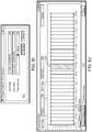
- FIG. 4is an exemplary block diagram of an asset failure detection system for performing asset failure detection in the system of FIG. 3 .
- FIG. 5illustrates various functional modules included within a failure signature recognition component.
- FIGS. 6A-6Kshow user interface screens displayed by a user interface module of an asset failure detection system.
- FIG. 7illustrates an exemplary process for performing failure signature recognition training.
- FIG. 8illustrates a failure space depicting four types of results that a failure agent may experience.
- FIGS. 9A and 9Bare collectively a process flow diagram illustrating an adaptive taxonomy-based transfer learning procedure in accordance with the present disclosure.
- FIG. 10illustrates a process for transfer learning based upon a global equipment taxonomy.
- FIGS. 11-28illustrate methods for population-based learning with deep belief networks in accordance with the present disclosure.
- the present disclosuredescribes systems and methods for improving the reliability of industrial and other equipment by substantially reducing the incidence of failure in such equipment through effectively “learning” the operational and other conditions associated with equipment failure. This enables such failure to be averted upon detection of the onset of such conditions. In one embodiment this is achieved by evaluating data from, for example, sensors associated with such equipment in order to identify patterns or relationships within the sensor data associated with equipment failure. Such patterns or relationships, which may be referred to hereinafter as “failure signatures”, may be stored within a failure signature library and made available to population of similar equipment along with baseline operating data.
- similarmay be defined in terms of a collection of hierarchical sets, each defining broader degrees of similarity, based on a central equipment taxonomy.
- the taxonomyprovides a sort of classification or “genome” for industrial equipment including information about operating context (i.e. offshore drilling rig ⁇ pump, or equipment type ⁇ centrifugal pump), make & model (i.e. Siemens SIMOTICS HV).
- operating contexti.e. offshore drilling rig ⁇ pump, or equipment type ⁇ centrifugal pump
- make & modeli.e. Siemens SIMOTICS HV
- a global taxonomy of equipment broken down by equipment type, industry, make & model, and operating contextis established.
- the taxonomymay be represented by a graph, with nodes in the graph representing sets of equipment sharing certain characteristics; that is, the taxonomy may be represented by a graph structure for defining set membership as opposed to strict hierarchy.
- This adaptive systemlearns where transfer learning applies; in other words, it empirically learns what equipment (in what context) have characteristics similar enough to support transference of signatures and operating states from other equipment. It does this empirically, by taking the global repository of signatures and testing them on new instances of the equipment class, to see if there are too many false positives (i.e., if the existing signatures apply to the new instance or not).
- all assets to be monitoredare first linked to a global equipment taxonomy. This enables each asset to be mapped to, for example, a Make-Model-Revision key, and a set of OpContext (Operating Context) keys. These keys may then be used to determine set membership for the library of known failure signatures.
- each asset to be monitoredis outfitted with a collection of sensors configured to provide data concerning operational and state characteristics of the applicable asset.
- the transfer learning techniques described hereinwill generally be most effective when member assets among which information and intelligence is to be effectively transferred are associated with similar numbers and types of sensors. However, the correspondence between the sensors associated with different assets need not be exact, and methods will be described for addressing instances in which member assets are “missing” sensors or include “extra” sensors.
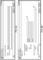
- FIG. 1Athere is shown a diagram of a conceptual system 100 intended to illustrate principles of transfer learning in accordance with the present disclosure.
- the systemincludes units of equipment, i.e., a centrifugal pump asset 110 and a centrifugal pump asset 112 comprising equipment instances to be monitored.
- a first collection of sensors 120is associated with the pump asset 110 and a second collection of sensors 122 is associated with the second pump asset 112 .
- Each of the sensors 120 and 122produces data in the form of a time series waveform indicative of some aspect of the operation or state of asset 110 or asset 112 .
- the time series waveforms 124 produced by the sensors 120 over some period of timemay define a “signature” 125 representative of the state and/or operation of the asset 110 during this time.
- time series waveforms 126 produced by the sensors 122 over some period of timemay define a signature 127 representative the state and/or operation of the asset 112 during the time period.
- a sensor template 130is defined to standardize the sensor profile of inputs for transfer learning. In the embodiment of FIG. 1A , the sensor template 130 indicates that that the “raw” data values produced by each sensor 120 and 122 specified by the template 130 should be received and processed.
- the sensor template 130may be specific to a particular make/model of the pump asset 110 and the pump asset 112 (e.g., make XYZ, model A).
- signatures 125 defined by the data collected from the sensors 120 over configurable time windows, i.e., prediction intervals,are compared with known “failure signatures” 140 maintained within a library 142 of known failure signatures in order to predict or otherwise determine when failure of the asset 110 is likely to occur.
- the library 142 of known failure signaturesmay be developed based upon sensor data collected from a large number of assets similar or identical to the assets 110 and 112 in the manner described hereinafter.
- the signatures 127 defined by the data collected from the sensors 122may be similarly compared with the known failure signatures 140 in order to predict or otherwise determine when failure of the asset 112 is likely to occur. In this way knowledge relating to potential failure scenarios is effectively transferred to the assets 110 and 112 (or to the applicable control system) through comparison of the signatures 125 , 127 developed by the sensors 120 and 122 to the known failure signatures 140 .
- FIG. 1Bdepicts a diagram of a conceptual system 100 ′ for effecting transfer learning among equipment assets in a manner similar to that described with reference to the system 100 of FIG. 1A .
- the signatures of the assets 110 and 112 being monitoredare developed not only from the time series waveforms 124 ′, 126 ′ produced by the sensors 120 and 122 , but also from derived inputs generated on the basis of such waveforms 124 ′, 126 ′.
- a first collection of derived inputs 132is generated by processing the time series waveforms 124 ′ from the sensors 120 and a second collection of derived inputs 134 is generated by processing the time series waveforms 126 ′ from sensors 122 .
- a sensor template 138identifies the raw data values produced by each sensor 120 and 122 and/or the first and second collections of derived inputs 132 and 134 that are to be received and utilized as described hereinafter.
- the sensor template 138comprises an N-dimensional sensor template linked to the make/model and operational context (OpContext) of the pump assets 110 , 112 .
- the first and second collections of derived inputs 132 and 134are calculated by applying signal processing algorithms to the streams of raw data values produced by each sensor 120 and 122 .
- signal processingmay include, for example, calculating power spectrum (frequency components extracted via Discrete Fourier Transform) for each sensor 120 and 122 ; first derivative (rate of change), and second derivative (rate of rate of change), aggregates, memory interval, and multi-resolution windows.
- power spectrumfrequency components extracted via Discrete Fourier Transform
- first derivativerate of change
- second derivativerate of rate of change
- aggregatesmay include, for example, average, maximum, minimum, and standard deviation.
- the instantaneous sample valuei.e., current sensor value
- aggregate valuesare extracted across the interval. In this way higher-resolution features are also captured. For example, in the case in which sensor values are oscillating rapidly, the standard deviation will increase and be captured as an aggregate.
- the power spectrum aggregateis calculated in the following manner. First, a Fast Fourier Transform is applied and followed by a band pass filtering operation in order to restrict frequency range.
- the elements of this arrayare then compressed into 10 (logarithmically) spaced bins; that is, the 60 samples in the time domain are reduced to 30 bins in the frequency domain, which are then summed in 10 items in logarithmic scale.
- the original quantity of datais reduced by a factor of 6.
- the following derived featuresare calculated for each tag of each sensor:
- Memory Windowincorporate window to include past sensor data along with present, exposing event sequence signatures
- Multi-Resolution Windowincorporate narrow window of high resolution data, along with wider window of low resolution data. For example, for each time step, would include a 60-second window of second data, a 24-hour window of minute data, and a 30-day window of hourly data.
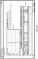
- FIG. 2Adepicts an exemplary linkage and relationship between sensor templates and equipment taxonomy.
- a sensor templateis created for a collection of equipment 210 to have one or more of the characteristics described above in order to provide structured metadata around the sensor profile for assets 212 in the collection 210 .
- functionally similar equipment assets 212 a and 212 b of differing make/modelmay be linked to the same structure and type of operational context.
- the different mud pumps 212 a and 212 bare each associated with an OpContext structure 214 of “Mud Pump” and an OpContext type 216 of “Reciprocating Pump”.
- FIG. 2Blists various types of sensor templates which could be developed for use with the collection of equipment 210 .
- the sensor templatesmay define tags for “raw” sensor data for each permutation of taxonomy and sensor configuration found in the equipment installations.
- each make/model of equipmentsupports a standard set of sensor placements. That being said, sensing devices such as vibration monitoring units (VMUs) are an exception, as each is typically acquired and installed separately from the base equipment asset being monitored.
- VMUvibration monitoring units
- a VMUmay typically be used in connection with any equipment disposed to rotate during operation.
- different sensor templatesmay be developed for each equipment units for the cases in which a VMU installed and otherwise.
- a different sensor templateis developed for each permutation of the number of channels associated with a particular sensor and, for each permutation, a separate version of the template is developed to accommodate a VMU.
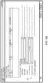
- FIG. 3illustrates a block diagram of an exemplary system 300 for performing asset failure detection using transfer learning in accordance with the disclosure.
- the system 300includes an asset failure detection system 310 , a computerized management (CM) system (also known as a computerized maintenance management system or CMMS), a first plant 320 - 1 with equipment coupled to first plant data sources 330 - 1 , a second plant 320 - 2 with equipment coupled to second plant data sources 330 - 2 , a global equipment taxonomy database server 350 and a communication network (e.g., the Internet, a WLAN, a cellular data network or other communication network) communicatively coupling the other components of the system 300 .
- CMcomputerized management
- CMMScomputerized maintenance management
- a communication networke.g., the Internet, a WLAN, a cellular data network or other communication network
- the asset failure detection system 310is configured to receive sensor data from the first and second plant data sources 330 - 1 and 330 - 2 .
- the asset failure detection systemalso receives notifications of equipment failures (e.g., work order histories, etc.) from the CM system 315 .
- the failure notifications from the CM system 315include indications of the types of failures, dates of failures, and failure codes.
- the asset failure detection system 310analyzes the sensor data received from the first and second plant data sources 330 - 1 and 330 - 2 in view of the equipment failure notifications received from the CM system 315 in order to develop learning agents to perform the failure signature recognition and anomaly detection methods described below.
- the CM system 315is similar to systems described in commonly owned and assigned U.S.
- failure signatures identified through these methodsmay be communicated to the global equipment taxonomy database server 350 for distribution to other failure detection systems associated with plant assets similar or identical to the plants 320 in order to facilitate the identification of potential failure scenarios involving such assets.
- failure signature information provided by the database server 350may be received by the asset failure detection system 310 and used during operation of the plant equipment 320 in order to identify circumstances in which the equipment 320 may be likely to fail.
- the first and second plants 320 - 1 and 320 - 2each include various plant equipment that is monitored by various sensors in the plant data sources 330 - 1 and 330 - 2 respectively.
- the first and second plant data sourceseach include a plant historian system (not shown) that stores Tag information related to sensors in the plant data sources 330 .
- the CM system 315stores data indicative of equipment hierarchy, equipment type (e.g., metadata. defining equipment type, e.g., a centrifugal pump versus a non-centrifugal pump, but no Tag information) and work order histories for the plant equipment in the plants 320 .
- equipment typee.g., metadata.
- equipment typee.g., a centrifugal pump versus a non-centrifugal pump, but no Tag information
- the asset failure detections system 310enumerates Tags from the plant historian and matches these to the equipment types and hierarchy stored in the CM system 315 . This enables multiple equipment of similar types to contribute to the failure history analysis performed at the asset failure detection system 310 .
- the asset failure detection system 310can be a computer server or servers.
- the asset failure detection system 310includes a condition based monitoring (CBM) subsystem 400 that includes a failure signature recognition component 410 , an anomaly detection component 420 and a known failure signature database 424 .
- CBMcondition based monitoring
- the CBM system 400is communicatively coupled to a plant data interface 440 which is in turn connected to the network 340 and to the plant data sources 330 .
- This connection to the plant data sources 330allows importation of sensor data from plant historians at the plant data sources 330 .
- the sensor datais used to train learning agents for the failure signature recognition component 410 and the anomaly detection component 420 .
- Information defining or referencing failure signatures recognized by the component 410may be stored within the known failure signature database 424 .
- the database 424may store information defining or referencing failure signatures received from the global equipment taxonomy database server 350 , such failure signatures having been derived from sensor data and/or aggregates associated with plant equipment similar or identical to the plants 320 .
- the CBM subsystem 400is also communicatively coupled to a CM system interface 430 that is connected to the network 340 and to the CM system 315 . As is described below, the CBM subsystem 400 imports work order histories from the CM system 315 to use as part of the failure agent training for the failure signature recognition component 410 and anomaly agent training for the anomaly detection component 420 .
- the failure and anomaly agentsare stored in a failure agent and anomaly agent database 415 that includes one or more types of storage medium.
- the CBM subsystem 400also manages changes in the plant equipment by monitoring the work order histories from the CM system 315 and the TAG identifiers associated with sensors of the plant data sources 330 .
- the CBM subsystem 400is made aware of new equipment installed at the plant equipment sites 320 .
- the CBM system 400communicates new tag and equipment identifiers to a vendor ID to universal ID mapper and translator 480 (referred to herein as the ID mapper 480 ) which maps vendor IDs to universal IDs and stores these mappings in an open object metadata registry 490 .
- the condition based monitoring system 400continually polls the CM system 315 and plant data sources 330 for new data, new tags and new equipment.
- the CBM subsystem 400communicates with the plant data sources 330 and the CM system 315 using the Mimosa protocol.
- the asset failure detection system 310also includes one or more central processing units (CPUs) 450 , a ROM (or Flash ROM or EEPROM) storage medium 460 for storing program code for execution by the one or more CPUs 450 to perform the processes described herein.
- a user interface module 470is configured to output graphical user interfaces to display devices and receive input from input mechanisms of computing devices using the asset failure detection system 310 .
- the user interfaceincludes a touch-sensitive display.
- the failure signature recognition component 410uses pattern recognition techniques to learn when failures are about to occur.
- the failure signature recognition componentidentifies fault conditions in the work order histories of the CM system 315 , takes the sensor data from the plant data sources and learns failure signatures based on the sensor data.
- the anomaly detection component 420is a forward looking analysis that pulls in past data and builds a multivariate model as to what is normal. For example, the anomaly detections component 420 can look at temperature and pressure time histories and identify abnormal measurements based on trained learning agents. The anomaly detection component 420 can use machine learning as one approach for training. The learning agents of the anomaly detection component are trained to identify an anomaly in the sensor data before a failure occurs. If an anomaly is detected, the affected equipment can be shut down and inspected to identify what may be causing the anomaly before a catastrophic failure occurs.
- the failure signature recognition component 410is made up of various functional modules as shown in FIG. 5 .
- the functional modules in FIG. 5are exemplary only and other embodiments can divide the functions differently.
- the functional modules of FIG. 5include an asset definition module 510 , a training set data importer 520 , a failure identification module 530 , a learning agent training module 540 and a sensor template database 550 . The functions performed by these functional modules will be described in reference to the methods described. herein.
- a process 700 for performing failure signature recognition trainingincludes the stages shown.
- the process 700begins at stage 705 where the asset definition module 510 receives an input identifying a piece of equipment for which failure signature recognition training is to begin.
- FIG. 6Ashows a user interface screen 600 displayed by the user interface module 470 which a user can indicate a name of a piece of equipment.
- the userhas input the name “mud pump” into a name field.
- the user interface 470Upon entering the name “mud pump” into the name field, the user interface 470 renders a user interface screen 605 illustrated in FIGS. 6B and 6K .
- the user interface screen 605provides the user with three options for selecting an asset: (1) selecting a single asset 606 at a location; (2) select an existing Failure Set 607 if the user wants to create an analysis against a group of assets; and (3) select none to create a standalone analysis 608 .
- the userenters an ID number identifying the specific pump at a specific location to be analyzed.
- the user interfacedisplays a user interface screen 610 as shown in FIG. 6C .
- the usercan select from a list of tags listed in a tag data store shown in the screen 610 .
- Each tagcorresponds to a sensor associated with the pump selected with the screen 605 in this example.
- a sensorcould be associated with an operating parameter of the pump such as pressure or temperature.
- the useris provided with a screen 615 shown in FIG. 6D .
- the screen 615allows the user to set outlier removal settings (minimum and maximum) to remove spurious data. If the received sensor data is outside of the minimum and maximum values input by the user, the sensor data is removed from the training data set.
- the user interface 470Upon setting all the outlier setting on the screen 615 , the user interface 470 renders a user interface screen 620 shown in FIG. 6E .
- the screen 620is used to create a sensor template for the chosen asset (the pump). Similar assets have similar sensors and can use the same template. Sensor templates are stored in the sensor template database 550 . Different assets could have a subset of the sensors listed on the sensor template. This embodiment uses similar assets to gather profile data for a population and learn from the population data.
- the sensor templateis a framework, but the user customizes the templates. One user's piece of equipment will have different sensor, potentially, than another user's similar piece of equipment. The user can customize the templates such that specific sensors are mapped to the specific tags on a specific piece of equipment.
- the user interface module 470renders the user interface screen 625 shown in FIG. 6F .
- the useris asked to input a rule to detect offline status (e.g., based on amperage or a current flow).
- the offline statuscould be an indication of a potential failure.
- the sensor datais not used for failure signature recognition or anomaly detection. This completes the identification of the equipment at stage 705 .
- the failure identification module 530retrieves maintenance histories that have been previously obtained from the CM system 315 .
- the failure identification module 530provides a screen 630 shown in FIG. 6G , via the user interface module 470 , that allows a user to identify failures from maintenance work order history for the selected asset/location, that have been previously received from the CM system 315 , from a downtime tracking system, or other 3rd party failure database or spreadsheet.
- the usercan use various filters to help pinpoint which work orders represent failures.
- Screen 630shows the failures defined for an asset. The output of this step is to identify a failure condition.
- the table 631 in the user interface screen 630includes a date to identify when failure events have occurred.
- the work orders received from the CM system 315include the date and a failure code which identifies a failure such as a bearing failure, motor failure etc.
- the work order maintenance historyis enumerated automatically.
- the heuristics 632 at the top of screen 630includes ways to allow a user to identify work orders that include certain characteristics. A user can identify failures automatically using this method, but a user can also choose failures manually.
- the usercan use the “offline status” feature to find past failures. By visualizing past offline conditions, the user can identify unplanned outages, and create a “virtual work order” in the asset failure detection system 310 to identify the failure event which was not properly documented in the CM system 315 .
- training data set importer module 520retrieves a set of training data comprising sensor data and related aggregates corresponding to all the tags identified at stage 705 that exhibit changes during the identified failures for the selected asset.
- the training datais filtered to remove outlier data, data when the asset is offline etc.
- the training set data importer module 520displays screen 635 shown in FIG. 6H which allows the user to identify a set of training data to import.
- the training datacan include data and related aggregates for any sensor that exhibits a change in condition (i.e., a change in sensor data values or related aggregates) at, or within a selected time period preceding, the time of the identified failure.
- a usercan choose to include as much data as is available, or a user can choose to leave out certain times.
- the failure interval 636 (720 hours) shown in screen 635allows a user to break the data into blocks for analysis. Once the time frame data is chosen, the user can choose to import the data to be analyzed.
- the training data set importer module 520displays a screen 640 shown in FIG. 6I which allows the user to verify the data to be imported.
- the training data set importer module 520displays a screen 645 , as shown in FIG. 6J , that shows sensor data for normal conditions both before and after a portion 646 of training data that includes the identified failure.
- the procedures at stages 705 , 710 , 715 and 720are repeated for many tags and many pieces of equipment matching the selected asset type until a large amount of data covering a long period of time for a large number of tags for each machine is obtained.
- data for all selected tags, as well as all selected failuresis imported by the training data set importer module 520 and stored in optimized format for machine learning. Data Interpolation can be used to fill in missing tag data.
- the imported datais stored with metadata to flag which intervals are failure intervals versus normal intervals.
- the time interval leading up to failure for which data is most importantis configurable based on a “prediction interval” specified for the Training Dataset (i.e. 30 days).
- the user-specified “prediction interval”is a hint to the system as to a starting point for the learning algorithm employed at stage 725 .
- the learning algorithmautomatically tunes the prediction interval by evaluating multiple interval durations, and selecting the one with the highest predictive accuracy for the past failure signatures.
- the learning agent training module 540analyzes the sensor data and related aggregates at times leading up to and during the identified failures.
- the signature of a failureis a characteristic pattern of sensor readings, changes in aggregates, oscillations, some changing variable, etc.
- one or more failure agentsare created and trained using the imported training data set.
- Machine learning techniquessuch as Resilient Back Propagation (RPROP), Logistic Regression (LR), and Support Vector machines (SVM) can all be used at stage 725 .
- RPROPcan be used for certain non-linear patterns
- LRenables ranking of tag prediction rank
- SVMenables confidence intervals for predictions.
- failure agentscan be trained for each fault. For example, one might be trained on a bearing failure, and another on a motor failure, which might have different signatures.
- the training at stage 725involves creating a failure agent that takes in the sensor data and related aggregates in the training set and, using machine learning, parameters of the failure agent are adjusted such that the failure agent successfully predicts the identified failures before the failures occur.
- the training at stage 725can use a tuning methodology to avoid certain types of failures.
- FIG. 8illustrates a failure space 800 illustrating the four types of results that a failure agent can experience. There are two types of successful predictions including a true negative 820 and a true positive 830 . There are also two types of errors, type 1 is a false positive 840 and type 2 is a false negative 810 . Type 2 errors can be catastrophic whereas type 1 errors can mean a little down time, but no loss of life.
- the Deep Water Horizon oil rig disasterwas a type 2 failure.
- the training at stage 725can be biased to avoid one type of error more than the other.
- a usercould weigh type 2 failures twice as much as type 1 failures for equipment where a false negative can be catastrophic such as an oil rig.
- a usercould weigh the type 1 failures to be more important.
- the usercan configure the weightings if they do not agree with the numbers of each type of failure that occur for the training data set.
- the failure agentcan be retrained after each new failure.
- the failure agentlooks at all the sensor data brought in for each piece of equipment.
- the failure signature recognition training at stage 725can be accomplished with one sensor measurement and one failure or with hundreds of sensor measurements and hundreds of failures. Data from hundreds of pieces of equipment can help but are not necessary for adequate training at stage 725 .
- the transfer learning techniques described hereincan be used to set default parameters for a starting point for training a new system. This saves time in developing the failure recognition agents for new systems.
- the learning agent training module 540can use a failure agent that was trained for old equipment with more sensors than a new pump. In other words, the new pump has a subset of the sensors for an old type of pump. One can put flat line measurements for new sensors into an old agent and retrain the old agent by importing the new sensor data. For example, if you have a failure agent trained for two sensors and you add a new sensor, the learning agent training module 540 can retrain the old failure agent based on the new sensor data using flat lined past history for the new sensor. In other words, the learning agent training module 540 starts with the signature from the prior pump and recalibrates the old failure agent using the old signature and the new sensor data.
- the process 700continues at stage 730 where the learning agent training module stores the failure agent in the failure/anomaly agent database 415 .
- the process 700is exemplary only and modifications to the process can be made without departing from the scope of the methods described herein. For example, stages may be omitted, added or rearranged.
- the transfer learning techniques described hereinare performed with respect to collections of equipment linked to a global equipment taxonomy maintained within database server 350 .
- a processwill check if the signature can be transferred to other “similar” assets, at different levels of the taxonomical hierarchy.
- centrifugal pumpassociated with 10 tags linked to the equipment taxonomy for: a) Eq Type: centrifugal pumps, b) make-model: Triplex Mud Pump BK-1600, and c) OpContext (structure)—drilling mud pump; which is linked to the appropriate sensor template (10 tags and derived features, i.e., aggregates).
- a service performsmay perform this check automatically by first trying to propagate the failure signature to pumps identical or very similar to Pump A; that is, by attempting to propagate the signature throughout the lowest level of the taxonomy (most restrictive set membership). For example, the lowest level of the taxonomy could correspond to a set of pumps having the same sensor template structure, equipment type, make-model, and OpContext.
- FIGS. 9A and 9Bare flow diagrams illustrating an adaptive taxonomy-based transfer learning procedure that could be performed by such an automatic service.
- a new failure signatureis detected on a source asset, hereinafter referred to as Asset A (stage 902 ).
- An OpContext and Make-Model informationis then obtained for Asset A (stage 904 ).
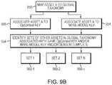
- FIG. 9Bshows during an initial installation it is assumed that Asset A has been mapped to a global equipment taxonomy (stage 950 ) and associated with a make-model key (stage 954 ) and a standard OpContext key (stage 956 ). These keys are used to perform a lookup into a global equipment library in order to identify a number of target sets 960 , where each target set is defined as follows (stage 964 ):
- stage 908member assets are determined for each target set.
- a new machine learning (“ML”) agent(or simply “Agent”) is then generated for each member asset of the collection and the normal baseline data from the target asset and the failure signature data from Asset A are acquired (stage 910 ). It is then determined whether this acquired data may be used to train a classifier to discriminate between normal and failure data (stage 912 ). For each asset, if the accuracy of the Agent for the new failure signature is sufficiently high (stage 920 ), then the asset is marked (for tracking purposes) as being linked to the failure signature (stage 922 ) and the Agent is activated for online monitoring of the target asset (stage 924 ).
- MLmachine learning
- the Agentis discarded and the asset identifier is marked as being excluded with respect to the failure signature (stage 926 ).
- the determination of whether the classifier may be configured to discriminate between data associated with normal operation and failure datainvolves comparing the sensitivity relative to the new failure signature to a configurable threshold (e.g., 75%) (stage 930 ).
- the specificity for a target Assetmay also be compared to a configurable threshold (e.g., 75%), where the failure signature from Asset A has its sensor data re-scaled based on the scaling parameters for Asset B (stage 934 ).
- an initial passis perfumed for the most restrictive class membership (identical make-model-revision and operating context), and the set membership criteria is then successively broadened to include assets higher up in the hierarchy:
- FIG. 10provides an illustration of transfer learning based on a global equipment taxonomy.
- the taxonomy lookupis based on a comprehensive database of make-model-revision information, as well as an extensible collection of operating context (OpContext) definitions maintained within the database server 350 .
- An Assetcan have multiple OpContext keys/memberships, for example a structural one (Offshore Drilling Rig ⁇ Mud Pump), and an equipment type one (reciprocating pump), a regional one (Gulf of Mexico), etc.
- a failure signature from one assetmay be combined with a normal baseline from another asset. This combined baseline and failure signature information may then be used to train a classifier to discriminate between the two. In what follows this concept is expanded to support population-based learning, which can be applied to a population of similar assets.
- a population of three centrifugal pumpsis selected. Each have the same types of sensor and make/model.
- the use of a sensor templateprovides a common “lens” through which to view each pump, as shown in FIG. 11 .
- an Equipment Setis created for the three pumps comprising the equipment in the initial target set as follows:
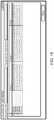
- FIG. 14illustrates an exemplary mapping. As shown, in the case of Pump 1 five tags have been mapped from a plant historian to the Sensor Roles (shown in the “Role” column) that belonging to this Sensor Template.
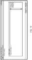
- a mapping audit report(“Equipment Set Tag Mappings”) may then be viewed to verify that, for each asset, all Sensor Roles have been mapped to a tag. As we can see in FIG. 15 , there are no gaps, indicating that everything has been appropriately mapped.
- the next steprequires definition of an “Offline Condition”.
- Thisis a Boolean logic expression, defined based on a Sensor Role, which indicates when the asset is not running (i.e. evaluates to true when the asset is offline).
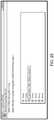
- the offline conditionis defined in terms of a Sensor Role, but when the condition is saved, the sensor role is translated to the associated tag for each asset, as shown in FIG. 17 .
- the preceding stepsrelate to creation of an Equipment Set representing a population of similar assets that is desired to be analyzed as a whole. With the Equipment Set in place, the next task is to define a machine learning DataSet based on the Equipment Set. An exemplary set of steps involved in performing this task are describe below.
- a Create DataSet Wizardis launched.
- the “Select Equipment Set” buttonis selected to create a population-based DataSet.
- this selectionresults in display of a dialog that enables selection of any of the available Equipment Sets.
- the “Centrifugal Pumps” Equipment Set defined previouslyis chosen and all the assets within that set that are desired to be included in the DataSet are selected (in this case all of the three available pumps are selected).
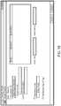
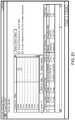
- a useris then presented with a consolidated view of the maintenance history for all three pumps. This enables the user to identify failures from the work orders. This may be done by checking the “Is Failure” column in the list. In the example of FIG. 21 , there were two failures for Pump 1.
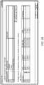
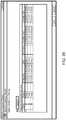
- the userselects the date range for each asset (based on how much available sensor data and maintenance data exist). In the example of FIG. 22 , the range 1/1/2010 through 8/25/2014 is selected.
- machine learning DataSetis given a name; in this example, the name
- the next stepis to import the historical data from the external plant historian into the Mtell database.
- an Agentis an instance of a neural network (or other machine learning algorithm) which has been trained on specific data with a specific set of parameters.
- the Machine Learning Wizardmay be employed to create the machine learning Agent.
- a Deep Belief Networkis used as the Agent.
- a Deep Belief Networkmay entail a network with more than three (3) layers, which incorporates unsupervised feature learning, followed by a second pass with supervised learning.
- the use of the Machine Learning Wizard to create the machine learning agentis summarized below.
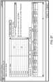
- a usermay select one or more failures. This provides the “labeled” data that is used for supervised training. Essentially, the failure work order marks a failure interval (the period of time prior to the failure), and all other intervals are considered normal intervals ( FIG. 27 ).
- the networkmay first be trained using four (4) layers of Restricted Boltzmann Machines (RBMs). Each successive layer may be trained using the output of the previous layer (the first layer uses the raw inputs from the sensor data).
- RBMsRestricted Boltzmann Machines
- the Backpropagation neural network training algorithmmay be used to fine tune the weights. This is the step where the labeled failure is used, which tunes the feature detector weights from the RBMs for the classification task.
- FIG. 28A diagram of this process is shown in FIG. 28 , which illustrates how a single output neuron (in the top-most layer) indicates failure vs normal.
- Implementation of the techniques, blocks, steps and means described abovemay be done in various ways. For example, these techniques, blocks, steps and means may be implemented in hardware, software, or a combination thereof.
- the processing unitsmay be implemented within one or more application specific integrated circuits (ASICs), digital signal processors (DSPs), digital signal processing devices (DSPDs), programmable logic devices (PLDs), field programmable gate arrays (FPGAs), processors, controllers, micro-controllers, microprocessors, other electronic units designed to perform the functions described above, and/or a combination thereof.
- ASICsapplication specific integrated circuits
- DSPsdigital signal processors
- DSPDsdigital signal processing devices
- PLDsprogrammable logic devices
- FPGAsfield programmable gate arrays
- processorscontrollers, micro-controllers, microprocessors, other electronic units designed to perform the functions described above, and/or a combination thereof.
- the embodimentsmay be described as a process which is depicted as a flowchart, a flow diagram, a data flow diagram, a structure diagram, or a block diagram. Although a flowchart may describe the operations as a sequential process, many of the operations can be performed in parallel or concurrently. In addition, the order of the operations may be re-arranged.
- a processis terminated when its operations are completed, but could have additional steps not included in the figure.
- a processmay correspond to a method, a function, a procedure, a subroutine, a subprogram, etc. When a process corresponds to a function, its termination corresponds to a return of the function to the calling function or the main function.
- embodimentsmay be implemented by hardware, software, scripting languages, firmware, middleware, microcode, hardware description languages, and/or any combination thereof.
- the program code or code segments to perform the necessary tasksmay be stored in a machine readable medium such as a storage medium.
- a code segment or machine-executable instructionmay represent a procedure, a function, a subprogram, a program, a routine, a subroutine, a module, a software package, a script, a class, or any combination of instructions, data structures, and/or program statements.
- a code segmentmay be coupled to another code segment or a hardware circuit by passing and/or receiving information, data, arguments, parameters, and/or memory contents. Information, arguments, parameters, data, etc. may be passed, forwarded, or transmitted via any suitable means including memory sharing, message passing, token passing, network transmission, etc.
- the methodologiesmay be implemented with modules (e.g., procedures, functions, and so on) that perform the functions described herein.
- Any machine-readable medium tangibly embodying instructionsmay be used in implementing the methodologies described herein.
- software codesmay be stored in a memory.
- Memorymay be implemented within the processor or external to the processor.
- the term “memory”refers to any type of long term, short term, volatile, nonvolatile, or other storage medium and is not to be limited to any particular type of memory or number of memories, or type of media upon which memory is stored.
- the term “storage medium”may represent one or more memories for storing data, including read only memory (ROM), random access memory (RAM), magnetic RAM, core memory, magnetic disk storage mediums, optical storage mediums, flash memory devices and/or other machine readable mediums for storing information.
- ROMread only memory
- RAMrandom access memory
- magnetic RAMmagnetic RAM
- core memorymagnetic disk storage mediums
- optical storage mediumsflash memory devices and/or other machine readable mediums for storing information.
- machine-readable mediumincludes, but is not limited to portable or fixed storage devices, optical storage devices, wireless channels, and/or various other storage mediums capable of storing that contain or carry instruction(s) and/or data.
- embodiments in accordance with the disclosureprovide, among other things, a system and method for automated plant asset failure detection using failure signatures or equivalent information transferred among plant sites consistent with a universal equipment taxonomy.
- Those skilled in the artcan readily recognize that numerous variations and substitutions may be made in the disclosed embodiments, their use and their configuration to achieve substantially the same results as achieved by the embodiments described herein. Accordingly, there is no intention to limit the claims to the disclosed exemplary forms. Many variations, modifications and alternative constructions fall within the scope and spirit of the disclosure.
Landscapes
- Engineering & Computer Science (AREA)
- Physics & Mathematics (AREA)
- Theoretical Computer Science (AREA)
- General Physics & Mathematics (AREA)
- Evolutionary Computation (AREA)
- Mathematical Physics (AREA)
- Artificial Intelligence (AREA)
- Software Systems (AREA)
- General Engineering & Computer Science (AREA)
- Computing Systems (AREA)
- Data Mining & Analysis (AREA)
- Automation & Control Theory (AREA)
- Medical Informatics (AREA)
- Computer Vision & Pattern Recognition (AREA)
- General Health & Medical Sciences (AREA)
- Biomedical Technology (AREA)
- Life Sciences & Earth Sciences (AREA)
- Health & Medical Sciences (AREA)
- Molecular Biology (AREA)
- Computational Linguistics (AREA)
- Biophysics (AREA)
- Testing And Monitoring For Control Systems (AREA)
Abstract
Description
- a. Frequency [10]—each bin contains intensity for that frequency band
- a. Average
- b. Minimum
- c. Maximum
- d. Standard Deviation
- Derivative (scalar)
- Second Derivative (scalar)
- Power Spectrum (vector of length 10)
- Aggregates (vector of length 4)
- Memory (vector of configurable length)
- Multi-Resolution Window (vector of configurable length)
Set 1—all other assets of same Make-Model-Rev, and OpContext Leaf node; with matching Sensor Templates (10 raw sensors of same type and sequence, with all standard derived inputs)Set 2—all other assets of same Make-Model, and OpContext Leaf node; with matching Sensor TemplatesSet 3—all other assets of same Make-Model; with matching Sensor TemplatesSet 4—all other assets of same OpContext Leaf Node; with matching Sensor Templates- Set 5—all other assets of same OpContext Leaf Node Parent; with matching Sensor Templates
- Try propagating to other revisions for the same make-model and OpContext
- Try propagating to other make-models with same OpContext
- Try propagating to other OpContexts for same make-model
- Try propagating to other OpContexts for other make-model
Claims (22)
Priority Applications (1)
| Application Number | Priority Date | Filing Date | Title |
|---|---|---|---|
| US15/721,040US10733536B2 (en) | 2013-08-26 | 2017-09-29 | Population-based learning with deep belief networks |
Applications Claiming Priority (5)
| Application Number | Priority Date | Filing Date | Title |
|---|---|---|---|
| US201361870170P | 2013-08-26 | 2013-08-26 | |
| US201462042194P | 2014-08-26 | 2014-08-26 | |
| US201414469535A | 2014-08-26 | 2014-08-26 | |
| US14/836,848US9842302B2 (en) | 2013-08-26 | 2015-08-26 | Population-based learning with deep belief networks |
| US15/721,040US10733536B2 (en) | 2013-08-26 | 2017-09-29 | Population-based learning with deep belief networks |
Related Parent Applications (1)
| Application Number | Title | Priority Date | Filing Date |
|---|---|---|---|
| US14/836,848ContinuationUS9842302B2 (en) | 2013-08-26 | 2015-08-26 | Population-based learning with deep belief networks |
Publications (2)
| Publication Number | Publication Date |
|---|---|
| US20180082217A1 US20180082217A1 (en) | 2018-03-22 |
| US10733536B2true US10733536B2 (en) | 2020-08-04 |
Family
ID=55791766
Family Applications (2)
| Application Number | Title | Priority Date | Filing Date |
|---|---|---|---|
| US14/836,848ActiveUS9842302B2 (en) | 2013-08-26 | 2015-08-26 | Population-based learning with deep belief networks |
| US15/721,040Active2035-07-13US10733536B2 (en) | 2013-08-26 | 2017-09-29 | Population-based learning with deep belief networks |
Family Applications Before (1)
| Application Number | Title | Priority Date | Filing Date |
|---|---|---|---|
| US14/836,848ActiveUS9842302B2 (en) | 2013-08-26 | 2015-08-26 | Population-based learning with deep belief networks |
Country Status (1)
| Country | Link |
|---|---|
| US (2) | US9842302B2 (en) |
Cited By (1)
| Publication number | Priority date | Publication date | Assignee | Title |
|---|---|---|---|---|
| US20220049868A1 (en)* | 2020-08-14 | 2022-02-17 | Johnson Controls Tyco IP Holdings LLP | System and method for automatic detection and clustering of variable air volume units in a building management system |
Families Citing this family (35)
| Publication number | Priority date | Publication date | Assignee | Title |
|---|---|---|---|---|
| WO2014145977A1 (en) | 2013-03-15 | 2014-09-18 | Bates Alexander B | System and methods for automated plant asset failure detection |
| US9842302B2 (en) | 2013-08-26 | 2017-12-12 | Mtelligence Corporation | Population-based learning with deep belief networks |
| US20150153251A1 (en)* | 2013-11-29 | 2015-06-04 | Johannes Izak Boerhout | Systems and methods for integrated workflow display and action panel for plant assets |
| US10657199B2 (en)* | 2016-02-25 | 2020-05-19 | Honeywell International Inc. | Calibration technique for rules used with asset monitoring in industrial process control and automation systems |
| CN107203450B (en)* | 2016-03-16 | 2020-06-02 | 伊姆西Ip控股有限责任公司 | Fault classification method and equipment |
| US11774944B2 (en) | 2016-05-09 | 2023-10-03 | Strong Force Iot Portfolio 2016, Llc | Methods and systems for the industrial internet of things |
| US11507064B2 (en) | 2016-05-09 | 2022-11-22 | Strong Force Iot Portfolio 2016, Llc | Methods and systems for industrial internet of things data collection in downstream oil and gas environment |
| US11327475B2 (en) | 2016-05-09 | 2022-05-10 | Strong Force Iot Portfolio 2016, Llc | Methods and systems for intelligent collection and analysis of vehicle data |
| US10983507B2 (en) | 2016-05-09 | 2021-04-20 | Strong Force Iot Portfolio 2016, Llc | Method for data collection and frequency analysis with self-organization functionality |
| EP3255581A1 (en)* | 2016-06-10 | 2017-12-13 | General Electric Company | Digital pattern prognostics |
| RU2714972C1 (en)* | 2016-06-14 | 2020-02-21 | Сименс Мобилити Гмбх | Prevention of malfunctions during operation of motorized door |
| US11042149B2 (en) | 2017-03-01 | 2021-06-22 | Omron Corporation | Monitoring devices, monitored control systems and methods for programming such devices and systems |
| DE102017207036A1 (en)* | 2017-04-26 | 2018-10-31 | Siemens Aktiengesellschaft | Method for computer-aided analysis of the operation of a production system |
| US10346228B2 (en)* | 2017-07-12 | 2019-07-09 | Siemens Aktiengesellschaft | Method and system for deviation detection in sensor datasets |
| US10691985B2 (en)* | 2017-09-25 | 2020-06-23 | General Electric Company | Machine learning system for in-situ recognition of common locations in a rotatable body with repeating segments |
| US11017008B2 (en)* | 2018-03-14 | 2021-05-25 | Honeywell International Inc. | Method and system for contextualizing process data |
| US10496084B2 (en)* | 2018-04-06 | 2019-12-03 | Oracle International Corporation | Dequantizing low-resolution IoT signals to produce high-accuracy prognostic indicators |
| US12248877B2 (en)* | 2018-05-23 | 2025-03-11 | Movidius Ltd. | Hybrid neural network pruning |
| EP3605119A1 (en)* | 2018-07-31 | 2020-02-05 | Siemens Aktiengesellschaft | System, apparatus and method to detect fault in an asset |
| EP3620997A1 (en)* | 2018-09-04 | 2020-03-11 | Siemens Aktiengesellschaft | Transfer learning of machine-learning models using knowledge graph database |
| EP3620996A1 (en)* | 2018-09-04 | 2020-03-11 | Siemens Aktiengesellschaft | Transfer learning of a machine-learning model using a hyperparameter response model |
| US10636484B2 (en)* | 2018-09-12 | 2020-04-28 | Winbond Electronics Corporation | Circuit and method for memory operation |
| CN109597396B (en)* | 2018-11-26 | 2019-08-23 | 国网湖北省电力有限公司电力科学研究院 | A kind of distribution transforming on-line fault diagnosis method based on high amount of traffic and transfer learning |
| WO2020173581A1 (en)* | 2019-02-27 | 2020-09-03 | Siemens Aktiengesellschaft | System, device and method of monitoring condition of a technical installation |
| CN109948550A (en)* | 2019-03-20 | 2019-06-28 | 北京百分点信息科技有限公司 | A system and method for monitoring the flow of people in a smart railway station |
| WO2020253950A1 (en)* | 2019-06-18 | 2020-12-24 | Framatome Gmbh | Monitoring method, predicting method, monitoring system and computer program |
| US11119895B2 (en)* | 2019-08-19 | 2021-09-14 | International Business Machines Corporation | Risk-focused testing |
| WO2021059227A1 (en)* | 2019-09-25 | 2021-04-01 | Single Buoy Moorings Inc. | Computer-implemented method for providing a performance parameter value being indicative of a production performance of a floating hydrocarbon production plant |
| JP7408366B2 (en)* | 2019-12-06 | 2024-01-05 | キヤノンメディカルシステムズ株式会社 | Device management device, device management system, and device management method |
| CN111982514B (en)* | 2020-08-12 | 2023-03-24 | 河北工业大学 | Bearing fault diagnosis method based on semi-supervised deep belief network |
| CN113191219B (en)* | 2021-04-15 | 2022-11-01 | 华能威宁风力发电有限公司 | Fan bearing fault self-adaptive identification method |
| US12353200B2 (en)* | 2021-07-14 | 2025-07-08 | Uptimeai Tech Private Limited | System and method for monitoring complex structures |
| CN113589797A (en)* | 2021-08-06 | 2021-11-02 | 上海应用技术大学 | Intelligent diagnosis method and system for coke oven vehicle operation fault |
| US12242260B2 (en) | 2021-10-01 | 2025-03-04 | Halliburton Energy Services, Inc. | Machine learning based equipment failure prediction |
| EP4246262B1 (en)* | 2022-03-18 | 2025-09-10 | Siemens Aktiengesellschaft | Method and device for monitoring a state of a component of a process engineering plant |
Citations (78)
| Publication number | Priority date | Publication date | Assignee | Title |
|---|---|---|---|---|
| US5764155A (en) | 1996-04-03 | 1998-06-09 | General Electric Company | Dynamic data exchange server |
| US5923834A (en) | 1996-06-17 | 1999-07-13 | Xerox Corporation | Machine dedicated monitor, predictor, and diagnostic server |
| US6192325B1 (en) | 1998-09-15 | 2001-02-20 | Csi Technology, Inc. | Method and apparatus for establishing a predictive maintenance database |
| US6266713B1 (en) | 1996-04-03 | 2001-07-24 | General Electric Company | Field upgradeable dynamic data exchanger server |
| US20010032206A1 (en) | 1999-07-09 | 2001-10-18 | Junot Systems, Inc. | External system interface method and system |
| US6421571B1 (en) | 2000-02-29 | 2002-07-16 | Bently Nevada Corporation | Industrial plant asset management system: apparatus and method |
| US20020103828A1 (en) | 2001-01-26 | 2002-08-01 | Abb Automation Inc. | System and method for world wide web based mapping of multiple system name spaces |
| US20020116486A1 (en) | 2001-02-22 | 2002-08-22 | Alcatel | Method of supervising and controlling a transport network |
| US20020161674A1 (en) | 2001-01-22 | 2002-10-31 | Scheer Robert H. | Method for fulfilling an order in an integrated supply chain management system |
| US20020183971A1 (en) | 2001-04-10 | 2002-12-05 | Wegerich Stephan W. | Diagnostic systems and methods for predictive condition monitoring |
| US20020198990A1 (en) | 2001-06-25 | 2002-12-26 | Bradfield William T. | System and method for remotely monitoring and controlling devices |
| US20030004987A1 (en) | 1996-08-23 | 2003-01-02 | Glanzer David A. | Integrated fieldbus data server architecture |
| US20030004598A1 (en) | 2001-05-31 | 2003-01-02 | Morris Martin M. | Apparatus and method for facilities maintenance management |
| US6587900B1 (en) | 2000-05-24 | 2003-07-01 | Schneider Automation, Inc. | System for communicating diagnostic data in an industrial control system |
| US20030126222A1 (en) | 2001-11-27 | 2003-07-03 | Peterson Clyde O. | Translator apparatus for two communication networks |
| US6600964B2 (en) | 1998-11-18 | 2003-07-29 | Siemens Aktiengesellschaft | Method for controlling technical processes |
| US20030200060A1 (en) | 2002-04-22 | 2003-10-23 | Evren Eryurek | On-line rotating equipment monitoring device |
| US20030200130A1 (en) | 2002-02-06 | 2003-10-23 | Kall Jonathan J. | Suite of configurable supply chain infrastructure modules for deploying collaborative e-manufacturing solutions |
| US6687761B1 (en) | 1997-02-20 | 2004-02-03 | Invensys Systems, Inc. | Process control methods and apparatus with distributed object management |
| US20040024572A1 (en) | 2002-07-31 | 2004-02-05 | Pagnano Marco Aurelio De Oliveira | System and method for monitoring devices and components |
| US20040143628A1 (en) | 2001-04-20 | 2004-07-22 | Bradford Jonathan D. | Systems and methods that discover and configure non-TCP/IP networks and devices residing therein |
| US20040153594A1 (en) | 2003-01-30 | 2004-08-05 | Rotvold Eric D. | Interface module for use with a Modbus device network and a Fieldbus device network |
| US6813587B2 (en) | 2001-06-22 | 2004-11-02 | Invensys Systems, Inc. | Remotely monitoring/diagnosing distributed components of a supervisory process control and manufacturing information application from a central location |
| US20050010931A1 (en) | 2001-12-12 | 2005-01-13 | Dirk Langkafel | System and method for communicating between software applications, particularly mes (manufacturing execution system) applications |
| US20050027379A1 (en) | 2003-08-01 | 2005-02-03 | Dyk Paul J. Van | System and method for continuous online safety and reliability monitoring |
| US20050044532A1 (en) | 2001-12-12 | 2005-02-24 | Gotthard Pfander | System and method for testing and/or debugging runtime sytems for solving mes manufacturing execution system problems |
| US20050083196A1 (en) | 2003-08-26 | 2005-04-21 | Ken Furem | System and method for remotely obtaining and managing machine data |
| US20050143956A1 (en) | 2003-10-17 | 2005-06-30 | Long Wayne R. | Equipment component monitoring and replacement management system |
| US20050177533A1 (en) | 2002-01-11 | 2005-08-11 | Michael Herzog | Method for maintaining a production installation |
| US20050267882A1 (en) | 2004-06-01 | 2005-12-01 | Eric Aupperlee | Model for communication between manufacturing and enterprise levels |
| US6993576B1 (en) | 2000-06-13 | 2006-01-31 | Onmyteam.Com, Inc. | System and method for managing maintenance of building facilities |
| US20060058987A1 (en) | 2004-09-01 | 2006-03-16 | Microsoft Corporation | Architecture, programming model and API'S |
| US20060074498A1 (en) | 2004-09-30 | 2006-04-06 | Rockwell Automation Technologies, Inc. | Enabling object oriented capabilities in automation systems |
| US20060133412A1 (en) | 2004-12-22 | 2006-06-22 | Rockwell Automation Technologies, Inc. | Integration of control and business applications using integration servers |
| US7082379B1 (en) | 2002-03-08 | 2006-07-25 | Intellectual Assets Llc | Surveillance system and method having an adaptive sequential probability fault detection test |
| US20060164296A1 (en) | 2005-01-24 | 2006-07-27 | Daniel Measurement And Control, Inc. | Method and system of determining a hierarchical structure |
| US7085841B2 (en) | 2001-07-13 | 2006-08-01 | Rockwell Automation Technologies, Inc. | Industrial controller interface providing standardized object access |
| US20060229848A1 (en) | 2005-04-08 | 2006-10-12 | Stephen Armstrong | Method and apparatus for monitoring and performing corrective measures in a process plant using monitoring data with corrective measures data |
| US7133727B2 (en) | 2003-08-01 | 2006-11-07 | Invensys Systems, Inc. | System and method for continuous online safety and reliability monitoring |
| US20060259603A1 (en) | 2005-05-16 | 2006-11-16 | Shrader Anthony G | User based - workflow and business process management |
| US7151966B1 (en) | 2002-06-04 | 2006-12-19 | Rockwell Automation Technologies, Inc. | System and methodology providing open interface and distributed processing in an industrial controller environment |
| US20070013232A1 (en) | 2002-04-02 | 2007-01-18 | Mcnally Christopher W | Method, System, and Computer Software Code for Detection and Isolation of Electrical Ground Failure and Secondary Failure |
| US7181493B2 (en) | 2003-12-23 | 2007-02-20 | Unisys Corporation | Platform independent model-based framework for exchanging information in the justice system |
| US20070143162A1 (en) | 2005-11-15 | 2007-06-21 | Ils Technology Llc | RFID with two tier connectivity, RFID in the PLC rack, secure RFID tags and RFID multiplexer system |
| US20070139211A1 (en) | 2005-12-20 | 2007-06-21 | Jean-Louis Pessin | Sensor system for a positive displacement pump |
| US20070226317A1 (en) | 2006-02-21 | 2007-09-27 | Rydberg Kris M | System, method, and device for communicating between a field device, device controller, and enterprise application |
| US20070226551A1 (en) | 2006-01-13 | 2007-09-27 | Infineon Technologies Ag | Apparatus and method for checking an error recognition functionality of a memory circuit |
| US20080079560A1 (en) | 2006-09-29 | 2008-04-03 | Rockwell Automation Technologies, Inc. | Subscribing to alarms and events in a hierarchy |
| US20080271057A1 (en) | 2007-04-26 | 2008-10-30 | Mtelligence Corporation | System and methods for the universal integration of plant floor assets and a computerized management system |
| US20090037772A1 (en)* | 2007-08-03 | 2009-02-05 | Wegerich Stephan W | Fuzzy classification approach to fault pattern matching |
| US7509537B1 (en) | 2006-02-02 | 2009-03-24 | Rockwell Collins, Inc. | Prognostic processor system for real-time failure analysis of line replaceable units |
| US7512906B1 (en) | 2002-06-04 | 2009-03-31 | Rockwell Automation Technologies, Inc. | System and methodology providing adaptive interface in an industrial controller environment |
| US20090125755A1 (en) | 2005-07-14 | 2009-05-14 | Gryphonet Ltd. | System and method for detection and recovery of malfunction in mobile devices |
| US7539724B1 (en) | 2002-06-04 | 2009-05-26 | Rockwell Automation Technologies, Inc. | Instant messaging for event notification and exchanging data in an industrial controller environment |
| US7606919B2 (en) | 2006-01-26 | 2009-10-20 | Tangopoint, Inc. | System and method for managing maintenance of building facilities |
| US20100083049A1 (en) | 2008-09-29 | 2010-04-01 | Hitachi, Ltd. | Computer system, method of detecting symptom of failure in computer system, and program |
| US20100082130A1 (en) | 2008-09-30 | 2010-04-01 | Rockwell Automation Technologies, Inc. | Modular object publication and discovery |
| US20100101785A1 (en) | 2008-10-28 | 2010-04-29 | Evgeny Khvoshchev | Hydraulic System and Method of Monitoring |
| US20100152878A1 (en) | 2008-12-16 | 2010-06-17 | Industrial Technology Research Institute | System for maintaining and analyzing manufacturing equipment and method thereof |
| US20100256794A1 (en) | 2009-04-01 | 2010-10-07 | Honeywell International Inc. | Cloud computing for a manufacturing execution system |
| US20110033122A1 (en) | 2009-08-04 | 2011-02-10 | Microsoft Corporation | Image Processing Using Masked Restricted Boltzmann Machines |
| US20110224947A1 (en) | 2010-03-15 | 2011-09-15 | Klatu Networks | Systems and methods for monitoring, inferring state of health, and optimizing efficiency of refrigeration systems |
| US8145444B1 (en) | 2007-11-30 | 2012-03-27 | Intellectual Assets Llc | Asset surveillance system and method comprising self-calibrating fault detection |
| US20120078403A1 (en) | 2005-09-22 | 2012-03-29 | Fisher-Rosemount Systems, Inc. | Use of a really simple syndication communication format in a process control system |
| US8200620B2 (en) | 2008-02-25 | 2012-06-12 | International Business Machines Corporation | Managing service processes |
| US20120173671A1 (en) | 2005-09-12 | 2012-07-05 | Rockwell Automation Technologies, Inc. | Network communications in an industrial automation environment |
| US20120283963A1 (en) | 2011-05-05 | 2012-11-08 | Mitchell David J | Method for predicting a remaining useful life of an engine and components thereof |
| US20130030765A1 (en) | 2011-07-27 | 2013-01-31 | Danni David | System and method for use in monitoring machines |
| JP2013058222A (en) | 2005-09-30 | 2013-03-28 | Rosemount Inc | Entity monitoring method, process control system and display system |
| US20130191681A1 (en) | 2010-10-11 | 2013-07-25 | General Electric Company | Systems, methods, and apparatus for signal processing-based fault detection, isolation and remediation |
| US20130226492A1 (en) | 2010-10-11 | 2013-08-29 | General Electric Company | Systems, methods, and apparatus for detecting and removing sensor signal impulse disturbances |
| US20130268241A1 (en) | 2012-04-10 | 2013-10-10 | Lockheed Martin Corporation | Efficient health management, diagnosis and prognosis of a machine |
| US20140088893A1 (en) | 2012-09-27 | 2014-03-27 | Rosemount Inc. | Hybrid power module with fault detection |
| US20140188777A1 (en) | 2012-12-27 | 2014-07-03 | General Electric Company | Methods and systems for identifying a precursor to a failure of a component in a physical system |
| US8825567B2 (en) | 2012-02-08 | 2014-09-02 | General Electric Company | Fault prediction of monitored assets |
| WO2014145977A1 (en) | 2013-03-15 | 2014-09-18 | Bates Alexander B | System and methods for automated plant asset failure detection |
| WO2016033247A2 (en) | 2014-08-26 | 2016-03-03 | Mtelligence Corporation | Population-based learning with deep belief networks |
| US20160116378A1 (en) | 2013-08-26 | 2016-04-28 | Mtelligence Corporation | Population-based learning with deep belief networks |
- 2015
- 2015-08-26USUS14/836,848patent/US9842302B2/enactiveActive
- 2017
- 2017-09-29USUS15/721,040patent/US10733536B2/enactiveActive
Patent Citations (104)
| Publication number | Priority date | Publication date | Assignee | Title |
|---|---|---|---|---|
| US6266713B1 (en) | 1996-04-03 | 2001-07-24 | General Electric Company | Field upgradeable dynamic data exchanger server |
| US5764155A (en) | 1996-04-03 | 1998-06-09 | General Electric Company | Dynamic data exchange server |
| US5923834A (en) | 1996-06-17 | 1999-07-13 | Xerox Corporation | Machine dedicated monitor, predictor, and diagnostic server |
| US20030004987A1 (en) | 1996-08-23 | 2003-01-02 | Glanzer David A. | Integrated fieldbus data server architecture |
| US7146230B2 (en) | 1996-08-23 | 2006-12-05 | Fieldbus Foundation | Integrated fieldbus data server architecture |
| US6687761B1 (en) | 1997-02-20 | 2004-02-03 | Invensys Systems, Inc. | Process control methods and apparatus with distributed object management |
| US6192325B1 (en) | 1998-09-15 | 2001-02-20 | Csi Technology, Inc. | Method and apparatus for establishing a predictive maintenance database |
| US20010001851A1 (en) | 1998-09-15 | 2001-05-24 | Piety Kenneth R. | Database wizard |
| US6600964B2 (en) | 1998-11-18 | 2003-07-29 | Siemens Aktiengesellschaft | Method for controlling technical processes |
| US20010032206A1 (en) | 1999-07-09 | 2001-10-18 | Junot Systems, Inc. | External system interface method and system |
| US20010032202A1 (en) | 1999-07-09 | 2001-10-18 | Junot Systems, Inc. | External system interface method and system |
| US6411963B1 (en) | 1999-07-09 | 2002-06-25 | Junot Systems, Inc. | External system interface method and system |
| US6466934B2 (en) | 1999-07-09 | 2002-10-15 | Junot Systems, Inc. | External system interface method and system |
| US6513044B2 (en) | 1999-07-09 | 2003-01-28 | Junot Systems, Inc. | External system interface method and system |
| US6775576B2 (en) | 2000-02-29 | 2004-08-10 | Bently Nevada, Llc | Industrial plant asset management system: apparatus and method |
| US6889096B2 (en) | 2000-02-29 | 2005-05-03 | Bently Nevada, Llc | Industrial plant asset management system: apparatus and method |
| US20030023518A1 (en) | 2000-02-29 | 2003-01-30 | Bob Spriggs | Industrial plant asset management system: apparatus and method |
| US20030028269A1 (en) | 2000-02-29 | 2003-02-06 | Bob Spriggs | Industrial plant asset management system: apparatus and method |
| US6421571B1 (en) | 2000-02-29 | 2002-07-16 | Bently Nevada Corporation | Industrial plant asset management system: apparatus and method |
| US6587900B1 (en) | 2000-05-24 | 2003-07-01 | Schneider Automation, Inc. | System for communicating diagnostic data in an industrial control system |
| US7548970B2 (en) | 2000-06-13 | 2009-06-16 | Tangopoint, Inc. | System and method for managing maintenance of building facilities |
| US6993576B1 (en) | 2000-06-13 | 2006-01-31 | Onmyteam.Com, Inc. | System and method for managing maintenance of building facilities |
| US20020161674A1 (en) | 2001-01-22 | 2002-10-31 | Scheer Robert H. | Method for fulfilling an order in an integrated supply chain management system |
| US20020103828A1 (en) | 2001-01-26 | 2002-08-01 | Abb Automation Inc. | System and method for world wide web based mapping of multiple system name spaces |
| US20020116486A1 (en) | 2001-02-22 | 2002-08-22 | Alcatel | Method of supervising and controlling a transport network |
| US20020183971A1 (en) | 2001-04-10 | 2002-12-05 | Wegerich Stephan W. | Diagnostic systems and methods for predictive condition monitoring |
| US20040143628A1 (en) | 2001-04-20 | 2004-07-22 | Bradford Jonathan D. | Systems and methods that discover and configure non-TCP/IP networks and devices residing therein |
| US20030004598A1 (en) | 2001-05-31 | 2003-01-02 | Morris Martin M. | Apparatus and method for facilities maintenance management |
| US20060224361A1 (en) | 2001-06-22 | 2006-10-05 | Invensys Systems, Inc. | Remotely monitoring/diagnosing distributed components of a supervisory process control and manufacturing information application from a central location |
| US6813587B2 (en) | 2001-06-22 | 2004-11-02 | Invensys Systems, Inc. | Remotely monitoring/diagnosing distributed components of a supervisory process control and manufacturing information application from a central location |
| US20050060408A1 (en) | 2001-06-22 | 2005-03-17 | Invensys Systems, Inc. | Remotely monitoring/diagnosing distributed components of a supervisory process control and manufacturing information application from a central location |
| US7120558B2 (en) | 2001-06-22 | 2006-10-10 | Invensys Systems, Inc. | Remotely monitoring/diagnosing distributed components of a supervisory process control and manufacturing information application from a central location |
| US20020198990A1 (en) | 2001-06-25 | 2002-12-26 | Bradfield William T. | System and method for remotely monitoring and controlling devices |
| US7085841B2 (en) | 2001-07-13 | 2006-08-01 | Rockwell Automation Technologies, Inc. | Industrial controller interface providing standardized object access |
| US20060235951A1 (en) | 2001-07-13 | 2006-10-19 | Rockwell Automation Technologies, Inc. | Industrial controller interface providing standardized object access |
| US20030126222A1 (en) | 2001-11-27 | 2003-07-03 | Peterson Clyde O. | Translator apparatus for two communication networks |
| US6901432B2 (en) | 2001-11-27 | 2005-05-31 | Eaton Corporation | Translator apparatus for two communication networks |
| US20050010931A1 (en) | 2001-12-12 | 2005-01-13 | Dirk Langkafel | System and method for communicating between software applications, particularly mes (manufacturing execution system) applications |
| US20050044532A1 (en) | 2001-12-12 | 2005-02-24 | Gotthard Pfander | System and method for testing and/or debugging runtime sytems for solving mes manufacturing execution system problems |
| US20050177533A1 (en) | 2002-01-11 | 2005-08-11 | Michael Herzog | Method for maintaining a production installation |
| US20030200130A1 (en) | 2002-02-06 | 2003-10-23 | Kall Jonathan J. | Suite of configurable supply chain infrastructure modules for deploying collaborative e-manufacturing solutions |
| US7082379B1 (en) | 2002-03-08 | 2006-07-25 | Intellectual Assets Llc | Surveillance system and method having an adaptive sequential probability fault detection test |
| US20070013232A1 (en) | 2002-04-02 | 2007-01-18 | Mcnally Christopher W | Method, System, and Computer Software Code for Detection and Isolation of Electrical Ground Failure and Secondary Failure |
| US20030200060A1 (en) | 2002-04-22 | 2003-10-23 | Evren Eryurek | On-line rotating equipment monitoring device |
| US7151966B1 (en) | 2002-06-04 | 2006-12-19 | Rockwell Automation Technologies, Inc. | System and methodology providing open interface and distributed processing in an industrial controller environment |
| US7512906B1 (en) | 2002-06-04 | 2009-03-31 | Rockwell Automation Technologies, Inc. | System and methodology providing adaptive interface in an industrial controller environment |
| US7539724B1 (en) | 2002-06-04 | 2009-05-26 | Rockwell Automation Technologies, Inc. | Instant messaging for event notification and exchanging data in an industrial controller environment |
| US20040024572A1 (en) | 2002-07-31 | 2004-02-05 | Pagnano Marco Aurelio De Oliveira | System and method for monitoring devices and components |
| US20040153594A1 (en) | 2003-01-30 | 2004-08-05 | Rotvold Eric D. | Interface module for use with a Modbus device network and a Fieldbus device network |
| US7133727B2 (en) | 2003-08-01 | 2006-11-07 | Invensys Systems, Inc. | System and method for continuous online safety and reliability monitoring |
| US7117119B2 (en) | 2003-08-01 | 2006-10-03 | Invensys Systems, Inc | System and method for continuous online safety and reliability monitoring |
| US20050027379A1 (en) | 2003-08-01 | 2005-02-03 | Dyk Paul J. Van | System and method for continuous online safety and reliability monitoring |
| US20050083196A1 (en) | 2003-08-26 | 2005-04-21 | Ken Furem | System and method for remotely obtaining and managing machine data |
| US7181370B2 (en) | 2003-08-26 | 2007-02-20 | Siemens Energy & Automation, Inc. | System and method for remotely obtaining and managing machine data |
| US20050143956A1 (en) | 2003-10-17 | 2005-06-30 | Long Wayne R. | Equipment component monitoring and replacement management system |
| US7181493B2 (en) | 2003-12-23 | 2007-02-20 | Unisys Corporation | Platform independent model-based framework for exchanging information in the justice system |
| US20050267882A1 (en) | 2004-06-01 | 2005-12-01 | Eric Aupperlee | Model for communication between manufacturing and enterprise levels |
| US20060058987A1 (en) | 2004-09-01 | 2006-03-16 | Microsoft Corporation | Architecture, programming model and API'S |
| US20060074498A1 (en) | 2004-09-30 | 2006-04-06 | Rockwell Automation Technologies, Inc. | Enabling object oriented capabilities in automation systems |
| US20060133412A1 (en) | 2004-12-22 | 2006-06-22 | Rockwell Automation Technologies, Inc. | Integration of control and business applications using integration servers |
| US20060164296A1 (en) | 2005-01-24 | 2006-07-27 | Daniel Measurement And Control, Inc. | Method and system of determining a hierarchical structure |
| US8005647B2 (en) | 2005-04-08 | 2011-08-23 | Rosemount, Inc. | Method and apparatus for monitoring and performing corrective measures in a process plant using monitoring data with corrective measures data |
| US20060229848A1 (en) | 2005-04-08 | 2006-10-12 | Stephen Armstrong | Method and apparatus for monitoring and performing corrective measures in a process plant using monitoring data with corrective measures data |
| US20060259603A1 (en) | 2005-05-16 | 2006-11-16 | Shrader Anthony G | User based - workflow and business process management |
| US20090125755A1 (en) | 2005-07-14 | 2009-05-14 | Gryphonet Ltd. | System and method for detection and recovery of malfunction in mobile devices |
| US20120173671A1 (en) | 2005-09-12 | 2012-07-05 | Rockwell Automation Technologies, Inc. | Network communications in an industrial automation environment |
| US20120078403A1 (en) | 2005-09-22 | 2012-03-29 | Fisher-Rosemount Systems, Inc. | Use of a really simple syndication communication format in a process control system |
| JP2013058222A (en) | 2005-09-30 | 2013-03-28 | Rosemount Inc | Entity monitoring method, process control system and display system |
| JP2009510601A (en) | 2005-09-30 | 2009-03-12 | ローズマウント インコーポレイテッド | Method and apparatus for monitoring and corrective actions in process plants using monitoring data and corrective action data |
| US20070143162A1 (en) | 2005-11-15 | 2007-06-21 | Ils Technology Llc | RFID with two tier connectivity, RFID in the PLC rack, secure RFID tags and RFID multiplexer system |
| US20070139211A1 (en) | 2005-12-20 | 2007-06-21 | Jean-Louis Pessin | Sensor system for a positive displacement pump |
| US20070226551A1 (en) | 2006-01-13 | 2007-09-27 | Infineon Technologies Ag | Apparatus and method for checking an error recognition functionality of a memory circuit |
| US7606919B2 (en) | 2006-01-26 | 2009-10-20 | Tangopoint, Inc. | System and method for managing maintenance of building facilities |
| US7509537B1 (en) | 2006-02-02 | 2009-03-24 | Rockwell Collins, Inc. | Prognostic processor system for real-time failure analysis of line replaceable units |
| US20070226317A1 (en) | 2006-02-21 | 2007-09-27 | Rydberg Kris M | System, method, and device for communicating between a field device, device controller, and enterprise application |
| US20080079560A1 (en) | 2006-09-29 | 2008-04-03 | Rockwell Automation Technologies, Inc. | Subscribing to alarms and events in a hierarchy |
| US8380842B2 (en) | 2007-04-26 | 2013-02-19 | Mtelligence Corporation | System and methods for the universal integration of plant floor assets and a computerized management system |
| US20080271057A1 (en) | 2007-04-26 | 2008-10-30 | Mtelligence Corporation | System and methods for the universal integration of plant floor assets and a computerized management system |
| US20090037772A1 (en)* | 2007-08-03 | 2009-02-05 | Wegerich Stephan W | Fuzzy classification approach to fault pattern matching |
| US8145444B1 (en) | 2007-11-30 | 2012-03-27 | Intellectual Assets Llc | Asset surveillance system and method comprising self-calibrating fault detection |
| US8200620B2 (en) | 2008-02-25 | 2012-06-12 | International Business Machines Corporation | Managing service processes |
| US20100083049A1 (en) | 2008-09-29 | 2010-04-01 | Hitachi, Ltd. | Computer system, method of detecting symptom of failure in computer system, and program |
| US20100082130A1 (en) | 2008-09-30 | 2010-04-01 | Rockwell Automation Technologies, Inc. | Modular object publication and discovery |
| US20100101785A1 (en) | 2008-10-28 | 2010-04-29 | Evgeny Khvoshchev | Hydraulic System and Method of Monitoring |
| US20100152878A1 (en) | 2008-12-16 | 2010-06-17 | Industrial Technology Research Institute | System for maintaining and analyzing manufacturing equipment and method thereof |
| US20100256794A1 (en) | 2009-04-01 | 2010-10-07 | Honeywell International Inc. | Cloud computing for a manufacturing execution system |
| US20110033122A1 (en) | 2009-08-04 | 2011-02-10 | Microsoft Corporation | Image Processing Using Masked Restricted Boltzmann Machines |
| US20110224947A1 (en) | 2010-03-15 | 2011-09-15 | Klatu Networks | Systems and methods for monitoring, inferring state of health, and optimizing efficiency of refrigeration systems |
| US20130191681A1 (en) | 2010-10-11 | 2013-07-25 | General Electric Company | Systems, methods, and apparatus for signal processing-based fault detection, isolation and remediation |
| US20130226492A1 (en) | 2010-10-11 | 2013-08-29 | General Electric Company | Systems, methods, and apparatus for detecting and removing sensor signal impulse disturbances |
| US20120283963A1 (en) | 2011-05-05 | 2012-11-08 | Mitchell David J | Method for predicting a remaining useful life of an engine and components thereof |
| US20130030765A1 (en) | 2011-07-27 | 2013-01-31 | Danni David | System and method for use in monitoring machines |
| US8825567B2 (en) | 2012-02-08 | 2014-09-02 | General Electric Company | Fault prediction of monitored assets |
| US20130268241A1 (en) | 2012-04-10 | 2013-10-10 | Lockheed Martin Corporation | Efficient health management, diagnosis and prognosis of a machine |
| US20140088893A1 (en) | 2012-09-27 | 2014-03-27 | Rosemount Inc. | Hybrid power module with fault detection |
| US20140188777A1 (en) | 2012-12-27 | 2014-07-03 | General Electric Company | Methods and systems for identifying a precursor to a failure of a component in a physical system |
| WO2014145977A1 (en) | 2013-03-15 | 2014-09-18 | Bates Alexander B | System and methods for automated plant asset failure detection |
| US20140351642A1 (en) | 2013-03-15 | 2014-11-27 | Mtelligence Corporation | System and methods for automated plant asset failure detection |
| US9535808B2 (en) | 2013-03-15 | 2017-01-03 | Mtelligence Corporation | System and methods for automated plant asset failure detection |
| US20170083830A1 (en) | 2013-03-15 | 2017-03-23 | Mtelligence Corporation | System and Methods for Automated Plant Asset Failure Detection |
| US10192170B2 (en) | 2013-03-15 | 2019-01-29 | Mtelligence Corporation | System and methods for automated plant asset failure detection |
| US20160116378A1 (en) | 2013-08-26 | 2016-04-28 | Mtelligence Corporation | Population-based learning with deep belief networks |
| US9842302B2 (en) | 2013-08-26 | 2017-12-12 | Mtelligence Corporation | Population-based learning with deep belief networks |
| WO2016033247A2 (en) | 2014-08-26 | 2016-03-03 | Mtelligence Corporation | Population-based learning with deep belief networks |
Non-Patent Citations (11)
| Title |
|---|
| Extended European Search Report for European Application No. 15835656.8, "Population Based Learning With Deep Belief Networks", dated Sep. 29, 2017 (8 pages). |
| Fischer, A. et al., "An Introduction to Restricted Boltzmann Machines," LNCS, 7441: 14-36 (2012). |
| Hinton, G., "A Practical Guide to Training Restricted Boltzmann Machines," Department of Computer Science, University of Toronto, pp. 1-21 (Aug. 2, 2010). |
| International Preliminary Report on Patentability for Int'l Application No. PCT/US2014/030840, titled: System and Methods for Automated Plant Asset Failure Detection, dated Sep. 15, 2015 (12 pages). |
| International Preliminary Report on Patentability for Int'l Application No. PCT/US2015/047047, titled: Population-Based Learning With Deep Belief Networks, dated Feb. 28, 2017 (4 pages). |
| International Search Report for Intl Application No. PCT/US2014/030840, titled: System and Methods for Automated Plant Asset Failure Detection, dated Aug. 26, 2014 (3 pages). |
| International Search Report for Int'l Application No. PCT/US2015/047047, titled: Population-Based Learning With Deep Belief Networks, dated Mar. 18, 2016 (3 pages). |
| Pardhan et al., "Deep Learning using Restricted Boltzmann machines," international Journal on Advanced Computer Theory and Engineering, 4(3): 10-15 (2015). |
| Written Opinion for Int'l Application No. PCT/US2014/030840, titled: System and Methods for Automated Plant Asset Failure Detection, dated Aug. 26, 2014 (3 pages). |
| Written Opinion for Int'l Application No. PCT/US2015/047047, titled: Population-Based Learning With Deep Belief Networks, dated Mar. 18, 2016 (3 pages). |
| Zhang et al., "Degradation Prediction Model Based on a Neural Network with Dynamic Windows," ISSN, 1424-8220: 6996-7015 (Mar. 23, 2015). |
Cited By (2)
| Publication number | Priority date | Publication date | Assignee | Title |
|---|---|---|---|---|
| US20220049868A1 (en)* | 2020-08-14 | 2022-02-17 | Johnson Controls Tyco IP Holdings LLP | System and method for automatic detection and clustering of variable air volume units in a building management system |
| US12435893B2 (en)* | 2020-08-14 | 2025-10-07 | Tyco Fire & Security Gmbh | System and method for automatic detection and clustering of variable air volume units in a building management system |
Also Published As
| Publication number | Publication date |
|---|---|
| US20180082217A1 (en) | 2018-03-22 |
| US9842302B2 (en) | 2017-12-12 |
| US20160116378A1 (en) | 2016-04-28 |
Similar Documents
| Publication | Publication Date | Title |
|---|---|---|
| US10733536B2 (en) | Population-based learning with deep belief networks | |
| EP3183622B1 (en) | Population-based learning with deep belief networks | |
| US10192170B2 (en) | System and methods for automated plant asset failure detection | |
| US10777470B2 (en) | Selective inclusion/exclusion of semiconductor chips in accelerated failure tests | |
| US20230112083A1 (en) | Computer System and Method for Creating an Event Prediction Model | |
| US20190392098A1 (en) | Learning Expected Operational Behavior Of Machines From Generic Definitions And Past Behavior | |
| US12181866B2 (en) | Systems and methods for predicting manufacturing process risks | |
| JP6875179B2 (en) | System analyzer and system analysis method | |
| EP3827387A1 (en) | Systematic prognostic analysis with dynamic causal model | |
| US20100100521A1 (en) | Diagnostic system | |
| Alauddin et al. | A robust neural network model for fault detection in the presence of mislabelled data | |
| CN111061581A (en) | Fault detection method, device and equipment | |
| Mendia et al. | A novel approach for the detection of anomalous energy consumption patterns in industrial cyber‐physical systems | |
| Sharma et al. | An Insight Survey on Sensor Errors and Fault Detection Techniques in Smart Spaces. | |
| JP2025529889A (en) | Real-time detection, prediction, and repair of machine learning model drift in asset hierarchies based on time-series data | |
| Kånåhols et al. | Integrating Time Series Anomaly Detection Into DevOps Workflows | |
| WO2024063787A1 (en) | Asset structure behavior learning and inference management system | |
| JP7347547B2 (en) | Event analysis support device, event analysis support method, and program | |
| Suryanarayana | Safety of AI Systems for Prognostics and Health Management | |
| Vailraj | AI-Assisted Incident Management in SRE: The Role of LLMs and Anomaly Detection | |
| Zabadi et al. | Integration of Digital Twins and Machine Learning for Predictive Maintenance Using APAR Method Rules in Non-residential Buildings | |
| Toothman | Adaptive, State-Based Modeling Applied to Prognostics and Health Management of Industrial Rotating Equipment | |
| Munger | The Development of Representation-Based Methods for Knowledge Engineering of Computer Networks | |
| Lunde et al. | Multi-disciplinary, multi-user process monitoring: Cross-discipline development and cross-company collaboration | |
| Heda | Case Study in Improving the Health of a Remote Monitoring & Diagnostics Center |
Legal Events
| Date | Code | Title | Description |
|---|---|---|---|
| FEPP | Fee payment procedure | Free format text:ENTITY STATUS SET TO UNDISCOUNTED (ORIGINAL EVENT CODE: BIG.); ENTITY STATUS OF PATENT OWNER: LARGE ENTITY | |
| AS | Assignment | Owner name:MTELLIGENCE CORPORATION, CALIFORNIA Free format text:ASSIGNMENT OF ASSIGNORS INTEREST;ASSIGNORS:BATES, ALEXANDER B.;KIM, CAROLINE;RAHILLY, PAUL;SIGNING DATES FROM 20170502 TO 20170623;REEL/FRAME:043824/0755 | |
| STPP | Information on status: patent application and granting procedure in general | Free format text:DOCKETED NEW CASE - READY FOR EXAMINATION | |
| STPP | Information on status: patent application and granting procedure in general | Free format text:NON FINAL ACTION MAILED | |
| STPP | Information on status: patent application and granting procedure in general | Free format text:RESPONSE TO NON-FINAL OFFICE ACTION ENTERED AND FORWARDED TO EXAMINER | |
| STPP | Information on status: patent application and granting procedure in general | Free format text:NOTICE OF ALLOWANCE MAILED -- APPLICATION RECEIVED IN OFFICE OF PUBLICATIONS | |
| STPP | Information on status: patent application and granting procedure in general | Free format text:PUBLICATIONS -- ISSUE FEE PAYMENT VERIFIED | |
| STCF | Information on status: patent grant | Free format text:PATENTED CASE | |
| CC | Certificate of correction | ||
| AS | Assignment | Owner name:ASPEN TECHNOLOGY, INC., MASSACHUSETTS Free format text:ASSIGNMENT OF ASSIGNORS INTEREST;ASSIGNOR:MTELLIGENCE CORPORATION;REEL/FRAME:058976/0628 Effective date:20220209 | |
| AS | Assignment | Owner name:ASPENTECH CORPORATION, MASSACHUSETTS Free format text:CHANGE OF NAME;ASSIGNOR:ASPEN TECHNOLOGY, INC.;REEL/FRAME:061006/0171 Effective date:20220516 | |
| AS | Assignment | Owner name:JPMORGAN CHASE BANK, N.A., AS ADMINISTRATIVE AGENT, ILLINOIS Free format text:SECURITY INTEREST;ASSIGNORS:ASPENTECH CORPORATION F/K/A ASPEN TECHNOLOGY, INC.;EMERSON PARADIGM HOLDINGS LLC;PARADIGM GEOPHYSICAL CORP.;AND OTHERS;REEL/FRAME:061161/0782 Effective date:20220516 | |
| MAFP | Maintenance fee payment | Free format text:PAYMENT OF MAINTENANCE FEE, 4TH YEAR, LARGE ENTITY (ORIGINAL EVENT CODE: M1551); ENTITY STATUS OF PATENT OWNER: LARGE ENTITY Year of fee payment:4 | |
| AS | Assignment | Owner name:JPMORGAN CHASE BANK, N.A., AS ADMINISTRATIVE AGENT, ILLINOIS Free format text:SECURITY INTEREST;ASSIGNORS:ASPENTECH CORPORATION;ASPEN PARADIGM HOLDING LLC;REEL/FRAME:068424/0341 Effective date:20240627 |