US10731559B2 - Lubrication system for gas turbine engines - Google Patents
Lubrication system for gas turbine enginesDownload PDFInfo
- Publication number
- US10731559B2 US10731559B2US15/875,179US201815875179AUS10731559B2US 10731559 B2US10731559 B2US 10731559B2US 201815875179 AUS201815875179 AUS 201815875179AUS 10731559 B2US10731559 B2US 10731559B2
- Authority
- US
- United States
- Prior art keywords
- engine
- gas turbine
- lubricant
- condition
- turbine engine
- Prior art date
- Legal status (The legal status is an assumption and is not a legal conclusion. Google has not performed a legal analysis and makes no representation as to the accuracy of the status listed.)
- Active, expires
Links
Images


Classifications
- F—MECHANICAL ENGINEERING; LIGHTING; HEATING; WEAPONS; BLASTING
- F02—COMBUSTION ENGINES; HOT-GAS OR COMBUSTION-PRODUCT ENGINE PLANTS
- F02C—GAS-TURBINE PLANTS; AIR INTAKES FOR JET-PROPULSION PLANTS; CONTROLLING FUEL SUPPLY IN AIR-BREATHING JET-PROPULSION PLANTS
- F02C7/00—Features, components parts, details or accessories, not provided for in, or of interest apart form groups F02C1/00 - F02C6/00; Air intakes for jet-propulsion plants
- F02C7/06—Arrangements of bearings; Lubricating
- F—MECHANICAL ENGINEERING; LIGHTING; HEATING; WEAPONS; BLASTING
- F01—MACHINES OR ENGINES IN GENERAL; ENGINE PLANTS IN GENERAL; STEAM ENGINES
- F01D—NON-POSITIVE DISPLACEMENT MACHINES OR ENGINES, e.g. STEAM TURBINES
- F01D25/00—Component parts, details, or accessories, not provided for in, or of interest apart from, other groups
- F01D25/18—Lubricating arrangements
- F01D25/20—Lubricating arrangements using lubrication pumps
- F—MECHANICAL ENGINEERING; LIGHTING; HEATING; WEAPONS; BLASTING
- F01—MACHINES OR ENGINES IN GENERAL; ENGINE PLANTS IN GENERAL; STEAM ENGINES
- F01M—LUBRICATING OF MACHINES OR ENGINES IN GENERAL; LUBRICATING INTERNAL COMBUSTION ENGINES; CRANKCASE VENTILATING
- F01M1/00—Pressure lubrication
- F01M1/16—Controlling lubricant pressure or quantity
- F—MECHANICAL ENGINEERING; LIGHTING; HEATING; WEAPONS; BLASTING
- F02—COMBUSTION ENGINES; HOT-GAS OR COMBUSTION-PRODUCT ENGINE PLANTS
- F02C—GAS-TURBINE PLANTS; AIR INTAKES FOR JET-PROPULSION PLANTS; CONTROLLING FUEL SUPPLY IN AIR-BREATHING JET-PROPULSION PLANTS
- F02C3/00—Gas-turbine plants characterised by the use of combustion products as the working fluid
- F02C3/04—Gas-turbine plants characterised by the use of combustion products as the working fluid having a turbine driving a compressor
- F02C3/107—Gas-turbine plants characterised by the use of combustion products as the working fluid having a turbine driving a compressor with two or more rotors connected by power transmission
- F—MECHANICAL ENGINEERING; LIGHTING; HEATING; WEAPONS; BLASTING
- F02—COMBUSTION ENGINES; HOT-GAS OR COMBUSTION-PRODUCT ENGINE PLANTS
- F02C—GAS-TURBINE PLANTS; AIR INTAKES FOR JET-PROPULSION PLANTS; CONTROLLING FUEL SUPPLY IN AIR-BREATHING JET-PROPULSION PLANTS
- F02C7/00—Features, components parts, details or accessories, not provided for in, or of interest apart form groups F02C1/00 - F02C6/00; Air intakes for jet-propulsion plants
- F02C7/12—Cooling of plants
- F02C7/14—Cooling of plants of fluids in the plant, e.g. lubricant or fuel
- F—MECHANICAL ENGINEERING; LIGHTING; HEATING; WEAPONS; BLASTING
- F02—COMBUSTION ENGINES; HOT-GAS OR COMBUSTION-PRODUCT ENGINE PLANTS
- F02C—GAS-TURBINE PLANTS; AIR INTAKES FOR JET-PROPULSION PLANTS; CONTROLLING FUEL SUPPLY IN AIR-BREATHING JET-PROPULSION PLANTS
- F02C7/00—Features, components parts, details or accessories, not provided for in, or of interest apart form groups F02C1/00 - F02C6/00; Air intakes for jet-propulsion plants
- F02C7/36—Power transmission arrangements between the different shafts of the gas turbine plant, or between the gas-turbine plant and the power user
- F—MECHANICAL ENGINEERING; LIGHTING; HEATING; WEAPONS; BLASTING
- F16—ENGINEERING ELEMENTS AND UNITS; GENERAL MEASURES FOR PRODUCING AND MAINTAINING EFFECTIVE FUNCTIONING OF MACHINES OR INSTALLATIONS; THERMAL INSULATION IN GENERAL
- F16H—GEARING
- F16H57/00—General details of gearing
- F16H57/04—Features relating to lubrication or cooling or heating
- F16H57/0434—Features relating to lubrication or cooling or heating relating to lubrication supply, e.g. pumps; Pressure control
- F16H57/0435—Pressure control for supplying lubricant; Circuits or valves therefor
- F—MECHANICAL ENGINEERING; LIGHTING; HEATING; WEAPONS; BLASTING
- F01—MACHINES OR ENGINES IN GENERAL; ENGINE PLANTS IN GENERAL; STEAM ENGINES
- F01M—LUBRICATING OF MACHINES OR ENGINES IN GENERAL; LUBRICATING INTERNAL COMBUSTION ENGINES; CRANKCASE VENTILATING
- F01M13/00—Crankcase ventilating or breathing
- F01M13/04—Crankcase ventilating or breathing having means for purifying air before leaving crankcase, e.g. removing oil
- F01M2013/0472—Crankcase ventilating or breathing having means for purifying air before leaving crankcase, e.g. removing oil using heating means
- F—MECHANICAL ENGINEERING; LIGHTING; HEATING; WEAPONS; BLASTING
- F05—INDEXING SCHEMES RELATING TO ENGINES OR PUMPS IN VARIOUS SUBCLASSES OF CLASSES F01-F04
- F05D—INDEXING SCHEME FOR ASPECTS RELATING TO NON-POSITIVE-DISPLACEMENT MACHINES OR ENGINES, GAS-TURBINES OR JET-PROPULSION PLANTS
- F05D2260/00—Function
- F05D2260/50—Kinematic linkage, i.e. transmission of position
- F05D2260/53—Kinematic linkage, i.e. transmission of position using gears
- F—MECHANICAL ENGINEERING; LIGHTING; HEATING; WEAPONS; BLASTING
- F16—ENGINEERING ELEMENTS AND UNITS; GENERAL MEASURES FOR PRODUCING AND MAINTAINING EFFECTIVE FUNCTIONING OF MACHINES OR INSTALLATIONS; THERMAL INSULATION IN GENERAL
- F16N—LUBRICATING
- F16N2210/00—Applications
- F16N2210/02—Turbines
- F—MECHANICAL ENGINEERING; LIGHTING; HEATING; WEAPONS; BLASTING
- F16—ENGINEERING ELEMENTS AND UNITS; GENERAL MEASURES FOR PRODUCING AND MAINTAINING EFFECTIVE FUNCTIONING OF MACHINES OR INSTALLATIONS; THERMAL INSULATION IN GENERAL
- F16N—LUBRICATING
- F16N2250/00—Measuring
- F16N2250/08—Temperature
- Y—GENERAL TAGGING OF NEW TECHNOLOGICAL DEVELOPMENTS; GENERAL TAGGING OF CROSS-SECTIONAL TECHNOLOGIES SPANNING OVER SEVERAL SECTIONS OF THE IPC; TECHNICAL SUBJECTS COVERED BY FORMER USPC CROSS-REFERENCE ART COLLECTIONS [XRACs] AND DIGESTS
- Y02—TECHNOLOGIES OR APPLICATIONS FOR MITIGATION OR ADAPTATION AGAINST CLIMATE CHANGE
- Y02T—CLIMATE CHANGE MITIGATION TECHNOLOGIES RELATED TO TRANSPORTATION
- Y02T50/00—Aeronautics or air transport
- Y02T50/60—Efficient propulsion technologies, e.g. for aircraft
- Y02T50/671—
Definitions
- This disclosuregenerally relates to gas turbine engines and, more particularly, relates to a lubrication system for gas turbine engine components.
- gas turbine enginesfor generating energy and propulsion.
- Such enginesinclude a fan, compressor, combustor and turbine provided in serial fashion, forming an engine core and arranged along a central longitudinal axis. Air enters the gas turbine engine through the fan and is pressurized in the compressor. This pressurized air is mixed with fuel in the combustor. The fuel-air mixture is then ignited, generating hot combustion gases that flow downstream to the turbine. The turbine is driven by the exhaust gases and mechanically powers the compressor and fan via one or more central rotating shafts. Energy from the combustion gases not used by the turbine is discharged through an exhaust nozzle, producing thrust to power the aircraft.
- Turbofan gas turbine enginescontain an engine core and fan surrounded by a fan case, forming part of a nacelle.
- the nacelleis a housing that contains the engine.
- the fanis positioned forward of the engine core and within the fan case.
- the engine coreis surrounded by an engine core cowl and the area between the nacelle and the engine core cowl is functionally defined as a fan duct.
- the fan ductis substantially annular in shape to accommodate the airflow from the fan and around the engine core cowl.
- the airflow through the fan ductknown as bypass air, travels the length of the fan duct and exits at the aft end of the fan duct at an exhaust nozzle.
- the fan of gas turbine enginesIn addition to thrust generated by combustion gasses, the fan of gas turbine engines also produces thrust by accelerating and discharging ambient air through the exhaust nozzle.
- Various parts of the gas turbine enginegenerate heat while operating, including the compressor, combustor, turbine, central rotating shaft and fan. To maintain proper operational temperatures, excess heat is often removed from the engine via oil coolant loops, including air/oil or fuel/oil heat exchangers, and dumped into the bypass airflow for removal from the system.
- Gas turbine enginesrequire a supply of lubricant, such as oil, to mechanical components such as, but not limited to, bearings, seals, and the like.
- the oilcan be used as a lubricant, a coolant or both.
- Typical oil systemssupply the oil to a manifold, which then directs the oil to various engine components.
- the lubricantmay be filtered to remove unwanted debris, and may also be de-aerated to remove any air absorbed by the oil while lubricating and cooling the components.
- An oil coolermay remove heat gained from the lubricated components.
- a lubrication system for a gas turbine enginemay include a pump for moving a lubricant, a lubricant tank for storing the lubricant, an engine component requiring lubrication from the lubricant, a conduit between the lubricant tank and the engine component, and a scheduling valve positioned in the conduit between the lubricant tank and the engine component, the flow scheduling valve varying a flow of the lubricant to the engine component based on a condition.
- the engine componentmay be a fan drive gear system, and the scheduling valve may be controlled by a controller.
- the controllermay include a memory and a processor, and the memory may include an engine performance model.
- the conditionmay be a calculated engine torque, an engine startup, cruising, an altitude of the gas turbine engine, a vibration level of the gas turbine engine, or a weight on wheels.
- the present disclosurealso provides a gas turbine engine, that may include a compressor, a combustor downstream of the compressor, a lubrication system including a pump for moving a lubricant, a lubricant tank for storing the lubricant, an engine component requiring lubrication from the lubricant, a conduit between the lubricant tank and the engine component, a scheduling valve positioned in the conduit between the lubricant tank and the engine component, the flow scheduling valve varying a flow of the lubricant to the engine component based on a condition, and a turbine downstream of the combustor.
- a gas turbine enginemay include a compressor, a combustor downstream of the compressor, a lubrication system including a pump for moving a lubricant, a lubricant tank for storing the lubricant, an engine component requiring lubrication from the lubricant, a conduit between the lubricant tank and the engine component, a scheduling valve positioned in the
- the engine componentmay be a fan drive gear system, and the scheduling valve may be controlled by a controller.
- the controllermay include a memory and a processor, and the memory may include an engine performance model.
- the conditionmay be a calculated engine torque, an altitude of the gas turbine engine or a vibration level of the gas turbine engine.
- the present disclosurefurther provides a method of lubricating an engine component of a gas turbine engine that may include pumping a lubricant from a lubricant tank through a conduit to the engine component using a pump, determining a condition experienced by the gas turbine engine, and regulating a flow of the lubricant to the engine component with a scheduling valve, the regulation of the flow of lubricant based upon the condition experienced by the gas turbine engine.
- the engine componentmay be a fan drive gear system, and the scheduling valve may be controlled by a controller, wherein the controller may include a memory and a processor, and the memory may include an engine performance model.
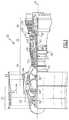
- FIG. 1is a sectional view of a gas turbine engine constructed in accordance with an embodiment.
- FIG. 2is a schematic representation of a lubrication injection system constructed in accordance with an embodiment.
- FIG. 3is a schematic representation of a controller and associated engine conditions the controller may monitor according to an embodiment.
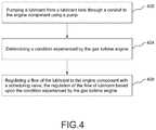
- FIG. 4is a flowchart depicting a sample sequence of actions and events which may be practiced in accordance with an embodiment.
- a gas turbine engine 20is generally referred to by reference numeral 20 .
- the gas turbine engine 20is disclosed herein as a two-spool turbofan that generally incorporates a fan section 22 , a compressor section 24 , a combustor section 26 and a turbine section 28 .
- Alternative enginesmight include an augmentor section (not shown) among other systems or features.
- the fan section 22drives air along a bypass flow path B in a bypass duct defined within a nacelle 15
- the compressor section 24drives air along a core flow path C for compression and communication into the combustor section 26 then expansion through the turbine section 28 .
- the exemplary engine 20generally includes a low speed spool 30 and a high speed spool 32 mounted for rotation about an engine central longitudinal axis A relative to an engine static structure 36 via several bearing systems 38 . It should be understood that various bearing systems 38 at various locations may alternatively or additionally be provided, and the location of bearing systems 38 may be varied as appropriate to the application.
- the low speed spool 30generally includes an inner shaft 40 that interconnects a fan 42 , a low pressure compressor 44 and a low pressure turbine 46 .
- the inner shaft 40is connected to the fan 42 through a speed change mechanism, which in exemplary gas turbine engine 20 is illustrated as a geared architecture 48 to drive the fan 42 at a lower speed than the low speed spool 30 .
- the high speed spool 32includes an outer shaft 50 that interconnects a high pressure compressor 52 and high pressure turbine 54 .
- a combustor 56is arranged in exemplary gas turbine 20 between the high pressure compressor 52 and the high pressure turbine 54 .
- a mid-turbine frame 57 of the engine static structure 36is arranged generally between the high pressure turbine 54 and the low pressure turbine 46 .
- the mid-turbine frame 57further supports bearing systems 38 in the turbine section 28 .
- the inner shaft 40 and the outer shaft 50are concentric and rotate via bearing systems 38 about the engine central longitudinal axis A which is collinear with their longitudinal axes.
- the core airflowis compressed by the low pressure compressor 44 then the high pressure compressor 52 , mixed and burned with fuel in the combustor 56 , then expanded over the high pressure turbine 54 and low pressure turbine 46 .
- the mid-turbine frame 57includes airfoils 59 which are in the core airflow path C.
- the turbines 46 , 54rotationally drive the respective low speed spool 30 and high speed spool 32 in response to the expansion.
- each of the positions of the fan section 22 , compressor section 24 , combustor section 26 , turbine section 28 , and geared architecture 48may be varied.
- geared architecture 48may be located aft of combustor section 26 or even aft of turbine section 28
- fan section 22may be positioned forward or aft of the location of geared architecture 48 .
- the gas turbine engine 20 in one exampleis a high-bypass geared aircraft engine.
- the gas turbine engine 20 bypass ratiois greater than about six (6), with an example embodiment being greater than about ten (10)
- the geared architecture 48is an epicyclic gear train, such as a planetary gear system or other gear system, with a gear reduction ratio of greater than about 2.3
- the low pressure turbine 46has a pressure ratio that is greater than about five.
- the gas turbine engine 20 bypass ratiois greater than about ten (10:1)
- the fan diameteris significantly larger than that of the low pressure compressor 44
- the low pressure turbine 46has a pressure ratio that is greater than about five 5:1.
- Low pressure turbine 46 pressure ratiois pressure measured prior to inlet of low pressure turbine 46 as related to the pressure at the outlet of the low pressure turbine 46 prior to an exhaust nozzle.
- the geared architecture 48may be an epicycle gear train, such as a planetary gear system or other gear system, with a gear reduction ratio of greater than about 2.3:1. It should be understood, however, that the above parameters are only exemplary of one embodiment of a geared architecture engine and that the present invention is applicable to other gas turbine engines including direct drive turbofans.
- the fan section 22 of the gas turbine engine 20is designed for a particular flight condition—typically cruise at about 0.8 Mach and about 35,000 feet.
- TSFCThrust Specific Fuel Consumption
- Low fan pressure ratiois the pressure ratio across the fan blade alone, without a Fan Exit Guide Vane (“FEGV”) system.
- the low fan pressure ratio as disclosed herein according to one non-limiting embodimentis less than about “Low corrected fan tip speed” is the actual fan tip speed in ft/sec divided by an industry standard temperature correction of [(Tram ° R) I (518.7° R)] 0.5 .
- the “Low corrected fan tip speed” as disclosed herein according to one non-limiting embodimentis less than about 1150 ft/second.
- a lubrication system 70may be used to supply a lubricant 74 to an engine component 78 as shown in FIG. 2 .
- the lubricant 74may serve to lubricate, cool or supply another substance to various parts of the gas turbine engine 20 .
- the engine component 78may be a fan drive gear system 80 , which may be defined as an apparatus that allows the fan 42 to rotate at a different angular speed from the low speed spool 30 .
- the lubrication system 70may include a lubricant tank 82 , or sump, for storing the lubricant 74 when not being used.
- the lubrication system 70may also include a pump 86 for drawing a supply of lubricant 74 from the lubricant tank 82 through a conduit 90 .
- the conduit 90may travel between the lubricant tank 82 and a scheduling valve 94 , and between other gas turbine engine 20 components.
- the pump 86may be driven by a rotating component of the gas turbine engine 20 , or by other means.
- the pump 86may further supply a constant or varying flow of lubricant 74 to the scheduling valve 94 .
- the lubricant 74may be wholly or partially diverted to one of multiple areas by the scheduling valve 94 .
- the lubricant 74may be sent to an engine component 78 for use.
- the lubricant 74may be sent to a second engine component 98 for use.
- the lubricant 74may be sent back to the lubricant tank 82 .
- the lubricant 74may be sent to any two or three of the engine component 78 , second engine component 98 and lubricant tank 82 .
- the lubricant 74may also be sent to additional parts of the gas turbine engine 20 . Following lubricant 74 use in gas turbine engine 20 components, the lubricant may travel back to the lubricant tank 82 .
- the lubricant 74may acquire adverse properties while being pumped and used throughout the lubrication system 70 , including becoming aerated, accumulating debris and absorbing heat.
- the lubrication system 70may include, respectively, a de-aerator 102 , a filter 106 and a cooler 110 . These three elements 102 , 106 , 110 may be located at various points within the lubrication system 70 . Further, although shown with one of each of the elements, the lubrication system 70 may include more than one of any of them.
- gas turbine engine 20 componentsneed a degree of lubricant 74 flow for proper functionality. This flow amount may vary according to different demands and situations. However, pumping and receiving more than a certain required degree of lubricant 74 can needlessly affect overall gas turbine engine 20 efficiency, as more lubricant 74 than necessary is pumped, cooled, de-aerated and filtered.
- the scheduling valve 94may regulate a flow of lubricant 74 to an engine component 78 , second engine component 98 or lubricant tank 82 , as described above.
- the scheduling valve 94may regulate such flows in response to a condition experienced by the gas turbine engine 20 .
- the scheduling valve 94may regulate such lubricant flows in response to more than one condition experienced by the gas turbine engine 20 .
- a conditionmay be indicated by a sensor, calculation, operator input or stored information, and may serve to provide data about the current, past or future state of the gas turbine engine 20 .
- the gas turbine engine 20may include a controller 114 , which may further incorporate a processor 118 and a memory 122 .
- the memory 122may include an engine performance model 126 .
- the controller 114may also be a Full Authority Digital Engine Control, or FADEC.
- the engine performance model 126may include a series of stored algorithms able to input a condition and, after analysis by the stored algorithms, signal the controller 114 to output a command to a component of the gas turbine engine 20 , such as the scheduling valve 94 . In this manner, one or more conditions can be detected and responded to by commanding a response from a component or system of the gas turbine engine 20 .
- the controller 114may also receive feedback from the scheduling valve 94 indicating the position of the scheduling valve 94 . Such feedback may be used by the controller 114 to verify the position of the scheduling valve 94 , or to calculate a future scheduling valve 94 movement.
- the engine performance model 126can respond to a range of conditions, as shown in FIG. 3 .
- an RPM sensor 130 , a fuel flow sensor 134 and an altitude sensor 138can be used to gather data and provide a calculated torque condition for the fan 42 , low speed spool 30 , engine component 78 or fan drive gear system 80 .
- Such a calculated torque conditioncan be provided to the engine performance model 126 , which can then signal the controller 114 to output a command to the scheduling valve 94 .
- the engine performance model 126may include stored relationship values between a calculated torque condition and a scheduling valve 94 position to provide a desired flow rate of lubricant 74 to one or more components of the gas turbine engine 20 . In this manner, a calculated torque condition can determine a scheduling valve 124 position, and thus a lubricant 74 flow rate, to an engine component 78 .
- the RPM sensor 130 , fuel flow sensor 134 and altitude sensor 138can be used to gather data and provide a cruise condition for the fan 42 , low speed spool 30 , engine component 78 or fan drive gear system 80 .
- Cruise conditionmay be defined as operation below a maximum level, and sustained within a relatively narrow range of operation.
- Such a cruise conditioncan be provided to the engine performance model 126 , which can then signal the controller 114 to output a command to the scheduling valve 94 .
- the engine performance model 126may include stored relationship values between a cruise condition and a scheduling valve 94 position to provide a desired flow rate of lubricant 74 to one or more components of the gas turbine engine 20 . In this manner, a cruise condition can determine a scheduling valve 124 position, and thus a lubricant 74 flow rate, to an engine component 78 .
- a burner pressure sensor 142can be used to gather burner data for the engine performance model 126 , which can then signal the controller 114 to output a command to the scheduling valve 94 .
- the burner pressure sensor 142may sense a pressure of a flow, region or process within the combustor 26 .
- the engine performance model 126may include stored relationship values between a burner pressure condition and a scheduling valve 94 position to provide a desired flow rate of lubricant 74 to one or more components of the gas turbine engine 20 .
- a startup sensor 146can be used to gather data indicating a startup condition for the engine performance model 126 , which can then signal the controller 114 to output a command to the scheduling valve 94 .
- Startupmay be defined as a process during which the gas turbine engine 20 transitions from a non-operating state to an operating state.
- the engine performance model 126may include stored relationship values between a startup condition and a scheduling valve 94 position to provide a desired flow rate of lubricant 74 to one or more components of the gas turbine engine 20 .
- an altitude sensor 150can be used to gather data indicating an altitude of the gas turbine engine 20 for the engine performance model 126 , which can then signal the controller 114 to output a command to the scheduling valve 94 .
- the engine performance model 126may include stored relationship values between an altitude condition and a scheduling valve 94 position to provide a desired flow rate of lubricant 74 to one or more components of the gas turbine engine 20 .
- a weight on wheels sensor 154can be used to gather data indicating a degree of weight on wheels for the engine performance model 126 , which can then signal the controller 114 to output a command to the scheduling valve 94 .
- Weight on wheelsmay occur when the weight of an aircraft, on which the gas turbine engine 20 is mounted, is supported by the aircraft's wheels.
- the engine performance model 126may include stored relationship values between a weight on wheels condition and a scheduling valve 94 position to provide a desired flow rate of lubricant 74 to one or more components of the gas turbine engine 20 .
- a vibration sensor 158can be used to gather data indicating a vibration level for the engine performance model 126 , which can then signal the controller 114 to output a command to the scheduling valve 94 .
- the vibration sensor 158may be an accelerometer, and may be located at various positions within or on the gas turbine engine 20 , including, but not limited to the nacelle 15 , compressor 24 , turbine 28 , combustor 26 , engine component 78 , fan drive gear system 80 , fan 42 or low or high speed spool 30 , 32 .
- the engine performance model 126may include stored relationship values between a vibration condition and a scheduling valve 94 position to provide a desired flow rate of lubricant 74 to one or more components of the gas turbine engine 20 .
- the present disclosureallows for the successful lubrication and cooling of various gas turbine engine 20 components. Further, the disclosed lubrication system 70 may increase overall gas turbine engine 20 efficiency, as a regulated flow of lubricant 74 to the engine component 78 reduces mechanical losses, and eases the burden on de-aerators 102 , filters 106 and coolers 110 . In turn, this reduction may lead to decreased build, acquisition and maintenance costs, reduced system weight and improved system packaging.
- the present disclosurenot only sets forth a lubrication system 70 , but a method of lubricating an engine component of a gas turbine engine as well.
- the methodmay comprise pumping a lubricant from a lubricant tank through a conduit to the engine component using a pump, as shown in box 400 , and determining a condition experienced by the gas turbine engine, as shown in box 404 .
- the methodmay include regulating a flow of the lubricant to the engine component with a scheduling valve, the regulation of the flow of lubricant based upon the condition experienced by the gas turbine engine, as shown in box 408 .
- the present disclosuresets forth a lubrication system for a gas turbine engine which can find industrial applicability in a variety of settings.
- the disclosuremay be advantageously employed by gas turbine engines in aviation, naval and industrial settings.
- the lubrication system for a gas turbine enginecan be used to successfully lubricate and cool gas turbine engine components, while refraining from over-lubricating the components in response to various conditions experienced by the gas turbine engine.
- the present disclosureallows for the successful lubrication and cooling of various gas turbine engine components. Further, the disclosed lubrication system may increase overall gas turbine engine efficiency, as a regulated flow of lubricant to the engine component reduces mechanical losses, and eases the burden on de-aerators, filters and coolers. In turn, this reduction may lead to decreased build, acquisition and maintenance costs, reduced system weight and improved system packaging.
- the lubrication system of the present disclosurecontributes to the continued and efficient operation of a gas turbine engine.
- the disclosed systemmay be original equipment on new gas turbine engines, or added as a retrofit to existing gas turbine engines.
Landscapes
- Engineering & Computer Science (AREA)
- General Engineering & Computer Science (AREA)
- Mechanical Engineering (AREA)
- Chemical & Material Sciences (AREA)
- Combustion & Propulsion (AREA)
- Engine Equipment That Uses Special Cycles (AREA)
- Control Of Turbines (AREA)
Abstract
Description
Claims (26)
Priority Applications (1)
| Application Number | Priority Date | Filing Date | Title |
|---|---|---|---|
| US15/875,179US10731559B2 (en) | 2015-04-27 | 2018-01-19 | Lubrication system for gas turbine engines |
Applications Claiming Priority (2)
| Application Number | Priority Date | Filing Date | Title |
|---|---|---|---|
| US14/697,223US9874145B2 (en) | 2015-04-27 | 2015-04-27 | Lubrication system for gas turbine engines |
| US15/875,179US10731559B2 (en) | 2015-04-27 | 2018-01-19 | Lubrication system for gas turbine engines |
Related Parent Applications (1)
| Application Number | Title | Priority Date | Filing Date |
|---|---|---|---|
| US14/697,223ContinuationUS9874145B2 (en) | 2015-04-27 | 2015-04-27 | Lubrication system for gas turbine engines |
Publications (2)
| Publication Number | Publication Date |
|---|---|
| US20180156116A1 US20180156116A1 (en) | 2018-06-07 |
| US10731559B2true US10731559B2 (en) | 2020-08-04 |
Family
ID=55854624
Family Applications (4)
| Application Number | Title | Priority Date | Filing Date |
|---|---|---|---|
| US14/697,223Active2035-11-14US9874145B2 (en) | 2015-04-27 | 2015-04-27 | Lubrication system for gas turbine engines |
| US15/875,279Active2035-09-11US10830140B2 (en) | 2015-04-27 | 2018-01-19 | Lubrication system for gas turbine engines |
| US15/875,179Active2035-11-08US10731559B2 (en) | 2015-04-27 | 2018-01-19 | Lubrication system for gas turbine engines |
| US17/038,361AbandonedUS20210207533A1 (en) | 2015-04-27 | 2020-09-30 | Lubrication system for gas turbine engines |
Family Applications Before (2)
| Application Number | Title | Priority Date | Filing Date |
|---|---|---|---|
| US14/697,223Active2035-11-14US9874145B2 (en) | 2015-04-27 | 2015-04-27 | Lubrication system for gas turbine engines |
| US15/875,279Active2035-09-11US10830140B2 (en) | 2015-04-27 | 2018-01-19 | Lubrication system for gas turbine engines |
Family Applications After (1)
| Application Number | Title | Priority Date | Filing Date |
|---|---|---|---|
| US17/038,361AbandonedUS20210207533A1 (en) | 2015-04-27 | 2020-09-30 | Lubrication system for gas turbine engines |
Country Status (2)
| Country | Link |
|---|---|
| US (4) | US9874145B2 (en) |
| EP (2) | EP3088688B8 (en) |
Cited By (2)
| Publication number | Priority date | Publication date | Assignee | Title |
|---|---|---|---|---|
| US20230279902A1 (en)* | 2022-03-01 | 2023-09-07 | General Electric Company | Lubricant supply system |
| US20240199223A1 (en)* | 2022-12-16 | 2024-06-20 | SkyRyse, Inc. | Vehicle startup user interface |
Families Citing this family (14)
| Publication number | Priority date | Publication date | Assignee | Title |
|---|---|---|---|---|
| FR3044044B1 (en)* | 2015-11-19 | 2021-01-29 | Snecma | FLUID SUPPLY SYSTEM OF AT LEAST ONE ORGAN OF AN AIRCRAFT PROPELLER ASSEMBLY |
| US10458278B2 (en)* | 2016-11-04 | 2019-10-29 | United Technologies Corporation | Apparatus and method for providing fluid to a bearing damper |
| US10393303B2 (en) | 2017-02-06 | 2019-08-27 | United Technologies Corporation | Threaded fitting for tube |
| US10830139B2 (en) | 2017-02-06 | 2020-11-10 | Raytheon Technologies Corporation | Fitting for multiwall tube |
| US10465828B2 (en) | 2017-02-06 | 2019-11-05 | United Technologies Corporation | Tube fitting |
| US10385710B2 (en) | 2017-02-06 | 2019-08-20 | United Technologies Corporation | Multiwall tube and fitting for bearing oil supply |
| US10851941B2 (en)* | 2017-12-04 | 2020-12-01 | Rolls-Royce Corporation | Lubrication and scavenge system |
| DE102018213996A1 (en)* | 2018-08-20 | 2020-02-20 | Skf Lubrication Systems Germany Gmbh | Device for outputting a future state of a lubrication system |
| US11983000B2 (en) | 2018-08-20 | 2024-05-14 | Skf Lubrication Systems Germany Gmbh | Device for outputting a future state of a central lubrication system |
| US11428163B2 (en)* | 2018-12-18 | 2022-08-30 | Raytheon Technologies Corporation | Two tier lubrication system |
| US11428164B2 (en) | 2019-02-21 | 2022-08-30 | Rolls-Royce Corporation | Gas turbine engine with scalable pumping system |
| IT201900011391A1 (en) | 2019-07-10 | 2021-01-10 | Ge Avio Srl | LUBRICATION SYSTEM |
| US11371436B2 (en)* | 2020-01-16 | 2022-06-28 | Pratt & Whitney Canada Corp. | Method and system for regulating oil flow to an engine |
| US12234767B2 (en)* | 2023-03-31 | 2025-02-25 | Pratt & Whitney Canada Corp. | Lubrication system with pump feed from de-aerator |
Citations (82)
| Publication number | Priority date | Publication date | Assignee | Title |
|---|---|---|---|---|
| US2258792A (en) | 1941-04-12 | 1941-10-14 | Westinghouse Electric & Mfg Co | Turbine blading |
| US2402467A (en) | 1944-01-31 | 1946-06-18 | Westinghouse Electric Corp | Lubrication control |
| US2936655A (en) | 1955-11-04 | 1960-05-17 | Gen Motors Corp | Self-aligning planetary gearing |
| US3021731A (en) | 1951-11-10 | 1962-02-20 | Wilhelm G Stoeckicht | Planetary gear transmission |
| US3194487A (en) | 1963-06-04 | 1965-07-13 | United Aircraft Corp | Noise abatement method and apparatus |
| US3287906A (en) | 1965-07-20 | 1966-11-29 | Gen Motors Corp | Cooled gas turbine vanes |
| US3352178A (en) | 1965-11-15 | 1967-11-14 | Gen Motors Corp | Planetary gearing |
| US3412560A (en) | 1966-08-03 | 1968-11-26 | Gen Motors Corp | Jet propulsion engine with cooled combustion chamber, fuel heater, and induced air-flow |
| US3747343A (en) | 1972-02-10 | 1973-07-24 | United Aircraft Corp | Low noise prop-fan |
| US3754484A (en) | 1971-01-08 | 1973-08-28 | Secr Defence | Gearing |
| US3820719A (en) | 1972-05-09 | 1974-06-28 | Rolls Royce 1971 Ltd | Gas turbine engines |
| US3892358A (en) | 1971-03-17 | 1975-07-01 | Gen Electric | Nozzle seal |
| US3932058A (en) | 1974-06-07 | 1976-01-13 | United Technologies Corporation | Control system for variable pitch fan propulsor |
| US3935558A (en) | 1974-12-11 | 1976-01-27 | United Technologies Corporation | Surge detector for turbine engines |
| US3988889A (en) | 1974-02-25 | 1976-11-02 | General Electric Company | Cowling arrangement for a turbofan engine |
| GB1516041A (en) | 1977-02-14 | 1978-06-28 | Secr Defence | Multistage axial flow compressor stators |
| US4130872A (en) | 1975-10-10 | 1978-12-19 | The United States Of America As Represented By The Secretary Of The Air Force | Method and system of controlling a jet engine for avoiding engine surge |
| GB2041090A (en) | 1979-01-31 | 1980-09-03 | Rolls Royce | By-pass gas turbine engines |
| US4284174A (en) | 1979-04-18 | 1981-08-18 | Avco Corporation | Emergency oil/mist system |
| US4478551A (en) | 1981-12-08 | 1984-10-23 | United Technologies Corporation | Turbine exhaust case design |
| US4649114A (en) | 1979-10-05 | 1987-03-10 | Intermedicat Gmbh | Oxygen permeable membrane in fermenter for oxygen enrichment of broth |
| US4696156A (en) | 1986-06-03 | 1987-09-29 | United Technologies Corporation | Fuel and oil heat management system for a gas turbine engine |
| US4979362A (en) | 1989-05-17 | 1990-12-25 | Sundstrand Corporation | Aircraft engine starting and emergency power generating system |
| US5067454A (en) | 1989-06-14 | 1991-11-26 | Avco Corporation | Self compensating flow control lubrication system |
| GB2248278A (en) | 1990-07-04 | 1992-04-01 | Mtu Friedrichshafen Gmbh | Exhaust-driven turbocharger with a rotor mounted by a rolling bearing. |
| US5102379A (en) | 1991-03-25 | 1992-04-07 | United Technologies Corporation | Journal bearing arrangement |
| US5141400A (en) | 1991-01-25 | 1992-08-25 | General Electric Company | Wide chord fan blade |
| US5317877A (en) | 1992-08-03 | 1994-06-07 | General Electric Company | Intercooled turbine blade cooling air feed system |
| US5433674A (en) | 1994-04-12 | 1995-07-18 | United Technologies Corporation | Coupling system for a planetary gear train |
| US5447411A (en) | 1993-06-10 | 1995-09-05 | Martin Marietta Corporation | Light weight fan blade containment system |
| US5466198A (en) | 1993-06-11 | 1995-11-14 | United Technologies Corporation | Geared drive system for a bladed propulsor |
| US5524847A (en) | 1993-09-07 | 1996-06-11 | United Technologies Corporation | Nacelle and mounting arrangement for an aircraft engine |
| EP0791383A1 (en) | 1996-02-26 | 1997-08-27 | Japan Gore-Tex, Inc. | An assembly for deaeration of liquids |
| US5677060A (en) | 1994-03-10 | 1997-10-14 | Societe Europeenne De Propulsion | Method for protecting products made of a refractory material against oxidation, and resulting protected products |
| US5778659A (en) | 1994-10-20 | 1998-07-14 | United Technologies Corporation | Variable area fan exhaust nozzle having mechanically separate sleeve and thrust reverser actuation systems |
| US5857836A (en) | 1996-09-10 | 1999-01-12 | Aerodyne Research, Inc. | Evaporatively cooled rotor for a gas turbine engine |
| US5915917A (en) | 1994-12-14 | 1999-06-29 | United Technologies Corporation | Compressor stall and surge control using airflow asymmetry measurement |
| US5975841A (en) | 1997-10-03 | 1999-11-02 | Thermal Corp. | Heat pipe cooling for turbine stators |
| US5985470A (en) | 1998-03-16 | 1999-11-16 | General Electric Company | Thermal/environmental barrier coating system for silicon-based materials |
| US6223616B1 (en) | 1999-12-22 | 2001-05-01 | United Technologies Corporation | Star gear system with lubrication circuit and lubrication method therefor |
| EP1142850A1 (en) | 2000-04-06 | 2001-10-10 | General Electric Company | Thermal/environmental barrier coating for silicon-containing materials |
| US6315815B1 (en) | 1999-12-16 | 2001-11-13 | United Technologies Corporation | Membrane based fuel deoxygenator |
| US6318070B1 (en) | 2000-03-03 | 2001-11-20 | United Technologies Corporation | Variable area nozzle for gas turbine engines driven by shape memory alloy actuators |
| US6387456B1 (en) | 1999-04-15 | 2002-05-14 | General Electric Company | Silicon based substrate with environmental/thermal barrier layer |
| US6517341B1 (en) | 1999-02-26 | 2003-02-11 | General Electric Company | Method to prevent recession loss of silica and silicon-containing materials in combustion gas environments |
| US6607165B1 (en) | 2002-06-28 | 2003-08-19 | General Electric Company | Aircraft engine mount with single thrust link |
| US6626141B2 (en) | 2000-12-30 | 2003-09-30 | Hyundai Motor Company | Engine oil circulation system and method |
| US6709492B1 (en) | 2003-04-04 | 2004-03-23 | United Technologies Corporation | Planar membrane deoxygenator |
| US6814541B2 (en) | 2002-10-07 | 2004-11-09 | General Electric Company | Jet aircraft fan case containment design |
| US20060054406A1 (en) | 2004-07-23 | 2006-03-16 | Honeywell International Inc. | Active gas turbine lubrication system flow control |
| US7021042B2 (en) | 2002-12-13 | 2006-04-04 | United Technologies Corporation | Geartrain coupling for a turbofan engine |
| GB2426792A (en) | 2005-04-01 | 2006-12-06 | David Richard Hopkins | Fan with conical hub |
| WO2007038674A1 (en) | 2005-09-28 | 2007-04-05 | Entrotech Composites, Llc | Braid-reinforced composites and processes for their preparation |
| US20070169997A1 (en) | 2006-01-25 | 2007-07-26 | Honeywell International, Inc. | Airframe mounted motor driven lubrication pump control system and method |
| US20080003096A1 (en) | 2006-06-29 | 2008-01-03 | United Technologies Corporation | High coverage cooling hole shape |
| US7328580B2 (en) | 2004-06-23 | 2008-02-12 | General Electric Company | Chevron film cooled wall |
| US7374403B2 (en) | 2005-04-07 | 2008-05-20 | General Electric Company | Low solidity turbofan |
| US20080116009A1 (en) | 2006-11-22 | 2008-05-22 | United Technologies Corporation | Lubrication system with extended emergency operability |
| US20080196383A1 (en) | 2007-02-20 | 2008-08-21 | Honeywell International, Inc. | Airframe mounted electric motor driven lubrication pump control deoil system |
| US20080317588A1 (en) | 2007-06-25 | 2008-12-25 | Grabowski Zbigniew M | Managing spool bearing load using variable area flow nozzle |
| US20090056343A1 (en) | 2007-08-01 | 2009-03-05 | Suciu Gabriel L | Engine mounting configuration for a turbofan gas turbine engine |
| US7591754B2 (en) | 2006-03-22 | 2009-09-22 | United Technologies Corporation | Epicyclic gear train integral sun gear coupling design |
| US7662059B2 (en) | 2006-10-18 | 2010-02-16 | United Technologies Corporation | Lubrication of windmilling journal bearings |
| US20100105516A1 (en) | 2006-07-05 | 2010-04-29 | United Technologies Corporation | Coupling system for a star gear train in a gas turbine engine |
| US20100148396A1 (en) | 2007-04-17 | 2010-06-17 | General Electric Company | Methods of making articles having toughened and untoughened regions |
| US20100212281A1 (en) | 2009-02-26 | 2010-08-26 | United Technologies Corporation | Auxiliary pump system for fan drive gear system |
| US20100218483A1 (en) | 2009-02-27 | 2010-09-02 | United Technologies Corporation | Controlled fan stream flow bypass |
| US7806651B2 (en) | 2004-04-02 | 2010-10-05 | Mtu Aero Engines Gmbh | Method for designing a low-pressure turbine of an aircraft engine, and low-pressure turbine |
| US20100294597A1 (en) | 2009-05-22 | 2010-11-25 | United Technologies Corporation | Windmill and zero gravity lubrication system |
| US20100331139A1 (en) | 2009-06-25 | 2010-12-30 | United Technologies Corporation | Epicyclic gear system with superfinished journal bearing |
| US7926260B2 (en) | 2006-07-05 | 2011-04-19 | United Technologies Corporation | Flexible shaft for gas turbine engine |
| US20110159797A1 (en) | 2009-12-31 | 2011-06-30 | Willem Beltman | Quiet System Cooling Using Coupled Optimization Between Integrated Micro Porous Absorbers And Rotors |
| US7997868B1 (en) | 2008-11-18 | 2011-08-16 | Florida Turbine Technologies, Inc. | Film cooling hole for turbine airfoil |
| US20110293423A1 (en) | 2010-05-28 | 2011-12-01 | General Electric Company | Articles which include chevron film cooling holes, and related processes |
| US20120124964A1 (en) | 2007-07-27 | 2012-05-24 | Hasel Karl L | Gas turbine engine with improved fuel efficiency |
| US8205432B2 (en) | 2007-10-03 | 2012-06-26 | United Technologies Corporation | Epicyclic gear train for turbo fan engine |
| US20130022446A1 (en) | 2011-07-21 | 2013-01-24 | Snecma | Fluidic dampening film supply method for a guiding bearing of a turbine engine shaft |
| EP2572987A2 (en) | 2011-09-22 | 2013-03-27 | Rolls-Royce plc | A fluid management apparatus and method |
| US20130319006A1 (en)* | 2012-05-31 | 2013-12-05 | Francis Parnin | Direct feed auxiliary oil system for geared turbofan engine |
| US8651240B1 (en)* | 2012-12-24 | 2014-02-18 | United Technologies Corporation | Pressurized reserve lubrication system for a gas turbine engine |
| US20140150439A1 (en) | 2012-11-30 | 2014-06-05 | United Technologies Corporation | Lubrication System for Gas Turbine Engines |
| WO2015047885A1 (en) | 2013-09-26 | 2015-04-02 | United Technologies Corporation | Controlling lubricant flow in epicyclic gearbox |
- 2015
- 2015-04-27USUS14/697,223patent/US9874145B2/enactiveActive
- 2016
- 2016-04-25EPEP16166927.0Apatent/EP3088688B8/enactiveActive
- 2016-04-25EPEP21158722.5Apatent/EP3854999B1/enactiveActive
- 2018
- 2018-01-19USUS15/875,279patent/US10830140B2/enactiveActive
- 2018-01-19USUS15/875,179patent/US10731559B2/enactiveActive
- 2020
- 2020-09-30USUS17/038,361patent/US20210207533A1/ennot_activeAbandoned
Patent Citations (84)
| Publication number | Priority date | Publication date | Assignee | Title |
|---|---|---|---|---|
| US2258792A (en) | 1941-04-12 | 1941-10-14 | Westinghouse Electric & Mfg Co | Turbine blading |
| US2402467A (en) | 1944-01-31 | 1946-06-18 | Westinghouse Electric Corp | Lubrication control |
| US3021731A (en) | 1951-11-10 | 1962-02-20 | Wilhelm G Stoeckicht | Planetary gear transmission |
| US2936655A (en) | 1955-11-04 | 1960-05-17 | Gen Motors Corp | Self-aligning planetary gearing |
| US3194487A (en) | 1963-06-04 | 1965-07-13 | United Aircraft Corp | Noise abatement method and apparatus |
| US3287906A (en) | 1965-07-20 | 1966-11-29 | Gen Motors Corp | Cooled gas turbine vanes |
| US3352178A (en) | 1965-11-15 | 1967-11-14 | Gen Motors Corp | Planetary gearing |
| US3412560A (en) | 1966-08-03 | 1968-11-26 | Gen Motors Corp | Jet propulsion engine with cooled combustion chamber, fuel heater, and induced air-flow |
| US3754484A (en) | 1971-01-08 | 1973-08-28 | Secr Defence | Gearing |
| US3892358A (en) | 1971-03-17 | 1975-07-01 | Gen Electric | Nozzle seal |
| US3747343A (en) | 1972-02-10 | 1973-07-24 | United Aircraft Corp | Low noise prop-fan |
| US3820719A (en) | 1972-05-09 | 1974-06-28 | Rolls Royce 1971 Ltd | Gas turbine engines |
| US3988889A (en) | 1974-02-25 | 1976-11-02 | General Electric Company | Cowling arrangement for a turbofan engine |
| US3932058A (en) | 1974-06-07 | 1976-01-13 | United Technologies Corporation | Control system for variable pitch fan propulsor |
| US3935558A (en) | 1974-12-11 | 1976-01-27 | United Technologies Corporation | Surge detector for turbine engines |
| US4130872A (en) | 1975-10-10 | 1978-12-19 | The United States Of America As Represented By The Secretary Of The Air Force | Method and system of controlling a jet engine for avoiding engine surge |
| GB1516041A (en) | 1977-02-14 | 1978-06-28 | Secr Defence | Multistage axial flow compressor stators |
| GB2041090A (en) | 1979-01-31 | 1980-09-03 | Rolls Royce | By-pass gas turbine engines |
| US4284174A (en) | 1979-04-18 | 1981-08-18 | Avco Corporation | Emergency oil/mist system |
| US4649114A (en) | 1979-10-05 | 1987-03-10 | Intermedicat Gmbh | Oxygen permeable membrane in fermenter for oxygen enrichment of broth |
| US4478551A (en) | 1981-12-08 | 1984-10-23 | United Technologies Corporation | Turbine exhaust case design |
| US4696156A (en) | 1986-06-03 | 1987-09-29 | United Technologies Corporation | Fuel and oil heat management system for a gas turbine engine |
| US4979362A (en) | 1989-05-17 | 1990-12-25 | Sundstrand Corporation | Aircraft engine starting and emergency power generating system |
| US5067454A (en) | 1989-06-14 | 1991-11-26 | Avco Corporation | Self compensating flow control lubrication system |
| GB2248278A (en) | 1990-07-04 | 1992-04-01 | Mtu Friedrichshafen Gmbh | Exhaust-driven turbocharger with a rotor mounted by a rolling bearing. |
| US5141400A (en) | 1991-01-25 | 1992-08-25 | General Electric Company | Wide chord fan blade |
| US5102379A (en) | 1991-03-25 | 1992-04-07 | United Technologies Corporation | Journal bearing arrangement |
| US5317877A (en) | 1992-08-03 | 1994-06-07 | General Electric Company | Intercooled turbine blade cooling air feed system |
| US5447411A (en) | 1993-06-10 | 1995-09-05 | Martin Marietta Corporation | Light weight fan blade containment system |
| US5466198A (en) | 1993-06-11 | 1995-11-14 | United Technologies Corporation | Geared drive system for a bladed propulsor |
| US5524847A (en) | 1993-09-07 | 1996-06-11 | United Technologies Corporation | Nacelle and mounting arrangement for an aircraft engine |
| US5677060A (en) | 1994-03-10 | 1997-10-14 | Societe Europeenne De Propulsion | Method for protecting products made of a refractory material against oxidation, and resulting protected products |
| US5433674A (en) | 1994-04-12 | 1995-07-18 | United Technologies Corporation | Coupling system for a planetary gear train |
| US5778659A (en) | 1994-10-20 | 1998-07-14 | United Technologies Corporation | Variable area fan exhaust nozzle having mechanically separate sleeve and thrust reverser actuation systems |
| US5915917A (en) | 1994-12-14 | 1999-06-29 | United Technologies Corporation | Compressor stall and surge control using airflow asymmetry measurement |
| EP0791383A1 (en) | 1996-02-26 | 1997-08-27 | Japan Gore-Tex, Inc. | An assembly for deaeration of liquids |
| US5857836A (en) | 1996-09-10 | 1999-01-12 | Aerodyne Research, Inc. | Evaporatively cooled rotor for a gas turbine engine |
| US5975841A (en) | 1997-10-03 | 1999-11-02 | Thermal Corp. | Heat pipe cooling for turbine stators |
| US5985470A (en) | 1998-03-16 | 1999-11-16 | General Electric Company | Thermal/environmental barrier coating system for silicon-based materials |
| US6517341B1 (en) | 1999-02-26 | 2003-02-11 | General Electric Company | Method to prevent recession loss of silica and silicon-containing materials in combustion gas environments |
| US6387456B1 (en) | 1999-04-15 | 2002-05-14 | General Electric Company | Silicon based substrate with environmental/thermal barrier layer |
| US6315815B1 (en) | 1999-12-16 | 2001-11-13 | United Technologies Corporation | Membrane based fuel deoxygenator |
| US6223616B1 (en) | 1999-12-22 | 2001-05-01 | United Technologies Corporation | Star gear system with lubrication circuit and lubrication method therefor |
| US6318070B1 (en) | 2000-03-03 | 2001-11-20 | United Technologies Corporation | Variable area nozzle for gas turbine engines driven by shape memory alloy actuators |
| EP1142850A1 (en) | 2000-04-06 | 2001-10-10 | General Electric Company | Thermal/environmental barrier coating for silicon-containing materials |
| US6626141B2 (en) | 2000-12-30 | 2003-09-30 | Hyundai Motor Company | Engine oil circulation system and method |
| US6607165B1 (en) | 2002-06-28 | 2003-08-19 | General Electric Company | Aircraft engine mount with single thrust link |
| US6814541B2 (en) | 2002-10-07 | 2004-11-09 | General Electric Company | Jet aircraft fan case containment design |
| US7021042B2 (en) | 2002-12-13 | 2006-04-04 | United Technologies Corporation | Geartrain coupling for a turbofan engine |
| US6709492B1 (en) | 2003-04-04 | 2004-03-23 | United Technologies Corporation | Planar membrane deoxygenator |
| US7806651B2 (en) | 2004-04-02 | 2010-10-05 | Mtu Aero Engines Gmbh | Method for designing a low-pressure turbine of an aircraft engine, and low-pressure turbine |
| US7328580B2 (en) | 2004-06-23 | 2008-02-12 | General Electric Company | Chevron film cooled wall |
| US20060054406A1 (en) | 2004-07-23 | 2006-03-16 | Honeywell International Inc. | Active gas turbine lubrication system flow control |
| GB2426792A (en) | 2005-04-01 | 2006-12-06 | David Richard Hopkins | Fan with conical hub |
| US7374403B2 (en) | 2005-04-07 | 2008-05-20 | General Electric Company | Low solidity turbofan |
| WO2007038674A1 (en) | 2005-09-28 | 2007-04-05 | Entrotech Composites, Llc | Braid-reinforced composites and processes for their preparation |
| US20070169997A1 (en) | 2006-01-25 | 2007-07-26 | Honeywell International, Inc. | Airframe mounted motor driven lubrication pump control system and method |
| US7824305B2 (en) | 2006-03-22 | 2010-11-02 | United Technologies Corporation | Integral sun gear coupling |
| US7591754B2 (en) | 2006-03-22 | 2009-09-22 | United Technologies Corporation | Epicyclic gear train integral sun gear coupling design |
| US20080003096A1 (en) | 2006-06-29 | 2008-01-03 | United Technologies Corporation | High coverage cooling hole shape |
| US7926260B2 (en) | 2006-07-05 | 2011-04-19 | United Technologies Corporation | Flexible shaft for gas turbine engine |
| US20100105516A1 (en) | 2006-07-05 | 2010-04-29 | United Technologies Corporation | Coupling system for a star gear train in a gas turbine engine |
| US7662059B2 (en) | 2006-10-18 | 2010-02-16 | United Technologies Corporation | Lubrication of windmilling journal bearings |
| US20080116009A1 (en) | 2006-11-22 | 2008-05-22 | United Technologies Corporation | Lubrication system with extended emergency operability |
| US20080196383A1 (en) | 2007-02-20 | 2008-08-21 | Honeywell International, Inc. | Airframe mounted electric motor driven lubrication pump control deoil system |
| US20100148396A1 (en) | 2007-04-17 | 2010-06-17 | General Electric Company | Methods of making articles having toughened and untoughened regions |
| US20080317588A1 (en) | 2007-06-25 | 2008-12-25 | Grabowski Zbigniew M | Managing spool bearing load using variable area flow nozzle |
| US20120124964A1 (en) | 2007-07-27 | 2012-05-24 | Hasel Karl L | Gas turbine engine with improved fuel efficiency |
| US20090056343A1 (en) | 2007-08-01 | 2009-03-05 | Suciu Gabriel L | Engine mounting configuration for a turbofan gas turbine engine |
| US8205432B2 (en) | 2007-10-03 | 2012-06-26 | United Technologies Corporation | Epicyclic gear train for turbo fan engine |
| US7997868B1 (en) | 2008-11-18 | 2011-08-16 | Florida Turbine Technologies, Inc. | Film cooling hole for turbine airfoil |
| US20100212281A1 (en) | 2009-02-26 | 2010-08-26 | United Technologies Corporation | Auxiliary pump system for fan drive gear system |
| US20100218483A1 (en) | 2009-02-27 | 2010-09-02 | United Technologies Corporation | Controlled fan stream flow bypass |
| US20100294597A1 (en) | 2009-05-22 | 2010-11-25 | United Technologies Corporation | Windmill and zero gravity lubrication system |
| US20100331139A1 (en) | 2009-06-25 | 2010-12-30 | United Technologies Corporation | Epicyclic gear system with superfinished journal bearing |
| US20110159797A1 (en) | 2009-12-31 | 2011-06-30 | Willem Beltman | Quiet System Cooling Using Coupled Optimization Between Integrated Micro Porous Absorbers And Rotors |
| US20110293423A1 (en) | 2010-05-28 | 2011-12-01 | General Electric Company | Articles which include chevron film cooling holes, and related processes |
| US20130022446A1 (en) | 2011-07-21 | 2013-01-24 | Snecma | Fluidic dampening film supply method for a guiding bearing of a turbine engine shaft |
| EP2572987A2 (en) | 2011-09-22 | 2013-03-27 | Rolls-Royce plc | A fluid management apparatus and method |
| US20140026583A1 (en) | 2011-09-22 | 2014-01-30 | Rolls-Royce Plc | Fluid management apparatus and method |
| US20130319006A1 (en)* | 2012-05-31 | 2013-12-05 | Francis Parnin | Direct feed auxiliary oil system for geared turbofan engine |
| US20140150439A1 (en) | 2012-11-30 | 2014-06-05 | United Technologies Corporation | Lubrication System for Gas Turbine Engines |
| US8651240B1 (en)* | 2012-12-24 | 2014-02-18 | United Technologies Corporation | Pressurized reserve lubrication system for a gas turbine engine |
| WO2015047885A1 (en) | 2013-09-26 | 2015-04-02 | United Technologies Corporation | Controlling lubricant flow in epicyclic gearbox |
Non-Patent Citations (230)
| Title |
|---|
| "Civil Turbojet/Turbofan Specifications", Jet Engine Specification Database (Apr. 3, 2005). |
| 2003 NASA seal/secondary air system workshop. (2003). NASA/CP-2004-212963/VOL1. Sep. 1, 2004. pp. 1-408. |
| Adamson, A.P. (1975). Quiet Clean Short-Haul Experimental Engine (QCSEE) design rationale. Society of Automotive Engineers. Air Transportation Meeting. Hartford, CT. May 6-8, 1975. pp. 1-9. |
| Aerospace Information Report. (2008). Advanced ducted propulsor in-flight thrust determination. SAE International AIR5450. Aug. 2008. p. 1-392. |
| Agarwal, B.D and Broutman, L.J. (1990). Analysis and performance of fiber composites, 2nd Edition. John Wiley & Sons, Inc. New York: New York. pp. 1-30, 50-1, 56-8, 60-1, 64-71, 87-9, 324-9, 436-7. |
| Anderson, N.E., Loewenthal, S.H., and Black, J.D. (1984). An analytical method to predict efficiency of aircraft gearboxes. NASA Technical Memorandum prepared for the Twentieth Joint Propulsion Conference. Cincinnati, OH. Jun. 11-13, 1984. pp. 1-25. |
| Anderson, R.D. (1985). Advanced Propfan Engine Technology (APET) definition study, single and counter-rotation gearbox/pitch change mechanism design. NASA CR-168115. Jul. 1, 1985. pp. 1-289. |
| Avco Lycoming Divison. ALF 502L Maintenance Manual. Apr. 1981. pp. 1-118. |
| Aviadvigatel D-110. Jane's Aero-engines, Aero-engines-Turbofan. Jun. 1, 2010. |
| Aviadvigatel D-110. Jane's Aero-engines, Aero-engines—Turbofan. Jun. 1, 2010. |
| Awker, R.W. (1986). Evaluation of propfan propulsion applied to general aviation. NASA CR-175020. Mar. 1, 1986. pp. 1-140. |
| Baker, R.W. (2000). Membrane technology and applications. New York, NY: McGraw-Hill. pp. 87-151. |
| Berton, J.J. and Guynn, M.D. (2012). Multi-objective optimization of a turbofan for an advanced, single-aisle transport. NASA/TM-2012-217428. pp. 1-26. |
| Bessarabov, D.G., Jacobs, E.P., Sanderson, R.D., and Beckman, I.N. (1996). Use of nonporous polymeric flat-sheet gas-separation membranes in a membrane-liquid contactor: experimental studies. Journal of Membrane Sciences, vol. 113. 1996. pp. 275-284. |
| Bloomer, H.E. and Loeffler, I.J. (1982). QCSEE over-the-wing engine acoustic data. NASA-TM-82708. May 1, 1982. pp. 1-558. |
| Bloomer, H.E. and Samanich, N.E. (1982). QCSEE under-the-wing engine acoustic data. NASA-TM-82691. May 1, 1982. pp. 1-28. |
| Bloomer, H.E. and Samanich, N.E. (1982). QCSEE under-the-wing enging-wing-flap aerodynamic profile characteristics. NASA-TM-82890. Sep. 1, 1982. pp. 1-48. |
| Bloomer, H.E., Loeffler, L.J., Kreim, W.J., and Coats, J.W. (1981). Comparison of NASA and contractor reslts from aeroacoustic tests of QCSEE OTW engine. NASA Technical Memorandum 81761. Apr. 1, 1981. pp. 1-30. |
| Bornstein, N. (1993). Oxidation of advanced intermetallic compound& Journal de Physique IV, 1993, 03 (C9), pp. C9-367-C9-373. |
| Brennan, P.J. and Kroliczek, E.J. (1979). Heat pipe design handbook. Prepared for National Aeronautics and Space Administration by B & K Engineering, Inc. Jun. 1979. pp. 1-348. |
| Brines, G.L. (1990). The turbofan of tomorrow. Mechanical Engineering: The Journal of the American Society of Mechanical Engineers, 108(8), 65-67. |
| Bucknell, R.L. (1973). Influence of fuels and lubricants on turbine engine design and performance, fuel and lubricant analyses. Final Technical Report, Mar. 1971-Mar. 1973. pp. 1-252. |
| Bunker, R.S. (2005). A review of shaped hole turbine film-cooling technology. Journal of Heat Transfer vol. 127. Apr. 2005. pp. 441-453. |
| Carney, K., Pereira, M. Revilock, and Matheny, P. (2003). Jet engine fan blade containment using two alternate geometries. 4th European LS-DYNA Users Conference. pp. 1-10. |
| Chapman, J.W. and Litt, J.S. (2017). Control design for an advanced geared turbofan engine. AIAA Joint Propulsion Conference 2017. Jul. 10, 2017-Jul. 12, 2017. Atlanta, GA. pp. 1-12. |
| Cheryan, M. (1998). Ultrafiltration and microfiltration handbook. Lancaster, PA: Tecnomic Publishing Company, Inc. pp. 171-236. |
| Clarke, D.R. and Levi, C.G. (2003). Materials design for the next generation thermal barrier coatings. Annual. Rev. Mater. Res. vol. 33. 2003. pp. 383-417. |
| Cramoisi, G. Ed. (2012). Death in the Potomac: The crash of Air Florida Flight 90. Air Crash Investigations. Accident Report NTSB/AAR-82-8. p. 45-47. |
| Cusick, M. (1981). Avco Lycoming's ALF 502 high bypass fan engine. Society of Automotive Engineers, inc. Business Aircraft Meeting & Exposition. Wichita, Kansas. Apr. 7-10, 1981. pp. 1-9. |
| Daggett, D.L., Brown, S.T., and Kawai, R.T. (2003). Ultra-efficient engine diameter study. NASA/CR-2003-212309. May 2003. pp. 1-52. |
| Dalton, III., W.N. (2003). Ultra high bypass ratio low noise engine study. NASA/CR-2003-212523. Nov. 2003. pp. 1-187. |
| Daly, M. Ed. (2010). Jane's Aero-Engine. Issue Twenty-seven. Mar. 2010. p. 633-636. |
| Darrah, S. (1987). Jet fuel deoxygenation. Interim Report for Period Mar. 1987-Jul. 1988. pp. 1-22. |
| Dassault Falcon 900EX Easy Systems Summary. Retrieved from: http://www.smartcockpit.com/docs/F900EX-Engines.pdf pp. 1-31. |
| Davies, D. and Miller, D.C. (1971). A variable pitch fan for an ultra quiet demonstrator engine. 1976 Spring Convention: Seeds for Success in Civil Aircraft Design in the Next Two Decades. pp. 1-18. |
| Davis, D.G.M. (1973). Variable-pitch fans: Progress in Britain. Flight International. Apr. 19, 1973. pp. 615-617. |
| Decker, S. and Clough, R. (2016). GE wins shot at voiding pratt patent in jet-engine clash. Bloomberg Technology. Retrieved from: https://www.bloomberg.com/news/articles/2016-06-30/ge-wins-shot-to-invalidate-pratt-airplane-engine-patent-in-u-s. |
| Declaration of Dr. Magdy Attia. In re U.S. Appl. No. 8,313,280. Executed Oct. 21, 2016. pp. 1-88. |
| Declaration of Dr. Magdy Attia. In re U.S. Appl. No. 8,517,668. Executed Dec. 8, 2016. pp. 1-81. |
| Declaration of John Eaton, Ph.D. In re U.S. Appl. No. 8,869,568. Executed Mar. 28, 2016. pp. 1-87. |
| Declaration of Reza Abhari, Ph.D. In re U.S. Appl. No. 8,844,265. Executed Jun. 28, 2016. pp. 1-91. |
| Declaration of Reza Abhari. In re U.S. Appl. No. 8,448,895. Executed Nov. 28. pp. 1-81. |
| Declaration of Reza Abhari. In re U.S. Appl. No. 8,695,920, claims 1-4, 7-14, 17 and 19. Executed Nov. 29. pp. 1-102. |
| Declaration of Reza Abhari. In re U.S. Appl. No. 8,695,920. Executed Nov. 30. pp. 1-67. |
| Dickey, T.A. and Dobak, E.R. (1972). The evolution and development status of ALF 502 turbofan engine. National Aerospace Engineering and Manufacturing Meeting. San Diego, California. Oct. 2-5, 1972. pp. 1-12. |
| Drago, R.J. (1974). Heavy-lift helicopter brings up drive ideas. Power Transmission Design. Mar. 1987. pp. 1-15. |
| Drago, R.J. and Margasahayam, R.N. (1987). Stress analysis of planet gears with integral bearings; 3D finite-element model development and test validation. 1987 MSC NASTRAN World Users Conference. Los Angeles, CA. Mar. 1987. pp. 1-14. |
| Dudley, D.W., Ed. (1962). Gear handbook. New York, NY: McGraw-Hill. pp. 14-17 (TOC, Preface, and Index). |
| Edkins, D.P., Hirschkron, R., and Lee, R. (1972). TF34 turbofan quiet engine study. Final Report prepared for NASA. NASA-CR-120914. Jan. 1, 1972. pp. 1-99. |
| Edwards, T. and Zabarnick, S. (1993). Supercritical fuel deposition mechanisms. Ind. Eng. Chem. Res. vol. 32. 1993. pp. 3117-3122. |
| El-Sayad, A.F. (2008). Aircraft propulsion and gas turbine engines. Boca Raton, FL: CRC Press. pp. 215-219 and 855-860. |
| European Search Report for EP Application No. 16166927 dated Sep. 7, 2016. |
| Faghri, A. (1995). Heat pipe and science technology. Washington, D.C.: Taylor & Francis. pp. 1-60. |
| File History for U.S. Appl. No. 12/131,876. |
| Fisher, K., Berton, J., Guynn, M., Haller B., Thurman, D., and Tong, M. (2012). NASA's turbofan engine concept study for a next-generation single-aisle transport Presentation to ICAO's noise technology independent expert panel. Jan. 25, 2012. pp. 1-23. |
| Fledderjohn, K.R. (1983). The TFE731-5: Evolution of a decade of business jet service. SAE Technical Paper Series. Business Aircraft Meeting & Exposition. Wichita, Kansas. Apr. 12-15, 1983. pp. 1-12. |
| Frankenfeld, J.W. and Taylor, W.F. (1980). Deposit fromation from deoxygenated hydrocarbons. 4. Studies in pure compound systems. Ind. Eng. Chem., Prod. Res. Dev., vol. 19(1). 1978. pp. 65-70. |
| Garret TFE731 Turbofan Engine (CAT C). Chapter 79: Lubrciation System. TTFE731 Issue 2. 2010. pp. 1-24. |
| Gates, D. Bombardier flies at higher market. Seattle Times. Jul. 13, 2008. pp. C6. |
| Gibala, R., Ghosh, A.K., Van Aken, D.C., Srolovitz, D.J., Basu, A., Chang, H., . . . Yang, W. (1992). Mechanical behavior and interface design of MoSi2-based alloys and composites. Materials Science and Engineering, A155, 1992. pp. 147-158. |
| Gliebe, P.R. and Janardan, B.A. (2003). Ultra-high bypass engine aeroacoustic study. NASA/CR-2003-21252. GE Aircraft Engines, Cincinnati, Ohio. Oct. 2003. pp. 1-103. |
| Gliebe, P.R., Ho, P.Y., and Mani, R. (1995). UHB engine fan and broadband noise reduction study. NASA CR-198357. Jun. 1995. pp. 1-48. |
| Grady, J.E., Weir, D.S., Lamoureux, M.C., and Martinez, M.M. (2007). Engine noise research in NASA's quiet aircraft technology project. Papers from the International Symposium on Air Breathing Engines (ISABE). 2007. |
| Gray, D.E. (1978). Energy efficient engine preliminary design and integration studies. NASA-CP-2036-PT-1. Nov. 1978. pp. 89-110. |
| Greitzer, E.M., Bonnefoy, P.A., Delaroseblanco,E., Dorbian, C.S., Drela, M., Hall, D.K., Hansman, R.J., Hileman, J.I., Liebeck, R.H., Levegren, J. (2010). N+3 aircraft concept designs and trade studies, final report. vol. 1. Dec. 1, 2010. NASA/CR-2010-216794/VOL1. pp. 1-187. |
| Griffiths, B. (2005). Composite fan blade containment case. Modern Machine Shop. Retrieved from: http://www.mmsonline.com/articles/composite-fan-blade-containment-case pp. 1-4. |
| Gunston, B. (Ed.) (2000). Jane's aero-engines, Issue seven. Coulsdon, Surrey, UK: Jane's Information Group Limited. pp. 510-512. |
| Guynn, M. D., Berton, J.J., Fisher, K. L., Haller, W.J., Tong, M. T., and Thurman, D.R. (2011). Refined exploration of turbofan design options for an advanced single-aisle transport. NASA/TM-2011-216883. pp. 1-27. |
| Guynn, M.D., Berton, J.J., Fisher, K.L., Haller, W.J., Tong, M. T., and Thurman, D.R. (2009). Analysis of turbofan design options for an advanced single-aisle transport aircraft. American Institute of Aeronautics and Astronautics. pp. 1-13. |
| Guynn, M.D., Berton, J.J., Fisher, K.L., Haller, W.J., Tong, M.T., and Thurman, D.R. (2009). Engine concept study for an advanced single-aisle transport. NASA/TM-2009-215784. pp. 1-97. |
| Hall, C.A. and Crichton, D. (2007). Engine design studies for a silent aircraft. Journal of Turbomachinery, 129, 479-487. |
| Han, J., Dutta, S., and Ekkad, S.V. (2000). Gas turbine heat transfer and cooling technology. New York, NY: Taylor & Francis. pp. 1-25, 129-157, and 160-249. |
| Haque, A. and Shamsuzzoha, M., Hussain, F., and Dean, D. (2003). S20-glass/epoxy polymer nanocomposites: Manufacturing, structures, thermal and mechanical properties. Journal of Composite Materials, 37(20), 1821-1837. |
| Hazlett, R.N. (1991). Thermal oxidation stability of aviation turbine fuels. Philadelphia, PA: ASTM. pp. 1-163. |
| Heingartner, P., MBA, D., Brown, D. (2003). Determining power losses in the helical gear mesh; Case Study. ASME 2003 Design Engineering Technical Conferences. Chicago, IL. Sep. 2-6, 2003. pp. 1-7. |
| Hemighaus, G., Boval, T., Bacha, J., Barnes, F., Franklin, M., Gibbs, L., . . . Morris, J. (2007). Aviation fuels: Techincal review. Chevron Products Company. pp. 1-94. Retrieved from: https://www.cgabusinessdesk.com/document/aviation_tech_review.pdf. |
| Hendricks, E.S. and Tong, M.T. (2012). Performance and weight estimates for an advanced open rotor engine. NASA/TM-2012-217710. pp. 1-13. |
| Hess, C. (1998). Pratt & Whitney develops geared turbofan. Flug Revue 43(7). Oct. 1998. |
| Holcombe, V. (2003). Aero-Propulsion Technology (APT) task V low noise ADP engine definition study. NASA CR-2003-212521. Oct. 1, 2003. pp. 1-73. |
| Honeywell LF502. Jane's Aero-engines, Aero-engines-Turbofan. Aug. 17, 2016. |
| Honeywell LF502. Jane's Aero-engines, Aero-engines—Turbofan. Aug. 17, 2016. |
| Honeywell LF502. Jane's Aero-engines, Aero-engines-Turbofan. Feb. 9, 2012. |
| Honeywell LF502. Jane's Aero-engines, Aero-engines—Turbofan. Feb. 9, 2012. |
| Honeywell LF507. Jane's Aero-engines, Aero-engines-Turbofan. Feb. 9, 2012. |
| Honeywell LF507. Jane's Aero-engines, Aero-engines—Turbofan. Feb. 9, 2012. |
| Honeywell TFE731 Pilot Tips. pp. 1-143. |
| Honeywell TFE731. Jane's Aero-engines, Aero-engines-Turbofan. Jul. 18, 2012. |
| Honeywell TFE731. Jane's Aero-engines, Aero-engines—Turbofan. Jul. 18, 2012. |
| Honeywell TFE731-5AR to -5BR Engine Conversion Program. Sep. 2005. pp. 1-4. |
| Horikoshi, S. and Serpone, N. (2013). Introduction to nanoparticles. Microwaves in nanoparticle synthesis. Wiley-VCH Verlag GmbH & Co. KGaA. pp. 1-24. |
| Howard, D.F. (1976). QCSEE preliminary under the wing flight propulsion system analysis report. NASA CR-134868. Feb. 1, 1976. pp. 1-260. |
| Howe, D.C. and Wynosky, T.A. (1985). Energy efficient engine program advanced turbofan nacelle definition study. NASA CR-174942. May 1, 1985. pp. 174. |
| Huang, H., Sobel, D.R., and Spadaccini, L.J. (2002). Endothermic heat-sink of hydrocarbon fuels for scramjet cooling. AIAA/ASME/SAE/ASEE, Jul. 2002. pp. 1-7. |
| Hughes, C. (2002). Aerodynamic performance of scale-model turbofan outlet guide vanes designed for low noise. Prepared for the 40th Aerospace Sciences Meeting and Exhibit. Reno, NV. NASA/TM-2001-211352. Jan. 14-17, 2002. pp. 1-38. |
| Hughes, C. (2010). Geared turbofan technology. NASA Environmentally Responsible Aviation Project. Green Aviation Summit. NASA Ames Research Center. Sep. 8-9, 2010. pp. 1-8. |
| Ivchenko-Progress AI-727M. Jane's Aero-engines, Aero-engines-Turbofan. Nov. 27, 2011. |
| Ivchenko-Progress AI-727M. Jane's Aero-engines, Aero-engines—Turbofan. Nov. 27, 2011. |
| Ivchenko-Progress D-436. Jane's Aero-engines, Aero-engines-Turbofan. Feb. 8, 2012. |
| Ivchenko-Progress D-436. Jane's Aero-engines, Aero-engines—Turbofan. Feb. 8, 2012. |
| Ivchenko-Progress D-727. Jane's Aero-engines, Aero-engines-Turbofan. Feb. 7, 2007. |
| Ivchenko-Progress D-727. Jane's Aero-engines, Aero-engines—Turbofan. Feb. 7, 2007. |
| Jacobson, N.S. (1993). Corrosion of silicon-based ceramics in combustion environments. J. Am. Ceram. Soc. 76 (1). pp. 3-28. |
| Jeng, Y.-L., Lavernia, E.J. (1994). Processing of molybdenum disilicide. J. of Mat. Sci. vol. 29. 1994. pp. 2557-2571. |
| Johnston, R.P. and Hemsworth, M.C. (1978). Energy efficient engine preliminary design and integration studies. Jun. 1, 1978. pp. 1-28. |
| Johnston, R.P., Hirschkron, R., Koch, C.C., Neitzel, R.E., and Vinson, P.W. (1978). Energy efficient engine: Preliminary design and integration study-final report NASA CR-135444. Sep. 1978. pp. 1-401. |
| Johnston, R.P., Hirschkron, R., Koch, C.C., Neitzel, R.E., and Vinson, P.W. (1978). Energy efficient engine: Preliminary design and integration study—final report NASA CR-135444. Sep. 1978. pp. 1-401. |
| Jorgensen, P.J., Wadsworth, M.E., and Cutler, I.B. (1961). Effects of water vapor on oxidation of silicon carbide. J. Am. Ceram. Soc. 44(6). pp. 248-261. |
| Kahn, H., Tayebi, N., Ballarini, R., Mullen, R.L., Heuer, A.H. (2000). Fracture toughness of polysilicon MEMS devices. Sensors and Actuators vol. 82. 2000. pp. 274-280. |
| Kandebo, S.W. (1993). Geared-Turbofan engine design targets cost, complexity. Aviation Week & Space Technology, 148(8). p. 34-5. |
| Kandebo, S.W. (1993). Geared-turbofan engine design targets cost, complexity. Aviation Week & Space Technology, 148(8). Start p. 32. |
| Kandebo, S.W. (1993). Pratt & Whitney launches geared turbofan engine. Aviation Week & Space Technology, 148(8). p. 32-4. |
| Kaplan, B., Nicke, E., Voss, C. (2006), Design of a highly efficient low-noise fan for ultra-high bypass engines. Proceedings of GT2006 for ASME Turbo Expo 2006: Power for Land, Sea and Air. Barcelona, SP. May 8-11, 2006. pp. 1-10. |
| Kerrebrock, J.L. (1977). Aircraft engines and gas turbines. Cambridge, MA: The MIT Press. p. 11. |
| Knip, Jr., G. (1987). Analysis of an advanced technology subsonic turbofan incorporating revolutionary materials. NASA Technical Memorandum. May 1987. pp. 1-23. |
| Kojima, Y., Usuki, A. Kawasumi, M., Okada, A., Fukushim, Y., Kurauchi, T., and Kamigaito, O. (1992). Mechanical properties of nylon 6-clay hybrid. Journal of Materials Research, 8(5), 1185-1189. |
| Kollar, L.P. and Springer, G.S. (2003). Mechanics of composite structures. Cambridge, UK: Cambridge University Press. p. 465. |
| Krantz, T.L. (1990). Experimental and analytical evaluation of efficiency of helicopter planetary stage. NASA Technical Paper. Nov. 1990. pp. 1-19. |
| Krenkel, W., Naslain, R., and Schneider, H. Eds. (2001). High temperature ceramic matrix composites pp. 224-229. Weinheim, DE: Wiley-VCH Verlag GmbH. |
| Kurzke, J. (2008). Preliminary Design, Aero-engine design: From state of the art turbofans towards innovative architectures. pp. 1-72. |
| Kurzke, J. (2009). Fundamental differences between conventional and geared turbofans. Proceedings of ASME Turbo Expo: Power for Land, Sea, and Air. 2009, Orlando, Florida. pp. 145-151. |
| Langston, L. and Faghri, A. Heat pipe turbine vane cooling. Prepared for Advanced Turbine Systems Annual Program Review. Morgantown, West Virginia. Oct. 17-19, 1995. pp. 3-9. |
| Lau, K., Gu, C., and Hui, D. (2005). A critical review on nanotube and nanotube/nanoclay related polymer composite materials. Composites: Part B 37(2006) 425-436. |
| Leckie, F.A. and Dal Bello, D.J. (2009). Strength and stiffness of engineering systems. Mechanical Engineering Series. Springer. pp. 1-3. |
| Lee, K.N. (2000). Current status of environmental barrier coatings for Si-Based ceramics. Surface and Coatings Technology 133-134, 2000. pp. 1-7. |
| Levintan, R.M. (1975). Q-Fan demonstrator engine. Journal of Aircraft. vol. 12( 8). Aug. 1975. pp. 658-663. |
| Lewicki, D.G., Black, J.D., Savage, M., and Coy, J.J. (1985). Fatigue life analysis of a turboprop reduction gearbox. NASA Technical Memorandum. Prepared for the Design Technical Conference (ASME). Sep. 11-13, 1985. pp. 1-26. |
| Liebeck, R.H., Andrastek, D.A., Chau, J., Girvin, R., Lyon, R., Rawdon, B.K., Scott, P.W. et al. (1995). Advanced subsonic airplane design & economics studies. NASA CR-195443. Apr. 1995. pp. 1-187. |
| Litt, J.S. (2018). Sixth NASA Glenn Research Center propulsion control and diagnostics (PCD) workshop. NASA/CP-2018-219891. Apr. 1, 2018. pp. 1-403. |
| Lord, W.K., MacMartin, D.G., and Tillman, T.G. (2000). Flow control opportunities in gas turbine engines. American Institute of Aeronautics and Astronautics. pp. 1-15. |
| Lynwander, P. (1983). Gear drive systems: Design and application. New York, New York: Marcel Dekker, Inc. pp. 145, 355-358. |
| Matsumoto, T., Toshiro, U., Kishida, A., Tsutomu, F., Maruyama, I., and Akashi, M. (1996). Novel functional polymers: Poly (dimethylsiloxane)-polyamide multiblock copolymer. VII. Oxygen permeability of aramid-silicone membranes in a gas-membrane-liquid system. Journal of Applied Polymer Science, vol. 64(6). May 9, 1997. pp. 1153-1159. |
| Mattingly, J.D. (1996). Elements of gas turbine propulsion. New York, New York: McGraw-Hill, Inc. pp. 1-18, 60-62, 85-87, 95-104, 121-123, 223-234, 242-245, 278-280, 303-309, 323-326, 462-479, 517-520, 563-565, 673-675, 682-685, 697-699, 703-705, 802-805, 862-864, and 923-925. |
| Mattingly, J.D. (1996). Elements of gas turbine propulsion. New York, New York: McGraw-Hill, Inc. pp. 8-15. |
| Mavris, D.N., Schutte, J.S. (2016). Application of deterministic and probabilistic system design methods and enhancements of conceptual design tools for ERA project final report. NASA/CR-2016-219201. May 1, 2016. pp. 1-240. |
| McArdle, J.G. (1979). Static test-stand performance of the YF-102 turbofan engine with several exhaust configurations for the quiet short-haul research aircraft (QSRA). Nasa Technical Paper. Nov. 1979. pp. 1-68. |
| McCracken, R.C. (1979). Quiet short-haul research aircraft familiarization document. NASA-TM-81149. Nov. 1, 1979. pp. 1-76. |
| McCune, M.E. (1993). Initial test results of 40,000 horsepower fan drive gear system for advanced ducted propulsion systems. AIAA 29th Joint Conference and Exhibit. Jun. 28-30, 1993. pp. 1-10. |
| McMillian, A. (2008) Material development for fan blade containment casing. Abstract. p. 1. Conference on Engineering and Physics: Synergy for Success 2006. Journal of Physics: Conference Series vol. 105. London, UK. Oct. 5, 2006. |
| Merriam-Webster's collegiate dictionary, 10th Ed. (2001). p. 1125-1126. |
| Merriam-Webster's collegiate dictionary, 11th Ed. (2009). p. 824. |
| Meyer, A.G. (1988). Transmission development of TEXTRON Lycoming's geared fan engine. Technical Paper. Oct. 1988. pp. 1-12. |
| Middleton, P. (1971). 614: VFW's jet feederliner. Flight International, Nov. 4, 1971. p. 725, 729-732. |
| Misel, O.W. (1977). QCSEE main reduction gears test program. NASA CR-134669. Mar. 1, 1977. pp. 1-222. |
| Moxon, J. How to save fuel in tomorrow's engines. Flight International. Jul. 30, 1983. 3873(124). pp. 272-273. |
| Muhlstein, C.L, Stach, E.A, and Ritchie, R.O. (2002). A reaction-layer mechanism for the delayed failure of micron-scale polycrystalline silicon structural films subjected to high-cycle fatigue loading. Acta Materialia vol. 50. 2002. pp. 3579-3595. |
| Munt, R. (1981). Aircraft technology assessment: Progress in low emissions engine. Technical Report. May 1981. pp. 1-171. |
| Nanocor Technical Data for Epoxy Nanocomposites using Nanomer 1.30E Nanoclay. Nnacor, Inc. Oct. 2004. |
| NASA Conference Publication. (1978). CTOL transport technology. NASA-CP-2036-PT-1. Jun. 1, 1978. pp. 1-531. |
| NASA Conference Publication. Quiet, powered-lift propulsion. Cleveland, Ohio. Nov. 14-15, 1978. pp. 1-420. |
| Naters, M.N. and Schairer, E.T. (1977). Analysis of turbofan propulsion system weight and dimension& NASA Technical Memorandum. Jan. 1977. pp. 1-65. |
| Neitzel, R., Lee, R., and Chamay, A.J. (1973). Engine and installation preliminary design. Jun. 1, 1973. pp. 1-333. |
| Neitzel, R.E., Hirschkron, R. and Johnston, R.P. (1976). Study of unconventional aircraft engines designed for low energy consumption. NASA-CR-135136. Dec. 1, 1976. pp. 1-153. |
| Newton, F.C., Liebeck, R.H., Mitchell, G.H., Mooiweer, M.A., Platte, M.M., Toogood, T.L., and Wright, R.A. (1986). Multiple Application Propfan Study (MAPS): Advanced tactical transport. NASA CR-175003. Mar. 1, 2986. pp. 1-101. |
| Norton, M. and Karczub, D. (2003). Fundamentals of noise and vibration analysis for engineers. Press Syndicate of the University of Cambridge. New York: New York. p. 524. |
| Oates, G.C. (Ed). (1989). Aircraft propulsion systems and technology and design. Washington, D.C.: American Institute of Aeronautics, Inc. pp. 341-344. |
| OCSEE under-the-wing engine composite fan blade final design test report. (1977). NASA-CR-135046. Feb. 1, 1977. pp. 1-55. |
| Parametric study of STOL short-haul transport engine cycles and operational techniques to minimize community noise impact. NASA-CR-114759. Jun. 1, 1974. pp. 1-398. |
| Petrovic, J.J., Castro, R.G., Vaidya, R.U., Peters, M.I., Mendoza, D., Hoover, R.C., and Gallegos, D.E. (2001). Molybdenum disilicide materials for glass melting sensor sheaths. Ceramic Engineering and Science Proceedings. vol. 22(3). 2001. pp. 59-64. |
| Pyrograf-III Carbon Nanofiber. Product guide. Retrieved Dec. 1, 2015 from: http://pyrografproducts.com/Merchant5/merchant.mvc?Screen=cp_nanofiber. |
| QCSEE ball spline pitch-change mechanism whirligig test report (1978). NASA-CR-135354. Sep. 1, 1978. pp. 1-57. |
| QCSEE hamilton standard cam/harmonic drive variable pitch fan actuation system derail design report. (1976). NASA-CR-134852. Mar. 1, 1976. pp. 1-172. |
| QCSEE main reduction gears bearing development program final report. (1975). NASA-CR-134890. Dec. 1, 1975. pp. 1-41. |
| QCSEE over-the-wing final design report. (1977). NASA-CR-134848. Jun. 1, 1977. pp. 1-503. |
| QCSEE over-the-wing propulsion system test report vol. III-mechanical performance. (1978). NASA-CR-135325. Feb. 1, 1978. pp. 1-112. |
| QCSEE over-the-wing propulsion system test report vol. III—mechanical performance. (1978). NASA-CR-135325. Feb. 1, 1978. pp. 1-112. |
| QCSEE preliminary analyses and design report vol. II (1974). NASA-CR-134839. Oct. 1, 1974. pp. 340-630. |
| QCSEE Preliminary analyses and design report. vol. 1. (1974). NASA-CR-134838. Oct. 1, 1974. pp. 1-337. |
| QCSEE the aerodynamic and mechanical design of the QCSEE under-the-wing fan. (1977). NASA-CR-135009. Mar. 1, 1977. pp. 1-137. |
| QCSEE the aerodynamic and preliminary mechanical design of the QCSEE OTW fan. (1975). NASA-CR-134841. Feb. 1, 1975. pp. 1-74. |
| QCSEE under-the-wing engine composite fan blade design. (1975). NASA-CR-134840. May 1, 1975. pp. 1-51. |
| QCSEE under-the-wing engine composite fan blade preliminary design test report. (1975). NASA-CR-134846. Sep. 1, 1975. pp. 1-56. |
| QCSEE under-the-wing engine digital control system design report. (1978). NASA-CR-134920. Jan. 1, 1978. pp. 1-309. |
| Quiet clean general aviation turbofan (QCGAT) technology study final report vol. I. (1975). NASA-CR-164222. Dec. 1, 1975. pp. 1-186. |
| Ramsden, J.M. (Ed). (1978). The new European airliner. Flight International, 113(3590). Jan. 7, 1978. pp. 39-43. |
| Ratna, D. (2009). Handbook of thermoset resins. Shawbury, UK: iSmithers. pp. 187-216. |
| Rauch, D. (1972). Design study of an air pump and integral lift engine ALF-504 using the Lycoming 502 core. Prepare for NASA. Jul. 1972. pp. 1-182. |
| Reshotko, M., Karchmer, A., Penko, P.F. (1977). Core noise measurements on a YF-102 turbofan engine. NASA TM X-73587. Prepared for Aerospace Sciences Meeting sponsored by the American Institute of Aeronautics and Astronautics. Jan. 24-26, 2977. |
| Rolls-Royce M45H. Jane's Aero-engines, Aero-engines-Turbofan. Feb. 24, 2010. |
| Rolls-Royce M45H. Jane's Aero-engines, Aero-engines—Turbofan. Feb. 24, 2010. |
| Rotordynamic instability problems in high-performance turbomachinery. (1986). NASA conference publication 2443. Jun. 2-4, 1986. |
| Roux, E. (2007). Turbofan and turbojet engines database handbook. Editions Elodie Roux. Blagnac: France. pp. 1-595. |
| Sargisson, D.F. (1985). Advanced propfan engine technology (APET) and single-rotation gearbox/pitch change mechanism. NASA Contractor Report-168113. R83AEB592. Jun. 1, 1985. pp. 1-476. |
| Sargisson, D.F. (1985). Advanced propfan engine technology (APET) and single-rotation gearbox/pitch change mechanism. NASA Contractor Report—168113. R83AEB592. Jun. 1, 1985. pp. 1-476. |
| Savelle, S.A. and Garrard, G.D. (1996). Application of transient and dynamic simulations to the U.S. Army T55-L-712 helicopter engine. The American Society of Mechanical Engineers. Presented Jun. 10-13, 1996. pp. 1-8. |
| Schaefer, J.W., Sagerser, D.R., and Stakolich, E.G. (1977). Dynamics of high-bypass-engine thrust reversal using a variable-pitch fan. Technical Report prepare for NASA. NASA-TM-X-3524. May 1, 1977. pp. 1-31. |
| Schaefer, J.W., Sagerser, D.R., and Stakolich, E.G. (1977). Dynamics of high-bypass-engine thrust reversal using a variable-pitch fan. Technical Report prepared for NASA. NASA-TM-X-3524. May 1, 1977. pp. 1-33. |
| Seader, J.D. and Henley, E.J. (1998). Separation process principles. New York, NY: John Wiley & Sons, Inc. pp. 722-6 and 764-71. |
| Shah, D.M. (1992). MoSi2 and other silicides as high temperature structural materials. Superalloys 1992. The Minerals, Metals, & Materials Society. pp. 409-422. |
| Shorter Oxford English dictionary, 6th Edition. (2007). vol. 2, N-Z. p. 1888. |
| Silverstein, C.C., Gottschlich, J.M., and Meininger, M. The feasibility of heat pipe turbine vane cooling. Presented at the International Gas Turbine and Aeroengine Congress and Exposition, The Hague, Netherlands. Jun. 13-16, 1994.pp. 1-7. |
| Singh, B. (1986). Small engine component technology (SECT) study. NASA CR-175079. Mar. 1, 1986. pp. 1-102. |
| Singh, R. and Houser, D.R. (1990). Non-linear dynamic analysis of geared systems. NASA-CR-180495. Feb. 1, 1990. pp. 1-263. |
| Smith, C.E, Hirschkron, R., and Warren, R.E. (1981). Propulsion system study for small transport aircraft technology (STAT). Final report. NASA-CR-165330. May 1, 1981. pp. 1-216. |
| Sowers, H.D. and Coward, W.E. (1978). QCSEE over-the-wing (OTW) engine acuostic design. NASA-CR-135268. Jun. 1, 1978. pp. 1-52. |
| Spadaccini, L.J., and Huang, H. (2002). On-line fuel deoxygenation for coke suppression. ASME, Jun. 2002. pp. 1-7. |
| Spadaccini, L.J., Sobel, D.R., and Huang, H. (2001). Deposit formation and mitigation in aircraft fuels. Journal of Eng. for Gas Turbine and Power, vol. 123. Oct. 2001. pp. 741-746. |
| Sundaram, S.K., Hsu, J-Y., Speyer, R.F. (1994). Molten glass corrosion resistance of immersed combustion-heating tube materials in soda-lime-silicate glass. J. Am. Ceram. Soc. 77(6). pp. 1613-1623. |
| Sundaram, S.K., Hsu, J-Y., Speyer, R.F. (1995). Molten glass corrosion resistance of immersed combustion-heating tube materials in e-glass. J. Am. Ceram. Soc. 78(7). pp. 1940-1946. |
| Sutliff, D. (2005). Rotating rake turbofan duct mode measurement system. NASA TM-2005-213828. Oct. 1, 2005. pp. 1-34. |
| Suzuki, Y., Morgan, P.E.D., and Niihara, K. (1998). Improvement in mechanical properties of powder-processed MoSi2 by the addition of Sc2O3 and Y2O3. J. Am. Ceram. Soci. 81(12). pp. 3141-3149. |
| Sweetman, B. and Sutton, O. (1998). Pratt & Whitney's surprise leap. Interavia Business & Technology, 53.621, p. 25. |
| Taylor, W.F. (1974). Deposit formation from deoxygenated hydrocarbons. I. General features. Ind. Eng. Chem., Prod. Res. Develop., vol. 13(2). 1974. pp. 133-138. |
| Taylor, W.F. (1974). Deposit formation from deoxygenated hydrocarbons. II. Effect of trace sulfur compounds. Ind. Eng. Chem., Prod. Res. Dev., vol. 15(1). 1974. pp. 64-68. |
| Taylor, W.F. and Frankenfeld, J.W. (1978). Deposit fromation from deoxygenated hydrocarbons. 3. Effects of trace nitrogen and oxygen compounds. Ind. Eng. Chem., Prod. Res. Dev., vol. 17(1). 1978. pp. 86-90. |
| Technical Data. Teflon. WS Hampshire Inc. Retrieved from: http://catalog.wshampshire.com/Asset/psg_teflon_pffe.pdf. |
| Technical Report. (1975). Quiet Clean Short-haul Experimental Engine (QCSEE) Under-the-Wing (UTW) final design report. NASA-CR-134847. Jun. 1, 1977. pp. 1-697. |
| Technical Report. (1975). Quiet Clean Short-haul Experimental Engine (QCSEE) UTW fan preliminary design. NASA-CR-134842. Feb. 1, 1975. pp. 1-98. |
| Thulin, R.D., Howe, D.C., and Singer, I.D. (1982). Energy efficient engine: High pressure turbine detailed design report. Prepared for NASA. NASA CR-165608. Received Aug. 9, 1984. pp. 1-178. |
| Tong, M.T., Jones, S.M., Haller, W.J., and Handschuh, R.F. (2009). Engine conceptual design studies for a hybrid wing body aircraft. NASA/TM-2009-215680. Nov. 1, 2009. pp. 1-15. |
| Trembley, Jr., H.F. (1977). Determination of effects of ambient conditions on aircraft engine emissions. ALF 502 combustor rig testing and engine verification test. Prepared for Environmental Protection Agency. Sep. 1977. pp. 1-256. |
| Trembley, Jr., H.F. (1977). Determination of effects of ambient conditions on aircraft engine emissions. Prepared for Environmental Protection Agency. Ann Arbor, Michigan. Sep. 1977 pp. 1-256. |
| Tsirlin, M., Pronin, Y.E., Florina, E.K., Mukhametov, S. Kh., Khatsernov, M.A., Yun, H.M., . . . Kroke, E. (2001). Experimental investigation of multifunctional interphase coatings on SiC fibers for non-oxide high temperature resistant CMCs. High Temperature Ceramic Matrix Composites. 4th Int'l Conf. on High Temp. Ceramic Matrix Composites. Oct. 1-3, 2001. pp. 149-156. |
| Turbomeca Aubisque. Jane's Aero-engines, Aero-engines-Turbofan. Nov. 2, 2009. |
| Turbomeca Aubisque. Jane's Aero-engines, Aero-engines—Turbofan. Nov. 2, 2009. |
| Type Certificate Data Sheet No. E6NE. Department of Transportation Federal Aviation Administration. Jun. 7, 2002. pp. 1-10. |
| U.S. Department of Transportation: Federal Aviation Administration Advisory Circular. Runway overrun prevention. Dated: Nov. 6, 2007. p. 1-8 and Appendix 1 p. 1-15, Appendix 2 p. 1-6, Appendix 3 p. 1-3, and Appendix 4 p. 1-5. |
| U.S. Department of Transportation: Federal Aviation Administration Advisory Circular. Standard operating procedures for flight deck crewmembers. Dated: Feb. 27, 2003.. p. 1-6 and Appendices. |
| Vasudevan, A.K. and Petrovic, J.J. (1992). A comparative overview of molybedenum disilicide composites. Materials Science and Engineering, A155, 1992. pp. 1-17. |
| Waters, M.H. and Schairer, E.T. (1977). Analysis of turbofan propulsion system weight and dimension. NASA Technical Memorandum. Jan. 1977. pp. 1-65. |
| Webster, J.D., Westwood, M.E., Hayes, F.H., Day, R.J., Taylor, R., Duran, A., . . . Vogel, W.D. (1998). Oxidation protection coatings for C/SiC based on yttrium silicate. Journal of European Ceramic Society vol. 18. 1998. pp. 2345-2350. |
| Wendus, B.E., Stark, D.F., Holler, R.P., and Funkhouser, M.E. (2003). Follow-on technology requirement study for advanced subsonic transport. NASA/CR-2003-212467. pp. 1-37. |
| Whitaker, R. (1982). ALF 502: plugging the turbofan gap. Flight International, p. 237-241, Jan. 30, 1982. |
| Wilfert, G. (2008). Geared fan. Aero-Engine Design: From State of the Art Turbofans Towards Innovative Architectures, von Karman Institute for Fluid Dynamics, Belgium, Mar. 3-7, 2008. pp. 1-26. |
| Willis, W.S. (1979). Quiet clean short-haul experimental engine (QCSEE) final report NASA/CR-159473 pp. 1-289. |
| Wright, G.H. and Russell, J.G. (1990). The M.45SD-02 variable pitch geared fan engine demonstrator test and evaluation experience. Aeronautical Journal., vol. 84(836). Sep. 1980. pp. 268-277. |
| Xie, M. (2008). Intelligent engine systems: Smart case system. NASA/CC-2008-215233. pp. 1-31. |
| Xu, Y., Cheng, L., Zhang, L., Ying, H., and Zhou, W. (1999). Oxidation behavior and mechanical properties of a C/SiC composites with Si-MoSi2 oxidation protection coating. J. of Mat. Sci. vol. 34. 1999. pp. 6009-6014. |
| Zalud, T. (1998). Gears put a new spin on turbofan performance. Machine Design, 70(20), p. 104. |
| Zamboni, G. and Xu, L. (2009). Fan root aerodynamics for large bypass gas turbine engines: Influence on the engine performance and 3D design. Proceedings of ASME Turbo Expo 2009: Power for Land, Sea and Air. Jun. 8-12, 2009, Orlando, Florida, USA. pp. 1-12. |
| Zhao, J.C. and Westbrook, J.H. (2003). Ultrahigh-temperature materials for jet engines. MRS Bulletin. vol. 28 (9). Sep. 2003. pp. 622-630. |
Cited By (3)
| Publication number | Priority date | Publication date | Assignee | Title |
|---|---|---|---|---|
| US20230279902A1 (en)* | 2022-03-01 | 2023-09-07 | General Electric Company | Lubricant supply system |
| US11994165B2 (en)* | 2022-03-01 | 2024-05-28 | General Electric Company | Lubricant supply system |
| US20240199223A1 (en)* | 2022-12-16 | 2024-06-20 | SkyRyse, Inc. | Vehicle startup user interface |
Also Published As
| Publication number | Publication date |
|---|---|
| US10830140B2 (en) | 2020-11-10 |
| US9874145B2 (en) | 2018-01-23 |
| US20180156117A1 (en) | 2018-06-07 |
| US20210207533A1 (en) | 2021-07-08 |
| EP3088688B8 (en) | 2021-04-07 |
| EP3854999B1 (en) | 2023-07-05 |
| US20160312699A1 (en) | 2016-10-27 |
| EP3854999A1 (en) | 2021-07-28 |
| EP3088688B1 (en) | 2021-02-24 |
| US20180156116A1 (en) | 2018-06-07 |
| EP3088688A1 (en) | 2016-11-02 |
Similar Documents
| Publication | Publication Date | Title |
|---|---|---|
| US10731559B2 (en) | Lubrication system for gas turbine engines | |
| US11286852B2 (en) | Gas turbine engine buffer system | |
| US11549399B2 (en) | Controlling lubricant flow in epicyclic gearbox | |
| EP3106646B1 (en) | Turbofan engine with a cooled cooling air system and a corresponding method | |
| EP2952681B1 (en) | Turbine stage cooling and corresponding method | |
| EP2855882B1 (en) | Lubrication arrangement for a gas turbine engine gear assembly | |
| EP2809915B1 (en) | Gas turbine engine with geared turbofan and oil thermal management system | |
| EP3246531B1 (en) | Oil coking mitigation in a gas turbine engine | |
| EP3808947B1 (en) | Geared turbomachine fluid delivery system | |
| US10605173B2 (en) | High and low spool accessory gearbox drive | |
| US10371052B2 (en) | Integrated thermal management with nacelle laminar flow control for geared architecture gas turbine engine | |
| US10107157B2 (en) | Gas turbine engine lubrication system | |
| US20140241851A1 (en) | Axial oil scoop for a gas turbine engine | |
| EP3348810A1 (en) | Injection cooled cooling air system for a gas turbine engine and a corresponding method | |
| EP3126640B1 (en) | Active clearance control for gas turbine engine | |
| US10145302B2 (en) | Gas turbine engine lubrication system | |
| EP4159998A1 (en) | Geared architecture turbofan engine thermal management system and method |
Legal Events
| Date | Code | Title | Description |
|---|---|---|---|
| FEPP | Fee payment procedure | Free format text:ENTITY STATUS SET TO UNDISCOUNTED (ORIGINAL EVENT CODE: BIG.); ENTITY STATUS OF PATENT OWNER: LARGE ENTITY | |
| STPP | Information on status: patent application and granting procedure in general | Free format text:DOCKETED NEW CASE - READY FOR EXAMINATION | |
| STPP | Information on status: patent application and granting procedure in general | Free format text:NON FINAL ACTION MAILED | |
| STPP | Information on status: patent application and granting procedure in general | Free format text:NOTICE OF ALLOWANCE MAILED -- APPLICATION RECEIVED IN OFFICE OF PUBLICATIONS | |
| STPP | Information on status: patent application and granting procedure in general | Free format text:PUBLICATIONS -- ISSUE FEE PAYMENT VERIFIED | |
| STCF | Information on status: patent grant | Free format text:PATENTED CASE | |
| AS | Assignment | Owner name:RAYTHEON TECHNOLOGIES CORPORATION, MASSACHUSETTS Free format text:CHANGE OF NAME;ASSIGNOR:UNITED TECHNOLOGIES CORPORATION;REEL/FRAME:054062/0001 Effective date:20200403 | |
| AS | Assignment | Owner name:RAYTHEON TECHNOLOGIES CORPORATION, CONNECTICUT Free format text:CORRECTIVE ASSIGNMENT TO CORRECT THE AND REMOVE PATENT APPLICATION NUMBER 11886281 AND ADD PATENT APPLICATION NUMBER 14846874. TO CORRECT THE RECEIVING PARTY ADDRESS PREVIOUSLY RECORDED AT REEL: 054062 FRAME: 0001. ASSIGNOR(S) HEREBY CONFIRMS THE CHANGE OF ADDRESS;ASSIGNOR:UNITED TECHNOLOGIES CORPORATION;REEL/FRAME:055659/0001 Effective date:20200403 | |
| AS | Assignment | Owner name:RTX CORPORATION, CONNECTICUT Free format text:CHANGE OF NAME;ASSIGNOR:RAYTHEON TECHNOLOGIES CORPORATION;REEL/FRAME:064714/0001 Effective date:20230714 | |
| MAFP | Maintenance fee payment | Free format text:PAYMENT OF MAINTENANCE FEE, 4TH YEAR, LARGE ENTITY (ORIGINAL EVENT CODE: M1551); ENTITY STATUS OF PATENT OWNER: LARGE ENTITY Year of fee payment:4 |