US10730785B2 - Optical fiber bending mechanisms - Google Patents
Optical fiber bending mechanismsDownload PDFInfo
- Publication number
- US10730785B2 US10730785B2US15/938,959US201815938959AUS10730785B2US 10730785 B2US10730785 B2US 10730785B2US 201815938959 AUS201815938959 AUS 201815938959AUS 10730785 B2US10730785 B2US 10730785B2
- Authority
- US
- United States
- Prior art keywords
- fiber
- length
- situated
- shaping surface
- vbc
- Prior art date
- Legal status (The legal status is an assumption and is not a legal conclusion. Google has not performed a legal analysis and makes no representation as to the accuracy of the status listed.)
- Active
Links
Images


Classifications
- C—CHEMISTRY; METALLURGY
- C03—GLASS; MINERAL OR SLAG WOOL
- C03B—MANUFACTURE, SHAPING, OR SUPPLEMENTARY PROCESSES
- C03B37/00—Manufacture or treatment of flakes, fibres, or filaments from softened glass, minerals, or slags
- C03B37/10—Non-chemical treatment
- C03B37/14—Re-forming fibres or filaments, i.e. changing their shape
- C03B37/15—Re-forming fibres or filaments, i.e. changing their shape with heat application, e.g. for making optical fibres
- C—CHEMISTRY; METALLURGY
- C03—GLASS; MINERAL OR SLAG WOOL
- C03B—MANUFACTURE, SHAPING, OR SUPPLEMENTARY PROCESSES
- C03B40/00—Preventing adhesion between glass and glass or between glass and the means used to shape it, hold it or support it
- G—PHYSICS
- G02—OPTICS
- G02B—OPTICAL ELEMENTS, SYSTEMS OR APPARATUS
- G02B6/00—Light guides; Structural details of arrangements comprising light guides and other optical elements, e.g. couplings
- G02B6/10—Light guides; Structural details of arrangements comprising light guides and other optical elements, e.g. couplings of the optical waveguide type
- G02B6/14—Mode converters
- G—PHYSICS
- G02—OPTICS
- G02B—OPTICAL ELEMENTS, SYSTEMS OR APPARATUS
- G02B6/00—Light guides; Structural details of arrangements comprising light guides and other optical elements, e.g. couplings
- G02B6/24—Coupling light guides
- G02B6/26—Optical coupling means
- G02B6/28—Optical coupling means having data bus means, i.e. plural waveguides interconnected and providing an inherently bidirectional system by mixing and splitting signals
- G—PHYSICS
- G02—OPTICS
- G02B—OPTICAL ELEMENTS, SYSTEMS OR APPARATUS
- G02B6/00—Light guides; Structural details of arrangements comprising light guides and other optical elements, e.g. couplings
- G02B6/02—Optical fibres with cladding with or without a coating
- G02B6/028—Optical fibres with cladding with or without a coating with core or cladding having graded refractive index
- G02B6/0281—Graded index region forming part of the central core segment, e.g. alpha profile, triangular, trapezoidal core
- G—PHYSICS
- G02—OPTICS
- G02B—OPTICAL ELEMENTS, SYSTEMS OR APPARATUS
- G02B6/00—Light guides; Structural details of arrangements comprising light guides and other optical elements, e.g. couplings
- G02B6/02—Optical fibres with cladding with or without a coating
- G02B6/036—Optical fibres with cladding with or without a coating core or cladding comprising multiple layers
- G02B6/03616—Optical fibres characterised both by the number of different refractive index layers around the central core segment, i.e. around the innermost high index core layer, and their relative refractive index difference
- G02B6/03622—Optical fibres characterised both by the number of different refractive index layers around the central core segment, i.e. around the innermost high index core layer, and their relative refractive index difference having 2 layers only
- G02B6/03627—Optical fibres characterised both by the number of different refractive index layers around the central core segment, i.e. around the innermost high index core layer, and their relative refractive index difference having 2 layers only arranged - +
- G—PHYSICS
- G02—OPTICS
- G02B—OPTICAL ELEMENTS, SYSTEMS OR APPARATUS
- G02B6/00—Light guides; Structural details of arrangements comprising light guides and other optical elements, e.g. couplings
- G02B6/02—Optical fibres with cladding with or without a coating
- G02B6/036—Optical fibres with cladding with or without a coating core or cladding comprising multiple layers
- G02B6/03616—Optical fibres characterised both by the number of different refractive index layers around the central core segment, i.e. around the innermost high index core layer, and their relative refractive index difference
- G02B6/03622—Optical fibres characterised both by the number of different refractive index layers around the central core segment, i.e. around the innermost high index core layer, and their relative refractive index difference having 2 layers only
- G02B6/03633—Optical fibres characterised both by the number of different refractive index layers around the central core segment, i.e. around the innermost high index core layer, and their relative refractive index difference having 2 layers only arranged - -
- G—PHYSICS
- G02—OPTICS
- G02B—OPTICAL ELEMENTS, SYSTEMS OR APPARATUS
- G02B6/00—Light guides; Structural details of arrangements comprising light guides and other optical elements, e.g. couplings
- G02B6/02—Optical fibres with cladding with or without a coating
- G02B6/036—Optical fibres with cladding with or without a coating core or cladding comprising multiple layers
- G02B6/03616—Optical fibres characterised both by the number of different refractive index layers around the central core segment, i.e. around the innermost high index core layer, and their relative refractive index difference
- G02B6/03638—Optical fibres characterised both by the number of different refractive index layers around the central core segment, i.e. around the innermost high index core layer, and their relative refractive index difference having 3 layers only
- G02B6/0365—Optical fibres characterised both by the number of different refractive index layers around the central core segment, i.e. around the innermost high index core layer, and their relative refractive index difference having 3 layers only arranged - - +
- G—PHYSICS
- G02—OPTICS
- G02B—OPTICAL ELEMENTS, SYSTEMS OR APPARATUS
- G02B6/00—Light guides; Structural details of arrangements comprising light guides and other optical elements, e.g. couplings
- G02B6/02—Optical fibres with cladding with or without a coating
- G02B6/036—Optical fibres with cladding with or without a coating core or cladding comprising multiple layers
- G02B6/03616—Optical fibres characterised both by the number of different refractive index layers around the central core segment, i.e. around the innermost high index core layer, and their relative refractive index difference
- G02B6/03688—Optical fibres characterised both by the number of different refractive index layers around the central core segment, i.e. around the innermost high index core layer, and their relative refractive index difference having 5 or more layers
- G—PHYSICS
- G02—OPTICS
- G02B—OPTICAL ELEMENTS, SYSTEMS OR APPARATUS
- G02B6/00—Light guides; Structural details of arrangements comprising light guides and other optical elements, e.g. couplings
- G02B6/24—Coupling light guides
- G02B6/26—Optical coupling means
- G02B6/262—Optical details of coupling light into, or out of, or between fibre ends, e.g. special fibre end shapes or associated optical elements
- G—PHYSICS
- G02—OPTICS
- G02B—OPTICAL ELEMENTS, SYSTEMS OR APPARATUS
- G02B6/00—Light guides; Structural details of arrangements comprising light guides and other optical elements, e.g. couplings
- G02B6/24—Coupling light guides
- G02B6/42—Coupling light guides with opto-electronic elements
- G02B6/4296—Coupling light guides with opto-electronic elements coupling with sources of high radiant energy, e.g. high power lasers, high temperature light sources
Definitions
- the disclosurepertains to beam shaping in optical fibers.
- high-power fiber-coupled laserscontinues to gain popularity for a variety of applications, such as materials processing, cutting, welding, and/or additive manufacturing.
- These lasersinclude, for example, fiber lasers, disk lasers, diode lasers, diode-pumped solid state lasers, and lamp-pumped solid state lasers.
- optical poweris delivered from the laser to a work piece via an optical fiber.
- Various fiber-coupled laser materials processing tasksrequire different beam characteristics (e.g., spatial profiles and/or divergence profiles). For example, cutting thick metal and welding generally require a larger spot size than cutting thin metal.
- the laser beam propertieswould be adjustable to enable optimized processing for these different tasks.
- usershave two choices: (1) Employ a laser system with fixed beam characteristics that can be used for different tasks but is not optimal for most of them (i.e., a compromise between performance and flexibility); or (2) Purchase a laser system or accessories that offer variable beam characteristics but that add significant cost, size, weight, complexity, and perhaps performance degradation (e.g., optical loss) or reliability degradation (e.g., reduced robustness or up-time).
- performance degradatione.g., optical loss
- reliability degradatione.g., reduced robustness or up-time
- Apparatuscomprise a first fiber situated to receive an input optical beam, the first fiber having a first refractive index profile.
- a fiber shaping surfaceis situated so that a section of at least the first fiber is urged to conform a fiber shaping surface.
- a bend controlleris situated to select a length of the section of the first fiber urged to conform to the fiber shaping surface or to select a curvature of the fiber shaping surface to perturb the input optical beam and produce a modified optical beam.
- a second fiberis coupled to the first fiber and situated to receive the modified optical beam, the second fiber having a second refractive index profile selected to maintain at least one beam characteristic of the modified optical beam.
- the fiber shaping surfaceis a major surface of a flexible plate, and the flexible plate includes an ionic-polymer composite.
- a piezo-bending actuatoris used that can include one or more piezoelectric plates bonded together.
- a first electrode and a second electrodeare situated so that at least a portion of the ionic polymer is situated between the first electrode and the second electrode.
- the first electrode and the second electrodeare conductive layers that substantially cover the first major surface and the second major surface, and the bend controller is an electrical voltage source.
- a second set of electrodesis situated about the ionic polymer and a sensor is coupled to the second set of electrodes to detect deformation of the flexible plate. The bend controller is coupled to the sensor and establishes a voltage applied to the ionic polymer based on a voltage detected by the second set of electrodes.
- the first fiberis situated to as to extend along a direction of the curvature of the fiber shaping surface.
- the first fibercomprises one or more elongated loops and the section of the fiber conforming to the fiber shaping surface includes elongated portions of the loops situated to extend in the direction of the curvature of the fiber shaping surface.
- a displacement memberis coupled to the flexible plate to vary the curvature of the fiber shaping surface by pushing against the flexible plate or pulling the flexible plate.
- the flexible plateis secured at two locations and the displacement member is coupled to the flexible plate between the two locations.
- the flexible plateis secured at respective ends along a direction of the curvature of the fiber shaping surface.
- the fiber shaping surfacehas a fixed curvature, and is a surface of a ring, a surface of a section of a ring, or an outer surface of a cylinder such as a right circular cylinder.
- the bend controlleris situated to vary the length of the section of the first fiber that conforms to the fiber shaping surface.
- a guideis slidably secured with respect to the flexible surface and situated to engage the fiber so that the length of the section of the first fiber that is urged to conform to the fiber shaping surface is variable in response to movement of the guide along the fiber shaping surface.
- the guideincludes a groove that engages the first fiber.
- a connecting memberis rotatably secured at an axis of rotation and secured to the guide so that rotation of the guide about the axis urges the guide along the fiber shaping surface.
- the fiber shaping surfacehas a compound curvature that includes a plurality of circular curvatures, and the axis of rotation corresponds to a center of curvature of one of the plurality of the circular curvatures.
- the fiber shaping surfaceis defined by a portion of a mandrel surface and the bend controller comprises a jaw situated to urge the first length of fiber toward the portion of the mandrel surface and the first fiber forms at least a portion of a loop situated about the mandrel.
- the bend controllerincludes a stage situated to urge the mandrel towards the first length of fiber.
- the first fiber and the second fiberform at least the portion of the loop.
- a splicecouples the first fiber and the second fiber and the jaw is situated to urge the first length of fiber, a portion of the second fiber, and the splice toward the portion of the mandrel surface.
- the jawcomprises a first jaw and a second jaw oppositely situated with respect to a displacement axis of the stage.
- the first jaw and the second jaware coupled to a first elastic member and a second elastic member each situated to urge a respective jaw surface toward the mandrel surface.
- the bend controlleris configured to urge the mandrel toward the first jaw surface and the second jaw surface so as to select the section of the first fiber that is urged to conform to the fiber shaping surface, a section of the second fiber that is urged to conform to the fiber shaping surface, and a curvature of at least a portion of the loop that does not contact either the fiber bending surface, the first, jaw, or the second jaw.
- fiber sectionsare secured at one or two end points, or formed in curved, looped, or straight sections, and one or more surfaces such as surfaces of pins, rods, or spheres contact the fiber sections, and a fiber is bent in response.
- the fiber sectionsare urged toward such a surface, or the surface is urged toward the fiber section, or both are movable toward each other.
- FIG. 1illustrates an example fiber structure for providing a laser beam having variable beam characteristics
- FIG. 2depicts a cross-sectional view of an example fiber structure for delivering a beam with variable beam characteristics
- FIG. 3illustrates an example method of perturbing a fiber structure for providing a beam having variable beam characteristics
- FIG. 4is a graph illustrating the calculated spatial profile of the lowest-order mode (LP 01 ) for a first length of a fiber for different fiber bend radii;
- FIG. 5illustrates an example of a two-dimensional intensity distribution at a junction when a fiber for varying beam characteristics is nearly straight
- FIG. 6illustrates an example of a two-dimensional intensity distribution at a junction when a fiber for varying beam characteristics is bent with a radius chosen to preferentially excite a particular confinement region of a second length of fiber;
- FIGS. 7-10depict experimental results to illustrate further output beams for various bend radii of a fiber for varying beam characteristics shown in FIG. 2 ;
- FIGS. 11-16illustrate cross-sectional views of example first lengths of fiber for enabling adjustment of beam characteristics in a fiber assembly
- FIGS. 17-19illustrate cross-sectional views of example second lengths of fiber (“confinement fibers”) for confining adjusted beam characteristics in a fiber assembly;
- FIGS. 20 and 21illustrate cross-sectional views of example second lengths of fiber for changing a divergence angle of and confining an adjusted beam in a fiber assembly configured to provide variable beam characteristics
- FIG. 22Aillustrates an example laser system including a fiber assembly configured to provide variable beam characteristics disposed between a feeding fiber and process head;
- FIG. 22Billustrates an example a laser system including a fiber assembly configured to provide variable beam characteristics disposed between a feeding fiber and process head;
- FIG. 23illustrates an example laser system including a fiber assembly configured to provide variable beam characteristics disposed between a feeding fiber and multiple process fibers;
- FIG. 24illustrates examples of various perturbation assemblies for providing variable beam characteristics according to various examples provided herein;
- FIG. 25illustrates an example process for adjusting and maintaining modified characteristics of an optical beam
- FIGS. 26-28are cross-sectional views illustrating example second lengths of fiber (“confinement fibers”) for confining adjusted beam characteristics in a fiber assembly.
- FIGS. 29A-29Cillustrate a variable beam characteristics (VBC) apparatus that includes an optical fiber bending mechanism having rollers situated to push a selectable length of an optical fiber against a mandrel having a circular cross-section.
- VBCvariable beam characteristics
- FIG. 30illustrates a fiber bending mechanism that can accommodate multiple fiber loops.
- FIG. 31illustrates VBC apparatus that includes rollers situated to push a selectable length of an optical fiber against a mandrel having an elliptical cross-section.
- FIG. 32illustrates a representative fiber shaping surface
- FIGS. 33A-33Billustrate another beam perturbation device that includes a fiber bending mechanism.
- FIG. 34illustrates another beam perturbation device that includes a fiber bending mechanism having a fiber shaping surface on a section of a disc.
- FIG. 35illustrates another beam perturbation device that includes a fiber bending mechanism having a fiber shaping surface on a portion of a ring.
- FIG. 36illustrates a VBC apparatus that includes a flexure to which an optical fiber is secured.
- FIGS. 37A-37Billustrates a fiber bending mechanism that varies a length of fiber that is bent.
- FIGS. 38A-38Billustrate a VBC apparatus that includes optical fiber bending mechanism that urges a selected length of an optical fiber so as to contact oppositely situated jaws.
- FIGS. 39A-39Dillustrate operation of the optical fiber bending mechanism of FIGS. 38A-38B .
- FIG. 40illustrates another representative VBC apparatus that include oppositely situated sets of cylinders that can contact a fiber.
- FIG. 41illustrates a representative fiber shaping surface formed with a plurality of oppositely situated cylinders.
- FIG. 42illustrates another VBC apparatus that includes a flexure to which an optical fiber is secured.
- FIGS. 43A-43Billustrate a spool that permits bending of selectable lengths of fiber.
- FIGS. 44A-44Billustrate a VBC device that includes an ionic polymer composite (IPC).
- IPCionic polymer composite
- FIG. 45illustrates illustrate another VBC device that includes an IPC.
- FIG. 46illustrates a representative VBC system.
- FIGS. 47A-47Cillustrate additional representative VBC apparatus.
- values, procedures, or apparatusare referred to as “lowest”, “best”, “minimum,” or the like. It will be appreciated that such descriptions are intended to indicate that a selection among many used functional alternatives can be made, and such selections need not be better, smaller, or otherwise preferable to other selections. Examples are described with reference to directions indicated as “above,” “below,” “upper,” “lower,” and the like. These terms are used for convenient description, but do not imply any particular spatial orientation.
- VBCvariable beam characteristics
- This VBC fiberis configured to vary a wide variety of optical beam characteristics.
- beam characteristicscan be controlled using the VBC fiber thus allowing users to tune various beam characteristics to suit the particular requirements of an extensive variety of laser processing applications.
- a VBC fibermay be used to tune: beam diameter, beam divergence distribution, BPP, intensity distribution, M 2 factor, NA, optical intensity, power density, radial beam position, radiance, spot size, or the like, or any combination thereof.
- the disclosed technologyentails coupling a laser beam into a fiber in which the characteristics of the laser beam in the fiber can be adjusted by perturbing the laser beam and/or perturbing a first length of fiber by any of a variety of methods (e.g., bending the fiber or introducing one or more other perturbations) and fully or partially maintaining adjusted beam characteristics in a second length of fiber.
- the second length of fiberis specially configured to maintain and/or further modify the adjusted beam characteristics.
- the second length of fiberpreserves the adjusted beam characteristics through delivery of the laser beam to its ultimate use (e.g., materials processing).
- the first and second lengths of fibermay comprise the same or different fibers.
- Fiber-coupled laserstypically deliver an output via a delivery fiber having a step-index refractive index profile (RIP), i.e., a flat or constant refractive index within the fiber core.
- RIPrefractive index profile
- the RIP of the delivery fibermay not be perfectly flat, depending on the design of the fiber.
- Important parametersare the fiber core diameter (d core ) and NA.
- the core diameteris typically in the range of 10-1000 micron (although other values are possible), and the NA is typically in the range of 0.06-0.22 (although other values are possible).
- a delivery fiber from the lasermay be routed directly to the process head or work piece, or it may be routed to a fiber-to-fiber coupler (FFC) or fiber-to-fiber switch (FFS), which couples the light from the delivery fiber into a process fiber that transmits the beam to the process head or the work piece.
- FFCfiber-to-fiber coupler
- FFSfiber-to-fiber switch
- MM fibermultimode
- SM fibersingle-mode
- the beam characteristics from a SM fiberare uniquely determined by the fiber parameters.
- the beam characteristics from a MM fibercan vary (unit-to-unit and/or as a function of laser power and time), depending on the beam characteristics from the laser source(s) coupled into the fiber, the launching or splicing conditions into the fiber, the fiber RIP, and the static and dynamic geometry of the fiber (bending, coiling, motion, micro-bending, etc.).
- the beam characteristicsmay not be optimum for a given materials processing task, and it is unlikely to be optimum for a range of tasks, motivating the desire to be able to systematically vary the beam characteristics in order to customize or optimize them for a particular processing task.
- the VBC fibermay have a first length and a second length and may be configured to be interposed as an in-fiber device between the delivery fiber and the process head to provide the desired adjustability of the beam characteristics.
- a perturbation device and/or assemblyis disposed in close proximity to and/or coupled with the VBC fiber and is responsible for perturbing the beam in a first length such that the beam's characteristics are altered in the first length of fiber, and the altered characteristics are preserved or further altered as the beam propagates in the second length of fiber.
- the perturbed beamis launched into a second length of the VBC fiber configured to conserve adjusted beam characteristics.
- the first and second lengths of fibermay be the same or different fibers and/or the second length of fiber may comprise a confinement fiber.
- the beam characteristics that are conserved by the second length of VBC fibermay include any of: beam diameter, beam divergence distribution, BPP, intensity distribution, luminance, M 2 factor, NA, optical intensity, power density, radial beam position, radiance, spot size, or the like, or any combination thereof.
- a fiberis referred to a being urged to conform to a surface. Unless otherwise indicated, such a fiber need not contact such a surface nor acquire a curvature corresponding to the surface.
- FIG. 1illustrates an example VBC fiber 100 for providing a laser beam having variable beam characteristics without requiring the use of free-space optics to change the beam characteristics.
- VBC fiber 100comprises a first length of fiber 104 and a second length of fiber 108 .
- First length of fiber 104 and second length of fiber 108may be the same or different fibers and may have the same or different RIPs.
- the first length of fiber 104 and the second length of fiber 108may be joined together by a splice.
- First length of fiber 104 and second length of fiber 108may be coupled in other ways, may be spaced apart, or may be connected via an interposing component such as another length of fiber, free-space optics, glue, index-matching material, or the like or any combination thereof.
- a perturbation device 110is disposed proximal to and/or envelops perturbation region 106 .
- Perturbation device 110may be a device, assembly, in-fiber structure, and/or other feature.
- Perturbation device 110at least perturbs optical beam 102 in first length of fiber 104 or second length of fiber 108 or a combination thereof in order to adjust one or more beam characteristics of optical beam 102 .
- Adjustment of beam 102 responsive to perturbation by perturbation device 110may occur in first length of fiber 104 or second length of fiber 108 or a combination thereof.
- Perturbation region 106may extend over various widths and may or may not extend into a portion of second length of fiber 108 .
- perturbation device 110may physically act on VBC fiber 100 to perturb the fiber and adjust the characteristics of beam 102 .
- perturbation device 110may act directly on beam 102 to alter its beam characteristics. Subsequent to being adjusted, perturbed beam 112 has different beam characteristics than beam 102 , which will be fully or partially conserved in second length of fiber 108 .
- perturbation device 110need not be disposed near a splice.
- VBC fiber 100may be a single fiber, first length of fiber and second length of fiber could be spaced apart, or secured with a small gap (air-spaced or filled with an optical material, such as optical cement or an index-matching material).
- Perturbed beam 112is launched into second length of fiber 108 , where perturbed beam 112 characteristics are largely maintained or continue to evolve as perturbed beam 112 propagates yielding the adjusted beam characteristics at the output of second length of fiber 108 .
- the new beam characteristicsmay include an adjusted intensity distribution.
- an altered beam intensity distributionwill be conserved in various structurally bounded confinement regions of second length of fiber 108 .
- the beam intensity distributionmay be tuned to a desired beam intensity distribution optimized for a particular laser processing task.
- the intensity distribution of perturbed beam 112will evolve as it propagates in the second length of fiber 108 to fill the confinement region(s) into which perturbed beam 112 is launched responsive to conditions in first length of fiber 104 and perturbation caused by perturbation device 110 .
- the angular distributionmay evolve as the beam propagates in the second fiber, depending on launch conditions and fiber characteristics.
- fiberslargely preserve the input divergence distribution, but the distribution can be broadened if the input divergence distribution is narrow and/or if the fiber has irregularities or deliberate features that perturb the divergence distribution.
- Beams 102 and 112are conceptual abstractions intended to illustrate how a beam may propagate through a VBC fiber 100 for providing variable beam characteristics and are not intended to closely model the behavior of a particular optical beam.
- VBC fiber 100may be manufactured by a variety of methods including PCVD (Plasma Chemical Vapor Deposition), OVD (Outside Vapor Deposition), VAD (Vapor Axial Deposition), MOCVD (Metal-Organic Chemical Vapor Deposition.) and/or DND (Direct Nanoparticle Deposition).
- VBC fiber 100may comprise a variety of materials.
- VBC fiber 100may comprise SiO 2 , SiO 2 doped with GeO 2 , germanosilicate, phosphorus pentoxide, phosphosilicate, Al 2 O 3 , aluminosilicate, or the like or any combinations thereof.
- Confinement regionsmay be bounded by cladding doped with fluorine, boron, or the like or any combinations thereof.
- Other dopantsmay be added to active fibers, including rare-earth ions such as Er 3 + (erbium), Yb 3 + (ytterbium), Nd 3 + (neodymium), Tm 3 + (thulium), Ho 3 + (holmium), or the like or any combination thereof.
- Confinement regionsmay be bounded by cladding having a lower index than the confinement region with fluorine or boron doping.
- VBC fiber 100may comprise photonic crystal fibers or micro-structured fibers.
- VBC fiber 100is suitable for use in any of a variety of fiber, fiber optic, or fiber laser devices, including continuous wave and pulsed fiber lasers, disk lasers, solid state lasers, or diode lasers (pulse rate unlimited except by physical constraints). Furthermore, implementations in a planar waveguide or other types of waveguides and not just fibers are within the scope of the claimed technology.
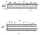
- FIG. 2depicts a cross-sectional view of an example VBC fiber 200 for adjusting beam characteristics of an optical beam.
- VBC fiber 200may be a process fiber because it may deliver the beam to a process head for material processing.
- VBC fiber 200comprises a first length of fiber 204 spliced at junction 206 to a second length of fiber 208 .
- a perturbation assembly 210is disposed proximal to junction 206 .
- Perturbation assembly 210may be any of a variety of devices configured to enable adjustment of the beam characteristics of an optical beam 202 propagating in VBC fiber 200 .
- perturbation assembly 210may be a mandrel and/or another device that may provide means of varying the bend radius and/or bend length of VBC fiber 200 near the splice. Other examples of perturbation devices are discussed below with respect to FIG. 24 .
- first length of fiber 204has a parabolic-index RIP 212 as indicated by the left RIP graph. Most of the intensity distribution of beam 202 is concentrated in the center of fiber 204 when fiber 204 is straight or nearly straight.
- Second length of fiber 208is a confinement fiber having RIP 214 as shown in the right RIP graph. Second length of fiber 208 includes confinement regions 216 , 218 and 220 .
- Confinement region 216is a central core surrounded by two annular (or ring-shaped) confinement regions 218 and 220 .
- Layers 222 and 224are structural barriers of lower index material between confinement regions ( 216 , 218 and 220 ), commonly referred to as “cladding” regions.
- layers 222 and 224may comprise rings of fluorosilicate; in some embodiments, the fluorosilicate cladding layers are relatively thin. Other materials may be used as well and claimed subject matter is not limited in this regard.
- perturbation assembly 210may physically act on fiber 208 and/or beam 202 to adjust its beam characteristics and generate adjusted beam 226 .
- the intensity distribution of beam 202is modified by perturbation assembly 210 .
- the intensity distribution of adjusted beam 226may be concentrated in outer confinement regions 218 and 220 with relatively little intensity in the central confinement region 216 .
- second length of fiber 208can substantially maintain the adjusted intensity distribution of adjusted beam 226 .
- the beamwill typically become distributed azimuthally within a given confinement region but will not transition (significantly) between the confinement regions as it propagates along the second length of fiber 208 .
- adjusted beam characteristics of adjusted beam 226are largely conserved within the isolated confinement regions 216 , 218 , and/or 220 .
- core confinement region 216 and annular confinement regions 218 and 220may be composed of fused silica glass, and cladding 222 and 224 defining the confinement regions may be composed of fluorosilicate glass.
- Other materialsmay be used to form the various confinement regions ( 216 , 218 and 220 ), including germanosilicate, phospho silicate, aluminosilicate, or the like, or a combination thereof and claimed subject matter is not so limited.
- Other materialsmay be used to form the barrier rings ( 222 and 224 ), including fused silica, borosilicate, or the like or a combination thereof, and claimed subject matter is not so limited.
- the optical fibers or waveguidesinclude or are composed of various polymers or plastics or crystalline materials.
- the core confinement regionshave refractive indices that are greater than the refractive indices of adjacent barrier/cladding regions.
- confinement regionsmay be configured to provide stepwise beam displacement.
- FIG. 3illustrates an example method of perturbing fiber 200 for providing variable beam characteristics of an optical beam.
- Changing the bend radius of a fibermay change the radial beam position, divergence angle, and/or radiance profile of a beam within the fiber.
- the bend radius of VBC fiber 200can be decreased from a first bend radius R 1 to a second bend radius R 2 about splice junction 206 by using a stepped mandrel or cone as the perturbation assembly 210 . Additionally or alternatively, the engagement length on the mandrel(s) or cone can be varied. Rollers 250 may be employed to engage VBC fiber 200 across perturbation assembly 210 .
- an amount of engagement of rollers 250 with fiber 200has been shown to shift the distribution of the intensity profile to the outer confinement regions 218 and 220 of fiber 200 with a fixed mandrel radius.
- the bend radius of fiber 200can also vary beam characteristics in a controlled and reproducible way.
- changing the bend radius and/or length over which the fiber is bent at a particular bend radiusalso modifies the intensity distribution of the beam such that one or more modes may be shifted radially away from the center of a fiber core.
- the adjusted beam characteristicssuch as radial beam position and radiance profile of optical beam 202 will not return to beam 202 ′s unperturbed state before being launched into second length of fiber 208 .
- the adjusted radial beam characteristics, including position, divergence angle, and/or intensity distribution, of adjusted beam 226can be varied based on an extent of decrease in the bend radius and/or the extent of the bent length of VBC fiber 200 . Thus, specific beam characteristics may be obtained using this method.
- first length of fiber 204 having first RIP 212is spliced at junction 206 to a second length of fiber 208 having a second RIP 214 .
- Such a RIPmay be similar to the RIPs shown in fibers illustrated in FIGS. 17, 18 , and/or 19 .
- FIGS. 7-10provide experimental results for VBC fiber 200 (shown in FIGS. 2 and 3 ) and illustrate further a beam response to perturbation of VBC fiber 200 when a perturbation assembly 210 acts on VBC fiber 200 to bend the fiber.
- FIGS. 4 6are simulations and FIGS. 7-10 are experimental results wherein a beam from a SM 1050 nm source was launched into an input fiber (not shown) with a 40 micron core diameter. The input fiber was spliced to first length of fiber 204 .
- FIG. 4is an example graph 400 illustrating the calculated profile of the lowest-order mode (LP 01 ) for a first length of fiber 204 for different fiber bend radii 402 , wherein a perturbation assembly 210 involves bending VBC fiber 200 .
- a perturbation assembly 210involves bending VBC fiber 200 .
- Higher-order modes (LP In )also shift with bending.
- curve 406 for LP 01is centered at or near the center of VBC fiber 200 .
- curve 408 for LP 01is shifted to a radial position of about 40 ⁇ m from the center 406 of VBC fiber 200 .
- curve 410 for LP 01is shifted to a radial position about 50 ⁇ m from the center 406 of VBC fiber 200 .
- curve 412 for LP 01is shifted to a radial position about 60 ⁇ m from the center 406 of VBC fiber 200 .
- curve 414 for LP 01is shifted to a radial position about 80 ⁇ m from the center 406 of VBC fiber 200 .
- a curve 416 for LP 01is shifted to a radial position about 85 ⁇ m from the center 406 of VBC fiber 200 .
- the shape of the moderemains relatively constant (until it approaches the edge of the core), which is a specific property of a parabolic RIP. Although, this property may be desirable in some situations, it is not required for the VBC functionality, and other RIPs may be employed.
- second length of fiber 208is to “trap” or confine the adjusted intensity distribution of the beam in a confinement region that is displaced from the center of the VBC fiber 200 .
- the splice between fibers 204 and 208is included in the bent region, thus the shifted mode profile will be preferentially launched into one of the ring-shaped confinement regions 218 and 220 or be distributed among the confinement regions.
- FIGS. 5 and 6illustrate this effect.
- FIG. 5illustrates an example two-dimensional intensity distribution at junction 206 within second length of fiber 208 when VBC fiber 200 is nearly straight. A significant portion of LP 01 and LP In are within confinement region 216 of fiber 208 .
- FIG. 6illustrates the two-dimensional intensity distribution at junction 206 within second length of fiber 208 when VBC fiber 200 is bent with a radius chosen to preferentially excite confinement region 220 (the outermost confinement region) of second length of fiber 208 . A significant portion of LP 01 and LP In are within confinement region 220 of fiber 208 .
- second length of fiber 208 confinement region 216has a 100 micron diameter
- confinement region 218is between 120 micron and 200 micron in diameter
- confinement region 220is between 220 micron and 300 micron diameter.
- Confinement regions 216 , 218 , and 220are separated by 10 ⁇ m thick rings of fluorosilicate, providing an NA of 0.22 for the confinement regions.
- Other inner and outer diameters for the confinement regions, thicknesses of the rings separating the confinement regions, NA values for the confinement regions, and numbers of confinement regionsmay be employed.
- VBC fiber 200when VBC fiber 200 is straight about 90% of the power is contained within the central confinement region 216 , and about 100% of the power is contained within confinement regions 216 and 218 .
- FIG. 6when fiber 200 is bent to preferentially excite second ring confinement region 220 , nearly 75% of the power is contained within confinement region 220 , and more than 95% of the power is contained within confinement regions 218 and 220 .
- These calculationsinclude LP 01 and two higher-order modes, which is typical in some 2-4 kW fiber lasers.
- the bend radiusdetermines the spatial overlap of the modal intensity distribution of the first length of fiber 204 with the different guiding confinement regions ( 216 , 218 , and 220 ) of the second length of fiber 208 .
- Changing the bend radiuscan thus change the intensity distribution at the output of the second length of fiber 208 , thereby changing the diameter or spot size of the beam, and thus also changing its radiance and BPP value.
- This adjustment of the spot sizemay be accomplished in an all-fiber structure, involving no free-space optics and consequently may reduce or eliminate the disadvantages of free-space optics discussed above.
- Such adjustmentscan also be made with other perturbation assemblies that alter bend radius, bend length, fiber tension, temperature, or other perturbations discussed below.
- the output of the process fiberis imaged at or near the work piece by the process head. Varying the intensity distribution as shown in FIGS. 5 and 6 thus enables variation of the beam profile at the work piece in order to tune and/or optimize the process, as desired.
- Specific RIPs for the two fiberswere assumed for the purpose of the above calculations, but other RIPs are possible, and claimed subject matter is not limited in this regard.
- FIGS. 7-10depict experimental results (measured intensity distributions) to illustrate further output beams for various bend radii of VBC fiber 200 shown in FIG. 2 .
- FIG. 7when VBC fiber 200 is straight, the beam is nearly completely confined to confinement region 216 .
- the intensity distributionshifts to higher diameters ( FIGS. 8-10 ).
- FIG. 8depicts the intensity distribution when the bend radius of VBC fiber 200 is chosen to shift the intensity distribution preferentially to confinement region 218 .
- FIG. 9depicts the experimental results when the bend radius is further reduced and chosen to shift the intensity distribution outward to confinement region 220 and confinement region 218 .
- the beamis nearly a “donut mode”, with most of the intensity in the outermost confinement region 220 .
- the intensity distributionsare nearly symmetric azimuthally because of scrambling within confinement regions as the beam propagates within the VBC fiber 200 .
- the beamwill typically scramble azimuthally as it propagates, various structures or perturbations (e.g., coils) could be included to facilitate this process.
- FIGS. 7-10pertain to the particular fibers used in this experiment, and the details will vary depending on the specifics of the implementation.
- the spatial profile and divergence distribution of the output beam and their dependence on bend radiuswill depend on the specific RIPs employed, on the splice parameters, and on the characteristics of the laser source launched into the first fiber.
- Example RIPs for the first length of fiberinclude other graded-index profiles, step-index, pedestal designs (i.e., nested cores with progressively lower refractive indices with increasing distance from the center of the fiber), and designs with nested cores with the same refractive index value but with various NA values for the central core and the surrounding rings.
- Example RIPs for the second length of fiberin addition to the profile shown in FIG.
- VBC fiber 200 and other examples of a VBC fiber described hereinare not restricted to use of two fibers. In some examples, implementation may include use of one fiber or more than two fibers.
- the fiber(s)may not be axially uniform; for example, they could include fiber Bragg gratings or long-period gratings, or the diameter could vary along the length of the fiber.
- the fibersdo not have to be azimuthally symmetric, e.g., the core(s) could have square or polygonal shapes.
- Various fiber coatingsmay be employed, including high-index or index-matched coatings (which strip light at the glass-polymer interface) and low-index coatings (which guide light by total internal reflection at the glass-polymer interface). In some examples, multiple fiber coatings may be used on VBC fiber 200 .
- FIGS. 11-16illustrate cross-sectional views of examples of first lengths of fiber for enabling adjustment of beam characteristics in a VBC fiber responsive to perturbation of an optical beam propagating in the first lengths of fiber.
- Some examples of beam characteristics that may be adjusted in the first length of fiberare: beam diameter, beam divergence distribution, BPP, intensity distribution, luminance, M 2 factor, NA, optical intensity profile, power density profile, radial beam position, radiance, spot size, or the like, or any combination thereof.
- the first lengths of fiber depicted in FIGS. 11-16 and described beloware merely examples and do not provide an exhaustive recitation of the variety of first lengths of fiber that may be utilized to enable adjustment of beam characteristics in a VBC fiber assembly.
- first length of fiber 1100comprises a step-index profile 1102 .
- FIG. 12illustrates a first length of fiber 1200 comprising a “pedestal RIP” (i.e., a core comprising a step-index region surrounded by a larger step-index region) 1202 .
- FIG. 13illustrates first length of fiber 1300 comprising a multiple-pedestal RIP 1302 .
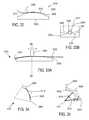
- FIG. 14Aillustrates first length of fiber 1400 comprising a graded-index profile 1418 surrounded by a down-doped region 1404 .
- modesmay shift radially outward in fiber 1400 (e.g., during bending of fiber 1400 ).
- Graded-index profile 1402may be designed to promote maintenance or even compression of modal shape. This design may promote adjustment of a beam propagating in fiber 1400 to generate a beam having a beam intensity distribution concentrated in an outer perimeter of the fiber (i.e., in a portion of the fiber core that is displaced from the fiber axis).
- the intensity distribution of the adjusted beammay be trapped in the outermost confinement region, providing a donut shaped intensity distribution.
- a beam spot having a narrow outer confinement regionmay be useful to enable certain material processing actions.
- FIG. 14Billustrates first length of fiber 1406 comprising a graded-index profile 1414 surrounded by a down-doped region 1408 similar to fiber 1400 .
- fiber 1406includes a divergence structure 1410 (a lower-index region) as can be seen in profile 1412 .
- the divergence structure 1410is an area of material with a lower refractive index than that of the surrounding core.
- refraction from divergence structure 1410causes the beam divergence to increase in first length of fiber 1406 .
- the amount of increased divergencedepends on the amount of spatial overlap of the beam with the divergence structure 1410 and the magnitude of the index difference between the divergence structure 1410 and the core material.
- Divergence structure 1410can have a variety of shapes, depending on the input divergence distribution and desired output divergence distribution. In an example, divergence structure 1410 has a triangular or graded index shape.
- FIG. 15illustrates a first length of fiber 1500 comprising a parabolic-index central region 1502 surrounded by a constant-index region 1504 , and the constant-index region 1504 is surrounded by a lower-index annular layer 1506 .
- the lower-index annulus 1506helps guide a beam propagating in fiber 1500 .
- modesshift radially outward in fiber 1500 (e.g., during bending of fiber 1500 ).
- parabolic-index region 1502promotes retention of modal shape.
- this fiber designworks with a confinement fiber having a central step-index core and a single annular core.
- the parabolic-index portion 1502 of the RIPoverlaps with the central step-index core of the confinement fiber.
- the constant-index portion 1504overlaps with the annular core of the confinement fiber.
- the constant-index portion 1504 of the first fiberis intended to make it easier to move the beam into overlap with the annular core by bending. This fiber design also works with other designs of the confinement fiber.
- FIG. 16illustrates a first length of fiber 1600 comprising guiding regions 1604 , 1606 , 1608 , and 1616 bounded by lower-index layers 1610 , 1612 , and 1614 where the indexes of the lower-index layers 1610 , 1612 , and 1614 are stepped or, more generally, do not all have the same value.
- the stepped-index layersmay serve to bound the beam intensity to certain guiding regions ( 1604 , 1606 , 1608 , and 1616 ) when the perturbation assembly 210 (see FIG. 2 ) acts on the fiber 1600 .
- adjusted beam lightmay be trapped in the guiding regions over a range of perturbation actions (such as over a range of bend radii, a range of bend lengths, a range of micro-bending pressures, and/or a range of acousto-optical signals), allowing for a certain degree of perturbation tolerance before a beam intensity distribution is shifted to a more distant radial position in fiber 1600 .
- variation in beam characteristicsmay be controlled in a step-wise fashion.
- the radial widths of the guiding regions 1604 , 1606 , 1608 , and 1616may be adjusted to achieve a desired ring width, as may be required by an application.
- a guiding regioncan have a thicker radial width to facilitate trapping of a larger fraction of the incoming beam profile if desired. Region 1606 is an example of such a design.
- FIGS. 17-21depict examples of fibers configured to enable maintenance and/or confinement of adjusted beam characteristics in the second length of fiber (e.g., fiber 208 ).
- These fiber designsare referred to as “ring-shaped confinement fibers” because they contain a central core surrounded by annular or ring-shaped cores.
- These designsare merely examples and not an exhaustive recitation of the variety of fiber RIPs that may be used to enable maintenance and/or confinement of adjusted beam characteristics within a fiber.
- claimed subject matteris not limited to the examples provided herein.
- any of the first lengths of fiber described above with respect to FIGS. 11-16may be combined with any of the second length of fiber described FIGS. 17-21 .
- FIG. 17illustrates a cross-sectional view of an example second length of fiber for maintaining and/or confining adjusted beam characteristics in a VBC fiber assembly.
- the second length of fiber 1700may maintain at least a portion of the beam characteristics adjusted in response to perturbation in the first length of fiber within one or more of confinement regions 1704 , 1706 , and/or 1708 .
- Fiber 1700has a RIP 1702 .
- Each of confinement regions 1704 , 1706 , and/or 1708is bounded by a lower index layer 1710 and/or 1712 .
- This designenables second length of fiber 1700 to maintain the adjusted beam characteristics.
- a beam output by fiber 1700will substantially maintain the received adjusted beam as modified in the first length of fiber giving the output beam adjusted beam characteristics, which may be customized to a processing task or other application.
- FIG. 18depicts a cross-sectional view of an example second length of fiber 1800 for maintaining and/or confining beam characteristics adjusted in response to perturbation in the first length of fiber in a VBC fiber assembly.
- Fiber 1800has a RIP 1802 .
- confinement regions 1808 , 1810 , and/or 1812have different thicknesses than confinement regions 1704 , 1706 , and 1708 .
- Each of confinement regions 1808 , 1810 , and/or 1812is bounded by a lower index layer 1804 and/or 1806 . Varying the thicknesses of the confinement regions (and/or barrier regions) enables tailoring or optimization of a confined adjusted radiance profile by selecting particular radial positions within which to confine an adjusted beam.
- FIG. 19depicts a cross-sectional view of an example second length of fiber 1900 having a RIP 1902 for maintaining and/or confining an adjusted beam in a VBC fiber assembly configured to provide variable beam characteristics.
- the number and thicknesses of confinement regions 1904 , 1906 , 1908 , and 1910are different from fiber 1700 and 1800 and the barrier layers 1912 , 1914 , and 1916 are of varied thicknesses as well.
- confinement regions 1904 , 1906 , 1908 , and 1910have different indexes of refraction and barrier layers 1912 , 1914 , and 1916 have different indexes of refraction as well.
- This designmay further enable a more granular or optimized tailoring of the confinement and/or maintenance of an adjusted beam radiance to particular radial locations within fiber 1900 .
- the modified beam characteristics of the beam(having an adjusted intensity distribution, radial position, and/or divergence angle, or the like, or a combination thereof) is confined within a specific radius by one or more of confinement regions 1904 , 1906 , 1908 and/or 1910 of second length of fiber 1900 .
- the divergence angle of a beammay be conserved or adjusted and then conserved in the second length of fiber.
- claimed subject matteris not limited to the examples provided herein.
- FIG. 20depicts a cross-sectional view of an example second length of fiber 2000 having RIP 2002 for modifying, maintaining, and/or confining beam characteristics adjusted in response to perturbation in the first length of fiber.
- second length of fiber 2000is similar to the previously described second lengths of fiber and forms a portion of the VBC fiber assembly for delivering variable beam characteristics as discussed above.
- Second length of fiber 2000also has a divergence structure 2014 situated within the confinement region 2006 .
- the divergence structure 2014is an area of material with a lower refractive index than that of the surrounding confinement region.
- divergence structure 2014causes the beam divergence to increase in second length of fiber 2000 .
- the amount of increased divergencedepends on the amount of spatial overlap of the beam with the divergence structure 2014 and the magnitude of the index difference between the divergence structure 2014 and the core material.
- the divergence distributionmay be varied.
- the adjusted divergence of the beamis conserved in fiber 2000 , which is configured to deliver the adjusted beam to the process head, another optical system (e.g., fiber-to-fiber coupler or fiber-to-fiber switch), the work piece, or the like, or a combination thereof.
- divergence structure 2014may have an index dip of about 10 ⁇ 5 -3 ⁇ 10 ⁇ 2 with respect to the surrounding material. Other values of the index dip may be employed within the scope of this disclosure and claimed subject matter is not so limited.
- FIG. 21depicts a cross-sectional view of an example second length of fiber 2100 having a RIP 2102 for modifying, maintaining, and/or confining beam characteristics adjusted in response to perturbation in the first length of fiber.
- Second length of fiber 2100forms a portion of a VBC fiber assembly for delivering a beam having variable characteristics.
- Second length of fiber 2100also has a plurality of divergence structures 2114 and 2118 .
- the divergence structures 2114 and 2118are areas of graded lower index material.
- divergence structure 2114 and 2118causes the beam divergence to increase.
- the amount of increased divergencedepends on the amount of spatial overlap of the beam with the divergence structure and the magnitude of the index difference between the divergence structure 2114 and/or 2118 and the surrounding core material of confinement regions 2106 and 2104 respectively.
- the divergence distributionmay be varied. The design shown in FIG. 21 allows the intensity distribution and the divergence distribution to be varied somewhat independently by selecting both a particular confinement region and the divergence distribution within that conferment region (because each confinement region may include a divergence structure).
- the adjusted divergence of the beamis conserved in fiber 2100 , which is configured to deliver the adjusted beam to the process head, another optical system, or the work piece.
- Forming the divergence structures 2114 and 2118 with a graded or non-constant indexenables tuning of the divergence profile of the beam propagating in fiber 2100 .
- An adjusted beam characteristicsuch as a radiance profile and/or divergence profile may be conserved as it is delivered to a process head by the second fiber.
- an adjusted beam characteristicsuch as a radiance profile and/or divergence profile may be conserved or further adjusted as it is routed by the second fiber through a fiber-to-fiber coupler (FFC) and/or fiber-to-fiber switch (FFS) and to a process fiber, which delivers the beam to the process head or the work piece.
- FFCfiber-to-fiber coupler
- FFSfiber-to-fiber switch
- FIGS. 26-28are cross-sectional views illustrating examples of fibers and fiber RIPs configured to enable maintenance and/or confinement of adjusted beam characteristics of a beam propagating in an azimuthally asymmetric second length of fiber wherein the beam characteristics are adjusted responsive to perturbation of a first length of fiber coupled to the second length of fiber and/or perturbation of the beam by a perturbation device 110 .
- These azimuthally asymmetric designsare merely examples and are not an exhaustive recitation of the variety of fiber RIPs that may be used to enable maintenance and/or confinement of adjusted beam characteristics within an azimuthally asymmetric fiber.
- claimed subject matteris not limited to the examples provided herein.
- any of a variety of first lengths of fibere.g., like those described above
- any azimuthally asymmetric second length of fibere.g., like those described in FIGS. 26-28 ).
- FIG. 26illustrates RIPs at various azimuthal angles of a cross-section through an elliptical fiber 2600 .
- fiber 2600has a first RIP 2604 .
- fiber 2600has a second RIP 2608 .
- fiber 2600has a third RIP 2612 .
- First, second and third RIPs 2604 , 2608 and 2612are all different.
- FIG. 27illustrates RIPs at various azimuthal angles of a cross-section through a multicore fiber 2700 .
- fiber 2700has a first RIP 2704 .
- fiber 2700has a second RIP 2708 .
- First and second RIPs 2704 and 2708are different.
- perturbation device 110may act in multiple planes in order to launch the adjusted beam into different regions of an azimuthally asymmetric second fiber.
- FIG. 28illustrates RIPs at various azimuthal angles of a cross-section through a fiber 2800 having at least one crescent shaped core. In some cases, the corners of the crescent may be rounded, flattened, or otherwise shaped, which may minimize optical loss.
- fiber 2800has a first RIP 2804 .
- fiber 2800has a second RIP 2808 .
- First and second RIPs 2804 and 2808are different.
- FIG. 22Aillustrates an example of a laser system 2200 including a VBC fiber assembly 2202 configured to provide variable beam characteristics.
- VBC fiber assembly 2202comprises a first length of fiber 104 , second length of fiber 108 , and a perturbation device 110 .
- VBC fiber assembly 2202is disposed between feeding fiber 2212 (i.e., the output fiber from the laser source) and VBC delivery fiber 2240 .
- VBC delivery fiber 2240may comprise second length of fiber 108 or an extension of second length of fiber 108 that modifies, maintains, and/or confines adjusted beam characteristics.
- Beam 2210is coupled into VBC fiber assembly 2202 via feeding fiber 2212 .
- Fiber assembly 2202is configured to vary the characteristics of beam 2210 in accordance with the various examples described above.
- the output of fiber assembly 2202is adjusted beam 2214 which is coupled into VBC delivery fiber 2240 .
- VBC delivery fiber 2240delivers adjusted beam 2214 to free-space optics assembly 2208 , which then couples beam 2214 into a process fiber 2204 .
- Adjusted beam 2214is then delivered to process head 2206 by process fiber 2204 .
- the process headcan include guided wave optics (such as fibers and fiber coupler), free space optics such as lenses, mirrors, optical filters, diffraction gratings), beam scan assemblies such as galvanometer scanners, polygonal mirror scanners, or other scanning systems that are used to shape the beam 2214 and deliver the shaped beam to a workpiece.
- one or more of the free-space optics of assembly 2208may be disposed in an FFC or other beam coupler 2216 to perform a variety of optical manipulations of an adjusted beam 2214 (represented in FIG. 22A with different dashing than beam 2210 ).
- free-space optics assembly 2208may preserve the adjusted beam characteristics of beam 2214 .
- Process fiber 2204may have the same RIP as VBC delivery fiber 2240 .
- the adjusted beam characteristics of adjusted beam 2214may be preserved all the way to process head 2206 .
- Process fiber 2204may comprise a RIP similar to any of the second lengths of fiber described above, including confinement regions.
- FFCscan include one, two, or more lenses, but in typical examples, two lenses having the same nominal focal length are used, producing unit magnification. In most practical examples, magnification produced with an FFC is between 0.8 and 1.2, which corresponds to a ratio of focal lengths.
- free-space optics assembly 2208may change the adjusted beam characteristics of beam 2214 by, for example, increasing or decreasing the divergence and/or the spot size of beam 2214 (e.g., by magnifying or demagnifying beam 2214 ) and/or otherwise further modifying adjusted beam 2214 .
- process fiber 2204may have a different RIP than VBC delivery fiber 2240 . Accordingly, the RIP of process fiber 2204 may be selected to preserve additional adjustment of adjusted beam 2214 made by the free-space optics of assembly 2208 to generate a twice adjusted beam 2224 (represented in FIG. 22B with different dashing than beam 2214 ).
- FIG. 23illustrates an example of a laser system 2300 including VBC fiber assembly 2302 disposed between feeding fiber 2312 and VBC delivery fiber 2340 .
- beam 2310is coupled into VBC fiber assembly 2302 via feeding fiber 2312 .
- Fiber assembly 2302includes a first length of fiber 104 , second length of fiber 108 , and a perturbation device 110 and is configured to vary characteristics of beam 2310 in accordance with the various examples described above.
- Fiber assembly 2302generates adjusted beam 2314 output by VBC delivery fiber 2340 .
- VBC delivery fiber 2340comprises a second length of fiber 108 of fiber for modifying, maintaining, and/or confining adjusted beam characteristics in a fiber assembly 2302 in accordance with the various examples described above (see FIGS. 17-21 , for example).
- VBC delivery fiber 2340couples adjusted beam 2314 into beam switch (FFS) 2332 , which then couples its various output beams to one or more of multiple process fibers 2304 , 2320 , and 2322 .
- Process fibers 2304 , 2320 , and 2322deliver adjusted beams 2314 , 2328 , and 2330 to respective process heads 2306 , 2324 , and 2326 .
- beam switch 2332includes one or more sets of free-space optics 2308 , 2316 , and 2318 configured to perform a variety of optical manipulations of adjusted beam 2314 .
- Free-space optics 2308 , 2316 , and 2318may preserve or vary adjusted beam characteristics of beam 2314 .
- adjusted beam 2314may be maintained by the free-space optics or adjusted further.
- Process fibers 2304 , 2320 , and 2322may have the same or a different RIP as VBC delivery fiber 2340 , depending on whether it is desirable to preserve or further modify a beam passing from the free-space optics assemblies 2308 , 2316 , and 2318 to respective process fibers 2304 , 2320 , and 2322 .
- one or more beam portions of beam 2310are coupled to a workpiece without adjustment, or different beam portions are coupled to respective VBC fiber assemblies so that beam portions associated with a plurality of beam characteristics can be provided for simultaneous workpiece processing.
- beam 2310can be switched to one or more of a set of VBC fiber assemblies.
- Routing adjusted beam 2314 through any of free-space optics assemblies 2308 , 2316 , and 2318enables delivery of a variety of additionally adjusted beams to process heads 2206 , 2324 , and 2326 . Therefore, laser system 2300 provides additional degrees of freedom for varying the characteristics of a beam, as well as switching the beam between process heads (“time sharing”) and/or delivering the beam to multiple process heads simultaneously (“power sharing”).
- free-space optics in beam switch 2332may direct adjusted beam 2314 to free-space optics assembly 2316 configured to preserve the adjusted characteristics of beam 2314 .
- Process fiber 2304may have the same RIP as VBC delivery fiber 2340 .
- the beam delivered to process head 2306will be a preserved adjusted beam 2314 .
- beam switch 2332may direct adjusted beam 2314 to free-space optics assembly 2318 configured to preserve the adjusted characteristics of adjusted beam 2314 .
- Process fiber 2320may have a different RIP than VBC delivery fiber 2340 and may be configured with divergence altering structures as described with respect to FIGS. 20 and 21 to provide additional adjustments to the divergence distribution of beam 2314 .
- the beam delivered to process head 2324will be a twice adjusted beam 2328 having a different beam divergence profile than adjusted beam 2314 .
- Process fibers 2304 , 2320 , and/or 2322may comprise a RIP similar to any of the second lengths of fiber described above, including confinement regions or a wide variety of other RIPs, and claimed subject matter is not limited in this regard.
- free-space optics switch 2332may direct adjusted beam 2314 to free-space optics assembly 2308 configured to change the beam characteristics of adjusted beam 2314 .
- Process fiber 2322may have a different RIP than VBC delivery fiber 2340 and may be configured to preserve (or alternatively further modify) the new further adjusted characteristics of beam 2314 .
- the beam delivered to process head 2326will be a twice adjusted beam 2330 having different beam characteristics (due to the adjusted divergence profile and/or intensity profile) than adjusted beam 2314 .
- the optics in the FFC or FFSmay adjust the spatial profile and/or divergence profile by magnifying or demagnifying the beam 2214 before launching into the process fiber. They may also adjust the spatial profile and/or divergence profile via other optical transformations. They may also adjust the launch position into the process fiber. These methods may be used alone or in combination.
- FIGS. 22A, 22B, and 23merely provide examples of combinations of adjustments to beam characteristics using free-space optics and various combinations of fiber RIPs to preserve or modify adjusted beams 2214 and 2314 .
- the examples provided aboveare not exhaustive and are meant for illustrative purposes only. Thus, claimed subject matter is not limited in this regard.
- FIG. 24illustrates various examples of perturbation devices, assemblies or methods (for simplicity referred to collectively herein as “perturbation device 110 ”) for perturbing a VBC fiber 200 and/or an optical beam propagating in VBC fiber 200 according to various examples provided herein.
- Perturbation device 110may be any of a variety of devices, methods, and/or assemblies configured to enable adjustment of beam characteristics of a beam propagating in VBC fiber 200 .
- perturbation device 110may be a mandrel 2402 , a micro-bend 2404 in the VBC fiber, flexible tubing 2406 , an acousto-optic transducer 2408 , a thermal device 2410 , a piezo-electric device 2412 , a grating 2414 , a clamp 2416 (or other fastener), or the like, or any combination thereof.
- perturbation devices 100may be a mandrel 2402 , a micro-bend 2404 in the VBC fiber, flexible tubing 2406 , an acousto-optic transducer 2408 , a thermal device 2410 , a piezo-electric device 2412 , a grating 2414 , a clamp 2416 (or other fastener), or the like, or any combination thereof.
- Mandrel 2402may be used to perturb VBC fiber 200 by providing a form about which VBC fiber 200 may be bent. As discussed above, reducing the bend radius of VBC fiber 200 moves the intensity distribution of the beam radially outward.
- mandrel 2402may be stepped or conically shaped to provide discrete bend radii levels.
- mandrel 2402may comprise a cone shape without steps to provide continuous bend radii for more granular control of the bend radius.
- the radius of curvature of mandrel 2402may be constant (e.g., a cylindrical form) or non-constant (e.g., an oval-shaped form).
- VBC fiber 200 and mandrel 2402may be configured to change the intensity distribution within the first fiber predictably (e.g., in proportion to the length over which the fiber is bent and/or the bend radius).
- Rollers 250may move up and down along a track 2442 on platform 2434 to change the bend radius of VBC fiber 200 .
- Clamps 2416may be used to guide and control the bending of VBC fiber 200 with or without a mandrel 2402 .
- Clamps 2416may move up and down along a track 2442 or platform 2446 .
- Clamps 2416may also swivel to change bend radius, tension, or direction of VBC fiber 200 .
- Controller 2448may control the movement of clamps 2416 .
- perturbation device 110may be flexible tubing 2406 and may guide bending of VBC fiber 200 with or without a mandrel 2402 .
- Flexible tubing 2406may encase VBC fiber 200 .
- Tubing 2406may be made of a variety of materials and may be manipulated using piezoelectric transducers controlled by controller 2444 . In another example, clamps or other fasteners may be used to move flexible tubing 2406 .
- Micro-bend 2404 in VBC fiberis a local perturbation caused by lateral mechanical stress on the fiber. Micro-bending can cause mode coupling and/or transitions from one confinement region to another confinement region within a fiber, resulting in varied beam characteristics of the beam propagating in a VBC fiber 200 .
- Mechanical stressmay be applied by an actuator 2436 that is controlled by controller 2440 .
- thisis merely an example of a method for inducing mechanical stress in fiber 200 and claimed subject matter is not limited in this regard.
- Acousto-optic transducer (AOT) 2408may be used to induce perturbation of a beam propagating in the VBC fiber using an acoustic wave.
- the perturbationis caused by the modification of the refractive index of the fiber by the oscillating mechanical pressure of an acoustic wave.
- the period and strength of the acoustic waveare related to the acoustic wave frequency and amplitude, allowing dynamic control of the acoustic perturbation.
- a perturbation assembly 110 including AOT 2408may be configured to vary the beam characteristics of a beam propagating in the fiber.
- piezo-electric transducer 2418may create the acoustic wave and may be controlled by controller or driver 2420 .
- the acoustic wave induced in AOT 2408may be modulated to change and/or control the beam characteristics of the optical beam in VBC 200 in real-time.
- thisis merely an example of a method for creating and controlling an AOT 2408 and claimed subject matter is not limited in this regard.
- Thermal device 2410may be used to induce perturbation of a beam propagating in VBC fiber using heat.
- the perturbationis caused by the modification of the RIP of the fiber induced by heat.
- Perturbationmay be dynamically controlled by controlling an amount of heat transferred to the fiber and the length over which the heat is applied.
- a perturbation assembly 110 including thermal device 2410may be configured to vary a range of beam characteristics.
- Thermal device 2410may be controlled by controller 2450 .
- Piezo-electric transducer 2412may be used to induce perturbation of a beam propagating in a VBC fiber using piezoelectric action.
- the perturbationis caused by the modification of the RIP of the fiber induced by a piezoelectric material attached to the fiber.
- the piezoelectric material in the form of a jacket around the bare fibermay apply tension or compression to the fiber, modifying its refractive index via the resulting changes in density.
- Perturbationmay be dynamically controlled by controlling a voltage to the piezo-electric device 2412 .
- a perturbation assembly 110 including piezo-electric transducer 2412may be configured to vary the beam characteristics over a particular range.
- piezo-electric transducer 2412may be configured to displace VBC fiber 200 in a variety of directions (e.g., axially, radially, and/or laterally) depending on a variety of factors, including how the piezo-electric transducer 2412 is attached to VBC fiber 200 , the direction of the polarization of the piezo-electric materials, the applied voltage, etc. Additionally, bending of VBC fiber 200 is possible using the piezo-electric transducer 2412 . For example, driving a length of piezo-electric material having multiple segments comprising opposing electrodes can cause a piezoelectric transducer 2412 to bend in a lateral direction.
- Voltage applied to piezoelectric transducer 2412 by electrode 2424may be controlled by controller 2422 to control displacement of VBC fiber 200 .
- Displacementmay be modulated to change and/or control the beam characteristics of the optical beam in VBC 200 in real-time.
- thisis merely an example of a method of controlling displacement of a VBC fiber 200 using a piezo-electric transducer 2412 and claimed subject matter is not limited in this regard.
- Gratings 2414may be used to induce perturbation of a beam propagating in a VBC fiber 200 .
- a grating 2414can be written into a fiber by inscribing a periodic variation of the refractive index into the core.
- Gratings 2414such as fiber Bragg gratings can operate as optical filters or as reflectors.
- a long-period gratingcan induce transitions among co-propagating fiber modes. The radiance, intensity profile, and/or divergence profile of a beam comprised of one or more modes can thus be adjusted using a long-period grating to couple one or more of the original modes to one or more different modes having different radiance and/or divergence profiles.
- Adjustmentis achieved by varying the periodicity or amplitude of the refractive index grating. Methods such as varying the temperature, bend radius, and/or length (e.g., stretching) of the fiber Bragg grating can be used for such adjustment.
- VBC fiber 200 having gratings 2414may be coupled to stage 2426 .
- Stage 2426may be configured to execute any of a variety of functions and may be controlled by controller 2428 .
- stage 2426may be coupled to VBC fiber 200 with fasteners 2430 and may be configured to stretch and/or bend VBC fiber 200 using fasteners 2430 for leverage.
- Stage 2426may have an embedded thermal device and may change the temperature of VBC fiber 200 .
- FIG. 25illustrates an example process 2500 for adjusting and/or maintaining beam characteristics within a fiber without the use of free-space optics to adjust the beam characteristics.
- a first length of fiber and/or an optical beamare perturbed to adjust one or more optical beam characteristics.
- Process 2500moves to block 2504 , where the optical beam is launched into a second length of fiber.
- Process 2500moves to block 2506 , where the optical beam having the adjusted beam characteristics is propagated in the second length of fiber.
- Process 2500moves to block 2508 , where at least a portion of the one or more beam characteristics of the optical beam are maintained within one or more confinement regions of the second length of fiber.
- the first and second lengths of fibermay be comprised of the same fiber, or they may be different fibers.
- a variable beam characteristics (VBC) apparatus 2900includes a disc 2902 .
- the disc 2902is a perturbation assembly having circular, elliptical, or other curved cross-section defining a perimeter surface 2904 that serves as a fiber bending or fiber shaping surface.
- Fiber guides 2906 , 2908are situated at the perimeter surface 2904 to urge a section of a first fiber 2910 toward the perimeter surface 2904 .
- the fiber guides 2906 , 2908are secured to spokes 2907 , 2909 that are connected to permit the fiber guides 2906 , 2908 be rotatable about an axis 2912 .
- a separation of the guides 2906 , 2908 along the perimeter surface 2904defines an angle 0 that is associated with a length of a section of the first fiber 2910 that conforms to or is urged to contact the perimeter surface 2904 .
- Rotation of one or both of the guides 2906 , 2908permits selection of a suitable length.
- a fiberis secured to a guide such as the guide 2908 , and rotation of the guide wraps a fiber about a fiber bending surface, thereby selecting a fiber length to be bent based on rotation of a guide.
- a tension mechanismcan be provided so that the fiber unwinds from a fiber bending surface as the guide rotates to unwrap the fiber.
- the guides 2906 , 2908can include surfaces that press fibers toward the fiber bending surface.
- the guides 2906 , 2908can be made of or include an elastic portion of rubber, foam, cloth, fibers, or other material than can be urged against a fiber without compromising fiber integrity and to accommodate sharp surface irregularities that could damage fibers.
- the fiber bending surfacesuch as the perimeter surface 2904 can be provided with a similar material along the entire surface or only at portions expected to be used in conforming fibers.
- the guides 2906 , 2908can include grooves such as a groove 2916 that retains a fiber and may or may not press the fiber against the fiber bending surface. For guides that are rotatable, grooves may extend around the entire perimeter so that a fiber is retained in the groove as the guide rotates and travels along the fiber bending surface.
- the first fiber 2910is typically connected to a second fiber 2920 with a splice 2918 such as a fusion splice (shown in possible two locations in FIG. 29A ).
- a splice 2918such as a fusion splice (shown in possible two locations in FIG. 29A ).
- the guides 2906 , 2908then urge a section of the second fiber into a bent path along the perimeter surface 2904 (along with the splice 2918 ).
- the spokes 2907 , 2909are rigid, but in other examples, elastic members such as springs can be used (or spokes can include an elastic portion) so that the guides 2906 , 2908 are pulled toward the perimeter surface 2904 .
- first guideis used, but one, two, three, or more can be used to select portions of one or more fibers to be conformed to the fiber bending surface 2904 .
- sections of the first fiber 2910 and the second fiber 2920can be independently selected to be urged toward the perimeter surface using respective pairs of guides.
- Locations of the guides 2906 , 2908can be controlled using motor 2930 that is coupled to the spokes 2907 , 2909 to rotate to establish the angle ⁇ .
- a controller 2932is coupled to the motor 2930 so that the guides 2906 , 2908 can be computer or processor controlled, or controlled manually.
- the controller 2932includes a non-transitory computer readable medium that includes a calibration table in which the angle ⁇ and associated beam characteristics are stored. In systems having multiple guides, each can be arranged to be independently moved, and sections of one or more fibers can be selected.
- a single bend radiusis associated with a fiber bending surface, but in other examples, series of different bend radii can be used, each defined with a corresponding step formed as, for example, a portion of a cylinder, or on a tapered surface such as a cone or portion thereof. Arcuate or other curved surfaces can be used as well.
- Guidescan be situated to direct fibers to a fiber bending or shaping surface having a particular curvature as well as selecting a length of fiber to be shaped into that curvature.
- Fiber sectionscan be bent at a plurality of surface areas having associated curvatures and section lengths can be varied for each curvature. Cylindrical curvatures are shown in FIGS.
- the perimeter surface 2904is an exterior surface of the disc 2902 , but in other examples, interior surfaces of rings, hollow cylinders, or other shapes can be used as fiber bending or shaping surfaces, and guides situated to adjust fiber shape with respect to such interior surfaces.
- an optical fiber that includes a length of a first optical fiber and a second optical fiber that are fusion splicedis bent at or near the fusion splice so as to vary a spatial beam profile or other beam characteristic produced in the first fiber or the second fiber. More efficient adjustment of spatial beam profile is typically achieved if the fusion splice is included in the bent portion of the fiber. However, the fusion splice can be located sufficiently close to the bent portion. Typically, the fusion splice should be situated within a length of less than about 2, 5, 10, 50, 100, 500, or 1000 times a core diameter of either fiber. Sufficient fiber lengths can also depend on fiber numerical aperture as well.
- One possible explanation for the utility of bending either the first fiber or the second fiberis that bending of a fiber near a launch point, which is at the spliced junction 2918 , can produce a variable spatial beam profile that propagates some distance before collapsing to an original beam shape.
- bending near a splicecan perturb a spatial power distribution from the launching (first) fiber, and thus variably couple the received power into a selected spatial power distribution.
- the disclosureis not limited to operation in accordance with operation in this way, and this explanation is only provided as one potential explanation for convenience.
- the perturbation assembly disc 2902is disposed proximal to the spliced junction 2918 .
- a perturbation assemblymay not be disposed near a splice.
- a splicemay not be needed at all, for example the fiber 2910 may be a single fiber, a first length of fiber and second length of fiber could be spaced apart, or secured with a small gap (air-spaced or filled with an optical material, such as optical cement or an index-matching material).
- the bend radius of a fiberis changed from a first bend radius R 1 to a second bend radius R 2 by using a stepped mandrel or a cone in a perturbation assembly.
- Fiber portions having different bend radiican be independently selected. Changing a bend radius of a fiber may change the radial beam position, divergence angle, and/or radiance profile, or other beam characteristics of a beam within the fiber.
- a disk 3002defines a perimeter (fiber bending) surface 3004 that is provided with grooves 3010 , 3011 .
- the disk 3002includes a central bore 3006 for insertion of a rotatable shaft (not shown).
- a guide 3008includes protrusions 3016 , 3017 that can be inserted in the grooves 3010 , 3011 so that the guide 3008 is movable along the perimeter surface 3004 .
- a fiber 3014is shown situated in a groove 3015 in the guide 3008 .
- guidescan have dovetail shaped protrusions to fit into correspond grooves in a disk or other support.
- groovescan be provided in the guide, and protrusions in the disk, or any combination thereof as may be convenient.
- a VBC apparatus 3100includes an ellipsoidal disk 3102 having a perimeter (fiber bending) surface 3104 .
- Guides 3106 , 3107are situated to select a length of a fiber 3108 that conforms to the fiber bending surface 3104 .
- the guide 3106is fixed with respect to the perimeter surface 3104
- the guide 3107is configured to be movable along the perimeter surface 3104 .
- the guide 3107is secured with an elastic member 3110 so as to be rotatable about an axis 3112 .
- the perimeter surface 3104is defined by an ellipse and thus has a varying radius of curvature, and the elastic member 3110 is selected to permit the guide 3107 to accommodate varying distances from the axis 3112 to the perimeter surface 3104 .
- FIG. 32illustrates an additional fiber bending surface 3202 that is formed on a substrate 3200 .
- a surface 3206 opposite the fiber bending surface 3202can be planar, or have a convex or concave curvature.
- a guide 3208is situated to urge a fiber against the fiber bending surface 3202 , and one, two, three, or more such guides can be used. As discussed above, the guide 3208 can be retained by a groove and be slidable, or can be coupled to an elastic member that urges the guide 3208 toward the fiber bending surface 3202 .
- the fiber bending surface 3202can have various simple or complex curvatures, and can be convex, concave, or planar in at least some portions.
- the guide 3208can be spherical or cylindrical and arranged to roll along the fiber bending surface 3204 .
- the guide 3208is situated to urge a fiber 3210 to contact the fiber bending surface 3202 , to change a bend angle of the fiber 3210 , or bend the fiber 3210 while leaving a gap 3212 between the fiber 3210 and the fiber bending surface 3202 proximate the guide 3208 .
- a guide 3304is situated to urge a fiber 3306 toward a fiber bending surface 3308 .
- the fiber 3306can be secured with respect to the fiber bending surface 3308 with a clip 3310 or otherwise fixed so that a length of fiber conformed to the fiber bending surface 3208 is determined by a position of the guide 3304 .
- the fiber 3306is retained in a channel 3312 , and the guide 3304 includes protrusions 3320 , 3321 that correspond to grooves 3330 , 3331 in the fiber bending surface 3308 .
- a section 3402 of a diskdefines a fiber bending surface 3404 .
- a clamp 3406secures a fiber 3408 to the fiber bending surface 3404 and a guide 3410 is movable along the fiber bending surface 3404 to control a fiber length that is urged toward the fiber bending surface 3404 .
- the guide 3410can move along the surface in grooves and/or be secured to an axis that permits rotation.
- a portion 3502 of ringdefines a fiber bending surface 3504 .
- a clamp 3506 and a guide 3510are provided to adjust a fiber length that is conformed to the fiber bending surface 3504 .
- the guide 3510can be slidable along the fiber bending surface 3504 in grooves or otherwise, or coupled to a spoke to rotate along an axis.
- a fiber bending surfaceis rotatable or otherwise adjustable so that a separation of a clamp fixed with respect to the fiber bending surface and a guide is adjustable.
- a spoke 3512can permit movement of the guide 3510 along the fiber bending surface 3504 and/or a spoke 3514 can be coupled to permit rotation of the ring 3502 with respect to the guide 3510 .
- Such rotation or movement of a fiber bending surfacecan be accomplished by rotation of a disk, cylinder, or other shape that defines the fiber bending surface.
- a VBC apparatus 3600includes a flexible plate 3602 that is situated to be flexed against fixed supports 3604 , 3606 by a linear actuator 3608 that urges a bearing 3610 toward the flexible plate 3602 .
- a fiber 3612is secured to the flexible plate 3602 or otherwise situated so as to bend in response to flexing of the flexible plate 3602 .
- FIGS. 37A-37Billustrate a spool 3700 that includes a groove or channel 3704 that is configured to retain one or more loops of a fiber 3702 .
- Rotation of the spool 3700(or the fiber about the spool 3700 ) permits adjustment of a beam perturbation applied by the fiber 3702 .
- Other arrangementscan be provided that permit varying a number of wraps of a fiber on a substrate, and typically a section of a cylinder can suffice.
- a controlleris generally provided to select a number of wraps (turns) by controlling a stepper motor or other motor, but in some examples, the number of turns can be adjusted manually. While it may be convenient that the fiber 3702 contact a radially innermost portion of the groove 3704 , this is not required.
- a VBC device 3800includes a cylinder 3804 that is situated to press a fiber loop 3802 towards a first jaw 3806 and a second jaw 3808 in response to translation of a rod 3812 that is secured to the cylinder 3804 .
- One or more springssuch as representative spring 3810 are situated to urge one or both of the jaws 3806 , 3808 toward the fiber 3802 and the cylinder 3804 .
- FIG. 38Ashows the fiber loop 3802 without deformation for convenient illustration; with the configuration of FIG. 38B , substantial bending of the fiber loop 3802 would be obtained.
- Various shapescan be used to press the fiber loop 3802 such as cylindrical, spherical, ellipsoidal, arcuate, or other shapes, and a cylinder is shown for convenient illustration.
- FIGS. 39A-39Dillustrate fiber shape with various engagements of the mechanism of FIGS. 38A-38B .
- a fiberremains in a loop 3900 without bending or deformation.
- FIGS. 39B-39Cshow fiber sections 3902 , 3904 , 3906 that contact the jaws 3806 , 3808 and the cylinder 3804 as engagement of the mechanism is increased.
- the shape of the loop 3900changes as well.
- FIG. 40illustrates a VBC apparatus 4000 for perturbing beam characteristics that includes a first set 4002 and a second set 4004 of cylinders or other suitable shapes that are situated opposite each other.
- a fiber 4008is situated between the first set 4002 and the second set 4004 so as to be bent or deformed as the first set 4002 and the second set 3004 are urged toward each other.
- cylinders of the same shapeare shown, but one or more of the cylinders of either set can have different diameters, and different shapes can be used for each surface of each set.
- a plurality of fiber shaping surfacescan be defined on a single substrate, if convenient, as shown in FIG. 41 .
- a plate 4100includes elliptical or other protrusions 4101 , 4102 , 4103 , 4104 that provide fiber shaping surfaces. Cylindrical, arcuate, spherical, parabolic, or other shapes can be used.
- FIG. 42illustrates a VBC apparatus 4200 that is similar to that of FIG. 36 but in which a flexible plate 4202 is pulled against stops 4204 , 4206 with a linear actuator 4208 that is coupled to the flexible plate 4202 with an elastic or rigid coupling 4210 .
- a fiber 4212is situated to conform to a shape of the flexible plate 4202 .
- a beam perturbation mechanism 4300includes a cylinder 4304 having a central bore 4306 that can accommodate a drive shaft.
- An outer surface 4305 of the cylinder 4304serves as a fiber shaping surface.
- a fiber 4302is shown as having been wrapped about the cylinder 4304 several times. Rotation of the cylinder 4304 can be used to provide a selected beam perturbation, either manually, or with a processor-based control system that can store beam perturbation characteristics as a function of rotation angle in one or more non-transitory computer-readable media.
- FIGS. 44A-44Billustrate a VBC device 4400 that includes a substrate 4402 formed at least in part of an ionic polymer composite (IPC) and having a first major surface 4404 and second major surface 4405 . Electrodes 4406 , 4408 are situated on or at the first major surface 4404 and the second major surface 4405 , respectively. In some cases there are intervening layers such as non-conductive layers, protective layers, or other layers needed for fabrication or use, but such layers are not shown.
- a serpentine fiber loop 4410is secured to the first major surface 4404 and is shaped to have elongated portions such as elongated portion 4411 that extends along an X-axis of a right handed Cartesian coordinate system 4450 . As shown in the sectional view of FIG.
- a VBC device 4500includes an IPC substrate 4502 to which fiber serpentine loops 4504 , 4505 (or circular loops or fibers arranged in other shapes) are secured so as to be subject to flexing of the IPC substrate 4502 . Electrodes such as electrode 4506 are provided at ends of the IPC substrate 4502 , but can be situated in other portions or cover the substrate 4502 . Fiber ends 4510 , 4511 can be used to couple optical beams into and out of the beam perturbation device 4500 . As in other examples discussed above, the fiber serpentine loops 4504 , 4505 can be of a single fiber (a first fiber) or a first fiber and a second fiber with a splice.
- FIG. 46illustrates a VBC system 4600 that includes input optics 4601 that couple one or more beams to a beam perturbation device 4602 and output optics 4604 which receive one or more perturbed beams for delivery to a substrate, or for other use.
- a control system 4608can include control circuits, processors such as microprocessors or other programmable logic devices, memory such as RAM or ROM that stores processor-executable instructions for control of the beam perturbation device 4602 including, for example, one or more calibration tables containing beam perturbations as functions of beam perturbation device drive level.
- the beam perturbation device 4602can include one or more actuators or motors such as linear or stepper motors, piezoelectric stages, piezoelectric actuators, piezobending motors, bi-metallic strips (with thermal control), rotary motors, or voice coil motors.
- the control systemcan include a digital to analog convertor (DAC) for setting drive levels to the beam perturbation device.
- DACdigital to analog convertor
- IPC-based beam perturbation devicesare responsive to applied voltages that can be provided by a DAC.
- a user interface (UI) 4612is typically provided that can include one or more computer input or pointing devices such as a mouse, trackpad, keyboard, or touchscreen for setting, adjusting, and recording and storing beam perturbation values.
- controlis via remote network connection and the control system 4608 includes a wired or wireless network interface.
- the UI 4612can also include switches, potentiometers, and other devices for use in controlling the beam perturbation device 4602 .
- the beam perturbation device 4602includes a control system.
- a sensor 4610is situated to determine beam perturbation or a condition of the beam perturbation device.
- the sensor 4610is coupled to the control system 4608 to correct errors and drifts in beam perturbations, and/or to verify that the beam perturbation device is operating as intended.
- VBC apparatusthat include an ionic polymer layer can be provided with one or more additional electrodes that are coupled to an amplifier or other circuit to produce a signal indicative of layer deformation. This signal can be used to stabilize ionic polymer deformation.
- position, rotation, distance or other sensorscan be included so that perturbations produced by a perturbation device can be detected and controlled to maintain a selected perturbation.
- FIG. 47Aillustrates a VBC apparatus 4700 in which a fiber 4702 is secured to or guided by supports 4704 , 4706 .
- a fiber deflection member 4708(shown for purposes of illustration as having a circular cross-section) is situated to deflect an end portion 4703 of the fiber 4702 .
- the end portion 4703can include a splice region 4704 in which a first fiber and a second fiber are spliced.
- the fiber deflection member 4708is situated to push against the fiber 4702 to increase fiber deflection and pull the fiber to decrease fiber deflection, but can be situated to push to decrease deflection and pull to increase deflection.
- a VBC apparatus 4720includes a fiber 4722 that is in contact with, secured to, or otherwise restrained by a support 4724 .
- a fiber deflection member 4728is situated to deflect the fiber 4722 at a location at, near, or in a splice region 4730 in which a first fiber portion and a second fiber portion are spliced together.
- the fiber deflection members 4708 , 4728can have various shapes and sizes and can be coupled to piezoelectric devices, linear motors, or other actuators that provide displacement.
- a VBC apparatus 4750includes a fiber 4752 that is in contact with, secured to, or otherwise restrained by supports 4754 , 4756 .
- a fiber deflection member 4758is situated to deflect the fiber 4752 at a location at, near, or in a splice region 4760 in which a first fiber portion and a second fiber portion are spliced together.
- the VBC apparatus 4700 , 4720 , 4750do not include a fiber bending surface. Such a surface is convenient is some embodiments as shown above, but is not required.
- fiber deflectionsare used.
- the fiber deflection members 4708 , 4728 , 4758can have various shapes and sizes and can be coupled to piezoelectric devices, linear motors, or other actuators to provide displacements.
Landscapes
- Chemical & Material Sciences (AREA)
- Physics & Mathematics (AREA)
- Engineering & Computer Science (AREA)
- Materials Engineering (AREA)
- Organic Chemistry (AREA)
- Optics & Photonics (AREA)
- General Physics & Mathematics (AREA)
- Life Sciences & Earth Sciences (AREA)
- General Life Sciences & Earth Sciences (AREA)
- Geochemistry & Mineralogy (AREA)
- Manufacturing & Machinery (AREA)
- Lasers (AREA)
- Optical Couplings Of Light Guides (AREA)
Abstract
Description
- 1. The term “beam characteristics” refers to one or more of the following terms used to describe an optical beam. In general, the beam characteristics of most interest depend on the specifics of the application or optical system.
- 2. The term “beam diameter” is defined as the distance across the center of the beam along an axis for which the irradiance (intensity) equals 1/e2of the maximum irradiance. While examples disclosed herein generally use beams that propagate in azimuthally symmetric modes, elliptical or other beam shapes can be used, and beam diameter can be different along different axes. Circular beams are characterized by a single beam diameter. Other beam shapes can have different beam diameters along different axes.
- 3. The term “spot size” is the radial distance (radius) from the center point of maximum irradiance to the 1/e2point.
- 4. The term “beam divergence distribution” is the power vs the full cone angle. This quantity is sometimes called the “angular distribution” or “NA distribution.”
- 5. The term “beam parameter product” (BPP) of a laser beam is defined as the product of the beam radius (measured at the beam waist) and the beam divergence half-angle (measured in the far field). The units of BPP are typically mm-mrad.
- 6. A “confinement fiber” is defined to be a fiber that possesses one or more confinement regions, wherein a confinement region comprises a higher-index region (core region) surrounded by a lower-index region (cladding region). The RIP of a confinement fiber may include one or more higher-index regions (core regions) surrounded by lower-index regions (cladding regions), wherein light is guided in the higher-index regions. Each confinement region and each cladding region can have any RIP, including but not limited to step-index and graded-index. The confinement regions may or may not be concentric and may be a variety of shapes such as circular, annular, polygonal, arcuate, elliptical, or irregular, or the like or any combination thereof. The confinement regions in a particular confinement fiber may all have the same shape or may be different shapes. Moreover, confinement regions may be co-axial or may have offset axes with respect to one another. Confinement regions may be of uniform thickness about a central axis in the longitudinal direction, or the thicknesses may vary about the central axis in the longitudinal direction.
- 7. The term “intensity distribution” refers to optical intensity as a function of position along a line (1D profile) or on a plane (2D profile). The line or plane is usually taken perpendicular to the propagation direction of the light. It is a quantitative property.
- 8. “Luminance” is a photometric measure of the luminous intensity per unit area of light travelling in a given direction.
- 9. “M2factor” (also called “beam quality factor” or “beam propagation factor”) is a dimensionless parameter for quantifying the beam quality of laser beams, with M2=1 being a diffraction-limited beam, and larger M2 values corresponding to lower beam quality. M2is equal to the BPP divided by λ/π, where λ is the wavelength of the beam in microns (if BPP is expressed in units of mm-mrad).
- 10. The term “numerical aperture” or “NA” of an optical system is a dimensionless number that characterizes the range of angles over which the system can accept or emit light.
- 11. The term “optical intensity” is not an official (SI) unit, but is used to denote incident power per unit area on a surface or passing through a plane.
- 12. The term “power density” refers to optical power per unit area, although this is also referred to as “optical intensity.”
- 13. The term “radial beam position” refers to the position of a beam in a fiber measured with respect to the center of the fiber core in a direction perpendicular to the fiber axis.
- 14. “Radiance” is the radiation emitted per unit solid angle in a given direction by a unit area of an optical source (e.g., a laser). Radiance may be altered by changing the beam intensity distribution and/or beam divergence profile or distribution. The ability to vary the radiance profile of a laser beam implies the ability to vary the BPP.
- 15. The term “refractive-index profile” or “RIP” refers to the refractive index as a function of position along a line (1D) or in a plane (2D) perpendicular to the fiber axis. Many fibers are azimuthally symmetric, in which case the 1D RIP is identical for any azimuthal angle.
- 16. A “step-index fiber” has a RIP that is flat (refractive index independent of position) within the fiber core.
- 17. A “graded-index fiber” has a RIP in which the refractive index decreases with increasing radial position (i.e., with increasing distance from the center of the fiber core).
- 18. A “parabolic-index fiber” is a specific case of a graded-index fiber in which the refractive index decreases quadratically with increasing distance from the center of the fiber core.
- 19. “Free space propagation” and “unguided propagation” are used to refer to optical beams that propagate without being constrained to one or more waveguides (such as optical fibers) over optical distances that are typically 5, 10, 20, 100 times or more than a beam Rayleigh range. Such propagation can be in optical media such as glass, fused silica, semiconductors, air, crystalline materials, or vacuum.
- 20. “Collimated beams” are generally produced by situating a lens or other focusing element such as a curved mirror, a Fresnel lens, or a holographic optical element such that an apparent distance from a location at which a beam has, would have, or appears to have a planar wavefront (such as at a focus of a Gaussian beam or at an output of an optical fiber) that is less than 10%, 5%, 2%, 1%, 0.5%, 0,1% of a focal length f from a focal point of a focal length f.
Claims (32)
Priority Applications (2)
| Application Number | Priority Date | Filing Date | Title |
|---|---|---|---|
| US15/938,959US10730785B2 (en) | 2016-09-29 | 2018-03-28 | Optical fiber bending mechanisms |
| US16/879,533US11858842B2 (en) | 2016-09-29 | 2020-05-20 | Optical fiber bending mechanisms |
Applications Claiming Priority (6)
| Application Number | Priority Date | Filing Date | Title |
|---|---|---|---|
| US201662401650P | 2016-09-29 | 2016-09-29 | |
| US15/607,399US10423015B2 (en) | 2016-09-29 | 2017-05-26 | Adjustable beam characteristics |
| US15/607,410US10663767B2 (en) | 2016-09-29 | 2017-05-26 | Adjustable beam characteristics |
| US15/607,411US10295845B2 (en) | 2016-09-29 | 2017-05-26 | Adjustable beam characteristics |
| PCT/US2017/034848WO2018063452A1 (en) | 2016-09-29 | 2017-05-26 | Adjustable beam characteristics |
| US15/938,959US10730785B2 (en) | 2016-09-29 | 2018-03-28 | Optical fiber bending mechanisms |
Related Parent Applications (2)
| Application Number | Title | Priority Date | Filing Date |
|---|---|---|---|
| US15/607,410Continuation-In-PartUS10663767B2 (en) | 2016-09-29 | 2017-05-26 | Adjustable beam characteristics |
| US15/607,399Continuation-In-PartUS10423015B2 (en) | 2016-09-29 | 2017-05-26 | Adjustable beam characteristics |
Related Child Applications (1)
| Application Number | Title | Priority Date | Filing Date |
|---|---|---|---|
| US16/879,533ContinuationUS11858842B2 (en) | 2016-09-29 | 2020-05-20 | Optical fiber bending mechanisms |
Publications (2)
| Publication Number | Publication Date |
|---|---|
| US20180215650A1 US20180215650A1 (en) | 2018-08-02 |
| US10730785B2true US10730785B2 (en) | 2020-08-04 |
Family
ID=62977178
Family Applications (2)
| Application Number | Title | Priority Date | Filing Date |
|---|---|---|---|
| US15/938,959ActiveUS10730785B2 (en) | 2016-09-29 | 2018-03-28 | Optical fiber bending mechanisms |
| US16/879,533ActiveUS11858842B2 (en) | 2016-09-29 | 2020-05-20 | Optical fiber bending mechanisms |
Family Applications After (1)
| Application Number | Title | Priority Date | Filing Date |
|---|---|---|---|
| US16/879,533ActiveUS11858842B2 (en) | 2016-09-29 | 2020-05-20 | Optical fiber bending mechanisms |
Country Status (1)
| Country | Link |
|---|---|
| US (2) | US10730785B2 (en) |
Cited By (7)
| Publication number | Priority date | Publication date | Assignee | Title |
|---|---|---|---|---|
| US11173548B2 (en) | 2017-04-04 | 2021-11-16 | Nlight, Inc. | Optical fiducial generation for galvanometric scanner calibration |
| US11179807B2 (en) | 2015-11-23 | 2021-11-23 | Nlight, Inc. | Fine-scale temporal control for laser material processing |
| US11331756B2 (en) | 2015-11-23 | 2022-05-17 | Nlight, Inc. | Fine-scale temporal control for laser material processing |
| US11465232B2 (en) | 2014-06-05 | 2022-10-11 | Nlight, Inc. | Laser patterning skew correction |
| US11858842B2 (en)* | 2016-09-29 | 2024-01-02 | Nlight, Inc. | Optical fiber bending mechanisms |
| US11886052B2 (en) | 2016-09-29 | 2024-01-30 | Nlight, Inc | Adjustable beam characteristics |
| US12388528B2 (en)* | 2022-06-27 | 2025-08-12 | Yazaki Corporation | Optical transmitter and optical transmission system |
Families Citing this family (6)
| Publication number | Priority date | Publication date | Assignee | Title |
|---|---|---|---|---|
| US10069271B2 (en) | 2014-06-02 | 2018-09-04 | Nlight, Inc. | Scalable high power fiber laser |
| JP6743136B2 (en) | 2015-09-24 | 2020-08-19 | エヌライト,インコーポレーテッド | Beam Parameter Product (BPP) Control by Changing Fiber to Fiber Angle |
| CN110255884A (en)* | 2019-06-27 | 2019-09-20 | 西安柯莱特信息科技有限公司 | A kind of mechanism of curved fiber |
| ES3020333T3 (en)* | 2019-11-15 | 2025-05-22 | Indian Inst Tech Madras | Apparatus to fabricate fiber optic sensor probes and method of fabrication thereof |
| US11187858B2 (en)* | 2020-02-28 | 2021-11-30 | International Business Machines Corporation | Electrically-controlled fiber-optic switching system |
| JP2024537592A (en)* | 2021-07-26 | 2024-10-16 | シューラット テクノロジーズ,インク. | Speckle reduction in additive printing systems |
Citations (391)
| Publication number | Priority date | Publication date | Assignee | Title |
|---|---|---|---|---|
| US3388461A (en) | 1965-01-26 | 1968-06-18 | Sperry Rand Corp | Precision electrical component adjustment method |
| US4138190A (en) | 1975-01-27 | 1979-02-06 | Xerox Corporation | Geometrical transformations in optics |
| US4252403A (en)* | 1979-11-06 | 1981-02-24 | International Telephone And Telegraph Corporation | Coupler for a graded index fiber |
| US4266851A (en)* | 1979-11-06 | 1981-05-12 | International Telephone And Telegraph Corporation | Coupler for a concentric core optical fiber |
| US4475027A (en)* | 1981-11-17 | 1984-10-02 | Allied Corporation | Optical beam homogenizer |
| US4475789A (en) | 1981-11-09 | 1984-10-09 | Canadian Patents & Development Limited | Optical fiber power tap |
| US4713518A (en) | 1984-06-08 | 1987-12-15 | Semiconductor Energy Laboratory Co., Ltd. | Electronic device manufacturing methods |
| US4863538A (en) | 1986-10-17 | 1989-09-05 | Board Of Regents, The University Of Texas System | Method and apparatus for producing parts by selective sintering |
| DE3833992A1 (en) | 1988-10-06 | 1990-04-12 | Messerschmitt Boelkow Blohm | RADIATION DEVICE |
| JPH02220314A (en) | 1989-02-21 | 1990-09-03 | Teikoku Tsushin Kogyo Co Ltd | Electronic component resin mold case with built-in flexible board and its manufacturing method |
| US4953947A (en) | 1986-08-08 | 1990-09-04 | Corning Incorporated | Dispersion transformer having multichannel fiber |
| US4998797A (en) | 1989-08-14 | 1991-03-12 | Ciba-Geigy Corporation | Optical waveguide plug connection |
| US5008555A (en) | 1988-04-08 | 1991-04-16 | Eaton Leonard Technologies, Inc. | Optical probe with overlapping detection fields |
| US5082349A (en) | 1988-04-25 | 1992-01-21 | The Board Of Trustees Of The Leland Stanford Junior University | Bi-domain two-mode single crystal fiber devices |
| US5153773A (en)* | 1989-06-08 | 1992-10-06 | Canon Kabushiki Kaisha | Illumination device including amplitude-division and beam movements |
| DE4200587C1 (en) | 1992-01-11 | 1993-04-01 | Schott Glaswerke, 6500 Mainz, De | Light wave applicator for cutting and coagulating biological tissue - applies laser beam via flexible optical fibre having non-constant refractive index profile along its cross=section |
| US5231464A (en) | 1990-03-26 | 1993-07-27 | Research Development Corporation Of Japan | Highly directional optical system and optical sectional image forming apparatus employing the same |
| US5237150A (en) | 1990-01-19 | 1993-08-17 | Fanuc Ltd. | Method of cutting workpiece with laser beam |
| US5252991A (en) | 1991-12-17 | 1993-10-12 | Hewlett-Packard Company | Media edge sensor utilizing a laser beam scanner |
| RU2008742C1 (en) | 1991-03-04 | 1994-02-28 | Рыков Вениамин Васильевич | Process of doping of semiconductors |
| US5319195A (en) | 1991-04-02 | 1994-06-07 | Lumonics Ltd. | Laser system method and apparatus for performing a material processing operation and for indicating the state of the operation |
| RU2021881C1 (en) | 1986-10-17 | 1994-10-30 | Борд оф Риджентс, Дзе Юниверсити оф Тексас Систем | Method to produce a part and the device to fulfill it |
| WO1995011100A1 (en) | 1993-10-20 | 1995-04-27 | United Technologies Corporation | Temperature-controlled laser sintering |
| WO1995011101A1 (en) | 1993-10-20 | 1995-04-27 | United Technologies Corporation | Multiple beam laser sintering |
| US5475704A (en) | 1993-07-21 | 1995-12-12 | Samsung Electronics Co., Ltd. | Optical processor with booster output |
| US5475415A (en)* | 1992-06-03 | 1995-12-12 | Eastman Kodak Company | Optical head and printing system forming interleaved output laser light beams |
| US5509597A (en) | 1994-10-17 | 1996-04-23 | Panasonic Technologies, Inc. | Apparatus and method for automatic monitoring and control of a soldering process |
| DE4437284A1 (en) | 1994-10-18 | 1996-04-25 | Eos Electro Optical Syst | Method for calibrating a controller to deflect a laser beam |
| US5523543A (en) | 1994-09-09 | 1996-06-04 | Litel Instruments | Laser ablation control system and method |
| US5566196A (en) | 1994-10-27 | 1996-10-15 | Sdl, Inc. | Multiple core fiber laser and optical amplifier |
| US5642198A (en) | 1995-04-03 | 1997-06-24 | Long; William R. | Method of inspecting moving material |
| US5684642A (en) | 1994-02-22 | 1997-11-04 | Mitsubishi Denki Kabushiki Kaisha | Optical transmission system and light radiating method |
| US5719386A (en) | 1996-02-07 | 1998-02-17 | Umax Data Systems, Inc. | High efficiency multi-image scan method |
| US5745284A (en) | 1996-02-23 | 1998-04-28 | President And Fellows Of Harvard College | Solid-state laser source of tunable narrow-bandwidth ultraviolet radiation |
| US5748824A (en) | 1995-11-17 | 1998-05-05 | Corning Incorporated | Positive dispersion optical waveguide |
| US5761234A (en) | 1996-07-09 | 1998-06-02 | Sdl, Inc. | High power, reliable optical fiber pumping system with high redundancy for use in lightwave communication systems |
| US5818630A (en) | 1997-06-25 | 1998-10-06 | Imra America, Inc. | Single-mode amplifiers and compressors based on multi-mode fibers |
| US5841465A (en) | 1995-09-29 | 1998-11-24 | Fuji Xerox Co., Ltd. | Light beam focal position detecting device, light beam projecting device, and light beam recording apparatus |
| JPH11780A (en) | 1997-06-10 | 1999-01-06 | Ishikawajima Harima Heavy Ind Co Ltd | Laser / water jet combined cutting machine |
| US5864430A (en)* | 1996-09-10 | 1999-01-26 | Sandia Corporation | Gaussian beam profile shaping apparatus, method therefor and evaluation thereof |
| US5903696A (en) | 1995-04-21 | 1999-05-11 | Ceramoptec Industries Inc | Multimode optical waveguides, waveguide components and sensors |
| US5909306A (en) | 1996-02-23 | 1999-06-01 | President And Fellows Of Harvard College | Solid-state spectrally-pure linearly-polarized pulsed fiber amplifier laser system useful for ultraviolet radiation generation |
| US5932119A (en) | 1996-01-05 | 1999-08-03 | Lazare Kaplan International, Inc. | Laser marking system |
| JPH11287922A (en) | 1998-04-01 | 1999-10-19 | Nippon Telegr & Teleph Corp <Ntt> | Optical fiber connection method and connection device |
| US5986807A (en)* | 1997-01-13 | 1999-11-16 | Xerox Corporation | Single binary optical element beam homogenizer |
| US5999548A (en) | 1997-06-18 | 1999-12-07 | Nippon Telegraph And Telephone Corporation | White optical pulse source and applications |
| JPH11344636A (en) | 1998-06-03 | 1999-12-14 | Nippon Telegr & Teleph Corp <Ntt> | Optical fiber connector and optical amplifier using the optical fiber connector |
| US6072184A (en) | 1997-05-16 | 2000-06-06 | Nikon Corporation | Charged-particle-beam projection methods |
| US6132104A (en) | 1998-12-02 | 2000-10-17 | Corning Incorporated | Detachable plug-in pump card assembly |
| US6265710B1 (en) | 1997-10-18 | 2001-07-24 | Deutsche Telekom Ag | Method and device for extracting signals out of a glass fiber |
| US6310995B1 (en) | 1998-11-25 | 2001-10-30 | University Of Maryland | Resonantly coupled waveguides using a taper |
| US6330382B1 (en) | 2000-01-19 | 2001-12-11 | Corning Incorporated | Mode conditioning for multimode fiber systems |
| US20010050364A1 (en) | 2000-03-08 | 2001-12-13 | Semiconductor Energy Laboratory Co., Ltd. | Semiconductor device and manufacturing method thereof |
| CN1327254A (en) | 2000-05-26 | 2001-12-19 | 东芝株式会社 | Colour cathode ray tube |
| US6353203B1 (en) | 1997-12-26 | 2002-03-05 | Mitsubishi Denki Kabushiki Kaisha | Laser machining device |
| USRE37585E1 (en) | 1994-04-08 | 2002-03-19 | The Regents Of The University Of Michigan | Method for controlling configuration of laser induced breakdown and ablation |
| US6362004B1 (en) | 1999-11-09 | 2002-03-26 | Packard Biochip Technologies, Llc | Apparatus and method for using fiducial marks on a microarray substrate |
| US6417963B1 (en) | 1997-02-14 | 2002-07-09 | Nippon Telegraph And Telephone Corporation | Optical fiber splicing structure |
| US20020097963A1 (en) | 2001-01-19 | 2002-07-25 | Mitsuo Ukechi | Optical waveguide device and method of manufacturing the same |
| US6426840B1 (en) | 2001-02-23 | 2002-07-30 | 3D Systems, Inc. | Electronic spot light control |
| US6434177B1 (en) | 1997-06-03 | 2002-08-13 | Heidelberger Druckmaschinen Ag | Solid laser with one or several pump light sources |
| US6433301B1 (en)* | 1999-05-28 | 2002-08-13 | Electro Scientific Industries, Inc. | Beam shaping and projection imaging with solid state UV Gaussian beam to form vias |
| US6434302B1 (en) | 1998-03-04 | 2002-08-13 | Jds Uniphase Corporation | Optical couplers for multimode fibers |
| EP1238745A2 (en) | 2001-03-07 | 2002-09-11 | Nec Corporation | Galvanometer controller and laser machining apparatus |
| US20020146202A1 (en)* | 2001-02-17 | 2002-10-10 | Reed William Alfred | GRIN fiber lenses |
| US20020147394A1 (en) | 1999-09-09 | 2002-10-10 | Reinold Ellingsen | Fiber optic probe for temperature measurements in biological media |
| US20020158052A1 (en)* | 2001-03-29 | 2002-10-31 | Ehrmann Jonathan S. | Method and system for processing one or more microstructures of a multi-material device |
| US20020159685A1 (en) | 2001-04-27 | 2002-10-31 | Cormack Robert H. | 1xN optical fiber switch |
| US20020168139A1 (en) | 2001-03-30 | 2002-11-14 | Clarkson William Andrew | Optical fiber terminations, optical couplers and optical coupling methods |
| US6483973B1 (en)* | 1999-04-09 | 2002-11-19 | Fitel Usa Corp. | Cladding member for optical fibers and optical fibers formed with the cladding member |
| US20020176676A1 (en) | 2001-01-25 | 2002-11-28 | Johnson Steven G. | Photonic crystal optical waveguides having tailored dispersion profiles |
| US6490376B1 (en) | 1998-09-17 | 2002-12-03 | Metrologic Instruments, Inc. | Skew processing of raster scan images |
| US20020181512A1 (en) | 2001-05-29 | 2002-12-05 | Apollo Instruments, Inc. | Cladding pumped fiber laser |
| US6496301B1 (en)* | 2000-03-10 | 2002-12-17 | The United States Of America As Represented By The Secretary Of The Navy | Helical fiber amplifier |
| US20030032204A1 (en) | 2001-07-19 | 2003-02-13 | Walt David R. | Optical array device and methods of use thereof for screening, analysis and manipulation of particles |
| US20030031407A1 (en) | 2001-01-31 | 2003-02-13 | Ori Weisberg | Electromagnetic mode conversion in photonic crystal multimode waveguides |
| US20030043384A1 (en) | 2001-08-23 | 2003-03-06 | Hill Henry A. | Dynamic interferometer controlling direction of input beam |
| US20030059184A1 (en)* | 2000-10-23 | 2003-03-27 | Kanishka Tankala | Cladding-pumped optical fiber and methods for fabricating |
| US6556340B1 (en) | 2001-04-06 | 2003-04-29 | Onetta, Inc. | Optical amplifiers and upgrade modules |
| JP2003129862A (en) | 2001-10-23 | 2003-05-08 | Toshiba Corp | Turbine blade manufacturing method |
| US20030095578A1 (en)* | 2001-11-19 | 2003-05-22 | Kopp Victor Il?Apos;Ich | Chiral fiber laser apparatus and method |
| US6569382B1 (en) | 1991-11-07 | 2003-05-27 | Nanogen, Inc. | Methods apparatus for the electronic, homogeneous assembly and fabrication of devices |
| WO2003044914A1 (en) | 2001-11-16 | 2003-05-30 | Optical Power Systems Inc. | Multi-wavelength raman fiber laser |
| US6577314B1 (en) | 1992-07-14 | 2003-06-10 | Canon Kabushiki Kaisha | Character generation using data of plural types to which differing priorities are assigned |
| JP2003200286A (en) | 2001-12-28 | 2003-07-15 | Fujitsu Ltd | Laser micro spot welding equipment |
| US20030152342A1 (en) | 2001-09-26 | 2003-08-14 | Np Photonics, Inc. | Method of angle fusion splicing silica fiber with low-temperature non-silica fiber |
| US20030174387A1 (en) | 2002-03-15 | 2003-09-18 | Fitel Usa Corporation | Tunable multimode laser diode module, tunable multimode wavelength division multiplex raman pump, and amplifier, and a system, method, and computer program product for controlling tunable multimode laser diodes, raman pumps, and raman amplifiers |
| US20030213998A1 (en) | 2002-05-16 | 2003-11-20 | International Business Machines Corporation | Variable resistor structure and method for forming and programming a variable resistor for electronic circuits |
| US20030219208A1 (en) | 2001-09-14 | 2003-11-27 | Kwon Young Se | Optical coupling module with self-aligned etched grooves and method for fabricating the same |
| US20040013379A1 (en) | 2001-01-25 | 2004-01-22 | Omniguide Communications, A Delaware Corporation | Low-loss photonic crystal waveguide having large core radius |
| US20040031779A1 (en) | 2002-05-17 | 2004-02-19 | Cahill Steven P. | Method and system for calibrating a laser processing system and laser marking system utilizing same |
| US6711918B1 (en) | 2001-02-06 | 2004-03-30 | Sandia National Laboratories | Method of bundling rods so as to form an optical fiber preform |
| WO2004027477A1 (en) | 2002-09-19 | 2004-04-01 | 3M Innovative Properties Company | Article for holding optical fibres during cleaving and polishing fibre ends |
| DE20320269U1 (en) | 2003-03-28 | 2004-04-15 | Raylase Ag | Optical system with adjustable total length for variable focussing of light (laser) beam, with lens module in light beam path for laser 3D scanners also for writing, marking, cutting |
| US6724528B2 (en) | 2001-02-27 | 2004-04-20 | The United States Of America As Represented By The Secretary Of The Navy | Polarization-maintaining optical fiber amplifier employing externally applied stress-induced birefringence |
| US20040086245A1 (en)* | 2002-03-19 | 2004-05-06 | Farroni Julia A. | Optical fiber |
| US20040112634A1 (en) | 2001-03-02 | 2004-06-17 | Hirokazu Tanaka | Method for plating polymer molding material, circuit forming component and method for producing circuit forming component |
| US20040126059A1 (en) | 2002-12-31 | 2004-07-01 | Bhagavatula Venkata A. | Small mode-field fiber lens |
| US6801550B1 (en) | 2003-05-30 | 2004-10-05 | Bae Systems Information And Electronic Systems Integration Inc. | Multiple emitter side pumping method and apparatus for fiber lasers |
| US20040207936A1 (en) | 2003-04-17 | 2004-10-21 | Toshio Yamamoto | Lens driving apparatus, thin camera, and a cellular phone having a thin camera |
| US20040208464A1 (en)* | 2001-07-12 | 2004-10-21 | Hong Po | Optical fiber |
| JP2004291031A (en) | 2003-03-27 | 2004-10-21 | Nippon Steel Corp | Laser cutting method and apparatus |
| US6819815B1 (en) | 2001-12-12 | 2004-11-16 | Calient Networks | Method and apparatus for indirect adjustment of optical switch reflectors |
| US6825974B2 (en) | 2001-11-06 | 2004-11-30 | Sandia National Laboratories | Linearly polarized fiber amplifier |
| DE10321102A1 (en) | 2003-05-09 | 2004-12-02 | Hentze-Lissotschenko Patentverwaltungs Gmbh & Co.Kg | Splitting device for light rays |
| US6839163B1 (en) | 1999-09-01 | 2005-01-04 | Avanex Corporation | Apparatus and method for making an optical fiber amplifier |
| US20050002607A1 (en) | 2002-11-12 | 2005-01-06 | Toptica Photonics Ag | Method for manufacturing of an optical fiber with a decoupling interface for scattered light, use of an optical fiber and device for monitoring of the light power guided through an optical fiber |
| US20050027288A1 (en) | 2003-07-31 | 2005-02-03 | Kabushiki Kaisha Topcon | Laser operation apparatus |
| CN1584644A (en) | 2004-06-02 | 2005-02-23 | 中国科学院上海光学精密机械研究所 | beam shaping optical fiber |
| US20050041697A1 (en) | 2003-06-12 | 2005-02-24 | Martin Seifert | Portable laser |
| JP2005070608A (en) | 2003-08-27 | 2005-03-17 | Mitsubishi Cable Ind Ltd | Splicing structure of double clad fiber, and multimode fiber and method for splicing the same |
| CN1617003A (en) | 2003-06-13 | 2005-05-18 | 古河电子北美公司 | Cladding pumped optical fiber gain device |
| US20050168847A1 (en) | 2004-02-03 | 2005-08-04 | Pentax Corporation | Lens moving mechanism |
| US20050191017A1 (en) | 1999-12-24 | 2005-09-01 | Andre Croteau | Multi-clad doped optical fiber |
| US6941053B2 (en) | 1999-12-24 | 2005-09-06 | Institut National D'optique | Triple-clad rare-earth doped optical fiber and applications |
| US6963062B2 (en) | 2003-04-07 | 2005-11-08 | Eksigent Technologies, Llc | Method for multiplexed optical detection including a multimode optical fiber in which propagation modes are coupled |
| US20050259944A1 (en) | 2001-04-12 | 2005-11-24 | Emilia Anderson | High index-contrast fiber waveguides and applications |
| US20050265678A1 (en)* | 2004-05-03 | 2005-12-01 | Manyam Upendra H | Optical fiber for delivering optical energy to or from a work object |
| US20050271340A1 (en) | 2004-04-08 | 2005-12-08 | Ori Weisberg | Photonic crystal waveguides and systems using such waveguides |
| US20060024001A1 (en) | 2004-07-28 | 2006-02-02 | Kyocera Corporation | Optical fiber connected body with mutually coaxial and inclined cores, optical connector for forming the same, and mode conditioner and optical transmitter using the same |
| JP2006045584A (en) | 2004-07-30 | 2006-02-16 | Media Plus Inc | Layering shaping method |
| US20060054606A1 (en)* | 2004-09-15 | 2006-03-16 | Seiko Epson Corporation | Laser-machining method, laser-machining device, and electronic apparatus |
| US20060067632A1 (en) | 2002-11-23 | 2006-03-30 | Crystal Fibre A/S | Splicing and connectorization of photonic crystal fibres |
| JP2006098085A (en) | 2004-09-28 | 2006-04-13 | Toyota Motor Corp | Prediction method for overlay layer structure |
| JP2006106227A (en) | 2004-10-01 | 2006-04-20 | Hokkaido Univ | Laser processing method and apparatus |
| US7079566B2 (en) | 2004-12-15 | 2006-07-18 | Nippon Steel Corporation | Semiconductor laser apparatus capable of routing laser beams emitted from stacked-array laser diode to optical fiber with little loss |
| EP1681542A1 (en) | 2005-01-17 | 2006-07-19 | Fujitsu Limited | Optical waveform measuring apparatus and optical waveform measuring method |
| US7099533B1 (en) | 2005-11-08 | 2006-08-29 | Chenard Francois | Fiber optic infrared laser beam delivery system |
| TW200633062A (en) | 2004-11-05 | 2006-09-16 | Koninkl Philips Electronics Nv | Method for patterning an organic material to concurrently form an insulator and a semiconductor and device formed thereby |
| US20060219673A1 (en) | 2003-12-05 | 2006-10-05 | Spi Lasers Uk Ltd | Apparatus for the industrial processing of a material by optical radiation |
| US7146073B2 (en) | 2004-07-19 | 2006-12-05 | Quantronix Corporation | Fiber delivery system with enhanced passive fiber protection and active monitoring |
| US20060275705A1 (en) | 2005-06-01 | 2006-12-07 | Hewlett-Packard Development Company Lp | Conductive patterning |
| US7151787B2 (en) | 2003-09-10 | 2006-12-19 | Sandia National Laboratories | Backscatter absorption gas imaging systems and light sources therefore |
| US7170913B2 (en) | 2003-06-19 | 2007-01-30 | Multiwave Photonics, Sa | Laser source with configurable output beam characteristics |
| US20070026676A1 (en) | 2005-08-01 | 2007-02-01 | Matsushita Electric Industrial Co., Ltd. | Via hole machining for microwave monolithic integrated circuits |
| US20070041083A1 (en) | 2005-07-29 | 2007-02-22 | Aculight Corporation | Fiber- or rod-based optical source featuring a large-core, rare-earth-doped photonic-crystal device for generation of high-power pulsed radiation and method |
| US20070047066A1 (en) | 2005-08-25 | 2007-03-01 | Green Kenton A | Photonic bandgap fiber for generating near-diffraction-limited optical beam comprising multiple coaxial wavelengths |
| CN1926460A (en) | 2004-04-28 | 2007-03-07 | 奥林巴斯株式会社 | Laser focusing optical system |
| US7193771B1 (en) | 2001-01-04 | 2007-03-20 | Lockheed Martin Coherent Technologies, Inc. | Power scalable optical systems for generating, transporting, and delivering high power, high quality laser beams |
| US20070075060A1 (en) | 2005-09-30 | 2007-04-05 | Shedlov Matthew S | Method of manufacturing a medical device from a workpiece using a pulsed beam of radiation or particles having an adjustable pulse frequency |
| US20070104438A1 (en)* | 2003-06-25 | 2007-05-10 | Spi Lasers Uk Limited | Apparatus for providing optical radiation |
| US20070104436A1 (en)* | 2005-10-20 | 2007-05-10 | Ming-Jun Li | High numerical aperture optical fiber |
| CN1966224A (en) | 2005-11-16 | 2007-05-23 | 达里尔·J·科斯廷 | New substrates for engineered wood fiber products and methods of forming substrates by laser processing |
| US7235150B2 (en) | 2001-02-14 | 2007-06-26 | Gemfire Corporation | Multi-channel laser pump source for optical amplifiers |
| EP1800700A2 (en) | 2005-12-06 | 2007-06-27 | Howmedica Osteonics Corp. | Implant with laser-produced porous surface |
| US20070147751A1 (en)* | 2005-12-27 | 2007-06-28 | Fitel Usa Corp. | Optical fiber with specialized index profile to compensate for bend-induced distortions |
| US20070178674A1 (en)* | 2001-11-12 | 2007-08-02 | Sony Corporation | Laser annealing device and method for producing thin-film transistor |
| CA2637535A1 (en) | 2006-02-03 | 2007-08-09 | L'air Liquide Societe Anonyme Pour L'etude Et L'exploitation Des Procedes Georges Claude | Cutting method using a laser having at least one ytterbium-based fibre, in which at least the power of the laser source, the diameter of the focused beam and the beam quality factor are controlled |
| US7257293B1 (en)* | 2006-07-14 | 2007-08-14 | Furukawa Electric North America, Inc. | Fiber structure with improved bend resistance |
| US20070195850A1 (en)* | 2004-06-01 | 2007-08-23 | Trumpf Photonics Inc. | Diode laser array stack |
| US20070251543A1 (en) | 2006-04-28 | 2007-11-01 | Asml Netherlands B.V. | Methods to clean a surface, a device manufacturing method, a cleaning assembly, cleaning apparatus, and lithographic apparatus |
| US7318450B2 (en) | 2002-10-31 | 2008-01-15 | Carlo Nobili S.P.A. Rubinetterie | Mixing cartridge for single-lever mixing faucets |
| DE60312826T2 (en) | 2002-02-20 | 2008-01-24 | Alstom Technology Ltd. | METHOD FOR TRANSFORMING OR BZW. APPLICATION WELDING BY MEANS OF A LASER FROM A WORKPIECE SURFACE |
| US20080037604A1 (en)* | 2006-03-03 | 2008-02-14 | Aculight Corporation | Diode-laser-pump module with integrated signal ports for pumping amplifying fibers and method |
| CN101143405A (en) | 2006-09-12 | 2008-03-19 | 株式会社迪思科 | Laser processing device |
| US7349123B2 (en) | 2004-03-24 | 2008-03-25 | Lexmark International, Inc. | Algorithms and methods for determining laser beam process direction position errors from data stored on a printhead |
| US7373070B2 (en) | 2006-01-23 | 2008-05-13 | Itf Laboratories Inc. | Optical fiber component package for high power dissipation |
| US20080124022A1 (en) | 2005-11-03 | 2008-05-29 | Gennadii Ivtsenkov | Simplified fiber-optic switch for all-optical fiber-optic lines |
| US20080141724A1 (en) | 2002-11-22 | 2008-06-19 | Omniguide, Inc. | Dielectric waveguide and method of making the same |
| US20080154249A1 (en) | 2004-09-22 | 2008-06-26 | Cao Group, Inc. | Modular Surgical Laser Systems |
| US20080181567A1 (en)* | 2007-01-31 | 2008-07-31 | Dana Craig Bookbinder | High numerical aperture fiber |
| US20080231939A1 (en) | 2005-03-18 | 2008-09-25 | Danmarks Tekniske Universitet | Optical Manipulation System Using a Plurality of Optical Traps |
| EP1974848A1 (en) | 2007-03-30 | 2008-10-01 | Innolas GmbH | System and and the method thereof for correcting a laser beam deflection device |
| CN101303269A (en) | 2007-05-09 | 2008-11-12 | 奥林巴斯株式会社 | Optical system evaluation apparatus, optical system evaluation method and program thereof |
| CN101314196A (en) | 2007-05-28 | 2008-12-03 | 三菱电机株式会社 | Laser processing device |
| US20090034059A1 (en)* | 2005-12-27 | 2009-02-05 | John Michael Fini | Suppression of higher-order modes by resonant coupling in bend-compensated optical fibers |
| US20090052849A1 (en) | 2007-08-22 | 2009-02-26 | Gwangju Institute Of Science And Technology | Optical fiber probe for side imaging and method of manufacturing the same |
| US20090059353A1 (en)* | 2005-12-27 | 2009-03-05 | John Michael Fini | Large-mode-area optical fibers with reduced bend distortion |
| US20090080835A1 (en) | 2007-09-24 | 2009-03-26 | Nufern | Optical fiber laser, and components for an optical fiber laser, having reduced susceptibility to catastrophic failure under high power operation |
| US20090080472A1 (en) | 2007-07-27 | 2009-03-26 | Hitachi Cable, Ltd. | Optical fiber for an optical fiber laser, method for fabricating the same, and optical fiber laser |
| US7527977B1 (en) | 2004-03-22 | 2009-05-05 | Sandia Corporation | Protein detection system |
| US20090122377A1 (en) | 2007-11-05 | 2009-05-14 | Raylase Ag | Lens device comprising a displaceable lens and laser scanning system |
| US20090127477A1 (en)* | 2005-05-02 | 2009-05-21 | Semiconductor Energy Laboratory Co., Ltd | Laser irradiation apparatus and laser irradiation method |
| US20090129237A1 (en) | 2007-11-21 | 2009-05-21 | Industrial Technology Research Institute | Beam shaping module |
| US20090152247A1 (en) | 2006-08-23 | 2009-06-18 | Dean Jennings | Fast axis beam profile shaping for high power laser diode based annealing system |
| US20090154512A1 (en) | 2007-12-17 | 2009-06-18 | Jds Uniphase Corporation, State Of Incorporation: Delaware | Method And Device For Monitoring Light |
| JP2009142866A (en) | 2007-12-14 | 2009-07-02 | Keyence Corp | Laser machining apparatus, laser machining method and method for setting laser machining apparatus |
| US20090175301A1 (en) | 2006-06-23 | 2009-07-09 | Gsi Group Limited | Fibre laser system |
| RU2365476C1 (en) | 2007-11-26 | 2009-08-27 | Государственное Научное Учреждение "Институт Физики Имени Б.И. Степанова Национальной Академии Наук Беларуси" | Device of multiway laser processing |
| BY12235C1 (en) | 2007-12-18 | 2009-08-30 | ||
| US7593435B2 (en) | 2007-10-09 | 2009-09-22 | Ipg Photonics Corporation | Powerful fiber laser system |
| JP2009248157A (en) | 2008-04-08 | 2009-10-29 | Miyachi Technos Corp | Laser beam machining method and apparatus |
| US20090274833A1 (en) | 2007-05-18 | 2009-11-05 | Ishihara Chemical Co., Ltd. | Metallic ink |
| US20090297108A1 (en) | 2008-06-03 | 2009-12-03 | Takami Ushiwata | Optical waveguide substrate with optical fiber fixation groove, process for its production, stamps for use in this production process, and opto-electronic hybrid integrated module including said optical waveguide substrate |
| US20090297140A1 (en) | 2008-05-29 | 2009-12-03 | Actena Llc | Measuring chromatic dispersion in an optical wavelength channel of an optical fiber link |
| WO2009155536A2 (en) | 2008-06-20 | 2009-12-23 | The General Hospital Corporation | Fused fiber optic coupler arrangement and method for use thereof |
| US20090314752A1 (en) | 2008-05-14 | 2009-12-24 | Applied Materials, Inc. | In-situ monitoring for laser ablation |
| US20090324233A1 (en) | 2008-06-26 | 2009-12-31 | Igor Samartsev | Fiber-optic long-haul transmission system |
| US20100025387A1 (en) | 2005-09-08 | 2010-02-04 | Imra America, Inc. | Transparent material processing with an ultrashort pulse laser |
| US20100067013A1 (en) | 2006-11-29 | 2010-03-18 | Cascade Technologies Limited | Multi mode fibre perturber |
| WO2010029243A1 (en) | 2008-09-12 | 2010-03-18 | Air Liquide Welding France | Laser cutting method and equipment, with means for modifying the laser beam quality factor by a diffractive optical component |
| US20100067860A1 (en) | 2007-04-25 | 2010-03-18 | Fujikura Ltd. | Rare earth-doped core optical fiber |
| US20100116794A1 (en) | 2007-04-03 | 2010-05-13 | Akikazu Taido | Method for manufacturing spark plug |
| US20100129029A1 (en) | 2008-11-21 | 2010-05-27 | Westbrook Paul S | Optical fiber mode couplers |
| CN101733561A (en) | 2009-11-04 | 2010-06-16 | 中国科学院长春光学精密机械与物理研究所 | Method for quickly and precisely adjusting focal plane in laser trimming membrane resistance |
| US20100150186A1 (en) | 2005-07-28 | 2010-06-17 | Matsushita Electric Industrial Co. Ltd | Laser light source and display device |
| US20100163537A1 (en)* | 2007-04-04 | 2010-07-01 | Mitsubishi Electric Corporation | Apparatus and method for laser machining |
| US7748913B2 (en) | 2007-05-15 | 2010-07-06 | Fujikura Ltd. | Fusion splicing structure of optical fibers |
| US20100187409A1 (en) | 2007-01-31 | 2010-07-29 | Cristiani Llaria | Method and optical device for manipulating a particle |
| US7781778B2 (en) | 2006-12-15 | 2010-08-24 | Samsung Electro-Mechanics Co., Ltd. | Semiconductor light emitting device and method of manufacturing the same employing nanowires and a phosphor film |
| US20100225974A1 (en) | 2009-03-06 | 2010-09-09 | Micronic Laser Systems Ab | Lithographic printing system with placement corrections |
| CN101836309A (en) | 2007-10-23 | 2010-09-15 | 皇家飞利浦电子股份有限公司 | Apparatus, method and system for illumination |
| US20100251437A1 (en) | 2007-05-31 | 2010-09-30 | Jpk Instruments Ag | Method and Apparatus for Characterizing a Sample with Two or More Optical Traps |
| US20100252543A1 (en) | 2008-11-19 | 2010-10-07 | Applied Materials, Inc. | Laser-scribing tool architecture |
| US20100257641A1 (en) | 2005-10-11 | 2010-10-07 | The U.S.A., As Represented By The Secretary Of Commerce, The Ntl. Inst. Of Standards & Technology | Real-time, active picometer-scale alignment, stabilization, and registration in one or more dimensions |
| US7835608B2 (en) | 2006-03-21 | 2010-11-16 | Lockheed Martin Corporation | Method and apparatus for optical delivery fiber having cladding with absorbing regions |
| US7839901B2 (en) | 2008-12-03 | 2010-11-23 | Ipg Photonics Corporation | High power fiber laser system with cladding light stripper |
| DE102009026526A1 (en) | 2009-05-28 | 2010-12-02 | Robert Bosch Gmbh | laser device |
| CN101907742A (en)* | 2010-06-21 | 2010-12-08 | 哈尔滨工程大学 | Array optical tweezers based on multi-core polarization-maintaining fiber and its preparation method |
| US7876495B1 (en)* | 2007-07-31 | 2011-01-25 | Lockheed Martin Corporation | Apparatus and method for compensating for and using mode-profile distortions caused by bending optical fibers |
| US7880961B1 (en) | 2006-08-22 | 2011-02-01 | Sandia Corporation | Optical amplifier exhibiting net phase-mismatch selected to at least partially reduce gain-induced phase-matching during operation and method of operation |
| US20110032602A1 (en)* | 2009-08-07 | 2011-02-10 | Northrop Grumman Space & Mission Systems Corp. | All-fiber integrated high power coherent beam combination |
| US20110058250A1 (en)* | 2008-08-21 | 2011-03-10 | Nlight Photonics Corporation | High power fiber amplifier with stable output |
| CN102007653A (en) | 2008-03-24 | 2011-04-06 | 伊雷克托科学工业股份有限公司 | Method and apparatus for laser drilling holes with tailored laser pulses |
| CN201783759U (en) | 2010-08-24 | 2011-04-06 | 上海市激光技术研究所 | Optical fiber laser or disc laser dynamic focusing scanning spot trajectory processing system |
| US20110080476A1 (en) | 2009-10-02 | 2011-04-07 | Lasx Industries, Inc. | High Performance Vision System for Part Registration |
| US7925125B2 (en) | 2003-04-07 | 2011-04-12 | Dh Technologies Development Pte. Ltd. | Microfluidic detection device having reduced dispersion and method for making same |
| US7924500B1 (en)* | 2007-07-21 | 2011-04-12 | Lockheed Martin Corporation | Micro-structured fiber profiles for mitigation of bend-loss and/or mode distortion in LMA fiber amplifiers, including dual-core embodiments |
| US20110091155A1 (en) | 2009-10-19 | 2011-04-21 | Lockheed Martin Corporation | In-line forward/backward fiber-optic signal analyzer |
| CN102084282A (en) | 2008-06-03 | 2011-06-01 | 万佳雷射有限公司 | Method and apparatus for controlling the focal spot size of a laser beam |
| US20110133365A1 (en) | 2008-08-07 | 2011-06-09 | Fujitsu Limited | Film substrate processing method and film substrate processing aparatus |
| US20110163077A1 (en)* | 2001-04-18 | 2011-07-07 | Tcz Llc | Laser thin film poly-silicon annealing optical system |
| US20110187025A1 (en) | 2010-02-04 | 2011-08-04 | Costin Sr Darryl J | Laser etching system and method |
| CN102176104A (en) | 2011-01-18 | 2011-09-07 | 南京大学 | Tunable time domain dual-optical pulse generating method and generator |
| US8027555B1 (en) | 2010-06-30 | 2011-09-27 | Jds Uniphase Corporation | Scalable cladding mode stripper device |
| CN102207618A (en) | 2010-03-31 | 2011-10-05 | 兄弟工业株式会社 | Scanning optical apparatus |
| US20110243161A1 (en) | 2010-04-01 | 2011-10-06 | Jds Uniphase Corporation | Frequency conversion of a laser beam using a partially phase-mismatched nonlinear crystal |
| KR20110109957A (en) | 2010-03-31 | 2011-10-06 | 광주과학기술원 | Conductive film patterning method, flexible display device manufacturing method and flexible display device |
| WO2011124671A1 (en) | 2010-04-08 | 2011-10-13 | Trumpf Laser Und Systemtechnik Gmbh | Method and arrangement for generating a laser beam having a differing beam profile characteristic by means of a multi-clad fibre |
| US20110278277A1 (en) | 2008-11-21 | 2011-11-17 | Ingo Stork Genannt Wersborg | Method and device for monitoring a laser processing operation to be performed on a workpiece and laser processing head having such a device |
| US20110279826A1 (en) | 2009-02-02 | 2011-11-17 | Mitaka Kohki Co., Ltd. | Noncontact surface shape measuring method and apparatus thereof |
| WO2011146407A2 (en) | 2010-05-16 | 2011-11-24 | Fianium, Inc. | Tunable pulse width laser |
| US20110297229A1 (en)* | 2010-06-02 | 2011-12-08 | University Of Delaware | Integrated concentrating photovoltaics |
| US20110305249A1 (en) | 2010-06-14 | 2011-12-15 | Ipg Photonics Corporation | Fiber Laser System with Controllably Alignable Optical Components Thereof |
| US20110305256A1 (en) | 2010-03-05 | 2011-12-15 | TeraDiode, Inc. | Wavelength beam combining based laser pumps |
| US20110316029A1 (en) | 2010-03-03 | 2011-12-29 | Naofumi Maruyama | Method for treating inside surface of glass container and glass container |
| US20120002919A1 (en) | 2010-07-02 | 2012-01-05 | Yu Liu | Fiberoptic device with long focal length gradient-index or grin fiber lens |
| US20120009511A1 (en) | 2010-07-12 | 2012-01-12 | Carl Zeiss Sms Ltd. | Method and apparatus for correcting errors of a photolithographic mask |
| US20120051692A1 (en) | 2010-08-26 | 2012-03-01 | Electronics And Telecommunications Research Institute | Optical fiber coupler, method of manufacturing the optical fiber coupler, and active optical module |
| US20120051084A1 (en) | 2010-08-25 | 2012-03-01 | Colorado State University Research Foundation | Transmission of laser pulses with high output beam quality using step-index fibers having large cladding |
| JP2012059920A (en) | 2010-09-09 | 2012-03-22 | Miyachi Technos Corp | Mopa type fiber laser processing device and exciting laser diode power supply device |
| US20120082410A1 (en)* | 2010-09-30 | 2012-04-05 | Xiang Peng | Hybrid Waveguide Device in Powerful Laser Systems |
| CN102441740A (en) | 2010-10-07 | 2012-05-09 | 住友重机械工业株式会社 | Laser irradiation apparatus, laser irradiation method, and insulating film forming apparatus |
| US20120127097A1 (en) | 2010-07-30 | 2012-05-24 | Whitney Gaynor | Conductive films |
| US20120128294A1 (en) | 2009-06-30 | 2012-05-24 | Trumpf Laser Gmbh + Co. Kg | Optical Beam Switch |
| US20120127563A1 (en) | 2008-08-21 | 2012-05-24 | Nlight Photonics Corporation | Active tapers with reduced nonlinearity |
| CN102481664A (en) | 2009-05-28 | 2012-05-30 | 伊雷克托科学工业股份有限公司 | Acousto-optic deflector applications in laser processing of dielectric or other materials |
| US20120145685A1 (en) | 2010-12-09 | 2012-06-14 | Edison Welding Institute, Inc. | Polygonal laser scanner and imaging system for coating removal |
| US20120148823A1 (en) | 2010-12-13 | 2012-06-14 | Innovation & Infinity Global Corp. | Transparent conductive structure and method of making the same |
| US20120156458A1 (en) | 2010-12-16 | 2012-06-21 | Innovation & Infinity Global Corp. | Diffusion barrier structure, transparent conductive structure and method for making the same |
| CN102549377A (en) | 2009-05-21 | 2012-07-04 | 三星重工业株式会社 | Flat bed scan module, flat bed scan system, jig for measuring alignment errors of a flat bed scan module, and method for measuring alignment errors of a flat bed scan module using same |
| US20120168411A1 (en)* | 2011-01-04 | 2012-07-05 | Jason Farmer | Beam Homogenizer |
| CN102582274A (en) | 2011-01-12 | 2012-07-18 | 株式会社其恩斯 | Laser processing system and laser processing device |
| CN102621628A (en) | 2012-03-22 | 2012-08-01 | 华中科技大学 | Optical fiber with ring-shaped doped layer and preparation method thereof and laser containing optical fiber |
| WO2012102655A1 (en) | 2011-01-28 | 2012-08-02 | Arcam Ab | Method for production of a three-dimensional body |
| US8237788B2 (en) | 2007-08-23 | 2012-08-07 | 3D Systems, Inc. | Methods of automatic geometric calibration using laser scanning reflectometry |
| US8251475B2 (en) | 2009-12-14 | 2012-08-28 | Eastman Kodak Company | Position detection with two-dimensional sensor in printer |
| US8269108B2 (en) | 2010-05-28 | 2012-09-18 | Shin Etsu Polymer Co., Ltd. | Transparent conductive film and conductive substrate using the same |
| US8270441B2 (en) | 2003-12-04 | 2012-09-18 | Optical Air Data Systems, Llc | Very high power pulsed fiber laser |
| US8270445B2 (en) | 2007-07-16 | 2012-09-18 | Coractive High-Tech Inc | Light emitting devices with phosphosilicate glass |
| US20120262781A1 (en) | 2008-08-21 | 2012-10-18 | Nlight Photonics Corporation | Hybrid laser amplifier system including active taper |
| US8310009B2 (en) | 2008-10-24 | 2012-11-13 | Samsung Display Co., Ltd. | Display apparatus |
| CN102782540A (en) | 2010-02-24 | 2012-11-14 | 康宁股份有限公司 | Triple-clad optical fibers and devices with triple-clad optical fibers |
| US20120295071A1 (en) | 2009-12-28 | 2012-11-22 | Toray Industries, Inc. | Conductive laminated body and touch panel using the same |
| US8317413B2 (en) | 2008-11-25 | 2012-11-27 | Gooch and Hoosego PLC | Packaging for fused fiber devices for high power applications |
| US20120301737A1 (en) | 2011-05-23 | 2012-11-29 | Carestream Health, Inc. | Transparent conductive films, methods, and articles |
| US20120301733A1 (en) | 2011-05-23 | 2012-11-29 | Carestream Health, Inc. | Transparent conductive film with hardcoat layer |
| WO2012165389A1 (en) | 2011-05-31 | 2012-12-06 | 古河電気工業株式会社 | Laser device and machining device |
| US20120321262A1 (en) | 2005-03-04 | 2012-12-20 | Omniguide, Inc. | Photonic crystal fibers having a preferred bending plane and systems that use such fibers |
| CN102844942A (en) | 2010-03-30 | 2012-12-26 | 株式会社藤仓 | Light intensity monitoring circuit and fiber laser system |
| US20120329974A1 (en)* | 2011-06-23 | 2012-12-27 | Hiroshi Inada | Polymer film, phase difference film, polarizing plate, liquid crystal display device, retardation inducing agent, and merocyanine-based compound |
| US20130005139A1 (en) | 2011-06-30 | 2013-01-03 | Guardian Industries Corp. | Techniques for manufacturing planar patterned transparent contact and/or electronic devices including same |
| US20130023086A1 (en) | 2009-12-21 | 2013-01-24 | Sharp Kabushiki Kaisha | Active matrix substrate, display panel provided with same, and method for manufacturing active matrix substrate |
| US20130022754A1 (en) | 2010-03-18 | 2013-01-24 | J P Imaging Limited | Printing |
| US20130027648A1 (en) | 2010-04-16 | 2013-01-31 | Hiroyuki Moriwaki | Display device |
| US20130038923A1 (en) | 2011-08-09 | 2013-02-14 | Ofs Fitel, Llc | Fiber assembly for all-fiber delivery of high energy femtosecond pulses |
| US8411710B2 (en) | 2010-06-28 | 2013-04-02 | Sumitomo Electric Industries, Ltd. | Laser apparatus |
| US8414264B2 (en) | 2005-09-26 | 2013-04-09 | Siemens Aktiengesellschaft | Method for producing a gas turbine component which is to be coated, with exposed holes, device for carrying out the method, and coatable turbine blade with film cooling holes |
| US20130087694A1 (en) | 2011-04-15 | 2013-04-11 | Bae Systems Information And Electronic Systems Integration Inc. | Integrated parameter monitoring in a fiber laser/amplifier |
| US20130095260A1 (en) | 2005-09-08 | 2013-04-18 | Imra America, Inc. | Transparent material processing with an ultrashort pulse laser |
| CN103056513A (en) | 2012-12-14 | 2013-04-24 | 武汉锐科光纤激光器技术有限责任公司 | Laser processing system |
| US8433161B2 (en) | 2010-09-21 | 2013-04-30 | Textron Systems Corporation | All glass fiber laser cladding mode stripper |
| EP2587564A1 (en) | 2011-10-27 | 2013-05-01 | Merck Patent GmbH | Selective etching of a matrix comprising silver nanowires or carbon nanotubes |
| US8442303B2 (en) | 2008-06-16 | 2013-05-14 | National Cheng Kung University | Constructing three-dimensional model apparatus |
| US20130134637A1 (en) | 2011-11-24 | 2013-05-30 | Slm Solutions Gmbh | Optical irradiation device for a system for producing three-dimensional work pieces by irradiating powder layers of a powdered raw material using laser radiation |
| US20130146569A1 (en)* | 2011-12-13 | 2013-06-13 | Hypertherm, Inc. | Optimization and control of beam quality for material processing |
| US20130148925A1 (en)* | 2011-12-09 | 2013-06-13 | Martin H. Muendel | Varying beam parameter product of a laser beam |
| CN103173760A (en) | 2013-03-18 | 2013-06-26 | 张翀昊 | Method for improving compactness of 3D (three dimensional) printing metal part by adopting second laser beam |
| US20130182725A1 (en) | 2011-01-04 | 2013-07-18 | Scott R. Karlsen | High power laser system |
| US20130202264A1 (en)* | 2011-06-16 | 2013-08-08 | Lawrence Livermore National Security, Llc | Waveguides having patterned, flattened modes |
| CN103262367A (en) | 2010-11-02 | 2013-08-21 | 株式会社藤仓 | Amplifying optical fiber, and optical fiber amplifier and oscillator using same |
| US8526110B1 (en) | 2009-02-17 | 2013-09-03 | Lockheed Martin Corporation | Spectral-beam combining for high-power fiber-ring-laser systems |
| US20130228442A1 (en) | 2012-03-05 | 2013-09-05 | Apple Inc. | Partial laser ablation sensor process |
| US8537871B2 (en) | 2011-07-11 | 2013-09-17 | Nlight Photonics Corporation | Fiber cladding light stripper |
| US8542971B2 (en) | 2008-06-25 | 2013-09-24 | Coractive High-Tech Inc. | Packages for high power operation of optical fiber components |
| US8542145B2 (en) | 2008-08-07 | 2013-09-24 | Universita' Degli Studi Di Roma Tor Vergata | Locating system based on noisy type waveforms |
| EP2642246A2 (en) | 2012-03-22 | 2013-09-25 | Virtek Vision International, Inc. | Laser projection system and method |
| US20130251324A1 (en)* | 2010-12-03 | 2013-09-26 | Ofs Fitel, Llc | Large Mode Area Optical Fibers With Bend Compensation |
| US20130272657A1 (en) | 2010-10-21 | 2013-10-17 | Corelase Oy | Packaged fiber-optic component and method of manufacturing thereof |
| US20130308661A1 (en) | 2011-06-29 | 2013-11-21 | Panasonic Corporation | Fiber laser |
| US8593725B2 (en) | 2009-08-04 | 2013-11-26 | Jds Uniphase Corporation | Pulsed optical source |
| US20130343703A1 (en)* | 2012-06-26 | 2013-12-26 | Corning Incorporated | Light diffusing fibers with integrated mode shaping lenses |
| CN103490273A (en) | 2013-10-10 | 2014-01-01 | 武汉锐科光纤激光器技术有限责任公司 | High-power optical fiber transmission system |
| CN103521920A (en) | 2013-10-16 | 2014-01-22 | 江苏大学 | Laser processing device and method without blowing auxiliary gas |
| US20140044143A1 (en) | 2011-04-28 | 2014-02-13 | William Andrew Clarkson | Laser with a tailored axially symmetric pump beam profile by mode conversion a waveguide |
| CN103606803A (en) | 2013-11-07 | 2014-02-26 | 北京工业大学 | Fiber cladding light stripper for high-power fiber laser |
| US20140086526A1 (en) | 2012-09-24 | 2014-03-27 | Dmitry Starodubov | High Power Laser System with Multiport Circulator |
| US20140104618A1 (en) | 2012-10-12 | 2014-04-17 | Thorlabs, Inc. | Compact, low dispersion, and low aberration adaptive optics scanning system |
| WO2014074947A2 (en) | 2012-11-08 | 2014-05-15 | Das, Suman | Systems and methods for additive manufacturing and repair of metal components |
| US20140155873A1 (en) | 2012-11-30 | 2014-06-05 | Amo Development, Llc. | Automatic centration of a surgical pattern on the apex of a curved patient interface |
| US20140177038A1 (en) | 2011-05-04 | 2014-06-26 | Trumpf Laser Gmbh + Co. Kg | Laser machining system having a machining laser beam that is adjustable in terms of its brilliance |
| US20140178023A1 (en) | 2011-01-13 | 2014-06-26 | Industry-Academic Cooperation Foundation, Yonsei University | Hybrid photonic crystal fiber, and method for manufacturing same |
| US8774237B2 (en) | 2009-05-04 | 2014-07-08 | Ipg Photonics Corporation | Pulsed laser system with saturable absorber |
| US20140205236A1 (en)* | 2012-03-15 | 2014-07-24 | Fujikura Ltd. | Optical fiber combiner, and laser system using the same |
| CN103999302A (en) | 2011-12-19 | 2014-08-20 | Ipg光子公司 | 980nm high-power single-mode fiber-pumped laser system |
| US20140233900A1 (en) | 2011-09-20 | 2014-08-21 | Commissariat à I'énergie atomique et aux énergies alternatives | Microstructured Optical Fibre Having A Large Core And A Flattened Fundamental Mode, Production Method Thereof And Use Of Same In Laser Microfabrication |
| US20140241385A1 (en) | 2013-02-28 | 2014-08-28 | Ipg Photonics Corporation | Low-mode high power fiber combiner |
| RU2528287C2 (en) | 2012-05-15 | 2014-09-10 | Открытое Акционерное Общество "Научно-Исследовательский Институт Технического Стекла" | Method of fragile non-metallic material laser cutting and device to this end |
| US20140271328A1 (en) | 2013-03-15 | 2014-09-18 | Matterfab Corp. | Apparatus and methods for manufacturing |
| US20140259589A1 (en) | 2013-03-15 | 2014-09-18 | Rolls-Royce Corporation | Repair of gas turbine engine components |
| US20140268310A1 (en) | 2013-03-15 | 2014-09-18 | Nlight Photonics Corporation | Spun Non-circular and Non-elliptical Core Optical Fibers and Apparatuses Utilizing the Same |
| DE102013205029A1 (en) | 2013-03-21 | 2014-09-25 | Siemens Aktiengesellschaft | Method for laser melting with at least one working laser beam |
| WO2014154901A1 (en) | 2013-03-29 | 2014-10-02 | Osseomatrix | Selective laser melting process |
| US20140313513A1 (en) | 2013-04-23 | 2014-10-23 | Kai-Hsiu Liao | Power monitor for optical fiber using background scattering |
| US20140319381A1 (en) | 2013-02-21 | 2014-10-30 | Nlight Photonics Corporation | Optimization of high resolution digitally encoded laser scanners for fine feature marking |
| WO2014179345A1 (en) | 2013-04-29 | 2014-11-06 | Zediker Mark S | Devices, systems, and methods for three-dimensional printing |
| US20140333931A1 (en) | 2013-05-10 | 2014-11-13 | Industrial Technology Research Institute | Visual error calibration method |
| WO2014180870A1 (en) | 2013-05-06 | 2014-11-13 | Vrije Universiteit Brussel | Effective structural health monitoring |
| US20140332254A1 (en) | 2011-12-21 | 2014-11-13 | 3M Innovative Properties Company | Laser patterning of silver nanowire - based transparent electrically conducting coatings |
| US20140334788A1 (en)* | 2011-12-14 | 2014-11-13 | Ofs Fitel, Llc | Bend Compensated Filter Fiber |
| CN104169763A (en) | 2012-03-28 | 2014-11-26 | 株式会社藤仓 | Fiber optic system and method for manufacturing same |
| US8948218B2 (en) | 2012-12-19 | 2015-02-03 | Ipg Photonics Corporation | High power fiber laser system with distributive mode absorber |
| US8947768B2 (en) | 2012-05-14 | 2015-02-03 | Jds Uniphase Corporation | Master oscillator—power amplifier systems |
| DE102013215362A1 (en) | 2013-08-05 | 2015-02-05 | Trumpf Werkzeugmaschinen Gmbh + Co. Kg | Method and device for determining a welding depth during laser welding |
| US20150049987A1 (en) | 2013-08-16 | 2015-02-19 | Coherent, Inc. | Fiber-coupled laser with adjustable beam-parameter-product |
| US20150104139A1 (en) | 2013-10-14 | 2015-04-16 | Futurewei Technologies, Inc. | System and Method for Optical Fiber |
| US9014220B2 (en) | 2011-03-10 | 2015-04-21 | Coherent, Inc. | High-power CW fiber-laser |
| US20150138630A1 (en) | 2013-11-21 | 2015-05-21 | Lockheed Martin Corporation | Fiber amplifier system for suppression of modal instabilities and method |
| US20150165556A1 (en) | 2013-12-16 | 2015-06-18 | General Electric Company | Diode laser fiber array for powder bed fabrication or repair |
| EP2886226A2 (en) | 2013-12-17 | 2015-06-24 | MTU Aero Engines GmbH | Exposure in generative production |
| US20150217402A1 (en) | 2012-10-19 | 2015-08-06 | Trumpf Werkzeugmaschinen Gmbh + Co. Kg | Laser Cutting Machine and Method for Cutting Workpieces of Different Thicknesses |
| US20150241632A1 (en) | 2014-02-26 | 2015-08-27 | Bien Chann | Systems and methods for multiple-beam laser arrangements with variable beam parameter product |
| US20150270089A1 (en) | 2014-03-21 | 2015-09-24 | British Telecommunications Public Limited Company | Printed active device |
| US20150283613A1 (en) | 2014-04-02 | 2015-10-08 | Arcam Ab | Method for fusing a workpiece |
| WO2015156281A1 (en) | 2014-04-09 | 2015-10-15 | 住友電気工業株式会社 | Grating manufacturing device and grating manufacturing method |
| US20150293300A1 (en) | 2010-12-03 | 2015-10-15 | Ofs Fitel, Llc | Single-Mode, Bend-Compensated, Large-Mode-Area Optical Fibers Designed To Accomodate Simplified Fabrication And Tighter Bends |
| US9170359B2 (en) | 2011-11-29 | 2015-10-27 | Koninklijke Philips N.V. | Wave guide |
| CN104999670A (en) | 2015-08-25 | 2015-10-28 | 长春理工大学 | Multi-beam laser interference cross-scale 3D (three dimension) printing system and method |
| US20150314612A1 (en) | 2012-12-28 | 2015-11-05 | Olivetti S.P.A. | Multi-purpose printer |
| US20150316716A1 (en)* | 2011-12-14 | 2015-11-05 | Ofs Fitel, Llc | Optical fiber with distributed bend compensated filtering |
| US20150331205A1 (en) | 2014-02-26 | 2015-11-19 | Parviz Tayebati | Systems and methods for laser systems with variable beam parameter product |
| US20150349481A1 (en) | 2014-06-02 | 2015-12-03 | Nlight Photonics Corporation | Scalable High Power Fiber Laser |
| US20150352664A1 (en) | 2014-06-05 | 2015-12-10 | Nlight Photonics Corporation | Laser Patterning Skew Correction |
| WO2015189883A1 (en) | 2014-06-09 | 2015-12-17 | 株式会社日立製作所 | Laser welding method |
| US20150372445A1 (en) | 2004-03-31 | 2015-12-24 | Imra America, Inc. | Femtosecond laser processing system with process parameters controls and feedback |
| US20150378184A1 (en)* | 2014-02-26 | 2015-12-31 | Parviz Tayebati | Systems and methods for laser systems with variable beam parameter product utilizing thermo-optic effects |
| US20160013607A1 (en)* | 2014-07-11 | 2016-01-14 | Nlight Photonics Corporation | High Power Chirally Coupled Core Optical Amplification Systems and Methods |
| US20160059354A1 (en) | 2014-02-28 | 2016-03-03 | Ipg Photonics Corporation | System and method for laser beveling and/or polishing |
| CN105383060A (en) | 2015-12-07 | 2016-03-09 | 济南鲁洋科技有限公司 | 3D printing device integrating material supplying, fluxing and crystal leveling assistance |
| US20160097903A1 (en) | 2014-10-06 | 2016-04-07 | Corning Incorporated | Skew managed multi-core optical fiber interconnects |
| US20160104995A1 (en) | 2010-04-12 | 2016-04-14 | Lockheed Martin Corporation | System and method for a delivery fiber for isolation against back reflections |
| US9325151B1 (en)* | 2015-03-27 | 2016-04-26 | Ofs Fitel, Llc | Systems and techniques for compensation for the thermo-optic effect in active optical fibers |
| US20160114431A1 (en) | 2014-10-28 | 2016-04-28 | General Electric Company | System and methods for real-time enhancement of build parameters of a component |
| WO2016061657A1 (en) | 2014-10-23 | 2016-04-28 | Coractive High-Tech Inc. | Optical fiber assembly with beam shaping component |
| US20160158889A1 (en) | 2013-12-16 | 2016-06-09 | General Electric Company | Control of solidification in laser powder bed fusion additive manufacturing using a diode laser fiber array |
| US20160179064A1 (en) | 2014-12-17 | 2016-06-23 | General Electric Company | Visualization of additive manufacturing process data |
| US20160187646A1 (en) | 2014-12-29 | 2016-06-30 | Jonathan S. Ehrmann | High-speed optical scanning systems and methods |
| US20160207111A1 (en) | 2015-01-15 | 2016-07-21 | Airbus Operations Gmbh | Stiffening component and method for manufacturing a stiffening component |
| US20160218476A1 (en) | 2015-01-26 | 2016-07-28 | Nlight Photonics Corporation | High-power, single-mode fiber sources |
| DE202016004237U1 (en) | 2016-08-17 | 2016-08-23 | Kredig GmbH | positioning |
| DE102015103127A1 (en) | 2015-03-04 | 2016-09-08 | Trumpf Laser- Und Systemtechnik Gmbh | Irradiation system for a device for additive manufacturing |
| US20160285227A1 (en) | 2015-03-26 | 2016-09-29 | Nlight, Inc. | Fiber source with cascaded gain stages and/or multimode delivery fiber with low splice loss |
| US20160294150A1 (en) | 2015-04-06 | 2016-10-06 | Bae Systems Information And Electronic Systems Integration Inc. | System and method for increasing power emitted from a fiber laser |
| RU2015112812A (en) | 2015-04-08 | 2016-10-27 | Иван Владимирович Мазилин | METHOD FOR APPLICATION AND LASER PROCESSING OF HEAT PROTECTIVE COATING (OPTIONS) |
| US20160320565A1 (en) | 2015-04-29 | 2016-11-03 | Nlight, Inc. | Portable industrial fiber optic inspection scope |
| US9496683B1 (en) | 2013-05-17 | 2016-11-15 | Nlight, Inc. | Wavelength locking multi-mode diode lasers with core FBG |
| US9537042B2 (en) | 2013-02-21 | 2017-01-03 | Nlight, Inc. | Non-ablative laser patterning |
| WO2017008022A1 (en) | 2015-07-08 | 2017-01-12 | Nlight, Inc. | Fiber with depressed central index for increased beam parameter product |
| US9547121B2 (en) | 2013-01-28 | 2017-01-17 | Lumentum Operations Llc | Cladding light stripper and method of manufacturing |
| US20170090462A1 (en) | 2015-09-30 | 2017-03-30 | Sigma Labs, Inc. | Systems and methods for additive manufacturing operations |
| US20170090119A1 (en) | 2015-09-24 | 2017-03-30 | Nlight, Inc. | Beam parameter product (bpp) control by varying fiber-to-fiber angle |
| US9634462B2 (en) | 2014-10-15 | 2017-04-25 | Nlight, Inc. | Slanted FBG for SRS suppression |
| US20170120537A1 (en) | 2015-10-30 | 2017-05-04 | Seurat Technologies, Inc. | Chamber systems for additive manufacturing |
| US20170162999A1 (en) | 2015-12-04 | 2017-06-08 | Matthieu Saracco | Optical mode filter employing radially asymmetric fiber |
| WO2017136831A1 (en) | 2016-02-05 | 2017-08-10 | Nufern | Mode mixing optical fibers and methods and systems using the same |
| US20170271837A1 (en) | 2016-03-18 | 2017-09-21 | Nlight, Inc. | Spectrally multiplexing diode pump modules to improve brightness |
| US20170293084A1 (en) | 2016-04-06 | 2017-10-12 | Wang-Long Zhou | Optical fiber structures and methods for varying laser beam profile |
| US20170363810A1 (en) | 2016-06-20 | 2017-12-21 | Ofs Fitel, Llc | Multimode beam combiner |
| US20180059343A1 (en) | 2014-08-01 | 2018-03-01 | Nlight Photonics Corporation | Back-reflection protection and monitoring in fiber and fiber-delivered lasers |
| US20180088357A1 (en) | 2016-09-29 | 2018-03-29 | Nlight, Inc. | Adjustable beam characteristics |
| US20180154484A1 (en) | 2015-06-11 | 2018-06-07 | Renishaw Plc | Additive manufacturing apparatus and method |
Family Cites Families (115)
| Publication number | Priority date | Publication date | Assignee | Title |
|---|---|---|---|---|
| US4315666A (en) | 1979-03-19 | 1982-02-16 | Hicks Jr John W | Coupled communications fibers |
| DE3036618A1 (en) | 1980-09-29 | 1982-05-19 | Siemens AG, 1000 Berlin und 8000 München | CONTROL ELEMENT FOR CONTROLLING A LIGHT TRANSMISSION BETWEEN LIGHTWAVE GUIDES |
| DE3410913A1 (en)* | 1984-03-24 | 1985-10-03 | Trumpf GmbH & Co, 7257 Ditzingen | MACHINE TOOL FOR MECHANICAL AND LASER BEAM PROCESSING OF A WORKPIECE |
| JPS6046892A (en) | 1984-07-19 | 1985-03-13 | Toshiba Corp | Laser light irradiation method |
| US4614868A (en) | 1984-10-12 | 1986-09-30 | Caterpillar Industrial Inc. | Fiber optic seam tracking apparatus |
| US4725124A (en)* | 1985-09-26 | 1988-02-16 | The United States Of America As Represented By The Secretary Of The Navy | Fiber optic microbend phase shifter and modulator |
| US4770492A (en) | 1986-10-28 | 1988-09-13 | Spectran Corporation | Pressure or strain sensitive optical fiber |
| US4915468A (en)* | 1987-02-20 | 1990-04-10 | The Board Of Trustees Of The Leland Stanford Junior University | Apparatus using two-mode optical waveguide with non-circular core |
| US4822135A (en)* | 1987-08-07 | 1989-04-18 | George Seaver | Optical wave guide band edge sensor and method |
| JP3346617B2 (en) | 1993-10-19 | 2002-11-18 | オリンパス光学工業株式会社 | Image fiber |
| GB9403122D0 (en) | 1994-02-18 | 1994-04-06 | Univ Southampton | Acousto-optic device |
| JPH08150485A (en) | 1994-11-28 | 1996-06-11 | Komatsu Ltd | Laser marking device |
| JPH09211249A (en)* | 1995-11-28 | 1997-08-15 | Sumitomo Electric Ind Ltd | Single mode optical fiber |
| US5837962A (en) | 1996-07-15 | 1998-11-17 | Overbeck; James W. | Faster laser marker employing acousto-optic deflection |
| JPH10282450A (en) | 1997-04-02 | 1998-10-23 | Nippon Steel Corp | Binary optics and laser processing apparatus using the same |
| US6266462B1 (en) | 1998-02-12 | 2001-07-24 | Ultraband Fiber Optics | Acousto-optic filter |
| US6477301B1 (en) | 1997-06-26 | 2002-11-05 | Scientific-Atlanta, Inc. | Micro-optic coupler incorporating a tapered fiber |
| JP3966978B2 (en) | 1998-02-10 | 2007-08-29 | 株式会社フジクラ | Optical filter and optical communication system |
| US6180912B1 (en) | 1998-03-31 | 2001-01-30 | Matsushita Electric Industrial Co., Ltd. | Fan-out beams for repairing an open defect |
| CA2242139A1 (en) | 1998-06-29 | 1999-12-29 | Automated Welding Systems Incorporated | Method of laser welding tailored blanks |
| CA2292974A1 (en) | 1998-12-22 | 2000-06-22 | The Board Of Trustees Of The Leland Stanford Junior University | Tunable, mechanically induced long-period fiber grating with enhanced polarizing characteristics |
| FR2787986B1 (en) | 1998-12-31 | 2001-03-02 | Maurice Granger | DEVICE FOR CONTROLLING THE EXIT OF A CUTTING BLADE OF A DRUM IN A WIPER MATERIAL DISPENSING APPARATUS |
| US6192171B1 (en) | 1999-02-26 | 2001-02-20 | Albert Goodman | Dynamic fiber optic switch with artificial muscle |
| CN1285932C (en)* | 1999-07-27 | 2006-11-22 | 株式会社藤仓 | Dispersion shift optical fiber |
| US6304704B1 (en) | 1999-07-27 | 2001-10-16 | Lucent Technologies Inc. | Mode mixing buffered optical fiber apparatus and method for making |
| JP3521326B2 (en) | 1999-12-07 | 2004-04-19 | 株式会社日立製作所 | Optical fiber, optical receiving device and optical transmitting device |
| US6600149B2 (en) | 1999-12-27 | 2003-07-29 | Whitten L. Schulz | Fiber grating environmental sensing system |
| US6407363B2 (en) | 2000-03-30 | 2002-06-18 | Electro Scientific Industries, Inc. | Laser system and method for single press micromachining of multilayer workpieces |
| US6947802B2 (en)* | 2000-04-10 | 2005-09-20 | Hypertherm, Inc. | Centralized control architecture for a laser materials processing system |
| ATE249293T1 (en)* | 2000-12-04 | 2003-09-15 | Trumpf Werkzeugmaschinen Gmbh | MACHINE FOR PROCESSING WORKPIECES, IN PARTICULAR SHEETS, WITH AT LEAST ONE BENDING STATION AND AT LEAST ONE JOINING DEVICE |
| US6621044B2 (en) | 2001-01-18 | 2003-09-16 | Anvik Corporation | Dual-beam materials-processing system |
| US6360042B1 (en) | 2001-01-31 | 2002-03-19 | Pin Long | Tunable optical fiber gratings device |
| US6487338B2 (en)* | 2001-03-07 | 2002-11-26 | Charles K. Asawa | Profile matching fiber patchcord for fundamental mode excitation in graded-index multimode fiber |
| EP1402295B1 (en)* | 2001-03-30 | 2008-12-24 | OCG Technology Licensing, LLC | Ring core fiber |
| CA2443037A1 (en)* | 2001-04-11 | 2002-10-24 | Crystal Fibre A/S | Dual core photonic crystal fibers (pcf) with special dispersion properties |
| JP2004055366A (en) | 2002-07-22 | 2004-02-19 | Japan Storage Battery Co Ltd | Cordless lamp |
| JP4112355B2 (en) | 2002-12-11 | 2008-07-02 | 日立造船株式会社 | Beam forming method and apparatus |
| AU2003292459A1 (en) | 2002-12-20 | 2004-07-14 | Koninklijke Philips Electronics N.V. | A method and a device for laser spot welding |
| KR100488461B1 (en) | 2003-03-27 | 2005-05-11 | 엘지전자 주식회사 | Laser display device |
| US7426410B2 (en)* | 2003-06-06 | 2008-09-16 | Infraredx, Inc. | Spectroscopy of deeply-scattered light |
| US7016573B2 (en) | 2003-11-13 | 2006-03-21 | Imra America, Inc. | Optical fiber pump multiplexer |
| KR100617293B1 (en)* | 2003-11-22 | 2006-08-30 | 한국전자통신연구원 | Distributed Transition Fibers for Parametric Optical Amplifiers |
| JP2005203430A (en) | 2004-01-13 | 2005-07-28 | Mitsubishi Cable Ind Ltd | Optical fiber laser and laser beam generating method using the same |
| EP1766448A1 (en)* | 2004-07-09 | 2007-03-28 | Valtion Teknillinen Tutkimuskeskus | Optical fiber |
| ATE527565T1 (en) | 2004-12-30 | 2011-10-15 | Proximion Fiber Systems Ab | OPTICAL COUPLER WITH FIBER BRAGG GRID AND FABRY-PEROT CAVITY APPROPRIATE METHOD OF USE |
| US7587110B2 (en) | 2005-03-22 | 2009-09-08 | Panasonic Corporation | Multicore optical fiber with integral diffractive elements machined by ultrafast laser direct writing |
| US7430352B2 (en)* | 2005-07-29 | 2008-09-30 | Aculight Corporation | Multi-segment photonic-crystal-rod waveguides for amplification of high-power pulsed optical radiation and associated method |
| JP2007190560A (en) | 2006-01-17 | 2007-08-02 | Miyachi Technos Corp | Laser beam machining apparatus |
| WO2007084796A2 (en) | 2006-01-23 | 2007-07-26 | Hitachi Chemical Research Center, Inc. | Ionic polymer devices and methods of fabricating the same |
| WO2007122630A2 (en)* | 2006-04-24 | 2007-11-01 | Sterlite Optical Technologies Ltd. | Single mode optical fiber having reduced macrobending and attenuation loss and method for manufacturing the same |
| JP5089950B2 (en) | 2006-05-30 | 2012-12-05 | 株式会社フジクラ | Multi-port coupler, optical amplifier and fiber laser |
| US7907810B2 (en)* | 2006-05-31 | 2011-03-15 | Lawrence Livermore National Security, Llc | Optical fiber having wave-guiding rings |
| US8198565B2 (en) | 2007-04-11 | 2012-06-12 | Chrysler Group Llc | Laser-welding apparatus and method |
| CN101071926A (en) | 2007-05-30 | 2007-11-14 | 天津大学 | Active Q-switched full-optical-fiber laser |
| WO2009014623A1 (en) | 2007-07-20 | 2009-01-29 | Corning Incorporated | Large-mode-area optical fiber |
| US20090059352A1 (en)* | 2007-08-30 | 2009-03-05 | Furukawa Electric North America, Inc. | Method and arrangement for mitigating bend distortion impact in a fiber amplifier or laser |
| US7778498B2 (en) | 2008-02-12 | 2010-08-17 | Ofs Fitel Llc | Systems and techniques for generating cylindrical vector beams |
| JP2011134736A (en) | 2008-11-13 | 2011-07-07 | Panasonic Corp | Pulse fiber laser device, image display device and processing device |
| US8731010B2 (en)* | 2008-05-27 | 2014-05-20 | Lawrence Livermore National Security, Llc | Phased laser array with tailored spectral and coherence properties |
| US7916762B2 (en)* | 2008-05-27 | 2011-03-29 | Lawrence Livermore National Security, Llc | Phased laser array with tailored spectral and coherence properties |
| JP5301955B2 (en) | 2008-11-13 | 2013-09-25 | オリンパス株式会社 | Defect correction device |
| KR100982308B1 (en) | 2008-12-12 | 2010-09-15 | 삼성모바일디스플레이주식회사 | Laser system |
| US8270787B2 (en)* | 2009-02-19 | 2012-09-18 | Ofs Fitel, Llc | Adiabatic coupler for coiled optical fiber devices |
| US8218928B2 (en)* | 2009-04-23 | 2012-07-10 | Ofs Fitel, Llc | Spatial filtering of higher order modes in multimode fibers |
| DK2388871T3 (en)* | 2009-06-17 | 2021-02-15 | Fujikura Ltd | MULTI-COVERED OPTICAL FIBER, OPTICAL FIBER MODULE, FIBER LASER AND FIBER AMPLIFIER |
| JP5136521B2 (en) | 2009-06-29 | 2013-02-06 | 株式会社日立プラントテクノロジー | Laser narrow groove welding apparatus and welding method |
| WO2011034985A1 (en)* | 2009-09-17 | 2011-03-24 | Sciaky, Inc. | Electron beam layer manufacturing |
| JP5654611B2 (en)* | 2009-12-02 | 2015-01-14 | オーエフエス ファイテル,エルエルシー | Crosstalk operation technology in multi-core fiber |
| CN102136669A (en) | 2009-12-08 | 2011-07-27 | 韩国电子通信研究院 | Double clad fiber laser device |
| EP2352047B1 (en)* | 2010-02-01 | 2019-09-25 | Draka Comteq B.V. | Non-zero dispersion shifted optical fiber having a large effective area |
| CN103069502A (en) | 2010-03-23 | 2013-04-24 | 凯博瑞奥斯技术公司 | Etch patterning of nanostructure transparent conductors |
| JP2011221191A (en) | 2010-04-07 | 2011-11-04 | Sumitomo Electric Ind Ltd | Beam uniformizing device and optical processing device |
| JP2011237782A (en) | 2010-04-13 | 2011-11-24 | Sumitomo Electric Ind Ltd | Optical branch element and optical communication system including the same |
| JP5826286B2 (en) | 2010-12-21 | 2015-12-02 | オーエフエス ファイテル,エルエルシー | Multi-core collimator |
| DE102011009624A1 (en)* | 2011-01-28 | 2012-08-02 | Mtu Aero Engines Gmbh | Method and device for process monitoring |
| DE102011003686A1 (en) | 2011-02-07 | 2012-08-09 | Trumpf Laser- Und Systemtechnik Gmbh | Laser processing device |
| US8903211B2 (en) | 2011-03-16 | 2014-12-02 | Ofs Fitel, Llc | Pump-combining systems and techniques for multicore fiber transmissions |
| US8798422B2 (en)* | 2011-06-16 | 2014-08-05 | Lawrence Livermore National Security, Llc | Optical waveguides having flattened high order modes |
| US8774236B2 (en) | 2011-08-17 | 2014-07-08 | Veralas, Inc. | Ultraviolet fiber laser system |
| DE102011085840B3 (en) | 2011-11-07 | 2013-03-28 | Trumpf Laser Gmbh + Co. Kg | Device for adjusting a beam profile, laser processing machine and method for producing the device |
| US8811787B2 (en)* | 2011-11-30 | 2014-08-19 | At&T Intellectual Property I, L.P. | Multicore optical fiber with reduced inter-core crosstalk |
| US8983259B2 (en) | 2012-05-04 | 2015-03-17 | Raytheon Company | Multi-function beam delivery fibers and related system and method |
| ITVR20120231A1 (en) | 2012-11-20 | 2014-05-21 | Sisma Spa | MACHINE TO PRODUCE THREE-DIMENSIONAL OBJECTS FROM POWDERED MATERIALS |
| FI125512B (en) | 2012-12-11 | 2015-11-13 | Rofin Sinar Laser Gmbh | Fiber optic mode mixer and method of manufacture thereof |
| CN103293594A (en) | 2013-06-28 | 2013-09-11 | 中国科学院西安光学精密机械研究所 | Large-mode-field quartz energy transmission optical fiber |
| DE102013217598A1 (en) | 2013-09-04 | 2015-03-05 | MTU Aero Engines AG | Device for laser material processing |
| EP2893994B1 (en) | 2014-01-14 | 2020-07-15 | General Electric Technology GmbH | Method for manufacturing a metallic or ceramic component by selective laser melting additive manufacturing |
| DE102014203711A1 (en) | 2014-02-28 | 2015-09-03 | MTU Aero Engines AG | Generation of residual compressive stresses in generative production |
| US10052719B2 (en) | 2014-03-27 | 2018-08-21 | Primearth Ev Energy Co., Ltd. | Laser welding device, laser welding method, and battery casing |
| JP6359316B2 (en) | 2014-03-31 | 2018-07-18 | 三菱重工業株式会社 | Three-dimensional laminating apparatus and three-dimensional laminating method |
| US20160016369A1 (en) | 2014-05-21 | 2016-01-21 | University Of South Carolina | Novel Additive Manufacturing-Based Electric Poling Process of PVDF Polymer for Piezoelectric Device Applications |
| JP2016033949A (en)* | 2014-07-31 | 2016-03-10 | 株式会社トプコン | Laser emitting device and laser measuring machine |
| WO2016031895A1 (en)* | 2014-08-28 | 2016-03-03 | 古河電気工業株式会社 | Laser light irradiation device |
| JP5919356B2 (en) | 2014-10-15 | 2016-05-18 | 株式会社アマダホールディングス | Sheet metal processing method using laser light and laser processing apparatus for executing the same |
| DE102014226243A1 (en) | 2014-12-17 | 2016-06-23 | MTU Aero Engines AG | Device for the generative production of a component |
| TWI564099B (en) | 2014-12-24 | 2017-01-01 | 財團法人工業技術研究院 | Composite beam generator and powder melting or sintering method using the same |
| US20160202285A1 (en)* | 2015-01-08 | 2016-07-14 | Nec Laboratories America, Inc. | Accelerometer Based on Two-Mode Elliptical-Core Fiber Sensor |
| EP3153273A4 (en) | 2015-03-23 | 2018-05-23 | Technology Research Association for Future Additive Manufacturing | Laser heating control mechanism, laser heating control method, laser heating control program, and three-dimensional molding device |
| GB201505458D0 (en) | 2015-03-30 | 2015-05-13 | Renishaw Plc | Additive manufacturing apparatus and methods |
| US10807190B2 (en) | 2015-06-09 | 2020-10-20 | Corelase Oy | Laser processing apparatus and method and an optical component therefor |
| WO2017036695A1 (en) | 2015-08-31 | 2017-03-09 | Koninklijke Philips N.V. | Actuator and sensor device based on electroactive polymer |
| DE102016001355B4 (en) | 2016-02-08 | 2022-03-24 | Primes GmbH Meßtechnik für die Produktion mit Laserstrahlung | Process and device for analyzing laser beams in systems for additive manufacturing |
| JP6114431B1 (en) | 2016-04-01 | 2017-04-12 | 株式会社アマダホールディングス | Laser processing machine |
| US10214833B1 (en) | 2016-07-22 | 2019-02-26 | National Technology & Engineering Solutions Of Sandia, Llc | Additive manufacturing of crystalline materials |
| KR102369852B1 (en) | 2016-08-04 | 2022-03-02 | 트럼프 레이저 유케이 리미티드 | Apparatus and method for laser processing materials |
| US10730785B2 (en)* | 2016-09-29 | 2020-08-04 | Nlight, Inc. | Optical fiber bending mechanisms |
| US10751834B2 (en)* | 2016-09-29 | 2020-08-25 | Nlight, Inc. | Optical beam delivery device formed of optical fibers configured for beam divergence or mode coupling control |
| US10670872B2 (en)* | 2016-09-29 | 2020-06-02 | Nlight, Inc. | All-fiber optical beam switch |
| US10646963B2 (en)* | 2016-09-29 | 2020-05-12 | Nlight, Inc. | Use of variable beam parameters to control a melt pool |
| US10656427B2 (en)* | 2016-09-29 | 2020-05-19 | Nlight, Inc. | Multicore fiber-coupled optical probing techniques |
| US10656440B2 (en)* | 2016-09-29 | 2020-05-19 | Nlight, Inc. | Fiber optical beam delivery device producing output exhibiting intensity distribution profile having non-zero ellipticity |
| US10705348B2 (en)* | 2016-09-29 | 2020-07-07 | Nlight, Inc. | Optical power density control in fiber-coupled laser |
| DE102016222186B3 (en) | 2016-11-11 | 2018-04-12 | Trumpf Laser- Und Systemtechnik Gmbh | Method for calibrating two scanner devices each for positioning a laser beam in an operating field and processing machine for producing three-dimensional components by irradiation of powder layers |
| DE102017219559A1 (en) | 2017-11-03 | 2019-05-09 | Trumpf Laser- Und Systemtechnik Gmbh | Method for measuring a base element of a construction cylinder arrangement, with deflection of a measuring laser beam by a scanner optics |
| US20200075128A1 (en) | 2018-09-03 | 2020-03-05 | Scinopharm Taiwan, Ltd. | Analyzing High Dimensional Data Based on Hypothesis Testing for Assessing the Similarity between Complex Organic Molecules Using Mass Spectrometry |
- 2018
- 2018-03-28USUS15/938,959patent/US10730785B2/enactiveActive
- 2020
- 2020-05-20USUS16/879,533patent/US11858842B2/enactiveActive
Patent Citations (510)
| Publication number | Priority date | Publication date | Assignee | Title |
|---|---|---|---|---|
| US3388461A (en) | 1965-01-26 | 1968-06-18 | Sperry Rand Corp | Precision electrical component adjustment method |
| US4138190A (en) | 1975-01-27 | 1979-02-06 | Xerox Corporation | Geometrical transformations in optics |
| US4252403A (en)* | 1979-11-06 | 1981-02-24 | International Telephone And Telegraph Corporation | Coupler for a graded index fiber |
| US4266851A (en)* | 1979-11-06 | 1981-05-12 | International Telephone And Telegraph Corporation | Coupler for a concentric core optical fiber |
| US4475789A (en) | 1981-11-09 | 1984-10-09 | Canadian Patents & Development Limited | Optical fiber power tap |
| US4475027A (en)* | 1981-11-17 | 1984-10-02 | Allied Corporation | Optical beam homogenizer |
| US4713518A (en) | 1984-06-08 | 1987-12-15 | Semiconductor Energy Laboratory Co., Ltd. | Electronic device manufacturing methods |
| US4953947A (en) | 1986-08-08 | 1990-09-04 | Corning Incorporated | Dispersion transformer having multichannel fiber |
| US4863538A (en) | 1986-10-17 | 1989-09-05 | Board Of Regents, The University Of Texas System | Method and apparatus for producing parts by selective sintering |
| RU2021881C1 (en) | 1986-10-17 | 1994-10-30 | Борд оф Риджентс, Дзе Юниверсити оф Тексас Систем | Method to produce a part and the device to fulfill it |
| US5008555A (en) | 1988-04-08 | 1991-04-16 | Eaton Leonard Technologies, Inc. | Optical probe with overlapping detection fields |
| US5082349A (en) | 1988-04-25 | 1992-01-21 | The Board Of Trustees Of The Leland Stanford Junior University | Bi-domain two-mode single crystal fiber devices |
| DE3833992A1 (en) | 1988-10-06 | 1990-04-12 | Messerschmitt Boelkow Blohm | RADIATION DEVICE |
| EP0366856A2 (en) | 1988-10-06 | 1990-05-09 | Deutsche Aerospace AG | Light-guide irradiation device |
| JPH02220314A (en) | 1989-02-21 | 1990-09-03 | Teikoku Tsushin Kogyo Co Ltd | Electronic component resin mold case with built-in flexible board and its manufacturing method |
| US5153773A (en)* | 1989-06-08 | 1992-10-06 | Canon Kabushiki Kaisha | Illumination device including amplitude-division and beam movements |
| US5463497A (en) | 1989-06-08 | 1995-10-31 | Canon Kabushiki Kaisha | Illumination device including an optical integrator defining a plurality of secondary light sources and related method |
| US4998797A (en) | 1989-08-14 | 1991-03-12 | Ciba-Geigy Corporation | Optical waveguide plug connection |
| US5237150A (en) | 1990-01-19 | 1993-08-17 | Fanuc Ltd. | Method of cutting workpiece with laser beam |
| US5231464A (en) | 1990-03-26 | 1993-07-27 | Research Development Corporation Of Japan | Highly directional optical system and optical sectional image forming apparatus employing the same |
| RU2008742C1 (en) | 1991-03-04 | 1994-02-28 | Рыков Вениамин Васильевич | Process of doping of semiconductors |
| US5319195A (en) | 1991-04-02 | 1994-06-07 | Lumonics Ltd. | Laser system method and apparatus for performing a material processing operation and for indicating the state of the operation |
| US6569382B1 (en) | 1991-11-07 | 2003-05-27 | Nanogen, Inc. | Methods apparatus for the electronic, homogeneous assembly and fabrication of devices |
| US5252991A (en) | 1991-12-17 | 1993-10-12 | Hewlett-Packard Company | Media edge sensor utilizing a laser beam scanner |
| DE4200587C1 (en) | 1992-01-11 | 1993-04-01 | Schott Glaswerke, 6500 Mainz, De | Light wave applicator for cutting and coagulating biological tissue - applies laser beam via flexible optical fibre having non-constant refractive index profile along its cross=section |
| US5475415A (en)* | 1992-06-03 | 1995-12-12 | Eastman Kodak Company | Optical head and printing system forming interleaved output laser light beams |
| US6577314B1 (en) | 1992-07-14 | 2003-06-10 | Canon Kabushiki Kaisha | Character generation using data of plural types to which differing priorities are assigned |
| TW553430U (en) | 1992-07-14 | 2003-09-11 | Canon Kk | Character generating apparatus |
| US5475704A (en) | 1993-07-21 | 1995-12-12 | Samsung Electronics Co., Ltd. | Optical processor with booster output |
| WO1995011101A1 (en) | 1993-10-20 | 1995-04-27 | United Technologies Corporation | Multiple beam laser sintering |
| WO1995011100A1 (en) | 1993-10-20 | 1995-04-27 | United Technologies Corporation | Temperature-controlled laser sintering |
| US5684642A (en) | 1994-02-22 | 1997-11-04 | Mitsubishi Denki Kabushiki Kaisha | Optical transmission system and light radiating method |
| USRE37585E1 (en) | 1994-04-08 | 2002-03-19 | The Regents Of The University Of Michigan | Method for controlling configuration of laser induced breakdown and ablation |
| US5523543A (en) | 1994-09-09 | 1996-06-04 | Litel Instruments | Laser ablation control system and method |
| US5509597A (en) | 1994-10-17 | 1996-04-23 | Panasonic Technologies, Inc. | Apparatus and method for automatic monitoring and control of a soldering process |
| DE4437284A1 (en) | 1994-10-18 | 1996-04-25 | Eos Electro Optical Syst | Method for calibrating a controller to deflect a laser beam |
| US5566196A (en) | 1994-10-27 | 1996-10-15 | Sdl, Inc. | Multiple core fiber laser and optical amplifier |
| US5642198A (en) | 1995-04-03 | 1997-06-24 | Long; William R. | Method of inspecting moving material |
| US5903696A (en) | 1995-04-21 | 1999-05-11 | Ceramoptec Industries Inc | Multimode optical waveguides, waveguide components and sensors |
| US5841465A (en) | 1995-09-29 | 1998-11-24 | Fuji Xerox Co., Ltd. | Light beam focal position detecting device, light beam projecting device, and light beam recording apparatus |
| US5748824A (en) | 1995-11-17 | 1998-05-05 | Corning Incorporated | Positive dispersion optical waveguide |
| US5932119A (en) | 1996-01-05 | 1999-08-03 | Lazare Kaplan International, Inc. | Laser marking system |
| US5719386A (en) | 1996-02-07 | 1998-02-17 | Umax Data Systems, Inc. | High efficiency multi-image scan method |
| US5909306A (en) | 1996-02-23 | 1999-06-01 | President And Fellows Of Harvard College | Solid-state spectrally-pure linearly-polarized pulsed fiber amplifier laser system useful for ultraviolet radiation generation |
| US5745284A (en) | 1996-02-23 | 1998-04-28 | President And Fellows Of Harvard College | Solid-state laser source of tunable narrow-bandwidth ultraviolet radiation |
| US5761234A (en) | 1996-07-09 | 1998-06-02 | Sdl, Inc. | High power, reliable optical fiber pumping system with high redundancy for use in lightwave communication systems |
| US5864430A (en)* | 1996-09-10 | 1999-01-26 | Sandia Corporation | Gaussian beam profile shaping apparatus, method therefor and evaluation thereof |
| US5986807A (en)* | 1997-01-13 | 1999-11-16 | Xerox Corporation | Single binary optical element beam homogenizer |
| US6417963B1 (en) | 1997-02-14 | 2002-07-09 | Nippon Telegraph And Telephone Corporation | Optical fiber splicing structure |
| US6072184A (en) | 1997-05-16 | 2000-06-06 | Nikon Corporation | Charged-particle-beam projection methods |
| US6434177B1 (en) | 1997-06-03 | 2002-08-13 | Heidelberger Druckmaschinen Ag | Solid laser with one or several pump light sources |
| JPH11780A (en) | 1997-06-10 | 1999-01-06 | Ishikawajima Harima Heavy Ind Co Ltd | Laser / water jet combined cutting machine |
| US5999548A (en) | 1997-06-18 | 1999-12-07 | Nippon Telegraph And Telephone Corporation | White optical pulse source and applications |
| US5818630A (en) | 1997-06-25 | 1998-10-06 | Imra America, Inc. | Single-mode amplifiers and compressors based on multi-mode fibers |
| US6265710B1 (en) | 1997-10-18 | 2001-07-24 | Deutsche Telekom Ag | Method and device for extracting signals out of a glass fiber |
| US6353203B1 (en) | 1997-12-26 | 2002-03-05 | Mitsubishi Denki Kabushiki Kaisha | Laser machining device |
| US6434302B1 (en) | 1998-03-04 | 2002-08-13 | Jds Uniphase Corporation | Optical couplers for multimode fibers |
| JPH11287922A (en) | 1998-04-01 | 1999-10-19 | Nippon Telegr & Teleph Corp <Ntt> | Optical fiber connection method and connection device |
| JPH11344636A (en) | 1998-06-03 | 1999-12-14 | Nippon Telegr & Teleph Corp <Ntt> | Optical fiber connector and optical amplifier using the optical fiber connector |
| US6490376B1 (en) | 1998-09-17 | 2002-12-03 | Metrologic Instruments, Inc. | Skew processing of raster scan images |
| US6310995B1 (en) | 1998-11-25 | 2001-10-30 | University Of Maryland | Resonantly coupled waveguides using a taper |
| US6132104A (en) | 1998-12-02 | 2000-10-17 | Corning Incorporated | Detachable plug-in pump card assembly |
| US6483973B1 (en)* | 1999-04-09 | 2002-11-19 | Fitel Usa Corp. | Cladding member for optical fibers and optical fibers formed with the cladding member |
| US6433301B1 (en)* | 1999-05-28 | 2002-08-13 | Electro Scientific Industries, Inc. | Beam shaping and projection imaging with solid state UV Gaussian beam to form vias |
| US6839163B1 (en) | 1999-09-01 | 2005-01-04 | Avanex Corporation | Apparatus and method for making an optical fiber amplifier |
| US20020147394A1 (en) | 1999-09-09 | 2002-10-10 | Reinold Ellingsen | Fiber optic probe for temperature measurements in biological media |
| US6362004B1 (en) | 1999-11-09 | 2002-03-26 | Packard Biochip Technologies, Llc | Apparatus and method for using fiducial marks on a microarray substrate |
| US7068900B2 (en) | 1999-12-24 | 2006-06-27 | Croteau Andre | Multi-clad doped optical fiber |
| US6941053B2 (en) | 1999-12-24 | 2005-09-06 | Institut National D'optique | Triple-clad rare-earth doped optical fiber and applications |
| US20050191017A1 (en) | 1999-12-24 | 2005-09-01 | Andre Croteau | Multi-clad doped optical fiber |
| US6330382B1 (en) | 2000-01-19 | 2001-12-11 | Corning Incorporated | Mode conditioning for multimode fiber systems |
| US20010050364A1 (en) | 2000-03-08 | 2001-12-13 | Semiconductor Energy Laboratory Co., Ltd. | Semiconductor device and manufacturing method thereof |
| US20050233557A1 (en) | 2000-03-08 | 2005-10-20 | Semiconductor Energy Laboratory Co., Ltd. | Semiconductor device and manufacturing method thereof |
| US6496301B1 (en)* | 2000-03-10 | 2002-12-17 | The United States Of America As Represented By The Secretary Of The Navy | Helical fiber amplifier |
| EP1266259A1 (en) | 2000-03-10 | 2002-12-18 | THE GOVERNMENT OF THE UNITED STATES OF AMERICA, as represented by THE SECRETARY OF THE NAVY | Helical fiber amplifier |
| CN1327254A (en) | 2000-05-26 | 2001-12-19 | 东芝株式会社 | Colour cathode ray tube |
| US6779364B2 (en)* | 2000-10-23 | 2004-08-24 | Nufern | Cladding-pumped optical fiber and methods for fabricating |
| US20030059184A1 (en)* | 2000-10-23 | 2003-03-27 | Kanishka Tankala | Cladding-pumped optical fiber and methods for fabricating |
| US7193771B1 (en) | 2001-01-04 | 2007-03-20 | Lockheed Martin Coherent Technologies, Inc. | Power scalable optical systems for generating, transporting, and delivering high power, high quality laser beams |
| US20020097963A1 (en) | 2001-01-19 | 2002-07-25 | Mitsuo Ukechi | Optical waveguide device and method of manufacturing the same |
| US20020176676A1 (en) | 2001-01-25 | 2002-11-28 | Johnson Steven G. | Photonic crystal optical waveguides having tailored dispersion profiles |
| US6895154B2 (en) | 2001-01-25 | 2005-05-17 | Omniguide Communications | Photonic crystal optical waveguides having tailored dispersion profiles |
| US20040013379A1 (en) | 2001-01-25 | 2004-01-22 | Omniguide Communications, A Delaware Corporation | Low-loss photonic crystal waveguide having large core radius |
| US20030031407A1 (en) | 2001-01-31 | 2003-02-13 | Ori Weisberg | Electromagnetic mode conversion in photonic crystal multimode waveguides |
| US6882786B1 (en) | 2001-02-06 | 2005-04-19 | Sandia National Laboratories | Preform for producing an optical fiber and method therefor |
| US6772611B2 (en) | 2001-02-06 | 2004-08-10 | Sandia National Laboratories | Making a glass rod with a step of measuring an incremental weight gain |
| US6711918B1 (en) | 2001-02-06 | 2004-03-30 | Sandia National Laboratories | Method of bundling rods so as to form an optical fiber preform |
| US7235150B2 (en) | 2001-02-14 | 2007-06-26 | Gemfire Corporation | Multi-channel laser pump source for optical amplifiers |
| US6542665B2 (en) | 2001-02-17 | 2003-04-01 | Lucent Technologies Inc. | GRIN fiber lenses |
| US20030118305A1 (en) | 2001-02-17 | 2003-06-26 | Reed William Alfred | Grin fiber lenses |
| US20020146202A1 (en)* | 2001-02-17 | 2002-10-10 | Reed William Alfred | GRIN fiber lenses |
| US6426840B1 (en) | 2001-02-23 | 2002-07-30 | 3D Systems, Inc. | Electronic spot light control |
| US6724528B2 (en) | 2001-02-27 | 2004-04-20 | The United States Of America As Represented By The Secretary Of The Navy | Polarization-maintaining optical fiber amplifier employing externally applied stress-induced birefringence |
| CN1217030C (en) | 2001-03-02 | 2005-08-31 | 欧姆龙株式会社 | Method for plating polymer molding material, circuit forming component and method for producing circuit forming component |
| US20040112634A1 (en) | 2001-03-02 | 2004-06-17 | Hirokazu Tanaka | Method for plating polymer molding material, circuit forming component and method for producing circuit forming component |
| EP1238745A2 (en) | 2001-03-07 | 2002-09-11 | Nec Corporation | Galvanometer controller and laser machining apparatus |
| US7394476B2 (en) | 2001-03-29 | 2008-07-01 | Gsi Group Corporation | Methods and systems for thermal-based laser processing a multi-material device |
| US7382389B2 (en) | 2001-03-29 | 2008-06-03 | Gsi Lumonics Corporation | Methods and systems for thermal-based laser processing a multi-material device |
| US20020158052A1 (en)* | 2001-03-29 | 2002-10-31 | Ehrmann Jonathan S. | Method and system for processing one or more microstructures of a multi-material device |
| US6989508B2 (en)* | 2001-03-29 | 2006-01-24 | Gsi Group Corporation | High-speed, precision, laser-based method and system for processing material of one or more targets within a field |
| US7955905B2 (en) | 2001-03-29 | 2011-06-07 | Gsi Group Corporation | Methods and systems for thermal-based laser processing a multi-material device |
| US8217304B2 (en) | 2001-03-29 | 2012-07-10 | Gsi Group Corporation | Methods and systems for thermal-based laser processing a multi-material device |
| TWI271904B (en) | 2001-03-29 | 2007-01-21 | Gsi Lumonics Corp | High-speed, precision, laser-based method and system |
| US20070215820A1 (en) | 2001-03-29 | 2007-09-20 | Cordingley James J | Methods and systems for thermal-based laser processing a multi-material device |
| US6639177B2 (en)* | 2001-03-29 | 2003-10-28 | Gsi Lumonics Corporation | Method and system for processing one or more microstructures of a multi-material device |
| US7955906B2 (en) | 2001-03-29 | 2011-06-07 | Gsi Group Corporation | Methods and systems for thermal-based laser processing a multi-material device |
| US7148447B2 (en) | 2001-03-29 | 2006-12-12 | Gsi Group Corporation | Method and apparatus for laser marking by ablation |
| US6777645B2 (en) | 2001-03-29 | 2004-08-17 | Gsi Lumonics Corporation | High-speed, precision, laser-based method and system for processing material of one or more targets within a field |
| US20050017156A1 (en)* | 2001-03-29 | 2005-01-27 | Gsi Lumonics Corporation | High-speed, precision, laser-based method and system for processing material of one or more targets within a field |
| US8809734B2 (en) | 2001-03-29 | 2014-08-19 | Electron Scientific Industries, Inc. | Methods and systems for thermal-based laser processing a multi-material device |
| US20020168139A1 (en) | 2001-03-30 | 2002-11-14 | Clarkson William Andrew | Optical fiber terminations, optical couplers and optical coupling methods |
| US6556340B1 (en) | 2001-04-06 | 2003-04-29 | Onetta, Inc. | Optical amplifiers and upgrade modules |
| US20050259944A1 (en) | 2001-04-12 | 2005-11-24 | Emilia Anderson | High index-contrast fiber waveguides and applications |
| US8362391B2 (en) | 2001-04-18 | 2013-01-29 | Tcz, Llc | Laser thin film poly-silicon annealing optical system |
| US20110163077A1 (en)* | 2001-04-18 | 2011-07-07 | Tcz Llc | Laser thin film poly-silicon annealing optical system |
| US20020159685A1 (en) | 2001-04-27 | 2002-10-31 | Cormack Robert H. | 1xN optical fiber switch |
| US20020181512A1 (en) | 2001-05-29 | 2002-12-05 | Apollo Instruments, Inc. | Cladding pumped fiber laser |
| US6917742B2 (en) | 2001-07-12 | 2005-07-12 | Ocg Technology Licensing, Llc | Optical fiber |
| US20040208464A1 (en)* | 2001-07-12 | 2004-10-21 | Hong Po | Optical fiber |
| US7359604B2 (en) | 2001-07-12 | 2008-04-15 | Ocg Technology Licensing, Llc | Optical fiber |
| US20060291788A1 (en) | 2001-07-12 | 2006-12-28 | Hong Po | Optical fiber |
| US20030032204A1 (en) | 2001-07-19 | 2003-02-13 | Walt David R. | Optical array device and methods of use thereof for screening, analysis and manipulation of particles |
| US20030043384A1 (en) | 2001-08-23 | 2003-03-06 | Hill Henry A. | Dynamic interferometer controlling direction of input beam |
| US20030219208A1 (en) | 2001-09-14 | 2003-11-27 | Kwon Young Se | Optical coupling module with self-aligned etched grooves and method for fabricating the same |
| US20050185892A1 (en) | 2001-09-14 | 2005-08-25 | Kwon Young S. | Optical coupling module with self-aligned etched grooves and method for fabricating the same |
| US7184630B2 (en) | 2001-09-14 | 2007-02-27 | Korea Advanced Institute Of Science And Technology | Optical coupling module with self-aligned etched grooves and method for fabricating the same |
| US20030152342A1 (en) | 2001-09-26 | 2003-08-14 | Np Photonics, Inc. | Method of angle fusion splicing silica fiber with low-temperature non-silica fiber |
| JP2003129862A (en) | 2001-10-23 | 2003-05-08 | Toshiba Corp | Turbine blade manufacturing method |
| US6825974B2 (en) | 2001-11-06 | 2004-11-30 | Sandia National Laboratories | Linearly polarized fiber amplifier |
| US20070178674A1 (en)* | 2001-11-12 | 2007-08-02 | Sony Corporation | Laser annealing device and method for producing thin-film transistor |
| WO2003044914A1 (en) | 2001-11-16 | 2003-05-30 | Optical Power Systems Inc. | Multi-wavelength raman fiber laser |
| US6671293B2 (en) | 2001-11-19 | 2003-12-30 | Chiral Photonics, Inc. | Chiral fiber laser apparatus and method |
| US20030095578A1 (en)* | 2001-11-19 | 2003-05-22 | Kopp Victor Il?Apos;Ich | Chiral fiber laser apparatus and method |
| US6819815B1 (en) | 2001-12-12 | 2004-11-16 | Calient Networks | Method and apparatus for indirect adjustment of optical switch reflectors |
| US7151788B2 (en) | 2001-12-28 | 2006-12-19 | Fujitsu Limited | Laser processing device |
| JP2003200286A (en) | 2001-12-28 | 2003-07-15 | Fujitsu Ltd | Laser micro spot welding equipment |
| DE60312826T2 (en) | 2002-02-20 | 2008-01-24 | Alstom Technology Ltd. | METHOD FOR TRANSFORMING OR BZW. APPLICATION WELDING BY MEANS OF A LASER FROM A WORKPIECE SURFACE |
| US20030174387A1 (en) | 2002-03-15 | 2003-09-18 | Fitel Usa Corporation | Tunable multimode laser diode module, tunable multimode wavelength division multiplex raman pump, and amplifier, and a system, method, and computer program product for controlling tunable multimode laser diodes, raman pumps, and raman amplifiers |
| US20040086245A1 (en)* | 2002-03-19 | 2004-05-06 | Farroni Julia A. | Optical fiber |
| US7116887B2 (en)* | 2002-03-19 | 2006-10-03 | Nufern | Optical fiber |
| US20030213998A1 (en) | 2002-05-16 | 2003-11-20 | International Business Machines Corporation | Variable resistor structure and method for forming and programming a variable resistor for electronic circuits |
| US20040031779A1 (en) | 2002-05-17 | 2004-02-19 | Cahill Steven P. | Method and system for calibrating a laser processing system and laser marking system utilizing same |
| WO2004027477A1 (en) | 2002-09-19 | 2004-04-01 | 3M Innovative Properties Company | Article for holding optical fibres during cleaving and polishing fibre ends |
| US7318450B2 (en) | 2002-10-31 | 2008-01-15 | Carlo Nobili S.P.A. Rubinetterie | Mixing cartridge for single-lever mixing faucets |
| US20050002607A1 (en) | 2002-11-12 | 2005-01-06 | Toptica Photonics Ag | Method for manufacturing of an optical fiber with a decoupling interface for scattered light, use of an optical fiber and device for monitoring of the light power guided through an optical fiber |
| US20080141724A1 (en) | 2002-11-22 | 2008-06-19 | Omniguide, Inc. | Dielectric waveguide and method of making the same |
| US20060067632A1 (en) | 2002-11-23 | 2006-03-30 | Crystal Fibre A/S | Splicing and connectorization of photonic crystal fibres |
| US7099535B2 (en) | 2002-12-31 | 2006-08-29 | Corning Incorporated | Small mode-field fiber lens |
| US20040126059A1 (en) | 2002-12-31 | 2004-07-01 | Bhagavatula Venkata A. | Small mode-field fiber lens |
| JP2004291031A (en) | 2003-03-27 | 2004-10-21 | Nippon Steel Corp | Laser cutting method and apparatus |
| DE20320269U1 (en) | 2003-03-28 | 2004-04-15 | Raylase Ag | Optical system with adjustable total length for variable focussing of light (laser) beam, with lens module in light beam path for laser 3D scanners also for writing, marking, cutting |
| US6963062B2 (en) | 2003-04-07 | 2005-11-08 | Eksigent Technologies, Llc | Method for multiplexed optical detection including a multimode optical fiber in which propagation modes are coupled |
| US7925125B2 (en) | 2003-04-07 | 2011-04-12 | Dh Technologies Development Pte. Ltd. | Microfluidic detection device having reduced dispersion and method for making same |
| US20040207936A1 (en) | 2003-04-17 | 2004-10-21 | Toshio Yamamoto | Lens driving apparatus, thin camera, and a cellular phone having a thin camera |
| DE10321102A1 (en) | 2003-05-09 | 2004-12-02 | Hentze-Lissotschenko Patentverwaltungs Gmbh & Co.Kg | Splitting device for light rays |
| US6801550B1 (en) | 2003-05-30 | 2004-10-05 | Bae Systems Information And Electronic Systems Integration Inc. | Multiple emitter side pumping method and apparatus for fiber lasers |
| US20050041697A1 (en) | 2003-06-12 | 2005-02-24 | Martin Seifert | Portable laser |
| CN1617003A (en) | 2003-06-13 | 2005-05-18 | 古河电子北美公司 | Cladding pumped optical fiber gain device |
| US7170913B2 (en) | 2003-06-19 | 2007-01-30 | Multiwave Photonics, Sa | Laser source with configurable output beam characteristics |
| US7421175B2 (en) | 2003-06-25 | 2008-09-02 | Spi Lasers Uk Limited | Apparatus for providing optical radiation |
| US20070104438A1 (en)* | 2003-06-25 | 2007-05-10 | Spi Lasers Uk Limited | Apparatus for providing optical radiation |
| US20050027288A1 (en) | 2003-07-31 | 2005-02-03 | Kabushiki Kaisha Topcon | Laser operation apparatus |
| JP2005070608A (en) | 2003-08-27 | 2005-03-17 | Mitsubishi Cable Ind Ltd | Splicing structure of double clad fiber, and multimode fiber and method for splicing the same |
| US7151787B2 (en) | 2003-09-10 | 2006-12-19 | Sandia National Laboratories | Backscatter absorption gas imaging systems and light sources therefore |
| US8270441B2 (en) | 2003-12-04 | 2012-09-18 | Optical Air Data Systems, Llc | Very high power pulsed fiber laser |
| US20060219673A1 (en) | 2003-12-05 | 2006-10-05 | Spi Lasers Uk Ltd | Apparatus for the industrial processing of a material by optical radiation |
| US7592568B2 (en) | 2003-12-05 | 2009-09-22 | Spi Lasers Uk Ltd. | Apparatus for the industrial processing of a material by optical radiation |
| US20050168847A1 (en) | 2004-02-03 | 2005-08-04 | Pentax Corporation | Lens moving mechanism |
| US7527977B1 (en) | 2004-03-22 | 2009-05-05 | Sandia Corporation | Protein detection system |
| US7349123B2 (en) | 2004-03-24 | 2008-03-25 | Lexmark International, Inc. | Algorithms and methods for determining laser beam process direction position errors from data stored on a printhead |
| US20150372445A1 (en) | 2004-03-31 | 2015-12-24 | Imra America, Inc. | Femtosecond laser processing system with process parameters controls and feedback |
| US20050271340A1 (en) | 2004-04-08 | 2005-12-08 | Ori Weisberg | Photonic crystal waveguides and systems using such waveguides |
| CN1926460A (en) | 2004-04-28 | 2007-03-07 | 奥林巴斯株式会社 | Laser focusing optical system |
| US20050265678A1 (en)* | 2004-05-03 | 2005-12-01 | Manyam Upendra H | Optical fiber for delivering optical energy to or from a work object |
| US7317857B2 (en) | 2004-05-03 | 2008-01-08 | Nufem | Optical fiber for delivering optical energy to or from a work object |
| US20070195850A1 (en)* | 2004-06-01 | 2007-08-23 | Trumpf Photonics Inc. | Diode laser array stack |
| CN1584644A (en) | 2004-06-02 | 2005-02-23 | 中国科学院上海光学精密机械研究所 | beam shaping optical fiber |
| US7146073B2 (en) | 2004-07-19 | 2006-12-05 | Quantronix Corporation | Fiber delivery system with enhanced passive fiber protection and active monitoring |
| US20060024001A1 (en) | 2004-07-28 | 2006-02-02 | Kyocera Corporation | Optical fiber connected body with mutually coaxial and inclined cores, optical connector for forming the same, and mode conditioner and optical transmitter using the same |
| JP2006045584A (en) | 2004-07-30 | 2006-02-16 | Media Plus Inc | Layering shaping method |
| US7157661B2 (en)* | 2004-09-15 | 2007-01-02 | Seiko Epson Corporation | Method and apparatus for laser machining |
| US20060054606A1 (en)* | 2004-09-15 | 2006-03-16 | Seiko Epson Corporation | Laser-machining method, laser-machining device, and electronic apparatus |
| US20080154249A1 (en) | 2004-09-22 | 2008-06-26 | Cao Group, Inc. | Modular Surgical Laser Systems |
| JP2006098085A (en) | 2004-09-28 | 2006-04-13 | Toyota Motor Corp | Prediction method for overlay layer structure |
| JP2006106227A (en) | 2004-10-01 | 2006-04-20 | Hokkaido Univ | Laser processing method and apparatus |
| TW200633062A (en) | 2004-11-05 | 2006-09-16 | Koninkl Philips Electronics Nv | Method for patterning an organic material to concurrently form an insulator and a semiconductor and device formed thereby |
| US20080246024A1 (en) | 2004-11-05 | 2008-10-09 | Koninklijke Philips Electronics, N.V. | Method For Patterning An Organic Material To Concurrently Form An Insulator And A Semiconductor And Device Formed Thereby |
| US7079566B2 (en) | 2004-12-15 | 2006-07-18 | Nippon Steel Corporation | Semiconductor laser apparatus capable of routing laser beams emitted from stacked-array laser diode to optical fiber with little loss |
| EP1681542A1 (en) | 2005-01-17 | 2006-07-19 | Fujitsu Limited | Optical waveform measuring apparatus and optical waveform measuring method |
| US20120321262A1 (en) | 2005-03-04 | 2012-12-20 | Omniguide, Inc. | Photonic crystal fibers having a preferred bending plane and systems that use such fibers |
| US7622710B2 (en) | 2005-03-18 | 2009-11-24 | Danmarks Tekniske Universitet | Optical manipulation system using a plurality of optical traps |
| US20080231939A1 (en) | 2005-03-18 | 2008-09-25 | Danmarks Tekniske Universitet | Optical Manipulation System Using a Plurality of Optical Traps |
| US8395084B2 (en) | 2005-05-02 | 2013-03-12 | Semiconductor Energy Laboratory Co., Ltd. | Laser irradiation apparatus and laser irradiation method |
| US20090127477A1 (en)* | 2005-05-02 | 2009-05-21 | Semiconductor Energy Laboratory Co., Ltd | Laser irradiation apparatus and laser irradiation method |
| US20060275705A1 (en) | 2005-06-01 | 2006-12-07 | Hewlett-Packard Development Company Lp | Conductive patterning |
| TW200707466A (en) | 2005-06-01 | 2007-02-16 | Hewlett Packard Development Co | Conductive patterning |
| US20100150186A1 (en) | 2005-07-28 | 2010-06-17 | Matsushita Electric Industrial Co. Ltd | Laser light source and display device |
| US20070041083A1 (en) | 2005-07-29 | 2007-02-22 | Aculight Corporation | Fiber- or rod-based optical source featuring a large-core, rare-earth-doped photonic-crystal device for generation of high-power pulsed radiation and method |
| US20070026676A1 (en) | 2005-08-01 | 2007-02-01 | Matsushita Electric Industrial Co., Ltd. | Via hole machining for microwave monolithic integrated circuits |
| US7218440B2 (en) | 2005-08-25 | 2007-05-15 | Northrop Grumman Corporation | Photonic bandgap fiber for generating near-diffraction-limited optical beam comprising multiple coaxial wavelengths |
| US20070047066A1 (en) | 2005-08-25 | 2007-03-01 | Green Kenton A | Photonic bandgap fiber for generating near-diffraction-limited optical beam comprising multiple coaxial wavelengths |
| US20100025387A1 (en) | 2005-09-08 | 2010-02-04 | Imra America, Inc. | Transparent material processing with an ultrashort pulse laser |
| US20130095260A1 (en) | 2005-09-08 | 2013-04-18 | Imra America, Inc. | Transparent material processing with an ultrashort pulse laser |
| US8414264B2 (en) | 2005-09-26 | 2013-04-09 | Siemens Aktiengesellschaft | Method for producing a gas turbine component which is to be coated, with exposed holes, device for carrying out the method, and coatable turbine blade with film cooling holes |
| US20070075060A1 (en) | 2005-09-30 | 2007-04-05 | Shedlov Matthew S | Method of manufacturing a medical device from a workpiece using a pulsed beam of radiation or particles having an adjustable pulse frequency |
| US20100257641A1 (en) | 2005-10-11 | 2010-10-07 | The U.S.A., As Represented By The Secretary Of Commerce, The Ntl. Inst. Of Standards & Technology | Real-time, active picometer-scale alignment, stabilization, and registration in one or more dimensions |
| US7463805B2 (en)* | 2005-10-20 | 2008-12-09 | Corning Incorporated | High numerical aperture optical fiber |
| US20070104436A1 (en)* | 2005-10-20 | 2007-05-10 | Ming-Jun Li | High numerical aperture optical fiber |
| US20080124022A1 (en) | 2005-11-03 | 2008-05-29 | Gennadii Ivtsenkov | Simplified fiber-optic switch for all-optical fiber-optic lines |
| US7099533B1 (en) | 2005-11-08 | 2006-08-29 | Chenard Francois | Fiber optic infrared laser beam delivery system |
| US8071912B2 (en) | 2005-11-16 | 2011-12-06 | Technolines, Lp | Engineered wood fiber product substrates and their formation by laser processing |
| CN1966224A (en) | 2005-11-16 | 2007-05-23 | 达里尔·J·科斯廷 | New substrates for engineered wood fiber products and methods of forming substrates by laser processing |
| EP1800700A2 (en) | 2005-12-06 | 2007-06-27 | Howmedica Osteonics Corp. | Implant with laser-produced porous surface |
| US20090034059A1 (en)* | 2005-12-27 | 2009-02-05 | John Michael Fini | Suppression of higher-order modes by resonant coupling in bend-compensated optical fibers |
| US7764854B2 (en) | 2005-12-27 | 2010-07-27 | Ofs Fitel Llc | Optical fiber with specialized index profile to compensate for bend-induced distortions |
| US20070147751A1 (en)* | 2005-12-27 | 2007-06-28 | Fitel Usa Corp. | Optical fiber with specialized index profile to compensate for bend-induced distortions |
| US20090059353A1 (en)* | 2005-12-27 | 2009-03-05 | John Michael Fini | Large-mode-area optical fibers with reduced bend distortion |
| US7920767B2 (en) | 2005-12-27 | 2011-04-05 | Ofs Fitel, Llc | Suppression of higher-order modes by resonant coupling in bend-compensated optical fibers |
| US7783149B2 (en) | 2005-12-27 | 2010-08-24 | Furukawa Electric North America, Inc. | Large-mode-area optical fibers with reduced bend distortion |
| US7373070B2 (en) | 2006-01-23 | 2008-05-13 | Itf Laboratories Inc. | Optical fiber component package for high power dissipation |
| US8278591B2 (en) | 2006-02-03 | 2012-10-02 | L'air Liquide Societe Anonyme Pour L'etude Et L'exploitation Des Procedes Georges Claude | Cutting method using a laser having at least one ytterbium-based fiber, in which at least the power of the laser source, the diameter of the focused beam and the beam quality factor are controlled |
| CA2637535A1 (en) | 2006-02-03 | 2007-08-09 | L'air Liquide Societe Anonyme Pour L'etude Et L'exploitation Des Procedes Georges Claude | Cutting method using a laser having at least one ytterbium-based fibre, in which at least the power of the laser source, the diameter of the focused beam and the beam quality factor are controlled |
| US7537395B2 (en)* | 2006-03-03 | 2009-05-26 | Lockheed Martin Corporation | Diode-laser-pump module with integrated signal ports for pumping amplifying fibers and method |
| US20080037604A1 (en)* | 2006-03-03 | 2008-02-14 | Aculight Corporation | Diode-laser-pump module with integrated signal ports for pumping amplifying fibers and method |
| US7835608B2 (en) | 2006-03-21 | 2010-11-16 | Lockheed Martin Corporation | Method and apparatus for optical delivery fiber having cladding with absorbing regions |
| US20070251543A1 (en) | 2006-04-28 | 2007-11-01 | Asml Netherlands B.V. | Methods to clean a surface, a device manufacturing method, a cleaning assembly, cleaning apparatus, and lithographic apparatus |
| US7628865B2 (en) | 2006-04-28 | 2009-12-08 | Asml Netherlands B.V. | Methods to clean a surface, a device manufacturing method, a cleaning assembly, cleaning apparatus, and lithographic apparatus |
| US20090175301A1 (en) | 2006-06-23 | 2009-07-09 | Gsi Group Limited | Fibre laser system |
| US7257293B1 (en)* | 2006-07-14 | 2007-08-14 | Furukawa Electric North America, Inc. | Fiber structure with improved bend resistance |
| US7880961B1 (en) | 2006-08-22 | 2011-02-01 | Sandia Corporation | Optical amplifier exhibiting net phase-mismatch selected to at least partially reduce gain-induced phase-matching during operation and method of operation |
| US20090152247A1 (en) | 2006-08-23 | 2009-06-18 | Dean Jennings | Fast axis beam profile shaping for high power laser diode based annealing system |
| US8288683B2 (en) | 2006-08-23 | 2012-10-16 | Applied Materials, Inc. | Fast axis beam profile shaping for high power laser diode based annealing system |
| CN101143405A (en) | 2006-09-12 | 2008-03-19 | 株式会社迪思科 | Laser processing device |
| US20100067013A1 (en) | 2006-11-29 | 2010-03-18 | Cascade Technologies Limited | Multi mode fibre perturber |
| US7781778B2 (en) | 2006-12-15 | 2010-08-24 | Samsung Electro-Mechanics Co., Ltd. | Semiconductor light emitting device and method of manufacturing the same employing nanowires and a phosphor film |
| US7526166B2 (en)* | 2007-01-31 | 2009-04-28 | Corning Incorporated | High numerical aperture fiber |
| US20080181567A1 (en)* | 2007-01-31 | 2008-07-31 | Dana Craig Bookbinder | High numerical aperture fiber |
| US20100187409A1 (en) | 2007-01-31 | 2010-07-29 | Cristiani Llaria | Method and optical device for manipulating a particle |
| EP1974848A1 (en) | 2007-03-30 | 2008-10-01 | Innolas GmbH | System and and the method thereof for correcting a laser beam deflection device |
| US20100116794A1 (en) | 2007-04-03 | 2010-05-13 | Akikazu Taido | Method for manufacturing spark plug |
| US20100163537A1 (en)* | 2007-04-04 | 2010-07-01 | Mitsubishi Electric Corporation | Apparatus and method for laser machining |
| US20100067860A1 (en) | 2007-04-25 | 2010-03-18 | Fujikura Ltd. | Rare earth-doped core optical fiber |
| JP2008281395A (en) | 2007-05-09 | 2008-11-20 | Olympus Corp | Optical system evaluation apparatus, optical system evaluation method, and optical system evaluation program |
| CN101303269A (en) | 2007-05-09 | 2008-11-12 | 奥林巴斯株式会社 | Optical system evaluation apparatus, optical system evaluation method and program thereof |
| US7748913B2 (en) | 2007-05-15 | 2010-07-06 | Fujikura Ltd. | Fusion splicing structure of optical fibers |
| US20090274833A1 (en) | 2007-05-18 | 2009-11-05 | Ishihara Chemical Co., Ltd. | Metallic ink |
| CN101314196A (en) | 2007-05-28 | 2008-12-03 | 三菱电机株式会社 | Laser processing device |
| US8415613B2 (en) | 2007-05-31 | 2013-04-09 | Jpk Instruments Ag | Method and apparatus for characterizing a sample with two or more optical traps |
| US20100251437A1 (en) | 2007-05-31 | 2010-09-30 | Jpk Instruments Ag | Method and Apparatus for Characterizing a Sample with Two or More Optical Traps |
| US8270445B2 (en) | 2007-07-16 | 2012-09-18 | Coractive High-Tech Inc | Light emitting devices with phosphosilicate glass |
| US9140873B2 (en) | 2007-07-21 | 2015-09-22 | Lockheed Martin Corporation | System and method for compensating for distortions in optical fibers |
| US7924500B1 (en)* | 2007-07-21 | 2011-04-12 | Lockheed Martin Corporation | Micro-structured fiber profiles for mitigation of bend-loss and/or mode distortion in LMA fiber amplifiers, including dual-core embodiments |
| US8755660B1 (en) | 2007-07-21 | 2014-06-17 | Lockheed Martin Corporation | Method and apparatus for compensating for and using mode-profile distortions caused by bending optical fibers |
| US20090080472A1 (en) | 2007-07-27 | 2009-03-26 | Hitachi Cable, Ltd. | Optical fiber for an optical fiber laser, method for fabricating the same, and optical fiber laser |
| US7876495B1 (en)* | 2007-07-31 | 2011-01-25 | Lockheed Martin Corporation | Apparatus and method for compensating for and using mode-profile distortions caused by bending optical fibers |
| US20090052849A1 (en) | 2007-08-22 | 2009-02-26 | Gwangju Institute Of Science And Technology | Optical fiber probe for side imaging and method of manufacturing the same |
| US8237788B2 (en) | 2007-08-23 | 2012-08-07 | 3D Systems, Inc. | Methods of automatic geometric calibration using laser scanning reflectometry |
| US20090080835A1 (en) | 2007-09-24 | 2009-03-26 | Nufern | Optical fiber laser, and components for an optical fiber laser, having reduced susceptibility to catastrophic failure under high power operation |
| US7593435B2 (en) | 2007-10-09 | 2009-09-22 | Ipg Photonics Corporation | Powerful fiber laser system |
| US20100230665A1 (en) | 2007-10-23 | 2010-09-16 | Koninklijke Philips Electronics N.V. | Device, method and system for lighting |
| CN101836309A (en) | 2007-10-23 | 2010-09-15 | 皇家飞利浦电子股份有限公司 | Apparatus, method and system for illumination |
| US20090122377A1 (en) | 2007-11-05 | 2009-05-14 | Raylase Ag | Lens device comprising a displaceable lens and laser scanning system |
| US20090129237A1 (en) | 2007-11-21 | 2009-05-21 | Industrial Technology Research Institute | Beam shaping module |
| RU2365476C1 (en) | 2007-11-26 | 2009-08-27 | Государственное Научное Учреждение "Институт Физики Имени Б.И. Степанова Национальной Академии Наук Беларуси" | Device of multiway laser processing |
| JP2009142866A (en) | 2007-12-14 | 2009-07-02 | Keyence Corp | Laser machining apparatus, laser machining method and method for setting laser machining apparatus |
| US20090154512A1 (en) | 2007-12-17 | 2009-06-18 | Jds Uniphase Corporation, State Of Incorporation: Delaware | Method And Device For Monitoring Light |
| BY12235C1 (en) | 2007-12-18 | 2009-08-30 | ||
| CN102007653A (en) | 2008-03-24 | 2011-04-06 | 伊雷克托科学工业股份有限公司 | Method and apparatus for laser drilling holes with tailored laser pulses |
| JP2009248157A (en) | 2008-04-08 | 2009-10-29 | Miyachi Technos Corp | Laser beam machining method and apparatus |
| US20090314752A1 (en) | 2008-05-14 | 2009-12-24 | Applied Materials, Inc. | In-situ monitoring for laser ablation |
| US20090297140A1 (en) | 2008-05-29 | 2009-12-03 | Actena Llc | Measuring chromatic dispersion in an optical wavelength channel of an optical fiber link |
| US20110127697A1 (en) | 2008-06-03 | 2011-06-02 | David Charles Milne | Method and apparatus for controlling the size of a laser beam focal spot |
| US20090297108A1 (en) | 2008-06-03 | 2009-12-03 | Takami Ushiwata | Optical waveguide substrate with optical fiber fixation groove, process for its production, stamps for use in this production process, and opto-electronic hybrid integrated module including said optical waveguide substrate |
| CN102084282A (en) | 2008-06-03 | 2011-06-01 | 万佳雷射有限公司 | Method and apparatus for controlling the focal spot size of a laser beam |
| US8442303B2 (en) | 2008-06-16 | 2013-05-14 | National Cheng Kung University | Constructing three-dimensional model apparatus |
| US8861910B2 (en) | 2008-06-20 | 2014-10-14 | The General Hospital Corporation | Fused fiber optic coupler arrangement and method for use thereof |
| WO2009155536A2 (en) | 2008-06-20 | 2009-12-23 | The General Hospital Corporation | Fused fiber optic coupler arrangement and method for use thereof |
| US8542971B2 (en) | 2008-06-25 | 2013-09-24 | Coractive High-Tech Inc. | Packages for high power operation of optical fiber components |
| US20090324233A1 (en) | 2008-06-26 | 2009-12-31 | Igor Samartsev | Fiber-optic long-haul transmission system |
| US8542145B2 (en) | 2008-08-07 | 2013-09-24 | Universita' Degli Studi Di Roma Tor Vergata | Locating system based on noisy type waveforms |
| US20110133365A1 (en) | 2008-08-07 | 2011-06-09 | Fujitsu Limited | Film substrate processing method and film substrate processing aparatus |
| US20110058250A1 (en)* | 2008-08-21 | 2011-03-10 | Nlight Photonics Corporation | High power fiber amplifier with stable output |
| US20120262781A1 (en) | 2008-08-21 | 2012-10-18 | Nlight Photonics Corporation | Hybrid laser amplifier system including active taper |
| US8873134B2 (en) | 2008-08-21 | 2014-10-28 | Nlight Photonics Corporation | Hybrid laser amplifier system including active taper |
| US20120127563A1 (en) | 2008-08-21 | 2012-05-24 | Nlight Photonics Corporation | Active tapers with reduced nonlinearity |
| US8711471B2 (en)* | 2008-08-21 | 2014-04-29 | Nlight Photonics Corporation | High power fiber amplifier with stable output |
| US20110248005A1 (en) | 2008-09-12 | 2011-10-13 | L'air Liquide Societe Anonyme Pour L'etude Et L'exploitation Des Procedes Georges Claude | Laser Cutting Method and Equipment, with means for Modifying the Laser Beam Quality Factor by a Diffractive Optical Component |
| WO2010029243A1 (en) | 2008-09-12 | 2010-03-18 | Air Liquide Welding France | Laser cutting method and equipment, with means for modifying the laser beam quality factor by a diffractive optical component |
| US8310009B2 (en) | 2008-10-24 | 2012-11-13 | Samsung Display Co., Ltd. | Display apparatus |
| US20100252543A1 (en) | 2008-11-19 | 2010-10-07 | Applied Materials, Inc. | Laser-scribing tool architecture |
| US20110278277A1 (en) | 2008-11-21 | 2011-11-17 | Ingo Stork Genannt Wersborg | Method and device for monitoring a laser processing operation to be performed on a workpiece and laser processing head having such a device |
| US20100129029A1 (en) | 2008-11-21 | 2010-05-27 | Westbrook Paul S | Optical fiber mode couplers |
| US8317413B2 (en) | 2008-11-25 | 2012-11-27 | Gooch and Hoosego PLC | Packaging for fused fiber devices for high power applications |
| US7839901B2 (en) | 2008-12-03 | 2010-11-23 | Ipg Photonics Corporation | High power fiber laser system with cladding light stripper |
| US20110279826A1 (en) | 2009-02-02 | 2011-11-17 | Mitaka Kohki Co., Ltd. | Noncontact surface shape measuring method and apparatus thereof |
| CN102301200A (en) | 2009-02-02 | 2011-12-28 | 三鹰光器株式会社 | Non-contact surface shape measurement method and device thereof |
| US8526110B1 (en) | 2009-02-17 | 2013-09-03 | Lockheed Martin Corporation | Spectral-beam combining for high-power fiber-ring-laser systems |
| US20100225974A1 (en) | 2009-03-06 | 2010-09-09 | Micronic Laser Systems Ab | Lithographic printing system with placement corrections |
| CN102448623A (en) | 2009-03-31 | 2012-05-09 | 应用纳米技术控股股份有限公司 | Metallic ink |
| US8774237B2 (en) | 2009-05-04 | 2014-07-08 | Ipg Photonics Corporation | Pulsed laser system with saturable absorber |
| CN102549377A (en) | 2009-05-21 | 2012-07-04 | 三星重工业株式会社 | Flat bed scan module, flat bed scan system, jig for measuring alignment errors of a flat bed scan module, and method for measuring alignment errors of a flat bed scan module using same |
| DE102009026526A1 (en) | 2009-05-28 | 2010-12-02 | Robert Bosch Gmbh | laser device |
| US8404998B2 (en) | 2009-05-28 | 2013-03-26 | Electro Scientific Industries, Inc. | Acousto-optic deflector applications in laser processing of dielectric or other materials |
| US20130299468A1 (en) | 2009-05-28 | 2013-11-14 | Electro Scientific Industries, Inc. | Acousto-optic deflector applications in laser processing of dielectric or other materials |
| CN102481664A (en) | 2009-05-28 | 2012-05-30 | 伊雷克托科学工业股份有限公司 | Acousto-optic deflector applications in laser processing of dielectric or other materials |
| US8288679B2 (en) | 2009-05-28 | 2012-10-16 | Electro Scientific Industries, Inc. | Laser processing systems using through-the-lens alignment of a laser beam with a target feature |
| US20120128294A1 (en) | 2009-06-30 | 2012-05-24 | Trumpf Laser Gmbh + Co. Kg | Optical Beam Switch |
| US8934742B2 (en) | 2009-06-30 | 2015-01-13 | Trumpf Laser Gmbh + Co. Kg | Optical beam switch |
| US8593725B2 (en) | 2009-08-04 | 2013-11-26 | Jds Uniphase Corporation | Pulsed optical source |
| US20110032602A1 (en)* | 2009-08-07 | 2011-02-10 | Northrop Grumman Space & Mission Systems Corp. | All-fiber integrated high power coherent beam combination |
| US8184363B2 (en)* | 2009-08-07 | 2012-05-22 | Northrop Grumman Systems Corporation | All-fiber integrated high power coherent beam combination |
| US20110080476A1 (en) | 2009-10-02 | 2011-04-07 | Lasx Industries, Inc. | High Performance Vision System for Part Registration |
| US20110091155A1 (en) | 2009-10-19 | 2011-04-21 | Lockheed Martin Corporation | In-line forward/backward fiber-optic signal analyzer |
| US8755649B2 (en) | 2009-10-19 | 2014-06-17 | Lockheed Martin Corporation | In-line forward/backward fiber-optic signal analyzer |
| CN101733561A (en) | 2009-11-04 | 2010-06-16 | 中国科学院长春光学精密机械与物理研究所 | Method for quickly and precisely adjusting focal plane in laser trimming membrane resistance |
| US8251475B2 (en) | 2009-12-14 | 2012-08-28 | Eastman Kodak Company | Position detection with two-dimensional sensor in printer |
| US20130023086A1 (en) | 2009-12-21 | 2013-01-24 | Sharp Kabushiki Kaisha | Active matrix substrate, display panel provided with same, and method for manufacturing active matrix substrate |
| US20120295071A1 (en) | 2009-12-28 | 2012-11-22 | Toray Industries, Inc. | Conductive laminated body and touch panel using the same |
| US20110187025A1 (en) | 2010-02-04 | 2011-08-04 | Costin Sr Darryl J | Laser etching system and method |
| CN102782540A (en) | 2010-02-24 | 2012-11-14 | 康宁股份有限公司 | Triple-clad optical fibers and devices with triple-clad optical fibers |
| US20110316029A1 (en) | 2010-03-03 | 2011-12-29 | Naofumi Maruyama | Method for treating inside surface of glass container and glass container |
| US20110305256A1 (en) | 2010-03-05 | 2011-12-15 | TeraDiode, Inc. | Wavelength beam combining based laser pumps |
| US20130022754A1 (en) | 2010-03-18 | 2013-01-24 | J P Imaging Limited | Printing |
| CN102844942A (en) | 2010-03-30 | 2012-12-26 | 株式会社藤仓 | Light intensity monitoring circuit and fiber laser system |
| CN102207618A (en) | 2010-03-31 | 2011-10-05 | 兄弟工业株式会社 | Scanning optical apparatus |
| KR20110109957A (en) | 2010-03-31 | 2011-10-06 | 광주과학기술원 | Conductive film patterning method, flexible display device manufacturing method and flexible display device |
| US8472099B2 (en) | 2010-03-31 | 2013-06-25 | Brother Kogyo Kabushiki Kaisha | Scanning optical apparatus |
| US20110243161A1 (en) | 2010-04-01 | 2011-10-06 | Jds Uniphase Corporation | Frequency conversion of a laser beam using a partially phase-mismatched nonlinear crystal |
| US8243764B2 (en) | 2010-04-01 | 2012-08-14 | Tucker Derek A | Frequency conversion of a laser beam using a partially phase-mismatched nonlinear crystal |
| US8781269B2 (en) | 2010-04-08 | 2014-07-15 | Trumpf Laser- Und Systemtechnik Gmbh | Method and arrangement for generating a laser beam having a differing beam profile characteristic by means of a multi-clad fiber |
| US20130223792A1 (en)* | 2010-04-08 | 2013-08-29 | Trumpf Laser- Und Systemtechnik Gmbh | Method And Arrangement for Generating A Laser Beam Having A Differing Beam Profile Characteristic By Means Of A Multi-Clad Fiber |
| US9482821B2 (en) | 2010-04-08 | 2016-11-01 | Trumpf Laser- Und Systemtechnik Gmbh | Method and arrangement for generating a laser beam having a differing beam profile characteristic by a multi-clad fiber |
| US20150293306A1 (en) | 2010-04-08 | 2015-10-15 | Trumpf Laser- Und Systemtechnik Gmbh | Method and Arrangement for the Generation of a Laser Beam With Different Beam Profile Characteristics by Means of a Multi-Clad Fibre |
| WO2011124671A1 (en) | 2010-04-08 | 2011-10-13 | Trumpf Laser Und Systemtechnik Gmbh | Method and arrangement for generating a laser beam having a differing beam profile characteristic by means of a multi-clad fibre |
| US9431786B2 (en) | 2010-04-12 | 2016-08-30 | Lockheed Martin Corporation | System and method for a delivery fiber for isolation against back reflections |
| US20160104995A1 (en) | 2010-04-12 | 2016-04-14 | Lockheed Martin Corporation | System and method for a delivery fiber for isolation against back reflections |
| US20130027648A1 (en) | 2010-04-16 | 2013-01-31 | Hiroyuki Moriwaki | Display device |
| WO2011146407A2 (en) | 2010-05-16 | 2011-11-24 | Fianium, Inc. | Tunable pulse width laser |
| US8269108B2 (en) | 2010-05-28 | 2012-09-18 | Shin Etsu Polymer Co., Ltd. | Transparent conductive film and conductive substrate using the same |
| US20110297229A1 (en)* | 2010-06-02 | 2011-12-08 | University Of Delaware | Integrated concentrating photovoltaics |
| US20110305249A1 (en) | 2010-06-14 | 2011-12-15 | Ipg Photonics Corporation | Fiber Laser System with Controllably Alignable Optical Components Thereof |
| CN101907742A (en)* | 2010-06-21 | 2010-12-08 | 哈尔滨工程大学 | Array optical tweezers based on multi-core polarization-maintaining fiber and its preparation method |
| CN101907742B (en)* | 2010-06-21 | 2012-07-11 | 哈尔滨工程大学 | Array optical tweezers based on multi-core polarization-maintaining fiber and its preparation method |
| US8411710B2 (en) | 2010-06-28 | 2013-04-02 | Sumitomo Electric Industries, Ltd. | Laser apparatus |
| US8027555B1 (en) | 2010-06-30 | 2011-09-27 | Jds Uniphase Corporation | Scalable cladding mode stripper device |
| US8509577B2 (en) | 2010-07-02 | 2013-08-13 | St. Jude Medical, Inc. | Fiberoptic device with long focal length gradient-index or grin fiber lens |
| US20120002919A1 (en) | 2010-07-02 | 2012-01-05 | Yu Liu | Fiberoptic device with long focal length gradient-index or grin fiber lens |
| US20120009511A1 (en) | 2010-07-12 | 2012-01-12 | Carl Zeiss Sms Ltd. | Method and apparatus for correcting errors of a photolithographic mask |
| US20120127097A1 (en) | 2010-07-30 | 2012-05-24 | Whitney Gaynor | Conductive films |
| CN201783759U (en) | 2010-08-24 | 2011-04-06 | 上海市激光技术研究所 | Optical fiber laser or disc laser dynamic focusing scanning spot trajectory processing system |
| US20120051084A1 (en) | 2010-08-25 | 2012-03-01 | Colorado State University Research Foundation | Transmission of laser pulses with high output beam quality using step-index fibers having large cladding |
| US20120051692A1 (en) | 2010-08-26 | 2012-03-01 | Electronics And Telecommunications Research Institute | Optical fiber coupler, method of manufacturing the optical fiber coupler, and active optical module |
| JP2012059920A (en) | 2010-09-09 | 2012-03-22 | Miyachi Technos Corp | Mopa type fiber laser processing device and exciting laser diode power supply device |
| US8433161B2 (en) | 2010-09-21 | 2013-04-30 | Textron Systems Corporation | All glass fiber laser cladding mode stripper |
| US20120082410A1 (en)* | 2010-09-30 | 2012-04-05 | Xiang Peng | Hybrid Waveguide Device in Powerful Laser Systems |
| CN102441740A (en) | 2010-10-07 | 2012-05-09 | 住友重机械工业株式会社 | Laser irradiation apparatus, laser irradiation method, and insulating film forming apparatus |
| US20130272657A1 (en) | 2010-10-21 | 2013-10-17 | Corelase Oy | Packaged fiber-optic component and method of manufacturing thereof |
| CN103262367A (en) | 2010-11-02 | 2013-08-21 | 株式会社藤仓 | Amplifying optical fiber, and optical fiber amplifier and oscillator using same |
| US9507084B2 (en) | 2010-12-03 | 2016-11-29 | Ofs Fitel, Llc | Single-mode, bend-compensated, large-mode-area optical fibers designed to accomodate simplified fabrication and tighter bends |
| US9207395B2 (en) | 2010-12-03 | 2015-12-08 | Ofs Fitel, Llc | Large mode area optical fibers with bend compensation |
| US20150293300A1 (en) | 2010-12-03 | 2015-10-15 | Ofs Fitel, Llc | Single-Mode, Bend-Compensated, Large-Mode-Area Optical Fibers Designed To Accomodate Simplified Fabrication And Tighter Bends |
| US20130251324A1 (en)* | 2010-12-03 | 2013-09-26 | Ofs Fitel, Llc | Large Mode Area Optical Fibers With Bend Compensation |
| US20120145685A1 (en) | 2010-12-09 | 2012-06-14 | Edison Welding Institute, Inc. | Polygonal laser scanner and imaging system for coating removal |
| US20120148823A1 (en) | 2010-12-13 | 2012-06-14 | Innovation & Infinity Global Corp. | Transparent conductive structure and method of making the same |
| US20120156458A1 (en) | 2010-12-16 | 2012-06-21 | Innovation & Infinity Global Corp. | Diffusion barrier structure, transparent conductive structure and method for making the same |
| US20130182725A1 (en) | 2011-01-04 | 2013-07-18 | Scott R. Karlsen | High power laser system |
| US20120168411A1 (en)* | 2011-01-04 | 2012-07-05 | Jason Farmer | Beam Homogenizer |
| US8835804B2 (en) | 2011-01-04 | 2014-09-16 | Nlight Photonics Corporation | Beam homogenizer |
| CN102582274A (en) | 2011-01-12 | 2012-07-18 | 株式会社其恩斯 | Laser processing system and laser processing device |
| US20140178023A1 (en) | 2011-01-13 | 2014-06-26 | Industry-Academic Cooperation Foundation, Yonsei University | Hybrid photonic crystal fiber, and method for manufacturing same |
| CN102176104A (en) | 2011-01-18 | 2011-09-07 | 南京大学 | Tunable time domain dual-optical pulse generating method and generator |
| WO2012102655A1 (en) | 2011-01-28 | 2012-08-02 | Arcam Ab | Method for production of a three-dimensional body |
| US9014220B2 (en) | 2011-03-10 | 2015-04-21 | Coherent, Inc. | High-power CW fiber-laser |
| US20130087694A1 (en) | 2011-04-15 | 2013-04-11 | Bae Systems Information And Electronic Systems Integration Inc. | Integrated parameter monitoring in a fiber laser/amplifier |
| US20140044143A1 (en) | 2011-04-28 | 2014-02-13 | William Andrew Clarkson | Laser with a tailored axially symmetric pump beam profile by mode conversion a waveguide |
| US20140177038A1 (en) | 2011-05-04 | 2014-06-26 | Trumpf Laser Gmbh + Co. Kg | Laser machining system having a machining laser beam that is adjustable in terms of its brilliance |
| US20120301733A1 (en) | 2011-05-23 | 2012-11-29 | Carestream Health, Inc. | Transparent conductive film with hardcoat layer |
| US20120301737A1 (en) | 2011-05-23 | 2012-11-29 | Carestream Health, Inc. | Transparent conductive films, methods, and articles |
| WO2012165389A1 (en) | 2011-05-31 | 2012-12-06 | 古河電気工業株式会社 | Laser device and machining device |
| JP2016201558A (en) | 2011-05-31 | 2016-12-01 | 古河電気工業株式会社 | Processing device |
| US20130202264A1 (en)* | 2011-06-16 | 2013-08-08 | Lawrence Livermore National Security, Llc | Waveguides having patterned, flattened modes |
| US9170367B2 (en)* | 2011-06-16 | 2015-10-27 | Lawrence Livermore National Security, Llc | Waveguides having patterned, flattened modes |
| US20120329974A1 (en)* | 2011-06-23 | 2012-12-27 | Hiroshi Inada | Polymer film, phase difference film, polarizing plate, liquid crystal display device, retardation inducing agent, and merocyanine-based compound |
| US8728591B2 (en)* | 2011-06-23 | 2014-05-20 | Fujifilm Corporation | Polymer film, phase difference film, polarizing plate, liquid crystal display device, retardation inducing agent, and merocyanine-based compound |
| US20130308661A1 (en) | 2011-06-29 | 2013-11-21 | Panasonic Corporation | Fiber laser |
| US20130005139A1 (en) | 2011-06-30 | 2013-01-03 | Guardian Industries Corp. | Techniques for manufacturing planar patterned transparent contact and/or electronic devices including same |
| TW201307949A (en) | 2011-06-30 | 2013-02-16 | Guardian Industries | Techniques for fabricating flat patterned transparent contacts and/or electronic devices including the same |
| US8537871B2 (en) | 2011-07-11 | 2013-09-17 | Nlight Photonics Corporation | Fiber cladding light stripper |
| US20130038923A1 (en) | 2011-08-09 | 2013-02-14 | Ofs Fitel, Llc | Fiber assembly for all-fiber delivery of high energy femtosecond pulses |
| US20140233900A1 (en) | 2011-09-20 | 2014-08-21 | Commissariat à I'énergie atomique et aux énergies alternatives | Microstructured Optical Fibre Having A Large Core And A Flattened Fundamental Mode, Production Method Thereof And Use Of Same In Laser Microfabrication |
| EP2587564A1 (en) | 2011-10-27 | 2013-05-01 | Merck Patent GmbH | Selective etching of a matrix comprising silver nanowires or carbon nanotubes |
| US20130134637A1 (en) | 2011-11-24 | 2013-05-30 | Slm Solutions Gmbh | Optical irradiation device for a system for producing three-dimensional work pieces by irradiating powder layers of a powdered raw material using laser radiation |
| US9170359B2 (en) | 2011-11-29 | 2015-10-27 | Koninklijke Philips N.V. | Wave guide |
| CN104136952A (en) | 2011-12-09 | 2014-11-05 | Jds尤尼弗思公司 | Varying beam parameter product of a laser beam |
| US20130148925A1 (en)* | 2011-12-09 | 2013-06-13 | Martin H. Muendel | Varying beam parameter product of a laser beam |
| US20160116679A1 (en) | 2011-12-09 | 2016-04-28 | Lumentum Operations Llc | Varying beam parameter product of a laser beam |
| US9250390B2 (en) | 2011-12-09 | 2016-02-02 | Lumentum Operations Llc | Varying beam parameter product of a laser beam |
| US9823422B2 (en) | 2011-12-09 | 2017-11-21 | Lumentum Operations Llc | Varying beam parameter product of a laser beam |
| US9339890B2 (en)* | 2011-12-13 | 2016-05-17 | Hypertherm, Inc. | Optimization and control of beam quality for material processing |
| US20130146569A1 (en)* | 2011-12-13 | 2013-06-13 | Hypertherm, Inc. | Optimization and control of beam quality for material processing |
| WO2013090236A1 (en) | 2011-12-13 | 2013-06-20 | Hypertherm, Inc. | Method of and system for optimization and control of laser beam quality by laser processing of material |
| US9158066B2 (en) | 2011-12-14 | 2015-10-13 | Ofs Fitel, Llc | Bend compensated filter fiber |
| US20150316716A1 (en)* | 2011-12-14 | 2015-11-05 | Ofs Fitel, Llc | Optical fiber with distributed bend compensated filtering |
| US20140334788A1 (en)* | 2011-12-14 | 2014-11-13 | Ofs Fitel, Llc | Bend Compensated Filter Fiber |
| US9322989B2 (en)* | 2011-12-14 | 2016-04-26 | Ofs Fitel, Llc | Optical fiber with distributed bend compensated filtering |
| CN103999302A (en) | 2011-12-19 | 2014-08-20 | Ipg光子公司 | 980nm high-power single-mode fiber-pumped laser system |
| US20140332254A1 (en) | 2011-12-21 | 2014-11-13 | 3M Innovative Properties Company | Laser patterning of silver nanowire - based transparent electrically conducting coatings |
| US20130228442A1 (en) | 2012-03-05 | 2013-09-05 | Apple Inc. | Partial laser ablation sensor process |
| US20140205236A1 (en)* | 2012-03-15 | 2014-07-24 | Fujikura Ltd. | Optical fiber combiner, and laser system using the same |
| CN102621628A (en) | 2012-03-22 | 2012-08-01 | 华中科技大学 | Optical fiber with ring-shaped doped layer and preparation method thereof and laser containing optical fiber |
| EP2642246A2 (en) | 2012-03-22 | 2013-09-25 | Virtek Vision International, Inc. | Laser projection system and method |
| US9136663B2 (en) | 2012-03-28 | 2015-09-15 | Fujikura Ltd. | Fiber-optic system and method for manufacturing same |
| CN104169763A (en) | 2012-03-28 | 2014-11-26 | 株式会社藤仓 | Fiber optic system and method for manufacturing same |
| US8947768B2 (en) | 2012-05-14 | 2015-02-03 | Jds Uniphase Corporation | Master oscillator—power amplifier systems |
| RU2528287C2 (en) | 2012-05-15 | 2014-09-10 | Открытое Акционерное Общество "Научно-Исследовательский Институт Технического Стекла" | Method of fragile non-metallic material laser cutting and device to this end |
| US20150125114A1 (en) | 2012-06-26 | 2015-05-07 | Corning Incorporated | Light diffusing fibers with integrated mode shaping lenses |
| US20150125115A1 (en) | 2012-06-26 | 2015-05-07 | Corning Incorporated | Light diffusing fibers with integrated mode shaping lenses |
| US8953914B2 (en) | 2012-06-26 | 2015-02-10 | Corning Incorporated | Light diffusing fibers with integrated mode shaping lenses |
| US20130343703A1 (en)* | 2012-06-26 | 2013-12-26 | Corning Incorporated | Light diffusing fibers with integrated mode shaping lenses |
| US9442252B2 (en) | 2012-06-26 | 2016-09-13 | Corning Incorporated | Light diffusing fibers with integrated mode shaping lenses |
| US20140086526A1 (en) | 2012-09-24 | 2014-03-27 | Dmitry Starodubov | High Power Laser System with Multiport Circulator |
| US20140104618A1 (en) | 2012-10-12 | 2014-04-17 | Thorlabs, Inc. | Compact, low dispersion, and low aberration adaptive optics scanning system |
| US20150217402A1 (en) | 2012-10-19 | 2015-08-06 | Trumpf Werkzeugmaschinen Gmbh + Co. Kg | Laser Cutting Machine and Method for Cutting Workpieces of Different Thicknesses |
| WO2014074947A2 (en) | 2012-11-08 | 2014-05-15 | Das, Suman | Systems and methods for additive manufacturing and repair of metal components |
| US20140155873A1 (en) | 2012-11-30 | 2014-06-05 | Amo Development, Llc. | Automatic centration of a surgical pattern on the apex of a curved patient interface |
| CN103056513A (en) | 2012-12-14 | 2013-04-24 | 武汉锐科光纤激光器技术有限责任公司 | Laser processing system |
| US8948218B2 (en) | 2012-12-19 | 2015-02-03 | Ipg Photonics Corporation | High power fiber laser system with distributive mode absorber |
| US20150314612A1 (en) | 2012-12-28 | 2015-11-05 | Olivetti S.P.A. | Multi-purpose printer |
| US20170110845A1 (en) | 2013-01-28 | 2017-04-20 | Lumentum Operations Llc | Cladding light stripper and method of manufacturing |
| US9547121B2 (en) | 2013-01-28 | 2017-01-17 | Lumentum Operations Llc | Cladding light stripper and method of manufacturing |
| US9537042B2 (en) | 2013-02-21 | 2017-01-03 | Nlight, Inc. | Non-ablative laser patterning |
| US20140319381A1 (en) | 2013-02-21 | 2014-10-30 | Nlight Photonics Corporation | Optimization of high resolution digitally encoded laser scanners for fine feature marking |
| US20140241385A1 (en) | 2013-02-28 | 2014-08-28 | Ipg Photonics Corporation | Low-mode high power fiber combiner |
| US9217825B2 (en) | 2013-03-15 | 2015-12-22 | Nlight Photonics Corporation | Spun non-circular and non-elliptical core optical fibers and apparatuses utilizing the same |
| US20140263209A1 (en) | 2013-03-15 | 2014-09-18 | Matterfab Corp. | Apparatus and methods for manufacturing |
| US20140268310A1 (en) | 2013-03-15 | 2014-09-18 | Nlight Photonics Corporation | Spun Non-circular and Non-elliptical Core Optical Fibers and Apparatuses Utilizing the Same |
| US20140259589A1 (en) | 2013-03-15 | 2014-09-18 | Rolls-Royce Corporation | Repair of gas turbine engine components |
| US20140271328A1 (en) | 2013-03-15 | 2014-09-18 | Matterfab Corp. | Apparatus and methods for manufacturing |
| CN103173760A (en) | 2013-03-18 | 2013-06-26 | 张翀昊 | Method for improving compactness of 3D (three dimensional) printing metal part by adopting second laser beam |
| DE102013205029A1 (en) | 2013-03-21 | 2014-09-25 | Siemens Aktiengesellschaft | Method for laser melting with at least one working laser beam |
| US20160052162A1 (en) | 2013-03-29 | 2016-02-25 | Osseomatrix | Selective laser melting process |
| WO2014154901A1 (en) | 2013-03-29 | 2014-10-02 | Osseomatrix | Selective laser melting process |
| US20140313513A1 (en) | 2013-04-23 | 2014-10-23 | Kai-Hsiu Liao | Power monitor for optical fiber using background scattering |
| WO2014179345A1 (en) | 2013-04-29 | 2014-11-06 | Zediker Mark S | Devices, systems, and methods for three-dimensional printing |
| WO2014180870A1 (en) | 2013-05-06 | 2014-11-13 | Vrije Universiteit Brussel | Effective structural health monitoring |
| US20140333931A1 (en) | 2013-05-10 | 2014-11-13 | Industrial Technology Research Institute | Visual error calibration method |
| US9496683B1 (en) | 2013-05-17 | 2016-11-15 | Nlight, Inc. | Wavelength locking multi-mode diode lasers with core FBG |
| DE102013215362A1 (en) | 2013-08-05 | 2015-02-05 | Trumpf Werkzeugmaschinen Gmbh + Co. Kg | Method and device for determining a welding depth during laser welding |
| US20150049987A1 (en) | 2013-08-16 | 2015-02-19 | Coherent, Inc. | Fiber-coupled laser with adjustable beam-parameter-product |
| CN103490273A (en) | 2013-10-10 | 2014-01-01 | 武汉锐科光纤激光器技术有限责任公司 | High-power optical fiber transmission system |
| US20150104139A1 (en) | 2013-10-14 | 2015-04-16 | Futurewei Technologies, Inc. | System and Method for Optical Fiber |
| CN103521920A (en) | 2013-10-16 | 2014-01-22 | 江苏大学 | Laser processing device and method without blowing auxiliary gas |
| CN103606803A (en) | 2013-11-07 | 2014-02-26 | 北京工业大学 | Fiber cladding light stripper for high-power fiber laser |
| US20150138630A1 (en) | 2013-11-21 | 2015-05-21 | Lockheed Martin Corporation | Fiber amplifier system for suppression of modal instabilities and method |
| US20150165556A1 (en) | 2013-12-16 | 2015-06-18 | General Electric Company | Diode laser fiber array for powder bed fabrication or repair |
| US20160158889A1 (en) | 2013-12-16 | 2016-06-09 | General Electric Company | Control of solidification in laser powder bed fusion additive manufacturing using a diode laser fiber array |
| EP2886226A2 (en) | 2013-12-17 | 2015-06-24 | MTU Aero Engines GmbH | Exposure in generative production |
| US9366887B2 (en)* | 2014-02-26 | 2016-06-14 | TeraDiode, Inc. | Systems and methods for laser systems with variable beam parameter product utilizing thermo-optic effects |
| US9310560B2 (en) | 2014-02-26 | 2016-04-12 | TeraDiode, Inc. | Systems and methods for multiple-beam laser arrangements with variable beam parameter product |
| US20150331205A1 (en) | 2014-02-26 | 2015-11-19 | Parviz Tayebati | Systems and methods for laser systems with variable beam parameter product |
| US20170003461A1 (en) | 2014-02-26 | 2017-01-05 | Parviz Tayebati | Systems and methods for laser systems with variable beam parameter product |
| US20150241632A1 (en) | 2014-02-26 | 2015-08-27 | Bien Chann | Systems and methods for multiple-beam laser arrangements with variable beam parameter product |
| US20170336580A1 (en) | 2014-02-26 | 2017-11-23 | Parviz Tayebati | Systems and methods for laser systems with variable beam parameter product utilizing acousto-optic elements and variable refractive index components |
| US20150378184A1 (en)* | 2014-02-26 | 2015-12-31 | Parviz Tayebati | Systems and methods for laser systems with variable beam parameter product utilizing thermo-optic effects |
| US20160320685A1 (en) | 2014-02-26 | 2016-11-03 | Parviz Tayebati | Systems and methods for laser systems with variable beam parameter product utilizing thermo-optic effects |
| US20160059354A1 (en) | 2014-02-28 | 2016-03-03 | Ipg Photonics Corporation | System and method for laser beveling and/or polishing |
| US20150270089A1 (en) | 2014-03-21 | 2015-09-24 | British Telecommunications Public Limited Company | Printed active device |
| US20150283613A1 (en) | 2014-04-02 | 2015-10-08 | Arcam Ab | Method for fusing a workpiece |
| WO2015156281A1 (en) | 2014-04-09 | 2015-10-15 | 住友電気工業株式会社 | Grating manufacturing device and grating manufacturing method |
| US20150349481A1 (en) | 2014-06-02 | 2015-12-03 | Nlight Photonics Corporation | Scalable High Power Fiber Laser |
| US20150352664A1 (en) | 2014-06-05 | 2015-12-10 | Nlight Photonics Corporation | Laser Patterning Skew Correction |
| WO2015189883A1 (en) | 2014-06-09 | 2015-12-17 | 株式会社日立製作所 | Laser welding method |
| US9397466B2 (en) | 2014-07-11 | 2016-07-19 | Nlight, Inc. | High power chirally coupled core optical amplification systems and methods |
| US20160013607A1 (en)* | 2014-07-11 | 2016-01-14 | Nlight Photonics Corporation | High Power Chirally Coupled Core Optical Amplification Systems and Methods |
| US20180059343A1 (en) | 2014-08-01 | 2018-03-01 | Nlight Photonics Corporation | Back-reflection protection and monitoring in fiber and fiber-delivered lasers |
| US20160097903A1 (en) | 2014-10-06 | 2016-04-07 | Corning Incorporated | Skew managed multi-core optical fiber interconnects |
| US9634462B2 (en) | 2014-10-15 | 2017-04-25 | Nlight, Inc. | Slanted FBG for SRS suppression |
| WO2016061657A1 (en) | 2014-10-23 | 2016-04-28 | Coractive High-Tech Inc. | Optical fiber assembly with beam shaping component |
| US20160114431A1 (en) | 2014-10-28 | 2016-04-28 | General Electric Company | System and methods for real-time enhancement of build parameters of a component |
| US10112262B2 (en) | 2014-10-28 | 2018-10-30 | General Electric Company | System and methods for real-time enhancement of build parameters of a component |
| US20160179064A1 (en) | 2014-12-17 | 2016-06-23 | General Electric Company | Visualization of additive manufacturing process data |
| US10048661B2 (en) | 2014-12-17 | 2018-08-14 | General Electric Company | Visualization of additive manufacturing process data |
| US20160187646A1 (en) | 2014-12-29 | 2016-06-30 | Jonathan S. Ehrmann | High-speed optical scanning systems and methods |
| US20160207111A1 (en) | 2015-01-15 | 2016-07-21 | Airbus Operations Gmbh | Stiffening component and method for manufacturing a stiffening component |
| US9837783B2 (en) | 2015-01-26 | 2017-12-05 | Nlight, Inc. | High-power, single-mode fiber sources |
| US20160218476A1 (en) | 2015-01-26 | 2016-07-28 | Nlight Photonics Corporation | High-power, single-mode fiber sources |
| DE102015103127A1 (en) | 2015-03-04 | 2016-09-08 | Trumpf Laser- Und Systemtechnik Gmbh | Irradiation system for a device for additive manufacturing |
| US20160285227A1 (en) | 2015-03-26 | 2016-09-29 | Nlight, Inc. | Fiber source with cascaded gain stages and/or multimode delivery fiber with low splice loss |
| US9325151B1 (en)* | 2015-03-27 | 2016-04-26 | Ofs Fitel, Llc | Systems and techniques for compensation for the thermo-optic effect in active optical fibers |
| US20160294150A1 (en) | 2015-04-06 | 2016-10-06 | Bae Systems Information And Electronic Systems Integration Inc. | System and method for increasing power emitted from a fiber laser |
| RU2015112812A (en) | 2015-04-08 | 2016-10-27 | Иван Владимирович Мазилин | METHOD FOR APPLICATION AND LASER PROCESSING OF HEAT PROTECTIVE COATING (OPTIONS) |
| US20160320565A1 (en) | 2015-04-29 | 2016-11-03 | Nlight, Inc. | Portable industrial fiber optic inspection scope |
| US20180154484A1 (en) | 2015-06-11 | 2018-06-07 | Renishaw Plc | Additive manufacturing apparatus and method |
| WO2017008022A1 (en) | 2015-07-08 | 2017-01-12 | Nlight, Inc. | Fiber with depressed central index for increased beam parameter product |
| US20180203185A1 (en) | 2015-07-08 | 2018-07-19 | Nlight, Inc. | Fiber with depressed central index for increased beam parameter product |
| CN104999670A (en) | 2015-08-25 | 2015-10-28 | 长春理工大学 | Multi-beam laser interference cross-scale 3D (three dimension) printing system and method |
| US20170090119A1 (en) | 2015-09-24 | 2017-03-30 | Nlight, Inc. | Beam parameter product (bpp) control by varying fiber-to-fiber angle |
| US20170090462A1 (en) | 2015-09-30 | 2017-03-30 | Sigma Labs, Inc. | Systems and methods for additive manufacturing operations |
| US10207489B2 (en) | 2015-09-30 | 2019-02-19 | Sigma Labs, Inc. | Systems and methods for additive manufacturing operations |
| US20170120537A1 (en) | 2015-10-30 | 2017-05-04 | Seurat Technologies, Inc. | Chamber systems for additive manufacturing |
| US20170162999A1 (en) | 2015-12-04 | 2017-06-08 | Matthieu Saracco | Optical mode filter employing radially asymmetric fiber |
| CN105383060A (en) | 2015-12-07 | 2016-03-09 | 济南鲁洋科技有限公司 | 3D printing device integrating material supplying, fluxing and crystal leveling assistance |
| WO2017136831A1 (en) | 2016-02-05 | 2017-08-10 | Nufern | Mode mixing optical fibers and methods and systems using the same |
| US20170271837A1 (en) | 2016-03-18 | 2017-09-21 | Nlight, Inc. | Spectrally multiplexing diode pump modules to improve brightness |
| US20170293084A1 (en) | 2016-04-06 | 2017-10-12 | Wang-Long Zhou | Optical fiber structures and methods for varying laser beam profile |
| US20170363810A1 (en) | 2016-06-20 | 2017-12-21 | Ofs Fitel, Llc | Multimode beam combiner |
| DE202016004237U1 (en) | 2016-08-17 | 2016-08-23 | Kredig GmbH | positioning |
| US20180088357A1 (en) | 2016-09-29 | 2018-03-29 | Nlight, Inc. | Adjustable beam characteristics |
| US20180088358A1 (en) | 2016-09-29 | 2018-03-29 | Nlight, Inc. | Adjustable beam characteristics |
| US10295845B2 (en) | 2016-09-29 | 2019-05-21 | Nlight, Inc. | Adjustable beam characteristics |
Non-Patent Citations (435)
| Title |
|---|
| "ARM," Coherent, available at: http://www.corelase.fi/products/arm/, 6 pages, retrieved May 26, 2017. |
| "Canunda, Application Note," CAlLabs, available at: www.cailabs.com, 16 pages (Jun. 10, 2015). |
| "Canunda, Application Note: Flexible high-power laser beam shaping," CAlLabs, available at: www.cailabs.com, 22 pages, date unknown. |
| "Efficient and Simple Precision, Laser Processing Head PDT-B," HIGHYAG, 6 pages, (Jan. 2010). |
| "Enhanced LENS Thermal Imaging Capabilities Introduced by Optomec," OPTOMEC, 4 pages (Jan. 8, 2013). |
| "ENSIS Series," AMADA America, Inc., available at: http://www.amada.com/america/ensis-3015-aj, 2 pages, retrieved May 26, 2017. |
| "EX-F Series," MC Machinery Systems, Inc., available at: https://www.mcmachinery.com/products-and-solutions/ex-f-series/, 2 pages, retrieved May 26, 2017. |
| "How to Select a Beamsplitter," IDEX—Optics & Photonics Marketplace, available at: https://www.cvilaseroptics.com/file/general/beamSplitters.pdf, 5 pages (Jan. 8, 2014). |
| "Laser cutting machines," TRUMPF, available at: http://www.us.trumpf.com/en/products/machine-tools/products/2d-laser-cutting/innovative-technology/brightline.html, 9 pages, retrieved May 26, 2017. |
| "Lasers & Fibers," NKT Photonics, available at: https://www.nktphotonics.com/lasers-fibers/technology/photonic-crystal-fibers/, 4 pages, retrieved Feb. 13, 2018. |
| "Optical Tweezers & Micromanipulation: Applications Hamamatsu Photonics," available at: http://www.hamamatsu.com/jp/en/community/lcos/aplications/optical.html, archived: Mar. 27, 2015, 3 pages. |
| "Triple Clad Ytterbium-Doped Polarization Maintaining Fibers," nuFERN Driven to Light Specifications, 1 page (Jan. 2006). |
| Adelman et al., "Measurement of Relative State-to-State Rate Constants for the Reaction D + H2(v, j) → HD(v', j') + H," J. Chem. Phys., 97:7323-7341 (Nov. 15, 1992). |
| Advisory Action from U.S. Appl. No. 15/607,410, dated Sep. 24, 2018, 6 pages. |
| Affine Transformation—from Wolfram MathWorld, http://mathworld.wolfram.com/AffineTransformation.html, downloaded Feb. 21, 2014, 2 pages. |
| Alcock et al., Element Table, Canadian Metallurgical Quarterly, 23:309-311 (1984). |
| Alfano et al., "Photodissociation and Recombination Dynamics of I2- in Solution," Ultrafast Phenomena VIII, (Springer-Verlag, New York), pp. 653-655 (Jan. 1993). |
| AlMangour et al., "Scanning strategies for texture and anisotropy tailoring during selective laser melting of TiC/316L stainless steel nanocomposites," Journal of Alloys and Compounds, 728:424-435 (Aug. 5, 2017). |
| Anastasiadi et al., "Fabrication and characterization of machined multi-core fiber tweezers for single cell manipulation," Optics Express, 26:3557-3567 (Feb. 5, 2018). |
| Andreasch et al., "Two concentric fiber diameters in one laser light cable," Optical Components, No. 1, pp. 38-41 (Jan. 2011). |
| Applicant-Initiated Interview Summary from U.S. Appl. No. 15/607,399, dated Dec. 26, 2018, 7 pages. |
| Applicant-Initiated Interview Summary from U.S. Appl. No. 15/607,399, dated Jul. 27, 2018, 9 pages. |
| Applicant-Initiated Interview Summary from U.S. Appl. No. 15/607,399, dated May 25, 2018, 3 pages. |
| Applicant-Initiated Interview Summary from U.S. Appl. No. 15/607,410, dated Jul. 24, 2018, 9 pages. |
| Applicant-Initiated Interview Summary from U.S. Appl. No. 15/607,410, dated May 25, 2018, 3 pages. |
| Applicant-Initiated Interview Summary from U.S. Appl. No. 15/607,411, dated Jan. 17, 2018, 2 pages. |
| Applicant-Initiated Interview Summary from U.S. Appl. No. 15/607,411, dated Sep. 12, 2018, 17 pages. |
| Argyros et al., Bend loss in highly multimode fibres, Optics Express, V. 16, N. 23, 2008 (Year: 2008).* |
| Ayoola, "Study of Fundamental Laser Material Interaction Parameters in Solid and Powder Melting," Ph.D. Thesis, Cranfield University, 192 pages (May 2016). |
| Bal et al., "Effect of Bimodal Powder Mixture on Powder Packing Density and Sintered Density in Binder Jetting of Metals," 26th Annual International Solid Freeform Fabrication Symposium, 14 pages (Aug. 10-12, 2015). |
| Balazic, "Additive Manufacturing and 3D Printing LENS Technology," Additive Manufacturing of Metal Components Conference at IK4-Lortek, 52 pages (Nov. 27, 2013). |
| Barron et al., "Dual-beam interference from a lensed multicore fiber and its application to optical trapping," Optics Express, 20:23156-23161 (Oct. 8, 2012). |
| Barron et al., "Optical Trapping using a Lensed Multicore Fiber," Workshop on Specialty Optical Fibers and their Applications, OSA 2013, 2 pages (2013). |
| Bending Machine, CBC Alta Technologia Italiana, General Catalog, pp. 96-97, 2011 (Year: 2011).* |
| Bergmann et al., Effects of diode laser superposition on pulsed laser welding of Aluminum, Lasers in Manufacturing Conference 2013, Physics Procedia 41 ( 2013 ) 180-189 (Year: 2013).* |
| Bernasconi et al., "Kinetics of Ionization of Nitromethane and Phenylnitromethane by Amines and Carboxylate Ions in Me2SO-Water Mixtures. Evidence of Ammonium Ion-Nitronate Ion Hydrogen Bonded Complex Formation in Me2SO-Rich Solvent Mixtures," J. Org. Chem., 53:3342-3351 (Jul. 1988). |
| Bertoli et al., "On the limitations of Volumetric Energy Density as a design parameter for Selective Laser Melting," Materials and Design, 113:331-340 (Oct. 19, 2016). |
| Birks et al., "The photonic lantern," Advances in Optics and Photonics, 7:107-167 (2015). |
| Birks et al., The photonic lantern, Advances in Optics and Photonics 7, 107-167 (2015) (Year: 2015).* |
| Blake et al., "The H + D2 Reaction: HD(v=1, J) and HD(v=2, J) Distributions at a Collision Energy of 1.3 eV," Chem. Phys. Lett., 153:365-370 (Dec. 23, 1988). |
| Brown et al., "Fundamentals of Laser-Material Interaction and Application to Multiscale Surface Modification," Chapter 4, Laser Precision Microfabrication, pp. 91-120 (2010). |
| Burger et al., "Implementation of a spatial light modulator for intracavity beam shaping," J. Opt., 17:1-7, (2015). |
| CAILabs, Canuda, Application Note, 2015 (Year: 2015).* |
| CAILabs, Canuda, Application note, Flexible high-power laser beam shaping (Year: 2015).* |
| Caprio, "Investigation of emission modes in the SLM of AISI 316L: modelling and process diagnosis," Ph.D. Thesis, Polytechnic University of Milan, 3 pages (Apr. 28, 2017).—Abstract only. |
| Chen et al., "An Algorithm for Correction of Distortion of Laser Marking Systems," IEEE International Conference on Control and Automation, Guangzhou, China, 5 pages (May 30-Jun. 1, 2007). |
| Chen et al., "Improving additive manufacturing processability of hard-to-process overhanging structure by selective laser melting," Journal of Materials Processing Tech., 250:99-108 (Jul. 1, 2017). |
| Chung, "Solution-Processed Flexible Transparent Conductors Composed of Silver Nanowire Networks Embedded in Indium Tin Oxide Nanoparticle Matrices," Nano Research, 10 pages (Sep. 24, 2012). |
| Cloots et al., "Investigations on the microstructure and crack formation of IN738LC samples processed by selective laser melting using Gaussian and doughnut profiles," Materials and Design, 89:770-784 (2016). |
| Cui, et al., "Calibration of a laser galvanometric scanning system by adapting a camera model," Applied Optics 48(14):2632-2637 (Jun. 2009). |
| D. A. V. Kliner, "Novel, High-Brightness, Fibre Laser Platform for kW Materials Processing Applications," in 2015 European Conference on Lasers and Electro-Optics—European Quantum Electronics Conference, (Optical Society of America, 2015), paper CJ_11_2. (Year: 2015).* |
| Daniel et al., "Novel technique for mode selection in a large-mode-area fiber laser," Conference on Lasers and Electro-Optics 2010, OSA Technical Digest (CD) (Optical Society of America), paper CWCS, 2 pages (Jan. 2010). |
| Daniel et al., "Novel technique for mode selection in a multimode fiber laser," Optics Express, 19:12434-12439 (Jun. 20, 2011). |
| DebRoy et al., "Additive manufacturing of metallic components—Process, structure and properties," Progress in Materials Science, 92:112-224 (2018). |
| Decision of Rejection from the Korean Intellectual Property Office for related Application No. 10-2015-7025813, 6 pages, dated Nov. 29, 2018. |
| Decombe et al., "Single and dual fiber nano-tip optical tweezers: trapping and analysis," Optics Express, 21:30521-30531 (Dec. 4, 2013). |
| Dehoff et al., "Site specific control of crystallographic grain orientation through electron beam additive manufacturing," Materials Science and Technology, 31:931-938 (2015). |
| Demir et al., "From pulsed to continuous wave emission in SLM with contemporary fiber laser sources: effect of temporal and spatial pulse overlap in part quality," Int. J. Adv. Manuf. Technol., 91:2701-2714 (Jan. 10, 2017). |
| Deng et al., "Annular arrayed-waveguide fiber for autofocusing Airy-like beams," Optics Letters, 41:824-827 (Feb. 15, 2016). |
| Dezfoli et al., "Determination and controlling of grain structure of metals after laser incidence: Theoretical approach," Scientific Reports, 7:1-11 (Jan. 30, 2017). |
| Di Teodoro et al., "Diffraction-Limited, 300-kW Peak-Power Pulses from a Coiled Multimode Fiber Amplifier," Optics Letters, 27:518-520 (May 2002). |
| Di Teodoro et al., "Diffraction-limited, 300-kW-peak-power Pulses from a Yb-doped Fiber Amplifier," Conference on Lasers and Electro-Optics, OSA Technical Digest (Optical Society of America, Washington, DC), p. 592-593 (May 22-24, 2002). |
| Di Teodoro et al., "High-peak-power pulsed fiber sources," Proc. of SPIE, 5448:561-571 (Sep. 20, 2004). |
| Drobczynski et al., "Real-time force measurement in double wavelength optical tweezers," Journal of the Optical Society of America B, 34:38-43 (Jan. 2017). |
| Duflou et al., "Development of a Real Time Monitoring and Adaptive Control System for Laser Flame Cutting," ICALEO 2009, 527, 10 pages published online Sep. 27, 2018. |
| Duocastella et al., Bessel and annular beams for materials processing, Laser Photonics Rev. 6, 607-621 (Year: 2012).* |
| Eichenholz, "Photonic-crystal fibers have many uses," Optoelectronics World, 4 pages (Aug. 2004). |
| European Search Report for related Application No. 18173438.5, 3 pages, dated Oct. 5, 2018. |
| Examiner-Initiated Interview Summary from U.S. Appl. No. 15/607,410, dated Jan. 31, 2019, 2 pages. |
| Extended European Search Report for related Application No. 16849882.2, 8 pages, dated Apr. 23, 2019. |
| Extended European Search Report for related Application No. 18173438.5, 3 pages, dated Oct. 15, 2018 (with English translation). |
| Faidel et al., "Improvement of selective laser melting by beam shaping and minimized thermally induced effects in optical systems," 9th International Conference on Photonic Technologies LANE 2016, pp. 1-4 (2016). |
| Faidel et al., Improvement of selective laser melting by beam shaping and minimized thermally induced effects in optical systems, 9th International Conference on Photonic Technologies Lane 2016 (Year: 2016).* |
| Farley et al., "Optical fiber designs for beam shaping," Proc. of SPIE, Fiber Lasers XI: Technology, Systems, and Applications, 8961:89612U-1-89612U-10 (2014). |
| Farrow et al., "Bend-Loss Filtered, Large-Mode-Area Fiber Amplifiers: Experiments and Modeling," Proceedings of the Solid State and Diode Laser Technology Review (Directed Energy Professional Society), P-9, 5 pages (2006). |
| Farrow et al., "Compact Fiber Lasers for Efficient High-Power Generation," Proc. of SPIE, 6287:62870C-1-62870C-6 (Sep. 1, 2006). |
| Farrow et al., "Design of Refractive-Index and Rare-Earth-Dopant Distributions for Large-Mode-Area Fibers Used in Coiled High-Power Amplifiers," Proc. of SPIE, 6453:645310-1-64531C-11 (Feb. 22, 2007). |
| Farrow et al., "High-Peak-Power (>1.2 MW) Pulsed Fiber Amplifier," Proc. of the SPIE, 6102:61020L-1-61020L-11 (Mar. 2006). |
| Farrow et al., "Numerical Modeling of Self-Focusing Beams in Fiber Amplifiers," Proc. of the SPIE, 6453:645309-1-645309-9 (2007). |
| Farrow et al., "Peak-Power Limits on Pulsed Fiber Amplifiers Imposed by Self-Focusing," Optics Lett., 31:3423-3425 (Dec. 1, 2006). |
| Fermann, "Single-mode excitation of multimode fibers with ultrashort pulses," Optics Letters, 23:52-54 (Jan. 1, 1998). |
| Fève et al., "Four-wave mixing in nanosecond pulsed fiber amplifiers," Optics Express, 15:4647-4662 (Apr. 16, 2007). |
| Fève et al., "Limiting Effects of Four-Wave Mixing in High-Power Pulsed Fiber Amplifiers," Proc. of the SPIE, 6453:64531P-1-64531P-11 (Feb. 22, 2007). |
| Fey, "3D Printing and International Security," PRIF Report No. 144, 47 pages (2017). |
| Final Office action from U.S. Appl. No. 15/607,399, dated May 3, 2018, 31 pages. |
| Final Office action from U.S. Appl. No. 15/607,410, dated May 11, 2018, 29 pages. |
| Final Office action from U.S. Appl. No. 15/607,411, dated Feb. 1, 2018, 27 pages. |
| Fini et al., "Bend-compensated large-mode-area fibers: achieving robust single-modedness with transformation optics," Optics Express, 21:19173-19179 (Aug. 12, 2013). |
| Fini et al., Bend distortion in large-mode-area amplifier fiber design, Proc. SPIE 6781, Passive Components and Fiber-based Devices IV, 67810E (Nov. 21, 2007); doi: 10.1117/12.745949 (Year: 2007).* |
| Fini, "Bend-compensated design of large-mode-area fibers," Optics Letters, 31:1963-1965 (Jul. 1, 2006). |
| Fini, "Large mode area fibers with asymmetric bend compensation," Optics Express, 19:21868-21873 (Oct. 24, 2011). |
| First Office Action for related Chinese Application No. 201510295923.9, dated Nov. 21, 2018, 6 pages (with English translation). |
| First Office Action for related Chinese Application No. 201510303469.7, dated Jun. 27, 2019, 18 pages (with English translation). |
| First Office Action for related Chinese Application No. 201510468218.4, dated Dec. 4, 2018, 14 pages (with English translation). |
| First Office Action for related Chinese Application No. 201610051671.X, dated Jun. 4, 2018, 25 pages (w/ English translation). |
| First Office Action for related Chinese Application No. 201680043132.X, dated May 21, 2019, 21 pages (with English translation). |
| First Office Action for related Chinese Application No. 201680068424.9, dated Jan. 29, 2019, 10 pages (with English translation). |
| First Office Action from Chinese Application No. 201410455972.X, dated Jan. 26, 2016, 21 pages (with English translation). |
| First Office Action from Chinese Application No. 201480019324.8, dated Apr. 5, 2017, 20 pages (with English translation). |
| Fleming Ove Olsen, 2011, Laser metal cutting with tailored beam patterns, available at, https://www.industrial-lasers.com/articles/print/volume-26/issue-5/features/laser-metal-cutting-with-tailored-beam-patterns.html (Year: 2011).* |
| Florentin et al., "Shaping the light amplified in a multimode fiber," Official Journal of the CIOMP, Light: Science & Applications, 6:1-9 (Feb. 24, 2017). |
| Fox et al., "Effect of low-earth orbit space on radiation-induced absorption in rare-earth-doped optical fibers," J. Non-Cryst. Solids, 378:79-88 (Oct. 15, 2013). |
| Fox et al., "Gamma Radiation Effects in Yb-Doped Optical Fiber," Proc. of the SPIE, 6453:645328-1-645328-9 (Feb. 23, 2007). |
| Fox et al., "Gamma-Radiation-Induced Photodarkening in Unpumped Optical Fibers Doped with Rare-Earth Constituents," IEEE Trans. on Nuclear Science, 57:1618-1625 (Jun. 2010). |
| Fox et al., "Investigation of radiation-induced photodarkening in passive erbium-, ytterbium-, and Yb/Er co-doped optical fibers," Proc. of the SPIE, 6713:67130R-1-67130R-9 (Sep. 26, 2007). |
| Fox et al., "Radiation damage effects in doped fiber materials," Proc. of the SPIE, 6873:68731F-1-68731F-9 (Feb. 22, 2008). |
| Fox et al., "Spectrally Resolved Transmission Loss in Gamma Irradiated Yb-Doped Optical Fibers," IEEE J. Quant. Electron., 44:581-586 (Jun. 2008). |
| Fox et al., "Temperature and Dose-Rate Effects in Gamma Irradiated Rare-Earth Doped Fibers," Proc. of SPIE, 7095:70950B-1-70950B-8 (Aug. 26, 2008). |
| Francis, "The Effects of Laser and Electron Beam Spot Size in Additive Manufacturing Processes," Ph.D. Thesis, Carnegie Mellon University, 191 pages (May 2017). |
| Fuchs et al., Beam shaping concepts with aspheric surfaces, Proceedings vol. 9581, Laser Beam Shaping XVI; 95810L (2015) https://doi.org/10.1117/12.2186524 (Year: 2015).* |
| Fuse, "Beam Shaping for Advanced Laser Materials Processing," Laser Technik Journal, pp. 19-22 (Feb. 2015). |
| Garcia et al., "Fast adaptive laser shaping based on multiple laser incoherent combining," Proc. of SPIE, 10097:1009705-1-1009705-15 (Feb. 22, 2017). |
| Garcia et al., Fast adaptive laser shaping based on multiple laser incoherent combining, Proc. SPIE 10097, High-Power Laser Materials Processing: Applications, Diagnostics, and Systems VI, 1009705 (Feb. 22, 2017); doi: 10.1117/12.2250303 (Year: 2017).* |
| Gardner, "Precision Photolithography on Flexible Substrates," http://azorescorp.com/downloads/Articles/AZORESFlexSubstrate.pdf (prior to Jan. 30, 2013). |
| Ghasemi et al., "Beam shaping design for coupling high power diode laser stack to fiber," Applied Optics, 50:2927-2930 (Jun. 20, 2011). |
| Ghatak et al., "Design of Waveguide Refractive Index Profile to Obtain Flat Model Field," SPIE, 3666:40-44 (Apr. 1999). |
| Ghouse et al., "The influence of laser parameters and scanning strategies on the mechanical properties of a stochastic porous material," Materials and Design, 131:498-508 (2017). |
| Giannini et al., "Anticipating, measuring, and minimizing MEMS mirror scan error to improve laser scanning microscopy's speed and accuracy," PLOS ONE, 14 pages (Oct. 3, 2017). |
| Gissibl et al., "Sub-micrometre accurate free-form optics by three-dimensional printing on single-mode fibres," Nature Communications, 7:1-9 (Jun. 24, 2016). |
| Gockel et al., "Integrated melt pool and microstructure control for Ti-6Al-4V thin wall additive manufacturing," Materials Science and Technology, 31:912-916 (Nov. 3, 2014). |
| Goers et al., "Development of a Compact Gas Imaging Sensor Employing cw Fiber-Amp-Pumped PPLN OPO," Conference on Lasers and Electro-Optics, OSA Technical Digest (Optical Society of America, Washington, DC), p. 521 (May 11, 2001). |
| Goldberg et al., "Deep UV Generation by Frequency Quadrupling of a High-Power GaAlAs Semiconductor Laser," Optics Lett., 20:1145-1147 (May 15, 1995). |
| Goldberg et al., "Deep UV Generation by Frequency Tripling and Quadrupling of a High-Power Modelocked Semiconductor Laser," Proceedings of the Quantum Electronics and Laser Science Conference, QPD18-2 (Baltimore) 2 pages (May 1995). |
| Goldberg et al., "High Efficiency 3 W Side-Pumped Yb Fiber Amplifier and Laser," Conference on Lasers and Electro-Optics, OSA Technical Digest (Optical Society of America, Washington, DC), p. 11-12 (May 24, 1999). |
| Goldberg et al., "Highly Efficient 4-W Yb-Doped Fiber Amplifier Pumped by a Broad-Stripe Laser Diode," Optics Lett., 24:673-675 (May 15, 1999). |
| Goldberg et al., "High-Power Superfluorescent Source with a Side-Pumped Yb-Doped Double-Cladding Fiber," Optics Letters, 23:1037-1039 (Jul. 1, 1998). |
| Goldberg et al., "Tunable UV Generation at 286 nm by Frequency Tripling of a High-Power Modelocked Semiconductor Laser," Optics Lett., 20:1640-1642 (Aug. 1, 1995). |
| Golub, "Laser Beam Splitting by Diffractive Optics," Optics and Photonics News, 6 pages (Feb. 2004). |
| Grigoriyants et al., "Tekhnologicheskie protsessy lazernoy obrabotki," Moscow, izdatelstvo MGTU im. N.E. Baumana, p. 334 (2006). |
| Gris-Sanchez et al., "The Airy fiber: an optical fiber that guides light diffracted by a circular aperture," Optica, 3:270-276 (Mar. 2016). |
| Gunenthiram et al., "Analysis of laser-melt pool-powder bed interaction during the selective laser melting of a stainless steel," Journal of Laser Applications, 29:022303-1-022303-8 (May 2017). |
| Gupta, "A Review on Layer Formation Studies in Selective Laser Melting of Steel Powders and Thin Wall Parts Using Pulse Shaping," International Journal of Manufacturing and Material Processing, 3:9-15 (2017). |
| Hafner et al., "Tailored laser beam shaping for efficient and accurate microstructuring," Applied Physics A, 124:111-1-111-9 (Jan. 10, 2018). |
| Han et al., "Reshaping collimated laser beams with Gaussian profile to uniform profiles," Applied Optics, 22:3644-3647 (Nov. 15, 1983). |
| Han et al., "Selective laser melting of advanced Al—Al2O3, nanocomposites: Simulation, microstructure and mechanical properties," Materials Science & Engineering A, 698:162-173, (May 17, 2017). |
| Hansen et al., "Beam shaping to control of weldpool size in width and depth," Physics Procedia, 56:467-476 (2014). |
| Hauschild, "Application Specific Beam Profiles—New Surface and Thin-Film Refinement Processes using Beam Shaping Technologies," Proc. of SPIE, 10085:100850J-1-100850J-9 (Feb. 22, 2017). |
| Headrick et al., "Application of laser photofragmentation-resonance enhanced multiphoton ionization to ion mobility spectrometry," Applied Optics, 49:2204-2214 (Apr. 10, 2010). |
| Hebert, "Viewpoint: metallurgical aspects of powder bed metal additive manufacturing," J. Mater. Sci., 51:1165-1175 (Nov. 18, 2015). |
| Heck, "Highly integrated optical phased arrays: photonic integrated circuits for optical beam shaping and beam steering," Nanophotonics, 6:93-107 (2017). |
| Heider et al., "Process Stabilization at welding Copper by Laser Power Modulation," Physics Procedia, 12:81-87 (2011). |
| Hemenway et al., "Advances in high-brightness fiber-coupled laser modules for pumping multi-kW CW fiber lasers," Proceedings of SPIE, 10086:1008605-1-1008605-7 (Feb. 22, 2017). |
| Hemenway et al., "High-brightness, fiber-coupled pump modules in fiber laser applications," Proc. of SPIE, 8961:89611V-1-89611V-12 (Mar. 7, 2014). |
| Hengesbach et al., "Brightness and average power as driver for advancements in diode lasers and their applications," Proc. SPIE, 9348, 18 pages (2015). |
| Hester et al., "Tunable optical tweezers for wavelength-dependent measurements," Review of Scientific Instruments, 83:043114-1-043114-8 (2012). |
| Hoops et al., "Detection of mercuric chloride by photofragment emission using a frequency-converted fiber amplifier," Applied Optics, 46:4008-4014 (Jul. 1, 2007). |
| Hotoleanu et al., "High Order Modes Suppression in Large Mode Area Active Fibers by Controlling the Radial Distribution of the Rare Earth Dopant," Proc. of the SPIE, 6102:61021T-1-61021T-8 (Feb. 23, 2006). |
| Huang et al., "3D printing optical engine for controlling material microstructure," Physics Procedia, 83:847-853 (2016). |
| Huang et al., "All-fiber mode-group-selective photonic lantern using graded-index multimode fibers," Opt. Express 23, 224-234 (2015) (Year: 2015).* |
| Huang et al., "All-fiber mode-group-selective photonic lantern using graded-index multimode fibers," Optics Express, 23:224-234 (Jan. 6, 2015). |
| Huang et al., "Double-cutting beam shaping technique for high-power diode laser area light source," Optical Engineering, 52:106108-1-106108-6 (Oct. 2013). |
| I.V. Zlodeev and O.V. Ivanov, Transmission spectra of a double-clad fibre structure under bending, Quantum Electronics 43 (6) 535-541 (2013) (Year: 2013).* |
| Injeyan et al., "Introduction to Optical Fiber Lasers," High-Power Laser Handbook, pp. 436-439 (2011). |
| International Preliminary Report on Patentability from International Application No. PCT/US2017/034848, dated Apr. 2, 2019, 9 pages. |
| International Search Report and Written Opinion for International Application No. PCT/US2013/060470, 7 pages, dated Jan. 16, 2014. |
| International Search Report and Written Opinion for International Application No. PCT/US2014/017836, 6 pages, dated Jun. 10, 2014. |
| International Search Report and Written Opinion for International Application No. PCT/US2014/017841, 5 pages, dated Jun. 5, 2014. |
| International Search Report and Written Opinion for International Application No. PCT/US2016/063086, 6 pages, dated Mar. 23, 2017. |
| International Search Report and Written Opinion for International Application No. PCT/US2017/014182, 9 pages, dated Mar. 31, 2017. |
| International Search Report and Written Opinion for International Application No. PCT/US2018/015895, dated Jul. 10, 2018, 10 pages. |
| International Search Report and Written Opinion for International Application No. PCT/US2018/023944, dated Aug. 2, 2018, 7 pages. |
| International Search Report and Written Opinion for International Application No. PCT/US2018/023963, dated Aug. 9, 2018, 7 pages. |
| International Search Report and Written Opinion for International Application No. PCT/US2018/024899, dated Aug. 9, 2018, 7 pages. |
| International Search Report and Written Opinion for International Application No. PCT/US2018/024944, dated Jul. 12, 2018, 8 pages. |
| International Search Report and Written Opinion for International Application No. PCT/US2018/024953, dated Aug. 16, 2018, 8 pages. |
| International Search Report and Written Opinion for International Application No. PCT/US2018/024955, dated Aug. 9, 2018, 8 pages. |
| International Search Report and Written Opinion for International Application No. PCT/US2018/026110, 12 pages, dated Aug. 8, 2018. |
| International Search Report and Written Opinion for related International Application No. PCT/US2016/041526, 6 pages, dated Oct. 20, 2016. |
| International Search Report and Written Opinion for related International Application No. PCT/US2016/053807, 6 pages, dated Jan. 19, 2017. |
| International Search Report and Written Opinion from International Application No. PCT/US2017/034848, dated Nov. 28, 2017, 15 pages. |
| International Search Report and Written Opinion from International Application No. PCT/US2018/015710, dated Jun. 25, 2018, 17 pages. |
| International Search Report and Written Opinion from International Application No. PCT/US2018/015768, dated Jun. 11, 2018, 15 pages. |
| International Search Report and Written Opinion from International Application No. PCT/US2018/016288, dated Jun. 11, 2018, 10 pages. |
| International Search Report and Written Opinion from International Application No. PCT/US2018/016305, dated Jun. 11, 2018, 10 pages. |
| International Search Report and Written Opinion from International Application No. PCT/US2018/022629, dated Jul. 26, 2018, 11 pages. |
| International Search Report and Written Opinion from International Application No. PCT/US2018/023012, dated Aug. 9, 2018, 7 pages. |
| International Search Report and Written Opinion from International Application No. PCT/US2018/024145, dated Jun. 21, 2018, 5 pages. |
| International Search Report and Written Opinion from International Application No. PCT/US2018/024227, dated Aug. 30, 2018, 7 pages. |
| International Search Report and Written Opinion from International Application No. PCT/US2018/024510, dated Jul. 12, 2018, 6 pages. |
| International Search Report and Written Opinion from International Application No. PCT/US2018/024548, dated Jun. 28, 2018, 6 pages. |
| International Search Report and Written Opinion from International Application No. PCT/US2018/024904, dated Aug. 30, 2018, 5 pages. |
| International Search Report and Written Opinion from International Application No. PCT/US2018/024907, dated Sep. 27, 2018, 6 pages. |
| International Search Report and Written Opinion from International Application No. PCT/US2018/024908, dated Jul. 19, 2018, 8 pages. |
| International Search Report and Written Opinion from International Application No. PCT/US2018/024954, dated Aug. 23, 2018, 7 pages. |
| International Search Report and Written Opinion from International Application No. PCT/US2018/024958, dated Aug. 23, 2018, 6 pages. |
| International Search Report and Written Opinion from International Application No. PCT/US2018/024971, dated Aug. 30, 2018, 8 pages. |
| International Search Report and Written Opinion from International Application No. PCT/US2018/024974, dated Jul. 12, 2018, 6 pages. |
| Ishiguro et al., "High Efficiency 4-kW Fiber Laser Cutting Machine," Rev. Laser Eng., 39:680-684 (May 21, 2011). |
| Ivanov et al., "Fiber structure based on a depressed inner cladding fiber for bend, refractive index and temperature sensing," Meas. Sci. Technol., 25:1-8 (2014). |
| Ivanov et al., "Fiber-Optic Bend Sensor Based on Double Cladding Fiber," Journal of Sensors, 2015, 6 pages (2015). |
| Ivanov et al., Fiber-Optic Bend Sensor Based on Double Cladding Fiber, Journal of Sensors, vol. 2015, Article ID 726793. (Year: 2015).* |
| J. M. Daniel, J. S. Chan, J. W. Kim, M. Ibsen, J. Sahu, and W. A. Clarkson, "Novel Technique for Mode Selection in a Large-Mode-Area Fiber Laser," in Conference on Lasers and Electro-Optics 2010, OSA Technical Digest (CD) (Optical Society of America, 2010), paper CWC5 (Year: 2010).* |
| J. M. O. Daniel, J. S. P. Chan, J. W. Kim, J. K. Sahu, M. Ibsen, and W. A. Clarkson, "Novel technique for mode selection in a multimode fiber laser," Opt. Express 19, 12434-12439 (2011) (Year: 2011).* |
| Jain et al., "Multi-Element Fiber Technology for Space-Division Multiplexing Applications," Opt. Express 22, 3787-3796 (2014) (Year: 2014).* |
| Jain et al., "Multi-element fiber technology for space-division multiplexing applications," Optics Express, 22:3787-3796 (Feb. 11, 2014). |
| Java—Transform a triangle to another triangle—Stack Overflow, http://stackoverflow.com/questions/1114257/transform-a-triangle-to-another-triangle?lq=1, downloaded Feb. 21, 2014, 3 pages. |
| Ji et al., "Meta-q-plate for complex beam shaping," Scientific Reports, 6:1-7 (May 6, 2016). |
| Jin et al., "Mode Coupling Effects in Ring-Core Fibers for Space-Division Multiplexing Systems," in Journal of Lightwave Technology, vol. 34, No. 14, pp. 3365-3372, July15, 15 2016. doi: 10.1109/JLT.2016.2564991 (Year: 2016).* |
| Jin et al., "Mode Coupling Effects in Ring-Core Fibers for Space-Division Multiplexing Systems," Journal of Lightwave Technology, 34:3365-3372 (Jul. 15, 2016). |
| John M. Fini and Jeffrey W. Nicholson, "Bend compensated large-mode-area fibers: achieving robust single-modedness with transformation optics," Opt. Express 21, 19173-19179 (2013) (Year: 2013).* |
| John M. Fini, "Bend-compensated design of large-mode-area fibers," Opt. Lett. 31, 1963-1965 (2006) (Year: 2006).* |
| John M. Fini, "Large mode area fibers with asymmetric bend compensation," Opt. Express 19, 21866-21873 (2011) (Year: 2011).* |
| Johnson et al., "Experimental and Theoretical Study of Inhomogeneous Electron Transfer in Betaine: Comparisons of Measured and Predicted Spectral Dynamics," Chem. Phys., 176:555-574 (Oct. 15, 1993). |
| Johnson et al., "Ultrafast Experiments on the Role of Vibrational Modes in Electron Transfer," Pure and Applied Chem., 64:1219-1224 (May 1992). |
| Jollivet et al., "Advances in Multi-Core Fiber Lasers," Latin America Optics and Photonics Conference, OSA Technical, 4 pages (Nov. 2014). |
| Jollivet et al., Advances in Multi-Core Fiber Lasers, Invited Presentation, DOI: 10.1364/LAOP.2014.LM1D.3.,2014 (Year: 2014).* |
| Jollivet, "Specialty Fiber Lasers and Novel Fiber Devices," Doctoral Dissertation, University of Central Florida, 213 pages (2014). |
| Jollivet, Clemence, Specialty Fiber Lasers and Novel Fiber Devices, Doctoral Dissertation, University of Central Florida, 2014 (Year: 2014).* |
| Kaden et al., "Selective laser melting of copper using ultrashort laser pulses," Applied Physics A, 123:596-1-596-6 (Aug. 24, 2017). |
| Kaden et al., "Selective laser melting of copper using ultrashort laser pulses," Lasers in Manufacturing Conference 2017, pp. 1-5 (2017). |
| Keicher et al., "Advanced 3D Printing of Metals and Electronics using Computational Fluid Dynamics," Solid Freeform Fabrication Symposium, 32 pages (Aug. 2015). |
| Khairallah et al, "Laser power-bed fusion additive manufacturing: Effects of main physical processes on dynamical melt flow and pore formation from mesoscopic powder simulation," Lawrence Livermore National Laboratory, 26 pages (Aug. 20, 2015). |
| Khijwania et al., "Propagation characteristics of single-mode graded-index elliptical core linear and nonlinear fiber using super-Gaussian approximation," Applied Optics, 48:G156-G162 (Nov. 1, 2009). |
| King et al., Observation of keyhole-mode laser melting in laser powder-bed fusion additive manufacturing, Journal of Materials Processing Technology 214 (2014) 2915-2925 (Year: 2014).* |
| Klerks et al., "Flexible beam shaping system for the next generation of process development in laser micromachining," 9th International Conference on Photonic Technologies LANE 2016, pp. 1-8 (2016). |
| Kliner D.A.V., Bambha R.P., Do B.T., Farrow R.L., Feve J.-P., Fox B.P., Hadley G.R., Wien G., Overview of Sandia's fiber laser program (2008) Proceedings of SPIE—The International Society for Optical Engineering, 6952 , art. No. 695202 (Year: 2008).* |
| Kliner et al., "4-kW fiber laser for metal cutting and welding," Proc. of SPIE, 7914:791418-791418-8 (Feb. 22, 2011). |
| Kliner et al., "Comparison of Experimental and Theoretical Absolute Rates for Intervalence Electron Transfer," J. Am. Chem. Soc., 114:8323-8325 (Oct. 7, 1992). |
| Kliner et al., "Comparison of Experimental and Theoretical Integral Cross Sections for D + H2(v=1, j=1) → HD(v'=1, j') + H," J. Chem. Phys., 95:1648-1662 (Aug. 1, 1991). |
| Kliner et al., "D + H2(v=1, J=1): Rovibronic State to Rovibronic State Reaction Dynamics," J. Chem. Phys., 92:2107-2109 (Feb. 1, 1990). |
| Kliner et al., "Effect of Indistinguishable Nuclei on Product Rotational Distributions: H + HI → H2 + I reactiona)," J. Chem. Phys., 90:4625-4327 (Apr. 15, 1989). |
| Kliner et al., "Efficient second, third, fourth, and fifth harmonic generation of a Yb-doped fiber amplifier," Optics Communications, 210:393-398 (Sep. 15, 2002). |
| Kliner et al., "Efficient UV and Visible Generation Using a Pulsed Yb-Doped Fiber Amplifier," Conference on Lasers and Electro-Optics, OSA Technical Digest (Optical Society of America, Washington, DC), p. CPDC10-1-CPDC10-3 (May 19-22, 2002). |
| Kliner et al., "Efficient visible and UV generation by frequency conversion of a mode-filtered fiber amplifier," Proc. of SPIE, 4974:230-235 (Jul. 3, 2003). |
| Kliner et al., "Fiber laser allows processing of highly reflective materials," Industrial Laser Solutions, 31:1-9 (Mar. 16, 2016). |
| Kliner et al., "High-Power Fiber Lasers," Photonics & Imaging Technology, pp. 2-5 (Mar. 2017). |
| Kliner et al., "Laboratory Investigation of the Catalytic Reduction Technique for Detection of Atmospheric NOy," J. Geophys. Res., 102:10759-10776 (May 20, 1997). |
| Kliner et al., "Laser Reflections: How fiber laser users are successfully processing highly reflective metals," Shop Floor Lasers, available at: http://www.shopfloorlasers.com/laser-cutting/fiber/354-laser-reflections, 9 pages (Jan./Feb. 2017). |
| Kliner et al., "Measurements of Ground-State OH Rotational Energy-Transfer Rates," J. Chem. Phys., 110:412-422 (Jan. 1, 1999). |
| Kliner et al., "Mode-Filtered Fiber Amplifier," Sandia National Laboratories—Brochure, 44 pages (Sep. 13, 2007). |
| Kliner et al., "Narrow-Band, Tunable, Semiconductor-Laser-Based Source for Deep-UV Absorption Spectroscopy," Optics Lett., 22:1418-1420 (Sep. 15, 1997). |
| Kliner et al., "Overview of Sandia's fiber laser program," Proceedings of SPIE—The International Society for Optical Engineering, 6952:695202-1-695202-12 (Apr. 14, 2008). |
| Kliner et al., "Photodissociation and Vibrational Relaxation of I2- in Ethanol," J. Chem. Phys., 98:5375-5389 (Apr. 1, 1993). |
| Kliner et al., "Photodissociation Dynamics of I2- in Solution," Ultrafast Reaction Dynamics and Solvent Effects, (American Institute of Physics, New York), pp. 16-35 (Feb. 1994). |
| Kliner et al., "Polarization-Maintaining Amplifier Employing Double-Clad, Bow-Tie Fiber," Optics Lett., 26:184-186 (Feb. 15, 2001). |
| Kliner et al., "Power Scaling of Diffraction-Limited Fiber Sources," Proc. of SPIE, 5647:550-556 (Feb. 21, 2005). |
| Kliner et al., "Power Scaling of Rare-Earth-Doped Fiber Sources," Proc. of SPIE, 5653:257-261 (Jan. 12, 2005). |
| Kliner et al., "Product Internal-State Distribution for the Reaction H + HI → H2 + I," J. Chem. Phys., 95:1663-1670 (Aug. 1, 1991). |
| Kliner et al., "The D + H2 Reaction: Comparison of Experiment with Quantum-Mechanical and Quasiclassical Calculations," Chem. Phys. Lett., 166:107-111 (Feb. 16, 1990). |
| Kliner et al., "The H+para-H2 reaction: Influence of dynamical resonances on H2(v'=1, j'=1 and 3) Integral Cross Sections," J. Chem. Phys., 94:1069-1080 (Jan. 15, 1991). |
| Kliner, "Novel, High-Brightness, Fibre Laser Platform for kW Materials Processing Applications," 2015 European Conference on Lasers and Electro-Optics—European Quantum Electronics Conference (Optical Society of America, 2015), paper CJ_11_2, 1 page (Jun. 21-25, 2015). |
| Koplow et al., "Compact 1-W Yb-Doped Double-Cladding Fiber Amplifier Using V-Groove Side-Pumping," IEEE Photonics Technol. Lett., 10:793-795 (Jun. 1998). |
| Koplow et al., "Development of a Narrowband, Tunable, Frequency-Quadrupled Diode Laser for UV Absorption Spectroscopy," Appl. Optics, 37:3954-3960 (Jun. 20, 1998). |
| Koplow et al., "Diode-Bar Side-Pumping of Double-Clad Fibers," Proc. of SPIE, 5709:284-300 (Apr. 22, 2005). |
| Koplow et al., "High Power PM Fiber Amplifier and Broadband Source," Optical Fiber Communication Conference, OSA Technical Digest (Optical Society of America, Washington, DC), p. 12-13 (Mar. 7-10, 2000). |
| Koplow et al., "Polarization-Maintaining, Double-Clad Fiber Amplifier Employing Externally Applied Stress-Induced Birefringence," Optics Lett., 25:387-389 (Mar. 15, 2000). |
| Koplow et al., "Single-mode operation of a coiled multimode fiber amplifier," Opt. Lett. 25, 442-444 (2000) (Year: 2000).* |
| Koplow et al., "Single-mode operation of a coiled multimode fiber amplifier," Optics Letters, 25:442-444 (Apr. 1, 2000). |
| Koplow et al., "UV Generation by Frequency Quadrupling of a Yb-Doped Fiber Amplifier," IEEE Photonics Technol. Lett., 10:75-77 (Jan. 1998). |
| Koplow et al., A New Method for Side Pumping of Double-Clad Fiber Sources, J. Quantum Electronics, 39:529-540 (Apr. 4, 2003). |
| Koplow et al., Use of Bend Loss to Obtain Single-Transverse-Mode Operation of a Multimode Fiber Amplifier, Conference on Lasers and Electro-Optics, OSA Technical Digest (Optical Society of America, Washington, DC), p. 286-287 (May 7-12, 2000). |
| Koponen et al., "Photodarkening Measurements in Large-Mode-Area Fibers," Proc. of SPIE, 6453:64531E-1-64531E-12 (Feb. 2007). |
| Kosolapov et al., "Hollow-core revolver fibre with a double-capillary reflective cladding," Quantum Electronics, 46:267-270 (2016). |
| Kosolapov et al., Hollow-core revolver fibre with a double-capillary reflective cladding, Quantum Electron. 46 267 (Year: 2016).* |
| Kotlyar et al., "Asymmetric Bessel-Gauss beams," J. Opt. Soc. Am. A, 31:1977-1983 (Sep. 2014). |
| Krupa et al., "Spatial beam self-cleaning in multimode fiber," available at: https://arxiv.org/abs/1603.02972v1, 8 pages (Mar. 9, 2016). |
| Kruth et al., "On-line monitoring and process control in selective laser melting and laser cutting," Proceedings of the 5th Lane Conference, laser Assisted Net Shape Engineering, vol. 1, 14 pages, (Sep. 1, 2007). |
| Kulp et al., "The application of quasi-phase-matched parametric light sources to practical infrared chemical sensing systems," Appl. Phys. B, 75:317-327 (Jun. 6, 2002). |
| Kummer et al., "Method to quantify accuracy of position feedback signals of a three-dimensional two-photon laser-scanning microscope," Biomedical Optics Express, 6(10):3678-3693 (Sep. 1, 2015). |
| Laskin et al., "Beam shaping to generate uniform "Laser Light Sheet" and Linear Laser Spots," Proc. of SPIE, The International Society for Optical Engineering, 13 pages (Sep. 2013). |
| Laskin, Applying of refractive spatial beam shapers with scanning optics ICALEO, 941-947 (2011) (Year: 2011).* |
| Lee et al., "FEM Simulations to Study the Effects of Laser Power and Scan Speed on Molten Pool Size in Additive Manufacturing," International Journal of Mechanical and Mechatronics Engineering, 11:1291-1295 (2017). |
| Lee et al., "Use of the Coaxial-Core Profile in the Erbium-Doped Fiber Amplifier for Self-Regulation of Gain Spectrum," IEICE Trans. Commun., E82-B:1273-1282 (Aug. 1999). |
| Li et al., "Melt-pool motion, temperature variation and dendritic morphology of Inconel 718 during pulsed-and continuous-wave laser additive manufacturing: A comparative study," Materials and Design, 119:351-360 (Jan. 23, 2017). |
| Li et al., High-quality near-field beam achieved in a high-power laser based on SLM adaptive beam-shaping system, Opt. Express 23, 681-689 (2015) (Year: 2015).* |
| Litvin et al., "Beam shaping laser with controllable gain," Appl. Phys. B, 123:174-1-174-5 (May 24, 2017). |
| Liu et al., "Femtosecond laser additive manufacturing of YSZ," Appl. Phys. A, 123:293-1-293-8 (Apr. 1, 2017). |
| Longhi et al., "Self-focusing and nonlinear periodic beams in parabolic index optical fibres," J. Opt. B: Quantum Semiclass. Opt., 6:S303-S308 (May 2004). |
| Longhi et al., Self-focusing and nonlinear periodic beams in parabolic index optical fibres, Published May 4, 2004 o IOP Publishing Ltd Journal of Optics B: Quantum and Semiclassical Optics, vol. 6, No. 5 (Year: 2004).* |
| Ludtke, et al., "Calibration of Galvanometric Laser Scanners Using Statistical Learning Methods," Bildverabeitung für die Medizin, pp. 467-472 (Feb. 25, 2015). |
| Maechling et al., "Sum Frequency Spectra in the C-H Stretch Region of Adsorbates on Iron," Appl. Spectrosc., 47:167-172 (Feb. 1, 1993). |
| Malinauskas et al., "Ultrafast laser processing of materials: from science to industry," Official Journal of the CIOMP, Light: Science & Applications, 5:1-14 (2016). |
| Manakov, et al., "A Mathematical Model and Calibration Procedure for Galvanometric Laser Scanning Systems," Vision, Modeling, and Visualization, 8 pages (Jan. 2011). |
| Martins et al., "Modeling of Bend Losses in Single-Mode Optical Fibers," 7th Conference on Telecommunications, 4 pages (Jan. 2009). |
| Masoomi et al., "Quality part production via multi-laser additive manufacturing," Manufacturing Letters, 13:15-20 (May 27, 2017). |
| Matthews et al., "Diode-based additive manufacturing of metals using an optically-addressable light valve," Optics Express, 25:11788-11800 (May 15, 2017). |
| McComb et al., "Pulsed Yb:fiber system capable of >250 kW peak power with tunable pulses in the 50 ps to 1.5 ns range," Proc. of SPIE, 8601:86012T-1-86012T-11 (Mar. 22, 2013). |
| Meier et al., "Thermophysical Phenomena in Metal Additive Manufacturing by Selective Laser Melting: Fundamentals, Modeling, Simulation and Experimentation," available at: http://arxiv.org/pdf/1709.09510v1, pp. 1-59 (Sep. 4, 2017). |
| Messerly et al., "Field-flattened, ring-like propagation modes," Optics Express, 21:12683-12698 (May 16, 2013). |
| Messerly et al., "Patterned flattened modes," Optics Letters, 38:3329-3332 (Sep. 1, 2013). |
| Messerly et al., Patterned flattened modes, Optics Letters, V. 38, N. 17, p. 3329 (Year: 2013).* |
| Messerly et al., Patterned flattened modes, Optics Letters, vol. 38, No. 17, p. 3329 (Year: 2013).* |
| Messerly, et al., Field-flattened, ring-like propagation modes, Optics Express, V. 21, N. 10, p. 12683 (Year: 2013).* |
| Messerly, et al., Field-flattened, ring-like propagation modes, Optics Express, vol. 21, No. 10, p. 12683 (Year: 2013).* |
| Moore et al., "Diode-bar side pumping of double-clad fibers," Proc. of SPIE, 6453:64530K-1-64530K-9 (Feb. 20, 2007). |
| Morales-Delgado et al., "Three-dimensional microfabrication through a multimode optical fiber," available at: http://arxiv.org, 20 pages (2016). |
| Morales-Delgado et al., "Three-dimensional microfabrication through a multimode optical fiber," Optics Express, 25:7031-7045 (Mar. 20, 2017). |
| Mumtaz et al., Selective Laser Melting of thin wall parts using pulse shaping, Journal of Materials Processing Technology 210 (2010) 279-287 (Year: 2010).* |
| Naidoo et al., "Improving the laser brightness of a commercial laser system," Proc. of SPIE, 10036:100360V-1-100360V-8 (Feb. 3, 2017). |
| Neilson et al., "Free-space optical relay for the interconnection of multimode fibers," Applied Optics, 38:2291-2296 (Apr. 10, 1999). |
| Neilson et al., "Plastic modules for free-space optical interconnects," Applied Optics, 37:2944-2952 (May 10, 1998). |
| Neuhauser et al., "State-to-State Rates for the D + H2(v=1, j=1) → HD(v', j') + H Reaction: Predictions and Measurements," Science, 257:519-522 (Jul. 24, 1992). |
| Ngcobo et al., "A digital laser for on-demand laser modes," Nature Communications, 4:1-6 (Aug. 2, 2013). |
| Ngcobo et al., "The digital laser," available at: http://arxiv.org, pp. 1-9 (2013). |
| Notice of Allowance and Examiner-Initiated Interview Summary from U.S. Appl. No. 15/607,411, dated Jan. 7, 2019, 14 pages. |
| Notice of Allowance from U.S. Appl. No. 15/607,399, dated Jun. 4, 2019, 15 pages. |
| Notice of Allowance from U.S. Appl. No. 15/607,410, dated Jul. 10, 2019, 37 pages. |
| Notice of Allowance from U.S. Appl. No. 15/939,064, dated Aug. 13, 2019, 13 pages. |
| Notice of Preliminary Rejection from the Korean Intellectual Property Office for related Application No. 10-2015-7025813, dated Jun. 26, 2018, 18 pages. |
| Notice of Reasons for Rejection for JP Application No. 2018-527718, 15 pages, dated Dec. 13, 2018 (with English translation). |
| Office Action (no English translation) for related Chinese Application No. 201480022179.9, 5 pages, dated Mar. 30, 2017. |
| Office Action (with English translation) for related Chinese Application No. 201380075745.8, 21 pages, dated Jun. 2, 2017. |
| Office Action (with English translation) for related Korea Application No. 10-2014-0120247, dated Apr. 14, 2017, 11 pages. |
| Office Action (with English translation) for related Korea Application No. 10-2014-0120247, dated Oct. 18, 2017, 6 pages. |
| Office action and Applicant-Initiated Interview Summary from U.S. Appl. No. 15/607,410, dated Dec. 31, 2018, 63 pages. |
| Office Action for European Application No. EP 17741945.4, 7 pages, dated Jan. 9, 2019. |
| Office Action for Japan Application No. 2018-527718, 16 pages, dated Jun. 14, 2019 (with English translation.). |
| Office Action for related Chinese Application No. 201610182805.1, 20 pges, dated Jan. 3, 2019 (with English translation). |
| Office action from U.S. Appl. No. 14/768,595, dated Mar. 8, 2019, 8 pages. |
| Office action from U.S. Appl. No. 15/074,838, dated May 19, 2017, 12 pages. |
| Office action from U.S. Appl. No. 15/607,399, dated Jan. 11, 2019, 63 pages. |
| Office action from U.S. Appl. No. 15/607,399, dated Sep. 14, 2018, 19 pages. |
| Office action from U.S. Appl. No. 15/607,399, dated Sep. 20, 2017, 25 pages. |
| Office action from U.S. Appl. No. 15/607,410, dated Oct. 3, 2017, 32 pages. |
| Office action from U.S. Appl. No. 15/607,411, dated Jun. 12, 2018, 19 pages. |
| Office action from U.S. Appl. No. 15/607,411, dated Sep. 26, 2017, 15 pages. |
| Office action from U.S. Appl. No. 15/939,064, dated Apr. 18, 2019, 52 pages. |
| Office action from U.S. Appl. No. 15/939,064, dated Jul. 27, 2018, 7 pages. |
| Office action from U.S. Appl. No. 15/939,064, dated Oct. 5, 2018, 22 pages. |
| Office action from U.S. Appl. No. 16/402,147, dated Jun. 14, 2019, 10 pages. |
| Official Action (w/English translation) for related Taiwan application No. 103130968 dated Jun. 7, 2017, 5 pages. |
| Official Letter and Search Report from Taiwan Application No. 103106020, dated Jun. 6, 2017, 7 pages (with English translation). |
| Official Letter and Search Report from Taiwan Application No. 103130968, dated Dec. 20, 2016, 16 pages (with English translation). |
| Official Letter and Search Report from Taiwan Application No. 106133704, dated Mar. 13, 2019, 29 pages (with English translation). |
| Official Letter and Search Report from the Taiwan Intellectual Property Office for related Application No. 102139285, 21 pages, dated Jun. 13, 2016 (with English translation). |
| Official Letter and Search Report from the Taiwan Intellectual Property Office for related Application No. 102139285, 8 pages, dated Nov. 21, 2016 (with English translation). |
| Official Letter and Search Report from the Taiwan Intellectual Property Office for related Application No. 103106020, 21 pages, dated Apr. 20, 2016 (with English translation). |
| Okunkova et al., "Development of laser beam modulation assets for the process productivity improvement of selective laser melting," Procedia IUTAM, 23:177-186 (2017). |
| Okunkova et al., "Experimental approbation of selective laser melting of powders by the use of non-Gaussian power density distributions," Physics Procedia, 56:48-57 (2014). (2017). |
| Okunkova et al., "Study of laser beam modulation influence on structure of materials produced by additive manufacturing," Adv. Mater. Lett., 7:111-115 (2016). |
| Oleg V Ivanov and Ivan V Zlodeev, Fiber structure based on a depressed inner cladding fiber for bend, refractive index and temperature sensing, 2014 Meas. Sci. Technol. 25 015201 (Year: 2014).* |
| PCI-6110, Multifunction I/O Device, http.//www.ni.com/en-us-support/model.pci-6110.html, downloaded Dec. 15, 2017, 1 page. |
| Pinkerton, "Lasers in Additive Manufacturing," Optics & Laser Technology, 78:25-32 (2016). |
| Prashanth et al., "Is the energy density a reliable parameter for materials synthesis by selective laser melting?" Mater. Res. Lett., 5:386-390 (2017). |
| Price et al., "High-brightness fiber-coupled pump laser development," Proc. of SPIE, 7583:758308-1-758308-7 (Feb. 2010). |
| Product Brochure entitled "3-Axis and High Power Scanning" by Cambridge Technology, 4 pages, downloaded Dec. 21, 2013. |
| Product Brochure supplement entitled "Theory of Operation" by Cambridge Technology, 2 pages, downloaded Dec. 21, 2013. |
| Purtonen, et al., "Monitoring and Adaptive Control of Laser Processes," Physics Procedia, Elsevier, Amsterdam, NL, 56(9):1218-1231 (Sep. 9, 2014). |
| Putsch et al., "Active optical system for advanced 3D surface structuring by laser remelting," Proc. of SPIE, 9356:93560U-1-93560U-10 (Mar. 9, 2015). |
| Putsch et al., "Integrated optical design for highly dynamic laser beam shaping with membrane deformable mirrors," Proc. of SPIE, 10090:1009010-1-1009010-8 (Feb. 20, 2017). |
| Putsch et al., Active optical system for laser structuring of 3D surfaces by remelting, Proc. SPIE 8843, Laser Beam Shaping XIV, 88430D (Sep. 28, 2013); doi: 10.1117/12.2023306 https://www.osapublishing.org/conference.cfm?meetingid=90&yr=2015 (Year: 2013).* |
| Raghavan et al., "Localized melt-scan strategy for site specific control of grain size and primary dendrite arm spacing in electron beam additive manufacturing," Acta Materialia, 140:375-387 (Aug. 30, 2017). |
| Rashid et al., "Effect of scan strategy on density and metallurgical properties of 17-4PH parts printed by Selective Laser Melting (SLM)," Journal of Materials Processing Tech., 249:502-511 (Jun. 19, 2017). |
| Ren et al., "Resonant coupling in trenched bend-insensitive optical fiber," Optics Letters, 38:781-783 (Mar. 1, 2013). |
| Rinnen et al. "Quantitative Determination of HD Internal State Distributions via (2+1) REMPI," Isr. J. Chem., 29:369-382 (Mar. 7, 1989). |
| Rinnen et al., "Construction of a Shuttered Time-of-Flight Mass Spectrometer for Selective Ion Detection," Rev. Sci. Instrum., 60:717-719 (Apr. 1989). |
| Rinnen et al., "Effect of Indistinguishable Nuclei on Product Rotational Distributions: D + DI → D2 + I," Chem. Phys. Lett., 169:365-371 (Jun. 15, 1990). |
| Rinnen et al., "Quantitative determination of H2, HD, and D2 internal state distributions via (2+1) resonance-enhanced multiphoton ionization," J. Chem. Phys., 95:214-225 (Jul. 1, 1991). |
| Rinnen et al., "The H + D2 Reaction: "Prompt"HD Distributions at High Collision Energies," Chem. Phys. Lett., 153:371-375 (Dec. 23, 1988). |
| Rinnen et al., "The H + D2 Reaction: Quantum State Distributions at Collision Energies of 1.3 and 0.55 eV," J. Chem. Phys., 91:7514-7529 (Dec. 15, 1989). |
| Rocha, Ana. (2009). Modeling of Bend Losses in Single-Mode Optical Fibers. Conference: 7th Conference on Telecommunications—Conftele 2009 7th Conference on Telecommunications—Conftele 2009 (Year: 2009).* |
| Roehling et al., "Modulating laser intensity profile ellipticity for microstructural control during metal additive manufacturing," Acta Materialia, 128:197-206 (2017). |
| Romero et al., "Lossless laser beam shaping," J. Opt. Soc. Am. A, 13:751-760 (Apr. 1996). |
| Rosales-Guzman et al., "Multiplexing 200 modes on a single digital hologram," available at: http://arxiv.org/pdf/1706.06129v1, pp. 1-14 (Jun. 19, 2017). |
| Russell, "Photonic-Crystal Fibers," IEEE JLT, 24:4729-4749 (Dec. 2006). |
| Saint-Pierre et al., "Fast uniform micro structuring of DLC surfaces using multiple ultrashort laser spots through spatial beam shaping," Physics Procedia, 83:1178-1183 (2016). |
| Salceda-Delgado et al., "Compact fiber-optic curvature sensor based on super-mode interference in a seven-core fiber," Opt. Lett. 40, 1468-1471 (2015) (Year: 2015).* |
| Salceda-Delgado et al., Compact fiber-optic curvature sensor based on super-mode interference in a seven-core fiber, Optics Letters, V. 40, N. 7, p. 1468, (Year: 2015).* |
| Salceda-Delgado et al., Compact fiber-optic curvature sensor based on super-mode interference in a seven-core fiber, Optics Letters, vol. 40, No. 7, p. 1468, (Year: 2015).* |
| Saleh et al., "Chapter 9.4 Holey and Photonic-Crystal Fibers," Fundamentals of Photonics, Second Edition, pp. 359-362 (2007). |
| Sames et al., "The metallurgy and processing science of metal additive manufacturing," International Materials Reviews, pp. 1-46 (2016). |
| Sanchez-Rubio et al., "Wavelength Beam Combining for Power and Brightness Scaling of Laser Systems," Lincoln Laboratory Journal, 20:52-66 (2014). |
| Sandia National Laboratories—Brochure (POC—D.A.V. Kliner); "Mode-Filtered Fiber Amplifier," 2007 (Year: 2007).* |
| Saracco et al., Compact, 17 W average power, 100 kW peak power, nanosecond fiber laser system, Proc. of SPIE, 8601:86012U-1-86012U-13 (Mar. 22, 2013). |
| Sateesh et al., "Effect of Process Parameters on Surface Roughness of Laser Processed Inconel Superalloy," International Journal of Scientific & Engineering Research, 5:232-236 (Aug. 2014). |
| Schrader et al., "Fiber-Based Laser with Tunable Repetition Rate, Fixed Pulse Duration, and Multiple Wavelength Output," Proc. of the SPIE, 6453:64530D-1-64530D-9 (Feb. 20, 2007). |
| Schrader et al., "High-Power Fiber Amplifier with Widely Tunable Repetition Rate, Fixed Pulse Duration, and Multiple Output Wavelengths," Optics Express, 14:11528-11538 (Nov. 27, 2006). |
| Schrader et al., "Power scaling of fiber-based amplifiers seeded with microchip lasers," Proc. of the SPIE, 6871:68710T-1-68710T-11 (Feb. 2008). |
| Schulze et al., Mode Coupling in Few-Mode Fibers Induced by Mechanical Stress, Journal of Lightwave Technology, vol. 33, No. 21, Nov. 1, 2015 (Year: 2015).* |
| Search Report from the Taiwan Intellectual Property Office for related Application No. 102139285, 21 pages, dated Sep. 1, 2015 (with English translation). |
| Search Report from the Taiwan Intellectual Property Office for related Application No. 102139285, 9 pages, dated Sep. 4, 2017 (with English translation). |
| Second Office Action from Chinese Application No. 201380075745.8, dated Feb. 26, 2018, 6 pages (with English translation). |
| Second Office Action from Chinese Application No. 201410455972.X, dated Nov. 22, 2016, 22 pages (with English translation). |
| Second Office Action from Chinese Application No. 201480019324.8, dated Nov. 16, 2017, 21 pages (with English translation). |
| Second Office Action from Chinese Application No. 201510468218.4, dated May 20, 2019, 10 pages (with English translation). |
| Second Office Action from Chinese Application No. 201680068424.9, dated Jul. 1, 2019, 6 pages (with English translation). |
| SeGall et al., "Simultaneous laser mode conversion and beam combining using multiplexed volume phase elements," Advanced Solid-State Lasers Congress Technical Digest, Optical Society of America, paper AW2A.9, 3 pages (Oct. 27-Nov. 1, 2013). |
| SeGall et al., "Simultaneous laser mode conversion and beam combining using multiplexed volume phase elements," in Advanced Solid-State Lasers Congress, G. Huber and P. Moulton, eds., OSA Technical Digest (online) (Optical Society of America, 2013), paper AW2A.9. (Year: 2013).* |
| Sheehan et al. "High-brightness fiber laser advances remote laser processing," Industrial Laser Solutions, 31:1-9 (Nov. 2, 2016). |
| Sheehan et al., "Faserlaser zur Bearbeitung hochreflektierender Materialien (Fiber laser processing of highly reflective materials)," Laser, 3:92-94 (Jun. 2017). |
| Shusteff et al., "One-step volumetric additive manufacturing of complex polymer structures," Sci. Adv., 3:1-7 (Dec. 8, 2017). |
| Skutnik et al., "Optical Fibers for Improved Low Loss Coupling of Optical Components," Proc. of SPIE, Photon Processing in Microelectronics and Photonics III, 6 pages (Jul. 15, 2004). |
| Smith et al., "Tailoring the thermal conductivity of the powder bed in Electron Beam Melting (EBM) Additive Manufacturing," Scientific Reports, 7:1-8 (Sep. 5, 2017). |
| Spears et al., "In-process sensing in selective laser melting (SLM) additive manufacturing," Integrating Materials and Manufacturing Innovation, 5:2-25 (2016). |
| Sun et al., "Optical Surface Transformation: Changing the optical surface by homogeneous optic-null medium at will," Scientific Reports, 5:16032-1-16032-20 (Oct. 30, 2015). |
| Sundqvist et al., "Analytical heat conduction modelling for shaped laser beams," Journal of Materials Processing Tech., 247:48-54 (Apr. 18, 2017). |
| Supplementary European Search Report for Application No. EP 17741945.4, 18 pages, dated Nov. 16, 2018. |
| Tam et al., an imaging fiber-based optical tweezer array for microparticle array assembly, Appl. Phys. Lett. 84, 4289 (2004); https://doi.org/10.1063/1.1753062 (Year: 2004).* |
| Thiel et al., "Reliable Beam Positioning for Metal-based Additive Manufacturing by Means of Focal Shift Reduction," Lasers in Manufacturing Conference 2015, 8 pages (2015). |
| Thiel et al., Reliable Beam Positioning for Metal-based Additive Manufacturing by Means of Focal Shift Reduction, Lasers in Manufacturing Conference 2015. (Year: 2015).* |
| Third Office Action from Chinese Application No. 201480019324.8, dated Apr. 13, 2018, 8 pages (with English translation). |
| Tofail et al., "Additive manufacturing: scientific and technological challenges, market uptake and opportunities," Materials Today, pp. 1-16 (2017). |
| Tominaga et al., "Femtosecond Experiments and Absolute Rate Calculations on Intervalence Electron Transfer in Mixed-Valence Compounds," J. Chem. Phys., 98:1228-1243 (Jan. 15, 1993). |
| Tominaga et al., "Ultrafast Studies of Intervalence Charge Transfer," Ultrafast Phenomena VIII, (Springer-Verlag, New York), pp. 582-584 (1993). |
| Trapp et al., "In situ absorptivity measurements of metallic powders during laser powder-bed fusion additive manufacturing," Applied Materials Today, 9:341-349 (2017). |
| Ulmanen, "The Effect of High Power Adjustable Ring Mode Fiber Laser for Material Cutting," M.S. Thesis, Tampere University of Technology, 114 pages (May 2017). |
| UNI-60-COMBI-2, Frame-Grab of You-Tube-Video published Sep. 26, 2011. (Year: 2011).* |
| Valdez et al., "Induced porosity in Super Alloy 718 through the laser additive manufacturing process: Microstructure and mechanical properties," Journal of Alloys and Compounds, 725:757-764 (Jul. 22, 2017). |
| Van Newkirk et al., "Bending sensor combining multicore fiber with a mode-selective photonic lantern," Optics Letters, 40:5188-5191 (Nov. 15, 2015). |
| Van Newkirk et al., Bending sensor combining multicore fiber with a mode-selective photonic lantern, Opt. Lett. 40, 5188-5191 (2015) (Year: 2015).* |
| Van Newkirk et al.,"Ultrasensitive vector bending sensor based on multicore optical fiber," Opt. Lett. 41, 832-835 (2016) (Year: 2016).* |
| Varshney et al., "Design of a flat field fiber with very small dispersion slope," Optical Fiber Technology, 9(3):189-198 (Oct. 2003). |
| Wang et al., "Mechanisms and characteristics of spatter generation in SLM processing and its effect on the properties," Materials & Design, 117(5):121-130 (Mar. 5, 2017). |
| Wang et al., "Selective laser melting of W—Ni—Cu composite powder: Densification, microstructure evolution and nano-crystalline formation," International Journal of Refractory Metals & Hard Materials, 70:9-18 (Sep. 9, 2017). |
| Wayback-Capture—Jul. 27, 2016, UNI 42 A—Curvatubi elettrica digitale, 2016. (Year: 2016).* |
| Website describing 3-Axis Laser Scanning Systems at http://www.camtech.com/index.php?option=com_content&view=article&id=131&Itemid=181, 4 pages, accessed Dec. 31, 2014. |
| Wetter et al., "High power cladding light strippers," Proc. of SPIE, 6873:687327-1-687327-8 (Jan. 21, 2008). |
| Wilson-Heid et al., "Quantitative relationship between anisotropic strain to failure and grain morphology in additively manufactured Ti-6A1-4V," Materials Science & Engineering A, 706:287-294 (Sep. 6, 2017). |
| Wischeropp et al., "Simulation of the effect of different laser beam intensity profiles on heat distribution in selective laser melting," Laser in Manufacturing Conference 2015, 10 pages (2015). |
| Wischeropp et al., Simulation of the effect of different laser beam intensity profiles on heat distribution in selective laser melting, Lasers in Manufacturing Conference 2015. (Year: 2015).* |
| Xiao et al., "Effects of laser modes on Nb segregation and Laves phase formation during laser additive manufacturing of nickel-based superalloy," Materials Letters, 188:260-262 (Nov. 1, 2016). |
| Xiao et al., "Fiber coupler for mode selection and high-efficiency pump coupling," Opt. Lett. 38, 1170-1172 (2013) (Year: 2013).* |
| Xiao et al., "Fiber coupler for mode selection and high-efficiency pump coupling," Optics Letters, 38:1170-1172 (Apr. 1, 2013). |
| Xie et al., "Correction of the image distortion for laser galvanometric scanning system," Optics & Laser Technology, 37:305-311 (Jun. 2005). |
| Xu et al, "The Influence of Exposure Time on Energy Consumption and Mechanical Properties of SLM-fabricated Parts," 2017 Annual International Solid Freeform Fabrication Symposium, 7 pages (2017)—Abstract only. |
| Yan et al., "Formation mechanism and process optimization of nano Al2O3—ZrO2 eutectic ceramic via laser engineered net shaping (LENS)," Ceramics International, 43:1-6 (2017). |
| Yaney et al., "Distributed-Feedback Dye Laser for Picosecond UV and Visible Spectroscopy," Rev. Sci. Instrum, 71:1296-1305 (Mar. 2000). |
| Ye et al., Mold-free fs laser shock micro forming and its plastic deformation mechanism, Optics and Lasers in Engineering 67 (2015) 74-82. (Year: 2015).* |
| Yu et al., "1.2-kW single-mode fiber laser based on 100-W high-brightness pump diodes," Proc. of SPIE, 8237:82370G-1-82370G-7 (Feb. 16, 2012). |
| Yu et al., "Development of a 300 W 105/0.15 fiber pigtailed diode module for additive manufacturing applications," Proc. of SPIE, 10086:100860A-1-100860A-5 (Feb. 22, 2017). |
| Yu et al., "Laser material processing based on non-conventional beam focusing strategies," 9th International Conference on Photonic Technologies LANE 2016, pp. 1-10 (2016). |
| Yu et al., Laser material processing based on non-conventional beam focusing strategies, 9th International Conference on Photonic Technologies LANE 2016 (Year: 2016).* |
| Yu, "Laser Diode Beam Spatial Combining," Ph.D. Thesis, Politecnico di Torino, 106 pages (Jun. 6, 2017). |
| Yusuf et al., "Influence of energy density on metallurgy and properties in metal additive manufacturing," Materials Science and Technology, 33:1269-1289 (Feb. 15, 2017). |
| Zavala-Arredondo et al., "Diode area melting single-layer parametric analysis of 316L stainless steel powder," Int. J. Adv. Manuf. Technol., 94:2563-2576 (Sep. 14, 2017). |
| Zavala-Arredondo et al., "Laser diode area melting for high speed additive manufacturing of metallic components," Materials and Design, 117:305-315 (Jan. 3, 2017). |
| Zhang et al., "Switchable multiwavelength fiber laser by using a compact in-fiber Mach-Zehnder interferometer," J. Opt., 14:1-5 (2012). |
| Zhang et al., Switchable multiwavelength fiber laser by using a compact in-fiber Mach-Zehnder interferometer, J. Opt. 14 (2012 045403) (Year: 2012).* |
| Zheng et al., "Bending losses of trench-assisted few-mode optical fibers," Applied Optics, 55:2639-2648 (Apr. 1, 2016). |
| Zhirnov et al., "Laser beam profiling: experimental study of its influence on single-track formation by selective laser melting," Mechanics & Industry, 16:709-1-709-6 (2015). |
| Zhirnov et al., Laser beam profiling: experimental study of its influence on single-track formation by selective laser melting, Mechanics & Industry 16, 709 (2015) (Year: 2015).* |
| Zhu et al., "Effect of processing parameters on microstructure of laser solid forming Inconel 718 superalloy," Optics and Laser Technology, 98:409-415 (Sep. 5, 2017). |
| Zhu et al., "Gaussian beam shaping based on multimode interference," Proc. of SPIE, Laser Resonators and Beam Control XII, 7579:75790M-1-75790M-11 (2010). |
| Zlodeev et al., "Transmission spectra of a double-clad fibre structure under bending," Quantum Electronics, 48:535-541 (2013). |
| Zou et al., "Adaptive laser shock micro-forming for MEMS device applications," Optics Express, 25:3875-3883 (Feb. 20, 2017). |
Cited By (8)
| Publication number | Priority date | Publication date | Assignee | Title |
|---|---|---|---|---|
| US11465232B2 (en) | 2014-06-05 | 2022-10-11 | Nlight, Inc. | Laser patterning skew correction |
| US11179807B2 (en) | 2015-11-23 | 2021-11-23 | Nlight, Inc. | Fine-scale temporal control for laser material processing |
| US11331756B2 (en) | 2015-11-23 | 2022-05-17 | Nlight, Inc. | Fine-scale temporal control for laser material processing |
| US11794282B2 (en) | 2015-11-23 | 2023-10-24 | Nlight, Inc. | Fine-scale temporal control for laser material processing |
| US11858842B2 (en)* | 2016-09-29 | 2024-01-02 | Nlight, Inc. | Optical fiber bending mechanisms |
| US11886052B2 (en) | 2016-09-29 | 2024-01-30 | Nlight, Inc | Adjustable beam characteristics |
| US11173548B2 (en) | 2017-04-04 | 2021-11-16 | Nlight, Inc. | Optical fiducial generation for galvanometric scanner calibration |
| US12388528B2 (en)* | 2022-06-27 | 2025-08-12 | Yazaki Corporation | Optical transmitter and optical transmission system |
Also Published As
| Publication number | Publication date |
|---|---|
| US20180215650A1 (en) | 2018-08-02 |
| US11858842B2 (en) | 2024-01-02 |
| US20200354261A1 (en) | 2020-11-12 |
Similar Documents
| Publication | Publication Date | Title |
|---|---|---|
| EP3631543B1 (en) | Optical fiber bending mechanisms | |
| US11858842B2 (en) | Optical fiber bending mechanisms | |
| US10656440B2 (en) | Fiber optical beam delivery device producing output exhibiting intensity distribution profile having non-zero ellipticity | |
| US10663768B2 (en) | Fiber optical beam delivery device producing selectable intensity profiles | |
| US10682726B2 (en) | Beam modification structures and methods of modifying optical beam characteristics using the beam modification structures | |
| US10656427B2 (en) | Multicore fiber-coupled optical probing techniques | |
| US10663769B2 (en) | Systems and methods for modifying beam characteristics | |
| US10670872B2 (en) | All-fiber optical beam switch | |
| US20180214979A1 (en) | Optical beam delivery device formed of optical fibers configured for beam divergence or mode coupling control |
Legal Events
| Date | Code | Title | Description |
|---|---|---|---|
| FEPP | Fee payment procedure | Free format text:ENTITY STATUS SET TO UNDISCOUNTED (ORIGINAL EVENT CODE: BIG.); ENTITY STATUS OF PATENT OWNER: LARGE ENTITY | |
| AS | Assignment | Owner name:NLIGHT PHOTONICS CORPORATION, WASHINGTON Free format text:ASSIGNMENT OF ASSIGNORS INTEREST;ASSIGNORS:BROWN, AARON;HODGES, AARON LUDWIG;KLINER, DAHV A.V.;SIGNING DATES FROM 20180316 TO 20180413;REEL/FRAME:046904/0656 Owner name:NLIGHT, INC., WASHINGTON Free format text:CHANGE OF NAME;ASSIGNOR:NLIGHT PHOTONICS CORPORATION;REEL/FRAME:047321/0203 Effective date:20160111 | |
| AS | Assignment | Owner name:NLIGHT, INC., WASHINGTON Free format text:CHANGE OF NAME;ASSIGNOR:NLIGHT PHOTONICS CORPORATION;REEL/FRAME:047259/0894 Effective date:20160111 | |
| AS | Assignment | Owner name:PACIFIC WESTERN BANK, NORTH CAROLINA Free format text:SECURITY INTEREST;ASSIGNOR:NLIGHT, INC.;REEL/FRAME:047291/0833 Effective date:20181017 | |
| STPP | Information on status: patent application and granting procedure in general | Free format text:RESPONSE TO NON-FINAL OFFICE ACTION ENTERED AND FORWARDED TO EXAMINER | |
| STPP | Information on status: patent application and granting procedure in general | Free format text:NON FINAL ACTION MAILED | |
| STPP | Information on status: patent application and granting procedure in general | Free format text:RESPONSE TO NON-FINAL OFFICE ACTION ENTERED AND FORWARDED TO EXAMINER | |
| STPP | Information on status: patent application and granting procedure in general | Free format text:NOTICE OF ALLOWANCE MAILED -- APPLICATION RECEIVED IN OFFICE OF PUBLICATIONS | |
| STPP | Information on status: patent application and granting procedure in general | Free format text:DOCKETED NEW CASE - READY FOR EXAMINATION | |
| STPP | Information on status: patent application and granting procedure in general | Free format text:NOTICE OF ALLOWANCE MAILED -- APPLICATION RECEIVED IN OFFICE OF PUBLICATIONS | |
| STPP | Information on status: patent application and granting procedure in general | Free format text:PUBLICATIONS -- ISSUE FEE PAYMENT VERIFIED | |
| STCF | Information on status: patent grant | Free format text:PATENTED CASE | |
| MAFP | Maintenance fee payment | Free format text:PAYMENT OF MAINTENANCE FEE, 4TH YEAR, LARGE ENTITY (ORIGINAL EVENT CODE: M1551); ENTITY STATUS OF PATENT OWNER: LARGE ENTITY Year of fee payment:4 |