US10730436B2 - Vehicular outside rearview assembly - Google Patents
Vehicular outside rearview assemblyDownload PDFInfo
- Publication number
- US10730436B2 US10730436B2US15/858,563US201715858563AUS10730436B2US 10730436 B2US10730436 B2US 10730436B2US 201715858563 AUS201715858563 AUS 201715858563AUS 10730436 B2US10730436 B2US 10730436B2
- Authority
- US
- United States
- Prior art keywords
- electro
- imager
- rearview assembly
- optic
- carrier
- Prior art date
- Legal status (The legal status is an assumption and is not a legal conclusion. Google has not performed a legal analysis and makes no representation as to the accuracy of the status listed.)
- Active
Links
- 239000000758substrateSubstances0.000claimsabstractdescription76
- 238000004891communicationMethods0.000claimsabstractdescription9
- 230000003287optical effectEffects0.000claimsabstractdescription9
- 230000002093peripheral effectEffects0.000claimsabstractdescription9
- 238000000034methodMethods0.000description15
- 230000008569processEffects0.000description8
- FJUVPPYNSDTRQV-UHFFFAOYSA-N1,2,5-trichloro-3-(2,6-dichlorophenyl)benzeneChemical compoundClC1=CC(Cl)=C(Cl)C(C=2C(=CC=CC=2Cl)Cl)=C1FJUVPPYNSDTRQV-UHFFFAOYSA-N0.000description6
- 230000004313glareEffects0.000description6
- 239000000463materialSubstances0.000description6
- 239000000853adhesiveSubstances0.000description4
- 230000001070adhesive effectEffects0.000description4
- 230000008901benefitEffects0.000description4
- 238000010276constructionMethods0.000description4
- 239000006260foamSubstances0.000description4
- 230000006870functionEffects0.000description4
- 238000012986modificationMethods0.000description4
- 230000004048modificationEffects0.000description4
- IOVARPVVZDOPGQ-UHFFFAOYSA-N1,2,3,5-tetrachloro-4-(4-chlorophenyl)benzeneChemical compoundC1=CC(Cl)=CC=C1C1=C(Cl)C=C(Cl)C(Cl)=C1ClIOVARPVVZDOPGQ-UHFFFAOYSA-N0.000description3
- 239000003086colorantSubstances0.000description2
- 238000002834transmittanceMethods0.000description2
- 229920000049Carbon (fiber)Polymers0.000description1
- VYZAMTAEIAYCRO-UHFFFAOYSA-NChromiumChemical group[Cr]VYZAMTAEIAYCRO-UHFFFAOYSA-N0.000description1
- XAGFODPZIPBFFR-UHFFFAOYSA-NaluminiumChemical compound[Al]XAGFODPZIPBFFR-UHFFFAOYSA-N0.000description1
- 229910052782aluminiumInorganic materials0.000description1
- 230000000712assemblyEffects0.000description1
- 238000000429assemblyMethods0.000description1
- 239000004917carbon fiberSubstances0.000description1
- 230000008859changeEffects0.000description1
- 239000004020conductorSubstances0.000description1
- 230000008878couplingEffects0.000description1
- 238000010168coupling processMethods0.000description1
- 238000005859coupling reactionMethods0.000description1
- 238000005034decorationMethods0.000description1
- 230000003247decreasing effectEffects0.000description1
- 238000013461designMethods0.000description1
- 230000006872improvementEffects0.000description1
- 230000003993interactionEffects0.000description1
- VNWKTOKETHGBQD-UHFFFAOYSA-NmethaneChemical compoundCVNWKTOKETHGBQD-UHFFFAOYSA-N0.000description1
- 238000011022operating instructionMethods0.000description1
- 238000012552reviewMethods0.000description1
- 239000000126substanceSubstances0.000description1
- 238000006467substitution reactionMethods0.000description1
Images


Classifications
- B—PERFORMING OPERATIONS; TRANSPORTING
- B60—VEHICLES IN GENERAL
- B60Q—ARRANGEMENT OF SIGNALLING OR LIGHTING DEVICES, THE MOUNTING OR SUPPORTING THEREOF OR CIRCUITS THEREFOR, FOR VEHICLES IN GENERAL
- B60Q1/00—Arrangement of optical signalling or lighting devices, the mounting or supporting thereof or circuits therefor
- B60Q1/26—Arrangement of optical signalling or lighting devices, the mounting or supporting thereof or circuits therefor the devices being primarily intended to indicate the vehicle, or parts thereof, or to give signals, to other traffic
- B60Q1/2661—Arrangement of optical signalling or lighting devices, the mounting or supporting thereof or circuits therefor the devices being primarily intended to indicate the vehicle, or parts thereof, or to give signals, to other traffic mounted on parts having other functions
- B60Q1/2665—Arrangement of optical signalling or lighting devices, the mounting or supporting thereof or circuits therefor the devices being primarily intended to indicate the vehicle, or parts thereof, or to give signals, to other traffic mounted on parts having other functions on rear-view mirrors
- B—PERFORMING OPERATIONS; TRANSPORTING
- B60—VEHICLES IN GENERAL
- B60R—VEHICLES, VEHICLE FITTINGS, OR VEHICLE PARTS, NOT OTHERWISE PROVIDED FOR
- B60R1/00—Optical viewing arrangements; Real-time viewing arrangements for drivers or passengers using optical image capturing systems, e.g. cameras or video systems specially adapted for use in or on vehicles
- B60R1/02—Rear-view mirror arrangements
- B60R1/06—Rear-view mirror arrangements mounted on vehicle exterior
- B—PERFORMING OPERATIONS; TRANSPORTING
- B60—VEHICLES IN GENERAL
- B60K—ARRANGEMENT OR MOUNTING OF PROPULSION UNITS OR OF TRANSMISSIONS IN VEHICLES; ARRANGEMENT OR MOUNTING OF PLURAL DIVERSE PRIME-MOVERS IN VEHICLES; AUXILIARY DRIVES FOR VEHICLES; INSTRUMENTATION OR DASHBOARDS FOR VEHICLES; ARRANGEMENTS IN CONNECTION WITH COOLING, AIR INTAKE, GAS EXHAUST OR FUEL SUPPLY OF PROPULSION UNITS IN VEHICLES
- B60K35/00—Instruments specially adapted for vehicles; Arrangement of instruments in or on vehicles
- B60K35/60—Instruments characterised by their location or relative disposition in or on vehicles
- B—PERFORMING OPERATIONS; TRANSPORTING
- B60—VEHICLES IN GENERAL
- B60Q—ARRANGEMENT OF SIGNALLING OR LIGHTING DEVICES, THE MOUNTING OR SUPPORTING THEREOF OR CIRCUITS THEREFOR, FOR VEHICLES IN GENERAL
- B60Q1/00—Arrangement of optical signalling or lighting devices, the mounting or supporting thereof or circuits therefor
- B60Q1/26—Arrangement of optical signalling or lighting devices, the mounting or supporting thereof or circuits therefor the devices being primarily intended to indicate the vehicle, or parts thereof, or to give signals, to other traffic
- B60Q1/34—Arrangement of optical signalling or lighting devices, the mounting or supporting thereof or circuits therefor the devices being primarily intended to indicate the vehicle, or parts thereof, or to give signals, to other traffic for indicating change of drive direction
- B—PERFORMING OPERATIONS; TRANSPORTING
- B60—VEHICLES IN GENERAL
- B60R—VEHICLES, VEHICLE FITTINGS, OR VEHICLE PARTS, NOT OTHERWISE PROVIDED FOR
- B60R1/00—Optical viewing arrangements; Real-time viewing arrangements for drivers or passengers using optical image capturing systems, e.g. cameras or video systems specially adapted for use in or on vehicles
- B60R1/02—Rear-view mirror arrangements
- B60R1/08—Rear-view mirror arrangements involving special optical features, e.g. avoiding blind spots, e.g. convex mirrors; Side-by-side associations of rear-view and other mirrors
- B60R1/081—Rear-view mirror arrangements involving special optical features, e.g. avoiding blind spots, e.g. convex mirrors; Side-by-side associations of rear-view and other mirrors avoiding blind spots, e.g. by using a side-by-side association of mirrors
- B60R1/082—Rear-view mirror arrangements involving special optical features, e.g. avoiding blind spots, e.g. convex mirrors; Side-by-side associations of rear-view and other mirrors avoiding blind spots, e.g. by using a side-by-side association of mirrors using a single wide field mirror or an association of rigidly connected mirrors
- B—PERFORMING OPERATIONS; TRANSPORTING
- B60—VEHICLES IN GENERAL
- B60R—VEHICLES, VEHICLE FITTINGS, OR VEHICLE PARTS, NOT OTHERWISE PROVIDED FOR
- B60R1/00—Optical viewing arrangements; Real-time viewing arrangements for drivers or passengers using optical image capturing systems, e.g. cameras or video systems specially adapted for use in or on vehicles
- B60R1/02—Rear-view mirror arrangements
- B60R1/08—Rear-view mirror arrangements involving special optical features, e.g. avoiding blind spots, e.g. convex mirrors; Side-by-side associations of rear-view and other mirrors
- B60R1/083—Anti-glare mirrors, e.g. "day-night" mirrors
- B60R1/088—Anti-glare mirrors, e.g. "day-night" mirrors using a cell of electrically changeable optical characteristic, e.g. liquid-crystal or electrochromic mirrors
- B—PERFORMING OPERATIONS; TRANSPORTING
- B60—VEHICLES IN GENERAL
- B60R—VEHICLES, VEHICLE FITTINGS, OR VEHICLE PARTS, NOT OTHERWISE PROVIDED FOR
- B60R1/00—Optical viewing arrangements; Real-time viewing arrangements for drivers or passengers using optical image capturing systems, e.g. cameras or video systems specially adapted for use in or on vehicles
- B60R1/12—Mirror assemblies combined with other articles, e.g. clocks
- B60R1/1207—Mirror assemblies combined with other articles, e.g. clocks with lamps; with turn indicators
- G—PHYSICS
- G02—OPTICS
- G02F—OPTICAL DEVICES OR ARRANGEMENTS FOR THE CONTROL OF LIGHT BY MODIFICATION OF THE OPTICAL PROPERTIES OF THE MEDIA OF THE ELEMENTS INVOLVED THEREIN; NON-LINEAR OPTICS; FREQUENCY-CHANGING OF LIGHT; OPTICAL LOGIC ELEMENTS; OPTICAL ANALOGUE/DIGITAL CONVERTERS
- G02F1/00—Devices or arrangements for the control of the intensity, colour, phase, polarisation or direction of light arriving from an independent light source, e.g. switching, gating or modulating; Non-linear optics
- G02F1/01—Devices or arrangements for the control of the intensity, colour, phase, polarisation or direction of light arriving from an independent light source, e.g. switching, gating or modulating; Non-linear optics for the control of the intensity, phase, polarisation or colour
- G02F1/15—Devices or arrangements for the control of the intensity, colour, phase, polarisation or direction of light arriving from an independent light source, e.g. switching, gating or modulating; Non-linear optics for the control of the intensity, phase, polarisation or colour based on an electrochromic effect
- G02F1/153—Constructional details
- G02F1/161—Gaskets; Spacers; Sealing of cells; Filling or closing of cells
- G—PHYSICS
- G08—SIGNALLING
- G08G—TRAFFIC CONTROL SYSTEMS
- G08G1/00—Traffic control systems for road vehicles
- G08G1/16—Anti-collision systems
- G08G1/167—Driving aids for lane monitoring, lane changing, e.g. blind spot detection
- H—ELECTRICITY
- H04—ELECTRIC COMMUNICATION TECHNIQUE
- H04N—PICTORIAL COMMUNICATION, e.g. TELEVISION
- H04N7/00—Television systems
- H04N7/18—Closed-circuit television [CCTV] systems, i.e. systems in which the video signal is not broadcast
- H04N7/188—Capturing isolated or intermittent images triggered by the occurrence of a predetermined event, e.g. an object reaching a predetermined position
- B—PERFORMING OPERATIONS; TRANSPORTING
- B60—VEHICLES IN GENERAL
- B60R—VEHICLES, VEHICLE FITTINGS, OR VEHICLE PARTS, NOT OTHERWISE PROVIDED FOR
- B60R1/00—Optical viewing arrangements; Real-time viewing arrangements for drivers or passengers using optical image capturing systems, e.g. cameras or video systems specially adapted for use in or on vehicles
- B60R1/12—Mirror assemblies combined with other articles, e.g. clocks
- B60R2001/1215—Mirror assemblies combined with other articles, e.g. clocks with information displays
- B—PERFORMING OPERATIONS; TRANSPORTING
- B60—VEHICLES IN GENERAL
- B60R—VEHICLES, VEHICLE FITTINGS, OR VEHICLE PARTS, NOT OTHERWISE PROVIDED FOR
- B60R1/00—Optical viewing arrangements; Real-time viewing arrangements for drivers or passengers using optical image capturing systems, e.g. cameras or video systems specially adapted for use in or on vehicles
- B60R1/12—Mirror assemblies combined with other articles, e.g. clocks
- B60R2001/1223—Mirror assemblies combined with other articles, e.g. clocks with sensors or transducers
- B—PERFORMING OPERATIONS; TRANSPORTING
- B60—VEHICLES IN GENERAL
- B60R—VEHICLES, VEHICLE FITTINGS, OR VEHICLE PARTS, NOT OTHERWISE PROVIDED FOR
- B60R1/00—Optical viewing arrangements; Real-time viewing arrangements for drivers or passengers using optical image capturing systems, e.g. cameras or video systems specially adapted for use in or on vehicles
- B60R1/12—Mirror assemblies combined with other articles, e.g. clocks
- B60R2001/1253—Mirror assemblies combined with other articles, e.g. clocks with cameras, video cameras or video screens
- G—PHYSICS
- G02—OPTICS
- G02F—OPTICAL DEVICES OR ARRANGEMENTS FOR THE CONTROL OF LIGHT BY MODIFICATION OF THE OPTICAL PROPERTIES OF THE MEDIA OF THE ELEMENTS INVOLVED THEREIN; NON-LINEAR OPTICS; FREQUENCY-CHANGING OF LIGHT; OPTICAL LOGIC ELEMENTS; OPTICAL ANALOGUE/DIGITAL CONVERTERS
- G02F2201/00—Constructional arrangements not provided for in groups G02F1/00 - G02F7/00
- G02F2201/56—Substrates having a particular shape, e.g. non-rectangular
Definitions
- the present disclosuregenerally relates to a rearview assembly, and particularly to a vehicular outside rearview assembly.
- a rearview assemblyincludes a housing having a front defining an opening.
- An external bandextends laterally about a rear of the housing.
- a turn signalis defined in the external band.
- An electro-optic deviceincludes a front substrate defining a first surface and a second surface.
- a rear substratedefines a third surface and a fourth surface.
- An electro-optic mediumis disposed between the front substrate and the rear substrate.
- a peripheral sealcontains the electro-optic medium between the front substrate and the rear substrate.
- An imageris adjacent the electro-optic device.
- a viewing windowis disposed on an outboard corner of the electro-optic device. The imager is in optical communication with the viewing window.
- a rearview assemblyincludes a housing having a front defining an opening.
- An external bandextends laterally about a rear of the housing and a turn signal is defined in the external band.
- An electro-optic devicedisposed within the housing, the electro-optic device operable between a darkened state and a clear state.
- An imageris adjacent the electro-optic device; and a viewing window is disposed on an outboard corner of the electro-optic device, wherein the imager is in optical communication with the viewing window.
- an external rearview assembly for a vehicleincludes a housing and an external band extending laterally about a rear of the housing.
- An electro-optic deviceis disposed within the housing.
- the electro-optic deviceincludes a front substrate and a rear substrate wherein the rear substrate defines a recess.
- An imageris adjacent the electro-optic device; and a viewing window is disposed on an outboard corner of the electro-optic device.
- the viewing windowextends through the front substrate proximate the recess of the rear substrate. The imager is in optical communication with the viewing window.
- FIG. 1is a top perspective view of one embodiment of a rearview assembly of the present disclosure
- FIG. 2is a side elevational view of the rearview assembly of FIG. 1 ;
- FIG. 3is a rear elevational view of the rearview assembly of FIG. 1 ;
- FIG. 4is a top plan view of the rearview assembly of FIG. 1 ;
- FIG. 5is a front elevational view of the rearview assembly of FIG. 1 ;
- FIG. 5Ais a side cross-sectional view taken at line A-A of FIG. 5 ;
- FIG. 5Bis a side cross-sectional view taken at line B-B of FIG. 5 ;
- FIG. 6is a front elevational view of a rearview assembly of the present disclosure showing an imager and graphics of the assembly;
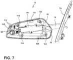
- FIG. 7is a front elevational view of the rearview assembly of FIG. 6 with the electro-optic device removed;
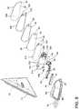
- FIG. 8is a top front exploded perspective view of a rearview assembly of the present disclosure.
- FIG. 9is a rear top exploded perspective view of the rearview assembly of FIG. 8 ;
- FIG. 10is a top perspective view of an electro-optic assembly and imager of the present disclosure.
- FIG. 11is a top plan view of an electro-optic assembly, imager, and turn signal of the present disclosure.
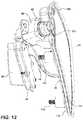
- FIG. 12is a bottom perspective view of the electro-optic assembly, imager, and turn signal of FIG. 11 .
- the terms “upper,” “lower,” “right,” “left,” “rear,” “front,” “vertical,” “horizontal,” and derivatives thereof,shall relate to the disclosure as oriented in FIG. 1 .
- the term “front”shall refer to the surface of the device closer to an intended viewer of the device, and the term “rear” shall refer to the device further from the intended viewer of the device.
- the disclosuremay assume various alternative orientations, except where expressly specified to the contrary.
- the specific devices and processes illustrated in the attached drawings, and described in the following specificationare simply exemplary embodiments of the inventive concepts defined in the appended claims. Hence, specific dimensions and other physical characteristics relating to the embodiments disclosed herein are not to be considered as limiting, unless the claims expressly state otherwise.
- reference numeral 10generally designates a rearview assembly for use with a vehicle 11 that includes a housing 12 having a front 14 defining an opening 16 ( FIGS. 7 and 8 ).
- An external band 20extends laterally about a rear 22 of the housing 12 .
- a turn signal 24is defined in the external band 20 .
- An electro-optic device 30includes a front substrate 32 defining a first surface 34 and a second surface 36 .
- a rear substrate 38defines a third surface 40 and a fourth surface 42 .
- An electro-optic medium 44is disposed between the front substrate 32 and the rear substrate 38 .
- a peripheral seal 46( FIG. 8 ) contains the electro-optic medium 44 between the front substrate 32 and the rear substrate 38 .
- An imager 50is adjacent the electro-optic device 30 .
- a viewing window 52( FIG. 10 ) is disposed on an outboard corner 54 of the electro-optic device 30 .
- the imager 50is in optical communication with the viewing window 52 .
- the rear substrate 38defines a recess 60 ( FIGS. 8 and 9 ) at the viewing window 52 .
- the imager 50receives image data through the front substrate 32 .
- the peripheral seal 46follows at least a portion of a perimeter of the recess 60 . In the illustrated embodiment, the peripheral seal 46 follows edges 62 defined in the rear substrate 38 .
- the housing 12is operably coupled with an elongate arm 70 that may be coupled with a motor 72 .
- the motor 72is configured to move the elongate arm 70 , and consequently, the housing 12 , and the electro-optic device 30 , between deployed and non-deployed positions.
- the elongate arm 70is operably coupled with a base unit 74 that is operably coupled with the vehicle 11 . It will be understood that the elongate arm 70 may be pivotally coupled with the base unit 74 and operable between deployed and retracted positions relative to the vehicle 11 .
- the vehicle 11may be an automobile, off-road vehicle, truck, etc.
- the base unit 74includes a plurality of fasteners 76 ( FIG.
- the elongate arm 70is configured to integrally attach with the housing 12 .
- the external band 20 that extends about a rear of the housing 12is integrally formed with the elongate arm 70 and terminates at a rearward edge 80 of the front substrate 32 .
- the external band 20extends through a bezel 81 , which extends around all or part of the electro-optic device 30 .
- the housing 12also includes an upper cover 82 that may be integral with or formed with the housing 12 .
- the external band 20projects outwardly from the housing 12 to define a rear upper wall 84 and a rear lower wall 86 .
- the rear upper wall 84 and the rear lower wall 86 of the housing 12may be formed from a variety of materials, including aluminum, plastic, carbon fiber, etc.
- the external band 20provides an aperture 90 ( FIG. 7 ) through which the turn signal 24 extends.
- the turn signal 24is configured to activate sequentially when the vehicle 11 is making a turn in the direction of the rearview assembly 10 or when manually selected by the driver.
- the turn signal 24is configured to provide a notification forward of the vehicle 11 that the vehicle 11 is turning and which direction the vehicle 11 is turning.
- the turn signal 24includes a cover 91 that extends over a light source 92 that is configured to emit light into the cover 91 which can be seen externally.
- the light source 92may be one or more incandescent bulbs.
- the light source 92may include a plurality of linearly aligned light emitting diodes, such as light emitting diodes 93 , that can activate in unison or sequentially.
- the rearview assembly 10includes a multitude of internal features configured to aid the driver during operation of the vehicle 11 .
- the electro-optic device 30is configured to dim to minimize glare to a driver during operation of the vehicle 11 .
- the electro-optic medium 44generally functions as a media of variable transmittance, and when electrically energized, darkens and begins to absorb light. The more light the electro-optic medium 44 absorbs, the darker the electro-optic device 30 , and consequently, the rearview assembly 10 , becomes. As a result, the glare associated with bright lights that are reflected toward a driver by the rearview assembly 10 is lessened.
- the electro-optic device 30When the electrical voltage applied to the electro-optic medium 44 is decreased to zero or close to zero, the electro-optic device 30 returns to a clear or almost clear state. It is also contemplated that, in some instances, the electro-optic device 30 could work in reverse where the application of electrical voltage clears the electro-optic device 30 and lessening of the electrical voltage darkens the electro-optic device 30 .
- the electro-optic medium 44is disposed between the front substrate 32 and the rear substrate 38 and sealed between the front substrate 32 and rear substrate 38 by the peripheral seal 46 .
- the electro-optic medium 44may include an electrochromic material, or another electro-optic media having similar qualities may also be used.
- the unitcan also be set to operate automatically.
- circuitrysuch as a printed circuit board (PCB) 94
- PCBprinted circuit board
- the electro-optic medium 44is activated and the rearview assembly 10 begins to dim (reflectance is lowered) in proportion to the amount of glare that is detected by the imager 50 or by a glare sensor operably coupled with the PCB 94 .
- the electro-optic device 30can return to a normal high reflectance state without manual interaction on the part of the driver.
- a conductive layer 100 ( FIG. 9 ) and a conductive layer 102FIG.
- the conductive layer 100 on the front substrate 32is generally transparent, while the conductive layer 102 on the rear substrate 38 may be transparent, or may be semi-transparent or even opaque, and may have reflective characteristics that function as a reflective layer for the electro-optic device 30 .
- the conductive layers 100 , 102 on both the front substrate 32 and the rear substrate 38are operably coupled with electronic circuitry, which is effective to electrically energize the electro-optic medium 44 , thereby switching the transmissivity of the electro-optic device 30 of the rearview assembly 10 .
- J-clips 104may be utilized to provide an electrical connection to the conductors disposed on the front substrate 32 and the rear substrate 38 .
- the rearview assembly 10includes a foam support or adhesive 110 configured to operably couple the fourth surface 42 with a carrier 112 .
- the foam support or adhesive 110defines an aperture 111 that allows optical communication of light sources 113 disposed on an internal support or PCB 115 through the foam support or adhesive 110 .
- the PCB 115is positioned above the imager 50 such that the light sources 113 can emit light through an aperture 117 defined in the carrier 112 , through the aperture 111 , and through the electro-optic device 30 .
- the carrier 112includes a plurality of mechanical fastener mounts 114 to secure the carrier 112 , and consequently, the electro-optic device 30 , to the housing 12 .
- the carrier 112includes robust supports 120 configured to maintain the imager 50 at a particular angle relative to the electro-optic device 30 .
- Cutouts 122provide access for the J-clips 104 to reach the space occupied by the electro-optic medium 44 between the front substrate 32 and the rear substrate 38 .
- the imager 50is configured to collect image data through the front substrate 32 .
- the imager 50is aligned with the recess 60 defined in the rear substrate 38 as well as a recess 123 in the carrier 112 , a recess 124 in the foam support or adhesive 110 , and a recess 125 defined by the peripheral seal 46 .
- the front substrate 32may be at least partially reflective at the viewing window 52 to at least partially conceal the imager 50 .
- the electro-optic device 30also includes a graphic 130 .
- the graphic 130may be a reflective ring or chrome ring and may extend about a periphery of the viewing window 52 .
- the graphic 130may be disposed proximate the periphery of the electro-optic device 30 .
- the graphic 130may be disposed anywhere within the stack of the electro-optic device 30 or elsewhere. In the illustrated embodiment, the graphic 130 is located proximate the second surface 36 .
- the graphic 130could also be etched using chemicals, lasers, mechanical devices, etc., into one or more surfaces of the front and rear substrates 32 , 38 .
- the graphic 130may define an opening 132 that is in optical communication with the window 52 and which provides a viewing area to the imager 50 .
- the graphic 130could also include etched indicia 134 that may function to communicate information to a driver.
- the indicia 134may function as a blind spot indicator, turn signal indicator, etc., which may be illuminated by the light sources 113 supported on PCB 115 ( FIG. 7 ). Accordingly, it is contemplated that the indicia 134 , when illuminated, will be visible by a driver of the vehicle 11 or by a following vehicle.
- the indicia 134could also be used as a decoration and include coloration that generally matches a decorative pattern of the vehicle 11 . In the illustrated embodiment of FIGS.
- the seal 46generally follows inside edges of the recess 60 .
- the seal 46follows an outer perimeter of the rear substrate 38 and not an outer perimeter of the front substrate 32 . It will be understood by a person having ordinary skill in the art that this configuration could vary.
- the electro-optic device 30is configured for use with the imager 50 and the PCB 94 .
- the PCB 94is operably coupled with the turn signal 24 , as well as the imager 50 , and configured to provide operating instructions for both.
- the PCB 94 , the imager 50 , and the electro-optic device 30may be electrically coupled via a ribbon connector or wiring 140 or via another suitable method.
- the imager 50is disposed behind the electro-optic device 30 and is set at an angle relative to the electro-optic device 30 , as shown in FIGS. 11 and 12 .
- the imager 50is in close proximity to the second surface 36 of the front substrate 32 .
- the imager 50receives image data through the viewing window 52 at the recess 60 defined in the rear substrate 38 . Accordingly, the imager 50 can be positioned very close to the second surface 36 of the front substrate 32 , an area that would otherwise be occupied by the rear substrate 38 . Moreover, because the imager 50 is disposed at an outboard corner of the rearview assembly 10 as a whole, an even better viewing angle can be maintained. As illustrated, the PCB 94 is disposed directly in front of the turn signal 24 and may be in abutting contact therewith. Additionally, the PCB 94 may be mechanically fastened with the turn signal 24 . The angle of the imager 50 is maintained by supports that extend around the viewing window 52 .
- the imager 50is generally configured to capture image data and includes a field of view that covers a blind spot zone of the vehicle 11 .
- mechanical fastenersare disposed on a rear portion of the carrier 112 , and are configured to secure the rear portion of the carrier 112 with the housing 12 .
- the rearview assembly as set forth hereinprovides a robust construction capable of movement between deployed and retracted positions.
- the rearview assemblyalso includes a PCB that may control a forward turn signal light, a blind spot indicator, and an imager that collects image data rearward of the vehicle.
- the imagermay be operably coupled with the PCB and the blind spot indicator such that when a following vehicle is present in the blind spot of the vehicle, the PCB can activate light sources of the blind spot indicator to inform the driver of the vehicle.
- the external bandprovides an aesthetically pleasing feature around the housing, and also provides additional protection to the remainder of the housing and the components disposed within the housing.
- the rearview assembly set forth hereinis an improvement over traditional constructions and provides useful safety features that minimize the likelihood of a collision event during travel.
- the term “coupled”in all of its forms, couple, coupling, coupled, etc. generally means the joining of two components (electrical or mechanical) directly or indirectly to one another. Such joining may be stationary in nature or movable in nature. Such joining may be achieved with the two components (electrical or mechanical) and any additional intermediate members being integrally formed as a single unitary body with one another or with the two components. Such joining may be permanent in nature or may be removable or releasable in nature unless otherwise stated.
- elements shown as integrally formedmay be constructed of multiple parts, or elements shown as multiple parts may be integrally formed, the operation of the interfaces may be reversed or otherwise varied, the length or width of the structures and/or members or connector or other elements of the system may be varied, the nature or number of adjustment positions provided between the elements may be varied.
- the elements and/or assemblies of the systemmay be constructed from any of a wide variety of materials that provide sufficient strength or durability, in any of a wide variety of colors, textures, and combinations. Accordingly, all such modifications are intended to be included within the scope of the present innovations. Other substitutions, modifications, changes, and omissions may be made in the design, operating conditions, and arrangement of the desired and other exemplary embodiments without departing from the spirit of the present innovations.
Landscapes
- Engineering & Computer Science (AREA)
- Physics & Mathematics (AREA)
- Mechanical Engineering (AREA)
- Nonlinear Science (AREA)
- Multimedia (AREA)
- General Physics & Mathematics (AREA)
- Optics & Photonics (AREA)
- Chemical & Material Sciences (AREA)
- Crystallography & Structural Chemistry (AREA)
- Signal Processing (AREA)
- Combustion & Propulsion (AREA)
- Transportation (AREA)
- Electrochromic Elements, Electrophoresis, Or Variable Reflection Or Absorption Elements (AREA)
- Rear-View Mirror Devices That Are Mounted On The Exterior Of The Vehicle (AREA)
- Devices For Indicating Variable Information By Combining Individual Elements (AREA)
- Fittings On The Vehicle Exterior For Carrying Loads, And Devices For Holding Or Mounting Articles (AREA)
Abstract
Description
Claims (20)
Priority Applications (1)
| Application Number | Priority Date | Filing Date | Title |
|---|---|---|---|
| US15/858,563US10730436B2 (en) | 2016-12-30 | 2017-12-29 | Vehicular outside rearview assembly |
Applications Claiming Priority (2)
| Application Number | Priority Date | Filing Date | Title |
|---|---|---|---|
| US201662441016P | 2016-12-30 | 2016-12-30 | |
| US15/858,563US10730436B2 (en) | 2016-12-30 | 2017-12-29 | Vehicular outside rearview assembly |
Publications (2)
| Publication Number | Publication Date |
|---|---|
| US20180186292A1 US20180186292A1 (en) | 2018-07-05 |
| US10730436B2true US10730436B2 (en) | 2020-08-04 |
Family
ID=62709309
Family Applications (1)
| Application Number | Title | Priority Date | Filing Date |
|---|---|---|---|
| US15/858,563ActiveUS10730436B2 (en) | 2016-12-30 | 2017-12-29 | Vehicular outside rearview assembly |
Country Status (6)
| Country | Link |
|---|---|
| US (1) | US10730436B2 (en) |
| EP (1) | EP3562709B1 (en) |
| JP (1) | JP6918944B2 (en) |
| KR (1) | KR102438097B1 (en) |
| CN (1) | CN110023143A (en) |
| WO (1) | WO2018126164A1 (en) |
Cited By (1)
| Publication number | Priority date | Publication date | Assignee | Title |
|---|---|---|---|---|
| US12257952B2 (en) | 2021-07-15 | 2025-03-25 | Gentex Corporation | Rearview assembly |
Families Citing this family (7)
| Publication number | Priority date | Publication date | Assignee | Title |
|---|---|---|---|---|
| JP6918944B2 (en)* | 2016-12-30 | 2021-08-11 | ジェンテックス コーポレイション | External rearview mirror assembly for vehicles |
| USD860086S1 (en)* | 2017-03-01 | 2019-09-17 | Dr. Ing. H.C. F. Porsche Aktiengesellschaft | Side view mirror for motor vehicle |
| JP7345045B2 (en)* | 2019-07-25 | 2023-09-14 | ジェンテックス コーポレイション | Segmented variation controlled electro-optic element |
| US20210031689A1 (en) | 2019-07-31 | 2021-02-04 | Ficosa North America Corporation | Exterior rearview mirror or winglet for a vehicle having a lighting lens assembly attached to a housing |
| US11724648B2 (en)* | 2019-09-23 | 2023-08-15 | Super Atv Llc | Modular vehicle mirror assembly |
| EP4051539B1 (en)* | 2019-10-31 | 2023-10-18 | Gentex Corporation | Rotatable outside mirror with imager assembly |
| TWI852486B (en)* | 2023-04-20 | 2024-08-11 | 群光電子股份有限公司 | Vehicle image recognition module |
Citations (56)
| Publication number | Priority date | Publication date | Assignee | Title |
|---|---|---|---|---|
| US4798967A (en) | 1988-03-24 | 1989-01-17 | Murakami Kaimeido Co | Control system for foldable outside rearview mirror |
| US5557476A (en) | 1991-06-17 | 1996-09-17 | Eiji Murakami | Foldable outside rearview mirror |
| US5669705A (en) | 1993-02-01 | 1997-09-23 | Donnelly Corporation | Exterior vehicle mirror system including signal light |
| WO1998044386A1 (en) | 1997-04-02 | 1998-10-08 | Gentex Corporation | An electrochromic mirror with two thin glass elements and a gelled electrochromic medium |
| US5923457A (en) | 1997-04-02 | 1999-07-13 | Gentex Corporation | Electro-optic device including a low sheet resistance, high transmission transparent electrode |
| US6195194B1 (en) | 1999-03-16 | 2001-02-27 | Gentex Corporation | Lightweight electrochromic mirror |
| US6244716B1 (en) | 1999-05-17 | 2001-06-12 | Gentex Corporation | Exterior mirror sub-assembly with combined electronic circuitry and mirror element |
| WO2001064481A2 (en) | 2000-03-02 | 2001-09-07 | Donnelly Corporation | Video mirror systems incorporating an accessory module |
| US6630888B2 (en) | 1999-01-22 | 2003-10-07 | Lang-Mekra North America, Llc | Rearview mirror assembly with integral display element and camera |
| US20050232469A1 (en)* | 2004-04-15 | 2005-10-20 | Kenneth Schofield | Imaging system for vehicle |
| US20060106518A1 (en)* | 2004-11-18 | 2006-05-18 | Gentex Corporation | Image acquisition and processing systems for vehicle equipment control |
| US7195381B2 (en)* | 2001-01-23 | 2007-03-27 | Donnelly Corporation | Vehicle interior LED lighting system |
| US7324261B2 (en) | 1999-07-09 | 2008-01-29 | Gentex Corporation | Electrochromic devices with thin bezel-covered edge |
| US20090243824A1 (en)* | 2008-03-31 | 2009-10-01 | Magna Mirrors Of America, Inc. | Interior rearview mirror system |
| US20100253543A1 (en)* | 2009-04-02 | 2010-10-07 | Gm Global Technology Operations, Inc. | Rear parking assist on full rear-window head-up display |
| US20100253539A1 (en)* | 2009-04-02 | 2010-10-07 | Gm Global Technology Operations, Inc. | Vehicle-to-vehicle communicator on full-windshield head-up display |
| US20100253594A1 (en)* | 2009-04-02 | 2010-10-07 | Gm Global Technology Operations, Inc. | Peripheral salient feature enhancement on full-windshield head-up display |
| US20100253493A1 (en)* | 2009-04-02 | 2010-10-07 | Gm Global Technology Operations, Inc. | Recommended following distance on full-windshield head-up display |
| US20100253599A1 (en)* | 2009-04-02 | 2010-10-07 | Gm Global Technology Operations, Inc. | Luminance uniformity compensation of vector projection display |
| US20100254019A1 (en)* | 2009-04-02 | 2010-10-07 | Gm Global Technology Operations, Inc. | Uv laser beamlett on full-windshield head-up display |
| US20100253489A1 (en)* | 2009-04-02 | 2010-10-07 | Gm Global Technology Operations, Inc. | Distortion and perspective correction of vector projection display |
| US20100253542A1 (en)* | 2009-04-02 | 2010-10-07 | Gm Global Technology Operations, Inc. | Point of interest location marking on full windshield head-up display |
| US20100253602A1 (en)* | 2009-04-02 | 2010-10-07 | Gm Global Technology Operations, Inc. | Dynamic vehicle system information on full windshield head-up display |
| US20100253593A1 (en)* | 2009-04-02 | 2010-10-07 | Gm Global Technology Operations, Inc. | Enhanced vision system full-windshield hud |
| US20100253600A1 (en)* | 2009-04-02 | 2010-10-07 | Gm Global Technology Operations, Inc. | Full-windshield head-up display enhancement: anti-reflective glass hard coat |
| US20100253688A1 (en)* | 2009-04-02 | 2010-10-07 | Gm Global Technology Operations, Inc. | Scan loop optimization of vector projection display |
| US20100253541A1 (en)* | 2009-04-02 | 2010-10-07 | Gm Global Technology Operations, Inc. | Traffic infrastructure indicator on head-up display |
| US20100253598A1 (en)* | 2009-04-02 | 2010-10-07 | Gm Global Technology Operations, Inc. | Lane of travel on windshield head-up display |
| US20100253595A1 (en)* | 2009-04-02 | 2010-10-07 | Gm Global Technology Operations, Inc. | Virtual controls and displays by laser projection |
| US20100253596A1 (en)* | 2009-04-02 | 2010-10-07 | Gm Global Technology Operations, Inc. | Continuation of exterior view on interior pillars and surfaces |
| US20100253601A1 (en)* | 2009-04-02 | 2010-10-07 | Gm Global Technology Operations, Inc. | Full-windshield hud enhancement: pixelated field of view limited architecture |
| US20100253526A1 (en)* | 2009-04-02 | 2010-10-07 | Gm Global Technology Operations, Inc. | Driver drowsy alert on full-windshield head-up display |
| US20100253492A1 (en)* | 2009-04-02 | 2010-10-07 | Gm Global Technology Operations, Inc. | Daytime pedestrian detection on full-windscreen head-up display |
| US20100253540A1 (en)* | 2009-04-02 | 2010-10-07 | Gm Global Technology Operations, Inc. | Enhanced road vision on full windshield head-up display |
| US20100253597A1 (en)* | 2009-04-02 | 2010-10-07 | Gm Global Technology Operations, Inc. | Rear view mirror on full-windshield head-up display |
| US20100253918A1 (en)* | 2009-04-02 | 2010-10-07 | Gm Global Technology Operations, Inc. | Infotainment display on full-windshield head-up display |
| US7821696B2 (en)* | 1997-04-02 | 2010-10-26 | Gentex Corporation | Electrochromic rearview mirror assembly incorporating a display/signal light |
| US20100292886A1 (en)* | 2009-05-18 | 2010-11-18 | Gm Global Technology Operations, Inc. | Turn by turn graphical navigation on full windshield head-up display |
| US20100289632A1 (en)* | 2009-05-18 | 2010-11-18 | Gm Global Technology Operations, Inc. | Night vision on full windshield head-up display |
| US7937667B2 (en)* | 2006-09-27 | 2011-05-03 | Donnelly Corporation | Multimedia mirror assembly for vehicle |
| KR20120009153A (en) | 2010-07-22 | 2012-02-01 | 강용주 | Rear view mirror with electronic camera at the end |
| US20120072080A1 (en)* | 2004-11-18 | 2012-03-22 | Oliver Jeromin | Image acquisition and processing system for vehicle equipment control |
| US8366284B2 (en) | 2008-08-05 | 2013-02-05 | Smr Patents S.A.R.L. | Vehicle mirror power fold mechanism |
| US20140015972A1 (en) | 2012-07-11 | 2014-01-16 | Gentex Corporation | Stand alone blind spot detection system |
| US8976247B1 (en)* | 2004-09-14 | 2015-03-10 | Magna Electronics Inc. | Rear vision system for a vehicle |
| US9019090B2 (en)* | 2000-03-02 | 2015-04-28 | Magna Electronics Inc. | Vision system for vehicle |
| US9057875B2 (en) | 2012-04-24 | 2015-06-16 | Gentex Corporation | Display mirror assembly |
| CN104742807A (en) | 2015-04-15 | 2015-07-01 | 宁波精成车业有限公司 | Intelligent external rearview mirror |
| US9073491B2 (en)* | 2002-09-20 | 2015-07-07 | Donnelly Corporation | Exterior rearview mirror assembly |
| CN204472689U (en) | 2014-12-31 | 2015-07-15 | 北京汽车研究总院有限公司 | A kind of vehicle with safe avoidance back mirror |
| US20150224934A1 (en) | 2006-10-24 | 2015-08-13 | Magna Mirrors Of America, Inc. | Exterior mirror reflective element sub-assembly |
| US20150232028A1 (en) | 2014-02-14 | 2015-08-20 | Magnadyne Corporation | Exterior Mirror Blind Spot Warning Display and Video Camera |
| JP2016030495A (en) | 2014-07-28 | 2016-03-07 | 株式会社村上開明堂 | Outer mirror for vehicle with lamp |
| US20180056871A1 (en)* | 2002-08-21 | 2018-03-01 | Magna Electronics Inc. | Multi-camera vision system for a vehicle |
| US20180170265A1 (en) | 2016-12-16 | 2018-06-21 | Gentex Corporation | Fold-in outside display mirror |
| US20180186292A1 (en)* | 2016-12-30 | 2018-07-05 | Gentex Corporation | Vehicular outside rearview assembly |
Family Cites Families (11)
| Publication number | Priority date | Publication date | Assignee | Title |
|---|---|---|---|---|
| US5877897A (en)* | 1993-02-26 | 1999-03-02 | Donnelly Corporation | Automatic rearview mirror, vehicle lighting control and vehicle interior monitoring system using a photosensor array |
| CA2290182A1 (en)* | 1999-01-22 | 2000-07-22 | Lang-Mekra North America, Llc | Rearview mirror, with camera |
| DE19903595A1 (en)* | 1999-01-22 | 2000-08-24 | Mekra Lang Gmbh & Co Kg | Rearview mirror |
| CN100565315C (en)* | 2003-05-06 | 2009-12-02 | 金泰克斯公司 | Electro-optic rearview mirror element |
| JP4979376B2 (en)* | 2003-05-06 | 2012-07-18 | ジェンテックス コーポレイション | Vehicle rearview mirror elements and assemblies incorporating these elements |
| WO2008051910A2 (en)* | 2006-10-24 | 2008-05-02 | Donnelly Corporation | Display device for exterior mirror |
| KR101316408B1 (en)* | 2006-08-29 | 2013-10-08 | 엘지이노텍 주식회사 | Detection monitoring apparatus and method |
| KR101118533B1 (en)* | 2009-09-28 | 2012-03-12 | 서울대학교산학협력단 | composite film for light emitting apparatus, light emitting apparatus and method for fabricating the same |
| JP2016035521A (en)* | 2014-08-04 | 2016-03-17 | 株式会社村上開明堂 | Solid type ec mirror for vehicle |
| JP3201688U (en)* | 2015-10-09 | 2015-12-24 | 群淵 林 | Door mirror device |
| CN205615414U (en)* | 2016-03-24 | 2016-10-05 | 王�琦 | Wide angle formula car reflector |
- 2017
- 2017-12-29JPJP2019534810Apatent/JP6918944B2/enactiveActive
- 2017-12-29KRKR1020197015988Apatent/KR102438097B1/enactiveActive
- 2017-12-29CNCN201780070960.7Apatent/CN110023143A/enactivePending
- 2017-12-29EPEP17886021.9Apatent/EP3562709B1/enactiveActive
- 2017-12-29WOPCT/US2017/069000patent/WO2018126164A1/ennot_activeCeased
- 2017-12-29USUS15/858,563patent/US10730436B2/enactiveActive
Patent Citations (58)
| Publication number | Priority date | Publication date | Assignee | Title |
|---|---|---|---|---|
| US4798967A (en) | 1988-03-24 | 1989-01-17 | Murakami Kaimeido Co | Control system for foldable outside rearview mirror |
| US5557476A (en) | 1991-06-17 | 1996-09-17 | Eiji Murakami | Foldable outside rearview mirror |
| US5669705A (en) | 1993-02-01 | 1997-09-23 | Donnelly Corporation | Exterior vehicle mirror system including signal light |
| US7821696B2 (en)* | 1997-04-02 | 2010-10-26 | Gentex Corporation | Electrochromic rearview mirror assembly incorporating a display/signal light |
| WO1998044386A1 (en) | 1997-04-02 | 1998-10-08 | Gentex Corporation | An electrochromic mirror with two thin glass elements and a gelled electrochromic medium |
| US5923457A (en) | 1997-04-02 | 1999-07-13 | Gentex Corporation | Electro-optic device including a low sheet resistance, high transmission transparent electrode |
| US6630888B2 (en) | 1999-01-22 | 2003-10-07 | Lang-Mekra North America, Llc | Rearview mirror assembly with integral display element and camera |
| US6195194B1 (en) | 1999-03-16 | 2001-02-27 | Gentex Corporation | Lightweight electrochromic mirror |
| US6244716B1 (en) | 1999-05-17 | 2001-06-12 | Gentex Corporation | Exterior mirror sub-assembly with combined electronic circuitry and mirror element |
| US7324261B2 (en) | 1999-07-09 | 2008-01-29 | Gentex Corporation | Electrochromic devices with thin bezel-covered edge |
| US9019090B2 (en)* | 2000-03-02 | 2015-04-28 | Magna Electronics Inc. | Vision system for vehicle |
| WO2001064481A2 (en) | 2000-03-02 | 2001-09-07 | Donnelly Corporation | Video mirror systems incorporating an accessory module |
| US7195381B2 (en)* | 2001-01-23 | 2007-03-27 | Donnelly Corporation | Vehicle interior LED lighting system |
| US20180056871A1 (en)* | 2002-08-21 | 2018-03-01 | Magna Electronics Inc. | Multi-camera vision system for a vehicle |
| US9073491B2 (en)* | 2002-09-20 | 2015-07-07 | Donnelly Corporation | Exterior rearview mirror assembly |
| US20190273896A1 (en)* | 2004-04-15 | 2019-09-05 | Magna Electronics Inc. | Vehicular control system |
| US20050232469A1 (en)* | 2004-04-15 | 2005-10-20 | Kenneth Schofield | Imaging system for vehicle |
| US20190283673A1 (en)* | 2004-09-14 | 2019-09-19 | Magna Electronics Inc. | Rear backup system for a vehicle |
| US8976247B1 (en)* | 2004-09-14 | 2015-03-10 | Magna Electronics Inc. | Rear vision system for a vehicle |
| US20060106518A1 (en)* | 2004-11-18 | 2006-05-18 | Gentex Corporation | Image acquisition and processing systems for vehicle equipment control |
| US20120072080A1 (en)* | 2004-11-18 | 2012-03-22 | Oliver Jeromin | Image acquisition and processing system for vehicle equipment control |
| US7937667B2 (en)* | 2006-09-27 | 2011-05-03 | Donnelly Corporation | Multimedia mirror assembly for vehicle |
| US20150224934A1 (en) | 2006-10-24 | 2015-08-13 | Magna Mirrors Of America, Inc. | Exterior mirror reflective element sub-assembly |
| US20090243824A1 (en)* | 2008-03-31 | 2009-10-01 | Magna Mirrors Of America, Inc. | Interior rearview mirror system |
| US8366284B2 (en) | 2008-08-05 | 2013-02-05 | Smr Patents S.A.R.L. | Vehicle mirror power fold mechanism |
| US20100253543A1 (en)* | 2009-04-02 | 2010-10-07 | Gm Global Technology Operations, Inc. | Rear parking assist on full rear-window head-up display |
| US20100253602A1 (en)* | 2009-04-02 | 2010-10-07 | Gm Global Technology Operations, Inc. | Dynamic vehicle system information on full windshield head-up display |
| US20100253598A1 (en)* | 2009-04-02 | 2010-10-07 | Gm Global Technology Operations, Inc. | Lane of travel on windshield head-up display |
| US20100253595A1 (en)* | 2009-04-02 | 2010-10-07 | Gm Global Technology Operations, Inc. | Virtual controls and displays by laser projection |
| US20100253596A1 (en)* | 2009-04-02 | 2010-10-07 | Gm Global Technology Operations, Inc. | Continuation of exterior view on interior pillars and surfaces |
| US20100253601A1 (en)* | 2009-04-02 | 2010-10-07 | Gm Global Technology Operations, Inc. | Full-windshield hud enhancement: pixelated field of view limited architecture |
| US20100253526A1 (en)* | 2009-04-02 | 2010-10-07 | Gm Global Technology Operations, Inc. | Driver drowsy alert on full-windshield head-up display |
| US20100253492A1 (en)* | 2009-04-02 | 2010-10-07 | Gm Global Technology Operations, Inc. | Daytime pedestrian detection on full-windscreen head-up display |
| US20100253540A1 (en)* | 2009-04-02 | 2010-10-07 | Gm Global Technology Operations, Inc. | Enhanced road vision on full windshield head-up display |
| US20100253597A1 (en)* | 2009-04-02 | 2010-10-07 | Gm Global Technology Operations, Inc. | Rear view mirror on full-windshield head-up display |
| US20100253918A1 (en)* | 2009-04-02 | 2010-10-07 | Gm Global Technology Operations, Inc. | Infotainment display on full-windshield head-up display |
| US20100253688A1 (en)* | 2009-04-02 | 2010-10-07 | Gm Global Technology Operations, Inc. | Scan loop optimization of vector projection display |
| US20100253539A1 (en)* | 2009-04-02 | 2010-10-07 | Gm Global Technology Operations, Inc. | Vehicle-to-vehicle communicator on full-windshield head-up display |
| US20100253594A1 (en)* | 2009-04-02 | 2010-10-07 | Gm Global Technology Operations, Inc. | Peripheral salient feature enhancement on full-windshield head-up display |
| US20100253600A1 (en)* | 2009-04-02 | 2010-10-07 | Gm Global Technology Operations, Inc. | Full-windshield head-up display enhancement: anti-reflective glass hard coat |
| US20100253493A1 (en)* | 2009-04-02 | 2010-10-07 | Gm Global Technology Operations, Inc. | Recommended following distance on full-windshield head-up display |
| US20100253593A1 (en)* | 2009-04-02 | 2010-10-07 | Gm Global Technology Operations, Inc. | Enhanced vision system full-windshield hud |
| US20100253541A1 (en)* | 2009-04-02 | 2010-10-07 | Gm Global Technology Operations, Inc. | Traffic infrastructure indicator on head-up display |
| US20100253599A1 (en)* | 2009-04-02 | 2010-10-07 | Gm Global Technology Operations, Inc. | Luminance uniformity compensation of vector projection display |
| US20100253542A1 (en)* | 2009-04-02 | 2010-10-07 | Gm Global Technology Operations, Inc. | Point of interest location marking on full windshield head-up display |
| US20100253489A1 (en)* | 2009-04-02 | 2010-10-07 | Gm Global Technology Operations, Inc. | Distortion and perspective correction of vector projection display |
| US20100254019A1 (en)* | 2009-04-02 | 2010-10-07 | Gm Global Technology Operations, Inc. | Uv laser beamlett on full-windshield head-up display |
| US20100289632A1 (en)* | 2009-05-18 | 2010-11-18 | Gm Global Technology Operations, Inc. | Night vision on full windshield head-up display |
| US20100292886A1 (en)* | 2009-05-18 | 2010-11-18 | Gm Global Technology Operations, Inc. | Turn by turn graphical navigation on full windshield head-up display |
| KR20120009153A (en) | 2010-07-22 | 2012-02-01 | 강용주 | Rear view mirror with electronic camera at the end |
| US9057875B2 (en) | 2012-04-24 | 2015-06-16 | Gentex Corporation | Display mirror assembly |
| US20140015972A1 (en) | 2012-07-11 | 2014-01-16 | Gentex Corporation | Stand alone blind spot detection system |
| US20150232028A1 (en) | 2014-02-14 | 2015-08-20 | Magnadyne Corporation | Exterior Mirror Blind Spot Warning Display and Video Camera |
| JP2016030495A (en) | 2014-07-28 | 2016-03-07 | 株式会社村上開明堂 | Outer mirror for vehicle with lamp |
| CN204472689U (en) | 2014-12-31 | 2015-07-15 | 北京汽车研究总院有限公司 | A kind of vehicle with safe avoidance back mirror |
| CN104742807A (en) | 2015-04-15 | 2015-07-01 | 宁波精成车业有限公司 | Intelligent external rearview mirror |
| US20180170265A1 (en) | 2016-12-16 | 2018-06-21 | Gentex Corporation | Fold-in outside display mirror |
| US20180186292A1 (en)* | 2016-12-30 | 2018-07-05 | Gentex Corporation | Vehicular outside rearview assembly |
Non-Patent Citations (1)
| Title |
|---|
| Extended European Search Report dated Sep. 11, 2019, for corresponding European application No. 17886021.9, 6 pages. |
Cited By (1)
| Publication number | Priority date | Publication date | Assignee | Title |
|---|---|---|---|---|
| US12257952B2 (en) | 2021-07-15 | 2025-03-25 | Gentex Corporation | Rearview assembly |
Also Published As
| Publication number | Publication date |
|---|---|
| EP3562709B1 (en) | 2021-05-19 |
| KR102438097B1 (en) | 2022-08-31 |
| JP6918944B2 (en) | 2021-08-11 |
| US20180186292A1 (en) | 2018-07-05 |
| CN110023143A (en) | 2019-07-16 |
| WO2018126164A1 (en) | 2018-07-05 |
| JP2020514159A (en) | 2020-05-21 |
| EP3562709A4 (en) | 2019-11-06 |
| KR20190104992A (en) | 2019-09-11 |
| EP3562709A1 (en) | 2019-11-06 |
Similar Documents
| Publication | Publication Date | Title |
|---|---|---|
| US10730436B2 (en) | Vehicular outside rearview assembly | |
| US20220402431A1 (en) | Interior trim part of motor vehicle with thin-film display device | |
| US10589686B2 (en) | Vehicle exterior rearview mirror system having an indicator | |
| DE69917821T2 (en) | Rearview mirror arrangement with vehicle information display | |
| JP3868742B2 (en) | Electrochromic mirror with third surface reflector | |
| US7690824B2 (en) | Mirror assembly for vehicle | |
| US9598016B2 (en) | Interior rearview mirror assembly | |
| US6170956B1 (en) | Rearview mirror with display | |
| US9580019B2 (en) | Interior rearview mirror assembly with user input module | |
| US6420800B1 (en) | Rearview mirror with buttons incorporating display | |
| US10131279B2 (en) | Display mirror assembly with an RF shield bezel | |
| US10071689B2 (en) | Rearview mirror system with a display | |
| US11242009B2 (en) | Vehicular exterior mirror system with blind spot indicator | |
| US11827155B2 (en) | Vehicular exterior rearview mirror assembly with blind spot indicator | |
| US8926149B2 (en) | Side-view mirror assembly with selectively illuminating portion | |
| CN113002415A (en) | Lighting device for a motor vehicle and motor vehicle | |
| US10451837B2 (en) | Inductive power connection/data transfer for electro-optic mirror |
Legal Events
| Date | Code | Title | Description |
|---|---|---|---|
| FEPP | Fee payment procedure | Free format text:ENTITY STATUS SET TO UNDISCOUNTED (ORIGINAL EVENT CODE: BIG.); ENTITY STATUS OF PATENT OWNER: LARGE ENTITY | |
| AS | Assignment | Owner name:GENTEX CORPORATION, MICHIGAN Free format text:ASSIGNMENT OF ASSIGNORS INTEREST;ASSIGNORS:HAMLIN, BRADLEY R.;LOCK, NIGEL T.;REEL/FRAME:044604/0776 Effective date:20180103 | |
| STPP | Information on status: patent application and granting procedure in general | Free format text:DOCKETED NEW CASE - READY FOR EXAMINATION | |
| STPP | Information on status: patent application and granting procedure in general | Free format text:NON FINAL ACTION MAILED | |
| STPP | Information on status: patent application and granting procedure in general | Free format text:RESPONSE TO NON-FINAL OFFICE ACTION ENTERED AND FORWARDED TO EXAMINER | |
| STPP | Information on status: patent application and granting procedure in general | Free format text:FINAL REJECTION MAILED | |
| STPP | Information on status: patent application and granting procedure in general | Free format text:ADVISORY ACTION MAILED | |
| STPP | Information on status: patent application and granting procedure in general | Free format text:NON FINAL ACTION MAILED | |
| STPP | Information on status: patent application and granting procedure in general | Free format text:RESPONSE TO NON-FINAL OFFICE ACTION ENTERED AND FORWARDED TO EXAMINER | |
| STPP | Information on status: patent application and granting procedure in general | Free format text:NOTICE OF ALLOWANCE MAILED -- APPLICATION RECEIVED IN OFFICE OF PUBLICATIONS | |
| STPP | Information on status: patent application and granting procedure in general | Free format text:PUBLICATIONS -- ISSUE FEE PAYMENT VERIFIED | |
| STCF | Information on status: patent grant | Free format text:PATENTED CASE | |
| MAFP | Maintenance fee payment | Free format text:PAYMENT OF MAINTENANCE FEE, 4TH YEAR, LARGE ENTITY (ORIGINAL EVENT CODE: M1551); ENTITY STATUS OF PATENT OWNER: LARGE ENTITY Year of fee payment:4 |