US10729473B2 - System for fixing cervical vertebrae and a driver used for an apparatus for fixing cervical vertebrae - Google Patents
System for fixing cervical vertebrae and a driver used for an apparatus for fixing cervical vertebraeDownload PDFInfo
- Publication number
- US10729473B2 US10729473B2US14/938,286US201514938286AUS10729473B2US 10729473 B2US10729473 B2US 10729473B2US 201514938286 AUS201514938286 AUS 201514938286AUS 10729473 B2US10729473 B2US 10729473B2
- Authority
- US
- United States
- Prior art keywords
- screw
- cervical vertebrae
- driver
- convex portion
- end portion
- Prior art date
- Legal status (The legal status is an assumption and is not a legal conclusion. Google has not performed a legal analysis and makes no representation as to the accuracy of the status listed.)
- Active, expires
Links
- 239000002184metalSubstances0.000claimsdescription2
- 230000007480spreadingEffects0.000abstractdescription4
- 238000003780insertionMethods0.000description8
- 230000037431insertionEffects0.000description8
- 238000000034methodMethods0.000description8
- 239000007943implantSubstances0.000description7
- 230000008569processEffects0.000description7
- 230000003902lesionEffects0.000description3
- 210000005036nerveAnatomy0.000description3
- 230000008901benefitEffects0.000description2
- 210000004556brainAnatomy0.000description2
- 238000012986modificationMethods0.000description2
- 230000004048modificationEffects0.000description2
- 230000001953sensory effectEffects0.000description2
- 206010028570MyelopathyDiseases0.000description1
- 206010028980NeoplasmDiseases0.000description1
- 206010033799ParalysisDiseases0.000description1
- 206010041591Spinal osteoarthritisDiseases0.000description1
- 210000001367arteryAnatomy0.000description1
- 210000000467autonomic pathwayAnatomy0.000description1
- 239000008280bloodSubstances0.000description1
- 210000004369bloodAnatomy0.000description1
- 210000000988bone and boneAnatomy0.000description1
- 210000004720cerebrumAnatomy0.000description1
- 208000036319cervical spondylosisDiseases0.000description1
- 230000001079digestive effectEffects0.000description1
- 201000010099diseaseDiseases0.000description1
- 208000037265diseases, disorders, signs and symptomsDiseases0.000description1
- 238000010348incorporationMethods0.000description1
- 210000000056organAnatomy0.000description1
- 230000029058respiratory gaseous exchangeEffects0.000description1
- 238000000926separation methodMethods0.000description1
- 210000003625skullAnatomy0.000description1
- 210000000278spinal cordAnatomy0.000description1
- 208000005801spondylosisDiseases0.000description1
- 230000002889sympathetic effectEffects0.000description1
- 208000024891symptomDiseases0.000description1
- 210000003462veinAnatomy0.000description1
- 210000002385vertebral arteryAnatomy0.000description1
Images

Classifications
- A—HUMAN NECESSITIES
- A61—MEDICAL OR VETERINARY SCIENCE; HYGIENE
- A61B—DIAGNOSIS; SURGERY; IDENTIFICATION
- A61B17/00—Surgical instruments, devices or methods
- A61B17/56—Surgical instruments or methods for treatment of bones or joints; Devices specially adapted therefor
- A61B17/58—Surgical instruments or methods for treatment of bones or joints; Devices specially adapted therefor for osteosynthesis, e.g. bone plates, screws or setting implements
- A61B17/88—Osteosynthesis instruments; Methods or means for implanting or extracting internal or external fixation devices
- A61B17/92—Impactors or extractors, e.g. for removing intramedullary devices
- A—HUMAN NECESSITIES
- A61—MEDICAL OR VETERINARY SCIENCE; HYGIENE
- A61B—DIAGNOSIS; SURGERY; IDENTIFICATION
- A61B17/00—Surgical instruments, devices or methods
- A61B17/56—Surgical instruments or methods for treatment of bones or joints; Devices specially adapted therefor
- A61B17/58—Surgical instruments or methods for treatment of bones or joints; Devices specially adapted therefor for osteosynthesis, e.g. bone plates, screws or setting implements
- A61B17/68—Internal fixation devices, including fasteners and spinal fixators, even if a part thereof projects from the skin
- A61B17/70—Spinal positioners or stabilisers, e.g. stabilisers comprising fluid filler in an implant
- A61B17/7059—Cortical plates
- A—HUMAN NECESSITIES
- A61—MEDICAL OR VETERINARY SCIENCE; HYGIENE
- A61B—DIAGNOSIS; SURGERY; IDENTIFICATION
- A61B17/00—Surgical instruments, devices or methods
- A61B17/56—Surgical instruments or methods for treatment of bones or joints; Devices specially adapted therefor
- A61B17/58—Surgical instruments or methods for treatment of bones or joints; Devices specially adapted therefor for osteosynthesis, e.g. bone plates, screws or setting implements
- A61B17/68—Internal fixation devices, including fasteners and spinal fixators, even if a part thereof projects from the skin
- A61B17/70—Spinal positioners or stabilisers, e.g. stabilisers comprising fluid filler in an implant
- A61B17/7074—Tools specially adapted for spinal fixation operations other than for bone removal or filler handling
- A61B17/7076—Tools specially adapted for spinal fixation operations other than for bone removal or filler handling for driving, positioning or assembling spinal clamps or bone anchors specially adapted for spinal fixation
- A61B17/7082—Tools specially adapted for spinal fixation operations other than for bone removal or filler handling for driving, positioning or assembling spinal clamps or bone anchors specially adapted for spinal fixation for driving, i.e. rotating, screws or screw parts specially adapted for spinal fixation, e.g. for driving polyaxial or tulip-headed screws
- A—HUMAN NECESSITIES
- A61—MEDICAL OR VETERINARY SCIENCE; HYGIENE
- A61B—DIAGNOSIS; SURGERY; IDENTIFICATION
- A61B17/00—Surgical instruments, devices or methods
- A61B17/56—Surgical instruments or methods for treatment of bones or joints; Devices specially adapted therefor
- A61B17/58—Surgical instruments or methods for treatment of bones or joints; Devices specially adapted therefor for osteosynthesis, e.g. bone plates, screws or setting implements
- A61B17/68—Internal fixation devices, including fasteners and spinal fixators, even if a part thereof projects from the skin
- A61B17/80—Cortical plates, i.e. bone plates; Instruments for holding or positioning cortical plates, or for compressing bones attached to cortical plates
- A61B17/8033—Cortical plates, i.e. bone plates; Instruments for holding or positioning cortical plates, or for compressing bones attached to cortical plates having indirect contact with screw heads, or having contact with screw heads maintained with the aid of additional components, e.g. nuts, wedges or head covers
- A61B17/8038—Cortical plates, i.e. bone plates; Instruments for holding or positioning cortical plates, or for compressing bones attached to cortical plates having indirect contact with screw heads, or having contact with screw heads maintained with the aid of additional components, e.g. nuts, wedges or head covers the additional component being inserted in the screw head
- A—HUMAN NECESSITIES
- A61—MEDICAL OR VETERINARY SCIENCE; HYGIENE
- A61B—DIAGNOSIS; SURGERY; IDENTIFICATION
- A61B17/00—Surgical instruments, devices or methods
- A61B17/56—Surgical instruments or methods for treatment of bones or joints; Devices specially adapted therefor
- A61B17/58—Surgical instruments or methods for treatment of bones or joints; Devices specially adapted therefor for osteosynthesis, e.g. bone plates, screws or setting implements
- A61B17/68—Internal fixation devices, including fasteners and spinal fixators, even if a part thereof projects from the skin
- A61B17/80—Cortical plates, i.e. bone plates; Instruments for holding or positioning cortical plates, or for compressing bones attached to cortical plates
- A61B17/8033—Cortical plates, i.e. bone plates; Instruments for holding or positioning cortical plates, or for compressing bones attached to cortical plates having indirect contact with screw heads, or having contact with screw heads maintained with the aid of additional components, e.g. nuts, wedges or head covers
- A61B17/8042—Cortical plates, i.e. bone plates; Instruments for holding or positioning cortical plates, or for compressing bones attached to cortical plates having indirect contact with screw heads, or having contact with screw heads maintained with the aid of additional components, e.g. nuts, wedges or head covers the additional component being a cover over the screw head
- A—HUMAN NECESSITIES
- A61—MEDICAL OR VETERINARY SCIENCE; HYGIENE
- A61B—DIAGNOSIS; SURGERY; IDENTIFICATION
- A61B17/00—Surgical instruments, devices or methods
- A61B17/56—Surgical instruments or methods for treatment of bones or joints; Devices specially adapted therefor
- A61B17/58—Surgical instruments or methods for treatment of bones or joints; Devices specially adapted therefor for osteosynthesis, e.g. bone plates, screws or setting implements
- A61B17/68—Internal fixation devices, including fasteners and spinal fixators, even if a part thereof projects from the skin
- A61B17/80—Cortical plates, i.e. bone plates; Instruments for holding or positioning cortical plates, or for compressing bones attached to cortical plates
- A61B17/8033—Cortical plates, i.e. bone plates; Instruments for holding or positioning cortical plates, or for compressing bones attached to cortical plates having indirect contact with screw heads, or having contact with screw heads maintained with the aid of additional components, e.g. nuts, wedges or head covers
- A61B17/8047—Cortical plates, i.e. bone plates; Instruments for holding or positioning cortical plates, or for compressing bones attached to cortical plates having indirect contact with screw heads, or having contact with screw heads maintained with the aid of additional components, e.g. nuts, wedges or head covers wherein the additional element surrounds the screw head in the plate hole
- A—HUMAN NECESSITIES
- A61—MEDICAL OR VETERINARY SCIENCE; HYGIENE
- A61B—DIAGNOSIS; SURGERY; IDENTIFICATION
- A61B17/00—Surgical instruments, devices or methods
- A61B17/56—Surgical instruments or methods for treatment of bones or joints; Devices specially adapted therefor
- A61B17/58—Surgical instruments or methods for treatment of bones or joints; Devices specially adapted therefor for osteosynthesis, e.g. bone plates, screws or setting implements
- A61B17/68—Internal fixation devices, including fasteners and spinal fixators, even if a part thereof projects from the skin
- A61B17/84—Fasteners therefor or fasteners being internal fixation devices
- A61B17/86—Pins or screws or threaded wires; nuts therefor
- A61B17/8605—Heads, i.e. proximal ends projecting from bone
- A61B17/861—Heads, i.e. proximal ends projecting from bone specially shaped for gripping driver
- A61B17/8615—Heads, i.e. proximal ends projecting from bone specially shaped for gripping driver at the central region of the screw head
- A—HUMAN NECESSITIES
- A61—MEDICAL OR VETERINARY SCIENCE; HYGIENE
- A61B—DIAGNOSIS; SURGERY; IDENTIFICATION
- A61B17/00—Surgical instruments, devices or methods
- A61B17/56—Surgical instruments or methods for treatment of bones or joints; Devices specially adapted therefor
- A61B17/58—Surgical instruments or methods for treatment of bones or joints; Devices specially adapted therefor for osteosynthesis, e.g. bone plates, screws or setting implements
- A61B17/88—Osteosynthesis instruments; Methods or means for implanting or extracting internal or external fixation devices
- A61B17/8875—Screwdrivers, spanners or wrenches
- A61B17/8877—Screwdrivers, spanners or wrenches characterised by the cross-section of the driver bit
- A61B17/888—Screwdrivers, spanners or wrenches characterised by the cross-section of the driver bit the driver bit acting on the central region of the screw head
- A—HUMAN NECESSITIES
- A61—MEDICAL OR VETERINARY SCIENCE; HYGIENE
- A61B—DIAGNOSIS; SURGERY; IDENTIFICATION
- A61B17/00—Surgical instruments, devices or methods
- A61B17/56—Surgical instruments or methods for treatment of bones or joints; Devices specially adapted therefor
- A61B17/58—Surgical instruments or methods for treatment of bones or joints; Devices specially adapted therefor for osteosynthesis, e.g. bone plates, screws or setting implements
- A61B17/88—Osteosynthesis instruments; Methods or means for implanting or extracting internal or external fixation devices
- A61B17/8875—Screwdrivers, spanners or wrenches
- A61B17/8886—Screwdrivers, spanners or wrenches holding the screw head
- A61B17/8888—Screwdrivers, spanners or wrenches holding the screw head at its central region
- A—HUMAN NECESSITIES
- A61—MEDICAL OR VETERINARY SCIENCE; HYGIENE
- A61B—DIAGNOSIS; SURGERY; IDENTIFICATION
- A61B17/00—Surgical instruments, devices or methods
- A61B17/56—Surgical instruments or methods for treatment of bones or joints; Devices specially adapted therefor
- A61B17/58—Surgical instruments or methods for treatment of bones or joints; Devices specially adapted therefor for osteosynthesis, e.g. bone plates, screws or setting implements
- A61B17/88—Osteosynthesis instruments; Methods or means for implanting or extracting internal or external fixation devices
- A61B17/8875—Screwdrivers, spanners or wrenches
- A61B17/8894—Screwdrivers, spanners or wrenches holding the implant into or through which the screw is to be inserted
Definitions
- the present inventionrelates to a fixing system for cervical vertebrae and a driver used for a fixing apparatus for cervical vertebrae, and more particularly, to a driver which includes a convex portion for spreading clips provided in a screw hole of a cervical vertebrae-fixing plate and a fixing system for cervical vertebrae having the driver.
- cervical vertebraeare those positioned at the top of the spine with seven backbones and between the skull and the spine, and most cervical vertebrae are small and flat, and a foramen through which the vertebral artery (except seventh cervical vertebra), the veins, and the cervical sympathetic trunk pass is present in each transverse protrusion.
- motor nerves which carry command information from the brain to the body partssuch as legs and arms and sensory nerves which carry sensory information from the legs and arms and each body organ to the brain constitute the spinal cord and pass through the spinal canal present in the cervical vertebrae
- autonomic nerves which control heartbeat, breathing, and digestive functionspass in front of the cervical vertebrae and arteries which supply blood to the cerebrum pass on both sides of the cervical vertebrae.
- the cervical vertebrae having the above-described structure and functionsmay cause damage thereto or deformation in a curved state thereof due to external impact caused by accidents or twisted posture that continues for a long time, and in this instance, a gap between neck bones constituting the cervical vertebrae is narrowed to press the nerves so that slight pain may be initially felt, and in the mid and late, it is attended by symptoms in which the body is paralyzed in addition to severe pain.
- illnesssuch as cervical disc disease, cervical hernial disc, cervical spondylosis myelopathy, cervical fracture and dislocation, tumor, kyphotic deformity, and the like may be generated.
- a vertebral body of the disc in which a lesion is causedis removed, an artificial implant is inserted between the cervical vertebrae, and then a cervical vertebrae-fixing plate is put to the front side of the inserted artificial implant, and in this instance, a screw is inserted into the cervical vertebrae through screw holes formed in the cervical vertebrae-fixing plate and a fixing system for cervical vertebrae is used to prevent the inserted screw from being shaken or escaped backward (see Korean Patent Application No. 10-2011-0065853).
- the present inventionis directed to a fixing system for cervical vertebrae in which an operation for cervical vertebrae may be smoothly performed by easily removing a screw inserted into cervical vertebrae, and a driver used for a fixing apparatus for cervical vertebrae.
- a fixing system for cervical vertebraeincluding: a fixing apparatus for cervical vertebrae in which a cervical vertebrae-fixing plate is made close contact with cervical vertebrae and a screw is inserted into the cervical vertebrae through a screw hole formed in the cervical vertebrae-fixing plate; and a driver that rotates the screw, wherein clips for holding the inserted screw are provided in the screw hole, a convex portion is positioned at the rear of a front end portion of the driver which is fitted in a groove on the screw, and the driver loosens the inserted screw while spreading the clips using the convex portion, when the inserted screw is loosened.
- a loosening driverwhich is used for a fixing apparatus for cervical vertebrae in which a cervical vertebrae-fixing plate is made close contact with cervical vertebrae and a screw is inserted into the cervical vertebrae through a screw hole formed in the cervical vertebrae-fixing plate, and loosens the inserted screw, wherein clips for holding the inserted screw are provided in the screw hole, a convex portion is positioned at the rear of a front end portion of the loosening driver which is fitted in a groove on the screw, and the loosening driver loosens the inserted screw while spreading the clips using the convex portion, when the inserted screw is loosened.
- FIG. 1shows a state in which a fixing apparatus for cervical vertebrae according to an embodiment of the present invention is mounted in the cervical vertebrae;
- FIG. 2is a schematic view showing an insertion driver that is used for a fixing apparatus for cervical vertebrae according to an embodiment of the present invention
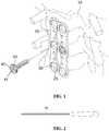
- FIG. 3is a schematic view showing a loosening driver that is used for a fixing apparatus for cervical vertebrae according to an embodiment of the present invention.
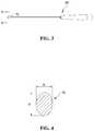
- FIG. 4is a cross-sectional view taken along line A-A′ of FIG. 3 .
- FIG. 1shows a state in which a fixing apparatus for cervical vertebrae according to an embodiment of the present invention is mounted in the cervical vertebrae
- FIG. 2is a schematic view showing an insertion driver that is used for a fixing apparatus for cervical vertebrae according to an embodiment of the present invention
- FIG. 3is a schematic view showing a loosening driver that is used for a fixing apparatus for cervical vertebrae according to an embodiment of the present invention
- FIG. 4is a cross-sectional view taken along line A-A′ of FIG. 3 .
- the fixing system for cervical vertebraeincludes a fixing apparatus for cervical vertebrae, an insertion driver 50 , and a loosening driver 60 .
- the fixing apparatus for cervical vertebraeis constituted of a cervical vertebrae-fixing plate 20 and a screw 40 that is inserted into cervical vertebrae 10 , and serves to fix the cervical vertebrae 10 .
- the screw 40has a screw head with a screw groove including a center groove 41 and at least one slot 42 having a length equal to the diameter of the screw head, wherein the at least one slot 42 transverses the center groove 41 such that both ends of the at least one slot 42 open in a radial direction of the screw head.
- a vertebral body in which a lesion is causedis removed, an artificial implant is inserted into a place in which the vertebral body is removed, and then the positional relationship between the inserted artificial implant and the neighboring vertebral body is fixed.
- the cervical vertebrae-fixing plate 20may be a plate-shaped metal plate, and a predetermined number of screw holes 25 are formed thereon. Through the screw holes 25 formed on the cervical vertebrae-fixing plate 20 , the screw 40 may be inserted into the cervical vertebrae 10 . In addition, clips 30 are provided in each of the screw holes 25 , so that the screw 40 may be prevented from being easily shaken or escaped backward while holding the screw 40 inserted into the cervical vertebrae 10 .
- two clips 30may be provided in positions facing each other on the circumference of the screw holes 25 , and in some cases, the number of the clips 30 to be provided and the position of the clips 30 to be provided on the circumference may vary.
- FIGS. 1 and 2a process in which the cervical vertebrae-fixing plate 20 is fixed to the cervical vertebrae 10 will be described in more detail with reference to FIGS. 1 and 2 .
- Six screw holes 25are formed on the cervical vertebrae-fixing plate 20 , and two clips 30 are provided in the positions facing each other on the circumference of each of the screw holes 25 and the provided clips may protrude from the inner circumference of each of the screw holes 25 .
- a vertebral body in which a lesion is causedis removed, an artificial implant is inserted into a place in which the vertebral body is removed, the cervical vertebrae-fixing plate 20 is put to the inserted artificial implant and portions of the cervical vertebrae 10 in which the upper and lower vertebral bodies adjacent to the inserted artificial implant are positioned, and then the screw 40 is inserted into the cervical vertebrae 10 by turning the screw 40 having passed through the screw hole 25 using the insertion driver 50 .
- the screw 40 inserted into the cervical vertebrae 10 in this manneris held by the clips 30 positioned in the screw hole 25 so that the separation of the screw 40 may be prevented.
- the insertion driver 50may enable the screw 40 to be inserted into the cervical vertebrae 10 by turning the screw 40 , and the shape of a front end portion of the insertion driver 50 may vary depending on the shape of a groove on the screw 40 to be used, but the front end portion of the insertion driver 50 may have a hexagonal or star-like shape.
- the loosening driver 60is a driver that loosens the screw 40 inserted into the cervical vertebrae 10 , and a convex portion 70 is formed at the rear of the front end portion of the loosening driver 60 which is fitted in the groove on the screw 40 .
- the convex portion 70may have a shape which ascends from a starting portion thereof towards a peak thereof and then descends from the peak towards a distal end portion thereof, and the cross-section of the convex portion 70 may have an oval shape.
- a distance between peaks out of the convex portion 70 , which are vertically farthest from the main body of the loosening driver 60 and symmetrical to each other, that is, a major axis (a) of the cross-section having the largest area among the cross-sections of the oval-shaped convex portion 70may be equal to a diameter of the screw hole 25 of the cervical vertebrae-fixing plate 20 or a diameter of the screw head of the screw 40 .
- a minor axis (b) of the cross-section having the largest area among the cross-sections of the oval-shaped convex portion 70may be equal to a distance between both clips 30 provided to face each other on the circumference of the screw hole 25 .
- the convex portion 70may be formed in the front end portion of the loosening driver 60 , and spread the clips 30 while the screw 40 is loosened due to the sizes of the above-described cross-sections of the convex portion 70 , and thereby the removal of the screw 40 may be facilitated.
- the front end portion of the loosening driver 60is fitted in the groove on the screw 40 held by the clips 30 , and then the convex portion 70 of the loosening driver 60 spreads the clips 30 while the screw 40 is loosened by turning the loosening driver 60 , and thereby the pressure applied to the screw 40 may be removed by the clips 30 , so that the loosening or removal of the screw 40 inserted into the cervical vertebrae 10 may be facilitated.
- the fixing system for cervical vertebrae according to an embodiment of the present inventionhas been described, and hereinafter, a fixing system for cervical vertebrae according to another embodiment of the present invention will be described.
- the difference between the fixing system for cervical vertebrae according to an embodiment of the present invention and the fixing system for cervical vertebrae according to another embodiment of the present inventionis that the convex portion is separately attached to the main body of the loosening driver as a replaceable portion as opposed to an integrated portion with respect to the main body of the loosening driver.
- the convex portion according to another embodiment of the present inventionmay have various shapes and sizes, and in particular, the thickness of the peak portion of the convex portion may be varied, and an attachment groove may be provided in an attachment position of the loosening driver to which the convex portion is attached.
- the sizes of the screw holes and clips of the cervical vertebrae-fixing platemay be varied, and therefore the convex portion may be selected to conform to the sizes of the screw holes and clips, the selected convex portion may be mounted in the attachment groove of the loosening driver in such a manner as to be forcibly fitted therein, and then the operation for cervical vertebrae may be performed.
- the loosening driver according to another embodiment of the present inventionmay be used for a variety of cervical vertebrae-fixing plates, and thereby the high compatibility may be realized and the convenience of the process of the operation for cervical vertebrae may be improved.
- the loosening driver used for the fixing system for cervical vertebraemay include the convex portion formed in the front end portion thereof, and thereby the convex portion may spread the clips positioned in the screw holes of the cervical vertebrae-fixing plate, so that the removal of the screw may be facilitated in the process of the operation for cervical vertebrae, resulting in realizing the smooth operation for cervical vertebrae.
- the fixing system for cervical vertebraein which an operation for cervical vertebrae may be smoothly performed by easily removing the screw inserted into the cervical vertebrae, and the driver used for The fixing apparatus for cervical vertebrae.
Landscapes
- Health & Medical Sciences (AREA)
- Orthopedic Medicine & Surgery (AREA)
- Surgery (AREA)
- Life Sciences & Earth Sciences (AREA)
- Neurology (AREA)
- Medical Informatics (AREA)
- Biomedical Technology (AREA)
- Heart & Thoracic Surgery (AREA)
- Engineering & Computer Science (AREA)
- Molecular Biology (AREA)
- Animal Behavior & Ethology (AREA)
- General Health & Medical Sciences (AREA)
- Public Health (AREA)
- Veterinary Medicine (AREA)
- Nuclear Medicine, Radiotherapy & Molecular Imaging (AREA)
- Surgical Instruments (AREA)
Abstract
Description
Claims (5)
Applications Claiming Priority (2)
| Application Number | Priority Date | Filing Date | Title |
|---|---|---|---|
| KR10-2014-0156191 | 2014-11-11 | ||
| KR1020140156191AKR101639887B1 (en) | 2014-11-11 | 2014-11-11 | A system for fixing cervical vertebrae and a driver used for an appratus for fixing cervical vertebrae |
Publications (2)
| Publication Number | Publication Date |
|---|---|
| US20160128738A1 US20160128738A1 (en) | 2016-05-12 |
| US10729473B2true US10729473B2 (en) | 2020-08-04 |
Family
ID=55911322
Family Applications (1)
| Application Number | Title | Priority Date | Filing Date |
|---|---|---|---|
| US14/938,286Active2036-07-30US10729473B2 (en) | 2014-11-11 | 2015-11-11 | System for fixing cervical vertebrae and a driver used for an apparatus for fixing cervical vertebrae |
Country Status (2)
| Country | Link |
|---|---|
| US (1) | US10729473B2 (en) |
| KR (1) | KR101639887B1 (en) |
Families Citing this family (1)
| Publication number | Priority date | Publication date | Assignee | Title |
|---|---|---|---|---|
| EP3329870B1 (en)* | 2015-07-27 | 2023-08-02 | CG Bio Co., Ltd. | Apparatus for fixing cervical spine |
Citations (105)
| Publication number | Priority date | Publication date | Assignee | Title |
|---|---|---|---|---|
| US4027932A (en) | 1974-05-25 | 1977-06-07 | Skf Industrial Trading And Development Company B.V. | Clutch release bearing |
| US4359318A (en) | 1981-12-18 | 1982-11-16 | Neal Gittleman | Dental implant |
| US4474516A (en) | 1981-05-25 | 1984-10-02 | Hilti Aktiengesellschaft | Anchor bolt assembly |
| US4678383A (en) | 1983-08-17 | 1987-07-07 | Hilti Aktiengesellschaft | Expansion anchor assembly |
| US5127407A (en) | 1989-08-17 | 1992-07-07 | Critikon, Inc. | Epidural oxygen sensor |
| US5265504A (en)* | 1992-12-01 | 1993-11-30 | Hermann Fruhm | Cartridge type screwdriver |
| KR19990035953A (en) | 1995-08-22 | 1999-05-25 | 레이봉 알랭 | Screw Press-fit Sheet Anchors |
| US6171311B1 (en) | 1996-10-18 | 2001-01-09 | Marc Richelsoph | Transverse connector |
| US6249946B1 (en)* | 2000-03-24 | 2001-06-26 | Small Steel Ring Company | Removal tool for internal and external retaining rings |
| US6258089B1 (en)* | 1998-05-19 | 2001-07-10 | Alphatec Manufacturing, Inc. | Anterior cervical plate and fixation system |
| US6290701B1 (en) | 2000-01-11 | 2001-09-18 | Albert Enayati | Bioabsorbable rivet bone fastener |
| US6331179B1 (en)* | 2000-01-06 | 2001-12-18 | Spinal Concepts, Inc. | System and method for stabilizing the human spine with a bone plate |
| US20020040241A1 (en) | 2000-06-14 | 2002-04-04 | Teppo Jarvinen | Fixation anchor |
| US6402757B1 (en) | 1999-03-12 | 2002-06-11 | Biomet, Inc. | Cannulated fastener system for repair of bone fracture |
| US6436100B1 (en) | 1998-08-07 | 2002-08-20 | J. Lee Berger | Cannulated internally threaded bone screw and reduction driver device |
| US20020151899A1 (en)* | 2001-04-17 | 2002-10-17 | Bailey Kirk J. | Anterior cervical plating system |
| KR20020082009A (en) | 2001-04-23 | 2002-10-30 | 김지형 | Block plate for anterior cervical fusion |
| US20030135274A1 (en) | 1996-11-27 | 2003-07-17 | Jo Hays | Graft ligament anchor and method for attaching a graft ligament to a bone |
| US20030187440A1 (en) | 2002-03-12 | 2003-10-02 | Marc Richelsoph | Bone plate and screw retaining mechanism |
| US6652525B1 (en) | 1998-04-30 | 2003-11-25 | Sofamor S.N.C. | Anterior implant for the spine |
| KR20040001287A (en) | 2002-06-27 | 2004-01-07 | (주)태연메디칼 | Cervical vertebra fixation method and that system |
| US6767350B1 (en) | 1998-07-25 | 2004-07-27 | Helke Lob | Fixing element for bone fragments |
| US6778861B1 (en) | 1999-06-23 | 2004-08-17 | Geot Gesellschaft Fur Elektro-Osteo-Therapie G.M.B.H. | Bone screw comprising a device for electrostimulation |
| US20040220571A1 (en) | 1998-04-30 | 2004-11-04 | Richard Assaker | Bone plate assembly |
| KR200367241Y1 (en) | 2004-08-27 | 2004-11-10 | 진동규 | Spinal fixation apparatus |
| US20040243207A1 (en) | 2003-05-30 | 2004-12-02 | Olson Donald R. | Medical implant systems |
| US20040267361A1 (en) | 2003-06-27 | 2004-12-30 | Donnelly Lisa M. | Flexible tibial sheath |
| KR20050023111A (en) | 2003-08-29 | 2005-03-09 | (주)태연메디칼 | Spine supporting instrument |
| US20050059972A1 (en) | 2003-09-16 | 2005-03-17 | Spineco, Inc., An Ohio Corporation | Bone anchor prosthesis and system |
| US20050192577A1 (en) | 2004-02-26 | 2005-09-01 | Pioneer Laboratories, Inc. | Bone plate system and methods |
| US20050216027A1 (en)* | 2004-03-24 | 2005-09-29 | Suh Sean S | Extraction screwdriver |
| US20050261689A1 (en) | 2004-05-20 | 2005-11-24 | A-Spine Holding Group Corp. Ashg | Bone fixation device |
| US7029472B1 (en) | 1999-06-01 | 2006-04-18 | Fortin Frederic | Distraction device for the bones of children |
| US20060106390A1 (en) | 2004-11-18 | 2006-05-18 | Jensen David G | Composite bone fasteners |
| US20060149258A1 (en) | 2004-12-14 | 2006-07-06 | Sousa Joaquim P G | Surgical tool and method for fixation of ligaments |
| US20060217721A1 (en) | 2005-03-11 | 2006-09-28 | Suh Sean S | Translational hinged door plate system |
| US20060235410A1 (en) | 2005-04-15 | 2006-10-19 | Ralph James D | Surgical expansion fasteners |
| US20060247639A1 (en) | 2005-04-29 | 2006-11-02 | Sdgi Holdings, Inc. | Apparatus for retaining a bone anchor in a bone plate and method for use thereof |
| US20060293670A1 (en) | 2005-06-03 | 2006-12-28 | Smisson Hugh F Iii | Surgical stabilization system |
| US7194314B1 (en) | 2003-08-15 | 2007-03-20 | Northwestern University | Cochlear implant including a modiolar return electrode |
| US7235100B2 (en) | 2000-09-15 | 2007-06-26 | Tyco Healthcare Group Lp | Knotless tissue anchor |
| US20070233071A1 (en) | 2006-03-01 | 2007-10-04 | Sdgi Holdings, Inc. | Bone anchors having two or more portions exhibiting different performance characteristics and method of forming the same |
| KR20070112200A (en) | 2005-02-18 | 2007-11-22 | 워쏘우 오르쏘페딕 인코포레이티드 | Implants in surgical approach to the spine and methods for positioning them |
| US7302298B2 (en) | 2002-11-27 | 2007-11-27 | Northstar Neuroscience, Inc | Methods and systems employing intracranial electrodes for neurostimulation and/or electroencephalography |
| US20080039846A1 (en) | 2006-08-10 | 2008-02-14 | Shih-Tseng Lee | Expansion screw set and hollow nail and interior nail thereof |
| KR20080059920A (en) | 2006-12-26 | 2008-07-01 | 주식회사 엔에이치에스 | Spinal Fixation Device |
| US20080161864A1 (en) | 2006-09-29 | 2008-07-03 | Depuy Mitek, Inc. | Femoral fixation |
| US20080188897A1 (en) | 2006-10-02 | 2008-08-07 | The Cleveland Clinic Foundation | Fastener assembly |
| US20080221624A1 (en) | 2005-10-17 | 2008-09-11 | Gooch Hubert L | Systems and Methods for the Medical Treatment of Structural Tissue |
| WO2008146981A1 (en) | 2007-05-31 | 2008-12-04 | Gs Medical Co., Ltd. | A spinal screw module |
| KR20090015933A (en) | 2006-04-24 | 2009-02-12 | 워쏘우 오르쏘페딕 인코포레이티드 | Connector device |
| US20090125072A1 (en) | 2007-11-13 | 2009-05-14 | Neubardt Seth L | Surgical bone screw construction |
| WO2009105106A2 (en) | 2008-02-21 | 2009-08-27 | Integrity Intellect, Inc. | Implant equipped for nerve location and method of use |
| KR20090111774A (en) | 2008-04-22 | 2009-10-27 | 비이더만 모테크 게엠베하 | Assembly tool for assembling bone fixation |
| US20090318970A1 (en) | 2008-06-19 | 2009-12-24 | Butler Michael S | Spinal Rod Connectors Configured to Retain Spinal Rods of Varying Diameters |
| US20100036467A1 (en) | 2006-05-01 | 2010-02-11 | Neue Magnetodyn Gmbh | Stimulation device for osteosynthesis and endoprosthetics |
| US7662154B2 (en) | 2005-09-16 | 2010-02-16 | Blackstone Medical, Inc. | Anterior cervical plating system |
| US20100049256A1 (en) | 2007-01-30 | 2010-02-25 | Dong Myung Jeon | Anterior cerivcal plating system |
| US20100106198A1 (en) | 2008-10-23 | 2010-04-29 | Warsaw Orthopedic, Inc | Nerve stimulating bone screw |
| US20100121383A1 (en) | 2008-11-10 | 2010-05-13 | Todd Stanaford | Method, system, and apparatus for mammalian bony segment stabilization |
| KR20100124709A (en) | 2007-12-21 | 2010-11-29 | 앵쁠라네 | Device for anchoring a tissue in a bone |
| US20110022097A1 (en) | 2009-07-24 | 2011-01-27 | Spinal USA LLC | Bone plate screw-blocking systems and methods |
| US20110029023A1 (en) | 2009-07-30 | 2011-02-03 | Clariance | Slide-type anti-backout device for prosthesis |
| US20110106159A1 (en) | 2008-06-05 | 2011-05-05 | Seaspine, Inc. | Spinal fixation plate assembly |
| US20110144702A1 (en) | 2004-04-20 | 2011-06-16 | Spineco, Inc. | Implant device |
| US20110152934A1 (en) | 2009-12-23 | 2011-06-23 | Asaad Wagdy W | Transconnector for coupling first and second spinal fixation elements |
| JP2011139901A (en) | 2010-01-08 | 2011-07-21 | Biedermann Motech Gmbh & Co Kg | Bone screw |
| US20110230885A1 (en) | 2010-03-19 | 2011-09-22 | Nextremity Solutions, Llc | Dynamic bone plate |
| US20110264151A1 (en) | 2010-04-26 | 2011-10-27 | Timothy Davis | Bone fixation device and method of validating its proper placement |
| KR20120039622A (en) | 2009-06-17 | 2012-04-25 | 신세스 게엠바하 | Revision connector for spinal constructs |
| KR20120040309A (en) | 2010-10-19 | 2012-04-27 | 인하대학교 산학협력단 | Ballon anchor reinforcing pedicle screw in osteoporotic spine |
| KR20120052265A (en) | 2009-07-06 | 2012-05-23 | 신세스 게엠바하 | Expandable fixation assemblies |
| KR20120057758A (en) | 2010-11-27 | 2012-06-07 | 서울대학교산학협력단 | Implant for neurotization by lectrostimulation |
| US20120185001A1 (en) | 2011-01-14 | 2012-07-19 | Warsaw Orthopedic, Inc. | Bone Anchors Compatible for Use with Neural Integrity Monitoring Systems and Procedures |
| US20120232595A1 (en) | 2011-03-07 | 2012-09-13 | Tyler HOLSCHLAG | Fastener retention system for spinal plates |
| US20120265258A1 (en) | 2011-04-14 | 2012-10-18 | Brian Garvey | Expanding Spinal Anchor |
| US20120271363A1 (en) | 2009-11-05 | 2012-10-25 | The Johns Hopkins University | Universally deployable and expandable bone screw anchor |
| US20120289978A1 (en) | 2011-05-13 | 2012-11-15 | Warsaw Orthopedic, Inc. | Retaining mechansim |
| KR20130004669A (en) | 2011-07-04 | 2013-01-14 | 주식회사 솔고 바이오메디칼 | Instrument for fixing of cervical vertebrae |
| US20130023936A1 (en) | 2011-07-19 | 2013-01-24 | Moti Altarac | Anterior cervical plate |
| KR20130015081A (en) | 2011-08-02 | 2013-02-13 | 전남대학교산학협력단 | Medical screw assembly having screw line structure of rake type |
| US20130041413A1 (en) | 2010-11-28 | 2013-02-14 | Shandong Hangwei Orthopedics Medical Instrument Co., Ltd. | Universal locking and compression device for bone plate |
| US8454667B2 (en) | 2010-12-16 | 2013-06-04 | Warsaw Orhtopedic, Inc. | Retaining mechanism |
| US20130231704A1 (en) | 2010-11-10 | 2013-09-05 | Zimmer Spine | Bone anchor |
| US20130304067A1 (en) | 2012-05-10 | 2013-11-14 | Spinal Simplicity Llc | Dynamic bone fracture plates |
| KR101331429B1 (en) | 2012-08-03 | 2013-11-21 | 주식회사 솔고 바이오메디칼 | Snap type fixing apparatus for cervical spine |
| US20130325074A1 (en) | 2012-06-05 | 2013-12-05 | Blackstone Medical, Inc. | Orthopedic devices with a locking mechanism |
| KR20140003938A (en) | 2012-07-02 | 2014-01-10 | 한생수 | Anchor bolt |
| US8628325B2 (en) | 2006-09-03 | 2014-01-14 | Dentack Impants Ltd. | Expandable dental implants of high surface area and methods of expanding the same |
| KR20140018796A (en) | 2012-08-03 | 2014-02-13 | 주식회사 솔고 바이오메디칼 | Apparatus for fixing a cervical spine having self tension part |
| US20140066997A1 (en) | 2012-08-31 | 2014-03-06 | Warsaw Orthopedic, Inc. | Retaining mechanism |
| KR20140052320A (en) | 2012-10-24 | 2014-05-07 | 주식회사 지에스메디칼 | Cervical plate |
| KR101413732B1 (en) | 2007-02-23 | 2014-07-01 | 비이더만 테크놀로지스 게엠베하 & 코. 카게 | Stabilization device for stabilization of vertebrae and rod connector used in the device |
| US8906077B2 (en) | 2007-11-09 | 2014-12-09 | Stryker Spine | Cervical plate with a feedback device for selective association with bone screw blocking mechanism |
| US8940030B1 (en) | 2011-01-28 | 2015-01-27 | Nuvasive, Inc. | Spinal fixation system and related methods |
| US8956394B1 (en) | 2014-08-05 | 2015-02-17 | Woven Orthopedic Technologies, Llc | Woven retention devices, systems and methods |
| US20150134013A1 (en) | 2013-11-13 | 2015-05-14 | Kamaljit S. Paul | Bone treatment implants, and springs therefore |
| US20150201982A1 (en) | 2014-01-20 | 2015-07-23 | Neurostructures, Inc. | Anterior cervical plate |
| US20150216573A1 (en) | 2013-01-16 | 2015-08-06 | Spinefrontier, Inc | Bone fastener for a spinal fixation assembly |
| US20150230838A1 (en) | 2012-08-28 | 2015-08-20 | Koc Universitesi | Bone plate |
| KR20150120105A (en) | 2014-04-17 | 2015-10-27 | 경북대학교 산학협력단 | Screw fixing apparatus |
| US20160206351A1 (en) | 2014-08-11 | 2016-07-21 | Corentec Co., Ltd. | Spine fixing apparatus |
| US20160278834A1 (en) | 2015-03-24 | 2016-09-29 | Biotronik Ag | Resorbable metal screw with increased torsional strength for osteopathy |
| US9775652B2 (en) | 2014-02-20 | 2017-10-03 | Mastros Innovations, Llc | Lateral plate |
| US9943341B2 (en)* | 2013-07-16 | 2018-04-17 | K2M, Llc | Retention plate member for a spinal plate system |
- 2014
- 2014-11-11KRKR1020140156191Apatent/KR101639887B1/enactiveActive
- 2015
- 2015-11-11USUS14/938,286patent/US10729473B2/enactiveActive
Patent Citations (122)
| Publication number | Priority date | Publication date | Assignee | Title |
|---|---|---|---|---|
| US4027932A (en) | 1974-05-25 | 1977-06-07 | Skf Industrial Trading And Development Company B.V. | Clutch release bearing |
| US4474516A (en) | 1981-05-25 | 1984-10-02 | Hilti Aktiengesellschaft | Anchor bolt assembly |
| US4359318A (en) | 1981-12-18 | 1982-11-16 | Neal Gittleman | Dental implant |
| US4678383A (en) | 1983-08-17 | 1987-07-07 | Hilti Aktiengesellschaft | Expansion anchor assembly |
| US5127407A (en) | 1989-08-17 | 1992-07-07 | Critikon, Inc. | Epidural oxygen sensor |
| US5265504A (en)* | 1992-12-01 | 1993-11-30 | Hermann Fruhm | Cartridge type screwdriver |
| KR19990035953A (en) | 1995-08-22 | 1999-05-25 | 레이봉 알랭 | Screw Press-fit Sheet Anchors |
| US6171311B1 (en) | 1996-10-18 | 2001-01-09 | Marc Richelsoph | Transverse connector |
| US20030135274A1 (en) | 1996-11-27 | 2003-07-17 | Jo Hays | Graft ligament anchor and method for attaching a graft ligament to a bone |
| US6652525B1 (en) | 1998-04-30 | 2003-11-25 | Sofamor S.N.C. | Anterior implant for the spine |
| US20040220571A1 (en) | 1998-04-30 | 2004-11-04 | Richard Assaker | Bone plate assembly |
| US6258089B1 (en)* | 1998-05-19 | 2001-07-10 | Alphatec Manufacturing, Inc. | Anterior cervical plate and fixation system |
| US6767350B1 (en) | 1998-07-25 | 2004-07-27 | Helke Lob | Fixing element for bone fragments |
| US6436100B1 (en) | 1998-08-07 | 2002-08-20 | J. Lee Berger | Cannulated internally threaded bone screw and reduction driver device |
| US6402757B1 (en) | 1999-03-12 | 2002-06-11 | Biomet, Inc. | Cannulated fastener system for repair of bone fracture |
| US7029472B1 (en) | 1999-06-01 | 2006-04-18 | Fortin Frederic | Distraction device for the bones of children |
| US6778861B1 (en) | 1999-06-23 | 2004-08-17 | Geot Gesellschaft Fur Elektro-Osteo-Therapie G.M.B.H. | Bone screw comprising a device for electrostimulation |
| US6331179B1 (en)* | 2000-01-06 | 2001-12-18 | Spinal Concepts, Inc. | System and method for stabilizing the human spine with a bone plate |
| US6290701B1 (en) | 2000-01-11 | 2001-09-18 | Albert Enayati | Bioabsorbable rivet bone fastener |
| US6249946B1 (en)* | 2000-03-24 | 2001-06-26 | Small Steel Ring Company | Removal tool for internal and external retaining rings |
| US20020040241A1 (en) | 2000-06-14 | 2002-04-04 | Teppo Jarvinen | Fixation anchor |
| US7235100B2 (en) | 2000-09-15 | 2007-06-26 | Tyco Healthcare Group Lp | Knotless tissue anchor |
| US20020151899A1 (en)* | 2001-04-17 | 2002-10-17 | Bailey Kirk J. | Anterior cervical plating system |
| KR20020082009A (en) | 2001-04-23 | 2002-10-30 | 김지형 | Block plate for anterior cervical fusion |
| US20030187440A1 (en) | 2002-03-12 | 2003-10-02 | Marc Richelsoph | Bone plate and screw retaining mechanism |
| KR20040001287A (en) | 2002-06-27 | 2004-01-07 | (주)태연메디칼 | Cervical vertebra fixation method and that system |
| US7302298B2 (en) | 2002-11-27 | 2007-11-27 | Northstar Neuroscience, Inc | Methods and systems employing intracranial electrodes for neurostimulation and/or electroencephalography |
| US20040243207A1 (en) | 2003-05-30 | 2004-12-02 | Olson Donald R. | Medical implant systems |
| US20040267361A1 (en) | 2003-06-27 | 2004-12-30 | Donnelly Lisa M. | Flexible tibial sheath |
| US7194314B1 (en) | 2003-08-15 | 2007-03-20 | Northwestern University | Cochlear implant including a modiolar return electrode |
| KR20050023111A (en) | 2003-08-29 | 2005-03-09 | (주)태연메디칼 | Spine supporting instrument |
| US20050059972A1 (en) | 2003-09-16 | 2005-03-17 | Spineco, Inc., An Ohio Corporation | Bone anchor prosthesis and system |
| US20060161157A1 (en)* | 2004-02-26 | 2006-07-20 | Lawrence Mosca | Bone plate system and methods |
| US20050192577A1 (en) | 2004-02-26 | 2005-09-01 | Pioneer Laboratories, Inc. | Bone plate system and methods |
| KR20070026472A (en) | 2004-03-24 | 2007-03-08 | 신테스 (유.에스.에이.) | Extraction screw driver |
| US20050216027A1 (en)* | 2004-03-24 | 2005-09-29 | Suh Sean S | Extraction screwdriver |
| US20110144702A1 (en) | 2004-04-20 | 2011-06-16 | Spineco, Inc. | Implant device |
| US20050261689A1 (en) | 2004-05-20 | 2005-11-24 | A-Spine Holding Group Corp. Ashg | Bone fixation device |
| KR200367241Y1 (en) | 2004-08-27 | 2004-11-10 | 진동규 | Spinal fixation apparatus |
| US20060106390A1 (en) | 2004-11-18 | 2006-05-18 | Jensen David G | Composite bone fasteners |
| US20060149258A1 (en) | 2004-12-14 | 2006-07-06 | Sousa Joaquim P G | Surgical tool and method for fixation of ligaments |
| KR20070112200A (en) | 2005-02-18 | 2007-11-22 | 워쏘우 오르쏘페딕 인코포레이티드 | Implants in surgical approach to the spine and methods for positioning them |
| US20060217721A1 (en) | 2005-03-11 | 2006-09-28 | Suh Sean S | Translational hinged door plate system |
| US20060235410A1 (en) | 2005-04-15 | 2006-10-19 | Ralph James D | Surgical expansion fasteners |
| US20060247639A1 (en) | 2005-04-29 | 2006-11-02 | Sdgi Holdings, Inc. | Apparatus for retaining a bone anchor in a bone plate and method for use thereof |
| US8057521B2 (en) | 2005-06-03 | 2011-11-15 | Southern Spine, Llc | Surgical stabilization system |
| US20060293670A1 (en) | 2005-06-03 | 2006-12-28 | Smisson Hugh F Iii | Surgical stabilization system |
| US7662154B2 (en) | 2005-09-16 | 2010-02-16 | Blackstone Medical, Inc. | Anterior cervical plating system |
| US20080221624A1 (en) | 2005-10-17 | 2008-09-11 | Gooch Hubert L | Systems and Methods for the Medical Treatment of Structural Tissue |
| US20070233071A1 (en) | 2006-03-01 | 2007-10-04 | Sdgi Holdings, Inc. | Bone anchors having two or more portions exhibiting different performance characteristics and method of forming the same |
| KR20090015933A (en) | 2006-04-24 | 2009-02-12 | 워쏘우 오르쏘페딕 인코포레이티드 | Connector device |
| US20100036467A1 (en) | 2006-05-01 | 2010-02-11 | Neue Magnetodyn Gmbh | Stimulation device for osteosynthesis and endoprosthetics |
| US20080039846A1 (en) | 2006-08-10 | 2008-02-14 | Shih-Tseng Lee | Expansion screw set and hollow nail and interior nail thereof |
| US8628325B2 (en) | 2006-09-03 | 2014-01-14 | Dentack Impants Ltd. | Expandable dental implants of high surface area and methods of expanding the same |
| US20080161864A1 (en) | 2006-09-29 | 2008-07-03 | Depuy Mitek, Inc. | Femoral fixation |
| US20080188897A1 (en) | 2006-10-02 | 2008-08-07 | The Cleveland Clinic Foundation | Fastener assembly |
| KR100850322B1 (en) | 2006-12-26 | 2008-08-12 | 주식회사 엔에이치에스 | Apparatus for percutaneous pedicle screw fixation |
| KR20080059920A (en) | 2006-12-26 | 2008-07-01 | 주식회사 엔에이치에스 | Spinal Fixation Device |
| US20100049256A1 (en) | 2007-01-30 | 2010-02-25 | Dong Myung Jeon | Anterior cerivcal plating system |
| KR101413732B1 (en) | 2007-02-23 | 2014-07-01 | 비이더만 테크놀로지스 게엠베하 & 코. 카게 | Stabilization device for stabilization of vertebrae and rod connector used in the device |
| KR100872529B1 (en) | 2007-05-31 | 2008-12-08 | 주식회사 지에스메디칼 | Pedicle screw module |
| KR20080105506A (en) | 2007-05-31 | 2008-12-04 | 주식회사 지에스메디칼 | Pedicle screw module |
| WO2008146981A1 (en) | 2007-05-31 | 2008-12-04 | Gs Medical Co., Ltd. | A spinal screw module |
| US9918760B2 (en) | 2007-11-09 | 2018-03-20 | Stryker European Holdings I, Llc | Cervical plate with a feedback device for selective association with bone screw blocking mechanism |
| US8906077B2 (en) | 2007-11-09 | 2014-12-09 | Stryker Spine | Cervical plate with a feedback device for selective association with bone screw blocking mechanism |
| US20090125072A1 (en) | 2007-11-13 | 2009-05-14 | Neubardt Seth L | Surgical bone screw construction |
| KR20100124709A (en) | 2007-12-21 | 2010-11-29 | 앵쁠라네 | Device for anchoring a tissue in a bone |
| WO2009105106A2 (en) | 2008-02-21 | 2009-08-27 | Integrity Intellect, Inc. | Implant equipped for nerve location and method of use |
| KR20090111774A (en) | 2008-04-22 | 2009-10-27 | 비이더만 모테크 게엠베하 | Assembly tool for assembling bone fixation |
| US20110106159A1 (en) | 2008-06-05 | 2011-05-05 | Seaspine, Inc. | Spinal fixation plate assembly |
| US20090318970A1 (en) | 2008-06-19 | 2009-12-24 | Butler Michael S | Spinal Rod Connectors Configured to Retain Spinal Rods of Varying Diameters |
| US20100106198A1 (en) | 2008-10-23 | 2010-04-29 | Warsaw Orthopedic, Inc | Nerve stimulating bone screw |
| US20100121383A1 (en) | 2008-11-10 | 2010-05-13 | Todd Stanaford | Method, system, and apparatus for mammalian bony segment stabilization |
| KR20120039622A (en) | 2009-06-17 | 2012-04-25 | 신세스 게엠바하 | Revision connector for spinal constructs |
| KR20120052265A (en) | 2009-07-06 | 2012-05-23 | 신세스 게엠바하 | Expandable fixation assemblies |
| US8419777B2 (en) | 2009-07-24 | 2013-04-16 | Spinal Usa, Inc. | Bone plate screw-blocking systems and methods |
| US20110022097A1 (en) | 2009-07-24 | 2011-01-27 | Spinal USA LLC | Bone plate screw-blocking systems and methods |
| US20110029023A1 (en) | 2009-07-30 | 2011-02-03 | Clariance | Slide-type anti-backout device for prosthesis |
| US20120271363A1 (en) | 2009-11-05 | 2012-10-25 | The Johns Hopkins University | Universally deployable and expandable bone screw anchor |
| US20110152934A1 (en) | 2009-12-23 | 2011-06-23 | Asaad Wagdy W | Transconnector for coupling first and second spinal fixation elements |
| JP2011139901A (en) | 2010-01-08 | 2011-07-21 | Biedermann Motech Gmbh & Co Kg | Bone screw |
| US20110230885A1 (en) | 2010-03-19 | 2011-09-22 | Nextremity Solutions, Llc | Dynamic bone plate |
| US8758347B2 (en) | 2010-03-19 | 2014-06-24 | Nextremity Solutions, Inc. | Dynamic bone plate |
| KR20130016303A (en) | 2010-03-19 | 2013-02-14 | 넥스트레미티 솔루션스 엘엘씨 | Dynamic corrugated plate |
| US20110264151A1 (en) | 2010-04-26 | 2011-10-27 | Timothy Davis | Bone fixation device and method of validating its proper placement |
| KR101142895B1 (en) | 2010-10-19 | 2012-05-10 | 인하대학교 산학협력단 | Ballon anchor reinforcing pedicle screw in osteoporotic spine |
| KR20120040309A (en) | 2010-10-19 | 2012-04-27 | 인하대학교 산학협력단 | Ballon anchor reinforcing pedicle screw in osteoporotic spine |
| US20130231704A1 (en) | 2010-11-10 | 2013-09-05 | Zimmer Spine | Bone anchor |
| KR20120057758A (en) | 2010-11-27 | 2012-06-07 | 서울대학교산학협력단 | Implant for neurotization by lectrostimulation |
| US20130041413A1 (en) | 2010-11-28 | 2013-02-14 | Shandong Hangwei Orthopedics Medical Instrument Co., Ltd. | Universal locking and compression device for bone plate |
| US8454667B2 (en) | 2010-12-16 | 2013-06-04 | Warsaw Orhtopedic, Inc. | Retaining mechanism |
| US20120185001A1 (en) | 2011-01-14 | 2012-07-19 | Warsaw Orthopedic, Inc. | Bone Anchors Compatible for Use with Neural Integrity Monitoring Systems and Procedures |
| US8940030B1 (en) | 2011-01-28 | 2015-01-27 | Nuvasive, Inc. | Spinal fixation system and related methods |
| US20120232595A1 (en) | 2011-03-07 | 2012-09-13 | Tyler HOLSCHLAG | Fastener retention system for spinal plates |
| JP2014517739A (en) | 2011-04-14 | 2014-07-24 | グローバス メディカル インコーポレイティッド | Expandable spinal anchor |
| US20120265258A1 (en) | 2011-04-14 | 2012-10-18 | Brian Garvey | Expanding Spinal Anchor |
| US20120289978A1 (en) | 2011-05-13 | 2012-11-15 | Warsaw Orthopedic, Inc. | Retaining mechansim |
| KR20130004669A (en) | 2011-07-04 | 2013-01-14 | 주식회사 솔고 바이오메디칼 | Instrument for fixing of cervical vertebrae |
| US9918749B2 (en) | 2011-07-19 | 2018-03-20 | Howmedica Osteonics Corp. | Anterior cervical plate |
| US20130023936A1 (en) | 2011-07-19 | 2013-01-24 | Moti Altarac | Anterior cervical plate |
| KR20130015081A (en) | 2011-08-02 | 2013-02-13 | 전남대학교산학협력단 | Medical screw assembly having screw line structure of rake type |
| US20130304067A1 (en) | 2012-05-10 | 2013-11-14 | Spinal Simplicity Llc | Dynamic bone fracture plates |
| US20130325074A1 (en) | 2012-06-05 | 2013-12-05 | Blackstone Medical, Inc. | Orthopedic devices with a locking mechanism |
| US20160166295A1 (en) | 2012-06-05 | 2016-06-16 | Blackstone Medical, Inc. | Orthopedic devices with a locking mechanism |
| US9265531B2 (en) | 2012-06-05 | 2016-02-23 | Blackstone Medical, Inc. | Orthopedic devices with a locking mechanism |
| KR20140003938A (en) | 2012-07-02 | 2014-01-10 | 한생수 | Anchor bolt |
| KR20140018796A (en) | 2012-08-03 | 2014-02-13 | 주식회사 솔고 바이오메디칼 | Apparatus for fixing a cervical spine having self tension part |
| KR101331429B1 (en) | 2012-08-03 | 2013-11-21 | 주식회사 솔고 바이오메디칼 | Snap type fixing apparatus for cervical spine |
| US20150230838A1 (en) | 2012-08-28 | 2015-08-20 | Koc Universitesi | Bone plate |
| US20140066997A1 (en) | 2012-08-31 | 2014-03-06 | Warsaw Orthopedic, Inc. | Retaining mechanism |
| US8932335B2 (en) | 2012-08-31 | 2015-01-13 | Warsaw Orthopedic, Inc. | Retaining mechanism |
| KR20140052320A (en) | 2012-10-24 | 2014-05-07 | 주식회사 지에스메디칼 | Cervical plate |
| US20150216573A1 (en) | 2013-01-16 | 2015-08-06 | Spinefrontier, Inc | Bone fastener for a spinal fixation assembly |
| US9943341B2 (en)* | 2013-07-16 | 2018-04-17 | K2M, Llc | Retention plate member for a spinal plate system |
| US20150134013A1 (en) | 2013-11-13 | 2015-05-14 | Kamaljit S. Paul | Bone treatment implants, and springs therefore |
| US20150201982A1 (en) | 2014-01-20 | 2015-07-23 | Neurostructures, Inc. | Anterior cervical plate |
| US9629664B2 (en) | 2014-01-20 | 2017-04-25 | Neurostructures, Inc. | Anterior cervical plate |
| US9775652B2 (en) | 2014-02-20 | 2017-10-03 | Mastros Innovations, Llc | Lateral plate |
| KR20150120105A (en) | 2014-04-17 | 2015-10-27 | 경북대학교 산학협력단 | Screw fixing apparatus |
| US8956394B1 (en) | 2014-08-05 | 2015-02-17 | Woven Orthopedic Technologies, Llc | Woven retention devices, systems and methods |
| US20160206351A1 (en) | 2014-08-11 | 2016-07-21 | Corentec Co., Ltd. | Spine fixing apparatus |
| US20160278834A1 (en) | 2015-03-24 | 2016-09-29 | Biotronik Ag | Resorbable metal screw with increased torsional strength for osteopathy |
Also Published As
| Publication number | Publication date |
|---|---|
| KR20160056150A (en) | 2016-05-19 |
| US20160128738A1 (en) | 2016-05-12 |
| KR101639887B1 (en) | 2016-07-14 |
Similar Documents
| Publication | Publication Date | Title |
|---|---|---|
| JP4545753B2 (en) | Spinal implant | |
| JP4988735B2 (en) | Rod extension for elongating fusion structures | |
| WO2008146981A1 (en) | A spinal screw module | |
| KR100896043B1 (en) | Rod clamp | |
| US9131972B2 (en) | Screw for fixing vertebra | |
| US9457180B2 (en) | Electrode clamp | |
| JP2006524114A (en) | Bone fixation plate device and method of using the same | |
| JP2007503928A (en) | Spinal deformity correction method using an anterior rod / plate system | |
| JP2005040600A (en) | Cervical vertebra fixing device and driver used for this | |
| AU2006232555A1 (en) | Non-circular stabilization sphere and method | |
| US10231764B2 (en) | System for fixing cervical vertebrae, an apparatus for fixing cervical vertebrae and a driver used for an apparatus for fixing cervical vertebrae | |
| US10729473B2 (en) | System for fixing cervical vertebrae and a driver used for an apparatus for fixing cervical vertebrae | |
| JP2012217826A (en) | Spinous process spacer | |
| JP6515191B2 (en) | Implant | |
| US10182918B2 (en) | Interspinous dynamic implant | |
| US20170150999A1 (en) | Method, system, and apparatus for breaking bony segment implant extension | |
| KR100491291B1 (en) | Cervical vertebra fixation system and that system | |
| KR20190125844A (en) | lumbar plate | |
| KR102260687B1 (en) | Spine fixing device for preventing screw break away | |
| US20170311991A1 (en) | Interspinous integration type implant | |
| JP2008537890A (en) | Spinal osteosynthesis device comprising a cage, an anterior plate and two longitudinal rods | |
| JP4188858B2 (en) | Bone flap holding plate | |
| CN112274235B (en) | Screw plug, fixing device and fixing device removal method | |
| CN104997577B (en) | A kind of non-resilient and elastomeric composition formula interspinous support device | |
| JPH0563513U (en) | Stripper |
Legal Events
| Date | Code | Title | Description |
|---|---|---|---|
| AS | Assignment | Owner name:KYUNGPOOK NATIONAL UNIVERSITY INDUSTRY-ACADEMIC COOPERATION FOUNDATION, KOREA, REPUBLIC OF Free format text:ASSIGNMENT OF ASSIGNORS INTEREST;ASSIGNOR:KIM, KYOUNG TAE;REEL/FRAME:037014/0450 Effective date:20151111 Owner name:KYUNGPOOK NATIONAL UNIVERSITY INDUSTRY-ACADEMIC CO Free format text:ASSIGNMENT OF ASSIGNORS INTEREST;ASSIGNOR:KIM, KYOUNG TAE;REEL/FRAME:037014/0450 Effective date:20151111 | |
| STPP | Information on status: patent application and granting procedure in general | Free format text:RESPONSE TO NON-FINAL OFFICE ACTION ENTERED AND FORWARDED TO EXAMINER | |
| STPP | Information on status: patent application and granting procedure in general | Free format text:FINAL REJECTION MAILED | |
| STPP | Information on status: patent application and granting procedure in general | Free format text:RESPONSE AFTER FINAL ACTION FORWARDED TO EXAMINER | |
| STPP | Information on status: patent application and granting procedure in general | Free format text:DOCKETED NEW CASE - READY FOR EXAMINATION | |
| STPP | Information on status: patent application and granting procedure in general | Free format text:NON FINAL ACTION MAILED | |
| STPP | Information on status: patent application and granting procedure in general | Free format text:RESPONSE TO NON-FINAL OFFICE ACTION ENTERED AND FORWARDED TO EXAMINER | |
| STPP | Information on status: patent application and granting procedure in general | Free format text:NOTICE OF ALLOWANCE MAILED -- APPLICATION RECEIVED IN OFFICE OF PUBLICATIONS | |
| STPP | Information on status: patent application and granting procedure in general | Free format text:PUBLICATIONS -- ISSUE FEE PAYMENT VERIFIED | |
| STCF | Information on status: patent grant | Free format text:PATENTED CASE | |
| MAFP | Maintenance fee payment | Free format text:PAYMENT OF MAINTENANCE FEE, 4TH YR, SMALL ENTITY (ORIGINAL EVENT CODE: M2551); ENTITY STATUS OF PATENT OWNER: SMALL ENTITY Year of fee payment:4 |