US10729039B2 - Liquid cooled rack information handling system having storage drive carrier for leak containment and vibration mitigation - Google Patents
Liquid cooled rack information handling system having storage drive carrier for leak containment and vibration mitigationDownload PDFInfo
- Publication number
- US10729039B2 US10729039B2US16/240,065US201916240065AUS10729039B2US 10729039 B2US10729039 B2US 10729039B2US 201916240065 AUS201916240065 AUS 201916240065AUS 10729039 B2US10729039 B2US 10729039B2
- Authority
- US
- United States
- Prior art keywords
- node
- liquid
- level
- leak
- rack
- Prior art date
- Legal status (The legal status is an assumption and is not a legal conclusion. Google has not performed a legal analysis and makes no representation as to the accuracy of the status listed.)
- Active
Links
Images


Classifications
- H—ELECTRICITY
- H05—ELECTRIC TECHNIQUES NOT OTHERWISE PROVIDED FOR
- H05K—PRINTED CIRCUITS; CASINGS OR CONSTRUCTIONAL DETAILS OF ELECTRIC APPARATUS; MANUFACTURE OF ASSEMBLAGES OF ELECTRICAL COMPONENTS
- H05K7/00—Constructional details common to different types of electric apparatus
- H05K7/20—Modifications to facilitate cooling, ventilating, or heating
- H05K7/20709—Modifications to facilitate cooling, ventilating, or heating for server racks or cabinets; for data centers, e.g. 19-inch computer racks
- H05K7/20836—Thermal management, e.g. server temperature control
- G—PHYSICS
- G06—COMPUTING OR CALCULATING; COUNTING
- G06F—ELECTRIC DIGITAL DATA PROCESSING
- G06F1/00—Details not covered by groups G06F3/00 - G06F13/00 and G06F21/00
- G06F1/16—Constructional details or arrangements
- G06F1/20—Cooling means
- G—PHYSICS
- G06—COMPUTING OR CALCULATING; COUNTING
- G06F—ELECTRIC DIGITAL DATA PROCESSING
- G06F1/00—Details not covered by groups G06F3/00 - G06F13/00 and G06F21/00
- G06F1/16—Constructional details or arrangements
- G06F1/20—Cooling means
- G06F1/206—Cooling means comprising thermal management
- H—ELECTRICITY
- H05—ELECTRIC TECHNIQUES NOT OTHERWISE PROVIDED FOR
- H05K—PRINTED CIRCUITS; CASINGS OR CONSTRUCTIONAL DETAILS OF ELECTRIC APPARATUS; MANUFACTURE OF ASSEMBLAGES OF ELECTRICAL COMPONENTS
- H05K7/00—Constructional details common to different types of electric apparatus
- H05K7/20—Modifications to facilitate cooling, ventilating, or heating
- H05K7/20709—Modifications to facilitate cooling, ventilating, or heating for server racks or cabinets; for data centers, e.g. 19-inch computer racks
- H05K7/20763—Liquid cooling without phase change
- H05K7/20772—Liquid cooling without phase change within server blades for removing heat from heat source
- H—ELECTRICITY
- H05—ELECTRIC TECHNIQUES NOT OTHERWISE PROVIDED FOR
- H05K—PRINTED CIRCUITS; CASINGS OR CONSTRUCTIONAL DETAILS OF ELECTRIC APPARATUS; MANUFACTURE OF ASSEMBLAGES OF ELECTRICAL COMPONENTS
- H05K7/00—Constructional details common to different types of electric apparatus
- H05K7/20—Modifications to facilitate cooling, ventilating, or heating
- H05K7/20709—Modifications to facilitate cooling, ventilating, or heating for server racks or cabinets; for data centers, e.g. 19-inch computer racks
- H05K7/20763—Liquid cooling without phase change
- H05K7/20781—Liquid cooling without phase change within cabinets for removing heat from server blades
- H—ELECTRICITY
- H05—ELECTRIC TECHNIQUES NOT OTHERWISE PROVIDED FOR
- H05K—PRINTED CIRCUITS; CASINGS OR CONSTRUCTIONAL DETAILS OF ELECTRIC APPARATUS; MANUFACTURE OF ASSEMBLAGES OF ELECTRICAL COMPONENTS
- H05K7/00—Constructional details common to different types of electric apparatus
- H05K7/20—Modifications to facilitate cooling, ventilating, or heating
- H05K7/20709—Modifications to facilitate cooling, ventilating, or heating for server racks or cabinets; for data centers, e.g. 19-inch computer racks
- H05K7/20763—Liquid cooling without phase change
- H05K7/2079—Liquid cooling without phase change within rooms for removing heat from cabinets
- G—PHYSICS
- G06—COMPUTING OR CALCULATING; COUNTING
- G06F—ELECTRIC DIGITAL DATA PROCESSING
- G06F2200/00—Indexing scheme relating to G06F1/04 - G06F1/32
- G06F2200/20—Indexing scheme relating to G06F1/20
- G06F2200/201—Cooling arrangements using cooling fluid
Definitions
- the present disclosuregenerally relates to information handling systems (IHS), and more particular to a direct-interface liquid cooled (DL) rack-configured HIS (RIHS), having a liquid cooling subsystem and liquid-cooled nodes. Still more particularly, the disclosure is related to mitigating risk to computing components from cooling liquid leaks within the RIHS.
- IHSinformation handling systems
- RIHSdirect-interface liquid cooled rack-configured HIS
- IHSsInformation Handling Systems
- An IHSgenerally processes, compiles, stores, and/or communicates information or data for business, personal, or other purposes, thereby allowing users to take advantage of the value of the information.
- IHSsmay also vary regarding what information is handled, how the information is handled, how much information is processed, stored, or communicated, and how quickly and efficiently the information may be processed, stored, or communicated.
- the variations in IHSsallow for IHSs to be general or configured for a specific user or specific use such as financial transaction processing, airline reservations, enterprise data storage, or global communications.
- IHSsmay include a variety of hardware and software components that may be configured to process, store, and communicate information and may include one or more computer systems, data storage systems, and networking systems.
- a rack-configured (or rack) IHScan be provided.
- the RIHSincludes a physical rack, within which is inserted a plurality of functional nodes, such as server (or processing) nodes/modules, storage nodes, and power supply nodes.
- These nodes, and particularly the server nodestypically include processors and other functional components that dissipate heat when operating and/or when connected to a power supply. Efficient removal of the heat being generated by these components is required to maintain the operational integrity of the RIHS.
- Traditional heat removal systemsinclude use of air movers, such as fans, to convectionally transfer the heat from inside of the RIHS to outside the RIHS. More recently, some RIHS have been designed to enable submersion of the server modules and/or the heat generating components in a tank of cooling liquid to effect cooling via absorption of the heat by the surrounding immersion liquid.
- the illustrative embodiments of the present disclosureprovides a Direct-Interface Liquid-Cooled (DL) Rack Information Handling System (RIHS), a direct-interface liquid cooling subsystem, and a method for modularly providing liquid cooling to information technology (IT) nodes within a RIHS, where the nodes are liquid cooled (LC) nodes that contain heat-generating functional components that require protection from any liquid that leaks from DL subsystem.
- DLDirect-Interface Liquid-Cooled
- RIHSDirect-Interface Liquid-Cooled
- ITinformation technology
- LCliquid cooled
- a DL RIHSincludes a rack having chassis-receiving bays.
- the DL RIHSincludes at least one LC node having a chassis received in a respective chassis-receiving bay of the rack.
- the chassiscontains heat-generating functional components.
- the LC nodeis configured with a system of conduits to receive direct injection of cooling liquid to regulate the ambient temperature of the node.
- the direct injectionprovides cooling to the functional components inside the node by removing heat generated by the heat-generating functional components.
- the chassisincludes a leak containment barrier configured with a trough that underlays a portion of the system of conduits of the LC node. The trough forms a drain path to a drain port of the chassis.
- the storage drive carriercomprises vibration absorbing material that mitigates vibrations of a storage drive placed in the storage drive carrier.
- an LC node of an RIHSincludes a chassis configured to be received in chassis-receiving bay of a rack. At least one heat-generating functional component that generates heat internal to the chassis requires cooling.
- a system of conduitshas an inlet port and an outlet port for connecting to a cooling liquid supply to receive direct intake/flow of cooling liquid. The cooling liquid regulates the ambient temperature of the LC node by absorbing and transferring heat from within the node via the cooling liquid.
- a leak containment barrieris configured with a trough that underlays a portion of the system of conduits of the LC node. The trough forms a drain path to a drain port of the chassis.
- the present disclosureprovides a method of assembling a DL RIHS.
- the methodincludes inserting a leak containment barrier in a node enclosure.
- the methodincludes provisioning the node enclosure with heat-generating functional components.
- the methodincludes attaching the system of conduits supplying cooling liquid through the node enclosure.
- the system of conduitsincludes a supply conduit extending from the node inlet coupling and a return conduit terminating in the node outlet coupling.
- a trough of the leak containment barrierunderlays a portion of the system of conduits of the LC node and forms a drain path to a drain port of the node enclosure.
- the methodincludes mounting the LC node insertably received in the one node-receiving slot of a rack having one or more node-receiving slots.
- Each slothas a front opening for node insertion and a rear section opposed to the front access.
- a node-receiving liquid inlet port and a node-receiving liquid outlet portare located at the rear section of one node-receiving slot.
- the node-receiving liquid inlet and outlet portsare positioned to be inwardly facing to the LC node inserted in the one node-receiving slot.
- the present disclosureprovides a method of containing leaks in a DL RIHS.
- the methodincludes a controller communicating with a liquid sensor to detect liquid received in a leak containment barrier. The detected liquid is leaked in a trough from a received system of conduits internal to a node enclosure of a LC node that is provisioned with a heat-generating computing component.
- the methodincludes interrupting the supply flow of cooling liquid to the LC node by causing a shutoff valve to close.
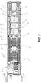
- FIG. 1illustrates a side perspective view of an internal layout/configuration of an example Direct-Interface Liquid-Cooled (DL) RIHS, according to one or more embodiments;
- DLDirect-Interface Liquid-Cooled
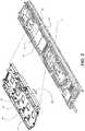
- FIG. 2illustrates a top view of an example LC node configured with a liquid cooling subsystem that includes a liquid-to-liquid manifold and cooling pipes for conductively cooling internal functional components, according to one or more embodiments;
- FIG. 3illustrates a front perspective view of the example LC node of FIG. 2 with a detailed view of a leak containment barrier, according to one or more embodiments;
- FIG. 4illustrates a rear perspective view of an example DL RIHS with a louvered rear door in a closed position over uncovered MLD conduits, according to one or more embodiments
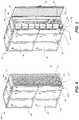
- FIG. 5illustrates a rear perspective view of an example DL RIHS with a louvered rear door in an open position, according to one or more embodiments
- FIG. 6illustrates the rear perspective view of FIGS. 4-5 with the pipe covers removed to expose modular liquid distribution (MLD) conduits, according to one or more embodiments;
- MLDmodular liquid distribution
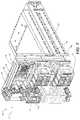
- FIG. 7illustrates a perspective view of a portion of a DL RIHS depicting example nodes, block radiators with Air-Liquid heat exchangers, and MLD conduits, according to one or more embodiments;
- FIG. 8illustrates a detailed block diagram of a DL RIHS configured with LC nodes arranged in blocks and which are cooled in part by a liquid cooling system having a rail comprised of MLD conduits, and in part by a subsystem of air-liquid heat exchangers, according to multiple embodiments;
- FIG. 9illustrates an expanded, more detailed view of the liquid interconnection between the node level heat exchange manifold, the block liquid manifold containing the air-liquid heat exchanger, and example MLDs of the liquid rail, according to multiple embodiments;
- FIG. 10illustrates a flow diagram of a method of assembling a DL RIHS, according to one or more embodiments
- FIG. 11illustrates a flow diagram of a method of containing leaks in a DL RIHS, according to one or more embodiments
- FIG. 12illustrates a table data structure of a listing of receiving node (server), block and rack-level sensor signals, according to one or more embodiments
- FIG. 13illustrates a table data structure of a listing sensor signals associated with rack-level scenarios and rack-level leak containment solutions, according to one or more embodiments
- FIG. 14illustrates a table data structure of a listing sensor signals with block-level scenarios and block-level leak containment solutions, according to one or more embodiments
- FIG. 15illustrates a table data structure of a listing of sensor signals with node-level scenarios and node-level leak containment solutions, according to one or more embodiments.
- FIG. 16illustrates a table data structure of a listing of sensor signals associated with sensors.
- the present disclosuregenerally provides a Direct-Interface Liquid-Cooled (DL) Rack Information Handling System (RIHS) providing liquid cooled (LC) information technology (IT) nodes containing heat-generating functional components and which are cooled at least in part by a liquid cooling subsystem.
- the RIHSincludes a rack configured with chassis-receiving bays in which is received a respective chassis of one of the LC nodes.
- Each LC nodeis configured with a system of conduits to receive direct intake/flow of cooling liquid to regulate the ambient temperature of the node.
- each LC nodeconfigured with a system of conduits, provides cooling to the components inside the node by conductively absorbing, via the cooling liquid, heat generated by the heat-generating functional components. The absorbed heat is removed (or transferred away) from within the node to outside of the node and/or the RIHS.
- the chassishas a leak containment barrier configured with a trough that underlays a portion of the system of conduits of the LC node and that forms a drain path to a drain port of the chassis.
- a Liquid Infrastructure Management Controller(LINC) implements a leak detection solution to avoid or mitigate damage to computing components.
- references within the specification to “one embodiment,” “an embodiment,” “embodiments”, or “one or more embodiments”are intended to indicate that a particular feature, structure, or characteristic described in connection with the embodiment is included in at least one embodiment of the present disclosure.
- the appearance of such phrases in various places within the specificationare not necessarily all referring to the same embodiment, nor are separate or alternative embodiments mutually exclusive of other embodiments.
- various featuresare described which may be exhibited by some embodiments and not by others.
- various requirementsare described which may be requirements for some embodiments but not other embodiments.
- rack-configured(as in RIHS) generally refers to the configuration of a large scale sever system within a physical rack having multiple chassis receiving rails for receiving specific sizes of information technology (IT) nodes, such as server modules, storage modules, and power modules.
- ITinformation technology
- the term nodegenerally refers to each separate unit inserted into a 1U or other height rack space within the rack.
- operational characteristics of the various IT nodescan be collectively controlled by a single rack-level controller.
- multiple nodescan be arranged into blocks, with each block having a separate block-level controller that is communicatively connected to the rack-level controller.
- an information handling systemmay include any instrumentality or aggregate of instrumentalities operable to compute, classify, process, transmit, receive, retrieve, originate, switch, store, display, manifest, detect, record, reproduce, handle, or utilize any form of information, intelligence, or data for business, scientific, control, or other purposes.
- an information handling systemmay be a personal computer, a network storage device, or any other suitable device and may vary in size, shape, performance, functionality, and price.
- the information handling systemmay include random access memory (RAM), one or more processing resources such as a central processing unit (CPU) or hardware or software control logic, ROM, and/or other types of nonvolatile memory.
- Additional components of the information handling systemmay include one or more disk drives, one or more network ports for communication with external devices as well as various input and output (I/O) devices, such as a keyboard, a mouse, and a video display.
- the information handling systemmay also include one or more buses operable to transmit communications between the various hardware components.
- server nodesmultiple processing servers or server IHSs (referred to herein as server nodes) can be included within the single RIHS. Certain aspect of the disclosure then relate to the specific LC (sever or other) nodes and the functionality associated with these individual nodes or block-level groupings of nodes, while other aspects more generally relate to the overall DL RIHS containing all of the LC nodes.
- the disclosurealso includes the additional consideration that in addition to cooling the primary heat generating components of the rack, such as the processor, what is needed is a way to allow for cooling of secondary equipment within the rack, as well as auxiliary components that would further support utilizing the advantages of a fluid-to-fluid heat exchanger methodology. Additionally, the present disclosure provides a modular approach to utilizing an air-to-liquid heat exchanger with quick connection and scalability to allow the solution to be scalable in both 1U and 2U increments.
- FIG. 1illustrates a side perspective view of an internal layout/configuration of an example Direct-Interface Liquid-Cooled (DL) RIHS 100 configured with a plurality of LC nodes 102 , according to one or more embodiments.
- DL RIHSDirect-Interface Liquid-Cooled
- FIG. 1illustrates a side perspective view of an internal layout/configuration of an example Direct-Interface Liquid-Cooled (DL) RIHS 100 configured with a plurality of LC nodes 102 , according to one or more embodiments.
- DL RIHSDirect-Interface Liquid-Cooled
- RIHS 100includes rack 104 , which comprises a rack frame and side panels, creating a front-to-back cabinet within which a plurality of chassis receiving bays are vertically arranged and in which a chassis of a respective IT node 102 can be inserted.
- Rack 104includes certain physical support structures (not specifically shown) that support IT gear insertion at each node location. Additional description of the structural make-up of an example rack is provided in the description of FIGS. 2-4 , which follows.
- FIG. 1depicts an illustrative example of LC nodes 102 a - 102 j (collectively refer to as nodes 102 ), with each nodes 102 a - 102 i including heat-generating functional components 106 .
- RIHS 100also includes an infrastructure node 102 j and liquid filtration node 102 k , which do not necessarily include heat-generating functional components 106 that require liquid cooling, as the other LC nodes 102 a - 102 i .
- nodes 102 a - 102 b , and 102 e - 102 hinclude other components 108 that are not necessarily heat generating, but which are exposed to the same ambient heat conditions as the heat generating components by virtue of their location within the node.
- these other components 108can be sufficiently cooled by the direct-interface liquid cooling applied to the node and/or using forced or convective air movement, as described later herein.
- Each node 102is supported and protected by a respective node enclosure 107 .
- Nodes 102 a - 102 dare further received in node receiving bays 109 of a first block chassis 110 a of a first block 112 a .
- Nodes 102 e - 102 iare received in a second block chassis 110 of a second block 112 b .
- the nodes 102are vertically arranged.
- at least portions of the nodes 102may also be arranged horizontally while benefiting from aspects of the present innovation.
- nodes 102can be of different physical heights of form factors (e.g., 1U, 1.5U, 2U), and the described features can also be applied to nodes 102 having different widths and depths (into the rack), with some extensions made and/or lateral modifications to the placement of cooling subsystem conduits, as needed to accommodate the different physical dimensions.
- form factorse.g. 1U, 1.5U, 2U
- node 102 iis depicted as having a larger node enclosure 107 ′ (with corresponding different dimensions of heat-generating functional components 106 ′) of a different number of rack units in physical height (e.g., 2U) that differs from the heights (e.g., 1U) of the other nodes 102 a - 102 h and 102 j - 102 k .
- RIHS 100can include blocks 112 or nodes 102 selectably of a range of discrete rack units.
- different types of IT componentscan be provided within each node 102 , with each node possibly performing different functions within RIHS 100 .
- a given node 102may include one of a server module, a power module, a control module, or a storage module.
- the nodes 102can be individual nodes operating independent of each other, with the RIHS 100 including at least one rack-level controller (RC) 116 for controlling operational conditions within the RIHS 100 , such as temperature, power consumption, communication, and the like.
- RCrack-level controller
- Each node 102is then equipped with a node-level controller (NC) 118 that communicates with the rack-level controller 116 to provide localized control of the operational conditions of the node 102 .
- NCnode-level controller
- RIHS 100also includes block-level controllers (BCs) 114 , communicatively coupled to the rack-level controller 116 and performing block-level control functions for the LC nodes within the specific block.
- BCsblock-level controllers
- the nodes 102are arranged into blocks 112 , with each block 112 having one or more nodes 102 and a corresponding block-level controller 114 .
- the blocksdo not necessarily include the same number of nodes, and a block can include a single node, in some implementations.
- a Direct-Interface Liquid Cooling (DL) subsystem(generally shown as being within the RIHS and labelled herein as 120 ) provides direct-intake/flow of cooling liquid to heat-generating functional components 106 via a liquid rail 124 under the control of rack-level controller 116 , block-level controllers 114 , and/or node-level controllers 118 , in some embodiments.
- Rack-level controller 116controls a supply valve 126 , such as a solenoid valve, to allow cooling liquid, such as water, to be received from a facility supply 128 .
- the cooling liquidis received from facility supply 128 and is passed through liquid filtration node 102 l before being passed through supply conduit 130 of liquid rail 124 .
- Each block 112 a , 112 breceives a dynamically controlled amount of the cooling liquid via block-level dynamic control valve 132 , such as a proportional valve. Return flow from each block 112 a , 112 b can be protected from backflow by a block check valve 133 .
- the individual needs of the respective nodes 102 a - 102 d of block 112 acan be dynamically provided by respective node-level dynamic control valves 134 , controlled by the block-level controller 114 , which control can, in some embodiments, be facilitated by the node-level controllers 118 .
- the control valves 134can be shutoff valves for emergency shutoff for leaks rather than dynamically controlled for thermal optimization.
- each of the supply valve 126 and/or dynamic control valves 132 , 134can be individually closed to mitigate a leak.
- a check valve 136is provided between each node 102 a - 102 j and a return conduit 138 of the liquid rail 124 to prevent a backflow into the nodes 102 a - 102 j .
- the return conduit 138returns the cooling liquid to a facility return 140 .
- RIHS 100includes temperature sensors 101 that are each located within or proximate to each node 102 a - 102 j , with each temperature sensor 101 connected to the node-level controller 118 and/or the corresponding block-level controller 114 . Temperature sensors 101 operate in a feedback control loop of the liquid cooling system 122 to control the amount of liquid flow required to cool the nodes 102 a - 102 j .
- the rack-level controller 116can coordinate performance constraints to block-level controllers 114 and/or node-level controllers 118 that limit an amount of heat generated by the heat-generating functional components 106 to match a heat capacity of the flow of cooling liquid in DL subsystem 122 .
- the rack-level controller 116can coordinate cooling levels to block-level controllers 114 and/or node-level controllers 118 that in turn control the dynamic control valves 132 , 134 for absorption and transfer of the heat generated by the heat-generating functional components 106 by the DL subsystem 122 .
- support controllerssuch as a Liquid Infrastructure Management Controller (LIMC) 142 can perform management and operational testing of DL subsystem 122 .
- LIMC 142can monitor pressure sensors 144 and liquid sensors 146 to detect a leak, to validate operation of a dynamic control valves 132 , 134 or shut-off valves such as supply valve 126 .
- LIMC 142can perform closed-loop control of specific flow rates within the RIHS 100 .
- LIMCLiquid Infrastructure Management Controller
- DL nodes 102 a - 102 jcan include other components 108 such as a hard drive device (HDD) that does not require DL cooling but could be damaged by moisture from the DL subsystem 122 .
- a leak containment barrier 193is configured with a trough 194 that underlays a portion of the system of conduits 143 of the LC node 102 a - 102 j .
- the trough 194forms a drain path 191 to a drain port 195 of the chassis 110 .
- a leak control subsystem 196includes a cascading gutter structure of drain conduits 197 originating from each trough 194 of a respective LC node 102 a - 102 j of the RIHS 100 .
- An absorbent material 192can be positioned to absorb and hold at least an initial portion of any liquid that leaks in the leak containment barrier 193 .
- the trough 194can direct even a small, slow leak to accumulate in a low portion for detection purposes.
- the node-level liquid sensor 146is exposed to the absorbent material 192 to detect a presence of liquid within the absorbent material 192 .
- a pair of electrical conduits 146 a , 146 bcan be inserted within the absorbent material and separated by a volume of the absorbent material 192 .
- An electrical currentpasses from a first conduit 146 a to a second conduit 146 b only when the absorbent material has absorbed a minimum threshold supply of leaked fluid.
- LIMC 142is in communication with the at least one liquid sensor 146 that triggers a closing of one or more shutoff valve 132 , 134 in response to a corresponding liquid sensor 146 detecting a liquid leak in the RIHS 100 .
- LIMC 142is in communication with the node-level, block-level, and rack-level liquid sensors 146 .
- LIMC 142associates a leak with a containment solution 186 .
- LIMC 142triggers closure of one or more shutoff valves 126 , 132 , and 134 to effect the containment solution 186 in response to the detected presence of liquid in the collection structure.
- FIGS. 2-3illustrate example LC node 200 of example DL RIHS 100 of FIG. 1 having a node enclosure 207 insertable into a block chassis 210 .
- node 200is a server IHS that includes processing components or central processing units (CPUs), storage devices, and other components.
- LC node 200includes cooling subsystem (generally shown and represented as 220 ) that includes a liquid-to-liquid manifold 242 to cool heat-generating functional components 206 by heat transfer from liquid provided by node-level supply conduit 244 , and return conduit 246 , according to one or more embodiments.
- Node-level supply conduit 244 and return conduit 246are appropriately sized and architecturally placed relative to the other components and the dimensionality (i.e., width, height, and depth/length) of LC node 200 to permit sufficient cooling liquid to pass through the interior of LC the node 200 to remove the required amount of heat from LC node 200 in order to provide appropriate operating conditions (in terms of temperature) for the functional components located within LC node 200 .
- Liquid-to-liquid manifold 242can include CPU cold plates 248 and voltage regulator cold plates 250 .
- a sled assembly grab handle 252can be attached between CPU cold plates 248 for lifting LC node 200 out of block chassis 210 .
- a return-side check valve 254 of the return conduit 246can prevent facility water from back-feeding into LC node 200 such as during a leak event.
- Flex hose links 256 in each of node-level supply conduit 244 and return conduits 246can reduce insertion force for sleds into block chassis 210 .
- Sled emergency shutoff device 234 interposed in the supply conduit 244can be a solenoid valve that closes in response to input from a hardware circuit during a sled-level leak detection event.
- node-level carrier 258 received in node enclosure 207can incorporate the leak containment barrier 293 to protect storage device 262 .
- LC node 200is oriented horizontally and is viewed from above.
- node-level carrier 258is configured to route leaked cooling liquid away from storage device 262 when oriented vertically.
- support surface 294 of node-level carrier 258incorporates a vibration absorbing material that can be integral to structural portions of the node-level carrier 258 .
- top vibration absorbing component 295such as a double-sided, adhesive backed, foam strip
- bottom vibration absorbing component 296such as a double-sided, adhesive backed, foam strip
- the vibration absorbing materialisolates sources of vibration to prevent the vibration from constructively amplifying to the point of impairing performance or damaging IT equipment.
- a storage drive 262can include a disk drive that creates a vibration during a repeated sequence of sector reads or writes.
- the liquid cooling systemcan include vibrations originating from movement/flow of the fluid moving and/or flow volume control.
- air moverscan create vibrations. With these vibration absorbing materials integrated into the design, node-level carrier 258 protects the storage devices 262 from vibrations originating at or otherwise delivered to storage devices 262 .
- FIGS. 4-6illustrate different exterior and rear views of an example assembled DL RIHS 400 .
- DL RIHS 400includes rack 404 , which is a physical support structure having an exterior frame and attached side panels to create cabinet enclosure 464 providing interior chassis receiving bays (not shown) within which a plurality of individual node chasses (or sleds) 207 of functional IT nodes, such as LC node 200 of FIG. 2 , are received.
- the cooling liquidis received from a facility supply 128 (of FIG. 1 ) via below rack (e.g. ground level or below floor) connections 680 a .
- the cooling liquidis received via an above-rack (and possibly in ceiling) connections 680 b.
- FIGS. 4-6specifically illustrate exterior views of rack 404 of example DL RIHS 100 .
- rack 404includes opposing side panels 466 , attached to a top panel 468 (and bottom panel—not shown) to create the main cabinet enclosure 464 that includes multiple chassis receiving bays for housing LC nodes 102 / 200 .
- the created cabinet enclosure 464includes a front access side (not shown) and a rear side.
- the front access sideprovides access to the chassis receiving bays created within the main cabinet enclosure 464 for receiving LC nodes 102 (of FIG. 1 ) into rack 404 .
- Attached to the rear ends of the main opposing side panels 466are opposing side panel extensions 472 .
- a louvered rear door 474is hinged (or otherwise attached) to one of the side panel extensions 472 and includes a latching mechanism for holding the door 474 in a closed position, where in a closed position is relative to the otherwise open space extending laterally between opposing side panel extensions 472 .
- Side panel extensions 472 and louvered rear door 474provide an extension to main cabinet enclosure 464 for housing, covering/protecting, and providing access to the modular, scalable liquid rail 424 of a liquid cooling subsystem 422 that provides liquid cooling to each LC node 102 (of FIG. 1 ) inserted into the chassis of the main cabinet enclosure 464 .
- FIGS. 5-6illustrate an embodiment in which rear pipe covers 476 can protect portions of liquid rail 324 , and specifically Modular Liquid Distribution (MLD) conduits 478 , from inadvertent damage as well as containing any leaks from being directed at sensitive functional components 106 (of FIG. 1 ).
- FIG. 5illustrate that the rear pipe covers 476 can be vertically sized to correspond to MLD conduits 478 .
- FIG. 7illustrates a more detailed view of the internal makeup of the rails and other functional components of a cooling subsystem 722 of example RIHS 700 .
- cooling subsystem 722also includes air movers and/or other devices to provide for forced air cooling in addition to the direct interface liquid cooling.
- at least one fan module 782is rear mounted to a block liquid manifold 789 in which an air-to-liquid heat exchanger (or radiator) 788 is incorporated.
- the fan module 782provides air movement through the chassis 710 and/or node enclosure 708 of the node 702 as well as through the air-to-liquid heat exchanger 788 .
- Each block liquid manifold 789includes a supply bypass tube 790 and a return bypass tube 791 through which a dynamically determined amount of cooling liquid is directed into the respective node 702 while allowing a bypass flow to proceed to the next node/s 702 in fluid path of the intake flow.
- Fan module 782includes apertures 747 through which the supply and return bypass tubes 790 , 791 are extended, in one embodiment.
- Nodes 702are connected into the back side of the block liquid manifold with the ends of intake and exhaust liquid transfer conduits in sealed fluid connection with bypass tubes 790 and 791 respectively.
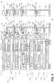
- FIG. 8illustrates a more detailed view of the interconnections of the liquid cooling subsystem, at a node level and rack level within an example DL RIHS 800 .
- RIHS 800is configured with LC nodes 802 a - 802 e arranged in blocks (e.g., block 1 comprising 802 a - 802 c ) and which are cooled in part by a liquid cooling system having a liquid rail comprised of MLD conduits, and in part by a subsystem of air-liquid heat exchangers, can be configured with heat-generating functional components 806 and that are cooled at least in part by a system of MLD conduits 878 a - 878 b , according to one or more embodiments.
- DL RIHS 800Illustrated within nodes 802 are heat-generating functional components 806 , such as processors, voltage regulators, etc., which emit heat during operation and or when power is applied to the component, such that the ambient temperature increases around the component, and within the node, and eventually within the block, and ultimately DL RIHS 800 , during standard operation.
- DL RIHS 800is configured with a DL subsystem 822 .
- DL subsystem 822includes a rack level network of liquid propagating pipes, or conduits that are in fluid communication with individual node level networks of liquid propagating conduits.
- DL subsystem 822collectively facilitates heat absorption and removal at the component level, the node level, the block level, and/or the rack level.
- the rack-level network of conduitsincludes a modular arrangement of a liquid rail 824 formed by more than one node-to-node MLD conduit 878 a - 878 b spanning (or extending) between LC nodes 802 provisioned in rack 804 .
- a block chassis 810is received in a block chassis receiving bay 870 a of rack 804 .
- a first node 802 a received in a first node receiving bay 809 a of the rack 804has a vertical height of one rack unit (1U).
- a rack unit, U or RU as a unit of measure,describes the height of electronic equipment designed to mount in a 19-inch rack or a 13-inch rack.
- the 19 inches (482.60 mm) or 13 inches (584.20 mm) dimensionreflects the horizontal lateral width of the equipment mounting-frame in the rack including the frame; the width of the equipment that can be mounted inside the rack is less.
- one rack unitis 1.75 inches (44.45 mm) high.
- a second node 802 b received in a second node receiving bay 809 b of the rack 104 (of FIG. 1 )has a vertical height of 1U.
- a third node 802 c received in a third node receiving bay 809 c of the rack 804has a vertical height of 1U.
- a fourth node 802 d , infrastructure node 802 bis received in a second block chassis receiving bay 870 b of rack 804 and has a vertical height of 1U.
- Infrastructure node 802 bcan contain functional components such as a rack-level controller 816 .
- a fifth node 802 eis received in a third chassis receiving bay 870 c and has a vertical height of 2U.
- a sixth node 802 fwhich provides a Rack Filtration Unit (RFU) 871 , is received in a fourth block chassis receiving bay 870 d of the rack 804 .
- Infrastructure node 802 and RFU 871are examples of nodes 802 that may not require liquid cooling.
- a cascading liquid containment structure 803is received in a fifth chassis receiving bay 870 e and includes liquid sensor 897 .
- MLD conduits 878 a of 1Ucan be used to connect nodes of 1U vertical spacing. Because of the additional 1U separation of LC nodes 802 c and 802 e by inclusion of infrastructure node 802 d , MLD conduit 878 b between the third and fifth nodes 802 c - 802 d is dimension 2U to accommodate the increased spacing. MLD conduits 878 a - 878 b can thus support different heights (1U to NU) of IT components.
- Each MLD conduit 878 a - 878 bincludes first and second terminal connections 883 , 884 attached on opposite ends of central conduit 885 that is rack-unit dimensioned to seal to a port of LC node 802 and enable fluid transfer between a port of a selected LC node 802 and a port of an adjacent LC node 802 .
- facility supply 828 and facility return 840are respectively located at the intake end of liquid rail 824 and the exhaust end of liquid rail 824 .
- the actual location of facility supply 828 and facility return 840can be reversed.
- facility supply 828 and facility return 840can be located above the RIHS 800 or both conduits can be located on opposite sides of the RIHS 800 in alternate embodiments.
- Liquid cooling subsystem 822includes a liquid infrastructure manager controller (LIMC) 842 which is communicatively coupled to block liquid controllers (BLCs) 887 to collectively control the amount of cooling liquid that flows through the RIHS 800 and ultimately through each of the nodes 802 in order to effect a desired amount of liquid cooling at the component level, node level, block level, and rack level.
- LIMC 842 and BLCs 887are depicted as separate components.
- the liquid control features of the LIMC 842 and BLCs 887can be incorporated into one or more of the rack-level controller 816 , block-level controllers 820 , and the node-level controllers 818 . As illustrated in FIG.
- each of the LIMC 842 and BLCs 887are connected to and respectively control the opening and closing of flow control valves that determine the amount of flow rate applied to each block and to each node within the specific block.
- one of LIMC 842 and BLC 887causes a specific amount of liquid to be directly injected into the intake conduits of the LC node 802 , which forces the cooling liquid through the system of conduits within the LC node 802 to the relevant areas and/or functional components/devices inside the nodes 802 to absorb and remove heat away from the inside of the node and/or from around the components within the node.
- DL cooling subsystem 822can include a plurality of air-to-liquid (or liquid-to-air) heat exchangers 888 that facilitate the release of some of the heat absorbed by the exhaust liquid to the surrounding atmosphere around the RIHS 100 (of FIG. 1 ).
- Air-to-liquid heat exchangers 888can be integral to block liquid manifold 889 that, along with the MLD conduits 878 a - 878 b , form scalable liquid rail 824 .
- One aspect of the present disclosureis directed to providing scalable rack-mounted air-to-liquid heat exchanger 888 for targeted heat rejection of rack-mounted equipment to DL cooling subsystem 822 .
- Hot air 899 from auxiliary components, such as storage device 808would be pushed through the air-to-liquid heat exchanger 888 , and the resulting energy would transfer to liquid rail 824 and be rejected to a facility cooling loop, represented by the facility return 840 .
- RIHS 800can include variations in LC node 802 that still maintain uniformity in interconnections along liquid rail 824 formed by a chassis-to-chassis modular interconnect system of MLD conduits 878 a - 878 b .
- cooling subsystem 822 of the RIHS 800allows each block chassis 810 to be a section of a scalable manifold, referred herein as liquid rail 824 , eliminating the need for a rack manifold.
- the scalability of liquid rail 824enables flexible configurations to include various permutations of server and switch gear within the same rack (rack 804 ).
- MLD conduits 878 a - 878 bcan comprise standardized hoses with sealable (water tight) end connectors.
- the rack liquid flow networkcan encompass 1 to N IT chassis without impacting rack topology, space constraints, and without requiring unique rack manifolds.
- the MLD conduitsare arranged in a pseudo daisy chain modular configuration, which allows for unplugging of one MLD conduit from one rack level without affecting liquid flow to and cooling of other rack levels.
- Block chassis 810 or node enclosure 807 of each LC node 102provides the intake and exhaust conduit connections to engage to respective terminals of MLD conduits 878 a - 878 b within the MLD network provided by liquid rail 824 .
- node enclosure 807would be a sled tray, and each block would then include more than one sled tray received into block chassis 810 , forming the extensions of block liquid manifold 889 .
- the node enclosure 807can be a single node chassis such as one of nodes 802 c - 802 f.
- Supply and return bypass tubes 890 , 891 of each block liquid manifold 889are connected by MLD conduits 878 a - 878 b to form supply rail conduit 830 and return rail conduit 838 .
- FIG. 8illustrates the return rail conduit 838 separately.
- Liquid rail 824enables multiple types of devices to be coupled together, each receiving an appropriately controlled portion of cooling liquid capacity.
- liquid cooling subsystem 822is passively pressurized by attaching MLD supply conduit 892 a to facility supply 828 and an MLD return conduit 892 b to facility return 840 .
- Liquid flow from supply rail conduit 830 to return rail conduit 838 of liquid rail 824can be controlled based upon factors such as a temperature of the liquid coolant, detected temperature within LC nodes 802 , air temperature inside or outside of DL RIHS 800 , etc.
- the scalable rack manifold provided by liquid rail 824is formed in part by MLD conduits 878 a - 878 b that run vertically in the back of the RIHS 800 with quick disconnects on the front and rear face of block liquid manifold 889 that allows for IT/infrastructure equipment respectively to be plugged into both front and back sides of the block liquid manifold 889 .
- LC nodes 802such as server modules, can plug into the front side and fan modules 882 can plug onto the back side of block liquid manifold 889 .
- Cooling subsystem 822can support an embedded liquid-to-liquid heat exchanger manifold 841 , such as in LC node 802 c .
- Node liquid-to-liquid heat exchangersare provided for rejecting heat from one fluid source to a secondary source.
- One aspect of the present disclosuresolves the problems that many shared-infrastructure IT systems (e.g., blade chassis) do not have adequate space to accommodate a liquid-to-liquid heat exchanger. Unlike with generally-known systems that rely upon liquid heat transfer having to exchange heat with an external liquid-to-liquid heat exchanger, the present disclosure enables on-rack liquid-to-liquid heat exchanger that does not require any of the vertical chassis space.
- One aspect of the present disclosureprovides embedded heat exchanger manifold 841 having a common heat transfer plate and a shared bulk header to create a combined liquid distribution manifold that includes a secondary liquid coolant for absorbing heat through the shared bulk header.
- the combined embedded heat exchanger manifold 841rejects heat within shared node enclosure 807 such as node 802 c to a secondary liquid coolant.
- Internal node supply 844 and return conduits 846 of a manifold built on top of a heat exchanger coreallow heat transport within manifold 841 .
- closed system pump 898can use a first coolant to cool a high thermal energy generating functional component such as a CPU or voltage regulator.
- liquid cooling subsystem 822also includes a filtration system or unit 871 , which prevents chemical impurities and particulates from clogging or otherwise damaging the conduits as the fluid passes through the network of conduits.
- liquid cooling subsystem 822provides RFU 871 in fluid connection with the intake pipes from facility supply 828 .
- RFU 871includes a sequenced arrangement of liquid filters within a full-sized sled that can be removably inserted by an end user into one of the receiving slots of rack 804 .
- the RFU 871is located on an infrastructure sled having rack-level controllers and other rack-level functional components.
- the entirety of the sledis filed with components associated with RFU 871 .
- the RFU 871may occupy the entire area of one vertical slot/position within the chassis.
- Alternate locations of the RFU 871can also be provided, in different embodiments, with an ideal location presenting the intake port of the RFU 871 in close proximity to a connection to facility supply 828 to directly receive the facility supply 828 prior to the liquid being passed into the remainder of the conduits of the liquid cooling subsystem 822 . It is appreciated that if the system was capable of completing all heat exchange within the rack, then sealing the rack would be feasible and would reduce and/or remove any requirements for filtration and/or allocation of rack space for RFU 871 .
- node-level HDD carrier or leak containment barrier 893can include a trench/gutter system or trough 894 .
- the gutter systemcan also incorporate an absorbent material that can accumulate sufficient amounts of liquid from small leaks to enable external sensing of the leak.
- the leak containment barrier 893can also be thermally conductive to serve as a heat sink for components such as storage devices 808 .
- another leak detection solution that can be incorporated into the LC node 802involves use of a solenoid to create an event when additional current is applied, due to water pooling around the solenoid. Barriers on leak containment barrier 893 can be specifically designed to contain a liquid leak and assist in funneling the liquid through the gutter system.
- Liquid rail 824can also be provided with leak containment and detection.
- removable pipe covers 876are sized to be mounted around respective MLD conduits 878 a - 878 b and can include liquid sensors 897 for automatic alerts and shutdown measures.
- DL RIHS 800further incorporates a node-level liquid containment structure 803 with a cascading drain runoff tubing network 896 to a rack-level cascading liquid containment structure 895 .
- the DL RIHS 800further incorporates leak detection command such as partial or complete automated emergency shutdown.
- Liquid sensors (LS) 897 at various cascade levelscan identify affected portions of DL RIHS 800 . Containment and automatic shutoff can address the risks associated with a leak developing in the DL cooling system 822 .
- FIG. 9illustrates a more detailed view of DL subsystem 920 associated with example DL RIHS 900 .
- each LC node 902 a , 902 bincludes chassis 910 received in a respective chassis-receiving bay 970 of rack 904 .
- Each LC node 902 a , 902 bcontains heat-generating functional components 906 .
- Each LC node 902 a , 902 bis configured with a system of internal supply conduit 944 and return conduit 946 , associated with embedded heat exchanger manifold 941 .
- Embedded heat exchanger manifold 941receives direct intake/flow of cooling liquid to regulate the ambient temperature of LC node 902 a , 902 b .
- a node-level dynamic control valve 934 and node-level return check valve 936control an amount of normal flow and provide shutoff and/or otherwise mitigate a leak.
- Cooling subsystem 920provides cooling to heat-generating functional components 906 inside the LC node 902 a , 902 b by removing heat generated by heat-generating functional components 906 .
- Liquid rail 924is formed from more than one node-to-node, MLD conduit 978 between more than one LC node 902 a , 902 b within in rack 904 .
- MLD conduits 978includes first terminal connection 983 and second terminal connection 984 .
- First terminal connection 983 and second terminal connection 984are attached on opposite ends of central conduit 985 .
- Central conduit 985is rack-unit dimensioned to directly mate and seal to and enable fluid transfer between a selected pair of rail supply ports 917 and/or rail return ports 919 of a selected LC node 902 a and an adjacent LC node 902 b.
- the cooling subsystem 920includes block liquid manifolds 989 mountable at a back side of the rack 904 .
- Each block liquid manifoldhas at least one rail supply port 917 and at least one rail return port 919 on an outside facing side of the block liquid manifold 989 .
- the at least one rail supply port 917 and the at least one rail return port 919respectively communicate with at least one block supply port 921 and a block return port 923 on an inside facing side of the block liquid manifold 989 .
- LC nodes 902are insertable in receiving bays 970 of rack 904 corresponding to locations of the mounted block liquid manifolds 989 .
- Block supply ports 921 and block return ports 923 of the LC nodes 902 and an inside facing portion of the corresponding block liquid manifold 989are linearly aligned.
- the linear alignmentenables direct sealing, for fluid transfer, of the lineally aligned inside manifold supply ports 925 and return ports 927 to the inside facing portion of the block liquid manifold 989 .
- block supply port 921 sealed to the internal manifold supply port 925communicates via supply bypass tube 990 to two rail supply ports 917 .
- Block return port 923 sealed to internal manifold return port 927communicates via return bypass tube 991 of the respective block liquid manifold 989 to two rail return ports 919 .
- Fan modules 982 mounted respectively onto back of block liquid manifold 989have apertures to expose rail supply and return ports 917 , 919 . Additionally, fan modules 982 draw hot air 999 from LC nodes 902 through an air-liquid heat exchanger 988 in block liquid manifold 989 .
- supply liquid conduit 992 ais attached for fluid transfer between facility supply 928 and rail supply port 917 of block liquid manifold 989 of RIHS 900 .
- a return liquid conduit 992 bcan be attached for fluid transfer between rail return port 919 of block liquid manifold 989 and facility return 940 .
- FIG. 9further illustrates that the fluid connection to facility supply 928 includes RFU 971 .
- RFU 971is received in bay 970 of rack 904 and includes one of two input ports 929 connected via supply liquid conduit 992 a to facility supply 928 .
- the RFU 971includes one of two output ports 931 that is connected to MLD conduit 978 of supply rail conduit 930 .
- Liquid rail 924also includes return rail conduit 938 .
- RFU 971controls two external emergency shutoff valves 933 for flow received from the input port 929 that is provided respectively via hot-pluggable disconnects 935 to two replaceable filtration subunits (“filters”) 937 .
- the flow of cooling liquidflows in parallel to two replaceable filtration subunits 937 , automatically diverting to the other when one is removed for replacing. Thereby, filtration and cooling of RIHS 900 can be continuous.
- Back-flowis prevented by check valve 939 that allows normal flow to exit to output port 931 .
- Differential pressure sensor 947measures the pressure drop across filters”) 937 and provides an electrical signal proportional to the differential pressure.
- a LINC 942can determine that one filter 937 is clogged if the differential pressure received from differential pressure sensor 944 falls below a pre-determined value.
- RIHS 900can provide hot-pluggable server-level liquid cooling, an integrated leak collection and detection trough, and an automatic emergency shut-off circuit.
- RIHS 900can provide embedded air-to-liquid heat exchange, and dynamic liquid flow control.
- RIHS 900can provide facility-direct coolant delivery, a scalable rack fluid network, a rack filtration unit, and automated rack flow balancing, and a service mode.
- liquid rail 924includes a series of secondary conduits, such as a supply divert conduit 997 and a return divert conduit 998 , that provides a by-pass fluid path for each of MLD conduits 978 .
- divert conduit 997allows for the removal of corresponding MLD conduit 978 , thus removing the flow of cooling liquid to the particular block of nodes, without interrupting the flow of cooling liquid to the other surrounding blocks of computer gear.
- a particular MLD conduit 978can be replaced due to a leak.
- a block liquid manifold 989can be replaced.
- divert conduits 997 , 998thus enables rapid servicing and maintenance of block liquid manifold 989 and/or nodes within block chassis without having to reconfigure the MLD conduits 978 .
- the RIHS 900can continue operating as cooling liquid continues to be provided to the remainder of the blocks that are plugged into the liquid rail. Re-insertion of the MLD conduit 978 then reconnects the flow of cooling liquid to the block for normal cooling operations, and shuts off the diverted flow of cooling liquid.
- the MLD conduits 978provide a quick disconnect feature that interrupts flow when not fully engaged to a respective port 917 , 919 , 921 , 923 .
- Disconnection of an MLD conduit 978interrupts flow in a primary portion of the liquid rail 924 for either supply or return, shifting flow through one or more divert conduits 997 to provide cooling liquid to the other block liquid manifolds 989 .
- a manual or active shutoff valvecan interrupt flow on either or both of the primary or divert portions of the liquid rail 924 .
- each LC node 902can receive liquid cooling service from a corresponding block liquid manifold 928 as illustrated by FIG. 9 .
- one or more block liquid manifolds 928provide liquid cooling service to a block chassis 910 that in turn quick connects to more than one LC node 902 a , 902 b .
- a node-receiving liquid inlet port 911 and a node-receiving liquid outlet port 913are located at the rear section of one node-receiving slot 909 a , 909 b and positioned to be inwardly facing for blind mating to a node inlet and outlet ports 915 , 917 of an LC node 902 a , 902 b inserted in the one node-receiving slot 909 a , 909 b .
- the system of internal supply conduit 944 and return conduit 946supply cooling liquid through the node enclosure 907 .
- the supply conduit 944extends from a node inlet coupling 915 , which in an exemplary embodiment is a male inlet coupling.
- the return conduit 946terminates in a node outlet coupling 917 , which in an exemplary embodiment is a male outlet coupling.
- the node inlet port 915 and the node outlet port 917are positioned in an outward facing direction at a rear of the node enclosure 907 .
- the node inlet port 915 and the node outlet port 917are aligned to releasably seal to the respective inlet liquid port and outlet liquid port in the node-receiving slot 909 a , 909 b , for fluid transfer through the system of conduits 944 , 946 .
- a block supply plenum 975 and return plenum 976can communicate for fluid transfer between the block liquid manifold 989 and each of the supported LC nodes 902 a , 902 b . Modulation or shutoff of cooling liquid at the block level can also be incorporated into the block supply plenum 975 and return plenum 976 .
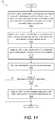
- FIG. 10illustrates a method 1000 of assembling a DL RIHS.
- the method 1000includes inserting a leak containment barrier in a node enclosure (block 1002 ).
- the method 1000includes provisioning the node enclosure with heat-generating functional components (block 1004 ).
- the method 1000includes attaching the system of conduits supplying cooling liquid through the node enclosure.
- the system of conduitsincludes a supply conduit extending from the node inlet coupling and a return conduit terminating in the node outlet coupling.
- a trough of the leak containment barrierunderlays a portion of the system of conduits of the LC node and forms a drain path to a drain port of the node enclosure (block 1006 ).
- the method 1000includes mounting the LC node insertably received in the one node-receiving slot of a rack having one or more node-receiving slots.
- Each slothas a front opening for node insertion and a rear section opposed to the front access for blind mating of the node inlet and outlet ports to a node-receiving liquid inlet port and a node-receiving liquid outlet port located at the rear section of one node-receiving slot.
- the node-receiving liquid inlet port and the node-receiving liquid outlet portare positioned to be inwardly facing to the LC node inserted in the one node-receiving slot (block 1008 ). Then method 1000 ends.
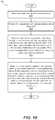
- FIG. 11illustrates a method 1100 of containing leaks in a DL RIHS.
- the method 1100includes a controller communicating with a liquid sensor to detect liquid received in a leak containment barrier that is leaked in a trough from a received system of conduits internal to a node enclosure of an LC node that is provisioned with a heat-generating computing component (block 1102 ).
- the method 1100includes, identifying which levels of leak detection sensors detected the leak from among a node-level sensors, one or more block-level sensors, and the rack-level sensor (block 1104 )
- an absorbent materialis positioned to absorb and hold at least an initial portion of any liquid that leaks in the leak containment barrier.
- the node-level liquid sensoris exposed to the absorbent material to detect a presence of liquid within the absorbent material.
- method 1100includes triggering shutoff of at least a lowest level shutoff valve that supplies cooling liquid to an area monitored by the identified sensor (block 1106 ).
- the method 1100includes determining whether the containment solution applied was effective by determining whether an additional leak detection signal is subsequently received at a higher level sensor (decision block 1108 ). In response to determining the containment solution was effective in decision block 1108 , the method 1100 ends. In response to determining the containment solution was not effective in decision block 1108 , the method 1100 includes triggering a shutoff valve that supplies cooling liquid to the higher level area monitored by the higher level sensor (block 1110 ). Then method 1100 ends.
- the method 1000can include receiving node (server), block and rack-level sensor signals as listed in Table 1200 in FIG. 12 .
- method 1000can associate the sensor signals with rack-level scenarios and rack-level leak containment solutions as listed in Table 1300 in FIG. 13 .
- method 1000can associate the sensor signals with block-level scenarios and block-level leak containment solutions as listed in Table 1400 in FIG. 14 .
- the method 1000can associate the sensor signals with node-level scenarios and node-level leak containment solutions as listed in Table 1500 in FIG. 1500 .
- method 1000can receive the sensor signals from sensors listed in Table 1600 in FIG. 16 .
- one or more of the methodsmay be embodied in an automated manufacturing system or automated controller that performs a series of functional processes. In some implementations, certain steps of the methods are combined, performed simultaneously or in a different order, or perhaps omitted, without deviating from the scope of the disclosure.
- the method blocksare described and illustrated in a particular sequence, use of a specific sequence of functional processes represented by the blocks is not meant to imply any limitations on the disclosure. Changes may be made with regards to the sequence of processes without departing from the scope of the present disclosure. Use of a particular sequence is therefore, not to be taken in a limiting sense, and the scope of the present disclosure is defined only by the appended claims.
- One or more of the embodiments of the disclosure describedcan be implementable, at least in part, using a software-controlled programmable processing device, such as a microprocessor, digital signal processor or other processing device, data processing apparatus or system.
- a computer program for configuring a programmable device, apparatus or system to implement the foregoing described methodsis envisaged as an aspect of the present disclosure.
- the computer programmay be embodied as source code or undergo compilation for implementation on a processing device, apparatus, or system.
- the computer programis stored on a carrier device in machine or device readable form, for example in solid-state memory, magnetic memory such as disk or tape, optically or magneto-optically readable memory such as compact disk or digital versatile disk, flash memory, etc.
- the processing device, apparatus or systemutilizes the program or a part thereof to configure the processing device, apparatus, or system for operation.
Landscapes
- Engineering & Computer Science (AREA)
- Physics & Mathematics (AREA)
- General Engineering & Computer Science (AREA)
- Thermal Sciences (AREA)
- Microelectronics & Electronic Packaging (AREA)
- Computer Hardware Design (AREA)
- Theoretical Computer Science (AREA)
- Human Computer Interaction (AREA)
- General Physics & Mathematics (AREA)
- Cooling Or The Like Of Electrical Apparatus (AREA)
- Aviation & Aerospace Engineering (AREA)
Abstract
Description
Claims (10)
Priority Applications (1)
| Application Number | Priority Date | Filing Date | Title |
|---|---|---|---|
| US16/240,065US10729039B2 (en) | 2015-12-21 | 2019-01-04 | Liquid cooled rack information handling system having storage drive carrier for leak containment and vibration mitigation |
Applications Claiming Priority (4)
| Application Number | Priority Date | Filing Date | Title |
|---|---|---|---|
| US201562270563P | 2015-12-21 | 2015-12-21 | |
| US201562270575P | 2015-12-21 | 2015-12-21 | |
| US15/049,074US10206312B2 (en) | 2015-12-21 | 2016-02-20 | Liquid cooled rack information handling system having storage drive carrier for leak containment and vibration mitigation |
| US16/240,065US10729039B2 (en) | 2015-12-21 | 2019-01-04 | Liquid cooled rack information handling system having storage drive carrier for leak containment and vibration mitigation |
Related Parent Applications (1)
| Application Number | Title | Priority Date | Filing Date |
|---|---|---|---|
| US15/049,074DivisionUS10206312B2 (en) | 2015-12-21 | 2016-02-20 | Liquid cooled rack information handling system having storage drive carrier for leak containment and vibration mitigation |
Publications (2)
| Publication Number | Publication Date |
|---|---|
| US20190141862A1 US20190141862A1 (en) | 2019-05-09 |
| US10729039B2true US10729039B2 (en) | 2020-07-28 |
Family
ID=59066654
Family Applications (3)
| Application Number | Title | Priority Date | Filing Date |
|---|---|---|---|
| US15/049,074ActiveUS10206312B2 (en) | 2015-12-21 | 2016-02-20 | Liquid cooled rack information handling system having storage drive carrier for leak containment and vibration mitigation |
| US15/167,981Active2036-06-30US10143114B2 (en) | 2015-12-21 | 2016-05-27 | Liquid cooled rack information handling system having leak management system |
| US16/240,065ActiveUS10729039B2 (en) | 2015-12-21 | 2019-01-04 | Liquid cooled rack information handling system having storage drive carrier for leak containment and vibration mitigation |
Family Applications Before (2)
| Application Number | Title | Priority Date | Filing Date |
|---|---|---|---|
| US15/049,074ActiveUS10206312B2 (en) | 2015-12-21 | 2016-02-20 | Liquid cooled rack information handling system having storage drive carrier for leak containment and vibration mitigation |
| US15/167,981Active2036-06-30US10143114B2 (en) | 2015-12-21 | 2016-05-27 | Liquid cooled rack information handling system having leak management system |
Country Status (1)
| Country | Link |
|---|---|
| US (3) | US10206312B2 (en) |
Cited By (8)
| Publication number | Priority date | Publication date | Assignee | Title |
|---|---|---|---|---|
| TWI803276B (en)* | 2021-09-01 | 2023-05-21 | 廣達電腦股份有限公司 | Rack system, liquid cooling system, and method for controlling liquid cooling system leaks |
| US11729950B2 (en) | 2021-04-01 | 2023-08-15 | Ovh | Immersion cooling system with dual dielectric cooling liquid circulation |
| US20240023276A1 (en)* | 2022-07-13 | 2024-01-18 | Dell Products, L.P. | Rack-based management of leaks in liquid cooled information handling systems |
| US11924998B2 (en) | 2021-04-01 | 2024-03-05 | Ovh | Hybrid immersion cooling system for rack-mounted electronic assemblies |
| US12120846B2 (en) | 2021-04-01 | 2024-10-15 | Ovh | Immersion cooling systems for electronic components |
| US12137536B2 (en) | 2021-04-01 | 2024-11-05 | Ovh | Systems and methods for autonomously activable redundant cooling of a heat generating component |
| US12144145B2 (en) | 2021-04-01 | 2024-11-12 | Ovh | Data center rack system with integrated liquid and dielectric immersion cooling |
| TWI893409B (en) | 2023-03-16 | 2025-08-11 | 英華達股份有限公司 | Notebook computer and control method, and system thereof |
Families Citing this family (48)
| Publication number | Priority date | Publication date | Assignee | Title |
|---|---|---|---|---|
| US11249522B2 (en)* | 2016-06-30 | 2022-02-15 | Intel Corporation | Heat transfer apparatus for a computer environment |
| US10299413B2 (en)* | 2017-02-21 | 2019-05-21 | Baidu Usa Llc | Modular self-aligning liquid heat removal coupling system for electronic racks |
| US10485137B2 (en)* | 2017-03-01 | 2019-11-19 | Microsoft Technology Licensing, Llc | Cooling device for fluid submersion of electronics |
| US10765039B2 (en)* | 2017-05-25 | 2020-09-01 | Intel Corporation | Two-phase liquid-vapor computer cooling device |
| US10188017B2 (en) | 2017-05-31 | 2019-01-22 | Microsoft Technology Licensing, Llc | Server cooling fluid inlet and pickup placement in submerged cooling enclosures |
| CN107979955B (en)* | 2017-11-24 | 2020-06-30 | 北京百度网讯科技有限公司 | A modular liquid-cooled server chassis |
| CN107846822A (en)* | 2017-11-26 | 2018-03-27 | 北京中热能源科技有限公司 | A kind of electronic equipment cooling system |
| US10375863B2 (en)* | 2017-11-28 | 2019-08-06 | Dell Products, L.P. | Liquid cooled chassis |
| CN108124409B (en)* | 2017-12-19 | 2021-03-23 | 漳州科华技术有限责任公司 | Server liquid cooling system |
| US10928867B2 (en)* | 2018-02-06 | 2021-02-23 | Hewlett Packard Enterprise Development Lp | Cooling distribution unit flow rate |
| US10736240B2 (en)* | 2018-05-24 | 2020-08-04 | Baidu Usa Llc | High reliability cooling module design for IT and data center liquid cooling |
| US10925190B2 (en)* | 2018-06-04 | 2021-02-16 | Baidu Usa Llc | Leak detection and response system for liquid cooling of electronic racks of a data center |
| US11051425B2 (en)* | 2018-08-31 | 2021-06-29 | Te Connectivity Corporation | Thermal management for communication system |
| US10856055B2 (en)* | 2019-03-20 | 2020-12-01 | Mellanox Technologies, Ltd. | Apparatuses for improved thermal performance of dynamic network connections |
| US10859461B2 (en)* | 2019-05-01 | 2020-12-08 | Dell Products, L.P. | Method and apparatus for digital leak detection in liquid-cooled information handling systems |
| CN110568911B (en)* | 2019-09-05 | 2021-04-23 | 英业达科技有限公司 | Server |
| US11802807B2 (en) | 2019-09-25 | 2023-10-31 | Dell Products L.P. | Leak detection apparatus for an information handling system |
| US12200913B2 (en)* | 2020-02-21 | 2025-01-14 | Nvidia Corporation | Intelligent and integrated liquid-cooled rack for datacenters |
| TWI743734B (en)* | 2020-04-08 | 2021-10-21 | 神雲科技股份有限公司 | Water-cooled server leakage protection method |
| US11310938B2 (en)* | 2020-06-09 | 2022-04-19 | Dell Products, L.P. | Leak sensor drip tray |
| WO2022047360A1 (en)* | 2020-08-31 | 2022-03-03 | Hoffman Enclosures Inc. | Mounting interface for liquid manifold and electronics rack |
| US11452237B2 (en)* | 2020-10-16 | 2022-09-20 | Hewlett Packard Enterprise Development Lp | Liquid cooling interconnect module of a computing system |
| US11778778B2 (en)* | 2020-11-03 | 2023-10-03 | Cmotion Technologies Limited | Liquid-cooled container equipment |
| US20240107707A1 (en)* | 2020-12-09 | 2024-03-28 | Saab Ab | Cooling system of an electronic module with a leakage control device |
| CN112783298B (en)* | 2021-04-12 | 2021-07-23 | 湖南兴天电子科技有限公司 | Air-cooled radiating modularization reinforcement computer |
| US12013193B2 (en)* | 2021-06-07 | 2024-06-18 | Baidu Usa Llc | Sectional architecture for fluid management and leakage sensors |
| US12127366B2 (en)* | 2021-06-15 | 2024-10-22 | Dell Products L.P. | Fan management system |
| US11729946B2 (en)* | 2021-08-31 | 2023-08-15 | Baidu Usa Llc | Electronics rack with leak segregation system |
| US11778777B2 (en)* | 2021-09-01 | 2023-10-03 | Baidu Usa Llc | Electronics rack distribution system with leaking detection unit |
| US12197190B2 (en)* | 2021-10-04 | 2025-01-14 | Dell Products, L.P. | Liquid cooling leakage abatement system and method of using the same |
| CN117135869A (en)* | 2022-05-20 | 2023-11-28 | 华为技术有限公司 | A heat dissipation device, connection structure and electronic equipment |
| US12203790B2 (en)* | 2022-07-07 | 2025-01-21 | Dell Products L.P. | Systems and methods for flow rate detection in a liquid cooling system |
| US12185496B2 (en)* | 2022-07-20 | 2024-12-31 | Dell Products, L.P. | Liquid cooling manifold for information technology equipment |
| US12405917B2 (en)* | 2022-07-27 | 2025-09-02 | Dell Products, L.P. | Chassis supporting interchangeable accelerator baseboards |
| US12317449B2 (en)* | 2022-08-02 | 2025-05-27 | Quanta Computer Inc. | Structure for detection and collection of leaked coolant |
| EP4152905B1 (en)* | 2022-08-18 | 2025-04-23 | Ovh | Immersion-cooled electronic device and cooling monitoring system for immersion-cooled electronic device |
| US12200898B2 (en) | 2022-10-20 | 2025-01-14 | Dell Products L.P. | System and method for managing component positioning and orientation in data processing systems |
| US12133356B2 (en) | 2022-10-20 | 2024-10-29 | Dell Products L.P. | System and method for managing retaining cooling components in data processing systems |
| US12200886B2 (en) | 2022-10-20 | 2025-01-14 | Dell Products L.P. | System and method for thermal management of removable components |
| US12317446B2 (en) | 2022-10-20 | 2025-05-27 | Dell Products L.P. | System and method for improving rate of air flow through data processing systems |
| US12174823B2 (en) | 2022-10-21 | 2024-12-24 | Dell Products L.P. | System and method to ensure data integrity of software defined storage system |
| WO2024091967A1 (en)* | 2022-10-24 | 2024-05-02 | Strategic Thermal Labs, Llc | Environmentally hardened cold plate for use in liquid cooling of electronic devices |
| WO2024091972A2 (en)* | 2022-10-24 | 2024-05-02 | Strategic Thermal Labs, Llc | Smart rack liquid cooling manifold system having integrated controller(s) providing server-level liquid telemetry monitoring, rack liquid flow control, and datacenter communicaton |
| US12101913B2 (en) | 2022-11-29 | 2024-09-24 | Dell Products L.P. | Variable topography heat sink fins |
| US12342500B2 (en)* | 2022-12-12 | 2025-06-24 | Quanta Computer Inc. | System and method for cooling electronic computing device with multiple-function pump |
| US12432879B2 (en)* | 2023-04-06 | 2025-09-30 | Lenovo Global Technology (United States) Inc. | Liquid cooling leak detection apparatus |
| TWI865182B (en)* | 2023-11-17 | 2024-12-01 | 宏碁股份有限公司 | Electronic device |
| US20250234483A1 (en)* | 2024-01-12 | 2025-07-17 | ZT Group Int’l, Inc. dba ZT Systems | Manifold system for computing assembly |
Citations (89)
| Publication number | Priority date | Publication date | Assignee | Title |
|---|---|---|---|---|
| US4698728A (en)* | 1986-10-14 | 1987-10-06 | Unisys Corporation | Leak tolerant liquid cooling system |
| US5414742A (en)* | 1993-11-10 | 1995-05-09 | Westinghouse Electric Corporation | Leak-detection system and method for detecting a leaking container |
| US5758607A (en) | 1995-05-26 | 1998-06-02 | Bayerische Motoren Werke Aktiengesellschaft | Cooling system having an electrically adjustable control element |
| US6305463B1 (en) | 1996-02-22 | 2001-10-23 | Silicon Graphics, Inc. | Air or liquid cooled computer module cold plate |
| US6462949B1 (en) | 2000-08-07 | 2002-10-08 | Thermotek, Inc. | Electronic enclosure cooling system |
| US6574104B2 (en) | 2001-10-05 | 2003-06-03 | Hewlett-Packard Development Company L.P. | Smart cooling of data centers |
| US20030101799A1 (en)* | 2001-11-30 | 2003-06-05 | Taiwan Semiconductor Manufacturing Co., Ltd. | Liquid leak detection |
| US20030128515A1 (en) | 2002-01-04 | 2003-07-10 | Faneuf Barrett M. | Chassis-level thermal interface component for transfer of heat from an electronic component of a computer system |
| US6775137B2 (en) | 2002-11-25 | 2004-08-10 | International Business Machines Corporation | Method and apparatus for combined air and liquid cooling of stacked electronics components |
| US6798660B2 (en) | 2003-02-13 | 2004-09-28 | Dell Products L.P. | Liquid cooling module |
| US20040221604A1 (en) | 2003-02-14 | 2004-11-11 | Shigemi Ota | Liquid cooling system for a rack-mount server system |
| US20050122685A1 (en) | 2003-12-03 | 2005-06-09 | International Business Machines Corporation | Cooling system and method employing multiple dedicated coolant conditioning units for cooling multiple electronics subsystems |
| US20050248922A1 (en) | 2004-05-07 | 2005-11-10 | International Business Machines Corporation | Cooling assembly for electronics drawer using passive fluid loop and air-cooled cover |
| US20060002080A1 (en)* | 2004-06-30 | 2006-01-05 | Javier Leija | Liquid cooling system including hot-swappable components |
| US7002799B2 (en) | 2004-04-19 | 2006-02-21 | Hewlett-Packard Development Company, L.P. | External liquid loop heat exchanger for an electronic system |
| US7013955B2 (en) | 2003-07-28 | 2006-03-21 | Thermal Corp. | Flexible loop thermosyphon |
| US20080067805A1 (en) | 2004-06-01 | 2008-03-20 | Nissan Motor Co., Ltd. | Fluid coupling |
| US7403384B2 (en) | 2006-07-26 | 2008-07-22 | Dell Products L.P. | Thermal docking station for electronics |
| US20080232064A1 (en) | 2007-03-22 | 2008-09-25 | Fujitsu Limited | Cooling system for information device |
| US20080276639A1 (en) | 2007-05-10 | 2008-11-13 | Stoddard Robert J | Computer cooling system |
| US7477514B2 (en) | 2007-05-04 | 2009-01-13 | International Business Machines Corporation | Method of facilitating cooling of electronics racks of a data center employing multiple cooling stations |
| US20090086428A1 (en) | 2007-09-27 | 2009-04-02 | International Business Machines Corporation | Docking station with hybrid air and liquid cooling of an electronics rack |
| US20090086432A1 (en) | 2007-09-27 | 2009-04-02 | International Business Machines Corporation | Docking station with closed loop airlfow path for facilitating cooling of an electronics rack |
| US20090126910A1 (en) | 2007-11-19 | 2009-05-21 | International Businiess Machines Corporation | Apparatus and method for facilitating servicing of a liquid-cooled electronics rack |
| US20090126909A1 (en) | 2007-11-19 | 2009-05-21 | International Business Machines Corporation | System and method for facilitating cooling of a liquid-cooled electronics rack |
| US20090165868A1 (en) | 2007-12-31 | 2009-07-02 | Pearson Steven L | Automated condensate drain line cleaning system, method, and kit |
| US20090201645A1 (en)* | 2008-02-13 | 2009-08-13 | Hitachi Plant Technologies, Ltd. | Cooling system for electronic equipment |
| US7599184B2 (en) | 2006-02-16 | 2009-10-06 | Cooligy Inc. | Liquid cooling loops for server applications |
| US20090259343A1 (en) | 2006-01-19 | 2009-10-15 | American Power Conversion Corporation | Cooling system and method |
| US20090262501A1 (en) | 2008-04-21 | 2009-10-22 | International Business Machines Corporation | Rack With Integrated Rear-Door Heat Exchanger |
| US7657347B2 (en) | 2008-02-15 | 2010-02-02 | International Business Machines Corporation | Temperature-based monitoring method and system for determining first and second fluid flow rates through a heat exchanger |
| US20100032142A1 (en) | 2008-08-11 | 2010-02-11 | Sun Microsystems, Inc. | Liquid cooled rack with optimized air flow rate and liquid coolant flow |
| US20100032140A1 (en) | 2008-08-06 | 2010-02-11 | Sun Microsystems, Inc. | Liquid cooled rack with optimized liquid flow path driven by electronic cooling demand |
| US20100103618A1 (en) | 2008-10-23 | 2010-04-29 | International Business Machines Corporation | Apparatus and method for facilitating pumped immersion-cooling of an electronic subsystem |
| US20100103614A1 (en) | 2008-10-23 | 2010-04-29 | International Business Machines Corporation | Apparatus and method for immersion-cooling of an electronic system utilizing coolant jet impingement and coolant wash flow |
| US20110075373A1 (en) | 2009-09-28 | 2011-03-31 | International Business Machines Corporation | System and method for standby mode cooling of a liquid-cooled electronics rack |
| US20110083621A1 (en) | 2009-06-18 | 2011-04-14 | Cummins Ip, Inc. | Apparatus, System, and Method for Reductant Line Heating Control |
| US20110112694A1 (en) | 2008-06-30 | 2011-05-12 | Bash Cullen E | Cooling Medium Distribution Over A Network Of Passages |
| US7944694B2 (en) | 2008-10-23 | 2011-05-17 | International Business Machines Corporation | Liquid cooling apparatus and method for cooling blades of an electronic system chassis |
| US7963119B2 (en) | 2007-11-26 | 2011-06-21 | International Business Machines Corporation | Hybrid air and liquid coolant conditioning unit for facilitating cooling of one or more electronics racks of a data center |
| US7990709B2 (en) | 2009-09-23 | 2011-08-02 | International Business Machines Corporation | Apparatus and method for facilitating cooling of an electronics rack |
| US8035972B2 (en) | 2009-07-31 | 2011-10-11 | Oracle America, Inc. | Method and apparatus for liquid cooling computer equipment |
| US8077462B2 (en) | 2009-09-02 | 2011-12-13 | International Business Machines Corporation | Stress relieved hose routing to liquid-cooled electronics rack door |
| US20110313576A1 (en)* | 2010-06-17 | 2011-12-22 | Mark Randal Nicewonger | System and method for flowing fluids through electronic chassis modules |
| US20120180979A1 (en) | 2010-04-19 | 2012-07-19 | Steve Harrington | Computer Cooling System And Method of Use |
| US8405975B2 (en) | 2011-01-11 | 2013-03-26 | Dell Products L.P. | Dual mode portable information handling system cooling |
| US8422218B2 (en) | 2007-04-16 | 2013-04-16 | Stephen Samuel Fried | Liquid cooled condensers for loop heat pipe like enclosure cooling |
| US20130098085A1 (en) | 2011-04-19 | 2013-04-25 | Liebert Corporation | High efficiency cooling system |
| US20130106265A1 (en) | 2011-10-28 | 2013-05-02 | Dell Products L.P. | System and Method for Cooling Information Handling Resources |
| US20130112378A1 (en) | 2011-11-04 | 2013-05-09 | Dell Products L.P. | System and Method for Cooling Information Handling Resources |
| US20130128455A1 (en) | 2011-11-17 | 2013-05-23 | Cisco Technology, Inc. | Environmental control for module housing electronic equipment racks |
| US8472182B2 (en) | 2010-07-28 | 2013-06-25 | International Business Machines Corporation | Apparatus and method for facilitating dissipation of heat from a liquid-cooled electronics rack |
| US20130205822A1 (en) | 2010-07-06 | 2013-08-15 | Peter Heiland | System and method for cooling a computer system |
| US8516284B2 (en) | 2010-11-04 | 2013-08-20 | International Business Machines Corporation | Saving power by placing inactive computing devices in optimized configuration corresponding to a specific constraint |
| US20130229769A1 (en) | 2012-03-05 | 2013-09-05 | Xu Yang | Data center container with draining mechanism |
| US8542489B2 (en) | 2011-05-05 | 2013-09-24 | Alcatel Lucent | Mechanically-reattachable liquid-cooled cooling apparatus |
| US20130264046A1 (en) | 2012-04-04 | 2013-10-10 | International Business Machines Corporation | Coolant and ambient temperature control for chillerless liquid cooled data centers |
| US8564951B1 (en)* | 2012-09-07 | 2013-10-22 | Fujitsu Limited | Electronic apparatus and cooling module mounted in that electronic apparatus |
| US8583290B2 (en) | 2009-09-09 | 2013-11-12 | International Business Machines Corporation | Cooling system and method minimizing power consumption in cooling liquid-cooled electronics racks |
| US20130312854A1 (en) | 2012-05-25 | 2013-11-28 | Asetek A/S | Fluid connector for a cooling system |
| US20130312846A1 (en) | 2012-05-25 | 2013-11-28 | André Sloth Eriksen | Fluid connector for a cooling system |
| US20130312839A1 (en) | 2012-05-22 | 2013-11-28 | Dell Products L.P. | System and method for cooling information handling resources |
| US8654532B2 (en) | 2011-08-19 | 2014-02-18 | Inventec Corporation | Server cabinet coolant distribution system |
| US8749968B1 (en) | 2010-08-26 | 2014-06-10 | Asetek A/S | Liquid cooling system for a server |
| US20140203550A1 (en) | 2013-01-18 | 2014-07-24 | Pfeiffer Vacuum Gmbh | Connection apparatus |
| US20140202678A1 (en) | 2013-01-21 | 2014-07-24 | International Business Machines Corporation | Multi-level redundant cooling system for continuous cooling of an electronic system(s) |
| US8797740B2 (en) | 2011-10-31 | 2014-08-05 | International Business Machines Corporation | Multi-rack assembly method with shared cooling unit |
| US20140218859A1 (en) | 2013-02-01 | 2014-08-07 | Dell Products L.P. | System for Cooling Hard Disk Drives Using Vapor Momentum Driven By Boiling of Dielectric Liquid |
| US8824143B2 (en) | 2011-10-12 | 2014-09-02 | International Business Machines Corporation | Combined power and cooling rack supporting an electronics rack(S) |
| US20140251583A1 (en) | 2013-03-07 | 2014-09-11 | Asetek A/S | Leak detection system for a liquid cooling system |
| US20140321056A1 (en) | 2011-12-01 | 2014-10-30 | Nec Corporation | Electronic substrate housing equipment and electric apparatus |
| US20140328562A1 (en)* | 2013-05-02 | 2014-11-06 | Xyratex Technology Limited | Storage device, a storage or test system and a method of mounting a storage device |
| US8938983B2 (en) | 2012-02-22 | 2015-01-27 | Hon Fu Jin Precision Industry (Shenzhen) Co., Ltd. | Data center container with cooling system |
| US8959941B2 (en) | 2011-07-21 | 2015-02-24 | International Business Machines Corporation | Data center cooling with an air-side economizer and liquid-cooled electronics rack(s) |
| US8978401B2 (en) | 2012-07-18 | 2015-03-17 | International Business Machines Corporation | Data center cooling system |
| US20150109735A1 (en) | 2013-10-21 | 2015-04-23 | International Business Machines Corporation | Pump-enhanced, immersion-cooling of electronic component(s) |
| US9045995B2 (en) | 2011-05-09 | 2015-06-02 | International Business Machines Corporation | Electronics rack with liquid-coolant-driven, electricity-generating system |
| US9069532B2 (en) | 2011-07-25 | 2015-06-30 | International Business Machines Corporation | Valve controlled, node-level vapor condensation for two-phase heat sink(s) |
| US20150233597A1 (en) | 2013-12-17 | 2015-08-20 | Optimum Energy Llc | Systems and methods for fault detection using smart valves |
| US9192074B2 (en) | 2011-03-09 | 2015-11-17 | Panasonic Intellectual Property Management Co., Ltd. | Cooling device for rack-type electronic equipment and data centre |
| US20150334878A1 (en) | 2012-12-18 | 2015-11-19 | Schneider Electric It Corporation | Cooling unit and method |
| US20160066480A1 (en) | 2014-08-29 | 2016-03-03 | International Business Machines Corporation | Blind docking apparatus to enable liquid cooling in compute nodes |
| US9386727B2 (en) | 2009-09-09 | 2016-07-05 | International Business Machines Corporation | Apparatus for adjusting coolant flow resistance through liquid-cooled electronics racks |
| US20160242319A1 (en) | 2015-02-12 | 2016-08-18 | International Business Machines Corporation | Cooling system with integrated fill and drain pump |
| US9451726B2 (en) | 2012-09-25 | 2016-09-20 | Liquidcool Solutions, Inc. | Method and apparatus to manage coolant pressure and flow for an array of liquid submerged electronic devices |
| US9496200B2 (en) | 2011-07-27 | 2016-11-15 | Coolit Systems, Inc. | Modular heat-transfer systems |
| US20160366792A1 (en) | 2014-05-28 | 2016-12-15 | Hewlett Packard Enterprise Development Lp | Multiple tank cooling system |
| US20170049009A1 (en) | 2015-08-11 | 2017-02-16 | Lenovo Enterprise Solutions (Singapore) Pte. Ltd. | Coolant distribution unit for a multi-node chassis |
| US20170181322A1 (en) | 2015-12-21 | 2017-06-22 | Dell Products, L.P. | Scalable rack-mount air-to-liquid heat exchanger |
Family Cites Families (6)
| Publication number | Priority date | Publication date | Assignee | Title |
|---|---|---|---|---|
| US6826948B1 (en)* | 2003-10-09 | 2004-12-07 | Delphi Technologies, Inc. | Leak detection apparatus for a liquid circulation cooling system |
| US7660109B2 (en) | 2007-12-17 | 2010-02-09 | International Business Machines Corporation | Apparatus and method for facilitating cooling of an electronics system |
| US8789384B2 (en)* | 2010-03-23 | 2014-07-29 | International Business Machines Corporation | Computer rack cooling using independently-controlled flow of coolants through a dual-section heat exchanger |
| US20120097370A1 (en) | 2010-10-22 | 2012-04-26 | Cooligy Inc. | flow balancing scheme for two-phase refrigerant cooled rack |
| US9049800B2 (en) | 2013-02-01 | 2015-06-02 | Dell Products L.P. | Immersion server, immersion server drawer, and rack-mountable immersion server drawer-based cabinet |
| US9007221B2 (en) | 2013-08-16 | 2015-04-14 | Cisco Technology, Inc. | Liquid cooling of rack-mounted electronic equipment |
- 2016
- 2016-02-20USUS15/049,074patent/US10206312B2/enactiveActive
- 2016-05-27USUS15/167,981patent/US10143114B2/enactiveActive
- 2019
- 2019-01-04USUS16/240,065patent/US10729039B2/enactiveActive
Patent Citations (99)
| Publication number | Priority date | Publication date | Assignee | Title |
|---|---|---|---|---|
| US4698728A (en)* | 1986-10-14 | 1987-10-06 | Unisys Corporation | Leak tolerant liquid cooling system |
| US5414742A (en)* | 1993-11-10 | 1995-05-09 | Westinghouse Electric Corporation | Leak-detection system and method for detecting a leaking container |
| US5758607A (en) | 1995-05-26 | 1998-06-02 | Bayerische Motoren Werke Aktiengesellschaft | Cooling system having an electrically adjustable control element |
| US6305463B1 (en) | 1996-02-22 | 2001-10-23 | Silicon Graphics, Inc. | Air or liquid cooled computer module cold plate |
| US6462949B1 (en) | 2000-08-07 | 2002-10-08 | Thermotek, Inc. | Electronic enclosure cooling system |
| US6574104B2 (en) | 2001-10-05 | 2003-06-03 | Hewlett-Packard Development Company L.P. | Smart cooling of data centers |
| US20030101799A1 (en)* | 2001-11-30 | 2003-06-05 | Taiwan Semiconductor Manufacturing Co., Ltd. | Liquid leak detection |
| US20030128515A1 (en) | 2002-01-04 | 2003-07-10 | Faneuf Barrett M. | Chassis-level thermal interface component for transfer of heat from an electronic component of a computer system |
| US6775137B2 (en) | 2002-11-25 | 2004-08-10 | International Business Machines Corporation | Method and apparatus for combined air and liquid cooling of stacked electronics components |
| US20040190247A1 (en) | 2002-11-25 | 2004-09-30 | International Business Machines Corporation | Method for combined air and liquid cooling of stacked electronics components |
| US6798660B2 (en) | 2003-02-13 | 2004-09-28 | Dell Products L.P. | Liquid cooling module |
| US20040221604A1 (en) | 2003-02-14 | 2004-11-11 | Shigemi Ota | Liquid cooling system for a rack-mount server system |
| US7013955B2 (en) | 2003-07-28 | 2006-03-21 | Thermal Corp. | Flexible loop thermosyphon |
| US20050122685A1 (en) | 2003-12-03 | 2005-06-09 | International Business Machines Corporation | Cooling system and method employing multiple dedicated coolant conditioning units for cooling multiple electronics subsystems |
| US7106590B2 (en) | 2003-12-03 | 2006-09-12 | International Business Machines Corporation | Cooling system and method employing multiple dedicated coolant conditioning units for cooling multiple electronics subsystems |
| US7002799B2 (en) | 2004-04-19 | 2006-02-21 | Hewlett-Packard Development Company, L.P. | External liquid loop heat exchanger for an electronic system |
| US20050248922A1 (en) | 2004-05-07 | 2005-11-10 | International Business Machines Corporation | Cooling assembly for electronics drawer using passive fluid loop and air-cooled cover |
| US20080067805A1 (en) | 2004-06-01 | 2008-03-20 | Nissan Motor Co., Ltd. | Fluid coupling |
| US20060002080A1 (en)* | 2004-06-30 | 2006-01-05 | Javier Leija | Liquid cooling system including hot-swappable components |
| US20090259343A1 (en) | 2006-01-19 | 2009-10-15 | American Power Conversion Corporation | Cooling system and method |
| US7599184B2 (en) | 2006-02-16 | 2009-10-06 | Cooligy Inc. | Liquid cooling loops for server applications |
| US7403384B2 (en) | 2006-07-26 | 2008-07-22 | Dell Products L.P. | Thermal docking station for electronics |
| US20080232064A1 (en) | 2007-03-22 | 2008-09-25 | Fujitsu Limited | Cooling system for information device |
| US8422218B2 (en) | 2007-04-16 | 2013-04-16 | Stephen Samuel Fried | Liquid cooled condensers for loop heat pipe like enclosure cooling |
| US7477514B2 (en) | 2007-05-04 | 2009-01-13 | International Business Machines Corporation | Method of facilitating cooling of electronics racks of a data center employing multiple cooling stations |
| US20080276639A1 (en) | 2007-05-10 | 2008-11-13 | Stoddard Robert J | Computer cooling system |
| US20090086428A1 (en) | 2007-09-27 | 2009-04-02 | International Business Machines Corporation | Docking station with hybrid air and liquid cooling of an electronics rack |
| US20090086432A1 (en) | 2007-09-27 | 2009-04-02 | International Business Machines Corporation | Docking station with closed loop airlfow path for facilitating cooling of an electronics rack |
| US8387249B2 (en) | 2007-11-19 | 2013-03-05 | International Business Machines Corporation | Apparatus and method for facilitating servicing of a liquid-cooled electronics rack |
| US20090126910A1 (en) | 2007-11-19 | 2009-05-21 | International Businiess Machines Corporation | Apparatus and method for facilitating servicing of a liquid-cooled electronics rack |
| US20090126909A1 (en) | 2007-11-19 | 2009-05-21 | International Business Machines Corporation | System and method for facilitating cooling of a liquid-cooled electronics rack |
| US7963119B2 (en) | 2007-11-26 | 2011-06-21 | International Business Machines Corporation | Hybrid air and liquid coolant conditioning unit for facilitating cooling of one or more electronics racks of a data center |
| US20090165868A1 (en) | 2007-12-31 | 2009-07-02 | Pearson Steven L | Automated condensate drain line cleaning system, method, and kit |
| US20090201645A1 (en)* | 2008-02-13 | 2009-08-13 | Hitachi Plant Technologies, Ltd. | Cooling system for electronic equipment |
| US7657347B2 (en) | 2008-02-15 | 2010-02-02 | International Business Machines Corporation | Temperature-based monitoring method and system for determining first and second fluid flow rates through a heat exchanger |
| US20090262501A1 (en) | 2008-04-21 | 2009-10-22 | International Business Machines Corporation | Rack With Integrated Rear-Door Heat Exchanger |
| US20110112694A1 (en) | 2008-06-30 | 2011-05-12 | Bash Cullen E | Cooling Medium Distribution Over A Network Of Passages |
| US20100032140A1 (en) | 2008-08-06 | 2010-02-11 | Sun Microsystems, Inc. | Liquid cooled rack with optimized liquid flow path driven by electronic cooling demand |
| US20100032142A1 (en) | 2008-08-11 | 2010-02-11 | Sun Microsystems, Inc. | Liquid cooled rack with optimized air flow rate and liquid coolant flow |
| US20100103618A1 (en) | 2008-10-23 | 2010-04-29 | International Business Machines Corporation | Apparatus and method for facilitating pumped immersion-cooling of an electronic subsystem |
| US7944694B2 (en) | 2008-10-23 | 2011-05-17 | International Business Machines Corporation | Liquid cooling apparatus and method for cooling blades of an electronic system chassis |
| US20100103614A1 (en) | 2008-10-23 | 2010-04-29 | International Business Machines Corporation | Apparatus and method for immersion-cooling of an electronic system utilizing coolant jet impingement and coolant wash flow |
| US20110083621A1 (en) | 2009-06-18 | 2011-04-14 | Cummins Ip, Inc. | Apparatus, System, and Method for Reductant Line Heating Control |
| US8035972B2 (en) | 2009-07-31 | 2011-10-11 | Oracle America, Inc. | Method and apparatus for liquid cooling computer equipment |
| US8077462B2 (en) | 2009-09-02 | 2011-12-13 | International Business Machines Corporation | Stress relieved hose routing to liquid-cooled electronics rack door |
| US9386727B2 (en) | 2009-09-09 | 2016-07-05 | International Business Machines Corporation | Apparatus for adjusting coolant flow resistance through liquid-cooled electronics racks |
| US8583290B2 (en) | 2009-09-09 | 2013-11-12 | International Business Machines Corporation | Cooling system and method minimizing power consumption in cooling liquid-cooled electronics racks |
| US7990709B2 (en) | 2009-09-23 | 2011-08-02 | International Business Machines Corporation | Apparatus and method for facilitating cooling of an electronics rack |
| US20110075373A1 (en) | 2009-09-28 | 2011-03-31 | International Business Machines Corporation | System and method for standby mode cooling of a liquid-cooled electronics rack |
| US9010141B2 (en) | 2010-04-19 | 2015-04-21 | Chilldyne, Inc. | Computer cooling system and method of use |
| US20120180979A1 (en) | 2010-04-19 | 2012-07-19 | Steve Harrington | Computer Cooling System And Method of Use |
| US20110313576A1 (en)* | 2010-06-17 | 2011-12-22 | Mark Randal Nicewonger | System and method for flowing fluids through electronic chassis modules |
| US20130205822A1 (en) | 2010-07-06 | 2013-08-15 | Peter Heiland | System and method for cooling a computer system |
| US8472182B2 (en) | 2010-07-28 | 2013-06-25 | International Business Machines Corporation | Apparatus and method for facilitating dissipation of heat from a liquid-cooled electronics rack |
| US8749968B1 (en) | 2010-08-26 | 2014-06-10 | Asetek A/S | Liquid cooling system for a server |
| US8516284B2 (en) | 2010-11-04 | 2013-08-20 | International Business Machines Corporation | Saving power by placing inactive computing devices in optimized configuration corresponding to a specific constraint |
| US8405975B2 (en) | 2011-01-11 | 2013-03-26 | Dell Products L.P. | Dual mode portable information handling system cooling |
| US9192074B2 (en) | 2011-03-09 | 2015-11-17 | Panasonic Intellectual Property Management Co., Ltd. | Cooling device for rack-type electronic equipment and data centre |
| US20130098085A1 (en) | 2011-04-19 | 2013-04-25 | Liebert Corporation | High efficiency cooling system |
| US8542489B2 (en) | 2011-05-05 | 2013-09-24 | Alcatel Lucent | Mechanically-reattachable liquid-cooled cooling apparatus |
| US9045995B2 (en) | 2011-05-09 | 2015-06-02 | International Business Machines Corporation | Electronics rack with liquid-coolant-driven, electricity-generating system |
| US8959941B2 (en) | 2011-07-21 | 2015-02-24 | International Business Machines Corporation | Data center cooling with an air-side economizer and liquid-cooled electronics rack(s) |
| US9069532B2 (en) | 2011-07-25 | 2015-06-30 | International Business Machines Corporation | Valve controlled, node-level vapor condensation for two-phase heat sink(s) |
| US9496200B2 (en) | 2011-07-27 | 2016-11-15 | Coolit Systems, Inc. | Modular heat-transfer systems |
| US8654532B2 (en) | 2011-08-19 | 2014-02-18 | Inventec Corporation | Server cabinet coolant distribution system |
| US8824143B2 (en) | 2011-10-12 | 2014-09-02 | International Business Machines Corporation | Combined power and cooling rack supporting an electronics rack(S) |
| US20130106265A1 (en) | 2011-10-28 | 2013-05-02 | Dell Products L.P. | System and Method for Cooling Information Handling Resources |
| US8934244B2 (en) | 2011-10-28 | 2015-01-13 | Dell Products L.P. | System and method for cooling information handling resources |
| US8797740B2 (en) | 2011-10-31 | 2014-08-05 | International Business Machines Corporation | Multi-rack assembly method with shared cooling unit |
| US20130112378A1 (en) | 2011-11-04 | 2013-05-09 | Dell Products L.P. | System and Method for Cooling Information Handling Resources |
| US20130128455A1 (en) | 2011-11-17 | 2013-05-23 | Cisco Technology, Inc. | Environmental control for module housing electronic equipment racks |
| US8842433B2 (en) | 2011-11-17 | 2014-09-23 | Cisco Technology, Inc. | Environmental control for module housing electronic equipment racks |
| US20140321056A1 (en) | 2011-12-01 | 2014-10-30 | Nec Corporation | Electronic substrate housing equipment and electric apparatus |
| US8938983B2 (en) | 2012-02-22 | 2015-01-27 | Hon Fu Jin Precision Industry (Shenzhen) Co., Ltd. | Data center container with cooling system |
| US20130229769A1 (en) | 2012-03-05 | 2013-09-05 | Xu Yang | Data center container with draining mechanism |
| US9250636B2 (en) | 2012-04-04 | 2016-02-02 | International Business Machines Corporation | Coolant and ambient temperature control for chillerless liquid cooled data centers |
| US20130264046A1 (en) | 2012-04-04 | 2013-10-10 | International Business Machines Corporation | Coolant and ambient temperature control for chillerless liquid cooled data centers |
| US20130312839A1 (en) | 2012-05-22 | 2013-11-28 | Dell Products L.P. | System and method for cooling information handling resources |
| US9354676B2 (en) | 2012-05-22 | 2016-05-31 | Dell Products L.P. | System and method for cooling information handling resources |
| US20130312854A1 (en) | 2012-05-25 | 2013-11-28 | Asetek A/S | Fluid connector for a cooling system |
| US20130312846A1 (en) | 2012-05-25 | 2013-11-28 | André Sloth Eriksen | Fluid connector for a cooling system |
| US8978401B2 (en) | 2012-07-18 | 2015-03-17 | International Business Machines Corporation | Data center cooling system |
| US8564951B1 (en)* | 2012-09-07 | 2013-10-22 | Fujitsu Limited | Electronic apparatus and cooling module mounted in that electronic apparatus |
| US9451726B2 (en) | 2012-09-25 | 2016-09-20 | Liquidcool Solutions, Inc. | Method and apparatus to manage coolant pressure and flow for an array of liquid submerged electronic devices |
| US20150334878A1 (en) | 2012-12-18 | 2015-11-19 | Schneider Electric It Corporation | Cooling unit and method |
| US20140203550A1 (en) | 2013-01-18 | 2014-07-24 | Pfeiffer Vacuum Gmbh | Connection apparatus |
| US20140202678A1 (en) | 2013-01-21 | 2014-07-24 | International Business Machines Corporation | Multi-level redundant cooling system for continuous cooling of an electronic system(s) |
| US20140218859A1 (en) | 2013-02-01 | 2014-08-07 | Dell Products L.P. | System for Cooling Hard Disk Drives Using Vapor Momentum Driven By Boiling of Dielectric Liquid |
| US20140251583A1 (en) | 2013-03-07 | 2014-09-11 | Asetek A/S | Leak detection system for a liquid cooling system |
| US20140328562A1 (en)* | 2013-05-02 | 2014-11-06 | Xyratex Technology Limited | Storage device, a storage or test system and a method of mounting a storage device |
| US20150109735A1 (en) | 2013-10-21 | 2015-04-23 | International Business Machines Corporation | Pump-enhanced, immersion-cooling of electronic component(s) |
| US20150233597A1 (en) | 2013-12-17 | 2015-08-20 | Optimum Energy Llc | Systems and methods for fault detection using smart valves |
| US20160366792A1 (en) | 2014-05-28 | 2016-12-15 | Hewlett Packard Enterprise Development Lp | Multiple tank cooling system |
| US20160066480A1 (en) | 2014-08-29 | 2016-03-03 | International Business Machines Corporation | Blind docking apparatus to enable liquid cooling in compute nodes |
| US20160242326A1 (en) | 2015-02-12 | 2016-08-18 | International Business Machines Corporation | Cooling system with integrated fill and drain pump |
| US20160242319A1 (en) | 2015-02-12 | 2016-08-18 | International Business Machines Corporation | Cooling system with integrated fill and drain pump |
| US20170049009A1 (en) | 2015-08-11 | 2017-02-16 | Lenovo Enterprise Solutions (Singapore) Pte. Ltd. | Coolant distribution unit for a multi-node chassis |
| US20170181322A1 (en) | 2015-12-21 | 2017-06-22 | Dell Products, L.P. | Scalable rack-mount air-to-liquid heat exchanger |
| US10010013B2 (en) | 2015-12-21 | 2018-06-26 | Dell Products, L.P. | Scalable rack-mount air-to-liquid heat exchanger |
Cited By (14)
| Publication number | Priority date | Publication date | Assignee | Title |
|---|---|---|---|---|
| US12200901B2 (en) | 2021-04-01 | 2025-01-14 | Ovh | Method and extraction system for extracting an electronic device from an immersive cooling container |
| US11729950B2 (en) | 2021-04-01 | 2023-08-15 | Ovh | Immersion cooling system with dual dielectric cooling liquid circulation |
| US11924998B2 (en) | 2021-04-01 | 2024-03-05 | Ovh | Hybrid immersion cooling system for rack-mounted electronic assemblies |
| US12120846B2 (en) | 2021-04-01 | 2024-10-15 | Ovh | Immersion cooling systems for electronic components |
| US12309965B2 (en) | 2021-04-01 | 2025-05-20 | Ovh | Liquid cooling device mounted on a heat generating electronic component |
| US12137536B2 (en) | 2021-04-01 | 2024-11-05 | Ovh | Systems and methods for autonomously activable redundant cooling of a heat generating component |
| US12144145B2 (en) | 2021-04-01 | 2024-11-12 | Ovh | Data center rack system with integrated liquid and dielectric immersion cooling |
| US12156370B2 (en) | 2021-04-01 | 2024-11-26 | Ovh | Rack system for housing an electronic device |
| US12167568B2 (en) | 2021-04-01 | 2024-12-10 | Ovh | Rack system for housing at least one immersion case |
| US11868189B2 (en) | 2021-09-01 | 2024-01-09 | Quanta Computer Inc. | Systems and methods for controlling leaks in liquid cooling systems for computer devices |
| TWI803276B (en)* | 2021-09-01 | 2023-05-21 | 廣達電腦股份有限公司 | Rack system, liquid cooling system, and method for controlling liquid cooling system leaks |
| US20240023276A1 (en)* | 2022-07-13 | 2024-01-18 | Dell Products, L.P. | Rack-based management of leaks in liquid cooled information handling systems |
| US12133361B2 (en)* | 2022-07-13 | 2024-10-29 | Dell Products, L.P. | Rack-based management of leaks in liquid cooled information handling systems |
| TWI893409B (en) | 2023-03-16 | 2025-08-11 | 英華達股份有限公司 | Notebook computer and control method, and system thereof |
Also Published As
| Publication number | Publication date |
|---|---|
| US20170181329A1 (en) | 2017-06-22 |
| US20170181321A1 (en) | 2017-06-22 |
| US10206312B2 (en) | 2019-02-12 |
| US20190141862A1 (en) | 2019-05-09 |
| US10143114B2 (en) | 2018-11-27 |
Similar Documents
| Publication | Publication Date | Title |
|---|---|---|
| US10729039B2 (en) | Liquid cooled rack information handling system having storage drive carrier for leak containment and vibration mitigation | |
| US10917998B2 (en) | Rack information handling system having modular liquid distribution (MLD) conduits | |
| US10172262B2 (en) | Integrated air-spring for hydraulic force damping of a rigid liquid cooling subsystem | |
| US10010013B2 (en) | Scalable rack-mount air-to-liquid heat exchanger | |
| US10146231B2 (en) | Liquid flow control based upon energy balance and fan speed for controlling exhaust air temperature | |
| US10238010B2 (en) | Rackmount appliance for server and rack liquid management and water control policy execution | |
| US9968010B2 (en) | Information handling system having flexible chassis block radiators | |
| US10156873B2 (en) | Information handling system having fluid manifold with embedded heat exchanger system | |
| US10064314B2 (en) | Runtime service of liquid cooled servers operating under positive hydraulic pressure without impacting component performance | |
| US9295181B2 (en) | Coolant-conditioning unit with automated control of coolant flow valves | |
| US8514575B2 (en) | Multimodal cooling apparatus for an electronic system | |
| US8797740B2 (en) | Multi-rack assembly method with shared cooling unit | |
| US9273906B2 (en) | Modular pumping unit(s) facilitating cooling of electronic system(s) | |
| CN110557925A (en) | Liquid cooled leak detection and response system for data center electronics racks | |
| US8830672B2 (en) | Computer system cooling using an externally-applied fluid conduit | |
| US20130107447A1 (en) | Multi-rack assembly with shared cooling apparatus | |
| CN104054407A (en) | cooling system for servers |
Legal Events
| Date | Code | Title | Description |
|---|---|---|---|
| AS | Assignment | Owner name:DELL PRODUCTS, L.P., TEXAS Free format text:ASSIGNMENT OF ASSIGNORS INTEREST;ASSIGNORS:SHELNUTT, AUSTIN MICHAEL;CURLEE, JAMES DON;HUANG, CHIN-AN;AND OTHERS;SIGNING DATES FROM 20160204 TO 20160205;REEL/FRAME:047904/0218 | |
| FEPP | Fee payment procedure | Free format text:ENTITY STATUS SET TO UNDISCOUNTED (ORIGINAL EVENT CODE: BIG.); ENTITY STATUS OF PATENT OWNER: LARGE ENTITY | |
| STPP | Information on status: patent application and granting procedure in general | Free format text:DOCKETED NEW CASE - READY FOR EXAMINATION | |
| AS | Assignment | Owner name:THE BANK OF NEW YORK MELLON TRUST COMPANY, N.A., T Free format text:SECURITY AGREEMENT;ASSIGNORS:CREDANT TECHNOLOGIES, INC.;DELL INTERNATIONAL L.L.C.;DELL MARKETING L.P.;AND OTHERS;REEL/FRAME:049452/0223 Effective date:20190320 Owner name:THE BANK OF NEW YORK MELLON TRUST COMPANY, N.A., TEXAS Free format text:SECURITY AGREEMENT;ASSIGNORS:CREDANT TECHNOLOGIES, INC.;DELL INTERNATIONAL L.L.C.;DELL MARKETING L.P.;AND OTHERS;REEL/FRAME:049452/0223 Effective date:20190320 | |
| STPP | Information on status: patent application and granting procedure in general | Free format text:NON FINAL ACTION MAILED | |
| AS | Assignment | Owner name:CREDIT SUISSE AG, CAYMAN ISLANDS BRANCH, NORTH CAR Free format text:SECURITY AGREEMENT;ASSIGNORS:DELL PRODUCTS L.P.;EMC CORPORATION;EMC IP HOLDING COMPANY LLC;AND OTHERS;REEL/FRAME:050405/0534 Effective date:20190917 Owner name:CREDIT SUISSE AG, CAYMAN ISLANDS BRANCH, NORTH CAROLINA Free format text:SECURITY AGREEMENT;ASSIGNORS:DELL PRODUCTS L.P.;EMC CORPORATION;EMC IP HOLDING COMPANY LLC;AND OTHERS;REEL/FRAME:050405/0534 Effective date:20190917 | |
| STPP | Information on status: patent application and granting procedure in general | Free format text:RESPONSE TO NON-FINAL OFFICE ACTION ENTERED AND FORWARDED TO EXAMINER | |
| STPP | Information on status: patent application and granting procedure in general | Free format text:FINAL REJECTION MAILED | |
| STPP | Information on status: patent application and granting procedure in general | Free format text:ADVISORY ACTION MAILED | |
| STPP | Information on status: patent application and granting procedure in general | Free format text:DOCKETED NEW CASE - READY FOR EXAMINATION | |
| STPP | Information on status: patent application and granting procedure in general | Free format text:NOTICE OF ALLOWANCE MAILED -- APPLICATION RECEIVED IN OFFICE OF PUBLICATIONS | |
| AS | Assignment | Owner name:THE BANK OF NEW YORK MELLON TRUST COMPANY, N.A., TEXAS Free format text:SECURITY AGREEMENT;ASSIGNORS:CREDANT TECHNOLOGIES INC.;DELL INTERNATIONAL L.L.C.;DELL MARKETING L.P.;AND OTHERS;REEL/FRAME:053546/0001 Effective date:20200409 | |
| STPP | Information on status: patent application and granting procedure in general | Free format text:NOTICE OF ALLOWANCE MAILED -- APPLICATION RECEIVED IN OFFICE OF PUBLICATIONS | |
| STPP | Information on status: patent application and granting procedure in general | Free format text:PUBLICATIONS -- ISSUE FEE PAYMENT VERIFIED | |
| STCF | Information on status: patent grant | Free format text:PATENTED CASE | |
| AS | Assignment | Owner name:WYSE TECHNOLOGY L.L.C., CALIFORNIA Free format text:RELEASE OF SECURITY INTEREST AT REEL 050405 FRAME 0534;ASSIGNOR:CREDIT SUISSE AG, CAYMAN ISLANDS BRANCH;REEL/FRAME:058001/0001 Effective date:20211101 Owner name:EMC IP HOLDING COMPANY LLC, TEXAS Free format text:RELEASE OF SECURITY INTEREST AT REEL 050405 FRAME 0534;ASSIGNOR:CREDIT SUISSE AG, CAYMAN ISLANDS BRANCH;REEL/FRAME:058001/0001 Effective date:20211101 Owner name:EMC CORPORATION, MASSACHUSETTS Free format text:RELEASE OF SECURITY INTEREST AT REEL 050405 FRAME 0534;ASSIGNOR:CREDIT SUISSE AG, CAYMAN ISLANDS BRANCH;REEL/FRAME:058001/0001 Effective date:20211101 Owner name:DELL PRODUCTS L.P., TEXAS Free format text:RELEASE OF SECURITY INTEREST AT REEL 050405 FRAME 0534;ASSIGNOR:CREDIT SUISSE AG, CAYMAN ISLANDS BRANCH;REEL/FRAME:058001/0001 Effective date:20211101 | |
| AS | Assignment | Owner name:DELL MARKETING L.P. (ON BEHALF OF ITSELF AND AS SUCCESSOR-IN-INTEREST TO CREDANT TECHNOLOGIES, INC.), TEXAS Free format text:RELEASE OF SECURITY INTEREST IN PATENTS PREVIOUSLY RECORDED AT REEL/FRAME (053546/0001);ASSIGNOR:THE BANK OF NEW YORK MELLON TRUST COMPANY, N.A., AS NOTES COLLATERAL AGENT;REEL/FRAME:071642/0001 Effective date:20220329 Owner name:DELL INTERNATIONAL L.L.C., TEXAS Free format text:RELEASE OF SECURITY INTEREST IN PATENTS PREVIOUSLY RECORDED AT REEL/FRAME (053546/0001);ASSIGNOR:THE BANK OF NEW YORK MELLON TRUST COMPANY, N.A., AS NOTES COLLATERAL AGENT;REEL/FRAME:071642/0001 Effective date:20220329 Owner name:DELL PRODUCTS L.P., TEXAS Free format text:RELEASE OF SECURITY INTEREST IN PATENTS PREVIOUSLY RECORDED AT REEL/FRAME (053546/0001);ASSIGNOR:THE BANK OF NEW YORK MELLON TRUST COMPANY, N.A., AS NOTES COLLATERAL AGENT;REEL/FRAME:071642/0001 Effective date:20220329 Owner name:DELL USA L.P., TEXAS Free format text:RELEASE OF SECURITY INTEREST IN PATENTS PREVIOUSLY RECORDED AT REEL/FRAME (053546/0001);ASSIGNOR:THE BANK OF NEW YORK MELLON TRUST COMPANY, N.A., AS NOTES COLLATERAL AGENT;REEL/FRAME:071642/0001 Effective date:20220329 Owner name:EMC CORPORATION, MASSACHUSETTS Free format text:RELEASE OF SECURITY INTEREST IN PATENTS PREVIOUSLY RECORDED AT REEL/FRAME (053546/0001);ASSIGNOR:THE BANK OF NEW YORK MELLON TRUST COMPANY, N.A., AS NOTES COLLATERAL AGENT;REEL/FRAME:071642/0001 Effective date:20220329 Owner name:DELL MARKETING CORPORATION (SUCCESSOR-IN-INTEREST TO FORCE10 NETWORKS, INC. AND WYSE TECHNOLOGY L.L.C.), TEXAS Free format text:RELEASE OF SECURITY INTEREST IN PATENTS PREVIOUSLY RECORDED AT REEL/FRAME (053546/0001);ASSIGNOR:THE BANK OF NEW YORK MELLON TRUST COMPANY, N.A., AS NOTES COLLATERAL AGENT;REEL/FRAME:071642/0001 Effective date:20220329 Owner name:EMC IP HOLDING COMPANY LLC, TEXAS Free format text:RELEASE OF SECURITY INTEREST IN PATENTS PREVIOUSLY RECORDED AT REEL/FRAME (053546/0001);ASSIGNOR:THE BANK OF NEW YORK MELLON TRUST COMPANY, N.A., AS NOTES COLLATERAL AGENT;REEL/FRAME:071642/0001 Effective date:20220329 | |
| MAFP | Maintenance fee payment | Free format text:PAYMENT OF MAINTENANCE FEE, 4TH YEAR, LARGE ENTITY (ORIGINAL EVENT CODE: M1551); ENTITY STATUS OF PATENT OWNER: LARGE ENTITY Year of fee payment:4 |